hvac air balancing
DESCRIPTION
HVAC TESTING & COMMISSIONINGTRANSCRIPT

NORSOK STANDARD
HVACHEATING, VENTILATION AND AIR-CONDITIONING
H-001 Rev. 3, July 1998

This NORSOK standard is developed by NTS with broad industry participation. Please note thatwhilst every effort has been made to ensure the accuracy of this standard, neither OLF nor TBL or
any of their members will assume liability for any use thereof. NTS is responsible for theadministration and publication of this standard.
Norwegian Technology Standards InstitutionOscarsgt. 20, Postbox 7072 Majorstua
N-0306 Oslo, NORWAY
Telephone: + 47 22 59 67 00 Fax: + 47 22 59 67 29Email: [email protected] Website: http://www.nts.no/norsok
Copyrights reserved

HVAC H-001 Rev. 3, July 1998
NORSOK standard Page 1 of 21
CONTENTS
FOREWORD 2INTRODUCTION 2
1 SCOPE 4
2 NORMATIVE REFERENCES 4
3 DEFINITIONS AND ABBREVIATIONS 53.1 Definitions 53.2 Abbreviations 5
4 TECHNICAL REQUIREMENTS 74.1 General 74.2 Design temperatures 74.3 Natural ventilation 74.4 Mechanical ventilation 74.5 Fire/smoke ventilation 84.6 Emergency/shut-down operation 84.7 Heating/cooling 84.8 Room air distribution 94.9 Filtration 94.10 Ventilation fans 94.11 HVAC control system 9
5 SYSTEM REQUIREMENTS 105.1 Kitchen and laundry 105.2 Drilling area 105.3 Utility areas 10
6 LAYOUT AND ARRANGEMENT 116.1 General 116.2 Clearance and accessibility 116.3 Air intakes and outlets 116.4 Air extract 116.5 Ducting 116.6 Inspection doors/access 12
7 FABRICATION 127.1 General 127.2 7.2 Duct classes 127.3 Ductwork design 137.4 Welding 13
8 INSTALLATION 138.1 Ductwork erection 138.2 Joints 138.3 Hangers and supports 138.4 Ductwork insulation 148.5 Identification of ductwork 15

HVAC H-001 Rev. 3, July 1998
NORSOK standard Page 2 of 21
8.6 HVAC equipment 168.7 Cleaning and protection 168.8 Pressure testing 16
9 COMMISSIONING 179.1 General 179.2 Preliminary checks 179.3 Setting to work 179.4 Air flow adjustments 179.5 Testing of pressure conditions 179.6 Recording 17
10 EQUIPMENT 18
ANNEX A - FLANGE STANDARD (NORMATIVE) 19
ANNEX B - DATA SHEET (NORMATIVE) 21

HVAC H-001 Rev. 3, July 1998
NORSOK standard Page 3 of 21
FOREWORD
NORSOK (The competitive standing of the Norwegian offshore sector) is the industry initiative toadd value, reduce cost and lead time and eliminate unnecessary activities in offshore fielddevelopments and operations.
The NORSOK standards are developed by the Norwegian petroleum industry as a part of theNORSOK initiative and supported by OLF (The Norwegian Oil Industry Association) and TBL(Federation of Norwegian Engineering Industries). NORSOK standards are administered and issuedby NTS (Norwegian Technology Standards Institution).
The purpose of NORSOK standards is to contribute to meet the NORSOK goals, e.g. by replacingindividual oil company specifications and other industry guidelines and documents for use inexisting and future petroleum industry developments.
The NORSOK standards make extensive references to international standards. Where relevant, thecontents of a NORSOK standard will be used to provide input to the international standardisationprocess. Subject to implementation into international standards, the NORSOK standard will bewithdrawn.
Annexes A and B are normative.
INTRODUCTION
Revision 3 mainly includes changes to:• Technical Requirements (Clause 4)• IEC 6187- Part 7: Hazardous areas replace FEAM 1990• Table 2 Ductwork insulation is added• New flange standards and data sheets (Annex A and B)• Data sheets HDS-016, 017 and 018 added• Revisions to remaining data sheets are shaded
This revision of NORSOK Standard H-001 replaces H-CR-001 rev. 2, January 1996

HVAC H-001 Rev. 3, July 1998
NORSOK standard Page 4 of 21
1 SCOPE
This standard identifies the basic requirements for the design of heating, ventilation and airconditioning systems.
2 NORMATIVE REFERENCES
The following standards include provisions which, through reference in this text, constituteprovisions of this NORSOK standard. Latest issue of the references shall be used unless otherwiseagreed. Other recognized standards may be used provided it can be shown that they meet or exceedthe requirements of the standards referenced below.
AMCA 201 Fan application manual.AMCA 300-96 Reverberant room method for sound testing of fans.AT 391 Arbeidslokaler og personalrom.AT 420 Luftforurensing ved buesveising.AT 444 Klima og luftkvalitet på arbeidplassen.
(Order no. 516, Climate and air quality in the workplace)ASHRAE Handbook of fundamentals.BS 5970 Code of practice for Thermal insulation of pipework and equipment.CIBSE Commissioning codes, series A, air distribution.EN 288 Specification and qualification of welding procedures for metallic materials.EN 378 Refrigerating systems and heat pumps - Safety and environmental
requirementsEN12238 Ventilation for buildings. Air terminal devices.
Aerodynamic testing and rating for mixed flow applications.EN12239 Ventilation for buildings. Air terminal devices.
Aerodynamic testing and rating for displacement flow applicationsENV 12097 Ventilation for buildings – Ductwork – Requirements for ductwork
components to facilitate maintenance of ductwork systemsEurovent 2/2 Air leakage rate in sheet metal air distribution systems.Eurovent 2/3 Sheet metal air ducts - Standard for dimensions.Eurovent 2/4 Sheet metal air ducts - Standard for fittings.Eurovent 4/5 Method of testing air filters used in general ventilation.FEB Forskrifter for elektriske bygningsinstallasjoner m.m.HVCA DW 142 Specification for sheet metal ductworkIEC 79-13 Electrical apparatus for explosive gas atmospheres.
Part 13: Construction and use of rooms or buildings protected bypressurisation.
IEC 61892-7 Mobile and fixed offshore units- Electrical installations-Part 7: Hazardous areas
ISO 1461 Metallic coatings – Hot dip galvanized coatings on fabricated ferrousproducts - Requirements
ISO 5135 Acoustics – Determination of sound power levels of noise from air terminalunits, dampers and valves by measurement in a reverberation room.

HVAC H-001 Rev. 3, July 1998
NORSOK standard Page 5 of 21
ISO 5136 Acoustics – Determination of sound power radiated into a duct by fans andother air moving devices – In-duct method
ISO 7235 Acoustics measurement procedures for ducted silencers - insertion loss, flownoise and for total pressure loss.
NFPA 96 Standard for ventilation control and fire protection of commercial cookingoperations.
NORSOK C-001 Living Quarters areaNORSOK C-002 Architectural Components and EquipmentNORSOK S-002 Working environment.NORSOK O-001 Life Cycle Cost for systems and equipment (Presently O-CR-001)NS 3421 Description of technical installations.NS 5575 Ventilation ducts. Identification colours.SMACNA Rectangular industrial duct construction standard.SMACNA Round industrial duct construction standard.UNS S31600 Austenittic stainless steel (type 316)UNS S31603 Austenittic stainless steel (type 316L)
3 DEFINITIONS AND ABBREVIATIONS
3.1 Definitions
Normative references Shall mean normative (a requirement) in the application of NORSOK Standards.Shall Verbal form used to indicate requirements strictly to be followed in order to conform to the standard and from which no deviation is permitted, unless accepted by all involved parties.Should Verbal form used to indicate that among several possibilities one is recommended as particularly suitable, without mentioning or excluding others, or that a certain course of action is preferred but not necessarily required.May Verbal form used to indicate a course of action permissible within the limits of the standard.Can Verbal form used for statements of possibility and capability, whether material, physical or casual.
All terms and phrases within the scope of this standard shall be regarded as defined in theregulations and international codes and standards referred to in thisdocument.
3.2 Abbreviations
AMCA Air Movement and Control Association, Inc.ASHRAE American Society of Heating, Refrigerating and Air-Conditioning EngineersAT Arbeidstilsynet (Directorate of Labour Inspection, Norway)BS British StandardCCR Central Control Room

HVAC H-001 Rev. 3, July 1998
NORSOK standard Page 6 of 21
CIBSE The Chartered Institution of Building ServicesEN European StandardENV European PrestandardFEB Forskrifter for elektriske bygningsinstallasjoner m.m (Issued by PE)HVCA Heating and Ventilating Contractors` AssociationIEC International Electrotechnical CommissionISO International Organization for StandardizationLCC Life Cycle CostLEL Lower Explosion LimitNFPA National Fire Protection AssociationNS Norsk Standard (Norwegian Standard)PE Norwegian Directorate for Product and Electrical SafetySMACNA Sheet Metal and Air Conditioning Contractors National AssociationUNS Unified Numbering SystemWPS Welding Procedure Specification

HVAC H-001 Rev. 3, July 1998
NORSOK standard Page 7 of 21
4 TECHNICAL REQUIREMENTS
4.1 GeneralThe ventilation systems shall be designed to:• Maintain acceptable working and living environment for personnel and non- destructive
conditions for equipment.• Prevent formation of any combustible mixture and maintain an atmosphere where the gas/air
mixture is kept below LEL during normal operation.• Prevent entry of hydrocarbons into closed non-hazardous areas.• Prevent smoke spreading and keep enclosed escapeways free of smoke in case of fire.• Comply with the overall Black Start Philosophy. The design shall take into account both normal and emergency operation requirements. The HVAC design and choice of equipment should be chosen to benefit the overall Life Cycle Cost(LCC). The method of calculation is described in NORSOK O-001. As guidance the calculation for the purposed guarantee period should at least cover the following:• Capital costs including construction, installation and commissioning• Operational costs including preventive maintenance, critical failures and energy consumption
A plan demonstrating how to verify compliance with the specified functional requirementsdescribed in this standard, shall be provided at the start of the design process, currently updated andused in the commissioning phase.
4.2 Design temperaturesFor design of the HVAC systems the following ambient temperatures shall be used:
Summer: The temperature that in average is not exceeded more than 50 hours per year.Winter: The medium of the lowest temperatures for three following days.
For internal room temperatures reference is made to NORSOK standard S-002.For occupied areas the minimum and maximum temperatures shall be suitable for the actualareas/rooms (ref. AT 444 ).
4.3 Natural ventilationMinimum requirements for natural ventilation shall be that a local gas leakage rate of 0,05 kg/sec. inhazardous areas shall correspond to less than 20% LEL for the total area volume. The requirementshall be met for 95% of the year.
Ventilation openings shall be optimised with respect to sizes, shapes and positions and give thenecessary level of weather protection to improve the working environment. Potential stagnant zonesshall be evaluated
4.4 Mechanical ventilationThe HVAC systems shall be designed to prevent contamination between areas.
HVAC H-001 Rev. 3, July 1998
NORSOK standard Page 8 of 21
For practical reasons systems may be separated for the following areas:• Non-hazardous areas.• Hazardous areas.• Living Quarters.• Areas to be in operation during emergency situations.• Auxiliary systems for naturally ventilated areas.• Drilling areas.• Substructure.• Areas with contaminated air (separate extract) such as mud tanks, production laboratories, paint
store/shop etc.
The minimum ventilation air volumes shall be documented.
4.5 Fire/smoke ventilationThe HVAC design shall comply with the overall fire and smoke control philosophy.
In a fire situation, the ventilation shall continue to operate. Where fire dampers are installed, theseshall be activated manually or by the temperature sensor.
The above actions shall close fire dampers in both supply and exhaust ducts to avoid excessiveover/under pressure in the room.
Mechanically ventilated enclosed escapeways shall have overpressure against neighbouring areas.
When fire extinguishing gases or inert gases are used for fire fighting in a room, the fire dampersshall be controlled by the Fire & Gas system.
4.6 Emergency/shut-down operationAll systems shall in normal operation be powered from the main power system. Systems to be inoperation during emergency situations shall also be powered from the emergency power system.Such systems, with dual fan installation, should have the starter equipment split between the mainand emergency switchboard.
HVAC systems serving areas where area classification depends on ventilation or where operationalaspects require extensive ventilation availability should have back-up capacity.
For HVAC systems with back-up fans, these fans shall start automatically on failure of duty fans.
The system shall ensure that all vital equipment in operation during a shut-down will have thenecessary cooling.
4.7 Heating/cooling
4.7.1 Pre-heating/coolingAll air supplied by the mechanical ventilation systems shall be preheated to maintain a minimum of5oC in non occupied areas. Seawater can be used for both pre-heating and cooling of the ventilationair.
HVAC H-001 Rev. 3, July 1998
NORSOK standard Page 9 of 21
Where refrigeration machinery is used for cooling, requirements as stated in EN 378 shall becomplied with.
In areas with high cooling or heating loads, the use of local placed recirculation units for heating orcooling should be evaluated instead of increased ventilation air volumes.
Water condensate on cooling coils and droplet eliminators shall be properly drained. Watercondensate shall not be transferred into the ductwork. The design shall be based on the extremeambient conditions regarding temperature and humidity.
4.7.2 HeatingHeating of ventilation air can be based on the main heating medium system. This can be useddirectly or via separate low pressure/low temperature water systems. The type of reheating shallcorrespond to the ventilation principle chosen.
4.8 Room air distributionDisplacement ventilation is recommended and the final design shall comply with normal comfortstandard and requirement for early smoke/gas detection for the relevant rooms and applications.
4.9 FiltrationIf required, the air intake should be provided with prefilters with filter class EU3 (G80) according toEUROVENT 4/5 and equipped for mist and droplet collection. For dust filtration, reference is madeto AT 444.
Space for installation of temporary prefilters shall be provided where necessary to reduce intrusionof sandblast grit, diesel exhaust, etc., during hook-up and commissioning phases.
4.10 Ventilation fansFans shall be direct driven, however belt driven fans can be evaluated if shown to be technicallyattractive. To secure the availability of stand-by fans, both fans shall have approximately the samerunning hours.
Fans extracting from contaminated areas should be duct connected on both suction and dischargeside.
4.11 HVAC control system
4.11.1 Central monitoring and controlThe HVAC system shall as a minimum have the following facilities:• Auto/manual operation selecting facilities.• Start/stop of fans.• Fan and damper status/alarm.• Alarm for loss of pressurization/flow.• Auto/stand-by selecting facilities for fans.• Temperature status/alarm for temperature sensitive areas.
The system logic shall be equipped with manual reset.

HVAC H-001 Rev. 3, July 1998
NORSOK standard Page 10 of 21
4.11.2 Field instrumentationThe HVAC system shall as a minimum have the following field instruments:• Pressure-drop indicator across all filters.• Temperature indicators in main supply ducts.
4.11.3 Fire dampersAll fire dampers shall be actuator operated and fail-safe. All fire dampers shall be closed by directactivation of the temperature sensor. Manual opening and closing shall be implemented. Limitswitch for closed indication shall be provided.
4.11.4 Monitoring of areasFor monitoring of pressurised areas reference is made to IEC Publication 79-13 andFEB § 808.7.10.1.
5 SYSTEM REQUIREMENTS
5.1 Kitchen and laundryThe laundry room shall be provided with separate extracts with local filter sections to prevent theductwork and equipment to be clogged.
The kitchen shall have a separate extract system including hood. Frying equipment shall have an aircurtain from below to improve the working environment for the kitchen personnel.
Vent outlets from steam ovens and washing machines shall have special connections for extract ifthese are not located below a hood.
The kitchen extract system shall be designed according to NFPA 96 with the exception that flexibleduct connection to fan will be accepted provided that the fire integrity will be maintained.
5.2 Drilling areaSpot extract shall be used for extract from mudpits and shale shakers to avoid spreading of dust,fumes, heat etc. and to reduce the amount of general ventilation. Precautions shall be taken to avoidclogging of ducts and contaminated condensate in the exhaust area.
The cooling of the cementing room shall be self-contained during emergency operation. In normaloperation the room shall be connected to the general ventilation system.
5.3 Utility areas
5.3.1 Emergency generator and firepump roomsThe cooling of these rooms shall be self-contained during emergency operation. In normal operationthese rooms shall be connected to the general ventilation system.
5.3.2 Battery roomsFor ventilation of battery rooms reference is made to IEC 61892-7.
5.3.3 HVAC roomsStructural maintenance to be considered when free suction fans are installed in HVAC Rooms.

HVAC H-001 Rev. 3, July 1998
NORSOK standard Page 11 of 21
In HVAC rooms where the differential pressure to the surroundings is over 150 Pa, air lock with airrelief hatches in both doors shall be provided.
6 LAYOUT AND ARRANGEMENT
6.1 GeneralThe main air-handling units should be located in designated HVAC areas.
Ductwork shall be located to enable simple maintenance work.
6.2 Clearance and accessibilityAll equipment and ducting shall be arranged to provide required headroom and clearances forinstallations, operation, inspection, maintenance and dismantling with the minimum interference orremoval of ducting and equipment. Accessible inspection and maintenance doors shall be installedin ductwork.
6.3 Air intakes and outletsThe air intakes shall where possible be located underneath the installation.
Systems for hazardous and non-hazardous areas may have common air intake if means are providedto prevent the spreading of gas from hazardous to non-hazardous areas. Consideration shall be takento possible contamination sources such as:• Ventilation extract outlets.• Turbine and diesel engine exhaust outlets.• Mud burning smoke.• Gas leakage from hazardous areas.
The air intakes shall where possible be upstream of the prevailing wind. The wind influence on theair intake must be studied and documented.
Outlets from hazardous areas should be located at high level.
6.4 Air extractFrom hazardous areas extract shall be arranged at both high and low level in order to take care ofboth light and heavy gases.
Spot extract shall be used wherever suitable to avoid spreading of dust, fumes, heat etc. and toreduce the amount of general ventilation.
6.5 DuctingCircular ducts shall be used wherever possible.
Special attention shall be paid to ductwork connections to fan inlets and outlets in order tomaximise the fan performance. See AMCA publication 201.
Flexible ducting shall be kept to a minimum and be used only for vibration damping or thermalexpansion purposes.

HVAC H-001 Rev. 3, July 1998
NORSOK standard Page 12 of 21
Number of fire dampers shall be kept to a minimum.
Measuring stations shall be installed in all main ducts/ductbranches.
6.6 Inspection doors/accessDoors shall be provided in all ductwork for inspection and cleaning and in some cases to gain accessfor a person into the duct. The size and location of doors for inspection cleaning and access shall bein accordance with ENV 12097.
All inspection doors in heavy gauge ductwork (duct class A and D) shall be hinged.
The extract ducts from areas exposed for pollution, such as kitchen hood, tumble drier and mudtanks, shall be fitted with inspection doors, suitable for complete clean out of the ducting.
7 FABRICATION
7.1 GeneralAll duct elements shall be of aerodynamic design. Furthermore it shall be suitable for directconnection to equipment such as fans, air handling units, heaters, coolers, dampers and air terminalunits.
The ductwork with fittings shall comply with EUROVENT 2/3 standard for ducts and EUROVENT2/4 standard for fittings or as documented by ASHRAE.
7.2 7.2 Duct classesDuctwork is classified with respect to operational conditions.
Table 1 - Duct classes
Class Material Thickness Operating ConditionsA Stainless steel 3mm High strength ductwork.
UNS S31603 Ductwork exposed to weather andsaliferious atmosphereFire rated ductwork
B Stainless steel Supplier standard (Light Gauge) Internal ductwork in corrosiveenvironments, such as laboratories,
UNS S31600 battery rooms etc.C Stainless steel 0,8 mm for ØD ≤ Ø200 mm. Internal ductwork in production and
UNS S31600 1,0 mm for 200 <-ØD < 400 mm. utility Areas. External ductworkUNS S31603 1,25 mm for 400≤ ØD < 800 mm. protected from mechanical strain.
1,5 mm for 800 mm ≤ ØD (Note1)D Carbon steel
painted or hot4mm High strength ductwork
Fire rated ductworkdipped galvanized.(Note 2)
E Pre-galvanizedsheet Steel
Supplier standard (Light Gauge) Internal ductwork in controlledenvironments such as LQ

HVAC H-001 Rev. 3, July 1998
NORSOK standard Page 13 of 21
Notes 1. For rectangular ductwork the referenced size is the longest side.2. Galvanising to be in accordance with ISO 1461 Metallic coatings –
Hot dip galvanized coatings on fabricated ferrous products - Requirements3. Alternative duct class or duct material shall be qualified.
7.3 Ductwork designThe ductwork shall be true in section and not twisted or distorted.
All ducts shall be designed for actual velocities and max. operating pressures consideringpossibilities of fans running against closed dampers.
Flanges shall be made according to Annex A.
Stiffening of light gauge ductwork shall be according to HVCA DW142, while stiffening of heavygauge ductwork shall be according to SMACNA.
All ducts shall be made in suitable lengths, to suit surface protection, installation, maintenance andreplacement.
7.4 WeldingAll welding shall be carried out in accordance with a WPS established in accordance with EN 288or equivalent.
The throat thickness of the weld shall be defined on WPS, drawing or equivalent. All welds shall bevisually examined and show evidence of good workmanship.
8 INSTALLATION
8.1 Ductwork erectionDifferent materials shall be isolated to prevent galvanic corrosion where applicable.
All relevant details regarding ductwork erection shall be in accordance with DW/142 and NS 3421.
Ductwork with limited access after installation should preferably be welded and/or all connectionsspecially secured.
Duct penetrations through sound-rated walls (partitions) to noise-sensitive areas, shall have elasticcaulking.
8.2 JointsThe jointing system shall be of a well-recommended system with a certified pressure class. Forstainless steel flanges, bolts shall be stainless steel.
8.3 Hangers and supportsDuctwork supports shall be arranged to prevent any movement and shall be adequately sized formechanical loads, wind loads and to accommodate the shipment and tow-out of the platform.
Supports shall not be welded to the ductwork unless specified on the drawings.

HVAC H-001 Rev. 3, July 1998
NORSOK standard Page 14 of 21
Supports, which are welded directly to the ductwork and/or equipment, shall be attached during thefabrication of the duct/equipment and shall be subject to the same inspection as the duct/equipment.
When being erected, duct runs shall not be forced into place to suit the installed support and therebyintroduce undue stresses into the ductwork.
Surfaces of supports, which will be inaccessible after erection, shall receive the protective coatingbefore assembly.
Where ducts are conveying conditioned air, packing blocks shall be installed between duct andsupport when externally insulated. The blocks shall be of sufficient insulating value to preventcondensation.
Ductwork in and close to noise-sensitive areas shall have a resilient support to prevent structuralnoise.
The addition of insulation to ducts should generally not affect the method of support, providing avapour barrier is not required.
8.4 Ductwork insulationFor ductwork insulation, the following table 2 shall be used as a guideline.
Table 2 - Ductwork Insulation
InsulationService
Insulation Jacketing Note 5, 6, 7 Purpose
Material Thickness Material ThicknessOD≤1200
OD>1200
Heatconservation,hot
Mineral Woolor other suitablematerial
External ductwork. Min.thickness 50 mm. One layer.Internal ductwork. Min.thickness 50 mm. One layer.
Stainless steel 0,5 0,7 To reduce heat losses
Aluminiumalloy
0,7 0,9
Coldconservation,cold
Cellular glass orother suitablematerialMineral woolw/ vapourbarrier
Temperature difference tosurroundings.Max. 10°C, thickness 25mm.Above 10°C, thickness 50mm
Stainless steel 0,5 0,7 To maintain lowtemperature
Aluminiumalloy
0,7 0,9
Fire ProofingA60
Mineral wool of“Rock” type,110 kg/m3
75 mm. Stainless steel 0,5 0,7 To prevent accidentescalation due torupture of ductsduring fire
Aluminiumalloy
0,7 0,9

HVAC H-001 Rev. 3, July 1998
NORSOK standard Page 15 of 21
Fire ProofingH0
Ceramic fibre,128 kg/m3
2 x 25 mm Stainless steel 0,5 0,7 To prevent accidentescalation due torupture of ductsduring fire
Fire ProofingH60
Ceramic fibre,128 kg/m3
2 x 38 mm Stainless steel 0,5 0,7 To prevent accidentescalation due torupture of ductsduring fire
Externalconden-sation, cold
Cellular foam,Cellular glass orother suitablematerialMineral woolw/ vapourbarrier
Temperature difference tosurroundings.Max. 10°C, thickness 25mm.Above 10°C, thickness 50mm
Stainless steel 0,5 0,7 To prevent externalcondensation onductwork
Aluminiumalloy
0,7 0,9
Acousticinsulation,ductworkinternal
Mineral Wool Design according to noisereduction requirements
Galvanised,perforated(30%) carbonsteel sheet(Inside ducttowards airflow
0,5 To reduce noise
Notes:1. The thermal conductivity shall be max. 0,040 W/mK at 20 °C,2. If alternative materials are proposed, the insulation capability shall be equivalent to or better
than the capability for the specified material and thickness3. The vapour barrier shall have a maximum vapour transmission ratio of 1,75 PERM
(= ng/s x Pa –1 x m –2). The barrier shall be a fire retardant, non toxic, factory applied coverreinforced by glass-fibre threaded tissue.
4. No insulation shall have an “open” surface allowing fibres to break off and pollute thesurroundings. Factory applied cover shall be preferred to seal the insulation
5. Stainless steel jacketing shall be type UNS S31600, 2B finish.6. Aluminium alloy jacketing shall be type AlMn1 (AA3103) or equivalent.7. Alternatives shall be qualified.8. All fire insulation and installation method shall be certified.9. For heat conservation and cold conservation standard pre-insulated ductwork may be used.10. For installation ref. is made to BS 5970.
8.5 Identification of ductworkThe ductwork shall be marked in accordance with NS 5575.
The identification symbols shall be placed on:• Ducting in ceiling behind access points.• Either side of major components (fans etc.).• All ducting in HVAC plant rooms.• Ducting in shafts behind access doors and panels.• Ducting entering and leaving modules.• Ducting entering or leaving local equipment/control rooms in open modules/areas.• Both sides of fire walls where the duct penetrates.

HVAC H-001 Rev. 3, July 1998
NORSOK standard Page 16 of 21
• Each leg of a branch duct where the destination is not immediately obvious.
8.6 HVAC equipmentEquipment shall be installed in accordance with the supplier`s installation instruction and/or asspecified on contract drawings and/or documents.
Grilles, diffusers and louvres shall be installed so as to fit neatly in the ceiling or wall in which theyare installed.
Ductwork supports shall be located such that the equipment can be removed from the systemwithout major dismantling of ductwork.
8.7 Cleaning and protectionAll ductwork, fittings and equipment shall be cleaned before erection. All protective covers onequipment shall be left in place as long as possible during erection. Equipment shall be adequatelyprotected against damage during construction.
All duct elements shall be supplied with dustblinds immediately after fabrication. Dustblinds shallremain in place until the duct elements are actually required for installation. Ductwork terminatedfor later hook-up shall be equipped with a blind on the open end immediately after installation.
When the ductsystem is finally installed and ready for mechanical completion, the system shall beinternally clean along the complete run. For further requirement reference is made to NORSOKStandard S-002.
Stainless steel ductwork and equipment shall be kept externally covered to avoid contaminationfrom other sources.
8.8 Pressure testing
8.8.1 General requirementsThe ductwork inclusive equipment shall be pressure tested after installation. All materials such asduct, stiffeners, gaskets, bolting etc., intended as part of the final installation, which are damagedduring testing shall be replaced.
8.8.2 Preparation for pressure testThe section of the ductwork to be tested shall be prepared by blanking off duct outlets etc.All dampers in the tested ductwork shall be left in open position. Testing shall be satisfactorycompleted before insulation or enclosure of the ductwork and before terminal units are fitted.
8.8.3 Test requirementsThe tests shall be carried out in accordance with Eurovent 2/2. All ductwork shall meet therequirements for Air Tightness Class B.
A minimum of 10% of the ductwork shall be tested, and it shall be selected by the company. If thisductwork does not pass the test, then the whole ductwork system shall be tested to the satisfaction ofthe company. All test devices shall be removed after the tests have been performed.

HVAC H-001 Rev. 3, July 1998
NORSOK standard Page 17 of 21
9 COMMISSIONING
9.1 GeneralCIBSE Commissioning codes, series A with appendixes shall generally be applied as a guideline forthe commissioning.
Acceptance of the HVAC-plant shall not take place until satisfactory commissioning has beencompleted. The commissioning shall take place after mechanical completion of the plant.
9.2 Preliminary checksThe purpose of this check is to ensure that the plant is in a satisfactory and safe condition beforestarting up.
The checks shall be carried out in accordance with CIBSE Commissioning codes, series A, sectionA1. In addition shall instrumentation and instrument set points be checked.
9.3 Setting to workThe setting to work of the plant shall be carried out in accordance with CIBSE Commissioningcodes, series A, section A2.:• Precautions against airborne dirt.• Precaution against frost.• Initial running of electrically driven fan set.
9.4 Air flow adjustmentsThe balancing of system(s) shall be carried out in accordance with the proportional method asdescribed in CIBSE Commissioning codes, series A, section A 2.7.
The balancing shall be carried out with the following tolerances:The main airflow, and airflow into each room shall be within +/-10% of the specified valueincluding errors of measurements. All measurements and settings shall be documented.
9.5 Testing of pressure conditionsA complete adjustment of the specified pressure conditions for the different rooms shall be carriedout.
The measurement of pressure difference shall be between closed areas to avoid disturbance fromexternal conditions.
9.6 RecordingDuring the commissioning period records shall be prepared and maintained for all activities andshall include but not limited to the following:• Air-quantities.• Temperatures.• Pressures.• Sound levels.

HVAC H-001 Rev. 3, July 1998
NORSOK standard Page 18 of 21
10 EQUIPMENTDescription and technical requirements of equipment are partly found in the relevant data sheets andschedules in Annex B.

HVAC H-001 Rev. 3, July 1998
NORSOK standard Page 19 of 21
ANNEX A - FLANGE STANDARD (NORMATIVE)
STANDARD DATA CIRCULAR FLANGESNOMINALDUCT SIZE
BOLTCIRCLE
FLANGE BOLTHOLE SIZE
BOLTSIZE
NO OFBOLTS
(ØD )mm
(ØE)mm mm mm
100 145125 170 4160 205200 245 40 x 4 10 M8250 295 8315 360355 400400 459450 509 12500 559560 619630 689 50 x 5 12 M10 16710 769800 859900 959 24
1.000 1.0591.120 1.2091.250 1.339 80 x 8 14 M12 321.400 1.489

HVAC H-001 Rev. 3, July 1998
NORSOK standard Page 20 of 21
STANDARD DATARECTANGULAR FLANGES
NOMINAL DUCTLONGEST SIDE
BACKMARK
FLAT BAR ORANGLE IRON
BOLT HOLE SIZE
BOLT SIZE
mm mm mm
DUCT SIDE ≤ 350 mm 20 40 x 440 x 40 x 4
10 M8
350 mm < DUCT SIDE ≤ 1000 mm.
30 50 x 550 x 50 x 5
12 M10
1000 mm < DUCT SIDE 40 80 x 880 x 80 x 8
14 M12
Notes. 1. 75 < P1 and P2 <1502. W x H = NOMINAL DUCT SIZE (INTERNAL).3. BACK MARK IS DISTANCE BETWEEN INSIDE DUCT TO CENTERLINE HOLE.4. FLANGES TO BE CONTINUOUSLY WELDED ON BOTH SIDES.5. FLANGES TO BE MADE IN THE SAME MATERIAL AS THE DUCT.

HVAC H-001 Rev. 3, July 1998
NORSOK standard Page 21 of 21
ANNEX B - DATA SHEET (NORMATIVE)
CONTENTS
H-DS-001 Fire and gas dampersH-DS-002 Shut-off dampersH-DS-003 Pressure control dampers H-DS-004 Balancing dampers H-DS-005 Sound attenuators H-DS-006 Supply air devices H-DS-007 Extract air devices H-DS-008 Electrical heating coils H-DS-009 Filter/coalescer/separators H-DS-010 Liquid medium coils H-DS-011 Air handling units H-DS-012 Fans H-DS-013 Air filters H-DS-014 Measuring stations H-DS-015 Cooling unit H-DS-016 Dehumidifier, Sorption typeH-DS-017 LouvresH-DS-018 DX Cooling coils

NORSOK HVAC EQUIPMENTH-001 FIRE AND GAS DAMPERS
DATA SHEETPackage No. Doc. No. Rev. Page
1 of 2Made by. Date: Checked by: Date:
Tag No. Ref. Schedule Location/Module Ref. ScheduleUnit No. req'dHVAC System No. Ref. Schedule Inquiry No.Size & Type Ref. Schedule Quote No.Supplier P.O. No.Manufacturer Job No.Model Serial No.
1 Technical Data2 Certificate no.3 Certifying Authority45 Actuation (Fail safe) Pneumatic: Electric: Manual:6 Actuator Type:7 Ref. Data Sheet No:8 Fusible Link/Bulb Type9 Release Temperature °C
10 Instrument Air Pressure Max/Min. barg11 Power Supply v/Hz/Ph12 Quick Release Valve Make/Type13 Pneumatic fittings Type14 Tube connection size mm15 Solenoid valve Type16 Ref. Data Sheet No:17 Limit switch Type18 Ref. Data Sheet No:19 Non-return valve Make/Type20 Junction box Make/Type21 Open/closed indicator Yes22 Protection cover on linkage/levers Yes23 Manual opening/locking arm Yes: No:24 Flange standard Norsok H-001, Annex A25 Closing time (v=20 m/s, p=2000Pa) Gas damper: sec. Fire damper: sec.26 Air leakage for gas dampers (Through blades, p=2000Pa), m3/m2h 30027 Air leakage for gas dampers (to surrondings) Eurovent 2/2, Class B2829 Materials30 Casing Material UNS S3160331 Casing Thickness mm32 Blade Material UNS S3160333 Blade Thickness mm34 Shaft Material35 Shaft Thickness mm36 Linkage Material37 Linkage Thickness mm38 Bearing Type/material39 Insulation Material (A-60 dampers)4041 Notes:42434445
HDS-001Rev. 3, July 1998

NORSOK HVAC EQUIPMENTH-001 FIRE AND GAS DAMPERS
DATA SHEETPackage No. Doc. No. Rev. Page
2 of 2Made by: Date Checked by: Date
Tag Area Air Flow Tag No. Solenoid Valve Tag No. Junction Box Shaft pos. Overall Supplier Reference CommentsNo. m³/s H/V length (mm) Drawing
HVAC Fire- Pressure Duct Connection Actuator Weight D&IDSystem rating Drop Tag No. Limit Switch Width x Height (dia) pos. Kg Reference
No. Pa mm x mm (mm) L/R/T/B
General notes: Shaft position H/V: H = Horisontal, V = VerticalActuator position (L = left side, R = right side, T = top, B = bottom) is seen in direction of air flow
HDS - 001Rev. 3, July 1998

NORSOK HVAC EQUIPMENTH-001 SHUT-OFF DAMPERS
DATA SHEETPackage No. Doc. No. Rev. Page
1 of 2Made by. Date: Checked by: Date:
Unit No. req'd Ref. ScheduleHVAC System No. Ref. Schedule Inquiry No.Size & Type Ref. Schedule Quote No.Supplier P.O. No.Manufacturer Job No.Model Serial No.
1 Technical Data23 Actuation Pneumatic: Electric: Manual:4 Actuator Type:5 Ref. Data Sheet No:6 Instrument Air Pressure Max/Min. barg7 Power Supply v/Hz/Ph8 Quick Release Valve Make/Type9 Pneumatic fittings Type
10 Tube connection size mm11 Solenoid valve Type12 Ref. Data Sheet No:13 Limit switch Type14 Ref. Data Sheet No:15 Non-return valve Make/Type16 Junction box Make/Type17 Open/closed indicator Yes18 Protection cover on linkage/levers Yes (Not applicable for Manual Dampers)19 Manual opening/locking arm Yes: No:20 Flange standard Norsok H-001, Annex A21 Closing time (v=20 m/s, p=2000Pa) sec22 Air leakage (Through blades, p=2000Pa) m3/m2h 30023 Air leakage (to surrondings) Eurovent 2/2, Class B2425 Materials26 Casing Material27 Casing Thickness mm28 Blade Material29 Blade Thickness mm30 Shaft Material31 Shaft Thickness mm32 Linkage Material33 Linkage Thickness mm34 Bearing Type/material3536 Notes:373839404142434445
HDS-002Rev. 3, July 1998

NORSOK HVAC EQUIPMENTH-001 SHUT-OFF DAMPERS
DATA SHEETPackage No. Doc. No. Rev. Page
2 of 2Made by: Date Checked by: Date
Area Air Flow Tag No. Solenoid Valve Tag No. Junction Box Shaft pos. Overall Supplier Reference CommentsTag m³/s H/V length (mm) DrawingNo. HVAC Pressure Duct Connection Actuator Weight D&ID
System Drop Tag No. Limit Switch Width x Height (dia) pos. Kg ReferenceNo. Pa mm x mm (mm) L/R/T/B
General notes: Shaft position H/V: H = Horisontal, V = VerticalActuator position (L = left side, R = right side, T = top, B = bottom) is seen in direction of air flow
HDS - 002Rev. 3, July 1998

NORSOK HVAC EQUIPMENTH-001 PRESSURE CONTROL DAMPERS
DATA SHEETPackage No. Doc. No. Rev. Page
1 of 2Made by. Date: Checked by: Date:
Tag No. Ref. Schedule Location/Module Ref. ScheduleUnit No. req'd Ref. ScheduleHVAC System No. Ref. Schedule Inquiry No.Size & Type Quote No.Supplier P.O. No.Manufacturer Job No.Model Serial No.
1 Technical Data23 Actuation Pneumatic: Electric:4 Actuator5 Ref. Data Sheet No:6 Instrument Air Pressure Max/Min. barg7 Power Supply v/Hz/Ph8 Pneumatic fittings Type9 Tube connection size mm
10 Positioner Type11 Ref. Data Sheet No:12 Open/closed indicator Yes13 Protection cover on linkage/levers Yes14 Manual opening/locking arm Yes: No:15 Flange standard Norsok H-001, Annex A16 Air leakage (to surrondings) Eurovent 2/2, Class B1718 Materials19 Casing Material20 Casing Thickness mm21 Blade Material22 Blade Thickness mm23 Shaft Material24 Shaft Thickness mm25 Linkage Material26 Linkage Thickness mm27 Bearing Type/material2829 Notes:30313233343536373839404142434445
HDS-003Rev. 3, July 1998

NORSOK HVAC EQUIPMENTH-001 PRESSURE CONTROL DAMPERS
DATA SHEETPackage No. Doc. No. Rev. Page
2 of 2Made by: Date Checked by: Date
Area Air Flow Tag No. Solenoid Valve Shaft pos. Overall Supplier Reference CommentsTag m³/s Duct Connection H/V length (mm) DrawingNo. HVAC Pressure Width x Height (dia) Actuator Weight D&ID
System Drop Tag No. Junction Box mm x mm (mm) pos. Kg ReferenceNo. Pa L/R/T/B
Generel notes : Shaft positio H/V: H = Horisontal, V = VerticalActuator position (L = left side, R = right side, T = Top, B = Bottom) is seen in direction of air flow.
HDS - 003Rev. 3, July 1998

NORSOK HVAC EQUIPMENTH-001 BALANCING DAMPERS
DATA SHEETPackage No. Doc. No. Rev. Page
1 of 2Made by. Date: Checked by: Date:
Tag No. Ref. Schedule Location/Module Ref. ScheduleUnit No. req'd Ref. ScheduleHVAC System No. Ref. Schedule Inquiry No.Size & Type Ref. Schedule Quote No.Supplier P.O. No.Manufacturer Ref. Schedule Job No.Model Ref. Schedule Serial No.
1 Technical Data2345 Measuring Station Type6 Measuring Station Material7 Tube Connection size mm8 Flange Standard Norsok H-001, Annex A9
1011 Notes: 1)Balancing Dampers with perforated blades should not be used12 2)Casing thickness/material to comply with ductclasses A to E, ref. item 7.2131415161718192021222324252627282930313233343536373839404142434445
HDS-004Rev. 3, July 1998

NORSOK HVAC EQUIPMENTH-001 BALANCING DAMPERS
DATA SHEETPackage No. Doc. No. Rev. Page
2 of 2Made by: Date Checked by: Date
Tag No. Area Air Flow Manufacturer Duct Connection Shaft Overall Supplier Commentsm³/s Width x Height (dia) position length Reference
mm x mm (mm) H/V mm DrawingHVAC Measuring Model Connection Type Weight Ductclass D&ID
System No. Station (Y/N) Kg Reference
General notes : H = Horisontal, V = Vertical
HDS - 004Rev. 3, July 1998

NORSOK HVAC EQUIPMENTH-001 SOUND ATTENUATORS
DATA SHEETPackage No. Doc. No. Rev. Page
1 of 2Made by. Date: Checked by: Date:
Tag No. Ref. Schedule Location/Module Ref. ScheduleUnit No. req'd Ref. ScheduleHVAC System No. Inquiry No.Size & Type Ref. Schedule Quote No.Supplier P.O. No.Manufacturer Ref. Schedule Job No.Model Ref. Schedule Serial No.
1 Technical Data2345 Air Leakage (to surroundings) Eurovent 2/2, Class B6 Flange Standard Norsok H-001, Annex A789
1011 Notes:12 1) For noise measurements reference is made to ISO 7235 1314 2) Casing thickness/material to comply with ductclasses A to E, ref. item 8.215161718192021222324252627282930313233343536373839404142434445
HDS-005Rev. 3, July 1998

NORSOK HVAC EQUIPMENTH-001 SOUND ATTENUATORS
DATA SHEETPackage No. Doc. No. Rev. Page
2 of 2Made by: Date Checked by: Date
Tag No. HVAC Air Model Manufacturer Duct Connection Unit LEGEND: 1. Required sound attenuation (static insertion loss) in dB. CommentsSystem Velocity Width x Height (dia) Weight 2. Actual sound attenuation (static insertion loss) in dB.
No. m/s mm x mm (mm) kg 3. Self generated SWL in dB at actual flow.Area Air Flow Pressure Duct- Connection Unit size D & ID Reference No.
m³/s Drop class Type Width x Height x Lenght OCTAVE BAND CENTRE FREQUENCY, HzPa mm x mm x mm 63 125 250 500 1000 2000 4000 8000 dB A
123123123123123123123123
HDS - 005Rev. 3, July 1998

NORSOK HVAC EQUIPMENTH-001 SUPPLY AIR DEVICES
DATA SHEETPackage No. Doc. No. Rev. Page
1 of 2Made by. Date: Checked by: Date:
Tag No. Ref. Schedule Location/Module Ref. ScheduleUnit No. req'd Ref. ScheduleHVAC System No. Ref. Schedule Inquiry No.Size & Type Ref. Schedule Quote No.Supplier P.O. No.Manufacturer Ref. Schedule Job No.Model Ref. Schedule Serial No.
1 Technical Data2 Notes:3 1: Plenum Chamber included4 2: Damper included5 3: Air Flow Measuring Unit included6 4: For flow measurements reference is made to EN 12238 and EN 122397 For manned and intermittently manned areas isovel v = 0,2 m/s8 For unmanned areas isovel v = 0,3 m/s9 5: For noise measurements reference is made to ISO 5135
10111213141516171819202122232425262728293031323334353637383940414243444546
HDS-006Rev. 3, July 1998

NORSOK HVAC EQUIPMENTH-001 SUPPLY AIR DEVICES
DATA SHEET Package No. Doc. No. Rev. Page
2 of 2Made by: Date Checked by: Date
Tag No. Area Airflow Unit L02 Duct Connection size Material LEGEND:1. Self Generated SWL at Actual Flow, D & IDm3/s Weight (throw) Width x Height (dia) 2. Static Insertion Loss SWL, Reference No.
kg m mm x mm (mm) included the total endreflection lossHVAC Manufacturer Pressure Unit av, bv Diffusor/Grille size Colour Sound power Levels in dB ( ref. 10 -12 W) CommentsSystem Drop Type Width x Height (dia) OCTAVE BAND CENTRE FREQUENCY, Hz
No. Pa m mm x mm (mm) 63 125 250 500 1000 2000 4000 8000 dBA1212121212121212121212
HDS - 006Rev. 3, July 1998

NORSOK HVAC EQUIPMENTH-001 EXTRACT AIR DEVICES
DATA SHEETPackage No. Doc. No. Rev. Page
1 of 2Made by. Date: Checked by: Date:
Tag No. Ref. Schedule Location/Module Ref. ScheduleUnit No. req'd Ref. ScheduleHVAC System No. Ref. Schedule Inquiry No.Size & Type Ref. Schedule Quote No.Supplier P.O. No.Manufacturer Ref. Schedule Job No.Model Ref. Schedule Serial No.
1 Technical Data2 Notes:3 1: Plenum Chamber included4 2: Damper included5 3: Air Flow Measuring Unit included6 4: For noise measurements reference is made to ISO 5135789
10111213141516171819202122232425262728293031323334353637383940414243444546
HDS-007Rev. 3, July 1998

NORSOK HVAC EQUIPMENTH-001 EXTRACT AIR DEVICES
DATA SHEETPackage No. Doc. No. Rev. Page
2 of 2Made by: Date Checked by: Date
Tag No. Area Airflow Manufacturer Unit Duct Connection size Material LEGEND: 1. Self Generated SWL at Actual Flow, D & ID
m3/s Weight Width x Height (dia) 2. Static Insertion Loss SWL, Reference No.kg mm x mm (mm) included the total endreflection loss
HVAC Pressure Unit Type Diffusor/Grille size Colour Sound power Levels in dB ( ref. 10 -12 W) CommentsSystem Drop Width x Height (dia) OCTAVE BAND CENTRE FREQUENCY, Hz
No. Pa mm x mm (mm) 63 125 250 500 1000 2000 4000 8000 dBA1212121212121212121212
HDS - 007Rev. 3, July 1998

NORSOK HVAC EQUIPMENTH-001 ELECTRICAL HEATING COILS Rev. 3, July 1998
DATA SHEETPackage No. Doc. No. Rev. Page
1 of 2Made by. Date: Checked by: Date:
Tag No. Ref. Schedule Location/Module Ref. ScheduleUnit No. req'd Ref. ScheduleHVAC System No. Ref. Schedule Inquiry No.Size & Type Ref. Schedule Quote No.Supplier P.O. No.Manufacturer Job No.Model Serial No.
1 Technical Data2 Outdoor Conditions3 Winter °C %RH4 Summer °C %RH56 Flanged Standard Norsok H-001, Annex A7 Gland Type8 Overheating Thermostat Type9 See Data Sheet No:
10 Fire Thermostat Type11 See Data Sheet No:1213141516171819 Notes:2021222324252627282930313233343536373839404142434445
HDS-008

NORSOK HVAC EQUIPMENTH-001 ELECTRICAL HEATING COILS
DATA SHEETPackage No. Doc. No. Rev. Page
2 of 2Made by: Date Checked by: Date
Tag HVAC Weight Air In. Heating Duct Connection Size/Type Casing Terminal Terminal Temperature Tag No. Supplier CommentsNo. System kg temp. capacity Width x Height (dia) material box IP box high TSH Reference
No. °C kW mm x mm (mm) protection position Set-point, °C (high) DrawingArea Air Pressure Air Out. Power Unit size Casing Terminal TemperatureTemperature Tag No. D & ID
Flow Drop temp. Supply Width x Height x Lenght thickness box EEx Class high-high TSHH Referencem3/s Pa °C v/Hz/Ph mm x mm x mm mm protection Set-point, °C (high-high)
General notes : Terminal box position (L = left side, R = right side, T = top, B = bottom) is seen in the direction of the air flow.
HDS - 008Rev. 3, July 1998

NORSOK HVAC EQUIPMENTH-001 FILTER/COALESCER/SEPARATORS
DATA SHEETPackage No. Doc. No. Rev. Page
1 of 1Made by. Date: Checked by: Date:
Tag No. Location/ModuleUnit No. req'dHVAC System No. Inquiry No.Size & Type Quote No.Supplier P.O. No.Manufacturer Job No.Model Serial No.
1 Technical Data2 Outdoor Conditions: Winter °C %RH3 Summer °C %RH4 Salt Particle Concentration, outdoor 0,5 to 2,0 ppm (in a 1 to 13 micros spectrum)5 Unit Data6 Unit Composition Filter: Coalescer: Separator:7 Separation efficiency Note 1 % min. 958 Filter Class, Fire/heat Rating9 Air Flow m3/s
10 Face Air Velocity m/s11 Acceptable Salt Concentration (in a 1 to 13 micros spectrum) ppm 0,312 Pressure Drop (Clean Filter) Pa13 Final Pressure Drop (Clogged) Pa14 Unit Position Horizontal: Vertical:15 Unit size (W x H x L) mm16 Service Side (Seen in the direction of the airflow)17 Flange Standard Norsok H-001, Annex A18 Water Trap Required Yes: No:19 Height of seal in WaterTrap mm20 Trace Heating Required Yes: No:21 Trace Heating Cable Type22 Power Supply v/Hz/Ph23 Power Consumption W24 Junction Box Manufacture/Type25 Glands Type26 Weight kg27 Materials28 Filter Medium29 Size of filter cassettes30 No. of filter cassettes31 Manufacturers article no.32 Coalescer Medium33 Size of coalescer cassettes34 No. of coalescer cassettes35 Manufacturers article no.36 Filter Frame Material37 Casing material38 Casing Thickness mm39 Separator Vanes Material40 Separator Vanes Thickness mm41 Drip Tray Material/Shaft Material42 Drip Tray Thickness mm43 Drain Pipe Material44 Drain Pipe Flange Type45 Drain Pipe Flange Size46 Notes: 1.Separation efficiency to be measured for droplet sizes from 30 microns and upwards for rainfall47 of 72 l/m2/h against vertical louvre panal.48
HDS-009Rev. 3, July 1998

NORSOK HVAC EQUIPMENTH-001 LIQUID MEDIUM COILS
DATA SHEETPackage No. Doc. No. Rev. Page
1 of 1Made by. Date: Checked by: Date:
Tag No. Location/ModuleUnit No. req'dHVAC System No. Inquiry No.Size & Type Quote No.Supplier P.O. No.Manufacturer Job No.Model Serial No.
1 Technical Data2 Coil Application Cooling: Heating:3 Air Flow m3/s4 Summer Winter5 Capacity kW6 Air Inlet Conditions °C/%RH7 Air Outlet Conditions °C/%RH8 Liquid Flow Temperature °C9 Liquid Return Temperature °C
10 Air Pressure Drop Pa11 Face Air Velocity m/s12 Liquid Type13 Liquid Flow Pressure, Static barg14 Liquid Flow Rate l/s15 Liquid Pressure Drop (in Coil) kPa16 Coil Design Pressure barg17 Coil Location Ductwork: Air Handling Unit:18 Coil Position Horisontal: Vertical:19 Coil Size (Face Area W x H) x L mm20 Drip Tray Required Yes: No:21 Droplet Eliminator Required Yes: No:22 Manometric Trap Required Yes: No:23 Manometric Trap Seal Depth mm24 Extreme Conditions: Maximum Air Inlet conditions °C/%RH25 Minimum Liquid Flow Temperature °C26 Connection Position (Seen in direction of Air Flow) Left Side: Right Side: Top: Bottom:27 Minimum Fin Distance (Centre to centre) mm 2,528 Flange Standard (Duct connection) Norsok H-001, Annex A29 Weight - Dry kg30 Weight - Wet (operating) kg31 Material32 Casing Material33 Casing Thickness mm34 Tubes and Headers: Material35 Flange Type ANSI B16.536 Flange Size37 Fin Material38 Drain Pipes: Material39 Connection Type and Size40 Drip Tray Material UNS S3160341 Droplet Eliminator Material4243 Notes:44454647
HDS-010Rev. 3, July 1998

NORSOK HVAC EQUIPMENTH-001 AIR HANDLING UNITS
DATA SHEETPackage No. Doc. No. Rev. Page
1 of 2Made by. Date: Checked by: Date:
Tag No. Location/ModuleUnit No. req'dHVAC System No. Inquiry No.Size & Type Quote No.Supplier P.O. No.Manufacturer Job No.Model Serial No.
1 Unit Composition2 Description Tag No. Ref. Data Sheet No.3456789
10111213 Technical Data14 Main Data15 Air Flow (at density 1,2 kg/m3 ) m3/s16 Required Static Pressure Increase (excl. unit) Pa17 Total Pressure Drop over Unit Pa18 Summer Winter19 Air Inlet Conditions °C/%RH20 Air Outlet Conditions °C/%RH21 Fan Motor Location Internal: External:22 Casing Construction Bolted: Cleated: Welded:23 Section joints Gasket Type24 Inspection side (Seen in direction of Air Flow) Left Side: Right Side:25 Lifting Pad Eyes Yes26 Perforated Inner Skin No27 Earthing Boss Yes28 Max. Allowed Air Leakage Eurovent 2/2, Class B29 Flange Standard Norsok H-001, Annex A30 Materials31 Material Stainless steel: Galv. sheet steel: Other:32 Unit Frame and Casing Material33 Base Frame Material34 Material Thickness Outer Skin mm35 Material Thickness Inner Skin mm36 Insulation Thickness mm37 Insulation Density kg/m3
3839 Noise Data (at rated duty) (Sound power Levels in dB)40 Octave Band Centre Frequency, Hz41 Type of Data 63 125 250 500 1000 2000 4000 8000 dBA42 Guaranteed Data to AHU outlet43 Guaranteed Data to AHU Inlet44 Guaranteed Data to Surroundings45 Max. Acceptable to Surroundings46 Max. Acceptable to AHU Outlet
HDS-011Rev. 3, July 1998

NORSOK HVAC EQUIPMENTH-001 AIR HANDLING UNITS
DATA SHEETPackage No. Doc. No. Rev. Page
2 of 2Made by. Date: Checked by: Date:
47 Weight: Dry kg Operating kg4849 Notes:50 1: For noise measurements for ducted units reference is made to ISO 51365152 2: Measurement method for noise to the surroundings shall be stated.5354555657585960 Air Handling Unit Sketch6162636465666768697071727374757677787980818283848586878889909192939495969798 A mm F mm K mm99 B mm G mm L mm100 C mm H mm M mm101 D mm I mm N mm102 E mm J mm O mm
HDS-011Rev. 3, July 1998

NORSOK HVAC EQUIPMENTH-001 FANS
DATA SHEETPackage No. Doc. No. Rev. Page
1 of 2Made by. Date: Checked by: Date:
Tag No. Location/ModuleUnit No. req'dHVAC System No. Inquiry No.Size & Type Quote No.Supplier P.O. No.Manufacturer Job No.Model Serial No.
1 Technical Data2 Fan Type Axial Flow Fan: Centrifugal Flow Fan:34 Air Flow m3/s5 Total Pressure Pa6 Static Pressure Pa7 Fan Power Consumption kW8 Fan Motor Speed rpm9 Fan Impeller Speed rpm
10 Max. allowable Impeller Speed rpm11 Fan Efficiency %1213 Construction14 Motor15 Motor Tag No.16 Motor Data Sheet No.17 Fan18 Anti Spark Trak Yes: No:19 Inlet Type Single Inlet: Double Inlet:20 Inlet Chamber Yes: No:21 Inlet Size (dia.) mm22 Discharge Type (duct connected) Yes: No:23 Angle of Discharge (ref. Eurovent)24 Discharge Size (W x H, dia.) mm25 Impeller Type26 Impeller Shaft Bearing Type DE: NDE:27 Flexible Connection w/flanges Inlet: Yes: No:28 Outlet: Yes: No:29 Earthing Boss Yes: No:30 Direct Drive Details: Coupling: Impeller on Motorshaft:31 Coupling Type:32 Coupling Material:33 Coupling Manufacturer:34 Inlet Guard Yes: No:35 Discharge Guard Yes: No:36 Inspection Door Size mm37 Casing Drain Size mm38 Flange Standard Norsok H-001, Annex A39404142434445
HDS-012Rev. 3, July 1998

NORSOK HVAC EQUIPMENTH-001 FANS
DATA SHEETPackage No. Doc. No. Rev. Page
2 of 2Made by. Date: Checked by: Date:
46 Inlet Guide vanes Yes: No:47 Inlet Guide vanes Details:48 Guide Vanes Operation Automatic: Manual:49 Actuator Type50 Ref. Data Sheet No.51 Solenoid Valve Type52 Ref. Data Sheet No.53 Limit Switch Type54 Ref. Data Sheet No.55 Vibration RMS Velocity mm/s56 Vibration Monitoring Yes: No:57 Ref. Data Sheet No.58 Anti Vibration Mounting Details:59 Type60 Manufacturer61 Rating %6263 Materials64 Casing Material65 Casing Material Thickness mm66 Impeller Material67 Impeller Shaft Material68 Base Frame Material69 Drive Guard/Lining Material70 Inlet Guard Material71 Discharge Guard Material72 Inlet Cone Material7374 Noise Data Sound power Levels SWL in dB ( ref. 10 -12 W)75 Octave Band Centre Frequency, Hz76 Type of Data 63 125 250 500 1000 2000 4000 8000 dBA77 Guaranteed Data to Surroundings78 Guaranteed Data to Inlet/Outlet Duct79 Max. Acceptable to Surroundings80 Max. Acceptable to Duct81 Notes:82 1: For noise measurements for ducted units reference is made to ISO 5136 and AMCA 300-968384 2: Measurement method for noise to the surroundings shall be stated.8586878889909192939495969798
HDS-012Rev. 3, July 1998

NORSOK HVAC EQUIPMENTH-001 AIR FILTERS
DATA SHEETPackage No. Doc. No. Rev. Page
1 of 1Made by. Date: Checked by: Date:
Tag No. Location/ModuleUnit No. req'dHVAC System No. Inquiry No.Size & Type Quote No.Supplier P.O. No.Manufacturer Job No.Model Serial No.
1 Technical Data2 Outdoor Conditions3 Winter °C %RH4 Summer °C %RH567 Filter Data8 Filter Type9 Filter Class (Eurovent)
10 Operating condition max %RH %11 Dust Accumulation Capacity g/m2
12 Air Flow m3/s13 Face Air Velocity m/s14 Filter section size (W x H) mm15 Pressure Drop (Clean Filter) Pa16 Final Pressure Drop (Clogged Filter) Pa17 Filter Position Horisontal: Vertical:18 Service Side (Seen in direction of airflow)19 Flange Standard Norsok H-001, Annex A20 Manufacturer of cassettes/bags21 Filter cassettes Main size22 Size of cassettes/bags (W xH x L) mm23 No. of casettes/bags24 Manufacturer of cassettes/bags25 Filter cassettes Second size26 Size of cassettes/bags (W xH x L) mm27 No. of casettes/bags28 Manufacturer of cassettes/bags29 Weight kg3031 Materials32 Filter Frame Material33 Casing Material34 Casing Thickness mm35 Filter Material36 Casing Thickness mm3738 Notes:394041424344454647
HDS-013Rev. 3, July 1998

NORSOK HVAC EQUIPMENTH-001 MEASURING STATIONS
DATA SHEETPackage No. Doc. No. Rev. Page
1 of 2Made by. Date: Checked by: Date:
Tag No. Ref. Schedule Location/Module Ref. ScheduleUnit No. req'd Ref. ScheduleHVAC System No. Ref. Schedule Inquiry No.Size & Type Ref. Schedule Quote No.Supplier P.O. No.Manufacturer Ref. Schedule Job No.Model Ref. Schedule Serial No.
1 Technical Data2 Measuring Station Material3 Tube Material4 Tube Connection Size mm5 Flange Standard Norsok H-001, Annex A6789
1011 Notes:12 1: Casing thickness/material to comply with ductclasses A to E, ref. item 7.2131415161718192021222324252627282930313233343536373839404142434445
HDS-014Rev. 3, July 1998

NORSOK HVAC EQUIPMENTH-001 MEASURING STATIONS
DATA SHEETPackage No. Doc. No. Rev. Page
2 of 2Made by: Date Checked by: Date
Tag No. Area Air Flow Manufactuer Duct Connection Overall lenght Supplier Commentsm³/s Width x Height (dia) mm Reference Drawing
mm x mm (mm)HVAC Ductclass Model Connection Type Weight D&ID ReferenceSystem No. (Note 1) Kg
HDS - 014Rev. 3, July 1998

NORSOK HVAC EQUIPMENTH-001 COOLING UNIT
DATA SHEETPackage No. Doc. No. Rev. Page
1 of 3Made by. Date: Checked by: Date:
Tag No. Location/ModuleUnit No. req'dHVAC System No. Inquiry No.Size & Type Quote No.Supplier P.O. No.Manufacturer Job No.Model Serial No.
1 Unit Composition2 Unit Description:3456 Component Description Tag No.789
1011121314151617 Technical Data for complete Unit18 Main Data19 Cooling Capacity (Total/Sensible) kW20 Air Flow Rate m3/s21 Air Inlet Conditions °C / %RH22 Air Outlet Conditions °C / %RH23 Available fan static pressure (excl. unit) Pa24 Chilled water Flow Rate l/s25 Chilled water Temperature Supply °C26 Return °C27 Refrigerant Type28 Condenser Water Flow Rate l/s29 Evaporating Temperature °C30 Condensing Temperature °C31 Total Power Consumption kW32 Main Voltage v/Hz/Ph33 Control Voltage v/Hz/Ph34 Overall size (W x L x H) mm35 Service Space required mm36 Weight (Operating/dry) kg37 Casing Material38 Casing insulation material/thickness3940 Noise Data (at rated duty) (Sound power Levels in dB)41 Octave Band Centre Frequency, Hz42 63 125 250 500 1000 2000 4000 8000 dBA43 Max. Acceptable to Surroundings44 Guaranteed Data to Surroundings45 Notes:46
HDS-015Rev. 3, July 1998

NORSOK HVAC EQUIPMENTH-001 COOLING UNIT
DATA SHEETPackage No. Doc. No. Rev. Page
2 of 3Made by. Date: Checked by: Date:
47 Component Technical Description48 Filter Type49 Filter Class (Eurovent)50 Manufacturer 51 Manufacturers article no.52 No. of Filters53 Filter size (W x H) mm54 Filter Frame Material55 Compressor Type56 Compressor No. of57 Compressor Manufacturer58 Compressor Speed rpm59 Displacement m3/h60 Capacity Control61 Capacity Heater (or Pump down function)62 Oil Type63 Oil Charge l64 Motor Type65 Power Consumption kW66 Moment of inertia kgm2
67 Starting Current Amp.68 Running Current Amp.69 Evaporator/Cooling Coil Type DX-Coil: Water Coil:70 No. of coils71 Casing material72 Casing material thickness mm73 Tube material74 Fin material75 Drip Tray material76 Water inlet temperature °C77 Water outlet temperature °C78 Water Flow l/s79 Pressure drop (water side) kPa80 Evaporating temperature °C81 For Free standing Evaporator/Cooling Coil;82 Pipe Connection Liquid line Type/Size mm83 Suction line Type/Size mm84 Water supply Type/Size mm85 Water return Type/Size mm86 Drain Type/Size mm87 Fan No. of fans88 Total air flow rate m3/s89 Power consumption kW90 Controls Valve Type91 Valve actuator92 Valve size mm93 Weight kg94 Noise Data (at rated duty) (Sound power Levels in dB)95 for a free standing unit Octave Band Centre Frequency, Hz96 Type of Data 63 125 250 500 1000 2000 4000 8000 dBA97 Max. Acceptable to Surroundings98 Guaranteed Data to Surroundings99 Notes:100101
HDS-015Rev. 3, July 1998
NORSOK HVAC EQUIPMENTH-001 COOLING UNIT
DATA SHEETPackage No. Doc. No. Rev. Page
3 of 3Made by. Date: Checked by: Date:
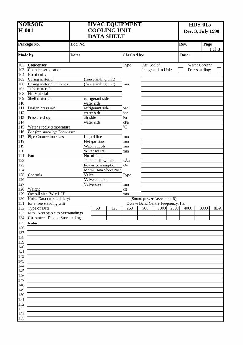
102 Condenser Type Air Cooled: Water Cooled:103 Conndenser location Integrated in Unit: Free standing:104 No of coils105 Casing material (free standing unit)106 Casing material thickness (free standing unit) mm107 Tube material108 Fin Material109 Shell material: refrigerant side110 water side111 Design pressure: refrigerant side bar112 water side bar113 Pressure drop air side Pa114 water side kPa115 Water supply temperature °C116 For free standing Condenser:117 Pipe Connection sizes Liquid line mm118 Hot gas line mm119 Water supply mm120 Water return mm121 Fan No. of fans122 Total air flow rate m3/s123 Power consumption kW124 Motor Data Sheet No.:125 Controls Valve Type126 Valve actuator127 Valve size mm128 Weight kg129 Overall size (W x L H) mm130 Noise Data (at rated duty) (Sound power Levels in dB)131 for a free standing unit Octave Band Centre Frequency, Hz132 Type of Data 63 125 250 500 1000 2000 4000 8000 dBA133 Max. Acceptable to Surroundings134 Guaranteed Data to Surroundings135 Notes:136137138139140141142143144145146147148149150151152153154155
HDS-015Rev. 3, July 1998

NORSOK HVAC EQUIPMENTH-001 DEHUMIDIFIER, SORPTION TYPE
DATA SHEETPackage No. Doc. No. Rev. Page
1 of 2Made by. Date: Checked by: Date:
Tag No. Location/ModuleUnit No. req'dHVAC System No. Inquiry No.Size & Type Quote No.Supplier P.O. No.Manufacturer Job No.Model Serial No.
1 Unit Composition2 Unit Description:34 Component Description Tag No. Reference5 Filter, process air6 Filter, regeneration air7 Rotor Unit8 Fan, process/dry air9 Motor for process/dry air fan Data sheet No.
10 Fan, regeneration/wet air11 Motor for regeneration/wet air fan12 Regeneration air heater Data sheet No.1314 Technical Data for complete Unit15 Main Data16 Function Range From 0 % RH to 100 % RH and17 from - 40°C to + 40°C18 Dehumidification capacity (at inlet condition 20°C/60%RH) kg/h19 Process/dry air flow m3/s20 Available static pressure process/dry air fan (excl. unit) Pa21 Regeneration/wet air flow m3/s22 Available static pressure regeneration/wet air fan (excl. unit) Pa23 Main Voltage v/Hz/Ph24 Control Voltage v/Hz/Ph25 Overall size (W x L x H) mm26 Service Space required mm27 Weight kg2829 Materials30 Unit frame material31 Casing Material32 Casing insulation material/thickness mm33 Base frame material34 Rotor material3536 Noise Data (at rated duty) (Sound power Levels in dB)37 Octave Band Centre Frequency, Hz38 63 125 250 500 1000 2000 4000 8000 dBA39 Max. Acceptable to Surroundings40 Max. Acceptable to Ducts41 Guaranteed Data to Surroundings42 Guaranteed Data to Ducts43 Notes:444546
HDS-016Rev 3, July 1998

NORSOK HVAC EQUIPMENTH-001 DEHUMIDIFIER, SORPTION TYPE
DATA SHEETPackage No. Doc. No. Rev. Page
2 of 2Made by. Date: Checked by: Date:
47 Component Technical Description48 Filter, Process Air Type49 Filter Class (Eurovent)50 No. of Filters51 Filter size (W x H) mm5253 Filter, Regeneration Air Type54 Filter Class (Eurovent)55 No. of Filters56 Filter size (W x H) mm5758 Rotor Unit Type/Size59 Rotor Motor Type/Manufacturer60 Power Supply v/Hz/Ph61 Rotor Belt Type/Manufacturer62 Desiccant material in rotor63 Washable rotor Yes: No:64 Washing detergent Type6566 Fan, process/dry air Type/Size67 Air Flow m3/s68 Drive Direct drive: Belt drive:69 Fan Power Consumption kW70 Fan Motor Speed rpm71 Fan Impeller Speed rpm72 Max. allowable Impeller Speed rpm73 Anti Spark Trak Yes: No:7475 Fan, regeneration/wet air Type/Size76 Air Flow m3/s77 Drive Direct drive: Belt drive:78 Fan Power Consumption kW79 Fan Motor Speed rpm80 Fan Impeller Speed rpm81 Max. allowable Impeller Speed rpm82 Anti Spark Trak Yes: No:8384 Regeneration air heater Manufacturer85 Type Electric: Water Coil:86 Heating Capacity kW87 Power Supply v/Hz/Ph88 Overheating thermostat (TSH/auto reset) Type89 Setpoint °C90 Safety thermostat (TSHH/manual reset) Type91 Setpoint °C92 Water inlet temperature °C93 Water outlet temperature °C94 Water Flow l/s95 Pressure drop (water side) kPa96 Casing material/thickness mm97 Tube material98 Notes:99
HDS-016Rev 3, July 1998

NORSOK HVAC EQUIPMENTH-001 LOUVRES
DATA SHEETPackage No. Doc. No. Rev. Page
1 of 1Made by. Date: Checked by: Date:
Tag No. Location/ModuleUnit No. req'dHVAC System No. Inquiry No.Size & Type Quote No.Supplier P.O. No.Manufacturer Job No.Model Serial No.
1 Technical Data 23 Airflow m³/s4 Separation Efficiency5 Face Velocity m/s6 Pressure Drop Pa7 Louvre Size/duct connection size Width mm8 Height mm9 Unit length mm
10 Drain Outlet (Note 1) Left: Right:11 Drain Outlet size mm12 Meshscreen Yes: No:13 Lifting Lugs Yes: No:14 Unit Weight kg151617 Materials18 Casing Material19 Thickness mm20 Blades Material21 Thickness mm22 Flange Norsok H-001, Annex A23 Meshscreen Material24 Mesh Size mm25 Drain Material26 Size mm27282930 Notes:31 1 Seen in the direction of the air flow323334353637383940414243444546
HDS-017Rev 3, July 1998

NORSOK HVAC EQUIPMENTH-001 DX COOLING COILS
DATA SHEETPackage No. Doc. No. Rev. Page
1 of 2Made by. Date: Checked by: Date:
Tag No. Location/ModuleUnit No. req'dHVAC System No. Inquiry No.Size & Type Quote No.Supplier P.O. No.Manufacturer Job No.Model Serial No.
1 Technical Data2 General3 Total Cooling Capacity (Design) kW4 Refrigerant Type5 Airside6 Air Flow m3/s7 Air Inlet Conditions °C/%RH8 Air Outlet Conditions °C/%RH9 Extreme Conditions: (Maximum Air Inlet conditions) °C/%RH
10 Air Pressure Drop Pa11 Coil Face Velocity m/s12 Refrigerant Side13 Evaporating Temperature °C14 Evaporating Pressure kPa15 Refrigerant Coil Leaving Temp °C16 Working Pressure kPa17 Design Pressure kPa18 Test Pressure (Nitrogen) kPa19 Thermostatic Expansion Valve (TEV)20 Number of TEV´s21 TEV Manufacturer/Type22 TEV's Superheat setting´s23 TEV's Spring Range´s kPa24 Number of Solenoid Valves kPa25 Solenoid Valve Manufacturer/Type26 Capacity control27 No of Cooling Stages28 Minimum Cooling Load - % Total Load %29 Hot Gas Injection Required Yes: No:30 Hot Gas Header Required Yes: No:31 Construction32 Coil Size (Face Area W x H) x L mm33 Coil Location Ductwork: Air Handling Unit:34 Coil Position Horisontal: Vertical:35 Tube Bundles Removeable Yes: No:36 Isolation Valves Fitted Yes: No:37 Drip Tray Required Yes: No:38 Droplet Eliminator Required Yes: No:39 Manometric Trap Required Yes: No:40 Trap Refill Point Required Yes: No:41 Manometric Trap Seal Depth mm42 Connection Position (Seen in direction of Air Flow) Left Side: Right Side:43 Minimum Fin Distance (Centre to centre) mm 2,544 Flange Standard (Duct connection) Norsok H-001, Annex A45 Weight - Dry kg46 Weight - Wet (operating) kg
HDS-018Rev. 3, July 1998
NORSOK HVAC EQUIPMENTH-001 DX COOLING COILS
DATA SHEETPackage No. Doc. No. Rev. Page
2 of 2Made by. Date: Checked by: Date:
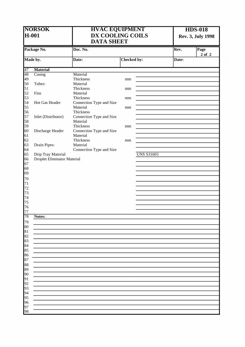
47 Material48 Casing Material49 Thickness mm50 Tubes: Material51 Thickness mm52 Fins Material53 Thickness mm54 Hot Gas Header Connection Type and Size55 Material mm56 Thickness57 Inlet (Distributor) Connection Type and Size58 Material59 Thickness mm60 Discharge Header Connection Type and Size61 Material62 Thickness mm63 Drain Pipes: Material64 Connection Type and Size65 Drip Tray Material UNS S3160366 Droplet Eliminator Material676869707172737475767778 Notes:7980818283848586878889909192939495969798
HDS-018Rev. 3, July 1998