hvac fund
TRANSCRIPT


Elsevier UK Prelims-P373998 3-11-2006 7:56a.m. Page:i Trimsize:6.5×9.5inches
Basal Font:Palatino Margins:Top:40pt Gutter:55pt Font Size:10/11 Text Width:29pc Depth:51 Lines
Fundamentals of HVAC Systems
SI Edition

This page intentionally left blank

Elsevier UK Prelims-P373998 3-11-2006 7:56a.m. Page:iii Trimsize:6.5×9.5inches
Basal Font:Palatino Margins:Top:40pt Gutter:55pt Font Size:10/11 Text Width:29pc Depth:51 Lines
Fundamentals of HVAC Systems
SI Edition
Prepared by
Robert McDowall, P. Eng.Engineering Change Inc.
American Society of Heating, Refrigerating andAir-Conditioning Engineers Inc.
1791 Tullie Circle NE, Atlanta, GA 30329, USA
Amsterdam • Boston • Heidelberg • London • New York • OxfordParis • San Diego • San Francisco • Singapore • Sydney • Tokyo
Elsevier UK Prelims-P373998 3-11-2006 7:56a.m. Page:iv Trimsize:6.5×9.5inches
Basal Font:Palatino Margins:Top:40pt Gutter:55pt Font Size:10/11 Text Width:29pc Depth:51 Lines
ElsevierThe Boulevard, Langford Lane, Kidlington, Oxford OX5 1GB, UK30 Corporate Drive, Suite 400, Burlington, MA 01803, USA
First edition 2007
Copyright © 2007, American Society of Heating, Refrigerating and Air-ConditioningEngineers, Inc. and Elsevier Inc. Published by Elsevier 2007. All rights reserved
The right American Society of Heating, Refrigerating and Air-ConditioningEngineers, Inc. and Elsevier Inc. to be identified as the author of this work has beenasserted in accordance with the Copyright, Designs and Patents Act 1988
No part of this publication may be reproduced, stored in a retrieval systemor transmitted in any form or by any means electronic, mechanical, photocopying,recording or otherwise without the prior written permission of the publisher
Permissions may be sought directly from Elsevier’s Science & Technology RightsDepartment in Oxford, UK: phone (+44) (0) 1865 843830; fax (+44) (0) 1865 853333;email: [email protected]. Alternatively you can submit your request online byvisiting the Elsevier web site at http://elsevier.com/locate/permissions, and selectingObtaining Permission to use Elsevier material
NoticeNo responsibility is assumed by the publisher for any injury and/or damage to personsor property as a matter of products liability, negligence or otherwise, or from any useor operation of any methods, products, instructions or ideas contained in the materialherein. Because of rapid advances in the medical sciences, in particular, independentverification of diagnoses and drug dosages should be made
British Library Cataloguing in Publication DataA catalogue record for this book is available from the British Library
Library of Congress Cataloging-in-Publication DataA catalog record for this book is available from the Library of Congress
ISBN–13: 978-0-12-373998-8ISBN–10: 0-12-373998-5
For information on all Elsevier publicationsvisit our web site at http://books.elsevier.com
Printed and bound in Great Briatin
06 07 08 09 10 10 9 8 7 6 5 4 3 2 1
Working together to grow libraries in developing countries
www.elsevier.com | www.bookaid.org | www.sabre.org

Elsevier UK Prelims-P373998 3-11-2006 7:56a.m. Page:v Trimsize:6.5×9.5inches
Basal Font:Palatino Margins:Top:40pt Gutter:55pt Font Size:10/11 Text Width:29pc Depth:51 Lines
Contents
Foreword ix
1 Introduction to HVAC 1
Instructions 1Study Objectives of Chapter 1 11.1 Introduction 11.2 Brief History of HVAC 21.3 Scope of Modern HVAC 31.4 Introduction to Air-Conditioning Processes 31.5 Objective: What is your system to achieve? 41.6 Environment For Human Comfort 6The Next Step 8Summary 9Bibliography 9
2 Introduction to HVAC Systems 11
Instructions 11Study Objectives of Chapter 2 112.1 Introduction 122.2 Introducing the Psychrometric Chart 122.3 Basic Air-Conditioning System 202.4 Zoned Air-Conditioning Systems 242.5 Choosing an Air-Conditioning System 272.6 System Choice Matrix 30The Next Step 31Summary 31Bibliography 33
3 Thermal Comfort 34
Instructions 34Study Objectives of Chapter 3 343.1 Introduction: What is Thermal Comfort? 343.2 Seven Factors Influencing Thermal Comfort 353.3 Conditions for Comfort 383.4 Managing Under Less Than Ideal Conditions 413.5 Requirements of Non-Standard Groups 42The Next Step 43Summary 43Bibliography 44
Elsevier UK Prelims-P373998 3-11-2006 7:56a.m. Page:vi Trimsize:6.5×9.5inches
Basal Font:Palatino Margins:Top:40pt Gutter:55pt Font Size:10/11 Text Width:29pc Depth:51 Lines
vi Contents
4 Ventilation and Indoor Air Quality 45
Instructions 45Study Objectives of Chapter 4 454.1 Introduction 454.2 Air Pollutants and Contaminants 464.3 Indoor Air Quality Effects on Health and Comfort 474.4 Controlling Indoor Air Quality 494.5 ASHRAE Standard 62, Ventilation for Acceptable Indoor Air
Quality 54The Next Step 59Summary 59Bibliography 60
5 Zones 62
Instructions 62Study Objectives of Chapter 5 625.1 Introduction 625.2 What is a Zone? 635.3 Zoning Design 635.4 Controlling the Zone 68The Next Step 69Summary 69
6 Single Zone Air Handlers and Unitary Equipment 71
Instructions 71Study Objectives of Chapter 6 716.1 Introduction 726.2 Examples of Buildings with Single-Zone Package
Air-Conditioning Units 726.3 Air-Handling Unit Components 736.4 The Refrigeration Cycle 786.5 System Performance Requirements 836.6 Rooftop Units 856.7 Split Systems 88The Next Step 89Summary 89Bibliography 91
7 Multiple Zone Air Systems 92
Instructions 92Study Objectives of Chapter 7 927.1 Introduction 937.2 Single-Duct, Zoned-Reheat, Constant-Volume Systems 947.3 Single-Duct, Variable-Air-Volume Systems (VAV) 967.4 Bypass Box Systems 987.5 Constant-Volume, Dual-Duct, All-Air Systems 997.6 Multizone Systems 1027.7 Three-Deck Multizone Systems 1037.8 Dual-Duct, Variable-Air-Volume Systems 1047.9 Dual-Path Outside-Air Systems 105

Elsevier UK Prelims-P373998 3-11-2006 7:56a.m. Page:vii Trimsize:6.5×9.5inches
Basal Font:Palatino Margins:Top:40pt Gutter:55pt Font Size:10/11 Text Width:29pc Depth:51 Lines
Contents vii
The Next Step 105Summary 106
8 Hydronic Systems 108
Instructions 108Study Objectives of Chapter 8 1088.1 Introduction 1098.2 Natural Convection and Low Temperature Radiation Heating
Systems 1108.3 Panel Heating and Cooling 1138.4 Fan Coils 1148.5 Two-Pipe Induction Systems 1178.6 Water Source Heat Pumps 118The Next Step 120Summary 120Bibliography 121
9 Hydronic System Architecture 122
Instructions 122Study Objectives of Chapter 9 1229.1 Introduction 1239.2 Steam Systems 1239.3 Water Systems 1259.4 Hot Water Systems 1299.5 Chilled Water Systems 1339.6 Condenser Water 134The Next Step 137Summary 137Bibliography 138
10 Central Plants 139
Instructions 139Study Objectives of Chapter 10 13910.1 Introduction 14010.2 Central Plant Versus Local Plant in a Building 14010.3 Boilers 14210.4 Chillers 14510.5 Cooling Towers 148The Next Step 151Summary 152Bibliography 153
11 Controls 154
Instructions 154Study Objectives of Chapter 11 15411.1 Introduction 15511.2 Controls Basics 15611.3 Typical Control loops 16111.4 Introduction to Direct Digital Control (DDC) 16311.5 Direct Digital Control of an Air-Handler 168

Elsevier UK Prelims-P373998 3-11-2006 7:56a.m. Page:viii Trimsize:6.5×9.5inches
Basal Font:Palatino Margins:Top:40pt Gutter:55pt Font Size:10/11 Text Width:29pc Depth:51 Lines
viii Contents
11.6 Architecture and Advantages of Direct Digital Controls 172The Next Step 175Summary 176Bibliography 177
12 Energy Conservation Measures 178
Instructions 178Study Objectives of Chapter 12 17812.1 Introduction 17912.2 Energy Considerations For Buildings 17912.3 ASHRAE/IESNA Standard 90.1-2004 18312.4 Heat Recovery 18612.5 Air-Side and Water-Side Economizers 19012.6 Evaporative Cooling 19212.7 Control of Building Pressure 194The Final Step 194Summary 195Bibliography 196
13 Special Applications 197
Instructions 197Study Objectives of Chapter 13 19713.1 Introduction 19813.2 Radiant Heating and Cooling Systems 19813.3 Thermal Storage Systems 20113.4 The Ground as Heat Source and Sink 21113.5 Occupant-Controlled Windows with HVAC 21213.6 Room Air Distribution Systems 21313.7 Decoupled and Dedicated Outdoor Air Systems 217Summary 220Your Next Step 222Bibliography 223Epilogue 223
Index 225
Elsevier UK Prelims-P373998 3-11-2006 7:56a.m. Page:ix Trimsize:6.5×9.5inches
Basal Font:Palatino Margins:Top:40pt Gutter:55pt Font Size:10/11 Text Width:29pc Depth:51 Lines
Foreword
Every author knows that books are not created in a vacuum, so it is importantto acknowledge the support of those who also contributed to the success ofthe project.
First I would like to thank my wife Jo-Anne McDowall, who helped withthe development of the project, and who read every word, to make sure thata neophyte to the field of HVAC would understand the concepts as theywere introduced. Jo-Anne also wrote the chapter summaries and leant herproofreading and text-editing eye to this task.
I would like to thank the members of ASHRAE Winnipeg, and especiallyBert Phillips, P. Eng., who encouraged and supported me in the developmentof the project.
Of course, the project would never have come to fruition without ASHRAEmembers who acted as reviewers.
Finally thanks to ASHRAE and Elsevier staff who made it happen.

This page intentionally left blank

Elsevier UK Ch01-P373998 3-11-2006 7:18a.m. Page:1 Trimsize:6.5×9.5inches
Basal Font:Palatino Margins:Top:40pt Gutter:55pt Font Size:10/11 Text Width:29pc Depth:51 Lines
Chapter 1
Introduction to HVAC
Contents of Chapter 1
InstructionsObjectives of Chapter 11.1 Introduction1.2 Brief History of HVAC1.3 Scope of Modern HVAC1.4 Introduction to Air-Conditioning Processes1.5 Objective: What is your system to achieve?1.6 Environment For Human ComfortThe Next StepSummaryBibliography
Instructions
Read the material of Chapter 1. Re-read the parts of the chapter that areemphasized in the summary and memorize important definitions.
Objectives of Chapter 1
Chapter 1 introduces the history, uses and main processes of heating, venti-lating and air conditioning. There are no calculations to be done. The ideaswill be addressed in detail in later chapters. After studying the chapter, youshould be able to:
Define heating, ventilating, and air conditioning.Describe the purposes of heating, ventilating, and air conditioning.Name and describe seven major air-conditioning processes.Identify five main aspects of a space that influence an occupant’s comfort.
1.1 Introduction
Heating, Ventilating, and Air Conditioning (HVAC) is a huge field. HVACsystems include a range from the simplest hand-stoked stove, used for comfort

Elsevier UK Ch01-P373998 3-11-2006 7:18a.m. Page:2 Trimsize:6.5×9.5inches
Basal Font:Palatino Margins:Top:40pt Gutter:55pt Font Size:10/11 Text Width:29pc Depth:51 Lines
2 Fundamentals of HVAC
heating, to the extremely reliable total air-conditioning systems found in sub-marines and space shuttles. Cooling equipment varies from the small domesticunit to refrigeration machines that are 10,000 times the size, which are used inindustrial processes.
Depending on the complexity of the requirements, the HVAC designer mustconsider many more issues than simply keeping temperatures comfortable.This chapter will introduce you to the fundamental concepts that are used bydesigners to make decisions about system design, operation, and maintenance.
1.2 Brief History of HVAC
For millennia, people have used fire for heating. Initially, the air required tokeep the fire going ensured adequate ventilation for the occupants. However,as central furnaces with piped steam or hot water became available for heating,the need for separate ventilation became apparent. By the late 1880s, rules ofthumb for ventilation design were developed and used in many countries.
In 1851 Dr. John Gorrie was granted U.S. patent 8080 for a refrigerationmachine. By the 1880s, refrigeration became available for industrial purposes.Initially, the two main uses were freezing meat for transport and making ice.However, in the early 1900s there was a new initiative to keep buildings coolfor comfort. Cooling the New York Stock Exchange, in 1902, was one of thefirst comfort cooling systems. Comfort cooling was called “air conditioning.”
Our title, “HVAC,” thus captures the development of our industry. The term“air conditioning” has gradually changed, from meaning just cooling to thetotal control of:
• Temperature• Moisture in the air (humidity)• Supply of outside air for ventilation• Filtration of airborne particles• Air movement in the occupied space.
Throughout the rest of this text we will use the term “air conditioning” toinclude all of these issues and continue to use “HVAC” where only some ofthe elements of full air conditioning are being controlled.
To study the historical record of HVAC is to take a fascinating trip throughthe tremendous technical and scientific record of society. There are the pioneerssuch as Robert Boyle, Sadi Carnot, John Dalton, James Watt, Benjamin Franklin,John Gorrie, Lord Kelvin, Ferdinand Carré, Willis Carrier, and Thomas Midg-ley, along with many others, who have brought us to our current state. Air-conditioning technology has developed since 1900 through the joint accom-plishments of science and engineering. Advances in thermodynamics, fluidmechanics, electricity, electronics, construction, materials, medicine, controls,and social behavior are the building blocks to better engineered products ofair conditioning.
Historical accounts are not required as part of this course but, for the enjoy-ment and perspective it provides, it is worth reading an article such as Mile-stones in Air Conditioning, by Walter A. Grant1 or the book about Willis Carrier,The Father of Air Conditioning.2 The textbook Principles of Heating, Ventilating,and Air Conditioning,3 starts with a concise and comprehensive history of theHVAC industry.

Elsevier UK Ch01-P373998 3-11-2006 7:18a.m. Page:3 Trimsize:6.5×9.5inches
Basal Font:Palatino Margins:Top:40pt Gutter:55pt Font Size:10/11 Text Width:29pc Depth:51 Lines
Introduction to HVAC 3
HVAC evolved based on:
• Technological discoveries, such as refrigeration, that were quickly adoptedfor food storage.
• Economic pressures, such as the reduction in ventilation rates after the 1973energy crisis.
• Computerization and networking, used for sophisticated control of largecomplex systems serving numerous buildings.
• Medical discoveries, such as the effects of second hand smoke on people,which influenced ventilation methods.
1.3 Scope of Modern HVAC
Modern air conditioning is critical to almost every facet of advancing humanactivity. Although there have been great advances in HVAC, there are severalareas where active research and debate continue.
Indoor air quality is one that directly affects us. In many countries of the worldthere is a rapid rise in asthmatics and increasing dissatisfaction with indoor airquality in buildings and planes. The causes and effects are extremely complex.A significant scientific and engineering field has developed to investigate andaddress these issues.
Greenhouse gas emissions and the destruction of the earth’s protective ozonelayer are concerns that are stimulating research. New legislation and guidelinesare evolving that encourage: recycling; the use of new forms of energy; lessenergy usage; and low polluting materials, particularly refrigerants. All theseissues have a significant impact on building design, including HVAC systemsand the design codes.
Energy conservation is an ongoing challenge to find novel ways to reduceconsumption in new and existing buildings without compromising comfortand indoor air quality. Energy conservation requires significant cooperationbetween disciplines.
For example, electric lighting produces heat. When a system is in a coolingmode, this heat is an additional cooling load. Conversely, when the system is ina heating mode, the lighting heat reduces the load on the building heating sys-tem. This interaction between lighting and HVAC is the reason that ASHRAEand the Illuminating Engineering Society of North America (IESNA) joinedforces to write the building energy conservation standard, ASHRAE Standard90.1-2004, Energy Standard for Buildings Except Low-Rise Residential Buildings.4
1.4 Introduction to Air-Conditioning Processes
As mentioned earlier, the term “air conditioning,” when properly used, nowmeans the total control of temperature, moisture in the air (humidity), supplyof outside air for ventilation, filtration of airborne particles, and air movementin the occupied space. There are seven main processes required to achieve fullair conditioning and they are listed and explained below:
The processes are:
1. Heating—the process of adding thermal energy (heat) to the conditionedspace for the purposes of raising or maintaining the temperature of the space.
Elsevier UK Ch01-P373998 3-11-2006 7:18a.m. Page:4 Trimsize:6.5×9.5inches
Basal Font:Palatino Margins:Top:40pt Gutter:55pt Font Size:10/11 Text Width:29pc Depth:51 Lines
4 Fundamentals of HVAC
2. Cooling—the process of removing thermal energy (heat) from the condi-tioned space for the purposes of lowering or maintaining the temperatureof the space.
3. Humidifying—the process of adding water vapor (moisture) to the air in theconditioned space for the purposes of raising or maintaining the moisturecontent of the air.
4. Dehumidifying—the process of removing water vapor (moisture) from theair in the conditioned space for the purposes of lowering or maintaining themoisture content of the air.
5. Cleaning—the process of removing particulates (dust, etc.) and biologicalcontaminants (insects, pollen, etc.) from the air delivered to the conditionedspace for the purposes of improving or maintaining the air quality.
6. Ventilating—the process of exchanging air between the outdoors and theconditioned space for the purposes of diluting the gaseous contaminants inthe air and improving or maintaining air quality, composition, and fresh-ness. Ventilation can be achieved either through natural ventilation or mechan-ical ventilation. Natural ventilation is driven by natural draft, like when youopen a window. Mechanical ventilation can be achieved by using fans todraw air in from outside or by fans that exhaust air from the space tooutside.
7. Air Movement—the process of circulating and mixing air through condi-tioned spaces in the building for the purposes of achieving the properventilation and facilitating the thermal energy transfer.
The requirements and importance of the seven processes varies. In a climatethat stays warm all year, heating may not be required at all. Conversely, ina cold climate the periods of heat in the summer may be so infrequent as tomake cooling unnecessary. In a dry desert climate, dehumidification may beredundant, and in a hot, humid climate dehumidification may be the mostimportant design aspect of the air-conditioning system.
Defining Air conditioning
The actual use of the words “air conditioning” varies considerably, so it isalways advisable to check what is really meant. Consider, for example, “win-dow air conditioners.” The vast majority provide cooling, some dehumidifica-tion, some filtering, and some ventilation when the outside temperature is wellabove freezing. They have no ability to heat or to humidify the conditionedspace and do not cool if it is cold outside.
In colder climates, heating is often provided by a separate, perimeter heatingsystem that is located within the outside walls. The other functions: cooling,humidification, dehumidification, cleaning, ventilating, and air movement areall provided by a separate air system, often referred to as the “air-conditioningsystem.” It is important to remember that both the heating and the air systemtogether form the “air-conditioning” system for the space.
1.5 Objective: What is your system to achieve?
Before starting to design a system, it is critical that you know what your systemis to achieve.

Elsevier UK Ch01-P373998 3-11-2006 7:18a.m. Page:5 Trimsize:6.5×9.5inches
Basal Font:Palatino Margins:Top:40pt Gutter:55pt Font Size:10/11 Text Width:29pc Depth:51 Lines
Introduction to HVAC 5
Often, the objective is to provide a comfortable environment for the humanoccupants, but there are many other possible objectives: creating a suitableenvironment for farm animals; regulating a hospital operating room; maintain-ing cold temperatures for frozen food storage; or maintaining temperature andhumidity to preserve wood and fiber works of art. Whatever the situation, itis important that the objective criteria for system success are clearly identifiedat the start of the project, because different requirements need different designconsiderations.
Let us very briefly consider some specific design situations and the types ofperformance requirements for HVAC systems.
Example 1: Farm animals. The design issues are economics, the health andwell-being of both animals and workers, plus any regulations. Farm animalspaces are always ventilated. Depending on the climate, cooling and/orheating may be provided, controlled by a simple thermostat. The ventilationrate may be varied to:
• Maintain indoor air quality (removal of body and excrement fumes).• Maintain inside design temperature (bring in cool air and exhaust hot air).• Remove moisture (bring in drier air and exhaust moist air).• Change the air movement over the animals (higher air speed provides
cooling).
A complex control of ventilation to meet the four design requirementsmay well be very cost effective. However, humidification and cleaning arenot required.
Example 2: Hospital operating room. This is a critical environment, often servedby a dedicated air-conditioning system. The design objectives include:
• Heating, to avoid the patient from becoming too cold.• Cooling, to prevent the members of the operating team from becoming
too hot.• Control adjustment by the operating team for temperatures between 18 �C
(Centigrade) and 27 �C.• Humidifying, to avoid low humidity and the possibility of static electricity
sparks.• Dehumidifying, to minimize any possibility of mold and to minimize
operating team discomfort.• Cleaning the incoming air with very high efficiency filters, to remove any
airborne organisms that could infect the patient.• Ventilating, to remove airborne contaminants and to keep the theatre fresh.• Providing steady air movement from ceiling supply air outlets down over
the patient for exhaust near the floor, to minimize contamination of theoperating site.
This situation requires a very comprehensive air-conditioning system.
Example 3: Frozen food storage. The ideal temperature for long storage varies:i.e., ice cream requires temperatures below −25 �C and meat requires temper-atures below −20 �C. The design challenge is to ensure that the temperatureis accurately maintained and that the temperature is as even as possible

Elsevier UK Ch01-P373998 3-11-2006 7:18a.m. Page:6 Trimsize:6.5×9.5inches
Basal Font:Palatino Margins:Top:40pt Gutter:55pt Font Size:10/11 Text Width:29pc Depth:51 Lines
6 Fundamentals of HVAC
throughout the storage facility. Here, accurate cooling and good air move-ment are the prime issues. Although cooling and air movement are required,we refer to this system as a “freezer,” not as an air-conditioning system,because heating, ventilation, humidification, and dehumidification are notcontrolled.
Example 4: Preserving wood and fiber works of art. The objectives in this envi-ronment are to minimize any possibility of mold, by keeping the humiditylow, and to minimize drying out, by keeping the humidity up. In addition,it is important to minimize the expansion and contraction of specimens thatcan occur as the moisture content changes. As a result the design challengeis to maintain a very steady humidity, reasonably steady temperature, andto minimize required ventilation, from a system that runs continuously.For this situation, the humidity control is the primary issue and tempera-ture control is secondary. Typically, this situation will require all seven ofthe air-conditioning features and we will describe the space as fully “air-conditioned.”
Now let us go on to consider the more complex subject of human comfortin a space.
1.6 Environment For Human Comfort
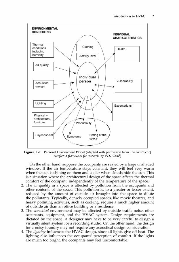
“Provide a comfortable environment for the occupants” sounds like a simpleobjective, until you start to consider the variety of factors that influence thecomfort of an individual. Figure 1-1 is a simplified diagram of the three maingroups of factors that affect comfort.
• Attributes of the space – on the left• Characteristics of the individual – on the right• Clothing and activity of the individual – high center
1.6.1 Attributes of the Space Influencing Comfort
As you can see, six attributes of the space influence comfort: thermal, air qual-ity, acoustical, lighting, physical, and psychosocial. Of these, only the thermalconditions and air quality can be directly controlled by the HVAC system. Theacoustical (noise) environment may be influenced to some extent. The light-ing and architectural aspects are another field, but these can influence howthe HVAC is perceived. The psychosocial environment (how people interactsociably or unsociably!) in the space is largely dependent on the occupants,rather than the design of the space.
We will briefly consider these six aspects of the space and their influence oncomfort.
1. Thermal conditions include more than simply the air temperature. If the airspeed is very high, the space will be considered drafty. If there is no airmovement, occupants may consider the space “stuffy.” The air velocity ina mechanically conditioned space is largely controlled by the design of thesystem.
Elsevier UK Ch01-P373998 3-11-2006 7:18a.m. Page:7 Trimsize:6.5×9.5inches
Basal Font:Palatino Margins:Top:40pt Gutter:55pt Font Size:10/11 Text Width:29pc Depth:51 Lines
Introduction to HVAC 7
Thermal conditionsincludinghumidity
Air quality
Acoustical(noise)
Lighting
Physical – architectural,furniture
Health
Vulnerability
Expectations
ENVIRONMENTAL CONDITIONS
INDIVIDUALCHARACTERISTICS
Productivity
Rating of the space
Symptoms
Clothing
Activity level
Psychosocial
Individualperson
Figure 1-1 Personal Environment Model (adapted with permission from The construct ofcomfort: a framework for research, by W.S. Cain5)
On the other hand, suppose the occupants are seated by a large unshadedwindow. If the air temperature stays constant, they will feel very warmwhen the sun is shining on them and cooler when clouds hide the sun. Thisis a situation where the architectural design of the space affects the thermalcomfort of the occupant, independently of the temperature of the space.
2. The air quality in a space is affected by pollution from the occupants andother contents of the space. This pollution is, to a greater or lesser extent,reduced by the amount of outside air brought into the space to dilutethe pollutants. Typically, densely occupied spaces, like movie theatres, andheavy polluting activities, such as cooking, require a much higher amountof outside air than an office building or a residence.
3. The acoustical environment may be affected by outside traffic noise, otheroccupants, equipment, and the HVAC system. Design requirements aredictated by the space. A designer may have to be very careful to design avirtually silent system for a recording studio. On the other hand, the designfor a noisy foundry may not require any acoustical design consideration.
4. The lighting influences the HVAC design, since all lights give off heat. Thelighting also influences the occupants’ perception of comfort. If the lightsare much too bright, the occupants may feel uncomfortable.
Elsevier UK Ch01-P373998 3-11-2006 7:18a.m. Page:8 Trimsize:6.5×9.5inches
Basal Font:Palatino Margins:Top:40pt Gutter:55pt Font Size:10/11 Text Width:29pc Depth:51 Lines
8 Fundamentals of HVAC
5. The physical aspects of the space that have an influence on the occupantsinclude both the architectural design aspects of the space and the inte-rior design. Issues like chair comfort, the height of computer keyboards,or reflections off computer screens have no relation to the HVAC design,however they may affect how occupants perceive the overall comfort ofthe space.
6. The psychosocial situation, the interaction between people in the space, is nota design issue but can create strong feelings about the comfort of the space.
1.6.2 Characteristics of the Individual that Influence Comfort
Now let us consider the characteristics of the occupants of the space. All peoplebring with them health, vulnerabilities, and expectations.
Their health may be excellent and they may not even notice the draft fromthe air conditioning. On the other hand, if the occupants are patients in adoctor’s waiting room, they could perceive a cold draft as very uncomfortableand distressing.
The occupants can also vary in vulnerability. For example, cool floors willlikely not affect an active adult who is wearing shoes. The same floor may beuncomfortably cold for the baby who is crawling around on it.
Lastly the occupants bring their expectations. When we enter a prestigioushotel, we expect it to be comfortable. When we enter an air-conditioned build-ing in summer, we expect it to be cool. The expectations may be based onprevious experience in the space or based on the visual perception of thespace. For example, when you enter the changing room in the gym, youexpect it to be smelly, and your expectations make you more tolerant of thereality.
1.6.3 Clothing and Activity as a function of Individual Comfort
The third group of factors influencing comfort is the amount of clothing andthe activity level of the individual. If we are wearing light clothing, the spaceneeds to be warmer for comfort than if we are heavily clothed. Similarly, whenwe are involved in strenuous activity, we generate considerable body heat andare comfortable with a lower space temperature.
In the summer, in many business offices, managers wear suits with shirtsand jackets while staff members may have bare arms, and light clothing. Thesame space may be thermally comfortable to one group and uncomfortable tothe other.
There is much more to comfort than most people realize. These variousaspects of comfort will be covered in more detail in later chapters.
The Next Step
Chapter 2 introduces the concept of an air-conditioning system. We will thenconsider characteristics of systems and how various parameters influence sys-tem choice.

Elsevier UK Ch01-P373998 3-11-2006 7:18a.m. Page:9 Trimsize:6.5×9.5inches
Basal Font:Palatino Margins:Top:40pt Gutter:55pt Font Size:10/11 Text Width:29pc Depth:51 Lines
Introduction to HVAC 9
Summary
This has been an introduction to heating, ventilating, and air conditioningand some of the terminology and main processes that are involved in airconditioning.
1.2 Brief History of HVAC
The field of HVAC started in the mid-1800s. The term “air conditioning” hasgradually changed from meaning just cooling to the total control of temper-ature, moisture in the air (humidity), supply of outside air for ventilation,filtration of airborne particles, and air movement in the occupied space.
1.3 Scope of Modern HVAC
Some of the areas of research, regulation, and responsibility include indoor airquality, greenhouse gas emissions, and energy conservation.
1.4 Introduction to Air-Conditioning Processes
There are seven main processes required to achieve full air conditioning: heat-ing, cooling, humidifying, dehumidifying, cleaning, ventilating, air movement.The requirements and importance of the seven processes vary with the climate.
1.5 System Objectives
Before starting to design a system, it is critical that you know what your systemis supposed to achieve. The objective will determine the type of system toselect, and the performance goals for it.
1.6 Environment For Human Comfort
The requirements for human comfort are affected by: the physical space; thecharacteristics of the individual, including health, vulnerability, and expecta-tions; and the clothing and activities of the individual.
Six attributes of the physical space that influence comfort are thermal, airquality, acoustical, lighting, physical, and the psychosocial environment. Ofthese, only the thermal conditions and air quality can be directly controlledby the HVAC system. The acoustical (noise) environment may be influencedto some extent. The lighting and architectural aspects can influence how theHVAC is perceived. The psychosocial environment in the space is largelydependent on the occupants rather than the design of the space.
Bibliography
1. Grant, W. 1969. “Milestones in Air Conditioning.” ASHRAE Journal 11(9): 45–51.2. Ingels, M. 1991. The Father of Air Conditioning. Louisville, KY: Fetter Printing Co.
Elsevier UK Ch01-P373998 3-11-2006 7:18a.m. Page:10 Trimsize:6.5×9.5inches
Basal Font:Palatino Margins:Top:40pt Gutter:55pt Font Size:10/11 Text Width:29pc Depth:51 Lines
10 Fundamentals of HVAC
3. Sauer, Harry J., Jr., Ronald H. Howell, and William J. Coad. 2001. Principles of Heating,Ventilating, and Air Conditioning. Atlanta: American Society of Heating, Refrigeratingand Air-Conditioning Engineers, Inc.
4. ASHRAE. 2004. ASHRAE Standard 90.1-2004, Energy Standard for Buildings ExceptLow-Rise Residential Buildings. Atlanta: American Society of Heating, Refrigeratingand Air-Conditioning Engineers, Inc.
5. Cain, W.S. 2002. The construct of comfort: a framework for research. Proceedings:Indoor Air 2002, Volume II, pp. 12–20.

Elsevier UK Ch02-P373998 3-11-2006 7:22a.m. Page:11 Trimsize:6.5×9.5inches
Basal Font:Palatino Margins:Top:40pt Gutter:55pt Font Size:10/11 Text Width:29pc Depth:51 Lines
Chapter 2
Introduction to HVAC Systems
Contents of Chapter 2
InstructionsObjectives of Chapter 22.1 Introduction2.2 Introducing the Psychrometric Chart2.3 Basic Air-Conditioning System2.4 Zoned Air-Conditioning Systems2.5 Choosing an Air-Conditioning System2.6 System Choice MatrixThe Next StepSummaryBibliography
Instructions
Read the material of Chapter 2. Re-read the parts of the chapter that areemphasized in the summary.
Objectives of Chapter 2
Chapter 2 begins with an introduction to a graphical representation ofair-conditioning processes called the psychrometric chart. Next, an air-conditioning system is introduced followed by a discussion about how it canbe adapted to serve many spaces. The chapter ends with a brief introduc-tion to the idea of using a factor matrix to help choose an air-conditioningsystem.
Chapter 2 is broad in scope and will also introduce you to the content andvalue of other, more in depth, ASHRAE Self-Study Courses. After studyingChapter 2, you should be able to:
Understand and describe the major concepts of the psychrometric chart.Define the main issues to be considered when designing a system.Name the four major system types and explain their differences.Describe the main factors to be considered in a matrix selection process.

Elsevier UK Ch02-P373998 3-11-2006 7:22a.m. Page:12 Trimsize:6.5×9.5inches
Basal Font:Palatino Margins:Top:40pt Gutter:55pt Font Size:10/11 Text Width:29pc Depth:51 Lines
12 Fundamentals of HVAC
2.1 Introduction
In Chapter 1 we introduced the seven main air-conditioning processes and thetask of establishing objectives for air-conditioning design. In this chapter wewill consider:
How these processes are described graphically in the psychrometric chart.How these processes are combined to form an air-conditioning system.The range of heating, ventilating, and air-conditioning systems.How system choices are made.
2.2 Introducing the Psychrometric Chart
Many of the air-conditioning processes involve air that is experiencing energychanges. These changes arise from changes in the air’s temperature andits moisture content. The relationships between temperature, moisture con-tent, and energy are most easily understood using a visual aid called the“psychrometric chart.”
The psychrometric chart is an industry-standard tool that is used to visu-alize the interrelationships between dry air, moisture, and energy. If you areresponsible for the design or maintenance of any aspect of air conditioning inbuildings, a clear and comfortable understanding of the chart will make yourjob easier.
Initially, the chart can be intimidating, but as you work with it, you willdiscover that the relationships that it illustrates are relatively easy to under-stand. Once you are comfortable with it, you will discover that it is a toolthat can make it easier to troubleshoot air-conditioning problems in buildings.The ASHRAE course, Fundamentals of Thermodynamics and Psychrometrics,1 goesinto great detail about the use of the chart. That course also provides cal-culations and discussion about how the chart can be used as a design andtroubleshooting tool.
In this course, however, we will only introduce the psychrometric chart, andprovide a very brief overview of its structure.
The Design of the Psychrometric Chart
The psychrometric chart is built upon two simple concepts.
1. Indoor air is a mixture of dry air and water vapor.2. There is a specific amount of energy in the mixture at a specific temperature
and pressure.
Psychrometric Chart Concept 1: Indoor Air is a Mixture of Dry Air and Water Vapor.
The air we live in is a mixture of both dry air and water vapor. Both areinvisible gases. The water vapor in air is also called moisture or humidity.The quantity of water vapor in air is expressed as “grams of water vapor perkilogram of air.” This ratio is called the “humidity ratio,” abbreviation W andthe units are grams of water/kilogram of dry air, gw/kgda, often abbreviatedto g/kg.
The exact properties of moist air vary with pressure. Because pressurereduces as altitude increases, the properties of moist air change with altitude.

Elsevier UK Ch02-P373998 3-11-2006 7:22a.m. Page:13 Trimsize:6.5×9.5inches
Basal Font:Palatino Margins:Top:40pt Gutter:55pt Font Size:10/11 Text Width:29pc Depth:51 Lines
Introduction to HVAC Systems 13
Typically, psychrometric charts are printed based on standard pressure at sealevel. For the rest of this course we will consider pressure as constant.
To understand the relationship between water vapor, air, and temperature,we will consider two conditions:
First Condition: The temperature is constant, but the quantity of water vaporis increasing.
If the temperature remains constant, then, as the quantity of water vaporin the air increases, the humidity increases. However, at every temperaturepoint, there is a maximum amount of water vapor that can co-exist with theair. The point at which this maximum is reached is called the saturation point.If more water vapor is added after the saturation point is reached, then anequal amount of water vapor condenses, and takes the form of either waterdroplets or ice crystals.
Outdoors, we see water droplets in the air as fog, clouds, or rain and we seeice crystals in the air as snow or hail. The psychrometric chart only considers theconditions up to the saturation point; therefore, it only considers the effects ofwater in the vapor phase, and does not deal with water droplets or ice crystals.
Second Condition: The temperature is dropping, but the quantity of watervapor is constant.
If the air is cooled sufficiently, it reaches the saturation line. If it is cooledeven more, moisture will condense out and dew forms.
For example, if a cold canned drink is taken out of the refrigerator andleft for a few minutes, the container gets damp. This is because the moistair is in contact with the chilled container. The container cools the air thatit contacts to a temperature that is below saturation, and dew forms. Thistemperature, at which the air starts to produce condensation, is called the dewpoint temperature.
Relative Humidity
Figure 2-1 is a plot of the maximum quantity of water vapor per pound of airagainst air temperature. The X-axis is temperature. The Y-axis is the proportionof water vapor to dry air, measured in grams of water vapor per kilogram
Figure 2-1 Psychrometric Chart—Saturation Line

Elsevier UK Ch02-P373998 3-11-2006 7:22a.m. Page:14 Trimsize:6.5×9.5inches
Basal Font:Palatino Margins:Top:40pt Gutter:55pt Font Size:10/11 Text Width:29pc Depth:51 Lines
14 Fundamentals of HVAC
of dry air. The curved “maximum water vapor line” is called the “saturationline.” It is also known as 100% relative humidity, abbreviated to 100% rh.At any point on the saturation line, the air has 100% of the water vapor perpound of air that can coexist with dry air at that temperature.
When the same volume of air contains only half the weight of water vaporthat it has the capacity to hold at that temperature, we call it 50% relativehumidity or 50% rh. This is shown in Figure 2-2. Air at any point on the 50%rh line has half the water vapor that the same volume of air could have at thattemperature.
As you can see on the chart, the maximum amount of water vapor that moistair can contain increases rapidly with increasing temperature. For example,moist air at the freezing point, 0 �C, can contain only 0.4% of its weight aswater vapor. However, indoors, at a temperature of 22 �C the moist air cancontain nearly 1.7% of its weight as water vapor—over four times as much.
Consider Figure 2-3, and this example:On a miserable wet day it might be 5 �C outside, with the air rather humid,
at 80% relative humidity. Bring that air into your building. Heat it to 22 �C.This brings the relative humidity down to about 25%. This change in relativehumidity is shown in Figure 2-3, from Point 1 → 2. A cool damp day outsideprovides air for a dry day indoors! Note that the absolute amount of watervapor in the air has remained the same, at 4 grams of water vapor per kilogramof dry air; but as the temperature rises, the relative humidity falls.
Here is an example for you to try, using Figure 2-3.Suppose it is a warm day with an outside temperature of 30 �C and relative
humidity at 50%. We have an air-conditioned space that is at 22 �C. Someof the outside air leaks into our air-conditioned space. This leakage is calledinfiltration.
Plot the process on Figure 2-3.Find the start condition, 30 �C and 50% rh, moisture content 12 g/kg.Then cool this air: move left, at constant moisture content to 23 �C.Notice that the cooled air now has a relative humidity of about 75%.
Figure 2-2 Psychrometric Chart—50% Relative Humidity Line

Elsevier UK Ch02-P373998 3-11-2006 7:22a.m. Page:15 Trimsize:6.5×9.5inches
Basal Font:Palatino Margins:Top:40pt Gutter:55pt Font Size:10/11 Text Width:29pc Depth:51 Lines
Introduction to HVAC Systems 15
Figure 2-3 Psychrometric Chart—Change in Relative Humidity with Change in Temperature
Relative humidity of 75% is high enough to cause mold problems inbuildings. Therefore in hot moist climates, to prevent infiltration andmold generation, it is valuable to maintain a small positive pressure inbuildings.
Psychrometric Chart Concept 2: There is a specific amount of energy in the air mixtureat a specific temperature and pressure.
This brings us to the second concept that the psychrometric chart illustrates.There is a specific amount of energy in the air water-vapor mixture at a specifictemperature. The energy of this mixture is dependent on two measures:
1. The temperature of the air.2. The proportion of water vapor in the air.
There is more energy in air at higher temperatures. The addition of heatto raise the temperature is called adding “sensible heat.” There is also moreenergy when there is more water vapor in the air. The energy that the watervapor contains is referred to as its “latent heat.”
The measure of the total energy of both the sensible heat in the air and thelatent heat in the water vapor is commonly called “enthalpy.” Enthalpy canbe raised by adding energy to the mixture of dry air and water vapor. Thiscan be accomplished by adding either or both
• Sensible heat to the air• More water vapor, which increases the latent heat of the mixture.
On the psychrometric chart, lines of constant enthalpy slope down from leftto right as shown in Figure 2-4 and are labeled “Enthalpy.”
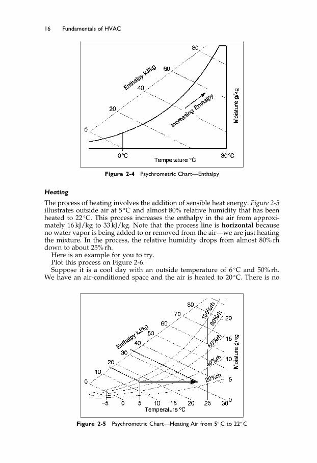
The zero is arbitrarily chosen as zero at 0 �C and zero moisture content. Theunit measure for enthalpy is kilojoules per kilogram of dry air, abbreviatedas kJ/kg.
Elsevier UK Ch02-P373998 3-11-2006 7:22a.m. Page:16 Trimsize:6.5×9.5inches
Basal Font:Palatino Margins:Top:40pt Gutter:55pt Font Size:10/11 Text Width:29pc Depth:51 Lines
16 Fundamentals of HVAC
Figure 2-4 Psychrometric Chart—Enthalpy
Heating
The process of heating involves the addition of sensible heat energy. Figure 2-5illustrates outside air at 5 �C and almost 80% relative humidity that has beenheated to 22 �C. This process increases the enthalpy in the air from approxi-mately 16 kJ/kg to 33 kJ/kg. Note that the process line is horizontal becauseno water vapor is being added to or removed from the air—we are just heatingthe mixture. In the process, the relative humidity drops from almost 80% rhdown to about 25% rh.
Here is an example for you to try.Plot this process on Figure 2-6.Suppose it is a cool day with an outside temperature of 6 �C and 50% rh.
We have an air-conditioned space and the air is heated to 20 �C. There is no
Figure 2-5 Psychrometric Chart—Heating Air from 5� C to 22� C
Elsevier UK Ch02-P373998 3-11-2006 7:22a.m. Page:17 Trimsize:6.5×9.5inches
Basal Font:Palatino Margins:Top:40pt Gutter:55pt Font Size:10/11 Text Width:29pc Depth:51 Lines
Introduction to HVAC Systems 17
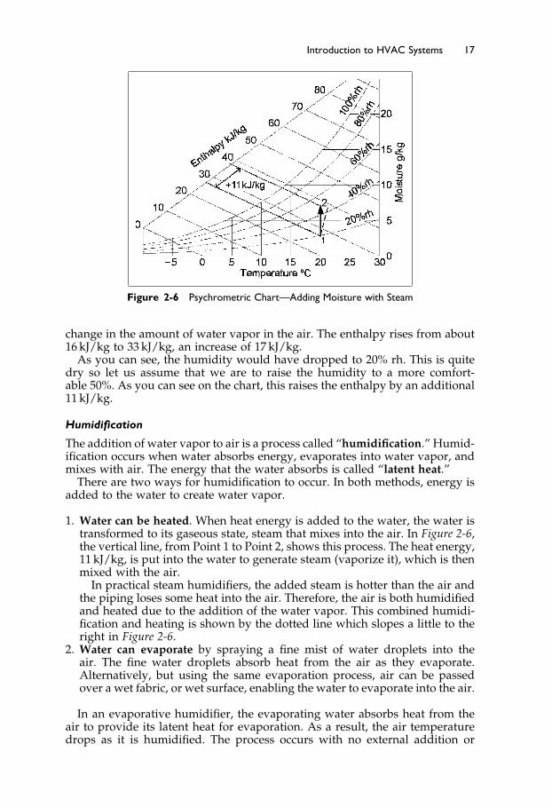
Figure 2-6 Psychrometric Chart—Adding Moisture with Steam
change in the amount of water vapor in the air. The enthalpy rises from about16 kJ/kg to 33 kJ/kg, an increase of 17 kJ/kg.
As you can see, the humidity would have dropped to 20% rh. This is quitedry so let us assume that we are to raise the humidity to a more comfort-able 50%. As you can see on the chart, this raises the enthalpy by an additional11 kJ/kg.
Humidification
The addition of water vapor to air is a process called “humidification.” Humid-ification occurs when water absorbs energy, evaporates into water vapor, andmixes with air. The energy that the water absorbs is called “latent heat.”
There are two ways for humidification to occur. In both methods, energy isadded to the water to create water vapor.
1. Water can be heated. When heat energy is added to the water, the water istransformed to its gaseous state, steam that mixes into the air. In Figure 2-6,the vertical line, from Point 1 to Point 2, shows this process. The heat energy,11 kJ/kg, is put into the water to generate steam (vaporize it), which is thenmixed with the air.
In practical steam humidifiers, the added steam is hotter than the air andthe piping loses some heat into the air. Therefore, the air is both humidifiedand heated due to the addition of the water vapor. This combined humidi-fication and heating is shown by the dotted line which slopes a little to theright in Figure 2-6.
2. Water can evaporate by spraying a fine mist of water droplets into theair. The fine water droplets absorb heat from the air as they evaporate.Alternatively, but using the same evaporation process, air can be passedover a wet fabric, or wet surface, enabling the water to evaporate into the air.
In an evaporative humidifier, the evaporating water absorbs heat from theair to provide its latent heat for evaporation. As a result, the air temperaturedrops as it is humidified. The process occurs with no external addition or

Elsevier UK Ch02-P373998 3-11-2006 7:22a.m. Page:18 Trimsize:6.5×9.5inches
Basal Font:Palatino Margins:Top:40pt Gutter:55pt Font Size:10/11 Text Width:29pc Depth:51 Lines
18 Fundamentals of HVAC
Figure 2-7 Psychrometric Chart—Adding Moisture, Evaporative Humidifier
removal of heat. It is called an adiabatic process. Since there is no changein the heat energy (enthalpy) in the air stream, the addition of moisture, byevaporation, occurs along a line of constant enthalpy.
Figure 2-7 shows the process. From Point 1, the moisture evaporates intothe air and the temperature falls to 9 �C, Point 2. During this evaporation, therelative humidity rises to about 95%. To reach our target of 20 �C and 50% rhwe must now heat the moistened air at Point 2 from 9 �C to 20 �C, Point 3,requiring 11 kJ/kg of dry air.
To summarize, we can humidify by adding heat to water to produce steamand mixing the steam with the air, or we can evaporate the moisture and heatthe moistened air. We achieve the same result with the same input of heat bytwo different methods.
The process of evaporative cooling can be used very effectively in a hot, drydesert climate to pre-cool the incoming ventilation air. For example, outsideair at 35 �C and 15% relative humidity could be cooled to 26 �C by pass-ing it through an evaporative cooler. The relative humidity will rise, butonly to about 40%. Even with no mechanical refrigeration, this results in apleasant reduction in air temperature without raising the relative humidityexcessively.
Cooling and dehumidification
Cooling is most often achieved in an air-conditioning system by passing themoist air over a cooling coil. As illustrated in Figure 2-8, a coil is constructedof a long serpentine pipe through which a cold liquid or gas flows. Thiscold fluid is either chilled water, typically between 4�5 �C and 7�5 �C, or arefrigerant. The pipe is lined with fins to increase the heat transfer from theair to the cold fluid in the pipe. Figure 2-8 shows the face of the coil, inthe direction of airflow. Depending on the coil design, required temperaturedrop, and moisture removal performance, the coil may have 2 to 8 rows ofpiping. Generally the more rows, the higher the moisture removal ability ofthe coil.

Elsevier UK Ch02-P373998 3-11-2006 7:22a.m. Page:19 Trimsize:6.5×9.5inches
Basal Font:Palatino Margins:Top:40pt Gutter:55pt Font Size:10/11 Text Width:29pc Depth:51 Lines
Introduction to HVAC Systems 19
COOLANTFLOW
FACE VIEW OF FINNED COIL SHOWING COOLANT FLOW.
Figure 2-8 Cooling Coil
There are two results. First, the cooling coil cools the air as the air passesover the coils. Second, because the cooling fluid in the coil is usually wellbelow the saturation temperature of the air, moisture condenses on the coil,and drips off, to drain away. This process reduces the enthalpy, or heat, of theair mixture and increases the enthalpy of the chilled water or refrigerant. Inanother part of the system, this added heat must be removed from the chilledwater or refrigerant to recool it for reuse in the cooling coil.
The amount of moisture that is removed depends on several factorsincluding:
• The temperature of the cooling fluid• The depth of the coil• Whether the fins are flat or embossed• The air velocity across the coil.
An example of the typical process is shown in Figure 2-9.
Figure 2-9 Psychrometric Chart—Cooling Across a Wet Cooling Coil
Elsevier UK Ch02-P373998 3-11-2006 7:22a.m. Page:20 Trimsize:6.5×9.5inches
Basal Font:Palatino Margins:Top:40pt Gutter:55pt Font Size:10/11 Text Width:29pc Depth:51 Lines
20 Fundamentals of HVAC
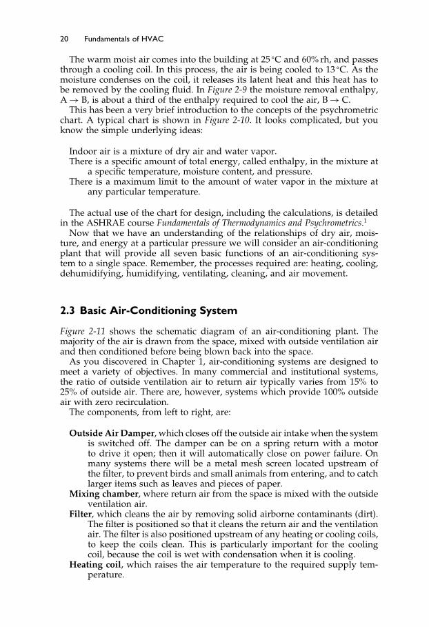
The warm moist air comes into the building at 25 �C and 60% rh, and passesthrough a cooling coil. In this process, the air is being cooled to 13 �C. As themoisture condenses on the coil, it releases its latent heat and this heat has tobe removed by the cooling fluid. In Figure 2-9 the moisture removal enthalpy,A → B, is about a third of the enthalpy required to cool the air, B → C.
This has been a very brief introduction to the concepts of the psychrometricchart. A typical chart is shown in Figure 2-10. It looks complicated, but youknow the simple underlying ideas:
Indoor air is a mixture of dry air and water vapor.There is a specific amount of total energy, called enthalpy, in the mixture at
a specific temperature, moisture content, and pressure.There is a maximum limit to the amount of water vapor in the mixture at
any particular temperature.
The actual use of the chart for design, including the calculations, is detailedin the ASHRAE course Fundamentals of Thermodynamics and Psychrometrics.1
Now that we have an understanding of the relationships of dry air, mois-ture, and energy at a particular pressure we will consider an air-conditioningplant that will provide all seven basic functions of an air-conditioning sys-tem to a single space. Remember, the processes required are: heating, cooling,dehumidifying, humidifying, ventilating, cleaning, and air movement.
2.3 Basic Air-Conditioning System
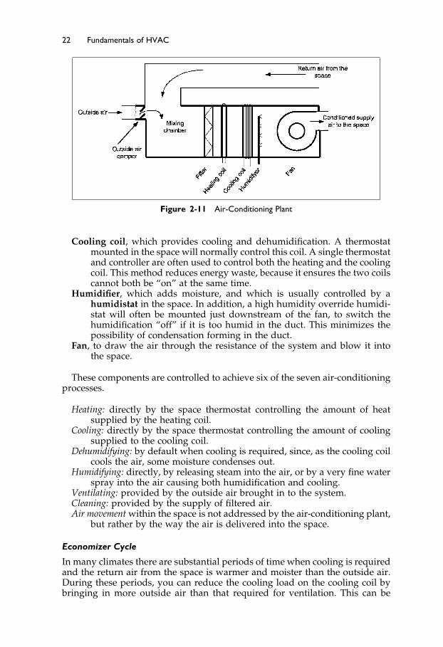
Figure 2-11 shows the schematic diagram of an air-conditioning plant. Themajority of the air is drawn from the space, mixed with outside ventilation airand then conditioned before being blown back into the space.
As you discovered in Chapter 1, air-conditioning systems are designed tomeet a variety of objectives. In many commercial and institutional systems,the ratio of outside ventilation air to return air typically varies from 15% to25% of outside air. There are, however, systems which provide 100% outsideair with zero recirculation.
The components, from left to right, are:
Outside Air Damper, which closes off the outside air intake when the systemis switched off. The damper can be on a spring return with a motorto drive it open; then it will automatically close on power failure. Onmany systems there will be a metal mesh screen located upstream ofthe filter, to prevent birds and small animals from entering, and to catchlarger items such as leaves and pieces of paper.
Mixing chamber, where return air from the space is mixed with the outsideventilation air.
Filter, which cleans the air by removing solid airborne contaminants (dirt).The filter is positioned so that it cleans the return air and the ventilationair. The filter is also positioned upstream of any heating or cooling coils,to keep the coils clean. This is particularly important for the coolingcoil, because the coil is wet with condensation when it is cooling.
Heating coil, which raises the air temperature to the required supply tem-perature.

ElsevierUK
Ch02-P373998
3-11-2006
7:22a.m.
Page:21
Trimsize:6.5×
9.5inches
BasalFont:Palatino
Margins:Top:40pt
Gutter:55pt
FontSize:10/11
TextWidth:29pc
Depth:51Lines
Introductionto
HV
AC
Systems
21Figure 2-10 ASHRAE Psychrometric Chart
Elsevier UK Ch02-P373998 3-11-2006 7:22a.m. Page:22 Trimsize:6.5×9.5inches
Basal Font:Palatino Margins:Top:40pt Gutter:55pt Font Size:10/11 Text Width:29pc Depth:51 Lines
22 Fundamentals of HVAC
Figure 2-11 Air-Conditioning Plant
Cooling coil, which provides cooling and dehumidification. A thermostatmounted in the space will normally control this coil. A single thermostatand controller are often used to control both the heating and the coolingcoil. This method reduces energy waste, because it ensures the two coilscannot both be “on” at the same time.
Humidifier, which adds moisture, and which is usually controlled by ahumidistat in the space. In addition, a high humidity override humidi-stat will often be mounted just downstream of the fan, to switch thehumidification “off” if it is too humid in the duct. This minimizes thepossibility of condensation forming in the duct.
Fan, to draw the air through the resistance of the system and blow it intothe space.
These components are controlled to achieve six of the seven air-conditioningprocesses.
Heating: directly by the space thermostat controlling the amount of heatsupplied by the heating coil.
Cooling: directly by the space thermostat controlling the amount of coolingsupplied to the cooling coil.
Dehumidifying: by default when cooling is required, since, as the cooling coilcools the air, some moisture condenses out.
Humidifying: directly, by releasing steam into the air, or by a very fine waterspray into the air causing both humidification and cooling.
Ventilating: provided by the outside air brought in to the system.Cleaning: provided by the supply of filtered air.Air movement within the space is not addressed by the air-conditioning plant,
but rather by the way the air is delivered into the space.
Economizer Cycle
In many climates there are substantial periods of time when cooling is requiredand the return air from the space is warmer and moister than the outside air.During these periods, you can reduce the cooling load on the cooling coil bybringing in more outside air than that required for ventilation. This can be

Elsevier UK Ch02-P373998 3-11-2006 7:22a.m. Page:23 Trimsize:6.5×9.5inches
Basal Font:Palatino Margins:Top:40pt Gutter:55pt Font Size:10/11 Text Width:29pc Depth:51 Lines
Introduction to HVAC Systems 23
Figure 2-12 Air-Conditioning Plant with Economizer Cycle
accomplished by expanding the design of the basic air-conditioning system toinclude an economizer.
The economizer consists of three (or four) additional components as shownin Figure 2-12.
Expanded air intake and damper, sized for 100% system flow.Relief air outlet with automatic damper, to exhaust excess air to outside.Return air damper, to adjust the flow of return air into the mixing chamber.(Optional) Return fan in the return air duct. The return fan is often added
on economizer systems, particularly on larger systems. If there is noreturn fan, the main supply fan must provide enough positive pressurein the space to force the return air out through any ducting and the reliefdampers. This can cause unacceptable pressures in the space, makingdoors slam and difficult to open. When the return air fan is added itwill overcome the resistance of the return duct and relief damper, sothe space pressure stays near neutral to outside.
Example: Let us consider the operation of the economizer system inFigure 2-13. The particular system operating requirements and settings are:
The system is required to provide supply air at 13 �CReturn air from the space is at 24 �CMinimum outside air requirement is 20%,Above 20 �C, the system will revert to minimum outside air for ventilation.
In Figure 2-13, the outside temperature is shown along the x-axis from −40 �Cto +40 �C. We are going to consider the economizer operation from −40 �C upto 40 �C, working across Figure 2-13 from left to right.
At −40 �C, the minimum 20% outside air for ventilation is mixing with 80%return air at 24 �C and will produce a mixed temperature of only 11�2 �C.Therefore, in order to achieve the required supply air at 13 �C, the heater willhave to increase the temperature by 1�8 �C.

Elsevier UK Ch02-P373998 3-11-2006 7:22a.m. Page:24 Trimsize:6.5×9.5inches
Basal Font:Palatino Margins:Top:40pt Gutter:55pt Font Size:10/11 Text Width:29pc Depth:51 Lines
24 Fundamentals of HVAC
Figure 2-13 Economizer Performance
At −31 �C, the minimum outside air for ventilation, 20%, is mixing with 80%return air at 24 �C to produce a mixed temperature of 13 �C, so the supply airwill no longer require any additional heating.
As the temperature rises above −31 �C the proportion of outside air willsteadily increase to maintain a mixed temperature of 15 �C. When the outsideair temperature reaches 15 �C the mixture will be 100% outside air (and 0%return air). This represents full economizer operation.
Above 15 �C the controls will maintain 100% outside air but the temperaturewill rise as does the outside temperature. The cooling coil will come on to coolthe mixed air to the required 15 �C.
In this example, at 20 �C the controls will close the outside air dampers, andallow only the required 20% ventilation air into the mixing chamber.
From 20 �C to 40 �C the system will be mixing 20% outside air and 80%return air. This will produce a mixture with temperature rising from 23�2 �Cto 27�2 �C as the outside air temperature rises from 20 �C to 40 �C.
The useful economizer operation is from −31 �C to 20 �C. Below −31 �C theeconomizer has no effect, since the system is operating with the minimum20% outside ventilation air intake. In this example, 20 �C was a predeterminedchangeover point. Above 20 �C, the economizer turns off, and the systemreverts to the minimum outside air amount, 20%.
The economizer is a very valuable energy saver for climates with longperiods of cool weather. For climates with warm moist weather most of theyear, the additional cost is not recovered in savings. Also, for spaces wherethe relative humidity must be maintained above ∼ 45%, operation in verycold weather is uneconomic. This is because cold outside air is very dry, andconsiderable supplementary humidification energy is required to humidify theadditional outside air.
2.4 Zoned Air-Conditioning Systems
The air-conditioning system considered so far provides a single source ofair with uniform temperature to the entire space, controlled by one space

Elsevier UK Ch02-P373998 3-11-2006 7:22a.m. Page:25 Trimsize:6.5×9.5inches
Basal Font:Palatino Margins:Top:40pt Gutter:55pt Font Size:10/11 Text Width:29pc Depth:51 Lines
Introduction to HVAC Systems 25
thermostat and one space humidistat. However, in many buildings there are avariety of spaces with different users and varying thermal loads. These varyingloads may be due to different inside uses of the spaces, or due to changes incooling loads because the sun shines into some spaces and not others. Thusour simple system, which supplies a single source of heating or cooling, mustbe modified to provide independent, variable cooling or heating to each space.
When a system is designed to provide independent control in differentspaces, each space is called a “zone.” A zone may be a separate room. A zonemay also be part of a large space. For example, a theatre stage may be a zone,while the audience seating area is a second zone in the same big space. Eachhas a different requirement for heating and cooling.
This need for zoning leads us to the four broad categories of air-conditioningsystems, and consideration of how each can provide zoned cooling and heating.The four systems are
1. All-air systems2. Air-and-water systems3. All-water systems4. Unitary, refrigeration-based systems.
System 1: All-air systems
All-air systems provide air conditioning by using a tempered flow of air tothe spaces. These all-air systems need substantial space for ducting the air toeach zone.
The cooling or heating capacity, Q, is measured in Joules or Watts and isthe product of airflow, measured in cubic meters per second �m3/s�, times thedifference in temperature between the supply air to the zone and the returnair from the zone.
Q = Constant · mass flow · temperature difference
Q (Joules) = Constant for Joules · m3/s · ��Czone −� Csupply air�
Q (Watts) = Constant for Watts · m3/s · ��Czone −� Csupply air�
To change the heating or cooling capacity of the air supply to one zone, thesystem must either alter the supply temperature, �C, or alter the flow, m3/s, tothat zone.
Reheat system: The simplest, and least energy efficient system, is the constantvolume reheat system. Let us assume that the main air system provides airthat is cool enough to satisfy all possible cooling loads, and that there is aheater in the duct to each zone.
A zone thermostat can then control the heater to maintain the desired zonesetpoint temperature. The system, shown in Figure 2-14, is called a reheat sys-tem, since the cool air is reheated as necessary to maintain zone temperature.
Figure 2-14 illustrates the basic air-conditioning system, plus ducting, to onlytwo of many zones. The air to each zone passes over a reheat coil beforeentering the zone. A thermostat in the zone controls the reheat coil. If the zonerequires full cooling, the thermostat will shut off the reheat coil. Then, as thecooling load drops, the thermostat will turn on the coil to maintain the zonetemperature.
Elsevier UK Ch02-P373998 3-11-2006 7:22a.m. Page:26 Trimsize:6.5×9.5inches
Basal Font:Palatino Margins:Top:40pt Gutter:55pt Font Size:10/11 Text Width:29pc Depth:51 Lines
26 Fundamentals of HVAC
T T
REHEAT COILS
Figure 2-14 Reheat System
T T
VARIABLE VOLUMEDAMPERS
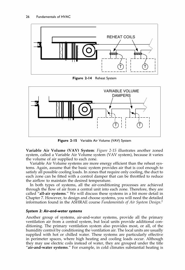
Figure 2-15 Variable Air Volume (VAV) System
Variable Air Volume (VAV) System: Figure 2-15 illustrates another zonedsystem, called a Variable Air Volume system (VAV system), because it variesthe volume of air supplied to each zone.
Variable Air Volume systems are more energy efficient than the reheat sys-tems. Again, assume that the basic system provides air that is cool enough tosatisfy all possible cooling loads. In zones that require only cooling, the duct toeach zone can be fitted with a control damper that can be throttled to reducethe airflow to maintain the desired temperature.
In both types of systems, all the air-conditioning processes are achievedthrough the flow of air from a central unit into each zone. Therefore, they arecalled “all-air systems.” We will discuss these systems in a bit more detail inChapter 7. However, to design and choose systems, you will need the detailedinformation found in the ASHRAE course Fundamentals of Air System Design.2
System 2: Air-and-water systems
Another group of systems, air-and-water systems, provide all the primaryventilation air from a central system, but local units provide additional con-ditioning. The primary ventilation system also provides most, or all, of thehumidity control by conditioning the ventilation air. The local units are usuallysupplied with hot or chilled water. These systems are particularly effectivein perimeter spaces, where high heating and cooling loads occur. Althoughthey may use electric coils instead of water, they are grouped under the title“air-and-water systems.” For example, in cold climates substantial heating is

Elsevier UK Ch02-P373998 3-11-2006 7:22a.m. Page:27 Trimsize:6.5×9.5inches
Basal Font:Palatino Margins:Top:40pt Gutter:55pt Font Size:10/11 Text Width:29pc Depth:51 Lines
Introduction to HVAC Systems 27
often required at the perimeter walls. In this situation, a hot-water-heatingsystem can be installed around the perimeter of the building while a centralair system provides cooling and ventilation.
System 3: All-water systems
When the ventilation is provided through natural ventilation, by openingwindows, or other means, there is no need to duct ventilation air to thezones from a central plant. This allows all processes other than ventilationto be provided by local equipment supplied with hot and chilled waterfrom a central plant. These systems are grouped under the name “all-watersystems.”
The largest group of all-water systems are heating systems. We will intro-duce these systems, pumps and piping in Chapters 8 and 9. The detailed designof these heating systems is covered in the ASHRAE course Fundamentals ofHeating Systems.3
Both the air-and-water and all-water systems rely on a central supply of hotwater for heating and chilled water for cooling. The detailed designs and cal-culations for these systems can be found in the ASHRAE course Fundamentalsof Water System Design.4
System 4: Unitary, refrigerant-based systems
The final type of system uses local refrigeration equipment and heaters toprovide air conditioning. They are called “unitary refrigerant–based systems”and we will discuss them in more detail in Chapter 6.
The window air-conditioner is the simplest example of this type of system.In these systems, ventilation air may be brought in by the unit, by openingwindows, or from a central ventilation air system.
The unitary system has local refrigerant-based cooling. In comparison,the other types of systems use a central refrigeration unit to either coolthe air-conditioning airflow or to chill water for circulation to local coolingunits.
The design, operation and choice of refrigeration equipment is a huge fieldof knowledge in itself. Refrigeration equipment choices, design, installation,and operating issues are introduced in the ASHRAE course Fundamentals ofRefrigeration.5
System Control
We have not yet considered how any of these systems can be controlled.Controls have become a vast area of knowledge with the use of solid-statesensors, computers, radio, and the Internet. Basic concepts will be introducedthroughout this text, with a focused discussion in Chapter 11. For an in-depthintroduction to controls, ASHRAE provides the course Fundamentals of HVACControl Systems.6
2.5 Choosing an Air-Conditioning System
Each of the four general types of air-conditioning systems has numerous vari-ations, so choosing a system is not a simple task. With experience, it becomes

Elsevier UK Ch02-P373998 3-11-2006 7:22a.m. Page:28 Trimsize:6.5×9.5inches
Basal Font:Palatino Margins:Top:40pt Gutter:55pt Font Size:10/11 Text Width:29pc Depth:51 Lines
28 Fundamentals of HVAC
easier. However, a new client, a new type of building, or a very differentclimate can be a challenge.
We are now going to briefly outline the range of factors that affect systemchoice and finish by introducing a process that designers can use to help choosea system.
The factors, or parameters that influence system choice can conveniently bedivided into the following groups:
• Building design• Location issues• Utilities: availability and cost• Indoor requirements and loads• Client issues.
Building Design
The design of the building has a major influence on system choice. For example,if there is very little space for running ducts around the building, an all-airsystem may not fit in the available space.
Location Issues
The building location determines the weather conditions that will affect thebuilding and its occupants. For the specific location we will need to considerfactors like:
site conditionspeak summer cooling conditionssummer humiditypeak winter heating conditionswind speedssunshine hourstypical snow accumulation depths.
The building location and, at times, the client, will determine what national,local, and facility specific codes must be followed. Typically, the designer mustfollow the local codes. These include:
Building code that includes a section on HVAC design including ventilation.Fire code that specifies how the system must be designed to minimize the
start and spread of fire and smoke.Energy code that mandates minimum energy efficiencies for the building and
components. We will be considering the ASHRAE Standard 90.1-2004,Energy Standard for Buildings Except Low-Rise Residential Buildings,7 andother energy conservation issues in Chapter 12.
In addition, some types of buildings, such as medical facilities, are designedto consensus codes which may not be required by local authorities butwhich may be mandated by the client. An example is The American Insti-tute of Architects Guidelines for Design and Construction of Hospital and HealthCare Facilities,8 which has guidelines that are extremely onerous in someclimates.
Elsevier UK Ch02-P373998 3-11-2006 7:22a.m. Page:29 Trimsize:6.5×9.5inches
Basal Font:Palatino Margins:Top:40pt Gutter:55pt Font Size:10/11 Text Width:29pc Depth:51 Lines
Introduction to HVAC Systems 29
Utilities: Availability and Cost
The choice of system can be heavily influenced by available utilities and theircosts to supply and use. So, if chilled water is available from the adjacentbuilding, it would probably be cost advantageous to use it, rather than installnew unitary refrigerant-based units in the new building.
Then again, the cost of electricity may be very high at peak periods, encour-aging the design of an electrically efficient system with low peak-demandfor electricity. We will be introducing some of the ways to limit the cost ofpeak-time electricity in our final chapter, Chapter 13.
The issues around electrical pricing and usage have become very well publi-cized in North America over recent years. The ASHRAE course, Fundamentalsof Electrical Systems and Building Electrical Energy Use,10 introduces this topic.
Indoor Requirements and Loads
The location effects and indoor requirements provide all the necessary infor-mation for load calculation for the systems.
The thermal and moisture loads – Occupants’ requirements and heat outputfrom lighting and equipment affect the demands on the air-conditioningsystem.
Outside ventilation air – The occupants and other polluting sources, suchas cooking, will determine the requirements.
Zoning – The indoor arrangement of spaces and uses will determine if, andhow, the system is to be zoned.
Other indoor restrictions may be very project, or even zone specific. Forexample, a sound recording studio requires an extremely quiet system andnegligible vibration.
The methods of calculating the heating and cooling loads are fully explained,with examples, in the ASHRAE course Fundamentals of Heating and CoolingLoads.9
Client Issues
Buildings cost money to construct and to use. Therefore, the designer has toconsider the clients’ requirements both for construction and for in-use costs.For example, the available construction finances may dictate a very simplesystem. Alternatively, the client may wish to finance a very sophisticated, andmore expensive system to achieve superior performance, or to reduce in-usecosts.
In addition to cost structures, the availability of maintenance staff mustbe considered. A building at a very remote site should have simple, reliablesystems, unless very competent and well-supported maintenance staff will beavailable.
Clients’ approvals may be gained, or lost, based on their own previousexperience with other projects or systems. Therefore, it is important for thedesigner to find out, in advance, if the client has existing preconceptions aboutpotential systems.
System Choice
While all the above factors are considered when choosing a system, the firststep in making a choice is to calculate the system loads and establish the

Elsevier UK Ch02-P373998 3-11-2006 7:22a.m. Page:30 Trimsize:6.5×9.5inches
Basal Font:Palatino Margins:Top:40pt Gutter:55pt Font Size:10/11 Text Width:29pc Depth:51 Lines
30 Fundamentals of HVAC
number and size of the zones. Understanding of the loads may eliminate somesystems from consideration. For example:
• In warm climates where heating is not required only systems providingcooling need be considered.
• If there are significant variations in operating hours between zones, a systemwhich cannot be shut down on a zone-by-zone basis may not be worthconsidering.
Typically, after some systems have been eliminated for specific reasons, oneneeds to do a point-by-point comparison to make a final choice. This is wherethe system-choice matrix is a very useful tool.
2.6 System Choice Matrix
The matrix method of system choice consists of a list of relevant factors thataffect system choice and a tabular method of comparing the systems underconsideration.
Figure 2-16 provides an illustration of the matrix method of choosing asystem. In the left column of the matrix are the relevant factors that willbe used to evaluate the systems, and the top row shows the systems underconsideration.
In our example, we have simplified the matrix in both dimensions. We havestrictly limited our relevant factors, and we have limited our choices downto two systems, the reheat system and a VAV system. Note that in a realmatrix you would include all the relevant issues, as discussed in the precedingsection. You would also probably have several systems under consideration.
In this example, the relevant design issues for this building are as follows:
• The building requires cooling but no heating.• Some areas of the building will be in use for 24 hours every day of the week.
Other areas will be used just during the day, Monday to Friday.• The client has indicated that operational expenses (ongoing) are more impor-
tant than construction costs (one time).
System 1Reheat
System 2 Variable Air Volume
RelativeImportance
Relative Performance
RelativeScore
Relative Performance
Relative Score
Cooling Capacity 8 10 80 10 80
Temperature Control 9 10 90 8 72
Zone Occupancy Timing 10 1 10 9 90
First Cost 5 7 35 5 25
Operating Cost 8 3 24 8 64
Totals 239 331
Figure 2-16 Matrix for Systems Choice

Elsevier UK Ch02-P373998 3-11-2006 7:22a.m. Page:31 Trimsize:6.5×9.5inches
Basal Font:Palatino Margins:Top:40pt Gutter:55pt Font Size:10/11 Text Width:29pc Depth:51 Lines
Introduction to HVAC Systems 31
As you can see, the matrix has a list of relevant issues down the left handside. Each issue may have a greater or lesser importance. In the column headed“Relative importance” one assigns a multiplier between 1 and 10, with 10meaning “extremely important” and 1 meaning “not important.” So if, forour example, temperature control is very important it might be rated “9” andthe ability to Zone—which is critical to economic operation in this particularbuilding, requires a relative importance of 10. As you can see in the matrix, itis possible for two factors to share the same relative importance.
Once the relative importances have been assigned, it is time to assess thesystems under consideration. In our example, both systems have excellentcooling capacity. They each score “10” under performance for this factor.
When we consider the requirement for zone occupancy-timing, however,we note that the reheat system does not have any ability to shut off one partof the system and leave another running. Therefore, it scores only “1” for thisrequirement. The VAV system, on the other hand, has the capacity to shut offany zone at any time though the main fan still has to run, even if only onezone is on. Therefore the VAV system scores “9” for this factor.
The VAV system also gets a higher score for first cost (construction cost)and for operating expense.
After each factor has been considered, the “relative performance” number ismultiplied by the “relative importance” multiplier, to obtain the relative scorefor that item. The results for each system are totaled, and compared.
In this example, the VAV has a higher score and would be chosen.The method is an excellent way of methodically assessing system alterna-
tives. However, it should be used intelligently. If a system fails on a criticalrequirement, it should be eliminated, even if its total score may be the highest.For example, on a prison project, one would likely exclude any system thatrequires maintenance from the cells, regardless of how high it scored on amatrix!
For a more complete listing of issues for use in a matrix see Chapter 1 ofthe 2004 ASHRAE Handbook—Systems and Equipment,11 and for information onoperating and other costs see Chapter 35 in the 2003 ASHRAE Handbook—Applications Handbook.12
The Next Step
Having introduced systems and the range of design issues, the next twochapters will cover two specific subjects which dictate design requirements:Thermal Comfort in Chapter 3, and Ventilation and Indoor Air Quality inChapter 4.
Summary
2.2 The Psychrometric Chart
The psychrometric chart is a visual aid that demonstrates the relationships ofair temperature, moisture content, and energy. It is built upon three simpleconcepts:
Indoor air is a mixture of dry air and water vapor.

Elsevier UK Ch02-P373998 3-11-2006 7:22a.m. Page:32 Trimsize:6.5×9.5inches
Basal Font:Palatino Margins:Top:40pt Gutter:55pt Font Size:10/11 Text Width:29pc Depth:51 Lines
32 Fundamentals of HVAC
At any given temperature, there is a maximum amount of water vapor thatthe mixture can sustain. The saturation line represents this maximum. Whenmoist air is cooled to a temperature below the saturation line, the water vaporcondenses, and the air is dehumidified. The addition of water to air is calledhumidification. This occurs when water absorbs energy, evaporates into watervapor and mixes with air. Humidification can take place when water is heated,to produce steam that mixes into the air, or when water evaporates into the air.Evaporation occurs with no external addition or removal of heat. It is called an“adiabatic process.” The energy that the water vapor absorbs as it evaporatesis referred to as its “latent heat.”
There is a specific amount of energy in the dry air/water vapor mixture at aspecific temperature and pressure. The energy of this mixture, at a particularpressure, is dependent on two measures: the temperature of the air, and thequantity of water vapor in the air. The total energy of the air/water vapormixture is called “Enthalpy.” The unit measure for enthalpy is kilojoules perkilogram of dry air, abbreviated as kJ/kg.
2.3 The components of a Basic Air-Conditioning System
These include the outside air damper, the mixing chamber, the filter, theheating coil, the cooling coil, the humidifier and the fan. These componentsare controlled to achieve six of the seven air-conditioning processes: heating,humidifying, cooling, dehumidifying, ventilating, and cleaning.
The economizer cycle is an energy saver for climates with long periodsof cool weather. The economizer consists of three, or four additional com-ponents: expanded air intake and damper sized for 100% flow; relief outletwith damper to exhaust excess air to outside; return air damper to adjust theflow of return air into the mixing chamber; (optional) return fan in the returnair duct.
2.4 Zoned Air-Conditioning Systems
Zoning is used to provide variable heating or cooling in different spaces using:all-air systems, like reheat and variable air volume systems; air-and-watersystems, all-water systems, and unitary, refrigeration-based systems.
2.5 Choosing an Air-Conditioning System
Design factors for choosing an air-conditioning system include: buildingdesign, location issues, utilities – availability and cost, indoor requirementsand loads, and client issues.
2.6 System Choice Matrix
To determine the relative importance of the different design factors, youcan use a System Choice Matrix to compare the systems that are underconsideration.

Elsevier UK Ch02-P373998 3-11-2006 7:22a.m. Page:33 Trimsize:6.5×9.5inches
Basal Font:Palatino Margins:Top:40pt Gutter:55pt Font Size:10/11 Text Width:29pc Depth:51 Lines
Introduction to HVAC Systems 33
Bibliography
1. ASHRAE. 1998. Fundamentals of Thermodynamics and Psychrometrics. Atlanta: Amer-ican Society of Heating, Refrigerating and Air-Conditioning Engineers, Inc.
2. ASHRAE. 1998. Fundamentals of Air System Design. Atlanta: American Society ofHeating, Refrigerating and Air-Conditioning Engineers, Inc.
3. ASHRAE.1998. Fundamentals of Heating Systems. Atlanta: American Society of Heat-ing, Refrigerating and Air-Conditioning Engineers, Inc.
4. ASHRAE. 1998. Fundamentals of Water System Design. Atlanta: American Society ofHeating, Refrigerating and Air-Conditioning Engineers, Inc.
5. ASHRAE. 1999. Fundamentals of Refrigeration. Atlanta: American Society of Heating,Refrigerating and Air-Conditioning Engineers, Inc.
6. ASHRAE. 1998. Fundamentals of HVAC Control Systems. Atlanta: American Societyof Heating, Refrigerating and Air-Conditioning Engineers, Inc.
7. ASHRAE. 2004. ASHRAE Standard 90.1-2004, Energy Standard for Buildings ExceptLow-Rise Residential Buildings. Atlanta: American Society of Heating, Refrigeratingand Air-Conditioning Engineers, Inc.
8. AIA. 2001. Guidelines for Design and Construction of Hospital and Health Care Facilities.Washington, D.C.: The American Institute of Architects.
9. ASHRAE. 1998. Fundamentals of Heating and Cooling Loads. Atlanta: American Societyof Heating, Refrigerating and Air-Conditioning Engineers, Inc.
10. ASHRAE. 1998. Fundamentals of Electrical Systems and Building Electrical Energy Use.Atlanta: American Society of Heating, Refrigerating and Air-Conditioning Engi-neers, Inc.
11. ASHRAE. 2004. 2004 ASHRAE Handbook—HVAC Systems and Equipment. Atlanta:American Society of Heating, Refrigerating and Air-Conditioning Engineers, Inc.
12. ASHRAE. 2003. 2003 ASHRAE Handbook—HVAC Applications. Atlanta: AmericanSociety of Heating, Refrigerating and Air-Conditioning Engineers, Inc.
Elsevier UK Ch03-P373998 3-11-2006 7:23a.m. Page:34 Trimsize:6.5×9.5inches
Basal Font:Palatino Margins:Top:40pt Gutter:55pt Font Size:10/11 Text Width:29pc Depth:51 Lines
Chapter 3
Thermal Comfort
Contents of Chapter 3
InstructionsObjectives of Chapter 33.1 Introduction: What is Thermal Comfort?3.2 Seven Factors Influencing Thermal Comfort3.3 Conditions for Comfort3.4 Managing Under Less Than Ideal Conditions3.5 Requirements of Non-Standard GroupsThe Next StepSummaryBibliography
Instructions
Review Sections 1.6.1 and 1.6.2 for a discussion of the factors that affect humancomfort.
Read the chapter. Re-read the parts of the chapter that are emphasized inthe summary.
Objectives of Chapter 3
Having studied this chapter you should be able to:
List seven factors influencing thermal comfort.Explain why thermal comfort depends on the individual as well as the
thermal conditions.Choose acceptable thermal design conditions.
3.1 Introduction: What is Thermal Comfort?
In Chapter 1, Sections 1.6.1 and 1.6.2, we introduced the Personal Environ-mental Model that illustrated the main factors that affect human comfort in anenvironment. In this chapter, we will focus only on those specific factors thataffect thermal comfort.

Elsevier UK Ch03-P373998 3-11-2006 7:23a.m. Page:35 Trimsize:6.5×9.5inches
Basal Font:Palatino Margins:Top:40pt Gutter:55pt Font Size:10/11 Text Width:29pc Depth:51 Lines
Thermal Comfort 35
Thermal comfort is primarily controlled by a building’s heating, ventilatingand air-conditioning systems, though the architectural design of the buildingmay also have significant influences on thermal comfort.
This chapter is largely based on ASHRAE Standard 55-2004, Thermal Environ-mental Conditions for Human Occupancy.1 In this text, we will abbreviate the titleto “Standard 55.” For a much more in-depth discussion of thermal comfort andthe way experimental results are presented, see Chapter 8 of the 2005 ASHRAEHandbook—Fundamentals.2
Standard 55 defines thermal comfort as “that condition of mind whichexpresses satisfaction with the thermal environment and is assessed by subjec-tive evaluation.” There is no way “state of mind” can be measured. As a result,all comfort data are based on researchers asking questions about particular sit-uations, to build a numerical model of comfort conditions. The model is basedon answers to questions by many people under many different experimentalconditions.
In the next section, we will consider seven factors influencing comfort andthen define acceptable thermal comfort conditions.
3.2 Seven Factors Influencing Thermal Comfort
You are a person, so you already know a lot about thermal comfort. You havea lifetime of experience. You know that physical exertion makes you “hot andsweaty.” You know you can be more comfortable in a cooler space if you wearmore clothes, or warmer clothes. You know that the air temperature mattersand that the radiant heat from a fire can help keep you warm and comfortable.You have likely experienced feeling hot in a very humid space and been awareof a cold draft. You have anticipated that a space will be warm and comfortableor cool and comfortable when you get inside.
As a result, you have personal experience of the seven factors that affectthermal comfort.
Personal
1. Activity level2. Clothing
Individual Characteristics
3. Expectation
Environmental Conditions and Architectural Effects
4. Air temperature5. Radiant temperature6. Humidity7. Air speed.
1. Activity Level
The human body continuously produces heat through a process call“metabolism.” This heat must be emitted from the body to maintain a fairly

Elsevier UK Ch03-P373998 3-11-2006 7:23a.m. Page:36 Trimsize:6.5×9.5inches
Basal Font:Palatino Margins:Top:40pt Gutter:55pt Font Size:10/11 Text Width:29pc Depth:51 Lines
36 Fundamentals of HVAC
constant core temperature, and ideally, a comfortable skin temperature. Weproduce heat at a minimum rate when asleep. As activity increases, fromsitting to walking to running, so the metabolic heat produced increases.
The standard measure of activity level is the “met.” One met is the metabolicrate (heat output per unit area of skin) for an individual who is seated andat rest. Typical activity levels and the corresponding met values are shown inFigure 3-1.
2. Clothing
In occupied spaces, clothing acts as an insulator, slowing the heat loss fromthe body. As you know from experience, if you are wearing clothing thatis an effective insulator, you can withstand, and feel comfortable in lowertemperatures. To predict thermal comfort we must have an idea of the clothingthat will be worn by the occupants.
Due to the large variety of materials, weights, and weave of fabrics, cloth-ing estimates are just rough estimates. Each article has an insulating value,unit “clo.”
For example: a long-sleeved sweat shirt is 0.34 clo, straight trousers (thin)are 0.15 clo, light underwear is 0.04 clo, ankle-length athletic socks are 0.02 clo,and sandals are 0.02 clo. These clo values can be added to give an overallclothing insulation value. In this case, the preceding set of clothes has anoverall clothing insulation value of 0.57 clo.
Typical values for clothing ensembles are shown in Figure 3-2. All includeshoes, socks, and light underwear.
Later in this chapter we will introduce a chart, Figure 3-4, that illustratescomfortable conditions with 0.5 clo and 1.0 clo. As you can see from Figure 3-2,0.5 clo is very light clothing, and 1.0 clo is heavy indoor clothing.
3. Occupants’ Expectations
People’s expectations affect their perception of comfort in a building. Considerthe following three scenarios that all occur on a very hot day:
• A person walks into an air-conditioned office building. The person expectsthe building to be thermally comfortable.
Activity met* Sleeping 0.7
Reading or writing, seated in office 1.0
Filing, standing in office 1.4
Walking about in office 1.7
Walking 2 mph 2.0
Housecleaning 2.0 to 3.4
Dancing, social 2.4 to 4.4
Heavy machine work 4.0
Figure 3-1 Typical Metabolic Heat Generation for Various Activities (Standard 55,Normative Appendix A, Extracted data) �∗1met = 50kcal/�h ·m2��

Elsevier UK Ch03-P373998 3-11-2006 7:23a.m. Page:37 Trimsize:6.5×9.5inches
Basal Font:Palatino Margins:Top:40pt Gutter:55pt Font Size:10/11 Text Width:29pc Depth:51 Lines
Thermal Comfort 37
Ensemble Description clo* Trouser, short sleeve shirt 0.57 Knee-length skirt, short-sleeve shirt (sandals) 0.54 Trousers, long-sleeved shirt, suit jacket 0.96
Knee-length skirt, long-sleeved shirt, half slip, panty hose, long-sleeved sweater 1.10
Long-sleeved coveralls, T-shirt 0.72
Figure 3-2 Typical Insulation Values for Clothing Ensembles (Standard 55, Appendix B,Table B-1, extracted data) �∗1clo = 0�155m2 ·K/W�
• A person walks into a prestigious hotel. The person expects it to be cool,regardless of the outside temperature.
• A person walks into an economical apartment building with obvious naturalventilation and open windows. The person has lower expectations for acool environment. The person anticipates, even hopes, that it will be coolerinside, but not to the same extent as the air-conditioned office building or thehotel.
Standard 55 recognizes that the expectations for thermal comfort aresignificantly different in buildings where the occupants control openingwindows, as compared to a mechanically cooled building. To address thisdifference, Standard 55 provides different criteria for naturally ventilated build-ings, as compared to the criteria for mechanically cooled, air-conditionedbuildings.
This difference in expectations also shows up in buildings where occu-pants have a thermostat to control their zone. In general, if occupants havea thermostat in their space, they are more satisfied with their space, evenwhen the performance of the thermostat is very restricted or non-existent(dummy thermostat). This is discussed in Section 3.3, “Conditions forComfort.”
4. Air Temperature
When we are referring to air temperature in the context of thermal comfort,we are talking about the temperature in the space where the person is located.This temperature can vary from head to toe and can vary with time.
5. Radiant Temperature
Radiant heat is heat that is transmitted from a hotter body to a cooler body withno effect on the intervening space. An example of radiant heat transfer occurswhen the sun is shining on you. The radiant temperature is the temperatureat which a black sphere would emit as much radiant heat as it received fromits surroundings.
In an occupied space, the floor, walls, and ceiling may be at a temperaturethat is very close to the air temperature. For internal spaces, where the temper-ature of the walls, floor, and ceiling are almost the same as the air temperature,
Elsevier UK Ch03-P373998 3-11-2006 7:23a.m. Page:38 Trimsize:6.5×9.5inches
Basal Font:Palatino Margins:Top:40pt Gutter:55pt Font Size:10/11 Text Width:29pc Depth:51 Lines
38 Fundamentals of HVAC
the radiant temperature will be constant in all directions and virtually thesame as the air temperature.
When a person is sitting close to a large window on a cold, cloudy, winterday, the average radiant temperature may be significantly lower than the airtemperature. Similarly, in spaces with radiant floors or other forms of radiantheating, the average radiant temperature will be above the air temperatureduring the heating season.
6. Humidity
Low humidity: We know that, for some people, low humidity can causespecific problems, like dry skin, dry eyes, and static electricity. However,low humidity does not generally cause thermal discomfort. Standard 55 doesnot define minimum humidity as an issue of thermal discomfort, nor does itaddress those individuals who have severe responses to low humidity.
High humidity: Standard 55 does define the maximum humidity ratio forcomfort at 0.012 kg/kg which is also 12 g/kg. This level of moisture in the aircan also cause serious mold problems in the building and to its contents, sinceit is equivalent to 100% relative humidity at 17 �C.
7. Air Speed
The higher the air speed over a person’s body, the greater the cooling effect.Air velocity that exceeds 0.2 meters per second (m/s), or cool temperaturescombined with any air movement, may cause discomfort—a draft. Drafts aremost noticeable when they blow across the feet and/or the head level, becauseindividuals tend to have less protection from clothing in these areas of theirbody.
3.3 Conditions for Comfort
Standard 55 deals with indoor thermal comfort in normal living environmentsand office-type environments. It does not deal with occupancy periods of lessthan 15 minutes.
The Standard recognizes that individual perceptions of comfort can be sig-nificantly modified by prior exposure. For example, consider people cominginto a building that is air-conditioned to 28 �C on a very hot day, when itis 40 �C outside. The building is obviously cooler as they enter it, a pleasantexperience. After they have been in the building for half an hour, they willhave adjusted and will probably consider the building excessively warm.
When considering issues of comfort, the Standard addresses two situations:
1. Buildings with occupant-operable windows2. Buildings with mechanically conditioned spaces.
Situation 1: Buildings with Occupant-Operable Windows
People behave differently when they have windows they can control. Theyhave different, less demanding, expectations due to their knowledge of the

Elsevier UK Ch03-P373998 3-11-2006 7:23a.m. Page:39 Trimsize:6.5×9.5inches
Basal Font:Palatino Margins:Top:40pt Gutter:55pt Font Size:10/11 Text Width:29pc Depth:51 Lines
Thermal Comfort 39
Figure 3-3 Acceptable Operative Temperature Ranges for Naturally Conditioned Spaces(Standard 55, Figure 5.3)
external environment and their control over the windows. They will alsochoose how they dress, knowing that the building temperatures will be signif-icantly influenced by external temperatures.
Figure 3-3, shows the acceptable range of “indoor operative temperatures”plotted against “mean monthly air temperature” for
Activity levels of 1.0 to 1.3 metPerson not in direct sunlightAir velocity below 0.2 m/sNo specific clothing ensemble values
This acceptable range is called the comfort envelope.The indoor operative temperature is the average of the air temperature and
radiant temperature.The mean monthly outdoor temperature is the average of the hourly temper-
atures; data is normally available from government environmental-monitoringdepartments.
The chart only goes down to a mean monthly temperature of 10 �C,indicating that operant-controlled windows (opening windows) do not pro-vide acceptable thermal comfort conditions in cooler climates during thewinter.
The plot shows the range of comfortable operative temperatures for 80%acceptability, the normal situation, and a narrower comfort band that willprovide a higher standard of comfort, 90% acceptability. For example, for alocation with a maximum summer mean-monthly temperature of 20 �C, therange for 80% acceptability is between 20�5 �C and 27�5 �C.
Note that the normal situation suggests that 20% of the occupants, or 1 in 5,will not find the thermal conditions acceptable!
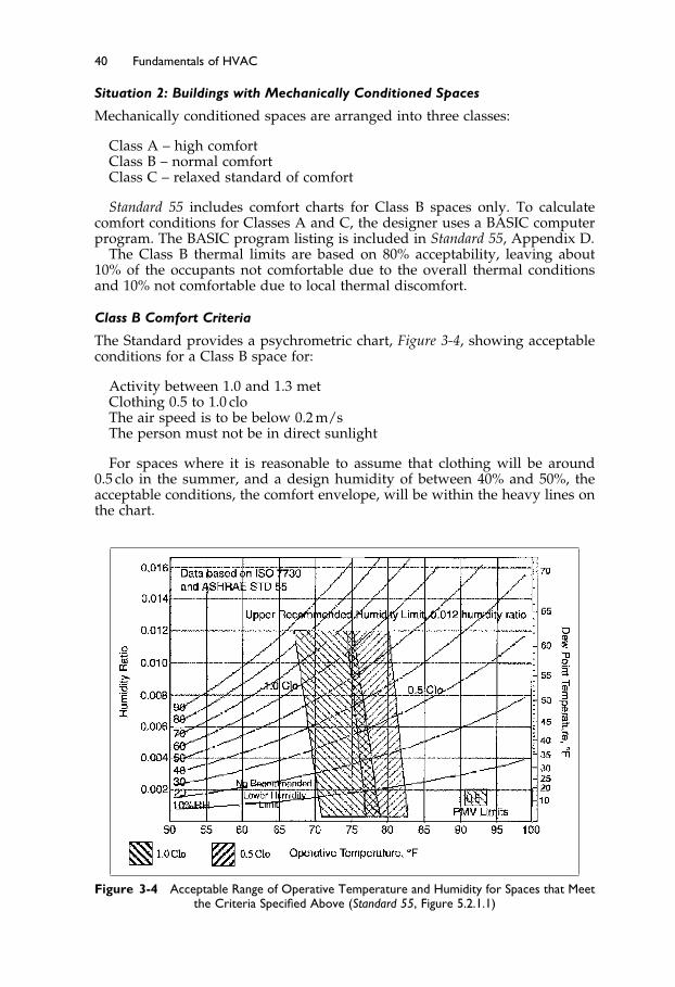
Elsevier UK Ch03-P373998 3-11-2006 7:23a.m. Page:40 Trimsize:6.5×9.5inches
Basal Font:Palatino Margins:Top:40pt Gutter:55pt Font Size:10/11 Text Width:29pc Depth:51 Lines
40 Fundamentals of HVAC
Situation 2: Buildings with Mechanically Conditioned Spaces
Mechanically conditioned spaces are arranged into three classes:
Class A – high comfortClass B – normal comfortClass C – relaxed standard of comfort
Standard 55 includes comfort charts for Class B spaces only. To calculatecomfort conditions for Classes A and C, the designer uses a BASIC computerprogram. The BASIC program listing is included in Standard 55, Appendix D.
The Class B thermal limits are based on 80% acceptability, leaving about10% of the occupants not comfortable due to the overall thermal conditionsand 10% not comfortable due to local thermal discomfort.
Class B Comfort Criteria
The Standard provides a psychrometric chart, Figure 3-4, showing acceptableconditions for a Class B space for:
Activity between 1.0 and 1.3 metClothing 0.5 to 1.0 cloThe air speed is to be below 0.2 m/sThe person must not be in direct sunlight
For spaces where it is reasonable to assume that clothing will be around0.5 clo in the summer, and a design humidity of between 40% and 50%, theacceptable conditions, the comfort envelope, will be within the heavy lines onthe chart.
Figure 3-4 Acceptable Range of Operative Temperature and Humidity for Spaces that Meetthe Criteria Specified Above (Standard 55, Figure 5.2.1.1)
Elsevier UK Ch03-P373998 3-11-2006 7:23a.m. Page:41 Trimsize:6.5×9.5inches
Basal Font:Palatino Margins:Top:40pt Gutter:55pt Font Size:10/11 Text Width:29pc Depth:51 Lines
Thermal Comfort 41
Remember that the chart is for 80% acceptability, although ideally 100%of the occupants would find the conditions thermally acceptable. The occu-pants do have some limited flexibility with clothing in most situations. Theideal situation, but prohibitively expensive in most cases, is to provide all theoccupants with their own temperature control.
Example 1: Let us suppose we wish to minimize the size of the air-conditioningplant; then we could choose design conditions of 27 �C at 50% relativehumidity (rh), and 28 �C at 40% rh. It must be recognized that when thedesigner designs on the limit, it means that more people are likely to beuncomfortable than if the designer chooses to design for the center of thecomfort temperature band.
Example 2: Let us consider a different situation, a prestige office buildingwith, at the design stage, unknown tenants. Here we should allow for bothlight dress and full suits, the full range 0.5 to 1.0 clo. If the design relative-humidity is to be 50%, then we should select the area of overlap and choose24�5 �C as our design temperature.
Example 3: As a third example let us consider a desert town with an outsidedesign-condition of 35 �C and 20% relative humidity. If we pass the incomingair over a suitably sized evaporative cooler, the air will be cooled andhumidified to 25 �C and 40% which is nicely within the comfort zone forpeople with 0.5 clo. In this case, we can achieve acceptable thermal comfortfor supply ventilation using an evaporative cooler.
3.4 Managing Under Less Than Ideal Conditions
The above charts are based on relatively ideal conditions—conditions that donot always exist. The Standard goes into considerable detail about the limitsfor non-ideal conditions and we will briefly introduce them here.
Elevated Air Speed
Increasing the air speed over the body causes increased cooling. Elevated airspeed can be used to advantage to offset excessive space temperatures. Thetemperature limits specified are increased by up to 3 �C, as long as the airspeed is within the occupant’s control and limited to below 0.8 m/s.
The personal desk fan provides a simple example of placing air speed underindividual control. For example, in the case of a naturally ventilated spacewhere the acceptable temperature range was 21 �C to 26�5 �C, the acceptabletemperature range would be increased to a higher range of 21 �C to 29�5 �Cwith the addition of a fan that was controlled by the occupant.
Draft
Draft discomfort depends on air temperature, velocity and turbulence. In gen-eral the steadier the draft the less the discomfort—it does not draw attentionto itself so much! People are much more sensitive to cold drafts than they areto warm drafts. As a result the same velocity of air may produce complaintsof cold drafts while cooling in the summer but no complaints when heating inthe winter.
Elsevier UK Ch03-P373998 3-11-2006 7:23a.m. Page:42 Trimsize:6.5×9.5inches
Basal Font:Palatino Margins:Top:40pt Gutter:55pt Font Size:10/11 Text Width:29pc Depth:51 Lines
42 Fundamentals of HVAC
Vertical Temperature Difference
Vertical temperature difference between feet and head typically occurs inheated buildings. Warm air is less dense and tends to rise. Therefore, a warmair supply tends to rise, leaving the lower portion of the space cooler.
Also, many buildings in cool climates have a poorly insulated floor slab-on-grade, which makes for a cold floor and cool air just above the floor.
The variation in air temperature from feet to head is generally acceptable aslong as it does not exceed 3 �C.
Floor Surface Temperatures
Floor surface temperatures should be within the range 19–29 �C for peoplewearing shoes and not sitting on the floor. The maximum temperature limitsthe amount of heat that can be provided by a heated (radiant) floor. Theminimum temperature, 19 �C, is much higher than most designers realize! Notethat a cold floor can make it impossible to produce thermal comfort, regardlessof the temperature of the space.
Cyclic Temperature Changes
In a space that is controlled by an on/off thermostat that reacts slowly totemperature change, the space can experience a significant temperature rangein a short time. The occupants can perceive this variation as discomfort.
When the temperature cycles up and down fairly regularly with time, witha cycle time of less than 15 minutes, the temperature range should be limitedto a range of 1 �C.
Radiant Temperature Variation
Radiant temperature variation is acceptable, within limits. People are generallyquite accepting of a warm wall, but warm ceilings are a source of discomfortif the ceiling radiant temperature is more than 5 �C above the general radianttemperature.
A poorly insulated roof in a hot sunny climate can cause very uncomfortableconditions due to the high radiant temperature of the ceiling.
3.5 Requirements of Non-Standard Groups
This has been a very brief look at the variations in thermal conditions thatcan influence the basic comfort charts in Figures 3-1 and 3-2. There has beenno mention of different requirements for different age groups or sexes. Mostresearch is done on healthy adults, and Standard 55 admits this fact by notingthat there is little data on the comfort requirements for children, the disabledor the infirm.
However, most research on differences between groups indicates that dif-ferent acceptability is due to different behavior, rather than different thermalcomfort requirements. For example, elderly people often like a warmer tem-perature than younger people do. This is reasonable, since the elderly tend tobe much less active, resulting in a lower met rate. In a similar way, women arethought to prefer a warmer temperature than men, but comparative studiesindicate that the reason for the difference is that women wear a lower clo valueensemble of clothes.
Elsevier UK Ch03-P373998 3-11-2006 7:23a.m. Page:43 Trimsize:6.5×9.5inches
Basal Font:Palatino Margins:Top:40pt Gutter:55pt Font Size:10/11 Text Width:29pc Depth:51 Lines
Thermal Comfort 43
Lastly there is the idea that people prefer their space to be cooler in summerand warmer in winter. Consider a one-level house. In summer, it is hot andsunny outside. As a result, the walls and roof become much warmer than theyare in cooler weather. For the occupant, the radiant temperature is higher, andtherefore, to maintain the same thermal conditions, the air temperature needsto be lower. Conversely, in cold winter weather, the walls, windows, andceilings become cooler and the occupant will need a higher air temperature tomaintain the same level of comfort.
The Next Step
Having considered thermal comfort in this chapter, we will go on to considerindoor air comfort, termed Ventilation and Indoor Air Quality, in Chapter 4.
Summary
This chapter has considered the many facets of thermal comfort. It is importantthat you are aware that the air temperature at the thermostat is not alwaysa good indicator of thermal comfort. The design of the space and individualclothing choices can have major influences on thermal comfort.
3.1 Introduction – What is Thermal Comfort?
Standard 55 defines comfort as “that condition of mind which expresses satis-faction with the thermal environment; it requires subjective evaluation.”
3.2 Seven Factors Influencing Thermal Comfort
You have personal experience of the seven factors that affect thermal comfort:personal comfort, including activity level and clothing; individual characteris-tics, including expectation; environmental conditions and architectural effects,including air temperature, radiant temperature, humidity, and air speed.
3.3 Conditions for Comfort
This section focuses on the factors that influence thermal comfort in normalliving environments and office-type environments with occupancy periods inexcess of 15 minutes. These include occupant operable windows and naturallyconditioned spaces, and mechanically conditioned spaces. Mechanically condi-tioned spaces are arranged into three classes: Class A – high comfort; Class B –normal comfort; Class C – relaxed standard of comfort. The Standard providesa psychrometric chart showing 80% acceptable conditions for a Class B spacefor activity between 1.0 and 1.3 met; clothing 0.5 to 1.0 clo; air speed below0.2 m/s; with the added condition that the person is not in direct sunlight. Tocalculate comfort conditions for Classes A and C, the designer uses a BASICcomputer program.

Elsevier UK Ch03-P373998 3-11-2006 7:23a.m. Page:44 Trimsize:6.5×9.5inches
Basal Font:Palatino Margins:Top:40pt Gutter:55pt Font Size:10/11 Text Width:29pc Depth:51 Lines
44 Fundamentals of HVAC
3.4 Managing Under Less Than Ideal Conditions
Non-ideal conditions include: elevated air speed, draft, vertical temperaturedifference, floor surface temperatures, cyclic temperature changes, and radianttemperature variation.
3.5 Requirements of Non-Standard Groups
Most of the research for Standard 55 was based on the responses of healthyadults. When designing for non-standard groups, consider their additionalneeds for comfort.
Bibliography
1. ASHRAE. 2004. ASHRAE Standard 55–2004, Thermal Environmental Conditions forHuman Occupancy. Atlanta: American Society of Heating, Refrigerating and Air-Conditioning Engineers, Inc.
2. ASHRAE. 2005. 2005 ASHRAE Handbook—Fundamentals. Atlanta: American Societyof Heating, Refrigerating and Air-Conditioning Engineers, Inc.

Elsevier UK Ch04-P373998 3-11-2006 7:32a.m. Page:45 Trimsize:6.5×9.5inches
Basal Font:Palatino Margins:Top:40pt Gutter:55pt Font Size:10/11 Text Width:29pc Depth:51 Lines
Chapter 4
Ventilation and Indoor Air Quality
Contents of Chapter 4
InstructionsObjectives of Chapter 44.1 Introduction4.2 Air Pollutants and Contaminants4.3 Indoor Air Quality Effects on Health and Comfort4.4 Controlling Indoor Air Quality4.5 ASHRAE Standard 62, Ventilation for Acceptable Indoor Air
QualityThe Next StepSummaryBibliography
Instructions
Read the material of Chapter 4. Re-read the parts of the chapter that areemphasized in the summary and learn highlighted definitions.
Objectives of Chapter 4
Chapter 4 deals with the reasons for ventilating buildings and how ventilationrates are chosen for specific situations. After studying the chapter, you shouldbe able to:
List, and give examples of the four types of indoor air contaminantsDescribe the three methods of maintaining indoor air qualityUnderstand the criteria for filter selectionUnderstand the main concepts of ASHRAE Standard 62.1-2004 ventilation
rate procedure and how it differs from ASHRAE Standard 62.1-2001.
4.1 Introduction
In Chapter 3, we covered two factors that affect comfort and activity:temperature and humidity. In this chapter, we will be discussing an addi-tional factor: Indoor Air Quality (IAQ). The maintenance of indoor air quality

Elsevier UK Ch04-P373998 3-11-2006 7:32a.m. Page:46 Trimsize:6.5×9.5inches
Basal Font:Palatino Margins:Top:40pt Gutter:55pt Font Size:10/11 Text Width:29pc Depth:51 Lines
46 Fundamentals of HVAC
(IAQ) is one of the major objectives of air-conditioning systems because IAQproblems are a significant threat to health and productivity.
Those who study indoor air quality consider the makeup of indoor air, andhow it affects the health, activities, and comfort of those who occupy the space.The primary factors that influence and degrade IAQ are particles, gases, andvapors in the air. Maintenance of good indoor air quality is a significant issueto both the HVAC design engineer and to those who maintain the systemsubsequent to its design and installation.
To deal properly with the issues of IAQ, it is important to be aware of
The various types of pollutants and contaminants, their sources, and theireffects on health.
The factors that influence pollutant and contaminant levels in buildings• The sources of pollutants.• The ways pollutants can be absorbed and re-emitted into the building
spaces.Ways of maintaining good IAQ by
• Controlling the source of pollutants within the space.• Using filters to prevent pollutants and contaminants from entering
the space.• Diluting the pollutants and contaminants within the space.
ASHRAE has two ANSI approved standards on ventilation:
ANSI/ASHRAE Standard 62.1-2004, Ventilation for Acceptable Indoor AirQuality1 (Standard 62.1-2004) which deals with ventilation in “all indooror enclosed spaces that people may occupy.”
ASHRAE/ANSI Standard 62.2-2004, Ventilation and Acceptable Indoor Air Qual-ity in Low Rise Residential Buildings2 (Standard 62.2) which deals, indetail, with residential ventilation.
The scope of Standard 62.1-2004 deals with all indoor or enclosed spaces thatpeople may occupy, including “Release of moisture in residential kitchensand bathrooms,” while Standard 62.2 deals with “mechanical and naturalventilation systems and the building envelope intended to provide acceptableindoor air quality in low-rise residential buildings.”
Like other ASHRAE standards, these are consensus documents, producedby a volunteer committee of people who are knowledgeable in the field. Thestandards have been publicly reviewed and are continuously re-assessed. Theyhave force of law only when adopted by a regulatory agency, but are generallyrecognized as being the standard of minimum practice.
4.2 Air Pollutants and Contaminants
Air pollutants and contaminants are unwanted airborne constituents that mayreduce the acceptability of air. The number and variety of contaminants in theair are enormous. Some contaminants are brought into the conditioned spacefrom outside, and some are generated within the space itself. Figure 4-1 listssome of the most common indoor air contaminants and their most commonsources.

Elsevier UK Ch04-P373998 3-11-2006 7:32a.m. Page:47 Trimsize:6.5×9.5inches
Basal Font:Palatino Margins:Top:40pt Gutter:55pt Font Size:10/11 Text Width:29pc Depth:51 Lines
Ventilation and Indoor Air Quality 47
Contaminants Major Source
Particles (particulates) Dust (generated inside and outside), smoking, cooking
Allergens (a substance that can cause an allergic reaction) Molds, pets, many other sources
Bacteria and Viruses People, moisture, pets
Carbon Dioxide (CO2) Occupants breathing, combustion
Odoriferous chemicals People, cooking, molds, chemicals, smoking
Volatile Organic Compounds (VOCs)
Tobacco Smoke Smoking
Carbon Monoxide (CO) Incomplete and/or faulty combustion, smoking
Radon (Rn) Radioactive decay of radium in the soil
Formaldehyde (HCHO) Construction materials, furniture, smoking
Oxides of Nitrogen Combustion, smoking
Sulfur Dioxide Combustion
Ozone Photocopiers, electrostatic air cleaners
Construction materials, furnishings, cleaning products
Figure 4-1 Common Air Contaminants
4.3 Indoor Air Quality Effects on Health and Comfort
It is important to distinguish between the various contaminants in terms oftheir health effects. The HVAC designer and building operator may take dif-ferent approaches to contaminants that can be detrimental to health and thosethat are merely annoying. Although it is the annoying aspects that will drawimmediate attention from the occupants, it is the health-affecting contaminantsthat are of the utmost short and long-term importance. It is useful to think ofcontaminants in terms of the following classes of effect:
Fatal in the short-termCarcinogenic (cancer causing substances)Health threateningAnnoying, with an impact on productivity and sense of well-being.
Fatal in the Short-Term
At times, contaminants are found in buildings in concentrations that can causedeath. These include airborne chemical substances, such as carbon monoxide,or disease-causing bacteria and other biological contaminants.
Carbon monoxide, a colorless and odorless gas, is produced during incom-plete combustion. It is attributed as the cause of many deaths each year. Onesource of carbon monoxide is a malfunctioning combustion appliance, such as

Elsevier UK Ch04-P373998 3-11-2006 7:32a.m. Page:48 Trimsize:6.5×9.5inches
Basal Font:Palatino Margins:Top:40pt Gutter:55pt Font Size:10/11 Text Width:29pc Depth:51 Lines
48 Fundamentals of HVAC
a furnace, water heater, or stove. Another possible source of carbon monox-ide is the exhaust that results from operating a combustion engine or motorvehicle in an enclosed space.
Certain disease-causing bacteria can be present in the air in the building.These include contagious diseases, such as tuberculosis, exhaled by peoplewho are infected with the disease. The tubercle bacillus is very small andtend to stay afloat in the air. Exposure can be minimized by isolating affectedindividuals, and by using special ventilation methods.
A third group of contaminants are disease-causing bacteria that aregenerated by physical activity or equipment. One, which is particularly dan-gerous for people with a weak immune system, is legionella. Legionella is thebacteria that causes Legionnaire’s Disease. Legionella multiplies very rapidlyin warm, impure water. If this water is then splashed or sprayed into the air,the legionella bacteria become airborne and can be inhaled into a person’slungs. Once in the lungs, the bacteria pass through the lung wall and into thebody. The resultant flu-like disease is often fatal.
The source of a legionella outbreak can often be traced to a particularlocation, such as a cooling tower or a domestic hot water system. Where weknow the source and the mechanism of transfer of disease to the individual,we call it a “building-related illness.”
The pollutants that are fatal in the short-term are often unnoticeable exceptas a result of their health effects.
Carcinogens
Carcinogens are among the most significant contaminants because of theirpotential to cause cancer in the long-term. The risk of cancer increases withlevel and time of exposure to the substance. The exposure may be unnoticeableand not have any immediately apparent impact in the short-term. However,in the long-term, even low levels of exposure may lead to severe, irreversiblehealth problems.
Environmental tobacco smoke (ETS) has been one of the major concerns inmaintaining good indoor air quality. Concern has been heightened by increasedevidence of its role in lung and heart disease. Most tobacco-related deathsoccur among the smokers themselves, but tobacco smoke in the indoor air canalso cause cancer in non-smokers. The smoke also causes physical irritation,annoyance, and dirt on all exposed surfaces.
Another carcinogen of concern in some places is the gas radon. Radon is anaturally occurring radioactive gas that results from the decay of radium inthe soil. This radioactive gas leaks into buildings where it can be inhaled andpotentially cause cancer. In places where radon is an issue, it can be controlledby venting the crawlspace, sealing all cracks, or by pressurizing the interior soas to minimize radon entry.
Health Threatening
Many indoor air contaminants (such as allergens, volatile organic compounds,bacteria, viruses, mold spores, ozone, and particulates) can be physically irri-tating or health threatening, although they are not usually fatal. Among themost common symptoms is the irritation of delicate tissues such as the eyes,skin, or mucous membranes. Many contaminants cause cold-like symptomsthat are often mistaken as the effects of a viral infection.

Elsevier UK Ch04-P373998 3-11-2006 7:32a.m. Page:49 Trimsize:6.5×9.5inches
Basal Font:Palatino Margins:Top:40pt Gutter:55pt Font Size:10/11 Text Width:29pc Depth:51 Lines
Ventilation and Indoor Air Quality 49
In some buildings, a significant proportion of the occupants may experiencesymptoms. If the symptoms disappear when the occupants have left the build-ing, one can surmise that something in the building is causing the symptoms.If 20% or more of the occupants experience the symptoms only when they arein the building, then they are considered to be suffering from “sick buildingsyndrome.”
Annoying, with an Impact on Productivity and Sense of Well-Being
Although not health threatening, many odoriferous chemicals are annoyingand may be distracting enough to affect productivity without threateninghealth. These include body odors, some chemicals, the smells of spoiling food,and some molds that do not have more serious effects. In high enough concen-trations, some contaminants have physical effects that are gradual and subtleenough not to be immediately noticed.
4.4 Controlling Indoor Air Quality
Maintaining acceptable IAQ depends on the judicious use of three methods:
1. Source control2. Filtration3. Dilution.
IAQ Control Method 1: Source Control
The most important method of maintaining acceptable indoor air quality is bycontrolling sources of contaminants and pollutants. Sources can be controlledby restricting their access to the space, either by design or by appropriate main-tenance procedures, and by exhausting pollutants that are generated withinthe space. Avoiding the use of volatile solvents and banning smoking are twosimple indoor examples.
Another example of source control is found in a new requirement in Standard62.1-2004 where it states that water for humidifiers “shall originate directlyfrom a potable source or from a source with equal or better water quality.”In the past, steam from the steam heating system was often used for humid-ification of buildings. This steam was frequently treated with anti-corrosionadditives that would not be acceptable in potable water. Now, this steam isnot an acceptable source for direct humidification.
When designing the air intake system, one should always deliberately reducethe likelihood of pollutants coming in from outside. Methods include locatingintakes:
Away from the ground, where dust blows byAway from loading docks, where there are higher concentrations of pollu-
tants from vehiclesAway from outlets on the roof that vent things, such as toilets, furnaces,
drains, and fume hoods.
One common source of indoor pollution is mold. The spores and deadparticles of mold adversely affect many people. To prevent mold, keep thebuilding fabric and contents reasonably dry. As a general rule, maintain the
Elsevier UK Ch04-P373998 3-11-2006 7:32a.m. Page:50 Trimsize:6.5×9.5inches
Basal Font:Palatino Margins:Top:40pt Gutter:55pt Font Size:10/11 Text Width:29pc Depth:51 Lines
50 Fundamentals of HVAC
relative humidity below 60% to prevent mold growth. This is a challenge ina hot, humid climate with air-conditioned buildings where the outside aircontains so much moisture. For example, a new prestigious hotel in Hawaiihad to be closed within a year of opening, due to mold in over 400 bedrooms.Remedial costs will exceed $US10 million.
One source of mold, that is often neglected, is the drain pan beneath acooling coil. The coil collects moisture and, being wet, some dirt out of theair. Ideally, this moisture and dirt drips down into the tray and drains away.Unfortunately, (and frequently), if the tray has a slope-to-drain ratio that isless than the required 10 mm per meter, a layer of sludge can form in the trayand grow mold. If the coil is not used for cooling for a while, the tray dries outand the crust of dried sludge can breakup and get carried through the systeminto the occupied spaces. Regular cleaning of the tray is required to minimizethe problem.
If the pollution is from a specific source indoors, then direct exhaust can beused to control the pollutants. For example: the hood over a cooking rangepulls fumes directly from the stove and exhausts them; exhausting the fumesfrom large photocopiers avoids contaminating the surrounding office space;and the laboratory fume cabinet draws chemical fumes directly to outside.When designing any direct exhaust system, one should attempt to collectthe pollutant before it mixes with much room air. This reduces the requiredexhaust air volume and hence reduces the amount of conditioned air requiredto make up for the exhaust.
The design of exhaust systems for a large variety of situations is veryclearly explained and accompanied with explanatory diagrams in IndustrialVentilation,3 published by the American Conference of Governmental Indus-trial Hygienists.
IAQ Control Method 2: Filtration
Filtration is the removal of contaminants from the air. Both particulate (parti-cles of all sizes) and gaseous contaminants can be removed, but since gaseousfiltration is a rather specialized subject, we will not discuss it in this course.
Particulate filters work by having the particles trapped by, or adhere to, thefilter medium. The actual performance of a filter depends on several factors,including particle size, air velocity through the filter medium, filter materialand density, and dirt buildup on the filter. The main operating characteristicsused to distinguish between filters are:
• Efficiency in removing dust particles of varying sizes• Resistance to airflow• Dust-holding capacity (weight per filter)
Choosing a filter is a matter of balancing requirements against initial pur-chase cost, operating cost, and effectiveness. In general, both the initial costand the operating cost of the filter will be affected by the size of the particlesthat need to be filtered out, and the required efficiency of the filter: the smallerthe particle size and the greater the efficiency required, the more expensivethe filter costs.
Figure 4-2 shows a sample of particles and their range of size.Information on filter performance is usually based on a standard. For the
HVAC industry, ASHRAE has produced two standards. The first was ASHRAEStandard 52.1-1992, Gravimetric and Dust Spot Procedures for Testing Air Cleaning

Elsevier UK Ch04-P373998 3-11-2006 7:32a.m. Page:51 Trimsize:6.5×9.5inches
Basal Font:Palatino Margins:Top:40pt Gutter:55pt Font Size:10/11 Text Width:29pc Depth:51 Lines
Ventilation and Indoor Air Quality 51
Figure 4-2 Particle Diameter, Microns (millionths of a meter)
Devices used in General Ventilation for Removing Particulate Matter4 (Standard52.1). Testing a filter to Standard 52.1 produces an “ASHRAE atmosphericdust spot efficiency” and an “ASHRAE arrestance.” The “dust spot” effi-ciency is a measure of how well the filter removes the finer particles thatcause staining, and the “arrestance” is a measure of the weight of dust thatis collected before the resistance of the filter rises excessively. Unfortunately,the dust spot efficiency does not give much information about filter perfor-mance for different particle sizes and does not differentiate among less efficientfilters.
As a result, a new standard was introduced, ASHRAE Standard 52.2-1999,Method of Testing General Ventilation Air-Cleaning Devices for Removal Efficiencyby Particle Size.5 It is based on using a particle counter to count the number ofparticles in twelve different size fractions. This data is used to classify a filterinto one of 20 “Minimum Efficiency Reporting Values” called MERV. The leastefficient filter is MERV 1, and the most efficient is MERV 20. Figure 4-3 showstypical filters with their range of performance and typical applications.
There are numerous types of filters, made with a variety of filter media. Thesimplest, cheapest, and generally least effective, is the panel filter. The panelfilter, commonly used in residential systems, is a pad of filter media across theair stream. The pad can be aluminum mesh, to provide a robust washable unit,
PANEL FILTER ANGLED PANELFILTERS
BAG FILTER
AIR FLOW
Figure 4-3 Basic Filter Media Filter Arrangements

Elsevier UK Ch04-P373998 3-11-2006 7:32a.m. Page:52 Trimsize:6.5×9.5inches
Basal Font:Palatino Margins:Top:40pt Gutter:55pt Font Size:10/11 Text Width:29pc Depth:51 Lines
52 Fundamentals of HVAC
typically having a MERV rating 1 to 3. The media may be a bonded fiberglasscloth with a MERV rating up to 4. There are many other constructions that aredesigned to satisfy the market at an affordable price.
The performance of the panel filter can be improved by mounting panelfilters at an angle to the air stream to form an extended surface. For the same airvelocity through the duct, the filter area is increased and the velocity throughthe media is decreased to improve performance.
The filtering performance and dust holding capacity can be further improvedby pleating the media. Variations of pleated media filters cover the MERVrange from 5 to 8.
To achieve a higher dust holding capacity, the media can be reinforced andformed into bags of up to approximately 1 meter deep. The bags are keptinflated by the flow of air through them during system operation.
These arrangements are shown in Figure 4-3.Two of the factors that influence filter performance are the filter media and
the air velocity through the media. Some filters have graded media with acoarse first layer to collect most of the large particles, and then one or morefiner layers to catch progressively smaller particles. As a result of the grading,the final fine layer does not get quickly clogged with large particles. Pleatedand bag filters extend the surface of the filter. This reduces the velocity of theair through the fabric and greatly increases the collection area for the particles,resulting in a much higher dust-holding capacity.
For ventilation systems, filters with a MERV above 8 are almost alwaysprovided with a pre-filter of MERV 4 or less to catch the large particles, lintand insects. It is more economical to remove the large particles with a coursefilter and prolong the life of the better filter.
Electronic filters can be used as an alternative to the media filters discussedabove. In an electronic filter, the air passes through an array of wires. Thewires are maintained at a high voltage, which generates an electrical chargeon the dust particles. The air then passes on between a set of flat plates thatalternate between high voltage and low voltage. The charged dust particles areattracted to the plates and adhere to them. These filters can be very efficient butthey require cleaning very frequently to maintain their performance. Largersystems often include automatic wash systems to maintain the performance.
Filter characteristics
Let us return to the three main filter characteristics:
Efficiency in removing dust particles of varying sizesResistance to airflowDust-holding capacity.
Efficiency in removing dust particles of varying sizes is influenced by how cleanthe space is required to be, and whether any particular particles are an issue.One might choose a MERV 5 to 8 filter in an ordinary office building, but aMERV 11 to 13 filter in a prestige office complex. The higher MERV filters costmore to install and to operate but they reduce dirt in the building and so theysave on cleaning and redecorating costs.
When it comes to medical facilities, MERV 14 to 16 filters will remove mostbacteria and can be used for most patient spaces. For removal of all bacteriaand viruses, a MERV 17, called a HEPA filter, is the standard filter. HEPAfilters have an efficiency of 99.7% against 0.3 micron particles.
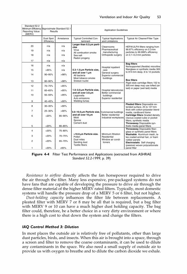
Elsevier UK Ch04-P373998 3-11-2006 7:32a.m. Page:53 Trimsize:6.5×9.5inches
Basal Font:Palatino Margins:Top:40pt Gutter:55pt Font Size:10/11 Text Width:29pc Depth:51 Lines
Ventilation and Indoor Air Quality 53
Standard 52.2 Minimum EfficiencyReporting Value
(MERV)
Approximate Standard 52.1 Results Application Guidelines
Dust Spot Efficiency
Arrestance Typical Controlled Con-taminant
Typical Applications and Limitations
Typical Air Cleaner/Filter Type
20 n/a n/a
19 n/a n/a
18 n/a n/a
17 n/a n/a
Larger than 0.3 µ m parti-clesVirus All combustion smoke Sea salt Radon progeny
Cleanrooms Pharmaceutical manufacturing
Orthopedic surgery
HEPA/ULPA filters ranging from 99.97% efficiency on 0.3 mm particles to 99.999% efficiency on 0.1–0.2 mm particles
16 n\a n/a
15 >95% n/a
14 90–95% >98%
13 80–90% >98%
0.3–1.0 µm Particle size, and all over 1 µmAll bacteriaMost tobacco smoke Sneeze nuclei
Hospital inpatient care
General surgery Superior commercial buildings
12 70–75% >95%
11 60–65% >95%
10 50–55% >95%
9 40–45% >90%
1.0–3.0 µm Particle size, and all over 3.0 µmLegionellaAuto emissions Welding fumes
Hospital laboratories Better commercial buildings
Superior residential
Bag filters Nonsupported (flexible) microfine fiberglass or synthetic media 305 to 914 mm deep, 6 to 12 pockets
Box filtersRigid style cartridge filters 152 to 305 mm deep may use lofted (air laid) or paper (wet laid) media
8 30–35% >90%
7 25–30% >90%
6 <20% 85–90%
5 <20% 80–85%
3.0–10.0 µm Particle size, and all over 10 µm Mold SporesCement dust
Commercial buildingsBetter residential Industrial workplaces
Pleated filters Disposable ex-tended surface, 25 to 127 mm thick with cotton-polyester blend media, cardboard frame Cartridge filters Graded density viscous coated cube or pocket filters, synthetic media Throwaway Disposable syn-thetic media panel filters
4 <20% 75–80%
3 <20% 70–75%
2 <20% 65–70%
1 <20% <65%
>10.0 µm Particle size.PollenDust mites Sanding dust Textile fibers
Minimum filtration Residential Window air condi-tioners
Throwaway Disposable fiber-glass or synthetic panel filters Washable Aluminum mesh, la-tex coated animal hair, or foam rubber panels Electrostatic Self charging (passive) woven polycarbonate panel filter
Figure 4-4 Filter Test Performance and Applications (extracted from ASHRAEStandard 52.2-1999, p. 39)
Resistance to airflow directly affects the fan horsepower required to drivethe air through the filter. Many less expensive, pre-packaged systems do nothave fans that are capable of developing the pressure to drive air through thedense filter material of the higher MERV rated filters. Typically, most domesticsystems will handle the pressure drop of a MERV 5 or 6 filter, but not higher.
Dust-holding capacity influences the filter life between replacements. Apleated filter with MERV 7 or 8 may be all that is required, but a bag filterwith MERV 9 or 10 can have a much higher dust holding capacity. The bagfilter could, therefore, be a better choice in a very dirty environment or wherethere is a high cost to shut down the system and change the filters.
IAQ Control Method 3: Dilution
In most places the outside air is relatively free of pollutants, other than largedust particles, birds, and insects. When this air is brought into a space, througha screen and filter to remove the coarse contaminants, it can be used to diluteany contaminants in the space. We also need a small supply of outside air toprovide us with oxygen to breathe and to dilute the carbon dioxide we exhale.

Elsevier UK Ch04-P373998 3-11-2006 7:32a.m. Page:54 Trimsize:6.5×9.5inches
Basal Font:Palatino Margins:Top:40pt Gutter:55pt Font Size:10/11 Text Width:29pc Depth:51 Lines
54 Fundamentals of HVAC
Dilution ventilation is the standard method of controlling general pollutantsin buildings and the methods and quantities required are detailed in Standard62.1-2004, which is the subject of the next section.
4.5 ASHRAE Standard 62, Ventilation for AcceptableIndoor Air Quality
ANSI/ASHRAE Standard 62, Ventilation for Acceptable Indoor Air Quality1 waspublished in 1971, 1981, and again fully revised in 1989. The complete revi-sions made it easy to reference in Building Codes. Designers could refer tothe edition stipulated, and there was no question about the reference. Thepolicy was changed for this standard in 1997, to align with the ANSI “contin-uous maintenance” process. Under continuous maintenance, the Standard isupdated a bit at a time and is not required to be a consistent, whole document.The information in this section is based on the 2004 printed edition.
Standard 62.1-2004 applies to “all indoor or enclosed spaces that people mayoccupy” with the provision that additional requirements may be necessaryfor laboratory, industrial, and other spaces. As noted at the beginning of thischapter in the introduction, residential ventilation is specifically covered inASHRAE Standard 62.2-2004, Ventilation and Acceptable Indoor Air Quality inLow-Rise Residential Buildings. You should also note that many local authoritieshave more demanding and specific requirements for residential ventilationthan the ASHRAE standards. For industrial occupancies, refer to IndustrialVentilation, published by the American Conference of Governmental IndustrialHygienists.
The first section of Standard 62.1-2004 states
“The purpose of this standard is to specify minimum ventilationrates and indoor air quality that will be acceptable to human occu-pants and are intended to minimize the potential for adverse healtheffects.”
Note that this is a minimum standard, that it is aimed at providing “accept-able indoor air quality” which is defined as:
“air in which there are no known contaminants at harmful concen-trations as determined by cognizant authorities and with which asubstantial majority (80% or more) of the people exposed do notexpress dissatisfaction.”
The Standard defines two types of requirements to maintain indoor airquality: requirements to limit contamination; and requirements to provideventilation to dilute and remove contaminants. The requirements to limitcontamination also include several system and building design require-ments to minimize moisture problems that typically lead to mold problemsincluding:
Requirements for filteringSeparation distance between outside air inlets and contaminated exhaustsRules about recirculation of air between zones that have different contami-
nation levels

Elsevier UK Ch04-P373998 3-11-2006 7:32a.m. Page:55 Trimsize:6.5×9.5inches
Basal Font:Palatino Margins:Top:40pt Gutter:55pt Font Size:10/11 Text Width:29pc Depth:51 Lines
Ventilation and Indoor Air Quality 55
Requirements for maintenance and operationRequirements for design and maintenance documentation.
Standard 62.1-2004 requires that “Air from smoking areas shall not be recircu-lated or transferred to no-smoking areas.” Also smoking areas “shall have moreventilation and/or air cleaning than comparable no-smoking areas.” Howeverno specific recommendations are included for smoking areas.
There are two approaches to providing ventilation for the occupants tobreathe and to dilute the inevitable pollutants:
i. “The Indoor Air Quality Procedure” Acceptable air quality is achieved withinthe space by controlling known and specifiable contaminants to acceptablelimits. The application of the Indoor Air Quality Procedure allows the useof particulate and gaseous filters to assist in maintaining acceptable indoorair quality. The complexity of the procedure is beyond this course and willnot be discussed.
ii. “The Ventilation Rate Procedure” Acceptable air quality is achieved by pro-viding ventilation air of the specified quality and quantity.
The Ventilation Rate Procedure is based on providing an adequate supplyof acceptable outdoor air to dilute and remove contaminants in the space toprovide acceptable IAQ. Acceptable outdoor air must have pollution levelswithin national standards.
The basic required outside air for ventilation is based on a rate, L/s, perperson, plus a rate per square meter, L/s · m2. This basic requirement is thenadjusted to allow for the ventilation effectiveness in each space and the effec-tiveness of the system. Let us briefly go through those steps. An excerpt ofthe base ventilation data from Table 6-1 in Standard 62.1-2004 is shown inFigure 4-5.
Look at the first occupancy category, the hotel bedroom. The requirementhere is for 2�5 L/s· person per person and 0�3 L/s · m2. Based on the defaultoccupancy density of 10 persons per 100 m2 the combined outdoor rate per100 m2 is
10 people ·2�5 L/s ·person +100 m2 ·0�3 L/s ·m2 = 25 L/s+30 L/s = 55 L/s
The default combined outdoor air rate is thus 55 L/s for 10 people occupying100 m2. Divided by the default population of 10 persons we get 5.5 L/s for thebase requirement per person.
Now look at the last hotel category, multi-purpose assembly. The rate perperson, 2.5 L/s, and rate per m2, 0.3 L/s, are the same. What is different isthe default occupancy density of 120 persons/100 m2. With the much higheroccupancy density the ventilation for the space is much less significant andtherefore the combined outdoor air rate per person is halved to 2.75 L/s, shownrounded up to 2.8 L/s in the table.
These default outdoor air rates must then be adjusted to allow for theproportion of ventilation air that actually circulates through the breathing zone.If we suppose that only 90% of the outdoor air enters the breathing zone, andthe other 10% circulates above the breathing zone and is exhausted, then onlythe 90% of outside air is being used effectively. Therefore, the proportion of airthat actually circulates into the breathing zone is called zone air distributioneffectiveness. In the example, the zone air distribution effectiveness would be

Elsevier UK Ch04-P373998 3-11-2006 7:32a.m. Page:56 Trimsize:6.5×9.5inches
Basal Font:Palatino Margins:Top:40pt Gutter:55pt Font Size:10/11 Text Width:29pc Depth:51 Lines
56 Fundamentals of HVAC
Figure 4-5 Parts of Table 6-1, ASHRAE Standard 62.1-2004
0.9. The breathing zone is defined as between 75 and 1800 mm from the floorand 600 mm from walls or air-conditioning equipment.
Let us consider a space with the ventilation air being provided from a ceilingoutlet. Standard 62.1-2004 gives the zone air distribution effectiveness for coolair supplied at ceiling level as “1.” To obtain the corrected ventilation rate,we divide the base rate by the zone air distribution effectiveness. In this case,default outdoor air rate divided by a zone air distribution effectiveness of “1”means the default rate is unchanged.
Now let us suppose that the same system is used for heating in the winter.In this example, the maximum design supply temperature is 35 �C and spacedesign temperature is 22 �C. The supply air temperature is
35 �C−22 �C = 13 �C
above the temperature of the space. According to Standard 62.1-2004, “Forwarm air over 8 �C above space temperature supplied at ceiling level and ceil-ing return, the zone air distribution effectiveness is 0.8.” In this example, withthe default rate divided by 0.8, we obtain the corrected required ventilation,1/0�8 = 1�25. This means that the outside air requirement has increased by 25%,compared to the cooling-only situation. If this system runs all year, then theventilation should be designed for the higher winter requirement.

Elsevier UK Ch04-P373998 3-11-2006 7:32a.m. Page:57 Trimsize:6.5×9.5inches
Basal Font:Palatino Margins:Top:40pt Gutter:55pt Font Size:10/11 Text Width:29pc Depth:51 Lines
Ventilation and Indoor Air Quality 57
Thus far, we have used the Standard’s Table 6-1 (see Figure 4-5) rates toobtain base ventilation rates and then corrected those to recognize zone airdistribution effectiveness within the space. Now we must consider the effec-tiveness of the system.
If the system supplies just one zone or 100% outside air to several zones,the calculated rate is used. However, if the system serves multiple zones witha mixture of outside air and recirculated return air, we may have to make asystem adjustment to allow for differing proportions of outside air going todifferent zones.
For example, an office building might require 15% outside air to the offices,but 25% to the one conference room. If the system provides only 15%, thenthe conference room will be under-ventilated. However, 25% for the con-ference room will provide much more than the required ventilation to therest of the offices. Standard 62.1-2004 includes a simple calculation to obtaina rate between 15% and 25% that provides adequate outside air for all thezones.
Further adjustments can be made to allow for variable occupancy and forshort interruptions in system operation. Just one example of this type of adjust-ment can occur in churches with high ceilings. If the services are of limitedduration, say under an hour and a half, and the volume of the zone is large perperson, then the outside air ventilation rate can be based on an average pop-ulation over a calculated period. This may substantially reduce the requiredflow of outside air.
This discussion has all been based on Standard 62.1-2004. In many jurisdic-tions, earlier versions of the standard will remain the legal requirement formany years. If this is the case in your jurisdiction, it is important to know thatprevious versions of the Standard generally calculated the required ventilationbased on L/s-per-person and took no separate account of the size of the zone.The simpler requirement facilitated a simple method of adjusting ventilationrates to meet actual occupancy needs in densely occupied spaces. The follow-ing section describes how carbon dioxide can be used to determine ventilationrequirements in these situations.
The Use of Carbon Dioxide to Control Ventilation Rate
All versions of the Standard allow for reduced ventilation when the populationdensity is known to be lower. For example, the ventilation for a movie theatremust be sized for full occupancy, although the theatre may often be less thanhalf-full. In these “less-than-full” times it would save energy if we could reducethe ventilation rate to match the actual population. In the versions of Standard62 that preceded 2004, the ventilation rates were based on L/s per person.As a result, the ventilation could be adjusted based on the number of peoplepresent.
Conveniently for the purposes of measurement, people inhale air that con-tains oxygen and exhale a little less oxygen and some carbon dioxide. Theamount of carbon dioxide, CO2, that is exhaled is proportional to a person’sactivity: more CO2 is exhaled the more active the person. This exhaled CO2can be measured and used to assess the number of people present.
In our movie theatre, the people (assume adults) are all seated and themetabolic rate is about 1.2 met. At 1.2 met, the average CO2 exhaled by adultsis 0.0052 L/s. At the same time as the people are exhaling CO2, the ventilationair is bringing in outside air with a low level of CO2, as indicated in Figure 4-6.
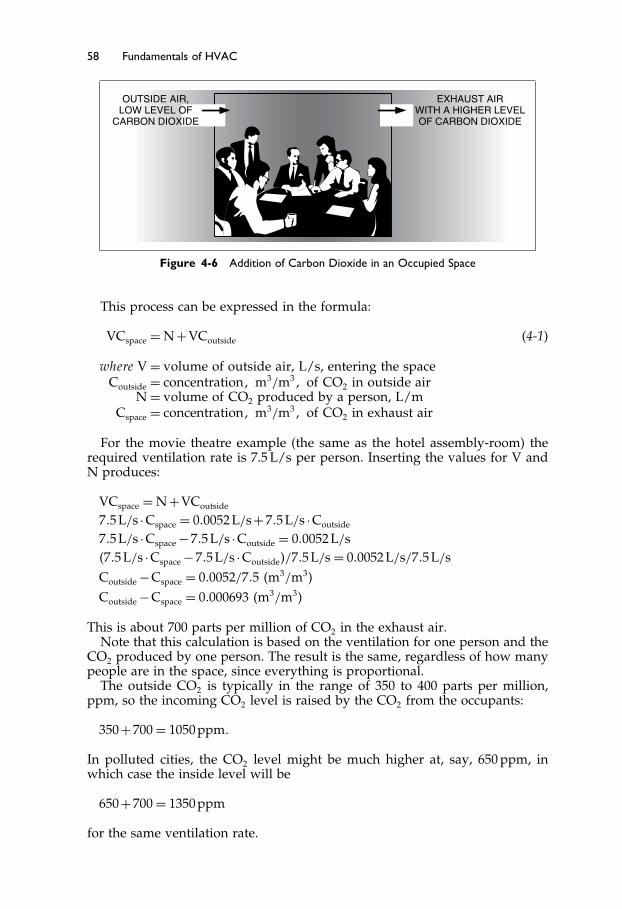
Elsevier UK Ch04-P373998 3-11-2006 7:32a.m. Page:58 Trimsize:6.5×9.5inches
Basal Font:Palatino Margins:Top:40pt Gutter:55pt Font Size:10/11 Text Width:29pc Depth:51 Lines
58 Fundamentals of HVAC
EXHAUST AIRWITH A HIGHER LEVELOF CARBON DIOXIDE
OUTSIDE AIR,LOW LEVEL OF
CARBON DIOXIDE
Figure 4-6 Addition of Carbon Dioxide in an Occupied Space
This process can be expressed in the formula:
VCspace = N +VCoutside (4-1)
where V = volume of outside air, L/s, entering the spaceCoutside = concentration� m3/m3� of CO2 in outside air
N = volume of CO2 produced by a person, L/mCspace = concentration� m3/m3� of CO2 in exhaust air
For the movie theatre example (the same as the hotel assembly-room) therequired ventilation rate is 7.5 L/s per person. Inserting the values for V andN produces:
VCspace = N +VCoutside
7�5 L/s ·Cspace = 0�0052 L/s+7�5 L/s ·Coutside
7�5 L/s ·Cspace −7�5 L/s ·Coutside = 0�0052 L/s�7�5 L/s ·Cspace −7�5 L/s ·Coutside�/7�5 L/s = 0�0052 L/s/7�5 L/sCoutside −Cspace = 0�0052/7�5 �m3/m3�
Coutside −Cspace = 0�000693 �m3/m3�
This is about 700 parts per million of CO2 in the exhaust air.Note that this calculation is based on the ventilation for one person and the
CO2 produced by one person. The result is the same, regardless of how manypeople are in the space, since everything is proportional.
The outside CO2 is typically in the range of 350 to 400 parts per million,ppm, so the incoming CO2 level is raised by the CO2 from the occupants:
350+700 = 1050 ppm�
In polluted cities, the CO2 level might be much higher at, say, 650 ppm, inwhich case the inside level will be
650+700 = 1350 ppm
for the same ventilation rate.

Elsevier UK Ch04-P373998 3-11-2006 7:32a.m. Page:59 Trimsize:6.5×9.5inches
Basal Font:Palatino Margins:Top:40pt Gutter:55pt Font Size:10/11 Text Width:29pc Depth:51 Lines
Ventilation and Indoor Air Quality 59
In our theatre, we can install a CO2 sensor to measure the CO2 level, andconnect it to a controller to open the outside air dampers to maintain the CO2level at no higher than 1000 ppm. In this way the outside air provided matchesthe requirements of the people present. If the outside CO2 concentration isabove 300 ppm, then our controller, set at 1000 ppm, will cause over-ventilationrather than under-ventilation.
In this process CO2 is used as a surrogate indicator for the number of peoplepresent.
The use of CO2 control works really well in a densely populated space servedby a dedicated system. It works poorly in a building with a very variable andlow population.
This calculation assumes a perfect world. As we all know, this is a falseassumption. The main assumptions are:
Perfect mixing. Mixing is usually quite good but some ventilation air maynot reach the occupied space.
Steady state. It will take from 15 minutes to several hours for the CO2concentration to become really steady. The length of time depends onthe volume of space per person. In densely populated spaces, steadystate can be reached quite quickly, but in low population density areas,it can take hours.
An even distribution of people in the space. If people are clumped togetherthen the level will be higher in their area and lower in the less denselyoccupied parts of the space.
This simple use of carbon dioxide as a surrogate cannot be used under therequirements of Standard 62.1-2004, due to the L/s · m2 ventilation requirementfor the space. More sophisticated methods are possible for use under therequirements of Standard 62.1-2004, but they are beyond the scope of thiscourse.
The Next Step
Having introduced the ideas of air-conditioning zones in Chapter 2, thermalcomfort in Chapter 3, and indoor air quality and ventilation rates in thischapter, we will go on in Chapter 5 to consider why air conditioning zonesare required, how to choose zones, and how they can be controlled.
Summary
Chapter 4 deals with the reasons for ventilating buildings, how ventilationrates are chosen for specific situations, and the how to determine and maintaingood indoor air quality, IAQ.
4.1 Introduction
The maintenance of good indoor air quality (IAQ) is one of the major objectivesof air-conditioning systems, because IAQ problems are a significant threat tohealth and productivity. The primary factors that influence and degrade IAQare particles, gases, and vapors in the air.

Elsevier UK Ch04-P373998 3-11-2006 7:32a.m. Page:60 Trimsize:6.5×9.5inches
Basal Font:Palatino Margins:Top:40pt Gutter:55pt Font Size:10/11 Text Width:29pc Depth:51 Lines
60 Fundamentals of HVAC
4.2 Air Pollutants and Contaminants
Air pollutants and contaminants are unwanted airborne constituents thatmay reduce the acceptability of air. Some contaminants are brought into theconditioned space from outside, and some are generated within the spaceitself.
4.3 Indoor Air Quality Effects on Health and Comfort
Contaminants can be classified based on their effects: fatal in the short-term,carcinogenic (cancer causing substances), health threatening, and annoying,with an impact on productivity and sense of well-being.
4.4 Controlling Indoor Air Quality
Maintaining acceptable IAQ depends on the judicious use of three meth-ods: source control, filtration, and dilution. This section also included a moredetailed discussion on source control, and on filtration.
4.5 ASHRAE Standard 62, Ventilation for Acceptable Indoor Air Quality
ANSI/ASHRAE Standard 62, Ventilation for Acceptable Indoor Air Quality1 waspublished in 1971, 1981, and again fully revised in 1989. The complete revisionsmade it easy to reference in Building Codes. In many jurisdictions, earlierversions of the standard will remain the legal requirement for many years.
Since 1997, to align with the ANSI “continuous maintenance” process, theStandard is updated a bit at a time and is not required to be a consistent, wholedocument. Standard 62.1-2004 applies to “all indoor or enclosed spaces thatpeople may occupy” with the provision that additional requirements may benecessary for laboratory, industrial, and other spaces.
We introduced the idea of the ventilation rate procedure, and the formula
VCspace = N +VCoutside
Bibliography
1. ASHRAE. 2004. ANSI/ASHRAE Standard 62.1-2004, Ventilation for Acceptable Indoor AirQuality. Atlanta: American Society of Heating, Refrigerating and Air-ConditioningEngineers, Inc.
2. ASHRAE. 2004. ANSI/ASHRAE Standard 62.2-2004, Ventilation and Acceptable IndoorAir Quality in Low-Rise Residential Buildings. Atlanta: American Society of Heating,Refrigerating and Air-Conditioning Engineers, Inc.
3. American Conference of Governmental Industrial Hygienists. 1998. IndustrialVentilation: A Manual of Recommended Practice, 23rd edition. Cincinnati: AmericanConference of Governmental Industrial Hygienists.

Elsevier UK Ch04-P373998 3-11-2006 7:32a.m. Page:61 Trimsize:6.5×9.5inches
Basal Font:Palatino Margins:Top:40pt Gutter:55pt Font Size:10/11 Text Width:29pc Depth:51 Lines
Ventilation and Indoor Air Quality 61
4. ASHRAE. 1992. ASHRAE Standard 52.1-1992, Gravimetric and Dust Spot Proceduresfor Testing Air Cleaning Devices used in General Ventilation for Removing ParticulateMatter. Atlanta: American Society of Heating, Refrigerating and Air-ConditioningEngineers, Inc.
5. ASHRAE. 1999. ASHRAE Standard 52.2-1999, Method for Testing General VentilationAir-Cleaning Devices for the Removal Efficiency by Particle Size. Atlanta: American Soci-ety of Heating, Refrigerating and Air-Conditioning Engineers, Inc.
Elsevier UK Ch05-P373998 3-11-2006 7:32a.m. Page:62 Trimsize:6.5×9.5inches
Basal Font:Palatino Margins:Top:40pt Gutter:55pt Font Size:10/11 Text Width:29pc Depth:51 Lines
Chapter 5
Zones
Contents of Chapter 5
InstructionsObjectives of Chapter 55.1 Introduction5.2 What is a Zone?5.3 Zoning Design5.4 Controlling the ZoneThe Next StepSummary
Instructions
Read the Chapter. Re-read the parts of the chapter that are emphasized in thesummary and memorize important definitions.
Objectives of Chapter 5
We have talked, in a general way, about spaces and zones earlier in Chapter 2,Section 2.4. In this chapter we will go into detail about the reasons for choosingzones, economic considerations, and how zone controls operate. After studyingthe chapter, you should be able to:
Define a space and give examples of spaces.Define a zone and give examples of zones.List a number of reasons for zoning a building and give examples of the
reasons.Make logical choices about where to locate a thermostat.
5.1 Introduction
In Chapter 2, we discussed the fact that spaces have different users and dif-ferent requirements, and in Chapter 4 we discussed issues of thermal comfort.To maximize thermal comfort, systems can be designed to provide indepen-dent control in the different spaces, based on their users and requirements.Each space, or group of spaces, that has an independent control is calleda “zone.”

Elsevier UK Ch05-P373998 3-11-2006 7:32a.m. Page:63 Trimsize:6.5×9.5inches
Basal Font:Palatino Margins:Top:40pt Gutter:55pt Font Size:10/11 Text Width:29pc Depth:51 Lines
Zones 63
In this chapter, we consider what constitutes a zone, the factors that influencezone choices, and the issues concerning location of the zone thermostat.
5.2 What is a Zone?
We have introduced and used the words “space” and “zone” in previouschapters.
To recap, a “space” is a part of a building that is not necessarily separatedby walls and floors. A space can be large, like an aircraft hanger, or small, likea personal office.
A “zone” is a part of a building whose HVAC system is controlled by asingle sensor. The single sensor is usually, but not always, a thermostat. Eitherdirectly or indirectly, a thermostat controls the temperature at its location.
A zone may include several spaces, such as a row of offices whose temper-ature is controlled by one thermostat in one of the offices. On the other handa zone may be a part of a space, such as the area by the window in a largeopen area office.
The zone may be supplied by its own, separate HVAC system, or the zonemay be supplied from a central system that has a separate control for each zone.
Some examples of spaces and zones are shown in Figure 5-1.Having established the meaning of a zone let us now consider the various
reasons for having zones in a building’s HVAC system.
5.3 Zoning Design
There are several types of zones. These zones are differentiated based on whatis to be controlled, and the variability of what is to be controlled. The mostcommon control parameters are: thermal (temperature), humidity, ventilation,operating periods, freeze protection, pressure, and importance.
The most common reason for needing zones is variation in thermal loads.Consider the simple building floor plan shown in Figure 5-2. Let us assume ithas the following characteristics:
Well-insulatedA multi-story building, identical plan on every floorProvided with significant areas of window for all exterior spacesLow loads due to people and equipment in all spacesLocated in the northern hemisphere.
In this example, we will first consider the perimeter zone requirements onintermediate floors due to changes in thermal loads. These changes can occurbecause of the movement of the sun around the building during the courseof a sunny day. These changes in thermal loads take place because the spacesreceive solar heat from the sun, called solar gain.
The designer’s objective is to use zones to keep all spaces at the setpointtemperature. The setpoint temperature is the temperature that the thermostatis set to maintain.
Early in the morning, the sun rises in the east. It shines on the easterly wallsand through the east windows into spaces NE and SE. Relative to the rest

Elsevier UK Ch05-P373998 3-11-2006 7:32a.m. Page:64 Trimsize:6.5×9.5inches
Basal Font:Palatino Margins:Top:40pt Gutter:55pt Font Size:10/11 Text Width:29pc Depth:51 Lines
64 Fundamentals of HVAC
Space Zones Reason for zones
1. Audience seating The audience area requires cooling and high ventilation when the audience is present. A theatre used
for live performance 2. Stage The stage requires low ventilation and low
cooling until all the lights are turned on, and then high cooling is required.
1. Spectators Spectators need ventilation and warmth.
2. Ice sheet The ice sheet needs low air speeds and low temperature to minimize melting.
Indoor ice rink
3. Space above The space above the spectators and ice may need moisture removal to prevent fogging.
Deep office
1. By the windows People by the window may be affected by the heat load from the sun and by the cool window in winter, external factors.
2. Interior area The interior zone load will change due to the occupants, lights, and any equipment –a cooling load all year.
1. Within 1.8 meters
of the floor The occupied zone is within 1.8 meters ofthe floor and needs to be comfortably warm or cool for congregation. Large church
or mosque 2. Above 1.8 meters The space above does not need to be
conditioned for the congregation.
1. Lobby
2. Security
3. Retail outlets Airport
4. Check-in
This is a huge space with a variety of uses, and extremely variable occupancy and loads.Each zone requires its own conditions.
Figure 5-1 Examples of Spaces and Zones
of the building, these spaces, NE and SE, need more cooling to stay at thesetpoint temperature.
As the morning progresses toward midday, the sun moves around to thesouth so that the SE, S, and SW spaces receive solar gain. However, the solarheat load for the NE space has dropped, since the sun has moved around thebuilding.
As the afternoon progresses, the sun moves around to the west to providesolar gain to spaces SW and NW.
Zoning Design Considerations
While most of the spaces have been experiencing a period of solar gain, thetwo N spaces have had no direct solar gain. Thus, the load in the two N spacesis only dependent on the outside temperature and internal loads, like lights.
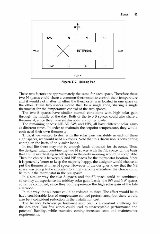
Elsevier UK Ch05-P373998 3-11-2006 7:32a.m. Page:65 Trimsize:6.5×9.5inches
Basal Font:Palatino Margins:Top:40pt Gutter:55pt Font Size:10/11 Text Width:29pc Depth:51 Lines
Zones 65
Figure 5-2 Building Plan
These two factors are approximately the same for each space. Therefore thesetwo N spaces could share a common thermostat to control their temperatureand it would not matter whether the thermostat was located in one space orthe other. These two spaces would then be a single zone, sharing a singlethermostat for the temperature control of the two spaces.
The two S spaces have similar thermal conditions with high solar gainthrough the middle of the day. Both of the two S spaces could also share athermostat, since they have similar solar and other loads.
The remaining spaces: NE, SE, SW, and NW, all have different solar gainsat different times. In order to maintain the setpoint temperature, they wouldeach need their own thermostat.
Thus, if we wanted to deal with the solar gain variability in each of theseeight spaces, we would need six zones. Note that this discussion is consideringzoning on the basis of only solar loads.
In real life there may not be enough funds allocated for six zones. Thus,the designer might combine the two N spaces with the NE space; on the basisthat a little overheating in NE space in the early morning would be acceptable.Then the choice is between N and NE spaces for the thermostat location. Sinceit is generally better to keep the majority happy, the designer would choose toput the thermostat in an N space. However, if the designer knew that the NEspace was going to be allocated to a high-ranking executive, the choice couldbe to put the thermostat in the NE space!
In a similar way the two S spaces and the SE space could be combined,since they all experience the midday solar gain. Lastly, the SW and NW spacescould be combined, since they both experience the high solar gain of the lateafternoon.
In this way, the six zones could be reduced to three. The effect would be tohave considerable loss of temperature control performance, but there wouldalso be a coincident reduction in the installation cost.
The balance between performance and cost is a constant challenge forthe designer. Too few zones could lead to unacceptable performance andpotential liability, while excessive zoning increases costs and maintenancerequirements.

Elsevier UK Ch05-P373998 3-11-2006 7:32a.m. Page:66 Trimsize:6.5×9.5inches
Basal Font:Palatino Margins:Top:40pt Gutter:55pt Font Size:10/11 Text Width:29pc Depth:51 Lines
66 Fundamentals of HVAC
Interior and Roof Zones
The discussion so far has ignored both the internal zone and the effect of theroof. The internal zones on intermediate floors are surrounded by conditionedspaces. As a result, they never need heating, are not affected by solar gain andneed cooling when occupied all year. In a cool climate this can often create asituation where all exterior zones require heating but the interior zones stillrequire cooling. The different behavior of interior zones can be dealt with byputting them on a separate system.
The top floor perimeter zones are also different from the intermediate floorzones since they have the added summer roof solar gain and the winter heatloss. On the top floor, interior zones are also affected by solar gain and winterheat loss. As a result the top floor design needs special consideration withadditional cooling and heating abilities.
Choosing zones is always a cost/benefit trade-off issue. In an ideal world,every occupant would have control of their own part of the space. In practicethe cost is generally not warranted. As a result the designer has to go througha selection process, like we did in this example, to decide which spaces in abuilding can be combined. In our example, we only considered solar gain, butin a real building the designer must consider all relevant factors. Commonfactors are outlined below:
Thermal Variation
Solar gain. As shown in the example, solar gain through windows can create asignificant difference in cooling load, or the need for heating, at varying timesof the day according to window orientation.
Wall or roof heat gains or heat losses. The spaces under the roof in a multi-floorbuilding will experience more heat gain in summer, or heat loss in winter,than spaces on the lower floors.
Occupancy. The use of spaces and the importance of maintaining good tem-perature control will influence how critical zoning is.
Equipment and associated heat loads. Equipment that gives off significant heatmay require a separate zone in order to maintain a reasonable temperature forthe occupants. For example, a row of private offices may have worked wellas a single zone, but the addition of a personal computer and a server in oneof those offices would make it very warm compared to the other offices. Thisoffice could require separate zone design.
Freeze protection in cold climates. In a cold climate, the perimeter walls androof lose heat to the outside. Therefore, it is often advantageous to designatethe perimeter spaces as separate heating zones from those in the core of thebuilding.
Ventilation with Outside Air
Occupancy by people. In a typical office building, the population density is rela-tively low. However, conference rooms have a fairly high potential populationdensity, and therefore a variable ventilation load. As a result, conference roomsare often treated as different zones for ventilation and for time of operation,compared to the offices in a building.
Exhausts from washrooms. As noted in Chapter 4, washrooms may be treatedas a separate zone and provided only with exhaust. The exhausted air may bemade up of air from the surrounding spaces.

Elsevier UK Ch05-P373998 3-11-2006 7:32a.m. Page:67 Trimsize:6.5×9.5inches
Basal Font:Palatino Margins:Top:40pt Gutter:55pt Font Size:10/11 Text Width:29pc Depth:51 Lines
Zones 67
Exhausts from equipment and fume hoods. Often, equipment is required to oper-ate continuously, although the majority of the building is only occupied duringworking hours, Monday to Friday. In these cases, it may be advantageous totreat spaces with continuous exhaust as a separate zone or even service themfrom a separate system.
Time of Operation
Timed. In many buildings, the time of operation of spaces differs. For example,an office building might have several floors occupied by tenants who are happywith full service only during working hours from Monday to Friday. Onefloor could be occupied by a weather forecasting organization that requiresfull operation 24 hours a day, seven days a week. In this case it might beadvantageous to have the building zoned to only provide service when andwhere needed.
On demand – manual control or manual start for timed run. In many buildingsthere are spaces that are only used on occasion. They may be designed asseparate zones, which are switched on when needed. The activation can be bymeans of an occupancy sensor, or by a manual start switch in the space, whichruns the zone for a predetermined time. For example a low-use lecture theatrein a university building might be provided with a push button start that wouldenergize the controls to run the space air conditioning for two hours beforeswitching off.
Humidity
Mold protection in hot, humid climates. In hot, humid climates, the moisturecan infiltrate into the building through leaks in the walls, doors, and win-dows. This can cause the building contents to mold unless dehumidification isactivated.
Humidity sensors can be installed in individual representative zones thatwill measure relative humidity. If these sensors detect excess humidity in thesezones, they can trigger the system to provide system-wide dehumidification.The control system can be designed to provide dehumidification without ven-tilation during unoccupied hours.
Museum and art gallery requirements for good humidity control. High qualitymuseums and art galleries have to maintain accurate control of the humid-ity in the storage and exhibit areas. This humidity control is generally notrequired in other spaces like offices, restaurants, merchandising, and lobbyareas. Therefore museums and art galleries often have at least two systems, toprovide the collections with the required humidity control.
Pressure
Air flows from places at a higher pressure to places at a lower pressure.A difference in pressure can be used to control the movement of airborne
contaminants in the building. For example, in a hospital, the tuberculosis (TB)patient rooms can be kept at a negative pressure compared to surroundingareas, to ensure that no TB germs, known as bacilli, migrate into surround-ing areas.
In a similar way, kitchens, smoking rooms, and toilets are kept negativeto contain the odors by exhausting more air than is supplied to the spaces.Conversely, a photographic processing laboratory is kept at a positive pressureto minimize the entry of dust.

Elsevier UK Ch05-P373998 3-11-2006 7:32a.m. Page:68 Trimsize:6.5×9.5inches
Basal Font:Palatino Margins:Top:40pt Gutter:55pt Font Size:10/11 Text Width:29pc Depth:51 Lines
68 Fundamentals of HVAC
Zoning Problems
One recurring problem with zoning is change in building use after the designhas been completed. If there are likely to be significant changes in layout oruse, then the designer should choose a system and select zones that will makezone modification as economical and easy as practical.
Having reviewed the reasons for choosing to zone a building, let’s considerthe control of the zone.
5.4 Controlling the Zone
The most common zone control device is the thermostat. It should be placedwhere it is most representative of the occupants’ thermal experience. A ther-mostat is usually mounted on the wall. It is designed to keep a constanttemperature where it is, but it has no intelligence; it does not know what isgoing on around it. The following are some of the issues to be aware of whenchoosing the thermostat location.
• Mounting the thermostat in a location where the sun can shine on it willcause it to overcool the zone when the sun shines on it. The sun providesconsiderable radiant heat to the thermostat. The thermostat interprets theradiant heat as though the whole location had grown too warm, and itwill signal the air conditioning system that it requires a lower air temper-ature. As a result, the occupants will be cold, and cooling expenses willescalate.
• In many hotels, the thermostat is mounted by the door to the meeting room. Ifthe door is left open, a cold or warm draft from the corridor can significantly,and randomly, influence the thermostat.
• In some conference or assembly rooms, the thermostat is mounted abovelighting dimmer switches. These switches produce heat that rises up intothe thermostat, signaling that the room is warmer than it actually is. If thedimmers are left alone and their output is constant, the thermostat can be setat a setpoint that allows for the heating from the dimmers. Unfortunately thedimmers heat output changes if the dimmer setting is adjusted, so adjustingthe lighting level will alter the thermostat performance.
• Mounting a thermostat on an outside wall can also cause problems. If the wallbecomes warm due to the sun shining on it, the thermostat will lower the airtemperature to compensate. This offsets the increased radiant temperatureof the wall on the occupants, but usually the effect is far too much and theroom becomes cool for the occupants. In a similar way, in the winter the wallbecomes cool and a cool draft will move down the wall over the thermostat,causing it to raise the air temperature to compensate.
• There are times when heat from equipment can offset the thermostat. Acomputer mounted on a desk under a thermostat can easily generate enoughheat to cause the thermostat to lower the air temperature. If the computer isonly turned on periodically, perhaps to drive a printer, this offset will occurat apparently random times, creating a difficult problem for the maintenancestaff to resolve.
• If the thermostat is mounted where it is directly affected by the heating orthe cooling of the space, it will likely not maintain comfortable conditions.For example, suppose that the air-conditioning system’s air supply blows

Elsevier UK Ch05-P373998 3-11-2006 7:32a.m. Page:69 Trimsize:6.5×9.5inches
Basal Font:Palatino Margins:Top:40pt Gutter:55pt Font Size:10/11 Text Width:29pc Depth:51 Lines
Zones 69
directly onto the thermostat. In the heating mode, the thermostat will warmup quickly when the hot air stream blows over it. Therefore, it will quicklydetermine that the room is warm enough and turn off the heat. The resultwill be rapid cycling of the thermostat and the room will be kept coolerthan the setpoint temperature. Conversely, when in the cooling mode, thethermostat will be quickly cooled and will cycle rapidly, keeping the roomwarmer than the setpoint temperature.
If the system has been adjusted to work satisfactorily during the heatingseason, then when the system changes over to cooling, the thermostat willkeep the zone warmer than it did when in the heating mode. Complaintswill result and the thermostat will get adjusted to satisfactory operationin the cooling mode. When the season changes, the shift will reverse andreadjustment will be required once more. This is the sort of regular seasonalproblem that occurs in many air-conditioning systems.
• Wall-mounted thermostats generally have a cable connecting them to therest of the control system. The hole, tubing, or conduit can allow air froman adjoining space or the ceiling to blow into the thermostat, giving it afalse signal.
• Lastly, mounting a thermostat near an opening window can also cause ran-dom air temperature variations as outside air blows, or does not blow, overthe thermostat.
Humidity
While this discussion has been all about thermostats and poor temperature con-trol, the issues are very similar for humidity, which is controlled by humidis-tats. The result of failing to consider placement of the humidistat will bepoor humidity control. Remember, as we discussed in Chapter 2, Section 2.2,if the temperature rises, then relative humidity drops and conversely, if thetemperature falls then the humidity rises.
The Next Step
Having considered the issues around zones, we are now going to considertypical systems that provide zone control. In Chapter 6 we will be consideringsingle zone systems and in Chapter 7, systems with many zones.
Summary
5.2 What is a Zone?
A zone is a section of a building where the HVAC system is controlled by asingle sensor. The single sensor is usually, but not always, a thermostat. Eitherdirectly or indirectly, a thermostat controls the temperature at its location.
5.3 Zoning Design
Zones are chosen based on what is to be controlled and the variability of whatis to be controlled. The most common control parameters include temperature,
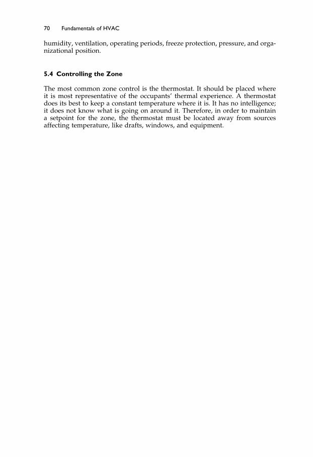
Elsevier UK Ch05-P373998 3-11-2006 7:32a.m. Page:70 Trimsize:6.5×9.5inches
Basal Font:Palatino Margins:Top:40pt Gutter:55pt Font Size:10/11 Text Width:29pc Depth:51 Lines
70 Fundamentals of HVAC
humidity, ventilation, operating periods, freeze protection, pressure, and orga-nizational position.
5.4 Controlling the Zone
The most common zone control is the thermostat. It should be placed whereit is most representative of the occupants’ thermal experience. A thermostatdoes its best to keep a constant temperature where it is. It has no intelligence;it does not know what is going on around it. Therefore, in order to maintaina setpoint for the zone, the thermostat must be located away from sourcesaffecting temperature, like drafts, windows, and equipment.

Elsevier UK Ch06-P373998 3-11-2006 7:33a.m. Page:71 Trimsize:6.5×9.5inches
Basal Font:Palatino Margins:Top:40pt Gutter:55pt Font Size:10/11 Text Width:29pc Depth:51 Lines
Chapter 6
Single Zone Air Handlers andUnitary Equipment
Contents of Chapter 6
InstructionsObjectives of Chapter 66.1 Introduction6.2 Examples of Buildings with Single-Zone Package
Air-Conditioning Units6.3 Air-Handling Unit Components6.4 The Refrigeration Cycle6.5 System Performance Requirements6.6 Rooftop Units6.7 Split SystemsThe Next StepSummaryBibliography
Instructions
Read the material in the chapter. Re-read the parts of the chapter emphasizedin the summary.
Objectives of Chapter 6
After studying Chapter 6, you will be able to:
Identify the main components of a single zone air handler and describe theiroperation.
Describe the parameters that have to be known to choose an air-conditioningair-handling unit.
Describe how the vapor compression refrigeration cycle works.Identify the significant issues in choosing a single-zone rooftop air-
conditioning unit.Understand the virtues of a split system.

Elsevier UK Ch06-P373998 3-11-2006 7:33a.m. Page:72 Trimsize:6.5×9.5inches
Basal Font:Palatino Margins:Top:40pt Gutter:55pt Font Size:10/11 Text Width:29pc Depth:51 Lines
72 Fundamentals of HVAC
6.1 Introduction
In the previous chapters we have discussed ventilation for maintaining indoorair quality, the thermal requirements for comfort, and reasons for zoninga building. In this chapter we are going to consider packaged single-zoneair-conditioning equipment, examine issues of system choice, and provide ageneral description of system control issues. We will return to controls in moredepth in Chapter 11.
The single-zone air-conditioning equipment we will be discussing is thepiece of equipment that was introduced in Chapter 2, Figure 2-12. This unit istypically referred to as the single zone air handler, or air-handling unit, oftenabbreviated to AHU. In this chapter, we will refer to it as the air handler orthe unit. The air handler draws in and mixes outside air with air that is beingrecirculated, or returned from the building, called return air. Once the outsideair and the return air are mixed, the unit conditions the mixed air, blows theconditioned air into the space, and exhausts any excess air to outside, usingthe return-air fan.
Before getting into a discussion of the components of a single-zone packageair-conditioning unit, we need some context as to where it fits into the wholebuilding or site systems.
6.2 Examples of Buildings with Single-Zone PackageAir-Conditioning Units
Figure 6-1 shows four identical single-story buildings, A, B, C, and D. Eachhas a single-zone package air-conditioning unit (marked “AHU”) located onthe roof.
Building A: This unit has only an electrical supply. This single electricalsupply provides all the power for heating, cooling, humidifying, andfor driving the fans.
Building B: This unit has the electrical supply for cooling, humidifying, andfor driving the fans, while the gas line, shown as “gas supply,” providesheating.
These first two arrangements are commonly available as factory engineered,off the shelf, rooftop packages. Among these packaged units, there is a greatrange in size, quality, and features. The most basic provide few, if any, options.They are relatively difficult to service and have a relatively short life. At theother end of the spectrum, there are large units with walk-in service accessand numerous energy-conserving options. These are designed to last as longas any indoor equipment.
As well as the total pre-packaged units, there are units, typically in largerbuildings or complexes of buildings, where the heating is provided from acentral service. For example, a boiler room can produce hot water that is pipedaround the building or buildings to provide heat. Each air-handling unit thatneeds heating has hot water piped to it.
Building C: This unit has the electrical supply for cooling, humidifying,and for driving the fans. It also has supply and return hot-water pipes
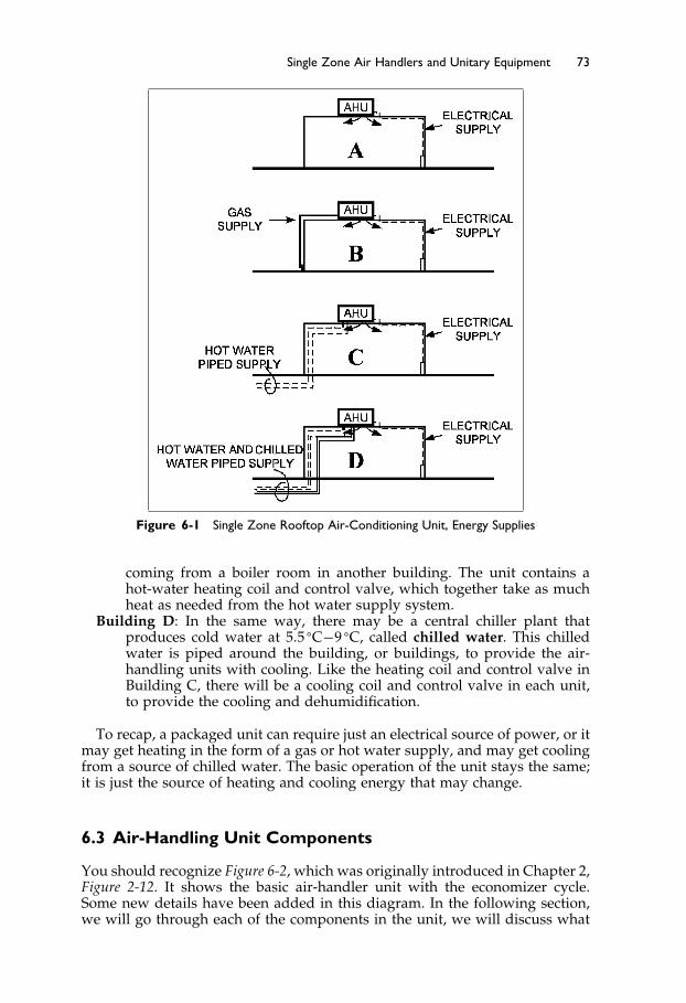
Elsevier UK Ch06-P373998 3-11-2006 7:33a.m. Page:73 Trimsize:6.5×9.5inches
Basal Font:Palatino Margins:Top:40pt Gutter:55pt Font Size:10/11 Text Width:29pc Depth:51 Lines
Single Zone Air Handlers and Unitary Equipment 73
Figure 6-1 Single Zone Rooftop Air-Conditioning Unit, Energy Supplies
coming from a boiler room in another building. The unit contains ahot-water heating coil and control valve, which together take as muchheat as needed from the hot water supply system.
Building D: In the same way, there may be a central chiller plant thatproduces cold water at 5�5 �C−9 �C, called chilled water. This chilledwater is piped around the building, or buildings, to provide the air-handling units with cooling. Like the heating coil and control valve inBuilding C, there will be a cooling coil and control valve in each unit,to provide the cooling and dehumidification.
To recap, a packaged unit can require just an electrical source of power, or itmay get heating in the form of a gas or hot water supply, and may get coolingfrom a source of chilled water. The basic operation of the unit stays the same;it is just the source of heating and cooling energy that may change.
6.3 Air-Handling Unit Components
You should recognize Figure 6-2, which was originally introduced in Chapter 2,Figure 2-12. It shows the basic air-handler unit with the economizer cycle.Some new details have been added in this diagram. In the following section,we will go through each of the components in the unit, we will discuss what

Elsevier UK Ch06-P373998 3-11-2006 7:33a.m. Page:74 Trimsize:6.5×9.5inches
Basal Font:Palatino Margins:Top:40pt Gutter:55pt Font Size:10/11 Text Width:29pc Depth:51 Lines
74 Fundamentals of HVAC
Figure 6-2 Air-Conditioning System: Single-Zone Air Handler
each component does, and, in general terms, how each component can becontrolled. This unit is typically referred to as the single-zone air handler.
The overall functions of the air-handler are to draw in outside air and returnair, mix them, condition the mixed air, blow the conditioned air into the space,and exhaust any excess air to outside.
Air inlet and mixing section
The inlet louver and screen restrict entry into the system. The inlet louver isdesigned to minimize the entry of rain and snow. A very simple design forthe inlet louver is shown in the diagram. Maintaining slow air-speed throughthe louver avoids drawing rain into the system. More sophisticated, and morecostly designs allow higher inlet-velocities without bringing in the rain. Thescreen is usually a robust galvanized-iron mesh, which restricts entry of ani-mals, birds, insects, leaves, etc.
Once the outside air has been drawn in, it is mixed with return air. InFigure 6-2, a parallel blade damper
/ / / / / /
is shown for both the outside air damper and the relief air damper.These dampers direct the air streams toward each other, causing turbulence
and mixing. Mixing the air streams is extremely important in very cold cli-mates, since the outside air could freeze coils that contain water as the heating

Elsevier UK Ch06-P373998 3-11-2006 7:33a.m. Page:75 Trimsize:6.5×9.5inches
Basal Font:Palatino Margins:Top:40pt Gutter:55pt Font Size:10/11 Text Width:29pc Depth:51 Lines
Single Zone Air Handlers and Unitary Equipment 75
medium. A special mixing section is installed in some systems where there isvery little space for the mixing to naturally occur.
It is also possible to install opposed blade dampers:
/ \ / \ / \
These do a better job of accurately controlling the flow, but a somewhat poorerjob of promoting mixing.
Some air will be exhausted directly to the outside from washrooms and otherspecific sources, like kitchens. The remainder will be drawn back through thereturn air duct by the return air fan and either used as return air, or exhaustedto outside through the relief air damper. This exhausted air is called the reliefair. The relief air plus the washroom exhaust and other specific exhaust air willapproximately equal the outside air that is brought in. Thus, as the incomingoutside air increases, so does the relief air. It is common, therefore, to linkthe outside-air damper, the return-air damper, and the relief-air dampers anduse a single device, called an actuator, to move the dampers in unison. Whenthe system is “off,” the outside-air and relief-air dampers are fully closed, andthe return-air damper is fully open. The system can be started and all the airwill recirculate through the return damper. As the damper actuator drives thethree dampers, the outside-air and relief-air dampers open in unison as thereturn-air damper closes.
Mixed Temperature Sensor
Generally, the control system needs to know the temperature of the mixed airfor temperature control. A mixed-temperature sensor can be strung across theair stream to obtain an average temperature. If mixing is poor, then the averagetemperature will be incorrect. To maximize mixing before the temperature ismeasured, the mixed temperature sensor is usually installed downstream ofthe filter.
When the plant starts up, the return air flows through the return damper andover the mixed temperature sensor. Because there is no outside air in the flow,the mixed-air temperature is equal to the return-air temperature. The dampersopen, and outside air is brought into the system, upstream of the mixed-airsensor. If the outside temperature is higher than the return temperature, asthe proportion of outside air is increased, the mixed-air temperature will rise.Conversely, if it is cold outside, as the proportion of outside air is increased,the mixed-air temperature will drop. In this situation, it is common to set thecontrol system to provide a mixed-air temperature somewhere between 13 and16 �C. The control system can simply adjust the position of the dampers tomaintain the set mixed temperature.
For example, consider a system with a required mixed temperature of 13 �Cand return temperature of 23 �C. When the outside temperature is 13 �C, 100%outside air will provide the required 13 �C. When the outside air tempera-ture is below 13 �C, the required mixed temperature of 13 �C can be achievedby mixing outside air and return air. As the outside temperature drops, thepercentage required to maintain 13 �C will decrease. If the return temper-ature is 23 �C, at 3 �C there will be 50% outside air, and at −27 �C, 20%outside air.

Elsevier UK Ch06-P373998 3-11-2006 7:33a.m. Page:76 Trimsize:6.5×9.5inches
Basal Font:Palatino Margins:Top:40pt Gutter:55pt Font Size:10/11 Text Width:29pc Depth:51 Lines
76 Fundamentals of HVAC
If the building’s ventilation requirements are for a minimum of 20% outsideair, then any outside temperature below −27 �C will cause the mixed temper-ature to drop below 13 �C. In this situation, the mixed air will be cooler than13 �C and will have to be heated to maintain 13 �C. The mixed-air temperature-sensor will register a temperature below 13 �C. The heating coil will then turn“on” to provide enough heat to raise the supply-air temperature (as measuredby the supply-temperature sensor) to 13 �C.
Now let us consider what happens when the outside-air temperature risesabove 13 �C. Up to 23 �C, the temperature of the outside air will be lower thanthe return air, so it would seem best to use 100% outside air until the outsidetemperature reaches 23 �C. In practice, this is not always true, because themoisture content of the outside air will influence the decision. In a very dampclimate, the changeover will be set much lower than 23 �C, since the enthalpyof the moist, outside air will be much higher than the dryer return air, at 23 �C.Above the pre-determined changeover temperature, the dampers revert to theminimum ventilation rate, 20% outside air in this example.
The last few paragraphs have discussed how the system is controlled, calledthe control operation. These control operations can be summarized in thefollowing point form, often called the control logic:
• When system off, the outside air and relief air dampers fully closed, returnair dampers fully open.
• When system starts, if outside temperature above −7 �C, adjust dampers toprovide x L/s of outside air.
• When system starts, if outside temperature below −7 �C, modulate dampersto maintain 15 �C mixed temperature with a minimum of x L/s of outside air.
The requirement for a minimum volume of outside air means that the con-troller must have a way of measuring the outside air volume. This can beachieved in a number of ways that are explained in the ASHRAE CourseFundamentals of Air System Design.1
The preceding text has talked about air volumes without getting into specificnumbers. Note that the weight (mass if you leave earth) of outside air enteringthe building must equal the weight of air that leaves the building. The volumeof air that is entering and leaving will usually be different, since the volumeincreases with increasing temperature. For example:
13.4 kg/s, 10000 L/s of outside air, at −10 �C, enters a building.
It is heated, and leaves the building as
13.4 kg/s, 11260 L/s at 23 �C (11% greater volume, same weight)
Filter
All packaged units include as least minimal filters. Often it is beneficial tospecify better filters, as we discussed in Section 4.4.
Heating Coil
Some systems require very high proportions, or even 100% outside air. In mostclimates this will necessitate installing a heating coil to raise the mixed airtemperature. The heat for the heating coil can be provided by electricity, gas,water, or steam.

Elsevier UK Ch06-P373998 3-11-2006 7:33a.m. Page:77 Trimsize:6.5×9.5inches
Basal Font:Palatino Margins:Top:40pt Gutter:55pt Font Size:10/11 Text Width:29pc Depth:51 Lines
Single Zone Air Handlers and Unitary Equipment 77
The electric coil is the simplest choice, but the cost of electricity often makesit an uneconomic one.
A gas-fired heater often has the advantage of lower fuel cost, but controlcan be an issue. Inexpensive gas heaters are “on-off” or “high-low-off” ratherthan fully modulating. As a result, the output temperature has step changes.If the unit runs continuously with the heat turning on and off, then the supplytemperature will go up and down with the heater cycle and occupants mayexperience a draft.
Hot water coils are the most controllable, but there is a possibility that theywill freeze in cold weather. If below-freezing temperatures are common, then itis wise to take precautions against coil freezing. Many designers will, therefore,include a low-temperature alarm and arrange the controls to keep the coilwarm or hot, when the unit is off during cold weather.
This is one of the times when the designer needs to take precautions againstthe consequences of the failure of a component. If, for example, the damperlinkage fails, the unit may be “off,” with the outside dampers partially opento the freezing weather. The consequence, a frozen coil, is serious since it willtake time to get it repaired or replaced.
Cooling Coil
Cooling is usually achieved with a coil cooled by cold water, or a refrigerant.The cold water is normally between 5�5 �C and 9 �C. There are numerousrefrigerants that can be used, and we will discus the refrigerant cycle and how itworks in the next section. Whether using chilled water or a refrigerant, the coilwill normally be cooler than the dew point of the air and thus condensation willoccur on the coil. This condensation will run down the coil fins to drain away.
With refrigeration coils in packaged systems, there is limited choice in thedehumidification capacity of the coil.
Humidifier
A humidifier is a device for adding moisture to the air. The humidifier caneither inject a water-spray or steam into the air.
The water-spray consists of very fine droplets, which evaporate into the air.The supply of water must be from a potable source, fit for human consumption.If impurities have not been removed by reverse osmosis or some other method,the solids will form a very fine dust as the water droplets evaporate. This dustmay, or may not, be acceptable.
The alternative is to inject steam into the air stream. Again, the steam mustbe potable.
The humidifier will normally be controlled by a humidistat, which ismounted in the space or in the return airflow from the space. Excessive opera-tion of the humidifier could cause condensation on the duct surface and resultin water dripping out of the duct. To avoid this possibility, a high humiditysensor is often installed in the duct, just downstream from the unit. In addition,one might not want the humidifier to run when the cooling coil is in operation.
The unit control logic will then be:
• Humidifier off when unit off• Humidifier off when cooling in operation
Elsevier UK Ch06-P373998 3-11-2006 7:33a.m. Page:78 Trimsize:6.5×9.5inches
Basal Font:Palatino Margins:Top:40pt Gutter:55pt Font Size:10/11 Text Width:29pc Depth:51 Lines
78 Fundamentals of HVAC
• Humidifier controlled by space humidistat when unit in operation• Humidifier to shut down until manually reset if high limit humidity sensor
operates
Fan
The fan provides the energy to drive the air through the system. There are twobasic types of fan: the centrifugal, and the axial.
Within the centrifugal fan, air enters a cylindrical set of rotating bladesand is centrifuged, thrust radially outwards, into a scroll casing. This fan is avery popular choice due to its ability to generate substantial pressure withoutexcessive noise.
The other type of fan is the axial fan, where the air passes through a rotatingset of blades, like an aircraft propeller, which pushes the air along. This isa simpler, straight-through design that works really well in situations thatrequire high volumes at a low pressure-drop. When this type of fan is madefor really low pressure-drops, wide pressed-sheet-metal blades are used andit is called a propeller fan.
Return fan
A return fan is usually included on larger systems, unless there is some otherexhaust system to control building pressure. If there is no return fan, thebuilding will have a pressure that is a bit above ambient (outside). In a hot,humid climate, this is beneficial since it minimizes the infiltration of outsideair into the building, where it could cause condensation and mildew. In coldclimates, the excess pressure above ambient can cause leakage of moist air intothe wall, where it freezes and causes serious damage.
Having briefly reviewed the unit components, we are going to take time toconsider the refrigeration cycle and its operation.
6.4 The Refrigeration Cycle
Heat naturally flows from warmer places to cooler places. Refrigeration equip-ment is used to transfer heat from a cooler place to a warmer place. In thedomestic refrigerator, the refrigeration equipment absorbs heat from insidethe refrigerator and discharges heat into the house. On a much larger scale,refrigeration machines are used to chill water that is then pumped aroundbuildings to provide cooling in air-conditioning systems. The heat removedfrom the water is expelled into the atmosphere through a hot, air-cooled coil,or by evaporating water in a cooling tower.
The domestic refrigerator and most other refrigeration systems use the samebasic process of vapor compression and expansion. An alternative process,absorption, is used but we are not covering it in this course. The vapor compres-sion refrigeration system comprises four components: compressor, condenser,expansion valve, and evaporator. Figure 6-3 shows the arrangement.
Compressor—compresses refrigerant vapor to a high pressure, making it hotin the process.
Condenser—air or water cooling reduces the temperature of the refrigerantsufficiently to cause it to condense into liquid refrigerant and give upits latent heat of evaporation. Latent heat of evaporation is the heat

Elsevier UK Ch06-P373998 3-11-2006 7:33a.m. Page:79 Trimsize:6.5×9.5inches
Basal Font:Palatino Margins:Top:40pt Gutter:55pt Font Size:10/11 Text Width:29pc Depth:51 Lines
Single Zone Air Handlers and Unitary Equipment 79
Figure 6-3 Basic Vapor Compression Refrigeration Cycle
required to convert a liquid to a vapor at a particular temperature andpressure and is the heat released when a vapor condenses at a particulartemperature and pressure.
Expansion valve—allows a controlled amount of the liquid refrigerant to flowthrough into the low-pressure section of the circuit.
Evaporator—air or water heats the liquid refrigerant so that it evaporates(boils) back into a vapor as it absorbs its latent heat of evaporation.
As the refrigerant flows round and round the circuit, it picks up enthalpy,heat, at the evaporator and more heat as it is compressed in the compressor. Thesum of the evaporator and compressor enthalpy is rejected from the condenser.The system effectiveness is higher, the greater the ratio of evaporator enthalpyto compressor enthalpy. One wants the most heat transferred for the leastcompressor work. The enthalpy flow into and out of the refrigerant is shownin Figure 6-4.
In a very small, simple system, such as the domestic refrigerator, the expan-sion device is a length of very small-bore tube that restricts the refrigerantliquid flow from the high-pressure side to the low-pressure side. A thermostatin the refrigerator turns the compressor “on” when cooling is required, and“off” again when the inside of the refrigerator is cool enough.
Moving up in size from the domestic refrigerator to the window air con-ditioner, Figure 6-5 shows the refrigeration circuit with a box around it. Theevaporator fan draws room air over the evaporator coil to cool it. The con-denser is outside and the condenser fan draws outside air over the condensercoil to reject heat into the outside air.
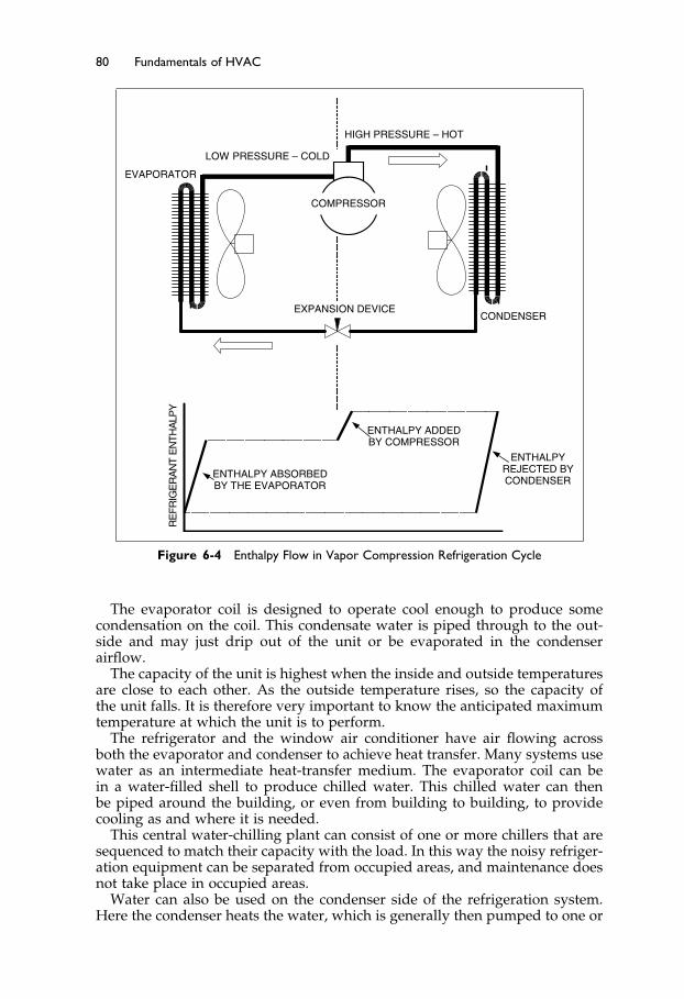
Elsevier UK Ch06-P373998 3-11-2006 7:33a.m. Page:80 Trimsize:6.5×9.5inches
Basal Font:Palatino Margins:Top:40pt Gutter:55pt Font Size:10/11 Text Width:29pc Depth:51 Lines
80 Fundamentals of HVAC
EXPANSION DEVICE
COMPRESSOR
CONDENSER
HIGH PRESSURE – HOT
LOW PRESSURE – COLD
EVAPORATORY
PLA
HT
NE
TN
AR
EGI
RFE
R
ENTHALPY ABSORBEDBY THE EVAPORATOR
ENTHALPY ADDEDBY COMPRESSOR
ENTHALPYREJECTED BYCONDENSER
Figure 6-4 Enthalpy Flow in Vapor Compression Refrigeration Cycle
The evaporator coil is designed to operate cool enough to produce somecondensation on the coil. This condensate water is piped through to the out-side and may just drip out of the unit or be evaporated in the condenserairflow.
The capacity of the unit is highest when the inside and outside temperaturesare close to each other. As the outside temperature rises, so the capacity ofthe unit falls. It is therefore very important to know the anticipated maximumtemperature at which the unit is to perform.
The refrigerator and the window air conditioner have air flowing acrossboth the evaporator and condenser to achieve heat transfer. Many systems usewater as an intermediate heat-transfer medium. The evaporator coil can bein a water-filled shell to produce chilled water. This chilled water can thenbe piped around the building, or even from building to building, to providecooling as and where it is needed.
This central water-chilling plant can consist of one or more chillers that aresequenced to match their capacity with the load. In this way the noisy refriger-ation equipment can be separated from occupied areas, and maintenance doesnot take place in occupied areas.
Water can also be used on the condenser side of the refrigeration system.Here the condenser heats the water, which is generally then pumped to one or

Elsevier UK Ch06-P373998 3-11-2006 7:33a.m. Page:81 Trimsize:6.5×9.5inches
Basal Font:Palatino Margins:Top:40pt Gutter:55pt Font Size:10/11 Text Width:29pc Depth:51 Lines
Single Zone Air Handlers and Unitary Equipment 81
Figure 6-5 Window Air Conditioner
more cooling towers. A cooling tower is a piece of equipment for cooling waterby evaporation. The warmed condenser water enters at the top through a seriesof nozzles, which spread the water over an array of wooden or plastic surfaces.Most cooling towers also have a fan to force air through the surfaces, causingsome of the water to evaporate and cool the remaining water. The cooled waterflows down into a sump, to be pumped back through the condenser.
Heat Pump
The previous discussion is focused on pumping heat from a cooled space andrejecting heat to outside. There are times when the reverse process is valuable.If the outside temperature is not too cold, one could install a window airconditioner back-to-front. Then, it would cool outside and warm inside. Thetotal heat rejected to the inside would be the sum of the electrical energy putinto the compressor, plus heat absorbed from the outside air. It would bepumping the heat into the space – hence we call it a heat pump. In milderclimates, a heat pump can obtain useful heat from the ambient air.
In practice, one does not take out the window air conditioner and installit the other-way-round for heating, since the reversal can be achieved with aspecial valve in the refrigeration circuit. Figure 6-6 shows the heat pump circuit.

Elsevier UK Ch06-P373998 3-11-2006 7:33a.m. Page:82 Trimsize:6.5×9.5inches
Basal Font:Palatino Margins:Top:40pt Gutter:55pt Font Size:10/11 Text Width:29pc Depth:51 Lines
82 Fundamentals of HVAC
Figure 6-6 Heat Pump with Reversing Value
It has been drawn slightly differently from the previous two figures, but thecircuit is the same, evaporator, compressor, condenser, and expansion device.In the upper diagram the refrigerant is flowing, as in previous diagrams, andheat is being “pumped” from the inside coil to be rejected by the outside coil.In the lower diagram the reversing valve has been switched to reverse theflow of refrigerant in the inside and outside coils. Heat is now absorbed fromoutside and rejected by the inside coil, heating the inside.
The performance of the air-to-air heat pump drops as the temperature differ-ence increases, so they are not very effective with an outside air temperaturebelow freezing.
Another source of heat, or sink for waste heat, is the ground. In many places,one can lay coils of pipe in the ground, in trenches or in vertical boreholes,and circulate water. The water will be heated by the surrounding soil, if it iscold, and cooled by the surrounding soil if it is hot. In the example, shown

Elsevier UK Ch06-P373998 3-11-2006 7:33a.m. Page:83 Trimsize:6.5×9.5inches
Basal Font:Palatino Margins:Top:40pt Gutter:55pt Font Size:10/11 Text Width:29pc Depth:51 Lines
Single Zone Air Handlers and Unitary Equipment 83
in Figure 6-6, the heat pump has a ground water heated/cooled coil and acooled/heated air coil for the building. Figure 6-6 shows the circuit, includingthe reversing valve operation.
Refrigeration is a very important part of the air-conditioning industry. TheASHRAE Course, Fundamentals of Refrigeration,2 will teach you about the sys-tems, components, system control, and cooling loads.
6.5 System Performance Requirements
Before choosing a system, you need an understanding of the types of loadsyou want the system to manage. Typically, the summer cooling loads willbe the main determinant of the choice of unit. The heating loads are usuallydealt with easily by choosing a suitable heater to go with the chosen unit. Thesummer loads, though, will be dependent on several, somewhat interrelatedfactors:
Outside summer design temperature. This affects the cooling load inthree ways:
Interior load—The interior load is calculated using the outside temperatureplus solar heat gain acquired due to heat transfer through the fabric ofthe building.
Outside air temperature—The load from the outside air temperature will alsopartly determine the cooling load of the outside air that is being broughtinto the building for ventilation.
Effectiveness of the refrigeration system—If the refrigeration system is air-cooled, the outside temperature will influence the effectiveness of therefrigeration system.
Outside summer design humidity. The outside design humidity will be afactor in the ventilation air load and the removal of moisture from any air thatleaks into the building. Cooling tower performance is also directly affected bythe humidity; performance falls as humidity rises.
Inside summer design temperature and humidity. The warmer and damperthe inside is allowed to be, the smaller the difference between inside andoutside, hence the lower the load on the system. This is particularly importantwhen you are making system choices.
Slight under-sizing, which is cheaper to buy, means that occasionally thedesign temperatures will be exceeded. However, when the unit is slightlyunder-sized, it will be running nearer full load for more of the time. Dependingon the situation, this may be the most economical choice.
Inside summer generation of heat and moisture. These will be added to thebuilding loads to establish the total loads on the system.
Summer ventilation requirements. This is the ventilation for people, typ-ically based on ASHRAE Standard 62.1-2004, plus any additional ventila-tion for specific equipment. The higher the ventilation requirements, thegreater the load due to cooling and dehumidifying the outside air that isbrought in.
Once these basic criteria are established, load calculation can be done.Depending on the situation, summer cooling and winter heating loads maybe estimated with fairly simple hand calculation methods for the peak-load

Elsevier UK Ch06-P373998 3-11-2006 7:33a.m. Page:84 Trimsize:6.5×9.5inches
Basal Font:Palatino Margins:Top:40pt Gutter:55pt Font Size:10/11 Text Width:29pc Depth:51 Lines
84 Fundamentals of HVAC
summer cooling and for the peak-load winter heating. In other cases, an hour-by-hour computer simulation of the building may be done, in order to assesspeak-load and intermediate-load performance.
The following example illustrates some of the issues for system performance.
EXAMPLE: A building has the following conditions:
The design room condition is 24 �C and 50% relative humidity.The outside design condition is 35 �C and 40% relative humidity.The sensible heat load is 60,000 watts. Sensible heat is heat that causes
change in temperature.The moisture heat load, or “Latent heat” is 6,000 watts. Latent heat is the
energy that is absorbed by water which causes the water to evaporate.
To calculate the loads, first divide the latent load by the sensible load. Thisprovides us with the percentage of sensible heat that must be removed fromthe system.
For example, if the latent load is 6,000 watts per hour and the sensible loadis 60,000 watts, the ratio would be 1/10. With an all-air system, the air supplymust be at a temperature and moisture content that requires 10 times as muchsensible heat as latent heat to reach room temperature. We can plot a line onwhich the air supply must be to meet the design room condition.
You can easily plot this on the psychrometric chart as is shown in Figure 6-7.
First, note the enthalpy of the air at the desired room condition.Draw a vertical line downward from the room condition.Mark on the line where the enthalpy line is 1 kJ/kg less than room conditions.From this point, draw a horizontal line to the left. Mark off where the
enthalpy is 10 kJ/kg less. Depending on the specific chart range it maybe easier to use larger numbers, say 5 kJ/kg and 50 kJ/kg.
Draw a line from here to the room condition.
Figure 6-7 Space, Outside, and Mixed Conditions

Elsevier UK Ch06-P373998 3-11-2006 7:33a.m. Page:85 Trimsize:6.5×9.5inches
Basal Font:Palatino Margins:Top:40pt Gutter:55pt Font Size:10/11 Text Width:29pc Depth:51 Lines
Single Zone Air Handlers and Unitary Equipment 85
This illustrates that, for the supply air to meet the designed room condition,it must be supplied at some point on this line. If it is supplied close to thedesigned room-condition the volume will have to be large.
The calculation of heating loads is relatively straightforward, but cooling-load calculation is more challenging, due to the movement of the sun andchanging loads throughout the day. Calculating heating and cooling loads isthe subject of the ASHRAE Course Fundamentals of Heating and Cooling Loads.3
Decision factors for choosing units
When choosing equipment, several factors must be balanced.
The initial cost to purchase and install versus the ongoing cost of oper-ation and maintenance. Most heating and cooling systems reach peakload very occasionally and then only for a short period of time. Most ofthe time, the equipment is operating at loads much below peak. Equip-ment either improves in efficiency at lower load—a characteristic ofmany boilers—or it falls—a characteristic of many refrigeration units.When choosing refrigeration equipment, it can be very worthwhile toconsider the part-load performance. It is in the part-load performanceevaluation that hour-by-hour computer simulations become a reallynecessary tool.
Load versus capacity. Note that we have been talking about “loads,” butwhen you look in manufacturers’ data sheets, they talk about “plantcapacity.” “Loads” and “capacity” are the same issue, but loads arethe calculated building requirements, while capacity is the plant equip-ment’s ability to handle the load. When purchasing packaged plantequipment, the plant capacity often does not exactly match the calcu-lated building loads. One of the challenges for the designer is choosingthe most suitable package, even though it does not exactly match the cal-culated building loads. This issue is illustrated in the following sectionon rooftop units.
6.6 Rooftop Units
A typical rooftop system is diagrammed in Figure 6-8. The return air is drawnup into the base of the unit and the supply air is blown vertically down fromthe bottom of the unit into the space below. As an alternative, the ducts canproject from the end of the unit to run across the roof before entering thebuilding.
The major advantages of these units are
No working parts in the occupied space—so maintenance can be carried outwithout disrupting activities within the building and maintenance canbe carried out without access to the building when the building is closed.
No space is built for the unit—which saves construction costs.No delay for detailed manufacturer design work—because the unit is pre-
designed.No wide access during construction—because the unit is outside the building
envelope, the contractor does not have to keep an access available forthe unit to be moved in during construction.
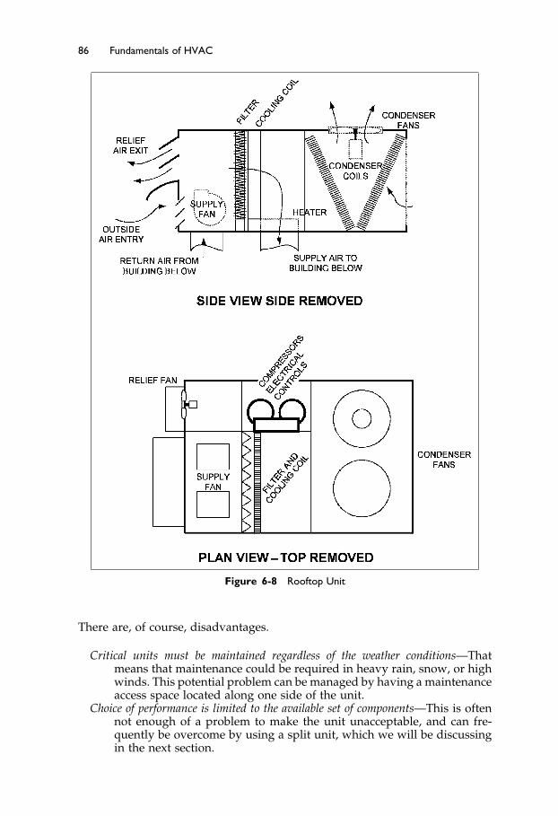
Elsevier UK Ch06-P373998 3-11-2006 7:33a.m. Page:86 Trimsize:6.5×9.5inches
Basal Font:Palatino Margins:Top:40pt Gutter:55pt Font Size:10/11 Text Width:29pc Depth:51 Lines
86 Fundamentals of HVAC
Figure 6-8 Rooftop Unit
There are, of course, disadvantages.
Critical units must be maintained regardless of the weather conditions—Thatmeans that maintenance could be required in heavy rain, snow, or highwinds. This potential problem can be managed by having a maintenanceaccess space located along one side of the unit.
Choice of performance is limited to the available set of components—This is oftennot enough of a problem to make the unit unacceptable, and can fre-quently be overcome by using a split unit, which we will be discussingin the next section.

Elsevier UK Ch06-P373998 3-11-2006 7:33a.m. Page:87 Trimsize:6.5×9.5inches
Basal Font:Palatino Margins:Top:40pt Gutter:55pt Font Size:10/11 Text Width:29pc Depth:51 Lines
Single Zone Air Handlers and Unitary Equipment 87
Choosing a rooftop unit is fairly straightforward. One needs to know bothinside and outside design-temperatures, required airflow, in L/s, mixed-airtemperature, and the required sensible and latent cooling-loads.
The mixed-air temperature can be calculated based on the return-air tem-perature, the outside air temperature and the required proportion of outsideair. Referring back to the example, shown in Figure 6-7, the room temperature,which we will consider to be return temperature, was 23 �C, and the outsideambient temperature was 35 �C. If 20% outside air is required, then the mixedtemperature can be estimated by proportion
35 �C ·0�2+23 �C ·0�8 = 25�4 �C
The calculation of airflow is covered in detail in the ASHRAE Course Fun-damentals of Air System Design.1
It is important for the airflow to be correctly calculated and for the unit tobe set up and balanced to provide the correct airflow. With direct expansionrefrigeration circuits, too little airflow over the evaporator can cause problems:
Imagine that the airflow is much slower than design. The slow speed pastthe coil will allow the air to cool further, and—if the coil is below freezing—forice to start forming. The slow flow will also reduce the heat being absorbedinto the evaporator, so the compressor’s suction will be drawing with littlerefrigerant vapor coming in. As a result, the pressure in the evaporator willfall, causing the evaporator temperature to fall, which will also tend to causefreezing. Once ice formation starts, the ice starts to block the flow, causing evenslower airflow until the coil is encased in ice. Ice formation on the evaporatorcan also be caused by too little refrigerant in the system – a common result ofa slow refrigerant leak.
As noted in the previous discussion of loads versus capacity, air-handlingunits come in discrete sizes, so a perfect match of unit and calculated loadsdoes not happen. From the example in Figure 6-7, for our loads of 60,000 wattssensible load and 6,000 watts latent load, let us assume the closest unit has aperformance of 75,000 watts sensible and 11,000 watts latent capacity.
This looks excessively oversized, but the unit’s sensible capacity does nottake into account the heat from the supply fans in the unit. Suppose the fanload was 5 kW (5,000 watts), then the fan heat added to the cool air would be5,000 watts if the fan and motor are in the air stream.
The effective sensible heat capacity of the unit is thus:
70�000 watts−5�000 watts = 65�000 watts
This is a very close match to the required capacity.The 11,000 watts moisture removal, when compared to the required 6,000
watts, is a common issue in dry climates. The coil removes more moisture thanrequired. There are two results. First, more energy is used than required tomaintain the design conditions. Second, the real conditions will be drier thanthe design condition.
The converse problem, of too little moisture removal, occurs in hot moistclimates, particularly where higher proportions of outside air are required. Inthis case, and others, it may not be possible to find a package rooftop-unit forthe duty and it may be advantageous, or necessary, to take special measuresto remove moisture. Some of these are discussed in Chapter 13.
Heating choices are generally less of an issue, but the designer still has to beaware of potential problems. As noted earlier, electrical heaters are normally

Elsevier UK Ch06-P373998 3-11-2006 7:33a.m. Page:88 Trimsize:6.5×9.5inches
Basal Font:Palatino Margins:Top:40pt Gutter:55pt Font Size:10/11 Text Width:29pc Depth:51 Lines
88 Fundamentals of HVAC
available with stepped capacity, but gas heaters are often on-off or high-low-off. If the unit runs continuously at the gas-heater cycle, the air supply willfluctuate in temperature and sometimes blow warm, and sometimes blow cold.Take care to ensure that the occupants do not have an intermittent cold draftblowing on them.
Having considered the single-zone air handler, with particular emphasis onthe rooftop unit, let us now consider another popular single-zone system, thesplit system.
6.7 Split Systems
In the rooftop unit, all the plant was in a single housing and was purchased as amanufacturer’s pre-design. In general, the package rooftop-units are designedfor popular duties, and to be as light and compact as possible, since they haveto be lifted onto the roof. In the split system, the compressor/condenser partof the refrigeration system is chosen separately from the rest of the system andconnected by the refrigerant lines to the air system, which includes the evap-orator. The pipes, even with their insulation, are only millimeters in diameter,compared to ducts that are, typically, hundreds of millimeters in diameter.The separation of the two parts of the refrigeration system to produce the splitsystem is diagrammed in Figure 6-9. The system can range in size from thesmall residential systems where the inside coil is mounted on the furnace airoutlet to substantial commercial units serving a building.
The split system allows the designer a much greater choice of performance.For example, designing a unit for operation in an ice rink requires a low spacetemperature, hence a non-package situation. This requirement is well suitedto the flexibility of the split system.
The other main advantage of the split system is that it allows the air handlingpart of the unit to be indoors, where it is easier to maintain and does notneed to be weatherproofed. The noise of the compressor is outside and canbe located at some distance from the air-handling unit. For example, in athree-story building, all the condensers can be mounted on the roof, whilethe air handlers are on the floor they serve. This allows the ducting to berun horizontally on each floor and only requires a small vertical duct for therefrigerant lines from the three units to the roof.
Figure 6-9 Split System
Elsevier UK Ch06-P373998 3-11-2006 7:33a.m. Page:89 Trimsize:6.5×9.5inches
Basal Font:Palatino Margins:Top:40pt Gutter:55pt Font Size:10/11 Text Width:29pc Depth:51 Lines
Single Zone Air Handlers and Unitary Equipment 89
The Next Step
We have considered single zone air-conditioning systems in this chapter. Wefocused on rooftop and split systems. We considered the components theycontain, how the components operate and some of the limitations of off-the-shelf equipment. Finally we looked at a simple choice of rooftop and spiltsystem and the resulting space conditions.
In the next chapter we will look at how these single zone systems can bemodified to produce multi-zone systems.
Summary
In this chapter, we discussed issues of system choice and provided a generaldescription of system control issues. We will return to controls in more depthin Chapter 11.
6.2 Examples of Buildings with Single Zone Package Air-ConditioningUnits
For heating and cooling, a packaged unit may require only an electrical sourceof power, or a gas or hot water supply, and/or a source of chilled water. Thebasic operation of the unit stays the same; it is just the source of heating andcooling energy that may change.
6.3 Air-Handling Unit Components
The overall functions of the air handler are to draw in outside air and returnair, mix them, condition the mixed air, blow the conditioned air into the space,and exhaust any excess air to outside. Components of the unit can include: inletlouver screen, the parallel blade damper, opposed blade damper, the reliefair damper, actuator, the mixed temperature sensor, filter heating coil, coolingcoil, humidifier, fan, return fan. The concept of control logic was introducedas a method to summarize the operation of the components of the system.
6.4 The Refrigeration Cycle
The vapor compression refrigeration cycle is generally the basis of mechani-cal refrigeration. The vapor compression refrigeration system comprises fourcomponents: compressor, condenser, expansion valve, and evaporator. Thissystem can be used directly, to provide cooling to, typically, a local coil. Toprovide cooling for several coils at greater distances, refrigeration machinesare used to chill water that is then pumped around buildings to provide cool-ing in air-conditioning systems. The heat removed from the water is expelledinto the atmosphere through a hot, air-cooled coil, or by evaporating water ina cooling tower.
The components are matched to work together with a specific charge ofrefrigerant. If you operate the system with too little refrigerant or too little airor water flow over the evaporator or condenser, problems can arise.

Elsevier UK Ch06-P373998 3-11-2006 7:33a.m. Page:90 Trimsize:6.5×9.5inches
Basal Font:Palatino Margins:Top:40pt Gutter:55pt Font Size:10/11 Text Width:29pc Depth:51 Lines
90 Fundamentals of HVAC
While cooling is achieved by pumping heat from a cooled space and reject-ing heat to outside, you can reverse the process, in a mild climate, with aheat pump, to obtain heat from ambient air. Similarly, the ground can beused as a source of heat or a sink for waste heat, by using a ground sourceheat pump.
6.5 System Performance Requirements
Before choosing a system, you need an understanding of the types of loadsyou want the system to manage. Summer cooling loads will be the maindeterminant of the choice of unit. These summer factors are used to deter-mine the summer load: outside design temperature; outside design humid-ity; inside design temperature and humidity; inside generation of heat andmoisture; ventilation requirements. Once you have determined summer loads,additional decision factors for unit choice are the initial cost to purchase andinstall, versus the ongoing cost of operation and maintenance; and load versuscapacity.
6.6 Rooftop Units
In a typical rooftop unit, the return air is drawn up into the base of the unitand the supply air is blown vertically down from the bottom of the unit intothe space below. As an alternative, the ducts can come out of the end ofthe unit to run across the roof before entering the building. Advantages anddisadvantages of rooftop units were discussed.
Factors to choose a rooftop unit: inside and outside design temperatures,required airflow in L/s, mixed air temperature, and the required sensible andlatent cooling loads.
It is important for the airflow to be correctly calculated and for the unit tobe set up and balanced to provide the correct airflow. With direct expansionrefrigeration circuits, too little airflow over the evaporator can cause icingproblems.
Units come in discrete sizes, so a perfect match of unit and calculated loadsdoes not happen. As a result, the design conditions may be jeopardized, and/orextra energy costs may arise.
6.7 Split Systems
In the split system, the compressor/condenser part of the refrigeration systemis separate from the evaporator coil and connected by the refrigerant lines tothe air system, which includes the evaporator.
Advantages of the split system: It allows the designer a much greater choiceof performance; it allows the air handling part of the unit to be indoors, whereit is easier to maintain and does not need to be weatherproofed. The noiseof the compressor is outside and can be located at some distance from theair-handling unit.
Elsevier UK Ch06-P373998 3-11-2006 7:33a.m. Page:91 Trimsize:6.5×9.5inches
Basal Font:Palatino Margins:Top:40pt Gutter:55pt Font Size:10/11 Text Width:29pc Depth:51 Lines
Single Zone Air Handlers and Unitary Equipment 91
Bibliography
1. ASHRAE. 1998. Fundamentals of Air System Design. Atlanta: American Society ofHeating, Refrigerating and Air-Conditioning Engineers, Inc.
2. ASHRAE. 1999. Fundamentals of Refrigeration. Atlanta: American Society of Heating,Refrigerating and Air-Conditioning Engineers, Inc.
3. ASHRAE. 1998. Fundamentals of Heating and Cooling Loads. Atlanta: American Societyof Heating, Refrigerating and Air-Conditioning Engineers, Inc.
Elsevier UK Ch07-P373998 3-11-2006 7:33a.m. Page:92 Trimsize:6.5×9.5inches
Basal Font:Palatino Margins:Top:40pt Gutter:55pt Font Size:10/11 Text Width:29pc Depth:51 Lines
Chapter 7
Multiple Zone Air Systems
Contents of Chapter 7
InstructionsObjectives of Chapter 77.1 Introduction7.2 Single-Duct, Zoned-Reheat, Constant-Volume Systems7.3 Single-Duct, Variable-Air-Volume Systems (VAV)7.4 Bypass Box Systems7.5 Constant-Volume, Dual-Duct, All-Air Systems7.6 Multizone Systems7.7 Three-Deck Multizone Systems7.8 Dual-Duct, Variable-Air-Volume Systems7.9 Dual-Path Outside-Air SystemsThe Next StepSummary
Instructions
Read the chapter. Re-read the parts of the chapter that are emphasized in thesummary and memorize important definitions.
Objectives of Chapter 7
Chapter 7 shows the most common ways that a single-supply air system canbe adapted to provide all-air air conditioning to many zones with differingloads. After studying the chapter, you should be able to:
Identify, describe, and diagrammatically sketch the most common all-airair-conditioning systems.
Understand the relative efficiency or inefficiency of each type of multiplezone air system.
Explain why systems that serve many zones, and that have a variable-supplyair volume, are more energy-efficient than those with constant-supplyvolumes.
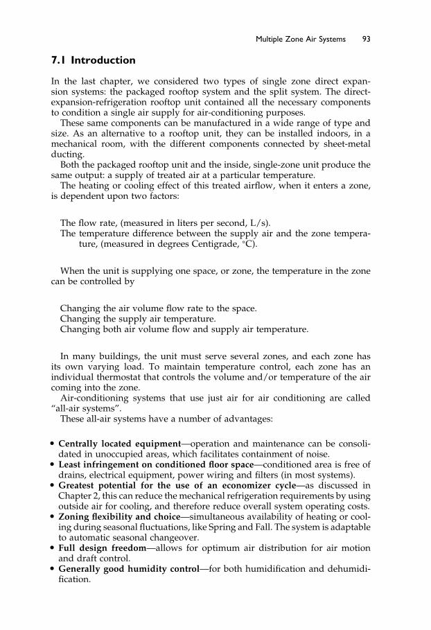
Elsevier UK Ch07-P373998 3-11-2006 7:33a.m. Page:93 Trimsize:6.5×9.5inches
Basal Font:Palatino Margins:Top:40pt Gutter:55pt Font Size:10/11 Text Width:29pc Depth:51 Lines
Multiple Zone Air Systems 93
7.1 Introduction
In the last chapter, we considered two types of single zone direct expan-sion systems: the packaged rooftop system and the split system. The direct-expansion-refrigeration rooftop unit contained all the necessary componentsto condition a single air supply for air-conditioning purposes.
These same components can be manufactured in a wide range of type andsize. As an alternative to a rooftop unit, they can be installed indoors, in amechanical room, with the different components connected by sheet-metalducting.
Both the packaged rooftop unit and the inside, single-zone unit produce thesame output: a supply of treated air at a particular temperature.
The heating or cooling effect of this treated airflow, when it enters a zone,is dependent upon two factors:
The flow rate, (measured in liters per second, L/s).The temperature difference between the supply air and the zone tempera-
ture, (measured in degrees Centigrade, �C).
When the unit is supplying one space, or zone, the temperature in the zonecan be controlled by
Changing the air volume flow rate to the space.Changing the supply air temperature.Changing both air volume flow and supply air temperature.
In many buildings, the unit must serve several zones, and each zone hasits own varying load. To maintain temperature control, each zone has anindividual thermostat that controls the volume and/or temperature of the aircoming into the zone.
Air-conditioning systems that use just air for air conditioning are called“all-air systems”.
These all-air systems have a number of advantages:
• Centrally located equipment—operation and maintenance can be consoli-dated in unoccupied areas, which facilitates containment of noise.
• Least infringement on conditioned floor space—conditioned area is free ofdrains, electrical equipment, power wiring and filters (in most systems).
• Greatest potential for the use of an economizer cycle—as discussed inChapter 2, this can reduce the mechanical refrigeration requirements by usingoutside air for cooling, and therefore reduce overall system operating costs.
• Zoning flexibility and choice—simultaneous availability of heating or cool-ing during seasonal fluctuations, like Spring and Fall. The system is adaptableto automatic seasonal changeover.
• Full design freedom—allows for optimum air distribution for air motionand draft control.
• Generally good humidity control—for both humidification and dehumidi-fication.

Elsevier UK Ch07-P373998 3-11-2006 7:33a.m. Page:94 Trimsize:6.5×9.5inches
Basal Font:Palatino Margins:Top:40pt Gutter:55pt Font Size:10/11 Text Width:29pc Depth:51 Lines
94 Fundamentals of HVAC
All-air systems generally have the following disadvantages:
• Increased space requirements—significant additional duct space require-ments for duct risers and ceiling distribution ducts.
• Construction dust—due to problems with construction-dust, all-air systemsare generally available for heating later in the construction schedule thansystems that use water to convey heat.
• Closer coordination required—all-air systems call for close cooperationbetween architectural, mechanical and structural designers.
In addition to these general disadvantages, constant-volume-reheat systemsare particularly high energy consumers because they first cool the air, and thenreheat it. Because the reheat coils are sometimes hot water coils, an additionalpotential disadvantage is a problem with leaking hot-water coils. We willdiscuss these systems in more detail in the next section.
To make these all-air systems work for many zones requires some form ofzone control. In this chapter we will consider how zone control can be achievedwith all-air air-conditioning systems.
The simplest, and one that we will start with, is the constant-volume-reheatsystem.
7.2 Single-Duct, Zoned-Reheat, Constant-Volume Systems
The reheat system is a modification of the single-zone system. The reheatsystem permits zone control by reheating the cool airflow to the temperaturerequired for a particular zone. Figure 7-1 shows a reheat system, with ceilingsupply diffusers in the space.
A constant volume of conditioned air is supplied from a central unit at a nor-mally, fixed temperature, (typically 13 �C). This fixed temperature is designedto offset the maximum cooling load in all zones of the space. If the actualcooling load is less than peak, then the reheat coil provides heat equal to thedifference between the peak and actual loads. When heating is required, theheater heats the air above zone temperature to provide heating.
Figure 7-1 Reheat System

Elsevier UK Ch07-P373998 3-11-2006 7:33a.m. Page:95 Trimsize:6.5×9.5inches
Basal Font:Palatino Margins:Top:40pt Gutter:55pt Font Size:10/11 Text Width:29pc Depth:51 Lines
Multiple Zone Air Systems 95
The reheat coil is located close to the zone and it is controlled by the zonethermostat. Reheat coils are usually hot water or electric coils. As noted above,if the reheat coils are hot water, then there can be a problem with leakage.
A reheat system is often used in hospitals, in laboratories, or other spaceswhere wide load-variations are expected.
When primary air passes quickly over a vent, it draws some room air intothe vent. This process is called induction. There are two variations on thereheat system that both use induced room air: the Induction Reheat Unit,shown in Figure 7-2; and the Low-Temperature Reheat Unit with Induced Airshown in Figure 7-3.
The Induction Reheat Unit shown in Figure 7-2 shows the primary supplyof air, blown into the unit and directed through the induction nozzle. Thereduced aperture of the nozzle forces the air to speed up and move quickly tothe unit exit, into the room. As the primary air passes quickly past the reheatcoil, it draws, or induces, air from the room into the unit. The room air passesacross the reheat coil and mixes with the primary air.
Units like this are often mounted beneath windows, where they offset anydowndraft in cold weather. In addition, even when the air supply is turned“off,” hot water in the coil will still provide some heating.
The second type of induction reheat system, the Low-Temperature ReheatUnit with Induced Air, shown in Figure 7-3, is used where very cold supplyair is provided. In some systems, the supply air can be as cold as 4 �C. Thiscould create intolerable drafts and serious condensation on the supply outlets.In this system, the primary air is preheated when necessary, but room air is
Figure 7-2 Induction Reheat Unit

Elsevier UK Ch07-P373998 3-11-2006 7:33a.m. Page:96 Trimsize:6.5×9.5inches
Basal Font:Palatino Margins:Top:40pt Gutter:55pt Font Size:10/11 Text Width:29pc Depth:51 Lines
96 Fundamentals of HVAC
Figure 7-3 Low-Temperature Reheat Unit with Induced Air
always induced to mix with the primary air to ensure that the flow into thespace is not excessively cold.
There are two primary advantages to this system:
• Duct sizing: When the system is designed to use 4 �C supply air, ducts canbe sized for half the air volume, compared to the ducts required for a 13 �Csupply-air temperature. This results in a lower installation cost, and a smallerrequirement for duct space.
• The small volume of supply air may be exhausted from the room rather thanreturned to the main cooling system, possibly eliminating the need for returnductwork.
Overall, reheat systems are simple, and initial costs, the costs of design andconstruction, are reasonable. Reheat systems provide good humidity control,good temperature control, good air circulation, and good air quality.
The problem with all reheat systems is their energy inefficiency, so theyare expensive systems to run. Generally, when the load is less than the peakcooling load, the cooling effect and the reheat are working against each otherto neutralize their contributions. This means, in a no-load situation, the refrig-eration is going at full blast and the reheat is just matching the cooling effect.There are two energy drains for no load! This is not quite as severe as it soundsbecause the no-load condition is the worst-case scenario, and it only occurs fora relatively small amount of the time.
Overall, though, reheat is energy expensive. As a result, these systems havefallen out of favor in recent times.
7.3 Single-Duct, Variable-Air-Volume Systems (VAV)
Buildings that are located in continuously warm climates, and interior spacesin any climate, require no heating, only cooling. For cooling-only situations,

Elsevier UK Ch07-P373998 3-11-2006 7:33a.m. Page:97 Trimsize:6.5×9.5inches
Basal Font:Palatino Margins:Top:40pt Gutter:55pt Font Size:10/11 Text Width:29pc Depth:51 Lines
Multiple Zone Air Systems 97
it would be ideal to supply only as much cooling and ventilation as the zoneactually requires at the particular moment. A system that comes close to theideal is the variable-air-volume system, “VAV.”
The variable air volume system is designed with a volume control damper,controlled by the zone thermostat, in each zone. This damper acts as a throttleto allow more or less cool air into the zone. The VAV system adjusts forvarying cooling loads in different zones by individually throttling the supplyair volume to each zone. Regardless of the variations in the cooling load, aminimum flow of ventilation air is always provided and care must be takento ensure that the required volume of ventilation air is provided.
In a VAV system, as the zone becomes cooler, the cooling load decreasesand the cool airflow to the zone decreases. Eventually it reaches the minimumvalue necessary for adequate ventilation and air supply, Figure 7-4. When thisminimum airflow is reached, if the zone is still too cool, heating is providedby a thermostatically controlled reheat coil or a baseboard heater.
This means there may be some energy wasted in the VAV system, due toheating and cooling at the same time. However, this energy waste is far lessthan in the terminal reheat system, since the cooling ventilation air is reducedto a minimum before the heating starts.
The total supply-airflow rate in a VAV system will vary as the zone dampersadjust the flow to each zone. Therefore, the supply fan must be capable ofvarying its flow rate. The variation in flow rate must be achieved withoutallowing the duct pressure to rise excessively or to drop below the pressurerequired by the VAV boxes for their proper operation. This pressure controlis often achieved by using a pressure sensor in the duct to adjust a fan-speedcontrol unit. Similarly, the return fan is controlled to meet the varying supply-air volume.
There are other methods that are discussed in the ASHRAE Course, Funda-mentals of Air System Design.
In systems where the fan speed is reduced to reduce the volume flow, thefan power drops substantially as the flow reduces. This reduction in fan poweris a major contribution to the economy of the VAV system.
VAV systems may have variable volume return air fans that are controlled bypressure in the building or are controlled to track the supply-fan volume flow.
In small systems, the variable-volume supply may be achieved by using arelief damper, called a “bypass,” at the air-handling unit. The bypass allowsair from the supply duct through a control damper into the return duct, asshown in Figure 7-5.
Figure 7-4 Variable Air Volume System

Elsevier UK Ch07-P373998 3-11-2006 7:33a.m. Page:98 Trimsize:6.5×9.5inches
Basal Font:Palatino Margins:Top:40pt Gutter:55pt Font Size:10/11 Text Width:29pc Depth:51 Lines
98 Fundamentals of HVAC
Figure 7-5 Variable-Air-Volume System with Bypass
As the zones reduce their air requirements, the bypass damper opens tomaintain constant flow through the supply fan. This arrangement allows for theconstant volume required by the refrigeration circuit. For smaller systems, thismethod can provide very effective zone control without creating problems thatmay occur when the airflow is varied across the direct expansion refrigerationcoil. Unfortunately, this system keeps the fan working at near full load.
VAV Advantages
Advantages of the variable volume system are the low initial costs and lowoperating costs. Initial costs are low because the system only requires singleruns of duct and a simple control at the end of the duct. Operating costsare low because the volume of air, and therefore the refrigeration and fanpower, closely follow the actual load of the building. There is little of thecool-and-reheat inefficiency of the reheat system.
VAV Problems
There are potential problem areas with variable air volume systems. Theseinclude: poor air circulation in the conditioned space at lower flows; dumpingof cold air into an occupied zone at low flows; and inadequate fresh air suppliedto the zone. Improved diffusers have made it possible for the designer to avoiddumping and poor room circulation. However, the problem of inadequateoutside air for ventilation needs additional care when the system is beingdesigned.
For example, as we saw in the last chapter, in a constant volume systemwhere all the zones require 20% outside air, setting the outside air to 20%on the main unit ensures that each zone receives 20% outside air. In theVAV system, one cannot set the outside air proportion. As the zone flows arereduced due to low thermal load, the proportion of outside-air-for-ventilationneeds to increase. As a result, the outside-air volume must be maintained atall volume flows. This can be achieved in a number of ways, but the processrequires a sophisticated, and potentially more expensive control system thatis not required in constant volume systems.
7.4 Bypass Box Systems
Where the main supply unit must handle a constant volume of air, bypassboxes can provide a variable volume of air to the zones served. The bypass
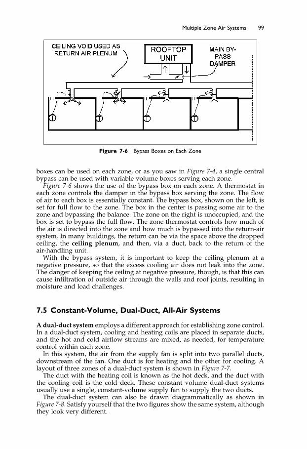
Elsevier UK Ch07-P373998 3-11-2006 7:33a.m. Page:99 Trimsize:6.5×9.5inches
Basal Font:Palatino Margins:Top:40pt Gutter:55pt Font Size:10/11 Text Width:29pc Depth:51 Lines
Multiple Zone Air Systems 99
Figure 7-6 Bypass Boxes on Each Zone
boxes can be used on each zone, or as you saw in Figure 7-4, a single centralbypass can be used with variable volume boxes serving each zone.
Figure 7-6 shows the use of the bypass box on each zone. A thermostat ineach zone controls the damper in the bypass box serving the zone. The flowof air to each box is essentially constant. The bypass box, shown on the left, isset for full flow to the zone. The box in the center is passing some air to thezone and bypassing the balance. The zone on the right is unoccupied, and thebox is set to bypass the full flow. The zone thermostat controls how much ofthe air is directed into the zone and how much is bypassed into the return-airsystem. In many buildings, the return can be via the space above the droppedceiling, the ceiling plenum, and then, via a duct, back to the return of theair-handling unit.
With the bypass system, it is important to keep the ceiling plenum at anegative pressure, so that the excess cooling air does not leak into the zone.The danger of keeping the ceiling at negative pressure, though, is that this cancause infiltration of outside air through the walls and roof joints, resulting inmoisture and load challenges.
7.5 Constant-Volume, Dual-Duct, All-Air Systems
A dual-duct system employs a different approach for establishing zone control.In a dual-duct system, cooling and heating coils are placed in separate ducts,and the hot and cold airflow streams are mixed, as needed, for temperaturecontrol within each zone.
In this system, the air from the supply fan is split into two parallel ducts,downstream of the fan. One duct is for heating and the other for cooling. Alayout of three zones of a dual-duct system is shown in Figure 7-7.
The duct with the heating coil is known as the hot deck, and the duct withthe cooling coil is the cold deck. These constant volume dual-duct systemsusually use a single, constant-volume supply fan to supply the two ducts.
The dual-duct system can also be drawn diagrammatically as shown inFigure 7-8. Satisfy yourself that the two figures show the same system, althoughthey look very different.
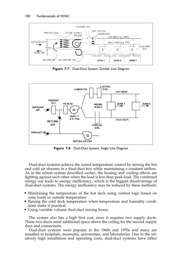
Elsevier UK Ch07-P373998 3-11-2006 7:33a.m. Page:100 Trimsize:6.5×9.5inches
Basal Font:Palatino Margins:Top:40pt Gutter:55pt Font Size:10/11 Text Width:29pc Depth:51 Lines
100 Fundamentals of HVAC
Figure 7-7 Dual-Duct System, Double Line Diagram
Figure 7-8 Dual-Duct System, Single Line Diagram
Dual-duct systems achieve the zoned temperature control by mixing the hotand cold air streams in a dual-duct box while maintaining a constant airflow.As in the reheat system described earlier, the heating and cooling effects arefighting against each other when the load is less than peak load. The combinedenergy use leads to energy inefficiency, which is the biggest disadvantage ofdual-duct systems. The energy inefficiency may be reduced by these methods:
• Minimizing the temperature of the hot deck using control logic based onzone loads or outside temperature
• Raising the cold deck temperature when temperature and humidity condi-tions make it practical
• Using variable volume dual-duct mixing boxes.
The system also has a high first cost, since it requires two supply ducts.These two ducts need additional space above the ceiling for the second supplyduct and connections.
Dual-duct systems were popular in the 1960s and 1970s and many areinstalled in hospitals, museums, universities, and laboratories. Due to the rel-atively high installation and operating costs, dual-duct systems have fallen

Elsevier UK Ch07-P373998 3-11-2006 7:33a.m. Page:101 Trimsize:6.5×9.5inches
Basal Font:Palatino Margins:Top:40pt Gutter:55pt Font Size:10/11 Text Width:29pc Depth:51 Lines
Multiple Zone Air Systems 101
Figure 7-9 Airflow in a Dual-Duct System
out of favor except in hospitals and laboratories, where their ability to servehighly variable sensible-heat loads at constant airflow makes them attractive.Another advantage of dual-duct systems is that there are no reheat coils nearthe zones, so the problems of leaking hot water coils is avoided.
The dual-duct system delivers a constant volume of air, with varying per-centages of hot and cold air, as shown in Figure 7-9.
In Figure 7-9, there are plots of percentage flow from the hot and cold airstreams as a function of room temperature. The sum of the hot and cold air-stream percentages always adds up to 100%. For the room temperature setpointrange, also known as the throttling range, of 21 �C to 22 �C, the thermostat willcontrol the hot-air flow linearly, from 100% at 21 �C to 0% at 22 �C. Outside thethrottling-temperature range, the flow is either all hot air or all cold air.
In Figure 7-10, there is a different view of the same process over the throttlingrange.
There are two plots. One plot, the solid line, shows how the delivered airtemperature will vary as the thermostat controls the percentage mixture of hotand cold streams. The delivered air-temperature scale is on the right-hand sideof the graph, and the room-temperature scale is on the horizontal axis.
At a room temperature of 21 �C and below, with 100% hot air, the deliv-ery temperature is at 45 �C. At a room temperature of 22 �C and above,with 100% cold air, the delivery temperature is 13 �C. At room temperaturesbetween 20 �C and 21 �C, the delivery temperature varies linearly with the roomtemperature.
The second plot in Figure 7-10, the dashed line, is that of the net cooling orheating power delivered to the zone to meet the load. The scale for the powervariable is on the vertical axis, on the left-hand side of the graph. Zero power(or no net delivered heating or cooling) is at mid-height on the vertical axis.Above the mid-height there is net heating, and below mid-height there is netcooling.

Elsevier UK Ch07-P373998 3-11-2006 7:33a.m. Page:102 Trimsize:6.5×9.5inches
Basal Font:Palatino Margins:Top:40pt Gutter:55pt Font Size:10/11 Text Width:29pc Depth:51 Lines
102 Fundamentals of HVAC
Figure 7-10 Delivered Air Temperature in a Dual-Duct System
It is important to observe that, because this is a constant volume system,zero power does not mean zero energy use. Zero power corresponds to an equalamount of heating and cooling, so that the heating and cooling effects canceleach other out, and give a neutral temperature effect on the zone.
As shown in Figure 7-9, below a room temperature of 21 �C, the flow is 100%heating at 45 �C; and above a room temperature of 22 �C, the flow is 100%cooling at 13 �C. Between 21 �C and 22 �C, the flow is a linear mixture of hotand cold air.
7.6 Multizone Systems
The multizone system is thermodynamically the same as the dual-duct system.They both involve mixing varying proportions of a hot-air stream with a cold-air stream to obtain the required supply temperature for that zone. In thedual-duct system, the mixing occurs close to the zone, in the dual-duct box. Inthe multizone system, as shown in Figure 7-11, the mixing occurs at the mainair-handling unit
The basic multizone system has the fan blowing the mixed air over a heatingcoil and a cooling coil in parallel configuration. As you know, in the dual-duct system, the resulting hot and cold air is ducted through the building todual-duct mixing boxes. In contrast, in the multizone system, the heating andcooling airflows are mixed in the air-handling unit at the coils using pairs ofdampers.
The hot deck coil is arranged above the cold deck coil and they are sectionedoff into zones; just two sections are shown in the figure. Each section has atwo-section damper that opens to the cold deck as it closes to the hot deck.Each damper pair is driven by an actuator pushing the crank at the end of thedamper shaft. The mixed air from each section is then ducted to a zone.

Elsevier UK Ch07-P373998 3-11-2006 7:33a.m. Page:103 Trimsize:6.5×9.5inches
Basal Font:Palatino Margins:Top:40pt Gutter:55pt Font Size:10/11 Text Width:29pc Depth:51 Lines
Multiple Zone Air Systems 103
Figure 7-11 Mixing at the Air-Conditioning Unit in a Multizone System
As in the dual-duct system, a certain amount of energy inefficiency occursbecause the air is being both heated and cooled at the same time.
7.7 Three-Deck Multizone Systems
The three-deck multizone system is a possible solution to overcome the energyinefficiency of the overlapping use of heating and cooling in a traditionalmultizone system.
The three-deck system is similar to the dual-duct and multizone systems,except that there is an additional (third) air stream that is neither heated norcooled. Hot and cold air are never mixed in the three-deck system. Instead,thermal zones that require cooling receive a mixture of cold and neutral air,and thermal zones that require heating receive a mixture of hot and neutralair. The airflow control is shown in Figure 7-12. Thus, the three-deck systemavoids the energy waste due to the mixing of hot and cold air streams.
Figure 7-12 Airflow for Three-deck, Multizone System
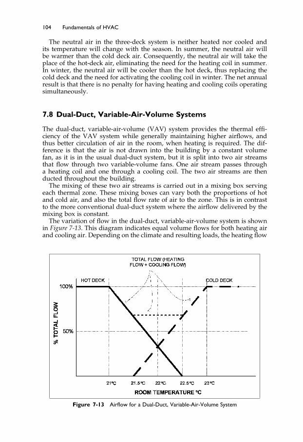
Elsevier UK Ch07-P373998 3-11-2006 7:33a.m. Page:104 Trimsize:6.5×9.5inches
Basal Font:Palatino Margins:Top:40pt Gutter:55pt Font Size:10/11 Text Width:29pc Depth:51 Lines
104 Fundamentals of HVAC
The neutral air in the three-deck system is neither heated nor cooled andits temperature will change with the season. In summer, the neutral air willbe warmer than the cold deck air. Consequently, the neutral air will take theplace of the hot-deck air, eliminating the need for the heating coil in summer.In winter, the neutral air will be cooler than the hot deck, thus replacing thecold deck and the need for activating the cooling coil in winter. The net annualresult is that there is no penalty for having heating and cooling coils operatingsimultaneously.
7.8 Dual-Duct, Variable-Air-Volume Systems
The dual-duct, variable-air-volume (VAV) system provides the thermal effi-ciency of the VAV system while generally maintaining higher airflows, andthus better circulation of air in the room, when heating is required. The dif-ference is that the air is not drawn into the building by a constant volumefan, as it is in the usual dual-duct system, but it is split into two air streamsthat flow through two variable-volume fans. One air stream passes througha heating coil and one through a cooling coil. The two air streams are thenducted throughout the building.
The mixing of these two air streams is carried out in a mixing box servingeach thermal zone. These mixing boxes can vary both the proportions of hotand cold air, and also the total flow rate of air to the zone. This is in contrastto the more conventional dual-duct system where the airflow delivered by themixing box is constant.
The variation of flow in the dual-duct, variable-air-volume system is shownin Figure 7-13. This diagram indicates equal volume flows for both heating airand cooling air. Depending on the climate and resulting loads, the heating flow
Figure 7-13 Airflow for a Dual-Duct, Variable-Air-Volume System

Elsevier UK Ch07-P373998 3-11-2006 7:33a.m. Page:105 Trimsize:6.5×9.5inches
Basal Font:Palatino Margins:Top:40pt Gutter:55pt Font Size:10/11 Text Width:29pc Depth:51 Lines
Multiple Zone Air Systems 105
may be 50% less than the cooling airflow, but the control logic is the same. Atmaximum cooling load, the box provides sufficient cold air to meet the load.As the cooling load decreases, the volume of cold air is decreased, withoutaddition of hot air to change the temperature. When the cooling load reachesthe point where the cold airflow equals the minimum allowable flow, the coldflow continues to decrease, but the hot air is added to maintain sufficient totalflow. As the heating load increases, the total flow remains constant while itstemperature is increased above room temperature by increasing the proportionof air from the hot deck. When the cold deck flow reaches zero, the temperatureof the delivered air will be the hot deck temperature. As the heating loadincreases further, the requirement for more heat is satisfied by increasing thevolume flow rate of hot air.
7.9 Dual-Path Outside-Air Systems
Throughout this text, our examples have shown the outside ventilation airbeing mixed with return air before being processed and supplied to the build-ing. This mixing method works well in cooler, dryer climates. This does notwork as well in warm/hot, humid climates. The reason is very simple: the maincooling coil cannot remove enough moisture without overcooling the wholeair stream. What is required is high moisture removal without full cooling.
An effective way around this problem is to use a dual path system. Theoutside air comes in through a separate, dedicated cooling coil before mixingwith the return air. This dedicated outdoor air coil has two functions:
1. Dehumidification: The system is designed and operated to dehumidify theoutside air to a little below the required space-moisture content.
2. Cooling: The system cools the outside air to about the same temperature asthe main coil, when the main coil is at maximum cooling.
When the system is in operation, the fully cooled outside air, say 20%, mixeswith 80% return air before it reaches the main cooling coil. The mixture isequivalent to the full airflow, substantially dehumidified and 20% cooled. Themain cooling coil now provides the required extra cooling that the systemneeds, and a modest, achievable, requirement for dehumidification.
The challenge of providing adequate dehumidification at an acceptable costis an ongoing challenge in moist climates. The dual path method describedabove is one of the many ways available to tackle the challenge of removingmoisture without overcooling.
The Next Step
This chapter has been all about all-air systems that serve many zones. Inmany cases systems with separate water heating and/or cooling can be veryeffective. For instance, in a very cold climate, it is often more comfortableto provide a perimeter hot water heating system and use the air system forcooling, ventilation air supply, and fine temperature control. This also allowsthe air system to be turned off when the building is unoccupied, even thoughthe heating system must remain on to prevent over-cooling or freezing.
Elsevier UK Ch07-P373998 3-11-2006 7:33a.m. Page:106 Trimsize:6.5×9.5inches
Basal Font:Palatino Margins:Top:40pt Gutter:55pt Font Size:10/11 Text Width:29pc Depth:51 Lines
106 Fundamentals of HVAC
In Chapter 8 we will consider water systems and how they coordinate withair systems we have discussed in this chapter and the previous one.
Summary
This chapter has introduced the various ways zoning can be achieved withall-air air-conditioning systems. They are all based on individually varying theair flow and/or temperature supplied to each zone.
7.2 The Reheat System
Reheat is the simplest system, known both for its reliability and its high energywastage. Two induction variations were introduced: one that also providessome night time heating; and the other that accommodates very low supply-airtemperatures.
7.3 Variable-Air-Volume (VAV) System
More energy efficient than reheat, VAV is a very flexible system with manyvirtues. When there is a low load, however, it does offer challenges for main-taining adequate ventilation air and good room air distribution.
7.4 The Bypass System
A variation on the VAV system, the bypass system, is suitable for providinggood control in smaller systems, and for constant flow over a direct-expansioncooling coil. Designers must be cautious to ensure that bypassed air goesstraight back to the air conditioning unit, but it is generally a simple systemto design.
7.5 The Dual-Duct System
The system provides full airflow when the system is on, but, like the reheatsystem, suffers from the energy penalty of simultaneous heating and cooling.A very attractive feature of the dual-duct system is that there are no reheatcoils near the zones, so the problems of leaking hot water coils is avoided.
7.6 The Multizone System
A system thermodynamically similar to the dual-duct system, the multizonesystem features a different layout. The multizone system is not as energyefficient as the VAV system, and requires a separate duct to each zone. How-ever, the multizone system has the advantage of requiring no maintenanceoutside the mechanical room, except for the zone temperature-sensors andassociated cable.
Elsevier UK Ch07-P373998 3-11-2006 7:33a.m. Page:107 Trimsize:6.5×9.5inches
Basal Font:Palatino Margins:Top:40pt Gutter:55pt Font Size:10/11 Text Width:29pc Depth:51 Lines
Multiple Zone Air Systems 107
7.7 Three-Deck Multizone System
The more modern introduction of the third, neutral duct to the multizonesystem, avoids the conflict of concurrent heating and cooling.
7.8 Dual-Duct, Variable-Air-Volume System
A modification of the dual-duct system, this system uses variable volumedual-duct boxes to provide the thermal efficiency of the VAV system, whilemaintaining higher airflows, and thus better room air circulation when heatingis required.
7.9 Dual-Path Outside-Air System
This system could be used to reduce the problem with excess moisture in theair that arises in warm/hot, humid climates.
Elsevier UK Ch08-P373998 3-11-2006 7:34a.m. Page:108 Trimsize:6.5×9.5inches
Basal Font:Palatino Margins:Top:40pt Gutter:55pt Font Size:10/11 Text Width:29pc Depth:51 Lines
Chapter 8
Hydronic Systems
Contents of Chapter 8
InstructionsObjectives of Chapter 88.1 Introduction8.2 Natural Convection and Low Temperature Radiation Heating
Systems8.3 Panel Heating and Cooling8.4 Fan Coils8.5 Two-Pipe Induction Systems8.6 Water Source Heat PumpsThe Next StepSummaryBibliography
Instructions
Read the material of Chapter 8. Re-read the parts of the chapter that areemphasized in the summary and memorize important definitions.
Objectives of Chapter 8
Chapter 8 introduces hydronic systems, which are also known as water sys-tems. Hydronic systems, in this text, are systems that use water or steam asthe heat transfer medium. In some places, the term “hydronic” has becomeassociated with just radiant floor heating systems, which is a narrower def-inition than we are using in this text. We will discuss radiant floor heatingsystems in Section 8.3, “Panel Heating and Cooling.”
Hydronic systems have their own characteristics, benefits and challenges.After studying the chapter, you should be able to:
Describe five types of hydronic systemsExplain the main benefits of hydronic systemsDiscuss some of the challenges of hydronic systemsExplain the operation and benefits of a water-source heat pump system.
Elsevier UK Ch08-P373998 3-11-2006 7:34a.m. Page:109 Trimsize:6.5×9.5inches
Basal Font:Palatino Margins:Top:40pt Gutter:55pt Font Size:10/11 Text Width:29pc Depth:51 Lines
Hydronic Systems 109
8.1 Introduction
In the previous two chapters, we discussed single zone and multiple-zoneall-air air-conditioning systems. In Chapter 7, Section 7.2, we mentioned thatwater coils could be used in the main airhandling unit and for the reheatcoils in the reheat and VAV systems. In this chapter we are going to considersystems where water-heated and/or water-cooled equipment provide most ofthe heating and/or cooling.
In some buildings, these systems will use low-pressure steam instead ofhot water for heating. The performance is generally similar to hot watersystems, with higher outputs due to the higher temperature of the steam.However, control in these steam systems is generally inferior, due to thefixed temperature of steam. For steam systems and boilers, see Chapters 10and 27, respectively, of the 2000 ASHRAE Handbook—Systems and Equipment.The properties of steam, the theory of two-phase flow and steam pipe siz-ing, are covered in Chapters 6, 4, and 35 of the 2001 ASHRAE Handbook—Fundamentals.
Throughout the rest of this chapter, we will assume that hot water is beingused as the heating medium.
Because of their ability to produce high output on an “as-needed basis,”hydronic systems are most commonly used where high and variable sensibleheating and/or cooling loads occur. These are typically
• Perimeter zones, with high solar heat gains or• Perimeter areas in cooler to cold climates where there are substantial perime-
ter heat losses.
The entrance lobby of a building in a cold climate is an example of an idealuse for these systems. They are frequently used in office buildings, hospitals,hotels, schools, apartment buildings and research laboratories in conjunctionwith ventilation and cooling air systems.
Hydronic systems advantages:• Noise reduction—Virtually silent operation• Economy, due to limited operational costs—Large amounts of heat from
small local equipment• Economy due to limited first costs—Pipes are small compared to ducts for
the same heat transfer around a building• Energy efficiency—Low energy consumption at low load.
Hydronic systems disadvantages:• Ventilation—Provision of outside air for ventilation is either absent or poor• System failure—Danger from freezing and from leaks• Humidity—Control is either absent or generally poor.
We will start our discussion with simple heating systems that operate byallowing heat to escape from a hot surface by natural convection and lowtemperature radiation.
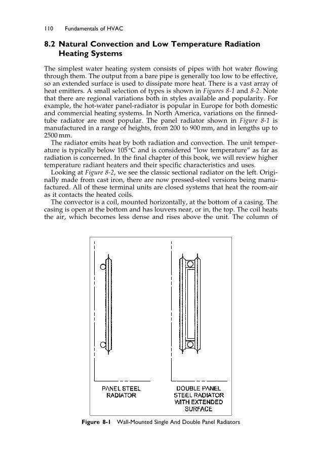
Elsevier UK Ch08-P373998 3-11-2006 7:34a.m. Page:110 Trimsize:6.5×9.5inches
Basal Font:Palatino Margins:Top:40pt Gutter:55pt Font Size:10/11 Text Width:29pc Depth:51 Lines
110 Fundamentals of HVAC
8.2 Natural Convection and Low Temperature RadiationHeating Systems
The simplest water heating system consists of pipes with hot water flowingthrough them. The output from a bare pipe is generally too low to be effective,so an extended surface is used to dissipate more heat. There is a vast array ofheat emitters. A small selection of types is shown in Figures 8-1 and 8-2. Notethat there are regional variations both in styles available and popularity. Forexample, the hot-water panel-radiator is popular in Europe for both domesticand commercial heating systems. In North America, variations on the finned-tube radiator are most popular. The panel radiator shown in Figure 8-1 ismanufactured in a range of heights, from 200 to 900 mm, and in lengths up to2500 mm.
The radiator emits heat by both radiation and convection. The unit temper-ature is typically below 105 �C and is considered “low temperature” as far asradiation is concerned. In the final chapter of this book, we will review highertemperature radiant heaters and their specific characteristics and uses.
Looking at Figure 8-2, we see the classic sectional radiator on the left. Origi-nally made from cast iron, there are now pressed-steel versions being manu-factured. All of these terminal units are closed systems that heat the room-airas it contacts the heated coils.
The convector is a coil, mounted horizontally, at the bottom of a casing. Thecasing is open at the bottom and has louvers near, or in, the top. The coil heatsthe air, which becomes less dense and rises above the unit. The column of
Figure 8-1 Wall-Mounted Single And Double Panel Radiators

Elsevier UK Ch08-P373998 3-11-2006 7:34a.m. Page:111 Trimsize:6.5×9.5inches
Basal Font:Palatino Margins:Top:40pt Gutter:55pt Font Size:10/11 Text Width:29pc Depth:51 Lines
Hydronic Systems 111
Figure 8-2 Terminal Units
warm, less dense air causes a continuous flow over the coil, convecting heatfrom the unit. This warm air, rising in an enclosure, is called the “chimneyeffect,” since it is most often experienced in the draft up a chimney. The tallerthe chimney, or in this case the taller the casing, the greater the draft throughthe unit, and the higher the output.
Convectors are typically used where medium output is required in a shortlength of wall.
The finned tube is similar to the convector, but the unit is long, and typicallyruns around the perimeter of the building. The hot water enters one end andcools as it flows through the finned tube. If the fins on the tube are at a constantspacing, the output will fall as the water cools down. This drop in output canbe offset, to some extent, by having sections of pipe with no fins at the hot endand also by changing the fin spacing along the tube.
Since the output occurs along the length of the unit, it nicely balances theheat loss through walls and windows, providing a thermally comfortable spacewithout downdrafts. The construction is normally lightweight, so if the finnedtube is to be installed where someone may sit or stand upon it, a more robustversion should be chosen. Some designs permit limited, manual adjustment tothe output, accomplished by setting a flap damper in the unit.
The copper baseboard radiator is a small residential version of the finnedtube. Cast iron baseboards have the advantage of being robust, however lowoutput and substantial material make them less popular nowadays. Finally,the aluminum baseboard unit consists of pipes bonded to an aluminum sheetthat emits almost all its heat by radiation, with a consequently low output.
These water heaters can all be controlled in two ways:
• By varying the water flow• By varying the water supply temperature.
Varying the water flow: Local zone control can be achieved by throttlingthe water flow. The simplest way to achieve this is with a self-containedcontrol valve, mounted on the pipe. This valve contains a capsule of materialthat experiences large changes in volume, based on room temperature. As thetemperature rises, the material expands and drives the valve closed. The valvesettings are not marked with temperatures and it is a matter of trial-and-error

Elsevier UK Ch08-P373998 3-11-2006 7:34a.m. Page:112 Trimsize:6.5×9.5inches
Basal Font:Palatino Margins:Top:40pt Gutter:55pt Font Size:10/11 Text Width:29pc Depth:51 Lines
112 Fundamentals of HVAC
to find the comfortable setting. A better, but more expensive, method of controlis a wall thermostat and water control valve.
Control by modulating, or adjusting, the water flow works best when theload is high and the flow is high. For example, a finned tube, operating at lowload with a low flow, will have almost full output just at the entry point ofthe water, but the water cools down to provide no output of heat at the farend. Both this issue and unnecessary pipe losses can be greatly reduced bymodulating the water temperature.
Varying the water temperature: The heat loss through a wall or window isproportional to the temperature difference across the wall or window. Thus,one can arrange a control system to increase the water temperature as theoutside temperature falls, so that the heat output from the water will increasein step with the increase in heating load. This control system is called outdoorreset. In a simple outdoor reset system, the water flow temperature might beset to 80 �C at the anticipated minimum outside design temperature, droppingto 20 �C at an outside temperature of 20 �C.
The output from the heater is not exactly linearly proportional to the watertemperature. The actual output rises proportionately faster, the higher thetemperature difference between heater and space. This disparity does notmatter if the zone thermostat controls the zone temperature.
Outdoor reset:
• Minimizes uncontrolled heat loss from distribution piping.• Improves zone control by keeping the zone flow control valves operating
near full capacity.• Achieves a more even temperature in the heaters, since the flow stays up.
Together, outdoor reset of water supply temperature and zone throttling pro-vide excellent temperature control of hydronic systems.
Meeting Ventilation Requirements
These hydronic heating systems do not provide any ventilation air from out-side. When water systems are in use, ventilation requirements can be met inone of 3 ways:
• Open windows• Window air conditioners• Separate ventilation systems with optional cooling.
Open Windows: Water systems are often used with occupant-controlled win-dows (opening windows) where the room depth is limited and the outdoortemperatures make it practical to open windows.
Window Air conditioners: One step up from heating and opening windowsis heating and the window air-conditioner.
Separate ventilation systems with optional cooling: The alternative is toinstall a separate system to provide ventilation and, if needed, cooling. This is avery common design in cooler climates for two reasons. First, the water heatingaround the perimeter is very comfortable and, second, it means that the airsystem can be shut off when the building is unoccupied, leaving the heatingoperating and keeping the building warm. Many office buildings operate onlyfive days a week, twelve hours a day, so the air system can be turned off for108 hours and only run 60 hours a week, saving 64% of the running hours

Elsevier UK Ch08-P373998 3-11-2006 7:34a.m. Page:113 Trimsize:6.5×9.5inches
Basal Font:Palatino Margins:Top:40pt Gutter:55pt Font Size:10/11 Text Width:29pc Depth:51 Lines
Hydronic Systems 113
Figure 8-3 Ventilation from a Separate Duct System
of the ventilation system. Figure 8-3 shows perimeter fan coils which provideheating and cooling, plus a ventilation system using the corridor ceiling spacefor the ventilation supply duct.
The control of the hydronic heating system and ventilation/cooling systemshould be coordinated to avoid energy waste. Assume for a moment that eachsystem has its own thermostat in each zone. If the heating thermostat is setwarmer than the cooling thermostat, both systems will increase output untilone is running flat out. Therefore, it is important to have a single thermostatcontrolling both the water heating system and the air-conditioning system.Ideally, this thermostat will have a dead band, which is a temperature rangeof, say, 1 �C between turning off the cooling and turning on the heating.
In hot moist climates, the primary ventilation air must be supplied with a lowmoisture content to minimize mold problems. In addition, it is advantageous tokeep the building pressure positive with respect to outside, so as to minimizelocal infiltration that might cause excessive moisture inside.
8.3 Panel Heating and Cooling
The floor or ceiling of the space can be used as the heater or cooler. A floorthat uses the floor surface for heating is called a radiant floor, see Figure 8-4.
The radiant floor is heated by small-bore plastic piping that snakes back andforth at even spacing over the entire area that requires heating. The outputcan be adjusted from area to area by adjusting the loop spacing, typically 150to 450 mm, and circuiting the pipe loop. Typically the water is supplied firstto the perimeter, to produce the higher output at the perimeter.
The acceptable floor surface temperature for occupants’ feet limits the out-put. You may remember from Section 3.4, on human comfort, that ASHRAEStandard 55 limited the floor temperature to a range of 19–29 �C for peoplewearing shoes who were not sitting on the floor. The maximum temperaturelimits the amount of heat that can be provided by a radiant floor.

Elsevier UK Ch08-P373998 3-11-2006 7:34a.m. Page:114 Trimsize:6.5×9.5inches
Basal Font:Palatino Margins:Top:40pt Gutter:55pt Font Size:10/11 Text Width:29pc Depth:51 Lines
114 Fundamentals of HVAC
Figure 8-4 Concrete Radiant Floor
Though radiant floors are often more expensive to install than other formsof heating, they can be very effective and economical to run, since they do notgenerate significant thermal stratification. As a result, the system is very com-fortable and ideal for children and the elderly. Control is usually achieved byoutdoor reset of water temperature and individual thermostats for each zone.
The system can also be installed in outside pavement by using an inhibitedglycol (antifreeze) mixture instead of plain water. This can be used to preventicing of walkways, parking garage ramps and the floor of loading bays thatare open to the weather.
Ceilings can also be used for heating and/or cooling. As noted in Section 3.4,when using ceilings for heating, care must be taken to avoid radiating toomuch heat onto occupants’ heads. For ceilings down at 3 meters, the maximumtemperature is 60 �C. This maximum rises to 82 �C at 5.5 meters ceiling height.When cooling, you circulate chilled water, instead of hot water through theceiling panel pipe. The water temperature must be kept warm enough toensure that condensation problems do not occur. The temperature differencebetween the ceiling panel and the space is quite limited. This limits the coolingcapacity of the ceiling system and effectively limits its use to spaces that donot have high cooling loads.
Typically, a metal ceiling tile has a metal water pipe bonded to it, so thatthe whole surface becomes the heat emitter. There are many designs; one isshown in Figure 8-5.
The system has the advantage of taking up no floor or wall space and itcollects no more dirt than a normal ceiling, making it very attractive for usein hospitals and other places that must be kept very clean.
8.4 Fan Coils
Up to now, the systems we have considered are passive (no moving parts)heating and cooling systems. We will now consider fan coils. As their namesuggests, these units consist of a fan and a coil. Fan coils can be used for justheating or for both heating and cooling. In heating-only fan coils, the heatingcoil usually has fairly widely spaced fins so a lint filter is not critical. In dusty,linty environments, this may necessitate occasional vacuuming of the coil toremove lint buildup. Fan coils can be mounted against the wall at the ceiling.A typical fan-coil unit is illustrated in Figure 8-6.
When the fan-coil is used for heating, the hot water normally runs throughthe unit continuously. Some heat is emitted by natural convention, even whenthe fan is “off.” When the thermostat switches the fan “on,” full output isachieved. A thermostat within the unit works well in circulation areas, such
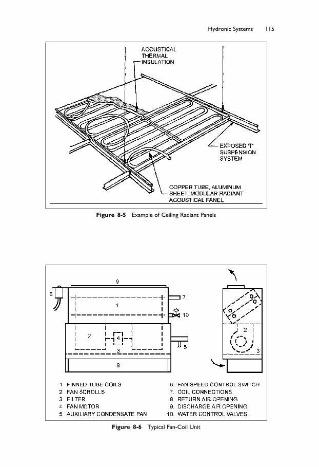
Elsevier UK Ch08-P373998 3-11-2006 7:34a.m. Page:115 Trimsize:6.5×9.5inches
Basal Font:Palatino Margins:Top:40pt Gutter:55pt Font Size:10/11 Text Width:29pc Depth:51 Lines
Hydronic Systems 115
Figure 8-5 Example of Ceiling Radiant Panels
Figure 8-6 Typical Fan-Coil Unit

Elsevier UK Ch08-P373998 3-11-2006 7:34a.m. Page:116 Trimsize:6.5×9.5inches
Basal Font:Palatino Margins:Top:40pt Gutter:55pt Font Size:10/11 Text Width:29pc Depth:51 Lines
116 Fundamentals of HVAC
as entrances and corridors, where temperature control is not critical, and tem-perature differential is large. Generally, in occupied spaces, a room thermostatshould be used to control the unit, to provide more accurate control.
Some units are provided with two or three speed controls for the fan, allow-ing adjustment in output of heat and generated noise. Many designers willchoose a unit that is designed to run at middle speed, to minimize the noisefrom the unit. Another way to minimize noise from the unit is to mount theunit in the ceiling space in the corridor and duct the air from the unit intothe room.
Hot-water fan coils. These are an ideal method of providing heat to thehigh, sporadic, loads in entrances. In cold climates, if the outside door doesnot close, the unit can freeze, so it is wise to include a thermostat that preventsthe fan from running if the outflow water temperature drops below 50 �C.Fan-coils may be run on an outdoor-reset water system, but this limits theiroutput and keeps the fan running more than if a constant, say 30 �C, watertemperature is supplied to the unit.
Changeover system. The same fan coil can be used for heating or for cooling,but with chilled water instead of hot water. This is called a changeover system.If a coil is used for cooling, it can become wet, due to condensation, andso it requires a condensate drain. The drain requires a slope of 10 mm permeter, to ensure that the condensate does not form a stagnant pool in thecondensate pan. Failure to provide an adequate slope can result in mold growthand consequent indoor air quality, IAQ, problems. For ceiling-mounted units,providing an adequate slope for the drain can be a real challenge.
If the coil is designed to run dry, with no condensation, then a filter is notabsolutely necessary. However, if the coil may run wet, it must be protectedwith a filter with efficiency minimum efficiency reporting value (MERV) ofnot less than 6 when rated in accordance with ANSI/ASHRAE Standard 52.2,to minimize lint and dust buildup on the coil. Both the filter and the drainrequire regular maintenance and therefore access to the unit must be available.
Timing is the challenge of changeover systems: when to change over fromheating to cooling and vice versa. For manual changeover systems, the springand fall can create real headaches for the operator. The system needs to beheating at night but cooling for the afternoon. The question for the operator is“What time should the change occur?” The challenge can be reduced if thereis a ventilation system with temperature control. When it is cool outside, theventilation air is supplied cool, thereby providing some cooling. When it iswarm outside, the ventilation air is supplied warm and that will provide alittle heating.
Generally, the operator will choose a day and change the system over,so that the spaces are either excessively warm in the afternoon or cool inthe morning. The advent of computerized controls has enabled designers toinclude sophisticated automatic programs that deal with the changeover issuefar more effectively than through manual operation.
Four-Pipe system: As an alternative design to a changeover system, the unitcan include two coils, heating and cooling, each with its own water circuit.This is called a four-pipe system, since there are a total of four pipes servingthe two coils. This system is more expensive to install but it is a more efficientsystem that completely avoids the problem of timing for change over fromheating to cooling.
The four-pipe fan-coil system is ideal for places like hotels, where roomsmay be unoccupied for long periods. The temperature can be allowed to drift
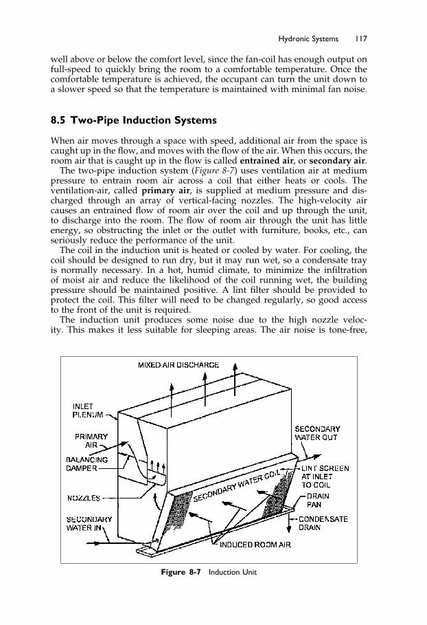
Elsevier UK Ch08-P373998 3-11-2006 7:34a.m. Page:117 Trimsize:6.5×9.5inches
Basal Font:Palatino Margins:Top:40pt Gutter:55pt Font Size:10/11 Text Width:29pc Depth:51 Lines
Hydronic Systems 117
well above or below the comfort level, since the fan-coil has enough output onfull-speed to quickly bring the room to a comfortable temperature. Once thecomfortable temperature is achieved, the occupant can turn the unit down toa slower speed so that the temperature is maintained with minimal fan noise.
8.5 Two-Pipe Induction Systems
When air moves through a space with speed, additional air from the space iscaught up in the flow, and moves with the flow of the air. When this occurs, theroom air that is caught up in the flow is called entrained air, or secondary air.
The two-pipe induction system (Figure 8-7) uses ventilation air at mediumpressure to entrain room air across a coil that either heats or cools. Theventilation-air, called primary air, is supplied at medium pressure and dis-charged through an array of vertical-facing nozzles. The high-velocity aircauses an entrained flow of room air over the coil and up through the unit,to discharge into the room. The flow of room air through the unit has littleenergy, so obstructing the inlet or the outlet with furniture, books, etc., canseriously reduce the performance of the unit.
The coil in the induction unit is heated or cooled by water. For cooling, thecoil should be designed to run dry, but it may run wet, so a condensate trayis normally necessary. In a hot, humid climate, to minimize the infiltrationof moist air and reduce the likelihood of the coil running wet, the buildingpressure should be maintained positive. A lint filter should be provided toprotect the coil. This filter will need to be changed regularly, so good accessto the front of the unit is required.
The induction unit produces some noise due to the high nozzle veloc-ity. This makes it less suitable for sleeping areas. The air noise is tone-free,
Figure 8-7 Induction Unit

Elsevier UK Ch08-P373998 3-11-2006 7:34a.m. Page:118 Trimsize:6.5×9.5inches
Basal Font:Palatino Margins:Top:40pt Gutter:55pt Font Size:10/11 Text Width:29pc Depth:51 Lines
118 Fundamentals of HVAC
though, and thus not annoying in most occupied spaces if silence is not aprerequisite.
The units are typically installed under a window, and when the air system isturned off the unit will provide some heat by natural convection, if hot wateris flowing through the coil.
8.6 Water Source Heat Pumps
Water source heat pumps are reversible refrigeration units. The refrigerationcircuit is the one we considered in Chapter 6, Figure 6-6 except that one coil iswater cooled/heated instead of air cooled/heated. The heat pump can eithertransfer heat from water into the zone or extract heat from the zone and rejectit into water. This ability finds two particular uses in building air conditioning:
The use of heat from the groundThe transfer of heat around a building.
The use of heat from the ground
There is a steady flow of heat from the core of the earth to the surface. As aresult, a few meters below the surface, the ground temperature remains fairlysteady. In cool climates, well below the frost line, this ground heat temperaturemay be only 5 �C, but in the southern United States it reaches 21 �C. Thisconstant temperature can be utilized in two ways. Where there is groundwateravailable, two, properly distanced, wells can be dug and the water pumpedup and through a heat pump. The heat pump can cool the water and heat thebuilding or, in reverse, heat the water and cool the building.
Where the water is too corrosive to use, or not available, water filled coils ofplastic pipe can be laid in the ground in horizontal or vertical arrays to absorbheat from, or dissipate heat into, the ground. This use of heat from the groundby a heat pump is commonly called a “ground-source heat pump.”
The ground-source heat pump provides relatively economical heating orcooling using electricity. The ground-source heat pump has a much highercooling efficiency than an air-cooler air-conditioning unit, making it veryattractive in areas where the summer electricity price is very high or supplycapacity is limited. In places where other fuels for heating are expensive, theground-source heat pump can be very attractive.
The transfer of heat around a building
The second use of heat pumps in building air conditioning is the water loopheat pump system. Here each zone is provided with one or more, heat pumps,connected to a water pipe loop around the building, see Figure 8-8. The wateris circulated at 15 �C to 33 �C and the pipe is normally not insulated. Eachzone heat pump uses the water to provide heating or cooling as required bythat zone.
As you can see in Figure 8-8, there is a boiler to provide heating and acooling tower to reject heat when the building has a net need for heating orcooling. The boiler, or tower, is used when required to maintain the circulationwater within the set temperature limits. The system provides local heatingor cooling at any time and each heat pump can be scheduled and controlledindependently.

Elsevier UK Ch08-P373998 3-11-2006 7:34a.m. Page:119 Trimsize:6.5×9.5inches
Basal Font:Palatino Margins:Top:40pt Gutter:55pt Font Size:10/11 Text Width:29pc Depth:51 Lines
Hydronic Systems 119
Figure 8-8 Heat Recovery System Using Water-to-Air Heat Pumps in a Closed Loop
The question is: “why would anyone design a system that required so muchequipment in a building?”
• In many buildings there are significant interior spaces that always requirecooling, due to the heat from occupants, lighting, and equipment. Thisheat is put into the water loop and can then be used in exterior zones forheating.
• In addition, there are often times when the solar heat gain on the south sideof a building requires zone cooling when the sun shines, while the north sideof the building still requires heating.

Elsevier UK Ch08-P373998 3-11-2006 7:34a.m. Page:120 Trimsize:6.5×9.5inches
Basal Font:Palatino Margins:Top:40pt Gutter:55pt Font Size:10/11 Text Width:29pc Depth:51 Lines
120 Fundamentals of HVAC
• Lastly there are buildings with significant heat generation equipment, suchas computer rooms, server racks, and telephone equipment, where thewaste heat from these operations can be used to heat the rest of thebuilding.
The heat pump units require regular filter changes to ensure that airflow ismaintained, since they each include a direct expansion refrigeration circuit. Inaddition, the water circuiting must be designed to maintain a constant flowthrough the operating units, even when other units are removed for repair.This issue will come up again when we are discussing water piping in the nextchapter, Chapter 9.
These closed loop systems are very effective in multiuse buildings, buildingswith substantial core areas and heating loads, and buildings where occupancyis variable in both time and quantity. Examples include offices, hotels, com-mercial, colleges, and laboratories.
The Next Step
Having considered a variety of hydronic systems in this chapter we will go onin Chapter 9 to consider the pumping, piping, balancing and control of watersystems.
Summary
This chapter has covered the more common hydronic systems used in air-conditioning buildings.
8.2 Natural Convection and Low Temperature Radiation HeatingSystems
The very simplest water heating systems consist of pipes with hot water flow-ing through them. The output from a bare pipe is generally too low to beeffective, so an extended surface is used to dissipate more heat. The radiatoremits heat by both radiation and convection. These water heaters can all becontrolled by varying the water flow or by varying the water supply temper-ature.
These hydronic heating systems do not provide any ventilation air fromoutside. When water systems are in use, ventilation requirements can be metby opening windows, window air conditioners, or separate ventilation systemswith optional cooling.
8.3 Panel Heating and Cooling
Radiant floors use the floor surface for heating. Ceilings can also be used forheating and/or cooling. The system has the advantage of taking up no flooror wall space and it collects no more dirt than a normal ceiling.
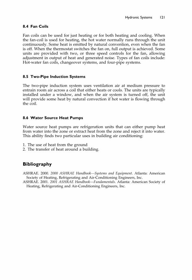
Elsevier UK Ch08-P373998 3-11-2006 7:34a.m. Page:121 Trimsize:6.5×9.5inches
Basal Font:Palatino Margins:Top:40pt Gutter:55pt Font Size:10/11 Text Width:29pc Depth:51 Lines
Hydronic Systems 121
8.4 Fan Coils
Fan coils can be used for just heating or for both heating and cooling. Whenthe fan-coil is used for heating, the hot water normally runs through the unitcontinuously. Some heat is emitted by natural convention, even when the fanis off. When the thermostat switches the fan on, full output is achieved. Someunits are provided with two, or three speed controls for the fan, allowingadjustment in output of heat and generated noise. Types of fan coils include:Hot-water fan coils, changeover systems, and four-pipe systems.
8.5 Two-Pipe Induction Systems
The two-pipe induction system uses ventilation air at medium pressure toentrain room air across a coil that either heats or cools. The units are typicallyinstalled under a window, and when the air system is turned off, the unitwill provide some heat by natural convection if hot water is flowing throughthe coil.
8.6 Water Source Heat Pumps
Water source heat pumps are refrigeration units that can either pump heatfrom water into the zone or extract heat from the zone and reject it into water.This ability finds two particular uses in building air conditioning:
1. The use of heat from the ground2. The transfer of heat around a building.
Bibliography
ASHRAE. 2000. 2000 ASHRAE Handbook—Systems and Equipment. Atlanta: AmericanSociety of Heating, Refrigerating and Air-Conditioning Engineers, Inc.
ASHRAE. 2001. 2001 ASHRAE Handbook—Fundamentals. Atlanta: American Society ofHeating, Refrigerating and Air-Conditioning Engineers, Inc.

Elsevier UK Ch09-P373998 3-11-2006 7:37a.m. Page:122 Trimsize:6.5×9.5inches
Basal Font:Palatino Margins:Top:40pt Gutter:55pt Font Size:10/11 Text Width:29pc Depth:51 Lines
Chapter 9
Hydronic System Architecture
Contents of Chapter 9
InstructionsObjectives of Chapter 99.1 Introduction9.2 Steam Systems9.3 Water Systems9.4 Hot Water Systems9.5 Chilled Water Systems9.6 Condenser WaterThe Next StepSummaryBibliography
Instructions
Read the material of Chapter 9. Re-read the parts of the chapter that areemphasized in the summary and memorize important definitions.
Objectives of Chapter 9
Chapter 9 introduces you to the various hydronic distribution systems andsome of their characteristics. Because this chapter is in a fundamentals course,we will not be developing detailed design information. For detailed informa-tion about water systems, you can take the ASHRAE Course, Fundamentals ofWater Systems.1
When you have completed this chapter, you should be familiar with:
Steam systems: The general operation and some of the advantages anddisadvantages of steam distribution systems.
Hot water heating systems: The main piping-layout options, pumpingrequirements and characteristics
Chilled water systems: The popular piping arrangements and characteristicsOpen water systems: The behavior of a condenser, condenser requirements,
and cooling tower operation

Elsevier UK Ch09-P373998 3-11-2006 7:37a.m. Page:123 Trimsize:6.5×9.5inches
Basal Font:Palatino Margins:Top:40pt Gutter:55pt Font Size:10/11 Text Width:29pc Depth:51 Lines
Hydronic System Architecture 123
9.1 Introduction
In previous chapters, we have considered a variety of systems that need asource of heat or cooling to operate. Many of these systems use water or steamfor this source. This chapter will introduce you to the basic layout optionsfor heating and cooling piping arrangements that distribute water or steam,hydronic circuits. It will also provide a brief discussion of the differences intheir hydronic characteristics.
In each case, a flow of steam or water is distributed from either a central boileror a chiller, the refrigeration equipment used to produce chilled water, to thehydronic circuits. The hydronic circuits circulate the steam or water through thebuilding, where it loses or gains heat before returning to be re-heated or re-cooled.
The steam or water is treated with chemicals to inhibit corrosion and bacterialgrowth in the system.
9.2 Steam Systems
Steam results from boiling water. As the water boils, it takes up latent heatof vaporization and expands to about 1600 times its original volume at atmo-spheric pressure. Steam is a gas, and in a vessel it quickly expands to fill thespace available at a constant pressure throughout the vessel. In this case, therelevant space is the boiler(s) and the pipe that runs from the boiler and aroundthe building. The pipe rapidly fills with steam, and the pressure is virtuallythe same from end to end under no-flow conditions. As flow increases, thereis a pressure drop due to friction against the pipe wall and due to the energyneeded to produce flow.
When the steam gives up its latent heat of evaporation in an end-use device,such as a coil, fan coil, or radiator, it condenses back to water, and the wateris called “condensate.” This condensate is removed from the steam system bymeans of a “steam trap.” A steam trap is so-named because it traps the steamwhile allowing the condensate out of the higher-pressure steam system intothe lower-pressure condensate return pipe.
Traps are typically thermostatic or float operated (Figure 9-1).
Thermostatic Trap: In the thermostatic trap, a bellows is used to hold the trapexit closed when heated by steam. The bellows is filled with a fluid that boilsat just below the steam temperature. When the trap fills with air or condensate,the temperature drops and the bellows contract, letting the air or condensateflow out. As soon as the air or condensate is expelled and the trap fills withsteam, the heated bellows expands, trapping the steam.
Float and Thermostatic Trap: This versatile trap uses the much higher densityof condensate to lift a float to open the trap and release the large quantities ofcondensate produced under startup and high-load periods. When filling thesystem, large volumes of air must be vented. The thermostatic element workswell for this function. During operation at low loads, the float functions well todrain the slow accumulation of condensate. In most systems, the condensateis gravity-piped to a condensate collection tank, before being intermittentlypumped back to the boiler makeup tank. Due to the much smaller volume ofcondensate, the condensate return piping is smaller in diameter than the steamsupply pipe.
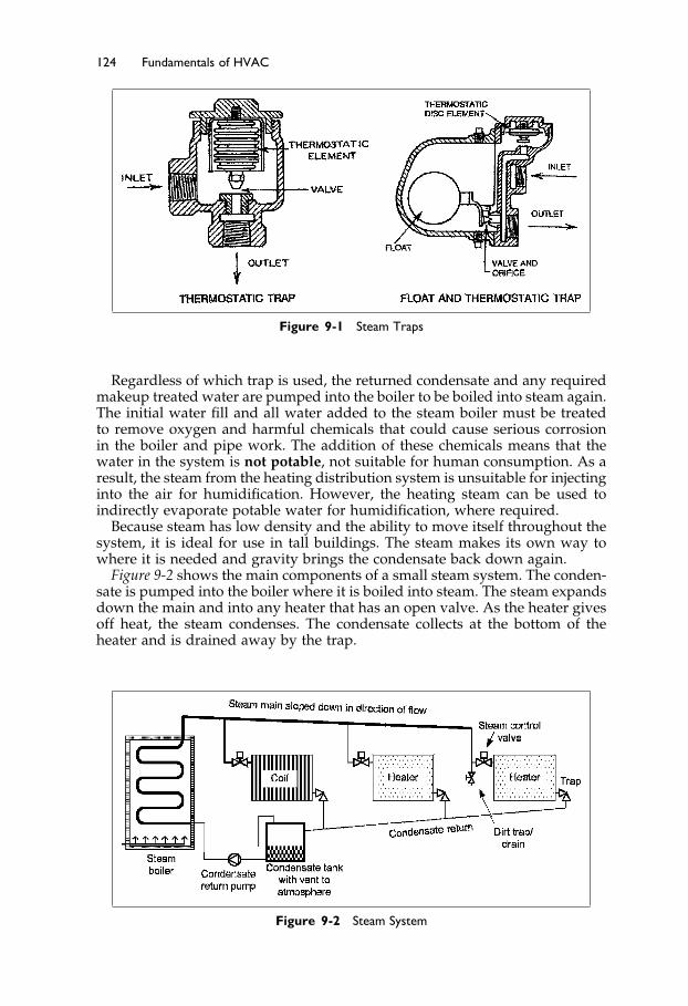
Elsevier UK Ch09-P373998 3-11-2006 7:37a.m. Page:124 Trimsize:6.5×9.5inches
Basal Font:Palatino Margins:Top:40pt Gutter:55pt Font Size:10/11 Text Width:29pc Depth:51 Lines
124 Fundamentals of HVAC
Figure 9-1 Steam Traps
Regardless of which trap is used, the returned condensate and any requiredmakeup treated water are pumped into the boiler to be boiled into steam again.The initial water fill and all water added to the steam boiler must be treatedto remove oxygen and harmful chemicals that could cause serious corrosionin the boiler and pipe work. The addition of these chemicals means that thewater in the system is not potable, not suitable for human consumption. As aresult, the steam from the heating distribution system is unsuitable for injectinginto the air for humidification. However, the heating steam can be used toindirectly evaporate potable water for humidification, where required.
Because steam has low density and the ability to move itself throughout thesystem, it is ideal for use in tall buildings. The steam makes its own way towhere it is needed and gravity brings the condensate back down again.
Figure 9-2 shows the main components of a small steam system. The conden-sate is pumped into the boiler where it is boiled into steam. The steam expandsdown the main and into any heater that has an open valve. As the heater givesoff heat, the steam condenses. The condensate collects at the bottom of theheater and is drained away by the trap.
Figure 9-2 Steam System

Elsevier UK Ch09-P373998 3-11-2006 7:37a.m. Page:125 Trimsize:6.5×9.5inches
Basal Font:Palatino Margins:Top:40pt Gutter:55pt Font Size:10/11 Text Width:29pc Depth:51 Lines
Hydronic System Architecture 125
Steam systems are divided into two categories: low-pressure systems andhigh-pressure systems. Low-pressure systems operate at no more than 100kilopascals, kPa, meaning no more than 100 kilopascals pressure higher thanthe local atmospheric pressure. High-pressure systems operate above 100 kPa.
Safety issues
In order to maintain the system pressure, the boiler output needs to becontinuously balanced with the load. Because steam has the capacity toexpand at high velocity in all directions, a poor boiler operation can cause anaccident.
The requirements for boiler operations on low-pressure systems are verymuch less stringent compared to high-pressure systems. Early in the twentiethcentury, there were numerous boiler explosions. As a result, the AmericanSociety of Mechanical Engineers wrote strict codes for the manufacture of steamboilers and associated piping and equipment. Those codes have drasticallyreduced the number of failures in North America.
The local pressure vessel regulations are relatively rigorously enforced inmost countries. The rules and regulations for both manufacture and opera-tion vary substantially in different countries, so having local information isalways a high priority when you are designing or operating a steam pressuresystem.
Steam systems need to be installed carefully, maintaining a downward slopeof 1 in 500 to avoid condensate collecting, called ponding, in the steam pipe. Ifcondensate ponds in the steam pipe and the steam flow increases significantly,a slug of condensate can be lifted and carried by the steam at very high velocityuntil it reaches a bend or other obstruction. The slug of water can attain ahigh momentum and may break the joint or valve. Not only can the pipe beruptured, but as soon as the pipe is ruptured, the steam is free to escape andcan easily burn, or kill, anyone in the area.
The advantages of steam are:
• Very high heat transfer.• No need for supply pumps.• Easy to add loads because the system adjusts to balance the loads.
These systems are much less popular than they used to be, but they are stillan attractive choice for distribution of large amounts of heat around numerousor high buildings.
9.3 Water Systems
Water systems are more commonly used for heating than are steam systems.The advantages of water over steam include the fact that water is safer andmore controllable than steam.
Water is safer because the system pressure is not determined by continuouslybalancing the boiler output with load, and because water does not have thecapacity to expand at high velocity in all directions.
Water is more controllable for heating since the water temperature can easilybe changed to modify the heat transfer.
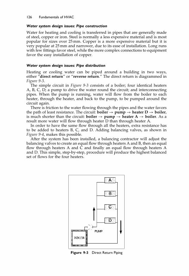
Elsevier UK Ch09-P373998 3-11-2006 7:37a.m. Page:126 Trimsize:6.5×9.5inches
Basal Font:Palatino Margins:Top:40pt Gutter:55pt Font Size:10/11 Text Width:29pc Depth:51 Lines
126 Fundamentals of HVAC
Water system design issues: Pipe construction
Water for heating and cooling is transferred in pipes that are generally madeof steel, copper or iron. Steel is normally a less expensive material and is mostpopular for sizes over 25 mm. Copper is a more expensive material but it isvery popular at 25 mm and narrower, due to its ease of installation. Long runswith few fittings favor steel, while the more complex connections to equipmentfavor the easy installation of copper.
Water system design issues: Pipe distribution
Heating or cooling water can be piped around a building in two ways,either “direct return” or “reverse return.” The direct return is diagrammed inFigure 9-3.
The simple circuit in Figure 9-3 consists of a boiler; four identical heatersA, B, C, D; a pump to drive the water round the circuit; and interconnectingpipes. When the pump is running, water will flow from the boiler to eachheater, through the heater, and back to the pump, to be pumped around thecircuit again.
There is friction to the water flowing through the pipes and the water favorsthe path of least resistance. The circuit: boiler → pump → heater D → boiler,is much shorter than the circuit: boiler → pump → heater A → boiler. As aresult more water will flow through heater D than through heater A.
In order to have the same flow through all the heaters, extra resistance hasto be added to heaters B, C, and D. Adding balancing valves, as shown inFigure 9-4, makes this possible.
After the system has been installed, a balancing contractor will adjust thebalancing valves to create an equal flow through heaters A and B, then an equalflow through heaters A and C and finally an equal flow through heaters Aand D. This simple, step-by-step, procedure will produce the highest balancedset of flows for the four heaters.
Figure 9-3 Direct Return Piping

Elsevier UK Ch09-P373998 3-11-2006 7:37a.m. Page:127 Trimsize:6.5×9.5inches
Basal Font:Palatino Margins:Top:40pt Gutter:55pt Font Size:10/11 Text Width:29pc Depth:51 Lines
Hydronic System Architecture 127
Figure 9-4 Direct Return Piping with Balancing Valves
The total flow may be more or less than design, but the flows will be equal.If the flow is more than required, it is possible, but difficult, to go back andrebalance to a specific lower flow.
In practice, a single balancing valve in the main loop, often between thepump and boiler, can be used to reduce the total flow. As the total flow isreduced, the flow in each heater will reduce in the same proportion. This circuitworks well, once it has been balanced. On most systems, a valve is installed oneach side of heaters so that the heater can be valved off and repaired withouthaving to shut down and drain the whole system.
Let us now imagine that one of the heaters failed and in the process ofremoving it, the balancing valve is closed. When the heater has been replaced,the question is “How much should the balancing valve be opened?” Did any-one take note of the valve position before it was moved? If not, the balancingvalve will likely be left fully open. The system may work satisfactorily withthe balance valve open, or, it may not. This problem of being dependent onbalancing valves can largely be overcome by using a different piping arrange-ment, the reverse return as shown in Figure 9-5. Here the pipe length for theflow loop boiler → pump → heater → boiler is the same for all heaters. Verifythis for yourself by tracing the water path through heater D and then the paththrough heater A. As a result, the flow will be the same in each heater; thepiping is self-balancing.
The reverse-return piping costs more due to the additional return length ofpipe. There are cases where the flow is critical, for example, direct expansionrefrigeration heat pumps. In this case, the additional cost of reverse returnpiping is worthwhile. The maintenance staff only needs to fully open the valvesto a unit to know it has full flow.
In circuits where exact balance is not critical, a system with direct returnand balancing valves is a good choice.
Having considered the two main piping arrangements let us now go on tothe flow of water and pumps.

Elsevier UK Ch09-P373998 3-11-2006 7:37a.m. Page:128 Trimsize:6.5×9.5inches
Basal Font:Palatino Margins:Top:40pt Gutter:55pt Font Size:10/11 Text Width:29pc Depth:51 Lines
128 Fundamentals of HVAC
Figure 9-5 Reverse Return Piping
Water system design issues: Flow
The resistance to water flow in pipes, called the head, is dependent on severalfactors including surface roughness, turbulence, and pipe size. When we designa system, we calculate the expected resistance for the design flow in eachpart of the circuit. The sum of the resistances gives the total resistance, orsystem head.
Under normal flow rates, the resistance rises by a factor of 1.85 to 1.9 as theflow rises (flow1�85 to flow1�9). Doubling the flow increases the resistance aboutthree and a half times.
The actual head loss in pipes is normally read from tables, to avoid repetitivecomplex calculations. Based on this table data and the knowledge that the headis proportional to flow1�85 we can plot the system curve of flow or capacity,versus head.
Pump manufacturers test their pumps to establish what flows the pumpgenerates at a range of heads. At a particular pump speed, measured in revo-lutions per minute, rpm, they will measure the head with no flow, and again atincreasing flows, or capacities. They can then plot the pump head against flowor capacity to produce a pump curve. A pump curve and calculated systemcurve are shown in Figure 9-6.
The pump curve in this figure shows a peak head of 45 meters with no flowthat gradually drops to about 33 meters at 7.4 liters per second, L/s, where itcrosses the calculated system curve. If the design calculations were correct, theoperating point for this pump will be at the intersection of the two curves.
In practice, the system curve often turns out to be higher or lower than thecalculated design. The effects of this, and remedies for it, are covered in theASHRAE course, Fundamentals of Water System Design.
The layout of piping in a building is very dependent on load locations andwhere pipe access is available. Figure 8-8, in the last chapter, showed a singleriser in the building with a reverse return loop around every floor. This workswell for heat pumps mounted in the ceiling, with the pipes running in theceiling.
Conversely, it often does not work very well for equipment, such as radi-ators, fan coils, and induction units, mounted near the floor at the perimeter

Elsevier UK Ch09-P373998 3-11-2006 7:37a.m. Page:129 Trimsize:6.5×9.5inches
Basal Font:Palatino Margins:Top:40pt Gutter:55pt Font Size:10/11 Text Width:29pc Depth:51 Lines
Hydronic System Architecture 129
Figure 9-6 System and Pump Curves
Figure 9-7 Multiple Risers
of the building. For these, multiple risers around the building may be a bettersolution, as shown in Figure 9-7.
Having introduced piping layouts and pumps let us go on to consider thethree main types of water circuits and some of their characteristics.
9.4 Hot Water Systems
Within buildings, hot water is the fluid that is most commonly used for heat-distribution. The amount of heat that is transferred is proportional to the tem-perature difference between supply and return. Maximizing the supply-returntemperature difference minimizes the water quantity and pipe size require-ments. Unfortunately, the economy of smaller water quantities with a high

Elsevier UK Ch09-P373998 3-11-2006 7:37a.m. Page:130 Trimsize:6.5×9.5inches
Basal Font:Palatino Margins:Top:40pt Gutter:55pt Font Size:10/11 Text Width:29pc Depth:51 Lines
130 Fundamentals of HVAC
temperature difference creates a need for larger, and more costly, heaters andheat exchangers. The design challenge is thus to find the best balance betweencost to install and cost to operate.
For general use, in buildings where the public may touch the pipes, thenormal operating supply temperature is 82 �C. In the past, return temperatureswere 70 �C, but temperatures of 65 �C, or even 60 �C, are now often used foroverall operating economy. Systems can also be designed to operate with an82 �C flow, except under peak load conditions. Peak load conditions hardlyever occur, but if they do, then the flow temperature can be raised as high as95 �C.
These systems can operate at very low pressure, since the only require-ment is that the pipes remain full. For working temperatures above 95 �C, atsea level, systems must be pressurized to avoid the possibility of the waterboiling.
As discussed in the previous chapter, radiant floors operate with a maximumsurface temperature of 29 �C. They need heating water at 50 �C or less, muchcooler than 82 �C. This can be achieved by mixing cool return water with the82 �C water to provide a supply to the floor at 50 �C or less. Alternatively, andwith greater fuel efficiency, they can be supplied from a condensing boiler orground source heat pump, both of which have a maximum flow temperatureof about 50 �C.
For distribution between buildings, higher temperatures—up to 230 �C—canbe used. The high temperature hot water is passed through a heat exchangerin each building to provide the, typically, 82 �C water for distribution aroundthe building and for heating domestic hot water.
Pipes should be insulated to avoid wasteful heat loss. Thus, pipes in theboiler room should be insulated, but pipes in a zone that is feeding a radiatormay not need to be insulated, since the heat loss just adds to the radiatoroutput. However, if a pipe presents an exposed surface that could cause aburn, insulation should be used.
Insulation thickness should take into account the temperature differencebetween the water and surroundings. Thus, thicker insulation should be usedon pipes that run outside a building than inside the building.
Energy Efficiency in Hot Water Systems
There are many ways to control and increase energy efficiency in the hotwater systems. The control method that we will discuss is the outdoor reset, acommon control strategy that takes advantage of the temperature differentialbetween the cold outside and the warm inside the building to adjust the heatoutput. Then we will consider pumps and the energy savings that we canobtain through reducing the flow in hot water systems.
The heat loss from a building in cold weather is proportional to the differ-ence between the temperature inside the building and the temperature outsidethe building. Similarly, the heat output from a convection heater is roughlyproportional to the difference between the space temperature and the heating-supply-water temperature. Outdoor reset makes combined use of these tworelationships by adjusting the heating-water temperature with changes in out-door temperature. With the correct schedule, the water flow remains constantand the heat output just balances the building heat loss.
This outdoor reset system has advantages, but it does mean that the heatingwater flow is 100% all through the heating season. This continuous full flowinvolves a significant pumping cost.

Elsevier UK Ch09-P373998 3-11-2006 7:37a.m. Page:131 Trimsize:6.5×9.5inches
Basal Font:Palatino Margins:Top:40pt Gutter:55pt Font Size:10/11 Text Width:29pc Depth:51 Lines
Hydronic System Architecture 131
In the last section we noted that the head is proportional to the flow1�85. Thepumping power is proportional to the head, times the flow. So, doubling theflow requires
2�21�85� = 7�2 times the power!
Here is an incentive to reduce flow. If, instead of modulating the watertemperature, it remained constant at, say 82 �C, and the flow was varied bythermostatic valves, the required flow would be much less than 100% mostof the time. In fact, since most heating systems are oversized, the flow wouldnever reach 100%. However, as soon as the flow varies, we need a method ofvarying the pump capacity.
In the following sections, we will consider two methods of varying pumpcapacity:
1. Varying pump speed2. Using pumps in parallel
Varying Pump Speed. Variable speed drives are now readily available andcan be used to adjust pump speed according to load. The pump curve remainsthe same shape, but shrinks as the speed reduces. Typical pump curves forvarious speeds are shown in Figure 9-8.
Figure 9-8 Variable Speed Pump Curves
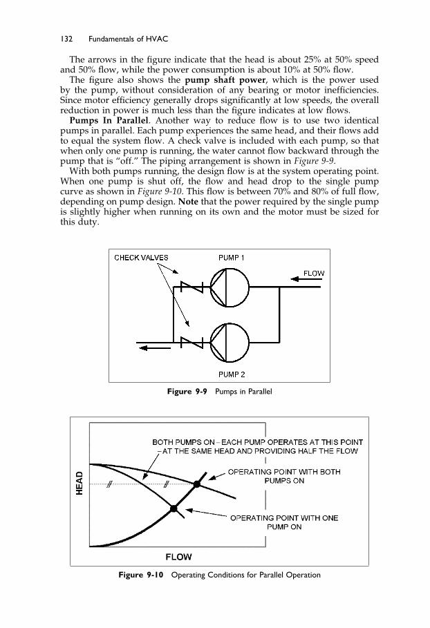
Elsevier UK Ch09-P373998 3-11-2006 7:37a.m. Page:132 Trimsize:6.5×9.5inches
Basal Font:Palatino Margins:Top:40pt Gutter:55pt Font Size:10/11 Text Width:29pc Depth:51 Lines
132 Fundamentals of HVAC
The arrows in the figure indicate that the head is about 25% at 50% speedand 50% flow, while the power consumption is about 10% at 50% flow.
The figure also shows the pump shaft power, which is the power usedby the pump, without consideration of any bearing or motor inefficiencies.Since motor efficiency generally drops significantly at low speeds, the overallreduction in power is much less than the figure indicates at low flows.
Pumps In Parallel. Another way to reduce flow is to use two identicalpumps in parallel. Each pump experiences the same head, and their flows addto equal the system flow. A check valve is included with each pump, so thatwhen only one pump is running, the water cannot flow backward through thepump that is “off.” The piping arrangement is shown in Figure 9-9.
With both pumps running, the design flow is at the system operating point.When one pump is shut off, the flow and head drop to the single pumpcurve as shown in Figure 9-10. This flow is between 70% and 80% of full flow,depending on pump design. Note that the power required by the single pumpis slightly higher when running on its own and the motor must be sized forthis duty.
Figure 9-9 Pumps in Parallel
Figure 9-10 Operating Conditions for Parallel Operation

Elsevier UK Ch09-P373998 3-11-2006 7:37a.m. Page:133 Trimsize:6.5×9.5inches
Basal Font:Palatino Margins:Top:40pt Gutter:55pt Font Size:10/11 Text Width:29pc Depth:51 Lines
Hydronic System Architecture 133
The use of parallel pumps for a heating system has two advantages: First, itproduces a substantial reduction in energy use for all the hours the system isusing only one pump; second, it provides automatic stand-by to at least 70%duty when one of the pumps fails.
9.5 Chilled Water Systems
Chilled water typically has a supply temperature of between 5�5 �C and 9 �C.Historically, the return temperature was often chosen to be 5 �C above theflow temperature. With the higher cost of fuel and the concern over energyusage, it is usually cost effective to design for a higher difference of 8 �C oreven 11 �C. The higher return temperatures require larger coils, and createchallenges when high dehumidification is required.
On the other hand, doubling the temperature difference halves the volumeflow, and, consequently, reduces the purchase cost of piping and pumps, aswell as substantially reducing ongoing pumping power costs.
With a flow temperature in the range 5�5 �C to 9 �C, the piping must beinsulated to reduce heat gain and avoid condensation. The insulation requiresa moisture barrier on the outside to prevent condensation on the pipe.
Chillers, the refrigeration equipment used to produce chilled water, mostlyuse a direct expansion evaporator. Therefore, the flow must be maintainedfairly constant to prevent the possibility of freezing the water. The chillerrequires constant flow but it would be both convenient and economical tohave variable flow to the loads. To achieve this, the chiller and loads can behydraulically “decoupled.” Decoupled, in this context, means that the flowsin the chiller circuit do not influence flows in the load circuit. Conversely,changes in the flows in the load circuit do not affect the chiller circuit.
A diagram of two chillers and loads is shown in Figure 9-11. The two chillersare piped in parallel in their own independent pipe loop, shown bold inthe Figure. The chiller loop can run even if the distribution pumps are off.Similarly, the distribution loop can run with the chiller pumps off. The short
Figure 9-11 Chiller System with Decoupled Flows
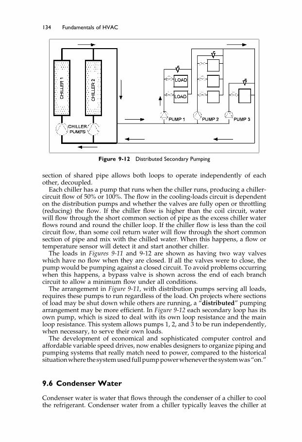
Elsevier UK Ch09-P373998 3-11-2006 7:37a.m. Page:134 Trimsize:6.5×9.5inches
Basal Font:Palatino Margins:Top:40pt Gutter:55pt Font Size:10/11 Text Width:29pc Depth:51 Lines
134 Fundamentals of HVAC
Figure 9-12 Distributed Secondary Pumping
section of shared pipe allows both loops to operate independently of eachother, decoupled.
Each chiller has a pump that runs when the chiller runs, producing a chiller-circuit flow of 50% or 100%. The flow in the cooling-loads circuit is dependenton the distribution pumps and whether the valves are fully open or throttling(reducing) the flow. If the chiller flow is higher than the coil circuit, waterwill flow through the short common section of pipe as the excess chiller waterflows round and round the chiller loop. If the chiller flow is less than the coilcircuit flow, than some coil return water will flow through the short commonsection of pipe and mix with the chilled water. When this happens, a flow ortemperature sensor will detect it and start another chiller.
The loads in Figures 9-11 and 9-12 are shown as having two way valveswhich have no flow when they are closed. If all the valves were to close, thepump would be pumping against a closed circuit. To avoid problems occurringwhen this happens, a bypass valve is shown across the end of each branchcircuit to allow a minimum flow under all conditions.
The arrangement in Figure 9-11, with distribution pumps serving all loads,requires these pumps to run regardless of the load. On projects where sectionsof load may be shut down while others are running, a “distributed” pumpingarrangement may be more efficient. In Figure 9-12 each secondary loop has itsown pump, which is sized to deal with its own loop resistance and the mainloop resistance. This system allows pumps 1, 2, and 3 to be run independently,when necessary, to serve their own loads.
The development of economical and sophisticated computer control andaffordable variable speed drives, now enables designers to organize piping andpumping systems that really match need to power, compared to the historicalsituationwhere thesystemusedfullpumppowerwhenever thesystemwas“on.”
9.6 Condenser Water
Condenser water is water that flows through the condenser of a chiller to coolthe refrigerant. Condenser water from a chiller typically leaves the chiller at
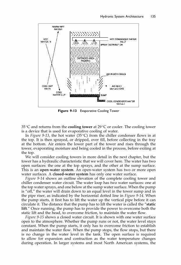
Elsevier UK Ch09-P373998 3-11-2006 7:37a.m. Page:135 Trimsize:6.5×9.5inches
Basal Font:Palatino Margins:Top:40pt Gutter:55pt Font Size:10/11 Text Width:29pc Depth:51 Lines
Hydronic System Architecture 135
Figure 9-13 Evaporative Cooling Tower
35 �C and returns from the cooling tower at 29 �C or cooler. The cooling toweris a device that is used for evaporative cooling of water.
In Figure 9-13, the hot water �35 �C� from the chiller condenser flows in atthe top. It is then sprayed, or dripped, over fill, before collecting in the trayat the bottom. Air enters the lower part of the tower and rises through thetower, evaporating moisture and being cooled in the process, before exiting atthe top.
We will consider cooling towers in more detail in the next chapter, but thetower has a hydraulic characteristic that we will cover here. The water has twoopen surfaces: the one at the top sprays, and the other at the sump surface.This is an open-water system. An open-water system has two or more openwater surfaces. A closed-water system has only one water surface.
Figure 9-14 shows an outline elevation of the complete cooling tower andchiller condenser water circuit. The water loop has two water surfaces: one atthe top water sprays, and one below at the sump water surface. When the pumpis “off,” the water will drain down to an equal level in the tower sump and inthe pipe riser, as indicated by the horizontal dotted line in Figure 9-14. Whenthe pump starts, it first has to lift the water up the vertical pipe before it cancirculate it. The distance that the pump has to lift the water is called the “staticlift.” Once running, the pump has to provide the power to overcome both thestatic lift and the head, to overcome friction, to maintain the water flow.
Figure 9-15 shows a closed water circuit. It is shown with one water surfaceopen to the atmosphere. Whether the pump runs or not, the water level staysconstant. When the pump starts, it only has to overcome friction to establishand maintain the water flow. When the pump stops, the flow stops, but thereis no change in the water level in the tank. The open surface is requiredto allow for expansion and contraction as the water temperature changesduring operation. In larger systems and most North American systems, the

Elsevier UK Ch09-P373998 3-11-2006 7:37a.m. Page:136 Trimsize:6.5×9.5inches
Basal Font:Palatino Margins:Top:40pt Gutter:55pt Font Size:10/11 Text Width:29pc Depth:51 Lines
136 Fundamentals of HVAC
Figure 9-14 Open Water Circuit
Figure 9-15 Closed Water Circuit
one open water surface is in a closed tank of compressed air rather than opento atmosphere, as is common in other parts of the world.
The cooling tower provides maintenance challenges. It contains warm waterand dust, so it easily supports the multiplication of the potentially lethalbacteria, legionella.
We will return to cooling towers, their design, interconnection, and operationwhen we discus central plants in the next chapter.

Elsevier UK Ch09-P373998 3-11-2006 7:37a.m. Page:137 Trimsize:6.5×9.5inches
Basal Font:Palatino Margins:Top:40pt Gutter:55pt Font Size:10/11 Text Width:29pc Depth:51 Lines
Hydronic System Architecture 137
The Next Step
This chapter has covered hydronics architecture, specifically the piping systemsfor steam, hot water, chilled water, and condenser water. In Chapter 10 weare going to consider the central plant boilers, chillers, and cooling towers thatproduce the sources of steam and water at various temperatures.
Summary
In this chapter, we covered hydronics systems, systems involving the flow ofsteam or water to transfer heat or cooling from one place to another.
9.2 Steam Systems
Principal ideas of this section include: how steam is used; its behavior as agas and how it condenses as it gives up its latent heat; how the resultantcondensate is drained out of the steam pipes by traps and then returned to theboiler, to be boiled into steam again.
9.3 Water Systems
In this section we described water systems and the economical direct arrange-ment and the more costly, but largely self-balancing, reverse-return pipingarrangement. Once a system has been designed, the design flow and head areknown and can be plotted on the same graph as the pump curve, to find theexpected operating condition.
9.4 Hot Water Systems
From general water systems, we moved into hot water systems. The use andenergy savings of variable speed pumps was introduced. This was followedby a discussion of how two pumps in parallel can be used to provide reducedenergy consumption for most of the heating season, as well as substantial,automatically-available, stand-by capacity should a pump fail.
9.5 Chilled Water Systems
Because chilled water systems need constant water flow through the chillerevaporator, the economies of variable flow can be achieved through decoupledand distributed piping arrangements.
9.6 Condenser Water
Cooling towers were described as well as the difference between open andclosed water systems. The hot water and chilled water circuits are normally

Elsevier UK Ch09-P373998 3-11-2006 7:37a.m. Page:138 Trimsize:6.5×9.5inches
Basal Font:Palatino Margins:Top:40pt Gutter:55pt Font Size:10/11 Text Width:29pc Depth:51 Lines
138 Fundamentals of HVAC
closed systems, but the cooling tower is an open system. The open system hasa modified design requirement, since the pump must not only overcome thefriction, head, to flow around the circuit, but must also provide lift to raise thewater from the balance point to the highest point in the system.
Bibliography
ASHRAE. 1998. Fundamentals of Water System Design. Atlanta: American Society ofHeating, Refrigerating and Air-Conditioning Engineers, Inc.
ASHRAE. 2004. 2004 ASHRAE Handbook—Systems and Equipment. Atlanta: AmericanSociety of Heating, Refrigerating and Air-Conditioning Engineers, Inc.
ASHRAE. 2001. 2001 ASHRAE Handbook—Fundamentals. Atlanta: American Society ofHeating, Refrigerating and Air-Conditioning Engineers, Inc.

Elsevier UK Ch10-P373998 3-11-2006 7:38a.m. Page:139 Trimsize:6.5×9.5inches
Basal Font:Palatino Margins:Top:40pt Gutter:55pt Font Size:10/11 Text Width:29pc Depth:51 Lines
Chapter 10
Central Plants
Contents of Chapter 10
InstructionsObjectives of Chapter 1010.1 Introduction10.2 Central Plant versus Local Plant in a Building10.3 Boilers10.4 Chillers10.5 Cooling TowersThe Next StepSummaryBibliography
Instructions
Read the material of Chapter 10. Re-read the parts of the chapter that areemphasized in the summary and memorize important definitions.
Objectives of Chapter 10
In the last chapters we have discussed various air-conditioning systems andthe fact that heating and cooling can be provided from a central plant bymeans of hot water, steam, and chilled water. In this chapter we will considercentral plants. We will start with some general considerations about whatthey produce, their advantages, and their disadvantages. After studying thechapter, you should be able to:
Discuss some advantages and disadvantages of central plants.Identify the main types of boiler and sketch a twin boiler circuit.Describe the operation of chillers, and be able to sketch a dual chiller instal-
lation with primary only, and primary-secondary chilled water circuits.Understand the operation of cooling towers, what affects their perfor-
mance, and what regular maintenance is required for safe and reliableoperation.
Elsevier UK Ch10-P373998 3-11-2006 7:38a.m. Page:140 Trimsize:6.5×9.5inches
Basal Font:Palatino Margins:Top:40pt Gutter:55pt Font Size:10/11 Text Width:29pc Depth:51 Lines
140 Fundamentals of HVAC
10.1 Introduction
For this course, central plants include boilers, producing steam or hot water,and chillers, producing chilled water. These pieces of equipment can satisfythe heating and cooling requirements for a complete building. In a centralplant, the boilers and chillers are located in a single space in the building, andtheir output is piped to all the various air-conditioning units and systems inthe building. They are used in all types of larger buildings. Their initial costis often higher than packaged units and they require installation floor areaas well as space through the buildings for distribution pipes. Central plantsgenerally require less maintenance than numerous smaller package systemsand the equipment usually has a longer life.
This central plant concept can be extended to provide heating and coolingto many buildings on a campus or part of a town. The equipment for theselarger systems is often housed in a separate building which reduces, or avoids,noise and safety issues.
We will be discussing some of the advantages and disadvantages of centralplants and then we will go on to consider the main items of equipment foundin central plants: boilers, chillers, and cooling towers.
Boilers are pressure vessels and their installation and operation are strictlyprescribed by codes. Their general construction, operation, and main safetyfeatures will be discussed.
Chillers come in a huge range of sizes and types and we will briefly intro-duce them. We will discuss their particular requirements for chilled waterpiping and specialized control.
The job of the chiller is to remove heat from the water and reject it to thecondenser. The condensers are often water-cooled. The cooling water is called“condenser water.” The condenser water flows to a cooling tower, where itis cooled before it returns to the chiller to be heated once again. This will bediscussed in detail in Section 10.4.
Cooling towers are devices used to cool water by evaporation. Water issprayed or dripped over material with a large surface area, while outdoor airis drawn through. Some water evaporates, cooling the bulk of the water beforeit returns to the chiller.
10.2 Central Plant versus Local Plant in a Building
There is no rule about when a central plant is the right answer or whendistributed packages or systems should be used. Circumstances differ fromproject to project, and location to location. The good designer will assess eachproject on the merits of that situation and involve the client in making themost suitable choice for the project.
In this section we are going to consider, in a general way, some of thetechnical issues that can influence the choice. We are not going to considerthe internal politics that can have major influences and costs in time andmoney. In addition to politics, the availability of money for installation versusoperating costs can have a major impact on system choices. For minimuminstallation-cost, the package approach usually wins.
Here are some true statements in favor of central plants. Read them. Canyou think of a reason why each one of them might, in some circumstances, bewrong, or irrelevant? Write down your suggested reason.

Elsevier UK Ch10-P373998 3-11-2006 7:38a.m. Page:141 Trimsize:6.5×9.5inches
Basal Font:Palatino Margins:Top:40pt Gutter:55pt Font Size:10/11 Text Width:29pc Depth:51 Lines
Central Plants 141
“It is easy to have someone watching the plant if it is all in one place.”“The large central plant equipment is always much more efficient than small
local plant.”“The endless cost of local plant replacement makes it uneconomic compared to a
main central plant.”
As you know, technology is rapidly changing, and you should think aboutwhether categorical statements or “rules-of-thumb” are correct or relevant inyour particular situation. You cannot go against the laws of physics, but everyday new ways of doing things are being developed.
Let us consider each of the above statements in turn.
“It is easy to have someone watching the plant if it is all in one place.”
This statement is true if visual inspection of the plant is useful. A hundredyears ago, the look and sound of the plant were the best, and only, indicatorsof performance. Operators “knew their plant” and almost intuitively knewwhen things needed attention. Now, in the 21st century, plant is much morecomplex and we have excellent monitoring equipment available at a reasonableprice. The information from those monitors can be instantly, and remotely,available. So instead of paying someone to physically watch the central plant,the building owner can pay someone to monitor the performance of, not justthe central plant, but all the plant, regardless of where it is located in thebuildings. Now, using the Internet, many buildings can be monitored fromanywhere in the world with fast and reliable Internet service.
The second statement, “The large central plant equipment is always more efficientthan small local plant,” is generally true but not always relevant. For example,an apartment building might have a large central boiler that provides both hotwater for heating, and domestic hot water. In winter this is an efficient system.However throughout the summer the boiler will be running sporadically atvery low load. It will take a considerable amount of energy to heat up theboiler before it starts to heat the domestic water, and this heat will dissipateto atmosphere before it is called on to heat the water again—very inefficient.The unit has a high efficiency at full load but when its efficiency is averagedover the year, “seasonal efficiency,” may be surprisingly low.
In this situation, it may be beneficial to install a series of small hot-waterheaters for the domestic hot water, although they are not as efficient as themain boiler at full load. Their advantage is that they only run when neededand have low standby losses.
The last statement “The endless cost of local plant replacement makes it uneco-nomic compared to a main central plant,” is also true in some cases, but definitelynot in other cases. In many organizations, replacement of smaller pieces ofequipment is paid for as part of the maintenance operations’ budget. On theother hand, major plant replacements are paid for out of a separate “capital”fund. From the point-of-view of the maintenance managers, small, local plantis an endless expense to their maintenance budget, while other budgets fundlarge, central-plant replacements from the capital account. When it comes tonew facilities, the maintenance managers in this situation are likely to be biasedagainst small, packaged-plant equipment, because its replacement costs willall fall on their maintenance budget.
Let us go back to the reasons you wrote down as to why these three state-ments about central plant might be wrong. Are you still comfortable with themand can you think of others?

Elsevier UK Ch10-P373998 3-11-2006 7:38a.m. Page:142 Trimsize:6.5×9.5inches
Basal Font:Palatino Margins:Top:40pt Gutter:55pt Font Size:10/11 Text Width:29pc Depth:51 Lines
142 Fundamentals of HVAC
This section has deliberately been encouraging you to think about thesome of the pros and cons of central plants. Now let us consider three otheradvantages.
1. “It is so much easier to maintain a high standard of operation and mainte-nance of a few large units in a single place, instead of lots of little packagesall over the site.”
Plant operators know that having complete information about the plant,all the tools in one place, space to work, and protection from the weather,all make central plant maintenance very attractive.
2. “Trying to optimize many package units is really difficult compared to thetwo identical chillers and boilers in our central plant.”
A few central pieces of equipment can be monitored relatively easily andadjusted by the maintenance staff. When there are many units all over thebuilding, it becomes difficult to remember which one is which and theirindividual quirks and characteristics.
3. “Heat recovery from central plant chillers and boilers is financiallyworthwhile.”
Heat recovery is the recovery of heat that would otherwise have goneto waste. For example, the chiller absorbs heat from the chilled water andrejects it through the condenser to atmosphere. In a hospital with sub-stantial hot water loads, some of this waste heat could be used to preheatthe domestic hot water and perhaps to heat the air-conditioning reheatcoils.
In a similar way, additional heat can be recovered from boiler flue gasesby means of a recuperator. This is a device consisting of water sprays ina corrosion resistant section of flue. The water heats to around 50 �C andis pumped through a water-to-water heat exchanger to provide water atabout 46 �C. This water can be used in an oversized coil for preheatingoutdoor air.
Both the heat-recovery from the chillers and recuperator-heat fromthe boilers are examples of the improved energy efficiency that isoften not economically feasible on the smaller distributed-packagedequipment.
10.3 Boilers
Boilers are pressure vessels used to produce steam or hot water. They aredifferent from furnaces, a term usually used to refer to air heaters of any size.Boilers come in a vast range of types and sizes.
The critical design factor is pressure. Boilers are fitted with safety valves thatrelease the steam or water if the pressure rises significantly above the designpressure. The safety-equipment requirement and staff-monitoring require-ments are far less stringent for low-pressure boilers, so there is a significantincentive to use low-pressure except where high pressure is needed, or moreeconomic.
A “low-pressure” steam boiler operates at a pressure of no more than 100kilopascals, 100 kPa, more than the local atmospheric pressure. This means100 kPa as measured by a gauge exposed to the local atmospheric pressure.

Elsevier UK Ch10-P373998 3-11-2006 7:38a.m. Page:143 Trimsize:6.5×9.5inches
Basal Font:Palatino Margins:Top:40pt Gutter:55pt Font Size:10/11 Text Width:29pc Depth:51 Lines
Central Plants 143
In comparison, “low-pressure” hot water boilers are allowed up to 1100 kPa.There is a good reason for the extreme difference in allowable pressure:
When a steam boiler fails, the effect can be catastrophic: as the steamexpands uncontrollably, it is like a bomb going off. In comparison, when ahot water system bursts, the hot water pours out, but there is no explosiveblast like there is with steam. For this reason, “low-pressure” hot waterboilers are allowed up to the higher pressure of 1100 kPa.
Boilers and system components are regulated by codes. These codes aregenerally written, and updated, by practitioners in their geographic area. Themain codes in North America are those issued by the American Society ofMechanical Engineers (ASME) Boiler and Pressure Vessel Code while the Euro-pean Community has their own, and in many areas, much less demandingset of codes. It is therefore critical that a designer or operator knows the localcode requirements, since their experience from one place may not be relevantin another jurisdiction.
Boiler Components
Boilers have two sections: the combustion section and the heat transfer section.The combustion section is the space in which the fuel-air mixture burns.
Figure 10-1 shows a commercial boiler with the combustion chamber at thebottom. In this boiler, the base is insulated, but the top and sides of the com-bustion chamber are heat transfer surfaces. The proportion of air significantlyinfluences the efficiency. If there is excess air, it is heated as it goes through theboiler, carrying heat with it up the chimney. Too little air will cause poor com-bustion, usually producing noxious combustions products and, in the extreme,
Figure 10-1 Three-Pass Commercial Water Tube Boiler

Elsevier UK Ch10-P373998 3-11-2006 7:38a.m. Page:144 Trimsize:6.5×9.5inches
Basal Font:Palatino Margins:Top:40pt Gutter:55pt Font Size:10/11 Text Width:29pc Depth:51 Lines
144 Fundamentals of HVAC
may cause extra expense by allowing unburnt fuel through the boiler and upthe chimney.
The second section of the boiler is the heat-transfer section. This sectioncomprises the two upper spaces in Figure 10-1, where the hot gases pass right-to-left and then left-to-right, before exiting to go up the flue. In large boilers,the heat transfer section will be fabricated of cast iron sections that are boltedtogether, or of welded steel plate and tubes. In smaller, particularly domestic,boilers, the heat-transfer section may be fabricated from copper, aluminum, orstainless steel sheet. Boilers can be designed for any fuel: electricity, gas, oil,or coal are the most usual. In this age of recycling and sustainability, there isalso an initiative to use urban and manufacturing waste as fuel.
In all boilers, there is a need to modulate, or adjust, the heat input. Gasand oil burners may be cycled “on” and “off.” The longer the “on” cycle, thegreater the heat input. With the “on-off” cycle, the water temperature or steamoutput will vary up and down, particularly at low loads. This may not matter,but the efficiency improves and cycling effect is much reduced by having aburner with “high-low-off” cycles.
On larger units, a modulating burner will usually be installed that can adjustthe output from 100% down to some minimum output. The burner modulationrange is called the “turn-down ratio,” which is the ratio between full “on”and the lowest continuous operation. A burner that can operate at anywherefrom 100% output down to 10% output has a 10:1 turn-down ratio. With amodulating burner, efficiency increases as the output drops. This increase inefficiency is due to the increase in the ratio of heat-exchanger surface-area toheat-input as the output, or firing rate, is reduced.
In a coal-fired boiler, the adjustment is achieved by altering the draft ofcombustion air through the grate. As the air supply increases, the fuel burnsfaster and hotter, increasing the boiler output.
In general, boiler efficiency drops as the mean temperature of the heatedfluid rises. As a result, a hot-water boiler will be more efficient heating waterfrom 65 �C to 75 �C (mean temperature 70 �C) than from 70 �C to 80 �C (meantemperature 75 �C). However, the cooler the mean temperature of the heatedfluid, the larger the heat-transfer surfaces must be. Here we have anotherexample of where the designer must consider trading the higher ongoing costsand use of fuel against initial equipment costs.
Because boiler operation is critical for the facility, it is often valuable to havea two-boiler system, so that there is always one available for maintenanceback up.
Figure 10-2 shows a hot water system with two boilers.
The boilers, which are connected in parallel so that one can be valved offand serviced or replaced while the other continues to operate.
Two pumps, so that pump failure does not prevent operation.A pressure tank which maintains system pressure and accommodates the
changes in water volume as the system is heated up from cold. Thepressure tank often has a membrane in it that separates the water fromthe air, to prevent absorption of oxygen from the air. If the water leveldrops too low, more water is pumped into the system; if the pressureneeds to be increased, more air is pumped into the top of the tank.
A spring-loaded safety valve, which is provided for each boiler. The valveis set to release at some pre-determined pressure. Then if, for example,the burner controls jammed at full fire, the hot water or steam wouldbe released, protecting the system from bursting.
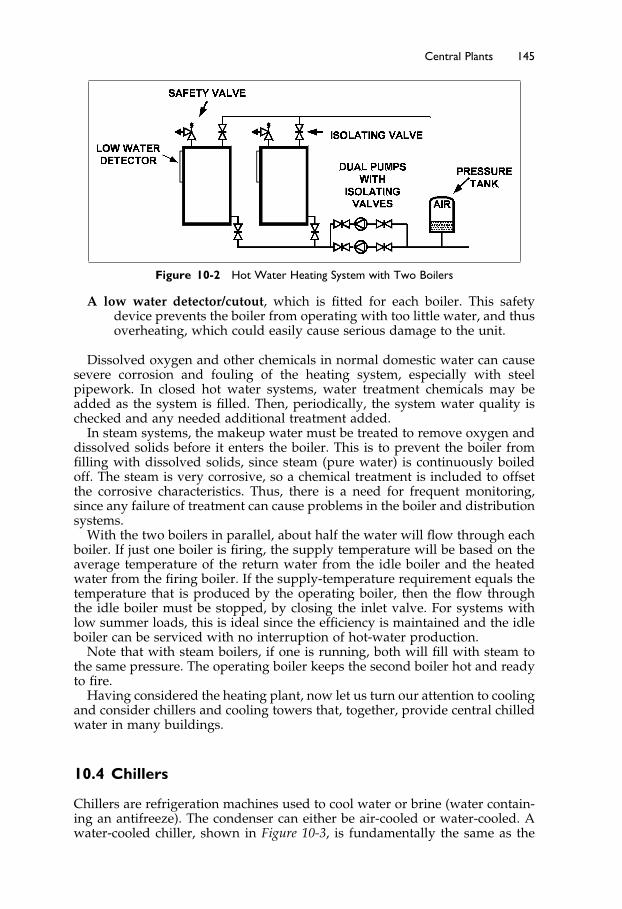
Elsevier UK Ch10-P373998 3-11-2006 7:38a.m. Page:145 Trimsize:6.5×9.5inches
Basal Font:Palatino Margins:Top:40pt Gutter:55pt Font Size:10/11 Text Width:29pc Depth:51 Lines
Central Plants 145
Figure 10-2 Hot Water Heating System with Two Boilers
A low water detector/cutout, which is fitted for each boiler. This safetydevice prevents the boiler from operating with too little water, and thusoverheating, which could easily cause serious damage to the unit.
Dissolved oxygen and other chemicals in normal domestic water can causesevere corrosion and fouling of the heating system, especially with steelpipework. In closed hot water systems, water treatment chemicals may beadded as the system is filled. Then, periodically, the system water quality ischecked and any needed additional treatment added.
In steam systems, the makeup water must be treated to remove oxygen anddissolved solids before it enters the boiler. This is to prevent the boiler fromfilling with dissolved solids, since steam (pure water) is continuously boiledoff. The steam is very corrosive, so a chemical treatment is included to offsetthe corrosive characteristics. Thus, there is a need for frequent monitoring,since any failure of treatment can cause problems in the boiler and distributionsystems.
With the two boilers in parallel, about half the water will flow through eachboiler. If just one boiler is firing, the supply temperature will be based on theaverage temperature of the return water from the idle boiler and the heatedwater from the firing boiler. If the supply-temperature requirement equals thetemperature that is produced by the operating boiler, then the flow throughthe idle boiler must be stopped, by closing the inlet valve. For systems withlow summer loads, this is ideal since the efficiency is maintained and the idleboiler can be serviced with no interruption of hot-water production.
Note that with steam boilers, if one is running, both will fill with steam tothe same pressure. The operating boiler keeps the second boiler hot and readyto fire.
Having considered the heating plant, now let us turn our attention to coolingand consider chillers and cooling towers that, together, provide central chilledwater in many buildings.
10.4 Chillers
Chillers are refrigeration machines used to cool water or brine (water contain-ing an antifreeze). The condenser can either be air-cooled or water-cooled. Awater-cooled chiller, shown in Figure 10-3, is fundamentally the same as the

Elsevier UK Ch10-P373998 3-11-2006 7:38a.m. Page:146 Trimsize:6.5×9.5inches
Basal Font:Palatino Margins:Top:40pt Gutter:55pt Font Size:10/11 Text Width:29pc Depth:51 Lines
146 Fundamentals of HVAC
Figure 10-3 Water Chiller with Water Cooled Condenser
basic refrigeration circuit you were introduced to in Figure 10-3, Chapter 6,Section 6.3, except that, instead of the evaporator and condenser being air-cooled, they are now water-cooled.
As you can see in the drawing, there are two flows of water, labeled thechilled water and the condenser water. The water that flows through theevaporator coil gives up heat, and becomes cooler. The cooled water is referredto as “chilled water.” The water that flows through the condenser, called the“condenser water,” becomes warmer and is piped away to a cooling tower tobe cooled before returning to the condenser to be warmed again.
The size of the cooling load determines the requirements for chiller capacity.This requirement can be met by one or more chillers. The standard measureof chiller capacity is the kilowatt, a heat absorption capacity of 1000 watts.The historical origin of this unit is from early days of refrigeration, whenice production was the main use. In 24 hours, 12,000 Btu per hour (3.517 kW)produces one ton of ice. Residential air-conditioners are typically two to tenkilowatts; central chillers, delivered as complete, preassembled packages fromthe factory, can be as large as 8500 kilowatts; and built-up units can go up to35000 kilowatts.
The main difference between chillers is the type of compressor:
• Smaller compressors are often reciprocating units, very much like an auto-mobile engine, with pistons compressing the refrigerant.
• Larger units may have screw or scroll compressors. These compressors arecalled “positive-displacement,” since they have an eccentric scroll or screwthat traps a quantity of refrigerant and squeezes it into a much smallervolume as the screw or scroll rotates.
• Finally, for 265 kW up to the largest machines, there is the centrifugal com-pressor. It has radial blades spinning at high speed that compress the refrig-erant.
The choice of compressors is influenced by efficiency at full and part load,ability to run at excess load, size, and other factors. At times of lower load, thecapacity of the reciprocating compressor can be reduced in steps by unloadingcylinders. The other types of machine can all have their capacity reduced,
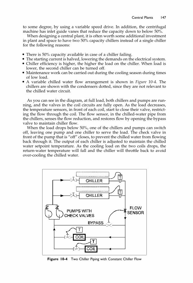
Elsevier UK Ch10-P373998 3-11-2006 7:38a.m. Page:147 Trimsize:6.5×9.5inches
Basal Font:Palatino Margins:Top:40pt Gutter:55pt Font Size:10/11 Text Width:29pc Depth:51 Lines
Central Plants 147
to some degree, by using a variable speed drive. In addition, the centrifugalmachine has inlet guide vanes that reduce the capacity down to below 50%.
When designing a central plant, it is often worth some additional investmentin plant and space to have two 50% capacity chillers instead of a single chillerfor the following reasons:
• There is 50% capacity available in case of a chiller failing.• The starting current is halved, lowering the demands on the electrical system.• Chiller efficiency is higher, the higher the load on the chiller. When load is
lower, the second chiller can be turned off.• Maintenance work can be carried out during the cooling season during times
of low load.• A variable chilled water flow arrangement is shown in Figure 10-4. The
chillers are shown with the condensers dotted, since they are not relevant tothe chilled water circuit.
As you can see in the diagram, at full load, both chillers and pumps are run-ning, and the valves in the coil circuits are fully open. As the load decreases,the temperature sensors, in front of each coil, start to close their valve, restrict-ing the flow through the coil. The flow sensor, in the chilled-water pipe fromthe chillers, senses the flow reduction, and restores flow by opening the bypassvalve to maintain chiller flow.
When the load drops below 50%, one of the chillers and pumps can switchoff, leaving one pump and one chiller to serve the load. The check valve infront of the pump that is “off” closes, to prevent the chilled water from flowingback through it. The output of each chiller is adjusted to maintain the chilledwater setpoint temperature. As the cooling load on the two coils drops, thereturn-water temperature will fall and the chiller will throttle back to avoidover-cooling the chilled water.
Figure 10-4 Two Chiller Piping with Constant Chiller Flow
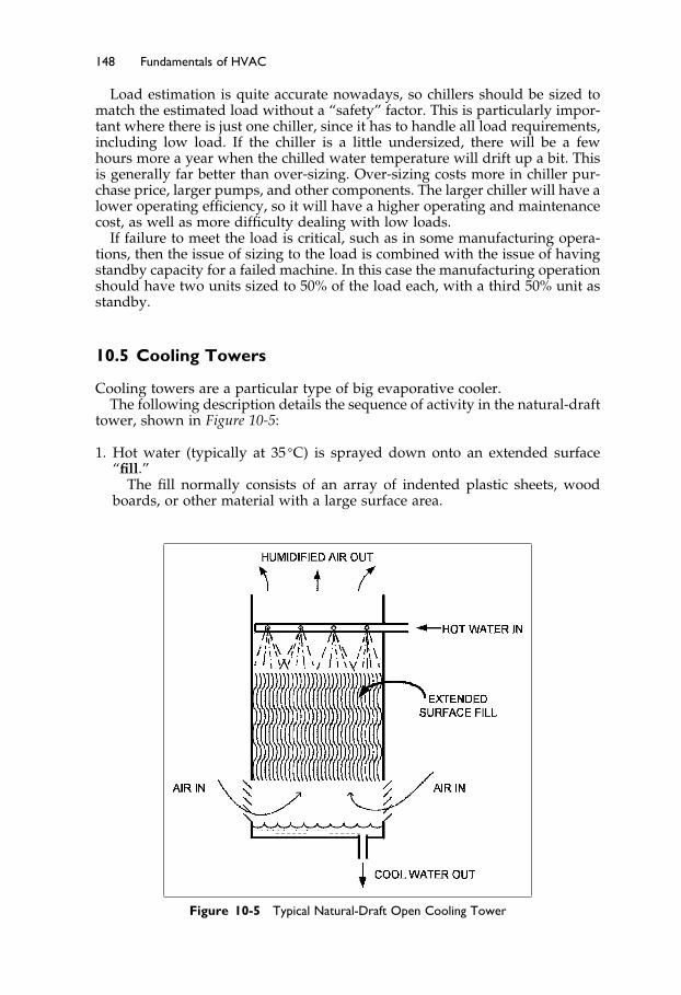
Elsevier UK Ch10-P373998 3-11-2006 7:38a.m. Page:148 Trimsize:6.5×9.5inches
Basal Font:Palatino Margins:Top:40pt Gutter:55pt Font Size:10/11 Text Width:29pc Depth:51 Lines
148 Fundamentals of HVAC
Load estimation is quite accurate nowadays, so chillers should be sized tomatch the estimated load without a “safety” factor. This is particularly impor-tant where there is just one chiller, since it has to handle all load requirements,including low load. If the chiller is a little undersized, there will be a fewhours more a year when the chilled water temperature will drift up a bit. Thisis generally far better than over-sizing. Over-sizing costs more in chiller pur-chase price, larger pumps, and other components. The larger chiller will have alower operating efficiency, so it will have a higher operating and maintenancecost, as well as more difficulty dealing with low loads.
If failure to meet the load is critical, such as in some manufacturing opera-tions, then the issue of sizing to the load is combined with the issue of havingstandby capacity for a failed machine. In this case the manufacturing operationshould have two units sized to 50% of the load each, with a third 50% unit asstandby.
10.5 Cooling Towers
Cooling towers are a particular type of big evaporative cooler.The following description details the sequence of activity in the natural-draft
tower, shown in Figure 10-5:
1. Hot water (typically at 35 �C) is sprayed down onto an extended surface“fill.”
The fill normally consists of an array of indented plastic sheets, woodboards, or other material with a large surface area.
Figure 10-5 Typical Natural-Draft Open Cooling Tower
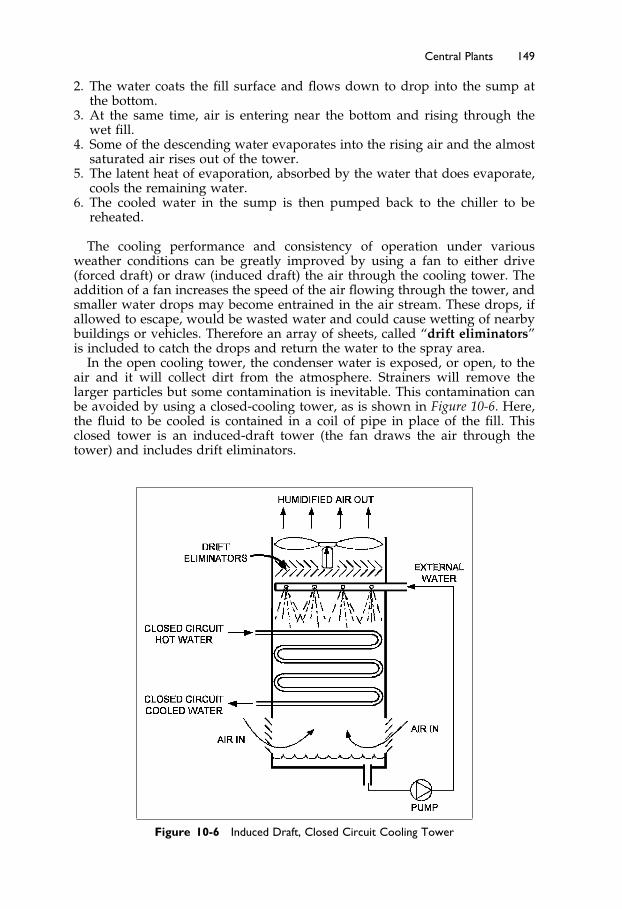
Elsevier UK Ch10-P373998 3-11-2006 7:38a.m. Page:149 Trimsize:6.5×9.5inches
Basal Font:Palatino Margins:Top:40pt Gutter:55pt Font Size:10/11 Text Width:29pc Depth:51 Lines
Central Plants 149
2. The water coats the fill surface and flows down to drop into the sump atthe bottom.
3. At the same time, air is entering near the bottom and rising through thewet fill.
4. Some of the descending water evaporates into the rising air and the almostsaturated air rises out of the tower.
5. The latent heat of evaporation, absorbed by the water that does evaporate,cools the remaining water.
6. The cooled water in the sump is then pumped back to the chiller to bereheated.
The cooling performance and consistency of operation under variousweather conditions can be greatly improved by using a fan to either drive(forced draft) or draw (induced draft) the air through the cooling tower. Theaddition of a fan increases the speed of the air flowing through the tower, andsmaller water drops may become entrained in the air stream. These drops, ifallowed to escape, would be wasted water and could cause wetting of nearbybuildings or vehicles. Therefore an array of sheets, called “drift eliminators”is included to catch the drops and return the water to the spray area.
In the open cooling tower, the condenser water is exposed, or open, to theair and it will collect dirt from the atmosphere. Strainers will remove thelarger particles but some contamination is inevitable. This contamination canbe avoided by using a closed-cooling tower, as is shown in Figure 10-6. Here,the fluid to be cooled is contained in a coil of pipe in place of the fill. Thisclosed tower is an induced-draft tower (the fan draws the air through thetower) and includes drift eliminators.
Figure 10-6 Induced Draft, Closed Circuit Cooling Tower
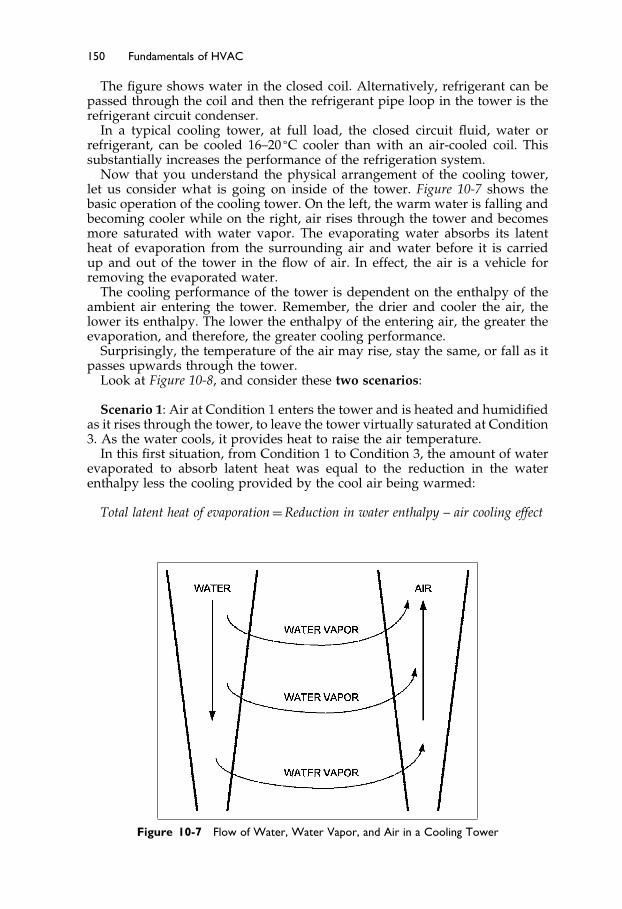
Elsevier UK Ch10-P373998 3-11-2006 7:38a.m. Page:150 Trimsize:6.5×9.5inches
Basal Font:Palatino Margins:Top:40pt Gutter:55pt Font Size:10/11 Text Width:29pc Depth:51 Lines
150 Fundamentals of HVAC
The figure shows water in the closed coil. Alternatively, refrigerant can bepassed through the coil and then the refrigerant pipe loop in the tower is therefrigerant circuit condenser.
In a typical cooling tower, at full load, the closed circuit fluid, water orrefrigerant, can be cooled 16–20 �C cooler than with an air-cooled coil. Thissubstantially increases the performance of the refrigeration system.
Now that you understand the physical arrangement of the cooling tower,let us consider what is going on inside of the tower. Figure 10-7 shows thebasic operation of the cooling tower. On the left, the warm water is falling andbecoming cooler while on the right, air rises through the tower and becomesmore saturated with water vapor. The evaporating water absorbs its latentheat of evaporation from the surrounding air and water before it is carriedup and out of the tower in the flow of air. In effect, the air is a vehicle forremoving the evaporated water.
The cooling performance of the tower is dependent on the enthalpy of theambient air entering the tower. Remember, the drier and cooler the air, thelower its enthalpy. The lower the enthalpy of the entering air, the greater theevaporation, and therefore, the greater cooling performance.
Surprisingly, the temperature of the air may rise, stay the same, or fall as itpasses upwards through the tower.
Look at Figure 10-8, and consider these two scenarios:
Scenario 1: Air at Condition 1 enters the tower and is heated and humidifiedas it rises through the tower, to leave the tower virtually saturated at Condition3. As the water cools, it provides heat to raise the air temperature.
In this first situation, from Condition 1 to Condition 3, the amount of waterevaporated to absorb latent heat was equal to the reduction in the waterenthalpy less the cooling provided by the cool air being warmed:
Total latent heat of evaporation = Reduction in water enthalpy – air cooling effect
Figure 10-7 Flow of Water, Water Vapor, and Air in a Cooling Tower

Elsevier UK Ch10-P373998 3-11-2006 7:38a.m. Page:151 Trimsize:6.5×9.5inches
Basal Font:Palatino Margins:Top:40pt Gutter:55pt Font Size:10/11 Text Width:29pc Depth:51 Lines
Central Plants 151
Figure 10-8 Cooling Tower Psychrometric Chart For Air
Scenario 2: In contrast, when warmer air, at roughly the same enthalpy,enters the tower at Condition 2, it will be cooled and humidified as it passesthrough the tower to leave at Condition 3. The reduction in air temperature isachieved through additional evaporation.
In this situation, from Condition 2 to Condition 3, the amount of waterevaporated to absorb latent heat was equal to the reduction in enthalpy of thewater plus the heat required to lower the air temperature:
Total latent heat of evaporation = Reduction in water enthalpy + air heating effect
Overall, the tower has approximately the same cooling effect on the waterfor entering air with the same enthalpy whatever the entering air temperature.However, with the same enthalpy, as the air becomes hotter and dryer moreevaporation will take place.
The tower capacity can be reduced in several ways. The fan can be cycledon-and-off, but the frequent starts are very hard on the motor. Better, for bothenergy conservation and motor life, is to use a two-speed motor and cyclebetween high, low, and off. For slightly better control and energy savings, avariable speed fan can be used.
The water that is evaporated leaves behind any dissolved chemicals. At fullload this can be as much as 1% of flow. In addition, the water cleans the air,removing dust and debris. Since the water is warm and full of nutrients, it isan ideal site for bacterial growth, legionella in particular. It is thus critical thatthe tower be regularly cleaned and treated to prevent biological growth.
The Next Step
We have considered components, systems, and, in this chapter, central plant.Along the way, equipment has been “controlled” and energy saving has beenmentioned. In the next chapter, we will focus on controls and how they work.We will revisit several of the systems you have already studied, and consider
Elsevier UK Ch10-P373998 3-11-2006 7:38a.m. Page:152 Trimsize:6.5×9.5inches
Basal Font:Palatino Margins:Top:40pt Gutter:55pt Font Size:10/11 Text Width:29pc Depth:51 Lines
152 Fundamentals of HVAC
their particular control features. Then after controls, we will consider energyconservation in Chapter 12.
Summary
This chapter has been concerned with central plant, specifically with boilers,producing steam or hot water, chillers producing chilled water, and coolingtowers that cool the chillers.
10.2 Introduction
Central plants generally require less maintenance than numerous smaller pack-age systems and the equipment usually has a longer life. Other advantagesinclude ease of operation and maintenance in a central location; efficiency;heat recovery options; less maintenance and a longer life. Cons include: costof installation, space requirements for the equipment and for the distributionpipes. Issues of seasonal efficiency were also raised.
10.3 Central Plant versus Local Plant in a Building
Issues that can influence the choice include installation costs vs. operating costs.For minimum installation cost, the package approach usually wins. However,the central plant has several operational benefits.
10.4 Boilers
Boilers are pressure vessels used to produce steam or hot water. The criticaldesign factor for boilers is pressure. A low-pressure steam boiler operates at apressure of no more than 100 kPa. Low-pressure hot water boilers are allowedup to 1100 kPa.
Boilers and system components are covered by local code requirements. Thesafety equipment and staff monitoring requirements are far less stringent forlow-pressure boilers so there is a significant incentive to use low-pressure.
Boilers have two sections: The combustion section is the space where thefuel-air mixture burns; the second section of the boiler is the heat transfersection. In all boilers there is a need to modulate the heat input. On smallerunits, the efficiency improves and cycling effect is reduced by having a “high-low-off” burner. On larger units, a modulating burner can adjust the outputfrom 100% down to some minimum output. The burner modulation range iscalled the “turn-down ratio.” With a modulating burner, efficiency increases asthe output drops and efficiency drops as the mean temperature of the heatedfluid rises.
Boilers can run in parallel: With two water boilers, about half the water willflow through each boiler; with steam boilers, if one is running both will fillwith steam to the same pressure.
In steam systems, there is a constant loss of water in the condensate returnsystem. To prevent problems with solids build-up in the boiler and distributionpipe corrosion, continuous high quality water treatment is required.
Elsevier UK Ch10-P373998 3-11-2006 7:38a.m. Page:153 Trimsize:6.5×9.5inches
Basal Font:Palatino Margins:Top:40pt Gutter:55pt Font Size:10/11 Text Width:29pc Depth:51 Lines
Central Plants 153
10.5 Chillers
Chillers are refrigeration machines with water, or brine, heating the evapora-tor. The standard measure of chiller capacity is the kilowatt, a heat absorptioncapacity of 100 watts. The main difference between chillers is the type of com-pressor. Smaller compressors are often reciprocating units, larger units mayhave screw or scroll positive-displacement compressors, and for 250 kilowattsup to the largest machines, there is the centrifugal compressor.
Chillers should be sized to match the estimated load without a ‘safety’ factor.An oversized chiller will have a lower operating efficiency, so it will have ahigher operating and maintenance cost, as well as more difficulty dealing withlow loads. When designing a central plant, it is often worth having two 50%capacity chillers instead of a single chiller. If failure to meet the load is missioncritical, use two units sized to 50% of the load each, with a third 50% unit asstandby.
10.6 Cooling Towers
Cooling towers are a particular type of big evaporative cooler. In the coolingtower, warm water is exposed to a flow of air, causing evaporation, and,therefore, cooling of the water.
The psychrometric chart can be used to illustrate the workings of the cool-ing tower.
It is often considered worthwhile to over-size the tower to ensure that fullchiller capacity will always be available. The tower capacity can be reducedby using a fan that can be cycled on and off; with a two-speed motor that cancycle between high, low, and off; or a variable speed fan can be used.
A danger of cooling towers arises from the warm, nutrient-rich environmentthat can propagate bacteria growth; therefore, the tower should be regularlycleaned and treated to prevent biological growth. In addition, some water mustbe bled off to prevent the build-up of dissolved solids.
Bibliography
ASHRAE. 2004. 2004 ASHRAE Handbook—HVAC Systems and Equipment. Atlanta: Amer-ican Society of Heating, Refrigerating and Air-Conditioning Engineers, Inc.
ASHRAE. 2003. 2003 ASHRAE Handbook—HVAC Applications. Atlanta: American Soci-ety of Heating, Refrigerating and Air-Conditioning Engineers, Inc.
ASME. 2004. 2004 ASME Boiler and Pressure Vessel Code. New York: American Societyof Mechanical Engineers.

Elsevier UK Ch11-P373998 3-11-2006 7:40a.m. Page:154 Trimsize:6.5×9.5inches
Basal Font:Palatino Margins:Top:40pt Gutter:55pt Font Size:10/11 Text Width:29pc Depth:51 Lines
Chapter 11
Controls
Contents of Chapter 11
InstructionsObjectives of Chapter 1111.1 Introduction11.2 Controls Basics11.3 Typical Control Loops11.4 Introduction to Direct Digital Control (DDC)11.5 Direct Digital Control of an Air-Handler11.6 Architecture and Advantages of Direct Digital ControlsThe Next StepSummaryBibliography
Instructions
Read the material of Chapter 11. Re-read the parts of the chapter that areemphasized in the summary and memorize important definitions.
Objectives of Chapter 11
Chapter 11 starts off by describing the basics of control and introducing youto some of the terminology of HVAC controls. After this introduction, weconsider the physical structure and software of Direct Digital Control (DDC)systems. In this section, we demonstrate some of the control possibilities thatare available with DDC by revisiting some of the references to controls inearlier chapters. Finally, there is a brief introduction to the architecture ofDDC systems and their advantages. After studying the chapter, you should beable to:
Explain the following terms: normally open valve, modulating, proportionalcontrol, controlled variable, setpoint, sensor, controller, and controlleddevice.
Describe an open control loop and a closed control loop and explain thedifference between them.

Elsevier UK Ch11-P373998 3-11-2006 7:40a.m. Page:155 Trimsize:6.5×9.5inches
Basal Font:Palatino Margins:Top:40pt Gutter:55pt Font Size:10/11 Text Width:29pc Depth:51 Lines
Controls 155
Explain how the DDC system replaces conventional controllers.List the four main DDC point types and give an example of each one.Explain how the knowledge in a DDC system can be put to good use.
11.1 Introduction
Every piece of equipment that we have introduced in this course requires con-trols for operation. Some equipment, such as a rooftop package unit, will likelycome with factory-installed controls, except for the thermostat. The thermo-stat has to be mounted in the space and wired to the packaged unit. In otherbuilt-up systems, every control component may be specified by the designerand purchased and installed under a separate contract from the rest of theequipment.
Whether the controls are a factory package or built-up on site, well-designedcontrols are a critical part of any HVAC system. The controls for a system maydiffer from project to project for a number of reasons. Design considerations forcontrols choices include availability of expertise in maintenance and operationsof the controls, repair and maintenance expense budgets, and capital costs ofcontrol equipment.
To elaborate, one should always choose controls that are suited to the avail-able maintenance and repair expertise and availability. Find out how the clientwill be arranging maintenance of the system. As an example, it is generallyunwise to choose the latest and greatest high-tech controls for a remote school,unless the school has a maintenance system in place to support the controls. Itis generally better to aim for simplicity and reliability in this type of situation.
On the other hand, if the client has experienced, well-trained, controls staffavailable, on site or by contract, there is an opportunity to specify somethingquite sophisticated. As always, economics plays a controlling role and thechallenge is to demonstrate how the sophisticated computerized system willperform better and save energy compared to a simple off-the-shelf option.
There are several types of controls and each has specific features that make itthe best choice in particular circumstances. The following is a brief introductionto the main types.
Control Types
Controls fall into broad categories based on a particular feature.Self-powered Controls require no external power. Various radiator valves
and ceiling VAV diffusers have self-powered temperature controls. These unitsare operated by the expansion and contraction of a bellows that is filled with awax that has a high coefficient of expansion. As the temperature rises, the waxexpands, lengthening the bellows. This closes the radiator valve (cuts back onheating) or opens the VAV diffuser (increases the cooling). The advantage ofthese units is that they require no wiring or other connection so installationcost is minimal.
Electric Controls are powered by electricity. We will introduce two types ofelectric controls in this course:
On/off Electric Controls are used in almost every system to turn electricalequipment on and off. The electric thermostat is the most commonexample.
Elsevier UK Ch11-P373998 3-11-2006 7:40a.m. Page:156 Trimsize:6.5×9.5inches
Basal Font:Palatino Margins:Top:40pt Gutter:55pt Font Size:10/11 Text Width:29pc Depth:51 Lines
156 Fundamentals of HVAC
Modulating Electric Controls are based on small electric motors and resistorsthat provide variable control.
Pneumatic Controls are controls that use air pressure. The signal transmissionis by air pressure variation and control effort is through air pressure on adiaphragm or piston. For example, a temperature sensor may vary the pres-sure to the controller in the range of 20 kPa to 100 kPa. The controller willcompare the thermostat line pressure with the setpoint pressure and, based onthe difference, adjust the pressure to the heating valve to open, or to close, thevalve. The heating valve will typically have a spring to drive it fully open andthe increasing air pressure will close the valve against the spring. The valveis called a “normally open” valve, since failure of the air system would haveair pressure fall to zero and the spring would open the valve. A “normallyclosed” valve is the opposite, with the spring holding it closed until the airpressure opens the valve.
Pneumatic controls require a continuous source of compressed air at 100 kPafor sensing and controlling. When considering the total cost of the pneumaticsystem, the provision of the compressor(s), the operation and maintenance cost,and the energy lost with leaks have to be factored into the total cost. However,the pneumatic system does have the advantage of relatively inexpensive andpowerful actuators (a device that moves a valve or damper) and it is relativelyeasy to learn to maintain and service.
Electronic Controls, or more correctly Analog Electronic Controls, use vary-ing voltages and currents in semiconductors to provide modulating controls.They have never found great acceptance in the HVAC industry, since DirectDigital Controls offered much more usability at a much lower price.
Direct Digital Controls (DDC) are controls operated by one or more smallcomputer processors (microprocessors). The computer processor uses a soft-ware program of instructions to make decisions based on the available inputinformation. The processor operates only with digital signals and has a varietyof built-in interface components so that it can receive information and outputcontrol signals.
There are many instances where the types of controls are mixed. For exam-ple a DDC system could have all electric “sensors,” the units that measuretemperature, humidity, pressure, or other variable properties. This same sys-tem may also have pneumatic actuators on all the valves, since pneumaticsprovide considerable power and control at low cost. A “transducer” createsthe interface between the electrical output of the DDC system and the valve.The transducer takes in the DDC signal, say a voltage between zero and tenvolts, and converts it to an output of 20 kPa to 100 kPa. Thus, at zero volts theoutput will be 20 kPa, rising to 100 kPa at ten volts.
We will spend considerable time on DDC controls later in the chapter. Fornow, let us consider the basics of controls—what makes them work.
11.2 Controls Basics
You instinctively know about control. You control all sorts of actions in yourdaily life. In this section we are going to introduce the basic ideas of controls.Your understanding of the rest of the chapter depends on your being reallycomfortable with the ideas in this section. Take the time to think about theideas presented and how controls operate.
Elsevier UK Ch11-P373998 3-11-2006 7:40a.m. Page:157 Trimsize:6.5×9.5inches
Basal Font:Palatino Margins:Top:40pt Gutter:55pt Font Size:10/11 Text Width:29pc Depth:51 Lines
Controls 157
We are going to start with the simplest of controls, “on-off.” As the nameimplies, the element being controlled is either “on,” or “off.”
Consider a domestic hot water tank with a thermostatically con-trolled electric heating element near the bottom. Water becomes lessdense as it is heated above 4�1 �C, so as the element heats the water,hot water will rise to the top. When the water at the thermostati-cally controlled element is hot, all the water above it is hot and thethermostat will turn off the heating element.
Now, let us assume someone runs a little hot water. Cold waterenters the bottom of the tank and cools the thermostat. The thermo-stat switches the element “on” and soon the tank is filled with allhot water once more. Suppose that later, one person runs a showeras someone else is running hot water for washing clothes. Althoughthe element will come on, it can’t keep up with this large load. Verysoon all the hot water is gone and the tank is full of cold water. Bothusers turn off the taps. The element at the bottom of the tank willslowly heat the whole tank back up to the required temperature.
In order to achieve a quick recovery of hot water, we need a second elementnear the top of the tank. An element near the top of the tank only has to heat thewater above it, so it will get a small amount of water up to temperature muchmore quickly. Now we have two elements. Do we need them on at the sametime? No. If the top element is needed, the bottom element is not needed. So,when the top element turns on, for quick recovery, it also breaks the circuit tothe bottom element. Once the water above the top element is hot, that elementswitches “off” and the bottom element switches “on” to heat the rest of thewater in the tank. This gives us an “either/or” control decision—either the topor the bottom element can be “on.”
The result is a tank that heats a little water quickly, and, in a much longertime, heats the full tank, with the electrical load of one heating element.
This is a simple example of how “on-off” controls can be cascaded to producesimple, but very effective, control. With some ingenuity, quite complex andextremely reliable electric controls can be developed.
Now let us move from “on-off” to “modulating” controls. Modulating means“variable.” One type of modulating control is proportional control. This isbest explained with a demonstration.
Take a jug and fill it with water.Take a tumbler, and place it in a spot that won’t be damaged if water
overflows (like in a sink).Next, see how quickly you can use the jug to fill the glass so that the water
level is right up at the rim of the glass – so full you’d need a very steadyhand to drink it!
If you didn’t actually do the task, take a few moments to relax, and visualizethe empty glass with the full jug on the table beside it. The jug is heavy asyou pick it up and start to pour. You hear the water flowing in, feel yourselftipping the jug, see the level rising and feel that tension as you slow the flowto drips, to make it just reach the top, and then you stop pouring.
What happens? When you see the glass empty or just starting to fill, thewater level is a long way from the rim. Naturally, you start pouring quite

Elsevier UK Ch11-P373998 3-11-2006 7:40a.m. Page:158 Trimsize:6.5×9.5inches
Basal Font:Palatino Margins:Top:40pt Gutter:55pt Font Size:10/11 Text Width:29pc Depth:51 Lines
158 Fundamentals of HVAC
quickly. As the glass fills, you slow the flow until you’re just dripping the waterin, to get the glass quite full, to the rim, without going over. The change in rateat which you pour is roughly proportional to the distance of the water from therim. This change in rate is called the gain. You are acting as a “proportionalcontroller.”
Proportional control is the basis of the majority of control loops—the rate isproportional to the distance from the target—the setpoint.
Now imagine a more complicated scenario of proportional control. In thisscenario, we will be demonstrating offset and overshoot.
Someone has attached a hose to the bottom of your glass and runsit to a tap downstairs, out of your sight. Your job, now, is to keepthe glass full. You fill the glass, and then you notice the level isdropping slowly. In response, you start to pour slowly, just keepingthe glass near full. Then, you realize the level is dropping faster, soyou tip the jug. Suddenly the glass is full–it is overflowing!
What happened?
Initially, the hose tap was opened just a little, and it was easy foryou to pour slowly to keep the level near the rim. When the tapwas opened wide, though, the jug had to be tipped a lot to keep up,so when the tap was suddenly closed, it took a moment for you torealize that the water level in the glass was rising rapidly. It tookanother moment—too long—to straighten the jug and stop the flow,and the water overflowed over the top of the glass.
Just like you, a control system has an easy time with slow steady changes.But you had to notice that the water level had dropped before you started topour. This created a time delay. Note also that you attempted to keep the glassalmost full rather than totally full. This represented an “offset” from target,the setpoint. Then, when the glass started to drain rapidly you poured faster,to keep it from being empty, rather than trying to maintain the level just atthe rim—even more offset.
Finally, the drain on your glass stopped, and you were too slow to straightenthe jug and stop the flow. The water overflowed—serious “overshoot”! Thisovershoot could have been reduced if you had been restricted on how fast youcould pour. If you had less gain you would have had less ability to keep upwith sudden changes and the overshoot would have been much less.
You now have some feel for controls and what they do. There are manyadded refinements to controller action that are explained in the ASHRAELearning Institute course, Fundamentals of HVAC Control Systems.1
Now consider some real HVAC examples.There are two types of controls: “closed loop” and “open loop.” Let us start
by considering the main components of a closed loop control as shown inFigure 11-1.
Closed Loop
The top half of Figure 11-1 illustrates a simple air heating control loop. Atemperature sensor measures the temperature of the heated air and sendsthat information to the controller. The controller is also provided with the
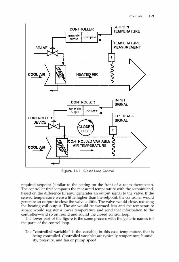
Elsevier UK Ch11-P373998 3-11-2006 7:40a.m. Page:159 Trimsize:6.5×9.5inches
Basal Font:Palatino Margins:Top:40pt Gutter:55pt Font Size:10/11 Text Width:29pc Depth:51 Lines
Controls 159
Figure 11-1 Closed Loop Control
required setpoint (similar to the setting on the front of a room thermostat).The controller first compares the measured temperature with the setpoint and,based on the difference (if any), generates an output signal to the valve. If thesensed temperature were a little higher than the setpoint, the controller wouldgenerate an output to close the valve a little. The valve would close, reducingthe heating coil output. The air would be warmed less and the temperaturesensor would register a lower temperature and send that information to thecontroller—and so on round and round the closed control loop.
The lower part of the figure is the same process with the generic names forthe parts of the control loop.
The “controlled variable” is the variable, in this case temperature, that isbeing controlled. Controlled variables are typically temperature, humid-ity, pressure, and fan or pump speed.
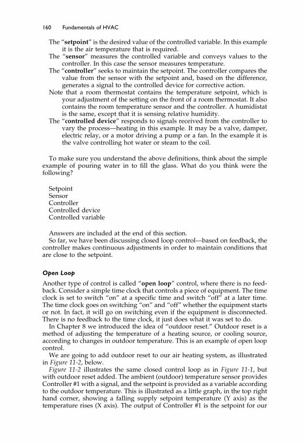
Elsevier UK Ch11-P373998 3-11-2006 7:40a.m. Page:160 Trimsize:6.5×9.5inches
Basal Font:Palatino Margins:Top:40pt Gutter:55pt Font Size:10/11 Text Width:29pc Depth:51 Lines
160 Fundamentals of HVAC
The “setpoint” is the desired value of the controlled variable. In this exampleit is the air temperature that is required.
The “sensor” measures the controlled variable and conveys values to thecontroller. In this case the sensor measures temperature.
The “controller” seeks to maintain the setpoint. The controller compares thevalue from the sensor with the setpoint and, based on the difference,generates a signal to the controlled device for corrective action.
Note that a room thermostat contains the temperature setpoint, which isyour adjustment of the setting on the front of a room thermostat. It alsocontains the room temperature sensor and the controller. A humidistatis the same, except that it is sensing relative humidity.
The “controlled device” responds to signals received from the controller tovary the process—heating in this example. It may be a valve, damper,electric relay, or a motor driving a pump or a fan. In the example it isthe valve controlling hot water or steam to the coil.
To make sure you understand the above definitions, think about the simpleexample of pouring water in to fill the glass. What do you think were thefollowing?
SetpointSensorControllerControlled deviceControlled variable
Answers are included at the end of this section.So far, we have been discussing closed loop control—based on feedback, the
controller makes continuous adjustments in order to maintain conditions thatare close to the setpoint.
Open Loop
Another type of control is called “open loop” control, where there is no feed-back. Consider a simple time clock that controls a piece of equipment. The timeclock is set to switch “on” at a specific time and switch “off” at a later time.The time clock goes on switching “on” and “off” whether the equipment startsor not. In fact, it will go on switching even if the equipment is disconnected.There is no feedback to the time clock, it just does what it was set to do.
In Chapter 8 we introduced the idea of “outdoor reset.” Outdoor reset is amethod of adjusting the temperature of a heating source, or cooling source,according to changes in outdoor temperature. This is an example of open loopcontrol.
We are going to add outdoor reset to our air heating system, as illustratedin Figure 11-2, below.
Figure 11-2 illustrates the same closed control loop as in Figure 11-1, butwith outdoor reset added. The ambient (outdoor) temperature sensor providesController #1 with a signal, and the setpoint is provided as a variable accordingto the outdoor temperature. This is illustrated as a little graph, in the top righthand corner, showing a falling supply setpoint temperature (Y axis) as thetemperature rises (X axis). The output of Controller #1 is the setpoint for our

Elsevier UK Ch11-P373998 3-11-2006 7:40a.m. Page:161 Trimsize:6.5×9.5inches
Basal Font:Palatino Margins:Top:40pt Gutter:55pt Font Size:10/11 Text Width:29pc Depth:51 Lines
Controls 161
Figure 11-2 Open and Closed Control Loops
closed loop controller. The open loop measures temperature and provides anoutput. It has no involvement with the result; it just does its routine—openloop control—no feedback.
Alternatively, we could have chosen to use a chilled water system and to useoutdoor reset to raise the chilled water temperature as the outside temperaturedropped.
Outdoor reset is a common requirement, so manufacturers frequently pack-age the two controllers into one housing and call it a “reset controller.” Thispackaging of several components of the control loop is similar to the thermo-stat package where the setpoint, the temperature sensor, and the controller arepackaged in one little box.
11.3 Typical Control Loops
Having considered the basics of control loops in the previous section, nowlook at some real, more complete, control loops. We will start by adding timecontrol, another open loop, to our previous example, as Figure 11-3.
A time clock now provides power to the controllers according to a schedule.Typical commercial thermostats include the 5-1-1 time clock function. 5-1-1means that they have independent time schedules for the 5 weekdays, 1 forSaturday, and 1 for Sunday.
The system shown also has a manual-override switch that allows theoccupant to switch the system ’on’ when the time clock has it “off.” There is an
Answer to previous page’s example:Setpoint – top edge of the glass, Sensor – Your eye, Controller – your brain, Controlleddevice – the jug of water, Controlled variable – depth of water in the glass
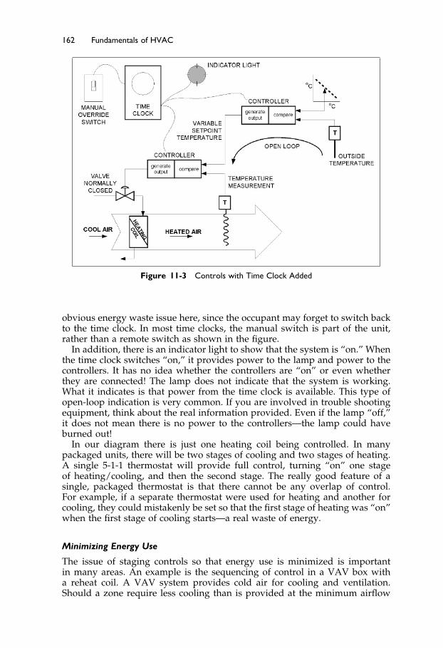
Elsevier UK Ch11-P373998 3-11-2006 7:40a.m. Page:162 Trimsize:6.5×9.5inches
Basal Font:Palatino Margins:Top:40pt Gutter:55pt Font Size:10/11 Text Width:29pc Depth:51 Lines
162 Fundamentals of HVAC
Figure 11-3 Controls with Time Clock Added
obvious energy waste issue here, since the occupant may forget to switch backto the time clock. In most time clocks, the manual switch is part of the unit,rather than a remote switch as shown in the figure.
In addition, there is an indicator light to show that the system is “on.” Whenthe time clock switches “on,” it provides power to the lamp and power to thecontrollers. It has no idea whether the controllers are “on” or even whetherthey are connected! The lamp does not indicate that the system is working.What it indicates is that power from the time clock is available. This type ofopen-loop indication is very common. If you are involved in trouble shootingequipment, think about the real information provided. Even if the lamp “off,”it does not mean there is no power to the controllers—the lamp could haveburned out!
In our diagram there is just one heating coil being controlled. In manypackaged units, there will be two stages of cooling and two stages of heating.A single 5-1-1 thermostat will provide full control, turning “on” one stageof heating/cooling, and then the second stage. The really good feature of asingle, packaged thermostat is that there cannot be any overlap of control.For example, if a separate thermostat were used for heating and another forcooling, they could mistakenly be set so that the first stage of heating was “on”when the first stage of cooling starts—a real waste of energy.
Minimizing Energy Use
The issue of staging controls so that energy use is minimized is importantin many areas. An example is the sequencing of control in a VAV box witha reheat coil. A VAV system provides cold air for cooling and ventilation.Should a zone require less cooling than is provided at the minimum airflow

Elsevier UK Ch11-P373998 3-11-2006 7:40a.m. Page:163 Trimsize:6.5×9.5inches
Basal Font:Palatino Margins:Top:40pt Gutter:55pt Font Size:10/11 Text Width:29pc Depth:51 Lines
Controls 163
Figure 11-4 VAV Box with Reheat
for ventilation, then the reheat coil is turned on. In the control system for thebox, there are two important requirements:
1. The heating coil must only be activated at minimum airflow.2. There must be minimal cycling between “coil on” and “coil off.”
To achieve this, a single controller is used to control both the airflow and thecoil, in sequence. The heating valve and volume damper are normally closed.The volume damper has a minimum setting for minimum ventilation.
As an example, the box and controller actions are shown in Figure 11-4.Starting on the left, when the space is cold, the controller opens the heatingvalve fully. As the zone warms up, the controller closes the heating valve. Oncethe heating valve is closed, there is a dead band of temperature change (noheating, no additional cooling) before the controller starts to open the volumedamper to increase the cooling up to maximum.
In addition to the simple control loops we have discussed, there are morecomplex loops that have many inputs. Staying with VAV for a moment, thereare many systems where the fan speed is controlled by the requirements ofthe VAV boxes. A system, for example, might have 50 or more boxes. Wewant each to have enough air but we don’t want to run the fan any more thanneeded. To manage this, we need to know when each box has adequate airflowing through it.
A VAV box has enough air if its damper is not fully open. Thus, we wouldbe very confident that if every box has its damper at less that 95% open, thereis enough air pressure in the system. However, determining if every box meetsthis condition is only practical in a DDC system. We will begin to examinethese DDC systems in the next section.
11.4 Introduction to Direct Digital Control (DDC)
As briefly mentioned earlier, small computer processors (microprocessors)operate Direct Digital Controls. “Digital” means that they operate on a seriesof pulses. In the DDC system, all the inputs and outputs remain, however,they are not processed in the controllers, but are carried out in a computer,based on instructions called the “control logic.”

Elsevier UK Ch11-P373998 3-11-2006 7:40a.m. Page:164 Trimsize:6.5×9.5inches
Basal Font:Palatino Margins:Top:40pt Gutter:55pt Font Size:10/11 Text Width:29pc Depth:51 Lines
164 Fundamentals of HVAC
Figure 11-5 Control Scheme (from Figure 11-3) without Controlling Components
Figure 11-5 shows the same control diagram that we saw in Figure 11-3, butwith the controlling components, (the time clock, and the two controllers),blanked out. All the system that has been blanked out is now replaced bysoftware activity in the computer.
In Figure 11-5, each input to or output from the DDC computer has beenidentified as one of the following
On/off input – manual switchOn/off output – power to lightVariable input – temperature from sensorVariable output – power to the valve
These are the four main types of input and output in a control system. Let’sconsider each one briefly in terms of a DDC system.
On/off input. A switch, a relay, or another device closes, making a cir-cuit complete. This on/off behavior has traditionally been called “dig-ital.” Therefore in DDC terms it is generally called a “Digital Input,”or DI.
The term “digital” is not considered technically correct, since there is noseries of pulses, just one “on” or “off.” Thus, for on/off points the term“binary” is considered more correct, and the term is being encouragedin place of “digital.” So, “binary input,” BI, is the officially approveddesignation of an “on/off” input.
On/off output. The on/off output either provides power or it does not.The lamp is either powered, “on,” or not powered, “off.” In a similarway, this is called a “Digital Output,” DO, or more correctly, binaryoutput, BO.

Elsevier UK Ch11-P373998 3-11-2006 7:40a.m. Page:165 Trimsize:6.5×9.5inches
Basal Font:Palatino Margins:Top:40pt Gutter:55pt Font Size:10/11 Text Width:29pc Depth:51 Lines
Controls 165
Variable input. A varying signal, such as temperature, humidity, or pres-sure, is called an “analog” signal. In DDC terms, the input signal froman analog, or varying, signal is called an “Analog Input,” or AI.
Variable output. In the same way, the variable output to open or closea valve, to adjust a damper, or to change fan speeds, is an “AnalogOutput,” AO.
You might think the next step is to connect these DI, DO, AI, AO pointsto the computer. Things are not quite that simple. A sensor that measurestemperature produces an analog, varying signal and our computer needs adigital signal. So between each AI device and the processor there is an “A/D,”“analog to digital,” device. These A/D devices, for AIs, are usually embeddedwith the computer.
Similarly, for AO points there is a “D/A,” or “digital to analog,” devicethat converts the digital signal to a 0–10 volts or 4–20 milliamp electricalsignal. This signal has too little power to operate a valve or damper. If, forexample, the controlled device is a valve that is powered by compressed air,the analog electrical signal will go to a “transducer” in which the electricalsignal will be converted to an air pressure that drives the valve. If the valve iselectrically powered, the transducer will convert the low power, analog signalto a powerful electric current.
Only standard telephone cable is required to carry the analog electricalsignal, hence the transducer is often separate from the processor and closeto the controlled device. This is because it is far less effort, and cost, to runstandard telephone cabling to the transducer rather than to run the air line (orelectric power cable) to the processor location and back to the valve.
Naming Conventions
In a DDC system every input and every output must have a unique name.There are a variety of naming conventions depending on personal preferenceand the size and complexity of the system. Many are based on a hierarchy ofelements such as
Type – Building – System – Point – Detail
“Detail” allows for a number of identical points, VAV boxes for example. Ifwe assume our build is called “NEW,” our points list might be:
AI NEW AH1 OAT AI, in NEW, on air-handler1, outside air temperatureAI NEW AH1 DT AI, in NEW, on air-handler 1, duct temperatureAO NEW AH1 DT AO, in NEW, on air-handler1, duct temperature
controlDI NEW AH1 MAN DI, in NEW, on air-handler1, manual controlDO NEW AH1 IND DO, in NEW, on air-handler1, indicator light
Sequence of Operations
Now look back at Figure 11-5. As we noticed earlier, the controllers and timeclock are all blanked out. In a DDC system, all the actions of the controllers andtime clock are carried out through software in the small computer processor.The software is a set of ordered operations, which is often called the “sequence

Elsevier UK Ch11-P373998 3-11-2006 7:40a.m. Page:166 Trimsize:6.5×9.5inches
Basal Font:Palatino Margins:Top:40pt Gutter:55pt Font Size:10/11 Text Width:29pc Depth:51 Lines
166 Fundamentals of HVAC
of operation.” What do we require our software to do? The following is a verysimple “English Language” sequence of operations.
Do the following things:
If the time is between xx:xx a.m. and yy:yy p.m. run mode is ‘ON’, otherwise runmode is ‘OFF’
If the manual switch is closed, DI, run mode is ‘ON’If run mode is ‘OFF’ close heating valveIf the system is in run mode ‘ON’, do the following commands
Check ambient temperature, AI, and remember the value as ‘ambient’Using ‘ambient’, lookup required setpoint from (graphic) schedule to find
required air setpoint temperature. Remember this value as ‘setpoint’Check air temperature in the duct, AI, and remember it as ‘temperature’If ‘temperature’ is less than ‘setpoint’ increase output to valve, AOIf ‘temperature’ is greater than ‘setpoint’ decrease output to valve, AO
Go back to the beginning
These instructions are typically written into the DDC processor using astandard personal computer, PC. The programming may be a more formalversion of our little example, or may use graphic symbols instead. The DDCprocessor can also be programmed to sound alarms, issue warnings, writemessages, plot graphs, and draw graphics through the PC.
So now we can redraw Figure 11-5, to show the DDC system, Figure 11-6.As it is shown, there is no way of accessing the processor. In a real system,
there is a communication connection providing access from a computer, typi-cally a desktop PC or a laptop computer. The PC has many names including“the operator interface,” “front end,” or “operator machine interface” (OMI).Assuming that this panel has everything it needs to run the system, it is calleda “standalone panel.” Standalone means it has everything to keep running onits own.
Figure 11-6 DDC Control Schematic
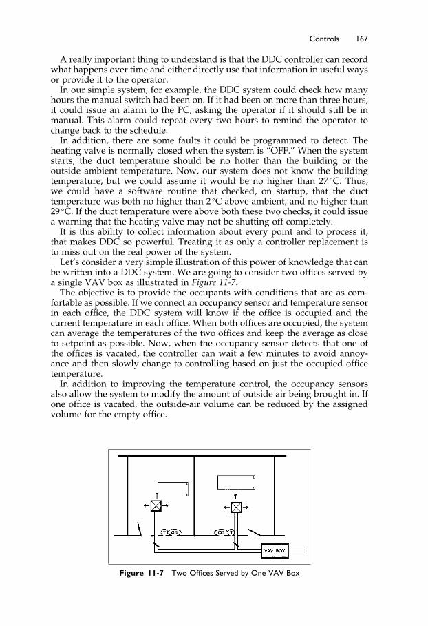
Elsevier UK Ch11-P373998 3-11-2006 7:40a.m. Page:167 Trimsize:6.5×9.5inches
Basal Font:Palatino Margins:Top:40pt Gutter:55pt Font Size:10/11 Text Width:29pc Depth:51 Lines
Controls 167
A really important thing to understand is that the DDC controller can recordwhat happens over time and either directly use that information in useful waysor provide it to the operator.
In our simple system, for example, the DDC system could check how manyhours the manual switch had been on. If it had been on more than three hours,it could issue an alarm to the PC, asking the operator if it should still be inmanual. This alarm could repeat every two hours to remind the operator tochange back to the schedule.
In addition, there are some faults it could be programmed to detect. Theheating valve is normally closed when the system is “OFF.” When the systemstarts, the duct temperature should be no hotter than the building or theoutside ambient temperature. Now, our system does not know the buildingtemperature, but we could assume it would be no higher than 27 �C. Thus,we could have a software routine that checked, on startup, that the ducttemperature was both no higher than 2 �C above ambient, and no higher than29 �C. If the duct temperature were above both these two checks, it could issuea warning that the heating valve may not be shutting off completely.
It is this ability to collect information about every point and to process it,that makes DDC so powerful. Treating it as only a controller replacement isto miss out on the real power of the system.
Let’s consider a very simple illustration of this power of knowledge that canbe written into a DDC system. We are going to consider two offices served bya single VAV box as illustrated in Figure 11-7.
The objective is to provide the occupants with conditions that are as com-fortable as possible. If we connect an occupancy sensor and temperature sensorin each office, the DDC system will know if the office is occupied and thecurrent temperature in each office. When both offices are occupied, the systemcan average the temperatures of the two offices and keep the average as closeto setpoint as possible. Now, when the occupancy sensor detects that one ofthe offices is vacated, the controller can wait a few minutes to avoid annoy-ance and then slowly change to controlling based on just the occupied officetemperature.
In addition to improving the temperature control, the occupancy sensorsalso allow the system to modify the amount of outside air being brought in. Ifone office is vacated, the outside-air volume can be reduced by the assignedvolume for the empty office.
Figure 11-7 Two Offices Served by One VAV Box

Elsevier UK Ch11-P373998 3-11-2006 7:40a.m. Page:168 Trimsize:6.5×9.5inches
Basal Font:Palatino Margins:Top:40pt Gutter:55pt Font Size:10/11 Text Width:29pc Depth:51 Lines
168 Fundamentals of HVAC
Finally, when both offices are empty, the system does not need to maintainthe temperature to the same tight limits, and there is no requirement forventilation air, so, if there is no thermal load, the VAV box can be completelyclosed. Similar to the example of CO2 control in Chapter 4, Section 4.5, thesystem only provides service to occupants who are present.
There is one more advantage. The system can be designed to prevent thelights being left on for long periods when the office is unoccupied. One methodis to provide power to the lighting circuits (not switch them on, just providepower) when the room is sensed as being occupied. The occupant can switchthe light on and off when they like, but when they leave, it will soon go out.The system delays turning the light off for several minutes, to avoid annoyancewhen the occupant is only away for a few minutes.
This section has introduced you to basic ideas of DDC.
• The sensors and actuators stay, but all the control logic is in the software.• There are four types of input and output, DO (BO), DI (BI), AO, and AI.• The software is a set of instructions that the DDC system can interpret and
act upon.
In the next section, we are going to consider the points and sequence ofoperation of an air-handler. Then in Section 11.6 we will consider how DDCunits can be interconnected, and can share information with each other andthe operators to make a full-scale control system, rather than a collection ofcontrol loops.
11.5 Direct Digital Control of an Air-Handler
In this section we are going to consider a constant-volume air handler servinga single zone, designated “001.” The air handler uses space temperature forcontrol, with no mixed air control, unlike air handlers that we have discussedbefore. This is a design choice, unless there is a local code that requires a spe-cific method. Where ASHRAE Standard 90.1-2004, Energy Standard for BuildingsExcept Low-Rise Residential Buildings,3 is incorporated into the local buildingcode requirements, the use of mixed air control is not allowed. We will discussthis standard in the next chapter.
To specify a DDC control system, ideally, one produces three things:
1. A schematic of the system with the control points labeled, Figure 11-82. A list of control points with their characteristics, Figure 11-93. A schedule of operations
The schematic with the points labeled is not always provided, but it canavoid arguments about the location of points after installation, and it providesthe maintenance staff with a map for locating points.
Sequence of Operation
Schedule: Provide calendar/time schedule with minimum of three occupiedperiods each day.

Elsevier UK Ch11-P373998 3-11-2006 7:40a.m. Page:169 Trimsize:6.5×9.5inches
Basal Font:Palatino Margins:Top:40pt Gutter:55pt Font Size:10/11 Text Width:29pc Depth:51 Lines
Controls 169
Figure 11-8 System Schematic
Unoccupied: When calendar schedule is in unoccupied mode, and if spacetemperature is above 16 �C, the fan shall be off, heating valve closed,cooling valve closed. If space temperature falls below 16 �C, then theoutside dampers and cooling valve to stay closed, heating valve to 100%open, and start fan. When space temperature reaches 18 �C, turn fan offand heating valve closed.
Occupied: When calendar schedule is in occupied mode, the fan shall beturned on and after 300 seconds, the heating valve, outside air dampersand cooling coil shall be controlled in sequence to maintain space tem-perature at 22 �C.
The control sequence shall be: heating valve fully open at 0% andgoing to fully closed at 33%, at 34% the dampers will be at their min-imum position of 20% and will move to fully open at controller 66%,the cooling valve will be fully closed until 66% and will be fully openat 100%.
Economizer control: When the outside temperature is above 19 �C, the out-side air dampers shall be set back to minimum position of 20%, over-riding the room controller requirement.
Fan Control Alarm: If the fan has been commanded on for 30 seconds, andthe fan current is below alarm setpoint 85% of commissioned current,the fan shall be instructed to stop, outside air dampers closed, andheating and cooling valves closed. An alarm of “low fan current” shallbe issued.
If the fan has been commanded off for 10 seconds, and the fan currentis above the low limit, the fan shall be commanded off, and dampers,heating coil and cooling coil shall be controlled as in occupied mode.An alarm of ‘fan failing to stop’ shall be issued.
Filter alarm: If the filter pressure drop exceeds 75 Pa, the filter alarm shallbe issued.
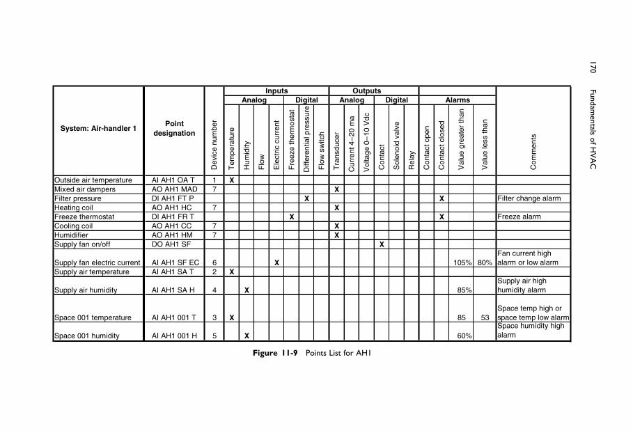
ElsevierUK
Ch11-P373998
3-11-2006
7:40a.m.
Page:170
Trimsize:6.5×
9.5inches
BasalFont:Palatino
Margins:Top:40pt
Gutter:55pt
FontSize:10/11
TextWidth:29pc
Depth:51Lines
170Fundam
entalsofH
VA
C
r ebmu n
eciv eD
erutarepme
T
ytid imu
H
wo lF
tnerruccirtcel
E
tatsom reht
eze erF
er uss erpl ai tnereffiD
hctiws
wolF
r ecud sn arT
am
02–
4tnerruC
cdV
01–
0egatl o
V
tcatnoC
evlavdionelo
S
yaleR
nepotc atnoC
desolc tcat noC
nahtretaerg
eu laV
nah tssel
eulaV
stnem
moC
Outside air temperature AI AH1 OA T 1 XMixed air dampers AO AH1 MAD 7 XFilter pressure DI AH1 FT P X X Filter change alarmHeating coil AO AH1 HC 7 XFreeze thermostat DI AH1 FR T X X Freeze alarmCooling coil AO AH1 CC 7 XHumidifier AO AH1 HM 7 XSupply fan on/off DO AH1 SF X
Supply fan electric current AI AH1 SF EC 6 X 10⁵% 80%Fan current high alarm or low alarm
Supply air temperature AI AH1 SA T 2 X
Supply air humidity AI AH1 SA H 4 X 85%Supply air high humidity alarm
Space 001 temperature AI AH1 001 T 3 X 85 53Space temp high or space temp low alarm
Space 001 humidity AI AH1 001 H 5 X 60%Space humidity high alarm
System: Air-handler 1
Inputs OutputsDigital
Point designation
AlarmsAnalog Digital Analog
Figure 11-9 Points List for AH1

Elsevier UK Ch11-P373998 3-11-2006 7:40a.m. Page:171 Trimsize:6.5×9.5inches
Basal Font:Palatino Margins:Top:40pt Gutter:55pt Font Size:10/11 Text Width:29pc Depth:51 Lines
Controls 171
Freeze Alarm: If the supply air temperature drops below 7 �C, hardwarefreezestat operates, system changes to unoccupied mode and issues“freeze” alarm.
Manual override: If the manual override is sensed, run in “occupied mode”for 3 hours.
System status: 280 seconds after entering “occupied mode” the room temper-ature, supply temperature, and ambient temperature shall be recordedalong with current date and time.
Note that, in this case, the point names are given in full. It really helpsfuture maintenance if a point-naming convention is established and enforced,including having the contractor label every input and every output device withits point name. It also discourages the contractor from accidentally droppinginto the naming convention of the last project!
The convention used here is only an example, chosen to make this text easy tounderstand. Many naming conventions do not include the spaces and manydo not include the AI, AO, DI, and DO, but make the name self-explanatory.For example, instead of AO AH1 CC, they might use AH1 CCV, meaning AH1Cooling Coil Valve.
The column “Device number” refers the contractor to the specification forthe device. In this case, device number 1 is an outdoor air temperature sensor,device number 2 is a duct temperature sensor, and device number 3 is a roomtemperature sensor.
Most of the sequence of operations shown here can be achieved with anycontrol system. Two DDC-specific routines have been included, to aid main-tenance and to help avoid energy waste:
The first DDC-specific routine is to start the fan, leaving all controls alone.The fan will circulate air from the space, so after 280 seconds the sensorsshould have stabilized. The space temperature sensor should record the sametemperature as the supply air temperature, except for the small rise in tem-perature due to fan energy that occurs as the air goes through the fan. Let’ssuppose this rise is normally 0�5 �C on this example system.
One cool day, when the chilled water system is shut down, the operatorchecks the startup temperature rise. It is surprising to note that it is −2 �C, sosomething has gone wrong. It is cool outside, so the outside dampers could beletting in cold air, even when they are controlled to be fully closed. It is alsopossible that the space temperature sensor or supply air temperature sensor isproviding the wrong reading. The operator does not know which is the actualproblem but will probably start by checking the dampers.
The erroneous temperature difference will provide different possibilities forwhat is wrong under different weather conditions, depending on whether thechilled water was available, and whether the temperature difference was posi-tive or negative. The designer can fairly easily work up a written decision treeof possible problems to help the operator. As all the information is available inthe DDC system, the designer can also program the system to work throughthe decision tree and present the operator with the possible problems tocheck.
This level of sophistication is becoming available on factory produced stan-dard products. On larger systems, and for remotely monitored sites, this typeof self-analysis is becoming a valuable feature of high-level DDC systems.However, it is generally not warranted on a small, simple system where theprogramming is being written for that one project.
Elsevier UK Ch11-P373998 3-11-2006 7:40a.m. Page:172 Trimsize:6.5×9.5inches
Basal Font:Palatino Margins:Top:40pt Gutter:55pt Font Size:10/11 Text Width:29pc Depth:51 Lines
172 Fundamentals of HVAC
The second DDC-specific routine is to use a current sensor on one of thecables to the fan to provide a measure of fan current. Our example is a constant-volume system, so the load on the fan will be relatively constant. It will notbe completely constant, since the pressure drop across the filters will rise asthe filters become loaded with dirt. Based on the actual fan current when thesystem is commissioned, a high alarm point and a low alarm point can bechosen. Then, if a bearing starts to fail, the load will typically rise, and this canbe detected before bearing failure and possible destruction of the fan. Also,if the fan is belt driven and the belts slip or break, the fan current will dropsubstantially. This will also be detected. Finally, if the fan starter or motor fails,there will be no motor current, again sensed as low current and alarmed.
These are just two examples of how a small change in the arrangement ofthe DDC controls can provide better control and maintenance.
Now that we have considered the basics of DDC and a sample system, wewill move on to how systems are interconnected and built up into networksserving a whole building or many buildings.
11.6 Architecture and Advantages of Direct DigitalControls
So far we have considered the controls of a single, simple system connectedto a single DDC panel. In many buildings, there will be several systems, oftenwith many more points controlling air-handlers, VAV boxes, heating valves,pumps, boilers, and chillers. Wiring from a single huge DDC panel is not apractical option for two reasons. First, failure of the unit means failure of theentire system, and second, the wiring becomes very extensive and expensive.Instead, the system is broken down into smaller panels that are linked togetheron a communications cable, called a “communications network.”
All of this is fairly simple if the system uses equipment from only onemanufacturer. However, when more than one manufacturer is involved, it isnot as simple. There are three communication issues that create problems. Letus identify them in terms of human communication first.
Languages
The problem is very similar to the problems of human language. In order forpeople from different countries to communicate, interpretation or languagetranslation is required.
Similarly, in the controls world, different companies have worked up differ-ent control languages. The languages differ both in terms of the words and interms of sentence structure. There are two ways of enabling communication sothat one manufacturer’s equipment can communicate with another manufac-turer’s equipment that uses a different programming language. The first is tohave an interpreter, called a “gateway,” between the two units. The second wayis to program an additional, common language into both manufacturers’ units.
Vocabulary and idea complexity
Different people learn different sets of words in the same language. For simple,everyday things, like bread and water, everyone learns the words in each lan-guage. In addition, different people are trained in different skills. Consider, for

Elsevier UK Ch11-P373998 3-11-2006 7:40a.m. Page:173 Trimsize:6.5×9.5inches
Basal Font:Palatino Margins:Top:40pt Gutter:55pt Font Size:10/11 Text Width:29pc Depth:51 Lines
Controls 173
example, when an engineer and an accountant want to discuss the long-termvalue of a project. They can find themselves having great difficulty communi-cating, because they have different vocabularies and different thinking skillsin the same language.
Transmission method and speed
Finally, people send messages over long distances by a variety of methodsat various speeds. For example, consider a letter being faxed to a remoterecipient. It first goes through the fax machine (gateway) to be convertedinto telephone data. The telephone data is routed through various telephoneexchanges (routers) till it reaches the receiving fax machine (gateway) thatconverts the data back into the original text letter.
In addition to the method, there is an issue of speed. Faxing is a quick andeasy way of sending a letter, but if a whole book of text is to be sent, the muchhigher speed available on the Internet is considerably more attractive.
The issues of language, vocabulary and idea complexity, and transmissionmethod and speed are very much the same in DDC systems.
Typically, a DDC panel includes software that provides the sequence of con-trol activities and software for communicating with other panels. The internalsoftware is generally proprietary to each manufacturer, and the communica-tions software can be proprietary or public. There are several good, reliablecommunication languages, called “protocols” for simple information such as“the temperature is 40 �C,” “open to 60%.” The problems arise as soon ashigher level communications, including any form of logic, are required.
In an attempt to eliminate the cost and challenges of no communication orexpensive and limited gateways, ASHRAE produced a communications stan-dard called “BACnet®.” This is a public protocol that is designed to allowcommunication at all levels in a DDC system. It is documented in ASHRAEStandard 135-2004, BACnet®, A Data Communication Protocol for Building Automa-tion and Control Networks.2
BACnet is particularly aimed at facilitating communications between differ-ent vendors’ products at all levels. This allows buyers to have more vendorchoice. It is important to note, though, that while the BACnet standard estab-lishes rules, the designer still has to be very careful, since the number of rulesused by different manufactures can make “BACnet compatible” systems andcomponents unable to communicate. However, with careful specification, onecan obtain units and components from a variety of manufacturers that willcommunicate with each other.
The ability of different manufacturers’ equipment to work together on anetwork is called “interoperability.” To assist in ensuring interoperability andthe use of BACnet, a BACnet interoperability association has been formed totest and certify products.
System Architecture
Let us now consider a DDC system and how it might be arranged—the systemarchitecture. Consider the system illustrated in Figure 11-10.
Across the top of the figure is a high-speed network connecting main stan-dalone panels and the operator terminal. In this example, the standalone panelon the left uses a different communication protocol from the protocols usedby the other two panels and the operator workstation. Therefore, a gateway

Elsevier UK Ch11-P373998 3-11-2006 7:40a.m. Page:174 Trimsize:6.5×9.5inches
Basal Font:Palatino Margins:Top:40pt Gutter:55pt Font Size:10/11 Text Width:29pc Depth:51 Lines
174 Fundamentals of HVAC
Figure 11-10 DDC System
(translator) connects the standalone panel on the left to the network. A “gate-way” is a processor specifically designed to accept specific information in oneprotocol and send out the same information in another protocol.
Note that gateways are specific in terms of “protocol in” and “protocol out”and are often not comprehensive. By “not comprehensive,” we mean that onlyspecifically chosen information, not all information, can be translated (think ofit as a translator with a limited vocabulary and limited intelligence).
The standalone panel on the left has a lower speed network of devicesconnected to it. The sub-panels might be small processors dealing with anair-handling unit, while the “data gathering panel (DGP),” may be simplygathering outside temperature and some room temperatures and transmittingthem to the other panels.
The central standalone panel does all the processing for its branch of thesystem, with remote DGPs to collect inputs and drive outputs. A laptop is tem-porarily connected to one of the DGPs to allow the operator/maintenance staffto interrogate the system. The use of a laptop allows the operator/maintenancestaff to have access to every function on that network branch, but it may notallow access through the standalone panel to the rest of the system.
The right-hand standalone panel is shown as having numerous VAV boxcustom controllers connected to it. These controllers are factory-produced, withfixed software routines built in to them. Programming involves setting set-points and choosing which functions are to be active. These custom controllersare attractive because they are economical, but they are restrictive, in that onlythe pre-written instructions can be used.

Elsevier UK Ch11-P373998 3-11-2006 7:40a.m. Page:175 Trimsize:6.5×9.5inches
Basal Font:Palatino Margins:Top:40pt Gutter:55pt Font Size:10/11 Text Width:29pc Depth:51 Lines
Controls 175
In Figure 11-10 there are a variety of devices in various arrangements withan operator PC as the local human interface. In addition, a phone “modem”is shown allowing communications with the system via a telephone fromanywhere in the world. The modem is a device that converts the digital signalsfrom the PC to audio signals, to allow them to travel on the telephone lines.There are three strikes against modems: they are slow, telephone charges canbe prohibitive, and only one connection can be made to the modem.
These restrictions are now being removed by adding a “web server.” A webserver is another computer! The web server connects between the high-speednetwork and the Internet. It is programmed to take information from the DDCsystem and to present it, on demand, as web pages on the Internet. This enablesanyone who has the appropriate access password to access the system, via theInternet, from anywhere in the world, at no additional cost.
Within the facility, web access allows any PC with web access to be used asan operator station, instead of only specifically designated operator stations.This is much more flexible than having to go to the operator’s terminal to accessthe system. For example, the energy manager can use an office PC to accessenergy data on the machine that is used for normal day-to-day office work.
This chapter has done no more than introduce you to some of the basics andgeneral ideas of DDC. The system has advantages including:
• Increased accuracy and control performance• System flexibility and sophistication that is limited only by your ingenuity
and the available financial resources.• The system ability to store knowledge about the internal behavior over time
and to present this information in ways that assist in energy saving, moni-toring, and improved maintenance.
• Remote access to the entire system to modify software, alter control settings,adjust setpoints and schedules via phone or via the Internet.
• With increased use and the falling price of computer systems in general,DDC is often less expensive than conventional controls.
Then, there are the disadvantages:
• DDC systems are not simple. Qualified maintenance and operations peopleare critical to ongoing success. They must be trained so that they understandhow the system is designed to operate.
• Extending an existing system can be a really frustrating challenge due to thefrequent lack of interoperability between different manufacturers’ productsand even between upgrades of the same manufacturer’s products.
For fairly detailed information on the specification of DDC systems, ASHRAEGuideline 13-2000, Specifying Direct Digital Control System,4 is available.
The Next Step
In Chapter 12 we move on to consider energy conservation. We will reviewthe subject in general before a brief discussion of the ASHRAE/IESNA Standard90.1-2004, Energy Standard for Buildings Except Low-Rise Residential Buildings,and some heat recovery and evaporative cooling energy saving methods.
Elsevier UK Ch11-P373998 3-11-2006 7:40a.m. Page:176 Trimsize:6.5×9.5inches
Basal Font:Palatino Margins:Top:40pt Gutter:55pt Font Size:10/11 Text Width:29pc Depth:51 Lines
176 Fundamentals of HVAC
Summary
Chapter 11 has been an introduction to the ideas behind controls. This is a vastfield and we have only provided a glimpse of the subject. A more technicaland detailed introduction to controls is available as a Self-Directed LearningCourse in this series, Fundamentals of HVAC Control Systems.
The chapter started off with some general discussion on control types: self-powered, electric controls, pneumatic controls, electronic (analog electronic),and direct digital controls. Each of these types has a niche where it is avery good choice but there is a general trend toward DDC controls. We thenconsidered a very simple electric control of a two-element hot water heater toshow how controls can be considered in a logical way. Next we introducedthe control loop and the difference between open loop control (no feedback)and closed loop control (with feedback). The parts of a control loop that youshould be able to identify are: setpoint, sensor, controller, controlled device,and controlled variable.
To illustrate the main issues with modulating controls, we had you imaginepouring water into a glass. The ideas illustrated were
Proportional control is control in which the control action increases in pro-portion to the error from the setpoint
Offset is the change of apparent setpoint as the control action increases in aproportional controller
Gain is the ability of the controller to make a large change in control signalOvershoot is the result of applying too large a control signal and being
unable to reduce it in time to prevent overshooting the control pointSpeed of reaction is the time it takes for the controller to initiate a significant
change
Having considered the standard control loops we went on to consider thefour main types of DDC points:
Digital/Binary Input: a circuit such as a switch closing.Digital/Binary Output: providing power to switch a relay, motor starter, or
two-position control valve.Analog Input: typically a signal from a temperature, pressure, or electric
current sensor.Analog Output: providing a variable signal to a valve, damper, or motor
speed controller, often via a transducer that changes the low powersignal to a pneumatic or electric power source with the necessary powerto drive the valve or damper.
Having introduced the four main point types, we introduced the concept ofusing a point identification scheme. Then we considered a very simple exampleof a sequence of operations which are the logical instructions for the DDCcontroller to execute, to provide the required control. The required informationto specify a DDC system control was then illustrated with a single air handler.The list of control points and schedule of operations is always required, butthe schematic can be omitted, though doing so can lead to misunderstandingsat the time of installation.
In addition to accuracy, a major advantage of DDC is the ability to recorddata and either use it for more intelligent control or as information for theoperator.

Elsevier UK Ch11-P373998 3-11-2006 7:40a.m. Page:177 Trimsize:6.5×9.5inches
Basal Font:Palatino Margins:Top:40pt Gutter:55pt Font Size:10/11 Text Width:29pc Depth:51 Lines
Controls 177
Finally, we considered DDC architecture, introduced BACnet and interop-erability, and listed the pros and cons of DDC.
Bibliography
1. ASHRAE. 1998. Fundamentals of HVAC Control Systems. Atlanta: American Society ofHeating, Refrigerating and Air-Conditioning Engineers, Inc.
2. ASHRAE. 2004. ASHRAE Standard 135-2004, A Data Communication Protocol for Build-ing Automation and Control Networks. Atlanta: American Society of Heating, Refriger-ating and Air-Conditioning Engineers, Inc.
3. ASHRAE. 2004. ANSI/ASHRAE/IESNA Standard 90.1- 2004, Energy Standard for Build-ings Except Low-Rise Residential Buildings. Atlanta: American Society of Heating,Refrigerating and Air-Conditioning Engineers, Inc.
4. ASHRAE. 2000. ASHRAE Guideline 13-2000, Specifying Direct Digital Controls Systems.Atlanta: American Society of Heating, Refrigerating and Air-Conditioning Engi-neers, Inc.

Elsevier UK Ch12-P373998 3-11-2006 7:41a.m. Page:178 Trimsize:6.5×9.5inches
Basal Font:Palatino Margins:Top:40pt Gutter:55pt Font Size:10/11 Text Width:29pc Depth:51 Lines
Chapter 12
Energy Conservation Measures
Contents of Chapter 12
InstructionsObjectives of Chapter 1212.1 Introduction12.2 Energy Considerations For Buildings12.3 ASHRAE/IESNA Standard 90.1-200412.4 Heat Recovery12.5 Air-Side and Water-Side Economizers12.6 Evaporative Cooling12.7 Control of Building PressureThe Final StepSummaryBibliography
Instructions
Read the material of Chapter 12. Re-read the parts of the chapter that areemphasized in the summary and memorize important definitions.
Objectives of Chapter 12
There are three primary objectives in Chapter 12:First we will introduce some basic ideas about energy conservation.The second objective is to introduce ASHRAE/IESNA Standard 90.1-2004,
Energy Standard for Buildings Except Low-Rise Residential Buildings1 (Standard90.1). This standard, produced cooperatively by ASHRAE and the IlluminatingEngineering Society of North America, is becoming the minimum standard fornew buildings in the United States.
Lastly, we are going to look at four ways that HVAC systems can be designedto use less energy.
After studying the chapter, you should be able to:
Explain energy conservation and some basic ways of thinking about it.Describe, generally, the contents of Standard 90.1.Describe the equipment and operation of the heat wheel, heat pipe, and
runaround methods of heat recovery.Describe the process of evaporative cooling and be able to provide examples
of uses.Explain the significance of building pressure.
Elsevier UK Ch12-P373998 3-11-2006 7:41a.m. Page:179 Trimsize:6.5×9.5inches
Basal Font:Palatino Margins:Top:40pt Gutter:55pt Font Size:10/11 Text Width:29pc Depth:51 Lines
Energy Conservation Measures 179
12.1 Introduction
During this course we have mentioned and discussed the differences betweeninitial cost and cost-in-use that are relevant to various types of equipment.In many instances, the savings on the initial cost of equipment is squanderedbecause the equipment is more expensive to run, due to excessive energy coststhat are incurred over the life of the building.
The objective of energy conservation is to use less energy. This is accom-plished by various methods, including recycling energy where useful. Energyconservation should be part of the entire life cycle of a building: it should be aconsideration during the initial conception of a building, through its construc-tion, during the operation and maintenance of the building throughout its life,and even in deconstruction.
It is important for everyone who participates in the design, operation, andmaintenance of the building to realize that, however energy efficient the systemas initially designed and installed, the energy efficiency will degrade unless itis operated correctly and deliberately maintained.
In order to improve the energy performance of buildings and provide abenchmark for comparison ASHRAE/IESNA has issued Standard 90.1, EnergyStandard for Buildings Except Low-Rise Residential Buildings. This standard setsout minimum criteria for the building construction and mechanical and elec-trical equipment in the building and we will discuss it later in the chapter.
12.2 Energy Considerations For Buildings
The energy consumption of a building is determined from the very first designdecisions through to final demolition.
Conception and design
In the very beginning of the design process, many architectural choices canbe made to significantly increase, or decrease, the energy consumption of abuilding. For example, large unshaded windows that face the afternoon suncan greatly increase the cooling load. Alternatively, the same windows, facingnorth produce a relatively small cooling load.
It is at the early design stage that the mechanical designer should becomeseriously involved in the building design as a whole. Historically, the architectwould design the building, and then send a set of plans to the mechanicaldesigner to design the HVAC. This model does not work well to produceenergy-efficient buildings, because many early design choices can facilitateenergy conserving design or make them totally impossible or uneconomic.
Consider this example:
In cold climates, a perimeter hot water heating system is often used to offsetthe heating losses through the wall and windows. Because modern windowsare available with insulation values that approach the insulation value oftraditional walls, if the architectural design specifies walls and windows withhigher insulation values, the perimeter heating system requirements couldbe avoided. However, this is a suggestion that would typically be made bythe mechanical designer, and the choice can only be made very early in theproject. If the mechanical designer suggests a more energy efficient design, this

Elsevier UK Ch12-P373998 3-11-2006 7:41a.m. Page:180 Trimsize:6.5×9.5inches
Basal Font:Palatino Margins:Top:40pt Gutter:55pt Font Size:10/11 Text Width:29pc Depth:51 Lines
180 Fundamentals of HVAC
could have a negative impact on the mechanical design fee. Why? Buildingowners often contract with the design team members for a fee that is based ona percentage of their individual portion of the building cost. In the examplejust given, the fee for the mechanical designers would include a percentageof the cost of the perimeter heating system. As a result, if the mechanicaldesigners suggest that the perimeter heating be omitted in favor of higherpriced windows, they could be forfeiting a substantial portion of their fee.Hardly an incentive to the engineer to suggest the idea!
Since this method of calculating the mechanical design fee does not encour-age energy conservation, what other alternatives are available?
Imagine an alternative fee structure, where the total design fee for themechanical design would be calculated as a percentage of the cost of the com-pleted building, rather than of the specific mechanical design elements. Then,the mechanical designers could make design suggestions that would not havea negative impact on their design fees. Furthermore, imagine what wouldhappen if the contract also specified that an objective of the building designincluded energy savings, and provided the entire design team with financialbonuses based on achieving the energy savings. Then the design team wouldhave an incentive to spend time on designing energy efficient buildings!
How could this bonus incentive be structured? Consider what would happenif the bonus represented half the energy savings that were achieved during thefirst five years after the building was completed (based on the estimated energycosts for a conventional building design). In this case, the design team wouldhave an incentive to design for maximum energy savings. The result wouldbe that the operating expense for the owner would be reduced by half theenergy cost reduction during the first five years, and all future energy-relatedsavings after that. In this scenario, the owner could save money by setting upthe contract to encourage desired behavior! Notice that there is not necessarilyany additional capital cost to the owner, only the likelihood of operational costsavings: a huge return based only on some contract wording.
In case you are thinking it would never work, you should know that manyowners are willing to contract to have energy conservation specialists comeback, after construction is completed, and to pay them a significant fee, inaddition to retrofit costs, to fix what could have been achieved as part of theoriginal design at a fraction of the cost. We will discuss energy conservationthat can be achieved through retrofit in the section entitled: “Turn it in.”
Construction
The best possible building plans can be made a mockery by poor construction.If windows and doors are not sealed to the walls, or if insulation is installedunevenly and with gaps, the air-leakage can be costly in terms of both energyand building deterioration. The mechanical plant must be installed and setworking correctly. Many systems are surprisingly robust, and gross errors ininstallation can go undetected, making the building less energy efficient—andless comfortable—than it was designed to be.
Operation
If the staff does not know how a system is meant to work, there is a veryhigh probability that they will operate it differently and, more than likely,

Elsevier UK Ch12-P373998 3-11-2006 7:41a.m. Page:181 Trimsize:6.5×9.5inches
Basal Font:Palatino Margins:Top:40pt Gutter:55pt Font Size:10/11 Text Width:29pc Depth:51 Lines
Energy Conservation Measures 181
not as efficiently. It is really important that staff be taught how the systemsare designed to work and provided with clear, easy to understand, writteninstructions for later reference. A pile of manufacturer’s leaflets may lookpretty but it does not explain how all the bits are meant to work together.
Maintenance
With limited maintenance, even the best equipment will falter and fail. Controlsdo not hold their calibration and work indefinitely. Control linkages wear out;damper seals lose their flexibility; cooling towers fill up with dust; the filldegenerates; and chiller tubes get fouled with a coating which reduces theirheat transfer performance. The list of maintenance requirements is very long,but critical for maintaining energy-efficient building performance.
Three ways to save energy
The mantra of energy savings is: Turn it off. Turn it down. Turn it in.
1. Turn it offThis is the simplest, and almost always the least expensive method to imple-ment, and it has the highest saving. If a service is not required, can it be turnedoff? There are usually several alternatives that can be considered to shortenthe running time to the minimum.
Opportunities to “Turn it off” can be found at the design phase and at theoperational phase of a building’s life cycle.
Let us take a simple example of stairway lighting in a mild climate. For thisexample, we will ignore any local issues of safety or legislation:
A four-story apartment building has stairs for access. If the stairs are fullyenclosed, the lights must be “on” all the time for people to see their way upand down the stairs.
The first alternative for energy savings can be identified early in the designphase of the building. Designing the stairs with large windows allows thelights to be turned off during daylight hours. The light switching can easily bedone with an astronomical clock, or better still, a photocell. The astronomicalclock allows for the changing lengths of the day, while the photocell sensesthe light level and switches on and off at a preset light level.
At both the design and the operation phases of the building’s life cycle, asecond savings opportunity exists. To discover it, consider asking the question:“What is the objective of having the lights on?” The lights are to provideillumination for people to go up and down the stairs. The next question is,“Is there a way to provide illumination when it is required, and yet not havethe lights on when it is not required?” Several solutions come to mind. A lowtech solution could be the installation of a pneumatic push-button timer switchat each level. Then, people entering the stairwell could push the button andturn the lights on for, say, ten minutes. The advantage is that, now, we have asimple system that provides the required service when it is required. However,there is an education requirement with a system like this. People need to beshown where the light switch is located. And they need to be taught that,even if the stairwell has been illuminated because an earlier person turned

Elsevier UK Ch12-P373998 3-11-2006 7:41a.m. Page:182 Trimsize:6.5×9.5inches
Basal Font:Palatino Margins:Top:40pt Gutter:55pt Font Size:10/11 Text Width:29pc Depth:51 Lines
182 Fundamentals of HVAC
the switch “on,” they still have to reactivate the switch, in order to providecontinuous illumination while they are in the stairwell. For example, if oneperson has entered the stairwell and depressed the switch, the stairwell willbe illuminate for ten minutes. Nine minutes later, a second person enters thestairwell and, because the light is “on,” does not look for a switch. While thatsecond person is in the stairwell, the lights will go off, leaving that person inthe dark. As a result, graphics-based signage would be required, to manageissues based on language and reading skills. To alleviate these signage issues,the switch could be wired to detect the opening of the lobby door, or motiondetectors could be used to turn the lights “on.”
The above example illustrates how a building design choice—in this casewindows—allowed a substantial reduction in operating hours. Then thinkingabout “What is the objective?” allowed a further, large, reduction in operat-ing hours.
Determining design parameters based on a requirement to “turn it off” mayseem extreme, but it is the norm in many parts of the world. You wouldprobably be surprised at how many opportunities you could find in your ownexperiences where things could be turned off, and energy could be saved, ifthe focus was on providing only what is needed.
Now let’s go on to the second approach, which tends to be more complicated,and therefore more costly, to work out and implement.
2. Turn it down“Turn it down” means reducing the amount of heating, cooling, or otherprocess while still providing the required service. In Chapter 4, when wecovered CO2 control of ventilation air, we discussed the idea of only providingthe required amount of a service at the time it is needed. As you recall, CO2was used as a surrogate (indicator) for assessing the room population anddeciding how much outside air was required for the current occupants. UsingCO2 as a surrogate allowed the amount of outside air to be turned down whenthe room population was low.
There are numerous examples of using “turn it down” as an energy conser-vation tool. Two that are commonly implemented include:
Heating reset: In Chapter 8 we discussed resetting the heating watertemperature down, as the load drops. This reduces piping heat losses andimproves control. However, on a variable speed pumping system, lowering thewater temperature increases water volume required and so increases pumpingpower. The issue is finding the best balance between temperature reset andpumping power.
Chilled water temperature reset: The chilled water system is designed forthe hottest and most humid afternoons that happen a few times a year. Therest of the time the chilled water system is not running to full capacity. Exceptin a very humid climate, where dehumidification is always a challenge, thechilled water temperature can probably be reset up a degree or two or more.This improves chiller performance and generally saves energy.
3. Turn it in“Turn it in” means “replace with a new one.” This is the third way of savingenergy. It is almost always the most difficult to justify, since it is the mostcostly. For example, your building may have a forty-year-old boiler with aseasonal efficiency of only 50%. A modern boiler might raise the seasonal

Elsevier UK Ch12-P373998 3-11-2006 7:41a.m. Page:183 Trimsize:6.5×9.5inches
Basal Font:Palatino Margins:Top:40pt Gutter:55pt Font Size:10/11 Text Width:29pc Depth:51 Lines
Energy Conservation Measures 183
efficiency to 70% and provide a fuel saving of 28%. Although the percentagesaving is substantial, it can be frustrating to find that it would take 12 yearsto pay for a new boiler out of the savings. Typically, a 12-year payback is toolong for the financial officer to accept.
It almost never pays in energy savings to replace building fabric. For exam-ple, replacing single pane windows with double or triple pane or replacing aroof with a much better insulated roof usually have energy savings that payfor the work in 30 years or more. However, if the windows are going to bereplaced because they are old and the frames have rotted, then it is almostalways worth spending a bit extra on a higher energy-efficient unit. Here, oneis comparing the extra cost of better windows against the extra energy savings,and it is usually an attractive investment.
While it almost never pays to replace building fabric, we should also notethat it is usually economically worthwhile to repair the building fabric, partic-ularly where there are air holes. For example, many industrial buildings haveconcrete block walls up to the roof. Over time, the block walls may well dropa bit, leaving a gap between wall and roof. Plugging this gap with expand-ing foam is a simple task and can reduce the uncontrolled flow of air into,and out of, the building. In a humid climate, this can substantially reduce thedehumidification load; in a cool climate, it could provide substantial heatingenergy saving.
It is exactly the same for the plant. The boiler may be 40 years old but it willwork better if the burner is regularly serviced.
Chillers are another area of consideration. Due to the regulated phase-outof CFC refrigerants, many owners are being forced to consider chiller replace-ment. If the chiller is to be replaced anyways, it is worth taking the time tocalculate the extra savings that are available from a high efficiency unit ascompared to the extra cost for the unit. It is highly likely that the differencein cost for the high efficiency chiller will have a speedy payback in energysavings.
Having introduced three ways of saving energy—Turn it off, Turn it down,Turn it in—let’s move on to a standard that sets minimum requirements forenergy saving in new buildings and major renovations.
12.3 ASHRAE/IESNA Standard 90.1-2004
ASHRAE and the Illuminating Society of North America (IESNA) wroteANSI/ASHRAE/IESNA Standard 90.1, Energy Standard for Buildings ExceptLow-Rise Residential Buildings (Standard 90.1) as a joint venture. The Standardis on “continuous maintenance.” This means that addenda to the Standard areconsidered, developed, sent for public review and revision and then adoptedby ASHRAE and then ANSI. These addenda then become part of the Stan-dard. This is a continuous process, rather than one triggered by date. Everythree years the Standard is reprinted with all addenda incorporated. The lat-est printed edition is 2004, which was used for this text. There is a detailed,well-illustrated, and explanatory companion document, 90.1 User’s Manual,ANSI/ASHRAE/IESNA Standard 90.1-2004, Energy Standard for Buildings ExceptLow-Rise Residential Buildings.2
The stated purpose of the Standard is “to provide minimum requirementsfor energy-efficient design of buildings except low-rise residential buildings.”

Elsevier UK Ch12-P373998 3-11-2006 7:41a.m. Page:184 Trimsize:6.5×9.5inches
Basal Font:Palatino Margins:Top:40pt Gutter:55pt Font Size:10/11 Text Width:29pc Depth:51 Lines
184 Fundamentals of HVAC
It is a minimum standard and it defines two methods for achieving energyefficient design:
1. Complying with the “Prescriptive and Performance Requirements”2. Complying with the “Energy Cost Budget Method”
The Standard thus serves as a minimum for the use of building code officialsas well as providing a solid baseline from which to compare considerably moreenergy efficient buildings.
Prescriptive and Performance Requirements
The Standard is divided into sections that often relate to different membersof the design team. The first section of the Standard is the “Administrationand Enforcement” section, to help designers and code officials. It then hassix prescriptive sections that define the performance of the components of thebuilding. Finally, it concludes with a calculation method, the “Energy CostBudget Method” section.
The following is a brief introduction to the sections.
Standard 90.1 Section 5: Building Envelope
Typically, this section is used by architects to guide their design choices aboutthe building fabric: the roofs, walls, floors, doors and fenestration (windows).
The objective of the Standard is to ensure that design choices reflectthe requirements of different climate types to produce buildings that areboth energy-efficient and cost-effective. Therefore, for example, the insulationrequirements are more demanding in the colder climates.
The Standard divides climates into eight temperature bands with some fur-ther division depending on whether the climate is humid, dry or coastal. Thetemperature bands range from the continuously hot, with no heating demands,through to the sub-artic continuous heating with no cooling requirements. Thedesigner chooses the temperature band relating to the building location, and,in a single table finds the thermal transmission requirements for the buildingfabric.
The Standard often requires slightly higher performance for residentialbuildings, since they are generally in operation 24 hours of every day. In com-parison, many non-residential buildings are in full operation for less than halfthe hours in a week.
One of the major problem areas of modern buildings is the sealing thebuilding envelope. The building envelope includes the entire perimeter ofthe building: the windows, doors, walls, and the roof. The allowable leakagearound most factory-produced windows and doors is limited to a specific testvalue. Unfortunately, there is no overall leakage standard for buildings, sothe actual thermal performance may vary considerably depending on howmeticulous the construction sealing is carried out.
The Standard allows some trade-off between the various sections of thebuilding envelope as long as the required overall envelope performance ismaintained.
Standard 90.1 Section 6: Heating, Ventilating, and Air Conditioning
Typically, this section is used by mechanical designers to guide their designchoices about the HVAC equipment and operational specifications.
Elsevier UK Ch12-P373998 3-11-2006 7:41a.m. Page:185 Trimsize:6.5×9.5inches
Basal Font:Palatino Margins:Top:40pt Gutter:55pt Font Size:10/11 Text Width:29pc Depth:51 Lines
Energy Conservation Measures 185
For buildings of one or two floors and less than 2�300 m2 there is a simplifiedapproach to HVAC design using single-zone air-conditioning units servingsingle zones. The Standard includes a number of simple requirements thatguide equipment choice and operation. It also provides tables of requiredoperating efficiencies. This enables designers for many smaller buildings toquickly choose packaged equipment from a catalogue based on the calculatedloads and fairly simple performance criteria.
For larger buildings and multi-zone systems there are numerous require-ments for minimum equipment efficiencies and control strategies. Minimumcooling equipment performance is defined in two ways: Coefficient of Perfor-mance, “COP”; and Integrated Part-Load Value, “IPLV.”
COP, Coefficient Of Performance, is the ratio of heat removal to energyinput in consistent units. For air-cooled chillers of all sizes, the minimumrequirement is COP of 2.8. This means that the chillers must provide 2.8 kWof cooling capacity for every 1 kW of input power. In contrast, water-cooledchillers are much more efficient: a centrifugal water-cooled chiller under528 kW has a required minimum COP of 4.45, and a chiller that is over 1055 kWhas a required COP of 6.1. The large water-cooled centrifugal chiller has overtwice the cooling capacity per input watt of the air-cooled machine.
In Chapter 10.1, we discussed the statement that “big plant is more efficient.”In the case of chillers, this is very true. Unfortunately, COP efficiency is not theonly relevant consideration. Other energy costs for the central plant includethe energy for pumping the chilled water to end use and the condenser waterto the cooling tower. In addition, the chilled water distribution-pipe heat gainsmust be deducted from the useful plant cooling capacity.
In addition to the other energy inputs, many central plant units spend a sig-nificant part of their operating life operating at below full-load. To ensure thatthe poor part-load performance does not seriously impact overall performance,a minimum Integrated Part-Load Value, IPLV is specified for larger equip-ment. IPLV, is a weighted average value of COP based on full and part loadperformance and is used instead of COP on larger electrically-driven coolers.
Having defined minimum equipment performance, the Standard then goeson to establish rules about controls and installation including insulation,system balancing, commissioning, and user operating manuals, to ensure min-imum equipment utilization efficiency. We have already discussed some of thecontrols requirements in the previous chapter.
Standard 90.1 Section 7: Service Water Heating
The section on service water heating covers hot water for domestic washingand laundry, similar commercial uses, and swimming pools. The requirementscover heater efficiency, standby losses, distribution-piping design, insulation,and control requirements.
Standard 90.1 Section 9: Lighting
On average, in the USA, buildings use about 35% of their total energy forlighting. This provides a big opportunity for savings. The Standard allows aspecific number of Watts per square meter, W/m2, however, the designer isgiven a certain amount of leeway in the calculations: The allowed W/m2 canbe calculated on the basis of type of building or on a room-by-room basis. TheStandard allows trading between non-decorative areas and between lighting

Elsevier UK Ch12-P373998 3-11-2006 7:41a.m. Page:186 Trimsize:6.5×9.5inches
Basal Font:Palatino Margins:Top:40pt Gutter:55pt Font Size:10/11 Text Width:29pc Depth:51 Lines
186 Fundamentals of HVAC
and HVAC, as long as the net energy cost through the year is not increasedabove the prescribed allowance.
The Standard recognizes variation in use of the same type of space in differ-ent types of buildings. So, for example, corridors generally have an allowanceof 5 W/m2 but, for hospitals, this allowance is raised to 11 W/m2.
Standard 90.1 Section 11: Energy-Cost Budget Method
The energy-cost budget is a way to allow designers to have the flexibility todesign the building according to their needs, as long as it does not cost more inenergy than the Standard permits. To use the Energy-Cost Budget Method, thedesign team is instructed to calculate the energy-cost budget for a prescriptivebuilding and equipment, then to compare that to the cost of the energy thatis required by the building fabric and equipment that the design team hasselected.
The Energy-Cost Budget, ECB, requires the use of hour-by-hour buildingenergy analysis software. No particular software is specified, but software per-formance is mandated. Local utility rates are used in the simulation. The build-ing has to be analyzed, using the prescribed building envelope and equipmentefficiencies, to obtain the ‘energy-cost budget’ and again with actual envelopeand equipment. Compliance is achieved when the ‘design energy-cost’ doesnot exceed the ‘energy-cost budget.’
Many organizations, and energy reduction programs, like Leadership inEnergy and Environmental Design, LEED, are interested in building to ahigher energy efficient standard than the minimum. For example, LEED,encourages buildings that are designed to have a lower design energy costthan the same building would have had if it had been designed using theprescriptive and performance requirements. Designers can aim to design abuilding with an energy cost that is some specific percentage lower than theenergy cost for a minimum standard design. As an example, the LEED pro-gram gives increasing acknowledgement for design energy costs from 15% to60% below the Standard 90.1 prescriptive building energy costs.
Finally, others are concerned about the relative energy consumption asagainst energy cost. To provide a consistent method of measuring and con-trolling energy consumption, an informative, non-mandatory part, of the Stan-dard, Appendix G, is included. This appendix is written to assist in comparinghighly energy-efficient building designs based on energy efficiency instead ofenergy cost.
If you become involved in using Standard 90.1, remember that the UserManual provides a clear, easy-to-follow explanation of how to use and applythe Standard.
12.4 Heat Recovery
When designing to comply with the Standard, designers can minimize energyuse by reducing the energy requirements of a building, and/or by energyrecovery. During design, always aim first to minimize energy use before con-sidering energy recovery. The reason is that heat recovery is almost alwaysinvolved with “low-grade heat.” Low-grade heat is heat that is at a tem-perature relatively close to the temperature at which it can be used at all.Low-grade heat requires oversized heat transfer surfaces and can often only

Elsevier UK Ch12-P373998 3-11-2006 7:41a.m. Page:187 Trimsize:6.5×9.5inches
Basal Font:Palatino Margins:Top:40pt Gutter:55pt Font Size:10/11 Text Width:29pc Depth:51 Lines
Energy Conservation Measures 187
fill a part of the load. For example, the condenser water from a chiller at 35 �Ccan be used to preheat domestic service water to 32 �C but no hotter. This isa valuable contribution, but it does not do the whole task, since 60 �C is thetypical requirement.
There are cases where systems can be deliberately chosen to integrate withlow heat sources. A good example of this is the use of condensing boilerswith radiant floor heating systems. The condensing boiler is a boiler with anadditional flue gas heat recovery section. In this additional flue gas coolingsection, the water vapor in the flue gas is condensed, causing it to give up itslatent heat. This increases the boiler efficiency from a maximum of about 85%,with a flow temperature of 82 �C, to about 95% with a 40 �C flow temperature.Since radiant flooring operates at low water temperature, the condensing boileris an excellent match for the radiant floor. Note that condensing only begins tooccur below 57 �C, so buying a condensing boiler and running it near 57 �C willreduce the boiler efficiency since it will not condense the flue gas water vapor.
Energy Recovery Coils: Run-Around Coils
One way to achieve energy recovery is with run-around energy recovery coils.A typical run-around coil arrangement is shown in Figure 12-1.
In summer, the conditioned exhaust air cools the fluid in the exhaust air coil.This fluid is then pumped over to the supply air coil to pre-cool the incomingoutside air.
In winter the heat transfer works the other way: the warm exhaust air heatsthe fluid in the exhaust air coil, which is then pumped over to the supply aircoil to heat the cold incoming air.
Figure 12-1 Run-Around Energy Recovery Coils
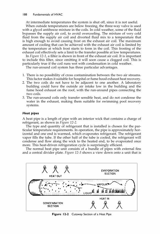
Elsevier UK Ch12-P373998 3-11-2006 7:41a.m. Page:188 Trimsize:6.5×9.5inches
Basal Font:Palatino Margins:Top:40pt Gutter:55pt Font Size:10/11 Text Width:29pc Depth:51 Lines
188 Fundamentals of HVAC
At intermediate temperatures the system is shut off, since it is not useful.When outside temperatures are below freezing, the three-way valve is used
with a glycol antifreeze mixture in the coils. In cold weather, some of the fluidbypasses the supply air coil, to avoid overcooling. The mixture of very coldfluid from the supply air coil and diverted fluid mix to a temperature thatis high enough to avoid causing frost on the exhaust air coil. The maximumamount of cooling that can be achieved with the exhaust air coil is limited bythe temperature at which frost starts to form in the coil. This frosting of theexhaust coil effectively sets a limit to the transfer possible at low temperatures.
In Figure 12-1, a filter is shown in front of the exhaust air coil. It is importantto include this filter, since omitting it will soon cause a clogged coil. This isparticularly true if the coil runs wet with condensation in cold weather.
The run-around coil system has three particular advantages.
1. There is no possibility of cross contamination between the two air streams.This factor makes it suitable for hospital or fume hood exhaust heat recovery.
2. The two coils do not have to be adjacent to one another. A laboratorybuilding could have the outside air intake low in the building and thefume hood exhaust on the roof, with the run-around pipes connecting thetwo coils.
3. The run-around coils only transfer sensible heat, and do not condense thewater in the exhaust, making them suitable for swimming pool recoverysystems.
Heat pipes
A heat pipe is a length of pipe with an interior wick that contains a charge ofrefrigerant, as shown in Figure 12-2.
The type and quantity of refrigerant that is installed is chosen for the par-ticular temperature requirements. In operation, the pipe is approximately hor-izontal and one end is warmed, which evaporates refrigerant. The refrigerantvapor fills the tube. If the other half of the tube is cooled, the refrigerant willcondense and flow along the wick to the heated end, to be evaporated oncemore. This heat-driven refrigeration cycle is surprisingly efficient.
The normal heat pipe unit consists of a bundle of pipes with external finsand a central divider plate. Figure 12-3 shows a view down onto a unit that is
Figure 12-2 Cutaway Section of a Heat Pipe

Elsevier UK Ch12-P373998 3-11-2006 7:41a.m. Page:189 Trimsize:6.5×9.5inches
Basal Font:Palatino Margins:Top:40pt Gutter:55pt Font Size:10/11 Text Width:29pc Depth:51 Lines
Energy Conservation Measures 189
Figure 12-3 Heat Pipe Assembly in Exhaust and Outside Air Entry
mounted in the relief and intake air streams to an air-handling unit. Flexibleconnections are shown which facilitate the tipping. To adjust the heat transfer,one end or the other end of the tubes would be lifted.
The outside air is cold as it comes in over the warm coil. This warms theair, and the tube is cooled. The cooled refrigerant inside condenses, giving upits latent heat, which heats the air. The re-condensed refrigerant wicks acrossto the exhaust side and then absorbs heat from the exhaust air. This heatevaporates the refrigerant back into a vapor which fills the pipe, and is againavailable to warm the cold outside air.
The usual heat-pipe unit must be approximately horizontal to work well. Astandard way to reduce the heat transfer is to tilt the evaporator (cold) endup a few degrees. This tilt control first reduces, and then halts, the flow ofrefrigerant to the evaporator end, and the process stops.
Figure 12-3 was based on winter operation. In summer, the unit only has tobe tilted to work the other way and cool the incoming outside air as it heatsthe outgoing exhaust air.
The unit is designed as a sensible heat transfer device, though allowingcondensation to occur on the cold end can transfer worthwhile latent heat.Effectiveness ratings range up to 80% with 14 rows of tubes. However, eachadditional row contributes proportionally less to the overall performance. Asa result, the economic choice is ten or fewer rows.
A major advantage of the units is very low cross-contamination.
Desiccant Wheels
Desiccants are chemicals that are quick to pick up heat and moisture, andquick to give them up again if exposed to a cooler, drier atmosphere. A matrix,as indicated on the left of Figure 12-4, may be coated with such a chemical andmade up into a wheel several centimeters thick. In use, the supply air is ductedthrough one half of the wheel and the exhaust air through the other half.
Let us suppose it is a hot summer day, so the exhaust is cooler and drierthan the supply of outside air. The chemical coating in the section of the coil in

Elsevier UK Ch12-P373998 3-11-2006 7:41a.m. Page:190 Trimsize:6.5×9.5inches
Basal Font:Palatino Margins:Top:40pt Gutter:55pt Font Size:10/11 Text Width:29pc Depth:51 Lines
190 Fundamentals of HVAC
Figure 12-4 Desiccant Wheel Matrix and Operation
the exhaust stream becomes relatively cool and dry. Now the wheel is slowlyrotated and the cool, dry section moves into the incoming hot, humid air,drying and cooling the air. Similarly, a section is moving from hot and humidinto cool and dry, where it gives up moisture and becomes cooler.
The wheel speed, a few revolutions per minute, is adjusted to maximizethe transfer of heat and moisture. Control of wheel speed to truly maximizesavings is a complex issue, since the transfers of sensible and latent heat donot vary in direct relation to each other.
The depth of the wheel is filled with exhaust air as it passes into the supplyair stream, so there is some cross-contamination. There are ways of minimiz-ing this cross-contamination, but it cannot be eliminated. In most comfortsituations, the cross-contamination in a well-made unit is quite acceptable.
12.5 Air-Side and Water-Side Economizers
Air-Side Economizers
In the previous chapters, you have been introduced to the air-side economizeron air-handling units. It is the mixing arrangement that allows up to 100%outside air to be drawn in and relieved in order to take advantage of cooloutside air, providing “free cooling.” Nothing is free! The air-side economizerequipment costs extra to purchase, there are more components to maintain,and, depending on the climate, the hours when the economizer is actuallysaving cooling energy may be very limited. In climates that are warm andhumid, the number of hours when the outside air has a lower enthalpy thanthe return air enthalpy may be very few. Thus, Standard 90.1 does not requireair-side economizers in most of Florida.
One critical issue with economizers is that their controls must be integratedwith the mechanical cooling. This prevents the economizer from increasing themechanical refrigeration load.
Standard 90.1 has very specific requirements on the control of economizersand, in particular, prohibits the use of mixed air control for economizers onsystems that serve more than one zone. Instead, the Standard requires that asupply air thermostat be used to control the cooling coil and economizer. Thiscontrol method works well as long as the chilled water valve and, if there isone, the heating valve, close fully. If the valves do not close, due to being wornor incorrectly set up, it is possible for the system to use much more energythan expected. Therefore, when this control method is used, it is importantthat the system be maintained, or that a control sequence be included that willindicate that one of the valves is not closing correctly. This control sequencewas discussed in Section 11.5.

Elsevier UK Ch12-P373998 3-11-2006 7:41a.m. Page:191 Trimsize:6.5×9.5inches
Basal Font:Palatino Margins:Top:40pt Gutter:55pt Font Size:10/11 Text Width:29pc Depth:51 Lines
Energy Conservation Measures 191
Advantages of the air-side economizer
• A low air pressure drop.• Substantial mechanical-cooling energy savings.• Reduced water usage in cooling tower systems.
Disadvantages of the air-side economizer
• Extra capital cost for the 100% intake and relief air equipment, which includesa return fan on larger systems.
• A higher ongoing electrical operating expense.• A potential requirement for additional humidification during winter
operation.
Water-Side Economizers
The water-side economizer consists of a water-cooled coil, located in the airstream just before the mechanical-cooling coil. The coil can be supplied withwater directly from the cooling tower or via a plate heat exchanger. If thewater is supplied directly from the tower, the water treatment and cleaningprocess must be of a high standard, to ensure that the valves and coil do notclog up with dirt. If a heat exchanger is used, there is the additional cost ofthe exchanger, and the heat transfer will be less efficient, since there has to bea temperature rise across the exchanger for it to work.
There are several possible arrangements, depending on the particular equip-ment and sizes. One example for packaged units is shown in Figure 12-5. Thethree-port valve determines how much of the tower water flows through theeconomizer coil, and the two-port valve determines how much water bypassesthe condenser to avoid the condenser being overcooled.
Note that the three-port valve can be replaced with two two-port valves, asshown in the detail. The valves would be sequenced so that, as one opens, the
Figure 12-5 Water-Side Economizer and Alternate Use of Two-Port Valves
Elsevier UK Ch12-P373998 3-11-2006 7:41a.m. Page:192 Trimsize:6.5×9.5inches
Basal Font:Palatino Margins:Top:40pt Gutter:55pt Font Size:10/11 Text Width:29pc Depth:51 Lines
192 Fundamentals of HVAC
other closes, to provide the same effect as the mixing valve, but often at lowercost in small sizes.
The “head pressure” is the pressure in the refrigeration condenser. If thehead pressure falls below the required pressure, the valve is opened to reducewater flow through the condenser. On cool days, when the tower producesvery cold water, the valve will stay open, since adequate cooling is providedat well below full design flow.
Advantages of water-side economizers
• Water-side economizers reduce compressor energy requirements by pre-cooling the air.
• Unlike air-side economizers, which need full-sized intake and relief ducts for100% outside air entry or for 100% exhaust, water-side economizers simplyrequire space for two pipes.
• Unlike the air-side economizer, the water-side economizer does not lowerthe humidity in winter, saving on possible humidification costs.
Disadvantages of a water-side economizer
• Higher resistance to airflow, therefore higher fan energy costs.• Increased tower operation with consequent reduction in tower life span.• Increased water and chemicals cost.
12.6 Evaporative Cooling
You have been introduced to the idea of evaporative cooling several times sofar in this course. In Chapter 2 the process of using direct evaporation wasintroduced in connection with the psychrometric chart.
Direct Evaporative Cooling
The direct evaporative cooler simply evaporates moisture into the air, reducingthe temperature at approximately constant enthalpy. In a hot dry climate thisprocess may often be enough to provide comfortable conditions for people.
In medium to wet climates, the increase in moisture content is frequentlynot acceptable for sedentary human comfort but is considered acceptable forhigh effort work places and is ideal for some operations, such as green-houses.
Indirect Evaporative Cooling
An indirect evaporative cooler uses evaporation to cool a surface, such asa coil, that is then used to cool the incoming air. The indirect evaporativecooler, which reduces both temperature and enthalpy, can be very effectivein all but the most extreme conditions. The two processes are shown on thepsychrometric chart, Figure 12-6.
A previous figure, Figure 12-5 showed the indirect cooler as the “water-side economizer,” located before the mechanical cooling coil. That is just onearrangement of two-stage cooling.
Figure 12-7 shows an alternative to this arrangement.

Elsevier UK Ch12-P373998 3-11-2006 7:41a.m. Page:193 Trimsize:6.5×9.5inches
Basal Font:Palatino Margins:Top:40pt Gutter:55pt Font Size:10/11 Text Width:29pc Depth:51 Lines
Energy Conservation Measures 193
Figure 12-6 Psychrometric Chart Showing Direct and Indirect Evaporative Cooling
Figure 12-7 Indirect Evaporative Intake Cooler
In this indirect evaporative-intake cooler, water flows down the outside ofthe air intake passages. As it flows down, outside air is drawn up over thewater, causing evaporation and cooling. The cooled water cools the intake airpassages and hence the intake air. This is shown diagrammatically on the leftside of Figure 12-7. The unit is mounted at the intake to the air-handler asshown on the right-hand side of Figure 12-7.
Depending on the local climate, a unit like this can reduce the peak mechan-ical refrigeration by 30% to 70% with a very low water and energy requirementfrom the indirect cooler. The performance may be improved even further if therelief air from the building is used as the air that passes over the evaporativesurface.
To quote from 2000 ASHRAE Handbook—HVAC Systems and Equipment,3Chapter 19:
“Direct evaporative coolers for residences in desert regions typicallyrequire 70% less energy than direct expansion air conditioners. Forinstance, in El Paso, Texas, the typical evaporative cooler consumes609 kWh per cooling season as compared to 3901 kWh per season
Elsevier UK Ch12-P373998 3-11-2006 7:41a.m. Page:194 Trimsize:6.5×9.5inches
Basal Font:Palatino Margins:Top:40pt Gutter:55pt Font Size:10/11 Text Width:29pc Depth:51 Lines
194 Fundamentals of HVAC
for a typical vapor compression air conditioner with a SEER 10. Thisequates to an average demand of 0.51 kW based on 1200 operatinghours, as compared to an average demand of 3.25 kW for a vaporcompression air conditioner.”
The main advantages of evaporative cooling include:
Substantial energy and cost savingsReduced peak power demand and reduced size of mechanical refrigeration
equipmentEasily integrated into built-up systems.
The big disadvantage for evaporative cooling is that many designers don’tunderstand the opportunity!
12.7 Control of Building Pressure
Control of building pressure can have a significant effect on energy use, draftsthrough exterior doors, and comfort. In a hot and humid climate, it is valuableto keep the building at a slightly positive pressure. This ensures that dry air,from inside the building, enters the walls rather than allowing humid air fromoutside to enter the building through the wall and likely cause mold growth.In a cold climate, the building should be kept close to outside pressure, orslightly negative, to prevent the warm, moist air from inside the building fromentering the wall where it could cause condensation or ice.
When an economizer is running with 100% outside air, the same amount ofair must also leave the building. On small systems, no return or exhaust fanis provided, on the assumption that the washroom exhaust plus leakage willbe adequate to balance the amount of air coming in.
In milder climates, intermediate size plants can be accommodated with“barometric dampers.” Barometric dampers blow open when there is a slightlygreater pressure than outside the building. But keep in mind that the wind canmake a huge difference to the pressure at different points around a building.If the wind is blowing toward the damper, it will tend to keep it shut. On theother hand if the damper is on the leeward side of the building, the wind willtend to open it.
On the larger economizer systems, typically the ones shown in the figures inthis text, complete with a return fan, the return/relief fan and relief damper canbe used to control building pressure. The least efficient method is to separatelycontrol the relief damper and effectively throttle the relief fan flow. It is betterto add a speed control for the return fan so that it maintains a set minimumoutlet pressure. This will ensure adequate return air for the main supply fanand allow the relief damper to control the building pressure.
The Final Step
Chapter 13 is the final chapter. In it we cover two groups of topics that did notfit into the flow of the previous chapters. The first group deals with heatingand heat storage. The second group deals with air distribution in rooms andseparate outdoor air systems.

Elsevier UK Ch12-P373998 3-11-2006 7:41a.m. Page:195 Trimsize:6.5×9.5inches
Basal Font:Palatino Margins:Top:40pt Gutter:55pt Font Size:10/11 Text Width:29pc Depth:51 Lines
Energy Conservation Measures 195
Finally, there are some suggestions for you for future courses and othersources of information.
Summary
12.2 Energy Considerations in Buildings
The objective of energy conservation is to use less energy and to recycle energywhere useful. In the design of new facilities it is very important that the wholedesign team, including the client, have energy conservation as an objective.There is considerable synergy to be gained from a group effort. The client hasthe ability to set up a design contract that encourages energy conservation tothe mutual financial benefit of the team and the client.
There are three ways of achieving energy conservation: Turn It Off, turningequipment off, Turn It Down, reducing equipment output, and Turn It In,by replacing equipment with something more efficient. Of these three ways,“turning equipment off” is usually the most cost effective, with “turning down”second. Replacement is often not economic.
12.3 ASHRAE/IESNA Standard 90.1-2004
To assist in energy conservation ASHRAE/IESNA Standard 90.1-2004, EnergyStandard for Buildings Except Low-Rise Residential Buildings, was produced, andit is now being adopted in parts of the United States. This standard setsminimum requirements for the building envelope, electrical systems includinglighting, and the HVAC, under a prescriptive approach. The HVAC sectioncovers the efficiency of individual equipment, as well as how they are to beinterconnected and controlled. In addition, the design team may choose to meetthe Standard using the performance route, the Energy Cost Budget Method,in which the design team demonstrates that their design will have no higherenergy cost than the prescriptive design would have cost.
The requirements are designed to be easily cost effective and manyprograms, such as the LEED program, require substantially lower energyconsumption than the Standard requires.
12.4 Heat Recovery
Heat recovery is the reuse of surplus heat from a building, often the exhaust air.Methods of recovering heat from the exhaust were described. These included:
Run-around coils, which is a system where a fluid—water or glycolmixture—is pumped through coils in the exhaust and outside air intake. Thistransfers heat from the intake air in summer and adds heat to the incomingair in winter. The system has advantages of no cross-contamination and theintake and exhaust can be remote from each other, interconnected only by thepair of run-around coil pipes.
The heat pipe and desiccant wheel were also described. Both require theintake and exhaust air to pass by each other, and have a cross-contaminationchallenge. On the other hand, they are often less costly and more effective thanthe run-around coil.

Elsevier UK Ch12-P373998 3-11-2006 7:41a.m. Page:196 Trimsize:6.5×9.5inches
Basal Font:Palatino Margins:Top:40pt Gutter:55pt Font Size:10/11 Text Width:29pc Depth:51 Lines
196 Fundamentals of HVAC
12.5 Air-Side and Water-Side Economizers
The air-side economizer is the use of outside air to provide cooling whenthe outside ambient temperature and humidity can provide “free cooling.”The system is not economic in very hot, humid climates and it creates a lowhumidity indoors in cold weather.
The water-side economizer uses water, cooled in a cooling tower, to lowerthe incoming air temperature by means of a pre-cooling coil. The system takesup little space and does not require the large intake duct that the air-sideeconomizer requires. It also has the advantage of not lowering the indoorhumidity in cold weather.
12.6 Evaporative Cooling
Evaporative cooling can be direct or indirect. Direct evaporative coolingreduces the temperature and raises the humidity by direct evaporation ofwater in the air. For human comfort, this is a very acceptable situation in ahot, dry climate but not useful in a hot and humid climate. For some industrialprocesses and greenhouses, in particular, it can be very effective in all but themost humid climates.
Indirect evaporative cooling uses water that has been cooled by a coolingtower, or by direct evaporation on the outside of a coil, in the incomingair stream. Indirect evaporative cooling lowers both the temperature and theenthalpy. In many climates this can significantly reduce the required size of themechanical cooling and drastically cut the electrical consumption by loweringthe load on the mechanical cooling system.
12.7 Control of Building Pressure
If the building pressure is much higher than outside pressure, there will beleakage outwards. Similarly a low inside pressure draws air in through all thebuilding cracks and leaks. Neither is desirable, since they cause discomfort,energy waste, and deterioration of the building fabric.
Bibliography
1. ASHRAE. 2004. ANSI/ASHRAE/IESNA Standard 90.1-2004, Energy Standard for Build-ings Except Low-Rise Residential Buildings. Atlanta: American Society of Heating,Refrigerating and Air-Conditioning Engineers, Inc.
2. ASHRAE. 2004. 90.1 User’s Manual. Atlanta: American Society of Heating, Refriger-ating and Air-Conditioning Engineers, Inc.
3. ASHRAE. 2000. 2000 ASHRAE Handbook—HVAC Systems and Equipment. Atlanta:American Society of Heating, Refrigerating and Air-Conditioning Engineers, Inc.
Elsevier UK Ch13-P373998 3-11-2006 8:55a.m. Page:197 Trimsize:6.5×9.5inches
Basal Font:Palatino Margins:Top:40pt Gutter:55pt Font Size:10/11 Text Width:29pc Depth:51 Lines
Chapter 13
Special Applications
Contents of Chapter 13
InstructionsObjectives of Chapter 1313.1 Introduction13.2 Radiant Heating and Cooling Systems13.3 Thermal Storage Systems13.4 The Ground as Heat Source and Sink13.5 Occupant-Controlled Windows with HVAC13.6 Room Air Distribution Systems13.7 Decoupled and Dedicated Outdoor Air SystemsSummaryYour Next StepBibliography
Instructions
Read the material of Chapter 13. Re-read the parts of the chapter that areemphasized in the summary and memorize important definitions.
Objectives of Chapter 13
Chapter 13 introduces a diverse group of subjects dealing with HVAC. Whenyou have completed the chapter you should be able to:
State two reasons for using thermal storage.Identify two good features of radiant heating and name three examples of
where it can be an excellent system choice.Describe at least three room air-distribution systems.Explain why it can be advantageous to have a separate outside air unit as
well as the main air-handler.Explain the challenges of having operable windows, windows that people
can open and close, with an HVAC system.

Elsevier UK Ch13-P373998 3-11-2006 8:55a.m. Page:198 Trimsize:6.5×9.5inches
Basal Font:Palatino Margins:Top:40pt Gutter:55pt Font Size:10/11 Text Width:29pc Depth:51 Lines
198 Fundamentals of HVAC
13.1 Introduction
This final chapter covers some special heating, cooling, and ventilation appli-cations. We start with radiant heating and cooling, an idea that was partiallyintroduced when we discussed radiant floors in Chapter 8.
From radiant heating and cooling we move on to thermal storage. Thermalstorage is a method of reducing the need for large equipment and reducingenergy expenses. Thermal storage is achieved by having the heating or coolingequipment operate during low load periods, to charge a thermal storage systemfor later peak-load use. Under certain circumstances, storage of heating orcooling capacity can reduce both installation costs and operating expenses.
From thermal storage systems, we move on to consider the ground as a vastheat source or sink. Following these three sections, we continue with sectionsdealing with ventilation. The first ventilation topic is a detailed discussionof the issues dealing with operable, “occupant controlled,” windows and theHVAC systems serving these spaces. When occupants are in control of openingand closing windows, there is a largely uncontrolled movement of air in aspace. Following this discussion, we examine the issues of air distribution inrooms that don’t have operable windows.
We will discuss various standard ways of delivering air to rooms and theirrelative merits and popularity. Then, we will take a brief look at separate ded-icated outside air units that are particularly valuable in dealing with locationswhere there is high humidity and substantial outdoor air requirements.
Then it is time to conclude, with some suggestions for your future.
13.2 Radiant Heating and Cooling Systems
As you recall from Chapter 3, radiant heat passes in straight lines from a hotterto a cooler body with no effect on the intervening air.
Radiant heaters and coolers are defined as units that achieve more than50% of their cooling or heating output through radiation (as compared toconvection and conduction). We have already discussed radiant floors andceilings under the heading “Panel Heating and Cooling” in Chapter 8. Thesepanel units operate well below 150 �C, and are classified as “low temperature.”Radiant floors operate at a relatively low temperature, with a maximum surfacetemperature, for comfort conditioning, of 29 �C.
In this section, we will consider high temperature units that operate at over150 �C, revisit radiant floors and briefly consider radiant ceiling panels.
High Temperature Radiant Units
High temperature, or infrared, units operate at over 150 �C. Examples rangefrom units with a hot pipe, to ceramic grids heated to red/white heat by a gasflame, up to electric lamps. These are heaters that are far too hot to get reallyclose to or to touch. There are three main types of high temperature units:high, medium, and low intensity.
• High intensity units are electric lamps operating from 1000–2750 �C.• Medium intensity units operate in the 650–1000 �C range and are either metal-
sheathed electric units or a ceramic matrix heated by a gas burner.

Elsevier UK Ch13-P373998 3-11-2006 8:55a.m. Page:199 Trimsize:6.5×9.5inches
Basal Font:Palatino Margins:Top:40pt Gutter:55pt Font Size:10/11 Text Width:29pc Depth:51 Lines
Special Applications 199
Figure 13-1 Tube Type Radiant Heater
• Low intensity units are gas-fired, using the flue as the radiating element—basically a gas burner with a flue pipe (chimney) typically 6–10 meterslong, with a 100 mm diameter, as shown in Figure 13-1. A low-intensity unitoperates as a flue that runs horizontally through the space. It will usually,but not always, vent outside and have a reflector over the flue to reflect theradiant heat downward.
These low intensity units can run up to 650 �C, have a dull red glow, andtake only three or four minutes to reach operating temperature. Since theyare gas-fired, adequate combustion air must be provided, as required bylocal codes.
A single-burner, low-intensity unit is shown in Figure 13-1. The blowerassembly provides the required forced draft through the burner and long flue.The flue gas temperature drops as it gives up heat along the tube. As a result,the output drops along the length of the unit. Manufacturers can use differentstrategies to offset this drop in output—either tube materials with a lowerradiant output in the early sections, or larger tubes in the latter sections.
These strategies are not enough in larger installations, and so units withmultiple burners are used. However, multiple-burner units introduce addi-tional complexity into the system. For example, the same forced-draft methodcannot be used, since, if one of the blowers failed, the others would blow fumesinto the building through the inoperative blower. To avoid this possibility,multi-burner units have an exhaust fan, called a vacuum pump, to draw allthe products of combustion from the flue. This is done to ensure that all fluegases are exhausted. This type of arrangement is shown in Figure 13-2. Forfurther control of output, high-low, or modulating, burners can be used.
The burner controls are in the self-contained blower-burner assembly, withthe whole unit controlled by a long-cycle (slow to respond) thermostat or a pro-prietary temperature control system. The location of this control is significant.

Elsevier UK Ch13-P373998 3-11-2006 8:55a.m. Page:200 Trimsize:6.5×9.5inches
Basal Font:Palatino Margins:Top:40pt Gutter:55pt Font Size:10/11 Text Width:29pc Depth:51 Lines
200 Fundamentals of HVAC
Figure 13-2 Multi-Burner Radiant Heater (Part of Figure 1, Page 15.2, from2004 ASHRAE Handbook—HVAC Systems and Equipment)
It is important to remember, from Chapter 3, that both ambient air temper-ature and the radiant effect of the heater(s) will affect the thermostat. Let usgo back to the radiant floor for a simple example. If the thermostat is locatedon an inner wall (far away from the window), the floor and adjacent warmwalls will predominantly influence it. As a result the room tends to be coolfor occupants in cold weather, since the cool external wall and windows donot adequately influence the thermostat. This effect is significantly reduced ifthe thermostat is placed on a side wall (nearer the window), well away fromthe inner wall so that the cool outside wall and window will have a moresignificant effect on the thermostat. This alternative could result in the roombecoming uncomfortably warm.
The effect of location is even more pronounced with radiant heaters. As aresult, it takes skill and experience to make an effective choice of thermostatlocation. This is one of those occasions when asking, and taking, the advice ofan experienced manufacturer can be really worthwhile.
Since the multi-burner radiant-heater units run very hot, they must be outof the reach of occupants. They must also be mounted so that they cannotoverheat objects immediately beneath them.
For instance, suppose a machine shop was fitted with radiant heaters thatwere mounted 4.5 meters above the floor. This would provide a comfortablework environment for the staff. However, consider what would happen ifthe heaters were mounted directly above a floor space that was also used bydelivery vehicles that drive into the shop to be loaded or unloaded. In that case,the top of the vehicles would be dangerously close to the heater and could endup with a burned roof. This problem can often be avoided by designing the

Elsevier UK Ch13-P373998 3-11-2006 8:55a.m. Page:201 Trimsize:6.5×9.5inches
Basal Font:Palatino Margins:Top:40pt Gutter:55pt Font Size:10/11 Text Width:29pc Depth:51 Lines
Special Applications 201
heater layout so the heaters are above the work areas only, at a safe distancefrom vehicle access routes.
Radiant heaters are particularly suitable where high spaces must be heatedwithout obstructing the space, as in aircraft hangers, factories, warehouses,and gymnasiums. They are also valuable where the staff and floor is to bekept warm, but not the space, such as in loading docks, outdoor entrances,and swimming pools.
Radiant heaters are also suitable for racetrack stands and spectator seatingaround ice rinks. In the ice rink they have the ability to be directed at theseating with a fairly sharp cutoff to prevent heating the ice surface, and theydo little to raise the air temperature that would also affect the ice.
Radiant Cooling
Radiant cooling was introduced in Section 3 of Chapter 8. Radiant coolingis always achieved by using a “large area” panel system, since the transferper square meter is quite limited. This is largely because the chilled-watertemperature must be kept warm enough to avoid any condensation. The ceilingmay be either a plastered ceiling with embedded pipes or a metal pan ceilingwith the pipes attached to the panels.
Just like the radiant floor, the radiant cooling ceiling requires no equipmentor floor space within the occupied area. With the plaster ceiling there is nothingin the room. This makes it an attractive choice in some hospital situationswhere cleaning needs to be minimized. Only ventilation air has to be movedaround the building and supplied to each room. However, it is critical that themoisture level in the building be kept low enough to prevent problems thatmay occur due to condensation on any part of the ceiling panels.
The performance of radiant ceilings is well understood by manufacturers,and they and the architect should be involved early in the design stages. If ametal panel system is chosen, it must fit in with the dimensional requirementsof the ceiling. Panels radiate upwards as well as downwards. An uninsulatedpanel will cool the space below as well as the floor or roof above it. If coolingis not desirable above the panel, the panel can have insulation placed on thetop of it. Conversely, if the cooling is designed to radiate upwards, be surethat an acoustic pad is not specified above a panel, since the acoustic pad willalso provide thermal insulation.
One negative of this system is the extended length of time it takes to returnthe space to comfort levels after the temperature has drifted up. Operators ofradiant cooling panel systems need to be aware of the relatively slow responseof these systems—even those with light metal panels. As a result, it is not agood idea to allow the temperature to drift up when the space is unoccupied,even though this strategy may appear to result in energy savings.
13.3 Thermal Storage Systems
Thermal storage systems normally involve the generation of cooling or heating,or both, at off hours while storing this energy for use at a later time, generallyto be discharged during peak energy use periods such that overall energy costsare reduced. These systems can be “active” or “passive.”

Elsevier UK Ch13-P373998 3-11-2006 8:55a.m. Page:202 Trimsize:6.5×9.5inches
Basal Font:Palatino Margins:Top:40pt Gutter:55pt Font Size:10/11 Text Width:29pc Depth:51 Lines
202 Fundamentals of HVAC
Passive Thermal Storage
“Passive Thermal Storage” refers to using some part of the building mass, orcontents, to store heating or to store cooling capacity. The very simplest form ofpassive storage is the choice to construct a building using heavy construction;block walls, block partitions, concrete floors, and concrete roof decks.
During the cooling season, the mass of the building walls and roof can becooled at night by the air conditioning system, and when favorable, by thecool night air. When the night air is sufficiently cool, then ventilating thebuilding, by either opening the windows or running the ventilation system,can cool the structure. Then, during the day, the sun has to heat the mass ofthe structure before the inside temperature rises. In addition, the walls androof have considerable stored heat when the sun goes down and the warmsurfaces of roof and wall re-emit a proportion of heat back to the outside.
The interior mass acts as a thermal flywheel, absorbing heat through the dayand re-emitting heat through the evening and night. The result is a lower peakcooling load, hence smaller refrigeration equipment is required. In addition,there is a lower total cooling load, due to the heat stored in the day andre-emitted outside during the night.
Passive water heating is also very popular in warmer climates. A black plasticwater-storage tank on the roof will absorb heat through the day, warming thewater. If this solar-warmed water is used for the domestic hot-water supply,to wash basins, and for the cold-water supply, to the showers, then hot wateris not needed for hand-washing or cool showers. For a hot shower, the alreadywarmed water must be additionally heated by a conventional water heater.This system has the further advantage of operating at low pressure. The systemis very energy-efficient but there is the potential hazard of breeding legionella(see Chapter 4) in the solar-warmed storage tank.
There are many excellent books detailing the variations on solar-heatedwater storage and using the building to store, or reject, solar heat. One word ofcaution: the local climate makes a huge difference to the overall effectivenessof a solar heating project. For instance, in a climate where the temperaturenever drops to freezing, water systems need no protection against freezing. Inclimates where the temperature does drop to freezing, there are two issues toface: first is the shorter proportion of the year when the system can be used,and second, freeze protection is always more challenging than you wouldexpect, so consult with an expert.
Active Thermal Storage
Active thermal storage takes place when a material is specifically cooled orheated, with the object of using the cooling or heating effect at a later time.
Perhaps the simplest example is the electric thermal storage (ETS) heater,called a “brick” or “block storage” heater in certain parts of the world. These unitsare commonly used in residences to provide off-peak electric power for heating.The ETS consists of an insulated metal casing filled with high-density magnetiteor magnesite blocks. A central electric heater heats the blocks to a temperatureas high as 750 �C during off-peak hours, during the night. The units passivelydischarge through the day and may have a fan to boost output when needed—particularly in late afternoon toward the end of their discharge period.
The units are relatively inexpensive, and, with suitable electrical rate incen-tives, ETS provide an effective way for a utility to move residential electricheating loads from the day to the night. This allows the utility to level their

Elsevier UK Ch13-P373998 3-11-2006 8:55a.m. Page:203 Trimsize:6.5×9.5inches
Basal Font:Palatino Margins:Top:40pt Gutter:55pt Font Size:10/11 Text Width:29pc Depth:51 Lines
Special Applications 203
load, which is almost always to the utility’s benefit. This benefit also lowersthe energy cost for the consumer, a true win-win situation.
Since the issue of electrical rate structures has been introduced, this is per-haps a good moment to review some of their more typical features.
Electricity Rate Structures
Virtually all electric-utilities must have users for the power they produceat the moment they produce it. Unlike gas, electricity cannot be stored forlater use. Electricity has its highest demand period during the weekdaysand, in air-conditioned climates, primarily in the afternoon. In order toserve the peak, the utility must have that installed capacity available. Thatpeak capacity sits idle the rest of the day, earning no revenue.
The following description is of a basic electrical rate structure, thoughthere are many other features applied to encourage a balance between theparticular utility and their users.
Consumption Charge and Demand Charge
To balance their costs and income, utilities use two methods of chargingthose with high peaks in their load. The high peaks are addressed by a“demand charge.” The demand charge is typically based on the highestload in any 5–15 minute period in the month. The utility meter is con-tinually checking the average load over the previous few minutes andrecording the highest peak demand. In addition to the demand charge, theutility charges a consumption charge based on the quantity of electricityused. This consumption charge covers all the costs of production.
For example, each month, a utility charges for electricity based on twofactors:
Demand Charge: $10 per kW of demand (kilowatt = 1,000 watts, equiva-lent to 10 100-watt light bulbs)
Consumption Charge: $0.07 per kWh. (a kilowatt hour, kWh, is the energyused by a 1 kilowatt load in one hour.)
Consider a one-kilowatt load on for one hour in a month. It will cost
Demand Charge $ 10.00Consumption Charge one hour ∗ $0.07 $ 0.07
$ 10.07
The same heater, on for the whole month (30 days of 24 hours) will cost
Demand charge $ 10.00Consumption Charge 30 days ∗ 24 hours ∗ $0.07= $ 50.40
$ 60.40
The effective cost of just one hour of operation in the month
$10�07/1 = $10�07 per hour�

Elsevier UK Ch13-P373998 3-11-2006 8:55a.m. Page:204 Trimsize:6.5×9.5inches
Basal Font:Palatino Margins:Top:40pt Gutter:55pt Font Size:10/11 Text Width:29pc Depth:51 Lines
204 Fundamentals of HVAC
The hourly cost for the whole month was
$60�40/�30∗24� = $0�084 per hour�
This is significant encouragement to avoid short peaks!Large peaks are easily produced with larger chillers. On one campus, the
maintenance staff decided to test run two 1,000-ton chillers on a weekdayin early spring, the last day of the month. They wanted to make sure thechillers would be ready when the weather warmed up. Adding the twochillers’ demand charge for the test run cost over $21,000, simply becausethe chillers pushed the peak demand up for the month!
Time-of-use rate schedule
Next, the utility may have a “time-of-use” rate schedule. Earlier we men-tioned that low rates encourage the use of night-storage heating throughthe use of electric-storage heaters. On the other hand, many utilities willcharge a hefty premium for power between, for example, noon and 5 p.m.Here the utility is aiming to discourage use in this specific time period inorder to minimize their peak.
Both peak demand and time-of-use pricing structures favor the use ofthermal storage. In addition, many utilities will give substantial financialincentives to designs that reduce peak demand on their systems. It isalways worth checking on what is available and whether the utility willprovide financial incentives to help with design in order to maximizesavings.
Chilled Water and Ice Storage Systems—Introduction
Now we are going to move on from passive storage systems and our discussionon electricity rates to consider water and ice storage systems. Why go tothe extra effort to use storage? There are two common reasons: to reduceinstallation costs where possible, and to reduce operating costs. Storage is alsobeing increasingly used as emergency cooling capacity for critical installations,such as computer data centers.
1. To reduce installation costs:Consider a specialized-use building, like a church, that has a cooling systemdesigned for the capacity based on the peak attendance that occurs one day aweek. For the remainder of the week, though, small attendance is the norm. Asmall cooling plant and storage system may be much less costly to install and,generally, less costly in electricity bills.
Consider Figure 13-3. The chiller is shown running continuously producingalmost ten units of cooling capacity. The solid line is the load on a particularday. Starting at the left, midnight, the chiller is serving the load—about 2units—and the spare capacity is charging the storage. At about 13:00, the loadequals chiller capacity and from then until 21:00, the load over-and-abovechiller capacity is met from storage. Effectively, the excess chiller capacity atnight has been stored for use during the high load in the afternoon.
In some situations this lower installation cost may be achieved even withfull daily usage. Factors that can contribute include: smaller chiller, smallerelectrical supply, a financial incentive from the utility, and, when ice is thestorage medium, even smaller pumps, pipes, fans, and ducts are possible.
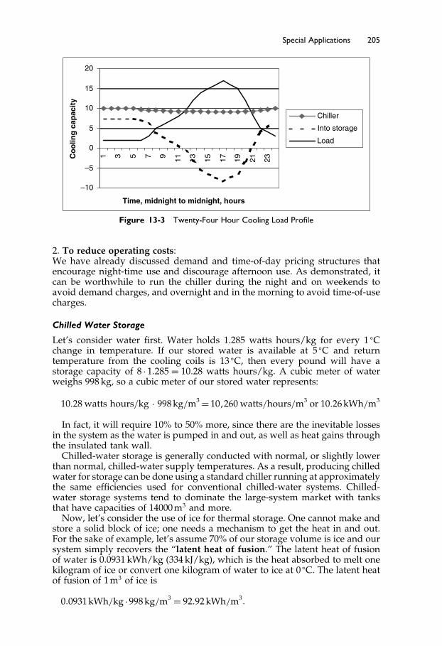
Elsevier UK Ch13-P373998 3-11-2006 8:55a.m. Page:205 Trimsize:6.5×9.5inches
Basal Font:Palatino Margins:Top:40pt Gutter:55pt Font Size:10/11 Text Width:29pc Depth:51 Lines
Special Applications 205
–10
–5
0
5
10
15
20
1 3 5 7 9 11 31 51 7 1 91 12 32
Time, midnight to midnight, hours
yticapac
gnil
oo
C
Chiller
Into storage
Load
Figure 13-3 Twenty-Four Hour Cooling Load Profile
2. To reduce operating costs:We have already discussed demand and time-of-day pricing structures thatencourage night-time use and discourage afternoon use. As demonstrated, itcan be worthwhile to run the chiller during the night and on weekends toavoid demand charges, and overnight and in the morning to avoid time-of-usecharges.
Chilled Water Storage
Let’s consider water first. Water holds 1.285 watts hours/kg for every 1 �Cchange in temperature. If our stored water is available at 5 �C and returntemperature from the cooling coils is 13 �C, then every pound will have astorage capacity of 8 · 1�285 = 10�28 watts hours/kg. A cubic meter of waterweighs 998 kg, so a cubic meter of our stored water represents:
10�28 watts hours/kg · 998 kg/m3 = 10�260 watts/hours/m3 or 10�26 kWh/m3
In fact, it will require 10% to 50% more, since there are the inevitable lossesin the system as the water is pumped in and out, as well as heat gains throughthe insulated tank wall.
Chilled-water storage is generally conducted with normal, or slightly lowerthan normal, chilled-water supply temperatures. As a result, producing chilledwater for storage can be done using a standard chiller running at approximatelythe same efficiencies used for conventional chilled-water systems. Chilled-water storage systems tend to dominate the large-system market with tanksthat have capacities of 14000 m3 and more.
Now, let’s consider the use of ice for thermal storage. One cannot make andstore a solid block of ice; one needs a mechanism to get the heat in and out.For the sake of example, let’s assume 70% of our storage volume is ice and oursystem simply recovers the “latent heat of fusion.” The latent heat of fusionof water is 0.0931 kWh/kg (334 kJ/kg), which is the heat absorbed to melt onekilogram of ice or convert one kilogram of water to ice at 0 �C. The latent heatof fusion of 1 m3 of ice is
0�0931 kWh/kg ·998 kg/m3 = 92�92 kWh/m3�
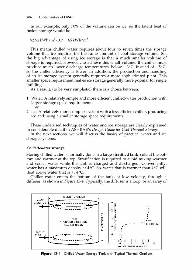
Elsevier UK Ch13-P373998 3-11-2006 8:55a.m. Page:206 Trimsize:6.5×9.5inches
Basal Font:Palatino Margins:Top:40pt Gutter:55pt Font Size:10/11 Text Width:29pc Depth:51 Lines
206 Fundamentals of HVAC
In our example, only 70% of the volume can be ice, so the latent heat offusion storage would be
92�92 kWh/m3 ·0�7 = 65 kWh/m3�
This means chilled water requires about four to seven times the storagevolume that ice requires for the same amount of cool storage volume. So,the big advantage of using ice storage is that a much smaller volume ofstorage is required. However, to achieve this small volume, the chiller mustproduce much lower discharge temperatures, below −3 �C, instead of +5 �C,so the chiller efficiency is lower. In addition, the production and handlingof an ice storage system generally requires a more sophisticated plant. Thissmaller space requirement makes ice storage generally more popular for singlebuildings.
As a result, (to be very simplistic) there is a choice between:
1. Water: A relatively simple and more efficient chilled-water production withlarger storage-space requirements.
or2. Ice: A relatively more complex system with a less efficient chiller, producing
ice and using a smaller storage space requirements.
These underused techniques of water and ice storage are clearly explainedin considerable detail in ASHRAE’s Design Guide for Cool Thermal Storage.
In the next sections, we will discuss the basics of practical water and icestorage systems.
Chilled-water storage
Storing chilled water is normally done in a large stratified tank, cold at the bot-tom and warmer at the top. Stratification is required to avoid mixing warmerand cooler water while the tank is charged and discharged. Conveniently,water has a maximum density at 4 �C. So, water that is warmer than 4 �C willfloat above water that is at 4 �C.
Chiller water enters the bottom of the tank, at low velocity, through adiffuser, as shown in Figure 13-4. Typically, the diffuser is a loop, or an array of
Figure 13-4 Chilled-Water Storage Tank with Typical Thermal Gradient

Elsevier UK Ch13-P373998 3-11-2006 8:55a.m. Page:207 Trimsize:6.5×9.5inches
Basal Font:Palatino Margins:Top:40pt Gutter:55pt Font Size:10/11 Text Width:29pc Depth:51 Lines
Special Applications 207
pipes with slots, to allow the water in or out with minimal directional velocity,to minimize mixing. The chilled water enters at 5 �C (just above 4 �C) and thewarmer water at the top stays stratified above the 5 �C water. As more warmwater is pumped from the top of the tank, through the chiller, and returnedvery gently to the bottom of the tank, the cold layer gradually moves up thetank. When discharging, chilled water is withdrawn at the bottom of the tankand an equal volume of warmed water is returned to the top of the tank. Asimilar diffuser at the top of the tank minimizes turbulent motion and mixingin the water. The process produces a thermal gradient in the tank, such asshown on the right of Figure 13-4.
In Figure 13-5, a simple circuit is shown with the loads and chiller-circuitsbelow the water level of the storage tank. Valves to control the flows betweentank and chiller are not shown in Figure 13-5, since there are several alterna-tives. There are two pipe-loops connected to the storage tank: one belongs tothe chiller and the chiller pump, and the other is the load circuit, consisting ofthe variable volume pump and variable flow loads.
There are up to six possible operating conditions with a storage system, asshown in Figure 13-6.
To maximize savings, the designer must give special consideration to thecontrol of larger storage systems. The seasons when full tank capacity is notrequired are a particular challenge. On one hand, it is wasteful to over store.
STORAGE TANK
VARIABLE VOLUMEDISTRIBUTION PUMP
WARM
COLD
TANK VENT TOATMOSPHERE
CHILLER
CHILLERPUMP
VARIABLE FLOW LOADS
FLOW CONTROL VALVESFOR CHILLER AND TANKARE NOT SHOWN
NOTE:
Figure 13-5 Simple Chilled-Water Storage System

Elsevier UK Ch13-P373998 3-11-2006 8:55a.m. Page:208 Trimsize:6.5×9.5inches
Basal Font:Palatino Margins:Top:40pt Gutter:55pt Font Size:10/11 Text Width:29pc Depth:51 Lines
208 Fundamentals of HVAC
STORAGE Charging Charging Discharging Discharging
CHILLERS Charging Meeting load Meeting load Meeting load Off
LOADS Off On On On On
Figure 13-6 Possible Storage Operating Modes
On the other hand, if you under-store, then you could be faced with muchhigher electricity charges, or a lack of sufficient capacity at peak load periods.Because these penalties are usually much more costly than any savings thatcould be achieved by reducing storage, full storage is generally used.
For maximum storage, the temperature difference between the chilled-watersupply and return water must be as large as possible. In general, chilled-waterstorage is not economical with a temperature differential below 7 �C. A storagetemperature difference of 11 �C should be the target to make the system aseconomical as possible.
Chilled-water storage is not high-tech. Water tanks are a common item inboth steel and concrete and the controls do not have to be very complex.Chiller efficiencies are, often, lower because of the lower chilled-water supplytemperature required. (Remember from Chapter 6, Section 6.3, the efficiency ofa refrigeration circuit falls as the difference in temperature between evaporatorand condenser increases.) However, the chiller efficiency that can be achievedis maximized, since the chiller can always run at full load and the operationis largely at night when ambient temperatures around the cooling towersare lower, allowing a lower condenser-water-supply temperature. Efficiencycan also be improved by using a larger cooling tower, which will drop thecondenser-water-supply temperature.
Exposed tanks should be insulated to minimize heat gain to the cooled storedwater. The size of the storage tank should allow for:
• heat transfer and mixing between warm and cold water levels• ambient heat gain• pumping power.
The net useful cooling output typically varies between 80% and 90% of theinput cooling.
One particularly effective use of chilled-water storage is in the capacityextension of existing facilities.
For example: suppose the client has a building that is running well and needsa substantial addition. You could choose to buy additional chiller capacity forthe additional load. Alternatively, it may be far more economical, on space,installation cost, and operating cost, to add chilled-water storage and havethe existing plant run more continuously through the evening to serve theincreased load.
Ice Storage
There are four main methods of generating ice for ice storage systems: coils,with external melt; coils, with internal melt; ice harvesting; and water innumerous plastic containers.
In External melt systems, ice forms around coils of pipe in a tank. The coilsare cooled, and may be steel or plastic. Just two of the pipes in the coil are
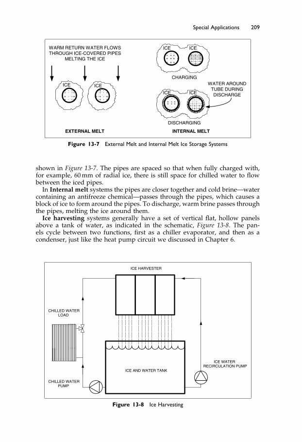
Elsevier UK Ch13-P373998 3-11-2006 8:55a.m. Page:209 Trimsize:6.5×9.5inches
Basal Font:Palatino Margins:Top:40pt Gutter:55pt Font Size:10/11 Text Width:29pc Depth:51 Lines
Special Applications 209
WATER AROUNDTUBE DURINGDISCHARGE
WARM RETURN WATER FLOWSTHROUGH ICE-COVERED PIPES
MELTING THE ICE
ICE ICE
ICEICE
CHARGING
DISCHARGING
ICEICE
EXTERNAL MELT INTERNAL MELT
Figure 13-7 External Melt and Internal Melt Ice Storage Systems
shown in Figure 13-7. The pipes are spaced so that when fully charged with,for example, 60 mm of radial ice, there is still space for chilled water to flowbetween the iced pipes.
In Internal melt systems the pipes are closer together and cold brine—watercontaining an antifreeze chemical—passes through the pipes, which causes ablock of ice to form around the pipes. To discharge, warm brine passes throughthe pipes, melting the ice around them.
Ice harvesting systems generally have a set of vertical flat, hollow panelsabove a tank of water, as indicated in the schematic, Figure 13-8. The pan-els cycle between two functions, first as a chiller evaporator, and then as acondenser, just like the heat pump circuit we discussed in Chapter 6.
ICE WATERRECIRCULATION PUMP
CHILLED WATERPUMP
CHILLED WATERLOAD
ICE HARVESTER
ICE AND WATER TANK
Figure 13-8 Ice Harvesting

Elsevier UK Ch13-P373998 3-11-2006 8:55a.m. Page:210 Trimsize:6.5×9.5inches
Basal Font:Palatino Margins:Top:40pt Gutter:55pt Font Size:10/11 Text Width:29pc Depth:51 Lines
210 Fundamentals of HVAC
The process begins with the panels acting as the chiller evaporator. Wateris continuously pumped over the plates and a layer of ice begins to form onthe plates. After 20–30 minutes the ice reaches an optimum thickness and therefrigerant cycle is reversed. Then the panels act as the condenser, with the hotcondenser gas melting the ice at the plate surface, and the ice falls into the tank.
Ice harvesting systems are attractive since they can be purchased as factorydesigned-and-built systems. If needed, they can have a very high dischargerate, and the full 24-hour charge can be removed in as little as half an hour.
Cooling is removed by passing return chilled water through the ice harvesterand ice-water storage tank to achieve a chilled-water supply temperature of1–2 �C. This is much colder than the 5�5 �C, or warmer, water from standardchilled-water systems, even those using chilled-water storage.
Lastly, water can be contained in plastic spheres. The spheres are eitherpartially filled with water with some air to allow for expansion on freezing,or the spheres have depressions which fill out as the freezing water expands.In these systems, chilled water containing an antifreeze flows through a tankfull of these spheres, to either store or extract cooling.
The major advantages of ice-storage systems are smaller storage tanks andlower chilled-water-supply temperatures. The lower chilled-water-supplytemperatures can be used to increase the system water-temperature differen-tials and to produce very cool, low temperature, supply-air for distributionto the building’s occupied spaces. This results in smaller pipes and smallerair-distribution ducts and supply-air fans. The low-temperature air supplysystem does require carefully designed diffusers that do not dump cold aironto the occupants.
The cooler chilled-water supply temperature from ice storage can be veryuseful in extending an existing chilled-water system. Suppose there are severalbuildings on a main chilled-water loop and the client wants to add anotherbuilding at the end, farthest from the chilled-water plant. The option of increas-ing the chilled-water pipe size may be prohibitively expensive and disruptive.By adding ice-storage, the chilled-water-supply temperature can be reducedfrom 5�5 �C to 2 �C. If the original system was designed for 5�5 �C chilled-watersupply and 13 �C return, the temperature rise was
13 �C−5�5 �C = 6�5 �C�
Now with chilled water at 2 �C the temperature difference is
13 �C−2 �C = 9 �C�
With the same volume flow, the capacity of the piping mains has beenincreased by nearly 40%, which now allows this system’s pipes to serve theremote building without replacing them with larger pipes. Adding insulationto the existing pipes may be necessary.
To achieve the projected savings in energy costs, if the system is not fullyautomated, the operating staff must completely understand and be able toapply the control strategies of the design. With today’s technology, these canbe performed by Direct Digital Controls (DDC), through software. Using DDC,the control sequences can be made fully automatic, and therefore less depen-dent on the operating staff. However, this does require that these systems becommissioned to ensure that the automatic control functions as intended.
Be warned that it is surprising how often operating and maintenance staffdefeat the cleverest software by switching just one piece of equipment to“manual!”
Elsevier UK Ch13-P373998 3-11-2006 8:55a.m. Page:211 Trimsize:6.5×9.5inches
Basal Font:Palatino Margins:Top:40pt Gutter:55pt Font Size:10/11 Text Width:29pc Depth:51 Lines
Special Applications 211
There are several other, less popular, active storage methods that you canresearch elsewhere. Be aware that “less popular” does not mean “unpopular.”Many systems are ideal choices for some specific situations but are not practicalfor every project. Local knowledge and your research can help find the bestchoice for your project.
13.4 The Ground as Heat Source and Sink
The ground can be treated as a large heat source or as a heat sink. In otherwords, one can extract heat from the ground or reject heat to the ground. Thetemperature only a few meters below the surface varies half as much as theambient temperature. Below 3 meters the temperature remains fairly constantin most places.
There are three general methods of using the ground as a heat source orsink: the well, the vertical field, and the horizontal field.
The Well: The oldest method, and in some places the easiest, is to dig a well,then pump the water up and through the heat pump before piping it to drain.Many local codes will not permit this approach and will require you to have asecond well some distance away to discharge the water back into the ground.This all assumes your location has a readily accessible, adequate and reliableflow of “sweet” water. “Sweet” meaning it has no undesirable characteristics,such as dissolved salts that will corrode away both pumps and heat exchangersvery quickly. Local knowledge and test holes can be invaluable.
The horizontal field and vertical field refer to pipe loops in the ground thattransfer heat to or from the ground.
The Vertical Field:
1. The field has been prepared and planned, and then vertical bore holes aredrilled. The vertical depth for the boreholes ranges from 15 to 150 meters,depending on ground conditions and the cost to drill the holes to thesedepths. Boreholes must be spaced well apart to avoid having them thermallyaffecting each other. The effect is minimized with a row of holes, but this is notalways an attractive alternative. A rule of thumb is 6 meters apart, but localconditions, such as underground water flow, can reduce this distance. A testhole can be bored and used to test the heat transfer characteristics of the localsoil conditions to help determine the number of wells and spacing required.
2. Durable U-shaped plastic pipe loops are lowered into the boreholes.3. Each borehole is back-filled with excavated material or with a special mix-
ture to enhance heat transfer with the ground.4. The ends of the pipes are connected to headers, which are routed back to a
building to pumps within the building. The pumps are connected to pipingthat is circuited to one, or more, water coils, each on one side of a heatpump.
Vertical ground-source systems have the following advantages:
• They utilize smaller areas of land than the horizontal system.• Their performance is quite stable (when spaced and sized properly), since
the ground temperature does not vary with the seasons.
Elsevier UK Ch13-P373998 3-11-2006 8:55a.m. Page:212 Trimsize:6.5×9.5inches
Basal Font:Palatino Margins:Top:40pt Gutter:55pt Font Size:10/11 Text Width:29pc Depth:51 Lines
212 Fundamentals of HVAC
• They use the lowest pumping energy and the least amount of pipe.• They often provide the most efficient performance.
Vertical ground source systems have two disadvantages that vary accordingto location:
• They are generally more expensive to install than horizontal systems andcan be prohibitively expensive in hard rock areas.
• The availability of qualified contractors is very limited in some areas.
The Horizontal Field: This method involves burying pipe loops in trenchesor open pits at a depth of at least 1.2 meters. There is a variety of pipe looparrangements that are designed to take advantage of local conditions.
Horizontal systems have the following advantages:
• They are relatively easy to install with readily available, non-specialist equip-ment in areas without rock.
• For rural residential systems, the land requirement is usually not a restriction.• They usually have a lower installed cost than vertical systems and they are
potentially easier to repair.
Disadvantages:
• They require a much larger land area.• They have a more significant variable system performance than the vertical
arrangement, due to greater variations in ground temperature that arise fromseasonal temperatures, rainfall, and shallower burial depth.
• Their efficiency is generally lower than the vertical arrangement, due to fluidtemperature and slightly higher pumping requirements.
Correctly sizing a heat pump for winter heating and summer cooling can bea difficult task. In many climates with cold winters, the winter heating loadcan be much higher than the summer cooling load. Installing a heat pump thatis big enough to do both tasks is often a mistake. If the unit is oversized forsummer cooling, it will cycle excessively and dehumidification will be verypoor to non-existent. The maximum over-sizing above summer load shouldnot exceed 25% for reasonable summer performance. The winter heating loadthat is not supplied by the heat pump is best provided by supplemental heat.
One relatively new opportunity to deal with this issue is the two-speedcompressor unit. Two-speed units may allow for correct sizing for the summerload by cooling at low speed, while high speed may allow the winter heatingload to be more closely met. For heating in these climates, it is very efficient touse a radiant floor system. This is because the temperature difference betweenthe ground and the heat pump heating-supply temperature is lower, thereby,providing a significantly higher efficiency.
An extension of the idea of using “natural” sources for heating or coolingis the idea of using natural ventilation from operable windows. This will becovered in the next section.
13.5 Occupant-Controlled Windows with HVAC
People like to think they have control of their environment. For air-conditionedbuildings without operable windows, there is a desire “to have a thermostat in

Elsevier UK Ch13-P373998 3-11-2006 8:55a.m. Page:213 Trimsize:6.5×9.5inches
Basal Font:Palatino Margins:Top:40pt Gutter:55pt Font Size:10/11 Text Width:29pc Depth:51 Lines
Special Applications 213
my office.” In fact, many maintenance staff have discovered that the presenceof a thermostat can be very satisfying even when it is not connected! Hencethe use of the phrase “dummy thermostat.”
This desire for control is often successfully exercised in the demand foroccupant controlled windows, operable windows. Unfortunately, people arenot good at assessing when to have the window open or when to close it.This is where good communication can have a very beneficial effect. Peopleare generally cooperative if they understand why they should be cooperative.You would be surprised at how many buildings have occupants runningwindow air-conditioners while the windows are open. The owners make noeffort to explain the waste and lack of dehumidification that occurs when theair-conditioner is cooling while the window is open on a hot, humid day. Theresult is fewer satisfied occupants and the owner has a higher electricity, orenergy, bill. If you are faced with a situation like this, try to let the occupantsknow the benefits that will affect them if they use the system more efficiently.
Actual ventilation depends on orientation, building height, wind direction,and wind speed. In narrow buildings with windows on both sides, a crossflow can be very effective. One problem is that on the incoming side occupantsmay experience an unacceptable draft if they are close to the windows.
In winter, in colder climates, the warm, less dense air in buildings tends torise. As a result, there is a constant inflow of air through openings that arelow in the building and a outflow high in the building. An occupant whoopens a ground floor window in a three story apartment building receivesan incoming icy blast. The window is quickly shut and remains closed. Onthe other hand, the person on the third floor can open their window wideand the warm air from the building will flow outward. They can leave theirwindow open, letting the warm air, and energy, of the building continuouslyvent outside. In this situation, the windows are unusable low in the buildingand a great waste of energy for negligible ventilation high in the building.The problem of providing enough ventilation without a huge energy waste isaddressed in Canada and parts of northern Europe by requiring mechanicalventilation in residences. This has, in turn, made a variety of heat recoveryunits quite popular, and in many places mandatory, although their cost isoften not recovered from the energy savings when fan power is included inthe calculations.
In mild climates, operable windows can be used to both ventilate the build-ing and provide overnight pre-cooling with judicious building design anduse.
The ventilation benefits of windows, and the challenges of their operation,are being addressed in some new buildings by having the windows controlledautomatically. The control system may have sensors for wind direction andspeed, solar intensity, as well as interior and exterior temperature sensors toaid in the decision making process.
13.6 Room Air Distribution Systems
Earlier in this course we talked about supplying air to spaces, but we havenot discussed how achieve it. We will do that now. There are four main typesof room air distribution systems: mixing, displacement, underfloor, and taskcontrol. “Mixing” is by far the most popular in North America and “taskcontrol” has yet to gain popularity.

Elsevier UK Ch13-P373998 3-11-2006 8:55a.m. Page:214 Trimsize:6.5×9.5inches
Basal Font:Palatino Margins:Top:40pt Gutter:55pt Font Size:10/11 Text Width:29pc Depth:51 Lines
214 Fundamentals of HVAC
COOLING HEATING
Figure 13-9 Ceiling Diffuser Airflow Pattern for Cooling and Heating
In mixing ventilating systems, the air is supplied, typically at 13–14 �C, ata velocity of over 0.5 m/s (meters per second), through an outlet diffuser orgrill, at the ceiling or high in the sidewall. The objective is to have the supplyair entrain and circulate the room air, to achieve good mixing.
The flow from a typical ceiling diffuser has a velocity profile as shown inFigure 13-9. The air velocity falls as more room air is entrained and the designshould have the velocity no higher than 0.25 m/s in the occupied zone. Whencooling, as shown on the left in Figure 13-9, the cool air is blown out acrossthe ceiling and, although cool and dense, does not immediately drop due tothe “Coanda” effect. The Coanda effect is the property of air to stay againsta surface. For the cool air to drop from the ceiling, room air would have tomove in above it, since otherwise a vacuum would be formed. This takes timeto occur, with the result that the cool supply air travels further across theceiling before dropping than would the same flow if it had been dischargedwell below the ceiling.
The ceiling diffuser works well in the cooling mode. Unfortunately, it doesnot work very well in heating mode, since the warm, less dense, supplyair stays up at the ceiling, out of the occupied zone. The buoyancy effectis particularly problematic with the supply air temperature more than 8 �Chigher than the general room temperature. The flow is shown on the right ofFigure 13-9. The air enters the room and stays at the ceiling level except wherethe cool window creates a downdraft that provides a cool to cold draft overthe occupants’ feet.
Mixing works well for cooling and can produce an even temperaturethroughout the space. Disadvantages include:
• The air velocity has to be low enough throughout the occupied area to avoiddrafts, so there is a tendency for inadequate air movement in some areas.
• Any pollutants in the space can be spread throughout the space.• All loads must be absorbed within the mixed air.
Displacement ventilation is the opposite of mixing. Displacement ventilationaims to avoid mixing in the occupied zone. Air, a little cooler than the space,is introduced at a low velocity �<0�5 m/s� through large area diffusers in thewall close to the floor. The air flows slowly and steadily across the space untilit passes a warm object—a person or a piece of equipment. The warmth causessome of the air to rise up out of the occupied zone carrying pollutants andheat with it. Above the occupied zone, mixing occurs and the return outlet at

Elsevier UK Ch13-P373998 3-11-2006 8:55a.m. Page:215 Trimsize:6.5×9.5inches
Basal Font:Palatino Margins:Top:40pt Gutter:55pt Font Size:10/11 Text Width:29pc Depth:51 Lines
Special Applications 215
Figure 13-10 Schematic of Displacement Ventilation
the ceiling level draws the some of the mixed air out of the space. The flowpattern is shown in Figure 13-10.
The air supplied cannot be more than about 4 �C less than the occupiedspace temperature, in order to avoid excessive cooling on the people closestto the outlets. This restriction severely limits the effective cooling capacity ofthe system. For cooler climates, such as Scandinavia, where the system is verypopular, this load restriction is not as significant. Where higher internal loadsmust be absorbed, there are methods of entraining room air into the supplyair to increase the effective flow into the room while still staying within 4 �Cless than room temperature.
The air movement in the space separates into the lower displacement zonewith a recirculation zone above. In a well-designed space, the recirculationzone is just above the occupied zone.
The objective of the system is to have the occupants and the equipmentin a flow of clean air, with their own heat causing convection around them.This will lift their pollutants up, out of the occupied zone. In addition, theconvection heat from surfaces and lights above the occupied zone do not affectthe temperature in the occupied zone. As a result the air leaving the room canbe warmer than would be acceptable in the occupied zone.
Underfloor Air Distribution (UFAD) is supplied from a raised floor throughnumerous small floor grilles. The floor typically consists of 600 mm squaremetal plates, or tiles, supported by a 250–450 mm high supporting leg, orcolumn, at each corner. Some of the tiles have outlet grilles installed in them.The tiles can be lifted and moved around, making grille re-location, addition,or removal, a simple task as shown in Figure 13-11.
Air, at 14�5–18 �C, is supplied to the cavity and discharges through the floorgrilles. The floor grilles are designed to create mixing, so that the velocityis below 0.25 m/s within 1.2 meters of the floor. You can think of the air asturbulent columns spreading out above the 1.2 meter level to form a verticaldisplacement flow toward the ceiling. Return air is taken from the ceilingor high on the wall. The rising column of air takes contaminants with it upand out of the breathing zone. This sweep-away action is considered moreeffective rather than mix-and-dilute. As a result, the ventilation requirementsof ASHRAE Standard 62.1 can be satisfied with 10% less outside air.
There are numerous outlets, since the individual outlet volume is typicallylimited to 50 L/s. The entering air does not sweep past the occupants, as occurs

Elsevier UK Ch13-P373998 3-11-2006 8:55a.m. Page:216 Trimsize:6.5×9.5inches
Basal Font:Palatino Margins:Top:40pt Gutter:55pt Font Size:10/11 Text Width:29pc Depth:51 Lines
216 Fundamentals of HVAC
FAN COIL
Figure 13-11 Underfloor Air Distribution (UFAD)
in displacement ventilation, so there is no restriction on cooling capacity. Thereis, however, a limit on how well the system will work with rapidly changingloads. For spaces with high solar loads, thermostatically controlled fans orother methods are required to modulate the capacity to match the changingload.
Since the air is rising toward the ceiling, the convection heat loads above theoccupied zone do not influence the occupied zone temperature. Therefore, thereturn air temperature can be warmer than the occupied zone and a return airtemperature sensor is a poor indicator of occupied zone temperature.
The cool air flows continuously over the structural floor that somewhat actsas a passive thermal storage unit. This storage can be used to reduce peakloads.
For perimeter heating, small fan-coil units can be installed under the floor,using finned hot water pipes or electric coils. In a similar way, conferencerooms that have a highly variable load can have a thermostatically controlledfan to boost the flow into the room when it is in use.
A modification of the underfloor system with individual grilles is the use ofa porous floor. The floor tiles are perforated with an array of small holes, anda porous carpet tile allows air to flow upwards over the entire tile area. Thisis a modification of the standard grill and has yet to gain popularity.
The underfloor air delivery system has the following advantages:
• Changing the layouts of partitions, electrical, and communications cablesis easy. For buildings with high “churn” (frequent layout changes) thisflexibility may, in itself, make the added cost of the floor economicallyjustified.
• The flow of air across the concrete structural floor provides passive thermalstorage.
• When the main supply duct and branches to the floor plenums are part ofa well-integrated architectural design, the air supply pressure drop can bevery low, resulting in fan-horsepower savings.
• Less ventilation outside air can potentially be used.

Elsevier UK Ch13-P373998 3-11-2006 8:55a.m. Page:217 Trimsize:6.5×9.5inches
Basal Font:Palatino Margins:Top:40pt Gutter:55pt Font Size:10/11 Text Width:29pc Depth:51 Lines
Special Applications 217
Figure 13-12 Task/Ambient Conditioning Supplied from Underfloor Distribution
Disadvantages include:
• A significant cost per square meter for the floor system supply, installation,and maintenance.
• A tendency to require a greater floor-to-floor height, since space for lightsand return air ducts is still required at the ceiling level.
Our fourth and final type of air distribution system is most often a variationof the underfloor system. It is the Task\Ambient Conditioning system, TAC.With TAC each occupant workstation is supplied with cooling air and a degreeof control over this airflow, airflow direction, and temperature, as shown inFigure 13-12. In a typical arrangement, one or two supply air nozzles are mountedabove the work surface. The occupant can easily alter the velocity and directionof flow. Temperature may be controlled by mixing room air into the supply air,or by a resistance or radiant electric heater controlled by the occupant.
The ability to control their own environment is very popular with many occu-pants, though the measured conditions are not greatly different from occupantsin the same building without a TAC. One specific advantage of the TAC forthe occupant is the ability to modify the air speed. Since this system is in additionto the underfloor supply, there is significant research work being done to provethat the cost is more than recovered in improved staff productivity.
This completes our look at supplying air to occupied spaces. As with somany issues in HVAC, the climate and the local norms and experience willoften drive decisions as much as technical merit.
Having discussed room air distribution we are now going to move to theother end of the system, where the ventilation air is brought into the buildingthrough the air handler.
13.7 Decoupled and Dedicated Outdoor Air Systems
Our last area of discussion relates to outdoor air. There are situations wheremixing the outdoor air with return air and conditioning the mixture is not agood choice.
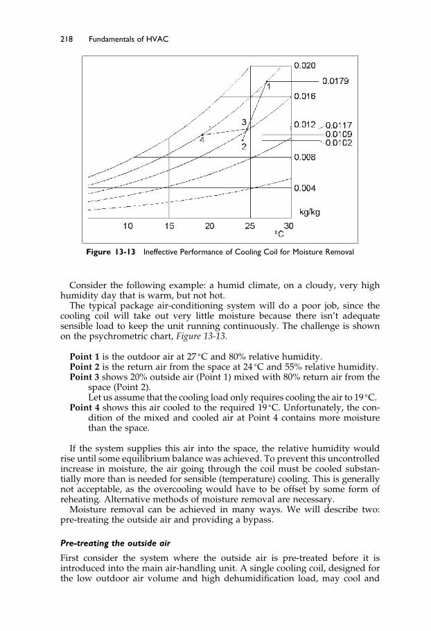
Elsevier UK Ch13-P373998 3-11-2006 8:55a.m. Page:218 Trimsize:6.5×9.5inches
Basal Font:Palatino Margins:Top:40pt Gutter:55pt Font Size:10/11 Text Width:29pc Depth:51 Lines
218 Fundamentals of HVAC
Figure 13-13 Ineffective Performance of Cooling Coil for Moisture Removal
Consider the following example: a humid climate, on a cloudy, very highhumidity day that is warm, but not hot.
The typical package air-conditioning system will do a poor job, since thecooling coil will take out very little moisture because there isn’t adequatesensible load to keep the unit running continuously. The challenge is shownon the psychrometric chart, Figure 13-13.
Point 1 is the outdoor air at 27 �C and 80% relative humidity.Point 2 is the return air from the space at 24 �C and 55% relative humidity.Point 3 shows 20% outside air (Point 1) mixed with 80% return air from the
space (Point 2).Let us assume that the cooling load only requires cooling the air to 19 �C.
Point 4 shows this air cooled to the required 19 �C. Unfortunately, the con-dition of the mixed and cooled air at Point 4 contains more moisturethan the space.
If the system supplies this air into the space, the relative humidity wouldrise until some equilibrium balance was achieved. To prevent this uncontrolledincrease in moisture, the air going through the coil must be cooled substan-tially more than is needed for sensible (temperature) cooling. This is generallynot acceptable, as the overcooling would have to be offset by some form ofreheating. Alternative methods of moisture removal are necessary.
Moisture removal can be achieved in many ways. We will describe two:pre-treating the outside air and providing a bypass.
Pre-treating the outside air
First consider the system where the outside air is pre-treated before it isintroduced into the main air-handling unit. A single cooling coil, designed forthe low outdoor air volume and high dehumidification load, may cool and
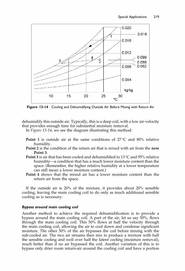
Elsevier UK Ch13-P373998 3-11-2006 8:55a.m. Page:219 Trimsize:6.5×9.5inches
Basal Font:Palatino Margins:Top:40pt Gutter:55pt Font Size:10/11 Text Width:29pc Depth:51 Lines
Special Applications 219
Figure 13-14 Cooling and Dehumidifying Outside Air Before Mixing with Return Air
dehumidify this outside air. Typically, this is a deep coil, with a low air-velocitythat provides enough time for substantial moisture removal.
In Figure 13-14, we see the diagram illustrating this method:
Point 1 is outside air at the same conditions of 27 �C and 80% relativehumidity.
Point 2 is the condition of the return air that is mixed with air from the newPoint 3.
Point 3 is air that has been cooled and dehumidified to 13 �C and 95% relativehumidity—a condition that has a much lower moisture content than thespace. (Remember, the higher relative humidity at a lower temperaturecan still mean a lower moisture content.)
Point 4 shows that the mixed air has a lower moisture content than thereturn air from the space.
If the outside air is 20% of the mixture, it provides about 20% sensiblecooling, leaving the main cooling coil to do only as much additional sensiblecooling as is necessary.
Bypass around main cooling coil
Another method to achieve the required dehumidification is to provide abypass around the main cooling coil. A part of the air, let us say 50%, flowsthrough the main cooling coil. This 50% flows at half the velocity throughthe main cooling coil, allowing the air to cool down and condense significantmoisture. The other 50% of the air bypasses the coil before mixing with thesub-cooled air. The two air streams then mix to produce a mixture with halfthe sensible cooling and well over half the latent cooling (moisture removal),much better than if no air bypassed the coil. Another variation of this is tobypass only drier room return-air around the cooling coil and have a portion

Elsevier UK Ch13-P373998 3-11-2006 8:55a.m. Page:220 Trimsize:6.5×9.5inches
Basal Font:Palatino Margins:Top:40pt Gutter:55pt Font Size:10/11 Text Width:29pc Depth:51 Lines
220 Fundamentals of HVAC
of the return air mix with the outside air, which is then sub-cooled as it passesthrough the coil.
We have briefly considered using alternative arrangements to deal withhigh moisture removal. Now we will consider a situation where differentrequirements make a dual-path system attractive.
Consider a building that includes a large kitchen and an eating area. Thebuilding could be designed to have all the necessary kitchen makeup air comein through the main air handler. However, because the kitchen is a moreindustrial environment, rather than an office environment, the kitchen makeupair does not need to be conditioned to the same moisture and temperatureconditions as the main air supply to the building. In addition, the kitchenmay start operation before the rest of the building and shut down well beforethe rest of the building. This is a case of a mismatch in requirements and amismatch in timing.
Therefore, it is often better to provide the kitchen makeup air from twosources. First, there is the air from the eating area. In order to avoid distributingfood smells around the building, this air from the eating area should not bereturned to the main air handler. Instead, it should form the first part of thekitchen exhaust hood makeup air. The transfer can be by a plain opening, anopen door, or a duct with a fire damper, depending on local codes and designrequirements. The rest of the kitchen exhaust makeup air can be providedfrom a separate air handler designed to condition the incoming air to providesuitable kitchen working conditions, often a much less onerous requirement.
Summary
13.2 Radiant Heating and Cooling Systems
Radiant heaters are defined as units that have more than 50% of their heatingoutput achieved through radiation.
Radiant Heating: High temperature, or infrared, units operate at over 150 �C.There are three main types of high temperature units:
• High intensity units are electric lamps operating from 1000–2750 �C.• Medium intensity units operate in the 650–1000 �C range and are either metal-
sheathed electric units or a ceramic matrix heated by a gas burner.• Low intensity units are gas-fired and use the flue as the radiating element
Important safety and control issues to consider include both heater locationand thermostat location.
Radiant Cooling: This is always achieved by using a “large area” panelsystem. Issues for consideration include: space moisture level, location of insu-lation on the panels, and the response time of the system.
13.3 Thermal Storage Systems
Thermal storage can be “active” or “passive.”Passive thermal storage uses some part of the building mass or contents
like a thermal flywheel to store heat or cooling and to release it over time toreduce the heating or cooling load.

Elsevier UK Ch13-P373998 3-11-2006 8:55a.m. Page:221 Trimsize:6.5×9.5inches
Basal Font:Palatino Margins:Top:40pt Gutter:55pt Font Size:10/11 Text Width:29pc Depth:51 Lines
Special Applications 221
Active thermal storage takes place when a material is specifically cooled orheated, with the object of using the cooling or heating effect at a later time.
13.4 Chilled Water and Ice Storage
There are two reasons to use chilled water and ice storage: to potentially reduceinstallation costs and to reduce operating costs.
Chilled-water Storage: Storing chilled water is normally done in a largestratified tank, cold at the bottom and warmer at the top. One economical useof chilled-water storage is in the capacity extension of existing facilities.
Ice Storage: There are four main methods of generating ice for ice storagesystems: coils with external melt; coils with internal melt; ice harvesting; andwater in numerous plastic containers. Ice storage can result in smaller pipes,ductwork, and fans, when low-temperature supply-air is used. Ice storagerequires less space than water for the same storage capacity.
13.5 The Ground as Heat Source and Sink
The ground can be treated as a large heat source or as a heat sink: one canextract heat from the ground or reject heat to the ground. There are threegeneral methods of using the ground as a source or sink, the well, the horizontalfield, and the vertical field.
13.6 Occupant-Controlled Windows with HVAC
Many people like to have control of their environment, resulting in a demandfor occupant controlled windows, operable windows. Unfortunately, peopleoften are not good at assessing when to have the window open or when toclose it.
Actual ventilation depends on orientation, building height, wind direction,and wind speed. In mild climates, with judicious building design and use,operable windows can be used to both ventilate the building and provideovernight pre-cooling.
13.7 Room Air Distribution Systems
There are four main types of room-air distribution: mixing, displacement,underfloor, and task control. Mixing is by far the most popular in NorthAmerica and task control has yet to gain popularity.
13.8 Decoupled and Dedicated Outdoor Air Systems
There are situations where mixing the outdoor air with return air and con-ditioning the mixture is not a good choice. Examples include warm, humidclimates; or where fumes should not be recirculated with the building air.

Elsevier UK Ch13-P373998 3-11-2006 8:55a.m. Page:222 Trimsize:6.5×9.5inches
Basal Font:Palatino Margins:Top:40pt Gutter:55pt Font Size:10/11 Text Width:29pc Depth:51 Lines
222 Fundamentals of HVAC
Your Next Step
The objective of this course has been to provide an understanding of HVACin general, and to introduce the more common systems used in the HVACindustry. We have not gone into great detail on any subject but hope to haveprovided enough knowledge to understand how systems work and for thereader to decide what he or she wants to learn more about.
Fundamentals Series
For further study, the ASHRAE Learning Institute has the following titles inthis Fundamentals Series.
• Fundamentals of Thermodynamics• Fundamentals of Thermodynamics and Psychrometrics• Fundamentals of HVAC Systems (this book)• Fundamentals of Heating and Cooling Loads• Fundamentals of Air System Design• Fundamentals of Water System Design• Fundamentals of Heating Systems• Fundamentals of Electrical Systems and Building Electrical Energy Use• Fundamentals of HVAC Control Systems• Fundamentals of Refrigeration
ASHRAE Handbooks
The four ASHRAE Handbooks are an excellent source of information on allaspects of heating, ventilating, air conditioning, and refrigeration. Each year,one volume is updated and published, following a four-year cycle. Membersreceive a copy of the current year’s edition each year and copies can be indi-vidually purchased. All four handbooks can also be obtained on a CD.
Fundamentals – This volume contains information on the properties andbehavior of air, water, and other fluids, and how they flow in ducts andpipes. It includes the theory and practice of calculating heat gains andheat losses through all types of building materials.
Systems and Equipment – This volume includes HVAC systems, air han-dling and heating equipment, package equipment, and general compo-nents such as pumps, cooling towers, duct construction, and fans.
Applications – This volume begins with a section on how to apply systemsand equipment to comfort, industrial, and transportation situations.Following this, there is a section on general issues, such as operation andmaintenance, and energy management. The Handbook finishes withgeneral applications such as the design of intakes and exhausts, seismicrestraint, water treatment, and evaporative cooling.
Refrigeration – This volume provides very detailed information on allaspects of refrigeration equipment and practices, followed by sectionson food storage, food freezing, low temperature refrigeration, andindustrial applications that include ice rinks.

Elsevier UK Ch13-P373998 3-11-2006 8:55a.m. Page:223 Trimsize:6.5×9.5inches
Basal Font:Palatino Margins:Top:40pt Gutter:55pt Font Size:10/11 Text Width:29pc Depth:51 Lines
Special Applications 223
As a matter of policy, the ASHRAE Handbooks are not commercial, and donot recommend any product.
Manufacturers
Manufacturers put significant effort into training their staff about their prod-ucts. Do not be shy to ask them about their products. When choosing a product,ask the representative: “What would you suggest?” “Is it suitable?” “Is theresomething better?” “Is there something less expensive?” “Is there somethingmore efficient?” “Who has one of these in and working and can I call them?”Be sure to ask more than one manufacturer’s representative for information, soyou can get a different perspective on what is available for your application.Don’t hesitate to ask manufacturers for sales materials and read them with analert mind. Is there something here that could really work well in this situa-tion? Is this too good to be true? If so, why? Be realistic—manufacturers putthe best light on their product. The challenge for you is to find the productthat will perform well in your situation.
Keep asking, keep learning, and have fun doing it.
Bibliography
ASHRAE. 2005. 2005 ASHRAE Handbook—Fundamentals. Atlanta: American Society ofHeating, Refrigerating and Air-Conditioning Engineers, Inc.
ASHRAE. 2004. 2004 ASHRAE Handbook—HVAC Systems and Equipment. Atlanta: Amer-ican Society of Heating, Refrigerating and Air-Conditioning Engineers, Inc.
ASHRAE. 2003. 2003 ASHRAE Handbook—HVAC Applications. Atlanta: American Soci-ety of Heating, Refrigerating and Air-Conditioning Engineers, Inc.
ASHRAE. 2002. 2002 ASHRAE Handbook—Refrigeration. Atlanta: American Society ofHeating, Refrigerating and Air-Conditioning Engineers, Inc.
ASHRAE. 1993. Design Guide for Cool Thermal Storage. Atlanta: American Society ofHeating, Refrigerating and Air-Conditioning Engineers, Inc.
Bauman, Fred S. 2003. Underfloor Air Distribution Design Guide. Atlanta: American Soci-ety of Heating, Refrigerating and Air-Conditioning Engineers, Inc.
Harriman, Lew. 2001. Humidity Control Design Guide. Atlanta: American Society ofHeating, Refrigerating and Air-Conditioning Engineers, Inc.
Epilogue
This story is not a part of the text of the book. I have heard and read a numberof variations of it over the years. To me, it speaks of the importance of whatwe are doing, and what we can be doing, as members of this profession:
Long ago a king decided to go out on his own to see his kingdom. He borrowed somemerchant’s clothes and dressed so that no one would recognize him.
He came to a large building site and went in while the gatekeeper was dealingwith a delivery of huge wooden beams. As he walked around the site he came upon astonemason, who was chiseling at a large piece of stone.
“What are you doing?” the king asked.“Oh, I’m making this stone to fit that corner over there.” said the man, pointing.“Very good.” Said the king, and walked on. The king approached another stonemason
and asked, “What are you doing?”

Elsevier UK Ch13-P373998 3-11-2006 8:55a.m. Page:224 Trimsize:6.5×9.5inches
Basal Font:Palatino Margins:Top:40pt Gutter:55pt Font Size:10/11 Text Width:29pc Depth:51 Lines
224 Fundamentals of HVAC
“I’m doing my job. I’m a stonemason. It’s great working here, lots of overtime,enough to pay for an extension to the cottage,” said the man with a big grin.
“Very good,” said the king, and walked on.The king stood and watched the third stonemason, who was carefully working on a
detail, before asking him, “What are you doing?”The man paused, and looked up, considering his reply. Then he answered, “I am
building a cathedral.”

Elsevier UK Index-P373998 3-11-2006 1:51p.m. Page:225 Trimsize:6.5×9.5inches
Basal Font:Palatino Margins:Top:40pt Gutter:55pt Font Size:10/11 Text Width:29pc Depth:51 Lines
Index
acoustical environment 7active thermal storage 202–4, 221activity level, and comfort 8, 35–6actuator 75, 168adiabatic process 18, 32air-and-water systems 26–7air-conditioning systems
basic system 20–4choice of system 27–30, 32, 82, 87components 20–2, 32, 87controls 27definition 4economizer cycle 22–4, 32, 93processes 3–4, 9rooftop units 85–8, 90single-zone systems 72–3split systems 88–9system performance requirements
83–5, 90window air-conditioners 4, 27,
79–80, 112zoned systems 24–7, 32
air distribution systems 213–17, 221air handlers see single zone air handlersair inlet 74–5air quality, and comfort 6–8, 47–9, 60air-side economizers 190–1, 196air speed, and comfort 38, 41air temperature
and comfort 37mixed-temperature sensor 75variations 42
all-air systems 24–5advantages 93–4bypass box systems 98–9disadvantages 94dual-duct systems 99–100, 101
dual-duct variable air volumesystems 104–5
dual path outside air systems 105multizone systems, 102–3reheat systems 25, 94–6, 106three-deck multizone systems 103variable air volume (VAV) system
26, 104–5all-water systems 27analog electronic controls 156analog input and output 165art work preservation, HVAC
systems 6ASHRAE (American Society of Heating,
Refrigerating and Air-ConditioningEngineers)
ASHRAE/IESNA Standard 90.1–2004Energy Standard for Buildings ExceptLow-Rise Residential Buildings 3,168, 175, 179, 183–6
Guideline 13–2000 Specifying DirectDigital Control Systems 175
psychrometric chart 12–20Standard 135–2004 A Data
Communication Protocol for BuildingAutomation and ControlNetworks 173
Standard 52.1–1992 Gravimetric andDust Spot Procedures for Testing AirCleaning Devices 50
Standard 52.2–1999 Method for TestingGeneral Ventilation Air CleaningDevices for the Removal Efficiency byParticle Size 51
Standard 55–2004 ThermalEnvironmental Conditions for HumanOccupancy 35

Elsevier UK Index-P373998 3-11-2006 1:51p.m. Page:226 Trimsize:6.5×9.5inches
Basal Font:Palatino Margins:Top:40pt Gutter:55pt Font Size:10/11 Text Width:29pc Depth:51 Lines
226 Index
ASHRAE (Continued)Standard 62 Ventilation for Acceptable
Indoor Air Quality 54–9Standard 62.1–2004 Ventilation for
Acceptable Indoor Air Quality46, 54–9
Standard 62.2–2004 Ventilationand Acceptable Indoor Air Qualityin Low Rise Residential Buildings46, 54
axial fan 78
BACnet 173bag filter 52, 53barometric dampers 194boilers
central plant 140–2, 145condensing boiler, 187replacement 144, 183steam boilers 125, 145, 152two boiler system 144–5
boreholes 211breathing zone 55building design
and air-conditioning 28and energy conservation 179–83
bypass box systems 98–9bypass damper 98
carbon dioxide 57–9carbon monoxide 47carcinogens 48ceiling plenum 99ceilings, radiant heating and
cooling 198central plants 139–52
boilers 140–2, 145chillers 145–8comparison with local
plants 140–2cooling towers 148–51
centrifugal compressor 146centrifugal fan 78changeover system, fan coils 116chilled water system 133–4, 171chilled water, storage 205–8chillers
central plant 139–42, 145–8energy efficiency 142
client issues 29
climateand dual-path systems 105and economizer cycle 22–4, 32effects of 4and single zone air-handlers 87, 81and thermal storage 201–11and zones 62–9
closed loop controls 158–60, 161closed water circuit 135, 136clothing, and comfort 8, 36Coanda effect 214Coefficient of Performance
(COP), 185comfort
and environment 6–8and indoor air quality 45, 47–9see also thermal comfort
comfort cooling see air-conditioningsystems
comfort envelope 39, 40compressor, in refrigeration
equipment 78computers see Direct Digital
Controls (DDC)condensate, steam systems 123–5condenser, in refrigeration equipment 78condenser water 134–6, 140, 146condensing boiler 130, 187contaminants
filtration 50–3health effects 47, 48, 54indoor air quality 46, 47source control 49–50
control logic 76, 163controlled device 160controlled variable 159controller 160controls
basics 156–61choice of 155closed loop 158–60Direct Digital Controls (DDC), 156,
163–8, 172–5economizers 190electric 155electronic 156languages 172open loop 160–1pneumatic 156self-powered 155thermal storage 198time control 161

Elsevier UK Index-P373998 3-11-2006 1:51p.m. Page:227 Trimsize:6.5×9.5inches
Basal Font:Palatino Margins:Top:40pt Gutter:55pt Font Size:10/11 Text Width:29pc Depth:51 Lines
Index 227
convection heating 110–13cooling
evaporative cooling 192–4radiant cooling 113, 198–201
cooling coil 18, 22, 77cooling towers 78, 135–6, 140, 148–51costs 29, 186, 204
dampersin air-conditioning system 20, 74–5bypass damper 98
data gathering panel (DGP), 174dead band 113, 163decoupled outdoor air systems 217–20dehumidification 105desiccant wheels 189–90dew point temperature 13digital/binary input and output 164dilution ventilation 54Direct Digital Controls (DDC) 156,
168–75, 210inputs and outputs 163naming conventions 165sequence of operations 165–8, 171single zone air handlers 168–72system architecture 173–5
direct evaporative cooling 192–4disease, and air quality 47–8displacement ventilation 214drafts 41drift eliminators 149dual-duct systems 99–102dual-duct variable air volume
systems 104–5dual-path outside air systems 105, 220dust spot efficiency 51
economizersair-side economizers 190–2economizer cycle 22–4, 32, 93water-side 190–2
electric controls 155, 156electricity, costs, 77, 204electric thermal storage (ETS) heater 202electronic controls 156electronic filter 52energy conservation
air-side economizers 190–1ASHRAE/IESNA Standard
90.13, 183–6
building design 179–83building pressure control 194evaporative cooling 192–4heat recovery 195water-side economizers 190–2
energy-cost budget method 186Energy Efficiency Ratio (EER), 185energy efficiency, hot water
systems 130–33Enthalpy 15–16, 32, 76entrained air 117environment, for human comfort
6–8, 9evaporative cooling 192–4evaporator 79expansion valve 79expectations, and comfort 8, 37, 38
fan coils 114–17fan, in air-conditioning system
75, 78, 89farm animals, HVAC systems 11filters 20, 52–3, 76firing rate 144float and thermostatic steam trap 123floors
radiant floor 113, 114, 120, 130,187, 198
surface temperature 42four-pipe system, fan coil 116frozen food storage, HVAC systems 5
gain 158greenhouse gas emissions 3ground, heat source and sink 198, 211
headpressure 192water flow 81, 135
health, and air contaminants 48heating
hydronic systems 110–13psychrometric chart 12–20radiant heating 198–201steam systems 122, 123–5, 137water systems 122, 133, 137
heating coilin air-conditioning system 20, 76–7fan coils 114–17, 121
heat pipes 188

Elsevier UK Index-P373998 3-11-2006 1:51p.m. Page:228 Trimsize:6.5×9.5inches
Basal Font:Palatino Margins:Top:40pt Gutter:55pt Font Size:10/11 Text Width:29pc Depth:51 Lines
228 Index
heat pumpsair-to-air system 82closed loop systems 120ground source heat pumps 90, 118, 130water source heat pumps 118, 121
heat recovery 119, 142, 186, 195desiccant wheels 189heat pipes 178, 188run-around energy recovery coils 187
HEPA filter 52hospitals
ceiling panel heating 114, 201dual-duct systems 100filters 50, 76HVAC systems 3
hotelsexpectations 8, 37four-pipe fan-coil system 116ventilation 55
hot-water fan coils 116hot water systems 129, 130, 137
boilers 142–5, 152energy efficiency 130, 179
human comfort see comforthumidification, psychrometric
chart 17–18humidifier, in air-conditioning
system 22, 77humidistat 22, 69humidity
and comfort 5, 38, 43dehumidification 4, 18–20, 105relative humidity 13–15and zones 62, 64
humidity ratio (W) 12, 38HVAC (Heating, Ventilating and Air
Conditioning)history of 2–3, 8–9system objectives 4–6, 9
hydronic circuits 123hydronic systems 108–21
advantages 109architecture of 122–38control of 109, 111–13disadvantages 109fan coils 114–17natural convection and low
temperature radiation systems109–13, 120
panel heating and cooling113–14, 120
steam piping systems 125, 137
two pipe induction systems 117, 121and ventilation 106, 109, 113water piping systems 120, 140water source heat pumps 118, 121
ice, storage 204, 208IESNA (Illuminating Engineering Society
of North America) see ASHRAE(American Society of Heating,Refrigerating and Air-ConditioningEngineers), ASHRAE/IESNAStandard 90.1–2004
indirect evaporative cooling 192, 193individuals, and comfort 6, 8, 48indoor air quality (IAQ) 3, 45–60
contaminants 46dilution 49, 53filtration 50–2source control 49–50ventilation 45–60
Induction Reheat Unit 95induction, two pipe induction
systems 117, 121infiltration 14, 78, 117Integrated Part-Load Value (IPLV) 185Internet 27, 141, 173interoperability 173
languages, controls 172–3latent heat 15, 17, 32, 84latent heat of fusion 205Leadership in Energy and Environmental
Design (LEED) 186, 195legionella 48, 151lighting
and comfort 7energy conservation 181, 185and HVAC 7
low-grade heat 186Low-Temperature Reheat Unit with
Induced Air 95, 96
mechanically conditioned spaces, comfortconditions 40
MERV (Minimum Efficiency ReportingValues) 51–2, 116
mixed temperature sensor, inair-conditioning system 75
mixing chamber, in air-conditioningsystem 20
Elsevier UK Index-P373998 3-11-2006 1:51p.m. Page:229 Trimsize:6.5×9.5inches
Basal Font:Palatino Margins:Top:40pt Gutter:55pt Font Size:10/11 Text Width:29pc Depth:51 Lines
Index 229
modulating controls 156, 157mold, control of 47, 194multiple zone air systems 92–107multizone systems 102, 103
offset 158, 176on-off controls 157on-off input and output 164open loop control system 160open water circuit 136outdoor air, dual-path
system 105, 107outdoor reset 112, 130, 160, 161outside air damper, in air-conditioning
system 20, 59overshoot 158, 176
panel filter 52panel heating and cooling 108, 113,
120, 198passive thermal storage
202, 220personal environment model 7physical space, and comfort 9piping, water systems 128–9pleated filter 53pneumatic controls 156pollutants see contaminantsponding, steam systems 125pressure
building pressure 194, 196and zones 67
proportional control 157, 158protocols 173psychosocial situation 8psychrometric chart 12–20, 31
acceptable temperature andhumidity 41
cooling coil 19, 22cooling towers 148, 153design of 12evaporative cooling 192heating 16humidification 17relative humidity 13–15
pump curve 128pumps
hot water systems 129–33, 137water systems 137
radiant cooling 201, 220radiant floor 113–14, 130, 198radiant heating
high temperature 198, 220low temperature, 109, 120
radiant temperature 37, 42radiators, heating system
110, 120radon 47reciprocating compressor 146recuperator 142refrigerant-based systems 27refrigeration
equipment 78–83, 89history of 2see also chillers
reheat system 25, 94, 106Induction Reheat Unit 95Low-Temperature Reheat Unit with
Induced Air 95, 96relative humidity 13–15relief air 74reset
chilled water 182heating 182outdoor reset 112, 130, 160–1
reset controller 161return fan 78rooftop units 85, 90room air distribution systems
213–17, 221run-around energy recovery coils 187
safety issues, steam systems 122,123, 137
saturation line 13, 32saturation point 13seasonal efficiency 141, 152secondary air see entrained airself-powered controls 155sensible heat 15, 84sensor 160setpoint 160setpoint temperature 69, 160sick building syndrome 49single zone air handlers 71–90
components 73–8direct digital control (DDC) 168–72
solar gain 66solar heating, water 202

Elsevier UK Index-P373998 3-11-2006 1:51p.m. Page:230 Trimsize:6.5×9.5inches
Basal Font:Palatino Margins:Top:40pt Gutter:55pt Font Size:10/11 Text Width:29pc Depth:51 Lines
230 Index
spacesattributes for comfort 6and zones 63
speed of reaction 176split systems 88, 90standalone panel 166, 174static lift 135steam systems 122, 123–5, 137
boilers 142, 152safety issues 125, 140
steam traps 125, 140storage heater 202stratified tank 221system choice matrix 30, 32system curve 128system head 128
Task/Ambient Conditioning system(TAC) 217
temperature see air temperature; radianttemperature
thermal comfortconditions for 6, 38, 43definition 34factors 35, 43non-ideal conditions 41non-standard groups 42
thermal storage 198, 201–11, 220active 202chilled water storage 205–11controls 208ice storage 208–11passive 202
thermal variation, zones 66thermostatic steam trap 123thermostats 69, 114, 161three-deck multizone systems 103time control 161timing, and zones 116tobacco smoke 48, 53transducer 156, 165turn-down ratio 144, 152Turn it off, Turn it down, Turn it in 183two pipe induction systems 117, 121
Under Floor Air Distribution (UFAD) 215unitary refrigerant-based systems 27
variable air volume (VAV) systems 26,96–8, 104
controls 155direct digital control (DDC) 163–8dual-duct system 106, 107
variable input and output 165ventilation
acceptable indoor air quality 60air distribution 213–17, 221and hydronic heating
systems 113, 120occupant-operated windows 41, 113,
212, 221zones 66
vertical temperature difference 42
water heating, passive 202water piping systems 120, 140
chilled water systems 122,133, 210
condenser water 134–6hot water systems 130, 137
water-side economizers 191, 196water source heat pumps 118, 121water systems see hydronic systemswater vapor, humidity ratio 12web server 175wells 118, 211window air-conditioners 4, 27,
112, 213windows
and energy conservation 179, 183occupant-controlled 212–13, 221and zones 63
zone air distribution effectiveness 55, 56zoned air-conditioning systems 24, 32
all-air systems 25, 99–102see also single zone air handlers
zonescontrol of 68–9definition 62, 63design 63–8