hvac total system performance ratio (tspr)
TRANSCRIPT

HVAC Total System Performance Ratio (TSPR)
Modify the 2021 International Energy Conservation Code as follows:
Revise as follows:
C403.1General.
Mechanical systems and equipment serving the building heating, cooling, ventilating or refrigerating needs shall comply with this section one of the following: 1. Sections C403.1.1 and C403.2 through C403.14
2. Data Centers shall comply with C403.1.1, C403.1.2 and C403.6 through C403.14
3. Section C403.1.3 and Sections within Section C403 that are listed in Table C407.2
Exception: Data center systems are exempt from the requirements of Sections C403.4 and C403.5.
Add new text as follows:
C403.1.3HVAC total system performance ratio (HVAC TSPR).. HVAC systems serving buildings or portions of buildings listed in C403.1.3.1 that are not served by systems listed in C403.1.3.2 shall have an HVAC total system performance ratio (HVAC TSPR) of the proposed design HVAC systems that is greater than or equal to the HVAC TSPR of the standard reference design divided by the applicable mechanical performance factor (MPF) from Table C409.3.1. HVAC TSPR shall be calculated in accordance with Section C409, Calculation of HVAC Total System Performance Ratio. Systems using the HVAC TSPR method shall also meet requirements in C403.1.3.3.
C403.1.3.1Included Building Types.
HVAC systems that serve the following building use types are allowed to use the TSPR Method: 1. office (including medical office) (occupancy group B),
2. retail (occupancy group M), library (occupancy group A-3),
3. education (occupancy group E),
4. hotel/motel occupancies (occupancy group R-1),
5. the dwelling units and common areas within occupancy group R-2 multifamily buildings.
C403.1.3.2Excluded Systems. The following HVAC systems are excluded from using the TSPR Method: 1. HVAC Systems using
1.1 district heating water, chilled water or steam
1.2. small duct high velocity air cooled, space constrained air cooled, single package vertical air conditioner, single pa
1.3 double-duct air conditioner or double-duct heat pump as defined in subpart F to 10CFR part 431
1.4. packaged terminal air conditioners and packaged terminal heat pumps that have cooling capacity greater than 12
1.5. a common heating source serving both HVAC and service water heating equipment, or
2. HVAC systems that provide recovered heat for service water heating
3. HVAC systems not included in Table C409.5.2.10.1
4. HVAC systems included in table C409.5.2.10.1 with parameters in Table C409.5.2.10.2, not identified as applicable to
5. HVAC systems with chilled water supplied by absorption chillers, heat recovery chillers, water to water heat pumps, aisame chilled water loop.
6. HVAC systems served by heating water plants that include air to water or water to water heat pumps.
7. Underfloor air distribution and displacement ventilation HVAC systems.
8. Space conditioning systems that do not include mechanical cooling.
9. HVAC systems serving laundry rooms, elevator rooms, mechanical rooms, electrical rooms, data centers, and comput
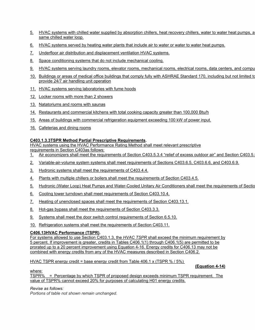
10. Buildings or areas of medical office buildings that comply fully with ASHRAE Standard 170, including but not limited toprovide 24/7 air handling unit operation
11. HVAC systems serving laboratories with fume hoods
12. Locker rooms with more than 2 showers
13. Natatoriums and rooms with saunas
14. Restaurants and commercial kitchens with total cooking capacity greater than 100,000 Btu/h
15. Areas of buildings with commercial refrigeration equipment exceeding 100 kW of power input.
16. Cafeterias and dining rooms
C403.1.3.3TSPR Method Partial Prescriptive Requirements. HVAC systems using the HVAC Performance Rating Method shall meet relevant prescriptive requirements in Section C403as follows: 1. Air economizers shall meet the requirements of Section C403.5.3.4 “relief of excess outdoor air” and Section C403.5.5
2. Variable-air-volume system systems shall meet requirements of Sections C403.6.5, C403.6.6, and C403.6.9.
3. Hydronic systems shall meet the requirements of C403.4.4.
4. Plants with multiple chillers or boilers shall meet the requirements of Section C403.4.5.
5. Hydronic (Water Loop) Heat Pumps and Water-Cooled Unitary Air Conditioners shall meet the requirements of Sectio
6. Cooling tower turndown shall meet requirements of Section C403.10.4.
7. Heating of unenclosed spaces shall meet the requirements of Section C403.13.1.
8. Hot-gas bypass shall meet the requirements of Section C403.3.3.
9. Systems shall meet the door switch control requirements of Section 6.5.10.
10. Refrigeration systems shall meet the requirements of Section C403.11.
C406.13HVAC Performance (TSPR). For systems allowed to use Section C403.1.3, the HVAC TSPR shall exceed the minimum requirement by 5 percent. If improvement is greater, credits in Tables C406.1(1) through C406.1(5) are permitted to be prorated up to a 20 percent improvement using Equation 4-16. Energy credits for C406.13 may not be combined with energy credits from any of the HVAC measures described in Section C406.2. HVAC TSPR energy credit = base energy credit from Table 406.1 x (TSPR % / 5%)
(Equation 4-14) where: TSPR% = Percentage by which TSPR of proposed design exceeds minimum TSPR requirement. The value of TSPR% cannot exceed 20% for purposes of calculating H01 energy credits.
Revise as follows: Portions of table not shown remain unchanged.

TABLE C406.1(1) ADDITIONAL ENERGY EFFICIENCY CREDITS FOR GROUP B OCCUPANCIES SECTION CLIMATE ZONE
0A & 1A 0B & 1B 2A 2B 3A 3B 3C 4A 4B 4C 5A 5B 5C 6A 6B 7 8
C406.13: HVAC TSPR 8 8 7 7 6 6 4 6 6 4 6 6 4 6 6 6 6
TABLE C406.1(2) ADDITIONAL ENERGY EFFICIENCY CREDITS FOR GROUP R AND I OCCUPANCIES SECTION CLIMATE ZONE
0A & 1A 0B & 1B 2A 2B 3A 3B 3C 4A 4B 4C 5A 5B 5C 6A 6B 7 8
C406.13: HVAC TSPR 8 8 8 7 6 6 5 6 6 4 6 5 4 6 6 6 7
. Portions of table not shown remain unchanged.
TABLE C406.1(3) ADDITIONAL ENERGY EFFICIENCY CREDITS FOR GROUP E OCCUPANCIES SECTION CLIMATE ZONE
0A & 1A 0B & 1B 2A 2B 3A 3B 3C 4A 4B 4C 5A 5B 5C 6A 6B 7 8
C406.13: HVAC TSPR 11 11 10 9 8 8 6 8 7 6 7 7 6 8 7 8 8
NA = Not Applicable. a. For schools with showers or full-service kitchens.
Portions of table not shown remain unchanged.
TABLE C406.1(4) ADDITIONAL ENERGY EFFICIENCY CREDITS FOR GROUP M OCCUPANCIES SECTION CLIMATE ZONE
0A & 1A 0B & 1B 2A 2B 3A 3B 3C 4A 4B 4C 5A 5B 5C 6A 6B 7 8
C406.13 HVAC TSPR 11 11 10 9 8 8 6 8 8 7 8 8 6 9 8 9 10
NA = Not Applicable. Portions of table not shown remain unchanged.
TABLE C406.1(5) ADDITIONAL ENERGY EFFICIENCY CREDITS FOR OTHERa OCCUPANCIES SECTION CLIMATE ZONE
0A & 1A 0B & 1B 2A 2B 3A 3B 3C 4A 4B 4C 5A 5B 5C 6A 6B 7 8
C406.13: HVAC TSPR 7 8 7 6 6 5 3 6 5 4 7 6 4 8 7 8 8
Add new Section C409 text as follows:
Section C409 Calculation of HVAC Total System Performance Ratio
C409.1Purpose. This appendix establishes criteria for demonstrating compliance with the requirements of C403.1.1, HVAC total system performance ratio (HVAC TSPR)
C409.2Scope.
This appendix applies to new HVAC systems that serve buildings in Section C403.1.3.1 and are not excluded from using HVAC TSPR by Section C403.1.3, and 1. serve office (including medical office), retail, library, hotel/motel, and education occupancies, or.
2. serve dwelling units and common areas within multifamily buildings.
All applicable HVAC systems shall comply with Section C409.
C409.2.1Core & Shell / Initial Build-Out, and Future System Construction Analysis.

Where the building permit applies to only a portion of the HVAC system in a building and the remaining components will be designed under a future building permit or were previously installed, the future or previously installed components shall be modeled as follows: 1. Where the HVAC zones that do not include HVAC systems in the current permit will be or are served
by independent systems, then the block including those zones shall not be included in the model.
2. Where the HVAC zones that do not include complete HVAC systems in the permit are intended to receive HVAC services from systems in the permit, their proposed zonal systems shall be modeled with equipment that meets, but does not exceed, the requirements of C403.
3. Where the zone equipment in the permit receives HVAC services from previously installed systems that are not in the permit, the previously installed systems shall be modeled with equipment matching the certified value of what is installed or equipment that meets the requirements of C403.
4. Where the central plant heating and cooling equipment is completely replaced and HVAC zones with existing systems receive HVAC services from systems in the permit, their proposed zonal systems shall be modeled with equipment that meets, but does not exceed, the requirements of Section C403.
Informative Note:
1. Examples of HVAC systems that are intended to receive HVAC services from systems in the permit include future zonal water source heat pumps that will receive loop water that is heated by a boiler or cooled by a cooling tower included in the permit, any system that will receive outdoor ventilation air from a dedicated outdoor air system included in the permit, and future zone terminal units that will be connected to a central VAV system included in the permit.
2. An initial build-out with heating coils served from a previously installed system with a high-efficiency condensing boiler would use the installed efficiency if it exceeded the current requirements. If the installed boiler had a lower efficiency than the current requirements, the current requirement would be used.
3. A partial central plant upgrade (e.g. chiller, but not boiler replacement) cannot use this method
C409.3Definitions. The definitions contained in this section supplement or modify the definitions in Section C202 of the International Energy Conservation Code. Add new definition as follows:
BLOCK. A generic concept used in energy simulation. It can include one or more thermal zones. It represents a whole building or portion of a building with the same use type served by the same HVAC system type.
HVAC TOTAL SYSTEM PERFORMANCE RATIO (HVAC TSPR).. The ratio of the sum of a building’s annual heating and cooling load in thousands of Btus to the sum of annual site energy consumption of the building HVAC systems in BTU.
PROPOSED DESIGN. A description of the proposed building used to estimate annual energy use for determining compliance based on total building performance and HVAC total system performance ratio.
STANDARD REFERENCE DESIGN. A version of the proposed design that meets the minimum requirements of this code and is used to determine the maximum annual energy use requirement for compliance based on total building performance and HVAC total system performance ratio. Add new text as follows:
C409.4HVAC TSPR Compliance.

Systems allowed to use HVAC TSPR in accordance with C403.1.3 shall comply with all of the following: 1. Systems shall meet the applicable provisions of Section C403.1.3.3 and Sections within Section C403
that are listed in Table C407.2
2 The HVAC TSPR of the proposed design shall be greater than or equal to the HVAC TSPR of the standard reference design divided by the mechanical performance factor (MPF)using Equation 4-16.
TSPRp > TSPRr / MPF (Equation 4-16)
where:
TSPRp = HVAC TSPR of the proposed design calculated in accordance with Sections C409.4, C409.5 and C409.6.
TSPRr = HVAC TSPR of the reference building design calculated in accordance with Sections C409.4, C409.5 and C409.6.
MPF = Mechanical Performance Factor from Table C409.4 based on climate zone and building use type
Where a building has multiple building use types, MPF shall be area weighted using Equation 4-17
MPF = (A1*MPF1 + A2* MPF2+...+An*MPFn)/(A1+A2+...+An) (Equation 4-17)
where:
MPF1, MPF2 through MPFn = Mechanical Performance Factors from Table C409.4 based on climate zone and building use types 1,2, through n
A1, A2 through An = Conditioned floor areas for building use types 1, 2, through n
Table C409.4 Mechanical Performance Factors Climate Zone:
Building type
Ocp. Group
0A 0B 1A 1B 2A 2B 3A 3B 3C 4A 4B 4C 5A 5B 5C 6A 6B 7 8
Office (small and medium)a
B 0.75 0.75 0.74 0.74 0.72 0.69 0.75 0.70 0.69 0.73 0.70 0.71 0.76 0.72 0.72 0.78 0.75 0.79 0.81
Office (Large)a
B 0.91 0.93 0.94 0.93 0.88 0.94 0.80 0.88 0.95 0.77 0.95 0.82 0.82 0.89 0.82 0.81 0.84 0.79 0.77
Retail M 0.61 0.59 0.52 0.56 0.48 0.47 0.43 0.46 0.62 0.53 0.60 0.73 0.57 0.68 0.75 0.60 0.60 0.57 0.52
Hotel/Motel R-1 0.62 0.62 0.63 0.63 0.62 0.68 0.61 0.69 0.73 0.59 0.66 0.65 0.55 0.59 0.68 0.51 0.54 0.47 0.40
Multi-Family/ Dormitory
R-2 0.64 0.63 0.67 0.63 0.65 0.64 0.59 0.60 0.54 0.59 0.57 0.52 0.58 0.53 0.48 0.57 0.53 0.55 0.52
School/ Education and Libraries
E (A-3)
0.89 0.89 0.89 0.87 0.83 0.82 0.79 0.80 0.80 0.75 0.85 0.77 0.84 0.83 0.73 0.86 0.82 0.83 0.78
a large office (gross conditioned floor area >150,000 ft2 (14,000 m2) or > 5 floors); all other offices are small or medium
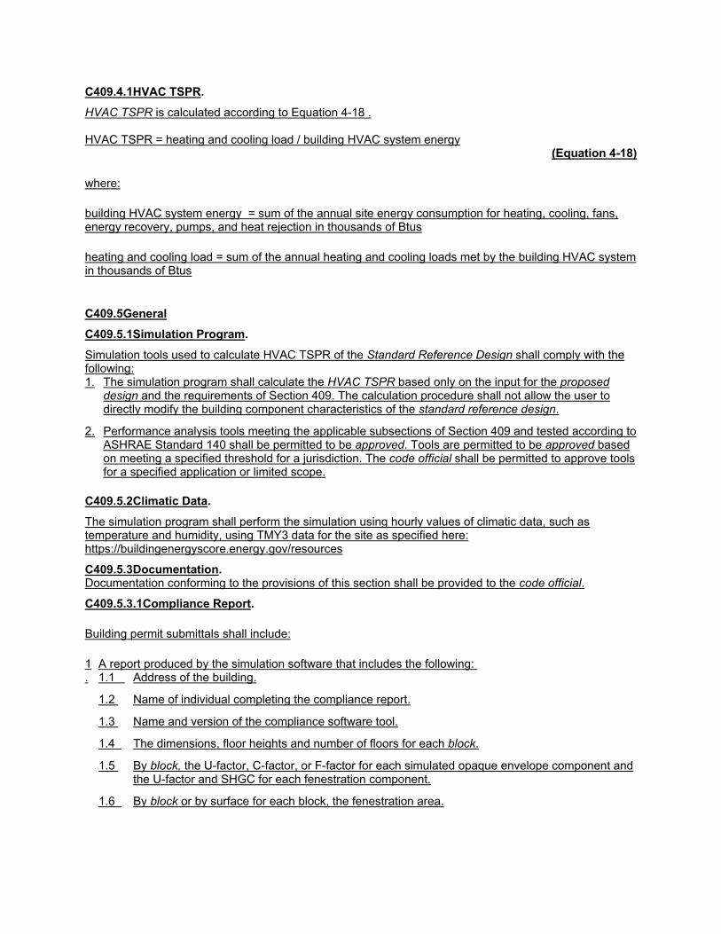
C409.4.1HVAC TSPR.
HVAC TSPR is calculated according to Equation 4-18 . HVAC TSPR = heating and cooling load / building HVAC system energy
(Equation 4-18)
where:
building HVAC system energy = sum of the annual site energy consumption for heating, cooling, fans, energy recovery, pumps, and heat rejection in thousands of Btus
heating and cooling load = sum of the annual heating and cooling loads met by the building HVAC system in thousands of Btus
C409.5General
C409.5.1Simulation Program.
Simulation tools used to calculate HVAC TSPR of the Standard Reference Design shall comply with the following: 1. The simulation program shall calculate the HVAC TSPR based only on the input for the proposed
design and the requirements of Section 409. The calculation procedure shall not allow the user to directly modify the building component characteristics of the standard reference design.
2. Performance analysis tools meeting the applicable subsections of Section 409 and tested according to ASHRAE Standard 140 shall be permitted to be approved. Tools are permitted to be approved based on meeting a specified threshold for a jurisdiction. The code official shall be permitted to approve tools for a specified application or limited scope.
C409.5.2Climatic Data.
The simulation program shall perform the simulation using hourly values of climatic data, such as temperature and humidity, using TMY3 data for the site as specified here: https://buildingenergyscore.energy.gov/resources
C409.5.3Documentation. Documentation conforming to the provisions of this section shall be provided to the code official.
C409.5.3.1Compliance Report.
Building permit submittals shall include:
1.
A report produced by the simulation software that includes the following: 1.1 Address of the building.
1.2 Name of individual completing the compliance report.
1.3 Name and version of the compliance software tool.
1.4 The dimensions, floor heights and number of floors for each block.
1.5 By block, the U-factor, C-factor, or F-factor for each simulated opaque envelope component and the U-factor and SHGC for each fenestration component.
1.6 By block or by surface for each block, the fenestration area.

1.7 By block, a list of the HVAC equipment simulated in the proposed design including the equipment type, fuel type, equipment efficiencies and system controls.
1.8 Annual site HVAC energy use by end use for the proposed and baseline building
1.9 Annual sum of heating and cooling loads for the baseline building.
1.10 The HVAC total system performance ratio for both the standard reference design and the proposed design.
2.
A mapping of the actual building HVAC component characteristics and those simulated in the proposed design showing how individual pieces of HVAC equipment identified above have been combined into average inputs as required by Section C409.6.1.10 including: 2.1 Fans
2.2 Hydronic pumps
2.3 Air handlers
2.4 Packaged cooling equipment
2.5 Furnaces
2.6 Heat pumps
2.7 Boilers
2.8 Chillers
2.9 Cooling towers
2.10 Electric resistance coils
2.11 Condensing units
2.12 Motors for fans and pumps
2.13 Energy recovery devices
For each piece of equipment identified above include the following as applicable:
1. Equipment name or tag consistent with that found on the design documents.
2. Rated Efficiency level.
3. Rated Capacity.
4. Electrical input power for fans and pumps (before any speed or frequency control device) at design condition and calculation of input value (W/cfm or W/gpm)
3.
Floor plan of the building identifying:
3.1 How portions of the buildings are assigned to the simulated blocks
3.2 Areas of the building that are not covered under the requirements of Section C403.1.1.
C409.6Calculation Procedures. Except as specified by this Section, the standard reference design and proposed design shall be configured and analyzed using identical methods and techniques

C409.6.1Simulation of the proposed building design. The proposed design shall be configured and analyzed as specified in this section.
C409.6.1.1Block Geometry.
The geometry of buildings shall be configured using one or more blocks. Each block shall define attributes including block dimensions, number of floors, floor to floor height and floor to ceiling height. Simulation software may allow the use of simplified shapes (such as rectangle, L shape, H Shape, U shape or T shape) to represent blocks. Where actual building shape does not match these pre-defined shapes, simplifications are permitted providing the following requirements are met: 1. The conditioned floor area and volume of each block shall match the proposed design within 10
percent.
2. The area of each exterior envelope component from Table C402.1.4 is accounted for within 10 percent of the actual design.
3. The area of vertical fenestration and skylights is accounted for within 10 percent of the actual design.
4. The orientation of each component in 2 and 3 above is accounted for within 45 degrees of the actual design.
The creation of additional blocks may be necessary to meet these requirements.
Exception: Portions of the building that are unconditioned or served by systems not covered by the requirements of Section C403.1.1 shall be omitted.
C409.6.1.1.1Number of Blocks.
One or more blocks may be required per building based on the following restrictions: 1. Each block can have only one occupancy type (multifamily dwelling unit, multifamily common area, office,
library, education, hotel/motel or retail). Therefore, at least one single block shall be created for each unique use type.
2. Each block can be served by only one type of HVAC system. Therefore, a single block shall be created for each unique HVAC system and use type combination. Multiple HVAC units of the same type may be represented in one block. Table D601.10.2 provides directions for combining multiple HVAC units or components of the same type into a single block.
3. Each block can have a single definition of floor to floor or floor to ceiling heights. Where floor heights differ by more than two feet, unique blocks should be created for the floors with varying heights.
4. Each block can include either above grade or below grade floors. For buildings with both above grade and below grade floors, separate blocks should be created for each. For buildings with floors partially above grade and partially below grade, if the total wall area of the floor(s) in consideration is greater than or equal to 50 percent above grade, then it should be simulated as a completely above grade block, otherwise it should be simulated as a below grade block.
5. Each wall on a façade of a block shall have similar vertical fenestration. The product of the proposed design U-factor times the area of windows (UA) on each façade of a given floor cannot differ by more than 15 percent of the average UA for that façade in each block. The product of the proposed design SHGC times the area of windows (SHGCA) on each façade of a given floor cannot differ by more than 15 percent of the average SHGCA for that façade in each block. If either of these conditions are not met, additional blocks shall be created consisting of floors with similar fenestration.
6. For a building model with multiple blocks, the blocks should be configured together to have the same adjacencies as the actual building design.
C409.6.1.2Thermal Zoning. Each floor in a block shall be modeled as a single thermal zone or as five thermal zones consisting of four perimeter zones and a core zone. Below grade floors shall be modeled as a single thermal block. If any

façade in the block is less than 45 feet in length, there shall only be a single thermal zone per floor. Otherwise each floor shall be modeled with five thermal zones. A perimeter zone shall be created extending from each façade to a depth of 15 feet. Where facades intersect, the zone boundary shall be formed by a 45 degree angle with the two facades. The remaining area or each floor shall be modeled as a core zone with no exterior walls.
C409.6.1.3Occupancy
C409.6.1.3.1Occupancy Type. The occupancy type for each block shall be consistent with the building area type as determined in accordance with C405.4.2.1. Portions of the building that are building area types other than multifamily dwelling unit, multifamily common area, office, school (education), library, or retail shall not be included in the simulation. Surfaces adjacent to such building portions shall be modeled as adiabatic in the simulation program.
C409.6.1.3.2Occupancy schedule, density, and heat gain.. The occupant density, heat gain, and schedule shall be for multifamily, office, retail, library, hotel/motel or school as specified by ASHRAE Standard 90.1 Normative Appendix C.
C409.6.1.4Envelope Components
C409.6.1.4.1Roofs.. Roofs will be modeled with insulation above a steel roof deck. The roof U-factor and area shall be modeled as in the proposed design. If different roof thermal properties are present in a single block, an area weighted U-factor shall be used. Roof solar absorptance shall be modeled at 0.70 and emittance at 0.90.
C409.6.1.4.2Above grade walls. Walls will be modeled as steel frame construction. The U-factor and area of above grade walls shall be modeled as in the proposed design. If different wall constructions exist on the façade of a block an area-weighted U-factor shall be used.
C409.6.1.4.3Below grade walls. The C-factor and area of below grade walls shall be modeled as in the proposed design. If different slab on grade floor constructions exist in a block, an area-weighted C- factor shall be used.
C409.6.1.4.4Above grade exterior floors.
Exterior floors shall be modeled as steel frame. The U-factor and area of floors shall be modeled as in the proposed design. If different wall constructions exist in the block an area-weighted U-factor shall be used.
C409.6.1.4.5Slab on grade floors. The F-factor and area of slab on grade floors shall be modeled as in the proposed design. If different below grade wall constructions exist in a block, an area-weighted F- factor shall be used.
C409.6.1.4.6Vertical Fenestration.. The window area and area weighted U-factor and SHGC shall be modeled for each façade based the proposed design. Each exterior surface in a block must comply with Section C409.6.1.1.1 item 5. Windows will be combined into a single window centered on each façade based on the area and sill height input by the user. When different U values, SHGC or sill heights exist on a single facade, area weighted average for each shall be input by the user.
C409.6.1.4.7Skylights.. The skylight area and area weighted U-factor and SHGC shall be modeled for each floor based the proposed design. Skylights will be combined into a single skylight centered on the roof of each zone based on the area input by the user
C409.6.1.4.8Exterior Shading.
Permanent window overhangs shall be modeled. When windows with and without overhangs or windows with different overhang projection factors exist on a façade, window width weighted projection factors shall be input by the user as follows.

Pavg = (A1 x Lo1 + A2 x Lo2...+ An x Lon) / (Lw1 + Lw2... + Lwn)
(Equation 4-19)
where:
Pavg = Average overhang projection modeled in the simulation tool
A = Distance measured horizontally from the furthest continuous extremity of any overhang, eave, or permanently attached shading device to the vertical surface of the glazing.
Lo = Length off the overhang
Lw = Length of the window
C409.6.1.5Lighting.. Interior lighting power density shall be equal to the allowance in Table C405.4.2(1) for multifamily, office, retail, library, or school. The lighting schedule shall be for multifamily, office, retail, library, or school as specified by ASHRAE Standard 90.1 Normative Appendix C. The impact of lighting controls is assumed to be captured by the lighting schedule and no explicit controls shall be modeled. Exterior lighting shall not be modeled.
C409.6.1.6Miscellaneous equipment..
The miscellaneous equipment schedule and power shall be for multifamily, office, retail, library, or school as specified by ASHRAE Standard 90.1 Normative Appendix C. The impact of miscellaneous equipment controls is assumed to be captured by the equipment schedule and no explicit controls shall be modeled.
Exceptions:
1. Multifamily dwelling units shall have a miscellaneous load density of 0.42 W/ft2
2. Multifamily common areas shall have a miscellaneous load density of 0 W/ft2
C409.6.1.7Elevators. Elevators shall not be modeled.
C409.6.1.8Service water heating equipment.. Service water heating shall not be modeled.
C409.6.1.9On-site renewable energy systems.. On-site Renewable Energy Systems shall not be modeled.
C409.6.1.10HVAC equipment.. HVAC systems shall meet the requirements of Section C403 Mechanical Systems.
C409.6.1.10.1Supported HVAC systems.. At a minimum, the HVAC systems shown in Table CD105.2.10.1 shall be supported by the simulation program.
TABLE C409.6.1.10.1 PROPOSED BUILDING HVAC SYSTEMS SUPPORTED BY HVAC TSPR SIMULATION SOFTWARE System No. System Name System Abbreviation
1 Packaged Terminal Air Conditioner PTAC
2 Packaged Terminal Air Heat Pump PTHP
3 Packaged Single Zone Gas Furnace PSZGF
4 Packaged Single Zone Heat Pump (air to air only) PSZHP
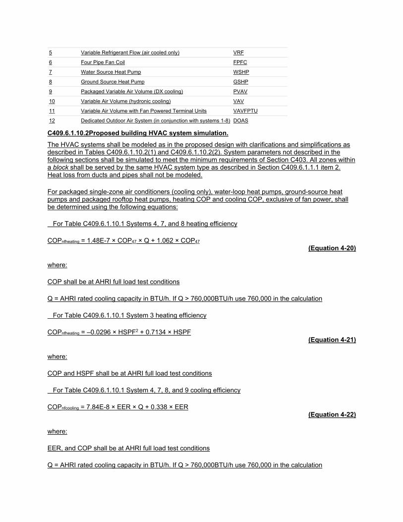
5 Variable Refrigerant Flow (air cooled only) VRF
6 Four Pipe Fan Coil FPFC
7 Water Source Heat Pump WSHP
8 Ground Source Heat Pump GSHP
9 Packaged Variable Air Volume (DX cooling) PVAV
10 Variable Air Volume (hydronic cooling) VAV
11 Variable Air Volume with Fan Powered Terminal Units VAVFPTU
12 Dedicated Outdoor Air System (in conjunction with systems 1-8) DOAS
C409.6.1.10.2Proposed building HVAC system simulation.
The HVAC systems shall be modeled as in the proposed design with clarifications and simplifications as described in Tables C409.6.1.10.2(1) and C409.6.1.10.2(2). System parameters not described in the following sections shall be simulated to meet the minimum requirements of Section C403. All zones within a block shall be served by the same HVAC system type as described in Section C409.6.1.1.1 item 2. Heat loss from ducts and pipes shall not be modeled.
For packaged single-zone air conditioners (cooling only), water-loop heat pumps, ground-source heat pumps and packaged rooftop heat pumps, heating COP and cooling COP, exclusive of fan power, shall be determined using the following equations:
For Table C409.6.1.10.1 Systems 4, 7, and 8 heating efficiency
COPnfheating = 1.48E-7 × COP47 × Q + 1.062 × COP47 (Equation 4-20)
where:
COP shall be at AHRI full load test conditions
Q = AHRI rated cooling capacity in BTU/h. If Q > 760,000BTU/h use 760,000 in the calculation
For Table C409.6.1.10.1 System 3 heating efficiency
COPnfheating = –0.0296 × HSPF2 + 0.7134 × HSPF (Equation 4-21)
where:
COP and HSPF shall be at AHRI full load test conditions
For Table C409.6.1.10.1 System 4, 7, 8, and 9 cooling efficiency
COPnfcooling = 7.84E-8 × EER × Q + 0.338 × EER (Equation 4-22)
where:
EER, and COP shall be at AHRI full load test conditions
Q = AHRI rated cooling capacity in BTU/h. If Q > 760,000BTU/h use 760,000 in the calculation

For Table C409.6.1.10.1 System 1 and 2 cooling efficiency
COPnfcooling = –0.0076 × SEER2 + 0.3796 × SEER (Equation 4-23)
where:
SEER and COP and HSPF shall be at AHRI full load test conditions.
For Table C409.6.1.10.1 System 1 and 2 cooling efficiency
COPnfcooling = 0.3322 × EER – 0.2145 (Equation 4-24)
where:
EER and COP shall be at AHRI full load test conditions
For Table C409.6.1.10.1 System 2 heating efficiency
COPnfheating = 1.1329 × COP – 0.214 (Equation 4-25)
where:
COP shall be at AHRI full load test conditions
Note to adopting authority: The following equations (in italics) are the SI version of Equations 4-20 through 4-25 and shall be used when adopting an SI version of the IECC.
(COPnfheating = 5.05E-4 × COPH8.3 × Q + 1.062 × COPH8.3) Equation 4-20 (SI)
(COPnfheating = –0.3446 × SCOPH2 + 2.434 × SCOPH) Equation 4-21(SI)
(COPnfcooling = 9.13E-4 × COPC × Q + 1.15 × COPC) Equation 4-22(SI)
(COPnfcooling = –0.0885 × SCOPC 2 + 1.295 × SCOPC) Equation 4-23(SI)
(COPnfcooling = 9.13E-4 × COPC × Q + 1.15 × COPC) Equation 4-24(SI)
(COPnfheating = 1.1329 × COP – 0.214) Equation 4-25(SI)
Where:EER, SEER, COP and HSPF shall be at AHRI full load test conditions Q = AHRI rated cooling capacity in BTU/h. If Q > 760,000BTU/h use 760,000 in the calculation.
Where multiple system components serve a block, average values weighed by the appropriate metric as described in this section shall be used.
1. Where multiple fan systems serve a single block, fan power shall be based on weighted average using the design supply air cfm

2. Where multiple cooling systems serve a single block, COP shall be based on a weighted average using cooling capacity. DX coils shall be entered as multi-stage if more than 50% of coil capacity serving the block is multi-stage with staged controls.
3. Where multiple heating systems serve a single block, thermal efficiency or heating COP shall be based on a weighted average using heating capacity.
4. Where multiple boilers or chillers serve a heating water or chilled water loop, efficiency shall be based on a weighted average for using heating or cooling capacity.
5. When multiple cooling towers serving a condenser water loop are combined, the cooling tower efficiency, cooling tower design approach and design range are based on a weighted average of the design water flow rate through each cooling tower.
6. Where multiple pumps serve a heating water, chilled water or condenser water loop, pump power shall be based on a weighted average for using design water flow rate.
7. When multiple system types with and without economizers are combined, the economizer maximum outside air fraction of the combined system shall be based on weighted average of 100% supply air for systems with economizers and design outdoor air for systems without economizers.
8. Multiple systems with and without ERVs cannot be combined.
9. Systems with and without supply air temperature reset cannot be combined.
10. Systems with different fan control (constant volume, multi-speed or VAV) for supply fans cannot be combined.
TABLE C409.6.1.10.2(1) PROPOSED BUILDING SYSTEM PARAMETERS Category Parameter Fixed or
User Defined
Required Applicable Systems
HVAC System Type
System Type User Defined
Selected from Table C409.6.1.10.1 All
System Sizing Design Day Information Fixed 99.6% heating design and 1% dry-bulb and 1% wet-bulb cooling design
All
Zone Coil Capacity Fixed Sizing factors used are 1.25 for heating equipment and 1.15 for cooling equipment
All
Supply Airflow Fixed Based on a supply-air-to-room-air temperature set-point difference of 20°F or
1-11
Fixed Equal to required outdoor air ventilation 12
Outdoor Ventilation Air
Portion of supply air with proposed Filter ≥MERV 13
User-defined
Percentage of supply air flow subject to higher filtration (Adjusts baseline Fan Power higher. Prorated)
All
Outdoor Ventilation Air Flow Rate
Fixed As specified in ASHRAE Standard 90.1 Normative Appendix C, adjusted for proposed DCV control
All
Outdoor Ventilation Supply Air Flow Rate Adjustments
Fixed Based on ASHRAE Standard 62.1 Section 6.2.4.3 System Ventilation Efficiency (Evs) is 0.75
9-11
Fixed System Ventilation Efficiency (Evs) is 1.0 1-8, 12
Fixed Basis is 1.0 Zone Air Distribution Effectiveness All
System Operation
Space temperature Set points Fixed As specified in ASHRAE Standard 90.1 Normative Appendix C, except multifamily which shall use 68 deg. F heating and 76 deg. F cooling setpoints
1-11
Fan Operation – Occupied
User Defined
Runs continuously during occupied hours or cycles to meet load.
Multispeed fans reduce airflow related to thermal loads.
1-11

Category Parameter Fixed or User Defined
Required Applicable Systems
Fan Operation – Occupied
Fixed Fan runs continuously during occupied hours
12
Fan Operation – Night Cycle Fixed Fan cycles on to meet setback temperatures 1-11
Packaged Equipment Efficiency
DX Cooling Efficiency User Defined
Cooling COP without fan energy calculated in accordance with Section C409.6.1.10.2
1, 2, 3, 4, 5,7, 8, 9, 11,12
DX Coil Number of Stages User-defined
Single Stage or Multistage 3, 4, 9
Heat Pump Efficiency User Defined
Heating COP without fan energy calculated in accordance with Section C409.6.1.10.2
2, 4, 5, 7, 8
Furnace Efficiency User Defined
Furnace thermal efficiencyc 3, 11
Heat Pump Supplemental Heat
Control Fixed Supplemental electric heat locked out above 40°F. Runs In conjunction with compressor between 40°F and 0°F.
2, 4
System Fan Power and Controls
Part-load Fan Controls User-defined
Constant volume or two speed 1-8
Part-load Fan Controlsa User-defined
Constant volume or variable air volume 12
Part-load Fan Controlsa Fixed Variable air volume. VFD with static pressure reset
9-11
Design Fan Power (W/cfm) User Defined
Input electric power for all fans in required to operate at fan system design conditions divided by the supply airflow rate
This is a “wire to air” value including all drive, motor efficiency and other losses.
All
Low-speed fan power User Defined
Low speed input electric power for all fans required to operate at low speed conditionsdivided by the low speed supply airflow rate. This is a “wire to air” value including all drive, motor efficiency and other losses.
1-8
Variable Air Volume Systems
Supply Air Temperature (SAT) Controls
User defined
If not SAT reset then constant at 55°F.
Options for reset based on outside air temperature (OAT) or warmest zone.
If warmest zone, then the user can specify the minimum and maximum temperatures.
If OAT reset, SAT is reset higher to 60°F at outdoor low of 50°F. SAT is 55°F at outdoor high of 70°F.
9, 10, 11
Minimum Terminal Unit airflow percentage
User Defined
Average minimum terminal unit airflow percentage for block weighted by cfm or minimum required for outdoor air ventilation, whichever is higher.
9, 10, 11
Terminal Unit Heating Source User Defined
Electric or hydronic 9, 10, 11
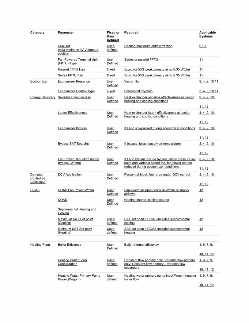
Category Parameter Fixed or User Defined
Required Applicable Systems
Dual set point minimum VAV damper position
User-defined
Heating maximum airflow fraction 9,10.
Fan Powered Terminal Unit (FPTU) Type
User Defined
Series or parallel FPTU 11
Parallel FPTU Fan Fixed Sized for 50% peak primary air at 0.35 W/cfm 11
Series FPTU Fan Fixed Sized for 50% peak primary air at 0.35 W/cfm 11
Economizer Economizer Presence User Defined
Yes or No 3, 4, 9, 10,11
Economizer Control Type Fixed Differential dry-bulb 3, 4, 9, 10,11
Energy Recovery Sensible Effectiveness User Defined
Heat exchanger sensible effectiveness at design heating and cooling conditions
3, 4, 9, 10,
11, 12
Latent Effectiveness User Defined
Heat exchanger latent effectiveness at design heating and cooling conditions
3, 4, 9, 10,
11, 12
Economizer Bypass User Defined
If ERV is bypassed during economizer conditions 3, 4, 9, 10,
11, 12
Bypass SAT Setpoint User Defined
If bypass, target supply air temperature 3, 4, 9, 10,
11, 12
Fan Power Reduction during Bypass (W/cfm)
User Defined
If ERV system include bypass, static pressure set point and variable speed fan, fan power can be reduced during economizer conditions
3, 4, 9, 10,
11, 12
Demand Controlled Ventilation
DCV Application User Defined
Percent of block floor area under DCV control 3, 4, 9, 10,
11, 12
DOAS DOAS Fan Power W/cfm User Defined
Fan electrical input power in W/cfm of supply airflowa
12
DOAS
Supplemental Heating and Cooling
User Defined
Heating source, cooling source 12
Maximum SAT Set point (Cooling)
User-defined
SAT set point if DOAS includes supplemental cooling
12
Minimum SAT Set point (Heating)
User-defined
SAT set point if DOAS includes supplemental heating
12
Heating Plant Boiler Efficiency User Defined
Boiler thermal efficiency 1, 6, 7, 9,
10, 11, 12
Heating Water Loop Configuration
User-defined
Constant flow primary only; Variable flow primary only; Constant flow primary – variable flow secondary
1, 6, 7, 9,
10, 11, 12
Heating Water Primary Pump Power (W/gpm)
User-defined
Heating water primary pump input W/gpm heating water flow
1, 6, 7, 9,
10, 11, 12

Category Parameter Fixed or User Defined
Required Applicable Systems
Heating Water Secondary Pump Power (W/gpm)
User-defined
Heating water secondary pump input W/gpm heating water flow (if primary/secondary)
1, 6, 7, 9,
10, 11, 12
Heating Water Loop Temperature
Fixed 180°F supply, 130°F return 1, 6, 9,
10,11
Boiler Type Fixed Non-condensing boiler where input thermal efficiency is less than 86%; Condensing boiler otherwise
1, 6, 7, 9,
10, 11, 12
Chilled Water Plant
Chiller Compressor Type User Defined
Screw/Scroll, Centrifugal or Reciprocating 6,1 0, 11,
12
Chiller Condenser Type User Defined
Air cooled or water cooled 6, 10, 11,
12
Chiller Full Load Efficiency User Defined
Chiller COP 6, 10, 11,
12
Chilled Water Loop Configuration
User Defined
Variable flow primary only, constant flow primary – variable flow secondary
6, 10, 11,12
Chilled Water Primary Pump Power (W/gpm)
User-defined
Primary pump input W/gpm chilled water flow 6, 10, 11,12
Chilled Water Secondary Pump Power (W/gpm)
User-defined
Secondary Pump input W/gpm chilled water flow (if primary/secondary)
6, 10, 11,12
Chilled Water Temperature Reset Included
User Defined
Yes/No 6, 10, 11,12
Chilled Water Plant (cont.)
Chilled Water Temperature Reset Schedule (if included)
Fixed Outdoor air reset: CHW supply temperature of 44°F at 80°F outdoor air dry bulb and above, CHW supply temperature of 54°F at 60°F outdoor air dry bulb temperature and below, ramped linearly between
6, 10, 11,12
Condenser Water Pump Power (W/gpm)
User Defined
Pump input W/gpm condenser water flow 6, 7, 8, ,10, 11, 12
Condenser Water Pump Control User Defined
Constant speed or variable speed 6, 7, 8, 10, 11,12
Cooling Tower Efficiency User Defined
gpm/hp tower fan 6, 7, 10, 11,12
Cooling Tower Fan Control User Defined
Constant or variable speed 6, 7, 10, 11,12
Cooling Tower Approach and Range
User Defined
Design cooling tower approach and range temperature
6, 7, 10, 11,12
Heat Pump Loop Flow Control
Loop flow and Heat Pump Control Valve
Fixed Two position Valve with VFD on Pump. Loop flow at 3 gpm/ton
7, 8
Heat Pump Loop Temperature Control
Fixed Set to maintain temperature between 50°F and 70°F
7
GLHP Well Field Fixed Bore depth = 250’
Bore length 200’/ton for greater of cooling or heating load
8

Category Parameter Fixed or User Defined
Required Applicable Systems
Bore spacing = 15’ Bore diameter = 5”
¾” Polyethylene pipe
Ground and grout conductivity =
4.8 Btu-in/h-ft2-0F
a. Part load fan power and pump power modified in accordance with Table C409.6.1.10.2(2)
TABLE C409.6.1.10.2(2) FAN AND PUMP Power CURVE COEFFICIENTS Equation Term
Fan Power Coefficients Pump Power Coefficients
VSD + SP reset Ride Pump Curve VSD + DP/valve reset
b 0.0408 0 0
x 0.088 3.2485 0.0205
x2 -0.0729 -4.7443 0.4101
x3 0.9437 2.5295 0.5753
C409.6.1.10.3Demand Control Ventilation.. Demand Controlled Ventilation (DCV) shall be modeled using a simplified approach that adjusts the design outdoor supply air flow rate based on the area of the building that is covered by DCV.
C409.6.2Simulation of the standard reference design. The standard reference design shall be configured and analyzed as specified in this section.
C409.6.2.1Utility Rates. Same as proposed.
C409.6.2.2Blocks. Same as proposed.
C409.6.2.3Thermal zoning. Same as proposed.
C409.6.2.4Occupancy type, schedule, density, and heat gain. Same as proposed
C409.6.2.5Envelope components.. Same as proposed.
C409.6.2.6Lighting. Same as proposed.
C409.6.2.7Miscellaneous equipment. Same as proposed.
C409.6.2.8Elevators. Not modeled. Same as proposed.
C409.6.2.9Service water heating equipment. Not modeled. Same as proposed.
C409.6.2.10On-site renewable energy systems. Not modeled. Same as proposed.
C409.6.2.11HVAC equipment.
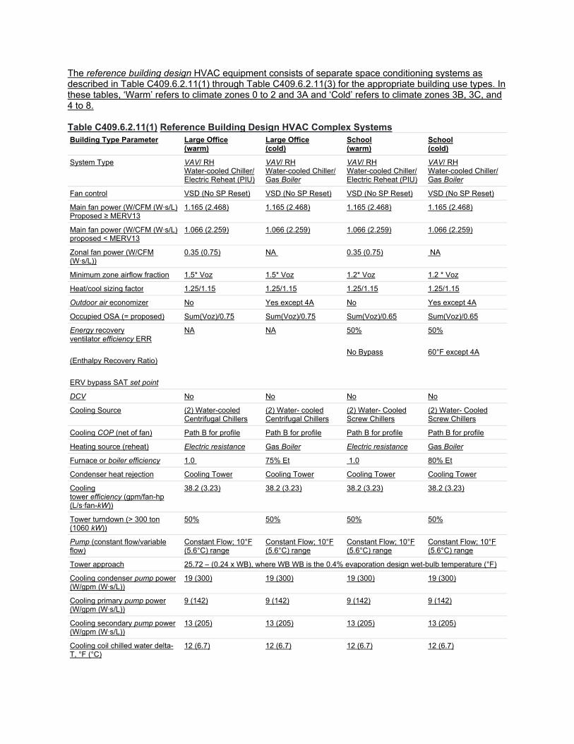
The reference building design HVAC equipment consists of separate space conditioning systems as described in Table C409.6.2.11(1) through Table C409.6.2.11(3) for the appropriate building use types. In these tables, ‘Warm’ refers to climate zones 0 to 2 and 3A and ‘Cold’ refers to climate zones 3B, 3C, and 4 to 8. Table C409.6.2.11(1) Reference Building Design HVAC Complex Systems Building Type Parameter Large Office
(warm) Large Office (cold)
School (warm)
School (cold)
System Type VAV/ RH Water-cooled Chiller/ Electric Reheat (PIU)
VAV/ RH Water-cooled Chiller/ Gas Boiler
VAV/ RH Water-cooled Chiller/ Electric Reheat (PIU)
VAV/ RH Water-cooled Chiller/ Gas Boiler
Fan control VSD (No SP Reset) VSD (No SP Reset) VSD (No SP Reset) VSD (No SP Reset)
Main fan power (W/CFM (W∙s/L) Proposed ≥ MERV13
1.165 (2.468) 1.165 (2.468) 1.165 (2.468) 1.165 (2.468)
Main fan power (W/CFM (W∙s/L) proposed < MERV13
1.066 (2.259) 1.066 (2.259) 1.066 (2.259) 1.066 (2.259)
Zonal fan power (W/CFM (W∙s/L))
0.35 (0.75) NA 0.35 (0.75) NA
Minimum zone airflow fraction 1.5* Voz 1.5* Voz 1.2* Voz 1.2 * Voz
Heat/cool sizing factor 1.25/1.15 1.25/1.15 1.25/1.15 1.25/1.15
Outdoor air economizer No Yes except 4A No Yes except 4A
Occupied OSA (= proposed) Sum(Voz)/0.75 Sum(Voz)/0.75 Sum(Voz)/0.65 Sum(Voz)/0.65
Energy recovery ventilator efficiency ERR
(Enthalpy Recovery Ratio)
ERV bypass SAT set point
NA NA 50%
No Bypass
50%
60°F except 4A
DCV No No No No
Cooling Source (2) Water-cooled Centrifugal Chillers
(2) Water- cooled Centrifugal Chillers
(2) Water- Cooled Screw Chillers
(2) Water- Cooled Screw Chillers
Cooling COP (net of fan) Path B for profile Path B for profile Path B for profile Path B for profile
Heating source (reheat) Electric resistance Gas Boiler Electric resistance Gas Boiler
Furnace or boiler efficiency 1.0 75% Et 1.0 80% Et
Condenser heat rejection Cooling Tower Cooling Tower Cooling Tower Cooling Tower
Cooling tower efficiency (gpm/fan-hp (L/s∙fan-kW))
38.2 (3.23) 38.2 (3.23) 38.2 (3.23) 38.2 (3.23)
Tower turndown (> 300 ton (1060 kW))
50% 50% 50% 50%
Pump (constant flow/variable flow)
Constant Flow; 10°F (5.6°C) range
Constant Flow; 10°F (5.6°C) range
Constant Flow; 10°F (5.6°C) range
Constant Flow; 10°F (5.6°C) range
Tower approach 25.72 – (0.24 x WB), where WB WB is the 0.4% evaporation design wet-bulb temperature (°F)
Cooling condenser pump power (W/gpm (W∙s/L))
19 (300) 19 (300) 19 (300) 19 (300)
Cooling primary pump power (W/gpm (W∙s/L))
9 (142) 9 (142) 9 (142) 9 (142)
Cooling secondary pump power (W/gpm (W∙s/L))
13 (205) 13 (205) 13 (205) 13 (205)
Cooling coil chilled water delta-T, °F (°C)
12 (6.7) 12 (6.7) 12 (6.7) 12 (6.7)
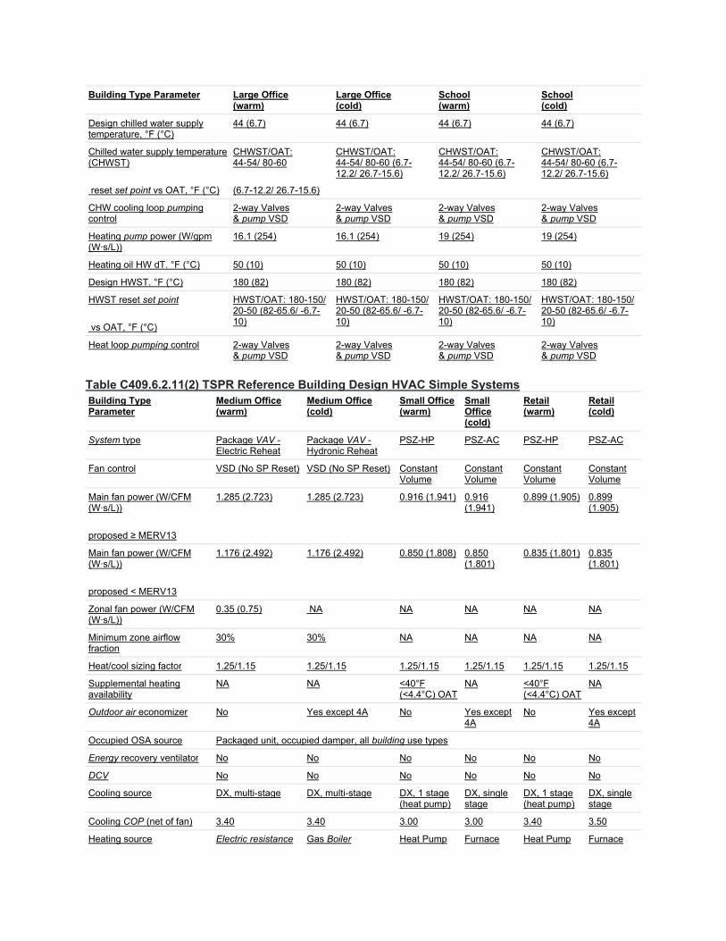
Building Type Parameter Large Office (warm)
Large Office (cold)
School (warm)
School (cold)
Design chilled water supply temperature, °F (°C)
44 (6.7) 44 (6.7) 44 (6.7) 44 (6.7)
Chilled water supply temperature (CHWST)
reset set point vs OAT, °F (°C)
CHWST/OAT: 44-54/ 80-60
(6.7-12.2/ 26.7-15.6)
CHWST/OAT: 44-54/ 80-60 (6.7-12.2/ 26.7-15.6)
CHWST/OAT: 44-54/ 80-60 (6.7-12.2/ 26.7-15.6)
CHWST/OAT: 44-54/ 80-60 (6.7-12.2/ 26.7-15.6)
CHW cooling loop pumping control
2-way Valves & pump VSD
2-way Valves & pump VSD
2-way Valves & pump VSD
2-way Valves & pump VSD
Heating pump power (W/gpm (W∙s/L))
16.1 (254) 16.1 (254) 19 (254) 19 (254)
Heating oil HW dT. °F (°C) 50 (10) 50 (10) 50 (10) 50 (10)
Design HWST. °F (°C) 180 (82) 180 (82) 180 (82) 180 (82)
HWST reset set point
vs OAT, °F (°C)
HWST/OAT: 180-150/ 20-50 (82-65.6/ -6.7-10)
HWST/OAT: 180-150/ 20-50 (82-65.6/ -6.7-10)
HWST/OAT: 180-150/ 20-50 (82-65.6/ -6.7-10)
HWST/OAT: 180-150/ 20-50 (82-65.6/ -6.7-10)
Heat loop pumping control 2-way Valves & pump VSD
2-way Valves & pump VSD
2-way Valves & pump VSD
2-way Valves & pump VSD
Table C409.6.2.11(2) TSPR Reference Building Design HVAC Simple Systems Building Type Parameter
Medium Office (warm)
Medium Office (cold)
Small Office (warm)
Small Office (cold)
Retail (warm)
Retail (cold)
System type Package VAV - Electric Reheat
Package VAV - Hydronic Reheat
PSZ-HP PSZ-AC PSZ-HP PSZ-AC
Fan control VSD (No SP Reset) VSD (No SP Reset) Constant Volume
Constant Volume
Constant Volume
Constant Volume
Main fan power (W/CFM (W∙s/L))
proposed ≥ MERV13
1.285 (2.723) 1.285 (2.723) 0.916 (1.941) 0.916 (1.941)
0.899 (1.905) 0.899 (1.905)
Main fan power (W/CFM (W∙s/L))
proposed < MERV13
1.176 (2.492) 1.176 (2.492) 0.850 (1.808) 0.850 (1.801)
0.835 (1.801) 0.835 (1.801)
Zonal fan power (W/CFM (W∙s/L))
0.35 (0.75) NA NA NA NA NA
Minimum zone airflow fraction
30% 30% NA NA NA NA
Heat/cool sizing factor 1.25/1.15 1.25/1.15 1.25/1.15 1.25/1.15 1.25/1.15 1.25/1.15
Supplemental heating availability
NA NA <40°F (<4.4°C) OAT
NA <40°F (<4.4°C) OAT
NA
Outdoor air economizer No Yes except 4A No Yes except 4A
No Yes except 4A
Occupied OSA source Packaged unit, occupied damper, all building use types
Energy recovery ventilator No No No No No No
DCV No No No No No No
Cooling source DX, multi-stage DX, multi-stage DX, 1 stage (heat pump)
DX, single stage
DX, 1 stage (heat pump)
DX, single stage
Cooling COP (net of fan) 3.40 3.40 3.00 3.00 3.40 3.50
Heating source Electric resistance Gas Boiler Heat Pump Furnace Heat Pump Furnace
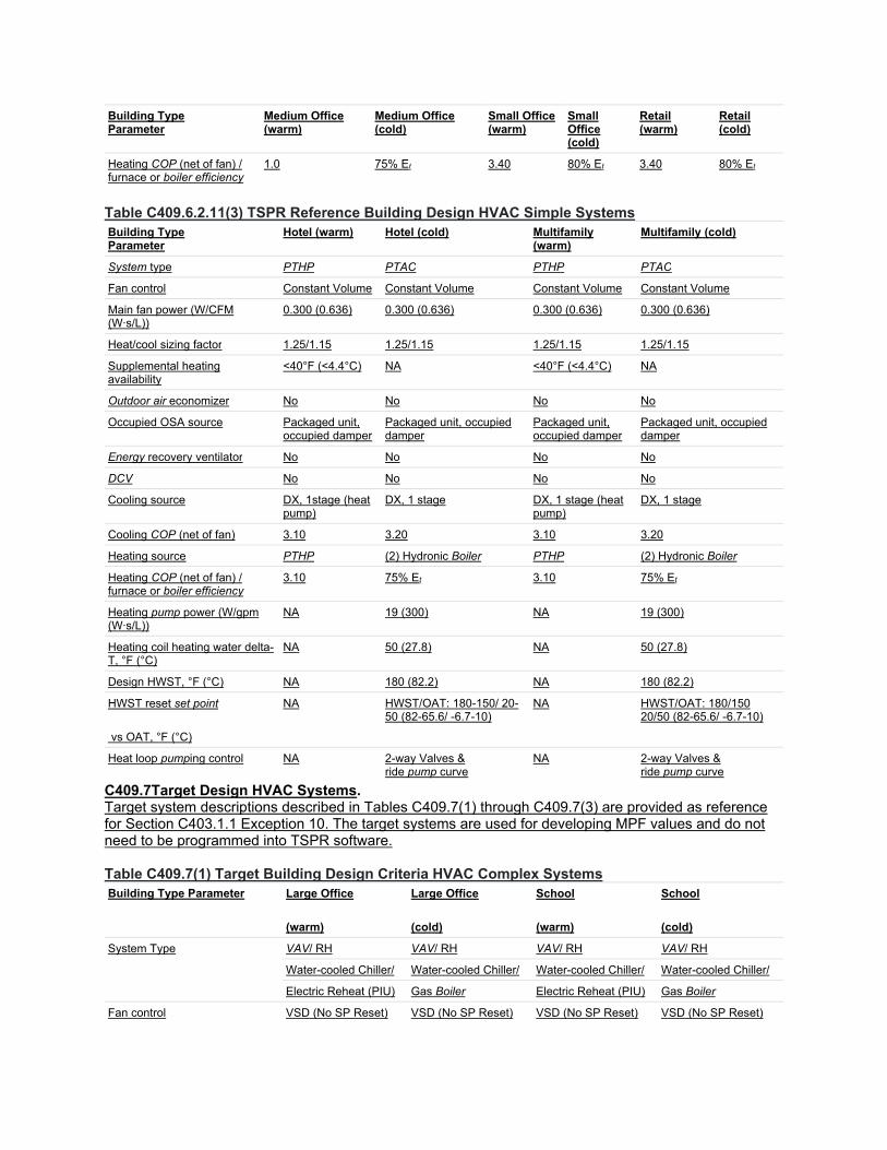
Building Type Parameter
Medium Office (warm)
Medium Office (cold)
Small Office (warm)
Small Office (cold)
Retail (warm)
Retail (cold)
Heating COP (net of fan) / furnace or boiler efficiency
1.0 75% Et 3.40 80% Et 3.40 80% Et
Table C409.6.2.11(3) TSPR Reference Building Design HVAC Simple Systems Building Type Parameter
Hotel (warm) Hotel (cold) Multifamily (warm)
Multifamily (cold)
System type PTHP PTAC PTHP PTAC
Fan control Constant Volume Constant Volume Constant Volume Constant Volume
Main fan power (W/CFM (W∙s/L))
0.300 (0.636) 0.300 (0.636) 0.300 (0.636) 0.300 (0.636)
Heat/cool sizing factor 1.25/1.15 1.25/1.15 1.25/1.15 1.25/1.15
Supplemental heating availability
<40°F (<4.4°C) NA <40°F (<4.4°C) NA
Outdoor air economizer No No No No
Occupied OSA source Packaged unit, occupied damper
Packaged unit, occupied damper
Packaged unit, occupied damper
Packaged unit, occupied damper
Energy recovery ventilator No No No No
DCV No No No No
Cooling source DX, 1stage (heat pump)
DX, 1 stage DX, 1 stage (heat pump)
DX, 1 stage
Cooling COP (net of fan) 3.10 3.20 3.10 3.20
Heating source PTHP (2) Hydronic Boiler PTHP (2) Hydronic Boiler
Heating COP (net of fan) / furnace or boiler efficiency
3.10 75% Et 3.10 75% Et
Heating pump power (W/gpm (W∙s/L))
NA 19 (300) NA 19 (300)
Heating coil heating water delta-T, °F (°C)
NA 50 (27.8) NA 50 (27.8)
Design HWST, °F (°C) NA 180 (82.2) NA 180 (82.2)
HWST reset set point
vs OAT, °F (°C)
NA HWST/OAT: 180-150/ 20-50 (82-65.6/ -6.7-10)
NA HWST/OAT: 180/150 20/50 (82-65.6/ -6.7-10)
Heat loop pumping control NA 2-way Valves & ride pump curve
NA 2-way Valves & ride pump curve
C409.7Target Design HVAC Systems. Target system descriptions described in Tables C409.7(1) through C409.7(3) are provided as reference for Section C403.1.1 Exception 10. The target systems are used for developing MPF values and do not need to be programmed into TSPR software. Table C409.7(1) Target Building Design Criteria HVAC Complex Systems Building Type Parameter Large Office
(warm)
Large Office
(cold)
School
(warm)
School
(cold)
System Type VAV/ RH VAV/ RH VAV/ RH VAV/ RH
Water-cooled Chiller/ Water-cooled Chiller/ Water-cooled Chiller/ Water-cooled Chiller/
Electric Reheat (PIU) Gas Boiler Electric Reheat (PIU) Gas Boiler
Fan control VSD (No SP Reset) VSD (No SP Reset) VSD (No SP Reset) VSD (No SP Reset)

Building Type Parameter Large Office
(warm)
Large Office
(cold)
School
(warm)
School
(cold)
Main fan power (W/CFM (W∙s/L) Proposed ≥ MERV13
1.127 (2.388) 1.127 (2.388) 1.127 (2.388) 1.127 (2.388)
Zonal fan power (W/CFM (W∙s/L))
0.35 (0.75) NA 0.35 (0.75) NA
Minimum zone airflow fraction 1.5* Voz 1.5* Voz 1.2* Voz 1.2 * Voz
Heat/cool sizing factor 1.25/1.15 1.25/1.15 1.25/1.15 1.25/1.15
Outdoor air economizer Yes except 0-1 Yes Yes except 0-1 Yes
Occupied OSA (= proposed) Sum(Voz)/0.75 Sum(Voz)/0.75 Sum(Voz)/0.65 Sum(Voz)/0.65
Energy recovery ventilator efficiency ERR
NA NA 50% 50%
(Enthalpy Recovery Ratio) No Bypass 60°F except 4A
ERV bypass SAT set point
DCV Yes Yes Yes Yes
% Area Variable Control 15% 15% 70% 70%
% Area On/Off Control 65% 65% 20% 20%
Cooling Source (2) Water-cooled Centrif Chillers
(2) Water- cooled Centrif Chillers
(2) Water- Cooled Screw Chillers
(2) Water- Cooled Screw Chillers
Cooling COP (net of fan) Path B for profile Path B for profile Path B for profile Path B for profile
Heating source (reheat) Electric resistance Gas Boiler Electric resistance Gas Boiler
Furnace or boiler efficiency 1.0 90% Et 1.0 80% Et
Condenser heat rejection Cooling Tower Cooling Tower Cooling Tower Cooling Tower
Cooling tower efficiency (gpm/hp (L/s∙kW))—See G3.1.3.11
40.2 (3.40) 40.2 (3.40) 40.2 (3.40) 40.2 (3.40)
Tower turndown (> 300 ton (1060 kW))
50% 50% 50% 50%
Pump (constant flow/variable flow)
Constant Flow; 10°F (5.6°C) range
Constant Flow; 10°F (5.6°C) range
Constant Flow; 10°F (5.6°C) range
Constant Flow; 10°F (5.6°C) range
Tower approach G3.1.3.11 G3.1.3.11 G3.1.3.11 G3.1.3.11
Cooling condenser pump power (W/gpm (W∙s/L))
19 (300) 19 (300) 19 (300) 19 (300)
Cooling primary pump power (W/gpm (W∙s/L))
9 (142) 9 (142) 9 (142) 9 (142)
Cooling secondary pump power (W/gpm (W∙s/L))
13 (205) 13 (205) 13 (205) 13 (205)
Cooling coil chilled water delta-T, °F (°C)
18 (10) 18 (10) 18 (10) 18 (10)
Design chilled water supply temperature, °F (°C)
42 (5.56) 42 (5.56) 42 (5.56) 42 (5.56)
Chilled water supply temperature (CHWST)
CHWST/OAT: CHWST/OAT: CHWST/OAT: CHWST/OAT:
reset set point vs OAT, °F (°C) 44-54/ 80-60 44-54/ 80-60 (6.7-12.2/ 26.7-15.6) (see Apx G)
44-54/ 80-60 (6.7-12.2/ 26.7-15.6) (see Apx G)
44-54/ 80-60 (6.7-12.2/ 26.7-15.6) (see Apx G)
(6.7-12.2/ 26.7-15.6) (see Apx G)
CHW cooling loop pumping control
2-way Valves & pump VSD
2-way Valves & pump VSD
2-way Valves & pump VSD
2-way Valves & pump VSD

Building Type Parameter Large Office
(warm)
Large Office
(cold)
School
(warm)
School
(cold)
Heating pump power (W/gpm (W∙s/L))
16.1 (254) 16.1 (254) 19 (254) 19 (254)
Heating HW dT. °F (°C) 50 (27.78) 20 (11.11) 50 (27.78) 20 (11.11)
Design HWST. °F (°C) 180 (82) 140 (60) 180 (82) 140 (60)
HWST reset set point HWST/OAT: 180-150/ 20-50 (82-65.6/ -6.7-10)
HWST/OAT: 180-150/ 20-50 (82-65.6/ -6.7-10)
HWST/OAT: 180-150/ 20-50 (82-65.6/ -6.7-10)
HWST/OAT: 180-150/ 20-50 (82-65.6/ -6.7-10) vs OAT, °F (°C)
Heat loop pumping control 2-way Valves & pump VSD
2-way Valves & pump VSD
2-way Valves & pump VSD
2-way Valves & pump VSD
Table C409.7(2) Target Building Design Criteria HVAC Simple Systems Building Type Medium Office
(warm) Medium Office (cold) Small Office
(warm) Small Office (cold)
Retail (warm) Retail (cold)
Parameter
System type Package VAV - Electric Reheat
Package VAV - Hydronic Reheat
PSZ-HP PSZ-AC PSZ-HP PSZ-AC
Fan control VSD (No SP Reset)
VSD (No SP Reset) Constant Volume
Constant Volume
2-speed 2-speed
Main fan power (W/CFM (W∙s/L))
0.634 (1.343) 0.634 (1.343) 0.486 (1.03) 0.486 (1.03) 0.585 (1.245) 0.585 (1.245)
proposed ≥ MERV13
Zonal fan power (W/CFM (W∙s/L))
0.35 (5.53) NA NA NA NA NA
Minimum zone airflow fraction
1.5* Voz 1.5* Voz NA NA NA NA
Heat/cool sizing factor 1.25/1.15 1.25/1.15 1.25/1.15 1.25/1.15 1.25/1.15 1.25/1.15
Supplemental heating availability
NA NA <40°F (<4.4°C) OAT
NA <40°F (<4.4°C) OAT
NA
Outdoor air economizer Yes except 0-1 Yes Yes except 0-1
Yes Yes except 0-1
Yes
Occupied OSA source Packaged unit, occupied damper, all building use types
Energy recovery ventilator No No No No Yes, in 0A, 1A, 2A, 3A
Yes all A, 6,7,8 CZ
ERR 50% 50%
DCV Yes Yes No No Yes Yes
% Area Variable Control 15% 15% 80% 80%
% Area On/Off Control 65% 65% 0% 0%
Cooling source DX, multi-stage DX, multi-stage DX, 1 stage (heat pump)
DX, single stage
DX, 2 stage (heat pump)
DX, 2 stage
Cooling COP (net of fan) 3.83 3.83 3.82 3.8248 3.765 3.765
Heating source Electric resistance
Gas Boiler Heat Pump Furnace Heat Pump Furnace
Heating COP (net of fan) / furnace or boiler efficiency
100% 81% Et 3.81 81% Et 3.536 81% Et
Heating coil HW dT. °F (°C)
NA 20 (11.11) NA NA NA NA
Design HWST. °F (°C) NA 140 (60) NA NA NA NA
HWST reset set point NA NA NA NA NA

Building Type Medium Office (warm)
Medium Office (cold) Small Office (warm)
Small Office (cold)
Retail (warm) Retail (cold)
Parameter
vs OAT, °F (°C) HWST/OAT: 180-150/ 20-50 (82-65.6/ -6.7-10)
Heat loop pumping control NA 2-way Valves & ride pump curve
NA NA NA NA
Heating pump power (W/gpm (W∙s/L))
NA 16.1 NA NA NA NA
Table C409.7(3) Target Building Design Criteria HVAC Simple Systems Building Type Hotel (warm) Hotel (cold) Multifamily
(warm) Multifamily (cold)
Parameter
System type PTHP PTAC with Hydronic Boiler Split HP Split AC
Fan control Cycling Cycling Cycling Cycling
Main fan power (W/CFM (W∙s/L)) 0.300 (0.638) 0.300 (0.638) 0.246 (0.523) 0.271 (0.576)
Heat/cool sizing factor 1.25/1.15 1.25/1.15 1.25/1.15 1.25/1.15
Supplemental heating availability <40°F (<4.4°C) NA <40°F (<4.4°C) NA
Outdoor air economizer Only CZ 2, 3 No No No
Occupied OSA source DOAS DOAS DOAS DOAS except 3C
Energy recovery ventilator NA NA Yes Yes except 3C
DCV Yes Yes No No
% Area Variable Control 70% 70%
% Area On/Off Control 0% 0%
Cooling source DX, 1stage (heat pump)
DX, 1 stage DX, 1 stage (heat pump)
DX, 1 stage
Cooling COP (net of fan) 3.83 3.83 3.823 3.6504
Heating source Heat Pump (2) Hydronic Boiler Heat Pump Furnace
Heating COP (net of fan) / furnace or boiler efficiency
3.44 81% Et 3.86 80% AFUE
Heating pump power (W/gpm (W∙s/L)) NA 16.1 NA NA
Heating coil heating water delta-T, °F (°C)
NA 20 (11.11) NA NA
Design HWST, °F (°C) NA 140 (60) NA NA
HWST reset set point NA HWST/OAT: 180-150/ 20-50 (82-65.6/ -6.7-10)
NA NA
vs OAT, °F (°C)
Heat loop pumping control NA 2-way Valves & ride pump curve NA NA
Add new Appendix CD as follows:
Appendix CD REQUIRED HVAC TSPR
CD 101Required HVAC TSPR.
For jurisdictions who wish to adopt a stretch code or HVAC incentive system, make the following changes to Section C403.
Replace Section C403.1 with the following:
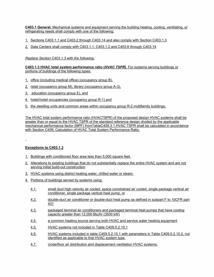
C403.1 General. Mechanical systems and equipment serving the building heating, cooling, ventilating, or refrigerating needs shall comply with one of the following:
1. Sections C403.1.1 and C403.2 through C403.14 and also comply with Section C403.1.3
2. Data Centers shall comply with C403.1.1, C403.1.2 and C403.6 through C403.14
Replace Section C403.1.3 with the following.
C403.1.3 HVAC total system performance ratio (HVAC TSPR). For systems serving buildings or portions of buildings of the following types:
1. office (including medical office) (occupancy group B),
2. retail (occupancy group M), library (occupancy group A-3),
3. education (occupancy group E), and
4. hotel/motel occupancies (occupancy group R-1) and
5. the dwelling units and common areas within occupancy group R-2 multifamily buildings,
The HVAC total system performance ratio (HVACTSPR) of the proposed design HVAC systems shall be greater than or equal to the HVAC TSPR of the standard reference design divided by the applicable mechanical performance factor (MPF) fromTableC409.3.1.HVAC TSPR shall be calculated in accordance with Section C409, Calculation of HVAC Total System Performance Ratio.
Exceptions to C403.1.3
1. Buildings with conditioned floor area less than 5,000 square feet.
2. Alterations to existing buildings that do not substantially replace the entire HVAC system and are not serving initial build-out construction
3. HVAC systems using district heating water, chilled water or steam.
4. Portions of buildings served by systems using:
4.1. small duct high velocity air cooled, space constrained air cooled, single package vertical air conditioner, single package vertical heat pump, or
4.2. double-duct air conditioner or double-duct heat pump as defined in subpart F to 10CFR part 431
4.3. packaged terminal air conditioners and packaged terminal heat pumps that have cooling capacity greater than 12,000 Btu/hr (3500 kW)
4.4. a common heating source serving both HVAC and service water heating equipment
4.5. HVAC systems not included in Table C409.5.2.10.1
4.6. HVAC systems included in table C409.5.2.10.1 with parameters in Table C409.5.2.10.2, not identified as applicable to that HVAC system type.
4.7. Underfloor air distribution and displacement ventilation HVAC systems.
4.8. Space conditioning systems that do not include mechanical cooling.
4.9. HVAC systems that provide recovered heat for service water heating
4.10. HVAC systems with chilled water supplied by absorption chillers, heat recovery chillers, water to water heat pumps, air to water heat pumps, or a combination of air and water cooled chillers on the same chilled water loop.
4.11. HVAC system served by heating water plants that include air to water or water to water heat pumps.
4.12. HVAC systems meeting or exceeding all the requirements of the applicable Target Design HVAC System described in Tables C409.5.4(1) through C409.5.4(3) ,
4.13. HVAC systems serving laundry rooms, elevator rooms, mechanical rooms, electrical rooms, data centers, and computer rooms.
4.14. Buildings or areas of medical office buildings that comply fully with ASHRAE Standard 170, including but not limited to surgical centers, or that are required by other applicable codes or standards to provide 24/7 air handling unit operation
4.15. HVAC systems serving laboratories with fume hoods
4.16. Locker rooms with more than 2 showers
4.17. Natatoriums and rooms with saunas
4.18. Restaurants and commercial kitchens with total cooking capacity greater than 100,000 Btu/h
4.19. Cafeterias and dining rooms
4.20. Areas of buildings with commercial refrigeration equipment exceeding 100 kW of power input.
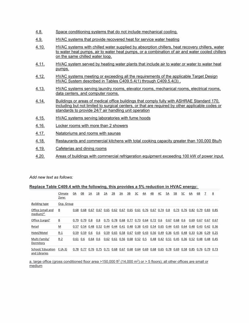
Add new text as follows: Replace Table C409.4 with the following, this provides a 5% reduction in HVAC energy:
Climate Zone:
0A 0B 1A 1B 2A 2B 3A 3B 3C 4A 4B 4C 5A 5B 5C 6A 6B 7 8
Building type Ocp. Group
Office (small and medium)a]
B 0.68 0.68 0.67 0.67 0.65 0.62 0.67 0.65 0.61 0.76 0.67 0.74 0.8 0.73 0.76 0.82 0.79 0.83 0.85
Office (Large)a B 0.79 0.79 0.8 0.8 0.75 0.78 0.68 0.77 0.73 0.64 0.72 0.6 0.67 0.68 0.6 0.69 0.67 0.67 0.67
Retail M 0.57 0.54 0.48 0.52 0.44 0.44 0.41 0.48 0.38 0.43 0.54 0.65 0.44 0.65 0.64 0.48 0.43 0.42 0.36
Hotel/Motel R‐1 0.59 0.59 0.6 0.6 0.59 0.65 0.58 0.67 0.69 0.43 0.56 0.49 0.36 0.45 0.48 0.33 0.36 0.29 0.25
Multi‐Family/ Dormitory
R‐2 0.61 0.6 0.64 0.6 0.62 0.61 0.56 0.68 0.52 0.5 0.48 0.42 0.51 0.45 0.36 0.52 0.48 0.48 0.45
School/ Education and Libraries
E (A‐3) 0.78 0.77 0.76 0.75 0.71 0.68 0.67 0.68 0.64 0.69 0.68 0.65 0.78 0.69 0.58 0.85 0.76 0.79 0.73
a. large office (gross conditioned floor area >150,000 ft2 (14,000 m2) or > 5 floors); all other offices are small or medium

Reason:
The prescriptive path is traditionally the most widely used approach for commercial code compliance in the United States. Though easy to implement, the prescriptive approach does not discriminate between high-performing and poorly performing heating, ventilation, air conditioning (HVAC) system configurations that are both minimally compliant. For example, a high capacity PTAC is less efficient than a packaged rooftop air conditioner, but either one can be used in the prescriptive path. The packaged rooftop unit is a better design choice, both for energy savings and reduced noise in the space. To meet aggressive energy and carbon reduction goals, energy codes will need to transition from prescriptive to performance-based approaches, a transition that has several challenges.
This proposal includes 3 features:
ꞏ An alternative path in Section C403 that can be used optionally for tradeoffs, such as a more efficient system that does not have outside air economizers. This performance path uses minimum efficiency HVAC equipment for all the target systems with a selection of a reasonable and typical system type and related fan and pumping parameters. In this case, mandatory requirements and certain prescriptive requirements are maintained, while most prescriptive requirements can be traded off for improved efficiency in other parts of the system.
ꞏ An addition to the energy credits section (C406) of the code that accounts for the total HVAC system performance, not just heating and cooling efficiency.
ꞏ An optional appendix that can be adopted for stretch codes and utility incentive certification that requires TSPR analysis where it is applicable and requires a higher level of performance, saving 5% vs. minimum efficiency systems.
HVAC System Performance is a discipline performance path and provides a simpler solution to HVAC system evaluation compared to whole building performance, while keeping tradeoffs limited to specific building systems. The Total System Performance Ratio (TSPR) is a metric for evaluation of overall system efficiency instead of individual component efficiency, a solution that could also eventually facilitate the transition to a 100% performance-based code structure. TSPR is a ratio that compares the annual heating and cooling load of a building to the annual energy consumed by the building’s HVAC system.
A web-based calculation tool has been developed for determining a building’s TSPR. Already incorporated into the 2018 Washington State Energy Code, this approach has also been evaluated by the ASHRAE Standard 90.1 Project Committee and has the potential to provide a comprehensive performance-based approach for HVAC system evaluation and analysis
For the stretch code option, implementing a base TSPR minimum requirement for HVAC systems in relevant buildings will result in savings when the least efficient systems allowed under the prescriptive path are required to make some change to improve efficiency in line with a reasonably good prescriptive system. Such changes might include efficiency improvements, better duct design that reduces fan power, or the inclusion of options like economizers, demand controlled ventilation, improvement in energy recovery effectiveness or addition of energy recovery that might be excepted for the particular situation. The HVAC System performance path looks at the performance of all the systems in the building, so smaller systems do not necessarily need to meet higher requirements.
Cost Impact:
The code change proposal will neither increase nor decrease the cost of construction.
For the base proposal, there is no cost impact, as TSPR is an optional path that is not required under the prescriptive path.
For the energy credits addition, this is one of many options, and the energy credits show cost effectiveness through one cost effective path that may not include this option. Adding TSPR to energy credits just increases efficiency.
For the stretch code appendix, there may be a cost increase; however, this option is a jurisdictional adoption choice where the jurisdiction may choose to require improved efficiency performance as a matter of policy, rather than focusing on individual building cost savings, including consideration for environmental externalities and societal costs.
Bibliography: Goel S., R Hart, M Tillou, M Rosenberg, J Gonzalez, K Devaprasad, and J Lerond. 2021. HVAC System Performance for Energy Codes. PNNL-31571. Richland, WA: Pacific Northwest National Laboratory.