hvdc and load modulation for improved dynamic …. lian hvdc...low frequency inter-area oscillations...
TRANSCRIPT

HVDC and Load Modulation for Improved Dynamic Response using Phasor Measurements (GM0073)
Jianming (Jamie) LianPacific Northwest National Laboratory
[email protected] 13-14, 2017Washington, DC
DOE/OE Transmission Reliability Program

Project Overview
• Objective– develop a universal wide-area damping control that
can use a mix of different fast-acting resources to effectively mitigate inter-area oscillations
• Impact:– Manage power grid stability in a much more flexible
manner by utilizing different resources– Improve system damping of inter-area oscillations for
higher power transfer capacity– Enhance robustness of damping controllers to wide-
area communication network effects

Project Team• Pacific Northwest National Laboratory (lead)
– Eric Andersen (PM), Jamie Lian (PI)– Shaobu Wang, Renke Huang– Marcelo Elizondo, Rui Fan, Harold Kirkham– Jacob Hansen, Laurentiu Marinovici, Qian Zhang
• Sadia National Laboratory– David Schoenwald, Felipe Wilches-Bernal
• Arizona State University– Vijay Vittal, Weili Yi
• Penn State University– Minghui Zhu, Hunmin Kim

FY16 Planned ActivitiesTask Deliverables Due Date
1
Develop a decoupled modulation control approach based on wide-area PMU measurements• Decouple different oscillation modes from PMU measurements• Design decoupled damping control using PSS/FACTS devices
8/30/2017
2
Design decoupled damping control for multiple HVDC lines• Perform literature survey on HVDC line/network modeling• Propose test systems with three or more HVDC lines• Extend decoupled modulation control to HVDC lines
8/30/2017
3
Design decoupled damping control for controllable loads• Perform literature survey on controllable load modeling• Design load control strategies for aggregated power modulation• Extend decoupled modulation control to controllable loads
8/30/2017
4 Complete proof-of-concept testing and validation of different control strategies on the WECC system 8/30/2017

WECC System
• WECC has multiple inter-area oscillation modes and suitable for testing proposed damping control technologies
• Major inter-area oscillation modes*:– “N-S” (~0.13 Hz)– “Alberta” (~0.29 Hz)– “BC” (~0.62 Hz)– “Montana” (~0.55 Hz)– “E-W South 1” (~0.53 Hz)– “E-W South 2” (~0.69 Hz)– “E-W middle” (~0.71 Hz)
*D. Trudnowski, “The MinniWECC System Model,” Appendix 2 of J. Undrill and D. Trudnowski, “Oscillation Damping Controls,” Year 1 report of BPA contract 37508, Sep. 2008

Wide-area Damping Control
Area Two
Area OneDamping
Controller
WAMS
Power Grid
+-

Damping ControlHVDC Lines

Area One
Damping Control using HVDC Line
Area One AC Line
HVDC LineRectifier Inverter

HVDC Line ControlRectifier Control
Inverter Control

Minni-WECC Test System
• Pacific DC Intertie (PDCI)– From Celilo converter station at
Dalles, Oregon, to the Sylmar converter station north of Los Angeles, California
• Intermountain Power Project (IPP)– From Intermountain converter
station near Delta, Utah, to the Adelanto Converter Station in Adelanto, California
• TransWest Express Transmission Project (TWE, in operation by 2020)
– From Rawlins, Wyoming, to Las Vegas, Nevada

Case Study
• Three-phase fault occurrs on line 86-87 (AC tie-line)
• Line 86-87 recloses after fault cleared
X

Simulation Results
• Control in each line responds to frequency difference at its terminals

Damping ControlControllable Loads

Area Two
Damping Control using Loads
Area OneAC Line

Load Power Modulation Signal
OFF -> ON
ON -> OFF
Rising Signal
Falling Signal

Load Control Strategy

Device-level Control
• Autonomous response based on local thresholdsON devices OFF devices
Broadcasted rising/falling signals
Local thresholds for turning ON/OFF
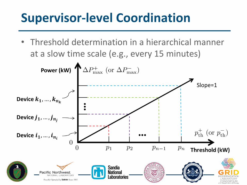
Supervisor-level Coordination
• Threshold determination in a hierarchical manner at a slow time scale (e.g., every 15 minutes)

Simulation Results

Damping ControlDecoupled Modulation

Motivation
• Large-scale power grid usually has multiple inter-area oscillation modes
• Damping controller based on real-time feedback of directly measured signals may not be effective for damping all the oscillation modes
• In the worst case, the damping of two modes could be affected in the opposite directions, which is undesirable

Mode Decomposition
• Solution: Design damping controller based on the real-time feedback of single mode– More effective due to minimum interference among
different oscillation modes
• Existing technique: Band-pass filter– Require a prior knowledge on the frequency– Very difficult to obtain a pure oscillation mode
• Proposed rigorous method for real-time mode decomposition by using remote measurements provided by PMUs

Proposed Method• Offline study of the system property
– Select a chunk of historical data collected by n PMUs– Apply Prony’s analysis to identify modal signals
– Determine the system matrix C that relates identified modal signals to the given PMU measurements
Left-invertible, uniquely determined by system topology and operating point

Proposed Method• Offline study of the system property
– Select a chunk of historical data from n PMUs– Apply Prony’s analysis to determine modal signals– Determine the system matrix C that relates identified
modal signals to the given PMU measurements
• Online mode decomposition– Collect measurements from pre-determined n PMUs– Determine real-time modal signals based on matrix C

Simulation Results on PSS
0 0.1 0.2 0.3 0.4 0.5 0.6 0.7 0.8 0.9
Frequency (Hz)
0
0.5
1
1.5
2
2.5
3
3.5
Am
plitu
de
10-5
Alberta mode
0 0.1 0.2 0.3 0.4 0.5 0.6 0.7 0.8
Frequency (Hz)
0
0.5
1
1.5
2
2.5
3
3.5
Am
plitu
de
10-5
Alberta mode
BC mode
Before Control After Control

FY16 Remaining Activities
• Extend proposed decoupled modulation to HVDC lines and controllable loads
• Connect proposed load control strategy with damping controller
• Perform initial investigation of the impacts of communication delay to control performance
• Submit planned journal and conference papers

PublicationsJournal articles:• S. Wang, R. Fan, R. Huang, J. Lian, R. Diao and Z. Huang, “Enhanced power system damping with
decoupled modulation,” IEEE Transactions on Power Systems, 2017.
• R. Fan, S. Wang, R. Huang, J. Lian, M. Elizondo, “A decoupled HVDC control strategy for power system inter-area oscillation damping,” IEEE Transactions on Smart Grid, 2017.
• M. Elizondo, R. Fan, H. Kirkham, F. Wilches-Bernal, D. Schoenwald and J. Lian “Oscillations damping control using high voltage DC transmission: A review,” IEEE Transactions on Smart Grid, 2017
• H. Kim, M. Zhu and J. Lian, “Distributed robust adaptive frequency regulation of power grid with variable renewable integration,” IEEE Transactions on Automatic Control, 2017.
Conference proceedings:• R. Fan, M. Elizondo, H. Kirkham, F. Wilches, D. Schoenwald and J. Lian “Oscillations Damping Control
Using Multiple High Voltage DC Transmission Lines: Controllability Exploration,” 2018 Transmission and Distribution Conference and Exposition, April, 2018.
• F. Wilches-Bernal, D. Schoenwald, R. Fan, M. Elizondo, and H. Kirkham, “Analysis of the impact of network-induced latencies in feedback signals on HVDC damping controllers,” 2018 Transmission and Distribution Conference and Exposition, April, 2018.
• J. Lian, Q. Zhang, L. Marinovici, R. Fan, R. Huang and J. Hansen, “Hierarchical decentralized load control strategy for inter-area oscillation mitigation” 2018 Transmission and Distribution Conference and Exposition, April, 2018.

FY17 Proposed Activities
• Investigate the impacts of communication effects (delay, packet loss, etc.) to control performance
• Study the interactions among damping control realized by HVDC lines, controllable loads, PSS through integrated testing
• Validate damping control strategies on the full WECC system model using commercial tools
• Improve the resilience of wide-area monitoring and control systems to cyber-physical attacks


HVDC Expansion Plans
Several lines could be potential candidates to participate in damping modulation because of their alignment with typical oscillations modes in the WECC.
31
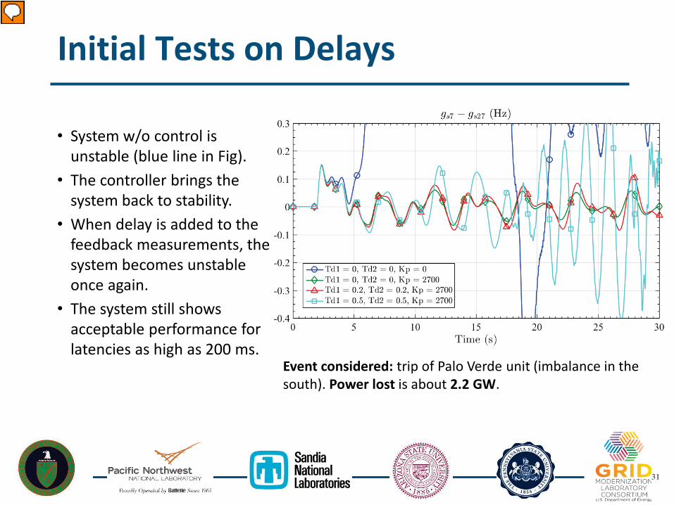
Initial Tests on Delays
• System w/o control is unstable (blue line in Fig).
• The controller brings the system back to stability.
• When delay is added to the feedback measurements, the system becomes unstable once again.
• The system still shows acceptable performance for latencies as high as 200 ms.
Event considered: trip of Palo Verde unit (imbalance in the south). Power lost is about 2.2 GW.