hv_lect8
DESCRIPTION
high voltage lectureTRANSCRIPT

High voltage Engineering
Lecture No. 8High Voltage Generation

Lecture contents
• Impulse voltage generation

Transient/Impulse voltage
• Studies of transient disturbances on a transmission system have shown that lightning strokes and switching operations are followed by a traveling wave of a steep wave front
• When a voltage wave of this type reaches a power transformer it causes an unequal stress distribution along its windings and may lead to breakdown of the insulation system
• It has, therefore, become necessary to study the insulation behavior under impulse voltages

• An impulse voltage is a unidirectional voltage which rises rapidly to a maximum value and then decays slowly to zero
• The wave shape is generally defined in terms of the times t1 and t2 in microseconds, where t1 is the time taken by the voltage wave to reach its peak value and t2 is the total time from the start of wave to the instant when it has declined to one-half of the peak value
• The wave is then referred to as a t1/t2 wave

• The exact method of defining an impulse voltage, however, is specified by various International Standards
• The British Standard specification defines the impulse voltage in terms of nominal wave front and wave tail durations
• Fig 4.5 shows the Shape of an impulse wave where the nominal wave front duration t1 is specified as


• t1 = 1.25 T1T2
• Where
• OT1 = time for the voltage wave to reach 10% of the peak voltage.
• OT2 = time for the voltage wave to reach 90% of the peak voltage.
• The point O1 where the line CD cuts the time axis is defined as the nominal starting-point of the wave
• The nominal wave tail t2 is the time between O1 and the point on the wave tail where the voltage is one-half the peak value, i.e. t2 = OIT4.

• The wave is then referred to as a t1/ t2 wave and according to the standard specified in B.S. 923 a 1/50 μsec wave is the standard wave
• The specification permits a tolerance of up to ±50% on the duration of the wave front and ±20 % on the duration of the wave tail
• In the corresponding American specification, the nominal wave front duration is defined as given by 1.5T1T2 and the standard wave is a 1.5/40 μsec
• The tolerances allowed on the wave front and the wave tail are ±0.5 μsec and ±10 μsec respectively

Single Stage Impulse Generator
• An impulse generator essentially consists of a capacitor which is charged to the required voltage and discharged through a circuit the constants of which can be adjusted to give an impulse voltage of desired shape.
• The basic circuit of a single-stage impulse generator is shown in Fig. 5(a) where the capacitor C1 is charged from a direct current source until the spark-gap G breaks down
• A voltage is then impressed upon the object under test of capacitance C2.

Single stage impulse generator

• a) Single-stage Impulse Generator Circuit
• The wave-shaping resistors R1 and R2 control respectively the front and the tail of the impulse voltage available across C2. An analysis of the simple circuit is given as follows.
• Figure 4.6 (b) represents the Laplace transform circuit of the impulse generator of Fig. 4.6 (a) and the output voltage is given by the expression:


14
a) Single-stage Impulse Generator Circuit
By Substitution:
2. Transient / Impulse Voltage

15
a) Single-stage Impulse Generator Circuit
Transient Voltage

16
a) Single-stage Impulse Generator Circuit
Where S1 and S2 are the roots of the equation s2+as+b = 0 and both will be negative. From the transform tables
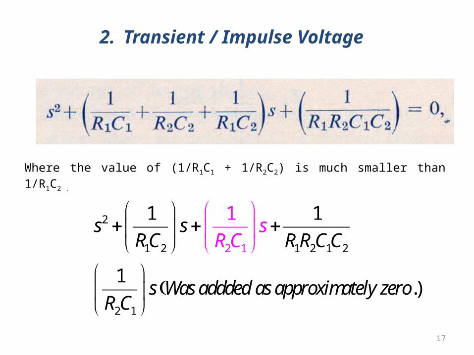
In a practical case R2 is much greater than R1 and C1 much greater than C2 and an approximate solution is obtained by examining the auxiliary equation:
2. Transient / Impulse Voltage
17
Where the value of (1/R1C1 + 1/R2C2) is much smaller than 1/R1C2 .
2
1 2 1 2 1 2
2 1
2 1
1 1
1
1
.)
s sRC R R C C
s Was addded as approximately zeroR
sC
C
R
2. Transient / Impulse Voltage

18
a) Single-stage Impulse Generator Circuit
and the graph of the expression is shown in Fig. 6.
2. Transient / Impulse Voltage
Fig: 6

19
a) Single-stage Impulse Generator Circuit
2. Transient / Impulse Voltage

20
a) Single-stage Impulse Generator Circuit
The above analysis shows that the wave shape depends upon the values of the generator and the load capacitances and the wave-control resistancesThe exact wave shape will be affected by the inductance in the circuit and the stray capacitancesThe inductance depends upon the physical dimensions of the circuit and is kept as small as possible.
2. Transient / Impulse Voltage

21
a) Single-stage Impulse Generator Circuit
The simplified circuit is shown in Fig. 7(a) where C1 = discharge capacitance of generator C2 = capacitance of the load, L1 = internal inductance of generator, L2 = external inductance of load and connections, R1 = resistance controlling the wave front, R2 or R = resistance controlling the wave tail
2. Transient / Impulse Voltage

22
a) Single-stage Impulse Generator Circuit
The wave-tail resistance can be either on the load side or on the generator side
Tail of the impulse wave is generally long compared with its front-as is in the case of a standard wave voltage of 1/50 or 1.5/40 μsec very little error results from ignoring the wave-tail resistance in the calculation of the wave front duration
The circuit, therefore, can be further simplified to the form shown in Fig. 7(b).
2. Transient / Impulse Voltage

23
a) Single-stage Impulse Generator Circuit
2. Transient / Impulse Voltage
Fig: 7:

24
b) Multistage Impulse Generator Circuit The one-stage circuit is not suitable for higher voltages because of the difficulties in obtaining high direct current voltagesIn order to overcome these difficulties, Marx suggested an arrangement where a number of condensers are charged in parallel through resistances and discharged in series through spark gapsA typical circuit is presented in Fig.8 which shows the connections for a five-stage generatorThe stage capacitors C are charged in parallel through high-value charging resistors R. At the end of the charging period, the points A, B,……E will be at the potential of the d.c. source,
2. Transient / Impulse Voltage

25
b) Multistage Impulse Generator Circuit
2. Transient / Impulse Voltage
Fig: 8

26
b) Multistage Impulse Generator Circuit
e.g. + V with respect to earth, and the points F, G,……, M will remain at the earth potential The discharge of the generator is initialized by the breakdown of the spark gap AF which is followed by simultaneous breakdown of all the remaining gapsWhen the gap AF breaks down, the potential on the point A changes from + V to zero and that on point G swings from zero to -V owing to the charge on the condenser A.GIf for the time being the stray capacitance C is neglected, the potential on B remains + V during the interval the gap AF sparks over.
2. Transient / Impulse Voltage

27
b) Multistage Impulse Generator Circuit
A voltage 2V, therefore, appears across the gap BG which immediately leads to its breakdownThis break down creates a potential difference of 3V across CH; the breakdown process, therefore, continues and finally the potential on M attains a value of - 5VIn effect, the low voltage plates of the stage capacitors are successively raised to - V, - 2V, ……. - nV, if there are n stagesThis arrangement gives an output with polarity opposite to that of the charging voltage.
2. Transient / Impulse Voltage

28
b) Multistage Impulse Generator Circuit The above considerations suggest that a multistage impulse generator should operate consistently irrespective of the number of stagesIn practice for a consistent operation it is essential to set the first gap (G1) for breakdown only slightly below the second gap (G2)A more complete analysis shows that the voltage distribution across the second and higher gaps immediately after the breakdown of the lowest gap (G1) is governed by the stray capacitances and gap capacitances shown in dotted lines in Fig.4.11. The effect of stray capacitances on voltage across G2 immediately after breakdown of G1 may be estimated as follows:
2. Transient / Impulse Voltage

29
b) Multistage Impulse Generator Circuit
Assume the resistors as open circuits and the stray capaci tances negligible in comparison with the stage capacitors. Let (A) in Fig.8 be charged to + V
After breakdown of G1 the point G initially at earth will assume a potential - V, but the potential of B is fixed by the relative magnitudes of C1, C2 and C3 and is given by
2. Transient / Impulse Voltage


31
b) Multistage Impulse Generator Circuit If C2 = 0, VG2 reaches its maximum value of 2V. If both C1 and Cs are zero, V G. will equal to V, i.e. its minimum value
It is apparent, therefore, that the most favorable conditions for the operation of the generator occur when the gap capacitance C2 is small and the stray capacitances C1 and C3 are large
The conditions set by the above expression are transient, as the stray capacitors start discharging
The practical stray capacitors are of low values, consequently the time constants are relatively short 0.1 micro second or less
2. Transient / Impulse Voltage

32
b) Multistage Impulse Generator Circuit
For consistent breakdown of all gaps the axes of the gaps should be in one vertical plane so that the ultraviolet illumination from the spark in the first gap irradiates the other gapsThis ensures a supply of electrons in the gaps to initiate break down during the short period when the gaps are subjected to the over-voltageThe consistency in the firing of the first stage spark gap is improved by providing illumination from ultraviolet lamps placed below the first gap
2. Transient / Impulse Voltage

33
b) Multistage Impulse Generator Circuit
The wave-front control resistors, in a multistage generator, can be connected either externally to the generator or distributed within the generator, or partly in and partly outside itIn the best arrangement, about half of the resistance is outside the generatorAn advantage of distributing the wave-front resistors within the generator is that it reduces the need for an external resistor capable of withstanding the full impulse voltage.
2. Transient / Impulse Voltage

34
b) Multistage Impulse Generator Circuit
If all the series resistances are distributed within the generator, the inductance and capacitance of the external leads and the load form an oscillatory circuitAn external resistance, therefore, becomes necessary to damp out these oscillationsThe method of placing part of the wave-front control resistance in series with each gap serves to protect against disruptive discharge as well as to damp out any generator internal oscillationWave-tail control resistances are generally used as the charging resistors within the generator
2. Transient / Impulse Voltage

35
b) Multistage Impulse Generator Circuit
2. Transient / Impulse Voltage
Fig: 9.

36
b) Multistage Impulse Generator Circuit
The circuit shown in Fig.9 is commonly used to obtain high efficiency with distributed series resistors.
The value of R3 is made large compared with R1 and R2 is made as small as is necessary to obtain the required length of the wave tail.
In a practical generator employing this circuit, the voltage drop in R1 was made less than 1% of the output voltage by selecting suitable values of the parameters
The stage capacitance was 0.2 μF, R1 was about 40Ω and the wave-tail resistance R2 required for a 5 μ sec wave tail was about 25Ω. R3 was made nearly 10kΩ
2. Transient / Impulse Voltage

37
b) Multistage Impulse Generator Circuit
Impulse generators are characterized by the total nominal voltage, the number of stages and the stored energy
The nominal output voltage is given by the product of the highest charging voltage and the number of stages
Because of the resistance and inductance in series with the generator and the test circuits, the voltage across the test object is lower than the nominal output of the generator
The nominal energy of the generator is defined as ½ CgV2 , where Cg denotes the discharge capacitance of the generator and V the maximum nominal voltage.
2. Transient / Impulse Voltage

38
b) Multistage Impulse Generator Circuit The energy required varies over a wide range depending upon the nature of the object under test.
For example, the energy of the generator can be low for testing insulator strings, isolators, etc., whereas when tests are carried out on objects of low impedance such as transformers, the energy must be higher
2. Transient / Impulse Voltage

Conclusive formulae for wave front and tail for impulse generator problems


Next Lecture
• Generation of High voltage– Problem discussion