hvo/rvts-1: a prototype remote video telemetry system … · remote video telemetry system for...
TRANSCRIPT

DEPARTMENT OF THE INTERIOR
U.S. GEOLOGICAL SURVEY
HVO/RVTS-1: A PROTOTYPEREMOTE VIDEO TELEMETRY SYSTEM FOR MONITORING THE
KILAUEA EAST RIFT ZONE ERUPTION, 1997
Carl R. Thornber1
Open-File Report
OF 97-537
This report is preliminary and has not been reviewed for conformity with the U.S. Geological Survey editorial standards (or with the North American Stratigraphic Code). Any use of trade, product, or firm names is for descriptive purposes only and does not imply endorsement by the U.S. Government.
'Hawaiian Volcano Observatory, U.S. Geological Survey, P.O. Box 51, Hawaii Volcanoes National Park, Hawaii 96718

Thornber, C.R. USGS OF_97-537
TABLE OF CONTENTS
General Overview of the System 3
The Video Telemetry Array 3
The Remote Transmission Site ,. 4The Remote Transmitter Hub 5The Remote Camera Sites 7
The Repeater Site 8
The Receiver site 9Deployment Tactics and Results: April-September 1997 10
Remote Transmitter Site A (May 5 - August 12,1997) 12Remote Transmitter Site B (May 12 - August 22,1997) 11Remote Transmitter Site C (August 22 - September 30,1997) 13
Conclusion and Recommendations 13
References 18 Acknowledgments 18
LIST OF FIGURESFigure 1. The Video Telemetry array 4Figure 2. Transmitter Site Equipment Setup 6
a) Transmitter Hubb) Transmitter Instrument Package
Figure 3. Camera sites at Pu'u 'O'o 11 Figure 4. Remote Camera site A2 and sample images 14 FigureS. Remote Camera site Bl and sample images 15 Figured. Remote Camera site B2 & B3 and sample images 16 Figure 7. Remote Camera site C2&C3 and sample images 17
LIST OF TABLESTable 1. Equipment deployed at remote transmitter hub 5 Table 2. Equipment deployed at remote camera sites 8 Table 3. Equipment deployed at repeater site 9 Table 4. Receiver hub equipment at HVO 9 Table 5. Summary of remote camera deployment from April - September 1997 11

Thornber, C.R. USGS OF_97-537
General Overview of the System
HVO/RVTS-1, a prototype Remote Video Telemetry System, is currently in use at the U.S. Geological Survey's Hawaiian Volcano Observatory (HVO). Recording of video images transmitted at near real-time from the currently active Puv u V ON O vent on the east rift zone of Kilauea Volcano, began in early April 1997. Since that time, the RVTS-1 has proven its value and reliability as an eruption monitoring device and promises to be a long-lived addition to HVO's real-time instrumental array.
The system comprises a unique configuration of mostly "off-the-shelf products. The key components are a HyperScan digital transmitter module and a desktop computer with HyperScan receiver software (Sensormatic, Inc.). The high-speed broad-band radio communication link is achieved using FreeWave Wireless Data Transceivers (FreeWave Technologies, Inc.). The receiver software package allows for near-real-time, high-resolution image display along with storage and review of digital images in a moving picture mode.
This report provides a technical overview of the first remote video telemetry system of its type. The HVO-RVTS-1 is significantly more advanced than slow-scan video telemetry developed by USGS for monitoring Mount St. Helens in 1987 (Furakawa, et al. 1992). Also, this system provides a more robust, portable and low-cost alternative to the closed-circuit, microwave TV system that was successfully used by the USGS at Mount St. Helens in 1980 (Miller and Hoblitt, 1981). There is sufficient information provided herein to reproduce the new system. Detailed instructions on the installation and operation of system components is beyond the scope of this report and the reader is referred to well-written equipment manuals supplied by respective manufacturers. A brief summary of recorded eruptive activity from April through September 1997 is presented to demonstrate the utility and value of the system as an eruption monitoring tool. Finally, suggestions are made for improvements which could lend greater versatility to this prototype system for live volcano monitoring.
The Video Telemetry ArrayVideo signals from up to four cameras at the eruption site are transmitted from the
middle east rift zone of Kilauea to a repeater at 6700-ft elevation on southeast flank of Mauna Loa. The signals are relayed to a receiver at HVO, on the west edge of Kilauea's summit caldera. (fig. 1). Radio modems at transmitter, repeater and receiver sites are FreeWave Wireless Data Transceivers. FreeWave radio transmissions are broadcast in a modulated "frequency hopping" style over a "spread spectrum" ISM band at 902-928 MHz and do not presently require an FCC license. This style of radio transmission is restricted to line-of-sight deployment with a maximum range of 60 km. In the HVO/RVTS-1 array, a high elevation in line repeater is needed because line-of-sight transmission is obscured by high terrain between transmitter and receiver locations.
_ TTUfFor the purpose of programming transmission/reception parameters, the FreeWave
Transceivers are uniquely identified by call numbers (unit serial numbers) and assigned as "Master", "Repeater" and "Slave"2 modems hi a "point-to-point" array. In order to avoid interference with other FreeWave arrays, a single and unique frequency-hopping interval is programmed into all three in-line Transceivers. The RVTS array has all in-line modems
2 Terminology used by FreeWave Technologies is presented in quotations

Thornber, C.R. USGS OF_97-537
configured with a 19,200-baud data transmission rate, which is compatible with the computer communication port at the receiver hub and sufficient for continuous image transmission.
The ~34-km-long link between transmitter and repeater is accomplished using a 6 element directional Yagi antenna (896-960 MHz, 12 dB gain). The Mauna Loa repeater and HVO receiver modems, which are -16 km apart, each use a 33-inch omnidirectional whip antennae (896-940 MHz, 5 dB gain).
A precise discussion of similar telemetry system capabilities and equipment options is provided on the Internet website of the University NAVSTAR Consortium (UNAVCO) for GPS research (http://www.unvavco.ucal.eduX Details of HVO/RVTS-1 telemetry equipment specifications and installation instructions are provided by the FreeWave manual and information can be obtained at the FreeWave Internet Website (http//www.freewave.corrO.
Fiaure 1. The Video Telemetrv Arrav
The Remote Transmission SiteHVO/RSVT-1 is transmitting video images from the hazardous and corrosive environs
of the Pu'u 'O'o eruptive vent. All electrical instruments, including cameras, are contained within heavy-duty enclosures designed for moisture- and acid-free operating conditions. Pelican cases and U.S. Army surplus ammunition boxes are sealed with well-greased gaskets and silicone adhesive around connection ports. When routinely packed with fresh desiccant and acid absorbers, these cases have proven to be sufficiently leak-proof and corrosion-resistant for their contents to remain unscathed amid the extreme near-vent volcanic and atmospheric conditions. Camera sites are linked to a transmitter hub by as long as 100 m coaxial (75 ohm) or fiber optic cables. This configuration provides for multiple viewing

Thornber, C.R. USGS OF_97-537
angles both within and around the cone and allows for relatively safe placement of the transmitter instrument package.
The Remote Transmitter HubThe transmitter hub setup is illustrated in figure 2a and equipment specifications are
summarized in table 1. A weather-resistant fiberglass chest contains four interconnected 12 volt batteries, an encased charge regulator and a transmitter instrument package. The separately encased package of instruments contains a fiber optic receiver, a Hyperscan transmitter, an alarm timer, and a FreeWave transceiver (fig. 2b). The directional (Yagi) antenna is mounted on an 8-foot-high antenna pole near the transmitter hub and connected to the transceiver via a 30-ft coaxial cable especially configured with reverse male SMA connectors and supplied by FreeWave Technologies;-Inc. A 200 watt solar panel array maintains the regulated recharge of four 12V, 85 amp-hour deep-cycle batteries. The batteries supply power for the transmitter instruments as well as cameras proximal to the hub. The total current drawn by the transmitter instrument package is less than 0.6 amp With an additional current load of up to 0.5 amps from near-hub camera stations, the system can be sustained for two weeks without sunshine and still avoid irrecoverable battery degradation. Camera sites that draw more than 0.5 amps are equipped with a separate 50 to 150 watt solar power array and up to three 85amp-hour, interconnected, deep cycle 12V batteries.
Table 1. EQUIPMENT DEPLOYED AT REMOTE TRANSMITTER HUBComponentFiber Optic Receiver
Video Transmitter
Alarm Timer
Radio Modem
AntennaAntenna Cable
Solar Array
Charge Regulator
Batteries
Model #FXR010
HyperScanTX50H
"Camera Event Timer"
FreeWave DGR-115H
EAN0900YA
ASM0030CA
ASC 12/16
DescriptionConverts Pulse Frequency Modulated optical signal into composite analog video signalDigital Transmitter Module converts analog camera video signal inputs into digital signals, processes and encodes image compression files output to the radio modem
Signals a Hyperscan "alarm" condition for recording images at specified time intervalsUS kbaud Wireless Data Transceiver in weather resistant enclosure
6 element Yagi directional antenna
Specifications12VDC
12VDC
12VDC
12VDC896-960MHZ
140mA
250mA
30mA
180mA
12dB
30-foot coaxial cable with reverse male SMA and male N-type connectors
Corrosion resistant, ~4by 6-ft. solar panels with heavy duty alluminum alloy frames and weatherproof Junction boxesSolid state battery charge regulator for photovoltaic enerev systems4, heavy-duty, deep-cycle batteries
200 watt
12VDC
12VDC
16A
85 amp-hour
SourcePolaris Industries
Sensormatic Inc., Video Products Division
FB Engineering, Hilo, HI
FreeWave Technologies, Inc.
FreeWave Technologies, Inc.
FreeWave Technologies, Inc.
Local Source
Specialty Concepts, Inc.
Local Source

Thornber, C.R. USGS OF_97-537
Figure 2. Transmitter Site Equipment Setup at Pu'u 'O'o
2a) Transmitter Hub (September 11, 1997): 1) Transmitter Hub Container: an environment-proof fiberglass box with hinged lid housing four 12V deep cycle batteries (in base) and a charge regular and transmitter instrument package in separate sealed cases;2) Solar Panel Array: 200 watt, wired to charge regulator in the transmitter hub container.3) 6 Element Directional Yagi Antenna with 896-960MHz transmission band and 12db elevated feed gain, connected to the FreeWave data transceiver in the transmitter hub container; 4) Remote Camera Site (C3)
2b) Transmitter Instrument Package (September 11, 1997): 1) HyperScan TX50H Digital Transmitter Module: 2) Camera Event Timer (FB Engineering); 3) FreeWave DGR-115H 1 ISkbaud Wireless Data Transceiver 4) Battery Charge Regulator (24V, 16amp) connecting the Solar Array to the four 12V battery bank and with a terminal strip for 12V power lines to all transmitter hub devices. 5) Dessicants and Acid Absorbers contained in air-permeable bags are placed in all sealed equipment boxes to further prevent equipment deterioration in noxious environmental conditions

Thornber, C.R. USGS OF_97-537
The HyperScan TX50H Digital Transmitter Module converts the analog camera video signal inputs from up to four on-site cameras into digital signals. The digital video image data from each camera is stored in memory, along with date, time and alarm information. Stored digital images are processed by a proprietary image compression routine (HyperScan ) and sent via RS232 output to the radio transceiver module. Primary HyperScan image files, referred to as "training images," are sent in their entirety. In subsequent images, called "delta images," only changes in training image files are sent, thus enhancing efficiency of transmission. The desired frequency of training image collection and processing is programmable from the receiver hub using HyperScan RX-50S software and is set at 5-minute intervals in the current system. Additional details on HyperScan
Timequipment can be obtained by consulting the HyperScan system operating and instruction manuals and general product specifications are posted by Sensormatic Inc., Video Products Division on the Internet at http://www.sensormatic-vdD.com.
The FB Engineering "Camera Event Timer" sends a timed electronic pulse to the HyperScan Digital Transmitter Module. The transmitter responds to this pulse by signaling the receiver hub to save a series of incoming images. This image-recording condition is
Tmireferred to by HyperScan as an "alarm condition". The timing device has a 10 position DIP switch that can be configured to trigger alarm conditions every 1 minute for up to 9 minutes or at 10 minute intervals for up to 90 minutes. A 5-minute alarm trigger interval is used by the current system, thus enabling the receiver hub to save several images from each camera every 5 minutes.
The Remote Camera SitesEquipment specifications for HVO/RVTS-1 Remote Camera Sites are summarized in table 2. Three very different types of video cameras have undergone trial-by-fire at the current eruptive vent. The three types comprise 1) a "desktop computer style" communication camera (Canon VC-C1 MKII); 2) Two "surveillance type" compact CCD cameras (Polaris Industries VT80 and Cohu Electronics Series 2222) and 3) a stripped-down "professional video camera" (Panasonic WV 200CLE, donated by Kaxlo Productions). Specific information on these and two other cameras presently available for use is provided in table 2.
The Polaris VT80C and Cohu 2222 security cameras both suffered non-warranty damage under adverse field conditions. The Panasonic "TV camera" images are hampered by inaccurate auto white balance corrections and by the restricted auto iris range set by an optimal day/night filter. Among the cameras tried, the Canon VCC1 MKII is recommended for durability, simplicity and image quality. This unit also has built-in capabilities for remote control of Pan-Tilt-Zoom (PTZ). The possibilities for configuring PTZ control via a simple radio communication link are being explored.
The transmission of video between remote cameras and the communication hub at Puxu x Ox o is accomplished in two ways. Most camera sites have been placed at the end of 50 to 75 m of heavily insulated coaxial cable. For longer distances a fiber optic connection is desirable. A fiber optic cord is less prone to environmental deterioration than coaxial cable ' and it will not attract lightning. A -100 m-long fiber optic connection has been used at two remote camera sites. The fiber optic line requires a powered signal converter at each end and may necessitate deployment of a camera-site power station. The signal converter at the camera end (fiber optic transmitter) converts the analog video signal from the camera into a pulse frequency modulated signal for optical transmission. This process is reversed by the
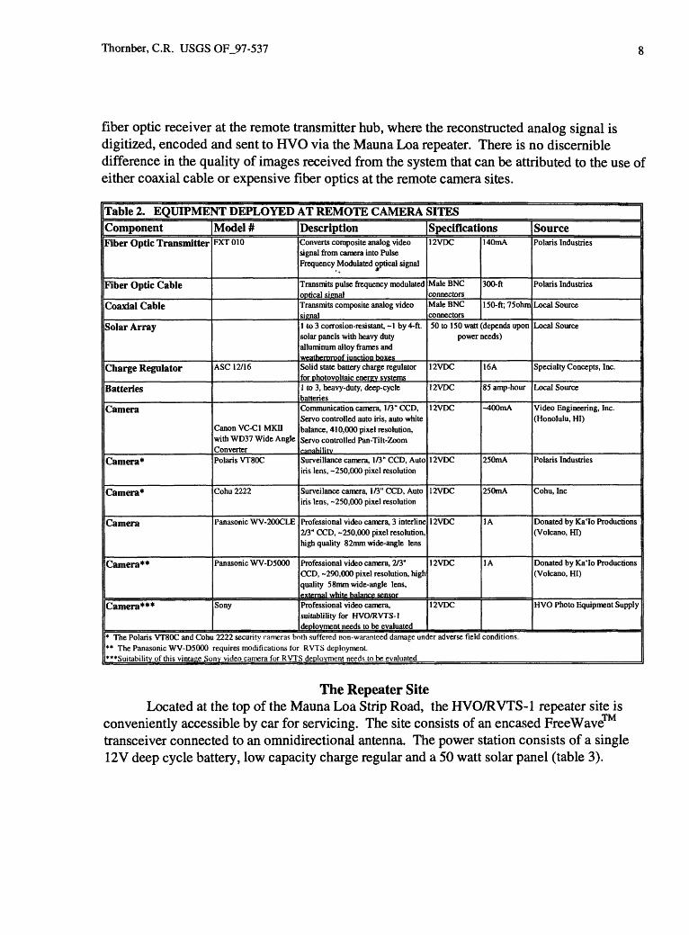
Thornber, C.R. USGS OF_97-537
fiber optic receiver at the remote transmitter hub, where the reconstructed analog signal is digitized, encoded and sent to HVO via the Mauna Loa repeater. There is no discernible difference in the quality of images received from the system that can be attributed to the use of either coaxial cable or expensive fiber optics at the remote camera sites.
Table 2. EQUIPMENT DEPLOYED AT REMOTE CAMERA SITESComponent | Model # (Description (SpecificationsFiber Optic Transmitter
Fiber Optic Cable
Coaxial Cable
Solar Array
Charge Regulator
Batteries
Camera
Camera*
Camera*
Camera
Camera**
Camera***
FXT010
ASC 12/16
Canon VC-C1 MKH with WD37 Wide Angle ConverterPolaris VT80C
Cohu 2222
Panasonic WV-200CLE
Panasonic WV-D5000
Sony
Converts composite analog video signal from camera into Pulse Frequency Modulated optical signal
Transmits pulse frequency modulated optical signalTransmits composite analog video signal1 to 3 corrosion-resistant, -1 by 4-ft. solar panels with heavy duty alluminum alloy frames and weatheroroof junction boxesSolid state battery charge regulator for photovoltaic energy systems1 to 3, heavy-duty, deep-cycle batteriesCommunication camera, 1/3" CCD, Servo controlled auto iris, auto white balance, 410,000 pixel resolution, Servo controlled Pan-Tilt-Zoom canabilitvSurveillance camera, 1/3" CCD, Auto iris lens, -250,000 pixel resolution
Surveilance camera, 1/3" CCD, Auto iris lens, -250,000 pixel resolution
Professional video camera, 3 interline 2/3" CCD, -250,000 pixel resolution, high quality 82mm wide-angle lens
Professional video camera, 2/3" CCD, -290,000 pixel resolution, high quality 5 8mm wide-angle lens, external white balance sensorProfessional video camera, suitablility for HVO/RVTS-1 deployment needs to be evaluated
12VDC
Male BNC connectorsMale BNC connectors
140mA
300-ft
150-ft;75ohm
50 to 150 watt (depends upon power needs)
12VDC
12VDC
12VDC
12VDC
12VDC
12VDC
12VDC
12VDC
16A
85 amp-hour
-400mA
250mA
250mA
1A
1A
SourcePolaris Industries
Polaris Industries
Local Source
Local Source
Specialty Concepts, Inc.
Local Source
Video Engineering, Inc. (Honolulu, HI)
Polaris Industries
Cohu, Inc
Donated by Ka'Io Productions (Volcano, HI)
Donated by Ka'Io Productions (Volcano, HI)
HVO Photo Equipment Supply
* The Polaris VT80C and Cohu 2222 security cameras both suffered non-waranteed damage under adverse field conditions. ** The Panasonic WV-D5000 requires modifications for RVTS deployment. ***Suitabilitv of this vintace Sonv video camera for RVTS deployment needs to be evaluated
The Repeater SiteLocated at the top of the Mauna Loa Strip Road, the HVO/RVTS-1 repeater site is
conveniently accessible by car for servicing. The site consists of an encased FreeWave transceiver connected to an omnidirectional antenna. The power station consists of a single 12V deep cycle battery, low capacity charge regular and a 50 watt solar panel (table 3).

Thornber, C.R. USGS OF_97-537
Table 3. EQUIPMENT DEPLOYED AT REPEATER SITEComponentRadio Modem
AntennaAntenna Cable
Solar Array
Charge Regulator
Battery
Model #FreeWaveDGR-115H
EAN0905WB
ASM0030CA
ASC 12/16
Description115 kbaud wireless data transceiver in weather resistant enclosure33" ominidirectional antennae
Specifications12VDC
896-960MHz
180mA
5dB
30-foot coaxial cable with reverse male SMA and male N-type connectors
1 corrosion-resistant, -1 x 4-ft. solar panel with heavy duty alluminum alloy frames and weatherproof junction boxesSolid state battery charge regulator for photovoltaic enercv systems1, heavy-duty, deep-cycle battery
50 watt
12VDC
12VDC
16A
85 amp-hour
SourceFree Wave Technologies, Inc.
Free Wave Technologies, Inc.
FreeWave Technologies, Inc.
Local Source
Specialty Concepts, Inc.
Local Source
The Receiver SiteA summary of equipment used at the HVO Receiver Site, along with general
specifications, is presented in table 4. This site is the communication hub for the HVO/RVTS-1 . An omnidierectional antenna mounted outdoors at HVO serves a FreeWave transceiver that is connected to a COM port of the receiver hub computer. A standard terminal emulator program on this computer is used to configure all in-line radio modems . A licensed HyperScan RX50S software package is used to communicate through the telemetry array with the remote site HyperScan TH50RX Digital Transmitter Module. The software is user friendly with mouse controlled pull-down menus and simple "point and click" access to all functions. The receiver software controls the reception, display, archiving and reviewing of digital images from the remote site. Options for labeling and time/date stamping of transmitted images are also controlled at the receiver hub. The computer is fitted with a serial-number-encoded HyperScan software key that is required for complete program operation. For a complete overview of software utilities, optional configurations, and detailed instructions for installation and operation, the reader is referred to
TTlyfthe well-written equipment manual provided by HyperScan .
Table 4. RECEIVER HUB EQUIPMENT AT HVOComponentRadio Modem
AntennaAntenna Cable
Desktop Computer
Receiver Software *
Model #FreeWave DGR-115H
EAN0905WBASM0050CA
Micron- Millenia Pro Plus (Upgraded)
Hyperscan RX50S Version 2.1
Description115 kbaud wireless data transceiver in weather resistant enclosure33" ominidirectional antennae
Specifications12VDC
896-960MHz
180mA
5dB50-foot coaxial cable with reverse male SMA and male N-type
connectors200MHz Pentium Processor, 64MB RAM, SVGA 4MB Video
Adaptor, 2 GB and 9 GB ultra SCSI hard drives, Microsoft NT 4.0 ooeratinfi svstem 17" hieh-res color monitor
Configures Hyperscan communication link, uncompresses and displays HyperScan image files from the TX50H Transmitter, includes options for saving, manageing and reviewing image Hafahases. and for remote camera control and user security.
SourceFreeWave Technologies, Inc.
FreeWave Technologies, Inc.FreeWave Technologies, Inc.
Micron Electronics, Inc
Sensormatic Inc., Video Products Division
||*A software key is required in Iptl printer port to operate the HyperScan software (except image review and "demo" modes)
The communication link to the radio modem at the receiver site is handled by HyperScan as a null modem single-line link. Digital images transmitted and displayedand/or archived by HyperScan can be set for high, normal or low resolution. High resolution images are used for all remote camera sites and are transmitted at a rate of less than 4 seconds per frame. Incoming images can be viewed on the receiver hub monitor in multi- frame-/single-camera (time-lapsed mode), multi-frame/multi-camera, or single-frame/single- camera modes with either full screen or screen-plus-menu viewing options.

Thornber, C.R. USGS OF_97-537 10
The system is set to store all "alarmed" images (described above) from each camera as transmitted over ~30 seconds at 5 minute intervals. The option exists to save every incoming image in the same time-coded image file as the "alarmed" images. The image review software allows playback of time coded image files in a moving picture mode with options for date and time selection, moving picture dwell-time, reverse playback, frame freezing and image capture to a clipboard file.
HVO/RVTS-1 experienced a HyperScan software upgrade from version 2.0 to version 2.1 in July 1997. The most significant change in software is a less restrictive proprietary format for image storage and review (v. 2.0 RDX file format changed to v. 2.1 DBF file format). The new image review program can be loaded on independent computer workstations (without a software key), allowing for convenient off-site image review and processing. The newer software is supplied with a database conversion utility that is only marginally effective at successful conversion of large HyperScan RDX image files to DBF formats. For this reason, and in order to view images collected from April through July 1997, the earlier version (v. 2.0) is preserved in a separate directory on the receiver hub computer.
Image files are stored in directories that are changed weekly in order to keep HyperScan image files archived in easily manageable sizes of less than 200 Mb. Establishing a new storage directory is a non-intuitive process not described in the instruction manual. A set of blank proprietary format files (files with suffixes of ".dbf', ".cdx", ".fil" and ".tre" in the HyperScan RX directory) are copied to a new directory on the storage drive and renamed with date-name prefixes. Before loading the new "date.dbf' file into the HyperScan software as a new "system default" database, the data transmission link must be interrupted. After the new default condition is set and the communication link is reestablished, the program will begin writing saved image files to the new database file. HyperScan image files are presently stored on a 9 GB hard drive partitioned into 2 GB sectors and thus accessible by LAN-linked DOS-or NT-based workstations for image review. Until a dedicated removable-media storage device is implemented, the files are backed-up via LAN-line to a high-capacity multi-user tape backup system at HVO.
The receiver hub computer is conveniently located where well-trained HVO staff are able to view the eruption conditions at a glance or complete a review of images in the active
__ TX/Iimage directory. This multi-user environment is supported by the HyperScan software security package (password protected) which is invoked to prevent inadvertent access to system configuration and database maintenance privileges.
HVO/RVTS-1 Deployment Tactics and Results: April-September 1997Three different camera configurations of two and three cameras have been positioned
near the rim of PuN u N CTo crater, viewing activity within and around the cone from April through September 1997. These sites and respective camera views are illustrated in figure 3. Two separate remote transmitter sites (sites A and C) were stationed on the north rim of Puv u N CTo with views into the crater. An interim site on the south rim of the cone (site B) was used to monitor Episode 55 South Shield activity as well as that within the Puv u N CTo crater. Site C was established when eruptive conditions threatened site B. A summary of Remote Camera equipment configurations and deployment intervals for each site is presented in table 5.

Thornber, C.R. USGS OF_97-537 11
Figure 3. Camera Sites at Pu' u ' O* o
September 11,1997 (Photo by J. Kauahikaua)
Table 5. Summary of remote camera deployment from April - September 1997
Begin Date
4/12/97
4/12/975/7/97
5/12/97
5/15/97
7/1/97
7/1/97
8/22/97
8/22/97
End Date
4/12/97
5/7/975/15/977/1/97
8/22/97
8/22/97
8/6/97
10/1/97
10/1/97
Site
A
ABB
B
B
B
C
C
Cam#
1
2laIb
2
Ic
3
1
2
Location
N. Rim Pu'u 'O'o
N. Rim Pu'u 'O'oS. Flank Pu'u 'O'oS. Flank Pu'u 'O'o
S. Rim Pu'u 'O'o
S. Flank Pu'u 'O'o
S. Rim Pu'u 'O'o
N. Rim Pu'u 'O'o
N. Rim Pu'u 'O'o
View
W into Crater
W into CraterS to E 55 ShieldS to E 55 Shield
NW into Crater
S. to E 55 Shield
ME into Crater
SW into Crater
W into Crater
Camera
Polaris VT80C
Canon VC-C1MKIICanon VC-C1MKIICohu 2222
Canon VC-C1 MKH
Panasonic WV-200CLE
Cohu 2222
Panasonic WV-200CLE
Canon VC-C1MKII
Lens
Auto Iris, 4 mm8X zoomed8X-zoomedAuto Iris 3.7mm, extra wide anele8X-zoomed; wide angle- unzoomed
83mm wide angle unzoomed
Auto Iris, 3.7 mm.extra wide anele83mm wide angle unzoomed
wide angle- unzoomed
Link
50m Coax
50m coax100m Coax100m Fiber Optic Line
50m Coax
100m Fiber Optic Line
50m coax
100m Fiber Optic Line
50m coax
Comments
Burnt circuitry on power- upNo problemsNo ProblemsNo Problems
No Problems
Problems with auto white balance and auto iris range for optimal dav/nieht filter
Incandescent heat damageProblems with auto white balance and auto iris range for optimal dav/nieht filterNo Problems

Thornber, C.R. USGS OF_97-537 12
The following sections provide an overview of eruptive activity that is documented by the HVO/RVTS-1 image database. This information is presented to demonstrate the utility and value of this system and is not a complete eruption narrative. The reader is referred to the HVO USGS Website at http://www.hvo.usQs.aov for current eruption nomenclature and for a more complete narrative of recent eruptive history.
Deployed to observe ongoing eruptive activity within and near the Pu'u 'O'o vent, HVO/RVTS-1 has documented the growth of the Episode 55 south shield area, the dramatic evolution of an intra-crater vent, and the cyclic rise and fall of lava within the crater. The system has captured a record of several Pu'u 'O'o overflows that extended beyond the decimated west wall and spilled over one third of the crater's rim on the east side.
Remote Transmitter Site A (April 12-May 5,1997)The Cannon MCC1 MKII camera was successfully deployed as Camera #2 on the
north rim of Puv u v ON o from April 12 through May 7,1997. This camera was stationed with a westward view into the crater and positioned to observe a zone of consistent upwelling on the western margin of a circulating lava pond. At the time of deployment, the pond was exhibiting ~5 m depth fluctuations at a nominal depth of 50 to 60 m below a reference mark on the south rim of the crater. The real-time video record from this interval shows the gradual stagnation of the pond surface and the development of an isolated vent area on the west edge of the new crater floor. The camera recorded the early growth of a spatter cone and periodic surges of activity that produced short-lived intra-crater pahoehoe flows. This image database includes cessation of activity during an eruptive pause and documents the variations in style and vigor of crater-vent activity that can be correlated with concurrent eruptive activity of new vents on the flank of the PuV Ov o cone. Figure 4 depicts the "A2"3 remote camera site and sample images from the database for this interval.
Remote Transmitter Site B (May 7 -August 22, 1997)The site B transmitter hub was located on the south rim of Puv u v Ov o cone and within
30 m of the edge. During this interval there were nearly as many different remote camera site configurations as there were new radial vents around the Puv u v Ov o cone (table 5). Figure 3 illustrates the three principle remote camera sites and camera perspectives that were intermittently occupied throughout the entire site B time interval.
On May 7, a camera on was placed on the south flank of the cone, 100 m from the transmitter hub. Site B la (using the Canon camera) was pointed southward to view an area of near-vent perched lava ponds. From May 12 through May 15 this site was co-occupied by the Cohu wide-angle camera (Site Bib). On May 15, site B2, with the Canon camera, was positioned on the rim of the cone to view activity in the western side of the crater; it remained there until August 22. The Cohu stayed at the south flank site until July 1, when it was replaced by the Panasonic camera (site B Ic). At this time, the Cohu wide-angle unit was re- staged at site B3, aimed northeastward into Puv u v Ov o from the south rim. This three camera configuration remained in place until August 6th ,when the Cohu camera at site B3 was overheated by lava rising to within a few meters of the camera site. After that time and until August 22, only sites Blc (south flank, looking south) and B2 (south rim, looking west)
3 The number following a camera site designation refers to the HyperScan video input channel used for the camera (e.g. Site A2 refers to Site A, Camera #2).

Thornber, C.R. USGS OF_97-537 13
remained operational. Of the Bl, B2, and B3 sites shown in Figure 3, all three were simultaneously occupied from July 1 through August 6. Sites B1 and B2 were working in tandem from May 15 to August 22. At this time the site B rim cameras and transmitter hub were at risk to lava flow inundation, and the RVTS-1 was returned to a safer environment on the north rim of Pu'u 'O'o.
Figure 5 depicts the Bl remote camera site and sample images transmitted from this site between May 7 and August 22. The site Bl image archives record juvenile stages of perched-pond/lava-shield development near the Pu'u 'O'o flank vents and the building of the Episode 55 South Shield. This record also provides (distant glimpses of southeastward- moving flows that repeatedly threatened the Royal Gardens Subdivision during this interval. These flows could be traced by sparse glowing pixels in night-time images or as distant day time smoke plumes from burning forest. This demonstrates the utility of the RVTS-1 as a real-time lava flow hazard mitigation tool.
The site B2 crater-vent and Site B3 wide-angle crater-pond perspectives are seen in figure 6 along with images transmitted from these sites between May 15 and August 22. The site B2 andB3 image database contains a record of several eruptive pauses along with rapid changes of eruptive vigor of the crater vent. This video record has captured the episodic drama of pond filling, overflowing, and draining. Comparison of real-time video records of South Shield and Pu'u 'O'o activity demonstrate a synchronized interplay of eruptive venting within and around Pu'u 'O'o. Observations gathered at the remote transmitter site B have provided important clues to the unknown physical character of a shallow plumbing system beneath Pu'u 'O'o. This information is useful for forecasting vent behavior and demonstrates the usefulness of the HVO/RVTS-1 as an interpretive tool.
Remote Transmitter Site C (August 22 - September 30,1997)Site C is on the north rim of Pu'u 'O'o with the cannon camera (site C2) pointed west
toward the crater vent and the Panasonic (site C3) presenting a wide southern overview of the crater rim and floor. Activity in the cone has been continuous throughout this interval, and a video record of steady-state crater-vent effusion and intra-crater flow is marked by repeated surges in crater vent activity, pond filling, draining, and one crater overflow event on the east and west sides of the cone. Ebbs and surges in crater-vent activity are broadly correlated with periods of variable flux within the Episode 55 lava tube transport system from the flank vents. Figure 7 shows the site C2 and C3 camera installations and a selection of images from this record. The growing image database from Site C has documented a gradual change in crater- vent morphology from spatter cone to a perched lava pond, as well as the repeated formation and collapse of circumferential crater ledges.
Conclusion and RecommendationsHVO/RVTS-1 provides a clear demonstration of the value of real-time video telemetry in monitoring eruption activity. The image database provides a means for direct correlation of vent activity with real-time parameters of seismic tremor and deformation and also with subtle changes in the chemistry of erupted lava. While no major eruption or earthquake crisis has occurred during this interval, this system is staged to provide a direct means for evaluating the effects of any such crisis on eruptive activity at the vent itself.

Thornber, C.R. USGS OF_97-537 14
Figure 4: Remote Camera Site A2 and Sample Images (April 12-May 5,1997)

Thornber, C.R. USGS OF_97-537 15
Figure 5: Remote Camera Site Bl and Sample Images;ust 22,1997)__________
>jr

Thornber, C.R. USGS OF 97-537 16
Figure 6: Remote Camera Site B2 and B3 and Sample Images (May 7 - August 22, 1997)

Thornber, C.R. USGS OF_97-537 17
Figure 7: Remote Camera Site C2 and C3 and Sample Images (August 22 - September 30,1997)

Thornber, C.R. USGS OF_97-537 18
This prototype remote video telemetry system is somewhat rudimentary in design and construction. It can be maintained "as is"at a relatively low cost and significantly improved with moderate capital investment. A few recommendations for improvement of the system are enumerated below.1. An obvious and necessary improvement to the present system is a removable media
storage drive at the receiver hub. For this purpose, a high capacity, high speed optical drive would provide the best means for image database storage and retrieval.
2. All components at the transmitter hub are presently "direct wired" through their respective enclosures. In order to improve serviceability and durability all equipment enclosures should be wired with external connector terminals. Such a modular design for remote-site equipment packages would greatly improve the portability of system components for servicing and re-deployment.
3. Up to the present time, all camera sites are restricted to stationary viewpoints. The versatility of the system would be greatly improved with the installation of one or more camera sites equipped with full remote control of camera Pan-Tilt-Zoom (PTZ). The design options for PTZ capability are presently being explored.
4. There are no replacements available for critical system components. It would be prudent to acquire equipment for complete transmitter-, and repeater-site backup. In addition to providing emergency replacement parts, duplicate transmitter and repeater sites could be deployed to document different perspectives around the vent area; lava flows far from the vent or littoral activity at the coastal entries. The existing receiver hub is capable of receiving an additional transmitter site, if modified with a special serial interface card.
ReferencesFurakawa, B.T., Murray, T.L. and McGee, K.A., 1992, Video surveillance of active volcanoes
using slow-scan television, in Ewert, J.W. and Swanson, D.A., eds., Monitoring Volcanoes: Techniques and Starategies Used by the Staff of the Cascades Volcano Observatory, 1980-1990: U.S. Geological Survey Bulletin 1966, p. 189-194.
Miller, C.D. and Hobblitt, R.P., 1981, Volcano Monitoring by closed-circuit television, inLipman, P.W. and Mullineaux, D.R., eds., The 1980 Eruptions of Mount. St. Helens, Washington: U.S. Geological Survey Professional Paper 1250, p.335-341.
AcknowledgmentsFB Engineering (Hilo, HI), newly authorized local dealer of Hyperscan security systems, is
TK/fcredited for identifying and bench-testing the Hyperscan system for use with FreeWave transceiver technology, while under contract to do so. The deployment and operation of the video telemetry array was accomplished with expert guidance from Mike Lisowski (USGS). Jeff Sutton (USGS) provided advice on instrument enclosures. Jim Kauahikaua, Christina Heliker, Dave Sherrod (USGS) and David Okita (Volcano Heli-tours) helped with setup, maintenance and rescue chores that have kept the video feed alive. Special appreciation is extended to Jim Kauahikaua for his input at both ends of the system. Arnold Okamura, Don Swanson (USGS) and Dave Clague (formerly USGS) are thanked for their support in making real-time video monitoring a reality at HVO. Asta Miklius (USGS) provided a helpful review of this report.