hybrid aesthetics: bridging material practices and digital … · 2019-07-19 · hybrid aesthetics:...
TRANSCRIPT

Hybrid Aesthetics: Bridging Material Practices and DigitalFabrication through Computational Crafting Proxies
Cesar Torres
Electrical Engineering and Computer SciencesUniversity of California at Berkeley
Technical Report No. UCB/EECS-2019-109http://www2.eecs.berkeley.edu/Pubs/TechRpts/2019/EECS-2019-109.html
July 19, 2019

Copyright © 2019, by the author(s).All rights reserved.
Permission to make digital or hard copies of all or part of this work forpersonal or classroom use is granted without fee provided that copies arenot made or distributed for profit or commercial advantage and that copiesbear this notice and the full citation on the first page. To copy otherwise, torepublish, to post on servers or to redistribute to lists, requires prior specificpermission.
Hybrid Aesthetics: Bridging Material Practices and Digital Fabrication through ComputationalCrafting Proxies
by
Cesar Armando Torres
A dissertation submitted in partial satisfaction of the
requirements for the degree of
Doctor of Philosophy
in
Computer Science
and the Designated Emphasis
in
New Media
in the
Graduate Division
of the
University of California, Berkeley
Committee in charge:
Professor Eric Paulos, ChairProfessor Björn HartmannProfessor Kimiko Ryokai
Summer 2019

Hybrid Aesthetics: Bridging Material Practices and Digital Fabrication through ComputationalCrafting Proxies
Copyright 2019by
Cesar Armando Torres

1
Abstract
Hybrid Aesthetics: Bridging Material Practices and Digital Fabrication through ComputationalCrafting Proxies
by
Cesar Armando Torres
Doctor of Philosophy in Computer Scienceand the Designated Emphasis in
New Media
University of California, Berkeley
Professor Eric Paulos, Chair
Creative technologies like digital fabrication led to the rise of the Maker movement, engenderinggrassroots innovation in education, manufacturing, and healthcare. Today, these creative technolo-gies stand at a crossroads – despite a significant rise in participation, a deeper engagement withdesign and material is absent from traditional computer-aided design workflows. In this thesis, Iwill motivate the need for creative technologies to support the morphogenetic model of making,a thinking and working style characteristic of how practitioners work with physical materials butdifficult to access in digital design tools.
To communicate my findings, I introduce the concept of a Crafting Proxy, an intermediarybetween a practitioner and a material that can be used to facilitate the interpretation, manipulation,and evaluation of a material as a part of a creative process. In these works, I employ a Researchthrough Design (RtD) methodology to construct intermediate-level knowledge around the design,implementation, and evaluation of Crafting Proxies. I’ll demonstrate how Crafting Proxies can beenacted within physical materials, physical tools, and physical practices to support morphogeneticworkflows in domains such as light and heater design, and metalworking.
As a result, this work contributes a design method for creating crafting proxies and a set ofdesign principles that inform how new materials and digital fabrication technologies can foregroundthe existing knowledge and practices of material practitioners and generate new forms and aestheticsthat can alter the trajectory of the Maker movement towards a New Making Renaissance.

i
This work is dedicated to Tim B. Campbell (1989-2015),whose expressiveness knows no bounds.

ii
Contents
Contents ii
List of Figures v
List of Tables xii
1 Introduction 11.1 Problem Definition . . . . . . . . . . . . . . . . . . . . . . . . . . . . . . . . . . 31.2 Significance and Broader Impacts . . . . . . . . . . . . . . . . . . . . . . . . . . . 51.3 Contributions . . . . . . . . . . . . . . . . . . . . . . . . . . . . . . . . . . . . . 71.4 Outline . . . . . . . . . . . . . . . . . . . . . . . . . . . . . . . . . . . . . . . . . 71.5 Statement of Multiple Authorship and Prior Publication . . . . . . . . . . . . . . . 10
2 A Profile of a Material Practice 122.1 Introduction . . . . . . . . . . . . . . . . . . . . . . . . . . . . . . . . . . . . . . 122.2 A Material Epistemology . . . . . . . . . . . . . . . . . . . . . . . . . . . . . . . 152.3 Tensions of a Material Practice and Digital Fabrication . . . . . . . . . . . . . . . 212.4 Definitions and Concepts . . . . . . . . . . . . . . . . . . . . . . . . . . . . . . . 262.5 Summary . . . . . . . . . . . . . . . . . . . . . . . . . . . . . . . . . . . . . . . 26
3 Related Work 283.1 Design Tools for Physical Making . . . . . . . . . . . . . . . . . . . . . . . . . . 283.2 Satisficing a Craft-based Practice . . . . . . . . . . . . . . . . . . . . . . . . . . . 323.3 Analytical Frames for Understanding Materials . . . . . . . . . . . . . . . . . . . 343.4 Summary . . . . . . . . . . . . . . . . . . . . . . . . . . . . . . . . . . . . . . . 37
4 Crafting Proxies 384.1 What is a Proxy? . . . . . . . . . . . . . . . . . . . . . . . . . . . . . . . . . . . 384.2 The Design Space of Crafting Proxies . . . . . . . . . . . . . . . . . . . . . . . . 394.3 Expanding the Proxy Design Space . . . . . . . . . . . . . . . . . . . . . . . . . . 404.4 Methodology . . . . . . . . . . . . . . . . . . . . . . . . . . . . . . . . . . . . . 42
5 Wire Forming 44

iii
5.1 Introduction . . . . . . . . . . . . . . . . . . . . . . . . . . . . . . . . . . . . . . 455.2 A Proxy-Mediated Practice . . . . . . . . . . . . . . . . . . . . . . . . . . . . . . 465.3 Related Work . . . . . . . . . . . . . . . . . . . . . . . . . . . . . . . . . . . . . 485.4 Design Process . . . . . . . . . . . . . . . . . . . . . . . . . . . . . . . . . . . . 505.5 Wire-wrapping CAD Tool . . . . . . . . . . . . . . . . . . . . . . . . . . . . . . . 515.6 Material Practice with Metal Wire . . . . . . . . . . . . . . . . . . . . . . . . . . 525.7 Shape Proxy Design . . . . . . . . . . . . . . . . . . . . . . . . . . . . . . . . . . 565.8 Scaffold Proxies . . . . . . . . . . . . . . . . . . . . . . . . . . . . . . . . . . . . 605.9 Workshop Evaluation . . . . . . . . . . . . . . . . . . . . . . . . . . . . . . . . . 665.10 Results . . . . . . . . . . . . . . . . . . . . . . . . . . . . . . . . . . . . . . . . . 685.11 Discussion . . . . . . . . . . . . . . . . . . . . . . . . . . . . . . . . . . . . . . . 725.12 Summary . . . . . . . . . . . . . . . . . . . . . . . . . . . . . . . . . . . . . . . 74
6 Light Forming 766.1 Introduction . . . . . . . . . . . . . . . . . . . . . . . . . . . . . . . . . . . . . . 776.2 Related Work . . . . . . . . . . . . . . . . . . . . . . . . . . . . . . . . . . . . . 796.3 Conversational Profile . . . . . . . . . . . . . . . . . . . . . . . . . . . . . . . . . 816.4 Composability: Deconstructing the LED . . . . . . . . . . . . . . . . . . . . . . . 906.5 Luminaire CAD Tool . . . . . . . . . . . . . . . . . . . . . . . . . . . . . . . . . 986.6 Design Artifacts . . . . . . . . . . . . . . . . . . . . . . . . . . . . . . . . . . . . 1006.7 Workshop Evaluation . . . . . . . . . . . . . . . . . . . . . . . . . . . . . . . . . 1046.8 Results . . . . . . . . . . . . . . . . . . . . . . . . . . . . . . . . . . . . . . . . . 1046.9 Discussion . . . . . . . . . . . . . . . . . . . . . . . . . . . . . . . . . . . . . . . 1086.10 Summary . . . . . . . . . . . . . . . . . . . . . . . . . . . . . . . . . . . . . . . 112
7 Heat Forming 1137.1 Introduction . . . . . . . . . . . . . . . . . . . . . . . . . . . . . . . . . . . . . . 1147.2 Related Work . . . . . . . . . . . . . . . . . . . . . . . . . . . . . . . . . . . . . 1157.3 Conversational Profile . . . . . . . . . . . . . . . . . . . . . . . . . . . . . . . . . 1167.4 Composability: Spatiotemporal Resisitive Heaters . . . . . . . . . . . . . . . . . . 1177.5 Resistive Heater CAD Tool . . . . . . . . . . . . . . . . . . . . . . . . . . . . . . 1217.6 Electric Heat Perceivability . . . . . . . . . . . . . . . . . . . . . . . . . . . . . . 1237.7 Design Artifacts . . . . . . . . . . . . . . . . . . . . . . . . . . . . . . . . . . . . 1287.8 Workshop Evaluation . . . . . . . . . . . . . . . . . . . . . . . . . . . . . . . . . 1347.9 Qualitative Results . . . . . . . . . . . . . . . . . . . . . . . . . . . . . . . . . . 1367.10 Discussion . . . . . . . . . . . . . . . . . . . . . . . . . . . . . . . . . . . . . . . 1417.11 Summary . . . . . . . . . . . . . . . . . . . . . . . . . . . . . . . . . . . . . . . 144
8 Discussion 1458.1 Crafting Proxy Design Method . . . . . . . . . . . . . . . . . . . . . . . . . . . . 1458.2 Design Principles and Strategies for Crafting Proxies . . . . . . . . . . . . . . . . 1488.3 Extensions of the Crafting Proxy Design Method . . . . . . . . . . . . . . . . . . 154

iv
8.4 Summary . . . . . . . . . . . . . . . . . . . . . . . . . . . . . . . . . . . . . . . 156
9 Computational Design Architecture 1589.1 Architecture . . . . . . . . . . . . . . . . . . . . . . . . . . . . . . . . . . . . . . 1589.2 SVG as a 2D Design Tool . . . . . . . . . . . . . . . . . . . . . . . . . . . . . . . 1609.3 SVG as a 2.5D Modeling Tool . . . . . . . . . . . . . . . . . . . . . . . . . . . . 1629.4 SVG as an Interaction Design Tool . . . . . . . . . . . . . . . . . . . . . . . . . . 1639.5 Discussion . . . . . . . . . . . . . . . . . . . . . . . . . . . . . . . . . . . . . . . 1649.6 Conclusion . . . . . . . . . . . . . . . . . . . . . . . . . . . . . . . . . . . . . . 165
10 Conclusion 16610.1 Restatement of Contributions . . . . . . . . . . . . . . . . . . . . . . . . . . . . . 16610.2 Future Research Areas: The Case for a Hybrid Atelier . . . . . . . . . . . . . . . . 16810.3 Summary . . . . . . . . . . . . . . . . . . . . . . . . . . . . . . . . . . . . . . . 172
Bibliography 174
A Open-source Repositories 193
B Wire Wrapping Workshop Study 194B.1 Demographics Questionnaire . . . . . . . . . . . . . . . . . . . . . . . . . . . . . 194B.2 Warmup Tutorial Protocol . . . . . . . . . . . . . . . . . . . . . . . . . . . . . . . 194B.3 Think Aloud Brief . . . . . . . . . . . . . . . . . . . . . . . . . . . . . . . . . . . 195B.4 Post-Task Questionnaire . . . . . . . . . . . . . . . . . . . . . . . . . . . . . . . 195B.5 Post-study Protocol . . . . . . . . . . . . . . . . . . . . . . . . . . . . . . . . . . 196
C Luminaire Study Questionnaires 197C.1 Pre-study Interview Guide . . . . . . . . . . . . . . . . . . . . . . . . . . . . . . 197C.2 Workshop . . . . . . . . . . . . . . . . . . . . . . . . . . . . . . . . . . . . . . . 197C.3 Followup Questionnaire . . . . . . . . . . . . . . . . . . . . . . . . . . . . . . . . 198
D Resistive Heater Workshop Study 200D.1 Tutorial Checklist . . . . . . . . . . . . . . . . . . . . . . . . . . . . . . . . . . . 202D.2 Post-study Questionnaire . . . . . . . . . . . . . . . . . . . . . . . . . . . . . . . 203
E Glossary 205
v
List of Figures
1.1 (left) The Coiling Method. A pottery technique developed across cultures and timeperiods that additively deposits material to build free-standing 3D forms. (right) FusedDeposition Modeling. A 3D-printing technique developed in 1989 that additivelydeposits material to build free-standing 3D forms1. . . . . . . . . . . . . . . . . . . . 2
1.2 Forming Wire: Crafting Proxies as an Armature . . . . . . . . . . . . . . . . . . . . . 81.3 Forming Light: Crafting Proxies as an Immaterial Mediator . . . . . . . . . . . . . . 91.4 Forming Heat: Crafting Proxies as a Lens . . . . . . . . . . . . . . . . . . . . . . . . 91.5 An SVG-based Computational Design Architecture . . . . . . . . . . . . . . . . . . . 10
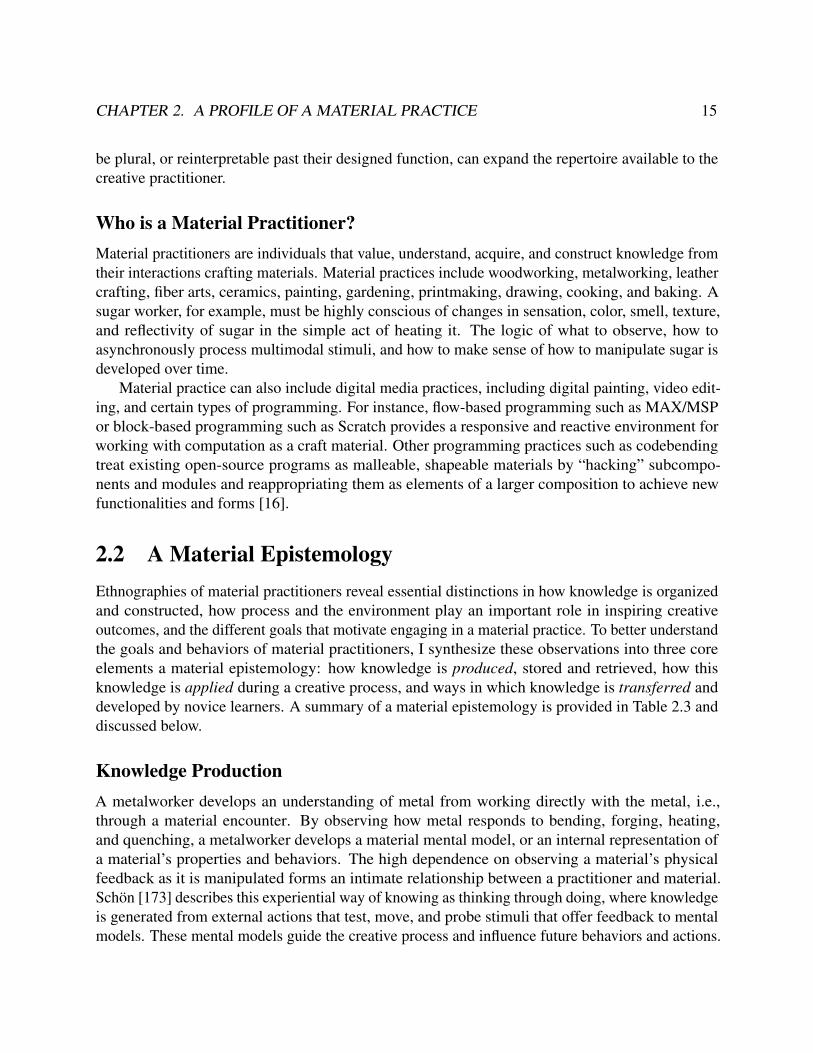
2.1 (Left) A wall of a potter’s studio holds tens of firing keys that each record the resultsof a firing of a unique clay body and glaze combination. The potter externalizes theirmental model of the firing process onto her environment, grabbing a set of keys whendeciding how to glaze her latest work and guiding her creative process. (Right) Thekeys each display a firing temperature and a patterned print used to mark and identifyfinished pieces2. . . . . . . . . . . . . . . . . . . . . . . . . . . . . . . . . . . . . . 17
2.2 A Stained Glass Process. A glassworker cuts and grinds geometries from a pane ofglass material which is often risky and error-prone. The glass geometries are lined withcopper tape and soldered together. The skill of applying heat at the correct location, rate,and duration is tacit and developed experientially over time. The different resistancesfound in each material for forming processes introduced a value system. For glass,cutting textured glass results in more compositions that display a mastery of the mediumthan those with smooth glass3. . . . . . . . . . . . . . . . . . . . . . . . . . . . . . . 20
2.3 (top) Hylomorphic making in a stained glass practice – a cartoon is used to plan acomposition, and glass it cut to match the design until the design matches the cartoon.(bottom) Hylomorphic making in Fused Deposition Modeling (FDM) 3D printing – anabstract form is imagined and specified as an STL model; the resulting form is imposedupon a host of different materials in a filament form factor; the form is consideredcomplete when it matches the target model4. . . . . . . . . . . . . . . . . . . . . . . 22

vi
2.4 The traditional CAD-CAM workflow. In the computer-aided design phase, a computa-tional model is constructed using a modeling tool and typically exported as a watertightmesh (STL) or as curves (SVG). In the computer-aided manufacturing phase, the en-coding is converted into a machine-interpretable geometry, a tool-path is then plannedto satisfy that geometry, and the compiled set of instructions is then communicated to acomputer numerical control tool. The CAM process is device-specific and needs to berun for each CNC tool. . . . . . . . . . . . . . . . . . . . . . . . . . . . . . . . . . . 23
2.5 (Left) A 3D print has experienced lift-off, a printing error that occurs when thermoplasticcontracts and introduces internal stresses to the model. The common fix is to applyglue to the printing platform for stronger adhesion to overcome forces from contraction.(Right) A clay vase is wrapped in multiple different bags to control the drying rate ofthe clay. Drying too quickly can introduce internal stresses on the walls of the vaseand cause fractures. The plastic bags are progressively removed, exposing thinner,faster-drying geometries first5. . . . . . . . . . . . . . . . . . . . . . . . . . . . . . . 25
3.1 Translators: (left to right) translating sculpting actions [176]; translating markers [169];translating measurements [205]. . . . . . . . . . . . . . . . . . . . . . . . . . . . . . 29
3.2 Mediators: (left to right) mediating code [159], mediating signal [154], mediating airflow [199], compositing smart materials [99]. . . . . . . . . . . . . . . . . . . . . . . 30
3.3 Monitors: (left) monitoring carving actions [225], (right) monitoring cutting actions [218].. . . . . . . . . . . . . . . . . . . . . . . . . . . . . . . . . . . . . . . . . . . . . . 30
3.4 Armatures: (left to right) supporting weaving [223], supporting painting [14], supportingwearable modeling [56]. . . . . . . . . . . . . . . . . . . . . . . . . . . . . . . . . . 31
3.5 (left) Lilypad Arduino [23]; (center) Chibitronics [156]; (right) E-textiles tester [153] . 32
4.1 Immaterials are elements that are difficult to perceive or manipulate by the human bodyunaided. . . . . . . . . . . . . . . . . . . . . . . . . . . . . . . . . . . . . . . . . . . 41
4.2 Daniel Rozin. Wooden Mirror (1999). 830 square pieces of wood, 830 servo motors,control electronics, video camera, wood frame. Size - W 67” x H 80” x D 10” (170cm ,203cm, 25cm). . . . . . . . . . . . . . . . . . . . . . . . . . . . . . . . . . . . . . . 41
5.1 The CAD-CAM pipeline. Sketches or prototypes are converted into a computationalrepresention using a modeling tool. The tool then encodes this representation in aform that is accepted by CNC machines. This representation is translated into machine-specific instructions and sent to a CNC machine for fabrication. Many machines produceartifacts that require some post-processing. . . . . . . . . . . . . . . . . . . . . . . . 46
5.2 Proxy-Mediated Practice. 1) A wire-wrap jewelry design is converted into a computa-tional representation, 2) this representation is translated into an armature, or tool, thathelps with making the target design, 3) the armature allows for a material encounter tooccur while still providing the benefits of digital fabrication. . . . . . . . . . . . . . . 47
5.3 Tools of the Trade. Pliers, jigs, mandrels, vises are commonly used in wire-wrappingand are often custom-made for specific jewelry designs.6 . . . . . . . . . . . . . . . . 48

vii
5.4 Comparison against WrapIt [82] . . . . . . . . . . . . . . . . . . . . . . . . . . . . . 505.5 ProxyPrint Computational Design Tool for Wire-Wrapping. ProxyPrint Computational
Design Tool for Wire Wrapping. Users can drag common forms onto a canvas, ma-nipulate paths, specify materials, and add ornamentation and connections. The toolproduces a heightmap used to generate a 2.5D printable proxy. . . . . . . . . . . . . . 51
5.6 Wire-shaping strategies. Opening and closing a jump ring using (top) axial bends and(bottom) lateral bends. Note the deformations that arise from lateral work-hardening. . 55
5.7 How to Use a Shape Proxy . . . . . . . . . . . . . . . . . . . . . . . . . . . . . . . . 575.8 Routine for Shape Proxy Generation. . . . . . . . . . . . . . . . . . . . . . . . . . . 585.9 Deformations of a Heart Shape along the Axial Dimension . . . . . . . . . . . . . . . 585.10 Hill Climbing Path . . . . . . . . . . . . . . . . . . . . . . . . . . . . . . . . . . . . 595.11 Proxy Shape Primitives . . . . . . . . . . . . . . . . . . . . . . . . . . . . . . . . . . 605.12 Three different proxies, or tools that aid users in the construction of an artifact, with
different profiles of assistance. A schematic (left) provides fabrication feedback via anannotated construction proxy; a stencil (center) breaks down designs into elementaryforms, c) a jig (right) provides a ritual high-fidelity fabrication process via a fabricationand construction proxy. . . . . . . . . . . . . . . . . . . . . . . . . . . . . . . . . . . 61
5.13 Proxy Scaffold - Jig . . . . . . . . . . . . . . . . . . . . . . . . . . . . . . . . . . . . 625.14 Proxy Scaffold - Stencil . . . . . . . . . . . . . . . . . . . . . . . . . . . . . . . . . . 635.15 Proxy Scaffold - Schematic . . . . . . . . . . . . . . . . . . . . . . . . . . . . . . . . 645.16 Study Setup . . . . . . . . . . . . . . . . . . . . . . . . . . . . . . . . . . . . . . . . 675.17 Questionnaire Results . . . . . . . . . . . . . . . . . . . . . . . . . . . . . . . . . . . 695.18 Flow as a measurement of engagement. The boxplot depict the difference in perceived
and actual completion time. Areas in the texture ‘+’ field indicate the participant losttrack of time. . . . . . . . . . . . . . . . . . . . . . . . . . . . . . . . . . . . . . . . 70
5.19 Construction patterns were highly dependent on the first scaffold that was presented toparticipants. Schematic-first users moved with step-wise similarity, jig-first followed alinear progression, while stencil-first compartmentalized forms – an expert trait. . . . . 71
5.20 Wire-wrap Artifacts of Expert Participant 4 . . . . . . . . . . . . . . . . . . . . . . . 72
6.1 @ThePracticalDev Community - O’rly Book Cover Generator . . . . . . . . . . . . . 776.2 Luminaire Design Tool, Simulation Interface, and Fabricated Luminaire . . . . . . . . 786.3 (left) Olafur Eliasson, The Weather Project (2003), (center) Daniel Rozin, Wooden
Mirror (1999), (right) Printed Optics [210] . . . . . . . . . . . . . . . . . . . . . . . . 796.4 (left) Jim Campbell, Exploded Views (2011), (center) László Moholy-Nagy, Light-Space
Modulator(1930), (right) Gjon Mili, Picasso draws a centaur (1949) . . . . . . . . . . 806.5 Adafruit LED Matrix (1613)7 . . . . . . . . . . . . . . . . . . . . . . . . . . . . . . . 826.6 The Matrix Circuit Pattern. A circuit pattern for selectively controlling an LED. . . . . 836.7 Luminous LED Strip Light, a commodity smart LED strip8. . . . . . . . . . . . . . . 84

viii
6.8 A lamp of the Virgen de Guadalupe cast in resin and inlaid with fiber optics. (center) Amechanical stepper motor rotates a stained glass disk above a lamp bulb; fiber opticscapture the colored light acting as a sequencer. (right) A light sequencer program;the fiber optics bundle "reads" in light passed through a colored disk. Manufacturerunknown. . . . . . . . . . . . . . . . . . . . . . . . . . . . . . . . . . . . . . . . . . 87
6.9 An LED was cast in acrylic resin (PMMA) using a packing plastic as a mold. As theresin cured, gases produced from the chemical reaction attempted to escape but werecaptured, forming bubbles. Light emitted from the LED interacts with these geometries,refracting and reflecting to form light gradients, shadows, and textures. . . . . . . . . 88
6.10 Luminaire Construction - Lamps are housed, powered, and controlled in the base level.Secondary optic elements in the beam-shaping layer shape light emitted from the lamps.The topmost diffuser controls the presentation of light using light-scattering surfaceproperties9. . . . . . . . . . . . . . . . . . . . . . . . . . . . . . . . . . . . . . . . . 91
6.11 Trace assistance routine. a) user annotates SVG, b) positions are extraced and LEDorientation is optimized, c) optimal path is extracted, d) design files produced for severalprocesses, e) different substrates can be used to create rigid or flexible PCBs. . . . . . 92
6.12 Parametric Models of Secondary Optic Systems. A scene is constructed with a lightsource (yellow), reflective materials (red), non-reflective materials (black), refractivematerial (light blue), and diffusive material (green). . . . . . . . . . . . . . . . . . . . 93
6.13 Shape-Optimized Secondary Optic Element Pipeline . . . . . . . . . . . . . . . . . . 946.14 Simulated Annealing . . . . . . . . . . . . . . . . . . . . . . . . . . . . . . . . . . . 956.15 Fabricated reflectors. A total internal reflection (TIR) reflector printing in clear resin
(left). Light enters through an air cavity above the LED and is reflected internally,spreading light throughout the lens. A parabolic reflector printing in clear resin, with acoat of mirror spray and acrylic coating (right). . . . . . . . . . . . . . . . . . . . . . 96
6.16 LED Diffuser . . . . . . . . . . . . . . . . . . . . . . . . . . . . . . . . . . . . . . . 976.17 Polar Luminous Intensity Graph. The diagram indicates the distribution of the relative
luminous intensity of the luminaire. Control systems are marked with dashed lines.Each reflector condition has a 40% glass by mass 3 mm diffuser. . . . . . . . . . . . . 98
6.18 Luminaire Creation Pipeline. a) Given an SVG graphic, our luminaire design toolaids users with laying out LEDs, visualizing light interactions, and specifying targetareas to fill with light. In the callout, an LED is specified to fill a moon-shape. b) Acomputational design backend generates an optimal secondary optics system to achievethe desired design using ray tracing to guide a simulated annealing search. All filesfor 3D printing geometries and milling circuits are produced by the backend, c) aninstruction set guides the user to assemble the luminaire. . . . . . . . . . . . . . . . . 99
6.19 Illumination views. Each view can be toggled by a user when composing their design toshowcase different illumination concerns. Each light source interacts with neighboringgeometries and shows light interactions such as mixture and shadow creation. . . . . . 99
6.20 Illuminated Hair brooch (1 LED) . . . . . . . . . . . . . . . . . . . . . . . . . . . . 1006.21 Sun Moon Lightwork (25 LEDs) . . . . . . . . . . . . . . . . . . . . . . . . . . . . . 1016.22 Tactile Cityscape (16 LEDs) . . . . . . . . . . . . . . . . . . . . . . . . . . . . . . . 102

ix
6.23 Haptic Button (1 Blue LED, 1 Green LED) . . . . . . . . . . . . . . . . . . . . . . . 1026.24 Luminaires fabricated from user designs: (top) simulated results from the luminaire
design tool, (bottom) the final physical luminaire. . . . . . . . . . . . . . . . . . . . . 1036.25 Participant 170 - Owl Luminaire . . . . . . . . . . . . . . . . . . . . . . . . . . . . . 110
7.1 A Thermoreactive Composite. Thermochromic pigments are bound in gum arabic,giving it many of the same qualities as watercolor paints. A purple thermochromicglaze is applied to a chromostable watercolor composition depicting an apple. A silverink resistive heater is coupled to the composition with Kapton tape; when triggered, itproduces a dynamic ripening-apple illustration. . . . . . . . . . . . . . . . . . . . . . 114
7.2 Parameters of a Thermoreactive Composite - The power supply and silver ink circuitare used to form a joule heater. This heater is inserted into the cuff of a sleeve with ascreenprinted thermoreactive design made with liquid crystal paint. . . . . . . . . . . 118
7.3 Designing Heat Regions and Activation Times. A user draws an initial heat region (perthe dimensions of the cuff design), subdivides the region into 5 using a widget, andspecifies desired activation times. A computational model updates and computes thepower specification. . . . . . . . . . . . . . . . . . . . . . . . . . . . . . . . . . . . 119
7.4 Trace Design. Circuit design variables are queried from the circuit model for each heatregion and a serpentine pattern is generated, specific to silver ink, to achieve the targetresistance and power. . . . . . . . . . . . . . . . . . . . . . . . . . . . . . . . . . . . 119
7.5 Characterization Routine. . . . . . . . . . . . . . . . . . . . . . . . . . . . . . . . . . 1207.6 Activation Energy of Various Thermoreactive Composites . . . . . . . . . . . . . . . . 1217.7 Capturing Parameters of Thermoreactive Composites . . . . . . . . . . . . . . . . . . 1227.8 Capturing a Thermoreactive Composition. An image is transferred through a network
connected camera, processed through the web app, and transferred to form the backdropof the design canvas. . . . . . . . . . . . . . . . . . . . . . . . . . . . . . . . . . . . 123
7.9 Design Stage Concerns. Given a set of material parameters, the design stage allows auser to specify regions to heat and when to activate thermoreactive materials in thoseregions. . . . . . . . . . . . . . . . . . . . . . . . . . . . . . . . . . . . . . . . . . . 123
7.10 Resistive Heater Design Workflow. Four different views walkthrough the design stageinteractions: a thermal view facilitates drawing heat regions and specifying heat regionparameters, a circuit view aids with generating and adjusting serpentine patterns, atemporal view plays back a simulation of the heater design, and a print view presents thefinal circuit design; the design can then printed, adjusted in Illustrator, or incorporatedinto more complex circuits. . . . . . . . . . . . . . . . . . . . . . . . . . . . . . . . . 124
7.11 Fabrication Workflow. Heaters are fabricated and validated with a TLC sheet. ThePhosphenes web app provides debugging assistance. . . . . . . . . . . . . . . . . . . 124
7.12 Digital Perceivability Mechanisms. The generated circuit and underlying circuit modelare used to encode an interactive visual representation of circuit state, including powerconsumption, current distribution, and resistance. A digital stitching interaction re-quires physical effort to produce traces, while a splashing-rock modeling analogyconceptualizes electric heat. . . . . . . . . . . . . . . . . . . . . . . . . . . . . . . . . 126

x
7.13 Circuit Model and Thread Model Updates. The spool drains as more current is drawnto respective subheaters. . . . . . . . . . . . . . . . . . . . . . . . . . . . . . . . . . 127
7.14 Physical Perceivability Mechanisms. (top) Liquid crystal sheets with the aid of a coldplate to reset activated materials serve as an iterative heat evaluation technique. (bottom)A TrC sleeve activates from left to right, serving as a wearable progress bar and dynamictexture. . . . . . . . . . . . . . . . . . . . . . . . . . . . . . . . . . . . . . . . . . . 128
7.15 Thermodynamic Painting Techniques . . . . . . . . . . . . . . . . . . . . . . . . . . 1297.16 Thermodynamic Watercolor . . . . . . . . . . . . . . . . . . . . . . . . . . . . . . . 1297.17 The Buddha Mala . . . . . . . . . . . . . . . . . . . . . . . . . . . . . . . . . . . . . 1307.18 Liquid Crystal Collar and Cuff Wearable Display . . . . . . . . . . . . . . . . . . . . 1317.19 Liquid Crystal Handbag with Underlying Copper Foil Heat Conductors . . . . . . . . 1327.20 Thermochromic PLA Embossed Coaster . . . . . . . . . . . . . . . . . . . . . . . . 1327.21 A Thermoreactive Print. (a) A silver ink resistive heater is placed inside a thermoreactive
3D print, (b) the thickness of the 3D-printed walls is used to modulate the mass incontact with the uniform heat source in the interior, (c) the thinner walls activate first,creating a windowing effect. . . . . . . . . . . . . . . . . . . . . . . . . . . . . . . . 133
7.22 Workshop Heaters. Participants were tasked with creating a heater that would make 3or more circles disappear from a thermochromic watercolor composition. . . . . . . . 135
7.23 CSI Index Results . . . . . . . . . . . . . . . . . . . . . . . . . . . . . . . . . . . . 1377.24 Haptic Retargeting. Glass-blowing practices use heat in ranges that far exceed current
Thermoreactive Composites (TrCs). How might retargeting these haptic cues affectcreative practices? . . . . . . . . . . . . . . . . . . . . . . . . . . . . . . . . . . . . 141
7.25 Copper Heat Smoothing. (left) A two-branch joule heater activates a TLC sheet; (right)a thin-sheet of copper is placed over the original heater, smoothing out the serpentineheat pattern. . . . . . . . . . . . . . . . . . . . . . . . . . . . . . . . . . . . . . . . 142
7.26 Could shaping three-dimensional wire forms created three-dimension heat forms? . . 143
8.1 Crafting Proxy Design Method . . . . . . . . . . . . . . . . . . . . . . . . . . . . . . 1458.2 A simple light simulation of LEDs in a California Bear reflector geometry. (left) A
Cool Simulation - Low-definition media that engages the senses less completely; (right)A Hot Simulation - High-definition media. . . . . . . . . . . . . . . . . . . . . . . . 149
8.3 Semiotics of Traditional Materials. (left) Virgén de Guadalupe Fiber Optic Lamp, (cen-ter) Phosphenes Buddha Mala, (right) Illumination Aesthetics Illuminated Hairbrooch
. . . . . . . . . . . . . . . . . . . . . . . . . . . . . . . . . . . . . . . . . . . . . . 1518.4 Proxies for Biomaterials10 . . . . . . . . . . . . . . . . . . . . . . . . . . . . . . . . 1558.5 Proxies for Electromagnetism11 . . . . . . . . . . . . . . . . . . . . . . . . . . . . . . 155
9.1 Computational Design Architecture . . . . . . . . . . . . . . . . . . . . . . . . . . . 1589.2 2D Design Specification . . . . . . . . . . . . . . . . . . . . . . . . . . . . . . . . . 1609.3 SVG as Input Parameters . . . . . . . . . . . . . . . . . . . . . . . . . . . . . . . . . 1619.4 2.5D Model Generation - Mold Generation . . . . . . . . . . . . . . . . . . . . . . . 162

xi
9.5 SVG as Service Registry - The SVG encodes the IoT devices in a scene and exposesavailable services (e.g., sensing, actuation) that can be accessed by a web application. 164
10.1 Where can the interface exist in a material environment?12 . . . . . . . . . . . . . . . 16810.2 Settables: Shapeable viscoelastic materials that can be set into a final form.13 . . . . . 16910.3 Sites for Material Interfaces. (left) a deformable and haptic interface (piping bag) is
used to deposit frosting onto the surface of a cake; (right) a surface with continuousinteraction with the skin (foot pedal) is used to control a sewing machine.14 . . . . . . 170
10.4 Retargetting Data. (left) Movement of a soldering iron and interactions with a spongeare converted into sonic cues; (right) Data from an infrared camera is converted into avisual stimulus while thermoforming an acrylic bar. . . . . . . . . . . . . . . . . . . . 171

xii
List of Tables
2.1 Components of a Material’s Conversational Profile . . . . . . . . . . . . . . . . . . . 142.3 The Profile of a Material Epistemology . . . . . . . . . . . . . . . . . . . . . . . . . . 16
6.1 A Conversational Profile of Light . . . . . . . . . . . . . . . . . . . . . . . . . . . . . 906.2 Qualitative Assessment Luminaire Design Tool and Fabricated Luminaire Objects . . . 103

xiii
Acknowledgments
I am incredibly fortunate to have had Eric Paulos as an advisor. He taught me to step out of thebox, embraced my interdisciplinary quirks, and fostered such an open, inclusive, and creativeenvironment at UC Berkeley.
I am incredibly indebted to my colleagues for their insight, knowledge, and expressiveness.Thank you Rundong Tian, Molly Nicholas, Christine Dierk, Sarah Sterman, Joanne Lo, JamesPierce, Laura Devendorf, Vedant Seran, Katherine Wu, and especially Tim Campbell, my researchcompadre, who endured the early research years with me.
This work would not have been possible without the talented undergrads that have enduredmy mentorship. Thank you Jasper O’Leary, Jessica Chang, Advaita Patel, Emily Hill, Tina Taleb,Matthew Jörke, Sangyeon Lee, Tony Zhao, Neil Kumar, Connor Freeman, Alejandro Garcia Salas,Jaqueline Garcia, Niraj Rao, Ryan Kapur, Emily Chao, and Akhila Raju.
I am thankful for the support of my committee members: to Kimiko Ryokai, whose coursesplanted the initial seeds towards researching tangible computing, creativity, and learning; to BjörnHartmann whose inspirational work in design tool research motivated me to pursue this dissertationtrajectory. A special thanks to Adobe Research for supporting my research, especially my mentorsWilmot Li and Mira Dontcheva.
The New Media program at Berkeley has been invaluable to who I am as an academic. I amgrateful to have been part of the community and thank the people who made it what it is today,especially Gail de Kosnik, Greg Niemeyer, Ken Goldberg, Lara Wolfe, Nicholas de Monchaux, andJill Miller.
To the BiDizens: Thank you for the incredible support network and valuable feedback. Thanksto Drew Sabelhaus, Elena Durán, Kristin Stephens-Martinez, Pablo Paredes, Valkyrie Savage,Andrew Head, Jeremy Warner, Eldon Schoop, Nate Weinman, Hezheng Yin, Deniz Dogruer, JuliaKramer, and Peggy Chi.
I am thankful to have received critical perspectives from the iSchool. Thanks to Noura Howell,Richmond Wong, Nick Merrill, and Marti Hearst.
Un mil gracias a mi familia, mi esposo José Buenrostro, mis papas César y Rosa, mis suegrosFran y Noemi, mi hermana la Dra. Brenda Torres, mis cuñados Estevan Mendoza y DonaldoBuenrostro, y mis amigos Katie Campbell, Laura Campbell, y Jim Campbell.
Lastly, to the inspiration behind it all – Frida Kahlo – whose artwork pushed the boundaries ofaccepted aesthetics and who embodied this philosophy in her life and being.
1
Chapter 1
Introduction
Someday artists will work withcapacitors, resistors, andsemiconductors as they work todaywith brushes, violins & junk.
Nam June Paik [141]
Creative technologies like digital fabrication1 led to the rise of the Maker movement, engenderinggrassroots innovation in education, manufacturing, healthcare, and beyond [61, 130]. Today, thesecreative technologies stand at a crossroads – despite a rise in participation from lowering bothtechnical and social barriers, there remains a gap between literacy, fluency, and competence [18].Digital fabrication democratizes access to a variety of materials, processes, and techniques, butachieving fluency, or the “[intellectual] capabilities [to] empower people to manipulate the mediumto their advantage and to handle unintended and unexpected problems when they arise” continues tobe a pedagogical challenge [18]. In The Art of the Maker [41], Dormer describes this paradox ofdemocratization – while skills are made available to a practitioner without needing to acquire them,it also confines a practitioner to other people’s way of thinking. For makerspaces oriented aroundScience, Technology, Engineering, and Math (STEM) fields, the proclivity of machines to removethe human hand from interactions with the physical material, eliminate the need for manual dexterity,and reduce the risk of human error is deeply rooted in manufacturing practices. This manufacturinglegacy develops an epistemological monoculture that permeates through many makerspaces. Thisis not to make a blanket statement that no makerspace has achieved inclusivity or diversity ofthought, but instead to point to intrinsic workflows that are deeply seated in mass-manufacturingvalues. In valuing “product” over “process,” knowledge remains blackboxed while replication andreproduction drive creative interactions, limiting the agency of the maker and the motivation forcreative exploration [18].1 Definitions for terms, concepts, and abbreviations used throughout this dissertation have been made available in
the Glossary (Appendix E).

CHAPTER 1. INTRODUCTION 2
Figure 1.1: (left) The Coiling Method. A pottery technique developed across cultures and time periodsthat additively deposits material to build free-standing 3D forms. (right) Fused Deposition Modeling. A3D-printing technique developed in 1989 that additively deposits material to build free-standing 3D forms2.
As a motivating example (Figure 1.1), consider the core technology behind 3D Printing – FusedDeposition Modeling (FDM) [34]. Developed in 1989 by Statasys, Inc. the technique involvesusing a movable extruder to deposit material that self hardens over time, bonding from contact withpreviously extruded elements. Layer by layer, this coil of material accumulates to form a final 3Dgeometry. This technique bears a striking similarity to the Coiling Method, a ceramics techniquethat has developed across cultures dating back to at least 2500 BC. In the Coiling Method, a pieceof clay is rolled into a tube, similar to the form one might encounter extruding from a 3D printer. Aceramicist then scores the tube (creating a rough texture) and applies a slip (a watered-down clayglue) on the contact points where the tube will “fuse” as it winds around proximal tubes.
Despite Fused Deposition Modeling (FDM) being portable to a variety of materials includingclay [1], 3D printing workflows run counter to sculptural thinking (creating 3D forms) or even claythinking (creating with clay), preventing digital fabrication practices access to the thousands ofyears knowledge embedded in these practices.
• What might 3D printing have to gain from integrating the thousands of years of knowledge,tradition, and culture of clay-based “3D printing”?
• What might digital fabrication look like if ceramicist could also inform the design of thesefuture technologies and spaces?
• How might ceramics as a discipline transform from a deeper engagement with computation,or digital fabrication from a deeper engagement with clay?
Envisionment. While I pose these questions centered around clay, I envision a future wheredigital materials like neural networks, data, and signals sit alongside a host of physical materials.2 Image credits [left to right]: Bridges Pottery, from https://youtu.be/2dsOf2uj3Zw; Alene Sirott-Cope, from
https://www.pinterest.fr/pin/73253931415662977/; Ahn et al. [4]; Monochromatic Vase by Devin Monteshttps://www.devinmontes.com/.

CHAPTER 1. INTRODUCTION 3
The aim is not to replicate our virtual way of making, but to discover how an embodied virtualitychanges what we choose to make and who participates in making. I imagine these emergingpractices developing hybrid aesthetics that operate outside of the prevailing traditions of digital orphysical mediums but instead develop a new idea of what technology looks like. Much like we sawEva Hesse [115] in the 1970s breaking the male-dominated sculptural practices of stone, metal,and wood, forming instead soft latex skins of “everyday materials” with cheesecloth and nets, orTurkle and Papert [196] breaking the notion of a singular way of thinking in computer science, Iimagine digital fabrication taking on a new meaning where a makerspace is not a “collection offabrication machines in a small workshop” [203], but a community of practitioners deeply engagedwithin a sociocultural practice. When designing digital fabrication technologies, like a 3D printer,the process it facilitates should not be abstracted and generalized to fit all, but instead be designedfor reappropriation, allowing a community of practice to align digital fabrication with their valuesystems. I see the environments that support this new type of making relegating the screen to thebackground and instead engaging and enhancing the human body’s role in the creative process.Most importantly, I hope for creative technology to change its current dynamic of making noveland interesting objects, to instead prioritize cultivating agency, resiliency, and self-efficacy for past,current, and future practitioners to sustain a lifelong practice.
1.1 Problem DefinitionFor Human-Computer Interaction (HCI), it is not enough to simplify programs or develop stream-lined software and hardware tools. For digital fabrication to reach the vision of personal fabrication,fabrication practices must support a more plural way of thinking [72]. I am specifically interestedin supporting material crafting practices, henceforth referred to as material practices, that workwith materials using a specific set of skills, methods of reflection, and the potential to achievemastery [135]. I aim to develop a digital fabrication practice that is diametrically opposed to thegoals of mass reproduction, building on historical antecedents to the Arts and Crafts movement(1880-1920) forming as a response to the impersonal and mechanized ideals of the IndustrialRevolution (1760-1840) [211]. There are several contributing social, cultural, and technical factorsthat have influenced the limited intersection of digital fabrication with material practices, which Idescribe below. These tensions are discussed in detail in Chapter 2.
• Aesthetic Pluralism. Aesthetics refer to the philosophical analysis of the beliefs, concepts,and theories implicit in the creation, experience, interpretation, or critique of art (qtd. in [49]).Although a concept from art theory, aesthetics have widespread impact across disciplines.A minimalist aesthetic, for example, arose from a belief in clarity and intentionality andhas influenced both art production, social forms, and interaction design towards removingartifacts or interactions that detract from a central message.
Material practitioners must negotiate whether they can maintain a craft identity when work-ing with methods and aesthetics that “sit more comfortably with mass manufacturing thancraft” [72].

CHAPTER 1. INTRODUCTION 4
• Workflow Pluralism. Digital fabrication practices arising from engineering differ fromworkflows in practices within art, anthropology, architecture, and archeology [85]. Whilesome practices are goal-oriented, others are exploratory. Simple actions, like arriving at amakerspace without a preconceived idea or plan of action conflicts with the demand andlimited resources makerspaces can provide.
The de facto fabrication workflow, the CAD-CAM pipeline, separates design and fabricationinto two distinct steps: creating a computational representation of form, then converting thisrepresentation into machine instructions for fabrication. Current trends with multi-material 3Dprinting suggest an aim to remove interactions with materials altogether. However, materialencounters, or the experiential creation of mental models from interactions with a material,are central to a material practice. The need for direct engagement with materials conflictswith the need to contain material processes in the CAD-CAM pipeline. Material practicesare physically messy – a characteristic that conflicts with computers and electronics. Evenabstracting the material and mediating the experience of interacting with a material has itslimits, running into the classic dilemma of simulacra – the case in which the simulation willindubitably continue to neglect an important element of the real world [103].
• Knowledge and Domain Transfer. In order to work with a Computer Numerical Control(CNC) machine or a Computer-Aided Design (CAD) program, a material practitioner mustlearn an entirely new way of thinking (e.g., CAD thinking) which displaces the years ofpractice and skill they have developed. For instance, CAD programs oriented towards noviceslike TinkerCAD [8] use Constructive Solid Geometries (CSGs) to provide an elementaryvocabulary of forms and operations (e.g., unite, subtract). This way of making 3D formsreadily transfers to additive and subtractive sculpture practices, but does not support thewider repertoire of ceramics 3D forming techniques like coil, slab, or slip-casting methods.This tension from being unable to access the complete repertoire of skills echoes calls tosupport thick practice, allowing for the continuity of practice and supporting skills thathave been acquired over time by using common physical interfaces as opposed to digitallymediating them [103]. Furthermore, an element of facilitating domain transfer involvesfinding instructional resources. When building on uneven skillsets, the ability for materialpractitioners to find an instructor or a peer to serve as one remains a challenge [184].
• Maintenance Many complex machines exist in material practices, and although they maybreak, longstanding practices have alternative methods (e.g., by hand) to achieve proximalresults. Building trust in the continuous operation of ubiquitous computing devices is a centralchallenge in the home [44]. In digital fabrication spaces, a malfunctioning wireless router canquickly decommission the space; such brittleness in digital fabrication technologies limits thereliance and trust material practitioners place on these tools in their creative practice.
• Inclusivity. The maker identity has a deeper history with hacker culture and is associated withfields like engineering and computer science, largely composed of educated white men [105].With the introduction of MAKE magazine and regional MakerFaires, the maker identity

CHAPTER 1. INTRODUCTION 5
has since developed to include children but remains predominantly male and middle class.In a content analysis of 10 years of magazine covers of MAKE magazine, Buechley [22]reported that only 14% featured women had been featured on the color, with no representationof Black makers. This strong association of digital fabrication with the STEM fields andmale-dominated practices influences the kinds of objects that produced, what is valued withinthe community, and their ways of making. As Rosner & Fox [163] describe, some com-munities have formed “alternative” makerspaces such as the women-organized hackerspaceHackerMoms which incorporates craft processes like Failure Clubs that recognize and supportthe vulnerability of failure. These collectives also break traditional notions of hackerspaces,occurring in spaces that do not read as commercial fabrication workspaces, but instead asliving rooms [163].
Thesis TenetsTo counteract these factors, I pose the following tenets for bridging material practices and digitalfabrication and supporting material practitioners:
Tenet 1 Material practitioners should be able to access and incorporate the years ofknowledge from their respective practices within digital fabrication workflows.
Tenet 2 Material practitioners should be able to use computation, electronics, andother emerging technologies like they would any other material. Such materialsshould be approachable and match their methods of producing, storing, applying,and transferring knowledge.
1.2 Significance and Broader ImpactsIn digital fabrication, the 3D printer is just the first of many new practices where we see thecomputation inching closer to being a part of physical practices. Bridging material practice anddigital fabrication has the potential to diversify how we encounter, experience, and interact withcomputation which I detail below.
Developing Communities of Practice (CoPs). In this work, I use the term creativity to referto the social definition of creativity: “ideas and discoveries in everyday work practice that arenovel with respect to an individual human mind or social community” (qtd. in [48]). Framingcreativity as a social action is an important component of Communities of Practice (COPs) sincematerial practitioners often organize into communities of people in a certain domain undertakingsimilar work. However, digital fabrication communities of practice are still nascent, but they areradically changing how creative work is being evaluated and appreciated. For instance, for novicedigital fabrication users entering the community, computational design engines (e.g., support vector

CHAPTER 1. INTRODUCTION 6
graphics, parametric design, generative design) and repositories (e.g., online galleries, curatedcollections) lower the barrier to entry and minimize the risk of engaging with digital fabricationmachines, but there are fewer mechanisms in place to sustain that practice. When a novicepractitioner downloads and prints a 3D model from an online repository, the social evaluation andappreciation of such work within the CoP is devalued, whereas that same work to those outsidethe community is highly valued. Thus, for the novice practitioner, it is more rewarding to remainoutside the CoP.
I argue that social appreciation by a community of practice is a central component to themotivations that drive aesthetics. In bridging these two communities of practice, I see emergingdigital fabrication practices benefiting from mature mechanisms for supporting social creativity. Forexample, the painting art practice community has established a tradition of working with a medium(e.g., figure/ground), a value system on which to evaluate a painting (e.g., minimalism), and socialand cultural mechanisms for developing expertise with the medium (e.g., critique, public exhibition,starving artist, lone creative genius). Supporting material practitioners like painters to enter thedigital fabrication community can act as a way for new value systems to emerge that alter themotivations for what is valued and produced, leading to innovative design and ideas. Furthermore,many material practices readily integrate critique of society and culture and engagement with ethicswithin their value systems – elements which have growing relevance as technology interfaces with alarger breadth of human activity.
Technology Adoption and Participation. Aesthetics have a significant impact on technologyadoption. Especially as we encounter interfaces in our surroundings, clothing, bodies, and cities,allowing material practitioners to inform how we perceive and interact with these technologies candemocratize future trajectories beyond the reach of a single discipline. Material practices are alsomore approachable than engineering practices and carry more profound benefits of self-identityand self-efficacy formation that forms the tenet of their integration with Science, Technology,Engineering, Art, and Math (STEAM) pedagogy [120]. Moving past a superficial integration of Artand STEM, developing tools around material epistemologies aligns with initiatives in broadeningparticipation in computer science and STEM fields.
Future Materials and Techniques. The landscape of materials, technologies, and fabricationtechniques are quickly evolving. A user interface designer in the twenty-first century must notonly be competent in working with computation and screen but be fluent in working with a widerrepertoire of materials to be able to design for non-traditional sites of interaction (e.g., on skin,clothing, and surroundings). Material practices have a rich repertoire of techniques that are easilyportable to new materials. Accessing and integrating techniques in established practices is onemethod of disseminating, advancing, and creating New Media practices.

CHAPTER 1. INTRODUCTION 7
1.3 ContributionsThis dissertation contributes to a design method for bridging material practices and digital fabrica-tion, composed of:
• A Profile of a Material Practice This work synthesizes theory around craft, aesthetics, andmaking with ethnographies of material practitioners. It compiles a profile that decomposesmaterial epistemology into three components: knowledge production, knowledge application,knowledge tranfer. This profile serves as an analytical tool to assess the capacity for tools tosupport a material epistemology.
• The Concept of the Crafting Proxy I introduce the concept of a Crafting Proxy – anintermediary between a practitioner and a material that can be used to facilitate interpretation,manipulation, and evaluation of a material as a part of a creative process. A Crafting Proxy isa type of creativity support tool that falls under a structuralist approach to creativity [180] –facilitating a method or process as a means of enhancing creativity. Crafting Proxies aim tosupport a material epistemology and are designed to facilitate material encounters, encouragewayfaring behaviors, and incorporate horizontal learning structures for more diverse anddemocratic forms of knowledge transfer. I synthesize intermediate-level knowledge gainedfrom developing design tools that facilitate digital fabrication techniques with materials (wire)and immaterials (light and heat).
• A Generalized Compositing Method. This work generalizes the compositing design strat-egy employed for computational composites to inform how other emerging materials, besidescomputation, can be designed to be used by material practitioners. I describe analytical andethnographic methods for extracting the conversational profile of a material, computationaldesign algorithms for improving its composability or malleability, and the development ofperceivability mechanisms used to reinforce material mental models. I synthesize workshopevaluations and artifacts build across three domains into design principles for navigating theCrafting Proxy design space.
As a result, the design method laid out by this work offers practical direction for composingnew materials and technologies to foreground the existing knowledge and practices of materialpractitioners and generate new forms and aesthetics that can alter the trajectory of the Makermovement towards a New Making Renaissance.
1.4 OutlineThis dissertation walks through important concepts around crafting theory, describes a series ofprojects that probe different areas of the Crafting Proxy design space, and culminates in a designmethod and a set of design principles. The document is organized as follows:
First, in Chapter 2, I argue for the need to better describe a material practitioner’s “way ofknowing,” or epistemology. I present a profile of the material practitioner, synthesized from research

CHAPTER 1. INTRODUCTION 8
literature in anthropology and ethnography [172, 175, 85, 162, 194] and describe who materialpractitioners are, how they work and create, and the challenges they encounter when working withindigital fabrication practices. This profile operates similar to a persona and is used to inform thedesign of tools created for forming wire (Chapters 5), light (Chapter 6), and heat (Chapter 7) andevaluate their capacity to support a material practice.
In Chapter 3, I motivate the novelty of Crafting Proxies and position their role in the broaderresearch area of tangible computing, physical computing, and digital fabrication. I describerelated work that aims to intersect craft with digital fabrication and the repertoire of tools that hasemerged for physical-digital making. I also discuss how three different disciplines have approachedunderstanding materiality and how I integrate these frames into our design method.
In Chapter 4, I describe the design space of Crafting Proxies and review the Research throughDesign (RtD) [222] methodology employed in this work used to construct intermediate-levelknowledge around the design, implementation, and evaluation of Crafting Proxies.
Figure 1.2: Forming Wire: Crafting Proxies as an Armature
In Chapter 5, I investigate the capacity of Crafting Proxies to act as physical armatures, orstructural changes in the environment. This investigation is set in the domain of wire-wrapping, apopular form of metalworking for shaping metal wire into jewelry. I describe a digital design toolthat operates similar to traditional CAD tools in digital fabrication workflows. However, I use thistool to communicate an alternative fabrication workflow that does not reduce interactions with thematerial like the traditional CAD-CAM workflow, but instead creates computationally-designedarmatures that aid the practitioner to develop the final artifact and interact directly with a material.
In Chapter 6 and 7, I probe the capacity for Crafting Proxies to function as mediators, acting as anintermediary between an immaterial. Immaterials are element that are intangible and uncomposable,making them difficult for material pracititoners to manipulate and perceive. Compositing is well-established strategy for exposing the forms, structures, and behaviors of one such immaterial –computation [201] – but has not been explored for other immaterials. These two chapters eachexplore a different immaterial, light and heat, and iterates on a generalized design method forcompositing immaterials.
In Chapter 6, I explore how an intangible immaterial like electric light, can be used as a materialand re-emerge as a first-class citizen in design. I first distill a conversational profile that describes
CHAPTER 1. INTRODUCTION 9
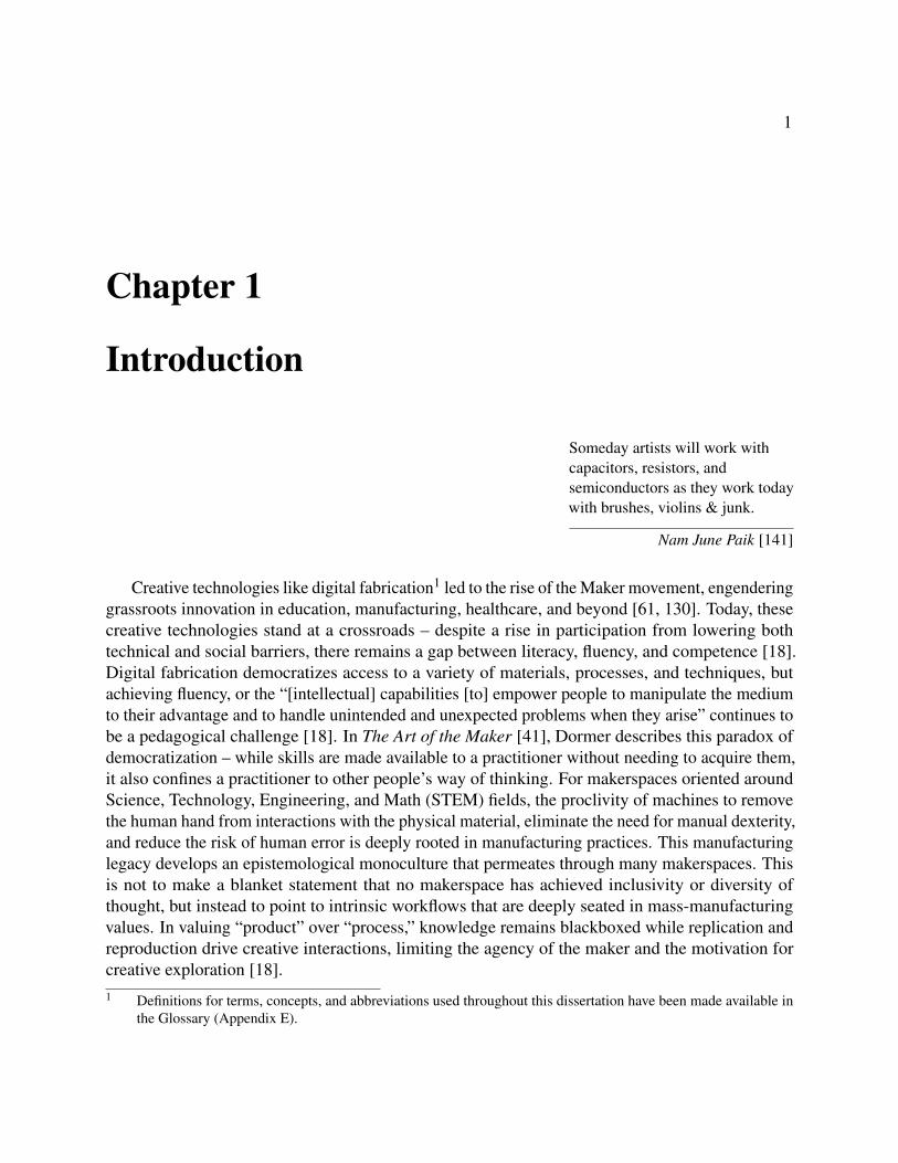
Figure 1.3: Forming Light: Crafting Proxies as an Immaterial Mediator
how light is used in both electronic practices and material practices. I then describe a composeabilitydesign stage, developing ways to expose additional creative inputs in what I term the material APIthat can be used to create forms that span the conversational profile. The result is luminaire designtool that decomposes the LED into computational design algorithms for creating Secondary OpticElements (SOEs), including lenses, reflectors, and diffusers. I demonstrate how this material APIcan enable new Illumination Aesthetics, including light textures, sharp and soft light edges, andnon-matrix light forms.
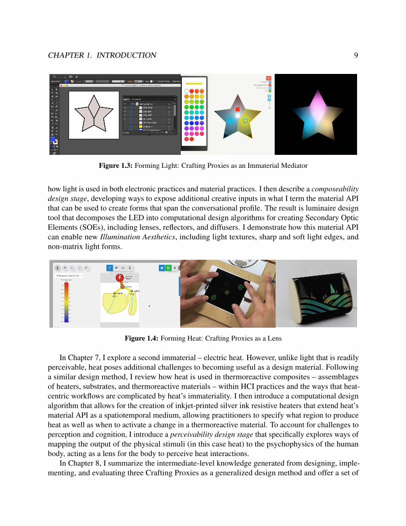
Figure 1.4: Forming Heat: Crafting Proxies as a Lens
In Chapter 7, I explore a second immaterial – electric heat. However, unlike light that is readilyperceivable, heat poses additional challenges to becoming useful as a design material. Followinga similar design method, I review how heat is used in thermoreactive composites – assemblagesof heaters, substrates, and thermoreactive materials – within HCI practices and the ways that heat-centric workflows are complicated by heat’s immateriality. I then introduce a computational designalgorithm that allows for the creation of inkjet-printed silver ink resistive heaters that extend heat’smaterial API as a spatiotemporal medium, allowing practitioners to specify what region to produceheat as well as when to activate a change in a thermoreactive material. To account for challenges toperception and cognition, I introduce a perceivability design stage that specifically explores ways ofmapping the output of the physical stimuli (in this case heat) to the psychophysics of the humanbody, acting as a lens for the body to perceive heat interactions.
In Chapter 8, I summarize the intermediate-level knowledge generated from designing, imple-menting, and evaluating three Crafting Proxies as a generalized design method and offer a set of

CHAPTER 1. INTRODUCTION 10
design principles for navigating the Crafting Proxy design space.
Figure 1.5: An SVG-based Computational Design Architecture
In Chapter 9, I review the current iteration of an evolving computational design architecturethat serves as the engine for many of the interactions, tools, and techniques used in this dissertationto implement Crafting Proxies. The architecture uses a common Scalable Vector Graphic (SVG)format and binds it with the paper.js SVG manipulation library, allowing SVGs to act as a commoninterface to additive and subtractive fabrication techniques, computational design algorithms, andIoT interactions and programming.
I conclude in Chapter 10 with a reflection of how research areas might develop to further supportmaterial epistemologies and make a case for a Hybrid Atelier, a creative environment designed tosupport hybrid making. I describe the potential for accessing embodied material knowledge throughmaterial parallels and developing input and output devices that engage more of the body in creativesensemaking. I also contemplate how transferring material knowledge might move beyond themaster-apprentice model and how lessons learned from our design investigations can inform a newgeneration of instructional resources that access and transfer tacit knowledge.
1.5 Statement of Multiple Authorship and Prior PublicationThis dissertation reflects work that was previously published in ACM SIGCHI (Illumination Aes-thetics [193]) and ACM DIS (ProxyPrint [191], Phosphenes [190]). Although I served as the firstauthor and led the research and writing behind each work, the ideas, concepts, and artifacts were aproduct of a group effort and benefited greatly from the wide breadth of knowledge and expertise ofthe interdisciplinary Hybrid Ecologies Group including Joanne Lo, Rundong Tian, Christie Dierk,Molly Nicholas, Sarah Sterman, Chris Meyers, and Kuan-Ju Wu.
The core concept of proxies was developed as part of an internship with Dr. Wilmot Li at AdobeSystems Research. Expanding the role of creativity support tools towards developing materialliteracy was formed during a collaboration with Joanne Lo and Dr. Mira Dontcheva. For IlluminationAesthetics, the fabrication procedure and computational design algorithm were developed jointlywith Niraj Rao, Ryan Kapur, and Jaqueline Garcia; the user study behind Illumination Aesthetics wasdeveloped and conducted with Molly Nicholas; central design artifacts were cocreated with JasperO’Leary (Tactile Cityscape), Viraj Rao (Illuminated Hair Brooch). For Phosphenes, fundamental

CHAPTER 1. INTRODUCTION 11
resistive heater characterizations were conducted and studied by Jessica Chang; thermowatercolorexperiments and artifacts were created by Advaita Patel (Phosphenes Buddha Mala); thermoreactivetextiles were created with Kuan-Ju Wu (Phosphenes Handbag).
My advisor, Professor Eric Paulos, provided key insights, critique, directions, and advice on allprojects detailed in this document.
In this document, I use the collective we when referring to the reader or describing technicalcontent. I use the first person when presenting concepts, arguments, evaluations, and discussions.

12
Chapter 2
A Profile of a Material Practice
The role of this chapter is to argue for the need of a unified description of a material practitioner’s“way of knowing,” or epistemology. For design tools in digital fabrication, a large focus is on helping“novices” in accessing digital fabrication tools; however, casting this target user group under thedichotomy of expert and novice fails to recognize the deep knowledge that material practitionerscould bring to digital fabrication practices.
The profile of a material practice I present here operates similar to a persona, a human-centereddesign method that constructs a fictitious description of a user group to help designers “understand,describe, focus and clarify user’s goals and behavior patterns” [28]. The profile is presentedusing concepts from Human-Computer Interaction and derived from ethnographies of creativepractitioners [172, 85, 175, 7], from a contextual inquiry of material practitioners conducted inpreviously published work [194], and from personal practice.
The profile breaks down a material epistemology into three areas: knowledge production,knowledge transfer, and knowledge application. I then describe opportunities for supportingmaterial practitioners within current state-of-the-art digital fabrication practices. This profile isthen used in subsequent chapters to both inform and assess the capacity of tools to support materialpractices.
2.1 IntroductionA material practice involves a practitioner working with materials, but this action is influenced by avariety of factors, from the practitioner’s background and expertise, the availability of tools andmaterials (and knowledge of how to use them), to the types of materials and artifacts that are valuedby a practitioner’s professional community, by their viewers, or by their customers.
In this profile, I organize these influential qualities centered on the material (e.g., clay asforgiving↔ economies of clay, availability of clay reclaimers, socially acceptability of error in apractice) as a way to distill a profile that can be used to contrast against non-traditional materials(e.g., hybrid materials, digital materials, smart materials, immaterials).

CHAPTER 2. A PROFILE OF A MATERIAL PRACTICE 13
What is a Material?Many definitions for what constitutes a material exist across a variety of disciplines. In HCI, theterm material is complicated by the fact that many materials can be computationally mediated, or berepresented virtually through techniques such as computer simulation or virtual reality, and mirrorthe ways one manipulates and interacts with physical materials in the real world. A growing trend inthe field is the election of a definition that is not predicated on notions of physicality [69]. Instead,a material is understood to be the physical, virtual, or conceptual elements that can be formed tocompose an artifact or experience. This definition allows for the term material to be contextual –a bell is composed of a bronze material, just as a bell tower is composed bell materials, just asthe sound bells produce is composed of different frequency materials. This definition additionallyallows virtual elements without physical qualities, such as computation, to be approached from amaterial perspective.
The Conversational Profile of Materials. In this work, I focus on the specific way in whichmaterials are used, where materials are not simply ingredients in a design that can be arbitrarilychanged but instead inform the design that is being created. Rosner [162] describes this influenceas the ordering capacity of materials, where non-human actors enable, influence, constrain, orcommand action. This quality of materials having an active role in influencing the final artifactor experience during the creative process reflects the core tenants of craft. Materials used in thismanner are referred to in this work as craft materials. Materials communicate in a variety of ways,proposing alternative courses of action or providing criteria for deciding which actions to take whenengaged in a creative process. I assemble these communicative mechanisms into a conversationalprofile (Table 2.1): sensorial feedback, affordances, and tradition. This conversation profile isused to formally describe how materials operate in a creative practice and how to better facilitate aconversation with materials.
What is the Role of Tools?Tools are central actors in creative processes but operate in the same capacity as craft materials. Wemight consider tools to be “tuned” or “well-designed” materials insofar as they communicate theirconversational profiles well and more readily influence the creative process.
Tools influence actions. A well-designed tool, especially those that have undergone iteration, willexpose available actions in its presentation. For example, in the case of a hammer, the affordance ofits weight distribution through its fulcrum communicates proprioceptively its ability to exert a largeforce. The role of affordance in communicating action has been widely understood in cognitivescience, where Maslow’s law of the instrument [122] formally captures the cognitive bias introducedfrom a familiar tool — a few moments with a hammer can quickly introduce a cognitive bias wheremany creative solutions are resolved by “treating everything as if it were a nail.”

CHAPTER 2. A PROFILE OF A MATERIAL PRACTICE 14
Communicative Mechanisms of a Material’s Conversational Profile
Sensorial Feedback Materials relay information via a set of physical cues that providesrich feedback about a material’s current state and potential future states. Materials highlysuited for craft engage many of the body’s senses, providing multimodal feedback throughtouch, taste, sight, sound, or smell. By engaging the full body in sensemaking, craftmaterials make use of a wider spectrum of cognition (e.g., embodied and spatial cognition).
Affordances Passive physical characteristics, or affordances, communicate available orpotential actions. A filament form-factor, for instance, communicates the material asextrudable. A flexible filament communicates the material as weavable.
Tradition (or Cultural History) Materials can communicate the intrinsic value placedupon them by a culture, practice, or group of people. Using barro negro, a black claybody found in the manganese dioxide-rich soil of Oaxaca, has a different symbolic valuein Oaxaca than elsewhere, just as how “preciousness” is ascribed to metals like gold orsilver. Value may change over time as practices evolve, such as in the use of discontinuedphotochemicals used in increasingly rarer analog photographic practices [7]. Value canalso transform from the mode of production. For instance, in response to mechanicalreproduction, Benjamin [15] uses the term aura to describe the qualities of an objectthat cannot be communicated through mass reproduction, signifying its originality orauthenticity. While two pieces of metal may be identical, the metal that is hand-craftedcarries the mark of the hand and communicates its uniqueness unlike that of a pristinemachine-formed metal.
Table 2.1: Components of a Material’s Conversational Profile
Tools access embodied knowledge. Tools, once learned, can elicit embodied cognition, or think-ing through bodily activity. Sennett [175] describes the role of primary consciousness, or the abilityto integrate observed events to create a sense of awareness, in the creative process. In the case ofthe hammer, the body acquires information in two ways: peripherally, through the haptic sensationof the hammer’s handle impressing on the palm of the hand, and focally, through the visual perceptof the hammer striking the nail. Although the haptic information is being perceived through thepalm, the information is synthesized into the awareness that the head of the hammer has struck thenail. This selective coupling of sensory information can be used to explain the phenomena of a toolexperienced as an “extension of the body” [126].
Tools support bricolage. An ecology of tools can aid with creativity. A bricolage practicedescribes an in situ “structuring of events through material assemblage and modification” restrictedto the “treasury” of tools, materials, and skills that are available at hand [200]. Designing tools to
CHAPTER 2. A PROFILE OF A MATERIAL PRACTICE 15
be plural, or reinterpretable past their designed function, can expand the repertoire available to thecreative practitioner.
Who is a Material Practitioner?Material practitioners are individuals that value, understand, acquire, and construct knowledge fromtheir interactions crafting materials. Material practices include woodworking, metalworking, leathercrafting, fiber arts, ceramics, painting, gardening, printmaking, drawing, cooking, and baking. Asugar worker, for example, must be highly conscious of changes in sensation, color, smell, texture,and reflectivity of sugar in the simple act of heating it. The logic of what to observe, how toasynchronously process multimodal stimuli, and how to make sense of how to manipulate sugar isdeveloped over time.
Material practice can also include digital media practices, including digital painting, video edit-ing, and certain types of programming. For instance, flow-based programming such as MAX/MSPor block-based programming such as Scratch provides a responsive and reactive environment forworking with computation as a craft material. Other programming practices such as codebendingtreat existing open-source programs as malleable, shapeable materials by “hacking” subcompo-nents and modules and reappropriating them as elements of a larger composition to achieve newfunctionalities and forms [16].
2.2 A Material EpistemologyEthnographies of material practitioners reveal essential distinctions in how knowledge is organizedand constructed, how process and the environment play an important role in inspiring creativeoutcomes, and the different goals that motivate engaging in a material practice. To better understandthe goals and behaviors of material practitioners, I synthesize these observations into three coreelements a material epistemology: how knowledge is produced, stored and retrieved, how thisknowledge is applied during a creative process, and ways in which knowledge is transferred anddeveloped by novice learners. A summary of a material epistemology is provided in Table 2.3 anddiscussed below.
Knowledge ProductionA metalworker develops an understanding of metal from working directly with the metal, i.e.,through a material encounter. By observing how metal responds to bending, forging, heating,and quenching, a metalworker develops a material mental model, or an internal representation ofa material’s properties and behaviors. The high dependence on observing a material’s physicalfeedback as it is manipulated forms an intimate relationship between a practitioner and material.Schön [173] describes this experiential way of knowing as thinking through doing, where knowledgeis generated from external actions that test, move, and probe stimuli that offer feedback to mentalmodels. These mental models guide the creative process and influence future behaviors and actions.

CHAPTER 2. A PROFILE OF A MATERIAL PRACTICE 16
1. Knowledge Production
Mental models are generated and reinforcedthrough material encounters.
1.1 Knowledge is generated from external actions that test, move,and probe stimuli, or thinking through doing, that offer feedbackto mental models.
1.2 Engaging with materials over time develops an intuition of ac-tion, i.e. wayfaring.
1.3 Failures are framed as part of the creative process.1.4 A collection of mental models of different materials form reper-
toires.
Tacit knowledge, versus explicit knowledge, isproduced.
1.4 Tacit knowledge is developed over time and internalized.1.5 Knowledge is stored subconsciously, e.g., through muscle mem-
ory.
Tacit knowledge can be externalized and ac-cessed through bricolage.
1.4 Artifacts act as a documentation of process.1.5 When made “available at hand,” artifacts support spatial cogni-
tion.1.6 Tangibile artifacts are shareable, supporting community reflec-
tion and critique.
2. Knowledge Transfer
Knowledge is transferred via the master-apprentice model.
2.1 Produces an uneven power structure.2.2 Places burden of understanding on the learner.2.3 Metaphors communicate tacit information.
Communities of Practice (COPs)s structurelearning environments.
2.1 Novices gain access through legitimate peripheral participation.2.2 Vertical learning structures support creating zones of proximal
development (ZPD).2.3 The community defines the critera for creativity from social
evaluation.
3. Knowledge Application
Knowledge is applied through the morpho-genetic (or form-generating) making.
3.1 Form generating versus matter forming.3.2 No correctness criteria; a form is evaluated as it emerges.
Practitioners engage in a conversation with ma-terials.
3.4 Materials have an influence on the forms that are generated.3.5 Materials are recognized as dynamic (e.g., leather develop a
patina).
Table 2.3: The Profile of a Material Epistemology

CHAPTER 2. A PROFILE OF A MATERIAL PRACTICE 17
Notably, failures in material practices are readily accepted elements of material practices, acting asa way of refining a material mental model or providing provenance through “happy accidents” [194,121]. Through practice, a collection of material mental models, techniques, and interactions arebuilt over time to form a repertoire that is applied to make sense of new situations [172].
Figure 2.1: (Left) A wall of a potter’s studio holds tens of firing keys that each record the results of a firingof a unique clay body and glaze combination. The potter externalizes their mental model of the firing processonto her environment, grabbing a set of keys when deciding how to glaze her latest work and guiding hercreative process. (Right) The keys each display a firing temperature and a patterned print used to mark andidentify finished pieces1.
In practice, some material practitioners adopt a bricolage practice whereby the creative process isinformed by the host of materials, tools, and skills available at hand [109]. In the case of the potter’sstudio (Figure 2.1), the potter externalizes her mental model of interactions between different claybodies (e.g., porcelain, stoneware, earthenware) with different glaze compositions and colors ontofiring keys — small samples that capture the results of the firing process. The keys serve both toguide her creative process and act as an artifact to communicate and transfer her firing experience toother guild members. These keys are available at hand which allows the potter to quickly compareand contrast different finishes, examine the texture and weight of different combinations, or conductfunctional tests (e.g., evaluating the water tightness of the clay body).
Material practitioners do not exclusively construct knowledge from material encounters, butbenefit as well from codified resources (e.g., books, videos, tutorials). However, the knowledgegained from material encounters produces tacit knowledge that often cannot be communicatedthrough traditional learning resources. Tacit knowledge, in contrast to explicit knowledge, is difficultto communicate through language often existing in the subconscious [152]. In practices such aswood carving, tacit knowledge can include:
• The amount of pressure to exert on the wood-carving tool.1 From contextual inquiry with Potter (11/7/2017) [194].

CHAPTER 2. A PROFILE OF A MATERIAL PRACTICE 18
• Processing the haptic feedback from the wood-tool interaction to determine if the blade issharp or dull.
• The rhythm, motion, position, and cadence of the arm, wrist, and fingers.
• The viewing direction of the head and the areas to observe.
• How different woods interact with carving tools.
• The planning of carving paths.
• How to adapt or recover from mistakes.
While some of this knowledge can be codified through video or metaphor, most tacit knowledge isstored in the body as part of a repertoire and is maintained through practice. The portability of thisknowledge to other domains is readily accessible — skills in wood carving, for example, readilytransfer to chocolate carving.
Knowledge TransferIn order to transfer tacit or embodied knowledge from one material practitioner to another, commontechniques employ multimedia instructional resources like images and video to capture and conveythis information [212] but often form an incomplete simulation of a making process. For instance,an instructional video lacks haptic or other sensory feedback mechanisms or the interactivity of anin-person training session. Metaphors prove especially useful in these contexts such as in conveyingthe amount of force to secure a nut (e.g., Monkey-tight versus gorilla tight) or how much sauce toadd to a poulet à la d’Albufera (e.g., “Put on his jewels”) [175]; however, these metaphors onlycapture a small subset of the tacit information produced. Other strategies include introducing a talkout loud during a training session to unveil the cognitive process of the maker (i.e., where to look,how they interpret stimuli, how they decide actions) [20].
Pedagogical structures in material practices are instead firmly rooted in the master-apprenticemodel, a vertical social learning structure that scaffolds knowledge and instruction through interac-tions between a skilled and unskilled practitioner. The explicit levels of expertise more rigorouslydefine zones of proximal development, referring to the difference between the task a learner canperform independently versus with guidance [202]. The zone refers to a sweet spot – if the task istoo easy or too hard, it prevents learning from occurring. The master-apprentice has the benefitsof behaviorist pedagogical strategies, introducing feedback mechanisms that ensure good habitsdevelop, skill progresses, and practice endures.
However, the master-apprentice relationship is a highly uneven power dynamic, and for prac-tices, such as STEM fields with social inequities [57], the hierarchical structure maintains powerand control within expert practitioners. More horizontal structures have been proposed utilizingcommunities of practices [74] that distributes the learning resources a student has available. Forexample, the availability of more-skilled peers supports any member of the community to reach theirzones of proximal development, while the increased visibility and status within the community act

CHAPTER 2. A PROFILE OF A MATERIAL PRACTICE 19
as motivators and rewards to sustain practice, develop skills, or lend expertise, allowing a newcomerto enter through the periphery and move towards the center of community in a process known aslegitimate peripheral participation [107, 48].
Despite these established learning structures, pedagogy still suffers from the expert blind spot,or the inability for the master to recall what it was like not to know [175]. For physical skills, thetype of learning interaction in a master-apprentice model devolves to observing the “correct” wayto manipulate a material. This places the burden of instruction on the student — the student mustresolve how their actions do not match that of the more skilled practitioner. Design methods in HCIhave explored ways of capturing tacit crafting information through ethnographic apprenticeship,placing an expert learner, i.e., a person with domain knowledge, to document their mental modelsthroughout the learning session [214, 162]
Knowledge Application - WorkflowsOver time, a material practitioner constructs an extensive repertoire of material mental models thataid in guiding actions and informing decisions during the creative process. Ingold distinguishestwo models of making – hylomorphic (or matter-forming) making and morphogenetic (or form-generating) making – that allow us to more formally distinguish qualities of a material epistemology.
Commonly observed in engineering and scientific practices, hylomorphic making, from theGreek hyle, “matter”; morphe, “form,” describes a making process where design is largely a cerebralactivity [85] (Figure 2.3). The process involves taking an imagined form and manifesting it asa sketch, schematic, or model. This form is then imposed on some matter until the final artifactresembles or behaves as imagined. An element of correctness and error follows this form of making,where success arises when the target design is achieved and failure when it does not. A hylomorphicworkflow also encourages an object-bias, the quality in which materials are seen as uniform actorsas opposed to dynamic forms (e.g., decomposing, oxidizing) [162].
Although the hylomorphic making is commonly observed in engineering and scientific practices,the pattern is also encountered in material practices. For example, in a stained glass practice (Figure2.2), a cartoon represents a 1:1 scale depiction of glass forms and colors. The cartoon is used toform a pattern that acts as a guide to cut and grind glass to match the target geometries. The finalpieces are assembled and soldered or caned together to form the final composition [63]. In thisregard, the arrangement, geometries, and color composition were composed under a hylomorphicmodel of making. However, a different mode of making arises from elements not fully-specified inthe cartoon. For instance, a glassworker still has the choice of which part of a pane of glass to cutfrom. A material encounter occurs in deciding how the unique imperfections, textures, or artifactsof each pane of glass will emerge in the composition and how the different patterns will interactwith each other.
The physical act of cutting and soldering the glass introduces an element of risk and consequently,skill. In this act, a glassworker develops a familiarity with geometries that are difficult or impossibleto cut (inner curves), glass that fragment in unexpected ways (textured glass versus smooth glass),or pattern combinations that form difficult to solder gaps (small geometries). Pye [155] describesthis quality of an artifact in danger or uncertainty during the making process as the workmanship

CHAPTER 2. A PROFILE OF A MATERIAL PRACTICE 20
Figure 2.2: A Stained Glass Process. A glassworker cuts and grinds geometries from a pane of glass materialwhich is often risky and error-prone. The glass geometries are lined with copper tape and soldered together.The skill of applying heat at the correct location, rate, and duration is tacit and developed experientially overtime. The different resistances found in each material for forming processes introduced a value system. Forglass, cutting textured glass results in more compositions that display a mastery of the medium than thosewith smooth glass2.
of risk which forms an integral component of crafting in that it forces a reflective process — apractitioner must be mindful of the material, its properties and behaviors, and its conversationalprofile. The effort and difficulty of working with materials introduce a value system that informsthe actions the practitioner will take.
Ingold describes this way of creating as following the morphogenetic model of making. Underthis model, the design occurs during the act of making. Materials have a more active role, signalingto the maker potential deviations and alternatives. Ingold uses the term wayfaring to describean “intuition of action,” where practitioners use past experiences (recover from errors, mistakes,and failures) to sense actions of resistance or opportunity and navigate the possible forms ofa material [85]. Design is never a straight path from low fidelity to high-fidelity but involvesexplorations in different directions to gain an experiential understanding of material potentials. Thisskill, more importantly, develops resilience to adversity in the making process, integral to sustaininga practice, since it reframes errors and failures as important learning moments. This value systemconsequently introduces elements of craftsmanship, or the ability to develop skill in a practice,that in turn influence how designs are chosen and the evaluation criteria of a practice. To otherglassworkers, a composition with rough-textured glass and small geometries with sharp inner curvesdemonstrates a mastery of the glass medium within a stained glass practice.
The morphogenetic model of making is a form of reflective practice, a process in which one2 Image credits [left to right]: Oceanside White on Clear Baroque Glass by Oceanside (BR/308-F) www.franklin
artglass.com; 3D Benchy by CreateItReal from https://www.createitreal.com/2017/01/16/highspeedbenchy/, How to: Stained Glass by Sarah James from Instructables https://www.instructables.com/id/How-To-Stained-Glass/

CHAPTER 2. A PROFILE OF A MATERIAL PRACTICE 21
reflects on actions, not dependent on established theory or technique, but constructs a new theory ofthe unique situation. These reflections include but are not limited to: what motivated or influencedthe course of action, how the problem has been framed, and the role within a broader socioculturalor institutional context. Schon [173] relates a reflective conversation with materials as a “designsituation where a practitioner constructs objects and relations using the active sensory feedbackof materials” [173]. The incremental development and reflection cycle whereby materials “talkback” to the creative practitioner throughout a creative session direct the creative energies of thepractitioner and shape how an artifact is formed.
2.3 Tensions of a Material Practice and Digital FabricationBoth hylomorphic and morphogenetic ways of making are part of any creative practice and are notrepresentative of an individual— an engineer may engage in a material practice and a metalworkerin a scientific practice — but it represents two distinct ways of knowing and, by extension, making.In this section, I will argue that the morphogenetic qualities are less visible within digital fabricationpractices and examine how other qualities of a material epistemology are difficult to realize withincurrent digital fabrication practices.
Tensions in Knowledge ProductionComplications of Immaterials. The ability to be formed is a distinguishing property of material-hood, but many materials in digital fabrication processes and spaces are challenging to see ormanipulate during the making process.
Immaterials are a class of materials that cannot be experientially manipulated or con-verted into an artifact or experience. Electricity, for example, is a physical phenomenon;however, the presence of electricity in electronics is invisible. Without transducersto convert electricity into light, heat, or motion, electricity “as a material” cannot berealized. Lyotard [119] theorizes immaterials as being imperceivable with respect tothe human perceptual system and uncomposeable, already forming the elementary partsof a system (e.g., atoms, ribosomes, electromagnetic waves).
Tensions of Digital, Physical, and Hybrid Materials. Other materials, such as hybrid materials,are formable through both digital and physical processes. For example, 3D printing allows a 3Dprint to have two materialities — a digital materiality gained from a digital mesh representation thatencoded its form and a physical materiality from the artifacts of the 3D printing process. Smartmaterials refer to more active materials that respond to or can be significantly be controlled byexternal stimuli. Liquid crystal, a thermochromic material that changes color with changes in heat,can be formulated to respond to specific temperature ranges and is a common material for makingpassive thermostats. Several tensions arise around using digital and physical materials in a makingprocess. Hybrid tools which facilitate this practice have gained traction in domains such as crafts by

CHAPTER 2. A PROFILE OF A MATERIAL PRACTICE 22
Figure 2.3: (top) Hylomorphic making in a stained glass practice – a cartoon is used to plan a composition,and glass it cut to match the design until the design matches the cartoon. (bottom) Hylomorphic makingin Fused Deposition Modeling (FDM) 3D printing – an abstract form is imagined and specified as an STLmodel; the resulting form is imposed upon a host of different materials in a filament form factor; the form isconsidered complete when it matches the target model3.
outsourcing tedious labor to machines [29] or leveraging the machine as a collaborator, helper, orgenerative constraint [40]. However, tensions result from ambiguities between materials: physicalprocesses are slow and near-at-hand; digital processes are inherently faster and are not limited bycolocation [88, 137]. Other tensions between digital fabrication and handed fabrication arise fromsociocultural practices such as:
• deskilling the artist by making the craft easier;
• masking the “hand of the artist,” or the distinction that an artifact is hand-made versusmachine-fabricated,
• dishonoring the material, such as tacking on other media like electronics [137], and
• failing to listen to the material, such as when a wood knot is not “heard” by a CNC machinewhereas a woodworker would detect it and alter the design [29].

CHAPTER 2. A PROFILE OF A MATERIAL PRACTICE 23
Tensions in Knowledge ApplicationThe de facto digital fabrication workflow for forming artifacts separates design and machiningconcerns, emulating product manufacturing relationships. As a commonly agreed-upon processworkflow, it allows for a single common design file to be used by several different types of ComputerNumerical Control (CNC) machines.
Figure 2.4: The traditional CAD-CAM workflow. In the computer-aided design phase, a computationalmodel is constructed using a modeling tool and typically exported as a watertight mesh (STL) or as curves(SVG). In the computer-aided manufacturing phase, the encoding is converted into a machine-interpretablegeometry, a tool-path is then planned to satisfy that geometry, and the compiled set of instructions is thencommunicated to a computer numerical control tool. The CAM process is device-specific and needs to be runfor each CNC tool.
The Computer-Aided Design (CAD) phase involves using a modeling tool to create a digitalrepresentation of an object which is then typically exported as a watertight mesh (STL) or as avector graphic (SVG). Because of the portability of the design file, i.e., accepted by many typesof CNC machines, the form may be realized in any number of materials such as plastics, resins,clays, or metals. In addition, the time-consuming printing process often means that the print is leftunobserved. The Computer-Aided Manufacturing (CAM) phase involves converting the digital3 Image credits [left to right]: (top) How to: Stained Glass by Sarah James from Instructables https://www.in
structables.com/id/How-To-Stained-Glass/; (bottom) Tugboat from https://all3dp.com; 3D Benchy byCreateItReal from https://www.createitreal.com/2017/01/16/highspeedbenchy/
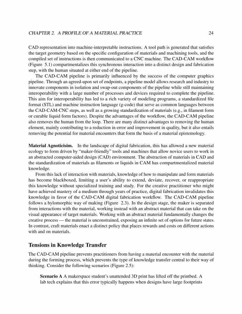
CHAPTER 2. A PROFILE OF A MATERIAL PRACTICE 24
CAD representation into machine-interpretable instructions. A tool path is generated that satisfiesthe target geometry based on the specific configuration of materials and machining tools, and thecompiled set of instructions is then communicated to a CNC machine. The CAD-CAM workflow(Figure 5.1) compartmentalizes this synchronous interaction into a distinct design and fabricationstep, with the human situated at either end of the pipeline.
The CAD-CAM pipeline is primarily influenced by the success of the computer graphicspipeline. Through an agreed-upon set of endpoints, a pipeline model allows research and industry toinnovate components in isolation and swap-out components of the pipeline while still maintaininginteroperability with a large number of processes and devices required to complete the pipeline.This aim for interoperability has led to a rich variety of modeling programs, a standardized fileformat (STL) and machine instruction language (g-code) that serve as common languages betweenthe CAD-CAM-CNC steps, as well as a growing standardization of materials (e.g., in filament formor curable liquid form factors). Despite the advantages of the workflow, the CAD-CAM pipelinealso removes the human from the loop. There are many distinct advantages to removing the humanelement, mainly contributing to a reduction in error and improvement in quality, but it also entailsremoving the potential for material encounters that form the basis of a material epistemology.
Material Agnoticisim. In the landscape of digital fabrication, this has allowed a new materialecology to form driven by “maker-friendly” tools and machines that allow novice users to work inan abstracted computer-aided design (CAD) environment. The abstraction of materials in CAD andthe standardization of materials as filaments or liquids in CAM has compartmentalized materialknowledge.
From this lack of interaction with materials, knowledge of how to manipulate and form materialshas become blackboxed, limiting a user’s ability to extend, deviate, recover, or reappropriatethis knowledge without specialized training and study. For the creative practitioner who mighthave achieved mastery of a medium through years of practice, digital fabrication invalidates thisknowledge in favor of the CAD-CAM digital fabrication workflow. The CAD-CAM pipelinefollows a hylomorphic way of making (Figure 2.3). In the design stage, the maker is separatedfrom interactions with the material, working instead with an abstract material that can take on thevisual appearance of target materials. Working with an abstract material fundamentally changes thecreative process — the material is unconstrained, exposing an infinite set of options for future states.In contrast, craft materials enact a distinct policy that places rewards and costs on different actionswith and on materials.
Tensions in Knowledge TransferThe CAD-CAM pipeline prevents practitioners from having a material encounter with the materialduring the forming process, which prevents the type of knowledge transfer central to their way ofthinking. Consider the following scenarios (Figure 2.5):
Scenario A A makerspace student’s unattended 3D print has lifted off the printbed. Alab tech explains that this error typically happens when designs have large footprints

CHAPTER 2. A PROFILE OF A MATERIAL PRACTICE 25
Figure 2.5: (Left) A 3D print has experienced lift-off, a printing error that occurs when thermoplasticcontracts and introduces internal stresses to the model. The common fix is to apply glue to the printingplatform for stronger adhesion to overcome forces from contraction. (Right) A clay vase is wrapped inmultiple different bags to control the drying rate of the clay. Drying too quickly can introduce internal stresseson the walls of the vase and cause fractures. The plastic bags are progressively removed, exposing thinner,faster-drying geometries first4.
and instruct the student to thoroughly clean the printbed, apply an adhesive, and reprint.
Scenario B A ceramicist’s vase has cracked. The ceramicist, having formed the claywith her hands, is acutely aware of how the material reacts to losing moisture. Sheobserves that the crack occurs between the thicker body and the thinner lip of the vase.The clay in the lip had dried much more quickly than the clay in the body, contractingand fracturing at the boundary. A fellow ceramicist advises her peer to cover the lip inplastic so that it dries at a rate similar to the body.
Both scenarios feature similar problems with internal stresses caused by materials contractingduring the fabrication process. However, the type of interaction and learning that occurs differs insignificant ways:
1. The ceramicist has a more embodied understanding of what is happening with the clay, havingfelt the clay dry and contract in her hands while forming it; the student must rely on externalresources to diagnose the issue (lift-off from internal stress caused by cooling plastic),
2. The fix is more causable, reinforced by what the ceramicist sees, feels, and smells; the studentengages in a “hack” that circumvents the problem,
4 Image credits [left to right]: STAMPA 3D Store from https://www.stampa3dstore.com/stampa-3d-come-evitare-le-deformazioni-degli-oggetti/; Ultimaker 2 Manual from https://ultimaker.com/; Contextualinquiry with Potter (11/7/2017) [194].

CHAPTER 2. A PROFILE OF A MATERIAL PRACTICE 26
3. If a problem surrounding internal stresses (cracks/warps) occur again in new contexts, theceramicist has in their repertoire an understanding of how to diagnose unwanted materialbehavior and troubleshoot; for the student, the thermodynamics of plastic remain blackboxed.
Domain Transfer. Compared to the domain transfer that a woodcarver can benefit from in stone,chocolate, ice, soap, wax, or fruit carving, these skills do not transfer to CNC tools that alsoutilize subtractive methods. In order to work with a CNC machine or a CAD program, a materialpractitioner must learn an entirely new way of thinking (e.g.,computational thinking) which displacesthe years of practice and skill they have developed. For instance, CAD programs oriented towardsnovices like TinkerCAD [8] use Constructive Solid Geometries (CSGs)s to provide an elementaryvocabulary of forms and operations (e.g., unite, subtract). This way of making 3D forms readilytransfers to additive and subtractive sculpture practices, but does not support the wider repertoire ofceramic 3D forming techniques like coil, slab, or slip-casting methods. This tension echoes callsto support thick practice, allowing for the continuity of practice and supporting skills that havebeen acquired over time by using common physical interfaces as opposed to digitally mediatingthem [103].
Furthermore, an element of facilitating domain transfer involves finding instructional resources.When building on uneven skillsets (i.e., across disciplines), the ability for material practitioners tofind an instructor or a peer to serve as one remains a challenge [184].
2.4 Definitions and ConceptsFor reference, the terms, concepts, and abbreviations used throughout the dissertation are availableas a Glossary (Appendix E).
2.5 SummaryMaterial practitioners are individuals that value, understand, acquire, and construct knowledge fromtheir interactions with materials, or material encounter. These interactions drive the developmentand refinement of material mental model that over time are collected into repertoires.
In a material practice, materials have an active role in the making process, influencing the typeof design, artifact, or experience that is created. Materials communicate alternative courses ofaction, which I term its conversational profile (Table 2.1) from sensory feedback, affordances, orfrom how they are traditionally used or the value they are intrinsically given by a group of people.
Depicted in Figure 2.3, the profile of a material practice summarizes how practitioners produceknowledge through material encounters, engage in morphogenetic making, develop an intuition ofaction known as wayfaring, and transfer tacit knowledge under the master-apprentice model.
I describe opportunities to bridge digital fabrication and material practices, describing frictionsbetween the two practices including: working with immaterials that do not offer sensorial feedbackor affordances, workflows that prevent material encounters from occurring, a lack of potential

CHAPTER 2. A PROFILE OF A MATERIAL PRACTICE 27
for domain transfer, and social and cultural barriers around access to training, supervision, andinstruction.
In subsequent chapters, I use this profile to inform the design of Crafting Proxies and assesstheir capacity to support a material epistemology. I apply this profile to develop a way for materialencounters to occur within a CAD-CAM pipeline and for mediating the conversational profile ofimmaterials to offer sensorial feedback to practitioners.

28
Chapter 3
Related Work
The first of many FabLabs was created in 2002 [203] despite the core technologies for the currentworkhorse of makerspaces – the 3D printer – being invented ten years prior [34]. These fabricationspaces served as small workshops with the goal of enabling everyone to make “almost anything.”This goal of democratizing digital fabrication and heralding in the next industrial revolution hasbeen a major area of interest of the Human-Computer Interaction community. Research aims toenable practitioners to create novel and inspiring solutions as well as broaden participation andenable communities to participate in creating their own technology [127].
Our work builds on these initiatives, contributing to two core research areas centered arounddeveloping creativity in digital-physical, or hybrid, making. The first body of work is known asCreativity Support Tools (CSTs) and Design Tools research. I review work in this field that dealswith hybrid making, or situations that contain both virtual sites (e.g., digital design tool, abstractmaterials) and physical sites (e.g., fabrication, physical materials) of making, in contrast to otherstypes of tools in this area for supporting ideation, social creativity, or digital media.
The second body concerns different design strategies for negotiating hybridity, or design contextsthat deal with digital and physical actors. I focus on work that specifically looks at negotiating craftand technology (e.g., in computation, in electronics, in digital fabrication).
Lastly, I discuss core analytical frames for understanding materials and creative practice used inthis work.
3.1 Design Tools for Physical MakingCoined by Shneiderman in 1999 [178], the origins of creativity support tools have a dialecticalrelationship with productivity support tools, or tools aimed at improving efficiency and productiv-ity, toward instead supporting discovery and innovation [180]. Nakakoji et al. [136] offer threemetaphors to better describe the creative tasks that CSTs can support: enhancing performance (i.e.,running shoes), developing skills (i.e., dumbbells), and enabling new experiences (i.e., skis). CSTsare closely related to design tools, with the distinction that design tools facilitate more than justthe creative task but also the transcription of this task into a representation that is accessible by

CHAPTER 3. RELATED WORK 29
Figure 3.1: Translators: (left to right) translating sculpting actions [176]; translating markers [169]; translat-ing measurements [205].
computation or CNC tools. I draw upon CST and design tool research used in the context of physicalmaking and organize this space using the frame of the proxy. A proxy, as described in Chapter 4,refers to a material, tool, or machine that acts as an intermediary between a practitioner and material.I describe work that has explored the different capacities a proxy can serve in facilitating creativework.
TranslatorsMost commonly seen in 3D sculpting, several tools aim to translate physical action to a digitalrepresentation and vice-versa. For virtual 3D sculpting, Sheng et al. [176] demonstrated how aphysical prop could act as a proxy to a virtual model, serving as a reference to virtual geometrieswhile translating physical clay-like sculpting actions into digital deformations. This strategy servesas a powerful tool to assist novices in interfacing with 3D CAD. In Makers’ Mark [169], annotationstickers are placed on a physically sculpted form and when scanned are converted into mechanicaland electronic components; this workflow allows practitioners to create interactive objects. Suchtranslational strategies, especially in introducing slower physical interaction, have been shown toprovide experts with a more reflective workflow [145]. Two-way translation has been exploredin creating a bidirectional design and fabrication pipeline. The system ReForm [206] continuallysynchronizes a physical object and digital model, allowing practitioners to physically shape ordigitally manipulate a form. This type of proxy is often constrained in its translational abilities,typically failing to capture an unknown quality important to the physical making process. A moreusable configuration translates actions seamlessly between virtual and physical spaces, such asSPATA [205], an augmented caliper that transmits measurements in physical space or actuatesto measurements in virtual space, or FormFab [132], a thermoforming interface that translatesgestures into realtime plastic deformation, bridging the digital-physical gap through input-outputcoincidence. Matchsticks [188] demonstrated conceptual translation, matching high-level woodenjoinery design intent to a repertoire of joinery cuts and fabrication workflows.
MediatorsWhile most translation proxies focus on an established physical-to-digital goal, i.e., clay to virtualclay, the inverse problem poses an additional challenge. Abstract or conceptual elements, such as

CHAPTER 3. RELATED WORK 30
Figure 3.2: Mediators: (left to right) mediating code [159], mediating signal [154], mediating air flow [199],compositing smart materials [99].
computation, must be mediated, or designed to have a physical representation. Without a “groundtruth,” the goals of this translation are defined intrinsically by the translator. The manner in whichconceptual materials are mediated has a strong influence on how knowledge is produced, applied,and transferred. For a visual programming language like Scratch [159], programming mechanismslike control and iteration mechanisms are given a block-based form. The blocks enable directmanipulation gestures and are designed with uniquely shaped connective appendages acting asaffordances, communicating the possible compositions of blocks into full-featured programs. Flow-based programs, such as MAXMSP [154], a flow-based programming language for multimediaartists, leverage input/output blocks that can be used to compartmentalize program functions intoconceptual building blocks; this construction strategy manifests new programming practices likecodebending [16].
In Section 3.3, I expand on the ways that different disciplines approach negotiating materiality.
Monitors
Figure 3.3: Monitors: (left) monitoring carving actions [225], (right) monitoring cutting actions [218].
The development of physical computing sensing and actuation technologies allow proxies tofilter and monitor content in the creative environment. FreeD [225] is a digitally-guided milling toolinformed by a predefined 3D model that slows down a spindle’s speed or retracts the shaft whena practitioner approaches making an error. In the inverse direction (informed by sensing the realworld), Enchanted Scissors [218], a digitalized cutting device, prevents users from cutting unwanted

CHAPTER 3. RELATED WORK 31
areas of a substrate by using a capacitive touch circuit to sense when the scissors are not in contactwith a conductive trace; a servo motor then reposition a scissor’s arms to provide tangible feedback.
LensesLenses refer to proxies that remap, retarget, and increase the saliency of stimuli to make the stimulieasier to perceive or present an alternative viewpoint. DemoCut demonstrated semi-automatic videotutorial editing filters that condensed and annotated videos to be perceptually and cognitively easierto digest and support learning [32]. In physical applications, Sculpt by Numbers used projectedcues to provide visual feedback to users sculpting a 3D model [161]. In a mixed reality environment,Ludwig et al. demonstrated the use of projection mapping to produce in situ visual cues to facilitatethe operation of a 3D printer, communicate the printer’s status, and recover from errors.
Armatures
Figure 3.4: Armatures: (left to right) supporting weaving [223], supporting painting [14], supportingwearable modeling [56].
Armatures represent a type of proxy that alters the environment to support and passivelyinfluence certain types of physical actions and frame the type of forms that can be created. Insculpture, armatures are sacrificial support structure made of wire, newspaper wrapped in plasticwrap, or styrofoam. The shape of these armatures influences and supports the forms that arecreated (e.g., a face armature serving as the base structure for masks). In Hybrid Basketry [223],Zoran used 3D-printed structures to shape hand-woven patterns while maintaining engagementin a traditional craft practice. In faBrickation [131], Lego bricks were embedded into 3D prints,allowing parts to be easily connected, creatively recombined, and selectively iterated upon. In thedigital painting system Painting with Bob [14], image-specific paintbrush textures supported novicepainters in developing agency in digital art creation. These brushes provided a fail-safe in ensuringthe creation of an intended form while maintaining freedom in how brushstrokes were applied. InTactum [56], using the human skin as an armature influenced the creation of expressive, complex,and wearable-oriented 3D models.

CHAPTER 3. RELATED WORK 32
3.2 Satisficing a Craft-based PracticeIntegrating craft into technological workflows has been a common theme for tools for making. Ifirst review these strategies and their respective limitations.
What is Craft?While often conflated to mean a manipulation of the hand (i.e. hand-crafted), crafting more preciselyrefers to a specific material-forward method of making in which there is a direct encounter with thematerial, such that that the material has influence on the forms that are being generated during theact of making (i.e., craft-based practice) [138, 85]. In hybrid crafting, where computing and craftmeet, Nitsche & Weisling [138] further distinguish that for crafting to occur, computation shouldrefrain from mediating the materials or actions.
The different variants and orientations of craft-based inquiry that have emerged in HCI aredefined by a careful integration of craft with digital and physical materials, the production ofresearch products, and the creation of deep and embodied knowledge from ethnographic inquiryduring the crafting practice [51]. I review some key approaches for integrating craft and technologybelow.
Intersecting Craft and ComputationEarly work in hybrid making proposed an alternative epistemology of the computational crafter –although the crafter worked with computation, the act of integrating computation into craft materialswould cause a re-examination of notions of computation (e.g., programming languages, computerarchitectures) [17], broadening what it means to engage in computational thinking. Golsteijn etal. [66] proposed that engaging in a crafting practice could function as a way to embed qualities ofpersonal expression into digital media artifacts. Tsaknaki [195] further develops this notion throughthe concept of “making preciousness,” tying both cultural and material experiences through craftinto interaction design.
Figure 3.5: (left) Lilypad Arduino [23]; (center) Chibitronics [156]; (right) E-textiles tester [153]

CHAPTER 3. RELATED WORK 33
Intersecting Craft and ElectronicsPerhaps the most successful of these endeavors is the Lilypad Arduino [23], an electronics con-struction kit that facilitated working with electronics and textiles. The kit defamiliarized the sitesin which electronics are typically found, altered the artifacts that are researched and produced,and transformed the demographics of people who engage in electronics practices. The Lilypaddemonstrated a strategy for broadening participation by Building New Clubhouses, or constructingand sparking new cultures versus trying to fit people into existing engineering cultures, evidencedby a female-dominated electrical engineering and computer science community continuing toemerge from the Lilypad [24]. Yet, despite this promising new subculture, e-textiles are a relativelynascent practice producing artifacts that fail to wed textile and electronics spheres of knowledge.For instance, leveraging traditional sewing and fiber art practices, e-textiles were used to exploreethnocomputing, or the study of interactions between culture and computing. E-textile workshopswere used to diversify the contexts in which an American Indian indigenous communities exploredcomputation, but in an open-ended design context, the integration of computation and indigenousknowledge were still viewed by students as two distinct bodies of knowledge [94].
Research is exploring how to more tightly integrate craft and electronics. A broader range ofcraft materials are being accessed through circuit stickers [157], through electronic componentsmade from textiles [148], through tools that give circuit-creation access to the hand (e.g., silverink pens, graphite pens, conductive thread), and through a more holistic integration with practices(e.g., via continuity-testing measuring tape, or electronic sewing pin probes [153]). This expandingrepertoire and deeper practice has led to an expanding wearable computing prototyping platformbut also indicates the potential for other material practices and computation to benefit from hybridmaking.
Intersecting Craft and Digital FabricationIntegrating craft and digital fabrication, the major research area of this dissertation, is an activearea of exploration. The consensus is that the combination of craft and digital fabrication is“incompatible”[95], produces inherent tensions [88], and goes against the grain [29] of crafting anddigital fabrication. To integrate the two, I describe some design approaches and their respectivelimitations.
One approach, most similar to our concept of proxies, theorizes a mediated middle groundthat allowed a practitioner to fluidly move from physical to digital space. Kamath [95] found thata craft (sense-evaluate-shape) ran counter to the idealized digital-physical workflow afforded bydigital fabrication. Kamath introduced a middle ground leveraging a digital scanner that allowedpractitioners to evaluate and shape a digital form, allowing a reflective practice to emerge. However,computationally-mediating a material presents several tensions with craft practices, formed inpart by some element of the real-world is neglected and the inability to access existing skills of apractice. Our approach positions this middle ground not in virtual space, but centered in the physicalenvironment to allow practitioners to use leverage skill sets and communities of practice.

CHAPTER 3. RELATED WORK 34
Alternatively, digital fabrication is situated as a collaborator or a facilitator of a crafting process.In the wild, Cheatle et al. [29] described how one wood-working studio practice had integrateddigital fabrication into their workflows, remediating traditional relations of craft. While CNC toolsand 3D scanning are used to outsource tedious labor and “grunt work,” they also enter into newmaterial-flows, giving a new creative capacity to the practitioner. However, how these CNC toolsare used go against the grain of the tool’s intention, a result of hacking and appropriation of themachine that relegates it to have the same relationship with the practitioner as that of a power toollike a chainsaw. While integrated with crafting workflows, the CNC tools are acknowledged as notcapable of listening to the materiality of wood, only capable of making precise cuts and carves onsome abstract surface. In the collaborative development of Arc, a CNC engraving tool for ceramics,within a clay studio, Rosner et al. [168] demonstrate four roles digital fabrication machines take inproducing forms: copying, replicating movements of the hand, translating, mediating other inputssuch as sound as form-giving elements, connecting, retaining evidence of new interactions withmachines and acting as an index to the collaboration.
A third approach transcends the boundaries of craft-based practices through developing a fluencywith digital materials or reifing the tradition-communicated elements of a digitally-fabricatedartifact. In Hybrid Reassemblage, Zoran merges digital fabrication and traditional craft throughthe destruction and careful reassembly of a ceramic vase with 3D printed parts, embedding historyand reclaiming the aura of a partially mechanically-reproduced object [224]. In Hybrid Basketry,Zoran [223] exposes a hybrid space in basket-weaving, created by leveraging 3D-printed wefts,arms, and lattices that allow for a basket-weaving practice to evolve. As a “physical manifestationof an intensifying desire to develop a new way of thinking,” Zoran demonstrates how attainingmaterial literacy in both domains can engender new practices and aesthetics, however, bound by theneed for others to join in hybrid making as a cultural practice. Supporting existing craft practicesthrough digital fabrication continues to find friction between digital and physical workflows. Jacobset al. [89] collaborated with the Namibian Ju/’hoansi people to explore how design and fabricationcould in integrated with traditional materials and practices of hunter-gatherer craft. While digitaldesign was found to find a role in this traditional crafting practice, digital abstractions conflictedwith the concrete design practices of the Ju/’hoansi and the workflows conflicted with the socialaspects of Ju/’hoansi making.
3.3 Analytical Frames for Understanding MaterialsDifferent approaches have been examined for understanding materiality and its role in creativepractice. In this section, I describe analytical methods for understanding materiality across Art, NewMedia, and HCI. The analytical methods are important for understanding how different disciplineshave approached the problem of working with elements that do not have tangible qualities and thepitfalls of focusing too deeply on physicality.

CHAPTER 3. RELATED WORK 35
Materiality in Art PracticeIn art practice, theoretical discussions of materiality were popularized in the 1950s by art historianClement Greensburg through the concept of material specificity [67]. The medium-specificity thesisstates “each art form should pursue those effect that, in virtue of its medium it alone — i.e., of allthe arts — can achieve.” which is often construed to mean “each art form should pursue ends that,in virtue of its medium, it achieves most effectively or best of all those effects at its disposal” [27].More simply, medium specificity states that a painting does not reach its full potential when itborrows forms from other media (e.g., a sculptural brushstroke). The painting fails the mediumin its hybridity. However, a large bias is introduced by the analyst in attempting to define whata medium’s properties are. Medium-specificity’s insular focus on maximizing the potential of amedium as opposed to situating the material (e.g., within a cultural moment) has since been rejectedin modern art discourse. However, medium-specificity continues to permeate in how materials areinterpreted by digitally-mediation tools [162] and how academic disciplines form [27]. In otherinstances, it is one of the strongest arguments for advocating for materiality as an emergent propertyor New Media [75].
Materiality in New MediaWithin New Media, the material is strongly tied to a medium that, by its nature, has a powerfuleffect on how we interpret experience. The Medium is the Message [126] refers to the idea that themedium, or the channel in which a message is transmitted, significantly transform how a messageis interpreted and in itself bear grounds for analysis. This was an analytical method developedby Marshal McLuhan in the 1960s during the times when the mediums of television, telephone,and print were under heavy public scrutiny. McLuhan ascribed that a medium is an extension ofthe body — each medium activates and attenuates unique sense ratios, or the different perceptualand information channels of the human body. For instance, cloth is considered an extension of thehuman skin. From this concept of sense ratios, he ontologically organized mediums based on thedegree in which senses are engaged, relegating low-definition media as cool media (e.g., telephone)and high-definition media as hot media (e.g., photographs).
While a McLuhanistic view of the medium is mainly an analytical frame, he does provide someindication of how this affects the production of artifacts. Media props describes the unique ways inwhich a medium (when compared to other mediums) changes the signal (i.e., message) that is beingconveyed. For example, a tune or melody in an NPR podcast between dialogues creates a feelingof place and narrative and is unique to the radio medium. Bodies on a stage acting out that samedialogue creates a feeling of presence, unique to theatre. However, both radio and theatre carrythe media prop of liveness. In the Ryerson Media Experiment [126, pg.483] found that, despiteconveying the same signal (a college lecture) across a variety of mediums (live, print, television,radio), the introduction of media props can transform the content and influence learning rates.
While similar to medium-specificity, media props advocate for an inspection of materials versususing it as criteria in which to evaluate the successfulness of a work.

CHAPTER 3. RELATED WORK 36
Materiality in HCIWithin HCI, , three views of materiality influence how digital materials are mediated in digital toolsand materials [70]: 1) the Tangible User Interface (TUI), 2) Metaphysical Materiality, and 3) Craft.In Tangible User Interfaces, the vision of Tangible Bits [87] and later Radical Atoms [86] extends therealm of mediation from a digital canvas to a physical and reactive context. By coupling bits (e.g.,digital operations, structures, and forms) with atoms (e.g., physical, graspable and reactive objects),computational materials are made physical. This approach, however, is constrained by the abilityto make transparent the mapping behaviors between computation and the physical object (e.g., amarble representing a voice recording) or developing a smart material. Under the metaphysicalviewpoint, computational composites [201] take a conceptual material like computation and defineits materiality through their interactions with other materials. These composites use a tightly-coupled physical proxy to remap behaviors, forms, and structures of computation as physical cues,acting as a representation of the conceptual material. Lastly, the crafting viewpoint describes aframing that leverages the communicative dimension of materials (e.g., the storytelling traditions ofknitting augmented with data markers like GPS locations [165]).
Leveraging materiality in interaction design has become even more relevant with digital toolsenacting influence on the physical environment. As new materials emerge within existing practices,Nitsche [137] observed the necessity of building on the material basis of the particular craft androoting interaction in the complex interplay of materials. While often associated with designingexperiential encounters within interaction design [62], more recently this material turn in HCI,i.e., the orientation for conducting interaction design research through a material lens [208], isbeing used to inform crafting (and material-driven design) practices with immaterials [9, 70]. Theexperience is characterized by materials having agency in the making process [187], taking on "amind of their own," resisting or cooperating with the attempts of the practitioner to form them in afashion is performative, resembling understanding, persuading, and responding to materials [53, 162,99]. Giaccardi and Karana [62] introduced a framework for articulating how materials participatein the making process, identifying four experiential levels: sensorial, interpretive, affective, andperformative. Schilling et al. [171] proposed discriminating the focus and attention of materialsactors over time as a method of characterizing the "talk-back" that occurs during a creative session.
Digital materials complicate a conversation with materials, lacking a rich sensorial interactionthat is central to a conversation with materials. Vallgårda and Redström [201] advocated for thenotion of computational elements as constituting many of the same characteristics as physicalmaterials such as substance, structure, and surface. Extending the concept of a computationalcomposite, Liu et al. [116] described smart materials having the ability to “[alter] a passive, staticconversation into an active, sensorial interaction.” In our work, I explore the generalizability of thiscompositing strategy to other immaterials, like computation, that share an intangible quality.

CHAPTER 3. RELATED WORK 37
3.4 SummaryUnlike their digital counterparts, hybrid tools do not attempt to fully simulate physical material or thephysical environment, allowing access to existing physical practices. Tools for hybrid making servea variety of capacities, from translating and mediating content, structuring the creative environment,or providing guidance and feedback to the practitioner but often suffer from fidelity.
Integrating craft into technological workflows has been a common theme for design tool research,especially for situations that invite physical making. Allowing for these tools to support a craft-basedpractice with computation has many benefits, including diversifying who participates in making, thekinds of artifacts that are studied and produced, and defamiliarizing the sites in which we encountercomputation. Although still disjoint, work in e-textiles and paper electronics indicate progresstowards a deeper integration of craft-based practice within electronics.
For endeavors to achieve a craft-based digital fabrication practice, the space is complicatedby the inherent differences between physical and digital materials. The ability to satisfy thesedifferences is highly dependent on the practitioner’s fluency with hybrid materials and their abilityto hack and reappropriate CNC tools. For digital fabrication, the largest challenge remains inestablishing a craft-based digital fabrication that is accessible to many, builds fluency, and accessesthe social qualities of a craft practice.
The work I present in this dissertation builds on this goal and contributes to the material turn inHCI, i.e., the orientation for conducting interaction design research through a material lens [208].Unlike prior work, I explore design tool research situated within a specific material practice. I’lldemonstrate how crafting proxies can be enacted within physical materials, physical tools, andphysical practices using computational design techniques to achieve a deeper integration with amaterial practice.

38
Chapter 4
Crafting Proxies
In this chapter, I introduce the concept of a Crafting Proxy as an intermediary between the practi-tioner and material. From the research literature, I construct a design space of proxies, delineatedesign concerns raised, and motivate the need to explore two key areas — physical armatures andimmaterial mediation. I then describe the Research through Design (RtD) methodology used tobuild intermediate-level knowledge to expand our understanding of methods to support materialpractices.
4.1 What is a Proxy?A proxy refers to an entity that acts as a substitute or representation for another. In its mosttraditional usage, a proxy is a person authorized to vote on behalf of another individual; in publichealth, infant mortality rates serve as a proxy to population health [158]; in computer science, aproxy server it is an intermediary between a user requesting a service from a third-party server.The proxy server offers important functions serving as an intermediary: providing security bymonitoring and filtering content, serving as an authentication authority [104], translating, caching,and compressing information exchanges [102], and its most subversive role acting as a way tobypass internet censorship [134].
In creative practices, I leverage the concept of a proxy to describe the relationship betweena practitioner and a material. A Crafting Proxy is a material, tool, or machine that is part of alarger network of a creative environment, which mediates interactions with a material facilitatinginterpretation, manipulation, and evaluation of emerging or potential forms as a part of a creativeprocess. Framing this relationship as a proxy foremost allows us to leverage a connotation to thenetwork and place creative action as a larger component of a sociotechnical system. It also actsas a way to situate creative activity outside a digital tool or physical tool dichotomy, colocatingthe virtual, physical, and even the biological on a common substrate. This colocation is similarto the effect of a proxy server transcending physical geographies (e.g., masking an IP addressto appear one is in another country). A proxy framing also serves in establishing interactions ascollaborations, reinforcing the “conversation with a material” basis of a material epistemology.
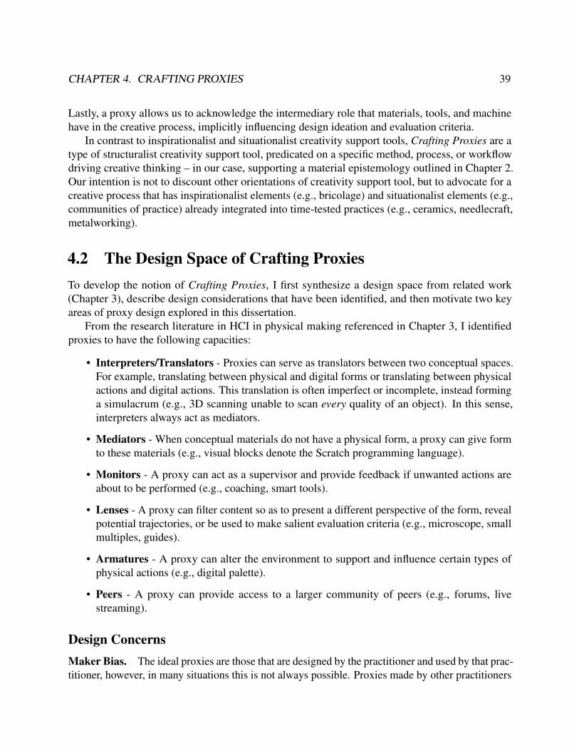
CHAPTER 4. CRAFTING PROXIES 39
Lastly, a proxy allows us to acknowledge the intermediary role that materials, tools, and machinehave in the creative process, implicitly influencing design ideation and evaluation criteria.
In contrast to inspirationalist and situationalist creativity support tools, Crafting Proxies are atype of structuralist creativity support tool, predicated on a specific method, process, or workflowdriving creative thinking – in our case, supporting a material epistemology outlined in Chapter 2.Our intention is not to discount other orientations of creativity support tool, but to advocate for acreative process that has inspirationalist elements (e.g., bricolage) and situationalist elements (e.g.,communities of practice) already integrated into time-tested practices (e.g., ceramics, needlecraft,metalworking).
4.2 The Design Space of Crafting ProxiesTo develop the notion of Crafting Proxies, I first synthesize a design space from related work(Chapter 3), describe design considerations that have been identified, and then motivate two keyareas of proxy design explored in this dissertation.
From the research literature in HCI in physical making referenced in Chapter 3, I identifiedproxies to have the following capacities:
• Interpreters/Translators - Proxies can serve as translators between two conceptual spaces.For example, translating between physical and digital forms or translating between physicalactions and digital actions. This translation is often imperfect or incomplete, instead forminga simulacrum (e.g., 3D scanning unable to scan every quality of an object). In this sense,interpreters always act as mediators.
• Mediators - When conceptual materials do not have a physical form, a proxy can give formto these materials (e.g., visual blocks denote the Scratch programming language).
• Monitors - A proxy can act as a supervisor and provide feedback if unwanted actions areabout to be performed (e.g., coaching, smart tools).
• Lenses - A proxy can filter content so as to present a different perspective of the form, revealpotential trajectories, or be used to make salient evaluation criteria (e.g., microscope, smallmultiples, guides).
• Armatures - A proxy can alter the environment to support and influence certain types ofphysical actions (e.g., digital palette).
• Peers - A proxy can provide access to a larger community of peers (e.g., forums, livestreaming).
Design ConcernsMaker Bias. The ideal proxies are those that are designed by the practitioner and used by that prac-titioner, however, in many situations this is not always possible. Proxies made by other practitioners

CHAPTER 4. CRAFTING PROXIES 40
and interaction designers will introduce bias into the creative process. Jennings and Giaccardi [91]advocated that navigating these biases should be guided by open-ended creative production andco-creation of tools with New Media practitioners within a “Research-in-Practice” approach. Open-ended, reconfigurable, and “hackable” tools have been shown to support reappropriation by creativecommunities, such as in the case of codebending [16].
Tool Influence. Proxies by definition influence creative process and “perform as materials,” re-sisting and accommodating to action [162]. As such, a proxy-mediated workflow should allow formultiple conversations to occur and not relegate a practitioner to a single design potential.
4.3 Expanding the Proxy Design SpaceIn this section, I motivate the relevance and extensibility of two proxy design areas investigated inthis dissertation and describe our methodology for synthesizing intermediate-level knowledge.
Physical ArmaturesA majority of creativity support tools have focused on digitally-mediating the creative process. Incontrast to proxies that act as monitors such as “smart tools” or “coaches,” armatures have thedistinct quality of being passive, introducing structural changes in the environment. The most simpleexample is the digital palette: a collection of swatches allows practitioners to leverage curatedcolors that align to aesthetics (e.g., Adobe Illustrator’s metallic color palette) or force practitionersto use a collection of colors because other actions are prohibitively expensive (e.g., Microsoft Paintswatches). Exposing additional control of color through hue-saturation-brightness (HSB) slidersintegrates color theory into available actions, making it easier to specify tints and shades of a color.However, it is less understood how such armatures function in hybrid environments where creativesites are digitally-mediated (on a computer) or physically-mediated (in the real world).
Like color theory instantiated as HSB sliders, what does it mean to communicate materialknowledge through a physical interface? How do different design decisions influence a practitioner’sactions? How might such armature proxies be incorporated into existing workflows that operate inhybrid environments? Understanding the design of physical armature proxies addresses Tenet 1:
Tenet 1 Material practitioners should be able to access and incorporate the years ofknowledge from their respective practices within digital fabrication workflows.
In eliciting bodily action, physical armatures allow for physical interactions that leverage therepertoire of tacit knowledge that exists in material practices. I investigate physical armaturesfurther in Chapter 5.

CHAPTER 4. CRAFTING PROXIES 41
Figure 4.1: Immaterials are elements that are difficult to perceive or manipulate by the human body unaided.
Immaterial mediatorFor abstract, intangible elements, or immaterials, such as computation, light, heat, electricity, orbiology, the ability to form a material conversation is complicated. For the creative practitioner, itbecomes trickier to work with such immaterial design elements as there are physical, chemical, andbiological processes that govern the underlying potentials and interactions, and these form invisibleand complex constraints that the designer needs to deal with. New media theory describes thelimitations of immaterials as being (1) inseparable, containing content that cannot be disassociatedfrom its structure (e.g., particles, waves, ribosomes), and (2) imperceivable and intangible, operatingat a scale that is no longer human-operational (e.g., genetics, biochemistry) [119].
Several approaches aim to visualize immaterials (e.g., visual programming, data visualization,material simulation); however, the focus on visual explanation limits the ability of materials to beused in physical practices. Vallgårda et al. argue that an immaterial like computation is a material,but in its raw form is difficult if not impossible to exploit [201]. Computational composites serveas one strategy for immaterials like computation to become useful in design. In a computationalcomposite, computation is bound to a physical proxy that remaps behaviors, forms, and structuresof computation as physical cues.
f : I !
Immaterial - ComputationIntensity Matrix from
Camera Sensor
Material - WoodOrientation ofWood Taxel
Material PixelExpressed from Tight Coupling
Figure 4.2: Daniel Rozin. Wooden Mirror (1999). 830 square pieces of wood, 830 servo motors, controlelectronics, video camera, wood frame. Size - W 67” x H 80” x D 10” (170cm , 203cm, 25cm).
For instance, Daniel Rozin’s Wooden Mirror (1999) (Figure 4.2) is an art installation composedof taxels, or small wooden squares arranged in a dense grid, each able to be actuated by stepper

CHAPTER 4. CRAFTING PROXIES 42
motors. When a bright light shines on the installation, each taxel reflects light or creates shadowsbased on its orientation. A small camera is mounted behind the grid of taxels, capturing the imageof the viewer experiencing the artwork. Rozin takes the digital intensity matrix from the camera’sCMOS sensor and uses it to control the orientation of each corresponded taxel in the woodenmatrix, thereby creating a mirror of the viewer. Wooden Mirror is an example of a computationalcomposites: an immaterial element, in this case, the digital intensity matrix from the camera sensoris mapped by some function to change the orientation of wooden taxels. Computation is tightlycoupled to wood “to come to expression as a material” and allow us to experience the abstractconcept of a pixel.
I see compositing as having the potential to address Tenet 2:
Tenet 2 Material practitioners should be able to use computation, electronics, andother emerging technologies like they would any other material. Such materialsshould be approachable and match their methods of producing, storing, applying,and transferring knowledge.
However, we understand less of the opportunities and challenges that arise when applyingthis compositing method to other immaterials. In our work, I explore the generalizability ofcomputational composites by applying the method to two other immaterials – light and heat.Through its ubiquity through the LED, compositing electric light allowed us to examine immaterialsthat have a long history in material practices and are readily perceivable. Unlike computation, light,or electricity, working with heat allowed us to examine immaterials that operate at different temporalscale and are more difficult to perceive. Generalizing the compositing method has the potential toinform how other immaterials, such as biomaterials and electromagnetism, can be leveraged bymaterial practitioners. I investigate immaterial mediators further Chapter 6 (light) and Chapter 7(heat).
4.4 MethodologyThis work employs a research methodology known as Research through Design where the act ofdesigning artifacts or prototypes (whether it be an object, system, or tool) is used to reflect andengage with theories, technologies, and models from various disciplines and operationalize how theycan be used in industry and by other practitioners. The act of designing produces new knowledge thatsits between abstract theory and concrete real-world artifact known as intermediate-level knowledge(c.f. [181, (43.3.4.)], [222]). This type of knowledge provides information around:
1. How to operationalize theory, models, and systems from other fields. The act of concretizingan abstract concept or integrating a model in a real-world setting can elucidate gaps in theoryor the conflicting frame of a model.

CHAPTER 4. CRAFTING PROXIES 43
2. How to make the artifact and understand the missing knowledge domains needed for under-standing the phenomenon under study.
3. Informing how future technologies should be made or the potential shift in experience anduse without needing to fully flesh out a system.
4. Generalizing design principles for navigating complex design problems.
Being able to articulate intermediate-level knowledge has evolved to reflect a host of differentdesign methods. These methods reflect a process for distilling theory, models, and knowledge fromother domains, methods of documenting and articulating design decisions as manifested during thedesign process or enacted in the final artifact, and a means of synthesizing intermediate knowledgethat is "contestable, defensible and substantive" [80]. Zimmerman et al. further describe evaluationcriteria around invention, relevance, and extensibility [222].
I develop intermediate level knowledge around two underexplored areas of the Crafting Proxydesign space — physical armatures and immaterial mediators. To describe process, I describea design method (presented in Section 8.1), developed iteratively throughout this dissertationthat provides an approach for satifying components of a material epistemology and proxy designconcerns. To document and articulate design decisions, I instantiate each core insight into a designartifact and annotate each work to form an anotated portfolio [58] (Section 5.8, 6.6, and 7.7). Lastly,to synthesize and substantiate proxy design principle, each design investigation is evaluated througha workshop study (Section 5.9, 7.8, and 7.8) inviting practitioners to create artifacts and reflect onthe experience of a proxy-mediated practice.
The next three chapters document our exploration of the Crafting Proxy design space. Theresults of these design investigations are synthesized in Chapter 8.

44
Chapter 5
Wire Forming
One can say that computers of allthings . . . are a means of makingavailable effects of other people’sskills to an individual without thatindividual having to acquire them.However, by acquiring no skills foroneself, then one is liable to betrapped by other people’s thinking.The unskilled individual cannotoverride the principles of themachine.
Peter Dormer [41], The Art of theMaker (1994)
In this chapter, I explore the capacity for Crafting Proxies to act as armatures. Armatures havethe distinct quality of being passive, introducing structural changes in the environment. Thesestructural changes facilitate a material encounter by acting as a support structure to encouragecreative engagement and exploration. While armatures readily facilitate digital interactions (e.g.,choosing a color from a digital palette), how material knowledge can be communicated throughphysical armatures is less understood.
At the core of the argument I present in this chapter, I make the case that physical armaturescan serve as a solution to the lack of material encounters within a CAD-CAM pipeline, and, inour proposed configuration, maintain the benefits of digital fabrication. I present an alternativeworkflow where instead of a digital fabrication process producing a final artifact, it generates aphysical armature – a computationally designed tool that aids the practitioner in making the artifact

CHAPTER 5. WIRE FORMING 45
themselves1 .To demonstrate our proxy-mediated workflow, we develop armatures for wire situated within
wire-wrapping jewelry practice. As a case study, wire-wrapping exemplifies a material epistemology;at the same time, Computer Numerical Control (CNC) machines have been specially designed forworking with wire [106]. This allows us to extend this pattern to other material practice – digitalfabrication crossovers and generate intermediate-level knowledge towards the larger design ofCrafting Proxies.
I first describe a conversational profile of wire, synthesizing the many ways wire communicatescourses of action during a creative process. I then document a computational design algorithmfor generating 2.5D models that function as wire-wrapping armatures and incorporate qualities ofwire’s conversational profile as physical affordances. I present an evaluation of three variants ofarmatures that provide different levels of assistance and document how each armature can supportdifferent qualities of a material epistemology in physical-digital workflows.
5.1 IntroductionWith the growth of digital fabrication practices, it has become possible to rapidly manufactureobjects in a growing range of materials, including plastics, ceramics, and metal, from a single digitaldesign representation. While the CAD-CAM pipeline lowers the barrier to entry and expands therange of materials that novice practitioners can work with, it also blackboxes the material knowledgeaway from the user preventing opportunities to reappropriate or deviate from the mode of production.Users are constrained to the available examples, templates, and methods of use prescribed by theauthors of the blackboxed knowledge (e.g., laser cutters used as keychain factories [18]).
In this chapter, I describe a Armature Proxy that reframes the CAD-CAM pipeline to produceintermediate tools, or proxies, that can be used to assist practitioners in forming an artifact. In doingso, a proxy-mediated practice reintegrates the human in the loop while eliciting morphogeneticworkflows. I operationalize the concept of a proxy-mediated workflow in the domain of wirewrapping, a popular metalworking medium that involves bending wire into aesthetic forms.
Why wire wrapping? Wire wrapping is a very popular form of metalworking and an idealcandidate for conversion into the CAD-CAM workflow. Metal wire already exists in a uniformductile form-factor that many CNC machine design patterns afford and can be modeled as a lesscomplex 1.5D material. Desktop CNC wire-benders are becoming widely available [146], howevertooling limitations restrict the scale and resolution of manufacturable wire forms.
Wire wrapping as a practice exhibits many of the characteristics of DIY communities: namely,there exists burgeoning grassroots innovation in tools and techniques; there exists a culture of sharedpractice through tutorials, workshops, and magazines; it is an extremely popular practice for both1 Elements of this chapter were previously published in: Cesar Torres, Wilmot Li, and Eric Paulos. “ProxyPrint:
Supporting Crafting Practice Through Physical Computational Proxies.” In: Proceedings of the 2016 ACMConference on Designing Interactive Systems. DIS ’16. Brisbane, QLD, Australia: ACM, 2016, pp. 158–169.DOI : 10.1145/2901790.2901828.

CHAPTER 5. WIRE FORMING 46
Figure 5.1: The CAD-CAM pipeline. Sketches or prototypes are converted into a computational representionusing a modeling tool. The tool then encodes this representation in a form that is accepted by CNC machines.This representation is translated into machine-specific instructions and sent to a CNC machine for fabrication.Many machines produce artifacts that require some post-processing.
professionals and hobbyists (> 320K hits on Etsy). It also is deeply embedded in 1.5D materialpractices such as needlecrafts, basket weaving, acrylic bending, and knot tying and draws froma bank of metalworking techniques including patination, polishing, forging, welding, soldering,coiling, and work-hardening. These elements are lost within the CAD/CAM workflow.
Although this work is specifically oriented around jewelry making, the wire form is ubiquitousin digital fabrication practices. Wire forms can act as fastener, heating elements, conductiveconnectors, and are seen in emerging materials like shape memory alloys. Wire is also a closerelative of thread form-factors. Thus, wire-wrapping represents an interesting and relevant contextin which to investigate how proxies affect DF processes for both novices and experts.
5.2 A Proxy-Mediated PracticeA proxy-mediated practice is a version of a CAD-CAM workflow that reintroduces the human inthe loop and reframes the goal of the workflow – instead of producing the final artifact as imaginedin the CAD tool, it instead produces a custom tool, or proxies, to assist a practitioner in making thefinal artifact. This workflow allows for material encounters to re-emerge but provides the advantages

CHAPTER 5. WIRE FORMING 47
Figure 5.2: Proxy-Mediated Practice. 1) A wire-wrap jewelry design is converted into a computationalrepresentation, 2) this representation is translated into an armature, or tool, that helps with making the targetdesign, 3) the armature allows for a material encounter to occur while still providing the benefits of digitalfabrication.
of automation and abstraction inherent to a digital fabrication practice.Armature proxies have the distinct quality of being passive, introducing structural changes
in the environment. In traditional sculpture, armatures support, frame, and influence the manualcreation process. By allowing users to work directly with a material, armatures facilitate a materialencounter, allowing tacit material knowledge to be generated and refine a user’s mental model of amaterial’s properties and behaviors. This process is iterative, combining the affordances of a digitaldesign file to refine designs and adhere to material constraints while also developing craftsmanshipand physical dexterity.
One important consideration in supporting a material epistemology is allowing forms to deviatefrom the original intention, i.e. engaging in a morphogenetic workflow. This work explores howproxies might assist users with challenging aspects of the fabrication task by providing morecustomized design-specific scaffolding that complements and build on a user’s existing skill set butdesigned to encourage deviation and creativity.
In wire-wrap jewelry, a proxy-mediated practice is realized through a 3D-printed shaping proxythat provides custom bending geometries to assist with shaping wire into target forms. I explore threevariants of a shaping proxy that offer different types of assistance to the practitioner — schematics,stencils, and jigs — and document how different design decisions can be implemented in proxies toencourage deviation, support morphogenetic workflows, and sustain practice.2 Image credits (left to right): Connie Fox at Jatayu from http://www.jatayu.com/Education/StudioTou
r/ST-WrappingJigs.htm; Barrel Nose Pliers from https://www.amazon.com/Step-Barrel-Plier-Pack/dp/B005FMZ8VY; Beadsmith Mandrel from https://picclick.co.uk/; Wire Wrapping Vise on Etsy fromhttps://www.etsy.com/uk/listing/242986933/wire-wrapping-jig-vise-fnt; Beadalon Deluxe Thing-A-Ma-Jig from https://www.dickblick.com/products/beadalon-deluxe-thing-a-ma-jig/; Board for WireWrapped Jewelry by elgolem at Thingiverse from https://www.thingiverse.com/thing:618600

CHAPTER 5. WIRE FORMING 48
Figure 5.3: Tools of the Trade. Pliers, jigs, mandrels, vises are commonly used in wire-wrapping and areoften custom-made for specific jewelry designs.2
5.3 Related WorkCreativity support tool research has explored methods of creating tools that enable more synergisticinteractions between maker and materials. Below, I describe work around digital and physicallyaugmented tools, instructional tools, and principles from traditional tools. Lastly, I describe workwork around metal and wire bending.
Augmented toolsDigitally augmented tools or smart tools combine some digital or computational intelligence withmanual usage, and primarily act in the service of providing higher accuracy or fidelity. FreeD, anaugmented substractive milling tool, provided feedback to users through autoshut off features. WhileFreeD provided support in adhering to a target 3D model design, it also provided a “human-overide”mode that allowed users to deviate from the digital model. Enchanted scissors used conductivetraces to detect and prevent incorrect cuts [218]. Peng et al. use common clay coiling techniquesas a way to additively construct and digitally scan geometries at fabrication-time, allowing formsconstructed during the making phase to be source material for a CAD design [145]. In HybridBasketry, Zoran explored how digital fabricated armatures can support and guide the basket-weavingprocess and influence the final artifact design [223]. Notably, the role of digital fabrication in HybridBasketry is not a driving or stopping force, but acts solely as a support structure. ProxyPrint buildson this idea of passive assistance and expands the set of computationally-generated support fixturesfor the wire-wrap medium. I use these features to further explore how different types of assistanceaffect the making process and experience.

CHAPTER 5. WIRE FORMING 49
Augmented practice and materialsAbstracting materials into primitive additive and subtractive processes, such as fusing sand into glass,can omit much of the rich cultural history of people working with a material (e.g. glass-blowing).Several works investigate how the cultural experience of tools, mediums, and their practice canenhance the making experience. Jenkins et al. explored the religious experiences that are associatedwith crafting practices and created devotional gardening tools mediated with electronic and digitalfeedback [90]. Rosner et al. explored the combination of clay and digital fabrication, describingthe tensions occurring from the displacement of the medium from the ceramist’s hand [164].ProxyPrint complements this previous work; I similarly design the experience of handed practicesinto our armatures to allow for material encounters and opportunities for tacit knowledge transfer tore-emerge in the CAD-CAM pipeline.
Design-specific fabrication instructionsSome existing design tools focus on domains that require manual fabrication of the final artifact,such as plush toys [83], inflatable balloons [54], planar cardboard sculptures [78], and customizedgarments [198]. The output of these tools is typically a set of instructions for how to make theuser-generated design. More implicit fine-grain instructions have been explored in systems likeSculpting by Numbers [161] which provides users with a “diff” between forms through a scanningand projection interface, non-intrusively aiding them in evaluating their progress.
Scaffolds on designSeveral systems study the impact of levels-of-assistance on user experience and design outcome.Painting with Bob, a design tool for digital painting evaluates a simple toolset (e.g. an eraser thaterases everything under the cursor) against a smart toolset (e.g. an eraser that erases similar colorregions under the cursor) [14]. PortraitSketch provides a set of automatic assistance algorithms foradjusting user strokes while drawing to achieve a certain portrait aesthetic [216]. I similarly studythe effects of level-of-assistance in the context of a physical material practice.
Wire design and fabricationSome existing commercial products help users create wire-wrapped artifacts. Companies likeWigJig and Beadsmith provide kits that allow users to create customized “jigs” by inserting differentsized cylindrical pegs into a board (Figure 5.3). However, the discrete set of peg sizes and positionslimits the designs that such kits can support. CNC wire benders such as DIWire have automated thewire bending process, with some tooling limitations. Such machines have been proposed as sites forinteraction: Willis et. al. Speaker interactively “sculpts” wire based on sound wave forms [209].Most relevant to the domain of our work is WrapIt [82], a computational design tool for convertingline drawings into optimal wire wrap forms (“wire decompositions”) that can be fabricated withthe help of a 3D-printed jig. I build on this work in several ways. First, while WrapIt focused

CHAPTER 5. WIRE FORMING 50
Figure 5.4: Comparison against WrapIt [82]
mainly on the design problem of converting line drawings into wire decompositions, I concentrateon the problem of fabricating a given design. Our wire shaping jig design offers some importantimprovements over the original WrapIt jig. I also investigate the question of level-of-assistance,which is critical for the design of physical tools that aid the creative process of manual fabrication.
5.4 Design ProcessTo explore the concept of a proxy-mediated practice, I first developed a computer-aided design toolthat would support common actions and motifs of a wire-wrapping practice. The tool provided anannotated design file that could be sent to and interpreted by a CNC wire-bending tool.
Our design intervention explored how we might reappropriate the design files in this and otherCAD-CAM based practices to transfer material knowledge and facilitate material encounters. Toaccomplish this, I first examined the wire-wrapping style. A style refers to the “constancy, orconsistency, in the way an individual, or a group, treats the formal elements of art, or visual culture”[69]. I explored the wire medium not only by its physical affordances or properties, but also throughthe expert practice and tradition that have already produced conventional uses, meanings, andtechniques with this material. By placing ourselves as the expert learner without previous wirewrapping experience, I distilled tacit knowledge from the material practice of working with metalwire.
I then developed a computational algorithm that integrates material knowledge of bending wireand planning bending action to generate a shaping proxy. This shaping proxy takes as input atarget wire form from the wire-wrap CAD tool and generates a 3D model of a tool that assists withforming a wire. I leveraged this algorithm to explore how proxies can provide varying amounts ofscaffolding for the user. To examine this aspect of the design space, I take the basic elements of our

CHAPTER 5. WIRE FORMING 51
Figure 5.5: ProxyPrint Computational Design Tool for Wire-Wrapping. ProxyPrint Computational DesignTool for Wire Wrapping. Users can drag common forms onto a canvas, manipulate paths, specify materials,and add ornamentation and connections. The tool produces a heightmap used to generate a 2.5D printableproxy.
wire shaping proxy and consider design variations that offer different types of assistance. I refer tothese variations as scaffold proxies. I use a workshop evaluation with 12 practitioners to evaluateand annotate these design artifacts and probe how different types of assistance can enhance andalter the creative process.
5.5 Wire-wrapping CAD ToolI developed a wire-wrap computer-aided design tool to use as a design probe. The probe wouldmirror the traditional CAD-CAM pipeline, creating a digital design file that would then be transferredto a CNC tool for manufacturing. However, this pipeline would use the digital design file to embedmaterial knowledge of the wire-wrapping practice into the design of the proxy tool. As opposed toa general-purpose 2D design tool, this tool incorporates the unique concerns of a practice, in thisway advocating for specialized tools that better encode a practice. The wire-wrap CAD tool wasthus designed to encode the necessary information needed to support this knowledge transfer andfacilitate a material encounter with wire.
The tool was developed as a web application using the Computational Design Architecturedescribed in Section 9. This web application syncs with a local SVG file to allow users to useexisting SVG editors to create initial geometries for their design. The design is then converted into a2.5D tactile model and 3D printed. Although the tool follows a direct manipulation interaction style

CHAPTER 5. WIRE FORMING 52
to simulate physical making, it is unavoidably not physical making. While wire-wrap practitionersmight initially sketch designs on paper or inspired by an existing design, a material encounterrequires active interaction with the physical material. I make progress in resolving this tensionthrough digital design mechanisms, specifically:
• A Library of Wire-Wrap Forms. Sourced from artisan handbooks [19], wire-wrap designprimitives were extracted and presented as importable forms on a digital canvas with actionsto reflect, duplicate, and arrange elements to form symmetrical and rhythmic compositions.Binding these actions to hotkeys allowed for epistemic interactions, allowing users to reflectand think through different form interactions.
• A Catalog of Gems, Beads, and Connectors. A collection of gems and beads and a vocabularyof common connectors (e.g., coils, jump rings, ear wires) were converted into 2D SVGrepresentations and collected into a wire wrap catalog. I manually captured the size andshape of each form; as an alternative, a 3D scanning process could more seamlessly allowpractitioners to capture materials and incorporate elements of their surroundings and supporta bricolage practice. The design tool exposed the catalog as a gallery of small multiples thatcould be drag-and-dropped onto the design canvas.
• Decomposition of Forms. A computational routine decomposed wire forms into hierarchicalprimitives. A heart shape, for example, was decomposed along its vertical symmetry. Thathalf-form was then isolated as a curve and sharp bend. In the proxy-design phase, I describehow this hierarchical form tree was used to generate proxies that allowed for deviationfrom the initial design so as to not restrict and finalize the final form of the design in thecomputational design phase.
• Material Specification and Visual Simulation A database of common craft wire materials(e.g., aluminum wire, bronze wire) was created to encode both visual appearance (e.g., colorand gauge) as well as physical properties (e.g., hardness). From the design tool interface,users could select SVG paths, assign a material, and impart these qualities onto the digitalrepresentation.
All of the wire wrap designs and primitives used in this work were sourced from artisanhandbooks [19] and community forums 3 and encoded as SVG drawings.
5.6 Material Practice with Metal WireWhile a finite element model (FEM) may be used to simulate the physics and interactions of wire,there is essential tacit knowledge that is not captured by scientific and engineering practices. In thissection, I describe some tacit elements of the wire-wrapping practice encountered from personalpractice in learning wire wrapping, similar to the role of an expert learner proposed by Wood et3 www.pinterest.com

CHAPTER 5. WIRE FORMING 53
al [213], learning from wire-wrapping workshops, formal instruction, video tutorials, and instructionmaterials while documenting how a wire-wrapping mental model developed.
Wire-wrap TraditionFormally, the wire-wrapping workflow is to first shape one or more wires into appropriate forms,then forge or work-harden wires so as to retain or enhance their form, and finally, connect separateelements to form a single coherent composition. These wire forms often serve a structural purpose,to secure beads and gems, or an aesthetic role, in constructing an experience. The workflow of awire-wrap practitioner is highly reflective and follows a material epistemology described in Chapter2. Metal wire resists or conforms to the actions of the wire wrapper; understanding how thesebehaviors change with each manipulation of the wire is an important yet tacit trait for masteringwire wrapping.
Choosing a Tool. Shaping a piece of wire into a desired form is the primary task in creatingwire-wrapped artifacts. In general, it is difficult to bend wire to create smooth curves that matchthe proportions of a design. Wrappers employ hand tools and custom-built jigs for this purpose,but using such tools effectively is challenging. For example, different types of pliers heads are bestsuited for different types of bends: flat-nose for sharp angles, barrel- or taper-nose for curves andswirls, and chain-nose for general bending.
Producing Complex Forms. For complex geometries, wire wrappers leverage jigs, a customarmature that provides support for forming a specific design. These jigs range from more permanentsolutions like nails screwed into a substrate of wood to more dynamic designs like pegboards.For designs with many identical components, wire wrappers employ a tool known as a mandrel,typically a cylindrical rod, that wire is wrapped around. A ring mandrel, for example, contains thegeometries of different ring sizes stacked on top of each other. Using a technique like coiling, awire is wrapped into a coil using a mandrel, removed from the mandrel, and then cut down theprimary axis resulting in multiple copies of the wrapped form. This coil-and-cut technique is usedfor batch-producing circular connectors, or jump rings, a wire is wrapped around a cylindricalmandrel; the coil is cut and the resulting geometries forged against an anvil to work-harden theform.
Dealing with Work HardeningA very practical material behavior is the spring back that occurs when a wire is bent. In abending action, wire is compressed alongside the inside of a bend and strained on the outside bendintroducing forces in compression and tension. Spring back is an artifact of work hardening, aplastic deformation caused by dislocation of a metal’s crystal structure. Wire is softening by heating(and reforming) the crystal structure. Wire can be hardened through cold-forming techniques suchas squeezing, bending, drawing, and shearing. The process of shaping the wire through bends or

CHAPTER 5. WIRE FORMING 54
hammering causes an increase of dislocations resulting in a work-hardened “rigid” wire. A wirewrapper develops a heightened awareness of a wire’s hard-soft state. It is the task of the wrapperto selectively harden wire in appropriate regions. This is desirable by metalworkers to a) increasethe structural integrity of the form to prevent deformation (e.g., curves), b) combine softness andrigidity to create new material behaviors (e.g., ear wires), c) add aesthetic variety (e.g., texture), ord) connect or secure beads and gems.
Minimizing Interactions. Wire wrappers take care in limiting and reducing interactions with thewire. The more work that is done on the wire, the more areas that have been hardened; a slip ofthe hand may cause an unwanted bend which would be more difficult to remove within hardenedareas of the design. Excessive work-hardening, such as that caused by bending a wire in the samespot multiple times, will cause the material to become brittle and prone to fracture. Experts planthe sequence of bends to minimize interference between the wire, pliers, and other tools as theymanipulate the material.
Material Undo. In practice, traditional craft wire is usually annealed, a process that realigns thecrystalline structure of the metal resulting in a more malleable “softened” wire and packaged ina spool in a softened state. Nylon pliers function to both compress and straighten the wire form,removing the imprint of the spool, and also harden the wire through friction so as to retain newbends more easily. The nylon wires also serve as a material “undo,” allowing accidental bends to beremoved.
Marring and an Ornament Fail Safe. Materials softer than metal, in the form of fingers, nylonpliers, rubber hammers, and rubber anvils, prevent the marring, or scarring, of the surface of a metal.When using metal tools, wire wrappers pay special attention to the forces exerted on the wire or usesacrificial elements to hold and anchor a wire. When marring occurs accidentally, wire wrappers“cover-up” the mistake with a coil, bead, or weaving ornamentation. Additionally, forging the metal,i.e., deforming the metal with a metal hammer and anvil, is used to regain an unblemished wire.
Manipulating WireWhen forming wire into a shape, different geometries require the wire be held to anchor the part ofthe wire that is being manipulated. Some geometries require the practitioner to exert stronger forcesmaking it more likely to accidentally deform unwanted areas of a wire. Wire-wrappers employ thefollowing anchoring techniques.
Sacrificial Ends. Many wire wrap designs end in loops, curls, or spirals. Manipulating the end ofa wire is particularly difficult, both with regards to exerting appropriate force and controlling thewire without distorting the design. Wire wrappers leverage excess material at each end to serve asmanipulation handles. Once the form has been achieved, the residual material is clipped away.

CHAPTER 5. WIRE FORMING 55
BEFORE OPENING CLOSING
AXIAL
LATE
RAL
work hardening
Figure 5.6: Wire-shaping strategies. Opening and closing a jump ring using (top) axial bends and (bottom)lateral bends. Note the deformations that arise from lateral work-hardening.
Axial Deformation. Wire wrappers recognize that the wire “has a mind of its own,” where springback prevents the wire from sitting flat on a plane. Instead, practitioners often construct their designsin 3 dimensions by deforming the design on its axial dimension (in line with the direction of thewire).
For instance, a jump ring is a circular geometry typically used to connect elements together(Figure 5.6). Two strategies exist for opening and closing jump rings to add or remove elements.
• A material naïve approach manipulates wire as a 2D element. In deforming the ring alongthe planar dimension, this bending action work hardens a subarea of the ring. When the jumpring is closed, this work hardening deforms the jump ring.
• A material-centric approach manipulates the wire along its axial dimension, acknowledgingthe three-dimensionality in the wire’s resistance to laying flat. The jump ring is still work-hardened. However, it is work hardening along the dimension orthogonal to the wire formthat prevents deformations to the ring while improving the ring’s resiliency to opening.
For more complex designs, axial deformations allow practitioners the ability to move finishedelements of a design away from the active forming area and securely anchor their design.
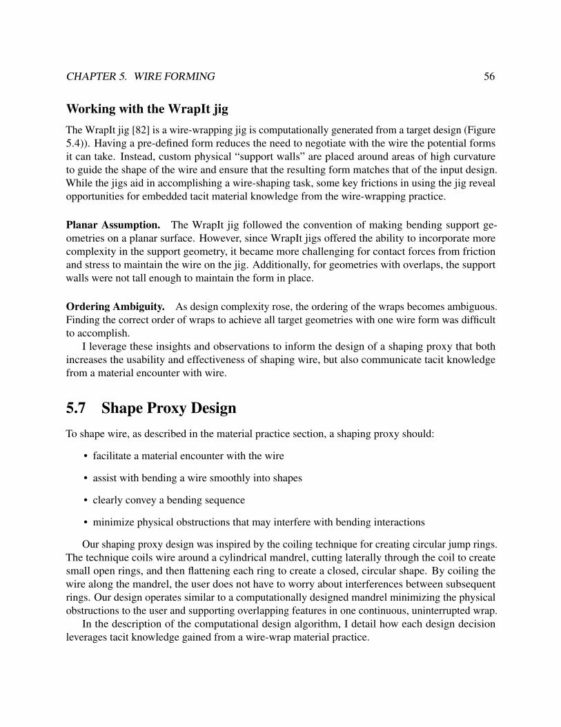
CHAPTER 5. WIRE FORMING 56
Working with the WrapIt jigThe WrapIt jig [82] is a wire-wrapping jig is computationally generated from a target design (Figure5.4)). Having a pre-defined form reduces the need to negotiate with the wire the potential formsit can take. Instead, custom physical “support walls” are placed around areas of high curvatureto guide the shape of the wire and ensure that the resulting form matches that of the input design.While the jigs aid in accomplishing a wire-shaping task, some key frictions in using the jig revealopportunities for embedded tacit material knowledge from the wire-wrapping practice.
Planar Assumption. The WrapIt jig followed the convention of making bending support ge-ometries on a planar surface. However, since WrapIt jigs offered the ability to incorporate morecomplexity in the support geometry, it became more challenging for contact forces from frictionand stress to maintain the wire on the jig. Additionally, for geometries with overlaps, the supportwalls were not tall enough to maintain the form in place.
Ordering Ambiguity. As design complexity rose, the ordering of the wraps becomes ambiguous.Finding the correct order of wraps to achieve all target geometries with one wire form was difficultto accomplish.
I leverage these insights and observations to inform the design of a shaping proxy that bothincreases the usability and effectiveness of shaping wire, but also communicate tacit knowledgefrom a material encounter with wire.
5.7 Shape Proxy DesignTo shape wire, as described in the material practice section, a shaping proxy should:
• facilitate a material encounter with the wire
• assist with bending a wire smoothly into shapes
• clearly convey a bending sequence
• minimize physical obstructions that may interfere with bending interactions
Our shaping proxy design was inspired by the coiling technique for creating circular jump rings.The technique coils wire around a cylindrical mandrel, cutting laterally through the coil to createsmall open rings, and then flattening each ring to create a closed, circular shape. By coiling thewire along the mandrel, the user does not have to worry about interferences between subsequentrings. Our design operates similar to a computationally designed mandrel minimizing the physicalobstructions to the user and supporting overlapping features in one continuous, uninterrupted wrap.
In the description of the computational design algorithm, I detail how each design decisionleverages tacit knowledge gained from a wire-wrap material practice.

CHAPTER 5. WIRE FORMING 57
Computational Design AlgorithmLeveraging the SVG to 2.5D geometry creation process described in Chapter 9, the algorithm takesin a single SVG path and produces a heightmap which is then converted into a 2.5D model forfabrication. The resulting 3D-printed shaping proxy contains bending geometries that sit atop arectangular base4.
The shaping proxy tool can then be used to shape wire as depicted in Figure 5.7:
Figure 5.7: How to Use a Shape Proxy
1. A smooth work-hardened wire is threaded through a hole.
2. The wire is bent around geometries.
3. A cutting tool snips the anchored end of the wire and the resulting shaped wire is removedfrom the proxy.
4. A flattening phase compresses the design back down into plane (Figure 5.8. I used a rubberhammer and anvil to flatten large elements and nylon pliers for smaller ones5.
Process. An SVG editor is used to create path geometries that represent wire forms; this SVGis passed as input to a computational design routine that generates a shape proxy. The routineproduces a set of polygon geometries placed on a 2D canvas and encoded with a height value. Atthe conclusion of the design routine, geometries are collected, and height values are normalized byremapping height values to grayscale values (between 0 and 255). Each geometry is then renderedwith a fill or stroke color with the resulting grayscale value to form a 2.5D model heightmap.4 Generated shape proxies were printed using Fused Filament Fabrication (FFF) at 0.1 mm layer height with PLA
filament. At this resolution, proxies supported geometries small enough for shaping wire gauges from 16 AWG to24 AWG while withstanding bending forces. All geometries were generated to support a wire geometry with atolerance of 10%.
5 Using softer non-metal instruments prevents marring of the wire.

CHAPTER 5. WIRE FORMING 58
Figure 5.8: Routine for Shape Proxy Generation.
Figure 5.9: Deformations of a Heart Shape along the Axial Dimension
Routine. The routine for generating wrapping geometries is visually depicted in Figure 5.9 for anopen scroll wire form.
• Ends Bending the ends of a wire is difficult to do without deforming the rest of the design. Toprevent this, I extend SVG path ends by length 30 millimeters. For path ends that are part of acurve, maintain the same curvature so as to “complete the loop.” The extra length is easilysnipped away using a flush cutter.
• Anchor To secure the wire to the proxy, a hole is placed at the start of the path equal to thewire diameter. These anchors are necessary to keep the wire in place and allow the user to put

CHAPTER 5. WIRE FORMING 59
longitudinal tension on the wire during wrapping.
• Bending walls Similar to the WrapIt jig, I generate physical “support walls” around areas ofhigh curvature to guide the shaping of wire to a target form. A peg, or cylindrical geometry, isgenerated to provide a structure to bend the wire against; by walking the path geometry (at 0.3mm steps) and computing the tangent, normal, and path curvature κ at each step. Curvatureis calculated as:
κ =
∥∥∥∥∥d~Td~s
∥∥∥∥∥ (5.1)
where d~T is the change in the tangent vectors between two points on a path and ds is thedistance between the two points. At each step, a 6 mm diameter circle (peg) is placed normalto the path location if the curvature is positive or the negated normal if the curvature isnegative. This operation results in many overlapping peg geometries which when rasteredforms a wall on the interior curves, i.e., inside bends, of the path6. The algorithm exposes acurvature threshold as a hyperparameter that can be used to remove walls for geometries withless curvature, i.e., non-bending geometries.
• Hill path A significant insight from observing wire wrappers is that the wrapping processdoes not need to occur on a single 2D plane, even if the resulting piece is designed to beflat. Since wire is prone to not stay on a 2D plane, I generate a ‘hill-climbing” geometrythat maintains wire continually rising during the wrapping process. This winding pathadditionally provides an implicit cue for the ordering of wraps especially useful for whendesign complexity increases. However, even simple designs often contain forms with severaloverlaps, or self-intersections, which further complicates the ability for a wire during themaking process to remain flat.
TOP
SIDE
FORM - HILL CLIMBING
Figure 5.10: Hill Climbing Path
To create a rising geometry and ensure that a winding wire does not collide with itself, Icomputed the locations of self-intersections and divided the path on those markers. The
6 The peg-diameter should be adjusted based on the strength of the fabrication material and wire bending forces.Excessive force may cause proxy walls to break. Metal-based proxies, such as those from selective laser sintering(SLS), provide the most robust proxy.

CHAPTER 5. WIRE FORMING 60
Figure 5.11: Proxy Shape Primitives
resulting paths were collected as an ordered set of levels, each subpath constituting the nthlevel of wrapping. Each nth level was then assigned a minimum height of nD and maximumheight of (n+1)D where D is the diameter of the wire. A support cylinder (circular geometry)was placed at each point on the subpath and assigned a height value parametrized to itslocation on the level. This overlap gap ensures that previous portions of the path do notinterfere with subsequent wrapping interactions. While the change in elevation may result ina small amount of distortion in the flattened geometry, I did not find this to be a problem inthe artifacts that were created.
Due to the rising wire path, bending walls are assigned a height 1.5D taller than the nearesthill-climbing support cylinder.
• Base Lastly, a rectangular geometry is added that bounds all SVG elements with an additionalpadding of 5 millimeters. The height of this base geometry is specified as 2 millimeters.
The routine is able to handle small geometries (<2 mm spacing) with several overlappingsegments (< 6 overlaps) (Figure 5.11. The ability to wrap diminishes from areas with very highcurvatures. Such geometries introduce strong forces on the bending geometries that overcome thestrength of PLA-printed parts.
5.8 Scaffold ProxiesIn this section, I describe the design of three distinct shaping proxies that provide different types ofassistance to the user during the making process. These scaffold proxies all have the quality that theyrequire a material encounter, i.e., interactions with wire that communicate a wire’s work-hardeningbehaviors. Scaffold proxies each takes in a design created in the wire-wrap CAD tool and producesa design-specific tool to assist in shaping a wire. The three different scaffold designs are used to

CHAPTER 5. WIRE FORMING 61
schematic
yes
no yes
yes
CAD/CAM CNCtool stencilarmature jig
fabrication assistance some yesyes
yessomenoconstruction assistance
Figure 5.12: Three different proxies, or tools that aid users in the construction of an artifact, with differentprofiles of assistance. A schematic (left) provides fabrication feedback via an annotated construction proxy;a stencil (center) breaks down designs into elementary forms, c) a jig (right) provides a ritual high-fidelityfabrication process via a fabrication and construction proxy.
probe how a practitioner’s creative process, goals, and behaviors are affected by different propertiesof the three scaffolds.
For each scaffold, I describe the scaffold generation technique, connect the design decisionsto making literature and material practices with wire, and describe the resulting interactions oftwelve practitioners in a workshop study. The workshop study is described in Section 5.9, but, forconvenience, the results are presented alongside the description of each scaffold.
In the study, each scaffold was generated for a heart design depicted in Figure 5.12. This designrepresents a common and recognizable form in the wire-wrap tradition that captures a gamut ofwire-wrap geometries, including sharp bends, smooth curves, symmetry, and loop features. Theheart geometries are referred to as the endloops, heart-curves, and heart-bend.
JigsProxy Generation. Jigs are formed by creating shape proxies for all forms specified in thewire-wrap CAD tool.
Design Rationale. Jigs are a type of proxy that provides the highest level of physical and cognitiveassistance in producing a target form and reducing error. The jig, however, is restricted in supportingonly the form that is was designed to support. Jigs are commonly used in material practice servingas a means of refining the process for creating editions, i.e., batch-producing a design. Jigs are closerto a hylomorphic making style in so much as a single form is “baked in” to the tool. Opportunitiesfor deviation arise from jigs in the act of composing symmetric forms (from flipping and attachingtwo copies together), forming a dielectric (e.g., a pair of earrings), or using the form as a baseelementary material (e.g., linking forms to make chains and meshes). By indicating where tobegin wrapping (the starting hole), how to proceed (continuously rising path), and where to end(terminating cliff), this proxy minimizes the cognitive effort of deciding how, where, and when tobend the wire. Moreover, the act of wrapping itself is constrained to pulling the wire tight against

CHAPTER 5. WIRE FORMING 62
Figure 5.13: Proxy Scaffold - Jig
the inner wall, which minimizes the physical skill and dexterity required to realize the design. Inthis respect, jigs encourage a fairly mechanical, repetitive interaction with the material.
Workshop Results. For many, the proxies provided to them offered a clear and singular route toachieve the design. I hypothesized that the jig would hinder creativity since it was so constrainedto one design. However, I was surprised at how expert users viewed the guiding walls and othersuperfluous elements as interesting deviation points.
Risk and Guaranteed Success In the workshop, the jig represented a safety net with manyparticipants vocalizing complete confidence in achieving the design task upon simply seeing thejig. This perception of guaranteed success elicited for some a desire to deviate from the formembedded in the jig. Despite the jig being designed for a single form, participants found ways ofreappropriating creative agency from the jig. Several participants reappropriated the bending orderof the jig, straying “off-the-path” and arriving at serendipitous designs. Others took advantage ofnon-design helper geometries of the jig, and a desire to incorporate these geometries to adhere tothe aesthetics of the design:
Participant Expert #2: I dislike that I am only given one hole to anchor my design. Iwant holes everywhere — at the base of the [hillpath] and at the end. I want to start ina completely different place. I want these walls to end more symmetrically, and havegaps exactly the width of my wire so that I can use them in my design.
Ritual Participants that chose not to deviate from the design relished the ability not to have toactively plan wire bends and react to wire forms, succeeding agency to the jig.

CHAPTER 5. WIRE FORMING 63
Participant Novice # 1: The jig I could handle. I just had to follow the form. . . . I’mjust going to go around and around the jig, letting it guide me to where I need to go.
This orientation created a very different relationship with the jig and other scaffolds. Oneparticipant likened this workflow to the rhythmic, mechanical, and repetitive movement of her handswhen knitting garments.
Participant Expert # 4: I could just lose myself in the jig. I am totally absorbed in it.I don’t have to think; I just do what it tells me to do. I surrender to it.
Stencils
Figure 5.14: Proxy Scaffold - Stencil
Proxy Generation. Stencils are formed by decomposing a form described in the wire-wrap CADtool into subcomponents and introducing piecewise variations. At the highest granularity of theheart design, a stencil breaks down the heart along its access of symmetry; this elementary formis then varied by scale or by altering end behaviors (loop, double-loop, straight) and printing asseparate shaping proxies. At a lower granularity of the heart design, unique curvatures of the designare isolated and are varied in scale.
Design Rationale. Stencils represent a proxy that maintains some ambiguity in the formingprocess in contrast to producing only a single form. Stencils are more evocative of a morphogeneticmaking process since new forms are encouraged to emerge. Stencils also provide integration withthe existing bricolage of tools and techniques. A wire-wrapper may choose to use hand tools toshape the larger gestalt of a form and then employ stencils for more intricate areas of their design

CHAPTER 5. WIRE FORMING 64
or to introduce more complex geometries to their emerging form. Stencils introduce risk into theforming process - errors can occur from interference from the choice of bending steps.
Workshop Results.
Tool-switching as Morphogenetic Behavior Stencils elicited many behaviors described asmorphogenetic making. Each stencil and general jewelry wrapping tool was laid out aroundthe participant, many scanning through them as choices of where to take the design. Nearly allparticipants elected to deviate from the design, often employing a process of making a bend,reflecting on the form, and varying their working style based on the current or perceived futurestate of the wire. This working style was especially discernible in the amount of tool-switching thatoccurred during a creative session.
Schematics
Figure 5.15: Proxy Scaffold - Schematic
Proxy Generation. The schematics generated from the wire-wrap CAD design were created asannotated drawings. The drawing was printed to scale and featured the following annotations:a) relevant measurements such as the length of the wire and the radii of curves, b) constructiongeometries such as the bounding circles of curves, and c) axes of symmetry.
Design Rationale. Schematics aims to make perceivable the construction and planning knowledgefor forming material, similar to the type of information that is encoded when an abstract designfile in the CAD process is converted into tool paths in the CAM phase. These instructions can bepresented as a step-by-step instruction set or as annotations on a design file. While schematics are

CHAPTER 5. WIRE FORMING 65
not novel (they act as simple instructions for the maker), they provide a different type of assistancethan the other scaffolding proxies.
During the making process, schematics provide a clear feedback mechanism for practitioners toevaluate the state and trajectory of a design. This feedback facilitates a reflective practice allowingpractitioners to establish a clear evaluation metric to generate knowledge from “external actions thattest, move, and probe stimuli that offer feedback to internal representations.” This evaluation metricevokes a hylomorphic way of making in promoting a singular form to emerge from the creativeprocess.
Workshop Results.
Tacit Knowledge Gaps I observed significant variability in how participants planned, ordered,and executed their bends. Experts recognized that the loopends would require the most handling ofthe wire and elected to form these first. Novices chose first to begin shaping the larger heart-curvesoften not allocating sufficient material to create the loops at the end.
Sanity and Reflective Checks Since the schematic was printed to scale, many participantsused it as a way to evaluate the correctness of their design. The wire was simply placed on theschematic and compared against the target form. This simple act took on two different forms: fornovices, this comparison served as a sanity check, a verification that the participant was movingtowards their target goal and not encountering errors. Sanity checks where used to match eachbending step to visually approach the final design. If an element was accidentally misplaced, itwould immediately be corrected. For experts, this action served as a reflective check, a reflection onhow their bending actions affected the forms.
Risk and Deviation The schematic did not provide any physical assistance with manipulatingthe wire. Participants unanimously expressed a higher risk associated with schematics from needingto rely on the dexterity of their hands.
This perception affected the creative freedom associated with schematics. Deviating fromthe schematic design was viewed as too risky. Schematics elicited more proactive planning, orconsidering actions based on anticipated outcomes.
Participant Novice #1: I always worry about the symmetric part. That’s when I didn’thave control. I was particularly intimidated by [hand tools]. Hand tools are so freeform . . . I didn’t know where to begin. I realized that I had to minimize the amount ofcontact I had with the wire.
The wire, initially work-hardened straightened with nylon pliers, would incur additional marks,mars, and imperfections from too much interaction with the hands. Participants likened thisexperience to the wire becoming “stale.” Novices used the sanity checks to develop confidence intheir wire wrapping skills, but carefully and cautiously planned each step.

CHAPTER 5. WIRE FORMING 66
Evoking Craftsmanship Experts took the schematic as an opportunity to demonstrate theircraftsmanship and mastery of the wire by attempting to replicate the intended form perfectly.Experts were more likely to use the schematic as a reflective check notably using the schematic lessfrequently while their wire forms took on intermediate forms. Experts were more prone to makemovements meant for making shaping the wire easier:
Participant Expert #3: I’m not going to worry about that now. I know that I can makeit look fine in the end; I need to focus instead on these [endloops] first.
5.9 Workshop EvaluationThe main goal of the workshop evaluation was to obtain qualitative feedback on how each scaffoldproxies affects the making process. I anticipated that this experience would differ based on previousmetalworking experience and structured our study design to elicit feedback from both novices andexperts. The questionnaires, interview guides, and study protocols used in this study are available inAppendix B.
Participants. A total of 6 expert practitioners and 6 novices practitioners were recruited toparticipate in the workshop evaluation7. Participants were recruited from an internal mailing list atAdobe Systems and the surrounding community via Craigslist. The average age of the participantswas 32 ± 8 (8 female, 4 male).
ProcedureThe workshop exposed users to each of the three different scaffolds described in Section 5.8 withthe same design prompt. The workshop lasted for one hour and consisted of a warm-up tutorial,shaping wire with each scaffold, and a post-study interview.
Setup. Participants were seated at a work table with the following tools: a ruler with mm/in,calipers, cutting mat, a rubber anvil and hammer, a permanent marker (Figure 5.16. Each participantwas allowed to choose from three different-color spools of 16 gauge copper wire or 14 gaugealuminum. For each task, the following set of hand tools were made available: a flush cutter and[chain, barrel, taper, bent, nylon] – nose pliers.
Warm-up Task. To minimize newness effects, a small warm-up task introduced each tool andasked participants to make an “S” shape with no constraint on size; participants were required tocut, straighten, and bend the wire into shape using any of the tools. Lastly, I demonstrated how touse a shaping proxy for an unrelated design – specifically how to anchor a wire, follow the jig path,remove the wire, and flatten the final form with a rubber hammer.7 Expertise was determined from self-reported 5-point Likert values on experience with crafting, metal, jewelry, and
digital design tools. Participants reporting experience above neutral were labeled experts
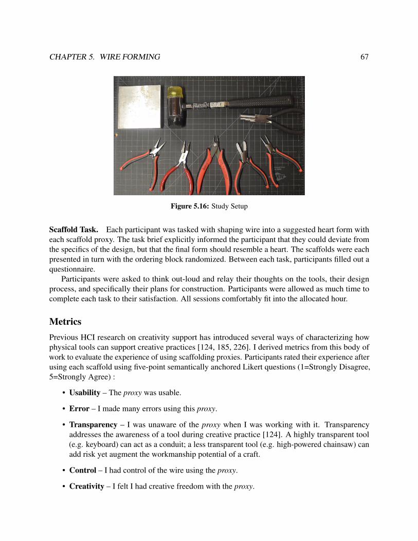
CHAPTER 5. WIRE FORMING 67
Figure 5.16: Study Setup
Scaffold Task. Each participant was tasked with shaping wire into a suggested heart form witheach scaffold proxy. The task brief explicitly informed the participant that they could deviate fromthe specifics of the design, but that the final form should resemble a heart. The scaffolds were eachpresented in turn with the ordering block randomized. Between each task, participants filled out aquestionnaire.
Participants were asked to think out-loud and relay their thoughts on the tools, their designprocess, and specifically their plans for construction. Participants were allowed as much time tocomplete each task to their satisfaction. All sessions comfortably fit into the allocated hour.
MetricsPrevious HCI research on creativity support has introduced several ways of characterizing howphysical tools can support creative practices [124, 185, 226]. I derived metrics from this body ofwork to evaluate the experience of using scaffolding proxies. Participants rated their experience afterusing each scaffold using five-point semantically anchored Likert questions (1=Strongly Disagree,5=Strongly Agree) :
• Usability – The proxy was usable.
• Error – I made many errors using this proxy.
• Transparency – I was unaware of the proxy when I was working with it. Transparencyaddresses the awareness of a tool during creative practice [124]. A highly transparent tool(e.g. keyboard) can act as a conduit; a less transparent tool (e.g. high-powered chainsaw) canadd risk yet augment the workmanship potential of a craft.
• Control – I had control of the wire using the proxy.
• Creativity – I felt I had creative freedom with the proxy.

CHAPTER 5. WIRE FORMING 68
• Quality – I am happy with the final design.
• Agency – Given a proxy, I feel capable of making my own customized designs.
The questionnaire additionally asked participants to rank the three scaffolds in terms of speedand quality of design.
To describe the creative session, I took an informal measure of flow, or the absorption withthe activity at hand. Flow is a common metric for measuring engagment [35] and while variousmethods exist for assessing flow, many techniques leverage Experience Sampling Method that hasthe potential to interrupt a creative workflow [36]. I focus on one measure of flow – temporary lossof time – which can be measured unobtrusively. I calculate flow as the difference between perceivedand actual completion time such that if a participant completes a task in 11 minutes, but perceived itas taking 4 minutes, I denote a flow measure of –5 minutes.
AnalysisI used a within-subjects 2x3 factorial study design with two factors: experience, with two types -novice and experts; and scaffold, with three types - jigs, stencils, and schematics. Each participantcompleted the same design using each of the scaffold types. The order of the scaffolds wascounterbalanced using a Latin square. Twelve participants completed 3 tasks each for a total of 36tasks completed all together. Due to a small sample size and semantically anchored scale data, Ilook at descriptive statistics.
For qualitative analysis, I transcribed the think-aloud protocol of each session, the post-studyinterview, and reviewed study notes describing participant construction patterns for each scaffold.This data was axially-coded; I specifically annotated instances of planning and wayfaring. Theresulting codes were refined and synthesized into themes presented alongside scaffold descriptionsin Section 5.8.
5.10 ResultsI first report quantitative results from the workshop session and the study questionnaire.
Session ResultsOverall, each session statistic is described in Table 5.10 and reflects the unique and diverse creativesessions with each scaffold.
Completion Time (min) Quality (Rank) Speed (Rank)
Jig (6.2 ± 2.0) (1.3 ± 0.8) Jig (1.0 ± 0)
Schematic (7.8 ± 3.3) (2.3 ± 0.5) Stencil (2.3 ± 0.5)
Stencil (10.4 ± 3.1) (2.4 ± 0.7) Schematic (2.7 ± 0.5)

CHAPTER 5. WIRE FORMING 69
Sessions varied widely in completion times from either participants dealing with or recoveringfrom error or engaged exploration. Stencils, which had the longest average duration time, wasalso the scaffold in which many participants chose to deviate from the original form. The moreopen-ended exploration of wire forms caused many participants to have trouble finding a place tostop. Participants agreed that jigs allowed them the quickest and most accurate wire forms; theresult from the jig was used as a gold standard since the criteria for quality, as self-reported byparticipants, was symmetry, smoothness of curves, and low marring or blemish on the physicalwire. Despite jigs consistently ranked above the other scaffolds, participants reported a different andvalued experience with each scaffold. These qualities are described alongside scaffold descriptionsin Section 5.8. The results are mirrored from Likert responses to usability and quality (Table 5.10,only total averages are reported due to similar responses between novices and experts).
Scaffold Usability Quality
Schematic 4.1 ± 0.7 3.1 ± 0.9
Stencil 4.0 ± 0.5 3.6 ± 0.9
Jig 4.5 ± 0.5 4.3 ± 0.7
Questionnaire ResultsSummary statistics for responses for the questionnaire are reported in Figure 5.17. I then discussinterview responses in the context of specific observations and insights from the study.
Error Control Transparency Creativity Agency
(Low)1234
Like
rt R
espo
nse
Schematic Stencil Jig(High)5
NOVICE EXPERT NOVICE EXPERT NOVICE EXPERT NOVICE EXPERTNOVICE EXPERT
Figure 5.17: Questionnaire Results
Error. Compared to other scaffolds, wires shaped with the jig were subject to an additional levelof scrutiny. Slight imperfections in symmetry were viewed as major flaws, whereas in the other twoscaffolds such asymmetry was embraced as a “handcrafted” look. The amount of guidance the jiggave them changed the narrative of agency. When responding to error, users attributed the errorto the jig; whereas, in the stencil and schematic condition, they blamed their own skill. One uservocalized that she did not view the jig as a tool, but as an extension of her hand:

CHAPTER 5. WIRE FORMING 70
Participant Novice #3: I relied on my hands mostly, not the hand tools. For me, thejig was the hand part.
Control. As anticipated, experts reported a greater experience of control than novices in theschematic condition, specifically when working with only hand tools. This difference in perceptionsof control suggests that, as anticipated, there is a stage where a practitioner develops confidencewhen working with new materials. In providing fabrication assistance, jigs and stencils providedelements of this control.
Transparency. All three scaffold types were reported to blend into the making process, whereparticipants placed much more focus on the wire. For experts, using the schematic to evaluate theirdesign against reintroduced awareness in this scaffold.
Creativity. There was no notable difference in the creative freedom users associated with eachscaffold. For each scaffold, participants found a way to reappropriate control of the wire form anddeviate or otherwise find creative value from the design. Although novices reported less creativefreedom with the prescribed form of the jig, they would, if successful, be elated at being ableto make a professional-looking form. In particular, experts reported more creative freedom overnovices for all scaffolds, suggesting that paths for deviation were more visible with backgroundknowledge of wire wrapping.
Agency. In reflecting on their ability to make custom designs with each scaffold, participantsfelt more support and ability in using jigs. For novices, stencils provided both assistance but alsoinvited enough creative curiosity to continue making forms. Experts showed more preference forthe unrestricted fabrication that schematics offered.
−10 −5 0 5 10
Novice
Expert
Time (minutes)
Schematic Stencil Jig Flow Region
Figure 5.18: Flow as a measurement of engagement. The boxplot depict the difference in perceived andactual completion time. Areas in the texture ‘+’ field indicate the participant lost track of time.

CHAPTER 5. WIRE FORMING 71
Perceptions of Flow. Flow was calculated for each scaffold session and is depicted in Figure 5.188.Sessions with negative flow indicate a larger effect on time perception and a stronger experience of“losing track of time” and engagement. While all scaffolds existed at some degree of flow, stencilshad a noticeably larger effect with engagement for both experts and novices. For experts, jigs werefound to be less engaging. For novices, schematics had a large variance in eliciting flow, especiallysince these sessions had mixed results with users being able to accomplish wire-bending goals.
Study ObservationsConstruction fixation. The within-subjects study design exposed all participants to each scaffold.While the scaffolds were presented were block randomized, I observed a relationship between thefirst scaffold presented to users in their workshop session and the way participant’s constructed theirdesign using the schematic. Notably, the schematic did not enforce a specific construction strategy.I depict these construction patterns in Figure 5.19.
SCHEMATIC-FIRST
JIG-FIRST
STENCIL-FIRST
Figure 5.19: Construction patterns were highly dependent on the first scaffold that was presented toparticipants. Schematic-first users moved with step-wise similarity, jig-first followed a linear progression,while stencil-first compartmentalized forms – an expert trait.
• Schematic First - These participants moved closer to the final design with each step. However,if a step did not bring the design closer to the desired form, these participants would becomemore apprehensive and stop manipulating the wire as freely.
• Jig First - These participants followed a linear construction pattern, i.e., starting by formingone end of the wire and progressively shaping the rest of the wire, often being unable to
8 Time perception follows a linear Weber law with median k = 0.77 [5] which suggests that we would still seesimilar (albeit less profound) trends if we adjusted for perception error.

CHAPTER 5. WIRE FORMING 72
allocate enough material to achieve symmetry successfully. This construction pattern followsthe construction strategy of the jig proxy, where a design is built up from end to end.
• Stencil First - These participants compartmentalized their construction into stages, isolatingthe more complex endloops, establishing symmetry with the heart curves, before finallyintroducing the heart bend. This strategy minimized the amount of interaction betweendifferent components of the design.
This priming effect suggests a construction fixation, or a cognitive bias that limits a person toconstruct a design in a prescribed way. This bias presents a unique opportunity for the design ofmaking tools: construction methodologies can be influenced by computational proxies to encourageexpert best practices.
5.11 Discussion
Figure 5.20: Wire-wrap Artifacts of Expert Participant 4
Facilitating a Morphogenetic WorkflowDespite some scaffolds encoded only a single form, the workshop revealed ways form-generatingbehaviors could emerge with physical proxies. The perception of the jig as a guaranteed successencouraged many participants to creatively reappropriate the mode of production offered by thejig. Participants deviated from the prescribed ordering of the jig or used helper geometries in theirdesigns. Already commonly used in digital fabrication practices, templates offer a guaranteedsuccess, however unlike the jig that introduces cognitive bias in “viewing everything as wrappable,”a template has a more limited influence on creative actions. The jig introduced a clear cognitive bias– wrap-thinking – that as an element of a larger environment could support a bricolage practice.
For experts, discerning wrap-thinking was easier as deviation points were easier to discern.The act of creating ambiguity in where to start, where to go, and where to end invited this type of

CHAPTER 5. WIRE FORMING 73
thinking. Future proxies could develop methods of facilitating wayfaring and indicate to the userthe multiplicity of forms that can exist, such as with parametric vase, that can ‘ghost” its designspace and give physical cues to potential deviations. Stencils were similarly viewed as elements ofa repertoire. Participants negotiated emerging forms and trajectories with the variety of tools andstencils laid out in front of them.
Maintaining a Material PracticeFor many novice practitioners, the experience of working with a physical material introducedsignificant risk — the risk of not liking their design, risk of others judging their work and abilities,risk of unwisely investing time and resources. Thus, one of the most substantial challengesin sustaining practitioners in a practice is mitigating the risk involved with making. The threescaffolds demonstrated how the perceptions of risk would change the creative goals, process, andinterpretations of the outcomes.
Ritual and Practice. With jigs that minimized the most risk, I encountered behaviors similarto needlecraft, where the muscle memory of physical action reduced the cognitive load on themaker. The “mindless” act of wrapping a wire around a form introduced an element of ritualpractice, instilling pleasure in the act of making in being able to produce accurate, professionalresults. While such an interaction may seem somewhat limiting, existing theories of makingraise the possibility that even repetitive or habitual creative actions can contribute to the joy ofmaking [124] and that merely engaging in the process of creation has “intrinsic pleasures ofcreative action” [151] and matching the challenge and skill needed to execute a design becomesa source of personal enjoyment [182]; such self-expression has large socio-cultural benefits [10].Foregrounding the spiritual and devotional qualities of a ritual practice, such as gardening, has beenshown to be made possible through electronically augmented tools that make practitioners awareof their repetitive actions and movements[90]. For creative development, sustaining a practice iscentral to transitioning from everyday creativity (little-c) to professional creativity (pro-C) [100].Incorporating ritual elements is a method to reduce risk, develop familiarity and comfort with amaterial, and behaviorally engage the body in sensemaking.
Who’s to Blame? Failures, or the subjective emotional experience caused by the interpretation oferror as unrecoverable, can yield negative attitudes towards continuing or pursuing a practice [194].In the workshop evaluation, participants had widely varying scrutiny of error and coincidentallyfailure associated with each scaffold. Designs made with jigs, which offered the most physicalassistance, bore the highest level of scrutiny. However, with schematics and stencil, imperfectionswere associated with qualities and aesthetic of a handcrafted artifact. Notably, jigs were seen asan extension of the hand, yet were prescribed a level of scrutiny that would is associated withmachine-made artifacts. This suggests that the agency given to a practitioner in the physical makingprocess can be used to develop craftsmanship and resiliency towards interpreting errors as failures.

CHAPTER 5. WIRE FORMING 74
Proxy-Mediated Knowledge TransferThe scaffolds allowed practitioners to choose their own level of fidelity and workmanship. Schematicprovided evaluation criteria that participants used to sanity check their designs. Although thisencouraged a modular construction process, the sanity check did not provide an opportunity forparticipants to reflect on the overall design process and anticipate errors. This lack of reflectionsuggests that the act of evaluating the validity of a design process must carry a cost or risk in orderto elicit more reflective behaviors.
Extending to other Material PracticesI showed that through medium-aware design that takes into account the unique properties andcultural histories of materials, proxies can assist, enhance, and extend the wire-wrap medium. Otherdomains can benefit from such passive proxies; for instance, a ceramics proxy practice might involvestencils that form lathe bits for use with a pottery wheel. Because of the passive nature of proxies,participants found value in a proxy’s non-intrusiveness and proposed a practice which follows:sketching an idea and “wrestling the material”; converting interesting forms into stencils; refiningthis into a final artifact. It is imprudent to disregard the new cultural histories that are arising fromdigital fabrication machines; works such as Filament Sculptures [110] that creates 3D forms from a3D printer’s characteristic extrusion demonstrate the gray area that exists between what is a tooland what is a material.
Limitations. Although the workshop captured a variety of different making styles and approaches,the evaluation is ultimately limited by the observations of a short creative wire-wrapping session.A longitudinal study could better capture the ability for different scaffolds to engage practitionerscreatively. As noted in the results section, although the scaffolds were randomized in orderpresentation, I still observed some priming effects such as construction fixation. While this reaffirmsa tool’s influence in a bricolage practice, it also suggests that naturalistic study designs can bettercapture the environmental variables that are known to influence creative practice.
5.12 SummaryThis chapter argued for an alternative digital fabrication workflow to the CAD-CAM pipeline thatpromotes a morphogenetic, or material-forward, way of making. I explored how such a workflowmight operate in symbiosis with digital fabrication and a material practice known as wire-wrappingby developing a Crafting Proxies which function as an armature.
Our investigation revealed tacit knowledge that is inaccessible from sophisticated Computer-Aided Design (CAD) tools with abstracted representations of wire (e.g., Finite Element Model,bending simulations). In engaging with wire wrap practitioners, online resources, and personalpractice, I discovered key techniques that professional wire wrappers employ to converse with wireincluding: dealing with work-hardening through axial deformations, a coil-and-cutting technique

CHAPTER 5. WIRE FORMING 75
for batch-producing similar wire forms, and a material undo, smoothing work-hardened bends withnylon pliers.
I developed a wire-wrapping CAD tool that incorporated and annotated a vocabulary of wireforms used in the wire-wrapping tradition and produced custom armatures, allowing practitionersdirect contact with wire. The computational design for generating armatures built custom wrappinggeometries around areas of high curvature; it also incorporated the axial deformation technique bycreating a constantly rising geometry that would produce a non-planar wire shape that when pressedflat (via axial deformation) would form the target wire shape.
By changing design parameters in our algorithm, I created three variants of armatures that scaf-fold the type of assistance provided in shaping a wire, supporting zones of proximal development:
• Schematics - This armature presents information about a design to aid with planning actionsand serving as evaluation criteria.
• Stencils - This armature modularizes components of a design and physically assists withcreating variations of a design.
• Jigs - This armature assists with shaping wire with one, uninterrupted wrap, but is restrictedto assisting with forming wire into a single target design.
In a workshop user study, I characterized these armatures between two populations – novice wirewrappers and expert wire wrappers – to understand how each armature affects the wire wrappingprocess and the design decisions that elicit a morphogenetic way of making.
The study reveals that tools that introduce a clear cognitive bias, such as in the case of stencils andjigs, are beneficial for encouraging deviation. Tools that encourage tool-switching provoked moremorphogenetic actions, while encouraging ritual, or repetitive and mindful actions, were importantfor sustaining interaction with a material, instilling resiliency, and finding joy with the practice. Ifound this ritualistic quality of making to be best suited for developing wayfaring, developing apractice where the wire (and armature) more completely guide the course of action. Schematics,although the armature with the greatest potential for a material encounter, also introduced the largestpotential for error. This workmanship of risk coupled with the clear evaluation metric the schematicprovided served as an important motivator for eliciting craftsmanship.
From designing an armature to operate as part of a human-in-the-loop fabrication pipeline, Ideveloped intermediate-level knowledge for how to incorporate the benefits of a digital medium(e.g., reprinting a variation, sharing a design) while facilitating a material encounter, embeddingtacit knowledge as affordances, and structuring physical and cognitive assistance to create zones ofproximal development. I take these design decisions forward to inform how Crafting Proxies canprovide similar support but for immaterials that do not share the rich, responsive physical cues thatmaterials like wire provides.

76
Chapter 6
Light Forming
In this chapter, I explore how a Crafting Proxy might be designed to act as a mediator between animmaterial and practitioner. Unlike materials like wire, immaterials lack tangibility or perceivability.I explore one kind of immaterial, light, which although perceivable is difficult to physically manip-ulate or compose into forms, especially in form factors such as the Light-Emitting Diode (LED).However, the LED is a staple of Maker culture and hobbyist electronics. Working with LEDs isrelatively straightforward, involving a low-cost electronic component and a simple circuit to convertelectrical energy into visible light. Light is a visually expressive, engaging, and captivating material,as is a testament in its ubiquity in electronics, festivals and carnivals, and urban spaces. However,the way light is used in practice with LEDs only thinly captures the full expressivity of light, but theimmateriality limits how it can be used by material practitioners.
I apply a compositing strategy, previously demonstrated to be successful for immaterials likecomputation [201], and apply it to other immaterials in order to understand how compositing asa design strategy can be generalized. Compositing uses a physical material as a proxy, binding itto an immaterial in order to remap its behaviors, forms, and structures into physical cues. Usinglight as our immaterial of interest, I describe the design of a luminaire design tool that facilitatesinteractions with light as a craft material1.
I first distill a conversational profile by surveying how different communities of practice haveworked with light and through a formal analysis of light artifacts. Since light is a visual and reactivematerial, a host of physical materials can serve as proxies. In this design process, I introduce acomposability design stage, developing computational design algorithms for configuring how lightand reflective and refractice materials can be configured to orient, bend, shape, diffuse, and composelight (via Secondary Optic Elements (SOEs)). I describe how coupling these algorithms with anopen-ended design tool can support knowledge production in a material epistemology.1 Elements of this chapter were previously published in: Cesar Torres, Jasper O’Leary, Molly Nicholas, and Eric
Paulos. “Illumination Aesthetics: Light As a Creative Material Within Computational Design.” In: Proceedings ofthe 2017 CHI Conference on Human Factors in Computing Systems. CHI ’17. New York, NY, USA: ACM, 2017,pp. 6111–6122. DOI : 10.1145/3025453.3025466.
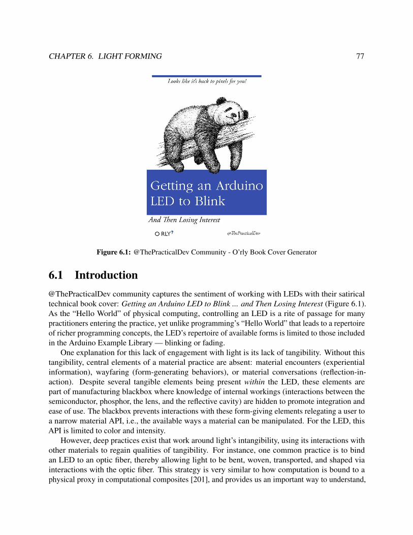
CHAPTER 6. LIGHT FORMING 77
Figure 6.1: @ThePracticalDev Community - O’rly Book Cover Generator
6.1 Introduction@ThePracticalDev community captures the sentiment of working with LEDs with their satiricaltechnical book cover: Getting an Arduino LED to Blink ... and Then Losing Interest (Figure 6.1).As the “Hello World” of physical computing, controlling an LED is a rite of passage for manypractitioners entering the practice, yet unlike programming’s “Hello World” that leads to a repertoireof richer programming concepts, the LED’s repertoire of available forms is limited to those includedin the Arduino Example Library — blinking or fading.
One explanation for this lack of engagement with light is its lack of tangibility. Without thistangibility, central elements of a material practice are absent: material encounters (experientialinformation), wayfaring (form-generating behaviors), or material conversations (reflection-in-action). Despite several tangible elements being present within the LED, these elements arepart of manufacturing blackbox where knowledge of internal workings (interactions between thesemiconductor, phosphor, the lens, and the reflective cavity) are hidden to promote integration andease of use. The blackbox prevents interactions with these form-giving elements relegating a user toa narrow material API, i.e., the available ways a material can be manipulated. For the LED, thisAPI is limited to color and intensity.
However, deep practices exist that work around light’s intangibility, using its interactions withother materials to regain qualities of tangibility. For instance, one common practice is to bindan LED to an optic fiber, thereby allowing light to be bent, woven, transported, and shaped viainteractions with the optic fiber. This strategy is very similar to how computation is bound to aphysical proxy in computational composites [201], and provides us an important way to understand,

CHAPTER 6. LIGHT FORMING 78
contrast, and extend a composite approach to other immaterials that are problematic to materialpractices.
Using this compositing design strategy, this work examines how we might impart materialqualities to the LED to expand the available repertoire of light forms, understand how creativeengagement can be elicited for light and other immaterials, and reflect on the limits of compositingas a material transformation technique.
Our design method first examines how different communities of practice use light as a material.Through a formal analysis, I examined both illuminated artifacts and workflows with LEDs to resolvehow material and social factors influence how light forms emerge. I synthesize a conversationalprofile, acting like a persona, that informs how light can more readily communicate to a practitionerduring the act of making and defines a target light API.
The second step of our process is improving the composability of light, i.e., the extent towhich the light API can be accessed by the practitioner. Using best principles from optoelectronicsliterature, I created a digital fabrication pipeline for creating luminaires, a structure for powering,housing, and controlling one or more lamps, decomposed into three parts: the control layer, abeam-shaping layer, and a diffuser layer. Leveraging computational design techniques, I configuredeach of these layers to be able to capture a wider range of the light API.
Figure 6.2: Luminaire Design Tool, Simulation Interface, and Fabricated Luminaire
The results are synthesized into a luminaire CAD tool that acts as an mediator, allowing light tobe used as a craft material (Figure 6.2). Using ray tracing, I simulate light interactions with the LEDand different materials to better relay the forms, behaviors, and structures of light. The fabricationthen produces a set of 3D models, that when fabricated and assembled, produce a bespoke luminaire.
Using the tool, I create exemplar artifacts to annotate the range of Illumination Aestheticsenabled by access to an expanded light API. A workshop evaluation with 11 participants usingour tool also indicates how a compositing approach communicated to participants an expandedrepertoire of light forms, altered perceptions of light as a creative material, and elicited a deeperengagement with light as a medium. In summary, the contributions of this work include:
• a conversational profile of light that synthesizes the ways different communities of practiceuse light as a material

CHAPTER 6. LIGHT FORMING 79
Figure 6.3: (left) Olafur Eliasson, The Weather Project (2003), (center) Daniel Rozin, Wooden Mirror (1999),(right) Printed Optics [210]
• a luminaire CAD tool that exposes a more expressive light API for manipulating and forminglight and operationalizing the concept of an Immaterial Mediator
• exemplar artifacts that annotate novel light forms
• a thematic analysis of the creative process of 11 participants using our tool
The findings of this work are used to a reflect on how configuring the LED as a compositeadheres and challenges computational composites. This is used to inform design implications for ageneralized compositing method that can be used for a range of different immaterials.
6.2 Related WorkA diverse community has explored methods of form-giving with light. We organize these relatedworks based on how light is manipulated and then describe the experiential qualities of the resultingforms.
RefractionRefraction refers to the bending of light caused by light waves traveling at different speeds betweenmediums of different densities. Refraction behaviors follow Snell’s law where light is deflected atthe interface of media A and media B, according to:
sinθA
sinθB=
vA
vB=
nB
nA
where θA is the angle of incidence, θB is the angle of refraction, vX is the respective velocity and nXis the respective index of refraction of waves in medium X.
As a form-giving element, practitioners make use of light’s refractive qualities to blur anddistort vision. In Eliasson’s The Weather Project, a fine mist of water refracts light and is used tomaterialize moving indoor weather formations [45].

CHAPTER 6. LIGHT FORMING 80
Figure 6.4: (left) Jim Campbell, Exploded Views (2011), (center) László Moholy-Nagy, Light-Space Modu-lator(1930), (right) Gjon Mili, Picasso draws a centaur (1949)
Light Tubes. By configuring a material with a lower refractive material, or cladding, around amaterial with a higher refractive index, or core, a phenomenon known as total internal reflectioncauses light to be confined within the core material. As the basis for fiber optics, total internalreflection is used to transport light (and respective images) across distances. Early work by DisneyResearchers used fiber optics to transfer images from a projector into animated heads allowingdynamic images to register on diverse surfaces [113]. Willis et al. [210] further demonstrated thefeasibility of 3D printing light pipes and lenses within geometries to channel light and create novelillumination and sensing capabilities. By bundling light pipes and routing them through a structure,this technique has been shown to create screens on both spherical geometries [21] and arbitrarygeometries [147]. The resolution of this display technique is largely dependent on the density oflight pipes. Ultimately, each individual light pipe terminates and forms a pixel. The dominateresulting form is a screen which inherits the experiential qualities of television and the motionpicture.
Lenses. Lenses are comprised of a repertoire of specific geometries that leverage refraction toprecisely focus, collimate, or redirect light rays. The range of possible beam forms is expanding withadvances in optics, including double-cylindrical lenses to shape light into rectangular beams [30]or micro-array lenses to homogeneously diffuse light [174]. In a computational design process,Papas et al. fabricated lenses with refractive geometries to hide, reveal, and obfuscate images placeddirectly underneath [142]. This process utilized simulated annealing to optimize facet geometriesto refract light in a pre-described manner. Readymade-lenses, embedded with magnets, weredemonstrated to enable a wide range of tangible interactions with printed images [111].
Reflectors & ReflectionFor reflective properties, Matusik et al. [123] demonstrated the feasibility of matching BidirectionalReflectance Distribution Functions (BRDFs) with linear combinations of reflective inks. Utilizingthe subtle reflective properties of wood, Daniel Rozin’s Wooden Mirror actuated a grid of smallwooden “pixels” to different orientations to create changes in value and form images [167].

CHAPTER 6. LIGHT FORMING 81
Shadow-CreationIn Exploded Views, Jim Campbell creates three-dimensional animated shadows by controlling theintensity of several light sources suspended in a dense irregular grid [25] (Figure 6.4). Using asingle light source and occluding resin geometries, Kumi Yamashita shapes light and shadow intocomplex forms [217].
Dynamic, Reactive, and MotiveDynamic light has been explored in early work such as László Moholy-Nagy’s Light-Space Modu-lator which spun reflective geometries to create visceral moving light installations [129]. Throughlong-exposure photography, the persistence of light was captured as a drawing and painting mediumin influential works like Gjon Mili’s Picasso draws a centaur [64].
As an interactive medium, the active, changing nature of light affords playful, information-richinteractions. Harrison et al. surveyed the design space of point lights in modern devices, notablylinking common actuation behaviors ("On w/ Bright Flash") to functional evaluations ("Notifica-tion") [73]. Design work in this space has also explored light as an active patina, assigning visuallight patterns to recorded user interaction history and activity with a tabletop surface [59]. Interactiveobjects have also been enabled by sensing changes in light through embedded optomechanics [21,147, 210]. I see our technique working in tandem with optomechanical sensing, although I focus onexpanding illumination aesthetics to enable even richer interactions.
Space-FillingNotably, these works demonstrate a material and space-driven exploration of light. Utilizingprojected light, James Turrell influences a viewer’s depth perception by simulating 3D forms on 2Dspaces (Shallow Space Constructions) [197].
SymbolicLight has also been explored conceptually; most well known in this space, Dan Flavin createdlight objects that function as systems of investigation [50]. Pierce et al. further described otherphenomenological dimensions of light in electronic objects as tied to the object, its material, andits source [150]. Our work particularly explores the design dimensions of illumination affordedthrough the optical manipulation of light. Light has been shown to afford emotional reactions andinterpretations in objects such as luminaires [81].
6.3 Conversational ProfileTo identify the conversational profile of light, I conducted a formal analysis [133, 11] to distill howform-giving elements are “arranged and function within a composition.” I specifically delineatethe different established traditions and practices across three light artifacts: the electronic light

CHAPTER 6. LIGHT FORMING 82
(a simple LED, RGB LED), the computational light (a computationally-controllable LED), andmaterial light (exemplar uses of LEDs as a craft material). Our analysis approaches these materialsfrom a craft lens, focused on mapping the range of expressions encountered with that material withthe underlying rationale for why such expressions are chosen.
Electronic Actors: The LED
Figure 6.5: Adafruit LED Matrix (1613)2
The LED, or light-emitting diode, is a common electronic component found in hobbyist elec-tronic toolkits is often found unlabeled or packaged in grab bags. Simple LEDs activate a semicon-ductor that emits photons with a specific emission spectrum, or color, when an electrical current isapplied. By combining multiple semiconductors with different emission spectra (typically a red-,green-, and blue-dominant spectrum) within a single package, an RGB LED can be configured toemit a wider gamut of colors by controlling the intensity of each semiconductor component.
Integration. Introducing an LED into a circuit is relatively simple when electronic parametersare known; however, most packages do not encode this information. Common heuristics are usedto acquire these parameters, limiting the current flow by introducing a 500 Ω resistor in series,applying a typical nominal voltage VS like 5V, and measuring the forward voltage drop VF [112].Lastly, a resistor is integrated to act as a current limiter to the common operating current (10-30mA) range as follows:
RS =VS−VF
IF2 https://www.adafruit.com/product/1613

CHAPTER 6. LIGHT FORMING 83
Control. Introducing a variable resistor, such as a potentiometer, allows the current limiter to bedynamically controlled, achieving fading or color selection (i.e., knob for each RGB component)behaviors. More complex configurations use a pulse-width modulation (PWM) controller tosend a square wave that powers the LED on and off; at specific frequencies, these on-off pulsesare perceptually averaged, allowing the LED intensity to be controlled in a fashion similar to apotentiometer [42].
Figure 6.6: The Matrix Circuit Pattern. A circuit pattern for selectively controlling an LED.
Controlling more than one LED is expensive, requiring an individual control line for each LED.Alternatively, LEDs can be arranged in a matrix configuration allowing control to be specified witha common row and column input (Figure 6.6). This configuration reduces the number of inputcontrol pins to the number of columns and rows in a matrix. LED drivers and shift registers simplifythe control logic for this configuration and are the basis for controlling screens, or high-densitymatrices of LEDs.
Expression. The LED thus offers the following parameters for controlling the expression of light.
• Luminous Intensity - The intensity of light produced by the LED is controlled by altering thecurrent with a resistor or changing the duty cycle of a pulse-width modulated (PWM) signalto an LED.
• Color - The emission spectra is controlled by changing the intensity of three LEDs in apackage (red, green, blue).
• Viewing Angle - Most LEDs contain lenses that shape and direct light across large distances(LEDs are typically manufactured for large screen applications); commonplace LEDs haveviewing angles around 30 or 60; most LEDs have a non-uniform light distribution with most

CHAPTER 6. LIGHT FORMING 84
of the energy produced directed in the 0−10 range. The restricted viewing angle influencesmany designs to express the formal aesthetic of a point-light.
Forms. In interactive installations and e-textiles, light is often overwhelming – interactive lightsare especially attention-grabbing, restricting the audience’s attention to these elements withoutreflecting on the other formal elements in the structure. When LEDs are integrated with passivemediums, the express a sensation of "being tacked on" not fully integrating into the passive materialspace. Through its fast, instantaneous changes, LED’s propensity to grab attention matches the high-energy social events like concerts and music performances and fails to communicate a "preciousness"that other materials like wood and leather share.
Dissemination. Photographing LEDs is notoriously difficult since taking a photograph head-on,in the direction of the viewing angle, causes most camera sensors to overexpose; even high-dynamicrange photography cannot adequately capture the experience of light in a space. This limits thecommunicability of different light configurations.
The complexity of the matrix and LED driver circuit influenced the growth and use of readymadedot-matrix and 7-segment displays. Due to the complexity of circuit traces, dedicated circuit boardsare needed and available from commodity electronics manufacturers, but the majority use a standardmatrix layout.
Computational Actors: the Smart LED
Figure 6.7: Luminous LED Strip Light, a commodity smart LED strip3.
3 Image Credit: Luminous from https://www.luminousindia.com/75w-led-strip-light-1222.html

CHAPTER 6. LIGHT FORMING 85
Configured with a microcontroller, LEDs can be controlled computationally powered, typicallypowered by a general purpose input-output (GPIO) pin configured to output a PWM signal, emulat-ing the previous electronic configuration. Smart LEDs offset elements of this computational controldirectly onto the LED package.
Integration. The main restriction for using LEDs with a microcontroller is the need for 1:1 controllines; smart LEDs significantly reduce the number of control wires to one or two. By connectingLEDs to each other, LEDs form a communication strip that propagates information down the linkedstructure.
Control. Many smart LED control mechanisms employ a two-wire communication protocol(I2C or SPI) or single-wire communication to individually control many LEDs. This physicalarchitecture aligns with the data structure used to program them (e.g., an array). While greatlysimplifying physical setup, smart LEDs introduce an initial digital configuration step before anythingis physically experienced, limiting its potential to support a material encounter.
Expression. With programmatic control, smart LEDs expose an light API that provides a stream-lined control interface for controlling RGB components. This allows practitioners to control andintensity. Commodity LEDs provide 8-bit or 12-bit resolution of intensity values. However, thesevalues are mapped to physical intensity, existing in the language of the hardware, as opposed tomapping to perceptual intensity.
Forms. When coupled with a microcontroller, the LED and computation form a computationalcomposite. Specifically, the forms, structures, and behaviors of computation emerge as physicalcues. For instance, a common interaction aesthetic is for LED signs or products to cycle betweenred, green, and blue colors. The computational forms are exposed when experiencing the LED sign– the deterministic cycling expose a computational loop; the alternations between red, green, andblue expose an array data structure ([R, G, B]). This lighting behavior represents one of the lightform that requires the least amount of resistance from the computational material.
However, having colors represented in RGB space biases the colors that are used in light forms.For example, red, green, and blue are simply one channel at maximum output, but choosing acolor like yellow (RGB = (255, 255, 0)) is more difficult to remember and implement. While astraightforward process (looking up the color on an RGB table), the additional effort in carryingout this action restricts the readily available behaviors, influencing many RGB designs to be biasedtowards red/green/blue behaviors.
A quality of the computational material is also exposed by the RGB cycles – digital atomicity.Atomicity refers to "an operation appears to occur at a single instant between its invocation and itsresponse". This term is coincidentally used to refer to database transactions that "are guaranteed toeither completely occur, or have no effects". In the RGB cycle, the fact that the previous red statedoes not interact or interfere with the oncoming green state is a byproduct of the atomicity of thedata structure holding the different states and the update speed of the LED. Programming an LED to

CHAPTER 6. LIGHT FORMING 86
have a "residue" (or hysteresis) from previous signals is a way of encoding richer expressions thatdo not have a digital aesthetic (i.e., atomicity), but require a level of computational craftsmanshipthat is not supported by LED practices.
Dissemination. Smart LEDs are having the highest success in emerging makerspaces. Theavailable light API, via programmatic control, as well as successful hardware form factors such asthe circular NeoPixel rings have altered the landscape of LED uses to include rotational elements.Programs are easily disseminated through online communities and the established 3D models in3D printing repositories that directly house and integrate common configurations. Coupled withan infrared control module and an adhesive backstrip, LED light strips of arbitrary length havepermeated the commercial market, allowing practitioners to integrate them as architectural elementsand expose a finite light behavior library.
Over the past years, we have seen a significant shift from tradition matrix form factors towardsring form-factors popularized by Adafruit Industries and the Maker community. These formsleverage recent innovations in LED design that integrate inexpensive control modules in smartLEDs (DotStar/Neopixel), allowing hundreds to be controlled via one or two data wires. Thesedata wires need only be connected from the output terminal of one LED to the input terminal of theother. This relaxed circuit constraint, alongside flexible PCB fabrication techniques, influenced theavailability of LEDs in strip form factors that have been readily incorporated into architecture and ahost of hobbyist projects.
Mechanical Actors: The Virgén de Guadalupe Fiber Optic LampAs a counterexample to computational and electronic light actors, I describe a mechanical lightartifact found in a fiber optic lamp. Depicted in Figure 6.8, the Virgén de Guadalupe Lamp (depictedin 6.8) was encountered in Albany, CA at a local lighting shop. The lamp features a religious effigy,popular in Latin American households, surrounded by a glow surface halo4.
Integration. Light originates from a single, higher power lamp secured beneath a rotating plasticdisk. Above the disk is a bundle of fiber optic cords that transports light from the bulb to the otheredges of the halo. The fiber optic strands texturize the light, terminating at different lengths andcreated a clusters of small pixels at the edge of the effigy’s halo.
Control. Color is controlled by a rotating a tinted plastic disk that sits between the lamp and thefiber optic bundle. Light passes through the tinted disk, “becomes colored,” and then is transportedby the optic fiber. The sequential motor rotates the disk at 5-6 RPM. The patterns on the disk areused to control the duration of a specific color, using the arc of a pie slice. Since the optic bundle4 Light has often been connotated as a religious material; in primarily candle-lit medieval churches, gold leaf on
paintings would create a glowing surface that contributed to an otherworldly quality of the subject; the flickeringof the candlelight added to a vital quality [71].

CHAPTER 6. LIGHT FORMING 87
Figure 6.8: A lamp of the Virgen de Guadalupe cast in resin and inlaid with fiber optics. (center) Amechanical stepper motor rotates a stained glass disk above a lamp bulb; fiber optics capture the coloredlight acting as a sequencer. (right) A light sequencer program; the fiber optics bundle "reads" in light passedthrough a colored disk. Manufacturer unknown.
"reads" the light values as a circular input head, the transitions between two colors are faded (withonly a few fibers picking up the color transition, followed over time by the rest of the fibers).
Here, I see several similarities to the computational LED — the rotating plastic disk acts as aprogram, encoding color instructions over time; the sequencer motor acts as a control loop, cyclingthrough the instructions; the optic fiber acts as a hybrid data structure where each fiber is mappedto an area in physical space.
Expression. Despite having similar mechanisms as a computational program, a mechanicalprogram allows behaviors to emerge that “go against the grain” of the computational program,similar to how placing coordinate systems from Cartesian to polar facilitates working with conicsystems. A different class of expressions are available through the mechanical program: first, itoperates at a different scale – individually programming the moment-by-moment behavior of eachvirtual strand LED would be a very tedious task; secondly, adding a fade in and out behavior wouldintroduce significant bottlenecks on the computational processor – this computation is offloaded toa simple linear gradient on the tinted plastic disk program.
Forms. Because of fiber optic’s light transporting properties, light follows the patterns of thestrands, materializing light in a wire form factor. These fibers are used to create streaks of light thatterminate in bright points (from light escaping the fiber optic). Although a point light, similar towhat we expect with the LED, these point lights are composed within a larger light composition,from the light forming a glow surface in the base cavity or from the refraction of light escapingthe fiber optic strands. The configuration of a circular optical read head and pie-slice program

CHAPTER 6. LIGHT FORMING 88
allows colors to transition gradually, unlike the sharp binary effect of digital atomicity found incomputationally-controlled LEDs. Through pattern variations in the pie-slice program, differentlight shimmer behaviors express an ethereal quality to the overall lamp aesthetic.
Dissemination. Significant integration costs (proper configuration of the motor, optic bundle,lamp) restrict the use of light with mechanical actors, however the synchronous motor as sequenceris common pattern in optic fiber lamps.
Light as Craft MaterialI analyzed artifacts that used LEDs with different material actors, each contributing to understandingthe conversational profile of light and areas in which the expression of light is restricted. Forthe LED, the weight of digital actors (the microcontroller, programming) and electronic actors(the potentiometer, PWM generator, matrix configuration) outweigh the role of light as an actor.Restricted to light API of a hard-coded viewing angle, color, or intensity, light acts as a second-classdesign citizen in these configurations. This is further exemplified by the ubiquity of designs withpoint-light forms.
Figure 6.9: An LED was cast in acrylic resin (PMMA) using a packing plastic as a mold. As the resincured, gases produced from the chemical reaction attempted to escape but were captured, forming bubbles.Light emitted from the LED interacts with these geometries, refracting and reflecting to form light gradients,shadows, and textures.

CHAPTER 6. LIGHT FORMING 89
The fiber optic in the Virgén de Guadalupe Lamp serves as an exemplar of a deep practice withlight; its more expressive qualities are mediated by its interactions with other materials includingthe fiber optic and the rotating program disk. In this way, the intangibility of light, which althougha physical phenomenon, cannot be used as a material by itself. Through its interactions withother materials, light is made tangible. To communicate this insight, Figure 6.9 depicts an earlyexperiment with casting an LED in an optically clear resin. The casting process used a discardedplastic tray as a mold. The process was imperfect with several bubbles forming during the resincuring process, however these trapped air bubbles created geometries that refracted light emanatingfrom the LED. Furthermore, the opportunistic shape of the mold from the discarded tray yielded ageometry where some light rays surpassed the maximum angle of incidence, trapping the light andcreating a edge illumination. Through its interactions with the refractive material its geometries,light was made tangible allowing new forms to emerge — creating shadows, filing space, andforming soft and hard edges.
From our formal analysis, I build and expand on four light behaviors lighting designer BradHindson [79] advocates are underutilized in design. I use the following Conversational Profile ofLight displayed in Table 6.1 to guide the design of our Crafting Proxy.
Light is Refractive and Reflec-tive
Light can be bent and redirected through both the intrinsic prop-erties of a material and its underlying geometry. I see theseproperties manifest in reflectors for creating spotlights, in fiberoptics to transport light, in lenses for collimating lenses to travellonger distances, or in the transparent faceted gems of a chande-lier.
Light is Sharp and Soft When light interacts with a surface, it can scatter create softdiffuse forms, or it can be focused to create sharp boundaries.Surface properties play an important role in defining this inter-action, found in diffusers like lampshades or through the use oflens geometries.
Light is a Shadow Creator Light is an interplay between illumination and shadow. Shadowsare found on a gradient (e.g., the darker umbra, or inner castshadow and the lighter penumbra, or outer cast shadow). Theperception of brightness is mediated by the simulatenous con-trast effect, or the perception of intensified difference when twocontrasting stimuli are juxtaposed, and brightness constancy, orthe effect of objects having the same level of brightness despitechanges in global illumination [65].

CHAPTER 6. LIGHT FORMING 90
Light is Space Filling Light can fill a small cavity or an entire room. Light is an archi-tectural form that can transform spaces. Descottes et al. [37] de-scribe six principles that facilitate the dialogue between light andspace – illuminance, luminance, color and temperature, height,density, and direction and distribution.
Light is Dynamic and Reactive Light is reactive, responding to the most minute changes in itsenvironment. We see elements of this reactivity captured inthe shimmer mechanical light sequences of the optic fiber lamp.While the dynamicity of light is often relegated to an on/offswitch or dimmer or Christmas light sequences, the potential oflight as a dynamic material is engrained in its reactivity. Light’sreactivity contributes to its quality of being attention-grabbing.
Light is Symbolic Light has been used as a material across history, carrying sym-bolic value from its use in representing the ethereal in gold leafpaintings of cathedral stained glass, to its representation of mod-ern innovation (i.e., the light bulb) and enlightenment, to moremodern representations of technology and the techno-aesthetic.
Table 6.1: A Conversational Profile of Light
6.4 Composability: Deconstructing the LEDIn this section, I explore ways of improving the composability of light, or the extent to which thelight API can be accessed by the practitioner and facilitate a wider gamut of the conversationalprofile with light (Table 6.1). Currently, the light API is limited to brightness, color, and viewingangle.
Our approach involved decomposing the LED into its separate components and building compu-tational design routines that gave practitioners access to the light-forming elements. When composedtogether, these elements form a luminaire – a device that produces, controls, and distributes light.The Illuminating Engineering Society (IES) [84] defines luminaires as consisting of: one or morelamps or LEDs, optical devices designed to distribute light, sockets for supplying electric power,and the mechanical components required to support or attach the housing.
Our computational backend decomposes these elements into three layers:
• Diffusion (3-5 mm): consists of materials with light scattering properties that can diffuse orproduce an even distribution of light.
5 Image credit [right]: Ashley Hunter at 1000 Bulbs from https://blog.1000bulbs.com/home/how-led-lights-work

CHAPTER 6. LIGHT FORMING 91
Figure 6.10: Luminaire Construction - Lamps are housed, powered, and controlled in the base level.Secondary optic elements in the beam-shaping layer shape light emitted from the lamps. The topmost diffusercontrols the presentation of light using light-scattering surface properties5.
• Beam Shaping (10 mm): shapes light emitted from an LED using computationally-designedSecondary Optic Elements (SOEs) made with refractive or reflective materials. For instance,an SOE can be designed to redirect light rays to run parallel to each other maximizing thelumens over a given area (i.e., collimating lens). Appropriately configured, this lens is thedriving technology that allows bike lights to be visible from a distance and evenly illuminatethe path in front of them.
• Control (1.5 mm): composed of LEDs, a microcontroller, and a power connector on a printedcircuit board (PCB).
I describe the features, computational design algorithms, and implementation details of eachlayer in the following sections. When then expose this expanded light API through a frontendluminaire CAD tool described in Section 6.5. This tool integrates these computationally designedcomponents with fluid direct manipulation interactions to allow creative control of light forms.
Control LayerPCB Layout. Inspired by the expanding control form factors of LED strips and NeoPixel rings, Icreated a computational layout algorithm that leverages the chaining circuit pattern to route powerand control to any number of LEDs. This allows PCBs to express non-linear and non-matrix LEDcompositions. I expose the algorithm as a trace-assistance mechanism which produces appropriateconfigurable files for PCB milling, etching, or sketching, custom to a luminaire design. Thismechanism automates the PCB design process, connecting LEDs using a strip-routing algorithm.

CHAPTER 6. LIGHT FORMING 92
A strip represents the shortest route that connects the inlet of one LED to the outlet of another,passes once through each LED. The LED orientation is unconstrained, and, as additional toolingconstraints, no path overlaps nor acute turns should exist.
APA102C footprintuser-defined ordering
footprint extension Adobe Illustrator Pattern Brush
orientationoptimization
2
31
Figure 6.11: Trace assistance routine. a) user annotates SVG, b) positions are extraced and LED orientationis optimized, c) optimal path is extracted, d) design files produced for several processes, e) different substratescan be used to create rigid or flexible PCBs.
The algorithm first takes as parameters a target design (specified as an SVG) that encodes theposition of a set of LEDs. Additionally, by projecting the LEDs onto a user-specified path p andsorting by path location, I obtain an ordering schema. When then carry out the following operations.
• Place the LED footprint at each LED position, extending the terminals of the footprint toprevent LEDs from resting on a curve or turn and improve solderability(Figure 6.11a).
• Generate a strip (a directed spatial graph) with 2-edge nodes at each LED terminal connectedas specified by the ordering path p.
• To optimize LED orientation, I stochastically reorient each LED and reconstruct the strip. Iutilize simulated annealing to guide the stochastic search, creating neighbor designs by chang-ing the orientation of the nodes and using an acceptance probability function P conditionedon the length of the strip.
The final result is an SVG with the circuit footprints of the LEDs, an editable path that connectseach LED from each respective input/output terminal to another. Using Adobe Illustrator’s PatternBrush, I then convert this trace into the circuit footprint required by the LED specification (Figure6.11c). The Pattern Brush allows for the proper configuration of behaviors on circuit bends. Iadditionally resolve the footprints for the microcontroller and power supply connector componentsat the start of the strip to complete the circuit design. For logical control, I add a footprint for an8-pin socket to hold an ATTiny85 microcontroller (DIP); for power, I affix a 3.1mm DC barrel jackfootprint at the start of the strip.
The editable path allows users to add additional anchors and correct overlapping segmentshighlighted by our tool. Should an element of the algorithm cause a malformed PCB, the ability toexport into a full-feature SVG editor allows users to recover from these errors. As advocated as a

CHAPTER 6. LIGHT FORMING 93
design consideration for new media tools [91], should the algorithm not fully capture the designintent of the user, such as needing to integrate the LED circuit to part of a larger circuit, the SVGeditor continues to allow open-ended activity.
The final PCB board can then be manufactured through acid etching or through PCB milling. Iused the BantamTools Othermill to mill designs and then hand-solder LED components. A certaindegree of expertise is needed to solder SMD LEDs; I found that once the technique is learned, onecan comfortably solder 10 LEDs in 10-20 minutes. Solder paste techniques also exist which greatlyspeed up and simplify the process, although the actual paste is a more hazardous material.
Program Skeleton Generation. While powering and controlling one LED is a relatively trivialtask, as the number of LEDs increases, so does the circuit complexity. Such designs do not scalewell since each LED requires an individual control wire or a special LED driver chip that usuallyenforces a matrix layout. I leverage an advancement in LED technology — dotStar (APA102C)RGB LED — that allows both simplified routing, individual RGB control of each LED, and uses the5050 SMD package which is still large enough for hand-soldering. With the right circuit footprint,routing devolves to connecting each LED as links on a single strip.
The hardware address of each LED is relative to the position from the microcontroller on thestrip. I use this information to produce code for programming the LEDs to display user-definedcolors and brightness. In particular, I translate spatial and hardware indexes, extract associatedRGB values for each LED, convert the values into appropriate API command for the dotStar LEDspecification, and populate a code template that uses an ATTiny85 to send the appropriate signal.
Figure 6.12: Parametric Models of Secondary Optic Systems. A scene is constructed with a light source(yellow), reflective materials (red), non-reflective materials (black), refractive material (light blue), anddiffusive material (green).
Beam Shaping LayerThe shaping of light is facilitated through refractive and reflective materials. In secondary opticsystems, the configuration of these different materials is used typically to collimate rays so as totransport light across a large distance. Common configurations of SOEs in industry are the spacer,reflector, and total internal reflection systems depicted in Figure 6.12 and described below:
• Spacer. Adding an air gap between the light source and diffuse material is the most basicgeometry for achieving diffusion. It is highly subject to the light source beam angle: although

CHAPTER 6. LIGHT FORMING 94
it works well for small diffusion targets, it requires a greater distance for large target diffusionareas limiting the range of possible applications.
• Reflector. Parabolic reflectors utilize reflective geometries to bounce light towards a specificdirection. They are generally inefficient but are the most ubiquitous in lighting applications.
• Total Internal Reflection (TIR). If light traveling from a denser material (glass) escapes intoa less dense material (air) and hits this interface at an angle greater than a critical angle, thelight is reflected. This phenomenon, known as Total Internal Reflection (TIR), is commonlyused to efficiently transfer light (e.g., fiber optics). Lenses which utilize this phenomenontypically have a cavity above the light source for rays of light to enter the lens medium atcritical angles and achieve TIR (Figure 6.12c).
While secondary optic systems are readily available in consumer products, almost all manufac-tured SOEs shape light beams into circular areas. To better control the shape of the light beam, orthe distribution of light emitting from one or more light sources, I computationally designed andfabricated shape-optimized SOEs (reflectors and lenses) that can be configured into systems withnon-regular geometries.
Figure 6.13: Shape-Optimized Secondary Optic Element Pipeline
Generating Shape-Optimized Secondary Optics. I decompose the procedure for generatingshape-optimized SOEs into four stages:
1. Input and Scene Construction After a user finishes their luminaire design, the tool exportsan annotated SVG file. It contains the LED position information and the user-specified shapeto fill, henceforth referred to as the beam plane.
Given a specific parametric model, I then construct a scene depicting the configuration of theluminaire design. For instance, the moon shape depicted in 6.13 with a reflector geometry
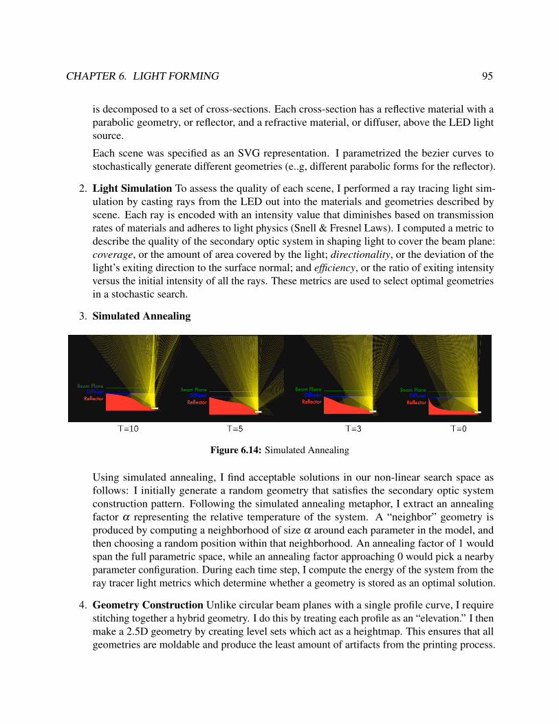
CHAPTER 6. LIGHT FORMING 95
is decomposed to a set of cross-sections. Each cross-section has a reflective material with aparabolic geometry, or reflector, and a refractive material, or diffuser, above the LED lightsource.
Each scene was specified as an SVG representation. I parametrized the bezier curves tostochastically generate different geometries (e..g, different parabolic forms for the reflector).
2. Light Simulation To assess the quality of each scene, I performed a ray tracing light sim-ulation by casting rays from the LED out into the materials and geometries described byscene. Each ray is encoded with an intensity value that diminishes based on transmissionrates of materials and adheres to light physics (Snell & Fresnel Laws). I computed a metric todescribe the quality of the secondary optic system in shaping light to cover the beam plane:coverage, or the amount of area covered by the light; directionality, or the deviation of thelight’s exiting direction to the surface normal; and efficiency, or the ratio of exiting intensityversus the initial intensity of all the rays. These metrics are used to select optimal geometriesin a stochastic search.
3. Simulated Annealing
Figure 6.14: Simulated Annealing
Using simulated annealing, I find acceptable solutions in our non-linear search space asfollows: I initially generate a random geometry that satisfies the secondary optic systemconstruction pattern. Following the simulated annealing metaphor, I extract an annealingfactor α representing the relative temperature of the system. A “neighbor” geometry isproduced by computing a neighborhood of size α around each parameter in the model, andthen choosing a random position within that neighborhood. An annealing factor of 1 wouldspan the full parametric space, while an annealing factor approaching 0 would pick a nearbyparameter configuration. During each time step, I compute the energy of the system from theray tracer light metrics which determine whether a geometry is stored as an optimal solution.
4. Geometry Construction Unlike circular beam planes with a single profile curve, I requirestitching together a hybrid geometry. I do this by treating each profile as an “elevation.” I thenmake a 2.5D geometry by creating level sets which act as a heightmap. This ensures that allgeometries are moldable and produce the least amount of artifacts from the printing process.

CHAPTER 6. LIGHT FORMING 96
Figure 6.15: Fabricated reflectors. A total internal reflection (TIR) reflector printing in clear resin (left).Light enters through an air cavity above the LED and is reflected internally, spreading light throughout thelens. A parabolic reflector printing in clear resin, with a coat of mirror spray and acrylic coating (right).
Fabricating Secondary Optic Elements. Once the digital modeling files are produced, they areprinted using various 3D printing techniques (Figure 6.15). In our case, a Type A FDM printer at0.1mm resolution was used for most luminaires. When higher quality reflection or refraction wasrequired, a Form 1+ SLA printer at 0.025mm resolution was used with clear resin. Resolution isan important factor since ridging artifacts from stereolithography can cause low-quality SOEs anduneven diffusion. Our pipeline alerts the user of luminaire quality issues when the LED density ofthe luminaire reaches a threshold above a reflector’s efficiency. Since 3D printing with reflectivematerials is currently not achievable with commercial digital fabrication tools, I created reflectivegeometries by spraying 3D prints with a coat of Mirror Spray (Rust-Oleum 267727). This provideda low-cost approach to achieving the desired reflectance.
Diffuser LayerDiffusers control the final presentation of light, scattering light with the goal of uniformly illumi-nating a space or surface. For many applications, a host of materials can act as diffusers, fromprofessionally-designed materials to ping pong balls and frosted acrylic. While a good diffuser isa key component to a successful luminaire, the effectiveness of a diffuser depends on the shapeof the light beam itself. For this reason, diffusers such as frosted acrylic require a large distancebetween the diffuser and light source to illuminate larger areas (see Figure 6.12, Spacer). Moreadvanced materials can diffuse light through refraction where light rays collide with material atomsand scatter.
Crafting Diffusers. I created a proxy-mediated fabrication technique (described in Chapter 5),or a human-in-the-loop pipeline that requires material engagement with the user. The role ofcomputational design in this pipeline is to provide an armature for working with physical materials.

CHAPTER 6. LIGHT FORMING 97
Heightmap(SVG Design) 40% GLASS – PDMS
2.5D Printed Mold(3 mm thick)
print cast
Figure 6.16: LED Diffuser
The diffuser fabrication technique leverages a maker-friendly PDMS silicone that can be usedto encapsulate different refractive materials. Our technique uses highly refractive glass spheres (thatare readily available in different sizes) commonly used to make reflective paint for roadways andsignage; they can be mixed into the PDMS at different sizes, combinations of sizes, ratios of glassto PDMS. The mold can be designed to have different thickness, non-uniform thickness, or leveragethe larger family of casting techniques (e.g., compression/press-molding).
The PDMS I used is TAP Platinum Silicone, a two-part 1:1 mixture which vulcanizes at roomtemperature. This silicone is especially forgiving for casting, readily removable from a cast forgeometries with deep undercuts or fine details without the need for a mold release coating. PDMSalso has good heat, chemical, and mechanical resistance properties and cures in 2 hours without theneed to use a vacuum. While it is flexible, it also offers high dimensional stability.
The glass beads used were Cole Products glass beads with a refractive index greater than 1.5.These beads were used in a variety of sizes (from 0.1 mm to 3.0 mm); the different qualities oflight interaction with bead size were explored in the example artifacts in the next section. AlthoughI used glass beads, a host of different refractive materials could be encapsulated by silicone andprovide different light interactions.
Characterizing Silicone-Glass Diffusers. To find the optimal mixture ratios, I doped disks (30mm x 3mm) with concentrations from 0% to 50% glass by mass mixtures in 5% increments6.Disks were also fabricated from Optigrafix Light Diffuser Film, 300 grit frosted acrylic. Diffuserdisks were each placed above a 10 mm spacer beam-shaper above a 1W LED (120 viewing angle).Each disk was photographed (18 mm f/11 1/100 sec) and applied a Gaussian smoothing filter. Pixelvalues were mapped to luminosity using the camera’s response curve. To extract the luminosityplot, the luminosity of each radius band was sampled and remapped to degrees from beam angle.To metrics were used to characterize the samples:
• Light transmission was calculated as the sum of luminosity values. The transmission rate wascalculated as the transmission of a diffuser over the transmission of the uncovered LED.
6 Mixtures with glass concentrations above 50% by mass suffered from curing issues.

CHAPTER 6. LIGHT FORMING 98
Relative Luminous Intensity
Deg
rees
from
Bea
m A
xis
0° 10° 20° 30° 40°
50°
60°
70°
80°
0.2 0.4 0.6 0.8 1.0
PLA ReflectorSLA ReflectorTIR ReflectorDiffuser OnlyControl: OptiGrafix FilmControl: Frosted AcrylicControl: Bare LED
Figure 6.17: Polar Luminous Intensity Graph. The diagram indicates the distribution of the relative luminousintensity of the luminaire. Control systems are marked with dashed lines. Each reflector condition has a 40%glass by mass 3 mm diffuser.
• Light diffusion was calculated as the standard deviation of the relative luminous intensityacross different viewing angles.
I found that 40% glass by mass-produced the highest diffusion and transmission rates.The final polar luminosity curves for each system are displayed in Figure 6.17. The luminosity
curves for secondary optic system elements notably show a more uniform distribution of light,redistribution the energy at the 0-10 range to the outermost viewing angles.
6.5 Luminaire CAD ToolOur luminaire design tool was designed for users familiar with vector graphics and built as a webapplication (Figure 6.18). The web application incorporates the computational design backendfor constructing secondary optic systems by allowing users to specify high-level luminaire designspecifications such as LED placement, LED color, and target areas for the LED to fill. The tooluses the paper.js vector graphics scripting framework [108] which enables common vector editingoperations and backwards compatibility with vector graphics applications.
Interactions. Users can then place, remove, and relocate LED elements anywhere in the scene.Geometries can then be created to interact with LED; users can specify whether paths block light

CHAPTER 6. LIGHT FORMING 99
Figure 6.18: Luminaire Creation Pipeline. a) Given an SVG graphic, our luminaire design tool aids userswith laying out LEDs, visualizing light interactions, and specifying target areas to fill with light. In thecallout, an LED is specified to fill a moon-shape. b) A computational design backend generates an optimalsecondary optics system to achieve the desired design using ray tracing to guide a simulated annealing search.All files for 3D printing geometries and milling circuits are produced by the backend, c) an instruction setguides the user to assemble the luminaire.
(hard edge) or allow light to pass through (soft edge). The user can also specify the color of theLED from a swatch panel. Otherwise, all interactions with the design take place in an externalvector graphic editor (e.g., Adobe Illustrator) in order to leverage user’s knowledge of and expertisewith existing graphic design tools. Depicted in Figure 6.19, I exposed different views to the user toprioritize different illumination aesthetic concerns.
Figure 6.19: Illumination views. Each view can be toggled by a user when composing their design toshowcase different illumination concerns. Each light source interacts with neighboring geometries and showslight interactions such as mixture and shadow creation.

CHAPTER 6. LIGHT FORMING 100
Simulated ViewsIn a construction view, users are provided a clear view of housing elements (e.g., placement ofnuts and bolts). This view allows a user to specify the shape to fill for each LED. In a compositionview, white rays are radially emitted from each LED and interact with geometries, displaying thedistribution of light in a scene as well as casting shadows when light blocking elements intersect withrays. An interaction view allows users to assign a unique color to track specific LED contributionsin the overall illumination. Lastly, a “lights-out” toggle controls the background luminance tosimulate a lit or unlit scene. In the composition and interaction views, the light simulation updatesdynamically to the different geometries or specifications of the design. A user’s knowledge oflight and its behavior is developed from direct manipulation of the LED – changing the quality ofworking with light to be more experiential.
Output. The design tools produces a set of 3D models for the enclosure, an SVG for PCB milling,a 3D model for casting a diffuser, and a 3D model for lenses (if specified). On fabricated, instructionsare provided for soldering LED components, assembling the final luminaire, and programming themicrocontroller.
6.6 Design Artifacts
Illuminated Hair Brooch
Figure 6.20: Illuminated Hair brooch (1 LED)
The sites in which we encounter LEDs are expanding; for sites like clothing and wearables,studies advocate a need for aesthetics that operate in the design space of ambiguity and slowness [38].To probe wearable light aesthetics, we designed an illuminated hair brooch (Figure 6.20). Assembledon a hair brooch, a single LED control layer was configured with a computationally-designed 3

CHAPTER 6. LIGHT FORMING 101
mm tall reflector holding a 2.5D crafted diffuser. The diffuser was cast at 40% glass-by-mass using150-micron glass spheres; the floral pattern consists of 1 mm and 3 mm thick geometries heldtogether by a common 1 mm thick PDMS substrate. Using relatively larger glass beads, the hairbrooch diffuser created a more complex light texture. As an exemplar of light as shadow creator,the different thicknesses of the diffuser geometries altered transmission rates, creating gradationsof intensity and casting shadows. These qualities match more of the complex texture of hair andclothing.
Sun Moon Glow Surface
Figure 6.21: Sun Moon Lightwork (25 LEDs)
The sun-moon glow surface is an ornamental piece designed to probe compositions with manyLEDs (Figure 6.21). Opposing the hard-edge matrix pattern, the sun-moon features a 32 LED non-matrix control layer, a 3 mm diffuser with 840-micron glass beads, and a computationally-designedreflector. As an exemplar of light as sharp and soft, the sunmoon reflector directs and shapes lightbeams from multiple LEDs to create soft edges (rays) and hard edges (moon segments). Althoughthe component LEDs in the moon shape are more distinguishable, the smaller ray areas demonstratethe effectiveness of reflectors for blending lights in small areas. Rather than one LED controllinga single area, the sun-moon demonstrates how multiple LEDs can be used to compose a largerillumination composition.
Tactile CityscapeThe tactile cityscape investigates interactive light surfaces. The cityscape is composed of a 16LED control layer with a reflector layer directing each LED to a building geometry. A diffuser iscomposed of a 2.5D cityscape, with building geometries ranging from 3 mm to 6 mm in thickness.These geometries are more pronounced versions of the light textures geometries. Instead, thesegeometries act as light-filling elements, giving a “body” to light. The 16 LEDs are programmedto change colors based on touch input, illuminating a path through the urban landscape. As an

CHAPTER 6. LIGHT FORMING 102
Figure 6.22: Tactile Cityscape (16 LEDs)
exemplar of light as space-filling, the cityscape used large volumes of refractive material to captureand fill geometries with light.
Dynamic Haptic Button
Figure 6.23: Haptic Button (1 Blue LED, 1 Green LED)
This haptic button probes reactive light surfaces. The diffuser is press-cast into a 5 mm domegeometry at 40% glass-by-mass (840-micron spheres) and positioned over a 1W LED. The dome,when deformed, produced dynamic diffuser geometries. The touch event is sensed with a capacitivetouch sensor and programmed with different lighting behaviors. As an exemplar of light as dynamicand reactive, the haptic button creates a multitude of rich light expression by making use of thedeformable diffuser actively reshaping and transforming the expression of the light beam.
User ArtifactsIn a workshop study described in Section 6.7, 11 pariticapnts designed luminaires ranging fromfigurative to abstract (Figure 6.24). Several participants motivated their design decisions to elicitsurprise, hiding elements in their design that would only be discoverable when power was supplied to

CHAPTER 6. LIGHT FORMING 103
Figure 6.24: Luminaires fabricated from user designs: (top) simulated results from the luminaire design tool,(bottom) the final physical luminaire.
luminaire (Participant #150, Participant #179, Participant #163, and Participant #199). Othersused the design task as a sandbox, for example, using a Venn diagram to explore color interactions(Participant #134). Overall participant’s assessment of their experience is summarized in Table6.2. In particular, participants associated their perception of creative freedom with the tool (4.3) totheir familiarity with design patterns developed through previous experience with Adobe Illustrator.
Creative Freedom Object Quality Agency
Rating (out of 5) 4.3±1.0 3.9±1.2 4.3±0.7
Table 6.2: Qualitative Assessment Luminaire Design Tool and Fabricated Luminaire Objects. Responses aresemantically anchored on a 5-point Likert scale, positive responses = 5.

CHAPTER 6. LIGHT FORMING 104
6.7 Workshop EvaluationWe invited 11 participants to take part in a workshop study designing their own luminaires. Themain goal of this user study was to obtain qualitative feedback on how the design tool facilitatedluminaire design. We were especially interested in understanding a user’s mental model of light andhow the Crafting Proxy would elicit material encounters. The questionnaires, interview guides, andstudy protocols used in this study are available in Appendix C.
ParticipantsA total of 11 participants were recruited from university mailing lists in Art, Architecture, andDesign. The average age of participants was 22 ± 3 (7 female, 4 male). Participants were selectedbased on self-reported expertise with vector graphic design and SVG editors and previous exposureworking with LEDs. A majority of users reported limited experience with 3D printing or digitalfabrication tools.
ProcedureEach user participated in a 1-hour workshop and 30-minute follow-up interview and was compen-sated $40. Each session resulted in a completed luminaire which was given to the user.
Workshop. Each workshop consisted of an electronics background questionnaire, a showcaseof luminaires, a diffuser ranking task, a design tool tutorial, and a 40-minute design task. Eachparticipant was tasked with creating a luminaire graphic with 5-7 LEDs not to exceed a 5" x 5"area. Participants were also asked to reflect aloud on the example luminaires, the design tool, andtheir design process. Due to fabrication time limitations, each luminaire was fabricated by theinvestigators after the workshop; some degree of experience is needed to solder surface mountcomponents, although components are relatively large (>5mm) and with practice hand-solderable.Additional steps were taken to demystify the process during the follow-up.
Follow-up. After the luminaire was constructed, participants were invited back to reflect on thefinal design. To avoid black boxing the process, participants were given a tour of the fabricationmachines and provided an explanation of the materials and techniques involved in producing theirluminaire. We asked users a series of questions regarding their experiences with the design tool, aswell as the final fabricated devices.
6.8 ResultsAll participants successfully completed their designs; some designs are represented in Figure6.24. We first report survey responses, then present qualitative results from participant interactionswith the luminaire design tool during the workshop, and finally discuss interview responses once

CHAPTER 6. LIGHT FORMING 105
participants received their fabricated luminaires. We synthesize these findings into common themesand insights for designing Crafting Proxies.
Survey ResultsIn our survey, participants reported experience with through-hole component LEDs, while a fewhad interacted with addressable LED strips. The majority of users (8 of 11) had not worked withsmart LEDs.
Barriers of Entry to LED Design
Prior to being introduced to our tool, users described their projects involving LEDs in simple, binaryterms. Their LEDs were used for behaviors like flashing and fading. Even for more hardware andsoftware-proficient users, the language used to talk about light was limited to the binary “on/off.”Other difficulties included hardware-to-design translation issues, especially in more complex designslike arranging LEDs in a circle:
Participant 170: I remember it being tricky to address the LEDs . . . we wanted thelevel of the circle to go up . . . there was endless debugging with the strips.
Users cited the cost of smart LEDs and the difficulty to program complex behaviors as theprimary barriers to LED usage.
Perceptions of the LED Aesthetic
Functionally, participants reported that LEDs used in personal projects were mostly used to indicatestatus. Aesthetics was the principle reason limiting LEDs to this specific use case. A majority ofour participants mentioned that the aesthetics of LEDs, even in strip form, were unpleasant, andphysically painful: “they hurt your eyes if you look directly at [them].” Users universally criticizedthe “characteristic look” of LEDs and how their overpowering presence and salience in designsforced their user to focus on the mechanics of the light rather than the design or overall experience:
Participant 160: You look at them, and you think “those are LEDs.”.. I don’t like thecharacteristic look of LEDs. And I don’t want to look at something and go “there’s anLED inside that’s making that light up.”
Participants also described uncertainty relating to how their designs would appear in the finalstate, having difficulty prototyping and testing out various options:
Participant 169: Sometimes LEDs just don’t look that good. It’s hard to know whatthey’re going to look like to the user . . . I’d love to make something that just diffusedall of the lights together so that I could make a really nice transition between colors.

CHAPTER 6. LIGHT FORMING 106
One participant so disliked seeing the mechanics of the LEDs that she took the opportunity todesign in physical barriers to her luminaire to obfuscate the light source (Figure 6.24 #134), optingfor an edge/rim light that emphasized the silhouette, despite the fact that our luminaires have built-indiffusers:
Participant 134: [I don’t want to] have that effect of seeing that bright LED directly. Ifeel like [seeing the LED underneath] reveals too much about how it functions.
Many participants never considered placing anything over the LEDs to affect the production oflight. Some had attempted maneuvering around the bright lights by diffusing them with opaque orsemi-transparent sheets, a plastic enclosure, or pre-fabricated lampshades. Despite strong negativeexperiences, users quickly warmed to the illumination aesthetic of the showcase luminaires:
Participant 179: It’s very aesthetically pleasing. And I like . . . the blend of colors thatgoes through it. It kind of reminds of seeing cities at night.
Workshop ResultsExpanded Vocabulary Mirrors New Understanding
In our tool workflow, participants had to create and annotate their design geometries in an externalvector graphics editor. Once a base design was created, our tool would load their graphics andapply treatments to more clearly indicate physical and conceptual geometries. Participants did havedifficulty conceptualizing these distinctions in the abstract; however, direct manipulation of lightsources grounded their mental model of how the design tool worked:
Participant 170: I’m thinking about the way the light is going to work. I wanted todefine shapes, and I wanted to play with where the light was going to be placed.
One assumption we made was that participants would prioritize an arrangement of LEDs suchas to produce a diffuse luminaire. However, for some, the light ray interactions became a formalelement to consider. One participant investigated placing in an arrangement that would create newshapes and forms from shadow and color interaction.
Participant 179: There might be some leakage if the rays intersect [geometries] at aninteresting angle.
This approach exposed the positive and negative spaces that arose from the shadows createdfrom different geometries. As users gained familiarity with the new capabilities afforded by thetool, they frequently returned to edit their base vector file, further developing their understanding ofwhat effects their choices would have, and beginning to conceptualize light as a craft material:

CHAPTER 6. LIGHT FORMING 107
Participant 170: I’m noticing the other shape that you made, these sides were different,so I could direct it to this edge, or this edge only. Instead, I’m kind of diffusing itthrough the whole thing. I want to make one edge that encapsulates the shape but thenalso allows me to direct the light wherever I want.
For expert illustrators, the largest amount of design time was spent on examining light interac-tions with geometries. We saw different light aesthetic concerns arise from the different simulatedviews. The composition view influenced more thinking around light decay/falloff.
Participant 169: Also you can see a difference in the light intensity based on howconcentrated the light beams are. I’m surprised that the light spreads so clearly in this[white ray view].
whereas the interaction (colored ray) view elicited more thinking about blending and LED colorinteractions:
Participant 170: A second ago, the light was down here, and it was covering morespace, but it wasn’t really blending. So it’s helpful to see that there might be someblending up here if I put the light up here. . .
Participants verbalized a new consideration of the physical factors of the LED. A shift invocabulary reflected this new understanding of the aesthetic potential of light. All participantsconceded they had never really thought about light interactions before, and the tool represented anew engaging type of thinking that they were eager to pursue in future designs.
Followup ReactionsIn the follow-up, participants shared a new awareness of LEDs in their daily life. Diffusion was aparticularly salient trait that began to take form in new design projects.
Participant 134: I’m trying to make a tube of light . . . I was thinking about what kindof considerations I have to make to get the light to spread all around.
Even participants sensitive to the LED aesthetic were motivated by the diffusion of theirluminaires:
Participant 134: I previously hadn’t even thought about incorporating LEDs, but nowI’m thinking about how we might incorporate LEDs to make things more user-friendly.
Expectations from the tool’s simulated results and the final physical luminaire formed a hardcontract with user’s end perception of the tool. Notably, participants were satisfied with the fidelityof the tool to the fabricated design results of their design (3.9). Specifically, users respondedpositively to the texture and flexibility of the diffusers. Users were intrigued with the way thetool allowed emergent shapes to appear and expressed interest in the construction process. Somephysical luminaires failed to meet expectations:

CHAPTER 6. LIGHT FORMING 108
Participant 179: I can’t really tell the different shapes that were initially in the design. . . besides the hard, sharp boundaries. It is interesting [that] these cut off on each othera lot harder than I expected, like the yellow meeting the blue there’s a sharp line ofcontrast – I thought there would be more of a mixing zone.
Despite this, participants reported feeling agency (4.3) to integrate their designs into moredomain-specific projects upon understanding the limitations of the tool.
Renewal of Light as a Craft Material
Participants began to consider light as a material over which they could wield control. Usersemphasized blending and mixing of colors to achieve novel effects and indicated a desire to“paint with light,” rather than simply add LEDs:
Participant 160: I’ve never even tried blending LED colors together, so this facilitatesa little more advanced thinking: I don’t want to just use LEDs separately; I want toblend them together to use color effects and make them brighter.
The tool allowed users to rapidly prototype their concepts, visualizing how the final piece wouldappear with the LEDs in place. Users readily incorporated soft and hard edges, mixing colors, anddelineated conceptual boundaries in their designs; users expressed a desire to play around with thetool more and discover new light interactions.
Participant 169: I’d play around more with hard edges and soft edges, to see if I couldget some nice mixing. I’d love to see how the color is actually changing and change itwith more intention.
6.9 DiscussionAlthough this work discusses, explores, and expands the role of light in design, I see these insightsand principles guiding the design of future materials and tools for hybrid making.
Light CompositesIn this work, I explored how applying the compositing design pattern for an immaterial likecomputation might be applied to another immaterial like light. Compositing requires a tightcoupling between a physical material that activates and makes visible changes to the immaterial.As referenced in Chapter 4, Daniel Rozin’s Wooden Mirror couples the immaterial camera sensormatrix to wooden taxels, allowing the pixel to come into expression. From our synthesis of theconversational profile with light, I observed that ways material practitioners work with light isheavily influenced by its interactions with other refractive, reflective, and opaque materials. Thisreliance the secondary materials to shape and manipulate light echoes the role of the physical proxyin composites.

CHAPTER 6. LIGHT FORMING 109
Expanding the Light RepertoireThe demand for an expanded LED aesthetic is present and growing. As flexible electronics develop,LEDs are being into wearable applications, whether integrated onto tattoos [117], or embeddedin clothing. In its most subversive role, low-cost LED “throwies” [166] have gained traction asurban graffiti. However, I saw a tension manifest in a common critique that LEDs (and electronics)in design are overpowering, distracting from any other elements. On the other hand, this saliencyhas been largely leveraged by interaction designers to engage and captivate audiences. Often, this“tacking on of media” [137] limits the exploration of the physical design space to instead focus ondesigning through digital manipulation. This line of thinking aligned with the mental model andLED interaction patterns of participants in our workshop.
Through light compositing, I saw how material-centric investigations could expand the electro-aesthetic and yield diverse light forms that capture a larger subset of the light’s material profile. Idemonstrated how facilitating the interaction between the physical proxy and the immaterial can bea site for computational design. Leveraging established practices using secondary optic systems tomanipulate and shape light; our computational design routines allowed for participants to explorea wider range of interactions. The conversational profile framed how each routine (the controller,beam-shaper, and diffuser) could be composed to support and expand light behaviors and form.
Through the use of reflectors, light was focused and redirected to have sharp and soft surfaceinteraction (Figure 6.21). Tactile diffusers made from PDMS silicone and glass beads accessedthe repertoire of 3D printing, casting, and mold making techniques. By changing the thickness ofdifferent areas of a diffuser, gradations of light and shadow were used to support light as a shadow-creator (Figure 6.20). In building large volumes of diffuser material, the workflow supported lightas form-filling (Figure 6.22. Using a compression mold, a tactile dome diffuser allowed for thediffuser to change shape and leverage light as a reactive material. By changing the size of therefractive glass bead in the diffuser, these diffusers also formed a new illumination aesthetic — lighttextures.
Lastly, by introducing a trace assistance algorithm, I saw participants create luminaire designsthat broke the traditional forms of the grid and strip (Figure 6.24) and decoupled the influenceof electronic and computational actors on these light forms. In the workshop study, the shift invocabulary towards thinking of light as a painterly material further indicates the effectiveness ofcasting light as a craft material.
Supporting a Material EpistemologyBlackboxing and Simulation. In many engineering practices, a common method of working withthe complex interactions of various materials is via black boxing. Blackboxing compartmentalizesknowledge into systems made of components with inputs and outputs, removing the need tounderstand the inner workings and instead allowing more complex and sophisticated systems todevelop. As a byproduct, many immaterials are found as readymade components, parts, and systemsthat abstract away the intricacies of working with the raw element and relaying physical cues

CHAPTER 6. LIGHT FORMING 110
important for material workflows. The LED is an example of a manufacturing blackbox where theindividual components shaping light are not part of the API that practitioners encounter.
While blackboxes lower the barrier to entry, there is little in building exploratory engagementwith a material. I saw this behavior in how workshop participants their restricted view of theLED aesthetic and its role as a status indicator. This lack of exploration is a reoccurring themein educational makerspaces and emerging digital fabrication practices, where laser cutters turninto keychain factories [18] or where only a small subset of the population contribute to newdesigns [139]. Our tool, while maintaining compartmentalization of computational design routines,leveraged the SVG as a method to specify more open-ended inputs. Like many CAD tools, thegeometries were in conjunction with a simulation engine to provide the user with informationabout the behavior of the design. I showed how enabling real-time simulation of how light behaveswith different geometries allows users to have a material encounter with light. The feedback fromthe simulation actively factored into how users explored different designs, but also in the waysthey constructed knowledge of light and its behaviors. Furthermore, the different rendering styles,whether only viewing intensity or viewing color interaction, allowed users to focus on uniquedesign concerns through an experiential encounter with light. While maintaining the benefits of theblackbox, material simulation was a powerful technique to also communicate internal workings andsupport a material epistemology.
Figure 6.25: Participant 170 - Owl Luminaire
Integrated Workflows. One principle for creative thinking is to support open interexchange, orthe ability for multiple tools to seamlessly inteoperate [160]. As described in Chapter 9, I leverageda Support Vector Graphics (SVG) synchronized between an SVG editor and a web applicationusing the vector graphics library paper.js. I saw the benefits of this behavior in seasoned users ofSVG editors like Adobe Illustrator (e.g., Participant 170’s Owl Luminaire) that leveraged vectorgraphic thinking, a way of decomposing and building forms with boolean shape operations, with thefeedback from the light ray simulation to iterate on complex geometries that used light as a graphicelement. I see these details in how the participant chose to place the LED in the stomach region ofthe owl off-center. This allows a gradient to form that works similar to a highlight vector commonly
CHAPTER 6. LIGHT FORMING 111
used in graphic design. While the synchronized SVG achieved interoperability, it also allowed for adifferent material epistemology to cognitively bias the creative direction of the luminaire.
LimitationsOur study demonstrated that in engaging with a material-centric workflow and expanded creativerepertoires in the confines of a short hour-long workshop. Many users desired to continue iteratingon their design, but many more aimed to start fresh, knowing the full capabilities of the tool andfabrication method.
In the design tool, participants engaged in the material manipulation of light through digitalsimulation (rendering and raytracing). However, due to fabrication time, users did not participate inthe physical making of the displays and preventing exposure milling the circuit board, casting thediffuser, or applying reflective spraypaint to the 3D printed reflector geometry. I anticipate thesematerial encounters would enhance participant’s creative repertoire to, for example, deviate from theglass beads used as the refractive material in diffusers to experiment with doping different materialin the PDMS silicone. The process walkthrough in itself clarified many participant’s mental modelsof the LED that were readily being applied to active, creative projects.
Our fabrication technique, although bound by bed size, results in a final cost of 5" x 5" displaycomponent with 10 LEDs in the $6-7 price range; as a standalone device, logical control and powerbring the cost to $12. I showed that I can generate geometries that more effectively diffuse a pointlight across a shape. Study participants all confirmed that design opportunities well deserved thecost; many cited access to fabrication facilities as the main issue to adoption.
In this work, I described an approach for designing light emitted from the more ubiquitous andlow-cost LED. Our technique, however, needs at least (5 mm) above the light source to be effective.I envision our tool as supporting a wider ecology of materials, including electroluminescence (EL)wire and panels, and organic polymer LEDs [220], to foreground the physical design of light ininteractive devices, wearables, and urban architecture. I see our technique used in conjunctionwith light pipe structures that can transport light more efficiently that could reduce the footprintcurrently required to illuminate luminaires with large surface areas and complex geometries (i.e.,twists-and-turns). Current 3D printing resolution still introduces artifacts into fabricated lenses;an efficient transfer of light would be possible with smooth and optically-clear surfaces; however,I found aesthetically acceptable results using SLA printing techniques. As printing resolutionimproves, I foresee our tool as a preliminary step to designing custom non-imaging secondary opticsfor illumination design. While our current method requires assembly of different fabricated parts,our 2.5D approach is portable to multi-material stereolithographic printing, especially as opticallyclear and reflective materials become available for these processes.
Future WorkWhile this work explores light’s properties of diffusion, several opportunities exist for expandingIllumination Aesthetics. For instance, more advanced optics geometries such as side-emission or
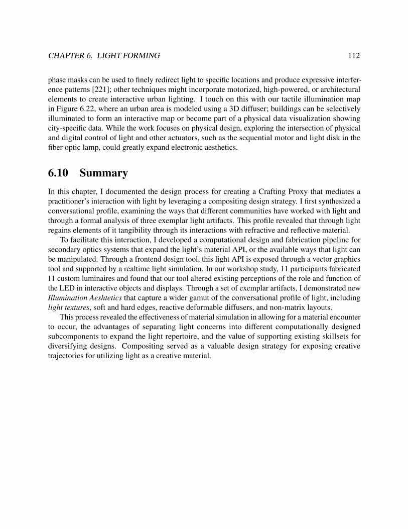
CHAPTER 6. LIGHT FORMING 112
phase masks can be used to finely redirect light to specific locations and produce expressive interfer-ence patterns [221]; other techniques might incorporate motorized, high-powered, or architecturalelements to create interactive urban lighting. I touch on this with our tactile illumination mapin Figure 6.22, where an urban area is modeled using a 3D diffuser; buildings can be selectivelyilluminated to form an interactive map or become part of a physical data visualization showingcity-specific data. While the work focuses on physical design, exploring the intersection of physicaland digital control of light and other actuators, such as the sequential motor and light disk in thefiber optic lamp, could greatly expand electronic aesthetics.
6.10 SummaryIn this chapter, I documented the design process for creating a Crafting Proxy that mediates apractitioner’s interaction with light by leveraging a compositing design strategy. I first synthesized aconversational profile, examining the ways that different communities have worked with light andthrough a formal analysis of three exemplar light artifacts. This profile revealed that through lightregains elements of it tangibility through its interactions with refractive and reflective material.
To facilitate this interaction, I developed a computational design and fabrication pipeline forsecondary optics systems that expand the light’s material API, or the available ways that light canbe manipulated. Through a frontend design tool, this light API is exposed through a vector graphicstool and supported by a realtime light simulation. In our workshop study, 11 participants fabricated11 custom luminaires and found that our tool altered existing perceptions of the role and function ofthe LED in interactive objects and displays. Through a set of exemplar artifacts, I demonstrated newIllumination Aeshtetics that capture a wider gamut of the conversational profile of light, includinglight textures, soft and hard edges, reactive deformable diffusers, and non-matrix layouts.
This process revealed the effectiveness of material simulation in allowing for a material encounterto occur, the advantages of separating light concerns into different computationally designedsubcomponents to expand the light repertoire, and the value of supporting existing skillsets fordiversifying designs. Compositing served as a valuable design strategy for exposing creativetrajectories for utilizing light as a creative material.

113
Chapter 7
Heat Forming
Unlike computation, light, or electricity, working with heat is more complicated since it reacts to ortriggers reactions more slowly making it difficult to control (e.g., hysteresis, power) and perceive(e.g., thermoreceptor fatigue)1. Controlling heat is much more nuanced, and when producedelectrically, the high current needed can also quickly become a safety concern.
As an immaterial, heat is useful for understanding the boundaries of a compositing strategy.Our focus in this chapter is to design a Crafting Proxy that acts as a mediator and lens to heat,foregrounding the behaviors, forms, and structures of heat in material-driven practices and the waysthat heat-centric workflows are complicated by heat’s immateriality. I review how heat is used inpractice and the variety of Thermoreactive Composites (TrCs) — assemblages of heaters, substrates,and thermoreactive materials — that exist across HCI including thermoreactive painting [143],thermoreactive sculpture [68], thermoreactive wearables [98], and thermoreactive clothing [38]’.
Heat is most limited by the means in which to control it, however, the ability to produceheat (via resistive heating) makes it an incredibly versatile material. Only requiring a conductivematerial and power supply, resistive heating can be used to produce heat in a variety of form factorsincluding conductive thread, paint, ink, tape, and more. Through computational design techniques, Iexpand the available expressions of resistive heating to foreground heat as a spatiotemporal mediummedium.
To account for challenges to perception and cognition, I introduce a perceivability design stagethat specifically explores ways of mapping the output of the physical stimuli (in this case heat) tothe psychophysics of the human body, acting as a lens for the body to perceive heat interactions andcommunicate the interconnectivity of electricity, heat, and thermoreactive materials.1 Elements of this chapter were previously published in: Cesar Torres, Jessica Chang, Advaita Patel, and Eric Paulos.
“Phosphenes: Crafting Resistive Heaters Within Thermoreactive Composites.” In: Proceedings of the 2019 onDesigning Interactive Systems Conference. DIS ’19. San Diego, CA, USA: ACM, 2019, pp. 907–919. DOI :10.1145/3322276.3322375.

CHAPTER 7. HEAT FORMING 114
7.1 IntroductionPhosphenes is a Crafting Proxy that aids in the making of Thermoreactive Composites (TrC), a classof objects composed of a thermoreactive element and a heat-generating element (Figure 7.1). TrCsis a design pattern used to expose heat and its interactions with other materials as an experiential"conversation" that introduces, adjusts, and satisfies circuit requirements during the act of making.
Figure 7.1: A Thermoreactive Composite. Thermochromic pigments are bound in gum arabic, giving itmany of the same qualities as watercolor paints. A purple thermochromic glaze is applied to a chromostablewatercolor composition depicting an apple. A silver ink resistive heater is coupled to the composition withKapton tape; when triggered, it produces a dynamic ripening-apple illustration.
Crafting with resistive heaters, or supporting a material epistemology outlined in Chapter 2, isenabled in three ways:
1. Facilitating a material encounter through an iterative design practice through a maker-friendlyfabrication pipeline that captures a composition, facilitates resistive heater design, and debugsand validates fabricated heaters.
2. Communicating the creative constraints between different conductor, power supply, andthermoreactive material combinations while maintaining electrically-valid and power-safedesigns.
3. Expanding the malleability, expressivity, and composability of electrical heat through compu-tational design algorithms that allow resistive heaters to activate specific areas of a thermore-active composition at different times.
4. Exposing a live thermoelectric circuit model using responsive visual annotations, embodieddesign interactions, and responsive heat visualization (using commodity thermochromic liquidcrystal [TLC] sheets).

CHAPTER 7. HEAT FORMING 115
7.2 Related WorkEmerging practices have used thermoelectric heating elements in a variety of form factors includingPeltier elements [144] and resistive heaters from conductive thread [39, 98], silver ink [68, 219],and gold leaf [97]. Heating elements have been coupled with a variety of thermoreactive materialsincluding gels [96, 128] and thermochromic pigments or liquid crystals [177] suspended in carriersthat bind to paper, films, and threads.
In multimaterial-layer constructions, the thermal properties of materials have been used asactuation mechanisms [140, 47, 76, 204], as a 3D-forming technique [68, 6], as a sensing technol-ogy [2], or as a trigger for secondary effects (e.g. humidity [219]). Jonsson et al. [93] exploredthe somatic experience of heat and the different aesthetics that can be formed from leveraging theambiguity of thermoception (e.g., subtleness; subjectivity) or the way heat interacts with materials(e.g., inertia, heat transfer). I add to these expanding practices and contribute a workflow thatbolsters explorations with heat and thermoreactive materials through a faster, expressive, and moreiterative practice enabled through silver inkjet-printed resistive heaters.
Resistive Heater Design and FabricationAs a fabrication strategy, many resistive heating applications etch or mill copper plates or use copperwire coils. Resistive heaters have been embedded within existing material practices; Devendorf etal. [39] demonstrated that weaving conductive thread into knitting patterns can also be used to createdifferent heat profiles. Recent advancements in silver ink printing allow for more user-friendly,fast, accurate, and effective prototyping techniques for resistive heaters [101]. Within silver inkcircuit design, LightTrace [183] utilized the non-negligible resistance introduced by silver-inktraces to regulate current sent to LEDs and computationally adjusts the resistance by altering atrace’s width or length. Phosphenes similarly incorporates circuit design patterns to control thepower generation rates of resistive heaters but incorporates a spatial dimension to constrain heatdistribution to user-specified areas and introduces a temporal dimension by assembling multipleheaters with different heat generation rates in parallel.
Circuit Design ToolsCircuit design tools have explored increasing the perceivability of electricity in circuits [13].Toastboard, an instrumented breadboard, allowed users to verify electrical connections and preventslips [43]. Bifröst [125] provides support for embedded system debugging; in a similar initiativeboth Bifröst and this work aim to increase the perceivability of electronic components; however,I take a material-centric approach in order to support users without electronics domain-expertise.Our prior work explored design tools that acknowledge the unique resistivity and constructionchallenges of working with conductive ink, thread, paint, and tape to explore and express LEDcircuit drawings [118]. Phosphenes similarly supports a variety of thermoreactive materials as wellas circuit conductors.

CHAPTER 7. HEAT FORMING 116
7.3 Conversational Profile
Generating HeatTo generate heat, many applications use a technique known as joule or resistive heating, a processwhere electrical current I is converted into heat when electrons collide and transfer energy to con-ductor atoms [186]. Working with resistive heaters can be decomposed into two major components:(1) regulating an electric current that determines the heater’s power, (2) controlling how heat movesthrough space via thermodynamics (diffusion, convection, radiation).
The heat generation rate, or power, is specified in watts is the product of current I and voltageV . These designs often employ space-filling curves, such as this serpentine pattern, to efficientlydistribute heat.
Working with Resistive HeatersIn practice, connecting a resistive heater to a variable power supply and dialing in the input voltageis enough to configure a heater properly. Through trial and error, the heating rate can be adjusted toactivate a thermoreactive material. Many commodity hobbyist heaters distribute heat over a smallrectangular space; while a limited heat profile, many heaters can be composed side-by-side to heatlarger and more varied spaces. This results in many thermoreactive composites having heat triggera global binary on/off change (e.g., triggering a black thermochromic mask to disappear to reveala hidden message) rather than leveraging more of heat’s interactions with other materials and itsrespective behaviors and forms.
Constraining heat to a specific area requires custom resistive heaters or custom heat sinks, thelatter of which would require expensive metalworking. Resistive heaters, on the other hand, can bemade from conductive thread, copper wire, or silver ink and follow a similar construction pattern:in knowing the amount of power that needs to be generated (P = IV ), the resistance of the heatercan be determined (R = V 2/P). There exist a number of ways to cut thread, mill copper, or laysilver ink to satisfy the necessary resistance, but it will dramatically affect how heat is distributed.The most efficient heaters use wire forms in serpentine lines, also known as meandering lines, orother space-filling patterns to distribute heat evenly. For many wearable applications, the limits ofthe power supply (e.g., a lithium-ion battery) heavily constrains the power generation rates that arefeasible. Controlling more than one heater at a time requires a microcontroller and special currentcontrol electrical components (e.g., h-bridge, BJT transistors) that adds significant complexity and alarger footprint (detrimental to many wearable applications).
In this process, the resistive heater, thermoreactive material, and power supply introduceseveral complex constraints that (1) limit the designs that can be made, (2) restrict the level ofengagement with heat to a binary on/off, (3) are imperceivable when working experientially withthese components.

CHAPTER 7. HEAT FORMING 117
7.4 Composability: Spatiotemporal Resisitive HeatersIn this section, we describe a computational design algorithm for designing resistive heaters toactivate Thermoreactive Composite.
For many application, joule heater design is based on two parameters. The conductive materialproperties and power supply. However, when configured in a Thermoreactive Composite, theheater must also be configured to the specific thermoreactive material properties and thermoreactivecomposition. For example, when powered by a 5V power supply, a 50 Ω heater generates abouthalf a watt of power. When a cloth silkscreened with liquid crystal, a thermoreactive material thattakes about 12 J to activate, is placed on top of this heater, we can expect to see a color transition inabout 20 seconds (Figure 7.2).
Unlike common heater designs, our algorithm introduces a temporal component allowing usersto selectively control which areas of a composition activate over time. The core insight is that eachresistive heater is a collection of sub-heaters, connected in parallel to form a current divider circuit.Thus, the ability to control how much current is flowing over selective regions of a circuit allowsus to control the activation times of thermoreactive materials. The TrC interactions described inthis work are largely driven from the goal to activate a target area of the thermoreactive materialwithin a certain period of time (rise time t) driven by a common power supply with nominal voltageVS. In order to ensure safe operation, the power of the circuit is capped at the power rating of theconductive material and power supply.
Heating specific regionsLet a heater by modeled as a collection of n resistors Ri connected in parallel. Each resistor isdesignated a corresponding area Ai to heat up. In this configuration, each resistor i generates powerPi following Kirchhoff’s Circuit Laws:
Pi =V 2S /Ri (7.1)
When connected in parallel, resistors share a common input voltage source VS and therefore donot introduce a voltage drop that affects other resistors. This allows each heater’s power to beindividually controlled by changing its resistance.
For silver ink (thickness d, and resistivity ρ), resistance can be controlled by either changingthe trace length l or width w of silver ink heaters as follows:
R = ρl
dw(7.2)
To fill a specific area Ai with a serpentine pattern (A = wl)2, the width of the trace can becomputed as follows:
w =
√ρAi
dRi(7.3)
2 A conductive material with a small cross-section (i.e., wire) can be used to maximize current flow and localizeheat over an area or volume; common patterns include serpentine (e.g., space heaters, radiators) and spiral patterns(e.g., stove heating elements).

CHAPTER 7. HEAT FORMING 118
Heating at specific timesSince a heater is composed of resistors connected in parallel, a current divider circuit is created(Figure 7.3) allowing us to specify the power generation rate of different areas by adjusting theresistance Ri. The power rate Pi to activate the thermoreactive material at time t is calculated as:
Pi =Ea
t(7.4)
where Ea is the activation energy of the thermoreactive material (calculation: Figure 7.5, table:Figure 7.6).
Making a HeaterAs an example, we describe the interactions for creating a Thermoreactive Composite "progressbar"(Figure 7.3). The composite is composed of a silver ink heater inserted into the cuff of a sleeve.The sleeve has a liquid crystal design screen printed onto the cuff. The heater is designed such thatwhen current is supplied to the heater, it will activate the liquid crystal (Ea = 12J) pattern from leftto right over the course of a minute.
Figure 7.2: Parameters of a Thermoreactive Composite - The power supply and silver ink circuit are usedto form a joule heater. This heater is inserted into the cuff of a sleeve with a screenprinted thermoreactivedesign made with liquid crystal paint.
Given the above set of TRC parameters, a user draws a rectangular region (per the dimensions ofthe cuff design) on the digital canvas. Using a subdivision widget, the user splits this region into fivesubregions in order to assign each region a different rise time. A scale describes the relationshipsbetween rise time and power (Equation 7.4), assigning an identifying color to each combination.Colors are chosen on the thermographic scale - warm-colored regions (i.e., towards red) produceheat and faster rates than cool-colored regions (i.e., towards blue).

CHAPTER 7. HEAT FORMING 119
Figure 7.3: Designing Heat Regions and Activation Times. A user draws an initial heat region (per thedimensions of the cuff design), subdivides the region into 5 using a widget, and specifies desired activationtimes. A computational model updates and computes the power specification.
Notably, the time-power scale does not allow parameters that would allow unsafe heating rates(2.0 W max, 6 s quickest rise time). The user specifies a target rise time for each region of theprogress bar; internally, a circuit model updates the target power, queries respective current drawsfor each sub-heater and calculates the trace width to generate a serpentine pattern with the ability tocover the target area.
Figure 7.4: Trace Design. Circuit design variables are queried from the circuit model for each heat regionand a serpentine pattern is generated, specific to silver ink, to achieve the target resistance and power.

CHAPTER 7. HEAT FORMING 120
Figure 7.5: Characterization Routine.
Characterizing a New MaterialSince the landscape of thermoreactive materials is rapidly evolving, we use the following charac-terization routine to determine the activation energy Ea of an unknown thermoreactive material,substrate, and joule heater configuration. For instance, while we know the activation material ofthermochromic PLA with a 3 mm wall, this value would be more sensitive if compositions weremade with thinner geometries.
To characterize a TrC combination, only a sample of a thermoreactive material on a targetsubstrate, a heater with known power P, and a stopwatch are required. The routine follows:
1. If the power of the heater is unknown, then connect the heater to a power supply and apply anominal voltage VS. Measure the current draw I calculate power as (P =V I).
2. Attach the thermoreactive material and substrate (in the same way it will be used) to theheater, e.g., using double-sided tape or thermal epoxy.
3. Record a start time t0 and power on the heater. Observe the thermoreactive material until a JustNoticeable Difference (JND) is detected and log the time t f . For thermochromic materials, aJND refers to a color change. For thermo-programmable materials, a JND refers to a changein motion. Use the following formula to calculate the activation energy:
Ea =P
t f − ti

CHAPTER 7. HEAT FORMING 121
The activation energy captured by this routine represents a lower bound for activating the thermore-active material, which only needs to be calculated once. The routine is limited by the assumptionthat the heater will be activated in the same environmental conditions (e.g., room temperature,starting from steady-state). It also considers a negligible convection factor (e.g., a breeze blowingon the composite). Our experiments with thermochromic materials yielded the following activationenergies:
Figure 7.6: Activation Energy of Various Thermoreactive Composites
For thermochromic PLA filament, the routine was carried out for wall thicknesses from 2millimeters to 10 millimeters. The resulting values were fit with an exponential model and yieldeda regression coefficient of 0.9755, indicating a strong fit and predictive power. For materials thatrequire an activation energy greater than 1kJ, we anticipate the exponential behavior is a result ofthe temperature differential between the environment and the thermoreactive material introducing asignificant cooling term.
7.5 Resistive Heater CAD ToolPhosphenes is a Crafting Proxy that aids a user in designing a resistive heater specific to a thermore-active composition. The process uses silver-ink inkjet printing in order to create flexible resistiveheaters on a PET substrate. To enable this workflow, I incorporate the composability mechanismsfor composing heat described in Section 7.4 and perceivability mechanisms for exposing materialcues in Section 7.6.
Creative Environment ConfigurationThe creative environment is composed of a tablet running design software and a network connectedprinter and camera. All components of the creative environment, unless otherwise noted, cancommunicate with each other via the WebSocket framework described in Chapter 9.
A resistive heater CAD tool was programmed as a paper.js web application that runs on a tabletconfigured on a gooseneck stand. This tablet can be moved and positioned hand-free throughout thecreative environment.

CHAPTER 7. HEAT FORMING 122
An IPEVO document camera is configured to capture images of objects placed underneath andsend these images to peripheral devices. The image data also contains the focal distance in order toconfigure accurate measurements with the image.
An Epson ET-2550 EcoTank printer is connected via Bluetooth to the tablet. The printer isconfigured with the AgIC silver ink system [3].
WorkflowThe thermoreactive composite workflow consists of three stages:
Configuration Stage. In this stage, users specify the materials being used in the thermoreactivecomposite; a library of common conductors, power supplies, and thermoreactive materials allow forquick parameter selection; for parameters like the activation energy of a thermoreactive material Ea,I provide a walkthrough tutorial that describes the process of empirically deriving this value (Figure7.5).
Figure 7.7: Capturing Parameters of Thermoreactive Composites
In the case of a thermoreactive shirt (Figure 7.7), the parameters are (a) a silver ink conductor[0.4 Ω/sq resistivity, 2W max], (b) 2 AA batteries [3V nominal voltage], and (c) thermochromicpigment on cloth [55J activation energy]. Using the tablet and camera, I record the dimensions ofthe shirt design and remotely take a picture that forms the backdrop of our digital canvas (Figure7.8).
Design Stage. This stage uses a CAD tool to assists with generating traces with appropriateheat-generation properties for silver-ink inkjet-printed circuits (Figure 7.9). Heat can be applied tomultiple regions of the design by drawing a polygon on the digital canvas (Figure 7.10). Througha UI widget, a user can control the heater pattern, orientation, and the rise time (time to activatethermoreactive material) of each region. Visual annotations on the canvas communicate to the userelectrical and thermal properties of the composite and dynamically update as a user adds, adjusts, orremoves a heat region or changes a TrC parameter.

CHAPTER 7. HEAT FORMING 123
Figure 7.8: Capturing a Thermoreactive Composition. An image is transferred through a network connectedcamera, processed through the web app, and transferred to form the backdrop of the design canvas.
Figure 7.9: Design Stage Concerns. Given a set of material parameters, the design stage allows a user tospecify regions to heat and when to activate thermoreactive materials in those regions.
Fabrication & Testing Stage. In this stage, circuits are printed and connected to a power supplyusing paper clips or copper tape (Figure 7.11). A liquid crystal sheet is used to visualize the circuitsheating behavior; the digital design tool issues prompts to help collect feedback ("Region 1 heatsup too quickly") into actionable recommendations that can be carried back to the design stage ordebugged to resolve printing issues.
I found that a typical iteration for a custom resistive heater design takes less than 10 minutesand is portable to many different thermoreactive composite combinations.
7.6 Electric Heat PerceivabilityAlthough circuit design is roughly similar to LEDs, heat is much more difficult to perceive than lightis, which makes it challenging to work with experientially. While Phosphenes could automaticallygenerate a circuit from user specifications, I instead consider introducing perceivability mechanisms

CHAPTER 7. HEAT FORMING 124
Figure 7.10: Resistive Heater Design Workflow. Four different views walkthrough the design stage interac-tions: a thermal view facilitates drawing heat regions and specifying heat region parameters, a circuit viewaids with generating and adjusting serpentine patterns, a temporal view plays back a simulation of the heaterdesign, and a print view presents the final circuit design; the design can then printed, adjusted in Illustrator, orincorporated into more complex circuits.
Figure 7.11: Fabrication Workflow. Heaters are fabricated and validated with a TLC sheet. The Phosphenesweb app provides debugging assistance.
that can communicate the invisible constraints between different materials and design choices(Figure 7.12).
In our design process, I first consider the human perceptual limitations of perceiving heat andits interactions with other materials. I then explore strategies for developing mental models ofthermodynamics and electricity from physics education literature. These principles are typicallycommunicated through a modeling analogy, a core strategy from psychology and education, tocommunicate core theoretical concepts by mapping them to experiences that we are familiar with.The perceivability mechanisms I introduce are designed to provide additional physical cues andembodied interaction to aid with developing a unified model of electric heat.

CHAPTER 7. HEAT FORMING 125
PerceptionThermoreception. The body has two types of thermoreception sensors that detect temperaturesabove or below body temperature. Warm receptors are continuously active at constant temperaturesabove neutral skin temperature 34C(93F) [77]. Pain receptors activate at 45C (113F) [46],limiting heat judgment to above neutral skin temperature and below the pain threshold. However,thermoreceptors can become desensitized from prolonged exposure to a stimulus requiring a restingphase between temperature probing.
Visual short term memory (VSTM). While triggering a fast TrC interaction can be achievedwithin a second, the cooling rate is dependent on the difference between the activation temperatureand the ambient temperature; for a typical interaction, this results in a 30 second rise and fallinteraction. In the creative process, comparing and iterating on a TrC is a typical change-detectiontask. Due to the limited capacity of VSTM, successfully comparing differences between visualstimuli has been observed to become less effective within a few seconds [149], severely limiting theobservability of electric heat interactions with thermoreactive materials.
Mental ModelsPhysics education commonly leverages the water-flow analogy [60], a system of relationships fromhydraulics to electricity, in order to aid learners with constructing a mental model of how electronsbehave. Alternative analogies include the moving-crowd model where current is represented bymasses of objects (e.g., ant, people, cars), moving through passageways (e.g., tunnels, airports,highways). Such models have been shown to lead to better performance on parallel-resistorproblems [60], and improve children’s understanding of electrical concepts [13], yet carry thetradeoff of needing to be learned on top of the content that is being described [92]. From experienceteaching and engaging with silver ink, the inverse relationship between resistance (heat generationrate), trace width, and trace length is a particularly cognitively demanding and confusing aspect ofcircuit design primarily due to circuit properties not being readily perceivable.
Perceivability Mechanisms - Thread MetaphorTo guide the thermal design process, we model the task of creating a heater analogous to tasks inthe textile tradition. Our choice for this analogy coincides with the strong similarity of resistiveheater design practice (laying out heaters using serpentine patterns) to working with thread inembroidery or cross-stitching practice. This analogy also holds the additional benefit of connoting acraft practice. Using the analogy of power as a thread, I convey the task of apportioning a finiteamount of thread to cover regions of a design using patterns to maximize visual density (heatdistribution design). When elements are altered on the canvas, our circuit model updates and relaysthermal/circuit information using the thread metaphor, depicted in Figure 7.12, as follows:
• Power Spool. A power supply is represented as a spool of thread, conveying a finite resource(e.g., 5 W of thread). Power consumption is displayed through an animation of drawing threadand using up the power supply coupled with an annotation ("3.5 W remain") (Figure 7.13).

CHAPTER 7. HEAT FORMING 126
Figure 7.12: Digital Perceivability Mechanisms. The generated circuit and underlying circuit model areused to encode an interactive visual representation of circuit state, including power consumption, currentdistribution, and resistance. A digital stitching interaction requires physical effort to produce traces, while asplashing-rock modeling analogy conceptualizes electric heat.
• Thermogram-colored thread. In order to convey rise time and the power of the thread, eacharea is assigned an identifying color (similar to a cross-stitching legend) on the thermogramscale. Red threads heat quickly; blue threads heat slowly.
• Current Multi-strand Thread A thread is used to signify edges in a circuit graph where thethickness of the thread is mapped to the current flowing through it. To communicate themechanics of the current divider pattern, a thread can be divided into thinner threads. In thismanner, one thread can subdivide into 5 different threads such that the sum of widths of thechild threads equals the width of the parent thread; this reflects Kirchhoff’s Current Law,whereby currents entering a node and exiting a node must equal zero. The thread exiting thepower node reflects the total current draw of the circuit.
• Digital Stitching Interaction (embodied resistance) To cause pause and encourage reflection,our tool does not automatically create the serpentine trace but instead requires users to engagein a physical stitching interaction, moving the hand back and forth over an outline of thetrace; the effort from the interaction is proportional to the resistance required to generatethe requisite amount of heat. For example, a 6W heater would require 3 passes with thefinger, whereas a 0.5 W heater would require 30 passes. Each action pulls the trace along thespecified pattern until the end terminal is reached, confirmed with a sound. Occasionally, the

CHAPTER 7. HEAT FORMING 127
trace generation algorithm produces unwanted results which users can correct by "restitching"the trace.
In the Phosphenes design tool, these values are updated dynamically as new heaters are added,modified, or removed.
Figure 7.13: Circuit Model and Thread Model Updates. The spool drains as more current is drawn torespective subheaters.
Thermoelectric modeling analogy. Conduction and other thermodynamic principles are absentfrom common electrical modeling analogies. To better concretize thermoelectric concepts, Iextended the water-flow analogy to convey resistive losses via heat or light: rocks in the electronriver are used to represent resistance; water striking the rocks represents energy being released(Figure 7.12). Thermoreactive materials then function as nets that capture energy at different rates,e.g., a TLC sheet changes color when it has captured more than 50J of energy.
Electric heat visualization. Initially, I used an infrared camera to extract a meaningful heatvisualization; however, such cameras were limited by resolution, frequent calibration, and a depen-dence on uniform infrared reflection. Large emissivity variations in materials produce inaccuratereadings – this was the case with low emissivity silver ink. Instead, I used a passive visualizationstrategy with thermochromic liquid crystal (TLC) sheets with effective RGB color changes over10F (5C). By placing the sheet over the heating element, a user can visualize heat distributionand heat flux (Figure 7.14). While a slight gap between the heater and the sheet can affect heattransfer, mechanical housing (e.g., picture frame) or a magnetic substrate can be used to applyuniform pressure and reduce convection. To aid with temporal perception and iteration, a cold platewas introduced to "reset" a TrC back to steady state. The cold plate is composed of a 92W Peltierelement (TEC1-12706) bound with thermal paste to a steel bench block (hot side) and aluminumsheet (cold side). The cold plate achieved temperatures between 50–60F (10–15C), bringing falltimes to 2 s.

CHAPTER 7. HEAT FORMING 128
Figure 7.14: Physical Perceivability Mechanisms. (top) Liquid crystal sheets with the aid of a cold plate toreset activated materials serve as an iterative heat evaluation technique. (bottom) A TrC sleeve activates fromleft to right, serving as a wearable progress bar and dynamic texture.
7.7 Design ArtifactsThe Phosphenes workflow was used to iteratively develop thermoreactive compositions with avariety of configurations.
ThermopaintingTo create thermoreactive paintings, I created a thermochromic watercolor paint by mixing ther-mochromic pigment that activates at 91oF (32.7oC) with gum arabic in a 2:1 ratio. The resultingmixture was allowed to set in a watercolor palette. Unlike paints with acrylic binders that per-manently dry, using gum arabic allows the paint to be re-wet and used like with any watercolortechnique.
Painting Techniques. A set of painting techniques arose from mixing thermochromic composi-tions with chromostable compositions, as detailed below.

CHAPTER 7. HEAT FORMING 129
Figure 7.15: Thermodynamic Painting Techniques
• Thermofigure - A figure is rendered using only thermochromic pigment. When heated, theentire composition disappears. (Figure 7.15 - Snowman). This technique is useful for drawingattention to changes in state.
• Thermo-Underpainting - A chromostable wash is applied over a thermochromic underpaint-ing (Figure 7.15 - Desert).
• Thermo-Glazing - A thermochromic wash is applied as a glaze over a chromostable under-painting (Figure 7.15 - Apple).
• Thermomask - A thermochromic mask is applied to occlude a thermostable underpainting(Figure 7.15 - World).
All thermopaintings created using these techniques were designed to complement the materialprofile of the joule heater.
Figure 7.16: Thermodynamic Watercolor
Thermodynamic Watercolor. This watercolor depicts a figure of a Mesoamerican bird motif.This aesthetic was chosen because of the occurrence of thick, outlined forms that segment regionsof a composition. When working with heaters, the halo effect of the heater, or the soft distributionof heat around the boundaries of heat region, produced difficult to distinguish transitions and creptover to unwanted areas. An india ink outline was applied to the form into to mask the halo effect.This allowed the regions to take the aesthetic of pixels.
The work leveraged the thermo-glazing technique - a yellow chromostable was painted under-neath, and a purple thermochromic wash was applied over the base composition. The colors were

CHAPTER 7. HEAT FORMING 130
chosen to represent the Mayan sun-moon duality. For a more rhythmic composition, the heater wasdesigned to first activate the body, and then the wings.
This painting was assembled inside a glass frame. Power was rerouted using copper tape to aDC plug terminal drilled into the wooden frame.
In the act of wayfaring with this composition, I sought to understand how the halo effect mightbe leveraged to benefit a composition.
Figure 7.17: The Buddha Mala
Buddha Mala. The Buddha Mala is a devotional interface that operates similarly to Buddhistmalas, or prayer beads, that are used to track the number of times a mantra is recited (Figure7.17). The artifact is composed of a representation of Buddha as a watercolor thermopainting on acapacitive touch stand.
The arms and halo are rendered behind a blue thermo-mask. A printed joule heater was designedto activate and reveal each of the hand elements over the span of a minute culminated in theactivation of the halo element. The halo element slowly fills and becomes more profound as moreheat creeps to the boundaries of the element. The resulting interaction progressively reveals theBuddha figure, allowing a user to track their progress in a meditation session.
For all intents and purposes, the Buddha Mala is a non-emissive display and timer, but theexperience would have been radically different experience if the interface was a stopwatch. TheBuddha Malaserves as an example of how different an experience can be created when technologyinterfaces with a wider range of materials.

CHAPTER 7. HEAT FORMING 131
Textiles
Figure 7.18: Liquid Crystal Collar and Cuff Wearable Display
Liquid Crystal Sleeve Cuff. As an example of a wearable thermoreactive composite, a liquidcrystal ink is suspended in screenprinting medium and screen-printed onto the cuff of a shirt. AMesoamerican design motif was chosen for its easy to isolate areas to control the halo effect. Thislocation was selected for the ability to easily insert and remove a PET-silver ink heater through theinseam of the cuff. Additionally, although flexible, the rigidity of the heater substrate complementedthe desired state of the cuff.
Appearing on the wrist, the thermoreactive composite cuff affords many of the interactions of asmartwatch interface. Each element of the cuff can be addressed to activate for a specific action – areminder, a notification, an alert, an update – or be used as part of a larger interaction widget suchas the progress bar described in Figure 7.4.
The non-emissive nature of liquid crystal relays information unlike other mediums (e.g., vibro-tactile, visual popups) allowing it to unobtrusively and continuously relay signal without becomingannoying or visually jarring. For example, the persistent feeling of heat on the skin can be used as areminder, remaining warm until the task is accomplished.
Through its complex color transition profile, the material complements the aesthetics of fashion.It also retains elements of ambiguity - only the wearer knows the symbolic meaning of differentelements being activated - a quality important to dynamic clothing [38]. Other sites for liquid crystalinterfaces, such as the collar of a shirt, can mediate between sites of public and private display.
Handbag. A liquid crystal thermoreactive composite handbag was designed to explore howthermoreactive textiles might be incorporated into object form factors. The handbag design,featuring a vector graphic representation of a landscape, featured large regions of thermoreactivematerial. The heater was placed on a sheet of wood that was laser-cut with a living hinge pattern.The textile composition, silkscreened with liquid crystal, was wrapped around the wooden sheetand secured with doubled sided tape and sewn structural seams. The sheet was then placed aroundthe profile of the handbag and secured with metal snaps.

CHAPTER 7. HEAT FORMING 132
Figure 7.19: Liquid Crystal Handbag with Underlying Copper Foil Heat Conductors
In the initial design of the handbag, I ran into limitations with the conductive material. To activatethese large regions within 30 seconds, it required trace widths that created serpentine patterns withnon-uniform heat distribution. The traces of the heater were easily visible in the thermoreactivematerial regions. To smooth out the heat artifacts, I cut thin sheets of copper in the shape of theheat region area. This allowed for the heat produced by the circuit to be conducted through coppermaterial and create a more uniform heat distribution before reaching the composition.
The effect was a controlled, visually pleasing, and non-binary color transition that leveragesheat’s halo effect to achieve an analog aesthetic.
Thermal prints
Figure 7.20: Thermochromic PLA Embossed Coaster
Coaster. The coaster represents an information display that can assume the shape and contextof the task at hand while blending into the surrounding environment. In this example, a relief is3D printed with thermochromic PLA. When placed on top of a joule heater, the relief becomes aheat sink. Designed to have elements with different exposed surface areas and different thicknesses,the relief draws and dissipates heat in different rates causing certain features to remain coloredor uncolored longer periods of time. Unlike alerts that are useful for driving users towards aninteraction, the TrC coaster acts as a recall mechanism, allowing users to gather information aboutstate such as how long tea has been steeping.

CHAPTER 7. HEAT FORMING 133
SILVER INKRESISTIVE HEATER
THERMOCHROMIC PLA
THIN WALLS
(A)
(C)
V+
GND
(B)
Figure 7.21: A Thermoreactive Print. (a) A silver ink resistive heater is placed inside a thermoreactive 3Dprint, (b) the thickness of the 3D-printed walls is used to modulate the mass in contact with the uniform heatsource in the interior, (c) the thinner walls activate first, creating a windowing effect.
Window Tower. The window tower is another example of the PLA heatsink technique. A silverink heater is attached to the inside diameter of a 3D printed cylinder. The cylinder has windowswith different thickness of thermochromic PLA; when the heater is activated, these walls turnwhite. In order to achieve a windowing effect, whereby the halo effect does not interfere with othergeometries, each area of interest is surrounded by thicker walls (acting similar to the outlines in thethermopainting compositions).
User ReactionsA total of 19 participants interacted with these artifacts as part of a workshop study for craftingresistive heaters described in Section 7.8. The reactions to the design artifacts are described below.
Many viewed the thermoreactive composites as fundamentally different from light-based ore-ink electronic displays. The interaction was characterized as more subtle, natural, and discrete; inparticular, these interactions that could react to body temperature or produce energy similar to abody felt symbolically "more human".
The encoding of information as heat into everyday objects added a layer of complexity thatmany participants found could create and reinforce personal identity:
Participant M4: The [Buddha Mala] is an object that you might encounter in some-one’s home; their choice of having it tells you something more about that person andtheir aesthetic
The specificity of the display, in comparison to pixel-based devices, was found to add valueboth in reducing costs and in having a sustained function.

CHAPTER 7. HEAT FORMING 134
Participant M1: I’m much more likely to throw that in my bag and carry it with methan I would a display.
Interactions with the TrC were found to warrant longer attention that more familiar technologicalinteractions; the hysteresis of the heat was viewed as part of the interaction.
Participant M5: Its a more complex representation. It fades in and fades out. Youneed to focus on it and its good for longer stretches of time.
The haptic characteristics of the heat generating elements, when embedded into clothing, werelikewise viewed as fundamentally different from sound and vibration. TrCs were envisioned inmedical applications like glucose monitoring that required constant feedback for users, for evaluatingthe thermodynamics of materials in techniques like injection molding or 3D printing.
Clothing as a site for display and feedback had mixed reactions. TrCs were envisioned asconveying biosignals, relationship statuses, or time-dependent nametags. Fashion potential causeda marked response from some participants, relishing the responsiveness of the material and thenuanced aesthetic. They were also seen as carrying social information from interactions with thegeneral public e.g., familiar strangers, or used to enhance gameplay e.g., colored and heated marksduring paintball.
7.8 Workshop EvaluationTo assess how Phosphenes supports crafting resistive heaters and working with heat, I invitedparticipants from material practice and engineering backgrounds to attend a 1-hour workshop. Thisworkshop was specifically designed to build familiarity with the unique challenges and opportunitiesof working with thermoreactive composites and to contrast the experiences of these differentpractitioners. In a pilot study, participants were asked to design a thermoreactive watercolor andresistive heater. A challenge of this setup was navigating the bias in familiarity: participants focusedprimarily on either their heater or their watercolor, restricting their exposure to unique TrC designchallenges. I found that focusing the task on designing a heater to trigger a readymade compositionallowed for many of the unique TrC concerns to surface, i.e., where to spatially generate heat andhow to trigger a composition to have a meaningful composition. The questionnaires, interviewguides, and study protocols used in this study are available in Appendix D.
Protocol. In our final workshop, I tasked participants with designing a heater that when triggeredwould cause 3 areas of a readymade thermoreactive watercolor (12 thermoreactive circles arranged ina 3x4 grid) to disappear (Figure 7.22). Participants were also interviewed beforehand on perceptionsof electricity and heat as creative elements and engaged in a think-aloud protocol when viewing arange of thermoreactive materials, different thermoreactive composite combinations and exemplars,and in the heater design and fabrication task. Lastly, I conducted a post-study semi-structuredinterview probing on future creative trajectories, discoveries, and frictions.
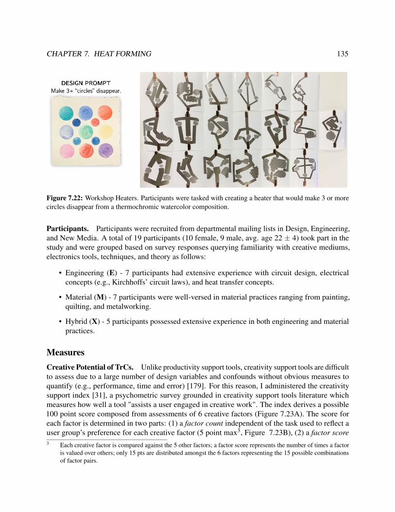
CHAPTER 7. HEAT FORMING 135
Figure 7.22: Workshop Heaters. Participants were tasked with creating a heater that would make 3 or morecircles disappear from a thermochromic watercolor composition.
Participants. Participants were recruited from departmental mailing lists in Design, Engineering,and New Media. A total of 19 participants (10 female, 9 male, avg. age 22 ± 4) took part in thestudy and were grouped based on survey responses querying familiarity with creative mediums,electronics tools, techniques, and theory as follows:
• Engineering (E) - 7 participants had extensive experience with circuit design, electricalconcepts (e.g., Kirchhoffs’ circuit laws), and heat transfer concepts.
• Material (M) - 7 participants were well-versed in material practices ranging from painting,quilting, and metalworking.
• Hybrid (X) - 5 participants possessed extensive experience in both engineering and materialpractices.
MeasuresCreative Potential of TrCs. Unlike productivity support tools, creativity support tools are difficultto assess due to a large number of design variables and confounds without obvious measures toquantify (e.g., performance, time and error) [179]. For this reason, I administered the creativitysupport index [31], a psychometric survey grounded in creativity support tools literature whichmeasures how well a tool "assists a user engaged in creative work". The index derives a possible100 point score composed from assessments of 6 creative factors (Figure 7.23A). The score foreach factor is determined in two parts: (1) a factor count independent of the task used to reflect auser group’s preference for each creative factor (5 point max3, Figure 7.23B), (2) a factor score3 Each creative factor is compared against the 5 other factors; a factor score represents the number of times a factor
is valued over others; only 15 pts are distributed amongst the 6 factors representing the 15 possible combinationsof factor pairs.
CHAPTER 7. HEAT FORMING 136
from two 10-point Likert scale questions (20 point max, Figure 7.23C). The factor count is used toweight the factor score; the resulting values are combined for a holistic CSI score. The index wasused to evaluate the creative act of designing resistive heaters for use in thermoreactive composites;although the workshop task was scoped to thermoreactive watercolors, participants were askedto consider the tool’s support for using the same workflow for other thermoreactive compositecombinations.
Perceiveability of TrCs. Participants filled a post-study questionnaire with Likert scale questionsquerying the perceivability and comfort of working with circuit concepts like resistance, current,power, and Kirchhoff’s circuit laws as well as thermal concepts like conduction. In addition, Itranscribed think-aloud audio, logged design tool interactions, and kept an inventory of heaterprototypes.
7.9 Qualitative ResultsAll participants successfully designed a resistive heater with at least three resistors with differentpower requirements; all but one heater was functional; the defective heater was diagnosed during thestudy by the participant and researcher and resolved to be a printing error. Despite using the samethermoreactive composition, designs ranged from 3-6 resistors with motifs of form-giving heatingelements (e.g., figurative rivers), symbolic relationships with the artwork (e.g., making cool-coloredcircles fade away), or pushing the limits of the fabrication and materials (e.g. maximum temporaldifference; consuming all available power). I first report Likert ratings, CSI results, and then presentthemes that were observed from the think-aloud and semi-structured interviews.
Perceivability Ratings. On average, participants reported on a Likert scale from 0 to 10: comfortwith the design and fabrication process (8.6± 1.1), comfort with working with joule heaters(8.4±1.3), and an understanding of the electricity and thermal mechanics (9.0±1.1). The processand electronics were viewed as approachable (9.1±1.2).
CSI Results. Participant groups notably differed by the value placed on Exploration by hybridpractitioners (count 4.8X versus 3.9E and 3.7M) versus the value placed on Enjoyment by mate-rial practitioners (count 3.1M, versus 2.1E and 2.8X), and Results Worth Effort by engineeringpractitioners (count 3.7E versus 2.7M, 3.0X).
The CSI final adjusted score (Figure 7.23D) for each group breaks down as follows: engineeringpractitioners (65.5± 9.5), creative material practitioners (78.2± 7.4) and hybrid practitioners(84.3±6.4). As a baseline, Cherry et al. reported Google Docs for a collaborative creative writingtask with a CSI score of 87.73 (SD=11.30). These scores suggest a stronger affinity for the toolby hybrid and material practitioners and that an epistemological difference exists that can besupported by creativity support tools. Out of important factors, expressiveness was least supportedfor engineering practitioner (12.1/20.0), many citing a desire to have more control over parameters.

CHAPTER 7. HEAT FORMING 137
Figure 7.23: CSI Index Results
Familiarity of materials and processThe CSI factor score revealed the presence of an epistemological difference between engineering andmaterial practices. Between the two practices, participants distinguished the focus on specification-based problem-solving in electronics as opposed to the open-ended nature of creative tasks. Acommon friction was adapting designs to fit the ecology of materials and components available andhow widely they differ within their class (e.g., choosing motors, microcontrollers). Despite the toolautomatically resolving current, voltage, and resistance values to fit a power specification, the tooldid not provide an avenue for engaging with circuit equations, symbol manipulation or analysis.For engineering practitioners, the inability to engage with circuits in mismatched their creativeprocess. This might additionally explain why engineering participants rated a lower expressivenessscore since such familiar elements drive their workflows for circuit design. The parallel circuitconstruction strategy was viewed as a major comfort and simplification:
Participant X2: I feel so much more comfortable knowing [parallel construction] as adesign parameter.
However, the design workflow removed the need to design for voltage drops introduced fromseries connections and changed the familiar element of symbol manipulation with voltage, current,and resistance characteristic of engineering practice.
Participant X5: I think with voltage and voltage drops. The interface changed this tothinking in terms of power rates and rise times.
In contrast, for material practitioners, the familiarity of material form factors such as paper andink reinforced and matched their creative process. Electronics were viewed as being more brittle,susceptible to dysfunction, and lacking the kind of freedom of combination (or composability) ascreative materials.

CHAPTER 7. HEAT FORMING 138
Participant X3: These are very familiar kind of tools: you use paints, things that looklike pieces of paper, you use colors and those visual signals ... it’s a lot more approach-able than electronics in the other sense; those electronics are daunting, especially whenyou don’t know anything about them.
Hybrid practitioners described their process as sketching with hardware, finding elements thatspur their curiosity, then designing and engineering its function. Many relished the problem-solvingcomponent common in both practices, and described methods of probing and examining the invisiblequality of electronics:
Participant X5: It’s not easy to see what is happening. I work backward, first lookingat readouts from pins. I connect wires to probe and see if I can get the value I expectand keep forming hypotheses until I’m sure I understand what is happening.
The familiarity of both practices by hybrid practitioners acted similar to a buffer solution,resisting and stabilizing adverse effects of defamiliarization, suggesting opportunities to developcurriculum that incorporates multiple disciplinary methods as a means of creating more resilientcreative practices that can withstand exposure to unfamiliar elements.
Aesthetics of Electronics Design ToolsAesthetics played a large role in perceptions of approachability, audience, and use. Participants foundan affinity to the constructionist elements integrated into the tool: the familiarity of icons like thepower symbol, animations like the draining power supply, the focus on color, the friendly rounded-edges of the serpentine patterns, and a nostalgic association and kinship with the Microsoft Paintprogram. Although all participants perceived a clear benefit over current circuit design tools, manystrongly associated the interface as geared towards children. This suggests an opportunity exists toconsolidate how constructionist elements are presented to reflect the aesthetics of professionalism(e.g., encoding variables as visual patterns versus color).
Contract of the Digital HandA common friction and surprise occurred when participants engaged in sketching interactions. Oneinteraction, sketching a path to specify a heat region, caused pause, reflection, and unhappinesswhen the path retained its imperfect, hand-drawn look. In contrast, the digital stitching interactionrendered a smooth, regular, and even space-filling curve as the participant moved their finger backand forth. Participants expected that their hand-drawn strokes would be transformed into “perfect,”aligned geometries. Such computer-mediated elements were seen to form a contract with the user,where both computer and user shared responsibility for the outcome:
Participant E1: If that were automated and [a badly drawn path] happened, it wouldbe annoying. It would think the system should have known better. I would have blamed
CHAPTER 7. HEAT FORMING 139
it on the system, but having drawn it I feel like I take some responsibility in whatactually happened.
This suggests that opportunities exist to design onboarding practices that scaffold and balanceresponsibility between human and machine to slowly instill reward and confidence.
Role of the Digitial Stitching InteractionIn order to generate the serpentine pattern, users had to carry out a digital stitching action with aphysical gesture; the serpentine path would only be generated once the amount of effort matched theresistance (and power rate) of the region in order to communicate how resistance reduced the heatgeneration rate of respective heaters. This stitching interaction was met with a bimodal response.Foreseeing the need to design a joule heater quickly, engineering and hybrid participants viewed theinteraction as fun but frustrating and desired the ability to access this interaction as a configurablesetting, scoring its value as a 2.9(1.9)[E] and 3.2(0.8)[X] on a 5-pt Likert. However, when theserpentine algorithm produced an undesirable result, participants viewed it as a troubleshootingtechnique that communicated the limitations and process of the serpentine algorithm.
Participant E4: It feels like a troubleshooting technique; doing that motion makessure that [the circuit] is okay. For me, it’s another level of check that makes you aware.
Material practitioners scored and perceived the digital stitching interaction quite differently4.9(0.4)[M]. Initially viewing the act of making the serpentine pattern as complicated, they foundthe act of creating the serpentine pattern as engaging, joyful, and instilling agency:
Participant X5: It was fun and felt like you were making it; like you had a role in thework.
Participant X3: It made me feel like I was building the circuit myself; it gave me anunderstanding. I could have done it the other way [automatic generation], but creatingthe [traces] myself made me know what’s going on inside.
Power as a creative materialBefore being introduced to the tool, participants revealed different mental models of heat: oneparticipant likened heat as a flow, taking time to move through materials; others described heatin terms of the everyday control mechanisms, e.g., controlling strength with a stove dial. As acreative material, many considered heat a byproduct: When I work with heat, it’s about minimizingheat. Heat is not a desirable property (Participant E4). Electronics behind heat were perceived ascomplex; however, one participant, having previously deconstructed a hot glue gun, noted:
Participant X3: I thought [the glue gun] would be very complicated, or anything thatworks with heat. I took it apart and found that the only thing that was producing the

CHAPTER 7. HEAT FORMING 140
heat was these two metal plates ... It’s actually just a resistor in there! It was rathersurprising that it was so simple.
When participants were presented with the water-flow modeling analogy, reactions were mixed:some had never heard the water-flow analogy, yet were surprised at how easy it was to pick up or howmuch it aligned with their mental model. For engineering participants, the water analogy misalignedwith their way of thinking, having already constructed a model based on formal definitions. Theextension of the thermoelectric concepts, i.e., electron water colliding with resistive rocks caught bythermoreactive nets, was welcomed by all and viewed as a natural extension and “filling a gap.”
The thread metaphor was viewed positively by all participants. Many described annotations ofcurrent and resistance in the cognitive background; their main focus was working with watts anddistributing power to heat spaces. A major conceptual discovery that occurred with all participantswas understanding power as a finite quantity.
Participant X4: I quickly realized from how the power source was draining that thereare only so many watts available.
Compared to probing circuits with a multimeter, evaluating the heater with the liquid crystalsheet was preferred by all groups. As a visually engaging medium, the liquid crystal encouragedusers to think about the mechanics of heat.
Participant E4: It is so cool to watch the liquid crystal change color. It makes methink about how the heat flows through the paper and heat transfer in general.
Participants noted a shift in how they conceptualized electricity and their relationship towards it.
Participant X4: It changes your relationship to electricity completely. I think it showsyou a different aspect of electricity; where electricity doesn’t just hurt you, shock you,is just used to power your electronic device, but can be used creatively... this processmakes it more intimate.
The perceivability of electric heat and the material ecology around TrCs drove participant’sperceptions about electricity:
Participant X5: The [TLC sheet] fixes electronics for me. It is a different, more fun,way of seeing electricity happen.
Participant M4: I feel electricity as more friendly, and I would enjoy doing this athome.
Participant X3: I thought that electronics were their own system. They are dauntingsince you don’t know anything about them. They are closed-off. I can’t go into thatand touch things and find out how to work with them. Now, I can put [thermoreactivematerials] on [heaters], and they will respond. I can do different tests with it. It feels a
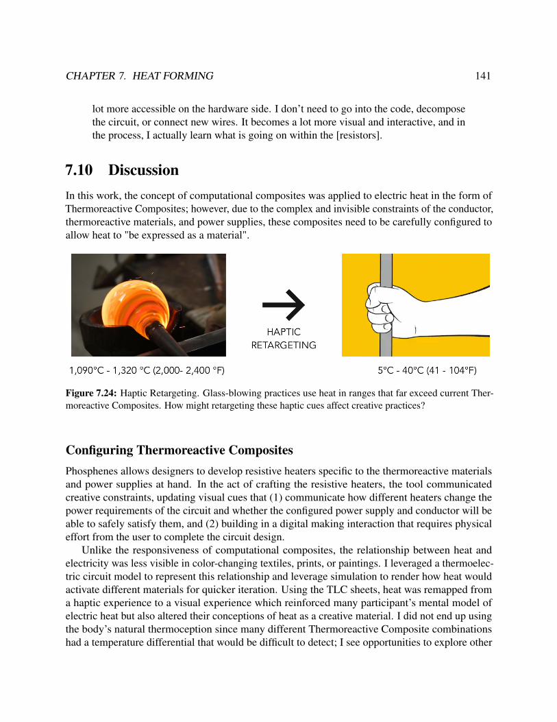
CHAPTER 7. HEAT FORMING 141
lot more accessible on the hardware side. I don’t need to go into the code, decomposethe circuit, or connect new wires. It becomes a lot more visual and interactive, and inthe process, I actually learn what is going on within the [resistors].
7.10 DiscussionIn this work, the concept of computational composites was applied to electric heat in the form ofThermoreactive Composites; however, due to the complex and invisible constraints of the conductor,thermoreactive materials, and power supplies, these composites need to be carefully configured toallow heat to "be expressed as a material".
Figure 7.24: Haptic Retargeting. Glass-blowing practices use heat in ranges that far exceed current Ther-moreactive Composites. How might retargeting these haptic cues affect creative practices?
Configuring Thermoreactive CompositesPhosphenes allows designers to develop resistive heaters specific to the thermoreactive materialsand power supplies at hand. In the act of crafting the resistive heaters, the tool communicatedcreative constraints, updating visual cues that (1) communicate how different heaters change thepower requirements of the circuit and whether the configured power supply and conductor will beable to safely satisfy them, and (2) building in a digital making interaction that requires physicaleffort from the user to complete the circuit design.
Unlike the responsiveness of computational composites, the relationship between heat andelectricity was less visible in color-changing textiles, prints, or paintings. I leveraged a thermoelec-tric circuit model to represent this relationship and leverage simulation to render how heat wouldactivate different materials for quicker iteration. Using the TLC sheets, heat was remapped froma haptic experience to a visual experience which reinforced many participant’s mental model ofelectric heat but also altered their conceptions of heat as a creative material. I did not end up usingthe body’s natural thermoception since many different Thermoreactive Composite combinationshad a temperature differential that would be difficult to detect; I see opportunities to explore other

CHAPTER 7. HEAT FORMING 142
modalities like activating scent as a way to engage more of the body in sensemaking or developa haptic device that senses these minute changes in temperature and renders them to match thepsychophysics of the body.
Participants found that many of the tool’s elements receded into the cognitive background asthey actively engaged in wayfaring behaviors, corresponding with the morphogenetic (or form-generating) making [85]. Specifically, I observed designs evolve as participants interacted with thetool, especially influenced by the diminishing “power spool” that would respond to changes in thedesign or from the quality of heat distribution when using the TLC sheets.
Figure 7.25: Copper Heat Smoothing. (left) A two-branch joule heater activates a TLC sheet; (right) athin-sheet of copper is placed over the original heater, smoothing out the serpentine heat pattern.
Alternative Sites for Crafting HeatAlthough the relationship with electric heat was conveyed and approachable, the creative potentialfor heat was only slightly breached. Phosphenes lowered the barrier and expense of visualizingheat interactions using TLC sheets and the design time for fabricating a custom heater. Figure 7.21shows one Thermoreactive Composite (silver ink, thermochromic PLA) that reached the creativebounds of the resistive heaters. With a 2-3W power limit, silver ink could only trigger changesin particularly thin walls of thermochromic PLA in the < 1-minute range. However, changing thethickness of the walls was another way in which heat could be controlled and mediated since moremass requires more energy to activate. In this way, the thermoreactive material becomes the site inwhich heat is crafted. Mass is just one of many design variables that heat sink design is well suitedto capture. While heat sinks are traditionally made from metal, it would be useful to also captureand incorporate these design practices into Thermoreactive Composites.
Extending Heat as a MaterialAlthough systems with Peltier elements have introduced cooling elements [144], controlling howthermoreactives react when cooling remains an unexplored creative area. A wider range of thermalmaterials could enable new creative dimensions. Thermal insulators like silicone could be used to

CHAPTER 7. HEAT FORMING 143
Figure 7.26: Could shaping three-dimensional wire forms created three-dimension heat forms?
edit, erase, and refine joule heater elements. Other conductive materials may include mechanically-attached heat sinks for selective heat transfer or the use of thermal compounds (pastes and adhesives)to smooth out heating artifacts. Cross-flow blowers could introduce a convection element and pushcool or warm air through air-pipes in 3D objects([170]) to influence thermoreactive materialactivation. Silver ink is limited in both its power rating and archivability. While copper-platedPCBs serve as an alternative, other physical, creative practices like wire bending can be introducedto create stable three-dimensional heating elements and support broader working ranges. Ourtechniques worked well for material activations under the human thermal perception threshold, butworking with hotter materials tangibly remains an open question that creative practices like glassblowing and welding may inform.
Immaterial CompositesWith immaterial composites, I found that by coupling an immaterial with a physical proxy, behaviors,structures, and forms can become readily visible and manipulable. I demonstrated this techniquefor electric light (Chapter 6) and electric heat (Chapter 7).
Building on the concept of the computational composite, the binding of the immaterial to thephysical proxy had much more nuance; if properly calibrated the two coupled materials could be insynergy – this is the site that I see computational design having a distinct advantage over analogmethods.
The wide breadth of materials and their internal properties is something that could be capturedby sensors. For example, for wood carving using a combination of infrared, light, a piezo electronicscould characterize the softness of the wood and provide this type of feedback to the user. Heat,because of its slowness, also proved to showcase more of the nuances of properly calibrating theinput and output thresholds of the composite.

CHAPTER 7. HEAT FORMING 144
7.11 SummaryI demonstrated a Crafting Proxy for designing resistive heaters within Thermoreactive Composites.Through the computational design of heater geometries and a thermoelectric model, our systemexposed the ability to craft resistive heaters that distribute heat spatially and temporally as specifiedwhile accurately activating a range of thermoreactive materials. In a formal user study, I validatedthat our design and fabrication workflow facilitates an iterative design cycle that conveys both elec-trical design and thermal design concepts and renews the role of heat as a creative material. Throughthe Creativity Support Index, the study revealed a greater affinity for a material epistemology andthe potential for composability and perceivability to act as driving design variables to support abroader range of users to participate in digital fabrication.
I found that, like in Chapter 6, computational design could similarly be used to interface heatand thermoreactive materials. However, because of the limited perceivability of heat, I needed tointroduce a design step to remap physical stimuli to be perceivable and understandable and increasethe information bandwidth of the physical stimuli.
In the next chapter, I discuss how the compositing design pattern can be extended to work withmagnetism, UV and infrared light, biomaterials, and even new computational materials like neuralnetworks. The next central challenge is understanding how more stimuli can be mapped to thehuman perceptual system in this way, engaging more of the body in the sensemaking process.

145
Chapter 8
Discussion
This work leveraged a Research through Design (RtD) methodology to build intermediate-levelknowledge around the design, implementation, and evaluation of Crafting Proxies. The conceptof a Crafting Proxy serves to formalize the different capacities that an intermediary between amaterial and a practitioner can serve within a material practice. I explored three different areasof the Crafting Proxy design space – armatures, mediators, and lenses – each situated in materialpractices with wire, light, and heat, respectively.
In this chapter, I reflect on how the compositing design strategy can be generalized and appliedto new material and immaterial contexts, design principles to navigate the design space, and theextent to which material practices can be studied and supported using our proposed method.
Figure 8.1: Crafting Proxy Design Method
8.1 Crafting Proxy Design MethodThe Crafting Proxy Design Method is a material-centric approach aimed at designing a tool for amaterial situated within a practice. For instance, applying this method to a material like wood in awoodcarving practice aims to foreground the “talk-back” of wood to develop a deeper relationship

CHAPTER 8. DISCUSSION 146
between the practitioner and material. This is in contrast to Computer-Aided Design (CAD) toolsthat work with an abstracted material (e.g., voxel or mesh) aimed at codifying existing woodworkingtechniques to be usable within a CAD-CAM pipeline.
The act of designing Crafting Proxies for both materials and immaterials allowed us to assessthe boundaries of the Crafting Proxy design space and surface key considerations not addressed bythe current compositing strategy, including:
• How do we interpret an immaterial’s “talk-back” within a creative practice?
• How does an immaterial’s “talk back” inform creative action and forms?
• How do we configure immaterials within a composite?
• How do we facilitate a material encounter?
I describe how our three-phase method addresses many of these challenges, motivate our designdecisions, and address the limitations of our approach.
Extracting a Material’s Conversational ProfileThe aim of extracting a conversational profile, much like a persona, is to inform the design processto be centered around a material, intended to satisfy and amplify the “talk-back” in a reflectivepractice. In Chapter 2, I formalized three components of a conversational profile (Table 2.1) toincorporate into Crafting Proxies: sensorial feedback, affordances, and tradition.
To understand a material’s sensorial feedback, I leveraged two analytical techniques. Usingformal analysis [133, 11], I formulated a description of the arrangement and function of form-givingelements in a collection of artifacts. This technique aims to explain how the phenomena that weexperience alters and informs our experience of a larger composition. While formal analysis isonly intended to describe phenomena, it has the tradeoff of introducing a medium specificity bias- focusing on purely the physical properties of the materials versus identifying the sociomaterialqualities (e.g., the experience of a knitted blanket from loved one, versus a machine-made blanket).
To counteract this bias, our analysis leveraged Giaccardi & Karana’s material experience frame-work: For instance, in analyzing the Virgen the Guadalupe lamp, I explored how the performativeelements (the object situated as a religious artifact), was supported by the affective elements (lightas ethereal), defamiliarized at the interpretative level (optic fiber evoking a techno-aesthetic), anddecomposed at the sensorial level (light fading, strobing, glimmering, reflecting, and refracting).These sensorial components were then clustered and synthesized into the conversational profile.
To understand affordances and tradition, I leveraged ethnographic apprenticeship techniques [215,162]. For instance, in entering the practice of wire wrapping, I began as a novice and gained ex-pertise, documenting important learning moments, experiencing error, and reflecting on the tacitknowledge developed in the act of engaging with wire. This allowed me to experience the af-fordances that guided my wire forming process. In situating myself in the larger community ofpractitioners, I positioned the wire forms in the tradition of wire wrapping practice as opposed to

CHAPTER 8. DISCUSSION 147
engaging with forms enabled by new technology. This allowed me to develop a sensitivity for style,or the “constancy, or consistency, in the way an individual, or a group, treats the formal elementsof art, or visual culture” [69]. However, as is common in ethnographic approaches, I introducebias from my own predilections and the Western-oriented community of practice I became a partof. I see value in posing conversational profiles as a research area to develop across the variety ofmaterials and practices that exist across cultures and disciplines.
As a reference, the profiles I synthesized are found in Sections 5.6, 6.3, and 7.3.
Expanding ComposabilityI used the resulting conversational profile to define a target material manipulation space. The goalof this design phase is to identify the current means of manipulating a material, i.e., its materialAPI, and develop techniques for spanning a larger manipulation space to improve the composability,or malleability, of a material.
For light, the material manipulation space was bounded by the LED, limiting composabilityto light intensity and color. From optoelectronics literature, I identified methods of decomposinglight into three components: a control module, beam-shaping module, and diffusing module. I thendeveloped computational design algorithms that used an SVG as input to expand the repertoireof available forms, including hard-soft edge definition, textured diffusers, non-traditional controllayouts, and passive haptic and deformable light interactions.
For heat, I explored a manufacturing technique for creating silver-ink inkjet-printed resistors.Used primarily as a binary heat-generating element, I developed computational design routinesthat expanded the expressivity of resistive heaters as a spatiotemporal medium. By modulatingtrace resistance by trace width and laying traces with space-filling curves, resistive heaters weredesigned to generated heat over target, non-rectilinear regions of interest. Through a circuit dividerconstruction pattern, multiple heaters were arranged in parallel and configured with different heatgeneration rates, allowing resistive heaters to activate thermoreactive material over time.
Our composability strategies benefited from established engineering principles and advances inmaterial fabrication techniques but shared a common computational design base. Computationaldesign in these situations was used to surface material interactions (e.g., light and its interactionswith refractive and reflective materials) and actively support creating and refining mental models(e.g., using dynamic modeling analogies). However, leveraging computational design is prone tointroduce a maker-bias, where although a wider, more open-ended API is supported, it still reflectsthe design decisions and philosophies of the developer. I built our computational design engineon the SVG so as to incorporate the repertoire of 2D design skills that have developed acrossdisciplines; as I discuss in this chapter, this allowed for unintended uses of the design tool which Isee as a promising method to mitigate maker-bias.
Tuning PerceivabilityMany immaterials have limited external states that are readily perceivable by the human perceptualsystem or understood by human cognitive processes. I incorporate a perceivability step focused on

CHAPTER 8. DISCUSSION 148
configuring a composite to communicate its forms, structures, and behaviors of an immaterial. Iapproached this dimension from two approaches:
• From a perceptual approach, I examine how the physical stimuli produced by the physicalproxy can be reconfigured to increase the information bandwidth to precognitive processes.For instance, the heat produced by the resistive heaters was remapped as a visual stimulususing thermoreactive materials. Using a formulation of liquid crystal that activates in therange of temperatures used in our target applications 91−101F (32−37C), heat stimuliwas remapped to red, green, and blue color changes that allowed visibility of the temporalcomponent of heat transfer.
• From a cognitive approach, I examined how heat and electric interactions are communicatedin formal education. I developed a unified heat-electricity modeling analogy through a threadmetaphor, which was then integrated into the design workflow as a dynamic modeling analogy.In the act of designing a heater, dynamically generated perceptual cues communicatedelectrical and heat behaviors. For instance, power as a finite material was communicatedusing a diminishing power spool that would lose “thread material” when heaters in the designdrew more power.
This process made clear the bias towards visual, touch, and audio interfaces and the extent towhich computational control can be enacted on physical stimuli. I discuss in future work trajectoriesfor increasing the perceivability of immaterials and incorporating more of the human perceptual,cognitive, and motor abilities to engage in sensemaking.
8.2 Design Principles and Strategies for Crafting ProxiesIn the following section, I describe design considerations, concerns, and strategies that arose fromdesigning Crafting Proxies. These insights are synthesized across the proxies created, artifactsformed, and workshop evaluations in this dissertation.
Designing for SensemakingIn this work, I explored two immaterials, light and heat, and formed composites with physicalmaterials. These physical materials acted as mediators, remapping immaterial behaviors, forms, andstructures to perceivable stimuli. From our design workshops, I observed the following principle:

CHAPTER 8. DISCUSSION 149
Sensemaking Principle. Proxies that mediate the representation of a material(e.g., via simulation) benefit from cool, low-definition representations. Theserepresentations elicit active participation from the practitioner to make sense ofwhat is occurring. Designing proxies to be open-ended, i.e., for unintended uses,can improve how proxies are reappropriated and controlled by the practitioner tomake sense of their larger creative environment.
Hot and Cool Proxies. For light, I used a light simulation mediation strategy consisting of a raytracer that would project rays from an SVG element annotated as an LED. These rays reacted tothe geometries of other SVG elements annotated with refractive or reflective material properties.The simulation navigated the startup costs of housing, controlling, and programming LEDs, andallowed users to construct material knowledge through direct manipulation interactions. However,as intrinsic to all simulations, the simulacrum of real-world interaction was incomplete. To enablefaster render times, a fixed number of rays were cast with a fixed number of bounces and renderedon a 2D-abstracted representation of the scene (Figure 8.2).
Figure 8.2: A simple light simulation of LEDs in a California Bear reflector geometry. (left) A CoolSimulation - Low-definition media that engages the senses less completely; (right) A Hot Simulation -High-definition media.
In the partial representation of the real-world, the light simulation forced users to “fill in thegap.” This is a quality of media that Mcluhan [126] describes as cool – a low-definition mediathat engages senses less completely and requires greater amounts of interaction from the audienceto construct a full representation (e.g., phone conversations, comic books). The low definitionsimulation allowed users to visually track individual rays and observe their individual behaviorswhile at the same time observing the gestalt of the simulation and the larger meta-behaviors of theLED (Figure 8.2). In a hot version of the simulation, this quality would be relegated to a purelyvisual processing task.
The simulation also introduced a maker-bias, similar to blackboxes, where the end-user prac-titioner does not have control over what was defined as the API. In our simulation, deciding toreduce the fidelity of the ray tracer had the tradeoff of reducing the saliency of shadows. Lacking aglobal illumination component, the material profile light as shadow creator was less supported inthe luminaire design tool.
For heat, I used a passive mediation strategy leveraging Thermochromic Liquid Crystal (TLC)sheet to transform heat into a visual stimulus, remapping temperature ranges from 91− 104F

CHAPTER 8. DISCUSSION 150
(32−40C) to a red-green-blue spectrum. This rich visual feedback allowed practitioners in theworkshop to experience electricity as “friendlier,” changing the affective qualities of electricity asa material. As a passive configuration, the liquid crystal sheet bypassed the maker-bias, readilyintegrating into material practice and facilitating experiments and explorations with materials notoriginally scoped for the proxy. As an example of a hot proxy, liquid crystal provided a high-fidelityrepresentation, but in contrast to other hot media like photographs, the production and elicitationof this information are controlled by the practitioner. Because the thermoreactive materials usedin Phosphenes all activated in the TLC activation range, the thermoreactive composites wereeasily configured with this passive material. However, material practices like glass blowing have aworking temperature range of 1,090−1,320C (2,000−2,400F); this type of proxy would proveineffective. In this situation, a digitally-mediated material that haptically retargets these stimulidynamically would prove a more versatile proxy.
Developing the Aesthetics of Techno-MaterialsIn this work, I described three different ways that materials propose alternative courses of actionduring the creative process. While affordances are intrinsic material qualities, I demonstrated thatproxies could be designed to mediate sensorial feedback via computational simulation (ray tracingfor light) or through perceptual remapping (visualizing heat transfer through a thermoreactive liquidcrystal).
However, focusing on these physical qualities reduces the sociomaterial dimension of artifactsto a perception task as opposed to a situated material engagement [162]. Capturing the tradition-communicating elements of materials are central to subverting the influence of sameness andmass-reproduction ideology of manufacturing practices. From design artifacts I created, I observedthe following principle:
Aesthetic Development Principle. As new materials and fabrication techniquesdevelop, Crafting Proxies benefit from tracing and connecting the semiotics ofmaterials, or the longer history and origins that assign meaning to a material.
Part of my design process focused on analyzing and producing artifacts with religious motifs(Figure 8.3). Religious artifacts are unique in that their forms are heavily influenced by a material’stradition-communicating elements, versus their sensorial feedback or affordances. These artifactsleverage a material’s intrinsic and symbolic worth to actively create a unique meaning or experience.For instance, the scarcity of a material like gold and its cultural value is used to communicate theauthenticity and “oneness” of an artifact. Benjamin describes this quality of uniqueness as the auraof a work which is displaced when artifacts of mechanical reproduction are introduced [15].
In the Virgen de Guadalupe lamp, a religious artifact described in Section 6.3, I described how amechanical light sequencer was able to create an experience that a programmatic light sequencerdisallowed. The use of optic fiber to transport light and create light textures further moved away

CHAPTER 8. DISCUSSION 151
Figure 8.3: Semiotics of Traditional Materials. (left) Virgén de Guadalupe Fiber Optic Lamp, (center)Phosphenes Buddha Mala, (right) Illumination Aesthetics Illuminated Hairbrooch
from the commonplace point-light aesthetic promoted by the ubiquity of the LED. In the BuddhaMala, I created a devotional interface for engaging in ritual action. The non-emissive nature ofthe display altered the experience of computer-mediated visuals, adding an element of personalidentity and objecthood. The interface served as an example of a slow technology, evoking a longer,sustained, and ritual interaction. In anchoring materials with its symbolic and cultural signifiers,I see future potential for proxies to develop the aesthetics associated with techno-materials, ormaterials associated with technology. For example, the 8-bit audio [33] (e.g., chiptunes in videogames) formed as a result of the limits of memory and expressivity of audio synthesizers in the1980s. As techno-materials develop, how can these aesthetics be traced to a longer history of makingthat is not solely embedded within post-modern practices? For instance, with the illuminated hairbrooch, although the glass-silicone diffuser achieved physically novel effects, the tradition of usingglass and light together has a long, intricate history in the practice of stained glass, cathedrals,and religion. Within ethnocomputing, how might we foreground the tradition-communicatingproperties of materials used within indigenous and other underrepresented communities in emergingtechnologies like digital fabrication and e-textiles?
Sustaining PracticeA large focus of creativity support tools is on idea generation, but a clear differentiating quality ofCrafting Proxies is the need to develop an intimate relationship with the material. In Chapter 5, Idescribed how a mass-manufacturing aesthetic removes the human hand from fabrication, limitingthe potential for material encounters to occur to at most a post-processing step. A central aim ofthe proxy is to re-introduce or augment material encounters; however, this is only effective if apractitioner sustains themselves in practice. From our workshop evaluations with practitioners ofvarying expertise, we observed:

CHAPTER 8. DISCUSSION 152
Sustainability Principle. Agency and the risk are interconnected social motivators behindcreative activity. Perceptions of agency can change the expected reward from engaging orcompleting a creative task, while risk can change the motivation for deviating and exploringnovel forms. To achieve a deeper engagement with a material, different configurations ofthese two motivators are needed for practitioners to sustain interactions with a material andpractice versus motivating a desire to build craftsmanship.
Risk-Prone Material Encounters. A central challenge of Crafting Proxies is achieving thedelicate balance between risk and agency. Risk can emerge in a series of different contexts increative practices, from the risk of damaging or wasting a scarce material or an unsuccessfulartifact or experience (workmanship of risk), or the psychological risk from being perceived asless capable [194]. With the armatures developed in Chapter 5, I saw how the riskiest proxy, theschematic, forced workshop participants to carefully plan, sanity check, and form their wire tomatch the prescribed design. As might be expected, the perceived risk prevented novice and expertpractitioners from deviating or innovating with their design. However, as a tradeoff, this risk alsoencouraged workmanship, especially by expert practitioners who demonstrated their ability toaccurately replicate a prescribed form. For novices, this risk limited their ability to develop self-efficacy in the creative practice, but, because of the caution needed, caused a heightened awarenessof the material and its interactions — in this sense yielding the strongest material encounter. Tosustain practice, introducing risk is a later stage design dimension to activate, especially as a meansof encouraging deviation and exploration. However, too little risk and a practitioner’s motivation toactively construct and refine material mental models is affected.
Ritual. In contrast, the jig proxies reduced the cognitive load and physical dexterity needed toaccomplish the wire wrapping task, allowing users to engage in ritual action. While the awareness ofthe wire or agency to deviate was most restricted in this situation, it also was the practice that elicitedthe most enjoyment and potential to continue engaging in the practice. This material encounter isdeveloped over time, but more importantly, sustains activity and builds familiarity with a material.For creativity support tools, this suggests that the repetitive, redundant, and tedious actions havean important role in sustaining practice and can be best utilized when they can be transformed asenjoyable and ritual.
Embodied Interactions. Embodied interaction, the enactment of knowledge and concepts throughthe activity of our bodies [114], is a distinguishing quality of a material epistemology. Throughphysical interaction with a material and the creative environment, the body of the material practi-tioner is actively involved in sensemaking. While the Crafting Proxies developed each allowed for amaterial encounter, interactions with tablets, computers, mice, and pens limited the extent to thebodily actions that could be included with computational technology. In Phosphenes, I introducedan embodied stitching interaction that required users to carry out several physical swiping motionsto lay out a serpentine trace. This interaction, while intended to convey the relationship between heat

CHAPTER 8. DISCUSSION 153
and resistance, had the effect of causing participants to feel agency in their actions (X5: “. . . felt likeyou were making it; like you had a role in the work”) and reflection (X3: “It made me feel like I wasbuilding the circuit myself . . . creating the [traces] myself made me know what’s going on inside.”).This stitching interaction did not introduce any additional risk — serpentine patterns were alreadyprecomputed, and the users stitching actions were not linked to its design. For material practitioners,the serpentine pattern was perceived as intimidating, but the stitching interaction allowed themto develop familiarity with the serpentine pattern and reassess their relationship with electricity(M4: “I feel electricity as more friendly, and I would enjoy doing this at home.”). While risk wasmuch less pronounced than its counterparts, the Phosphenes CAD tool mitigated the aesthetic ofCAD tools instantly producing results, and instead invited the practitioner to actively participate insensemaking.
Supporting Idea Generation through BricolageIn the series of three workshop studies described in this work, I reflect on when designs created byparticipants led to creative insights and innovations outside of what was “designed into” the tools,leading to the following observation:
Cognitive Bias Principle. Crafting Proxies benefit from introducing an acute cognitive biasas a creative constraint, framing the practitioner’s actions towards a particular way of thinking.Such proxies need to support tool-switching, not constraining the practitioner to only thinkingin a single style. When a part of a larger environment of tools and materials, such proxies cansupport a bricolage practice.
In Illumination Aesthetics, I saw a participant with a deep practice using Adobe Illustrator ina graphic design practice able to fluidly transform her design intention into a series of booleanshape operations. When coupled with the ray-tracing light simulation, this participant developed adialectical relationship between geometry and light that went beyond light “filling up a shape” likethat of a pixel. Instead, the light forms she created cast light as a gradient-maker. In this regard, thesuccess of this interaction was enabled by the ease of mapping this unknown (electric light) to aknown material in the practitioner’s repertoire (linear and radial gradients). These light gradientswere then appropriated to create subforms of shadow and highlight common in graphic designpractices. In this process, I saw the strength of cognitive bias arising from a deep practice with thetool (within a graphic design practice) in being able to reappropriate this unknown material. Theresulting forms were significantly different from other participants’, who although had previousexperience with vector editors had not used the tool within a graphic design practice.
In ProxyPrint, I saw another instance in which an expert wire wrapper used support geometriesnever intended for the final design as additional sites to wrap a wire. For her, this proxy jigtransformed everything into a wrappable site, much like the canonical example of cognitive biaswith the hammer making everything look like a nail. The interaction with this jig had a wider effect,casting other objects in the space as sites for wire-wrapping.

CHAPTER 8. DISCUSSION 154
I see this quality of tool’s cognitive bias as central to crafting aligning with the bricolage viewthat the creative process is influenced by the available materials, tools, and skills in the environment.In this regard, increasing the potential for creative insight and innovation can be as simple asintroducing tools that elicit and cognitively bias practitioners towards a different way of thinking,or that defamiliarize the situation at hand. Such tools share the properties of being modular anddisjoint but facilitate tool-switching, or readily accepting and adapting to the “inputs” of formsgenerated during a creative exploration.
8.3 Extensions of the Crafting Proxy Design MethodA core contribution of this work investigated and operationalized compositing as a design methodthat could extend beyond computational composites. Compositing allowed for a Crafting Proxy toact as mediator and lens, directly grafted onto immaterials and configured to increase the informationbandwidth between physical stimuli and the human perceptual system. I explored this technique ontwo immaterials, light and heat, and found that each immaterial presented unique challenges.
Our process introduced a composability phase where the material API, or the available inputsand expressivity of inputs, is used to create more malleable materials. For light, the use of secondaryoptic elements allowed for LED to be decomposed, with each component accessible and configurablethrough computational design. For heat, the use of a parallel resistive heater construction allowedfor heat to be accessed as a spatiotemporal medium.
Our investigations revealed that heat, at the temperature ranges we were dealing with, wasdifficult to perceive. In contrast, heat used in glass blowing practices causes both visual changes inthe glass, changes in glass plasticity, and transfers heat to the environment that is sensed by the fullbody. I further developed the compositing method to include a perceivability phase that introducedconsiderations for mapping the proxy’s physical stimuli to human psychophysics. In our workshopstudy, these perceivability mechanisms were shown to make heat and electronics more approachableand support a material epistemology.
Moving forward, I see this compositing method as serviceable to current and emerging imma-terials, including biomaterials, electromagnetism, neural networks, chance, and beyond. Below, Idescribe how compositing can be approached for a subset of these immaterials.
Biomaterials: Vibrio harveyi. Vibrio harveyi is a bioluminescent marine bacterium. Found intropical waters, this microorganism has been associated with the milky seas effect, a phenomenonwhere ocean waters produce blue light. Future environments might leverage such an organism as asustainable alternative to silicon-based light, such as to provide alternative sources of lighting in theurban environment. Advances in genetic engineering and the isolation of the bioluminescence geneindicate a potential development of other bioluminescent organisms, including fungi and flora.1 Image credits (left to right): priyanka from The Noun Project https://thenounproject.com/term/cell
/1764085; Puneet Varma at Alchetron from https://alchetron.com/Vibrio-harveyi; UniDx from https://unidx.org/; Jim Deacon from http://archive.bio.ed.ac.uk/jdeacon/microbes/shape.htm

CHAPTER 8. DISCUSSION 155
Figure 8.4: Proxies for Biomaterials1
As a microorganism, the ability to manipulate or view the organism requires building a mentalmodel that is difficult to acquire experientially. To understand and expose bioluminescence as adesign material, we can adopt the conversational profile of light as a base. The conversational profilecan be further developed from incorporating the biomateriality introduced by Vibrio harveyi. Asoriginating from a living organism, bioluminescence was the ephemeral and environmentally depen-dent behaviors of reproduction, mortality, and lifespan. As free-moving organisms, biomaterialityalso includes complex motile relationships like clustering.
For composability, liquid control techniques, such as microfluidics, can be used to increasethe malleability of this marine bacterium. For perceivability, working with biomaterials operatesover long temporal scales. In this regard, insights learned from working with heat could be usedto inform methods for increasing temporal perceivability or likewise from material practices likegardening. Furthermore, sensing routines, such as optical flow analysis of video microscopy, couldbe used to track bacteria colonies and support an experiential encounter with bacteria.
Figure 8.5: Proxies for Electromagnetism2
Electromagnetism. Electronic components like electromagnets are commonly used to generate acurrent along a coiling conductor and produces an electric force. This phenomenon is very similar2 Image credits (left to right): emilegraphics from The Noun Project https://thenounproject.com/term/elec
tromagnetic-fields/437916; ToySharing Magnetic Building Set from https://www.amazon.in/s?k=ToySharing; Gambini et al. [55]; cstephenmurray from https://youtu.be/snNG481SYJw.

CHAPTER 8. DISCUSSION 156
to our explorations of electric heat and electric light, but to a larger degree produces a result that isdifficult (if not impossible) to perceive unaided by the human body.
For electromagnetism’s conversational profile, rare earth magnets are readily integrated into avariety of mechanisms in material practices, creating a vocabulary of attraction, repulsion, release,and alignment. The electric materiality (via the analog control mechanisms) are closely tied tocomputational materiality (via the digital signal used to control the components).
Electromagnetism has a well-defined composability; as its base unit, coils are an elementarybuilding block to weave forces. The coil presents a site for computational design to expand thecomposability of magnetic fields. Much like I resolved electrical and thermal interactions with athread-based modeling analogy, a Crafting Proxy for electromagnetism could leverage a similaranalogy to communicate the relationship between the thickness of the coiling wire and the numberof winds and support its manual creation through armature proxies.
Magnetism is difficult to perceive; however, through the ubiquity of rare earth magnets, themental model for magnetic interactions is well established. Communicating magnetic fields iseasily achieved through simulation [12] and could employ similar feedback mechanisms likethe ray tracer used in Illumination Aesthetics. However, more tangible variants (such as ironfilings), could be used to provide physical cues that reinforce mental models. As a programmablematerial, electromagnets can be controlled to produce magnetic fields in static locations but atdifferent strengths and polarities; these properties are not readily perceivable. Coating coals in athermoreactive material like liquid crystal can leverage the heat byproduct as an indirect indicatorof strength. An environment with a grid of magnetometers could also be used to communicate howmagnetic fields are being generated; as a largely haptic conversational profile, such environmentscould help expand the haptic vocabulary of electromagnetic interactions.
Developing proxies to express electromagnetism as a material has much larger implications forthe host of materials that fall under the electromagnetic spectrum, including UV and infrared light.
8.4 SummaryDesigning Crafting Proxies revealed several nuances for supporting a material epistemology. Isynthesized these insights into a three-part design method: resolving the conversational profile ofthe material, expanding its expressivity, composability, and malleability, and tuning physical cuesproduced from interactions with the material to match human psychophysics.
To support creativity, I identified the need to create cool feedback mechanism, or mechanismsthat relay an incomplete picture to actively engage the practitioner in sensemaking. I discussedthe need to anchor materials in their cultural, social, and symbolic values to regain the aura of anartifact and connect aesthetics to established practices. Lastly, I relayed how tools that introducea clear cognitive bias support a bricolage practice, and when part of a larger ecology of tools andmaterials can support idea generation. To sustain practice, I discussed the role risk has in developingcraftsmanship, ritual action in building familiarity with a material, and embodied interactions inaltering perceptions of agency.

CHAPTER 8. DISCUSSION 157
Lastly, I described and reasoned how our proposed method could be applied to other immaterialsincluding biomaterials, like bioluminescent microorganisms, or immaterials like electromagnetismto come into expression as a craft material. I claim that many of the conversational profiles areportable to other materials which suggest a potential to construct a material ontology that can helpidentify how two similar materials can benefit from the set of ways that diverse practices havedeveloped for interpreting or composing them.
In the next chapter, I describe a vision of how material practices and digital fabrication mightdevelop and describe areas of future work for supporting creative thinking, foregrounding existingmaterial knowledge, and engaging a more comprehensive range of motor, perceptual, and cognitiveabilities in augmented creative environments.

158
Chapter 9
Computational Design Architecture
Every proxy design implemented in this dissertation leveraged a common computational designengine that has evolved throughout this research. In this chapter, I describe the architecture thatwas purposefully designed at its onset to relegate 3D design to a 2.5D space in order to leverageexisting skills and mental models familiar to material practitioners. This prototyping techniqueallowed us to leverage the repertoire of SVG manipulation techniques offered by a dedicated SVGeditor without needing to recreate common design tool features (selection, manipulation, styleselection, annotation) while reducing the marginal cost (in terms of effort, time, and monetary cost)for users to integrate this computational design tool in their workflow. This configuration also madeinterfacing with CNC tools more approachable since many users had previously built rapport withSVG editors.
Figure 9.1: Computational Design Architecture
9.1 ArchitectureThe computational design architecture consists of four elements:
• SVG A Scalable Vector Graphic serves as a common substrate between a full-feature SVGeditor and a web application.
• Editor A full-feature SVG editor like Adobe Illustrator or GIMP.

CHAPTER 9. COMPUTATIONAL DESIGN ARCHITECTURE 159
• Web App A web application uses paper.js1, a javascript library that provides an API forcreating, manipulating, and editing Scalable Vector Graphic (SVG) elements through web-based interactions. The computational design capabilities of paper.js allowed us to expandthe expressivity of the SVG, using it as an input to computational design algorithms, togenerate 2.5D models, and to relay feedback from computer simulation.
• Server A WebSocket server facilitates communication between the SVG editor and thepaper.js web application. Communication between the web application and WebSocket serverallows for communication to other devices in the environment.
Technical Implementation DetailsSynchronizing Across Editor and Web Application. To streamline interactions between theeditor and web application, we use the watch system command to monitor changes to the SVGfile. When a change is detected, the server triggers the web application to update its currentrepresentation. When a user saves their file in the web application, the server bypasses the need todownload the SVG. Instead, SVG data is transmitted over the dedicated WebSocket and saved tothe file system. Saving over the original file refreshes the content in the SVG editor.
Information Transfer Between Web App and SVG Editor. To capture state information fromthe web application to the editor, we export the session information as a JSON string attached tothe data attribute of the corresponding SVG element. For example, selecting a path in the webapplication and designating it as representing copper tape will bind material metadata to the SVGpath.
Conversely, a user can communicate information from the editor to the app by using the SVGname attribute accessible in Adobe Illustrator through the Layers Panel. We use a vocabularyof symbols as prefixes (e.g., “M” for Materials) to designate SVG paths as representing differentmaterials (e.g. “M: Conductive Thread”). In the app, we match against a database of materials andupdate the representation of the path (Figure 9.2).
Communicating to Hardware. To enable communication with other hardware interfaces, weopen connections via UART serial or UART Bluetooth interfaces connected to the computer hostingthe computational design engine. We then route commands originating from the web applicationto connected devices. Conversely, messages originating from the hardware devices are routed tothrough the WebSocket attached to the web application. For Arduino microcontrollers, we facilitatethis streaming architecture by developing the Probe Arduino library (Appendix A) that minimallymodifies existing Arduino sketches to enable communication and handling of messages sent throughthis streaming architecture.
The streaming architecture processes information round-robin and routes commands (e.g. L, 0,255,255,255) to registered pointers to function declarations (e.g., L -> change_led_color). These1 http://www.paperjs.org

CHAPTER 9. COMPUTATIONAL DESIGN ARCHITECTURE 160
functions consume necessary parameters from the serial stream. Specially formatting Serial.printmessages are used to send information to the web application. The streaming architecture is easilydisabled by sending a command through the Arduino Serial Monitor.
Figure 9.2: 2D Design Specification
9.2 SVG as a 2D Design ToolThe capacity of the computational design architecture to mark and encode geometries with metadatacan be used to create rich annotated drawings. These annotations can then serve to create novelinteractions the facilitate creative activity.
Annotations for Material SpecificationAnnotations can serve to designate the different materials and their properties. For example, when apath is labeled with a material M:COPPER_TAPE or M:SILVER_INK, this is matched againsta database of materials; this database holds information about the material’s formal characteristics(color, shape, width), its behavioral properties (thermal, optic, electrical), and well as its economicproperties (unit cost, supply).
Using this information, the web application can:
• Adjust Appearance. The SVG representation is updated based on information in the materialdatabase to achieve a more faithful representation of the physical materials that the SVGelements denote.
• Compute Features. The geometries of the different SVG elements can be used againstphysics models to derive special properties. For heat forming (Chapter 7), conductivematerials were assigned to path elements, and the length, width, and thickness of the materialwere used to compute information about its resistance. For physical armatures (Chapter 5), we

CHAPTER 9. COMPUTATIONAL DESIGN ARCHITECTURE 161
computed the curvature of different SVG elements to determine where to include structuralgeometries for bending wire.
Annotations for Spatial and Relational Specification
Figure 9.3: SVG as Input Parameters
Futhermore, an annotated SVG can also encode ontological or spatial relationships, allowingthe computational design architecture to serve as:
• Computational Model Frontend. Computational models, such as a circuit model, can bebound to SVG elements. Based on some target properties, the model can update SVG elementsto satisfy these requirements. In heat forming (Chapter 7), we programmed a lumped circuitmodel to use as input an SVG path encoded as a power supply and SVG path representingcircuit traces connected in parallel. This was used to update geometries of respective traces toreach target power generation rates.
• Simulation Interface. Conversely, user interactions with the SVG elements can reconfigurethe model and provide the user with additional information about interactions with SVGelements. The same circuit model mentioned above was used to give visual feedback to theuser, communicating which trace was drawing the most current. For light forming (Chapter7), materials on the canvas were denoted with reflective, refractive, and light generationproperties. A ray tracing algorithm was then used to cast light rays in the scene which wouldsimulate light physics interactions.
• Computational Design Algorithms. The SVG also provides rich information about differentspatial relationships that can be fed as inputs to a computational design algorithm. Forexample, consider an SVG file intended to be laser cut. As input, a bin-packing algorithmcould take the set of cut paths and the geometry of the stock material being cut and rearrangethese cut geometries to minimize material usage. Such routines can also include proceduralinformation such as including post-processing cuts to "clean up" the stock material for reuse.

CHAPTER 9. COMPUTATIONAL DESIGN ARCHITECTURE 162
In Ellustrate [118], we used this information to create template matching instructions forfabricating soft circuits; both the graph and node properties were used to dynamically generatecustom design-specific instructions.
• Bill of Materials / Skeleton Code Generation. Information from the scene graph can beused to populate a bill of materials. When these materials are electronic components, thesecomponents can be resolved into libraries and setup protocols and synthesized into a codeskeleton that reduces the startup costs of configuring a new or evolving hardware configuration.For light forming (Chapter 6), we used the web application to generate an Arduino sketchwhich specified the color of over 25 different LEDs and generated the instruction set forconfiguring the I2C Dotstar LEDs to replicate the design.
Design OutputThe SVG produced by our computational design architecture serves as a common interface to 2DCNC machines - the SVGs developed were used to prepare the files for laser cutting computationally-generated geometries [26], for making PCB boards with the Bantam Tools Othermill [192, 193], forinkjet printing silver ink circuits [190], and for CNC vinyl cutting masks for screenprinting [190].
Figure 9.4: 2.5D Model Generation - Mold Generation
9.3 SVG as a 2.5D Modeling ToolTo also leverage additive manufacturing techniques, we integrated a 2.5D model generator into theComputational Design Engine pipeline. First, we generated a heightmap H by rendering the SVGcanvas as a PNG. This image was then mapped by uv coordinates to the vertices on the top face ofa high-resolution planar mesh P. Vertices were then transformed normal to the plane by a scalarmagnitude µ based on the pixel value of the corresponding uv coordinate on the heightmap:
P(u,v) = P(u,v)+ c~nH(u,v)
where H(u,v) is a pixel value between 0 and 1 at location (u,v) on the heightmap. White areas inthe heightmap were thus c tall, whereas black areas are holes.

CHAPTER 9. COMPUTATIONAL DESIGN ARCHITECTURE 163
Expressivity of HeightmapsSince these geometries were generated using an SVG, it allows geometries like ramps to begenerated from linear gradients, or spheres and cones to be generated from radial gradients with acorresponding cubic or linear profile. As an additional benefit, heightmaps allowed for a completeintermediary representation of a 3D model but at the low computational expense of a PNG image.STL models were generated opportunistically from a web server hosting the computational designengine.
Expressivity of 2.5 GeometriesThe ability to form 2.5D geometries from an SVG representation had immediate benefits of usingless memory and bandwidth that full 3D modeling tools. Additionally, these 2.5D models facilitatingtechniques for generating:
• Molds. By inverting the heightmap, the model generator facilitated the creation of molds. Inbeing restricted to 2.5D geometries, this reduced any molding errors during the demoldingprocess. This technique was used to generate 2.5D molds for casting silicone-glass mixtureto create custom diffusers (Figure 9.4.
• Tactile Surfaces. As a texture mapping technique, the model generator readily assisted withadding texture to 3D prints. This was used in HapticPrint to create computationally generatedtextures that matched target feel aesthetics [189].
• Enclosures. By separating enclosure geometries into two components, a case and lid, compu-tational design routines can also add a hole and countersink geometries for fasteners, as seenin the luminaire enclosures (Chapter 6).
• Structural Armatures. In Chapter 5, we showed how structural armatures can be generatedcustom to a design that assists with forming and joining wires. This technique can be extendedto creating jigs for a variety of materials.
• Behavior-driven Geometries. By taking into consideration material properties, we showedhow the 2.5D model generator can generate computationally-designed lense geometries(Chapter 6 and heat sinks (Chapter 7).
Design OutputThe STLs produced by our design tool are readily supported by FDM and SLA printing techniques.
9.4 SVG as an Interaction Design ToolThe ability to have a computational representation of a scene can act as a bill of materials. Whenthese materials can communicate with each other, the SVG can function similar to a service registry

CHAPTER 9. COMPUTATIONAL DESIGN ARCHITECTURE 164
Figure 9.5: SVG as Service Registry - The SVG encodes the IoT devices in a scene and exposes availableservices (e.g., sensing, actuation) that can be accessed by a web application.
(Figure 9.5). Leveraging the WebSocket server, the web application can used these registeredservices to facilitate:
• Signal Processing. Sensor information originating on a hardware device can be streamed tothe web application and processed into higher order events (e.g., capacitive load signal to atouch or release event).
• Sending Commands. Web interactions can be translated into commands that are sent andinterpreted by hardware (e.g., changing the color of the SVG led sends a command for thecorresponding realworld LED to also change color).
• Interaction Mapping. Since we use a streaming architecture, commands can be sent andrecieved without needed to upload and compile code. This allows the web application tobe used to specify an interaction logic, controlling the behavior of connected devices touser-defined actions.
In A Conversation with Actuators [192], I used service registry capacity of SVGs to act as aninteraction design tool – I created an interface for forming digital waveforms which were then sentto IoT devices specified in the SVG. Additionally, using the SVG as a central registry along withwith spatial encoding properties allows designs to leverage relational and spatial information. Forinstance, a signal can be send to IoT devices in an environment based on their distance from a user(specified as an SVG element).
9.5 DiscussionThe SVG provided a 2D design interface to a variety of Computer Numerical Control (CNC)machine; the computational design architecture expanded the expressivity of what could be createdfrom an SVG. Although the SVG allowed some material practitioners to access their vector designskillset, not all practitioners have prior experience working with SVGs. I see the next step as

CHAPTER 9. COMPUTATIONAL DESIGN ARCHITECTURE 165
converting scene information from pen and pencil sketches into SVG graphics to provide and accesspaper sketching as an interface to digital fabrication tools.
The computational architecture is restricted to 2.5D geometries which limits some functionality;however, 2.5D constraints benefit the user in mitigating tooling constraints of mass-manufacturingfabrication techniques (e.g., vacuum-forming is 2.5D restricted) as well as adding a creativeconstraint that introduces a cognitive bias.
Our architecture allowed for 2D design, 2.5D model generation, and interaction design; oneunexplored area is to leverage sensors from the environment to automatically update the SVG andhave a closed loop between digital manipulation and physical manipulation.
9.6 ConclusionThe computational design architecture presented provides a critical alternative to 3D CAD tools;by prioritizing 2.5D design, it allows 2D design tools like SVG editors that have a deeper practicein graphic design disciplines to diversify both the types of forms that can be created and thepeople using them. This architecture was developed and iterated upon in several different works,drawing out the versatility of the architecture to achieve many computational design, simulation,and control techniques. The current version of the architecture has been made available publicly.For convenience, the repository links are relayed here and in the Appendix A.
• SVGSync An SVG-based computational design engine.https://github.com/Hybrid-Ecologies/svg-sync
• Illumination Aesthetics A luminaire CAD tool.https://github.com/Hybrid-Ecologies/illumination-aesthetics
• Phosphenes A resistive heater CAD tool.https://github.com/Hybrid-Ecologies/phosphenes
• ProxyPrint A wire-wrapping CAD tool and armature proxy generator.https://github.com/Hybrid-Ecologies/proxyprint
• Bag o’Jigs A collection of wire-wrapping shaping proxies.https://www.thingiverse.com/thing:3691845
• Arduino Probe A streaming API for Arduino devices.https://github.com/Hybrid-Ecologies/arduino-probe
166
Chapter 10
Conclusion
This final chapter reviews the contributions of this work, describes limitations and their effectson the generalizability of our findings, and concludes with the vision of the Hybrid Atelier — anenactment of digital fabrication embedded within a material practice. In this vision, I describeareas of future work for supporting creative thinking, foregrounding existing material knowledge,and engaging a more comprehensive range of motor, perceptual, and cognitive abilities in creativeactivity.
10.1 Restatement of ContributionsIn this dissertation, I motivated a need to bridge digital fabrication and material practices. I arguedthat design tools needed to support a more plural way of thinking and developed a profile of thematerial practitioner that identified knowledge production, application, and transfer as three coredesign considerations (Chapter 2). This profile serves as a resource for both the research and designcommunity to inform the design and evaluation of tools for supporting a material epistemology.
To guide system and tool design, I proposed the strong concept of a Crafting Proxy, an interme-diary between a practitioner and a material, that allowed us to more rigorously define and developthe different capacities that tools can serve in a creative practice (Chapter 4). From the profile, Iidentified two underexplored areas in the proxy design space: communicating material knowledgethrough a physical interface, and the design complications introduced from immaterials.
Through the design, implementation, and evaluation of Crafting Proxies for wire, light, andheat, I assessed the boundaries of the Crafting Proxy design space and surfaced key considerationsnot addressed by current design strategies (Chapter 5 - 7). I synthesized a design method that canbe applied onto new material contexts, grounded in design theory and defined by two criteria forsystems design: maximizing composability and perceivability (Chapter 8).
As a technical contribution, this work provides a computational design architecture for facilitat-ing interactions between digital and physical design environments (Chapter 9). I demonstrated thebenefits of integrating this architecture around existing vector graphic practices, allowing materialpractitioners to access an existing skillset. I showed how this architecture met and expanded the

CHAPTER 10. CONCLUSION 167
expressivity of 3D CAD tools, supporting: annotation, feature computation, simulation, modeling,computational design algorithms, mold, armature, PCB design, and enclosure design. This archi-tecture also facilitated communication to IoT devices and acted as a registry for creating bills ofmaterial or for generating code skeletons.
Lastly, I presented design principles for guiding the design of Crafting Proxies synthesizedfrom workshops evaluations with material practitioners and from artifacts created during the designprocess 8. I summarize these principles, organized within the three core design considerations of amaterial epistemology:
• Knowledge Production
– Allow and support material encounters by amplifying the sensorial feedback and affor-dances of the material.
– Anchor materials in symbolic and cultural values to regain the aura of artifacts.
– For immaterials, bind a physical material and map the output stimuli to human psy-chophysics.
– Create cool feedback mechanisms that provide incomplete information to engage thepractitioner in active sensemaking.
• Knowledge Application
– Support morphogenetic workflows by designing ritual interactions and encouragingtool-switching.
– Leverage embodied interactions to alter perceptions of agency.
– Support idea generation by designing tools with a single, clear cognitive bias.
– Expand the expressions and forms capable in a material API.
• Knowledge Transfer
– Design access to an established material repertoire.
– Provide cues that foreground interactions and relationships between materials.
– Gradually introduce risk to build craftsmanship, and sustain practice through ritualinteractions.
LimitationsA major limitation of this work was the focus on individual creativity. In material practices, com-munities of practitioners form into ateliers, studios, kitchens, guilds, workshops, and makerspacesthat readily share skills, serve as social support structures, create spaces for critique and reflectionof work, and collectively define the aesthetics of their practice. I see the work defined here asaddressing a structural deficiency in how creative technologies are being developed; by aligning

CHAPTER 10. CONCLUSION 168
these technologies to material epistemologies, I demonstrated that new and emerging materialcould be developed to be more approachable and easier to reappropriate from existing domainknowledge. I anticipate that changing the nature of digital fabrication workflows is a step towardsbetter leveraging social creativity, but in the following section, address additional opportunities forleveraging communities of practice.
10.2 Future Research Areas: The Case for a Hybrid Atelier
Figure 10.1: Where can the interface exist in a material environment?1
This dissertation initiated a discussion about the design and development of tools for physicalmaking and the unintended impact of digital fabrication workflows within a manufacturing tradition.In this section, I reflect on how research efforts can further support material epistemologies anddiversify how computation is used in a creative environment in the vision of a Hybrid Atelier (Figure10.1).1 Image Credit (left to right, top to bottom); all altered: Sands Films Costume Workshop by Simon Fernan-
dez from https://www.simonfernandezphotography-archive.com/Music-Photogra/Sands-Films-Costume-Workshop/i-FxtzfRn; UNT Printmaking Studio from http://untprintmakingblog.blogspot.com/2010/12/; Gardunos Ristorante by Mark Garduno from https://www.gardunosristorante.com/pages/love-to-cook; Seraphim Studios Glass Studio by Stedman House from https://stedmanhouse.com/292951_glass_studio/292975_glass_studio_2019/

CHAPTER 10. CONCLUSION 169
One increasingly relevant design consideration was acknowledging the role of the body insensemaking. In engaging with different creative practitioners, I found that restricting cognitionto a 19" screen limited the ability for material practitioners to access a larger material repertoireand benefit from a community of practice. Their creative environments allowed them to leveragewider range of motor, perceptual, and cognitive abilities – I see opportunities for research initiativesthat further increase the domain transfer potential between material practitioners and current digitalfabrication practices, engage more of the human body in sensemaking, and advance tacit-transfertechniques beyond the master-apprentice model.
Accessing Material KnowledgeThe computational design architecture used in this work allowed for existing SVG editors likeAdobe Illustrator to be an interface to additive manufacturing CNC processes. The tool introducedtwo cognitive biases: a vector-thinking (the use of boolean operations to construct geometries), andheightmap-thinking (constraining geometries to satisfy 2.5D). Although many 3D CAD applicationsaccept SVG path annotations, our architecture used the final rastered image supporting geometrieslike domes (radial gradient, arc profile), spikes (radial gradient, linear profile), and ramps (lineargradient). In constraining designs to 2.5D geometries, the architecture readily allowed for thecreation of molds for creating casts. This allowed us to access a repertoire of 3D forming andreplication techniques from sculptural practices, including slip casting and compression molding.This most directly achieves the aims of this work in increasing the potential of domain transferbetween material practices and digital fabrication.
Figure 10.2: Settables: Shapeable viscoelastic materials that can be set into a final form.2
Mapping Material Ontologies. Where else might we encounter material parallels, or behaviors,skills, and techniques that can be applied from one material to another? For instance, settablesmight refer to materials that have the unique property of existing in a shapeable viscoelastic statethat can be set into some final form like silicone, clay in slip-cast form, chocolate, frosting, and2 Image Credits: (left to right) From contextual inquiry with Potter (11/7/2017) [194]; Polytek Development
Corp. from https://www.polytek.com/tutorial/two-piece-silicone-mold-small-bust; Cadence Choco-lates from http://www.cadencechocolates.com/blog/2016/9/5/how-cadence-chocolates-bonbons-are-made; The Candle Place from https://thecandleplace.mx/categoria-producto/relleno-de-envases/;Cassie Johnston at Wholefully from https://wholefully.com/goodnight-gelatin-cherry/

CHAPTER 10. CONCLUSION 170
thermoplastics (Figure 10.2). How might we capitalize on material knowledge across domains suchas molding and casting for working with settables?
Figure 10.3: Sites for Material Interfaces. (left) a deformable and haptic interface (piping bag) is used todeposit frosting onto the surface of a cake; (right) a surface with continuous interaction with the skin (footpedal) is used to control a sewing machine.3
Embodied Information Retrieval. In HCI, we have seen human dexterity develop around thekeyboard, pen, and mouse, but the hand and body have much more richness and nuance thanwhat is being captured. One opportunity lies in accessing the dexterity of the hand and body ininput and output interfaces. 3D printing pens, such as the 3Doodler4, allow users to manipulate ahandheld extruder in a pen form factor but relegates the act of extruding material to a single extruderbutton. In contrast, a piping bag, a nozzled plastic bag filled typically with frosting, is used incake-decorating practices to precisely transfer, deposit, and shape extrusions of frosting throughrich haptic interactions from applying pressure to a bag (Figure 10.3).
Despite the similarity in interaction, the challenges of integrating rigid and non-rigid componentsalong with sensing and actuation implements in a handheld or body-operated form factor limitthe interaction space to finger-based interactions. These challenges mirror many design concernsof wearable technologies. As a research area, there are opportunities in developing ethnographicdescription of the nuanced control of different types of materials as well as integration of sensing,actuation, and deformable interfaces to incorporate new form factors like brushes, pipettes, pipebags, carving tools, or foot pedals into the lexicon of the hybrid creative environment.
Transferring Material KnowledgeBeyond the Master-Apprentice. The method in which knowledge is stored and transferred ina material epistemology has several tradeoffs. Foremost, as largely tacit in nature, this type of3 Image Credits (left to right): Joshua Russell at Craftsy from https://youtu.be/q2_y5_7K390; Shannon
Casper at all the sprinkles from http://allthesprinkles.com/blog-montauk/2015/8/7/65100-pedal-pusher
4 https://the3doodler.com/

CHAPTER 10. CONCLUSION 171
information resists traditional forms of codification. The act of codifying tacit process allows forknowledge to be transferred through traditional information channels (i.e., books and tutorials).However, widespread adoption and dissemination can lead to a single process becoming a standard,creating an epistemological monoculture that privileges those that align with the way of thinking itsupports. Although an expert might be able to vocalize how they know what they know, it oftenrepresents how they were taught to accomplish a goal rather than what they actually do [175].Consider, for example, the act of debugging a computer program. One common codified techniqueis to use print statements to verify the expected logic and operation of a program; however theinformation of what to write in the print statements, when to use them, where to place them, whento enable, disable, or remove them, or how they might affect other processes is part of a deeper tacitdebugging practice.
Figure 10.4: Retargetting Data. (left) Movement of a soldering iron and interactions with a sponge areconverted into sonic cues; (right) Data from an infrared camera is converted into a visual stimulus whilethermoforming an acrylic bar.
Perceptual Retargeting and Data Visceralization. Time-tested strategies for transferring tacitknowledge rely heavily on one-on-one instruction. While this type of instruction provides immediatefeedback, it introduces an uneven power structure and barriers to entry. As a future research area,one might consider how the transfer of tacit skills be scaled and be made more accessible? This workidentified the important role cognitive and physical cues have in experientially building and refiningmental models of material interactions, or material encounters. Every creative practice, both digitaland physical, leverage subtle cues that aid practitioners in navigating state and intention which takeyears of practice to observe. For ceramicists, the haptic response of the clay communicates the clay’sworkability. For programmers, develop an intuition code smells, or surface-level characteristics of aprogram that are indicative of a deeper underlying problem that, if left unaddressed, could lead tomore troublesome problems. This intuition shapes how programs are composed and tested. Howmight we similarly leverage the non-attentive cognitive processing systems to enhance and deepenthe role of the body in creative practices?
In Chapter 7, I used a dynamic modeling analogy to reinforce the relationships between electric-ity and heat, leveraging a thread metaphor to communicate the power as a finite material, current

CHAPTER 10. CONCLUSION 172
divider circuit mechanics, and resistance. These interactions were largely displayed visually andpoint to an opportunity to develop multimodal interfaces that redundantly communicate behaviorsacross multiple information processing channels. For instance, I used a swiping finger movingback-and-forth map physical effort to the resistance of the trace that was being created. Howmight alternative modalities, such as the affordances of a deformable interface, be used to moredirectly communicate resistance via stretching, pulling, shearing, and twisting? How can difficultto observe motion be relegated to an aural signal that maps motion to pitch and tone? A tighterintegration of human psychophysics and feedback mechanisms could serve as a basis for introducingperceivability mechanisms that heighten our abilities to perceive interactions across a variety ofimmaterial contexts: between acids and metals, microbes and agar, or threads and the GPU.
I foresee the future generation of instructional resources that enhance tutorial material to encodetacit information, adapt content to fit individual learners in physical and digital environments, andallow the larger community of creative practitioners to share tacit skill.
10.3 SummaryIn this dissertation, I set out to fulfill two tenets:
Tenet 1 Material practitioners should be able to access and incorporate the years ofknowledge from their respective practices within digital fabrication workflows.
Through the design of Crafting Proxies, or intermediaries between the practitioner and tool,I introduced a new type of digital fabrication workflow – a proxy-mediated practice. I showedhow this workflow could still fit into the existing CAD-CAM pipeline, but also allow practitionersto have a material encounter by printing an armature to assist them in making the final artifact.Through variants of this proxy, I defined the armature design space that exposed risk, ritual, andcognitive bias a central design concerns for facilitating morphogenetic workflows.
Tenet 2 Material practitioners should be able to use computation, electronics, andother emerging technologies like they would any other material. Such materialsshould be approachable and match their methods of producing, storing, applying,and transferring knowledge.
I explored the generalizability of the compositing design method to apply to more than justcomputation. Using computational simulation and modeling, I showed how computational designcould function as an intermediary to configure, expose, and augment physical cues that describethe form, structure, and behaviors of immaterials. Our design method increased the composabilityand perceivability of these materials, and through workshop evaluations I demonstrated how theseCrafting Proxies could allow material practitioners access to immaterials.

CHAPTER 10. CONCLUSION 173
As a result, this laid out a design method for composing new materials and technologiesto foreground the existing knowledge and practices of material practitioners and generate newforms and aesthetics that can alter the trajectory of the Maker movement towards a New MakingRenaissance and the genesis of Hybrid Aesthetics.

174
Bibliography
[1] 3D Potter. en-US. 2017. URL: https://3dpotter.com.
[2] Yomna Abdelrahman, Alireza Sahami Shirazi, Niels Henze, and Albrecht Schmidt. “Inves-tigation of Material Properties for Thermal Imaging-Based Interaction”. In: Proceedingsof the 33rd Annual ACM Conference on Human Factors in Computing Systems. CHI ’15.New York, NY, USA: ACM, 2015, pp. 15–18. ISBN: 978-1-4503-3145-6. DOI: 10.1145/2702123.2702290.
[3] AgIC. 2015. URL: www.littleblackcarrot.com/shop/agic-circuit-en/agic-circuit-print/agic-ink-prototype-kit/.
[4] Daekeon Ahn, Jin-Hwe Kweon, Soonman Kwon, Jungil Song, and Seokhee Lee. “Rep-resentation of surface roughness in fused deposition modeling”. In: Journal of MaterialsProcessing Technology 209.15-16 (2009), pp. 5593–5600.
[5] Lorraine G Allan. “The perception of time”. In: Perception & Psychophysics 26.5 (1979),pp. 340–354.
[6] Byoungkwon An, Ye Tao, Jianzhe Gu, Tingyu Cheng, Xiang ’Anthony’ Chen, XiaoxiaoZhang, Wei Zhao, Youngwook Do, Shigeo Takahashi, Hsiang-Yun Wu, Teng Zhang, and Lin-ing Yao. “Thermorph: Democratizing 4D Printing of Self-Folding Materials and Interfaces”.In: Proceedings of the 2018 CHI Conference on Human Factors in Computing Systems. CHI’18. Montreal QC, Canada: ACM, 2018, 260:1–260:12. ISBN: 978-1-4503-5620-6. DOI:10.1145/3173574.3173834.
[7] Art21. Sacred Grounds. Oct. 2017. URL: https://art21.org/playlist/sacred-grounds/.
[8] Autodesk TinkerCAD. en-US. 2010. URL: https://www.tinkercad.com.
[9] Bahareh Barati, Elisa Giaccardi, and Elvin Karana. “The Making of Performativity inDesigning [with] Smart Material Composites”. In: Proceedings of the 2018 CHI Conferenceon Human Factors in Computing Systems. CHI ’18. New York, NY, USA: ACM, 2018,5:1–5:11. ISBN: 978-1-4503-5620-6. DOI: 10.1145/3173574.3173579.
[10] Shaowen Bardzell, Daniela K. Rosner, and Jeffrey Bardzell. “Crafting quality in design:integrity, creativity, and public sensibility”. In: Proceedings of the Designing InteractiveSystems Conference. ACM, 2012, pp. 11–20. URL: http://dl.acm.org/citation.cfm?id=2317959.

BIBLIOGRAPHY 175
[11] Sylvan Barnet. A short guide to writing about art. Pearson/Prentice Hall, 2011.
[12] João Pedro A Bastos and Nelson Sadowski. Electromagnetic modeling by finite elementmethods. CRC press, 2003.
[13] Elham Beheshti, David Kim, Gabrielle Ecanow, and Michael S. Horn. “Looking Inside theWires: Understanding Museum Visitor Learning with an Augmented Circuit Exhibit”. In:Proceedings of the 2017 CHI Conference on Human Factors in Computing Systems. CHI’17. Denver, Colorado, USA: ACM, 2017, pp. 1583–1594. ISBN: 978-1-4503-4655-9. DOI:10.1145/3025453.3025479.
[14] Luca Benedetti, Holger Winnemöller, Massimiliano Corsini, and Roberto Scopigno. “Paint-ing with Bob: Assisted Creativity for Novices”. In: Proceedings of the 27th Annual ACMSymposium on User Interface Software and Technology. UIST ’14. New York, NY, USA:ACM, 2014, pp. 419–428. ISBN: 978-1-4503-3069-5. DOI: 10.1145/2642918.2647415.
[15] Walter Benjamin. “The Work of Art in the Age of Mechanical Reproduction”. In: VisualCulture: The Reader (1936).
[16] Ilias Bergstrom and R. Beau Lotto. “Code Bending: A New Creative Coding Practice”. In:Leonardo 48.1 (2015), pp. 25–31. DOI: 10.1162/LEON\_a\_00934.
[17] Glenn Blauvelt, Tom Wrensch, and Michael Eisenberg. “Integrating Craft Materials andComputation”. In: Proceedings of the 3rd Conference on Creativity & Cognition. C&C ’99.New York, NY, USA: ACM, 1999, pp. 50–56. ISBN: 978-1-58113-078-2. DOI: 10.1145/317561.317572.
[18] Paulo Blikstein. “Digital fabrication and ’making’in education: The democratization ofinvention”. In: FabLabs: Of machines, makers and inventors (2013), pp. 1–21.
[19] Jodi Bombardier. Artisan filigree: wire-wrapping jewelry techniques and projects. FortCollins, CO: Interweave, 2013.
[20] Jane Bozarth. Show your work. John Wiley & Sons, 2014.
[21] Eric Brockmeyer, Ivan Poupyrev, and Scott Hudson. “PAPILLON: Designing Curved Dis-play Surfaces with Printed Optics”. In: Proceedings of ACM Symposium on User InterfaceSoftware and Technology. UIST ’13. New York, NY, USA: ACM, 2013, pp. 457–462. ISBN:978-1-4503-2268-3. DOI: 10.1145/2501988.2502027.
[22] Leah Buechley. Culture, STEM Education, & Making. Keynote. Stanford University, 2013.URL: https://digitalcommons.montclair.edu/cgi/viewcontent.cgi?article=1084&context=eldc.
[23] Leah Buechley, Mike Eisenberg, Jaime Catchen, and Ali Crockett. “The LilyPad Arduino:using computational textiles to investigate engagement, aesthetics, and diversity in com-puter science education”. In: Proceedings of the SIGCHI conference on Human factors incomputing systems. ACM. 2008, pp. 423–432.
BIBLIOGRAPHY 176
[24] Leah Buechley and Benjamin Mako Hill. “LilyPad in the wild: how hardware’s long tailis supporting new engineering and design communities”. In: Proceedings of the 8th ACMconference on designing interactive systems. ACM. 2010, pp. 199–207.
[25] Jim Campbell. Exploded Views. 2011.
[26] Tim Campbell, Cesar Torres, and Eric Paulos. “Fl.UIs: Liquid-Mediated Vision Based TouchSurfaces”. In: Proceedings of the Ninth International Conference on Tangible, Embedded,and Embodied Interaction. TEI ’15. New York, NY, USA: ACM, 2015, pp. 85–88. ISBN:978-1-4503-3305-4. DOI: 10.1145/2677199.2680604.
[27] Noël Carroll. “The Specificity of Media in the Arts”. In: Journal of Aesthetic Education19.4 (1985), pp. 5–20. DOI: 10.2307/3332295.
[28] Yen-ning Chang, Youn-kyung Lim, and Erik Stolterman. “Personas: from theory to prac-tices”. In: Proceedings of the 5th Nordic conference on Human-computer interaction:building bridges. ACM. 2008, pp. 439–442.
[29] Amy Cheatle and Steven J. Jackson. “Digital Entanglements: Craft, Computation and Col-laboration in Fine Art Furniture Production”. In: Proceedings of the 18th ACM Conferenceon Computer Supported Cooperative Work & Social Computing. CSCW ’15. New York,NY, USA: ACM, 2015, pp. 958–968. ISBN: 978-1-4503-2922-4. DOI: 10.1145/2675133.2675291.
[30] Hsi-Chao Chen, Jun-Yu Lin, and Hsuan-Yi Chiu. “Rectangular illumination using a sec-ondary optics with cylindrical lens for LED street light”. en. In: Optics Express 21.3 (Feb.2013), p. 3201. DOI: 10.1364/OE.21.003201.
[31] Erin Cherry and Celine Latulipe. “Quantifying the Creativity Support of Digital Toolsthrough the Creativity Support Index”. en. In: ACM Transactions on Computer-HumanInteraction 21.4 (June 2014), pp. 1–25. DOI: 10.1145/2617588.
[32] Pei-Yu Chi, Joyce Liu, Jason Linder, Mira Dontcheva, Wilmot Li, and Bjoern Hartmann.“Democut: generating concise instructional videos for physical demonstrations”. In: Pro-ceedings of the 26th annual ACM symposium on User interface software and technology.ACM. 2013, pp. 141–150.
[33] Karen Collins. “In the Loop: Creativity and Constraint in 8-bit Video Game Audio”. en. In:twentieth-century music 4.02 (Sept. 2007). DOI: 10.1017/S1478572208000510.
[34] S Scott Crump. Apparatus and method for creating three-dimensional objects. US Patent5,121,329. June 1992.
[35] Mihaly Csikszentmihalyi. Flow: The psychology of optimal experience. New York: Harper& Row, 1990.
[36] Mihaly Csikszentmihalyi and Reed Larson. “Validity and reliability of the Experience-Sampling Method.” In: The Journal of nervous and mental disease 175.9 (1987), pp. 526–536.

BIBLIOGRAPHY 177
[37] Hervé Descottes and Cecilia E Ramos. Architectural lighting: designing with light andspace. Princeton Architectural Press, 2013.
[38] Laura Devendorf, Joanne Lo, Noura Howell, Jung Lin Lee, Nan-Wei Gong, M. EmreKaragozler, Shiho Fukuhara, Ivan Poupyrev, Eric Paulos, and Kimiko Ryokai. “"I Don’tWant to Wear a Screen": Probing Perceptions of and Possibilities for Dynamic Displays onClothing”. In: Proceedings of ACM SIGCHI Human Factors in Computing Systems. CHI’16. Santa Clara, California, USA: ACM, 2016, pp. 6028–6039. ISBN: 978-1-4503-3362-7.DOI: 10.1145/2858036.2858192.
[39] Laura Devendorf, Joanne Lo, Noura Howell, Jung Lin Lee, Nan-Wei Gong, M. EmreKaragozler, Shiho Fukuhara, Ivan Poupyrev, Eric Paulos, and Kimiko Ryokai. “"I Don’tWant to Wear a Screen": Probing Perceptions of and Possibilities for Dynamic Displays onClothing”. In: Proceedings of the 2016 CHI Conference on Human Factors in ComputingSystems. CHI ’16. New York, NY, USA: ACM, 2016, pp. 6028–6039. ISBN: 978-1-4503-3362-7. DOI: 10.1145/2858036.2858192.
[40] Laura Devendorf and Kimiko Ryokai. “Being the Machine: Reconfiguring Agency andControl in Hybrid Fabrication”. In: Proceedings of the 33rd Annual ACM Conferenceon Human Factors in Computing Systems. CHI ’15. New York, NY, USA: ACM, 2015,pp. 2477–2486. ISBN: 978-1-4503-3145-6. DOI: 10.1145/2702123.2702547.
[41] Peter Dormer. The art of the maker. Thames and Hudson London, 1994.
[42] Nick Dossis. Brilliant LED Projects: 20 Electronic Designs for Artists, Hobbyists, andExperimenters. McGraw-Hill Publishing, 2012.
[43] Daniel Drew, Julie L. Newcomb, William McGrath, Filip Maksimovic, David Mellis, andBjörn Hartmann. “The Toastboard: Ubiquitous Instrumentation and Automated Checking ofBreadboarded Circuits”. In: Proceedings of the 29th Annual Symposium on User InterfaceSoftware and Technology. UIST ’16. Tokyo, Japan: ACM, 2016, pp. 677–686. ISBN: 978-1-4503-4189-9. DOI: 10.1145/2984511.2984566.
[44] W Keith Edwards and Rebecca E Grinter. “At home with ubiquitous computing: Sevenchallenges”. In: International conference on ubiquitous computing. Springer. 2001, pp. 256–272.
[45] Olafur Eliasson. Olafur Eliasson the Weather Project. 2003. URL: http://www.tate.org.uk/whats-on/exhibition/unilever-series-olafur-eliasson-weather-project/olafur-eliasson-weather-project.
[46] Eli Eliav and Richard H Gracely. “Chapter 3 - Measuring and assessing pain”. In: OrofacialPain and Headache. Ed. by Yair Sharav and Rafael Benoliel. Edinburgh: Mosby, 2008,pp. 45–56. ISBN: 978-0-7234-3412-2. DOI: https://doi.org/10.1016/B978-0-7234-3412-2.10003-3.
[47] Samuel M. Felton, Michael T. Tolley, Cagdas D. Onal, Daniela Rus, and Robert J. Wood.“Robot self-assembly by folding: A printed inchworm robot”. In: Robotics and Automation(ICRA), 2013 IEEE International Conference on. IEEE, 2013, pp. 277–282.

BIBLIOGRAPHY 178
[48] Gerhard Fischer, Elisa Giaccardi, Hal Eden, Masanori Sugimoto, and Yunwen Ye. “Beyondbinary choices: Integrating individual and social creativity”. In: International Journal ofHuman-Computer Studies 63.4-5 (2005), pp. 482–512.
[49] Paul A Fishwick. Aesthetic computing. Mit Press, 2008.
[50] Dan Flavin. Diagonal of May 25, 1963. 1963. URL: http ://www.themodern .org/collection/Diagonal-of-May-25-1963/1126.
[51] Raune Frankjær and Peter Dalsgaard. “Understanding Craft-Based Inquiry in HCI”. In:Proceedings of the 2018 Designing Interactive Systems Conference. ACM. 2018, pp. 473–484.
[52] Jonas Frich, Lindsay MacDonald Vermeulen, Christian Remy, Michael Mose Biskjaer, andPeter Dalsgaard. “Mapping the landscape of creativity support tools in HCI”. In: Proceedingsof the 2019 CHI Conference on Human Factors in Computing Systems. ACM. 2019, p. 389.
[53] Verena Fuchsberger, Martin Murer, and Manfred Tscheligi. “Materials, Materiality, andMedia”. In: Proceedings of the SIGCHI Conference on Human Factors in ComputingSystems. CHI ’13. New York, NY, USA: ACM, 2013, pp. 2853–2862. ISBN: 978-1-4503-1899-0. DOI: 10.1145/2470654.2481395.
[54] Yohsuke Furuta, Nobuyuki Umetani, Jun Mitani, Takeo Igarashi, and Yukio Fukui. “A filmballoon design system integrated with shell element simulation”. In: Proc. of Eurographics(2010). URL: http://www.jst.go.jp/erato/igarashi/projects/balloon/balloon.pdf.
[55] Laura Gambini. “Expansion of the Magnetic Flux Density Field in Toroidal Harmonics”. In:(2017).
[56] Madeline Gannon, Tovi Grossman, and George Fitzmaurice. “Tactum: A Skin-CentricApproach to Digital Design and Fabrication”. en. In: ACM Press, 2015, pp. 1779–1788.ISBN: 978-1-4503-3145-6. DOI: 10.1145/2702123.2702581.
[57] Josephine A Gasiewski, M Kevin Eagan, Gina A Garcia, Sylvia Hurtado, and Mitchell JChang. “From gatekeeping to engagement: A multicontextual, mixed method study ofstudent academic engagement in introductory STEM courses”. In: Research in highereducation 53.2 (2012), pp. 229–261.
[58] Bill Gaver and John Bowers. “Annotated portfolios.” In: interactions 19.4 (2012), pp. 40–49.
[59] William Gaver, John Bowers, Andy Boucher, Andy Law, Sarah Pennington, and NicholasVillar. “The History Tablecloth: Illuminating Domestic Activity”. In: In: DIS. 2006.
[60] Dedre Gentner and Donald R. Gentner. Flowing Waters or Teeming Crowds: Mental Modelsof Electricity. Tech. rep. DTIC Document, 1982. URL: http://oai.dtic.mil/oai/oai?verb=getRecord%5C&metadataPrefix=html%5C&identifier=ADA115300.
[61] Nathan Gershenfeld. Fab: the coming revolution on your desktop–from personal computersto personal fabrication. Basic Books, 2007.

BIBLIOGRAPHY 179
[62] Elisa Giaccardi and Elvin Karana. “Foundations of Materials Experience: An Approach forHCI”. en. In: ACM Press, 2015, pp. 2447–2456. ISBN: 978-1-4503-3145-6. DOI: 10.1145/2702123.2702337.
[63] James Gick. Creating with Stained Glass. Future Crafts Today, 1976.
[64] Gjon Mili. Picasso draws a centaur. 1949.
[65] E Bruce Goldstein. Sensation and perception. Cengage Learning, 2009.
[66] Connie Golsteijn, Elise Hoven, David Frohlich, and Abigail Sellen. “Hybrid Crafting:Towards an Integrated Practice of Crafting with Physical and Digital Components”. In:Personal Ubiquitous Comput. 18.3 (Mar. 2014), pp. 593–611. DOI: 10.1007/s00779-013-0684-9.
[67] Clement Greenberg. “The Crisis of the Easel Picture”. In: Partisan Review 15 (1948),pp. 481–484.
[68] Daniel Groeger, Elena Chong Loo, and Jürgen Steimle. “HotFlex: Post-print Customizationof 3D Prints Using Embedded State Change”. In: Proceedings of the 2016 CHI Conferenceon Human Factors in Computing Systems. CHI ’16. New York, NY, USA: ACM, 2016,pp. 420–432. ISBN: 978-1-4503-3362-7. DOI: 10.1145/2858036.2858191.
[69] Shad Gross, Jeffrey Bardzell, and Shaowen Bardzell. “Structures, Forms, and Stuff: TheMateriality and Medium of Interaction”. In: Personal Ubiquitous Comput. 18.3 (Mar. 2014),pp. 637–649. DOI: 10.1007/s00779-013-0689-4.
[70] Shad Gross, Jeffrey Bardzell, and Shaowen Bardzell. “Structures, Forms, and Stuff: TheMateriality and Medium of Interaction”. In: Personal Ubiquitous Comput. 18.3 (Mar. 2014),pp. 637–649. DOI: 10.1007/s00779-013-0689-4.
[71] Beth Harris and Steven Zucker. Tempera Paint. en. 2011. URL: https://www.khanacademy.org/humanities/special-topics-art-history/creating-conserving/painting-materials-techniques/v/tempera-paint.
[72] Jane Harris. “Digital practice in material hands: How craft and computing practices areadvancing digital aesthetic and conceptual methods”. In: Craft Research 3.1 (2012), pp. 91–112.
[73] Chris Harrison, John Horstman, Gary Hsieh, and Scott Hudson. “Unlocking the expressivityof point lights”. In: Proceedings of the 2012 ACM annual conference on Human Factors inComputing Systems. 2012, pp. 1683–1692. URL: http://dl.acm.org/citation.cfm?id=2208296.
[74] Scott Harrison and Catherine Grant. “Exploring of new models of research pedagogy: timeto let go of master-apprentice style supervision?” In: Teaching in Higher Education 20.5(2015), pp. 556–566. DOI: 10.1080/13562517.2015.1036732.
[75] N. Katherine Hayles. “Print Is Flat, Code Is Deep: The Importance of Media-SpecificAnalysis”. en. In: Poetics Today 25.1 (Mar. 2004), pp. 67–90. DOI: 10.1215/03335372-25-1-67.

BIBLIOGRAPHY 180
[76] Felix Heibeck, Basheer Tome, Clark Della Silva, and Hiroshi Ishii. “uniMorph: FabricatingThin Film Composites for Shape-Changing Interfaces”. In: Proceedings of the 28th AnnualACM Symposium on User Interface Software & Technology. UIST ’15. New York, NY, USA:ACM, 2015, pp. 233–242. ISBN: 978-1-4503-3779-3. DOI: 10.1145/2807442.2807472.
[77] Herbert Hensel. “Cutaneous Thermoreceptors”. In: Somatosensory System. Ed. by AinsleyIggo. Berlin, Heidelberg: Springer Berlin Heidelberg, 1973, pp. 79–110. ISBN: 978-3-642-65438-1. DOI: 10.1007/978-3-642-65438-1\_4.
[78] Kristian Hildebrand, Bernd Bickel, and Marc Alexa. “crdbrd: Shape Fabrication by SlidingPlanar Slices”. In: Proc. of Eurographics. 2012.
[79] Brad Hindson. Light as Material – Rethinking How We Use Light. 2013.
[80] Kristina Höök and Jonas Löwgren. “Strong concepts: Intermediate-level knowledge in inter-action design research”. In: ACM Transactions on Computer-Human Interaction (TOCHI)19.3 (2012), p. 23.
[81] Jettie Hoonhout, Lillian Jumpertz, Jon Mason, and Tom Bergman. “Exploration into Light-ing Dynamics for the Design of More Pleasurable Luminaires”. In: Proceedings of DesigningPleasurable Products and Interfaces. DPPI ’13. New York, NY, USA: ACM, 2013, pp. 185–192. ISBN: 978-1-4503-2192-1. DOI: 10.1145/2513506.2513526.
[82] Emmanuel Iarussi and Wilmot Li. “WrapIt: Computational Jigs for Wire Wrapping”. In:Proc. of SIGGRAPH Asia. 2015.
[83] Yuki Igarashi and Takeo Igarashi. “Designing Plush Toys with a Computer”. In: Commun.ACM 52.12 (Dec. 2009), pp. 81–88. DOI: 10.1145/1610252.1610275.
[84] Illuminating Engineering Society. Discover Lighting: An Introduction to Lighting Basics.2011. URL: http://www.ies.org/lighting/sources/luminaires.cfm.
[85] Tim Ingold. Making: Anthropology, archaeology, art and architecture. Routledge, 2013.
[86] Hiroshi Ishii, Dávid Lakatos, Leonardo Bonanni, and Jean-Baptiste Labrune. “Radicalatoms: beyond tangible bits, toward transformable materials”. In: interactions 19.1 (2012),pp. 38–51.
[87] Hiroshi Ishii and Brygg Ullmer. “Tangible bits: towards seamless interfaces between people,bits and atoms”. In: Proceedings of the ACM SIGCHI Conference on Human factors incomputing systems. ACM, 1997, pp. 234–241. URL: http://dl.acm.org/citation.cfm?id=258715.
[88] Jennifer Jacobs and Leah Buechley. “Codeable objects: computational design and digitalfabrication for novice programmers”. In: Proceedings of the 2013 ACM annual conferenceon Human factors in computing systems. 2013, pp. 1589–1598. URL: http://dl.acm.org/citation.cfm?id=2466211.
[89] Jennifer Jacobs and Amit Zoran. “Hybrid Practice in the Kalahari: Design CollaborationThrough Digital Tools and Hunter Gatherer Craft”. en. In: Proc. CHI ’15. ACM Press, 2015.

BIBLIOGRAPHY 181
[90] Tom Jenkins. “Devotional Gardening Tools”. In: CHI ’13 Extended Abstracts on HumanFactors in Computing Systems. CHI EA ’13. New York, NY, USA: ACM, 2013, pp. 2219–2226. ISBN: 978-1-4503-1952-2. DOI: 10.1145/2468356.2468743.
[91] Pamela Jennings and Elisa Giaccardi. “Creativity support tools for and by the new mediaarts community”. In: NSF Workshop Report on Creativity Support Tools. Citeseer, 2005,pp. 12–14. URL: http://citeseerx.ist.psu.edu/viewdoc/download?doi=10.1.1.357.4914%5C&rep=rep1%5C&type=pdf.
[92] Samuel Johsua and Jean-Jacques Dupin. “Using “Modelling Analogies”to Teach BasicElectricity: A Critical Analysis”. In: Learning Electricity and Electronics with Advanced Ed-ucational Technology. Ed. by Michel Caillot. Berlin, Heidelberg: Springer Berlin Heidelberg,1993, pp. 39–55. ISBN: 978-3-662-02878-0.
[93] Martin Jonsson, Anna Ståhl, Johanna Mercurio, Anna Karlsson, Naveen Ramani, andKristina Höök. “The aesthetics of heat: guiding awareness with thermal stimuli”. In: Pro-ceedings of the TEI’16: Tenth International Conference on Tangible, Embedded, andEmbodied Interaction. ACM. 2016, pp. 109–117.
[94] Yasmin Kafai, Kristin Searle, Cristobal Martinez, and Bryan Brayboy. “Ethnocomputingwith electronic textiles: culturally responsive open design to broaden participation in com-puting in American indian youth and communities”. In: Proceedings of the 45th ACMtechnical symposium on Computer science education. ACM. 2014, pp. 241–246.
[95] Ayodh Vasant Kamath. “Integrating digital design and fabrication and craft production”.PhD thesis. Massachusetts Institute of Technology, 2009.
[96] Hsin-Liu (Cindy) Kao, Miren Bamforth, David Kim, and Chris Schmandt. “Skinmorph:Texture-tunable On-skin Interface Through Thin, Programmable Gel”. In: Proceedings ofthe 2018 ACM International Symposium on Wearable Computers. ISWC ’18. Singapore,Singapore: ACM, 2018, pp. 196–203. ISBN: 978-1-4503-5967-2. DOI: 10.1145/3267242.3267262.
[97] Hsin-Liu (Cindy) Kao, Christian Holz, Asta Roseway, Andres Calvo, and Chris Schmandt.“DuoSkin: Rapidly Prototyping On-skin User Interfaces Using Skin-friendly Materials”. In:Proceedings of the 2016 ACM International Symposium on Wearable Computers. ISWC ’16.Heidelberg, Germany: ACM, 2016, pp. 16–23. ISBN: 978-1-4503-4460-9. DOI: 10.1145/2971763.2971777.
[98] Hsin-Liu (Cindy) Kao, Manisha Mohan, Chris Schmandt, Joseph A. Paradiso, and KatiaVega. “ChromoSkin: Towards Interactive Cosmetics Using Thermochromic Pigments”.In: Proceedings of the 2016 CHI Conference Extended Abstracts on Human Factors inComputing Systems. CHI EA ’16. New York, NY, USA: ACM, 2016, pp. 3703–3706. ISBN:978-1-4503-4082-3. DOI: 10.1145/2851581.2890270.

BIBLIOGRAPHY 182
[99] Elvin Karana, Elisa Giaccardi, Niels Stamhuis, and Jasper Goossensen. “The Tuningof Materials: A Designer’s Journey”. In: Proceedings of the 2016 ACM Conference onDesigning Interactive Systems. DIS ’16. New York, NY, USA: ACM, 2016, pp. 619–631.ISBN: 978-1-4503-4031-1. DOI: 10.1145/2901790.2901909.
[100] James C Kaufman and Ronald A Beghetto. “Beyond big and little: The four c model ofcreativity”. In: Review of general psychology 13.1 (2009), pp. 1–12.
[101] Yoshihiro Kawahara, Steve Hodges, Benjamin S. Cook, Cheng Zhang, and Gregory D.Abowd. “Instant Inkjet Circuits: Lab-based Inkjet Printing to Support Rapid Prototypingof UbiComp Devices”. In: Proceedings of the 2013 ACM International Joint Conferenceon Pervasive and Ubiquitous Computing. UbiComp ’13. Zurich, Switzerland: ACM, 2013,pp. 363–372. ISBN: 978-1-4503-1770-2. DOI: 10.1145/2493432.2493486.
[102] Dan Kikinis. “System in which a Proxy-Server translates information received from theInternet into a form/format readily usable by low power portable computers”. US5727159A.Mar. 1998. URL: https://patents.google.com/patent/US5727159A/en.
[103] Scott R. Klemmer, Björn Hartmann, and Leila Takayama. “How bodies matter: five themesfor interaction design”. In: Proceedings of the 6th conference on Designing Interactivesystems. 2006, pp. 140–149. URL: http://dl.acm.org/citation.cfm?id=1142429.
[104] Hiroshi Kobata and Robert Gagne. “Securing computer network communication usinga proxy server”. US20060005237A1. Jan. 2006. URL: https://patents.google.com/patent/US20060005237A1/en.
[105] Jessica Carew Kraft. “Who Is A Maker?” en. In: BRIGHT (June 2019). URL: https ://brightthemag.com/who-is-a-maker-603aca72118f.
[106] Pensa Labs. DIWire. en-US. 2013. URL: https://www.pensalabs.com.
[107] Jean Lave and Etienne Wenger. “Legitimate peripheral participation in communities ofpractice”. In: Supporting lifelong learning. Routledge, 2001, pp. 121–136.
[108] Juerg Lehni and Jonathan Puckey. Paper.js. 2011.
[109] Claude Lèvi-Strauss. The savage mind. University of Chicago Press, 1966.
[110] LIA. “Filament Sculptures”. In: 2014. URL: http://www.liaworks.com/theprojects/filament-sculptures/.
[111] Rong-Hao Liang, Chao Shen, Yu-Chien Chan, Guan-Ting Chou, Liwei Chan, De-NianYang, Mike Y. Chen, and Bing-Yu Chen. “WonderLens: Optical Lenses and Mirrors forTangible Interactions on Printed Paper”. In: Proceedings of ACM SIGCHI Human Factorsin Computing Systems. CHI ’15. New York, NY, USA: ACM, 2015, pp. 1281–1284. ISBN:978-1-4503-3145-6. DOI: 10.1145/2702123.2702434.
[112] Light Emitting Diode or the LED Tutorial. en. Aug. 2013. URL: https://www.electronics-tutorials.ws/diode/diode_8.html.

BIBLIOGRAPHY 183
[113] Gordon E. Liljegren and Eugene L. Foster. “Figure with back projected image using fiberoptics”. US4978216 A. U.S. Classification 353/28, 353/74; International ClassificationG09F19/00, G09F19/18, G09F19/08, A63H33/22, G03B21/00, A63H3/36, G09F19/02,G03B21/62; Cooperative Classification G09F19/02, G09F19/18, G09F19/08, G09F2019/086,G09F19/00, G09F2019/088; European Classification G09F19/18, G09F19/08. Dec. 1990.URL: http://www.google.com/patents/US4978216.
[114] Robb Lindgren and Mina Johnson-Glenberg. “Emboldened by Embodiment: Six Preceptsfor Research on Embodied Learning and Mixed Reality”. In: Educational Researcher 42.8(2013), pp. 445–452. DOI: 10.3102/0013189X13511661.
[115] Lucy R Lippard. Eva Hesse. New York University Press New York, 1976.
[116] Szu-Yu Liu, Tung-Jen E. Tsai, and Daniel Alenquer. “Exploring Computational Composite:An Approach To Sensorial Interaction”. en. In: ACM Press, 2016, pp. 337–340. ISBN:978-1-4503-3950-6. DOI: 10.1145/2818052.2869083.
[117] Joanne Lo, Doris Jung Lin Lee, Nathan Wong, David Bui, and Eric Paulos. “Skintillates:Designing and Creating Epidermal Interactions”. In: Proceedings of Designing InteractiveSystems. DIS ’16. Brisbane, QLD, Australia: ACM, 2016, pp. 853–864. ISBN: 978-1-4503-4031-1. DOI: 10.1145/2901790.2901885.
[118] Joanne Lo, Cesar Torres, Isabel Yang, Jasper O’Leary, Danny Kaufman, Wilmot Li, MiraDontcheva, and Eric Paulos. “Aesthetic Electronics: Designing, Sketching, and FabricatingCircuits Through Digital Exploration”. In: Proceedings of the 29th Annual Symposium onUser Interface Software and Technology. UIST ’16. New York, NY, USA: ACM, 2016,pp. 665–676. ISBN: 978-1-4503-4189-9. DOI: 10.1145/2984511.2984579.
[119] Jean-François Lyotard. Les immatériaux. Centre Georges Pompidou, 1985.
[120] Margaret E Madden, Marsha Baxter, Heather Beauchamp, Kimberley Bouchard, DerekHabermas, Mark Huff, Brian Ladd, Jill Pearon, and Gordon Plague. “Rethinking STEMeducation: An interdisciplinary STEAM curriculum”. In: Procedia Computer Science 20(2013), pp. 541–546.
[121] Leah Maestri and Ron Wakkary. “Understanding repair as a creative process of everydaydesign”. In: Proceedings of the 8th ACM conference on Creativity and cognition. ACM.2011, pp. 81–90.
[122] Abraham H. Maslow. The Psychology of Science. New York: Harper & Row, 1966.
[123] Wojciech Matusik, Boris Ajdin, Jinwei Gu, Jason Lawrence, Hendrik P. A. Lensch, FabioPellacini, and Szymon Rusinkiewicz. “Printing Spatially-varying Reflectance”. In: ACMSIGGRAPH Asia 2009 Papers. SIGGRAPH Asia ’09. New York, NY, USA: ACM, 2009,128:1–128:9. ISBN: 978-1-60558-858-2. DOI: 10.1145/1661412.1618474.
[124] Malcolm McCullough. Abstracting Craft : The Practice Digital Hand. The MIT Press, July1998.
BIBLIOGRAPHY 184
[125] Will McGrath, Daniel Drew, Jeremy Warner, Majeed Kazemitabaar, Mitchell Karchemsky,David Mellis, and Björn Hartmann. “Bifröst: Visualizing and Checking Behavior of Embed-ded Systems Across Hardware and Software”. In: Proceedings of the 30th Annual ACM Sym-posium on User Interface Software and Technology. UIST ’17. Quebec City, QC, Canada:ACM, 2017, pp. 299–310. ISBN: 978-1-4503-4981-9. DOI: 10.1145/3126594.3126658.
[126] Marshall McLuhan. “Understanding media”. In: The Extensions of Man. New York (1964).
[127] Bakhtiar Mikhak, Christopher Lyon, Tim Gorton, Neil Gershenfeld, Caroline McEnnis, andJason Taylor. “Fab Lab: an alternate model of ICT for development”. In: 2nd internationalconference on open collaborative design for sustainable innovation. 2002, pp. 1–7.
[128] Viktor Miruchna, Robert Walter, David Lindlbauer, Maren Lehmann, Regine von Klitzing,and Jörg Müller. “GelTouch: Localized Tactile Feedback Through Thin, ProgrammableGel”. In: Proceedings of the 28th Annual ACM Symposium on User Interface Software& Technology. UIST ’15. Charlotte, NC, USA: ACM, 2015, pp. 3–10. ISBN: 978-1-4503-3779-3. DOI: 10.1145/2807442.2807487.
[129] László Moholy-Nagy. Moholy-Nagy, László: Light-Space-Modulator. en. text. Sept. 2016.URL: http://www.medienkunstnetz.de/works/licht-raum-modulator/.
[130] Catarina Mota. “The rise of personal fabrication”. In: Proc. C&C. ACM, 2011, pp. 279–288.URL: http://dl.acm.org/citation.cfm?id=2069665.
[131] Stefanie Mueller, Tobias Mohr, Kerstin Guenther, Johannes Frohnhofen, and Patrick Baud-isch. “faBrickation: fast 3D printing of functional objects by integrating construction kitbuilding blocks”. In: Proceedings of the SIGCHI Conference on Human Factors in Comput-ing Systems. ACM. 2014, pp. 3827–3834.
[132] Stefanie Mueller, Anna Seufert, Huaishu Peng, Robert Kovacs, Kevin Reuss, FrançoisGuimbretière, and Patrick Baudisch. “FormFab: Continuous Interactive Fabrication”. In:Proceedings of the Thirteenth International Conference on Tangible, Embedded, and Em-bodied Interaction. ACM. 2019, pp. 315–323.
[133] Marjorie Munsterberg. Writing about art. CreateSpace Independent Publishing Platform,2009. URL: http://writingaboutart.org/pages/formalanalysis.html.
[134] Steven J Murdoch and Ross Anderson. “Tools and technology of Internet filtering”. In:Access denied: The practice and policy of global internet filtering 1.1 (2008), p. 58.
[135] Martin Murer, Anna Vallgarda, Mattias Jacobsson, and Manfred Tscheligi. “Un-Crafting:Exploring Tangible Practices for Deconstruction in Interactive System Design”. In: Pro-ceedings of the Ninth International Conference on Tangible, Embedded, and EmbodiedInteraction. TEI ’15. New York, NY, USA: ACM, 2015, pp. 469–472. ISBN: 978-1-4503-3305-4. DOI: 10.1145/2677199.2683582.
[136] Kumiyo Nakakoji. “Meanings of tools, support, and uses for creative design processes”. In:International design research symposium. Vol. 6. 2006, pp. 156–165. URL: http://www.kidresearch.jp/publications/IDRS-nakakoji-rev-wt-header.pdf.

BIBLIOGRAPHY 185
[137] Michael Nitsche, Andrew Quitmeyer, Kate Farina, Samuel Zwaan, and Hye Yeon Nam.“Teaching Digital Craft”. In: CHI ’14 Extended Abstracts on Human Factors in ComputingSystems. CHI EA ’14. New York, NY, USA: ACM, 2014, pp. 719–730. ISBN: 978-1-4503-2474-8. DOI: 10.1145/2559206.2578872.
[138] Michael Nitsche and Anna Weisling. “When is It Not Craft?: Materiality and Mediationwhen Craft and Computing Meet”. In: Proceedings of the Thirteenth International Confer-ence on Tangible, Embedded, and Embodied Interaction. TEI ’19. Tempe, Arizona, USA:ACM, 2019, pp. 683–689. ISBN: 978-1-4503-6196-5. DOI: 10.1145/3294109.3295651.
[139] Lora Oehlberg, Wesley Willett, and Wendy E. Mackay. “Patterns of Physical DesignRemixing in Online Maker Communities”. en. In: ACM Press, 2015, pp. 639–648. ISBN:978-1-4503-3145-6. DOI: 10.1145/2702123.2702175.
[140] Simon Olberding, Sergio Soto Ortega, Klaus Hildebrandt, and Jürgen Steimle. “Foldio:Digital Fabrication of Interactive and Shape-Changing Objects With Foldable PrintedElectronics”. In: Proceedings of the 28th Annual ACM Symposium on User InterfaceSoftware & Technology. UIST ’15. Charlotte, NC, USA: ACM, 2015, pp. 223–232. ISBN:978-1-4503-3779-3. DOI: 10.1145/2807442.2807494.
[141] Nam June Paik and John Cage. Nam June Paik: Electronic Art. 16. Galeria Bonino, 1965.
[142] Marios Papas, Thomas Houit, Derek Nowrouzezahrai, Markus Gross, and Wojciech Jarosz.“The Magic Lens: Refractive Steganography”. In: ACM Trans. Graph. 31.6 (Nov. 2012),186:1–186:10. DOI: 10.1145/2366145.2366205.
[143] Roshan Lalintha Peiris and Suranga Nanayakkara. “PaperPixels: A Toolkit to Create Paper-based Displays”. In: Proceedings of the 26th Australian Computer-Human InteractionConference on Designing Futures: The Future of Design. OzCHI ’14. New York, NY, USA:ACM, 2014, pp. 498–504. ISBN: 978-1-4503-0653-9. DOI: 10.1145/2686612.2686691.
[144] Roshan Lalintha Peiris and Suranga Nanayakkara. “PaperPixels: A Toolkit to Create Paper-based Displays”. In: Proceedings of the 26th Australian Computer-Human InteractionConference on Designing Futures: The Future of Design. OzCHI ’14. New York, NY, USA:ACM, 2014, pp. 498–504. ISBN: 978-1-4503-0653-9. DOI: 10.1145/2686612.2686691.
[145] Huaishu Peng, Amit Zoran, and François Guimbretière. “D-Coil: A Hands-on Approach toDigital 3D Models Design”. In: CHI. 2015.
[146] Pensalabs. D.I. Wire. 2015. URL: https://www.pensalabs.com/diwire-pro/.
[147] Thiago Pereira, Szymon Rusinkiewicz, and Wojciech Matusik. “Computational Light Rout-ing: 3D Printed Optical Fibers for Sensing and Display”. In: ACM Trans. Graph. 33.3 (June2014), 24:1–24:13. DOI: 10.1145/2602140.
[148] Hannah Perner-Wilson, Leah Buechley, and Mika Satomi. “Handcrafting textile interfacesfrom a kit-of-no-parts”. In: Proceedings of the fifth international conference on Tangible,embedded, and embodied interaction. ACM. 2011, pp. 61–68.

BIBLIOGRAPHY 186
[149] W. A. Phillips. “On the distinction between sensory storage and short-term visual mem-ory”. In: Perception & Psychophysics 16.2 (Mar. 1974), pp. 283–290. DOI: 10.3758/BF03203943.
[150] James Pierce and Eric Paulos. “Electric Materialities and Interactive Technology”. In:Proceedings of the SIGCHI Conference on Human Factors in Computing Systems. CHI’13. New York, NY, USA: ACM, 2013, pp. 119–128. ISBN: 978-1-4503-1899-0. DOI:10.1145/2470654.2470672.
[151] Andrew Polaine. “The Flow Principle in Interactivity”. In: Proc. of Interactive Enter-tainment’05. IE ’05. Creativity & Cognition Studios Press, 2005, pp. 151–158. ISBN:0-9751533-2-3. URL: http://dl.acm.org/citation.cfm?id=1109180.1109204.
[152] Michael Polanyi. The tacit dimension. University of Chicago press, 2009.
[153] Irene Posch and Geraldine Fitzpatrick. “Integrating Textile Materials with Electronic Mak-ing: Creating New Tools and Practices”. en. In: ACM Press, 2018, pp. 158–165. ISBN:978-1-4503-5568-1. DOI: 10.1145/3173225.3173255.
[154] M Puckette and D Zicarelli. Max MSP software. 1990.
[155] David Pye. The nature and art of workmanship. Cambridge UP, 1968.
[156] Jie Qi and Leah Buechley. “Sketching in Circuits: Designing and Building Electronics onPaper”. In: Proceedings of the SIGCHI Conference on Human Factors in Computing Systems.CHI ’14. New York, NY, USA: ACM, 2014, pp. 1713–1722. ISBN: 978-1-4503-2473-1.DOI: 10.1145/2556288.2557391.
[157] Jie Qi, Andrew "bunnie" Huang, and Joseph Paradiso. “Crafting Technology with CircuitStickers”. In: Proceedings of the 14th International Conference on Interaction Design andChildren. IDC ’15. New York, NY, USA: ACM, 2015, pp. 438–441. ISBN: 978-1-4503-3590-4. DOI: 10.1145/2771839.2771873.
[158] D D Reidpath and P Allotey. “Infant mortality rate as an indicator of population health”. In:Journal of Epidemiology & Community Health 57.5 (2003), pp. 344–346. DOI: 10.1136/jech.57.5.344.
[159] Mitchel Resnick, John Maloney, Andrés Monroy-Hernández, Natalie Rusk, Evelyn East-mond, Karen Brennan, Amon Millner, Eric Rosenbaum, Jay S Silver, Brian Silverman, et al.“Scratch: Programming for all.” In: Commun. Acm 52.11 (2009), pp. 60–67.
[160] Mitchel Resnick, Brad Myers, Kumiyo Nakakoji, Ben Shneiderman, Randy Pausch, TedSelker, and Mike Eisenberg. “Design principles for tools to support creative thinking”. In:(2005).
[161] Alec Rivers, Andrew Adams, and Frédo Durand. “Sculpting by Numbers”. In: ACM Trans.Graph. 31.6 (Nov. 2012), 157:1–157:7. DOI: 10.1145/2366145.2366176.

BIBLIOGRAPHY 187
[162] Daniela K. Rosner. “The Material Practices of Collaboration”. In: Proceedings of the ACM2012 Conference on Computer Supported Cooperative Work. CSCW ’12. New York, NY,USA: ACM, 2012, pp. 1155–1164. ISBN: 978-1-4503-1086-4. DOI: 10.1145/2145204.2145375.
[163] Daniela K. Rosner and Sarah E. Fox. “Legacies of craft and the centrality of failure in amother-operated hackerspace”. In: new media & society (2016), p. 1461444816629468.URL: http://nms.sagepub.com/content/early/2016/02/23/1461444816629468.abstract.
[164] Daniela K. Rosner, Miwa Ikemiya, and Tim Regan. “Resisting Alignment: Code andClay”. In: Proceedings of the Ninth International Conference on Tangible, Embedded, andEmbodied Interaction. TEI ’15. New York, NY, USA: ACM, 2015, pp. 181–188. ISBN:978-1-4503-3305-4. DOI: 10.1145/2677199.2680587.
[165] Daniela K Rosner and Kimiko Ryokai. “Spyn: augmenting knitting to support storytellingand reflection”. In: Proceedings of the 10th international conference on Ubiquitous comput-ing. ACM. 2008, pp. 340–349.
[166] Evan Roth and James Powderly. LED Throwies. 2006.
[167] Daniel Rozin. Wooden Mirror. 1999.
[168] Hidekazu Saegusa, Thomas Tran, and Daniela K. Rosner. “Mimetic Machines: CollaborativeInterventions in Digital Fabrication with Arc”. In: Proceedings of the 2016 CHI Conferenceon Human Factors in Computing Systems. CHI ’16. New York, NY, USA: ACM, 2016,pp. 6008–6013. ISBN: 978-1-4503-3362-7. DOI: 10.1145/2858036.2858475.
[169] Valkyrie Savage, Sean Follmer, Jingyi Li, and Björn Hartmann. “Makers’ Marks: Physicalmarkup for designing and fabricating functional objects”. In: Proceedings of the 28th AnnualACM Symposium on User Interface Software & Technology. ACM. 2015, pp. 103–108.
[170] Valkyrie Savage, Ryan Schmidt, Tovi Grossman, George Fitzmaurice, and Björn Hartmann.“A Series of Tubes: Adding Interactivity to 3D Prints Using Internal Pipes”. In: Proceedingsof the 27th Annual ACM Symposium on User Interface Software and Technology. UIST ’14.Honolulu, Hawaii, USA: ACM, 2014, pp. 3–12. ISBN: 978-1-4503-3069-5. DOI: 10.1145/2642918.2647374.
[171] Markus Lorenz Schilling, Ron Wakkary, and William Odom. “Focus Framework: TrackingPrototypes’Back-Talk”. In: Proceedings of the Twelfth International Conference on Tangible,Embedded, and Embodied Interaction. TEI ’18. New York, NY, USA: ACM, 2018, pp. 684–693. ISBN: 978-1-4503-5568-1. DOI: 10.1145/3173225.3173259.
[172] Donald Schon. The reflective practitioner. 1983.
[173] Donald A. Schon. “Designing as reflective conversation with the materials of a designsituation”. In: Research in Engineering Design 3.3 (Sept. 1992), pp. 131–147. DOI: 10.1007/BF01580516.

BIBLIOGRAPHY 188
[174] Peter Schreiber, Serge Kudaev, Peter Dannberg, and Uwe D. Zeitner. “HomogeneousLED-illumination using microlens arrays”. In: vol. 5942. 2005, 59420K–59420K–9. DOI:10.1117/12.618747.
[175] Richard Sennett. The craftsman. Yale University Press, 2008.
[176] Jia Sheng, Ravin Balakrishnan, and Karan Singh. “An interface for virtual 3D sculpting viaphysical proxy.” In: GRAPHITE. Vol. 6. 2006, pp. 213–220.
[177] Midori Shibutani and Akira Wakita. “Fabcell: Fabric Element”. In: ACM SIGGRAPH 2006Sketches. SIGGRAPH ’06. New York, NY, USA: ACM, 2006. ISBN: 978-1-59593-364-5.DOI: 10.1145/1179849.1179990.
[178] Ben Shneiderman. “User interfaces for creativity support tools”. In: Proceedings of the 3rdconference on Creativity & cognition. ACM. 1999, pp. 15–22.
[179] Ben Shneiderman. “Creativity Support Tools: Accelerating Discovery and Innovation”. In:Commun. ACM 50.12 (Dec. 2007), pp. 20–32. DOI: 10.1145/1323688.1323689.
[180] Ben Shneiderman. “Creativity support tools: accelerating discovery and innovation”. In:Commun. ACM 50.12 (Dec. 2007), pp. 20–32. DOI: 10.1145/1323688.1323689.
[181] Pieter Stappers and Elisa Giaccardi. Research through Design. en. 2017, pp. 1–94. URL:https : / /www . interaction - design . org / literature /book/ the - encyclopedia - of -human-computer-interaction-2nd-ed/research-through-design.
[182] Erik Stolterman. “The nature of design practice and implications for interaction designresearch”. In: International Journal of Design 2.1 (2008), pp. 55–65.
[183] Tung D. Ta, Fuminori Okuya, and Yoshihiro Kawahara. “LightTrace: Auto-router forDesigning LED Based Applications with Conductive Inkjet Printing”. In: Proceedingsof the 1st Annual ACM Symposium on Computational Fabrication. SCF ’17. Cambridge,Massachusetts: ACM, 2017, 3:1–3:10. ISBN: 978-1-4503-4999-4. DOI: 10.1145/3083157.3083160.
[184] Jane Taylor and Katherine Townsend. “Reprogramming the hand: Bridging the craft skillsgap in 3D/digital fashion knitwear design”. In: Craft Research 5.2 (2014), pp. 155–174.
[185] Michael Terry and Elizabeth D. Mynatt. “Recognizing Creative Needs in User InterfaceDesign”. In: Proceedings of the 4th Conference on Creativity & Cognition. C&C ’02. NewYork, NY, USA: ACM, 2002, pp. 38–44. ISBN: 1-58113-465-7. DOI: 10.1145/581710.581718.
[186] The Joule Heating Effect. 2018. URL: https://www.comsol.com/multiphysics/the-joule-heating-effect.
[187] Jakob Tholander, Maria Normark, and Chiara Rossitto. “Understanding Agency in Inter-action Design Materials”. In: Proceedings of the SIGCHI Conference on Human Factorsin Computing Systems. CHI ’12. New York, NY, USA: ACM, 2012, pp. 2499–2508. ISBN:978-1-4503-1015-4. DOI: 10.1145/2207676.2208417.

BIBLIOGRAPHY 189
[188] Rundong Tian, Sarah Sterman, Ethan Chiou, Jeremy Warner, and Eric Paulos. “MatchSticks:Woodworking Through Improvisational Digital Fabrication”. In: Proceedings of the 2018CHI Conference on Human Factors in Computing Systems. CHI ’18. Montreal QC, Canada:ACM, 2018, 149:1–149:12. ISBN: 978-1-4503-5620-6. DOI: 10.1145/3173574.3173723.
[189] Cesar Torres, Tim Campbell, Neil Kumar, and Eric Paulos. “HapticPrint: Designing FeelAesthetics for Digital Fabrication”. In: Proceedings of the 28th Annual ACM Symposiumon User Interface Software & Technology. UIST ’15. New York, NY, USA: ACM, 2015,pp. 583–591. ISBN: 978-1-4503-3779-3.
[190] Cesar Torres, Jessica Chang, Advaita Patel, and Eric Paulos. “Phosphenes: Crafting ResistiveHeaters Within Thermoreactive Composites”. In: Proceedings of the 2019 on DesigningInteractive Systems Conference. DIS ’19. San Diego, CA, USA: ACM, 2019, pp. 907–919.ISBN: 978-1-4503-5850-7. DOI: 10.1145/3322276.3322375.
[191] Cesar Torres, Wilmot Li, and Eric Paulos. “ProxyPrint: Supporting Crafting PracticeThrough Physical Computational Proxies”. In: Proceedings of the 2016 ACM Confer-ence on Designing Interactive Systems. DIS ’16. Brisbane, QLD, Australia: ACM, 2016,pp. 158–169. ISBN: 978-1-4503-4031-1. DOI: 10.1145/2901790.2901828.
[192] Cesar Torres, Molly Jane Nicholas, Sangyeon Lee, and Eric Paulos. “A Conversation withActuators: An Exploratory Design Environment for Hybrid Materials”. In: Proceedings ofthe Thirteenth International Conference on Tangible, Embedded, and Embodied Interaction.TEI ’19. Tempe, Arizona, USA: ACM, 2019, pp. 657–667. ISBN: 978-1-4503-6196-5. DOI:10.1145/3294109.3295643.
[193] Cesar Torres, Jasper O’Leary, Molly Nicholas, and Eric Paulos. “Illumination Aesthetics:Light As a Creative Material Within Computational Design”. In: Proceedings of the 2017CHI Conference on Human Factors in Computing Systems. CHI ’17. New York, NY, USA:ACM, 2017, pp. 6111–6122. ISBN: 978-1-4503-4655-9. DOI: 10.1145/3025453.3025466.
[194] Cesar Torres, Sarah Sterman, Molly Nicholas, Richard Lin, Eric Pai, and Eric Paulos.“Guardians of Practice: A Contextual Inquiry of Failure-Mitigation Strategies in CreativePractices”. In: ACM Press, 2018.
[195] Vasiliki Tsaknaki. “Making Preciousness: Interaction Design through Studio Crafts”. PhDthesis. KTH Royal Institute of Technology, 2017.
[196] Sherry Turkle and Seymour Papert. “Epistemological pluralism: Styles and voices withinthe computer culture”. In: Signs: Journal of women in culture and society 16.1 (1990),pp. 128–157.
[197] James Turrell. Shallow Space Constructions. 1968.
[198] Nobuyuki Umetani, Danny M. Kaufman, Takeo Igarashi, and Eitan Grinspun. “SensitiveCouture for Interactive Garment Modeling and Editing”. In: ACM SIGGRAPH 2011 Papers.SIGGRAPH ’11. New York, NY, USA: ACM, 2011, 90:1–90:12. ISBN: 978-1-4503-0943-1.DOI: 10.1145/1964921.1964985.

BIBLIOGRAPHY 190
[199] John Underkoffler and Hiroshi Ishii. “Urp: a luminous-tangible workbench for urban plan-ning and design”. In: Proceedings of the SIGCHI conference on Human Factors in Comput-ing Systems. ACM. 1999, pp. 386–393.
[200] Anna Vallgårda and Ylva Fernaeus. “Interaction Design As a Bricolage Practice”. In:Proceedings of the Ninth International Conference on Tangible, Embedded, and EmbodiedInteraction. TEI ’15. New York, NY, USA: ACM, 2015, pp. 173–180. ISBN: 978-1-4503-3305-4. DOI: 10.1145/2677199.2680594.
[201] Anna Vallgårda and Johan Redström. “Computational Composites”. In: Proceedings ofthe SIGCHI Conference on Human Factors in Computing Systems. CHI ’07. New York,NY, USA: ACM, 2007, pp. 513–522. ISBN: 978-1-59593-593-9. DOI: 10.1145/1240624.1240706.
[202] Lev Semenovich Vygotsky. Mind in society: The development of higher psychologicalprocesses. Harvard university press, 1980.
[203] Julia Walter-Herrmann and Corinne Büching. FabLab: Of machines, makers and inventors.transcript Verlag, 2014.
[204] Guanyun Wang, Youngwook Do, Tingyu Cheng, Humphrey Yang, Ye Tao, Jianzhe Gu,Byoungkwon An, and Lining Yao. “Demonstrating Printed Paper Actuator: A Low-costReversible Actuation and Sensing Method for Shape Changing Interfaces”. In: ExtendedAbstracts of the 2018 CHI Conference on Human Factors in Computing Systems. CHI EA’18. Montreal QC, Canada: ACM, 2018, D105:1–D105:4. ISBN: 978-1-4503-5621-3. DOI:10.1145/3170427.3186531.
[205] Christian Weichel, Jason Alexander, Abhijit Karnik, and Hans Gellersen. “SPATA: Spatio-tangible tools for fabrication-aware design”. In: Proceedings of the Ninth InternationalConference on Tangible, Embedded, and Embodied Interaction. ACM. 2015, pp. 189–196.
[206] Christian Weichel, John Hardy, Jason Alexander, and Hans Gellersen. “ReForm: integratingphysical and digital design through bidirectional fabrication”. In: Proceedings of the 28thAnnual ACM Symposium on User Interface Software & Technology. ACM. 2015, pp. 93–102.
[207] Mark Weiser. “The Computer for the 21 st Century”. In: Scientific american 265.3 (1991),pp. 94–105.
[208] Mikael Wiberg. “Methodology for Materiality: Interaction Design Research Through aMaterial Lens”. In: Personal Ubiquitous Comput. 18.3 (Mar. 2014), pp. 625–636. DOI:10.1007/s00779-013-0686-7.
[209] Karl D.D. Willis, Cheng Xu, Kuan-Ju Wu, Golan Levin, and Mark D. Gross. “InteractiveFabrication: New Interfaces for Digital Fabrication”. In: Proc. of TEI. TEI ’11. ACM, 2011,pp. 69–72. ISBN: 978-1-4503-0478-8. DOI: 10.1145/1935701.1935716.

BIBLIOGRAPHY 191
[210] Karl Willis, Eric Brockmeyer, Scott Hudson, and Ivan Poupyrev. “Printed Optics: 3DPrinting of Embedded Optical Elements for Interactive Devices”. In: Proceedings of the25th Annual ACM Symposium on User Interface Software and Technology. UIST ’12. NewYork, NY, USA: ACM, 2012, pp. 589–598. ISBN: 978-1-4503-1580-7.
[211] Robert W Winter. “The arts and crafts as a social movement”. In: Record of the Art Museum,Princeton University 34.2 (1975), pp. 36–40.
[212] Nicola Wood. “Designing for Tacit Learning: an investigation of design strategies for multi-media supported learning in the crafts”. en. In: European Academy of Design Conference(2003), p. 17.
[213] Nicola Wood. “Unknown knowns; uncovering tacit knowledge for the design of interactivemedia”. In: CUMULUS Conference: Pride and Pre-design: the Cultural Heritage and theScience of Design (2005). URL: http://shura.shu.ac.uk/963/1/fulltext.pdf.
[214] Nicola Wood. “Transmitting craft knowledge : designing interactive media to support tacitskills learning”. PhD thesis. Sheffield Hallam University, 2006. URL: http://shura.shu.ac.uk/3202/2/10701209.pdf.
[215] Nicola Wood, Chris Rust, and Grace Horne. “A Tacit Understanding: The Designer’s Rolein Capturing and Passing on the Skilled Knowledge of Master Craftsmen”. en. In: (2009),p. 14.
[216] Jun Xie, Aaron Hertzmann, Wilmot Li, and Holger Winnemöller. “PortraitSketch: FaceSketching Assistance for Novices”. In: Proceedings of the 27th Annual ACM Symposiumon User Interface Software and Technology. UIST ’14. New York, NY, USA: ACM, 2014,pp. 407–417. ISBN: 978-1-4503-3069-5. DOI: 10.1145/2642918.2647399.
[217] Kumi Yamashita. Fragments. en-US. 2009. URL: http://kumiyamashita.com/light-shadow.
[218] Mayu M. Yamashita, Junichi Yamaoka, and Yasuaki Kakehi. “Enchanted Scissors: A ScissorInterface for Support in Cutting and Interactive Fabrication”. In: ACM SIGGRAPH 2013Posters. SIGGRAPH ’13. New York, NY, USA: ACM, 2013, 33:1–33:1. ISBN: 978-1-4503-2342-0. DOI: 10.1145/2503385.2503422.
[219] Lining Yao, Jifei Ou, Chin-Yi Cheng, Helene Steiner, Wen Wang, Guanyun Wang, andHiroshi Ishii. “bioLogic: Natto Cells As Nanoactuators for Shape Changing Interfaces”.In: Proceedings of the 33rd Annual ACM Conference on Human Factors in ComputingSystems. CHI ’15. New York, NY, USA: ACM, 2015, pp. 1–10. ISBN: 978-1-4503-3145-6.DOI: 10.1145/2702123.2702611.
[220] Tomoyuki Yokota, Peter Zalar, Martin Kaltenbrunner, Hiroaki Jinno, Naoji Matsuhisa,Hiroki Kitanosako, Yutaro Tachibana, Wakako Yukita, Mari Koizumi, and Takao Someya.“Ultraflexible organic photonic skin”. In: Science Advances 2.4 (2016). DOI: 10.1126/sciadv.1501856.

BIBLIOGRAPHY 192
[221] Qiang Zhou, Wenzheng Yang, Fengtao He, Razvan Stoian, Rongqing Hui, and GuanghuaCheng. “Femtosecond multi-beam interference lithography based on dynamic wavefrontengineering”. en. In: Optics Express 21.8 (Apr. 2013), p. 9851. DOI: 10.1364/OE.21.009851.
[222] John Zimmerman, Jodi Forlizzi, and Shelley Evenson. “Research through design as amethod for interaction design research in HCI”. In: Proceedings of the SIGCHI conferenceon Human factors in computing systems. ACM, 2007, pp. 493–502. URL: http://dl.acm.org/citation.cfm?id=1240704.
[223] Amit Zoran and Leah Buechley. “Hybrid Reassemblage: An Exploration of Craft, DigitalFabrication and Artifact Uniqueness”. In: Leonardo 46.1 (Feb. 2013), pp. 4–10. DOI:10.1162/LEON\_a\_00477.
[224] Amit Zoran and Leah Buechley. “Hybrid Reassemblage: An Exploration of Craft, DigitalFabrication and Artifact Uniqueness”. In: Leonardo 46.1 (Feb. 2013), pp. 4–10. DOI:10.1162/LEON\_a\_00477.
[225] Amit Zoran and Joseph Paradiso. “The freed: a handheld digital milling device for craft andfabrication”. In: Adjunct proceedings of the 25th annual ACM symposium on User interfacesoftware and technology. ACM, 2012, pp. 3–4. URL: http://dl.acm.org/citation.cfm?id=2380299.
[226] Amit Zoran, Roy Shilkrot, Suranga Nanyakkara, and Joseph Paradiso. “The Hybrid Artisans:A Case Study in Smart Tools”. In: ACM Trans. Comput.-Hum. Interact. 21.3 (June 2014),15:1–15:29. DOI: 10.1145/2617570.

193
Appendix A
Open-source Repositories
The computational design architecture employed in this work and referenced in Chapter 9 has beenmade publicly available on GitHub. Links to respective repositories are listed below:
• SVGSync An SVG-based computational design engine.https://github.com/Hybrid-Ecologies/svg-sync
• Illumination Aesthetics A luminaire CAD tool.https://github.com/Hybrid-Ecologies/illumination-aesthetics
• Phosphenes A resistive heater CAD tool.https://github.com/Hybrid-Ecologies/phosphenes
• ProxyPrint A wire-wrapping CAD tool and armature proxy generator.https://github.com/Hybrid-Ecologies/proxyprint
• Bag o’Jigs A collection of wire-wrapping shaping proxies.https://www.thingiverse.com/thing:3691845
• Arduino Probe A streaming API for Arduino devices.https://github.com/Hybrid-Ecologies/arduino-probe

194
Appendix B
Wire Wrapping Workshop Study
The following appendix contains the questionnaires, tutorial checklist, and interview guides used inthe wire-wrapping workshop study presented in Chapter 5.
B.1 Demographics Questionnaire• Age
• Gender
These questions where placed on a 10 pt. scale, semantically anchored with "No experience"(0), "Expert" (10). Rate your experience with:
• Physical art and/or crafts (e.g., painting, knitting, glass-blowing, pottery)
• Metalworking (e.g., wire wrapping, welding)
• Digital design tools
B.2 Warmup Tutorial ProtocolThe tutorial was slotted for as a 5-minute introduction to materials and warm-up task. The followingstandard tools were presented: flat nose plier, nylon plier, flush cutter, barrel-nose plier. Thefollowing techniques were then demonstrated to participants, making the following points:
• Cutting wire Cut with the flush cutter to have a flush end. This prevents sharp points.
• Straightening wire Straightening wire is good for hardening the wire to keep its form.Operation: Cut a piece of wire from the spool. Hold in dominant hand with flat-nose pliers;run nylon pliers across the length on both dimensions. Compare the feeling of non-workhardened to the hardened wire.
APPENDIX B. WIRE WRAPPING WORKSHOP STUDY 195
• Bending Hold wire close to the portion that is being bent. This technique provides morecontrol.
• Gauge selection Gauges run inversely. Gauges appropriate for forms (14-20 AWG). Gaugesgood for connections and weaving (22-28 AWG).
B.3 Think Aloud BriefThe following brief is used to introduce participants to the think-aloud protocol.
In this study, we are interested in what you say to yourself as you perform some tasksthat we give you. In order to do this, we will ask you to think aloud as you work on thetasks. What I mean by think aloud is that I want you to say out loud everything that yousay to yourself silently. Just act as if you are alone in the room speaking to yourself. Ifyou are silent for any length of time, I will remind you to keep thinking aloud. Do youunderstand what I want you to do?
We used the following criteria to define critical events to log:
• Accidents, mistakes, and slips
• Deviations in design intention
• Learning moments
B.4 Post-Task QuestionnaireAfter each task, the following questionnaire was administered. Questions were anchored withsemantic labels: Strongly Disagree (1), Disagree(2), Neutral(3), Agree (4), and Strongly Agree (5).
• The PROXY was usable.
• I made many errors using this PROXY.
• I was aware of the PROXY when I was working with it.
• I had control of the wire using the PROXY.
• I felt I had creative freedom with the PROXY.
• I am happy with the final design.
• Given PROXY, I feel capable of making my own customized designs.

APPENDIX B. WIRE WRAPPING WORKSHOP STUDY 196
B.5 Post-study ProtocolAt the conclusion of the study, the following questionnaire was administered, followed by a shortinterview with participants.
Post-Study Questionnaire• Rank the designs based on your perceived best (Schematic, Jig, Stencil).
• Rank the designs based on speed (Schematic, Jig, Stencil).
Interview GuideThe following questions were used to guide a short interview with participants.
• When might you use one jig over another? Can you think of situations? What types ofdesigns?
• How would you modify the jigs that you used today?
• I’d like you to think about your experience working with the wire. Did you learn anythingabout working with wire? What advice might you give to a person learning to work withwire?
• Did you feel like you contributed to the design? What might you have done differently design-wise? Given your knowledge of working with wire, what might you have done differently increating the digital design?
• Did you want to do something different that the tools did not allow you to do? Was there apart of the process that was natural? Unnatural? Surprising? Could you describe that process?
• Did you feel you had control of the material? Did you feel you had creative freedom?
• What did you have trouble with? What was the most enjoyable?
• Which task did you feel you had the least control? Most control? Least vulnerable to error?Most vulnerable to error?

197
Appendix C
Luminaire Study Questionnaires
The following appendix contains the questionnaires and interview guides used in the luminairedesign workshop study presented in Chapter 6.
C.1 Pre-study Interview Guide
Experience with LEDs in the WildShare any experiences you have with LEDs in commercial products. Where and how do youtypically see LEDs used? Describe a time you saw an LED in the workplace or at home.
LED usage in projectsTells us about a project where you used LEDs. Where were the LEDs located, how did they behave.Did they make it to the final prototype of a project? Did you manipulate them digitally or in ananalog fashion? What do you wish you could have done w/ LEDs. How did you decide which LEDsto use? If you did your project again, what would you change?
LED treatmentsDescribe any special treatments you have added to LEDs. Special treatments refer to adding anydiffusers or anything that would alter the light emitted by the LED. For instance: a cut ping-pongball, a 3d-printed case, fiber-optics, etc.
C.2 WorkshopThe following brief is used to introduce participants to the think-aloud protocol.
In this study, we are interested in what you say to yourself as you perform some tasksthat we give you. In order to do this, we will ask you to think aloud as you work on the

APPENDIX C. LUMINAIRE STUDY QUESTIONNAIRES 198
tasks. What I mean by think aloud is that I want you to say out loud everything that yousay to yourself silently. Just act as if you are alone in the room speaking to yourself. Ifyou are silent for any length of time, I will remind you to keep thinking aloud. Do youunderstand what I want you to do?
We used the following criteria to define critical events to log:
• Accidents, mistakes, and slips
• Deviations in design intention
• Learning moments
The following questions were used to probe the creative process.
• Could you describe your design?
• Why did you choose that design element?
• Could you walk me through your process?
• Was this your original idea?
• Do you think the tool influenced your design? How? Which part?
• If you had unlimited time what else would you have done?
• Did the design tool/workflow work for you?
• Do you see this fitting into your design practice?
C.3 Followup Questionnaire
Likert Scale QuestionsQuestions were anchored with semantic labels: Strongly Disagree (1), Disagree(2), Neutral(3),Agree (4), and Strongly Agree (5).
• The web application "design tool" was usable.
• The design tool was confusing.
• The design tool was surprising.
• I felt intrigued by what was possible when using the design tool.
• I felt I had creative freedom while using the design tool.

APPENDIX C. LUMINAIRE STUDY QUESTIONNAIRES 199
• I am happy with the way the design tool helped me to design.
• I’m happy with how my final design came out.
• I would be more likely to use LEDs in my projects using this design tool.
• I don’t see much of a difference in the way the LEDs look.

200
Appendix D
Resistive Heater Workshop Study
The following appendix contains the questionnaires, tutorial checklist, and interview guides used inthe resistive heater workshop study presented in Chapter 7.
Demographics QuestionnairePlease answer the following questions:
• Age
• Gender
• Profession
• Educational Background
Material Practice QuestionnaireThe following questions are formatted as 5-pt Likert scale questions anchored with semantic labels:N/A (0), Novice (1), Intermediate(3), and Expert (5).
Rate your expertise with the following practices (shuffled):
• Graphite (Drawing)
• Oil Paints
• Acrylic Paints
• Watercolors
• Printmaking
• Metalworking

APPENDIX D. RESISTIVE HEATER WORKSHOP STUDY 201
• Glassworking
• Woodworking
• Clay and Ceramics
• Fabrics
• Needlework
• Photography
• Digital Electronics (X)
• Analog Electronics (X)
• Programming (X)
The following questions are formatted as 5-pt Likert scale questions anchored with semanticlabels: Strongly Disagree (1), Disagree(2), Neutral(3), Agree (4), and Strongly Agree (5).
I feel comfortable with the following concepts (shuffled):
• Kirchoff’s Current Law (KCL)
• Kirchoff’s Voltage Law (KVL)
• Resistors in series
• Resistors in parallel
• Voltage drops
• Current dividers
• Voltage dividers
• Resistive heaters
• Resistivity of different materials
I feel capable of carrying out (shuffled):
• Circuit design of resistors
• Circuit analysis of resistors
• Physical debugging of resistor circuits
I feel comfortable using the following tools (shuffled):

APPENDIX D. RESISTIVE HEATER WORKSHOP STUDY 202
• Voltmeter (Voltage)
• Anemometer (Current)
• Ohmmeter (Resistance)
• Continuity Checker
• Power supplies
• Breadboards
• Wire
• Oscilloscope
I feel comfortable with the following concepts (shuffled):
• Conduction
• Convection
• Radiation
• Conservation of Energy
D.1 Tutorial ChecklistThe following concepts were reviewed before working with the design tool.
• Conductive material
• Power supply – could be battery
• Running "current" is connecting voltage to ground. Measured in amps (I) and I is used torepresent it.
• "Resistance" - Water crashing against rocks – converted to heat. Measured in Ω.
• Amount of heat generated will be based on the rate of water crashing against the rocks. Thepower equation is I2 ∗R.
• A power supply can supply a finite amount of power (36 watts).
A walkthrough of the design tool consisted of the following elements:
• The tool allows us to design heaters which are printed using a conventional inkjet printer.

APPENDIX D. RESISTIVE HEATER WORKSHOP STUDY 203
• Mental model – a range with different burners at different heat settings.
• The tool will allow you to specify these heat regions and guide you through how to connect apower source.
• Heat regions need to be connected to a power source.
• Every material has a different amount of resistance (length and width). The tool has done thecalculations, but needs you to specify the target rise time and orientation of the serpentinepattern.
• Four Modes – Power (for drawing regions and setting parameters), Circuit (for making traces),Simulation (for visualizing how the heater will behave), and Print (for seeing the final outputof the tool).
D.2 Post-study QuestionnaireThe following questionnaire was administered at the conclusion of the design task. These questionswere anchored with semantic labels: Strongly Disagree (1), Disagree(2), Neutral(3), Agree (4), andStrongly Agree (5).
• I feel comfortable working with joule heaters.
• The process of creating joule heaters was intuitive.
• I have an understanding of how thermo-materials and heat interact with each other.
• I have an understanding of how joule heaters work.
• The electronics were approachable.
The following questions had an N/A option if the participant did not interact with the resource orinteraction X was an important resource or interaction:
• Cold Plate
• Network camera
• The circuit view within the design tool.
• The simulation view within the design tool.
• The print view within the design tool.
• Automatic generation of the heaters
• The brushing interaction in the circuit view.

APPENDIX D. RESISTIVE HEATER WORKSHOP STUDY 204
• Liquid crystal paper for testing the heater.
• Multimeter

205
Appendix E
Glossary
Jump to:
A | B | C | D | E | F | G | H | I | J | L | M | N | O | P | R | S | T | U | W | Z
A
aesthetics The philosophical analysis of the beliefs, concepts, and theories implicit in the creation,experience, interpretation, or critique of art (qtd. in [49]). A minimalist aesthetic, for example,arose from a belief in clarity and intentionality, influencing both art production and socialforms towards removing artifacts or interactions that detract from a central message. 3, 6
affordance Qualities of an object that communicate possible ways it can be used. For example,a pen form-factor communicates the available action of a pen (e.g. holdability, writability,pointability). 14, 30, 45, 150
agency The capacity to coordinate learning skills, motivation, and emotions to reach a goal. 3, 152
armature Armatures are a type of proxy that have the distinct quality of being passive, introducingstructural changes in the environment. These changes in the environment facilitate a materialencounter by acting as a support structure to encourage creative engagement and exploration.8, 39, 44, 45, 49, 74, 75, 145, 152
Arts and Crafts movement An anti-industrial economic and social reform aimed at recapturinghand-crafted practices. 3
aura The quality of originality or authenticity of an object that has not been reproduced. 14, 34,150, 156, 167
B
bricolage A type of forming that relies on the availability of craft materials in the environment,typically characterized by improvisation. An in situ “structuring of events through material

APPENDIX E. GLOSSARY 206
assemblage and modification” restricted to the “treasury” of tools, materials, and skills thatare available at hand [200] . 14, 16, 17, 153, 154, 156
C
CAD-CAM pipeline A process that for forming an artifact that separates design and machiningconcerns and emulates product manufacturing relationships. As a commonly agreed uponprocess workflow, it allows users the ability for a common design file to be used by severaldifferent types of machines. vi, 4, 24, 27, 44, 46, 74, 146, 172
CNC machine A machine that can be controlled computationally. 4, 23, 45, 164, 208
code smell Surface-level characteristics of a program that are indicative of a deeper underlyingproblem that, if left unaddressed, could lead to more troublesome problems. For example,while hard coding variables gives immediate functionality, this action can lead to extra workin the future to refactor code or unexpected programming bugs. 171
codebending A programming practice that involves modifying existing programs and re-adaptingtheir function as a standalone applications to components of a larger system [16]. 15, 30, 40
Coiling Method A clay-forming technique that builds a 3D form by coiling a tube of clay arounditself. Different layers are scored and applied a slip, or watered-down clay, acting as a glueand binding together the separate coils. 2
Community of Practice Communities formed by people who engage in a process of collectiveleanring in a shared domain; communities develop a shared repertoire of resources, formsocial support structures, and define the criteria for advancing the practice. 3, 5, 6, 16, 18
compositing A design strategy that “binds” two or more materials together to form a metamaterialthat exhibits behaviors or properties of its components as well as behaviors and propertiesunique to the composite. . 7, 8, 76, 112, 113, 144, 145, 146, 148, 154, 209
computational thinking A set of problem-solving skills for “thinking like a computer,” restructur-ing solutions into forms that could be interpreted by a computer (e.g., as inputs and output, asan API, as a neural network formulation). 26, 32, 208
computational composite A concept used to articulate how a computer or computation can act asa material in design. A composite is formed when a physical material is bound to computation;the physical material acts as a proxy, conveying the behaviors of computation. 7, 36, 41, 42,141, 143, 154, 209
Computer-Aided Manufacturing A fabrication stage where digital representation from the designphase is converted into a machine-interpretable geometry. A tool path is generated that satisfiesthe target geometry based on the specific configuration of materials and machining tools, andthe compiled set of instructions is then communicated to a computer numerical control tool.23

APPENDIX E. GLOSSARY 207
Computer-Aided Design A design phase where a digital representation of an object is createdusing a modeling tool, typically exported as a watertight mesh (STL) or as vector graphics(SVG). 4, 23, 74, 75, 146
Constructive Solid Geometry A solid modeling techinque that allows a modeler to create complexobject using boolean operations (unite, subtract, intersect) to combine simpler objects. 4, 26
conversation with materials (also reflective conversation with materials) A design situation wherea practitioner constructs objects and relations using the active sensory feedback of mate-rials [173]. See also morphogenetic (or form-generating) making . 13, 16, 38, 74, 146,211
conversational profile (also conversational profile of a material) acting like a persona, that informshow light can more readily communicate to a practitioner during the act of making and definesa target material API. 7, 13, 26, 27, 45, 76, 78, 112, 146, 156
cool medium A cool medium refers to low-definition media that engages the senses less completelyand requires more participation and interaction from the audience. Examples include thephone and comic books. See also hot media. x, 35, 149, 156, 209
craft A method of making in which there is a direct encounter with the material, such that that thematerial has influence on the forms that are being generated during the act of making (i.e.craft-based practice) . 13
craft material A material that has an active role in influencing the final artifact or experienceduring the act of making. 13, 157
Crafting Proxy A material, tool, or machine that is part of a larger network of a creative environ-ment, which mediates interactions with a material facilitating interpretation, manipulation,and evaluation of emerging or potential forms as a part of a creative process. 1, 7, 8, 9, 10, 27,38, 43, 44, 45, 74, 75, 76, 112, 113, 114, 121, 144, 145, 146, 148, 150, 151, 152, 153, 154,156, 166, 167, 172
craftsmanship The desire to do a job well for its own sake [175]. 20, 75, 152
creativity (also social creativity) “ideas and discoveries in everyday work practice that are novelwith respect to an individual human mind or social community” (qtd. in [48]). 5, 16
Creativity Support Tools (CSTs) A tool that runs on one or more digital system, emcompassesone or more creativity-focused features, and is employed to positively influence users ofvarying expertise in one or more distinct phases of creativity [52] . 28, 39
CSI Creativity Support Index. 144
D

APPENDIX E. GLOSSARY 208
design tool Tools that are used to influence the production, expression, and perception of designideas. 28
digital atomicity The quality of a digital material where an operation appears to occur at a singleinstant between its invocation and its response. This term is coincidentally used to refer todatabase transactions that "are guaranteed to either completely occur, or have no effects". . 85
digital material A material that has a virtual representation and is manipulated through digitalprocesses. Examples include the array, matrix, data, or digital signal. 12
digital fabrication A practice that engages with Computer Numerical Control (CNC) machineswith workflows that follow a Computer-Aided Design (CAD) proceded by a Computer-AidedManufacturing (CAM) process. 1
E
embodied interaction The enactment of knowledge and concepts through the activity of ourbodies [114]. 152
embodied virtuality A vision of an environment where technology is embedded into everyday ob-jects, spaces, and the human body, yet recedes into the background, seamlessly interconnectedand gracefully integrated with humans and human activity [207] . 3
epistemology The way an individual values, understands, acquires, and constructs knowledge; away of thinking and knowing. Examples include computational thinking, design thinking, orthinking through doing. 7, 12
ethnocomputing The study of interactions between computing and culture. 33, 151
F
Fused Deposition Modeling (FDM) (also Fused Filament Fabrication (FFF))An additive fabri-cation technique that involves using a movable extruder to deposit material that self hardensover time, fusing from contact with previously extruded elements. Layer by layer, this buildupof material accumulates to form a 3D geometry. v, 2, 22
G
g-code The de facto machine language commonly used to control CNC machines. 24
GIMP GNU Image Manipulation Program. 158
H
HCI Human-Computer Interaction. 3, 9, 28, 34, 36, 39, 113

APPENDIX E. GLOSSARY 209
hot media A hot medium refers to high-definition media that engages one or more senses com-pletely, requiring little interaction from the audience. Examples include radio (completeaudio), film (complete audio/visual), and virtual reality. See also cool media. x, 35, 149, 150,207
hybrid material A material that can be formed through digital and physical processes. 12, 21
hybrid making A material that is formed through occurs in physical sites (e.g., machining, handproduction) and digital sites (e.g., CAD, physical computing) of making. 10, 28
hybrid aesthetics The beliefs, concepts, and theories implicit in the creation, experience, interpre-tation, or critique of artifacts that are made from digital or physical materials or via physicalor digital processes. 3, 173
hylomorphic making (from the Greek hyle, “matter”; morphe, “form”) A type of making where apractitioner creates a form (a mental image, a schematic, a sketch) and shapes a material untilthat material matches the form. Hylomorphic comes from the greek for matter-forming. 19,24
hysteresis A physical phenomenon where a physical property lags behind changes in the effect;for instance, turning off a heater will not “turn off” the effect of the heater; heat will dissipateslowly and affect future outputs of the heater.. 86, 113, 134
I
I2C Inter-integrated Circuit Protocol. 85, 162
immaterial Physical, virtual, or conceptual elements that during the creative process cannot beformed. Immaterials have properties of lacking tangibility as well as decomposability. Asan example, although electricity is a physical phenomenon, the presence of electricity inelectronics is invisible without transducers that convert this energy into light, heat, or motion.vi, 7, 8, 12, 21, 26, 41, 42, 75, 76, 113, 145, 148, 157, 166, 172
immaterial composite A variant of a computational composite, the applies the compositing designstrategy to allow immaterials to be both perceivable and tangible. 143
Industrial Revolution A transition from hand production methods towards the development ofmachine tools and the rise of the mechanized factory system. 3
inspirationalist creativity A view of creativity where breaking away from familiar structureselicits creative solutions. Examples include taking nature walks, interpreting inkblots, viewingrandom photos, or defamiliarizing objects. 39
intermediate-level knowledge A type of knowledge that sits between abstract theory and a con-crete real-world artifact. Examples include guidelines, annotated portfolios, patterns, andheuristics. 7, 9, 38, 40, 42, 45, 75, 145

APPENDIX E. GLOSSARY 210
J
JSON JavaScript Object Notation. 159
L
law of the instrument A cognitive bias introduced by a familiar tool like a hammer; wielding ahammer, many creative solutions are resolved by “treating everything as if it were a nail” [122].13
LED Light-Emitting Diode. 76, 149
legitimate peripheral participation A type of apprenticeship model in which newcomers en-ter the community from the periphery and move toward the center as they become moreknowledgeable [107, 48]. 16, 19
lens A lens is a type of proxy the remaps or presents stimuli in ways that are more perceivable andsalient. Examples include microscopy or x-ray imaging. 9, 113, 145, 154
luminaire Luminaires are device that produce, control, and distribute light. The IlluminatingEngineering Society (IES) [84] defines luminaires as consisting of: one or more lamps orLEDs, optical devices designed to distribute light, sockets for supplying electric power, andthe mechanical components required to support or attach the housing. 9, 76, 78
M
maker-bias Bias introduced into a tool, especially a computational tool, that forces a practitionerinto the way of thinking of the maker. Examples include digital camera interfaces promotinga certain type of picture taking. 147, 149, 150
Maker movement (2005-?) A social movement aimed at democratizing access to STEM fieldsthat emphasizes learning through doing in a social environment. 1, 7, 173
makerspace A colocated community of practice where practitioners gather to make, typically withdigital fabrication tools, while sharing ideas, equipment, and knowledge. 1
master-apprentice model A type of training where an apprentice is placed under the watch ofan experienced practitioner. In this model, a master demonstrates the skill, the apprenticeattempts to imitate the actions, and the master corrects any mistakes . 10, 16, 18, 26, 211
material The physical, virtual, or conceptual elements that can be formed to make up an artifact orexperience. This definition of material is referential— a bell may be recognized as composedof a bronze metal material, just as a bell tower may be recognized as composed of bellmaterials, just as the sound bells produce may be recognized as composed of differentfrequency materials. 13, 26

APPENDIX E. GLOSSARY 211
material parallel Behaviors, skills, and techniques that can be applied from one material to another.169
material epistemology A way of thinking characteristic of material practitioners that involvematerials having an active influence on the creative process. Knowledge is produced frommaterial encounters, is applied through morphogenetic workflows, and is transferred throughthe master-apprentice model. See Table 2.3. 21, 27, 43, 45, 76, 144, 154, 156, 166, 167
material API The material application programming interface. The API is a material’s set ofallowable inputs (e.g., paper can be cut, folded, and scored) and the corresponding materialmanipulation space (e.g., the forms of origami). 9, 77, 112, 147, 154, 167
material practitioner Individuals that value, understand, acquire, and construct knowledge fromtheir interactions with materials. 5, 15
material practice Refers to engaging in the act of working with materials using a specific set ofskills, methods of reflection, and the potential to achieve mastery. 3, 145
material encounter The experiential creation or refinement of mental models from interactionswith a material. vi, 4, 7, 15, 16, 17, 26, 27, 44, 46, 47, 75, 110, 112, 151, 152, 167, 171, 211
media props The unique characteristics of a particular medium used to influence and shape amessage (e.g., a tune or melody in an NPR podcast between dialogues creates a feeling ofplace and narrative; bodies on a stage acting out that same dialogue creates a feeling ofpresence and liveness.). 35
mediator The act of transforming one representation into another where the translation rules aredefined by the maker of the mediator. 8, 76, 78, 112, 113, 145, 148, 154
medium specificity The medium-specificity thesis states “each art form should pursue those effectthat, in virtue of its medium it alone — i.e., of all the arts — can achieve.” which is oftenconstrued to mean “each art form should pursue ends that, in virtue of its medium, it achievesmost effectively or best of all those effects at its disposal” [27]. 146
mental model An internal representation of a concept or real-world artifact that guides a person’sthought process which influences behaviors and actions. As an example, the mental model ofan orange, of its shape, composition, and juicing process, can be extended to lemons or othersimilar objects. 4, 15, 26
modeling analogy A method of representing the phenomena of one world, the target system,through another analagous, more understandable system. 148
morphogenetic making A type of making where a practitioner engages in wayfaring, whereencounters with materials influence decisions and actions of where to take the design, evolvingthe form over time. Morphogenetic refers to form-generating. See also: conversation withmaterials . 16, 19, 20, 26, 74, 75, 142, 207, 211

APPENDIX E. GLOSSARY 212
N
New Media New Media refers to media that complicates traditional notions of a medium (e.g.,Who is the composer of a piece of electronic music? [119]). 6, 34, 35, 40
O
object-bias The bias of viewing materials as static object as opposed to dynamic (e.g., leathergaining a patina from use). 19
ordering capacity the quality of a material, tool, or environment to influence creative action. 13
P
PCB Printed Circuit Board. viii, 86, 91, 92, 93, 100, 143, 162, 167
persona A human-centered design method that constructs a fictitious description of a user groupto help designers “understand, describe, focus and clarify user’s goals and behavior pat-terns” [28]. 8, 12
personal fabrication A vision of digital fabrication scaling to hundreds of million of users, de-mocratizing the creation of artifacts to a range of diverse disciplines. 3
PLA Polylactic Acid Filament. 142
R
reflective practice A process in which one reflects on actions, not dependent on established theoryor technique, but constructs a new theory of the unique situation. Reflections include whatmotivated or influenced the course of action, how the problem has been framed, and the rolewithin a larger sociocultural or institutional context. 20
repertoire A collection of examples, images, understandings, or actions built over time by apractitioner and applied to make sense of new situations [172]. 6, 16, 17, 18, 26, 112
Research through Design (RtD) A research methodology where the act of designing artifacts orprototypes (whether it be an object, system, or tool) is used to reflect and engage with theories,technologies, and models from various disciplines and operationalize how they can be used inindustry and design practitioners [222]. 8, 38, 42, 145
resiliency the capacity to recover from difficulties. 3
ritual A repetitive yet mindful action that does not introduce a large cognitive load or require acuteattention. 75, 152, 156, 167
S

APPENDIX E. GLOSSARY 213
self-efficacy A person’s sense of being able to deal effectively with a particular task. 3
sense ratios A characterization of mediums based on the different combinations and proportionsof human perception each medium elicits. 35
simulacrum An unsatisfactory imitation or substitution. It can also refer to an intentional distortionwhich bears no relation to reality. 4, 39, 149
situationalist creativity A view of creativity that acknowledges social motivators such as rewards,competition, recognition, rejection, and ridicule that drive and hinder creative work. 39
smart material A material that is intelligent or responsive and can be significantly controlled byexternal stimuli. 12, 21, 36
SOE Secondary Optic Element. 9, 76
spatiotemporal medium A medium that has duration and location as a dimension that unfolds tothe viewer over time anad across space. 9, 113, 147, 154
SPI Serial Peripheral Interface. 85
STEAM Science, Technology, Engineering, Art, and Math. 6
STEM Science, Technology, Engineering, and Math. 1, 5, 210
STL Stereolithography. 23, 24
strong concept Strong concepts are design elements abstracted beyond particular instances whichhave the potential to be appropriated by designers and researchers to extend their repertoiresand enable new particulars instantiations [80]. . 166
structuralist creativity A view of creativity where creativity is part of an orderly method. Ex-amples include combinatorial generation, structured brainstorms, or design thinking. 7,39
SVG Scalable Vector Graphic. v, 10, 23, 149, 158, 159, 164
T
tacit knowledge A type of knowledge that is difficult to convey through words. It is a relationshipbetween the proximal, referring to sensations and perceptions of the human body, in responseto the distal, or the object in focus [152]. 16, 17, 74
The Medium is the Message A concept that the medium has a strong influence on how content isinterpreted. 35
APPENDIX E. GLOSSARY 214
Thermoreactive Composite A class of objects consisting of an assemblages of heaters, substrates,and thermoreactive materials. The thermoreactive material acts as a proxy, exposing thestructures, forms, and behaviors to practitioners. x, 113, 117, 141, 142, 144
thick practice Allowing for the continuity of practice and supporting skills that have been acquiredover time by using common physical interfaces as opposed to digitally mediating them [103].4, 26
thinking through doing An epistemological style, also known as reflection-in-action, whereknowledge is generated from external actions that test, move, and probe stimuli that of-fer feedback to internal mental models. 15, 16, 208
TLC Thermochromic Liquid Crystal. ix, x, 124, 142, 149, 150
TUI Tangible User Interface. 36
U
UART Universal Asynchronous Receiver/Transmitter. 159
W
wayfaring A type of forming that readily evolves the target design based off of interactions withmaterials. Ingold [85] describes this process as an "intuition of action". 7, 16, 20, 26, 75, 142
WebSocket A two-way communications protocol that operates over a single TCP connection andallows for event-driven communication between devices. 121, 159, 164
work-hardening The strengthening of metal as a result of dislocation movements and dislocationgeneration within the crystal structure of the material. 74
workmanship of risk The quality of an artifact in danger or uncertainty during the making pro-cess [155]. 19, 75, 152, 156
Z
zones of proximal development The difference between what a learner can do without help andwhat they can achieve with guidance from an instructor or peers [202]. 16, 18, 75