hybrid commercial vehicle (hcv) deliverable … · implementation report. the main conclusion of...
TRANSCRIPT

Responsible (Name, Organisation)
Damir Horvat, AVL
DELIVERABLE REPORT
Page
1(38)
Issuer (Name, Organisation)
Dr. Susanna Neuhold, AVL
Date
June 2013
WP No
2500
Report No
D2500.2
Subject:
Implementation Report (AVL, CRF, Altra, VOLVO)
Dissem. Level
PU
HCV Hybrid Commercial Vehicle – D2500.2 page 1 of 38
HYBRID COMMERCIAL VEHICLE (HCV)
DELIVERABLE D2500.2
IMPLEMENTATION REPORT
(AVL, CRF, Altra, VOLVO)

__________________________________________________________________________
HCV Hybrid Commercial Vehicle – D2500.2 page 2 of 38
Summary
This report presents the work performed in the final work package WP2500 of the sub project
SP2000 – Electrification of auxiliaries. The main information on the electrified auxiliaries
investigated and tested in SP2000 are summed up and evaluated concerning their fuel
consumption improvement potential as defined in the individual work packages WP2200-
WP2400. Furthermore the chosen components and their measurement results are presented
shortly.
The work package WP2500 was mainly concerned with “producing” a “decision matrix”
presenting all the electrified auxiliaries in respect to the CO2 reduction potential, costs,
weight, package requirements and implementation effort. All the information was collected in
an Excel spreadsheet and filled out by the corresponding partners. This information was then
transformed into a deliverable D2500.1 – Decision Matrix [9] which was used as basis for this
implementation report.
The main conclusion of the work performed is that the partners have developed,
implemented and tested the components required to reach the expected fuel consumption
reduction for the two demonstrator vehicles: SOLARIS URBINO 18m Hybrid bus and IVECO
Daily Hybrid delivery truck.
The main information on the electrified components is collected and presented in this report.

__________________________________________________________________________
HCV Hybrid Commercial Vehicle – D2500.2 page 3 of 38
Table of contents
Summary ............................................................................................................................... 2
Table of Figures .................................................................................................................... 4
List of Tables ......................................................................................................................... 5
Abbreviations ........................................................................................................................ 6
Introduction ........................................................................................................................... 7
CO2 Reduction – Fuel Consumption .................................................................................. 7
Electrified Components in SP2000 ...................................................................................11
Chosen Electrified Components ...........................................................................................12
Electrical A/C Compressor – DENSO ES27......................................................................12
Electrical Pneumatic Air Compressor................................................................................16
Electrical Heating System .................................................................................................19
Electro Mechanical Braking System .................................................................................22
Electro-Hydraulic Power Steering System ........................................................................26
High Power Generator ......................................................................................................30
Electric engine cooling fan ................................................................................................32
Electrified DPF system .....................................................................................................35
Conclusion ...........................................................................................................................37
References ...........................................................................................................................38

__________________________________________________________________________
HCV Hybrid Commercial Vehicle – D2500.2 page 4 of 38
Table of Figures
Figure 1: Detailed fuel reduction potential by electrification of AUX for the city bus ... 7
Figure 2: Detailed fuel reduction potential by electrification of AUX for the delivery
vehicle ................................................................................................................. 8
Figure 3: Auxiliary specification for delivery truck. ...................................................... 8
Figure 4: Auxiliary specification for the city bus ....................................................... 10
Figure 5: Comparison of the DENSO compressors .................................................. 13
Figure 6: Total e-heating system driven by the 3-phase electric SIEMENS motor ... 17
Figure 7: Comparison of relative emissions for vehicles with the mechanical and
electric compressors .......................................................................................... 18
Figure 8: Connection and flow of heating agent in the e-heating system ................. 19
Figure 9: Layout of electric hydraulic power steering system (side view) ................. 27
Figure 10: Scheme of the electro hydraulic power steering system’s operation ....... 28
Figure 11: Summary of percentage differences in average emission values of harmful
compounds for the standard bus and the bus with the modified steering system
.......................................................................................................................... 29
Figure 12: Setup of six electrical fans on the radiator ............................................... 33
Figure 13: Comparison of the average relative emissions of CO, HC, NOx, and CO2
between engines using different types of cooling systems ................................ 34

__________________________________________________________________________
HCV Hybrid Commercial Vehicle – D2500.2 page 5 of 38
List of Tables
Table 1: List of mechanical components to be electrified including the corresponding
work package .................................................................................................... 11
Table 2: Main parameters of the electric A/C compressor ........................................ 12
Table 3: Performance properties of the DENSO ES27 system ................................. 13
Table 4: List of main relevant boundary conditions for the tests ............................... 14
Table 5: Results of testing the e-A/C in the climatic chamber on the ”electric IVECO
Daily - prototype” vehicle in comparison to the standard IVECO Daily with a
combustion engine ............................................................................................ 14
Table 6: Main parameters of the electric air compressor .......................................... 16
Table 7: Performance properties of the Hydrovane V6T compressor ....................... 17
Table 8: Main parameters of the electrical heater ..................................................... 20
Table 9 : Specification of the electric heaters ........................................................... 21
Table 10: Comparison of average fuel consumption and emissions using the
electrical system as standard (100 %); CS … Combustion System .................. 21
Table 11: Main parameters of the electrified mechanical parking brakes ................. 22
Table 12: Main characteristic of the pedal travel sensor ........................................... 24
Table 13: Main parameters of the electro hydraulic steering system ........................ 26
Table 14: Technical data of the BOSCH-REXROTH pump ...................................... 27
Table 15: Average emission results for the different systems implemented in the
buses ................................................................................................................. 28
Table 16: Main parameters of the Vanner High power generator ............................. 30
Table 17: Technical specification of the Vanner High power DC/DC converter ........ 31
Table 18: Specification of the EC fan from ebm-papst ............................................. 32
Table 19: Main parameters of the electrical fan ........................................................ 33
Table 20: Main specification of the e–DPF system ................................................... 35
Table 21: Main parameters of the selected e-DPF ................................................... 36

__________________________________________________________________________
HCV Hybrid Commercial Vehicle – D2500.2 page 6 of 38
Abbreviations
AT Aluminum Titanate
e-A/C electric Air Conditioning
BSM Brake System Module
CAN Controller Area Network
CS Combustion System
DPF Diesel Particulate Filter
EBD Electronic Breaking Distribution (EBD)
ECU Electronic Control Unit
EM Electro-Mechanical
EMB Electro-Mechanical Brake
EPB Electronic Parking Braking
FC Fuel Consumption
HVAC Heating, Ventilation and Air Conditioning
HEV Hybrid Electrical Vehicle
NEDC New European Driving Cycle
RH Relative Humidity
Text Ambient/Chamber Temperature

__________________________________________________________________________
HCV Hybrid Commercial Vehicle – D2500.2 page 7 of 38
Introduction
CO2 Reduction – Fuel Consumption
The potential of fuel consumption (FC) and therefore CO2 reduction was evaluated via
simulation methods in the work package WP2100. The main results of this work package are
presented in deliverable D2100.5 [8]. For the auxiliaries the potential of possible reduction by
electrification of each component was analyzed. Figure 1 and Figure 2 show the results of
this simulation for different HEV (Hybrid electrical vehicle) concepts.
Figure 1: Detailed fuel reduction potential by electrification of AUX for the city bus
(Legend: BSG Belt Starter Generator (BSG), Crankshaft Starter Generator Type I (CSG-I), Crankshaft
Starter Generator Type II (CSG-II), Transmission Integrated Starter Generator (TISG), Axle Integrated
Electric Machine (TTR), Series Hybrid (SH); Power Split (PS) Further details see report D2100.2)
0.83
0.33
1.09
0.32
0.83
0.33
1.02
0.30
0.83
0.33
1.02
0.30
0.83
0.33
1.02
0.30
0.83
0.33
0.88
0.26
0.73
0.29
0.55
0.16
0.76
0.31
0.71
0.21
0.0%
0.5%
1.0%
1.5%
2.0%
2.5%
3.0%
3.5%
4.0%
Ad
dit
ion
al F
C R
ed
ucti
on
Po
ten
tial (%
)
Baseline
Vehicle
BSG CSG_I CSG_II TISG TTR SH PS Ideal
Hybrid
Potential Assessment for FC optimized HEV Concept of a City-Bus
Additional HEV FC reduction potentials by electrification of AUX @ City Bus Cycle
Electrification of Powersteering Electrification of Air Condition
Electrification of Alternator Electrification of Engine Fan
HEV Topology eMotor Size
BSG 10 kW / 150 Nm
CSG 1 40 kW / 400 Nm
CSG 2 60 kW / 600 Nm
TISG 60 kW / 600 Nm
TTR 80 kW / 1200 Nm
PS 80 kW / 1200 Nm
SH 80 kW / 1200 Nm
IDEAL HEV unlimited
Σ=2.6 Σ=2.5 Σ=2.3 Σ=1.7 Σ=2.0

__________________________________________________________________________
HCV Hybrid Commercial Vehicle – D2500.2 page 8 of 38
Figure 2: Detailed fuel reduction potential by electrification of AUX for the delivery vehicle
The highest fuel reduction potential electrifying auxiliaries is achieved in the BSG system –
the lowest in the PS mode. Complex systems have higher fuel consumption potential.
Concerning the components the Power Steering shows the highest potential for reducing fuel
consumption.
Detailed simulation analysis of the advanced 2nd generation hybrid done with CRUISE
for the HCV urban hybrid distribution truck cycle.
For the delivery truck the cooling need is on average 6.2 kW which is achieved with an actual
mechanical power via the belt of 4.1 kW or via an electric motor with 1.4 kW (see Figure 3).
The expected power consumption improvement shall be achieved by electrification of the air
condition (A/C) compressor (power steering is already electrified).
Figure 3: Auxiliary specification for delivery truck.
TARGET SPECIFICATIONS **
for "Early second generation"
Actual Specifications*
"Early second generation"
(6-Speed AMT)
Expected Improvement*
"Advanced second generation"
Type --- mechanical mechanical electrified
Average Performance kW 6.2 5.1 6.2
Average power consumption kW 4.1 3.0 1.4
*).......Provided Data by CRF
**).....Target Specifiations based on CRF measurement/test conditions with mechanical Air Condition (A/C) @ NEDC Cycle, with 5-Speed MT:
..........Vehicle speed: 33.5 km/h (mean vehicle speed on NEDC cycle); Blower: 50% of maximum air blown;
..........Summer standard test conditions: 28°C – 50 % R.H. (Relative Humidity); Maximum ventilation on the evaporator
..........Operation Strategy: Worst Case Operation (maximum cooling power is required); A/C is operated with the maximum attainable performance
Air Condition
Auxiliary Specification & expected improvement:
Early 2nd generation HEV vs Advanced 2nd generation HEV
DRAFT CYCLE: "TNO HCV Urban hybrid distribution truck cycle"
HEV Topology eMotor Size
BSG 10 kW / 150 Nm
CSG 1 20 kW / 200 Nm
CSG 2 30 kW / 250 Nm
TISG 30 kW / 250 Nm
TTR 50 kW / 350 Nm
PS 50 kW / 350 Nm
SH 50 kW / 350 Nm
IDEAL HEV unlimited
0.63
0.23
0.60
0.32
0.63
0.23
0.56
0.30
0.63
0.23
0.56
0.30
0.63
0.23
0.56
0.30
0.63
0.23
0.42
0.23
0.49
0.15
0.240.11
0.55
0.20
0.36
0.19
0.0%
0.5%
1.0%
1.5%
2.0%
2.5%
3.0%
3.5%
Ad
dit
ion
al F
C R
ed
ucti
on
Po
ten
tial (%
)
Baseline
Vehicle
BSG CSG_I CSG_II TISG TTR SH PS Ideal
Hybrid
Potential Assessment for FC optimized HEV Concept of a Delivery Vehicle
Additional HEV FC reduction potentials by electrification of AUX @ Artemis Cycle Mix
Electrification of Powersteering Electrification of Air Condition
Electrification of Alternator Electrification of Engine Fan
Σ=1.8 Σ=1.7 Σ=1.5 Σ=1.0 Σ=1.3

__________________________________________________________________________
HCV Hybrid Commercial Vehicle – D2500.2 page 9 of 38
The reduction of average power from 4.1 to 1.4 kW (data provided by CRF) corresponds to a
fuel saving of 8.5 % in the simulations. The expected power consumption improvement is 65
%. However, the energy recovered by recuperation is insufficient to cover this need.
The weight of the tested delivery vehicle is 2350 kg. The 2.3 liter diesel engine has a power
of 128.7 kW. The electric motor has 20 (32) kW / 250 (380) Nm continuous (maximum)
power. The Li-ion battery has a capacity of 20 Ah. Smart charging of the Li-ion battery is
necessary to provide enough energy over the cycle.
Implementing an engine start-stop and also electric driving operation for 1st and 2nd gear (with
no limit from vehicle speed) and without boost functionality the recuperated energy covers
32.6 % of the energy necessary to accelerate the vehicle. In order to reach the 5 % fuel
reduction target the A/C requires an electric power consumption of 1.9 kW.
Furthermore an optimization of the HVAC strategy and functionality could lead to an
additional fuel consumption of 10.2 % for the delivery truck for which the total reachable
reduction potential was simulated with 17.9 % based on electrified A/C, Start&Stop system
and eDrive functionality in 1st and 2nd
gear.
Detailed analysis of the advanced 2nd generation hybrid done with CRUISE for the HCV
passenger bus cycle.
The auxiliaries studied for the city bus in the WP2100 were the electrification of the hydraulic
cooling fan (a decrease from 8.3 to 6.7 kW), hydraulic power steering (from 2.5 to 2.0 kW)
and the mechanical air compressor (from 3.0 to 2.4 kW). Improving the efficiency of the air
compressor will decrease the (converted) power consumption of the components operated
by compressed air by 20 %. The A/C is not being electrified.
For the passenger city bus the Start&Stop system is not efficient due to the high energy
demand of the electrified auxiliaries. Therefore, energy generation during the stop of the
vehicle with running engine leads to better results. Charging the battery at idle engine speed
leads to better energy saving than the manipulation of the load point (5.3 % vs 0.5 %).

__________________________________________________________________________
HCV Hybrid Commercial Vehicle – D2500.2 page 10 of 38
Figure 4: Auxiliary specification for the city bus
The weight of the tested vehicle is 18275 kg. The 6.7 litre diesel engine with 180 kW is
accompanied by two electric machines. The electric machine used as a generator has a
rating of 100 kW / 170 Nm (continuous). The electric machine used as the motor has a rating
of 150 kW / 600 Nm. Two planetary gears are used. The Li-ion battery has a capacity of 20
Ah.
Battery charging by load point manipulation (LPM) is not as efficient as battery charging with
a running engine during idle phases (idle charging). This lower fuel consumption
improvement potential in case of LPM is also evident from the fact that engine is already
running at higher loads with high efficiency.
The simulation shows a total fuel consumption improvement potential of 6.0 % depending on
the idle speed of the combustion engine on the HCV hybrid city bus cycle. The target of 5 %
is achieved. An assumption is that in the early 2nd generation hybrid the engine is always
running in idle during vehicle standstill to supply the energy demand for the mechanical
auxiliaries, but for the advanced 2nd generation hybrid they are electrified and therefore the
energy generation is optimized.
The recuperated energy covers 30.6 % (and up to 34.6 % when the power limitation of the
electric machine and battery are removed) of the energy necessary to accelerate the vehicle.
Electric drive only mode is not used, the combustion engine is running during recuperation
phase leading to a loss of recuperation potential of about 15 %. The start-stop functionality is
not used since the engine charges the battery at stand still.
The efficiency of the auxiliary system of the advanced 2nd generation hybrid must be greater
than 72.6 % (60 % for the early 2nd generation) to reach the project target.
Actual Specifications*
"Early second generation"
Expected Improvement*
"Advanced second generation"
mechanical electrified
60% 75%
Average Performance kW
Average power consumption kW 8.3 6.67
Average Performance kW
Average power consumption kW 2.5 2.00
Total average Performance kW
Subsystem Doors kW
Subsystem ECAS kW
Subsystem Brakes kW
Total average power consumption kW 3.0 2.40
Subsystem Doors kW 0.4 0.29
Subsystem ECAS kW 1.9 1.54
Subsystem Brakes kW 0.7 0.58
5
1.5
1.8
0.2
1.2
0.4
*).......Provided Data by Solaris
Auxiliary Specification & expected improvement:
Early 2nd
generation HEV vs. Advanced 2nd
generation HEV
Total (average) efficiency for the efficiency chain of the AUX System
Version of AUX System
Fan drive system
Powersteering
Air compressor

__________________________________________________________________________
HCV Hybrid Commercial Vehicle – D2500.2 page 11 of 38
Electrified Components in SP2000
The Table 1 shows which auxiliaries were investigated concerning their possible
electrification in the further work of the SP2000 namely the work packages WP2200-
WP2400. The main specification of these selected components will be presented in this
report.
Table 1: List of mechanical components to be electrified including the corresponding work package
Electrified Component Sub-Systems Work Package WP Responsible
A/C Compressor WP2200
CRF Pneumatic Air Compressor WP2200
Heating System Electrical Heating Device
WP2200 Front Box
Mechanical Brakes WP2300 SOLARIS
Power steering WP2300
Electric power generator
(alternator) WP2400
CERTH Engine Cooling Fan WP2400
Diesel Engine After-Treatment
System WP2400

__________________________________________________________________________
HCV Hybrid Commercial Vehicle – D2500.2 page 12 of 38
Chosen Electrified Components
Electrical A/C Compressor – DENSO ES27
Specification
In general an electrical A/C compressor has just three connection points: a mechanical
(hydraulic), a control and a high power electrical one. The component isn't driven by a belt,
leading to the possibility to locate the compressor without constraints to the engine (more
freedom of implementation). This reduces pipe lengths by placing the compressor exactly
next to the component, which needs it. Finally the complete e-A/C layout becomes more
compact.
In 2010 the SANDEN compressor prototype was selected for being the component of choice
for the hybrid application because of its good cooling power at different rotational engine
speeds (refer to [1]. But this model never made it into production for automotive applications.
Therefore, searching for an A/C compressor with similar properties, the DENSO ES27 was
chosen showing similar behaviour as the SANDEN for high rotational speeds leading to a
good solution for the HCV demonstrator vehicle, the IVECO Daily Hybrid distribution truck.
The details about the consideration of this electrified auxiliary for the HCV project are
presented in Table 2.
Table 2: Main parameters of the electric A/C compressor
Type CO2 Reduction Costs Weigh
t
Packaging and
Implementation Effort Additional Information
DENSO
ES27
The fuel consumption of this
compressor depends
significantly on the control
strategy. Energy consumption
reduced by 40 % compared to
mechanical one. Possibility to
reduce discharge pressure
and radiator fan activation.
1000 € for
CRF
prototype
5.9 kg
Easy - independent on
the engine’s position -
mounting → more
degrees of freedom and
decreased pipe length;
integrated inverter;
reduced connection
points
For passenger car
application this A/C
compressor has the most
comparable properties
to the SANDEN one and
therefore the best
choice; high
performance.
The main features of the DENSO ES27 systems are (Figure 5):
Integrated Inverter
Inverter cooled directly by suction refrigerant
Oil separator in order to improve the system capacity and the compressor lubrication
CAN communication to simplify the compressor management and diagnostics

__________________________________________________________________________
HCV Hybrid Commercial Vehicle – D2500.2 page 13 of 38
Figure 5: Comparison of the DENSO compressors
(*note1 : pd/ps = 1.47/0.196MPaG SC = 5°C SH=10°C
*note2 : pd/ps = 1.47/0.196MPaGSH=10°C)
Assessment and Results
The component was implemented in the “IVECO Daily Electric” vehicle acoording to the
component and pipe layout presented in deliverable D2200.2 [1]. Also the electric/electronic
architecture including the DENSO ES27 A/C compressor for the new air conditioning system
with heat pump function has been developed and designed by CRF. Main implementing
properties of this compressor are shown in Table 3.
Table 3: Performance properties of the DENSO ES27 system
CO2 Reduction Costs Weight Packaging and Implementation Effort
Energy
consumption
reduced by 60.5
%
1000 € for
CRF
prototype
5.9 kg
easy mounting independent on engine
position --> decreased pipe length
integrated inverter
reduced connection points compared to a
mechanical one
The three system tests in the climatic chamber for evaluation of the air condition system
were the cool down (@ 40°C 50% R.H.), the warm up (@ 0°C) and the NEDC cycle (@ 28°C

__________________________________________________________________________
HCV Hybrid Commercial Vehicle – D2500.2 page 14 of 38
50% R.H.). For details concerning test conditions, stabilization and procedures refer to the
attachments of [2] and the data in Table 4.
Table 4: List of main relevant boundary conditions for the tests
Climatic Chamber Vehicle Setup A/C System Setup
Text
[°C]
R.H.
[%]
Vehicle Speed
[km/h]
Set Point
[°C] Distribution
Blower
Speed
Cool Down 40 50 80 – idle Max Cold Vent Max
Warm Up 0 - 50 – idle Max Hot Bi – Level Max
NEDC 28 50 Follow the speed
profile 22 Vent AUTO
Text – Ambient Temperature
R.H – Relative Humidity
For the cool down test the electrified system shows a temperature decrease from 40.0 to
26.7 °C (Table 5) after 30 min, which is close to the performance of the standard production
one, which cools down to 24.0 °C. During the warm up cycle the electrified system reached a
temperature of 21.0 °C. In comparison the standard system obtained 30 °C. Although the
electrified system exhibits slightly worse performance it has to be noted that the tested
vehicle was a purely electrical one without a combustion engine. Therefore results for a
hybrid vehicle where the system should be installed could vary.
Table 5: Results of testing the e-A/C in the climatic chamber on the ”electric IVECO Daily - prototype”
vehicle in comparison to the standard IVECO Daily with a combustion engine
Base
Functionalities
Dynamic
Performances
(after 30’) [°C]
Steady State
Performances
[°C]
Energy
Consumption
[kW·h]
S.P Prototype S.P Prototype S.P Prototype S.P Prototype
Cool Down /
24.0 26.7 / / 5.7 5.7
Warm Up 30.0 21.0 / / / 2.2
NEDC /
Same
function
guaranteed
/ / Set Point
± 1°C
Set Point
± 1°C 7.7 3.0

__________________________________________________________________________
HCV Hybrid Commercial Vehicle – D2500.2 page 15 of 38
With the electrification of the A/C Compressor the energy consumption could be reduced by
60.4 %. In the work package WP2100 a value of ~67 % was simulated.
The fuel consumption of any vehicle including the electric A/C compressor depends
significantly on the control strategy. With the proper strategy it is possible to reduce the
discharge pressure and the radiator fan activations. The three tests presented in Table 5
show the energy consumed for the individual test. Comparison of the consumed energy
between the standard production system and electrified system is an indicator of the
efficiency of the electrified system in terms of control strategy and also component/system
efficiency.

__________________________________________________________________________
HCV Hybrid Commercial Vehicle – D2500.2 page 16 of 38
Electrical Pneumatic Air Compressor
Specification
There are three different main types of air compressors (reciprocating, vane and screw ones)
that can be operated mechanically or electrically. For the implementation in the demonstrator
vehicle SOLARIS URBINO 18m Hybrid in the HCV project the electric Hydrovane V6T Vane
compressor was chosen, because it was suggested by the hybrid system supplier for various
benefits compared to other types.
Electrically driven compressors can be controlled easily; therefore, no continuous operation
is needed. SOLARIS estimated that by using an electrical compressor the fuel consumption
can be diminished by 10 %. In hybrid vehicles the electric compressor can be powered by
recuperative braking energy, which was stored in the battery during recuperation phases.
The Hydrovane V6T vane – compressor was chosen in combination with a 4 kW SIEMENS
three phase motor. Figure 6 shows the installation scheme of the air compressor including
the electric motor driving the compressor. In the Table 6 the main characteristics of this
compressor are collected. This compressor is very compact and has a direct electrical power
connection ratio and a flexible clutch. This leads to the possibility placing it at the air inlet
location which is next to the work stands. This leads to a decrease of necessary pneumatic
piping due to the more flexible positioning of the compressor, since it does not need to be
driven by the combustion engine.
Table 6: Main parameters of the electric air compressor
Type CO2
Reduction Costs Weight
Packaging and Implementation
Effort
Additional
information Considerations
Hyd
rova
ne
V6
T va
ne
–
com
pre
sso
r
SOLARIS
estimated a
fuel
consumption
potential of
10% using
electric
compressors
1,640
€
32 kg
(with e-
engine)
very compact and simple (direct
transmission ratio of power and
the flexible clutch -->possibility of
positioning the compressor at the
air inlet location in the direct
vicinity of the work stands - no
expensive pipes - reduced
length); built in e-motor -
SIEMENS three-phase engine
blade durability
> 100 000 hrs,
no repairs just
typical
inspections;
lowest
maintenance
costs
Chosen - When
hybrid bus drives
on the electric
motor then e-
compressor is
necessary to
provide air to the
bus systems.

__________________________________________________________________________
HCV Hybrid Commercial Vehicle – D2500.2 page 17 of 38
Figure 6: Total e-heating system driven by the 3-phase electric SIEMENS motor
Assessment and Results
For experimental testing and comparison of the performance of the electric compressor two
buses were used. The Urbino 18 Hybrid bus installed with the electrical compressor and a
conventional Solaris Urbino 12 bus equipped with a mechanical compressor. Different
properties like the weight were adjusted by loading the low weight vehicle to achieve
comparable results.
Table 7: Performance properties of the Hydrovane V6T compressor
CO2 Reduction Costs Weight Packaging and Implementation Effort
12.9 % 1640 € 32 kg
very compact and simple
can be positioned at the air inlet location in
the direct vicinity of the work stands - no
expensive pipes - reduced length)
built in e-motor - SIEMENS three-phase engine
A portable SEMTECH DS unit was used for the concentration analysis of different
compounds in the exhaust gas including CO, HC, NOx, CO2 and O2. The measurements

__________________________________________________________________________
HCV Hybrid Commercial Vehicle – D2500.2 page 18 of 38
were performed under real-life conditions in these different cycles (refer to [2] for more
details):
a) SORT 1 – Heavy Urban b) SORT 2 – Easy Urban c) SORT 3 – Suburban
A comparison between the bus with the mechanical and the one with the electrical
compressor concerning the different exhaust gas concentration can be seen in Figure 7 for
the SORT 1 driving cycle:
Figure 7: Comparison of relative emissions for vehicles with the mechanical and electric compressors
The biggest concentration difference between the two compressor types is obtained for the
hydrocarbons with 42.6 % increase in the non-hybrid system. The difference between the
relative carbon monoxide concentrations is 24.6 %, for the nitrogen oxides it is 7.3 % and for
the carbon dioxide level it is 12.9 % (last is due to the fact that the electrical compressor
does not increase the load on the combustion engine). The CO2 reduction in SORT 1 equals
a fuel consumption diminished by around 9 %. Concerning the power consumption a 10 %
decrease for the hybrid vehicle can be obtained.
Mechanical compressor Electric compressor
Rela
tiv
e e
mis
sio
n o
f C
O,
NO
x a
nd
CO
2 [
%]

__________________________________________________________________________
HCV Hybrid Commercial Vehicle – D2500.2 page 19 of 38
Electrical Heating System
Specification
The total heating and air conditioning system of the SOLARIS URBINO 18 m bus consists of
the many components shown on Figure 8. For electrification only the fluid heater responsible
for heating the fluid flowing through the heating system was selected. This fluid then provides
the heat for different heat exchangers, which then supply the heat to the passenger cabin or
the driver cabin. The main parameters of the selected component considered for the HCV
project can be found in Table 8. More detailed information can be received from D2200.2 [1]
and D2200.4 [2]). For the regulation of the system an Automatic Temperature Control by
Wabco and a CAN (Controller Area Network) was used.
Figure 8: Connection and flow of heating agent in the e-heating system

__________________________________________________________________________
HCV Hybrid Commercial Vehicle – D2500.2 page 20 of 38
Table 8: Main parameters of the electrical heater
Manufacturer CO2
Reduction Costs Weight
Packaging and
Implementation
Effort
Additional Information Considerations
Electric heater
SPHEROS
Thermo AC/DC
100%
emission
free.
Powered
by electric
energy.
1,950
€ 16 kg
AC/DC powered
unit. Assembled
in the engine
compartment
Maintenance and life cycle
costs are minimal; no odour
nuisance from exhaust
fumes, no noise
disturbance; high level of
reliability and efficiency
(98%) - can be operated at
very low ambient
temperatures
Chosen: Mechanical
installation 100%
compatible with the
standard one (Thermo
300) and without a change
in the bus construction.
Without risk of damaging
other components.
Without fuel supply.
Investigation of the Influence of the Electrical Heater
Compared was the performance of the Thermo AC/DC (electric) to the one of the Thermo
300 (combustion) heater both produced by the German company Spheros. Their properties
can be seen in Table 9. The Spheros AC/DC heater was chosen for the hybrid application
due to its following properties:
100 % emission free → no noise or odor disturbance
Very reliable
98 % efficiency → can be operated at very low ambient temperatures
16 kg
Low maintenance and life cycle costs
Assessment and Results
The following tests were performed:
Tests in a special climatic chamber (for observing behavior differences at 0 °C and -
15 ° C),
Standardized On-Road Tests SORT 1 and 2,
Tests on road from Piła to Bolechowo (100 km)
For measuring the exhaust gases again the SEMTECH system was used.

__________________________________________________________________________
HCV Hybrid Commercial Vehicle – D2500.2 page 21 of 38
Table 9 : Specification of the electric heaters
Thermo AC Thermo DC Thermo 300
Heating power [kW] 20 20 30
Power consumption [W] - - 110
Current input [A] ~30 ~33 -
Fuel consumption [kg/h] - - 4.0
Power supply voltage 400 VAC 600 VDC -
Rated voltage [V] - - 24
Dimensions [mm] 578 x 247 x 225 578 x 247 x 225 610 x 246 x 220
Weight [kg] 15 16 19
Table 10: Comparison of average fuel consumption and emissions using the electrical system as
standard (100 %); CS … Combustion System
Test Average Fuel Consumption Average Emission
Climatic Chamber 0 °C: CS ↓ (4 %)
15 °C: CS ↓ (8 %)
Both cases CS ↓ (~ 2-4 %)
SORT 1 (Heavy Urban) CS ↑ (9.1 %) except runs 1 and 3 CS ↓1 (9.7 % except runs 1 and 6)
SORT 2 (Easy Urban) CS ↑ (1.5 % just run 6 CS ↓) CS ↑ (3.8 %; in runs 1, 3, 4, 9, 10
CS ↓)
On road CS ↓ (2.5 %) CS ↑ (106 % )
1 Large differences between runs eventually caused by longer stopovers and low speeds. SORT 2:
higher speed shorter stop over

__________________________________________________________________________
HCV Hybrid Commercial Vehicle – D2500.2 page 22 of 38
Electro Mechanical Braking System
Specification
The defined braking architecture shall be a Hybrid Electro-Mechanical Braking system in
which, the standard hydraulic braking circuit shall be maintained on the front axle while two
electro mechanical brakes shall be installed on the rear axle replacing the conventional
circuit (for more details refer to deliverable D2300.2 [5]. This system has the following
advantages:
Possibility to integrate the Electric Parking Brake (EPB).
Hydraulics pipes from the Antilock Braking System with the Electronic Stability
Control ABS/ESC module to the rear axle calipers and, in case of EPB integration,
the hand brake cable and lever are totally removed.
Improvement of the total system safety caused by separate hydraulic circuits on the
front axle.
Possibility of downsizing the pneumatic vacuum booster, the tandem MC pump and
the ABS/ESC hydraulic circuit caused by the reduction of the hydraulic circuit
absorptions.
The main parameters for selecting the system for the implementation in the HCV
demonstrator IVECO Daily Hybrid vehicle are presented in Table 11.
Table 11: Main parameters of the electrified mechanical parking brakes
Type Component Packaging and Implementation
Effort
Consideration
Electro
Mechanical
Brake
(EMB)
Brembo
A hydraulic accumulator, a pump
and a master cylinder needed; size
of the Brake Operating Unit is
similar to a NP master cylinder
plus a pneumatic booster, but the
Actuated Control Module is
added.
maximum clamping force of 13kN
Using this electrified braking system, all the standard components (actuation, power supply
and modulation units) do not need to be modified because they are satisfying all the
requirements of the new architecture.

__________________________________________________________________________
HCV Hybrid Commercial Vehicle – D2500.2 page 23 of 38
The BREMBO EMB system was chosen for the testing vehicle allowing a maximum clamping
force of 13 kN.
The EM Brake System at rear axle is made of:
1) EM Calliper (x2) shall include: - Calliper - EMAU, which includes:
Electric Motor MAU – Mechanical Actuator Unit EPB actuation system Sensors (commutation, position, force, temperature, …)
- Piston - Harness - Connector - Actuation Control Unit (x2)
Main processor unit Power Electronics (motor driver) Communications Unit Associated software Housing Connector
2) Brake Pads Set (x 2) 3) Brake Discs (x 2)
Pedal Travel Sensor Requirements
The pedal travel signal detects the driver’s braking request and computes the force that has
to be applied on the rear wheels. This method is necessary during regenerative braking, for
conventional braking it can be replaced by the standard Master Cylinder pressure signal.
The sensor could be rotational (measuring pedal angel) or translational depending on the mounting location. In particular, it shall be linear to detect the direct travel of the pneumatic booster input rod. The main sensor characteristics are shown in Table 12.

__________________________________________________________________________
HCV Hybrid Commercial Vehicle – D2500.2 page 24 of 38
Table 12: Main characteristic of the pedal travel sensor
Supply voltage 5 ± 0.25 V
Current consumption <30 mA
Interface Analogue, PWM
Data output Absolute travel of detected element
Measuring range Up to 45 mm total travel (translational)
0..360 degrees movement (rotational)
Resolution 0,05 mm/bit (translational)
0,05 deg/bit (rotational)
Accuracy ~± 3% FS
Operating temperature -40 °C → 120 C°
Electric/Electronic Specification
Electric power supply will be provided by the Electric and Electronic System, via
two separate cables to get a “hot redundancy” configuration. Nominal power
supply voltage is 12 V, but full performance shall be achieved with an input
voltage between 10 V to 16 V.
Safe digital electronic communication must be guaranteed in the range from 6 V
to 10 V.
Temperature Range: 20°/85°.
EMB Interfaces
The EMB actuators interact with the Brake System Module (BSM), which is responsible for
controlling the overall braking and the vehicle dynamic. Exchanged (via CAN) in this system
are parameters like braking and Electronic Parking Braking (EPB) status request, vehicle
speed, braking force and EPB status on wheel and the diagnostic state of the system.

__________________________________________________________________________
HCV Hybrid Commercial Vehicle – D2500.2 page 25 of 38
Assessment and Results
For testing the chosen system the Hardware In the Loop approach (HIL) was used simulating
real conditions as good as possible. Additionally electronic hardware including the control
system was added achieving the functional model of the vehicle.
Testing the frequency characteristic of the EMB system showed that an 8 Hz range of this
setup is enough to guarantee proper control of the longitudinal and lateral vehicle behavior
by the actuator.
Concerning the braking function using a brake pressure accumulator leads to a small
diminishing of the braking pressure.
In unladen conditions the Electronic Brake Distributor (EBD) slightly increases the braking
performance compared to the Base Brake (BB). This is due to the fact that it has no need for
adjusting the speed between front and rear axles.
Using the same boundary conditions, the EBD slightly improves the performance of the BB
(Base Brake) because it does not need to balance the rear wheels speed to the front wheels
one. The BB safety factor on the other hand partly reduces the braking torque at the rear
axle.
Details on these tests and brake system characterization can be found in deliverable
D2300.4 [6].

__________________________________________________________________________
HCV Hybrid Commercial Vehicle – D2500.2 page 26 of 38
Electro-Hydraulic Power Steering System
Specification
The electro-hydraulic power steering system has the advantage that the electrical motor is
powering the pump also when the engine is not running and therefore, continuous steering
control is guaranteed independent on the engine’s operation. It is also very advantageous
when the bus is driving at low speed. These features could lead to energy losses to the
operating medium caused by its backflow through the overflow valve, which directly
influences fuel consumption and emission levels. Therefore a modified standard steering
system with an electric motor, which is directly coupled to the hydraulic feed pump, is used to
overcome this problem. The pump should be operated at changing rotational speed to adjust
the energy needed by the steering system (for more details refer to the WP2300). Energy
losses occur caused by the efficiency (~70 %) of the conversion from hydraulic to electric
energy and the other way round.
The main parameters for selecting the Tamel electro hydraulic power steering system for the
implementation in the HCV demonstrator SOLARIS URBINO 18m Hybrid bus are presented
in Table 13.
Table 13: Main parameters of the electro hydraulic steering system
Type CO2 Reduction Costs Weight Packaging and
Implementation Effort
Additional
Information Considerations
Tamel
+
Bosch
decreased fuel
consumption of
about 1 l/100km
in urban area, 0.3
to 0.4 l/100km
outside
1,380
€
73 kg
(electric
engine
weight:
22kg)
All components are
located near the left front
wheel arch; less
problematic, no hydraulic
hoses through the total
length of the bus
Used system:
BOSCH-REXROTH
pump driven by a
TAMEL electric
engine, ZF steering
gear.
Chosen: Preferable
solution for hybrid
and electric buses,
where engine is not
present or not
working all the time
while in motion.
The system used for testing included these components:
Electric motor TAMEL 4SLg100L-4A-IE2
Hydraulic pump BOSCH REXROTH PGF2-2X/008RE01VE4 o Steering gear ZF 8098.955.806.
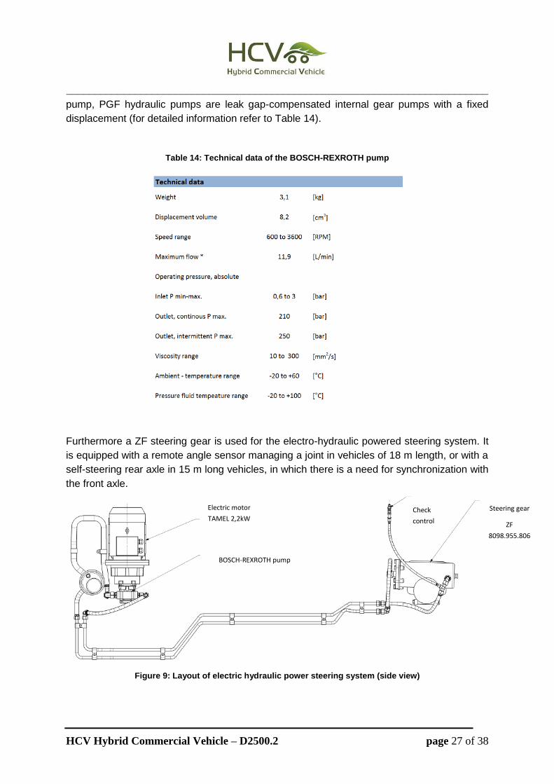
The layout of the system is presented in Figure 9. The hydraulic pump BOSCH-REXROTH
PGF2-2X/008RE01VE4 (output 11 l/min; weight 3 kg) is driven by a 3x400 VAC three phase
asynchronous motor which is powered by a 600 VDC/3x400 VAC converter. Concerning the
__________________________________________________________________________
HCV Hybrid Commercial Vehicle – D2500.2 page 27 of 38
pump, PGF hydraulic pumps are leak gap-compensated internal gear pumps with a fixed
displacement (for detailed information refer to Table 14).
Table 14: Technical data of the BOSCH-REXROTH pump
Furthermore a ZF steering gear is used for the electro-hydraulic powered steering system. It
is equipped with a remote angle sensor managing a joint in vehicles of 18 m length, or with a
self-steering rear axle in 15 m long vehicles, in which there is a need for synchronization with
the front axle.
Figure 9: Layout of electric hydraulic power steering system (side view)
Electric motor
TAMEL 2,2kW
BOSCH-REXROTH pump
PGF2-22 008RE01VE04-8CCM
Check
control
Steering gear
ZF
8098.955.806

__________________________________________________________________________
HCV Hybrid Commercial Vehicle – D2500.2 page 28 of 38
The schematic diagram of the control blocks layout of the whole system is shown in Figure
10.
Figure 10: Scheme of the electro hydraulic power steering system’s operation
Using this system outside urban areas a fuel reduction between 0.3 to 0.4 dm3/100 km could
be obtained whereas during urban drives a decrease of 1 dm3/100 km could be possible.
Assessment and Results
The electro-hydraulic powered steering system (hydraulic accumulator and electrically driven
feed pump) was compared to a standard system with a mechanical pump in identical
URBINO 12 buses in a real road test.
The emission level and fuel consumption seems to be directly dependent on the acceleration
of the vehicle. The NOx emission confirms this theory but when stopping the vehicle after 20
s its concentration increases again in both systems whereas the CO and CH levels are the
highest right after stopping. This is most likely due to an oxidation efficiency decrease of the
SCR system when vehicle is stopped.
A comparison between the average emission values for the standard and the modified
system can be found in Table 15 and Figure 11.
Table 15: Average emission results for the different systems implemented in the buses
Steering System CO2 CO NOx HC
Standard 963.5 g/km 2.6 g/km 5.5 g/km 0.0109 g/km
Electro powered 947.5 g/km 2.1 g/km 4.5 g/km 0.0037 g/km
Decrease using electrified steering 5.4 % 19.2 % 18.2 % 66.0 %

__________________________________________________________________________
HCV Hybrid Commercial Vehicle – D2500.2 page 29 of 38
Figure 11: Summary of percentage differences in average emission values of harmful compounds for the
standard bus and the bus with the modified steering system
The fuel reduction by the use of the electrically powered system was about 1.7 % and the
energy saving about 1.6 % compared to the standard system.

__________________________________________________________________________
HCV Hybrid Commercial Vehicle – D2500.2 page 30 of 38
High Power Generator
Specification
The Vanner High power generator (HVDC) has been chosen for implementation in the
demonstrator bus of the HCV project because it is efficient, very reliable, has reduced
maintenance costs and can be placed instead of a belt driven alternator or parallel to it. The
device was furthermore recommended by the hybrid system supplier. Supplier Statement:
"Allison has validated the VANNER DC/DC converter. Therefore VANNER is, at this point,
the only supplier allowed in combination with the Allison Hybrid".
The Vanner HVDC converts the available high voltage into low voltage required for the
auxiliaries of the bus.
Comparing the HVDC to a standard production alternator shows that the main benefits of
using the HVDC are: higher efficiency by about 25 – 30 %, stable DC power, precise voltage
regulation, reliable performance and reduced layout parts.
The main parameters for selecting the Vanner High power generator for the implementation
in the HCV demonstrator SOLARIS URBINO 18m Hybrid bus are presented in Table 16.
Table 16: Main parameters of the Vanner High power generator
CO2 Reduction Costs Weight Packaging and Implementation
Effort
Considerations
Potential to
reduce power
consumption by
30-60 %
compared to
mechanical one
3,400 € 34 kg
roof mounted, decoupled from
engine - no risk of thermal events,
more flexibility and efficiency;
mounting on a flat horizontal
surface not in a zero-clearance
compartment (overheating); min 4
inches distance to fan inlet and
outlet. Special cable for connection
with existing electrics needed.
Device recommended by hybrid
system supplier. Supplier
Statement: "Allison has
validated the VANNER DC/DC
converter. Therefore VANNER is,
at this point, the only supplier
allowed in combination with the
Allison Hybrid"
Assessment and Results
Compared were two different systems that can provide the electrical energy. The first one
consists of four classical alternators and the second one is equipped with the Vanner High
power DC/DC converter (for more details refer to deliverable D2400.4 [7]). The specification
of the selected solution using a highly efficient DC-DC converter is presented in Table 17.

__________________________________________________________________________
HCV Hybrid Commercial Vehicle – D2500.2 page 31 of 38
Table 17: Technical specification of the Vanner High power DC/DC converter
Parameter Value
Maximal voltage at the outlet 30 V
Maximal current at the outlet 300 A
Maximal voltage at the inlet 600 V
Maximal current at the inlet 17 A
Efficiency approx. 90%
Rotation direction clockwise
Max. rotational speed 12 000 rpm
Maximal storage temperature + 85°C
Minimal storage temperature - 40°C
Maximal operation temperature + 80°C
Min. operation temperature - 40°C
Calculation results for an average rotational speed of 900 rpm and an efficiency of 60 %
using four alternators showed a generated power of 11.2 kW for the alternator system.
For the system with the high power generator the resulting power, which is independent from
the engine speed was assumed to have an efficiency of 90 %. This leads to an electric power
obtained of 6.79 kW. This equals a reduction of the electrical energy by 4.4 kW and it
diminishes the engine load by 11.05 kW. In this case the usage of the high power generator
leads to a load reduction of 60 % (could be less for other systems). For the combustion
engine, resulting from lower energy need of the board devices of the bus, a diminished load
by approx. 30-40 % enables obtaining serious economic benefits.

__________________________________________________________________________
HCV Hybrid Commercial Vehicle – D2500.2 page 32 of 38
Electric engine cooling fan
Specification
Chosen for implementation in the demonstrator vehicle SOLARIS HURBINO 18m Hybrid was
the electrically controlled (EC) axial fan from “ebm-papst” with an integrated electric
brushless DC motor (M3G074-CF). The specification of the fan can be seen in Table 18.
Table 18: Specification of the EC fan from ebm-papst
In Table 19 the main advantages of the electrical fan compared to the standard production
one and the main reasons for choosing this specific fan can be seen. For this investigation
the standard production hydraulic driven fan system consuming about 14.4 kW was replaced
by a unit with six smaller electrical fans located on a common cooling plate (6 x 335 W as
presented on Figure 12) leading to a maximum power consumption of 2.01 kW. The details
about the performed experimental analysis can be found in deliverable D2400.4 [7].

__________________________________________________________________________
HCV Hybrid Commercial Vehicle – D2500.2 page 33 of 38
Table 19: Main parameters of the electrical fan
Component CO2 Reduction Costs Weight Packaging and
Implementation Effort
Additional
Information
ebm-papst
W3G 300 - ER
38 - 45
(Cummins
ISB 6.7 285H
+ Vossloh
Kiepe)
CO2 emission
increased by 4
%; fuel
consumption
was 4.6 % lower
in test; ev.
leading to 1.2 -
5 % for real
load conditions
2.5 kg (six
units so
around 18
kg compared
to 40 kg of
the
hydrostatic
fan)
A higher amount of
smaller electrical fans can
be packaged in a unit -
much more flexibility in
size and packaging; No
mounting limitations,
integrated brushless
engine. Smaller size and
lower weight than
hydrostatic fan.
Rotational speed of
the fan is
independent from
the one of the
engine; No hydraulic
drive assembly
(hydraulic lines,
fluid storage)-->
weight saving ;
lower operating
costs;
Figure 12: Setup of six electrical fans on the radiator
Assessment and Results
One hour measurements on the hydraulic driven fan system lead to a calculated system’s
power of 3.7 kW. On the other hand the electrical system can diminish the power
consumption by ~3.2 kW (~86 % energy saving) because it needs just around 0.5 kW for the
same experimental condition.
The emission measurements presented on Figure 13 were performed at stop bus position
(Solaris Urbino 18 Hybrid) without any additional load.

__________________________________________________________________________
HCV Hybrid Commercial Vehicle – D2500.2 page 34 of 38
Figure 13: Comparison of the average relative emissions of CO, HC, NOx, and CO2 between engines using
different types of cooling systems
The lower fuel consumption is due to the higher efficiency of energy conversion and the
possibility of controlling the air flow (potential to reduce power consumption compared to the
hydraulically driven mechanical fan solution is around 30-90 % depending on the driving
cycle). Measurements described in D2400.5 [7] result in a reduction of power consumption
by nearly 40 %. CO emission was reduced by about 13 % and the one of hydro carbons by
~8 %. On the contrary NOx emission increase by 8 % and also the CO2 emission is around 4
% higher in the hybrid vehicle as shown on figure above. The overall fuel consumption is
~4.6 % lower than for the hydraulic system due to stationary load and stop conditions. For
real load with higher frequency on transient conditions the expected reduction of fuel
consumption may be around 1.2 - 5 %.
As mentioned earlier the details on the experimental validation can be found in deliverable
D2400.4 [7].
Re
lative
un
it e
mis
sio
ns o
f C
O,
HC
,
NO
x,
CO
2 [
%]

__________________________________________________________________________
HCV Hybrid Commercial Vehicle – D2500.2 page 35 of 38
Electrified DPF system
Specifications
The main specifications of the e-DPF system are shown in Table 20. They are determined by
the primary performance requirements which are:
1. Low back-pressure
2. Sufficient soot capture efficiency
3. Primary method of regeneration (soot burning) by electrical means, having power
supply requirements compatible with the hybrid vehicle electrical power availability.
4. Regeneration control and flexibility
5. Energy requirement for regeneration that is 50 % or less compared to the non-
electrical alternative.
Table 20: Main specification of the e–DPF system
Parameter Value Unit
Overall volume (maximum) 12 Liters
Filtration area 0.7 m2
Filtration efficiency 90 % -
Exhaust flow rate 3000 L/m
Power input (max) 3.5 kW
Current draw (max) 90 A
Operating voltage 24 - 30 V
Duration of electric power pulses to the e-DPF
0.2 - 2 minutes
Clean back pressure (max) 5 mbar
Loaded back pressure (max) 90 mbar
The main advantages of the electrically heated diesel particle filter compared to the standard
production heated by additional fuel injection and the main reasons for choosing this specific
material for the filter are presented in Table 21.

__________________________________________________________________________
HCV Hybrid Commercial Vehicle – D2500.2 page 36 of 38
Table 21: Main parameters of the selected e-DPF
Type CO2 Reduction Costs Weight Additional Information Decision
sintered
metal
felt/flee
ce
(fibrous)
If electrified directly,
potential 50% reduction
in regeneration energy
due to direct thermal
energy deposition
through tight soot
contact. Low thermal
mass DPF wall allows the
use of short (5 - 50 sec.)
pulses for regeneration.
Very good
operating costs,
good
maintenance
cost.
Acceptability of
capital costs
proven by small
scale
commercial
deployment.
High intrinsic
density of metal
but high
porosity wall.
Material and
module
packaging
weight of 4 kg
for a light truck
DPF system.
Available fleece strip
(resistance) values easilly
compatible with 24-48 V and
currents available on-board
light truck or heavy duty
hybrids. Modular concept is
exploited to allow reduce
electrical energy needed for
regeneration.
Feasibility of regeneration by
direct electrification already
proven. Fibrous structures
are closer to filtration
efficiency vs. pressure drop
optimum. Advanced
formulation of DPF-targetted
metal fiber fleece available
and in production. Proof-of-
concept with older
formulation (HiCEPs Project)
showed very low energy
requirement for
regeneration.
DPF filter element module design specification
The electrified Diesel particulate filter (DPF) system to be implemented is for off-vehicle
testing (test cell) in accordance with the work plan of the project. The multiple modules
consisting of 6-10 rectangular filtrating elements can be powered and regenerated
separately. Their design should enable stacking multiple in the canister assembly of the
diesel particulate filter. The filtration material consists of a continuous strip of metal fibers.
Structural connection and electrical contact points are collocated and positioned on the filter
module in order to permit low voltage electrical connections (<50 V) by direct feed-through
the e-DPF canister (steel 316). Further details regarding the material specification, filter
design can be found in deliverable D2400.4 [7].

__________________________________________________________________________
HCV Hybrid Commercial Vehicle – D2500.2 page 37 of 38
Conclusion
The simulations performed in the work package WP2100 showed that a fuel reduction
potential of 6.0 % for the hybrid bus system is available and one of 19.7 % for the
hybridization of the delivery truck implementing the electrified auxiliaries presented in this
deliverable. The final report D2100.5 [8] of the work package WP2100 defined all the
minimum required electrified component specification to reach these goals.
This report shows that there are components available on the market or as prototype which
can be implemented in the two demonstrator vehicles and deliver the expected fuel
consumption reduction.
Furthermore it can be concluded that the partners have developed, implemented and tested
the components required to reach the expected fuel consumption reduction for the two
demonstrator vehicles: SOLARIS URBINO 18m Hybrid bus and IVECO Daily Hybrid delivery
truck.
The main information on these components has been collected and presented in this report.

__________________________________________________________________________
HCV Hybrid Commercial Vehicle – D2500.2 page 38 of 38
References
[1] HCV Report; HYBRID COMMERCIAL VEHICLE (HCV) DELIVERABLE D2200.2,
DETAILED SPECIFICATIONS OF AUXILIARIES FOR E-A/C (CRF), E-
COMPRESSOR AND E-HEATING (SOLARIS), May 2013
[2] HCV Report; HYBRID COMMERCIAL VEHICLE (HCV) DELIVERABLE D2200.4,
AUXILIARIES_EXPERIMENTALY_VALIDATED_AND_READY_FOR_IMPLEMENTA
TION (SOLARIS), June 2013
[3] HCV Report; HYBRID COMMERCIAL VEHICLE (HCV) DELIVERABLE D2400.1,
TECHNOLOGY EVALUATION REPORT FOR AUXILIARIES FOR ELECTRICAL
FAN, HIGH POWER GENERATOR (SOLARIS), May 2013
[4] HCV Report; HYBRID COMMERCIAL VEHICLE (HCV) DELIVERABLE D2400.5,
TECHNOLOGY EVALUATION REPORT FOR DIESEL ENGINE
AFTERTREATMENT SYSTEM (CERTH), April 2013
[5] HCV Report; HYBRID COMMERCIAL VEHICLE (HCV) DELIVERABLE D2300.2,
DETAILED SPECIFICATIONS OF AUXILIARIES FOR ELECTRICALLY POWERED
STEERING SERVO (SOLARIS) AND ELECTRICAL ACTUATED MECHANICAL
BRAKES (CRF), April 2013
[6] HCV Report; HYBRID COMMERCIAL VEHICLE (HCV) DELIVERABLE D2300.4,
AUXILIARIES EXPERIMENTALLY VALIDATED AND READY FOR
IMPLEMENTATION (CRF, SOLARIS), May 2013
[7] HCV Report; HYBRID COMMERCIAL VEHICLE (HCV) DELIVERABLE D2400.4,
AUXILIARIES EXPERIMENTALLY VALIDATED AND READY FOR
IMPLEMENTATION (SOLARIS), May 2013
[8] HCV Report; HYBRID COMMERCIAL VEHICLE (HCV) DELIVERABLE D2100.5,
SYSTEM REQUIREMENTS AND SPECIFICATIONS (AVL), December 2011
[8] HCV Report; HYBRID COMMERCIAL VEHICLE (HCV) DELIVERABLE D2500.1,
DECISION MATRIX (AVL), June 2013