hybrid electrochemical hydrogen/metal hydride compressionhybrid electrochemical hydrogen/metal...
TRANSCRIPT
Hybrid Electrochemical Hydrogen/Metal Hydride Compression
Scott Greenway (PI), Martin Sulic, Aaron Wilber, Ted Motyka (GWE)
Bruce Hardy, Anna d’Entremont (SRNL)
George Roberts, Phillip Baker, Daryl Ludlow, Trent Molter (SI)
Claudio Corgnale (GWE) - Presenter
June 14, 2018 Project ID: PD137
This presentation does not contain any proprietary, confidential, or otherwise restricted information
2
• Hydrogen Delivery barriers• Cost of high pressure large scale
hydrogen compression systems• Efficiency of large scale compression
systems• Reliability of high pressure large
scale compression systems
• Project Start Date: 10/01/16• Project End Date: 09/30/19• Total Project Budget: $3750K
• Total Recipient Share: $752K• Total Federal Share: $2998K• Total DOE Funds Phase 1*: $1415K
* Phase 1 (18 months): end date 3/31/18
Timeline and Budget Barriers
• Savannah River National Laboratory (SRNL)
• Sustainable Innovations (SI)• Greenway Energy (GWE) - lead
Partners (funded)
Overview
3
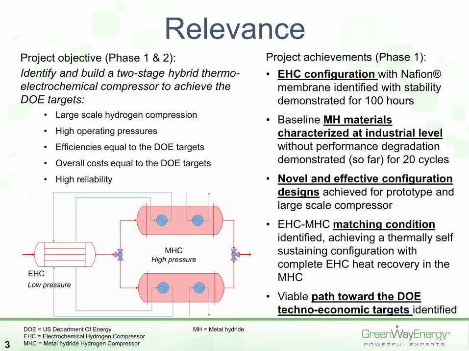
Project objective (Phase 1 & 2): Identify and build a two-stage hybrid thermo-electrochemical compressor to achieve the DOE targets:
• Large scale hydrogen compression
• High operating pressures
• Efficiencies equal to the DOE targets
• Overall costs equal to the DOE targets
• High reliability
Relevance
DOE = US Department Of Energy MH = Metal hydrideEHC = Electrochemical Hydrogen CompressorMHC = Metal hydride Hydrogen Compressor
EHC
MHC
Low pressure
High pressure
Project achievements (Phase 1):• EHC configuration with Nafion®
membrane identified with stability demonstrated for 100 hours
• Baseline MH materials characterized at industrial level without performance degradation demonstrated (so far) for 20 cycles
• Novel and effective configuration designs achieved for prototype and large scale compressor
• EHC-MHC matching conditionidentified, achieving a thermally self sustaining configuration with complete EHC heat recovery in the MHC
• Viable path toward the DOE techno-economic targets identified
4
Approach
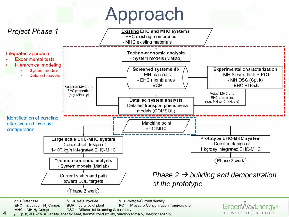
Integrated approach • Experimental tests• Hierarchical modeling
• System models• Detailed models
Identification of baseline effective and low cost configuration
db = Database MH = Metal hydride VI = Voltage-Current densityEHC = Electroch. H2 Compr. BOP = balance of plant PCT = Pressure-Concentration-TemperatureMHC = MH H2 Compr. DSC = Differential Scanning Calorimetryρ, Cp, k, ∆H, wt% = Density, specific heat, thermal conductivity, reaction enthalpy, weight capacity
Project Phase 1
Phase 2 building and demonstration of the prototype
5
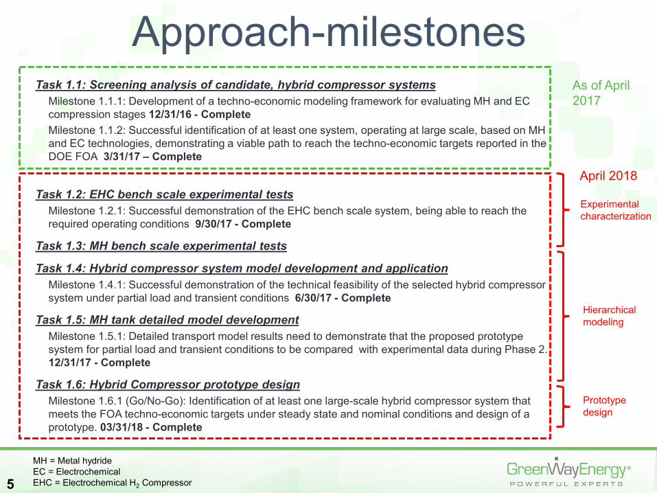
Approach-milestonesTask 1.1: Screening analysis of candidate, hybrid compressor systems
Milestone 1.1.1: Development of a techno-economic modeling framework for evaluating MH and EC compression stages 12/31/16 - CompleteMilestone 1.1.2: Successful identification of at least one system, operating at large scale, based on MH and EC technologies, demonstrating a viable path to reach the techno-economic targets reported in the DOE FOA 3/31/17 – Complete
Task 1.2: EHC bench scale experimental testsMilestone 1.2.1: Successful demonstration of the EHC bench scale system, being able to reach the required operating conditions 9/30/17 - Complete
Task 1.3: MH bench scale experimental tests
Task 1.4: Hybrid compressor system model development and applicationMilestone 1.4.1: Successful demonstration of the technical feasibility of the selected hybrid compressor system under partial load and transient conditions 6/30/17 - Complete
Task 1.5: MH tank detailed model development Milestone 1.5.1: Detailed transport model results need to demonstrate that the proposed prototype system for partial load and transient conditions to be compared with experimental data during Phase 2. 12/31/17 - Complete
Task 1.6: Hybrid Compressor prototype designMilestone 1.6.1 (Go/No-Go): Identification of at least one large-scale hybrid compressor system that meets the FOA techno-economic targets under steady state and nominal conditions and design of a prototype. 03/31/18 - Complete
MH = Metal hydrideEC = ElectrochemicalEHC = Electrochemical H2 Compressor
As of April 2017
April 2018
Experimental characterization
Hierarchical modeling
Prototype design
6
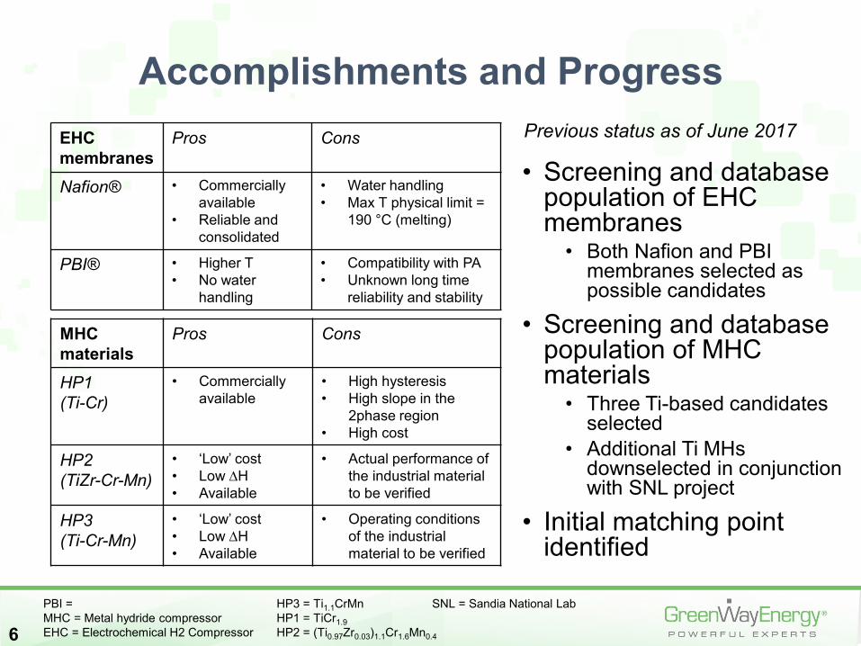
Accomplishments and Progress
• Screening and database population of EHC membranes
• Both Nafion and PBI membranes selected as possible candidates
• Screening and database population of MHC materials
• Three Ti-based candidates selected
• Additional Ti MHs downselected in conjunction with SNL project
• Initial matching point identified
EHC membranes
Pros Cons
Nafion® • Commercially available
• Reliable and consolidated
• Water handling• Max T physical limit =
190 °C (melting)
PBI® • Higher T• No water
handling
• Compatibility with PA• Unknown long time
reliability and stability
MHC materials
Pros Cons
HP1(Ti-Cr)
• Commercially available
• High hysteresis• High slope in the
2phase region• High cost
HP2 (TiZr-Cr-Mn)
• ‘Low’ cost• Low ∆H• Available
• Actual performance of the industrial material to be verified
HP3 (Ti-Cr-Mn)
• ‘Low’ cost• Low ∆H• Available
• Operating conditions of the industrial material to be verified
Previous status as of June 2017
PBI = HP3 = Ti1.1CrMn SNL = Sandia National LabMHC = Metal hydride compressor HP1 = TiCr1.9EHC = Electrochemical H2 Compressor HP2 = (Ti0.97Zr0.03)1.1Cr1.6Mn0.4
7
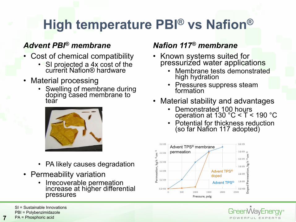
Advent PBI® membrane • Cost of chemical compatibility
• SI projected a 4x cost of the current Nafion® hardware
• Material processing• Swelling of membrane during
doping cased membrane to tear
• PA likely causes degradation• Permeability variation
• Irrecoverable permeation increase at higher differential pressures
Nafion 117® membrane• Known systems suited for
pressurized water applications• Membrane tests demonstrated
high hydration• Pressures suppress steam
formation• Material stability and advantages
• Demonstrated 100 hours operation at 130 °C < T < 190 °C
• Potential for thickness reduction (so far Nafion 117 adopted)
High temperature PBI® vs Nafion®
Doped
Advent TPS® membrane permeation
Advent TPS®
Advent TPS®
doped
SI = Sustainable InnovationsPBI = PolybenzimidazolePA = Phosphoric acid
8
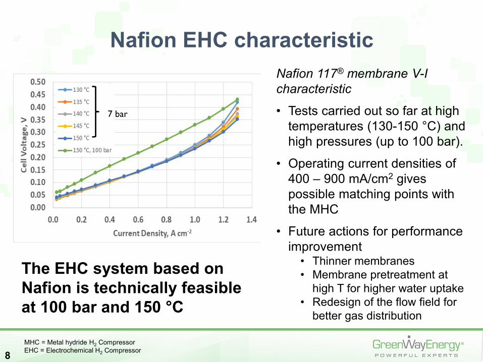
Nafion 117® membrane V-I characteristic
• Tests carried out so far at high temperatures (130-150 °C) and high pressures (up to 100 bar).
• Operating current densities of 400 – 900 mA/cm2 gives possible matching points with the MHC
• Future actions for performance improvement
• Thinner membranes • Membrane pretreatment at
high T for higher water uptake• Redesign of the flow field for
better gas distribution
Nafion EHC characteristic
7 bar
The EHC system based on Nafion is technically feasible at 100 bar and 150 °C
MHC = Metal hydride H2 Compressor EHC = Electrochemical H2 Compressor
9
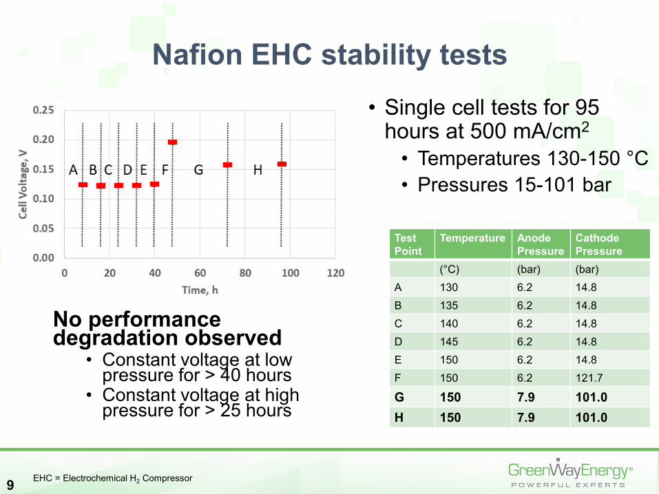
• Single cell tests for 95 hours at 500 mA/cm2
• Temperatures 130-150 °C• Pressures 15-101 bar
Nafion EHC stability tests
Test Point
Temperature Anode Pressure
Cathode Pressure
(°C) (bar) (bar)A 130 6.2 14.8B 135 6.2 14.8C 140 6.2 14.8D 145 6.2 14.8E 150 6.2 14.8F 150 6.2 121.7
G 150 7.9 101.0H 150 7.9 101.0
No performance degradation observed
• Constant voltage at low pressure for > 40 hours
• Constant voltage at high pressure for > 25 hours
EHC = Electrochemical H2 Compressor
10
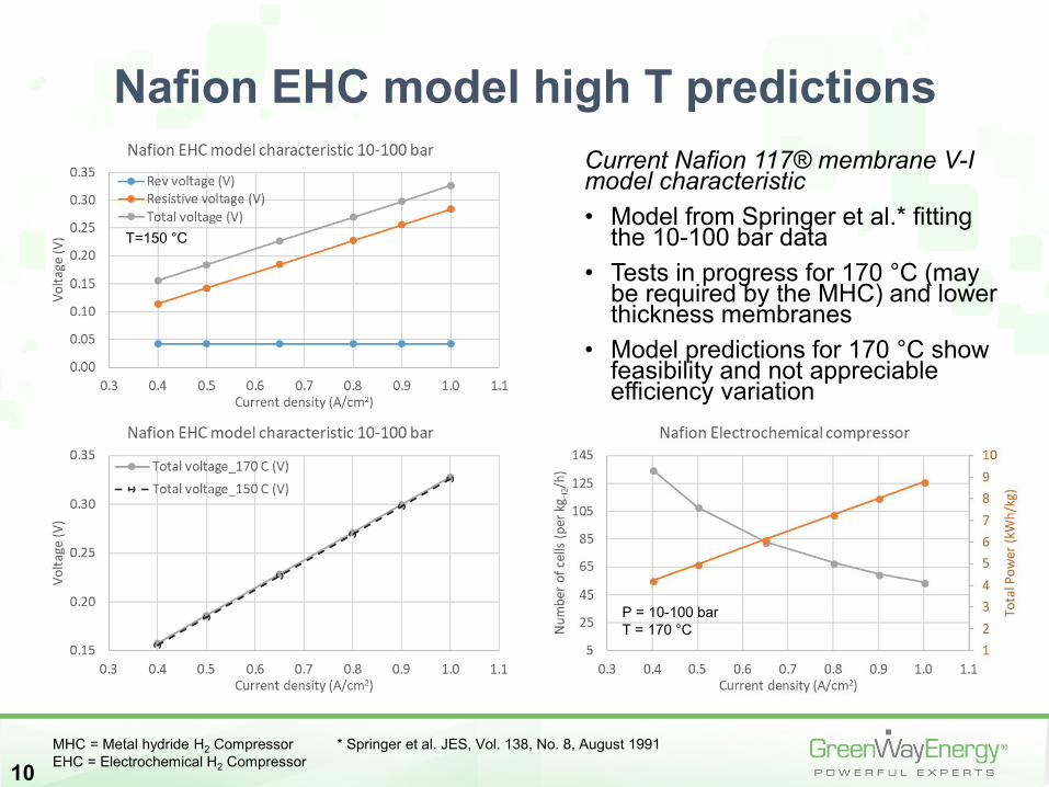
Current Nafion 117® membrane V-I model characteristic• Model from Springer et al.* fitting
the 10-100 bar data• Tests in progress for 170 °C (may
be required by the MHC) and lower thickness membranes
• Model predictions for 170 °C show feasibility and not appreciable efficiency variation
Nafion EHC model high T predictions
T=150 °C
P = 10-100 barT = 170 °C
MHC = Metal hydride H2 Compressor * Springer et al. JES, Vol. 138, No. 8, August 1991 EHC = Electrochemical H2 Compressor
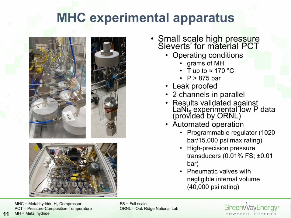
• Small scale high pressure Sieverts’ for material PCT
• Operating conditions • grams of MH • T up to ≈ 170 °C • P > 875 bar
• Leak proofed• 2 channels in parallel• Results validated against
LaNi5 experimental low P data (provided by ORNL)
• Automated operation• Programmable regulator (1020
bar/15,000 psi max rating)• High-precision pressure
transducers (0.01% FS; ±0.01 bar)
• Pneumatic valves with negligible internal volume (40,000 psi rating)
11
MHC experimental apparatus
MHC = Metal hydride H2 Compressor FS = Full scalePCT = Pressure-Composition-Temperature ORNL = Oak Ridge National LabMH = Metal hydride
22 °C50 °C
80 °C110 °C130 °C170 °C
12
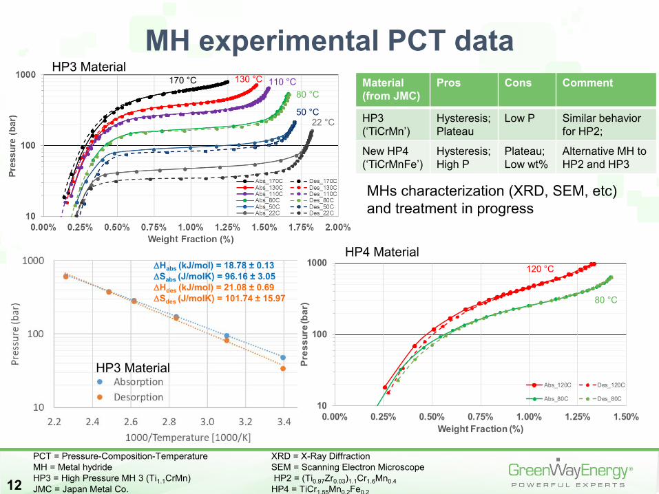
MH experimental PCT data
PCT = Pressure-Composition-Temperature XRD = X-Ray DiffractionMH = Metal hydride SEM = Scanning Electron MicroscopeHP3 = High Pressure MH 3 (Ti1.1CrMn) HP2 = (Ti0.97Zr0.03)1.1Cr1.6Mn0.4JMC = Japan Metal Co. HP4 = TiCr1.55Mn0.2Fe0.2
HP3 Material
∆Habs (kJ/mol) = 18.78 ± 0.13∆Sabs (J/molK) = 96.16 ± 3.05∆Hdes (kJ/mol) = 21.08 ± 0.69∆Sdes (J/molK) = 101.74 ± 15.97
10
100
1000
0.00% 0.25% 0.50% 0.75% 1.00% 1.25% 1.50%
Pres
sure
(bar
)
Weight Fraction (%)
Abs_120C Des_120C
Abs_80C Des_80C
HP3 Material
80 °C
120 °C
HP4 Material
Material (from JMC)
Pros Cons Comment
HP3(‘TiCrMn’)
Hysteresis;Plateau
Low P Similar behavior for HP2;
New HP4 (‘TiCrMnFe’)
Hysteresis;High P
Plateau;Low wt%
Alternative MH to HP2 and HP3
MHs characterization (XRD, SEM, etc) and treatment in progress
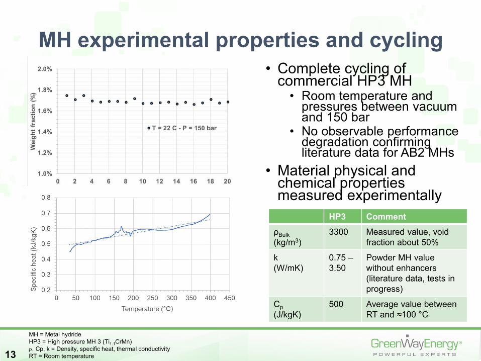
• Complete cycling of commercial HP3 MH
• Room temperature and pressures between vacuum and 150 bar
• No observable performance degradation confirming literature data for AB2 MHs
• Material physical and chemical properties measured experimentally
13
MH experimental properties and cycling
HP3 CommentρBulk(kg/m3)
3300 Measured value, void fraction about 50%
k (W/mK)
0.75 –3.50
Powder MH value without enhancers (literature data, tests in progress)
Cp(J/kgK)
500 Average value between RT and ≈100 °C
MH = Metal hydrideHP3 = High pressure MH 3 (Ti1.1CrMn)ρ, Cp, k = Density, specific heat, thermal conductivityRT = Room temperature
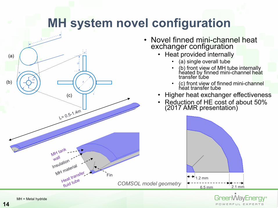
• Novel finned mini-channel heat exchanger configuration
• Heat provided internally • (a) single overall tube • (b) front view of MH tube internally
heated by finned mini-channel heat transfer tube
• (c) front view of finned mini-channel heat transfer tube
• Higher heat exchanger effectiveness • Reduction of HE cost of about 50%
(2017 AMR presentation)
14
MH system novel configurationL
Dt
tt
d
Lf
tf
t
(a)
(b)
(c)
Fin
COMSOL model geometry1.2 mm
6.5 mm 2.1 mm
(a)
(b)
(c)
MH = Metal hydride
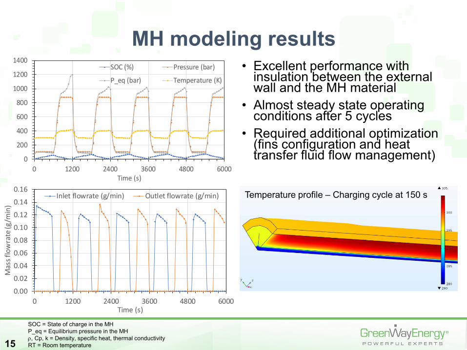
• Excellent performance with insulation between the external wall and the MH material
• Almost steady state operating conditions after 5 cycles
• Required additional optimization (fins configuration and heat transfer fluid flow management)
15
MH modeling results
0
200
400
600
800
1000
1200
1400
0 1200 2400 3600 4800 6000Time (s)
SOC (%) Pressure (bar)
P_eq (bar) Temperature (K)
SOC = State of charge in the MHP_eq = Equilibrium pressure in the MHρ, Cp, k = Density, specific heat, thermal conductivityRT = Room temperature
0.00
0.02
0.04
0.06
0.08
0.10
0.12
0.14
0.16
0 1200 2400 3600 4800 6000
Mas
s flo
wra
te (g
/min
)
Time (s)
Inlet flowrate (g/min) Outlet flowrate (g/min) Temperature profile – Charging cycle at 150 s
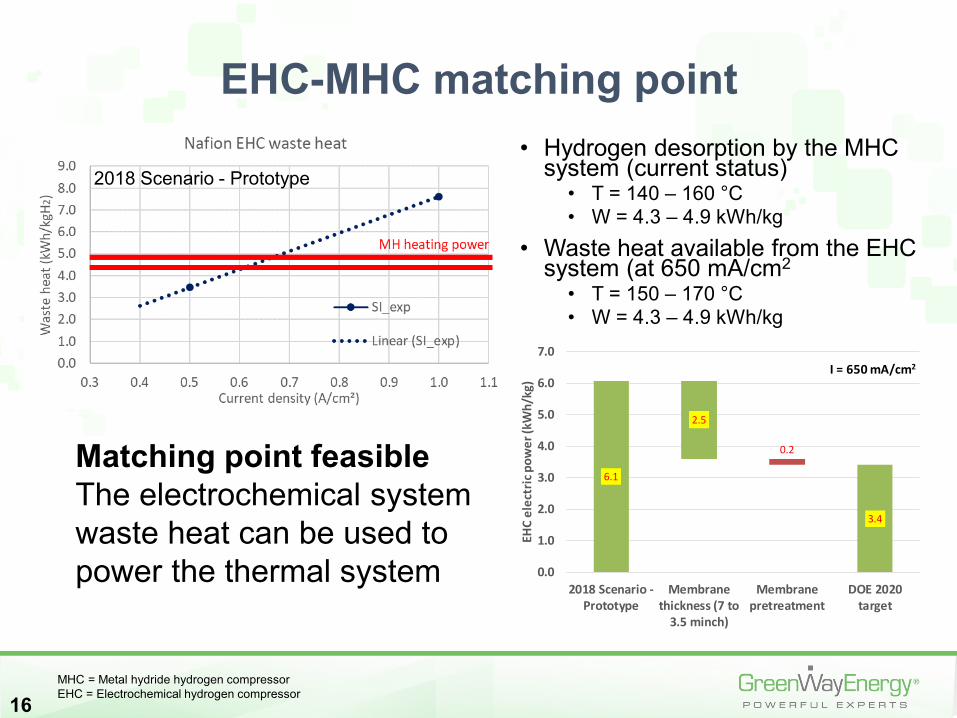
• Hydrogen desorption by the MHC system (current status)
• T = 140 – 160 °C• W = 4.3 – 4.9 kWh/kg
• Waste heat available from the EHC system (at 650 mA/cm2
• T = 150 – 170 °C • W = 4.3 – 4.9 kWh/kg
16
EHC-MHC matching point
Matching point feasibleThe electrochemical system waste heat can be used to power the thermal system
MHC = Metal hydride hydrogen compressorEHC = Electrochemical hydrogen compressor
0.2
6.1
2.5
3.4
0.0
1.0
2.0
3.0
4.0
5.0
6.0
7.0
2018 Scenario -Prototype
Membranethickness (7 to
3.5 minch)
Membranepretreatment
DOE 2020target
EHC
elec
tric
pow
er (k
Wh/
kg)
I = 650 mA/cm2
2018 Scenario - Prototype
17
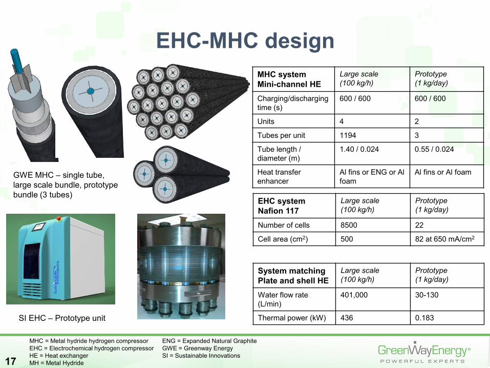
EHC-MHC designMHC systemMini-channel HE
Large scale (100 kg/h)
Prototype (1 kg/day)
Charging/discharging time (s)
600 / 600 600 / 600
Units 4 2
Tubes per unit 1194 3
Tube length / diameter (m)
1.40 / 0.024 0.55 / 0.024
Heat transfer enhancer
Al fins or ENG or Al foam
Al fins or Al foam
EHC systemNafion 117
Large scale (100 kg/h)
Prototype (1 kg/day)
Number of cells 8500 22
Cell area (cm2) 500 82 at 650 mA/cm2
System matchingPlate and shell HE
Large scale (100 kg/h)
Prototype (1 kg/day)
Water flow rate (L/min)
401,000 30-130
Thermal power (kW) 436 0.183SI EHC – Prototype unit
Insulation
Pressure vessel
External insulation
GWE MHC – single tube, large scale bundle, prototype bundle (3 tubes)
MHC = Metal hydride hydrogen compressor ENG = Expanded Natural GraphiteEHC = Electrochemical hydrogen compressor GWE = Greenway EnergyHE = Heat exchanger SI = Sustainable InnovationsMH = Metal Hydride
18
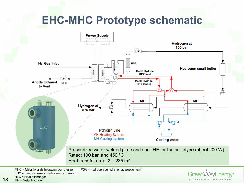
EHC-MHC Prototype schematic
Pressurized water welded plate and shell HE for the prototype (about 200 W)Rated: 100 bar, and 450 °CHeat transfer area: 2 – 235 m2
MHC = Metal hydride hydrogen compressor PSA = Hydrogen dehydration adsorption unitEHC = Electrochemical hydrogen compressorHEX = Heat exchangerMH = Metal Hydride
PrototypePrototype
19
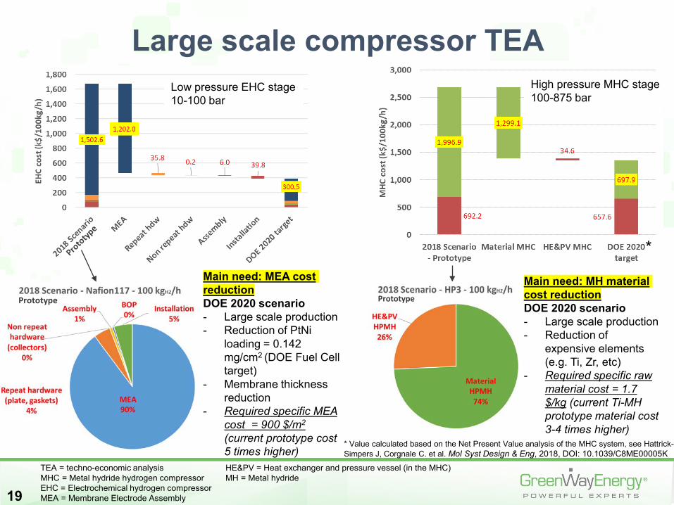
Large scale compressor TEA Low pressure EHC stage10-100 bar
Main need: MEA cost reductionDOE 2020 scenario- Large scale production- Reduction of PtNi
loading = 0.142 mg/cm2 (DOE Fuel Cell target)
- Membrane thickness reduction
- Required specific MEA cost = 900 $/m2
(current prototype cost 5 times higher)
High pressure MHC stage100-875 bar
Main need: MH material cost reductionDOE 2020 scenario- Large scale production- Reduction of
expensive elements (e.g. Ti, Zr, etc)
- Required specific raw material cost = 1.7 $/kg (current Ti-MH prototype material cost 3-4 times higher)
TEA = techno-economic analysis HE&PV = Heat exchanger and pressure vessel (in the MHC)MHC = Metal hydride hydrogen compressor MH = Metal hydrideEHC = Electrochemical hydrogen compressorMEA = Membrane Electrode Assembly
*
* Value calculated based on the Net Present Value analysis of the MHC system, see Hattrick-Simpers J, Corgnale C. et al. Mol Syst Design & Eng, 2018, DOI: 10.1039/C8ME00005K
20
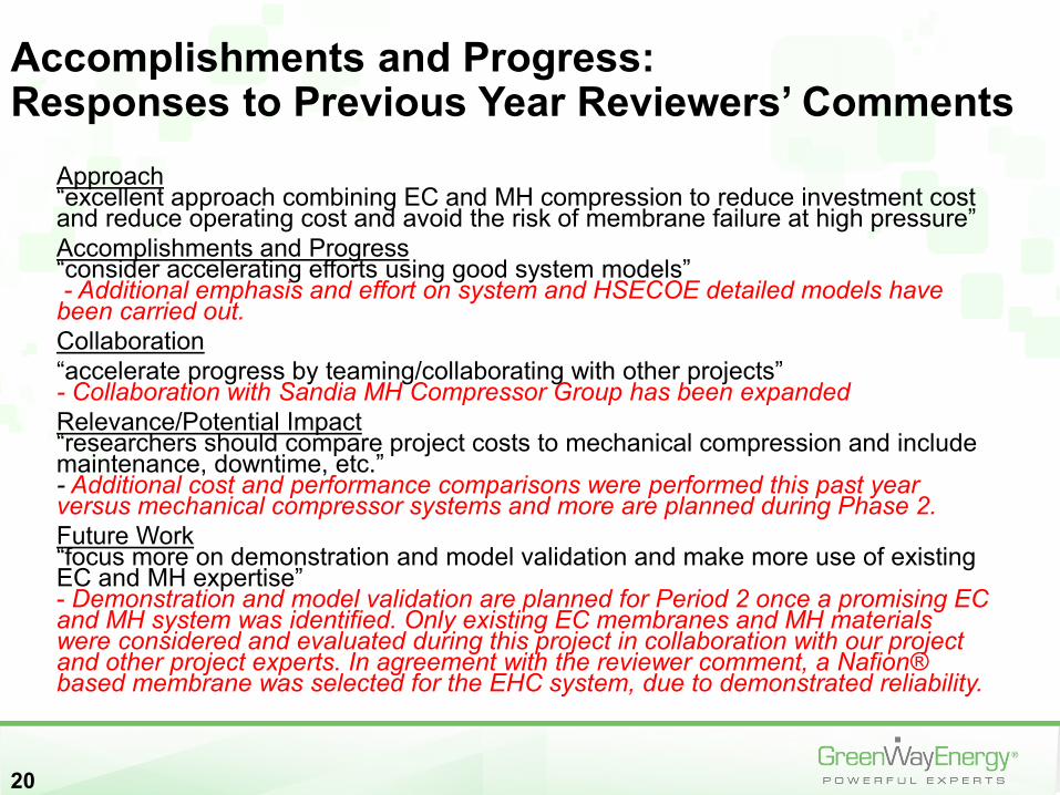
Approach“excellent approach combining EC and MH compression to reduce investment cost and reduce operating cost and avoid the risk of membrane failure at high pressure”Accomplishments and Progress“consider accelerating efforts using good system models”- Additional emphasis and effort on system and HSECOE detailed models have
been carried out.Collaboration“accelerate progress by teaming/collaborating with other projects”- Collaboration with Sandia MH Compressor Group has been expandedRelevance/Potential Impact“researchers should compare project costs to mechanical compression and include maintenance, downtime, etc.”- Additional cost and performance comparisons were performed this past year versus mechanical compressor systems and more are planned during Phase 2.Future Work“focus more on demonstration and model validation and make more use of existing EC and MH expertise”- Demonstration and model validation are planned for Period 2 once a promising EC and MH system was identified. Only existing EC membranes and MH materials were considered and evaluated during this project in collaboration with our project and other project experts. In agreement with the reviewer comment, a Nafion® based membrane was selected for the EHC system, due to demonstrated reliability.
Accomplishments and Progress: Responses to Previous Year Reviewers’ Comments
21
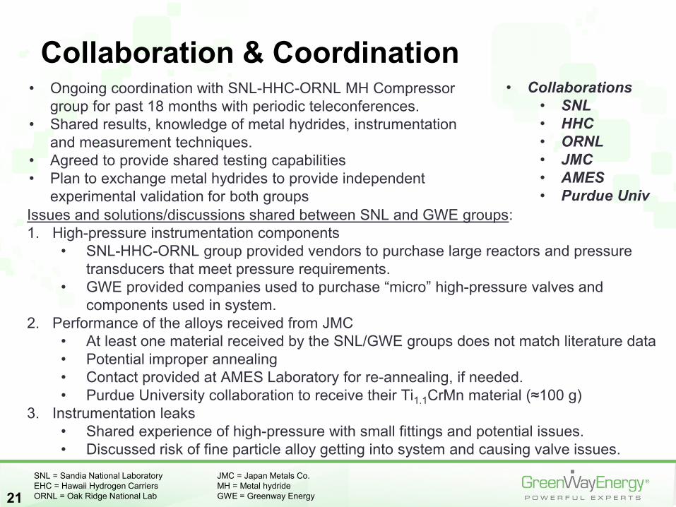
Collaboration & Coordination• Ongoing coordination with SNL-HHC-ORNL MH Compressor
group for past 18 months with periodic teleconferences.• Shared results, knowledge of metal hydrides, instrumentation
and measurement techniques.• Agreed to provide shared testing capabilities • Plan to exchange metal hydrides to provide independent
experimental validation for both groupsIssues and solutions/discussions shared between SNL and GWE groups:1. High-pressure instrumentation components
• SNL-HHC-ORNL group provided vendors to purchase large reactors and pressure transducers that meet pressure requirements.
• GWE provided companies used to purchase “micro” high-pressure valves and components used in system.
2. Performance of the alloys received from JMC • At least one material received by the SNL/GWE groups does not match literature data• Potential improper annealing• Contact provided at AMES Laboratory for re-annealing, if needed.• Purdue University collaboration to receive their Ti1.1CrMn material (≈100 g)
3. Instrumentation leaks• Shared experience of high-pressure with small fittings and potential issues.• Discussed risk of fine particle alloy getting into system and causing valve issues.
• Collaborations• SNL• HHC• ORNL • JMC• AMES • Purdue Univ
SNL = Sandia National Laboratory JMC = Japan Metals Co.EHC = Hawaii Hydrogen Carriers MH = Metal hydrideORNL = Oak Ridge National Lab GWE = Greenway Energy

Remaining Challenges and Barriers• EHC system
• Demonstration of Nafion MEA performance at T > 150°C (possibly required by the MHC system)
• Enhanced MEA configuration demonstration (reduced thickness, reduced Pt loading, etc)
• MHC system• MH material demonstration, showing proper hydrogen desorption at
875 bar and 130-150 °C at feasible material weight capacities• Interfaced plate and shell heat exchanger
• Demonstration of proper heat transfer between the EHC and the heat transfer fluid at the required conditions
• Prototype BOP design (e.g. water management equipment, buffer tanks)
• Prototype assembling and demonstration• Transport model validation against prototype experimental data• System optimization and enhancement to meet the DOE techno-
economic targets
22MHC = Metal Hydride Compressor BOP = Balance of PlantEHC = Electrochemical Hydrogen Compressor MH = Metal hydrideMEA = Membrane Electrode Assembly GWE = Greenway Energy
23
• Assembling and demonstration of the prototype, hybrid compressor system• Tasks 2.1 and 2.2 – Milestone (3/30/19): Successful demonstration of the
prototype hybrid compressor system, showing a performance being at least equal to 60% of the efficiency targets (compression work ≤ 2.3 kWh/kg) reported in the FOA for steady state nominal conditions and 40% of the efficiency targets (compression work ≤ 3.5 kWh/kg) for transient conditions.
• Detailed model update and validation against the prototype data• Tasks 2.3 and 2.4 – Milestone (6/30/19): Successful validation of the detailed
MH tank model. Temperature, pressure and concentration numerical data will be compared with the corresponding experimental data for at least 3 points inside each MH material with a maximum difference of 10%. The data will be compared for full load conditions and for one partial load case, both under steady state conditions and start up and shut down operation.
• Optimization of the hybrid compressor system • Task 2.5 – Milestone (9/30/19): Successful identification of an improved
performance full-scale system (integrating the ECH, MH and internal heat recovery system) that can achieve all the FOA requirements, except the compression specific work, which will be equal to the isothermal compression work, at the same operating temperatures and pressures. Thus, the improved full scale system will meet: (1) capacity of hydrogen flow rates of at least 100 kg/h; (2) outlet pressures ≥875 bar; (3) compression work and capital costs ≤ to that described in the DOE Hydrogen Delivery MYRD&D; (4) reliability of 80%.
Proposed Future Work
Any proposed future work is subject to change based on funding levels

Technology Transfer Activities
• Invention disclosure and patent opportunities being considered for detailed design of metal hydride heat exchange configuration.
• Additional partnering and funding opportunities being pursued for the development of a small-scale hybrid compressor system for possible near-term hydrogen and fuel cell applications.
24
25
• EHC stage• High temperature membranes were selected so that waste heat from the
EHC stage can be used to drive the MHC stage.• Nafion 117 was selected as the baseline membrane and evaluated at high T
(150 °C) & high P (100 bar) with promising results for 100 hours.• MHC stage
• HP2 and HP3 MH materials (TiCrMn type) were selected as the best candidate materials based on their operating conditions, cost and availability.
• HP3 was downselected as the first candidate MH• The performance of new MH vessel design, showing substantial
performance and cost improvement over standard shell and tube designs, was modeled and successfully verified.
• EHC-MHC matching• Nafion 117 operating at high temperatures (>120 °C) found to have suitable waste
heat to drive the MH stage, identifying a thermally self sustaining configuration• Large scale and prototype scale EHC and MHC
• Initial design identified for the prototype and large scale configurations• EHC-MHC TEA
• The TEA of the new hybrid integrated system identified the current techno-economic performance of the system and a viable path to reach the DOE targets
Summary

26
Technical Back-Up Slides
10
100
1000
10000
2.2 2.4 2.6 2.8 3.0 3.2 3.4 3.6
Pres
sure
(bar
)
1000/Temperature [1000/K]
Our Exp AbsorptionOur Exp DesorptionCao et al IJHE,2015- Absorption
27
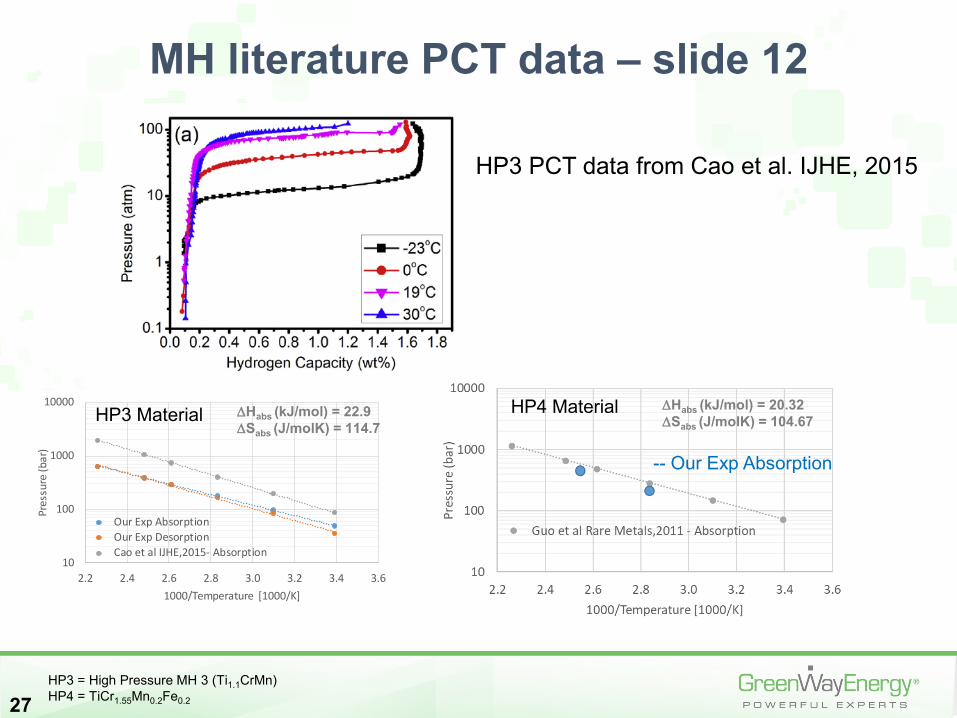
MH literature PCT data – slide 12
HP3 = High Pressure MH 3 (Ti1.1CrMn)HP4 = TiCr1.55Mn0.2Fe0.2
∆Habs (kJ/mol) = 22.9∆Sabs (J/molK) = 114.7
HP3 Material HP4 Material
-- Our Exp Absorption
∆Habs (kJ/mol) = 20.32∆Sabs (J/molK) = 104.67
HP3 PCT data from Cao et al. IJHE, 2015
28
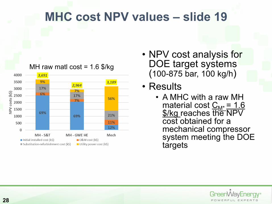
MHC cost NPV values – slide 19
MH raw matl cost = 1.6 $/kg• NPV cost analysis for
DOE target systems (100-875 bar, 100 kg/h)
• Results• A MHC with a raw MH
material cost CM* = 1.6 $/kg reaches the NPV cost obtained for a mechanical compressor system meeting the DOE targets