hybrid image coding based on partial fractal mappingz70wang/publications/spic00.pdf · represented...
TRANSCRIPT

Signal Processing: Image Communication 15 (2000) 767}779
Hybrid image coding based on partial fractal mapping
Zhou Wang!, David Zhang",*, Yinglin Yu#
!Department of Electrical and Computer Engineering, University of Texas at Austin, Austin, USA"Department of Computing, Hong Kong Polytechnic University, Hong Kong
#Department of Electronic and Communication Engineering, South China University of Technology, Guangzhou,People's Republic of China
Received 4 May 1998
Abstract
The fractal image compression technique models a natural image using a contractive mapping called fractal mappingin the image space. In this paper, we demonstrate that the fractal image coding algorithm is compatible with other imagecoding methods. In other words, we can encode only part of the image using fractal technique and model the remainingpart using other algorithms. According to such an idea, a new mapping in the image space called partial fractal mappingis proposed. Furthermore, a general framework of fractal-based hybrid image coding encoding/decoding systems ispresented. The framework provides us with much #exibility for real implementations. Many di!erent hybrid imagecoding schemes can be derived from it. Finally, a new hybrid image coding scheme is proposed where non-fractal codedregions are used to help the encoding of fractal coded regions. Experiments show that the proposed system performsbetter than the quadtree-based fractal image coding algorithm and the JPEG image compression standard at highcompression ratios larger than 30. ( 2000 Elsevier Science B.V. All rights reserved.
Keywords: Image coding; Fractal; Data compression; Hybrid system
RM the M-dimensional Cartesian product ofthe real numbers
/, t, h images (or elements in RM)d.!9
the d.!9
metric of two elements in RM
d2
the d2
metric of two elements in RM
X the set of sample point indexes in a signalW basic fractal mapping=P partial fractal mapping
1. Introduction
The concept of fractal was introduced by Man-delbrot [8] as an alternative to the traditional
*Corresponding author.
Euclidean geometry mainly for dealing with shapesgenerated by nature. In recent years, the interest ofapplying this theory has been steadily growing.A recent trend in computer graphics and imageprocessing has been to use iterated function system(IFS) to generate and describe both man-made frac-tal-like structures and natural images. Barnsleyet al. were the "rst to present the concept of fractalimage compression using IFS [1]. A fully auto-matic image compression algorithm for real-worldgray scale images called fractal block coding (FBC)was proposed by Jacquin [4,5]. Jacquin's algorithmhas been studied, re"ned and improved in recentyears, many important research results on thistopic are collected in Fisher's book [3]. As Jacquinindicated in [5], the main point of FBC is that it
0923-5965/00/$ - see front matter ( 2000 Elsevier Science B.V. All rights reserved.PII: S 0 9 2 3 - 5 9 6 5 ( 9 9 ) 0 0 0 1 8 - 1

can capture and exploit a special kind of imageredundancy } piecewise self-similarity in images,which is not used by traditional image coding tech-niques. Since natural images are not exactlyself-similar, the image will be formed of properlytransformed &parts' of itself [3]. The fractal code ofthe image is actually the collection of these trans-formations, which are called fractal transforma-tions. Usually, fractal transformations can berepresented by fewer bits than the original image,so a fractal code is a compression of the originalimage, sometimes with very high compressionratios.
Nevertheless, fractal representations are not al-ways very e$cient for image compression. Forexample, the fractal compression method usuallyneeds much more bits to encode very &#at' regionsthan other simpler methods. Taking advantage ofthe powerful compression ability of fractal codingwhile at the same time avoiding its ine$ciency forsome kinds of regions seems contradictory. A wayto solve this problem is to develop a hybrid systemwhere only some parts of the image are encodedusing fractal techniques and the remaining partsare modeled using other methods, so that themerits of di!erent approaches can be combined andthe overall coding e$ciency is improved. There havebeen some examples for such kind of hybrid sys-tems. In Jacquin's primary work [4,5], he used onlydc components to encode shade blocks (smoothwith no signi"cant gradient). "ien et al. reportedthat it might be advantageous to encode the com-plex regions (sharp edges and textures) of an imagewith FBC and smooth regions with a block-DCTencoder [5]. Laurencot and Jacquin comparedFBC with LBG [7] based VQ scheme. Their resultsappeared that for sharp-edge blocks, FBC performsbetter than VQ, but the results are very similar fortexture blocks, with perhaps a slight advantage forVQ coding of texture block [5,6].
It should be noted that all of the above-mentioned hybrid systems assume that the fractalimage coding algorithm is compatible with othermethods. However, no explanation on the compati-bility had been given. Since in fractal block coding,the encoding of every block is highly related withother blocks in the image, if only a proportion ofthe blocks are coded using fractal method, could
the remaining non-fractal-coded blocks destroy thewhole fractal code?
In this paper, by introducing the concept of par-tial fractal mapping, we provide some mathemat-ical explanations on how and why a hybrid fractalimage coding system can work. A general frame-work of the hybrid system is then proposed. Ac-cording to such a framework, many di!erent hybridimage coding schemes can be derived. Actually, allthe above-mentioned hybrid systems are only somespecial cases of it. The framework also gives ussomething that is new to those previously proposedalgorithms: 1. Non-fractal-coded regions can beused to help the encoding of the fractal-coded re-gions to improve the overall coding e$ciency; 2.Non-fractal-coded regions can be encoded usingnot only block-based but also non-block-based al-gorithms; 3. The domain pool used by the fractal-coded blocks can be reduced. Finally, we providean example of the new hybrid system and give someexperimental results.
2. Basic fractal mapping
A digital signal / with M sample points can beviewed as an element in RM, where RM denotes theM-dimensional Cartesian product of the real num-bers. Let X"M1, 2, 2, MN represent the set ofsample point indexes in the signal. We can denote/3RM and /"(/(1), /(2), 2, /(M))T. In this pa-per, the signal / refers to an image and RM refers tothe image space that is the collection of all possibleimages. When we use sub-indexes on / such as/1
and /n, we mean they are di!erent images. For
convenience, one-dimensional model is used in thispaper. Nevertheless, the discussions and theoremspresented below are also applicable or can be easilyadapted to two-dimensional or higher-dimensionalcases.
InRM, we de"ne the following two kinds of metrics:
∀/1, /
23RM, d
.!9(/
1, /
2)"max
j|XD/
1( j)!/
2( j)D,
(1)∀/
1, /
23RM,
d2(/
1, /
2)"A
1
M
M+j/1
D/1( j)!/
2( j)D2B
1@2. (2)
768 Z. Wang et al. / Signal Processing: Image Communication 15 (2000) 767}779
Then we have two complete metric spaces of(RM, d
.!9) and (RM, d
2). It is easy to prove
∀/1, /
23RM, d
2(/
1, /
2))d
.!9(/
1, /
2). (3)
The image is partitioned into N non-overlappingsub-pieces R
iLX (i"1, 2, 2, N). In the fractal
image coding literature, Riis also called a range
block. Let ribe the number of pixels in R
i(M"
+Ni/1
ri), then we have
X"
NZi/1
Ri
and RiWR
j"H (iOj). (4)
Each Ricorresponds to a transformation=
i, which
transforms another sub-piece in the image DiLX
to the position of Ri, where D
iis also called a do-
main block and we use dito represent the number
of pixels in Di.=
iis a combination of the extracting
transformation Ei, the geometrical transformation
Gi, the luminance transformation ¸
iand the
putting transformation Pi. They are illustrated as
follows:f E
i: RMPRdi is to extract the domain block
Difrom the image.
f Gi: RdiPRri includes the action of spatial con-
traction and rotation, that maps block of sizeD
ito block of size R
iand rotate it in some way.
Usually diis a multiple of r
i, so that every pixel
j in Ricorresponds to K pixels j
1, j
2, 2, j
Kin D
i.
The pixel value of j is determined by the weightedaverage of corresponding pixel values in D
i,
that is,
zR( j)"
K+k/1
ajk) z
D( j
k), (5)
where zR
and zD
are the gray values in Riand D
i,
respectively. (aj1, a
j2, 2, a
jK) is the weight vector
that satis"es +Kk/1
ajk"1.
f ¸i: RriPRri is a luminance transformation
which modi"es each pixel one by one usinga uniform one-dimensional gray value mapping
li: RPRzPl
i(z). If
& 0)s(1, ∀i3[1, N], ∀z1, z
23R
Dli(z
1)!l
i(z
2)D(s ) Dz
1!z
2D, (6)
then li
is a one-dimensional contractive map-ping.
f Pi: RriPRM is to put the processed image
block back into the image at the position ofR
iand set the remaining part of the image to be
all zero.By applying the transformations in order of E
i, G
i,
¸iand P
i, we can achieve the combined transforma-
tion of
=i: RMPRM, =
i(/)"P
i¸iG
iEi(/). (7)
The collection of all =i
is called an iteratedfunction system: IFS"M=
1,=
2, 2,=
NN. The
function of IFS can also be viewed as an overallfractal mapping W on the image, which is the sumof all =
i:
= : RMPRM, =(/)"N+i/1
=i(/). (8)
If all li's are contractive, it can be proved that W is
a contractive mapping in (RM, d.!9
), that is,
∀/1, /
23RM,
d.!9
(=(/1),=(/
2)))s ) d
.!9(/
1, /
2), (9)
where 0)s(1 is called the contractive factor ofW. According to the Contraction Mapping The-orem in complete metric space, W has the followingproperties.
Property 1. There exists a unique attractor image/3RM, such that
=(/)"/. (10)
Property 2. Iteratively, apply W to any initial image/(0) in RM, the attractor image can be eventuallyobtained:
∀/(0)3RM, limn?=
=3n(/(0))"/, (11)
where
Z. Wang et al. / Signal Processing: Image Communication 15 (2000) 767}779 769

Property 3. The collage theorem: ∀t3RM, if fore'0, we have d
.!9(=(t), t))e, then
d.!9
(/, t))e
1!s. (12)
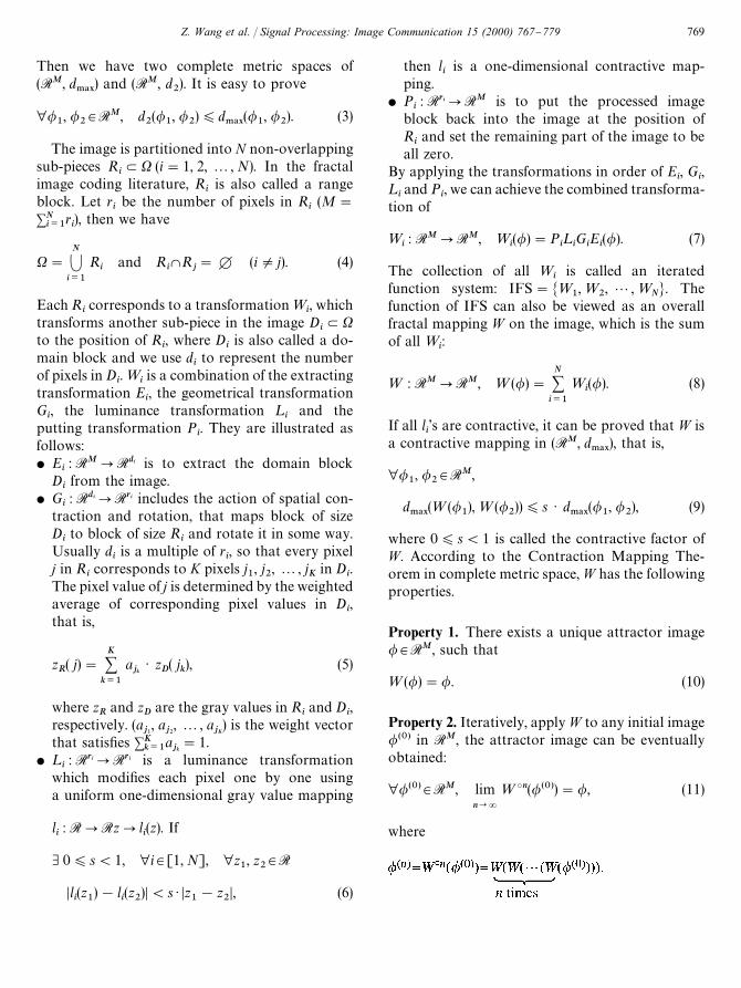
These three properties are the bases of fractalimage coding algorithms. If we have an image t tobe encoded, then the encoding is to "nd a fractalmapping W, which makes the error between=(t)and t as small as possible. When decoding, Wis applied iteratively to an arbitrary initial image/(0), then we obtain an image sequence /(0),/(1), 2, /(n), 2 and the attractor image / iseventually achieved, which is our reconstructed im-age. According to the collage theorem, the di!er-ence between / and t can be controlled by theerror between=(t) and t. In practice, even if someof the l
i's are non-contractive, the iteration proced-
ure can still converge to an attractor image. Al-though such kind of convergence is very di$cult tobe mathematically proved, the usage of non-con-tractive l
ihas been widely adopted by many fractal
image coding systems. More discussions are givenby Fisher in [2].
3. Partial fractal mapping
If only part of the image is coded using fractalmethod, then Eq. (4) should be modi"ed. First,we partition the whole image X into two partsX
1and X
2,
X"X1XX
2and X
1WX
2"H, (13)
where only X1part is modeled using fractal method
and X2
part is encoded using any other method.X
1can be further partitioned,
X1"
N1
Zi/1
Ri
and RiWR
j"H (iOj). (14)
Under such a partitioning, we have +N1i/1
ri(M.
Obviously, M!+N1i/1
riis the number of pixels in
X2.For the non-fractal coded part X
2, we use a con-
stant function mapping C : RMPRM, so that∀/3RM, we always have C(/)"h, where h is
a constant vector in RM and satis"es ∀j3X1,
h( j)"0.For the fractal coded part X
1, the process is
similar to that in Section 2.1 for basic fractal encod-ing. For each R
i, we "nd the appropriate=
iand D
i.
As to a certain Ri, its corresponding D
imay in
X1
or in X2, or part of it in X
1, and the remaining
part in X2.
We call the collection of =i
(i"1, 2 , N1)
a partial iterated function system: IFSP"
M=1,=
2, 2 ,=
N1N. The combination of IFSP and
the constant mapping C compose a partial fractalmapping,
=P : RMPRM,
=P(/)"C(/)#N1
+i/1
=i(/)"h#
N1
+i/1
=i(/). (15)
Now, we discuss the properties of =P.
Theorem 1. =P is a contractive mapping in(RM, d
.!9).
Proof. ∀/1, /
23RM ∀j3X
if j3RiLX
1, then
D(=P/1)( j)!(=P/
2)( j)D
"KviAK+k/1
ajk/1( j
k)B!v
iAK+k/1
ajk/2( j
k)BK
(6)( s ) K
K+k/1
ajk/1( j
k)!
K+k/1
ajk/
2( j
k)K
"s ) KK+k/1
ajk[/
1( j
k)!/
2( j
k)]K
)s )K+k/1
ajkD/
1( j
k)!/
2( j
k)D
)s )K+k/1
ajk) maxj/1,2,M
D/1( j)!/
2( j)D
"s ) maxj/1,2,M
D/1( j)!/
2( j)D"s ) d
.!9(/
1, /
2),
(16)
770 Z. Wang et al. / Signal Processing: Image Communication 15 (2000) 767}779

if j3X2, then
D(=P/1)( j)!(=P/
2)( j)D"Dh( j)!h( j)D
"0)s ) d.!9
(/1, /
2), (17)
therefore
maxj/1,2,M
D(=P/1)( j)!(=P/
2)( j)D)s ) d
.!9(/
1, /
2),
(18)
i.e.,
d.!9
(=P(/1),=P(/
2)))s ) d
.!9(/
1, /
2). h (19)
According to Theorem 1 and the ContractiveMapping Theorem in complete metric space, wecan prove that in (RM, d
.!9) space,=P satis"es the
three properties of W described in Section 2.1.In real applications, we are more concerned with
the d2
metric. However, in (RM, d2), it is di$cult to
prove the contractivity of either W or =P, but wehave the following theorems.
Theorem 2. There are a basic fractal mapping Wand a partial fractal mapping =P in (RM, d
2)
space, where the IFSP of =P is a subset of the IFSof W (i.e., the encoding of X
1part of =P is exactly
the same as the corresponding part of W). If W isa contractive mapping, then=P is also a contractivemapping.
Proof. ∀/1, /
23RM
Because W is contractive in (RM, d2), d
2(=(/
1),
=(/2)))s ) d
2(/
1, /
2). Thus, we have
d2(=P(/
1),=P(/
2))
"A1
M
M+j/1
D(=P/1)( j)!(=P/
2)( j)D2B
1@2
"A1
M+j|X1
D(=/1)( j)!(=/
2)( j)D2
#
1
M+j|X2
Dh( j)!h( j)D2B1@2
)A1
M
M+j/1
D(=/1)( j)!(=/
2)( j)D2B
1@2
"d2(=(/
1),=(/
2)))s ) d
2(/
1, /
2) h (20)
Theorem 2 demonstrates that=P is more likelyto be contractive than W in (RM, d
2) space.
Theorem 3. In (RM, d2) space, =P has a unique
attractor image /, such that =P(/)"/
Proof. (Existence.) From the properties of =P in(RM, d
.!9) space, we know that there exists a /3RM
that makes d.!9
(=P(/), /)"0, then we have
d2(=P(/), /)
(3)) d
.!9(=P(/), /)"0. (21)
Therefore in ( RM, d2) space,=P(/)"/.
That is to say,=P has the same attractor image/ in both ( RM, d
.!9) and (RM, d
2).
(Uniqueness.) If there exist two di!erent attrac-tors /
1, /
2of=P in (RM, d
2) space,
/1O/
2, =P(/
1)"/
1and =P(/
2)"/
2, (22)
then
[d2(=P(/
1), /
1)]2
"
1
M
M+j/1
D(=P/1)( j)!/
1( j)D2"0. (23)
Obviously, ∀j3X, D(=P/1)( j)!/
1( j)D"0
so, maxj/1,2,M
D(=P/1)( j)!/
1( j)D"0,
i.e., d.!9
(=P(/1), /
1)"0. (24)
Therefore /1
is an attractor of =P in (RM, d.!9
)space.
For the same reason, /2
is also an attractor in(RM, d
.!9) space.
But we have assumed /1O/
2. This is contradic-
tory to the theorem that the attractor of=P in (RM,d.!9
) space is unique. h
Theorem 4. If / is the attractor of =P in (RM, d2)
space, then
∀/(0)3RM, limn?=
(=P)3n(/(0))"/. (25)
Z. Wang et al. / Signal Processing: Image Communication 15 (2000) 767}779 771

Fig. 1. A general framework of the hybrid image encoding/decoding systems.
Proof. According to Property 2 of=P in (RM, d.!9
)space,
∀e'0, &N, ∀n'N, d.!9
((=P)3n(/(0)), /)(e (26)
so, d2((=P)3n(/(0)), /)
(3)) d
.!9((=P)3n(/(0)), /)(e,
(27)therefore
limn?=
(=P)3n(/(0))"/. h (28)
Theorems 3 and 4 prove that =P still satis"esProperties 1 and 2 in (RM, d
2) space. The di!erence
from those in (RM, d.!9
) space is that we cannotprove the collage theorem (Property 3). However,the error between the original image and the recon-structed image still can be controlled: ∀t3RM, if&e'0, such that d
.!9(=P(t), t))e, then we have
d2(/, t)
(3)) d
.!9(/, t))
e1!s
. (29)
4. A general framework for hybrid fractal-basedimage coding systems
According to the construction and propertiesof =P, we get a general hybrid fractal image
coding framework which is shown in Fig. 1.First, an image partitioning algorithm segment thewhole image into two parts X
1and X
2. X
2is en-
coded using some other techniques. Its decodingresult is the item of h in Eq. (15). The X
1part is
encoded using fractal method. The output codesinclude the fractal code of X
1(a), the code of
X2
part (b) and the segmentation information code(c). When decoding, the segmentation informationis "rst decoded, then we decode X
2and get h.
Finally, the fractal code is iteratively applied toreconstruct part X
1and we achieve our reconstruc-
ted image.The framework of Fig. 1 provides us with much#exibility for real implementation. The #exibilityexists in almost every section of the encodingside:1. The image partitioning algorithm.2. The encoding of the image partitioning informa-
tion. Obviously, this information must be en-coded using lossless methods.
3. The encoding of the non-fractal-coded regionX
2. Not just block-based methods can be used as
those in previous hybrid image coding systems.Actually, almost any image coding techniquescan be chosen.
772 Z. Wang et al. / Signal Processing: Image Communication 15 (2000) 767}779
4. The fractal image coding of X1, which includes
the selection of parameters, domain pool and thesearching procedure, etc.
5. Sometimes the decoding result of X2can be used
to predict some fractal parameters for the encod-ing of X
1, so that the coding e$ciency of X
1can
be improved. We show this in Fig. 1 using thedashed lines.
Apparently, many di!erent hybrid image codingschemes can be derived from the general frameworkshown in Fig. 1. Examples include those publishedin [4,6,7]. In the next section, we give anotherexample which shows more merits of our hybridmethod.
5. A hybrid image coding system
The image to be encoded is partitioned intonon-overlapping equal-sized blocks. Each blockis categorized into one of the following fourclasses:1. A large smooth region which is composed of at
least two of the connected adjacent blocks andcan be approximated su$ciently well by a uni-formly gray region.
2. A large smooth region which is composed of atleast two of the connected adjacent blocks andcan be su$ciently approximated by a plane (i.e.,linear approximation).
3. An isolatedly coded block simply approximatedby a uniformly gray block.
4. An isolatedly coded block modeled by fractal-based method.
Two bits are needed for each block to catalogue itinto one of the four classes. We use a losslessadaptive arithmetic coding algorithm presented in[12] to further compress this information.
5.1. Image partitioning
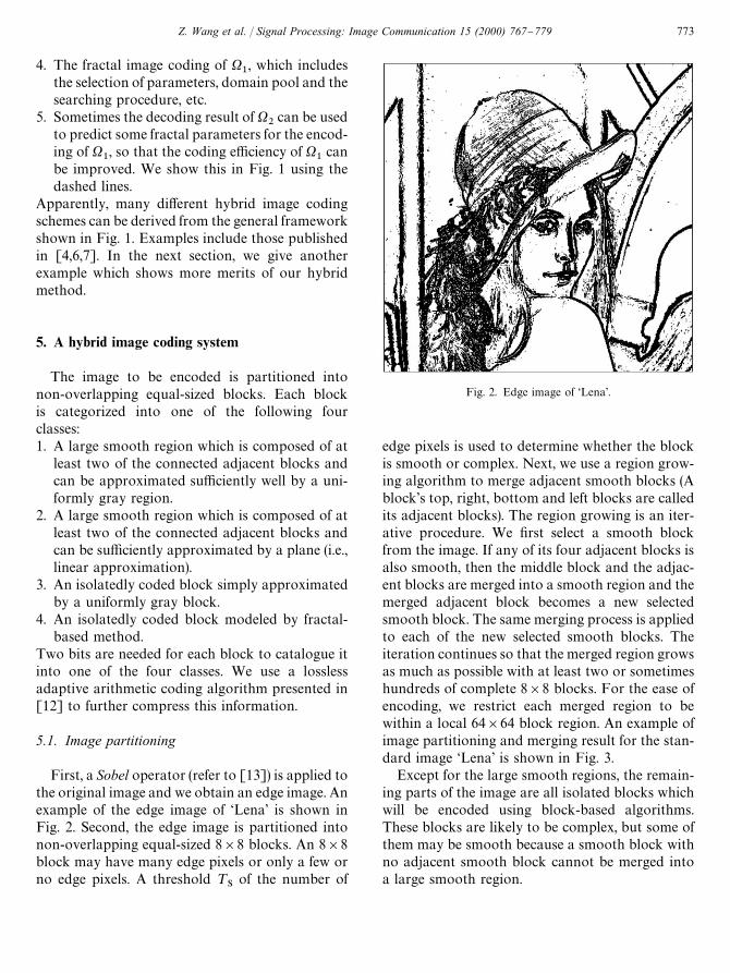
First, a Sobel operator (refer to [13]) is applied tothe original image and we obtain an edge image. Anexample of the edge image of &Lena' is shown inFig. 2. Second, the edge image is partitioned intonon-overlapping equal-sized 8]8 blocks. An 8]8block may have many edge pixels or only a few orno edge pixels. A threshold ¹
Sof the number of
Fig. 2. Edge image of &Lena'.
edge pixels is used to determine whether the blockis smooth or complex. Next, we use a region grow-ing algorithm to merge adjacent smooth blocks (Ablock's top, right, bottom and left blocks are calledits adjacent blocks). The region growing is an iter-ative procedure. We "rst select a smooth blockfrom the image. If any of its four adjacent blocks isalso smooth, then the middle block and the adjac-ent blocks are merged into a smooth region and themerged adjacent block becomes a new selectedsmooth block. The same merging process is appliedto each of the new selected smooth blocks. Theiteration continues so that the merged region growsas much as possible with at least two or sometimeshundreds of complete 8]8 blocks. For the ease ofencoding, we restrict each merged region to bewithin a local 64]64 block region. An example ofimage partitioning and merging result for the stan-dard image &Lena' is shown in Fig. 3.
Except for the large smooth regions, the remain-ing parts of the image are all isolated blocks whichwill be encoded using block-based algorithms.These blocks are likely to be complex, but some ofthem may be smooth because a smooth block withno adjacent smooth block cannot be merged intoa large smooth region.
Z. Wang et al. / Signal Processing: Image Communication 15 (2000) 767}779 773
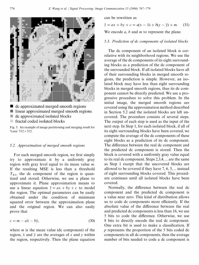
Fig. 3. An example of image partitioning and merging result for&Lena' 512]512.
5.2. Approximation of merged smooth regions
For each merged smooth region, we "rst simplytry to approximate it by a uniformly grayregion with gray level equal to its mean value m.If the resulting MSE is less than a threshold¹
E1, the dc component of the region is quan-
tized and stored. Otherwise, we use a plane toapproximate it. Plane approximation means touse a linear equation z("ax#by#c to modelthe region. The optimal parameters can be easilyobtained under the condition of minimumsquared error between the approximation planeand the original region. We can also easilyprove that
c"m!ax6 !by6 , (30)
where m is the mean value (dc component) of theregion, x6 and y6 are the averages of x and y withinthe region, respectively. Then the plane equation
can be rewritten as
z("ax#by#c"a(x!x6 )#b(y!y6 )#m. (31)
We encode a, b and m to represent the plane.
5.3. Prediction of dc components of isolated blocks
The dc component of an isolated block is cor-relative with its neighborhood regions. We use theaverage of the dc components of its eight surround-ing blocks as a prediction of the dc component ofthe surrounded block. If all isolated blocks have allof their surrounding blocks in merged smooth re-gions, the prediction is simple. However, an iso-lated block may have less than eight surroundingblocks in merged smooth regions, thus its dc com-ponent cannot be directly predicted. We use a pro-gressive procedure to solve this problem. In theinitial image, the merged smooth regions arecovered using the approximation method describedin Section 5.2 and the isolated blocks are left un-covered. The procedure consists of several steps.The output of each step is used as the input of thenext step. In Step 1, for each isolated block, if all ofits eight surrounding blocks have been covered, wecompute the average of the dc components of theseeight blocks as a prediction of its dc component.The di!erence between the real dc component andthe predicted dc component is stored. Then theblock is covered with a uniformly gray value equalto its real dc component. Steps 2,3,4, ... are the sameas Step 1 except that the uncovered blocks areallowed to be covered if they have 7, 6, 5, ... insteadof eight surrounding blocks covered. This proced-ure continues until all isolated blocks have beencovered.
Normally, the di!erence between the real dccomponent and the predicted dc component isa value near zero. This kind of distribution allowsus to code dc components more e$ciently. If theabsolute value of the di!erence between the realand predicted dc components is less than 16, we use5 bits to code the di!erence. Otherwise, we use8 bits to directly encode the real dc component.One extra bit is used to make a classi"cation. Ifp represents the proportion of the 5 bits coded dccomponents in all dc components, then the averagenumber of bits needed to code a dc component is
774 Z. Wang et al. / Signal Processing: Image Communication 15 (2000) 767}779

5p#8(1!p)#1"9!3p. Since the dc compo-nents are useful for the encoding of isolated blocksincluding fractal-coded blocks, this prediction pro-cedure can be viewed as a way where non-fractal-coded regions are used to help the encoding offractal-coded regions.
5.4. Encoding of isolated blocks
For each isolated block, we also "rst simply tryto approximate it by a uniformly gray block withgray level equal to its dc component. If the resultingMSE is less than a threshold ¹
E2, we do not need
any extra bit to code it because its dc componenthas been predicted and quantized using the methoddescribed in Section 5.3. Otherwise, we encode itusing a modi"ed fractal block coding (FBC)method called fractal block coding in residue do-main (FBCRD). A detailed description of FBCRDis presented in [11]. FBCRD is, in some ways,similar to a fractal image coding algorithm pro-posed by "ien and Leps+y [9]. Both of themcan get faster decoding than basic FBC andstore the scaling factor and the dc component in-stead of the scaling factor and the o!set forluminance transformations. This is bene"cialwith respect to encoding. FBCRD also has some-thing di!erent from "ien and Leps+y's algorithm.When decoding, the dc component of the domainblock is dynamically computed and is variable ineach iteration, while in "ien and Leps+y's algo-rithm, it is a "xed value. This di!erence freesFBCRD from several constraints on "ien andLeps+y's algorithm:1. There is no constraint on the image partitioning
method.2. It is not necessary for the domain block to be
made up of an integer number of complete rangeblocks.
3. More important for our usage, FBCRD canbe applied in a hybrid system where only partof the image is fractal-coded. In this kind ofsystems, since a domain block may coversome non-fractal coded regions, the dc com-ponent of the block can only be computeddynamically.In our hybrid system, all fractal-coded blocks are
complex blocks, thus more likely to be approxi-
mated by complex domain blocks. This allows us toexclude smooth domain blocks from the domainpool. If a domain block does not contain any pixelof any fractal-coded block, we regard it as a smoothdomain block and exclude it from the domain pool.The reduction of domain pool leads to two im-provements with respect to encoding. First, smallerdomain pool means less encoding time. Second,smaller domain pool allows us to use fewer bits toencode the position shift for the geometrical trans-formations.
5.5. Decoding and postprocessing
At the decoder, the block classi"cation informa-tion is the "rst to be decoded. Then large smoothregions are merged and covered using dc or linearapproximation method. A progressive procedurecorresponding to that in the encoder is applied todecode the dc components of isolated blocks andcover them with uniformly gray blocks. The resultof this progressive procedure is our initial image forfractal decoder iterations. Then FBCRD-based de-coding procedure is iteratively applied and moredetailed information in fractal coded blocks isgradually emerged through iterations. The iter-ation is terminated when we achieve a satisfactoryimage. In each fractal decoder iteration, non-frac-tal-coded regions are kept unchanged.
To reduce the discontinuities at the block andregion boundaries, we use a simple smooth algo-rithm similar to that introduced by Fisher in [2] tominimize these artifacts. That is, if the pixel valueson either side of a boundary are u and v, then theyare replaced by 3
4u#1
4v and 1
4u#3
4v, respectively.
This algorithm is applied only to boundary pixelsof large smooth regions and isolated blocks. Theinternal pixels of either large regions or isolatedblocks are kept unaltered.
6. Simulations and conclusions
We use some 8 bits/pixel gray scale images to testour hybrid system. Peak signal-to-noise ratio(PSNR) is used to make an objective evaluation. Inour hybrid system, each 8]8 block needs 2 bits tobe classi"ed into one of four classes. Usually, this
Z. Wang et al. / Signal Processing: Image Communication 15 (2000) 767}779 775

classi"cation information can be compressed by25}40% by using adaptive arithmetic coding algo-rithm [12]. We use 8 bits to code the dc componentfor a dc approximated large smooth region and8 bits to code each of the 3 parameters for a linearapproximated merged smooth region. For isolatedblocks, the proportion p is typically around 0.65, so9!3p+7 is the average number of bits for a dccomponent. For a fractal-coded block, we use 6 bitsto code scaling factor and 3 bits to code symmetry.Since the domain pool is condensed, the bits neededfor the position of domain block is reduced from 10to 9 bits. Averagely, a total of about 25 bits areneeded for each fractal-coded block including thebits for its dc component.
The selection of the three threshold parameters¹
S, ¹
E1and ¹
E2can be used to control the tradeo!
between high compression ratio and good imagequality. If ¹
Sis higher, more blocks will be
regarded as smooth, thus we will obtain highercompression ratio but lose more image details. Sim-ilarly, if ¹
E1and ¹
E2are higher, more blocks or
regions will be simply represented using a uniform-ly gray region and the compression will be higher,but approximation becomes less e$cient. Fig. 4shows PSNR versus compression ratios and com-pares our hybrid system with Fisher's quadtreefractal block coding method [2] and the JPEG stillimage coding standard [10]. It appears that ourhybrid system performs better than the fully frac-tal-coded quadtree method in a wide range of com-pression ratios. JPEG is better at low compressionratios, but the hybrid system outperforms JPEG athigh compression ratios larger than 30. Figs. 5 and6 show the decoded images of &Lena' and &Peppers'by our hybrid system, the quadtree method and theJPEG standard at similar compression ratios. Inthe hybrid system, the threshold parameters are setto ¹
S"0, ¹
E1"32 and ¹
E2"64, respectively. In
Fig. 7, some enlarged areas of the decoded imagesby the hybrid system and the quadtree method areprovided, where the areas are extracted from Fig. 5.Our hybrid system appears to show major im-provements with respect to the subjective quality ofthe reconstructed images.
Another bene"t from our hybrid system is thesave of encoding and decoding computation time.The reason is manifold. First, the number of fractal
Fig. 4. A comparison of compression results for image &Lena'512]512.
coded blocks is reduced compared with fully fractalblock coding algorithm, while the encoding ofother regions is much faster. Second, the domainpool for fractal block coding is reduced. Since mostof the encoding time of fractal image compressionsystems is used in searching for suitable domainblocks in the domain pool, smaller domain poolmeans less encoding time. Third, smaller domainpool allows us to use fewer bits to code the positionshift for the geometrical transformations. Experi-mentally, only 20}60% the encoding time of thefully fractal block coding algorithm is needed.Finally, the number of decoder iterations is lessthan the fully fractal coding algorithm due to thegood convergence property of FBCRD.
In this paper, we propose the concept of partialfractal mapping and introduce a general frameworkfor a class of fractal-based hybrid image codingsystems. In addition, a real hybrid system is pre-sented where non-fractal-coded regions are used tohelp the encoding of fractal-coded regions. Experi-ments show that our hybrid system outperformsthe JPEG image compression standard at highcompression ratios. We believe that under our gen-eral framework, the compression result can be fur-ther improved by combining fractal technique withother more sophisticated methods.
776 Z. Wang et al. / Signal Processing: Image Communication 15 (2000) 767}779
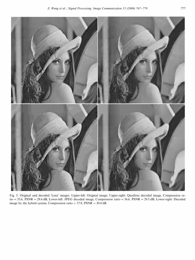
Fig. 5. Original and decoded &Lena' images. Upper-left: Original image; Upper-right: Quadtree decoded image, Compression ra-tio"35.6, PSNR"28.6 dB; Lower-left: JPEG decoded image, Compression ratio"36.6, PSNR"29.5 dB; Lower-right: Decodedimage by the hybrid system, Compression ratio"37.9, PSNR"30.4 dB.
Z. Wang et al. / Signal Processing: Image Communication 15 (2000) 767}779 777

Fig. 6. Original and decoded &Peppers' images. Upper-left: Original image; Upper-right: Quadtree decoded image, Compressionratio"34.3, PSNR"28.7 dB; Lower-left: JPEG decoded image, Compression ratio"34.0, PSNR"29.7 dB; Lower-right: Decodedimage by the hybrid system, Compression ratio"35.0, PSNR"30.5 dB.
778 Z. Wang et al. / Signal Processing: Image Communication 15 (2000) 767}779
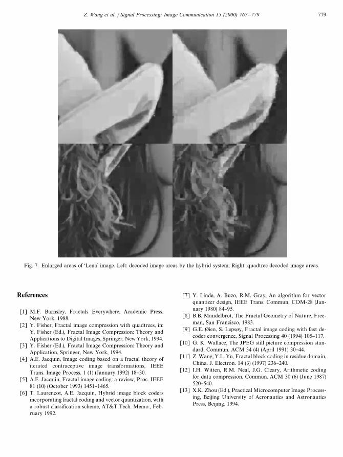
Fig. 7. Enlarged areas of &Lena' image. Left: decoded image areas by the hybrid system; Right: quadtree decoded image areas.
References
[1] M.F. Barnsley, Fractals Everywhere, Academic Press,New York, 1988.
[2] Y. Fisher, Fractal image compression with quadtrees, in:Y. Fisher (Ed.), Fractal Image Compression: Theory andApplications to Digital Images, Springer, New York, 1994.
[3] Y. Fisher (Ed.), Fractal Image Compression: Theory andApplication, Springer, New York, 1994.
[4] A.E. Jacquin, Image coding based on a fractal theory ofiterated contraceptive image transformations, IEEETrans. Image Process. 1 (1) (January 1992) 18}30.
[5] A.E. Jacquin, Fractal image coding: a review, Proc. IEEE81 (10) (October 1993) 1451}1465.
[6] T. Laurencot, A.E. Jacquin, Hybrid image block codersincorporating fractal coding and vector quantization, witha robust classi"cation scheme, AT&T Tech. Memo., Feb-ruary 1992.
[7] Y. Linde, A. Buzo, R.M. Gray, An algorithm for vectorquantizer design, IEEE Trans. Commun. COM-28 (Jan-uary 1980) 84}95.
[8] B.B. Mandelbrot, The Fractal Geometry of Nature, Free-man, San Francisco, 1983.
[9] G.E. "ien, S. Leps+y, Fractal image coding with fast de-coder convergence, Signal Processing 40 (1994) 105}117.
[10] G. K. Wallace, The JPEG still picture compression stan-dard, Commun. ACM 34 (4) (April 1991) 30}44.
[11] Z. Wang, Y.L. Yu, Fractal block coding in residue domain,China. J. Electron. 14 (3) (1997) 236}240.
[12] I.H. Witten, R.M. Neal, J.G. Cleary, Arithmetic codingfor data compression, Commun. ACM 30 (6) (June 1987)520}540.
[13] X.K. Zhou (Ed.), Practical Microcomputer Image Process-ing, Beijing University of Aeronautics and AstronauticsPress, Beijing, 1994.
Z. Wang et al. / Signal Processing: Image Communication 15 (2000) 767}779 779