hybrid wall construction and quality control issues … wall construction and quality control issues...
TRANSCRIPT

Hybrid Wall Construction and Quality Control Issues in Wyandotte, Michigan
A. Lukachko, A. Grin, and D. Bergey Building Science Corporation
December 2013

NOTICE
This report was prepared as an account of work sponsored by an agency of the United States government. Neither the United States government nor any agency thereof, nor any of their employees, subcontractors, or affiliated partners makes any warranty, express or implied, or assumes any legal liability or responsibility for the accuracy, completeness, or usefulness of any information, apparatus, product, or process disclosed, or represents that its use would not infringe privately owned rights. Reference herein to any specific commercial product, process, or service by trade name, trademark, manufacturer, or otherwise does not necessarily constitute or imply its endorsement, recommendation, or favoring by the United States government or any agency thereof. The views and opinions of authors expressed herein do not necessarily state or reflect those of the United States government or any agency thereof.
Available electronically at http://www.osti.gov/bridge
Available for a processing fee to U.S. Department of Energy and its contractors, in paper, from:
U.S. Department of Energy Office of Scientific and Technical Information
P.O. Box 62 Oak Ridge, TN 37831-0062
phone: 865.576.8401 fax: 865.576.5728
email: mailto:[email protected]
Available for sale to the public, in paper, from: U.S. Department of Commerce
National Technical Information Service 5285 Port Royal Road Springfield, VA 22161 phone: 800.553.6847
fax: 703.605.6900 email: [email protected]
online ordering: http://www.ntis.gov/ordering.htm
Printed on paper containing at least 50% wastepaper, including 20% postconsumer waste

iii
Hybrid Wall Construction and Quality Control Issues in Wyandotte, Michigan
Prepared for:
The National Renewable Energy Laboratory
On behalf of the U.S. Department of Energy’s Building America Program
Office of Energy Efficiency and Renewable Energy
15013 Denver West Parkway
Golden, CO 80401
NREL Contract No. DE-AC36-08GO28308
Prepared by:
A. Lukachko, A. Grin, and D. Bergey
Building Science Corporation
30 Forest Street
Somerville, MA 02143
NREL Technical Monitor: Cheryn Metzger
Prepared under Subcontract No. KNDJ-1-40337-03
December 2013

iv
[This page left blank]

v
Contents List of Figures ............................................................................................................................................ vi List of Tables .............................................................................................................................................. vi Definitions .................................................................................................................................................. vii Executive Summary ................................................................................................................................. viii 1 Introduction ........................................................................................................................................... 1
1.1 The Purpose of This Research Project .................................................................................1 1.2 Previous Building America Research Work With the Michigan NSP2 Program ................2 1.3 Michigan Neighborhood Stabilization Program 2 Energy Efficiency Technology Package2 1.4 Research Questions ..............................................................................................................4
2 Research and Development of Hybrid Insulation High R-Value Enclosures ................................. 5 2.1 High R-Value Enclosures ....................................................................................................5 2.2 Hybrid Insulation Assemblies ..............................................................................................7
2.2.1 Hybrid Insulation Wall and Roof Assemblies for Wyandotte .................................8 2.2.2 Cost Comparison to Other High R-Value Assemblies ..........................................10
2.3 Quality Assurance for Whole-House Airtightness ............................................................12 3 Evaluating Hybrid Insulation High R-Value Enclosures in Wyandotte ........................................ 14
3.1 Design and Construction Process Results ..........................................................................14 3.1.1 Airtightness Test Too Late; Moved to Earlier Stage .............................................14 3.1.2 Inaccessible Framing Cavities Found; Resolved in Drawings ..............................16 3.1.3 Spray Polyurethane Foam Installation Problems Found; Resolved Through
Specifications and Quality Control ........................................................................18 3.2 Whole-House Airtightness Measurement Results .............................................................19
4 Conclusions and Recommendations ............................................................................................... 21 4.1 Evaluation of the Process Changes and Results ................................................................21 4.2 Recommended Practices for Design ..................................................................................23 4.3 Recommended Practices for Preconstruction and Construction ........................................24 4.4 Recommended Practices for Quality Control ....................................................................25 4.5 Implications for Winter Construction Costs ......................................................................26 4.6 Future Considerations ........................................................................................................28
References ................................................................................................................................................. 29 Appendix: BEopt Energy Analysis .......................................................................................................... 31
vi
List of Figures Figure 1. Common approaches to high R-value enclosures .................................................................. 6 Figure 2. Wyandotte typical wall section—hybrid insulation approach ................................................ 8 Figure 3. NIST NZERTF airtightness test results ................................................................................... 13 Figure 4. Air leakage paths identified during blower door test marked for remedial action ............ 16 Figure 5. Missing ccSPF insulation at the bottom of rim joist ............................................................. 17 Figure 6. Underside of ccSPF sprayed to interior side of roof sheathing; fiberglass cavity fill
insulation removed; condensation visible ....................................................................................... 18 Figure 7. Wyandotte estimated source energy by end use .................................................................. 32 Figure 8. Savings versus benchmark, annualized cost ........................................................................ 32
Unless otherwise noted, all figures were created by Building Science Corporation.
List of Tables Table 1. Summary of Michigan NSP2 Energy Efficiency Package Components.................................. 3 Table 2. Current Recommended "True" Minimum R-Value (±)1 Including Thermal Bridging
(Straube 2010) ....................................................................................................................................... 5 Table 3. Selection Guide for Hybrid Insulation High R-Value Walls* ................................................... 10 Table 4. Summary of Incremental Costs for Various High R-Value Enclosure Technologies for
Typical Wyandotte NSP2 House ....................................................................................................... 11 Table 5. Ferndale, Michigan Air Infiltration Test Results ...................................................................... 12 Table 6. 2011 Airtightness Test Results From Wyandotte NSP2 New Construction ......................... 19 Table 7. 2012 Airtightness Test Results From Wyandotte NSP2 New Construction ......................... 19 Table 8. Preconstruction Checklist for SPF Air Barrier Details ........................................................... 24 Table 9. BEopt Inputs for Wyandotte Builder Standard Practice, BSC Recommendations, and As-
Built Specification .............................................................................................................................. 31
Unless otherwise noted, all tables were created by Building Science Corporation.

vii
Definitions
ACH Air changes per hour
BA Building America
BSC Building Science Corporation
ccSPF Closed-cell spray polyurethane foam
CFM Cubic feet per minute
EF Energy factor
EPS Expanded polystyrene
GSHP Ground source heat pump
HUD U.S Department of Housing and Urban Development
MSHDA Michigan State Housing and Development Authority
NIST National Institute of Standards and Technology
NSP2 Neighborhood Stabilization Program 2
NZERTF Net Zero Energy Residential Test Facility
ocSPF opened-cell spray polyurethane foam
OSB Oriented strand board
PIC Polyisocyanurate
SEER Seasonal energy efficiency ratio
SHGC Solar heat gain coefficient
XPS Extruded polystyrene
viii
Executive Summary
The Wyandotte NSP2 research project is part of a series of Building America research projects that have examined enclosure and mechanical systems for pre-production homes (single prototypes and pilot projects at production scale) intended for construction in cold climate markets. This report is the second report on the Wyandotte NSP2 project in Wyandotte, Michigan and documents refinements to the design, construction, and quality control for the high R-value enclosure. The report will be of interest to designers and builders of production housing in cold climates.
The focus of the second round of research was on using the hybrid insulation approach (using 2-in. insulating sheathing with 2-in. closed-cell spray polyurethane foam [ccSPF] applied to the interior side in the framing cavity and the remainder of the cavity filled with batt insulation) to develop a reliable method of achieving consistently low airtightness numbers. To do this, Building Science Corporation (BSC) worked with the project team to make a series of changes to the architectural plans, the construction schedule, and the quality control activities during construction. The cost of this approach compared to other methods of constructing high R-value wall and roof assemblies is considered.
There are two primary outcomes from this research. First, the airtightness measurements demonstrate that with a shallow learning curve, even new builders entering the program having little experience with the technology package are able to achieve consistent results that are < 1.5 ACH50. Second, the process changes implemented to help secure these results were straightforward and ended up encouraging better communication between designer, builder, and the City officials supervising the project.
As construction at Wyandotte moves toward completion, BSC will continue to collect data on test results and construction issues. However, with the recommendations for design, construction, and quality control, BSC considers the hybrid insulation approach employed for the Wyandotte project to be ready for deployment in a production setting.

1
1 Introduction
The Michigan Neighborhood Stabilization Program 2 (NSP2) project is located in Wyandotte, Michigan, a community of approximately 26,000 people located southwest of Detroit. The City of Wyandotte is one of 12 Michigan municipalities included in the Michigan NSP2 Consortium. These municipalities are Detroit, Highland Park, Hamtramck, Wyandotte, Flint, Saginaw, Pontiac, Lansing, Battle Creek, Kalamazoo, Grand Rapids, and Benton Harbor. The Consortium has received approximately $224 million in funding from U.S. Department of Housing and Urban Development (HUD) for redevelopment of blighted and vacant land within the participating communities. In total, Michigan NSP2 project is the largest award from HUD under this program of the Michigan State Housing and Development Authority (MSHDA).
At Wyandotte, the project team includes the City of Wyandotte, an architect working directly for the City, Building Science Corporation (BSC), BSC’s industry partners, and five local homebuilders. The City and the architect, with the support of BSC, have developed new house plans for up to 30 houses to be built in the central neighborhoods of Wyandotte.
This research report describes the results of work completed in 2012 that was focused on the design and construction of high R-value assemblies using a hybrid approach to insulation and airtightness.
1.1 The Purpose of This Research Project The Wyandotte NSP2 research project is part of a series of Building America (BA) research projects that have examined enclosure and mechanical systems for preproduction homes (single prototypes and pilot projects at production scale) intended for construction in cold climate markets. With this work, the primary strategic objectives for BSC are:
1. To develop affordable high performance enclosure assemblies.
2. To develop complete high performance technology packages for affordable homes.
The pilot community in Wyandotte, Michigan employs an energy-efficient technology package that has been designed for HUD NSP2 projects in a cold climate. Results from previous projects in this community are described below in Section 1.3. Using the insulating sheathing with spray foam hybrid insulation approach to develop a reliable method of achieving consistently low airtightness numbers was identified in an earlier phase of this research as a priority for further development. In 2012, BSC research addressed the following tactical objectives:
• Understand and document the effectiveness of new quality control procedures designed to work with hybrid enclosure assemblies.
• Discover and document cost and implementation issues with hybrid high R-value assemblies.
• Review and report on measured energy use for affordable high performance homes.

2
1.2 Previous Building America Research Work With the Michigan NSP2 Program BSC was involved in the Wyandotte NSP2 project at two stages prior to 2012. In 2010, BSC studied the feasibility of building a high performance enclosure as part of the planned new construction specifications. Work at this stage included BEopt analysis of potential energy efficiency measures and a review of the proposed construction details, focusing on water management details and thermal control issues (thermal bridging, insulation quantities, and insulation materials). At this stage, the City of Wyandotte had set plans for a future district ground source heat pump (GSHP) system that would involve both the new and existing houses in the NSP2 program. The objective of the GSHP system is to greatly reduce the heating and cooling costs of houses in the NSP2 district—and this is dependent on a significant reduction in heating and cooling loads through the enclosure. The GSHP planning, system design, and installation were contracted separately from the house design and construction and were already at an advanced stage. BSC also assisted the City and the project architect in the task of reducing the total cost of the proposed construction specification, while maintaining a high level of whole-house energy efficiency. The completed house designs were bid for a 2011 construction start. The houses have been divided into “bid packs” of five to eight houses with each bid pack being constructed by a different builder. A summary of this work was published in 2010 as a reference for other cold climate projects working within the NSP2 funding requirements for affordability and energy performance (Lukachko and Bergey 2010).
In 2011, BSC was involved in the construction of the first 10 new houses in the program in several capacities:
1. Preconstruction coordination and training
2. Field review of construction in progress
3. Support for in-progress changes to drawings, specifications, and onsite workflow
4. Performance testing of completed houses
5. Support for development of operation and maintenance information for homeowners.
The results of this research work were published at the end of 2011 (Lukachko and Grin 2011). Data on GSHP performance were not available at this time. The 2011 report addressed the construction issues (see Section 1.4) with the hybrid insulation approach to high R-value walls and the results of airtightness measurements. In general, the project showed that respectable whole house airtightness measurements could be achieved by relatively inexperienced homebuilders, but underlined the importance of preconstruction planning and attention to water management and airtightness details at the drawing stage.
1.3 Michigan Neighborhood Stabilization Program 2 Energy Efficiency Technology Package
The energy efficiency technology package used for the Wyandotte NSP2 houses in 2012 was similar to the specification that was developed in previous years (see Table 1 below). The houses in the NSP2 program varied by size and style, but with only minor variations, the technology specification was consistent for each house.

3
Table 1. Summary of Michigan NSP2 Energy Efficiency Package Components
ENCLOSURE SPECIFICATIONS
Roof Description Dark color asphalt shingles on rafter roof—unvented cathedralized attic
Roof Insulation 5 in. (R-30) ccSPF on underside of roof, R-19 fiberglass batt below
Walls Description Advanced framed 2 × 6 wall structure with hybrid insulation approach using insulating sheathing and spray foam with fiberglass batt in the wall cavity
Walls Insulation 2 in. (R-10) XPS sheathing, 2 in. depth (R-12) ccSPF to interior of sheathing inside framing cavity, 3½ in.
(R-12) fiberglass to fill balance of cavity Foundation Description Conditioned basement/crawlspace
Foundation Insulation 2 in. PIC (R-13) on interior of foundation walls or 2 in. (R-12) ccSPF; 2 I n. XPS (R-10) subslab
Windows Description Double-pane vinyl-framed with LoE3 spectrally selective glazing
Windows Manufacturer Anderson Windows U-value U = 0.28 Windows SHGC SHGC = 0.29
Infiltration Specification 2.5 in.2 leakage area/100 ft2 enclosure @ 50 Pa MECHANICAL SYSTEMS SPECIFICATIONS
Heating Description 9.2 HSPF GSHP Heating Manufacturer and Model WaterFurnace
Cooling Description 18 SEER GSHP Cooling Manufacturer and Model WaterFurnace
Domestic Hot Water Description Tank electric water heater with desuperheater (EF = 0.98)
Domestic Hot Water Manufacturer and Model Rheem
Conditioned Air Distribution Description
R-6 flex ducts in conditioned unvented cathedralized attic
Conditioned Air Distribution Leakage Maximum 5% duct leakage to outside
Ventilation Description
Supply-only system with Aprilaire 8126 VCS, 33%, meets ASHRAE 62.2
Duty Cycle: 10 min on; 20 min off, 50 CFM average flow
Ventilation Manufacturer and Model Aprilaire 8126 VCS fan cycler
Return Pathways Description Central return on first floor, jump ducts in bedrooms

4
From the outset, Wyandotte had the goal of constructing affordable, durable, energy-efficient houses that would become long-term assets to their owners and to the community. There are a couple of important considerations that influenced the technology included in the package.
The first consideration was that a portion of all completed houses were to be sold to low-income families. The City wanted to ensure that the cost to operate and maintain these houses would be much lower than the costs that the homeowners would expect in typical housing.
The second consideration had to do with the fit with a planned district GSHP system. Before the housing construction program started, it was decided that Wyandotte Municipal Services—the provider of electricity through a City-owned plant—would develop a series of wells in the NSP2 neighborhoods that could be used to supply heating and cooling to the new houses in the program. As more of the wells were installed, the Wyandotte Municipal Services would begin to offer contracts to neighboring houses to make use of the extra capacity of each well—it was assumed that two houses could be serviced by a single 500-ft deep well. Later, the wells would be linked together to pool extra capacity and service an even greater number of houses. Therefore, the load of each house is of great interest: if the heating and cooling loads of new houses could be greatly reduced, the City would be able to service a greater number of houses on the future system.
1.4 Research Questions Following the research work in Wyandotte in 2011, BSC proposed the following research questions to address issues uncovered during construction and further development of the hybrid insulation approach to high R-value enclosures:
1. Can whole-house airtightness results be improved with a modification to the typical inspection protocol to have an airtightness test immediately following installation of the ccSPF insulation in the proposed hybrid enclosure assemblies?
2. Can the NSP2 technology package be successfully deployed for smaller house designs as part of a community development strategy?
3. Do refinements to the framing plan allow builders to more reliably reach whole-house airtightness targets using the hybrid enclosure assemblies?
4. How does this method of achieving High R-value walls compare to other methods on cost and constructability?
Research question No. 2 was posed at the outset of the project when the team was exploring the applicability of this technology package to another Michigan NSP2 community in Hamtramck. The properties in the Hamtramck NSP2 zone are much narrower and would require smaller house designs. The proximity to the property line for these houses would raise a series of issues, including the combustibility of cladding and wall assembly components, and the impact of the total wall thickness on interior space planning across the narrow width of the houses. An understanding of these issues was sought to increase the applicability of the proposed technology package to a greater range of cold climate houses. Hamtramck was not included in the 2012 research project and so research question No. 2 was not answered.

5
2 Research and Development of Hybrid Insulation High R-Value Enclosures
The following section describes the past and current BA work that contributed to the current research project. Past BA research work involving High R-value enclosures, hybrid insulation assemblies, and quality assurance for whole-building airtightness is discussed below.
2.1 High R-Value Enclosures The development of high thermal resistance or “high R-value” building enclosures is a major area of long-term research in the Building America program. A selection of the program’s work in this area that directly inform this research project is briefly reviewed here.
In 2012, BSC was tasked with preparing a white paper on high thermal resistant enclosures (Straube 2010). This paper defined performance requirements, reviewed past and current research, and outlined the research gaps in this area, including the need to demonstrate and document methods to achieve high levels of airtightness. Minimum thermal resistance for high R-value walls was proposed (see Table 2 below).
Table 2. Current Recommended "True" Minimum R-Value (±)1 Including Thermal Bridging (Straube 2010)
Climate Zone Wall Vented
Attic Compact
Roof Basement
Wall Exposed
Floor Slab
Edge2 Windows
(U/SHGC)3 Sub-slab4
1 10 40 35 5 10 none yes none 2 15 50 40 10 20 5 0.35/<0.25 none 3 20 50 45 10 20 7.5 0.30/<0.3 5 4 25 60 45 15 30 7.5 0.30/<0.35 7.5 5 30 65 50 15 30 10 0.24/<0.50 7.5 6 35 75 60 20 40 10 0.18/-- 10 7 40 90 65 25 45 15 0.15/-- 15 8 50 100 75 35 50 20 0.15/-- 20
1. These are recommended values based on experience—see Economics section 2. Slab edge insulation includes all of stem wall or monolithic slab edge 3. Solar heat gain coefficient 4. Full area coverage of slabs
In 2009 and 2010, BSC conducted a series of studies, each focusing on a different part of the building enclosure. These included reports for high R-value walls, foundations, and roofs (Straube and Smegal 2009). These reports looked at thermal control, but also moisture control, durability, buildability, cost, and material use, for common high R-value assembly designs.
A study conducted by IBACOS in 2010 (Broniek et al. 2010) also evaluated different approaches to the construction of high R-value wall assemblies. This study included a comparison of simulation results using a whole-house energy model and collected experience with construction issues through consultation with builders and manufacturers, and through the construction of full-scale mockups. In addition to the performance criteria examined in the BSC study above,
6
IBACOS looked at architectural flexibility (i.e., the ability of the wall system to accommodate a wide range of floor plans and finishes) and scalability to mass production in multiple climate zones.
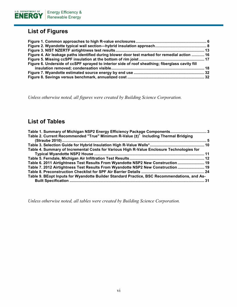
From the analysis work described above, a broad classification of the approaches to high R-value enclosures for cold climate residential buildings can be suggested (see Figure 1 below).
Exterior Approach
Inside Approach
All Exterior
Hybrid Insulation
Insulating Sheathing With
Cavity Fill
2 × 8+
Double Stud or Truss
SIPS
Figure 1. Common approaches to high R-value enclosures Notes: 1. For the diagrams above, the left-hand side is the “outside climate” and the right-hand side is the “inside climate.”
2. Dark gray is rigid insulation, medium gray is spray foam insulation, light gray is cavity fill insulation, and white is open structure.
There are two common approaches: adding insulation to the exterior of the building structure (i.e., the “exterior” approach), which may include insulation materials inside the structural cavity or none at all; and adding more insulation inside the structural cavity (i.e., the “inside” approach), which uses different types of insulation material and an increased depth of the cavity to reach the higher R-value levels. Within both of the general approaches, there are multiple methods that employ different insulation products. Each method has different strengths and weaknesses. Walls are illustrated in Figure 1, but the classification can apply to roofs with a few modifications.
Field research projects have been conducted by BA teams to assess different approaches to high R-value enclosures in number of climate zones. Some recent cold climate examples include the

7
BSC Westford Habitat for Humanity project (exterior approach) and the BSC research with Transformations, Inc. (inside approach)—both located in Massachusetts.
The Westford Habitat project used a 4-in. layer of PIC insulating sheathing (R-26) outside of advanced framed 2 × 6 walls and 4 in. over engineered wood rafters. With the cellulose cavity fill insulation included (R-19), this prototype house has R-45 walls, R-66 roof insulation, R-26 basement wall insulation, R-10 under the basement floor slab, and a whole house airtightness of 1.5 ACH50. Important lessons were learned about this thick insulating sheathing approach in the construction phase, including cladding attachment strategies and special details for window and door installation (Lstiburek 2009; BSC 2010a).
The Transformations, Inc. project involves three communities of houses that employ a 12-in. thick double-stud wall assembly to achieve a high R-value enclosure. The double-stud approach is favored by builders on a material cost basis because it allows for the use of low-cost cavity fill insulation materials. Double-stud walls, however, are at a higher risk of moisture-related problems than an insulating sheathing approach because of the colder wintertime temperature of the exterior sheathing. The moisture risks associated with this approach have been documented as part of the high R-value wall study (Straube and Smegal 2010) and the Transformations project continues to assess this issue with long-term field measurement of a side-by-side comparison between full-cavity open-cell spray polyurethane foam (ocSPF) and full-cavity netted and dry blown-in cellulose (BSC 2010b, Ueno et al. 2012).
2.2 Hybrid Insulation Assemblies The Westford Habitat for Humanity project looked at an exterior approach to high R-value walls and roofs with insulation levels that are much higher than what most production home builders would likely build. The Transformations, Inc. project involved several communities of houses that were built in a higher volume production setting. The double stud approach, however, involves significant changes to the framing process that may not find traction in all production environments. Recent research work has also looked at hybrid insulation assemblies to find an approach that may become an evolution of typical framing practices.
In the past, research work has been completed on “flash and fill” (also known as “flash and batt” and “flash and blow”) technologies. The approach uses two types of insulation for different purposes. The assembly may use plywood, oriented strand board (OSB), or insulating sheathing. The first type of insulation—the “flash”—is ccSPF sprayed either as a minimal (0.5–1.0 in.) layer inside of the sheathing or in a “picture frame” pattern around the perimeter of each stud bay. The second type of insulation then fills the cavity. This insulation material could be either fiberglass or rock wood batt insulation—the “batt”—or blown cellulose or fiberglass insulation—the “blow.” The objective is to use a minimal amount of the higher priced SPF insulation to secure a higher level of airtightness for the wall and then have the less expensive but lower R-value per inch insulation complete the assembly. This technology is primarily suited for achieving improved airtightness at low cost, but is the basis for the hybrid insulation approach that also achieves higher overall thermal resistance.
A recent BSC research project (Grin and Lstiburek 2012) looked at the moisture and structural performance of hybrid insulation strategies for walls at the subsystem or assembly level. Wall assemblies in this study included variations on insulating sheathing, ccSPF in the wall cavity
8
sprayed to the interior side of the exterior sheathing, and then a cavity fill insulation in the balance of the cavity. The report used energy (BEopt), thermal (THERM 5), hygrothermal (WUFI 4) simulations, and structural analysis (ASTM E72) to evaluate different assembly options. The assembly with the lowest associated incremental cost, the lowest air leakage condensation risk (< 1% of the year in Minneapolis), the best structural performance, and the second-best annual energy savings at 34% in Minneapolis and 29% in New Orleans consisted of the following, starting from the outermost material:
• Exterior vertical wood furring for cladding attachment
• 1.5-in. foil-faced PIC board insulation
• Diagonal metal strapping
• 2 × 6 advanced framed wall
• 1.5-in. ccSPF, full depth in each stud bay
• 4-in. loose-fill cellulose insulation
• 0.5-in. gypsum with latex paint finish.
This wall assembly was the basis for the Wyandotte NSP2 enclosure design.
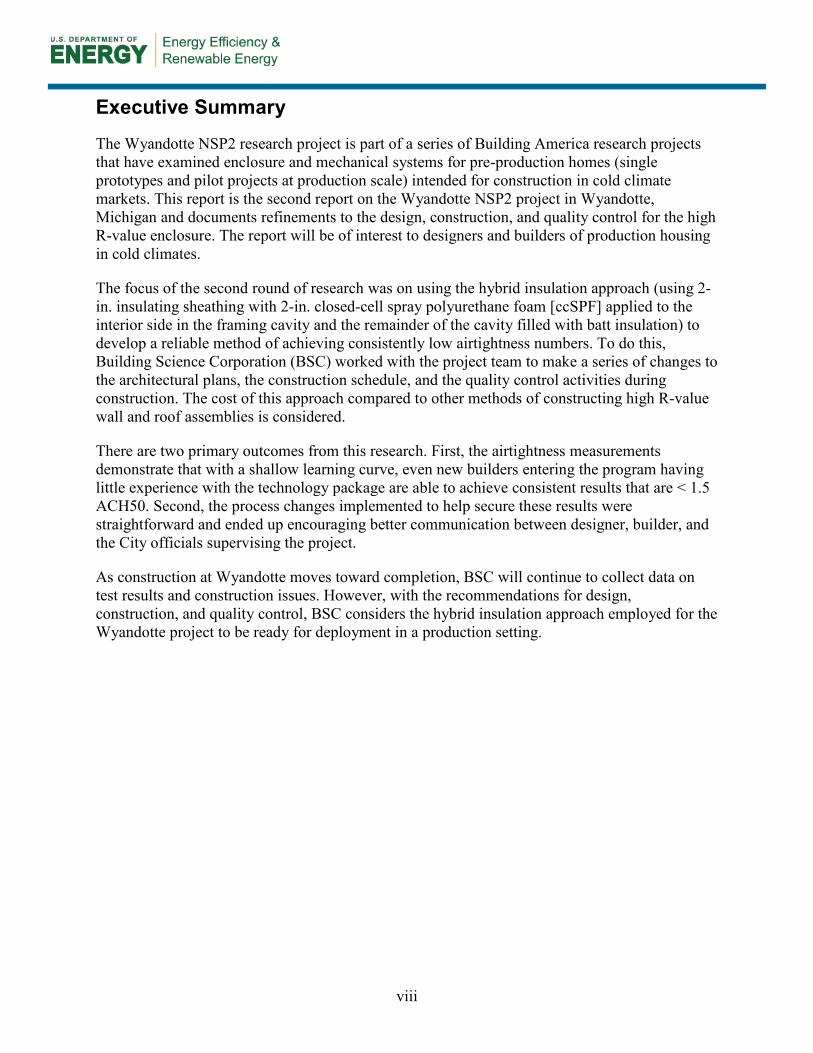
2.2.1 Hybrid Insulation Wall and Roof Assemblies for Wyandotte The hybrid insulation system used for the Wyandotte wall and roof assemblies is more complex than conventional insulation systems (see Figure 2 below). Three insulation materials are used to develop the R-34 and R-50 nominal thermal resistance for the wall and roof assemblies, respectively. However, there are several advantages that this hybrid approach offers for site-built housing with high performance expectations for thermal resistance, condensation control, and airtightness.
Figure 2. Wyandotte typical wall section—hybrid insulation approach
1. Insulating Sheathing
2. ccSPF Insulation
3. Cavity Fill Insulation

9
First, insulating sheathing (#1 in Figure 2) is used to provide a continuous thermal enclosure over the structural frame. In this construction, OSB shear panels are used at the corners of the house. The insulating sheathing also is detailed to perform as a drainage plane. In an ideal situation all of the thermal insulation would be located to the outside of the structural frame (Lstiburek 2009). In sufficient thickness, this eliminates the effect of the most common thermal bridges and provides control of condensation on the interior side of the exterior sheathing (Straube 2011). However there are practical concerns that affect the thickness of the insulating sheathing. BA research has shown that 1.5–2 in. is the upper limit to the thickness of insulating sheathing if standard window trim and standard cladding fastening methods are to be used (Lstiburek 2008). Since the Wyandotte technology package is intended for future deployment in production setting, the insulating sheathing has been limited to a thickness of 2 in., extending over the rim joist and sill plate, consistent with findings of other research discussed in Section 2.2.
The choice of insulation material is another factor in the total R-value of the assembly. Expanded polystyrene (EPS), XPS, and PIC insulation can be used for insulating sheathing. PIC insulating sheathing has a higher R-value per inch. For the Wyandotte wall assembly, XPS with a thermal resistance of R-5 per inch was chosen for cost and availability reasons. EPS—faced or unfaced—may be an acceptable alternate.
Second, insulation is placed in the cavity of the structural frame. This is a traditional location for insulation. The hybrid configuration uses two types of insulation in this cavity in what is sometimes called a “flash and batt” or a “flash and fill” approach. The “flash” (see #2 in Figure 2) is ccSPF and typically applied in a thickness that is designed to achieve an air barrier connection between the sheathing and the framing members. The remainder of the cavity is filled with lower density, lower thermal resistance, less expensive insulation materials such as cellulose, fiberglass, or rock wool (see #3 in Figure 2). In a high R-value wall, we would like to have approximately 50% of the thermal insulation on the outside of the condensation plane. With only 2 in. of insulating sheathing, this would not be possible. The ccSPF moves the condensation plane inward to the interior face of the foam and allows for more insulation material to be placed on the exterior side of the condensation plane—effectively moving the surface upon which condensation might occur toward the interior. The thermal resistance of the outer part of the wall (i.e., to the exterior side of the condensation plane) can be increased by increasing the thickness of the ccSPF layer. Two inches of ccSPF was specified for the Wyandotte wall assembly at approximately R-6/in. The “outside” component of the wall assembly has a nominal thermal resistance of R-22. The remainder of the cavity is insulated with R-12 fiberglass batt, which, of course, is < 50% of the nominal R-34 of the wall assembly.
The ability to vary the thickness of the insulation from project to project is useful because it gives a range of potential R-value. Table 3 provides a selection guide for walls using the hybrid insulation approach.

10
Table 3. Selection Guide for Hybrid Insulation High R-Value Walls*
* For thermal resistance values, see Building Science Information Sheet—500: Material Properties at www.buildingscience.com/documents/information-sheets/building-materials-property-table
A compact, unvented roof assembly is used for most of the house designs in the Wyandotte construction program. The typical assembly also employs a hybrid insulation approach using 5 in. of R-6/in. ccSPF sprayed to the underside of the roof sheathing and R-19 fiberglass batt insulation for a total nominal thermal resistance of R-50. The nominal thermal resistance to the exterior of the condensing plane is R-30.
2.2.2 Cost Comparison to Other High R-Value Assemblies Although from a fundamental physics perspective, enclosure assemblies with 100% of the thermal insulation located outside of the building structure should be preferred, the cost and constructability of a “perfect” enclosure may not currently be acceptable to a production builder. A hybrid insulation approach is intended to achieve the performance targets of a high R-value assembly (in terms of thermal control, air control, and moisture control) at an incremental cost that that can be incorporated into production housing. The incremental cost of the hybrid insulation approach used for the Wyandotte project can be compared to other enclosure technologies designed to meet a similar performance specification. This comparison is described in the following section and summarized in Table 4 below.

11
Table 4. Summary of Incremental Costs for Various High R-Value Enclosure Technologies for Typical Wyandotte NSP2 House
Description Nominal R-Value
(Wall/Roof) Reference
Incremental Cost From Base Case
($) Wall Roof Total
BEopt Base Case 21/38 Lstiburek and Grin 2010 – – 0
Wyandotte As-Built 34/49 – 3,350 4,200 7,550
Transformations, Inc. DS 46 Ueno et al. 2012 6,132 – –
Westford Habitat IS 44 BSC 2010a 5,712 – –
Previous work by BSC (Lstiburek and Grin 2010) has reviewed the incremental cost of this technology and can be summarized as follows. When compared using BEopt to a standard 2 × 6 advanced framed wall insulated to R-21 (cavity insulation only), the Wyandotte wall assembly had an incremental cost of $2.39/ft2 of wall area. Using information collected from Wyandotte builders, the roof assembly would have an incremental cost of approximately $3.50/ft2 of roof area. For a typical house in the Wyandotte construction program the incremental cost for the hybrid wall assembly would be approximately $3,350 and the roof assembly would be $4,200 (using surface areas for the Walnut 1 plan). For both the walls and roofs together, this represents an approximate 4% increase in the total construction cost for the house.
The estimated energy savings compared to conventional assemblies are $100–$150/yr for a cold climate house, yielding a very long-term (approximately 50–70 years) simple payback. The BSC report does, however, point out that the BEopt modeling does not account for a reduction in air leakage that might be expected from this type of wall assembly. Also, the cost of the roof insulation would be partially offset by the value of the usable second floor space that the compact roof assembly allows, since there are few alternate ways of achieving this space while meeting code requirements for thermal insulation. The value of comfort improvements (surface temperature, sound, air movement) are difficult to quantify.
Another relevant comparison is to other types of high R-value enclosure assemblies. Recent BSC research work with Transformations, Inc. (Ueno et al. 2012) employed an “interior” double-stud wall assembly and a vented attic configuration. The incremental cost of the double-stud wall was reported as $5.00/ft2 ($0.25 for framing and $4.75 for 12-in. ocSPF insulation1) compared to a 2 × 6 advanced frame wall with 1 in. of PIC insulation sheathing and 5.5 in. of cellulose insulation. Water management was provided by a taped OSB sheathing layer at $0.49/ft2 for material costs only and air sealing was done using the airtight drywall approach for approximately $250 per house. Not including the labor cost for the water management system, this would translate into a $4.38/ft2 cost relative to a standard advanced frame wall (removing the insulating sheathing), plus the cost of air sealing. For the typical Wyandotte house, the incremental cost for the wall
1 Price information from the Transformation, Inc. project included special pricing for ocSPF. This part of the price calculation has been updated using market rates for the Wyandotte area.

12
assembly only would be $6,132 for an R-46 assembly compared to $3,350 for an R-34 assembly. Similar airtightness measurements were achieved by both projects.
The Westford Habitat project is another example of a high R-value enclosure wall assembly (BSC 2010a). Using the same construction cost estimates, the Westford wall with 4 in. of PIC insulating sheathing and 5.5 in. of cellulose cavity insulation (total R-44) would have an incremental cost of $4.08/ft2 of enclosure. For the typical Wyandotte house, the incremental cost of the wall assembly only would be $5,712 for an R-44 assembly compared to $3,350 for an R-34 assembly. Similar airtightness measurements were achieved by both projects.
With a simple cost comparison, the Wyandotte wall assembly is competitive with alternate High R-value wall assemblies and offers comparable airtightness performance with lower risk of wintertime condensation. However, as will be described below, there are additional factors that are not easily assessed with the cost information available.
2.3 Quality Assurance for Whole-House Airtightness Field experience and past BA research have shown that to meet targets for whole-house airtightness, success depends largely on the details—both in the way that the details are designed and the way that the details are put together in the field. Development of a quality assurance process is therefore an important consideration to support widespread deployment.
A 2006 BSC BA field research project highlighted the need for this attention to detail. In a side-by-side comparison, five identical prototype houses were constructed in Ferndale, Michigan, each using a different approach to insulation and airtightness (see below Table 4) (Kerrigan 2006).
The target air leakage for each house based on the BSC BA airtightness specification of 2.5 in.2 of equivalent leakage area per 100 ft2 of enclosure area was 1,084 CFM. It was anticipated that the houses employing SPF insulation would see a noticeable improvement in whole-house airtightness. The results of the air infiltration tests are given in Table 5.
Table 5. Ferndale, Michigan Air Infiltration Test Results
House Number
Insulation Package
CFM 50measured (CFM@ 50 Pa)
2.5-in.2 Target (Pass/ Fail)
ACH50
Equivalent Leakage
Area (in.2)
Effective Leakage
Area (in.2)
Leak Ratio
1 2.0/ft3 ccSPF 1,207 Fail 3.7 124.3 66.4 2.8 2 0.5/ft3 ocSPF 1,112 Fail 3.4 114.5 61.2 2.6 3 Cellulose 1,418 Fail 4.4 146.1 78.0 3.3 4 Fiberglass 1,355 Fail 4.2 139.6 74.5 3.1
5 Flash and batt 1,334 Fail 4.1 137.4 73.4 3.1
None of the houses made the airtightness target and there was a smaller than expected difference in airtightness between the houses that used SPF technology and the other prototypes. Closer investigation of the leak areas revealed a series of hard-to-insulate areas, including window

13
framing details, soffit or wall-to-roof details, and dormer framing details. Some of these details could be addressed in the design phase and some of them related to the installation of the insulation material and would need to be addressed on site. Although the use of SPF insulation for air sealing did tend to improve the general airtightness of the building, these details did prevent even these houses from meeting the specification.
In 2011, BSC participated in the design and construction of a Net Zero Energy Residential Test Facility (NZERTF) for the National Institute of Standards and Technology (NIST) in Gaithersburg, Maryland (Lukachko et al. 2011). A key component of this project was the construction of a high R-value enclosure with very low levels of air leakage. The air control layer technology chosen for this project included the use of a self-adhered membrane over a fully OSB-sheathed above-grade structure, with SPF insulation used on the interior side of transitions. The intent was to provide a high performance air barrier system that did not depend greatly on workmanship on the site. On the design side, roof overhangs were constructed after the air barrier was complete so that they did not interfere with the continuity of the air barrier. Window, door, penetration, and foundation-to-wall details were carefully considered. Airtightness test results for tests at various stages of construction are given below compared with the BA target. The “NZERTF w/o windows” test was completed after the OSB sheathing and self-adhered membrane (air barrier) were installed but before window openings were made. The “NZERTF pre drywall” test was completed after windows and mechanical penetrations were made (see Figure 3).
Figure 3. NIST NZERTF airtightness test results
This approach allowed the house to be constructed to exceed even very stringent R-value and airtightness targets: Passive House, for example is 0.6 ACH502 and the NIST house tested at 0.5 ACH50. However, the air barrier system used for this project is expensive relative to the approaches considered in the Ferndale project above. The long-term research objective is to find an enclosure system that does not require the same level of attention to detail on the construction site (i.e., is more forgiving than the systems examined at Ferndale) but that is affordable for common production building (i.e., is less expensive than the NIST approach).
2 Refer to the Passive House airtightness requirements: www.passivehouse.org

14
3 Evaluating Hybrid Insulation High R-Value Enclosures in Wyandotte
The following section describes the improvements made to the design and construction process and the results of the whole-house airtightness measurements.
3.1 Design and Construction Process Results The construction program at Wyandotte has been running continuously since the beginning of 2010. In 2012, BSC was involved in the construction of five new houses but was able to monitor the construction of several other houses at various stages of completion. The following design and construction issues were addressed during this time. For each issue, a description is provided that includes a statement of the impact on the project or the house performance, and then the planned resolution is described.
3.1.1 Airtightness Test Too Late; Moved to Earlier Stage The standard approach to airtightness testing used by most residential building performance programs including ENERGY STAR®, is to have an early blower door test and then follow up with a final blower door test to confirm that the building met the airtightness target. The purpose of the early test is to allow time for remedial action in the event that the house fails. However, depending on factors such as the stage of construction, the scheduling of trades, and the type of air barrier system used, the remedial action may not be able to address all or even most of the air leakage paths discovered during the early blower door test. In a production setting, the timing of the test to be able to identify air leakage paths is also a valuable “live” training tool that may be the only time that new trade crews get feedback on this part of the work.
In some cases in Wyandotte, air leakage paths were not possible to definitively identify by visual inspection at the time of the blower door testing, and no remedial action was possible. Some examples include:
• Top of foundation wall to rim joist—incomplete coverage with ccSPF
• Double rafter or other roof framing member—gap between wood members
• Double framing at windows and doors—gap between wood members
• Roof to floor intersection in kneewall area—incomplete coverage with ccSPF
• Intersection of interior partition and exterior wall—not visible from the interior or exterior
• Rim joist at second floor—incomplete coverage of ccSPF
• Wall cavity behind stairs on exterior walls—not visible from the interior of exterior
• Double top plates—gap between wood members
• Bottom plate on wall to floor deck—gap between wood members
• Mechanical penetrations—not visible from the interior or exterior.
These details are not uncommon—BSC has documented similar issues on other projects.

15
It should be noted that this point of inspection and testing varies with the type of air barrier assembly used. This point will depend on air barrier location, air barrier components, and construction sequence. The location of an air barrier system can be on the exterior side of the wall or roof, on the interior side of the wall or roof, within the cavity of the structure, or a combination of all of these. The air barrier components will likely include a primary material (such as house wrap or taped insulating sheathing) that forms most of the air barrier by area, but will also include other components and materials such as windows, sealants, flashing tapes, concrete foundation walls and floor, ductwork and dampers, etc. All of these components must either be in place or else temporary seals must be put in place in order for effective testing. The construction sequence may mean that air barrier components are not all present until a late stage in construction or else that installed components are concealed by other parts of the assembly before inspection and testing can occur.
The same logic that is used for testing plumbing systems should be used for testing enclosure air barrier systems. Drainage, vent, and potable water systems are tested using three different types of tests: a water test, a pressure test, and a ball test. In order to be tested, the drainage system (for example) must be brought to a level of completion where all of the main components are in place with the exception of the “finishing” covers and caps. For the water test (filling the system with water, holding for 15 min) and the pressure test (seal system, pressurize with air to 5.0 psi, hold for 15 min), the plumbing system must not be concealed by other building materials so that leakage points can be identified if the system fails the test. These tests typically occur in the presence of a building inspector and construction is only allowed to proceed if problems have been addressed. It would, of course, be very difficult to reach the same level of performance if the plumbing testing was done when the building was complete.
Recommendation: The timing of the early air leakage test should be based on the type of air barrier system used. In all cases, the air leakage test should be planned so that effective—and preferably immediate—remedial action can be taken by the trades responsible.
In the Wyandotte construction program, the early airtightness test was moved to an earlier point in the construction schedule. The sheathing, foundation, ccSPF (rim joists, walls, roof, and wall-to-window), and doors and windows complete the air barrier system and can all be completed before any interior finishing is started. The test was originally completed once the drywall was installed, and this is too late as the drywall covers most of the trouble-spot leakage areas. Moving the test earlier was possible because of the hybrid insulation approach used for the above-grade walls and roof. At this point, the blower door test can be set up and run and since all parts of the air barrier system are visible from the interior, problems can be identified and fixed on the spot. If necessary, the blower door test can be rerun for immediate feedback on the efficacy of the remedial work. Figure 4 shows a “tagging” technique used to identify air leakage paths so that they can be addressed later (note that the photographs are taken at night, repair work will occur the following day).

16
Missing air seal at built-up rim joist Missing air seal at built-up framing Figure 4. Air leakage paths identified during blower door test marked for remedial action
3.1.2 Inaccessible Framing Cavities Found; Resolved in Drawings Any work in wall and roof framing cavities may be limited by the space available to access this location. This is important for installation of insulation, sealant, wiring of various types, plumbing, and ductwork. In 2012 in Wyandotte, ccSPF was sprayed to the interior side of the exterior sheathing as part of the air barrier system. A number of problem areas were discovered. All of the following areas were either difficult to install spray foam in, nearly impossible to inspect, or both. Many were identified as part of the airtightness testing.
Figure 5 shows a typical situation. This photograph shows ccSPF insulation installed in a rim joist area. The wood member at the bottom of the photograph is the sill plate sitting on the top of the concrete foundation wall. Note that while the intent was to spray foam continuously from the sill plate, to the whole rim joist surface, to the underside of the floor deck, the ccSPF does not cover the sill plate to rim joist gap. In this case, the installer could not or did not angle the applicator to spray downward to cover this area, missing the wood-to-wood gap. In some cases, it was not even possible to get a photograph of this location because parallel floor framing was too close for the camera to be positioned. For the SPF installer this condition leaves only the “spray and pray” approach with no chance of knowing if the job was completed successfully. Failure with this detail could lead to moisture problems on the underside of the floor deck. The insulation in this area did not meet the thickness requirements either. The access to spray-and-inspect situation was remedied in late 2012 designs with the specification that there must be at least 12 in. of space between the last joist and the rim joist.

17
Figure 5. Missing ccSPF insulation at the bottom of rim joist
The following list records the problem areas identified:
• Rim joist at first floor o Parallel floor joist too close
o Perpendicular steel beam obstructing floor joists
• Window or door rough opening o Gap too small to effectively install spray foam
o Shims for window placement obstructing SPF installation
• Roof to second floor intersection in kneewall area o Rafter too close at exterior gable end wall or interior dormer side wall
• Intersection of interior partition and exterior wall o Partition wall obstructs SPF installation
• Rim joist at second floor o Parallel joist too close
• Wall cavity behind stairs on exterior walls o Stair stringer conceals wall cavity
• Exterior walls behind preformed bathtubs and showers. Recommendation: Framing plans should be reviewed for interference and framing should be adjusted on paper before construction. Some changes to the construction sequence may be necessary.
The project architect recorded common framing issues on the first few houses constructed in the program and then modified the drawings for future houses. In some cases, this involved a simple change to the layout of the floor joists. The architect had not prepared a full framing plan—which is very common—but was able to make most changes through annotations on the

18
drawings or new detail drawings. Some of the issues could only be resolved in the field with special attention from the SPF installers.
3.1.3 Spray Polyurethane Foam Installation Problems Found; Resolved Through Specifications and Quality Control
During construction in wintertime conditions, liquid water was noticed in the unfinished second-floor spaces of two of the houses. Investigation revealed a significant amount of condensation on the interior side of the ccSPF insulation in the unvented roofs in these locations (see Figure 6).
Figure 6. Underside of ccSPF sprayed to interior side of roof sheathing; fiberglass cavity fill insulation removed; condensation visible
Further investigation found that a ccSPF thickness of ¾–2 in. was installed. This was an inadequate amount of insulation—approximately 5 in. was required by building code to ensure that condensation does not occur under typical operating conditions. This problem was an installation issue, but it was not noticed during scheduled inspections because there was no clear way of visually inspecting the thickness of the installation installed (this was complicated by the fact that different sized framing members were used in different parts of the roof assembly).
Remedial action was required to address this issue:
• Interior drywall and/or batt insulation was removed from the compact roof assembly areas.
• The assembly was allowed to dry (this required lowering the relative humidity of the homes via ventilation and/or dehumidification).
• A blower door test was completed to source and eliminate any significant air leaks (from the exterior or from the interior) in the roof assemblies.
• Additional ccSPF insulation was applied to attain a minimum R-25.
• R-19 fiberglass batt insulation (or 5 in. of ocSPF or 5-in. spray-applied fiberglass insulation such as Johns Manville Spider) was reinstalled.
• Drywall was reinstalled and finished.

19
The repair work affected two houses that were finished construction but not yet occupied.
Recommendation: Brief insulation installers on the importance of the ccSPF thickness with respect to control of surface temperature and condensation. Conduct a follow-up visual inspection with spot measurement using depth gauges.
Spray foam insulation manufacturers typically have formal qualification programs for distributors and installers of their products. However, this does not change the need for inspection of the installation on site. For wall and roof assemblies using spray foam insulation, physical measurement of the depth of the installed foam is important, particularly when there are multiple passes of 2 in. depth to achieve greater thicknesses.
3.2 Whole-House Airtightness Measurement Results A single point air infiltration (“blower door”) test was performed by third-party raters who work directly with the City of Wyandotte at all of the homes built to date. Multipoint testing was performed by BSC for some houses for quality control purposes. The single point test provides a single measurement at 50 Pa, which is suitable for testing general compliance with an air leakage target. The multipoint test records measurements at intervals from a low pressure to a high pressure and is more useful for characterizing the enclosure for the purpose of predicting performance under a range of operating conditions. The following airtightness test results were recorded for 2011 (Table 6) and 2012 (Table 7).
Table 6. 2011 Airtightness Test Results From Wyandotte NSP2 New Construction
House Number Airtightness Test Results CFM50 ACH50 CFM50/ft2
Walnut 1 1030 2.7 0.20 Walnut 2 1007 2.6 0.19
Cora 5 678 3.6 0.49 Vinewood 2 539 2.7 0.36
Poplar 4 447 2.3 0.31 Cora 1 407 2.1 0.28
Poplar 3 202 0.9 0.14 Cora 2 197 1.0 0.14 Cora 6 148 0.8 0.11
Table 7. 2012 Airtightness Test Results From Wyandotte NSP2 New Construction
House Number Airtightness Test Results CFM50 ACH50 CFM50/ft2
Vinewood 1 328 1.7 0.22 Poplar 5 282 1.3 0.19
Vinewood 3 755 3.2 0.52 Chestnut 1 207 0.9 0.14 Chestnut 2 n/a n/a n/a

20
The houses in the above tables are listed in the order in which they were constructed. The results are presented in terms of CFM at 50 Pa test pressure, ACH at 50 Pa, and CFM 50/ft2 of enclosure area (all six sides).
Results from 2011 are included to show the project-wide progression from relatively standard airtightness numbers (in the 3.0 ACH50 range) to more impressive and consistent measurements in the < 1.5 ACH50 range. It should be noted that in this construction program, several new builders joined as new blocks or “bid packs” of houses were released for construction. The first few houses in 2011 and Vinewood 3 in 2012 are the new builders’ first experiences with the NSP2 technology package. It should also be noted that the house designs for Wyandotte are compact 1½-story houses. This affects the interpretation of the CFM50/ft2 numbers.

21
4 Conclusions and Recommendations
In this research report, BSC has evaluated changes to the construction and quality control process for the hybrid insulation approach to high R-value wall and roof assemblies as implemented by the City of Wyandotte for the Wyandotte NSP2 new construction program. The technique has proven to be a cost-effective method of constructing high R-value walls, and based on the results collected to date, has allowed for a consistent level of performance to be achieved by multiple builders who have limited experience with energy-efficient construction techniques.
4.1 Evaluation of the Process Changes and Results Based on the results described in Section 3 above, the following responses can be made to the research questions posed by this project.
Question 1: Can whole-house airtightness results be improved with a modification to the typical inspection protocol to have an airtightness test immediately following installation of the ccSPF insulation in the proposed hybrid enclosure assemblies?
The answer is yes. In Wyandotte, the airtightness test results improved when this change was made. In 2011, new builders to the program were able to get their first house to the 2.5–3.5 ACH50 level with significant remedial work. In 2012, these builders were consistently achieving < 1.5 ACH50 with less remedial work and a new builder to the program was able to reach 3.2 ACH50 at the initial test and then reduce the number through remedial work.
The modifications to the inspection protocol included:
• Increased communication between project staff, design team, and builders about airtightness goals and the role of each air barrier component
• Increased communication between inspectors (Home Energy Rating System rater and building code officials) and trades during inspection
• Blower door test earlier in the process at the completion of all air barrier components
• Changing the blower door test to a single point measurement.
With respect to the last modification: within the production home environment, timing as well as the length of time for any task are critical. To this end, it is important that any imposed additional testing does not conflict with the already tight construction schedules. For a typical blower door test, it is common that the house needs to be sealed up and not disturbed for 1½–3 h. This time includes unpacking, setting up, and operating a full blower door test, then taking the equipment out of the house. Onsite a 1–3-h window will likely be taken as a ½ day allotment by the site supervisor for each house. For this time, trades cannot enter or exit the house, and hence cannot likely continue working. The setup and equipment requirements for a blower door test in an average home include a blower door, pressure manometer, door frame, shroud, and computer while duct leakage testing adds a duct blaster and additional manometer to the list—all of this to be completed by specially trained personnel. While this typically yields very accurate results, the upfront cost of a blower door is significant, and is only necessary if the leakage testing is being done on relatively leaky houses.
22
If the houses can reliably be built within the range of capacity of a small known volume fan, a simple test with a small fan and pressure gauge could be completed. In this test, the user would be looking for a pressure from a known flow—if the pressure reading is met, the house passes the initial inspection. If the flow requirements and fan system are small enough, this test could be completed through an existing mechanical penetration such as a low pressure loss 6-in. kitchen range hood vent since the range hood is typically installed closer to the trim stage of construction. A single pressure difference, indoor to outdoor would be required, and a simple durable gauge could be used.
This simplified single-point test could be completed relatively quickly (likely under 10 minutes) and would allow for repairs to the air barrier system if the required pressures are not met. Because the test is fast by comparison, it could be completed by site staff either at the end of the day or the beginning of the day before trades arrive on-site and there would be no disruption to the construction schedule. If a 250-CFM fan were chosen, and the “pass” pressure was set to 50 Pa, there is a very high likelihood that this would result in the final full blower door test being < 250 CFM at 50 Pa, which is quite respectable for production builders.
The changes made in Wyandotte could also be made in other construction projects but it should be noted that for each project, the timing of the test would need to be determined based on the type of air barrier system used. And as has been discussed, some systems would need to be modified so that the air barrier system could be completed at the same time. Training for trades and site supervision are also strongly recommended to support this effort.
2. Can the NSP2 technology package be successfully deployed for smaller house designs as part of a community development strategy?
As explained in Section 1.4, this question was not answered by this project.
3. Do refinements to the framing plan allow builders to more reliably reach whole-house airtightness targets using the hybrid enclosure assemblies?
The answer is yes. Changes to the drawings made by the project architect were an important part of achieving the consistently low airtightness test results. Since the hybrid insulation approach depends on careful installation of the ccSPF insulation for much of the air barrier system, having both the space to correctly install the product and the presentation of surfaces that can reasonably be sealed by the product are critical elements of creating the air barrier system. In short, experience has shown that proper ccSPF installation requires spaces that are easy to work in; if these spaces are not provided, the quality of the installation will decrease.
For other projects, in order to use ccSPF as part of the air barrier system, planning should start at the design stage, as has been suggested above, with a review of the framing plan to ensure that all critical junctions can be reached and that all of the components of the air barrier system can be made continuous. The “reliability” of the airtightness results using the hybrid insulation approach depends on a good air barrier system design.
4. How does this method of achieving high R-value walls compare to other methods on cost and constructability?

23
The construction cost of the hybrid insulation assemblies is lower when compared to other methods of constructing high R-value wall assemblies. Additional advantages may be on the constructability side, in effort to achieve < 1.5 ACH50 airtightness levels and the close fit with conventional construction. This project, however, did not collect data on construction time that could be used to make this assessment.
4.2 Recommended Practices for Design The following recommendations are made for the design phase of a project employing the hybrid insulation approach described in this report.
1. Choose insulation materials and thicknesses to meet high R-value targets. The total required thermal resistance depends on climate zone. This total number can be met by choosing higher R-value per inch materials, greater thicknesses of higher R-value per inch materials, or both. Table 3 can be used as a guide for this selection. Other factors such as total cost and availability of materials may limit selection. To increase the thermal performance of the assembly and reduce risk of moisture problems, BSC recommends that the insulating sheathing layer be increased first, then the ccSPF be increased, and that a convection-suppressing full cavity fill insulation be used for the balance.
2. Draw air barrier system, identify all components. The balance of the air barrier system components must be identified on the drawings and details drawn for connections between each of them. Section 3.1.1 provides a partial list of typical problem areas. BSC recommends that the air barrier system be traced through typical section drawings and each component labeled as part of the air barrier system. At this stage, consideration should be given to the sequence of construction so that the entire air barrier system can be completed for early testing as described below.
3. Create a framing plan, check interferences. Many production houses are built without a full framing plan despite the material savings benefits and the impact on ease of construction. The framing plan is often used to coordinate mechanical elements such as ductwork and plumbing runs, but also has an important role in identifying problem areas for SPF installation. Section 3.1.2 provides a list of typical problem areas that can be identified at the framing plan stage.
4. Review drawings for interferences, adjust drawings as necessary. This final drawing review should be seen as a necessary part of the process as problems caught and fixed at this stage are far less costly and complicated than addressing the same issues on site during construction. Use the following checklist to spot and address problems before construction.
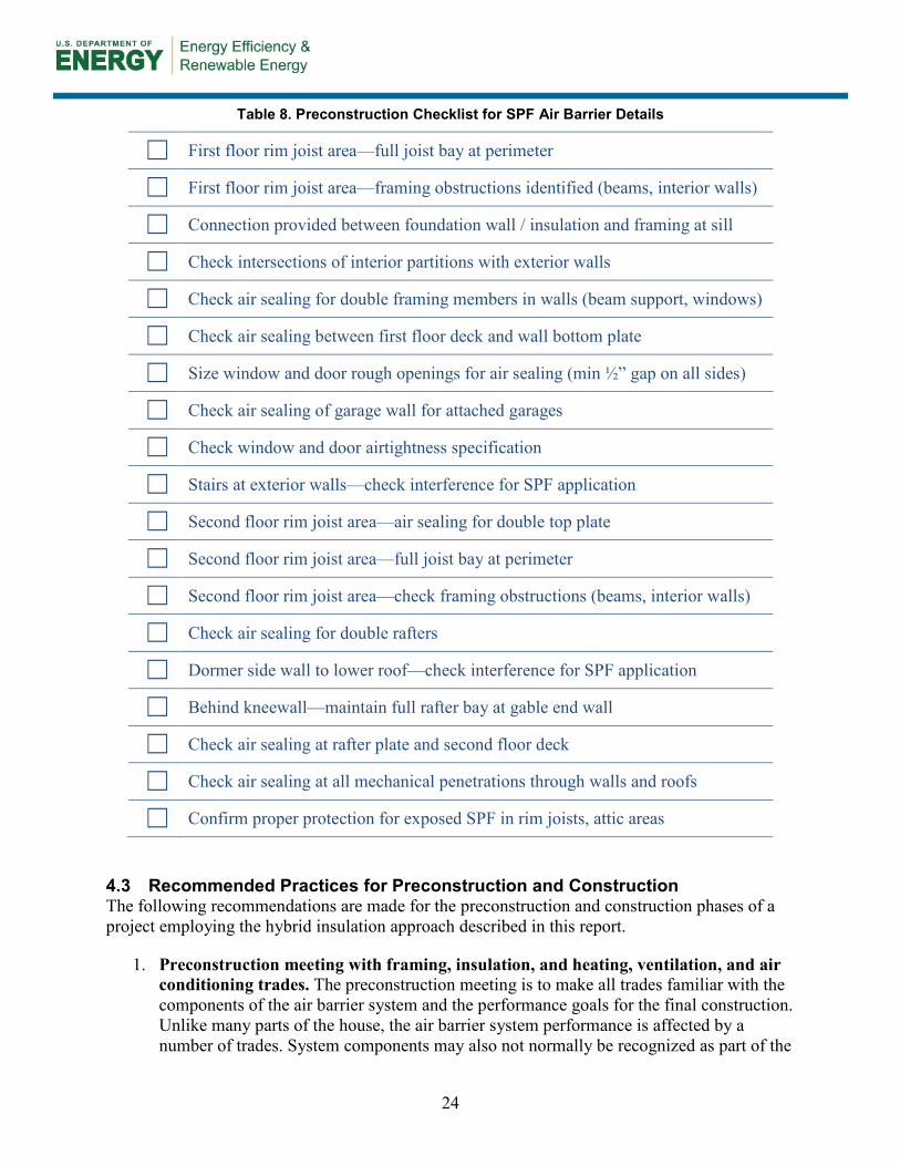
24
Table 8. Preconstruction Checklist for SPF Air Barrier Details
☐ First floor rim joist area—full joist bay at perimeter
☐ First floor rim joist area—framing obstructions identified (beams, interior walls)
☐ Connection provided between foundation wall / insulation and framing at sill
☐ Check intersections of interior partitions with exterior walls
☐ Check air sealing for double framing members in walls (beam support, windows)
☐ Check air sealing between first floor deck and wall bottom plate
☐ Size window and door rough openings for air sealing (min ½” gap on all sides)
☐ Check air sealing of garage wall for attached garages
☐ Check window and door airtightness specification
☐ Stairs at exterior walls—check interference for SPF application
☐ Second floor rim joist area—air sealing for double top plate
☐ Second floor rim joist area—full joist bay at perimeter
☐ Second floor rim joist area—check framing obstructions (beams, interior walls)
☐ Check air sealing for double rafters
☐ Dormer side wall to lower roof—check interference for SPF application
☐ Behind kneewall—maintain full rafter bay at gable end wall
☐ Check air sealing at rafter plate and second floor deck
☐ Check air sealing at all mechanical penetrations through walls and roofs
☐ Confirm proper protection for exposed SPF in rim joists, attic areas
4.3 Recommended Practices for Preconstruction and Construction The following recommendations are made for the preconstruction and construction phases of a project employing the hybrid insulation approach described in this report.
1. Preconstruction meeting with framing, insulation, and heating, ventilation, and air conditioning trades. The preconstruction meeting is to make all trades familiar with the components of the air barrier system and the performance goals for the final construction. Unlike many parts of the house, the air barrier system performance is affected by a number of trades. System components may also not normally be recognized as part of the

25
air barrier system. It should also be made known that the system will be tested and that all trades involved may be required to perform remedial work to address air barrier deficiencies.
2. Plan construction schedule with pause for air barrier test. The early blower door test should be treated like a plumbing inspection (see Section 3.1.1 above) where work is brought to the ready-for-inspection stage, the inspection and testing is performed, and then work is allowed to proceed. This allows for remedial work to be accomplished with the minimum amount of lost time and effort. It should be noted that depending on the enclosure assemblies selected, this construction pause does not need to apply to exterior cladding and finishing work or installation of heating, ventilation, and air conditioning, electrical, and plumbing systems.
3. Plan for trade to follow-up on air barrier test results. This should include a scope of work for the repair work and preparation with the tools and supplies needed to fix the expected holes. Airtightness test results (good or bad) should also be made available to anyone involved in executing the work.
4.4 Recommended Practices for Quality Control The following recommendations are made to support on-site quality control activities for a project employing the hybrid insulation approach described in this report.
1. Be familiar with potential trouble spots. The inspectors (who may include both the Home Energy Rating System rater and the builder’s site supervisor) should be familiar with the common problem areas listed in Table 8 and should have a list of enclosure penetrations that will be made after the airtightness test.
2. Perform blower door test at completion of the air barrier system. The blower door test should be performed with the insulation installer present or else a marking system should be used to identify air leakage paths that require remedial work (see Figure 4 as an example). The marking system could include a colored paint code that indicates the type of remedial work required. For example, red paint is read as “leak needing to be fixed,” green paint is read as “leak has been fixed,” etc. Otherwise, require that repair work be completed immediately and do not allow construction to continue until the test is passed. Please note that the blower door test is meant to be a tool that helps improve the airtightness of the building rather than its more common role as a compliance test. It is important to meet the target airtightness number, but from a performance perspective, the objective is to reduce the enclosure air leakage to the lowest possible amount for each house.
3. After the airtightness test, each penetration must be inspected. The airtightness test happens early enough that many mechanical, electrical, and plumbing penetrations will not be in place at the time of the test. This is the desired condition because it allows the test to focus on deficiencies in the enclosure. As intakes, exhaust vents, plumbing stacks, electrical boxes, and other penetrations are installed, each instance must be inspected to ensure that the integrity of the air barrier system is maintained. With good details and attentive supervision, no further testing of the enclosure should be required.

26
4. Review house for combustion safety.3 Only sealed-combustion, power-vented combustion appliances are recommended for houses build to stringent airtightness specifications. Confirm proper installation of these appliances by qualified contractor. Check that an appropriate source of make-up air is provided for dryers.4 Carbon monoxide detectors are required to be installed if the house has combustion appliances.
5. Commission mechanical ventilation system. All houses built to stringent airtightness specifications require small amounts of controlled mechanical ventilation. This can be accomplished with an exhaust system, a supply system or a balanced system. For ventilation systems to ventilate they must be properly commissioned and the correct operation and maintenance procedures must be explained to the homeowner. Continuous operation of a ventilation system typically controls indoor contaminants more effectively than infrequent operation. Proper sizing is important (Lstiburek 2006). Undersizing and infrequent operation can lead to elevated levels of indoor contaminants. Oversizing can lead to excessive energy consumption and elevated levels of interior moisture in humid climates. Oversized ventilation systems that run continuously should be avoided.
4.5 Implications for Winter Construction Costs The impact of the hybrid insulation approach on winter construction costs was not an expected outcome of this research and the cost implications were not closely monitored, but the impact is significant enough to be discussed as an outcome of this research.
In cold climates, cold weather construction is an important concern for production builders. The financial considerations are significant: the ability to maintain a 12-month production schedule significantly increases annual production; cold weather affects the construction schedule and productivity through the winter months; and the costs to provide supplemental heat for the house during winter construction can be significant.
This technology package is designed for cold climate applications. It is not a surprise, of course, that cold climate building locations experience very cold temperatures for at least part of the construction season. In areas like Wyandotte (which is relatively far south in zone 5), the winter construction season goes from late December to the end of March. During this time, the ground is likely to be frozen down to the frost depth of 2–3 ft and the mean air temperature ranges from 22.8° to 28.2°F (see below)—i.e., typically below the freezing point. Further north in International Falls, the maximum monthly temperatures are below freezing during the same time.
For this winter construction period, builders must provide heat to the building to prevent freezing of construction materials (including the concrete foundation as it cures) and to allow for finishing work to proceed. In a typical cold climate production process, construction heat may be provided from the end of the framing stage to the point where the mechanical system can be turned on and operated. The time period could be from several weeks to two full months depending on how quickly the house can be closed in and the mechanical system installed. Propane heaters placed in the basement of the house typically provide construction heat, although some builders use electric heat if electricity is available. Most propane heaters add heat but also add a significant
3 For more information about combustion safety, see www.cpsc.gov/cpscpub/pubs/452.html and www.epa.gov/iaq/homes/hip- combustion.html 4 2006 International Residential Code, Section G2439.4, and 2006 International Fuel Gas Code, Section 614.5.

27
amount of moisture in the form of water vapor to the enclosed volume of the house under construction. If the house is open enough to air movement, this may not be a problem, but as the house gets “dried-in” ventilation must be provided to prevent an accumulation of moisture in construction materials that may lead to condensation and mold growth.
The cost of providing heat to the partially completed house during the winter months can be significant. Production builders building on compressed schedules typically allow for $1,200–$1,600 for an average 2,400-ft2 home. Not all houses in the schedule will require the same amount of heat. Some will use less, but houses that are built in the coldest part of the winter in cold climates may use $3,500–$5,000 in construction heat. This could mean approximately $500/wk of winter construction per house. These costs, even in best-case scenarios, are on the same order of magnitude of some of the energy efficiency improvements that are often recommended for cold climate construction—and these energy efficiency measures often have a permanent impact on the operating cost of the home.
There are several factors that contribute to this cost:
• Outdoor air temperature
• Airtightness of building enclosure
• Length of time from completion of framing to operation of mechanical system
• Source of energy
• Cost of energy.
For production builders operating on a 12-month construction schedule, only the last four factors can be addressed. The connection to the hybrid wall system explored by this report can address each of these. First, the air barrier system is complete at an early stage of construction—perhaps days or a week after the framing is complete. At this time, the building airtightness is close to its final number—based on Wyandotte results < 1.5 ACH50 can be expected. The use of SPF also allows the walls and roof to be considered insulated at this stage. At Wyandotte, after the insulating sheathing, windows, and spray foam were complete, the above-grade walls would be R-22 and the roof would be R-24. The remaining wall, roof, and basement insulation would be installed at a later time.
Once the air control layer and thermal control layer is established, less heat will need to be provided to maintain working conditions (a direct cost savings for the builder) and other sources of heat can now be considered (reducing the risk of moisture and combustion gas problems; may save cost). Propane heaters are favored because of their portability and high heat outputs but must be properly vented to safely remove combustion gases from the interior working environment. If electricity is available at the house, electric heaters can be used—thereby reducing the amount of moisture added to the house and removing combustion gas concerns. In addition, off-peak power rates may provide builders with a savings on the cost of energy if the houses are heated at night on a timer that takes advantage of lower rates. During the day when the sun contributes heat to the building and the doors are often opened for tradespeople coming and going through the house, the temperature is allowed to fall until the following evening when the timer turns the heater back on.

28
The cost of winter construction heat is often an allowance in the overall construction budget for a project and does not appear in the construction cost of an individual unit. The hybrid insulation approach can reduce both the duration and magnitude of these “external” costs, so BSC recommends that the benefits described above be considered as part of the system engineering of the house design.
4.6 Future Considerations The hybrid insulation approach employed for the Wyandotte enclosure is ready for deployment in a production setting. Although it is likely that this approach will not allow for even greater nominal R-values (given spatial and material constraints), the assemblies described in this report will meet short-term requirements for high R-value enclosures. Additional refinements may be explored, including:
• Removal of the remaining OSB panels used for shear strength if the ccSPF can be used to meet these loads
• Optimization of materials to further decrease cost
• Experimentation with single-point, fast airtightness tests
• Experimentation with house design to reduce material use and streamline ccSPF installation.
BSC will continue to collect data on test results and construction issues until completion of the construction program.

29
References
Broniek, J.; Brozyna, K.; Stecher, D. (2010). “Evaluating R40 Above Grade Walls for a Production Built Zero Energy House.” Proceedings of Thermal Performance of Exterior Envelopes of Whole Buildings XI, Portland, USA.
BSC. (2010a). “Designs that Work - Cold Climate: Habitat for Humanity High R-Value Prototype.” Building Science Corporation, Somerville, MA. www.buildingscience.com/ documents/case-studies/cs-ma-westford-hfh/. Accessed January 3, 2011.
BSC. (2010b). “RR-1004: 2010 Community Scale Evaluations.” Building Science Corporation, Somerville, MA. www.buildingscience.com/documents/ba-2010-annual-report-files/rr-1004-2010-community-scale-evaluations/. Accessed January 3, 2011.
Grin, A.; Lstiburek, J. (2012). Moisture and Structural Analysis for High Performance Hybrid Wall Assemblies. DOE/GO-102012-3527. Golden, CO: National Renewable Energy Laboratory.
Kerrigan, P. (2006). Venture West Field Report. Forthcoming publication—NREL.
Lstiburek, J. (2006). Builder’s Guide to Cold Climates. Building Science Press, Westford, MA.
Lstiburek, J.; Grin, A. (2010). “RR-1004: Building America Special Research Project—Advanced Framing Deployment.” Building Science Corporation, Somerville, MA. www.buildingscience.com/documents/reports/rr-1004-ba-special-research-advanced-framing-deployment/. Accessed January 3, 2011.
Lstiburek, J. (2008). BSI-001: The Perfect Wall. Building Science Corporation, Somerville, MA. www.buildingscience.com/documents/insights/bsi-001-the-perfect-wall?topic=doctypes/insights. Accessed November 13, 2012.
Lstiburek, J. (2009). BSI-018: Westford House. Building Science Corporation, Somerville, MA. www.buildingscience.com/documents/insights/bsi-018-westford-house?searchterm=westford+insight. Accessed November 13, 2012.
Lukachko, A.; Bergey, D. (2010). “’Wyandotte NSP2’ Cold Climate Commercially Viable Energy Efficiency Solution Package” Building Science Corporation, Somerville, MA. Forthcoming publication - NREL.
Lukachko, A.; Grin, A. (2011). “4.3.3 Wyandotte NSP2 Final Technical Report” Building Science Corporation, Somerville, MA. Forthcoming publication - NREL.
Lukachko, A.; Gates, C.; Straube, J. (2011). “3.1.2 Final Advanced New Construction Measure and/or Strategy Guideline”. Forthcoming publication—NREL.
Straube, J.; Smegal, J. (2009). “RR-0903: Building America Special Research Project—High-R Walls Case Study Analysis.” Building Science Corporation, Somerville, MA. www.buildingscience.com/documents/reports/rr-0903-building-america-special-research-project-high-r-walls/. Accessed January 3, 2011.

30
Straube J. (2011). BSD-163: Controlling Cold-Weather Condensation Using Insulation. Building Science Corporation, Somerville, MA. www.buildingscience.com/documents/digests/ bsd-controlling-cold-weather-condensation-using-insulation. Accessed November 13, 2012.
Ueno, K.; Bergey, D.; Wytrykowska, H. (2012). “4.1.2 Transformations, Inc. Draft Technical Report.” Forthcoming publication—NREL.

31
Appendix: BEopt Energy Analysis
Preliminary energy analysis using BEopt was completed for the Wyandotte technology package in 2010 and then updated in 2011 to reflect the as-built construction. The following analysis was completed in 2012 to account for minor changes to the technology specification and also to provide a basis for recommendations for other Cold Climate projects that do not have Wyandotte’s project-specific conditions.
The experimental city-owned GSHP wells, each shared between houses, were a programmatic requirement of the Wyandotte houses. The cost of this system dominates the total cost for energy-related upgrades, and renders the houses as built quite uneconomical without special financing for the GSHP (“As-built”). To isolate this aspect, the energy modeling in Table 9 shows a house as built, and a house with identical enclosure but a conventional furnace and split system AC, as is usual for new construction in the area (“Recommended”). The cost assigned to the GSHP includes the reported cost for wells and the heat pump itself. The third modeled case (“Standard Practice”) is typical of houses that the builders involved in this project build elsewhere in the region.
Table 9. BEopt Inputs for Wyandotte Builder Standard Practice, BSC Recommendations, and As-Built Specification
Parameter Standard Practice
Recommended Package
As-Built Package With GSHP
Roof R-38 FB Batt R-30 ccSPF with R-19 FG batt below
R-30 ccSPF with R-19 FG batt below
Walls R-19, 2 × 6 16 in. o.c.
R-10 EPS, R-10 ccSPF, R-32 total
R-10 EPS, R-10 ccSPF, R-32 total
Foundation Uninsulated R-10 on walls R-10 on walls
Windows U = 0.34, SHGC = 0.30
U = 0.28, SHGC = 0.29
U = 0.28, SHGC = 0.30
Infiltration 3.2 ACH50 1.3 ACH50 1.3 ACH51
Heating 92% AFUE furnace 92% AFUE Furnace 9.2 HSPF GSHP
Cooling 14 SEER 14 SEER 18 SEER GSHP Ductwork In unvented attic In conditioned space In conditioned space
DHW 0.80 EF gas 0.80 EF gas EF 0.98 electric with desuperheater
Modelling of both the “Recommended” and “As-built” packages (109.48 106 Btu/yr and 104.4 106 Btu/yr, respectively) resulted in significantly lower estimated whole house energy use that the Building America Benchmark (BAB) technology package and the local builders’ standard practice (198.65 106 Btu/yr and 158.59 106 Btu/yr, respectively). The “As-built” package is an estimated 41% savings over the BAB. The “Recommended” package is a 38% savings over the BAB. The estimated source energy use by end use is provided in Figure 7 below.

32
Figure 7. Wyandotte estimated source energy by end use
However, the annualized energy-related cost (construction cost for measures + energy cost over a 30-year study period) for the “Recommended” and “As-built” packages is significantly different (see Figure 8 below).
Figure 8. Savings versus benchmark, annualized cost
Despite the high cost of the GSHP system used in Wyandotte, BSC remains interested in further understanding the impact of the district system when measured energy use data is available for the project.
0
50
100
150
200
250
BAB standard recommend as-built
Sour
ce E
nerg
y (1
06Bt
u/yr
) Misc
Lights (E)
Lg. Appl.
Hot Water
HVAC Fan/Pump (E)
Cooling (E)
Heating (E)
Heating (G)
standard
recommend
as-built
$1,200.00
$1,400.00
$1,600.00
$1,800.00
$2,000.00
$2,200.00
$2,400.00
$2,600.00
$2,800.00
$3,000.00
0% 10% 20% 30% 40% 50%
Annu
alize
d En
ergy
Rel
ated
Cos
t [$/
yr]
Source Energy Savings

buildingamerica.gov
DOE/GO-102013-3941 ▪ December 2013
Printed with a renewable-source ink on paper containing at least 50% wastepaper, including 10% post-consumer waste.