hydra adaptive system - calor tehnice hydra it_en.pdf · the product was developed using the most...
TRANSCRIPT

Hydra Adaptive SystemRefrigeratori di liquido e pompe di calore ad aria, per esterno
Air cooled liquid chillers and heat pumps for outdoor
REF R407cPf = 12,9 ÷ 37,2 kWPt = 14.9 ÷ 39.7 kWMod. 051 ÷ 151
Tonon Forty S. p. A. - Via Concordia 1, Zona Industriale - 31046 Oderzo (TV) ITALY Tel. +39 0422 2091111 Fax +39 0422 209102 e-mail: tonon@tonon. it - web: www. tonon. it
Il costruttore si riserva il diritto di apportare qualsiasi modifi ca al prodotto senza alcun preavvisoThe manufacturer reserves the right to make any changes to the product without prior notice


SERIE HYDRA
3
CARATTERI GENERALI
Refrigeratori e pompe di calore ad alta efficienza dimensionati per l’utenza domestica e commerciale.Le unità HYDRA sono equipaggiate con kit idronico fornito di serie a bordo macchina ed utilizzano un nuovo dispositivo di regolazione che permette un ottimo funzionamento dell’apparecchiatura senza necessità di installazione del serbatoio di accumulo inerziale. Tale soluzione, pronta all’uso, permette di facilitare le operazioni di installazione, riducendone gli spazi ed i relativi costi, oltre ad evitare inutili dispersioni di calore verso l’esterno. Le unità sono provviste di controllo della ventilazione che permette di ottimizzarne il funzionamento anche con ridotte temperatura dell’aria esterna e, nel contempo, di ridurre l’emissione sonora durante l’attività nelle ore notturne.Il dispositivo di regolazione ADAPTIVE permette di gestire in maniera appropriata accensioni e spegnimenti del compressore in modo da ottimizzare la produzione di acqua refrigerata/riscaldata in unità con carichi termici bassi, senza accumulo, attraverso la modifica dinamica dei set-point e dei differenziali di lavoro sia in funzionamento chiller che in funzionamento pompa di calore. La funzione analizza il tempo effettivo di funzionamento del compressore dalla richiesta di accensione alla richiesta di spegnimento della termoregolazione e lo confronta con il tempo minimo di funzionamento impostato. Se il tempo effettivo di funzionamento è inferiore al tempo minimo, ad ogni spegnimento del compressore, al SET POINT chiller e pompa di calore e al DIFFERENZIALE chiller e pompa di calore viene associato un valore fisso e un valore proporzionale dato dalla differenza tra tempo minimo e tempo effettivo moltiplicato per il valore impostato. Il set-point e il differenziale sono diminuiti delle stesse quantità fisse se il tempo di funzionamento del compressore è superiore al tempo impostato.
Lo sviluppo del prodotto è stato realizzato utilizzando le più attuali tecnologie di progettazione e successivamente testato nei nostri laboratori al fine di garantire efficienza ed una assoluta affidabilità nel tempo.La gamma di prodotti HYDRA è un ulteriore tassello a completamento della panoramica prodotti idronici per il condizionamento, che spazia dai gruppi di produzione caldo / freddo alle unità terminali di impianto.
CARATTERISTICHE TECNICHE UNITA’
Struttura le unità sono assemblate su struttura autoportante completamente realizzata in lamiera zincata con panelli rimovibili per un agevole manutenzione, il tutto verniciato con polveri poliesteri essicate a forno di colorazione Ral 9018.
Compressore ermetico Scroll di primaria marca particolarmente indicato per l’applicazione nel condizionamento civile, in grado di garantire una elevata efficienza e, nel contempo, livelli di rumorosità e vibrazioni decisamente contenuti. Installato su supporti antivibranti è fornito di protezione termoamperometrica a protezione del motore
Condensatori di raffreddamento di tipo a pacco alettato realizzati con tubi in rame mandrinati in un pacco alettato in alluminio e telaio di supporto dello scambiatore in acciaio zincato. Su richiesta è possibile la versione con alettatura in rame o alluminio preverniciato per installazioni in atmosfere particolarmente aggressive.
Evaporatore ad espansione secca di tipo a piastre saldobrasate in acciaio inox Aisi 316 isolato con materassino anticondensa a cellule chiuse di elevato spessore. Provvisto di attacchi idraulici filettati per un agevole collegamento all’impianto utilizzatore. Su richiesta è possibile la fornitura della resistenza di sicurezza antigelo.
Sezione ventilante composta da ventilatore/i elicoidali con pale riportate e motore direttamente accoppiato di tipo a statore rotante. Il ventilatore è installato su boccaglio opportunamente sagomato per garantire la migliore prestazione aeraulica ed è equipaggiato con griglia di protezione antinfortunistica in acciaio zincato verniciato.
GENERAL CHARACTERISTICS
Refrigerators and high-efficiency heat pumps designed for residential and commercial use.Hydra units are equipped with hydronic kits standard on-board the machine and use a new regulation device that allows excellent operation without the need to install an inertial accumulation tank.This ready-to-use solution facilitates installation, reducing space and the relative costs in addition to avoiding the useless dispersion of heat to the outside. The have a ventilation control that optimizes operation even with low outside air temperatures and, at the same time, reduces noise when operating at night.The adaptive regulation device turns the compressor on and off in a way that optimizes the production of refrigerated/heated water in units with load thermal loads, without accumulation, through the dynamic modification of set-points and working differentials in both chiller and heat-pump operation. The function analyzes the compressor’s effective operating time between the thermostat’s on and off requests and compares it to the minimum set operating time. If the effective operating time is less than the minimum time, every time the compressor is turned off, the chiller and heat pump set point and chiller differential is associated with a fixed value and a proportional value calculated based on the difference between the minimum and effective time multiplied by the value set. The set point and differential are decreased by the same fixed quantity if the compressor’s operating time is longer than the time set.
The product was developed using the most current design technologies and tested in our laboratories to guarantee efficiency and absolute reliability over time.The Hydra product line is another tile in our mosaic of hydronic products for air-conditioning that range from special hot/cold production units to plant terminal units.
UNIT TECHNICAL CHARACTERISTICS
Structure the units are assembled on a frame made entirely of galvanized sheet metal with removable panels for easy maintenance and all painted with oven-baked RAL 9018 polyester powder.
Compressor leading brand hermetic scroll particularly indicated for civil air-conditioning applications and able to provide high-efficiency and, at the same time, decidedly modest levels of noise and vibration. Installed on vibration-damping supports, the motor is protected by a circuit-breaker.
Pack-type, finned cooling condensers made of expanded copper tubes in an aluminum finned pack and frame supporting the galvanized steel exchanger. On request, a version an be supplied with prepainted copper or aluminum fins for installation in especially aggressive environments.
Plate-type, dry-expansion evaporator braise-welded in AISI 316 stainless steel insulated with a thick, closed-cell anti-condensate pad. Provided with threaded water fittings for easy connection to the user’s plant. Upon request, we also supply frost-prevention heating elements.
Ventilating section consisting of helical fan(s) with blades and motor with direct, rotating stator coupling. The ventilator is installed on a suitably-shaped nozzle to provide the best air-hydraulic performance and is equipped with an safety grill made of painted galvanized steel.

SERIE HYDRA
4
Circuito frigorifero completamente cablato e sigillato realizzato con tubo di rame comprendente: filtro deidratore, valvola termostatica con equalizzazione esterna, pressostati di sicurezza su lato alta e bassa pressione, prese di pressione per riempimento e scarico liquido frigorigeno ed eventuale collegamento dei manometri di controllo. Il lato bassa pressione viene isolato con materassino anticondensa a cellule chiuse di elevato spessore.
Quadro elettrico completamente cablato all’interno di una scatola in acciaio, realizzato secondo le più rigorose normative europee. Il circuito di potenza è previsto per alimentazione a 400/3/50 V/ph/Hz. Il circuito ausiliario è provvisto di una protezione magnetotermica separata. Regolazione e controlli sono gestiti da una unità a microprocessore in accoppiamento ai dispositivi di sicurezza previsti a bordo macchina o collegati esternamente.La programmazione, il settaggio ed il controllo dei parametri di funzionamento vengono eseguite direttamente sul modulo a display posizionato all’esterno del quadro elettrico
Principali funzioni della regolazione:
Principali funzioni della regolazione ADAPTIVE:- Controllo dell’inserimento del compressore in funzione della
temperatura acqua di ritorno o, su richiesta, in mandata all’impianto.
- Impostazione automatica e dinamica del Set Point di lavoro gestita in funzione della valutazione degli effettivi tempi di funzionamento e di attesa del compressore. Il sistema permette il controllo modulante della pompa di circolazione al fine di mantenere la temperatura dell’acqua di mandata il più possibile prossima al valore ottimale anche nella fase di messa a regime dell’impianto .
- Segnalazione allarmi ottica ed acustica con visualizzazione a display del tipo di allarme intervenuto o, se più di uno, della sequenza degli stessi in ordine temporale.
- Possibilità di gestire una pompa esterna.- Conteggio del tempo di funzionamento per il compressore e
la pompa.- Memorizzazione dei dati di programmazione in caso di
mancanza di alimentazione al sistema.- Memorizzazione storici allarmi fino ad un massimo di 50
segnalazioni.- Possibilità di controlloare in funzione della Temperatura
esterna l’attivazione del compressore (set point dinamico).- Controllo della ventilazione in funzione della temperatura
dell’aria esterna.- Controllo combinato in temperatura / pressione della funzione
di sbrinamento antigelo (per unità a pompa di calore).
Accessori a richiesta:
- MHL manometri lato alta / bassa pressione;- RAE resistenza antigelo evaporatore;- SAB supporti antivibranti di base;- KRC base Kit di remotazione controlli semplice;- KRC top Kit di remotazione controlli completo;- RCA resistenza carter compressori;- DCP controllo condensazione a pressione per temp. aria esterna fino a -10 °C.
Refrigeration circuit completed wired and sealed, made with copper tube, including: dehydrator filter, thermostatic value with external equalization, safety pressure switch on the high and low pressure side, pressure fitting for filling and discharging refrigerant liquid and possible connection of control manometers. The low-pressure side is insulated with a thick, closed cell anti-condensation pad.
Electrical panel completely wired inside a steel box constructed in conformity with the most rigorous European standards. The power circuit is prepared for 400/3/50 V/ph/Hz power. The auxiliary circuit has separate circuit-breaker protection. Regulation and control are handled by a microprocessor coupled to on-board or externally-connected safety devices.The programming, setting and control of operating parameters is performed directly on the display module located on the outside of the control panel
Main regulation functions:
Main adaptive regulation functions:- Compressor control as a function of the temperature of
the return water or, upon request, the water output by the plant.
- Automatic and dynamic set points managed as a function of an evaluation of the effective compressor operating and waiting times. The system allows modulating control of the circulation pump to maintain the temperature of the output water as close as possible to the optimal value, even during the plant start-up phase.
- Visual and acoustic alarms with a display of the type of alarm or, if more than one, of their sequence in order of time.
- Ability to manage an external pump.- Counting pump and compressor operating times.- Storing programming data in the event of a power failure.- Storing alarm history for a maximum of 50 reports.- Ability to control compressor activation as a function of the
external temperature (dynamic set point).- Ventilation control as a function of the temperature of the
outside air.- Combined temperature/pressure control of the defrosting
function (for heat pumps).
Accessories available upon request:
- MHL manometers on the high and low-pressure sides;- RAE evaporator frost-resistance;- SAB basic vibration-damping supports;- KRC basic simple remote control kit;- KRC top complete remote control kit;- RCA compressor guard heating element;- DCP condensation control based on pressure for temperature of external air up to -10 °C.

SERIE HYDRA
5
VERSIONE VERSION
/- Versione refrigeratore Chiller version
/HP Versione pompa di calore Heat pump version
TIPO REFRIGERANTE TYPE OF REFRIGERANT
C R407c R407c
CONFIGURAZIONE:
HYDRA/HP 081 C
HYDRA /HP 081 C
TIPOUNITA’
VERSIONE GRANDEZZATIPO
REFRIGERANTE
CONFIGURATION:
HYDRA/HP 081 C
HYDRA /HP 081 C
TYPE OF UNIT
VERSION LARGETYPE OF
REFRIGERANT
OPZIONE ACCUMULO INERZIALE:
Tutti i modelli possono essere equipaggiati con serbatoio di accumulo acqua inerziale posizionato sotto o a lato dell’apparecchiatura in base al modello.
BUFFER TANK OPTION:
All models can be fitted with a storage water tank in the bottom or at a side of the unit.
MODELLI 051 - 061 - 081 - 091 MODELS 051 - 061 - 081 - 091
Installazione inferiore. Bottom installation.
MODELLI 101 - 121 - 151 MODELS 101 - 121 - 151
Installazione a lato. Side installation.

SERIE HYDRA
6
MODELLI CHILLER HYDRACHILLER HYDRA MODELS 051 061 081 091 101 121 151
Potenzialità frigorifera / Cooling capacity kW 12,9 15,9 18,1 21,8 27,1 31,5 37,2
Potenzialità termica / Heating capacity kW - - - - - - -
Compressori scroll / Scroll compressors n° 1 1 1 1 1 1 1
Circuiti frigoriferi / Refrigerant circuits n° 1 1 1 1 1 1 1
Gradini di parzializzazione / Capacity steps n° 1 1 1 1 1 1 1
Tensione di alimentazione / Main supply voltage V/Hz/Ph 400/3/50 400/3/50 400/3/50 400/3/50 400/3/50 400/3/50 400/3/50
Potenza sonora LwA / Sound power LwA dB(A) 76,0 76,0 79,7 79,4 79,4 79,5 82,3
Pressione sonora LpA / Noise pressure LpA dB(A) 45,0 45,0 48,7 48,4 48,4 48,5 51,3
COMPRESSORE / COMPRESSOR*
Potenza nominale / Power input* kW 4,6 5,4 6,0 7,5 9,1 10,8 12,6
Corrente nominale / Current input* A 8,0 9,3 12,1 13,0 15,6 18,4 23,0
Corrente max / Max. current input A 11 13 17 20 22 27 35
Corrente di spunto / Starting current* A 66 74 98 123 127 167 175
SCAMBIATORE LATO IMPIANTO / USER PLANT SIDE
Scambiatore a piastre / Brazed plate heat exchanger n° 1 1 1 1 1 1 1
Scambiatore a fascio tubiero / Shell and tube heat exchanger n° - - - - - - -
Portata acqua / Water flow rate l/s 0,62 0,76 0,86 1,04 1,29 1,51 1,78
Perdite di carico / Pressure drops kPa 19,0 28,8 15,5 22,4 34,7 33,0 46,5
SEZIONE VENTILANTE / FAN SECTION
Ventilatori / Fans n° 2 2 2 2 2 2 4
Portata d’aria Tot / Total air flow m3/h 7300 6560 9600 9600 11500 11300 15700
Velocità di rotazione / Fan speed min-1 980 980 910 910 910 910 980
Potenza assorbita unitaria / Power input (single fan) kW 0,2 0,2 0,3 0,3 0,3 0,3 0,2
Corrente assorbita unitaria / Current input (single fan) A 1,0 1,0 1,3 1,3 1,3 1,3 1,0
ASSORBIMENTI ELETTRICI TOTALI / TOTAL ELECTRIC ABSORPTION
Potenza nominale / Power input kW 4,9 5,7 6,6 8,1 9,7 11,4 13,2
Corrente nominale / Current input A 10,0 11,3 14,6 15,5 18,1 20,9 27,0
Corrente max / Max. current input A 13,0 15,0 19,5 22,5 24,5 29,5 39,0
Corrente di spunto / Starting current A 68 76 101 126 130 170 179
POMPA DI CIRCOLAZIONE / WATER PUMP
Prevalenza esterna pompa / Pump externe pressure kPa 169 145 165 146 117 98 107
Potenza assorbita pompa / Pump power input kW 0,4 0,4 0,4 0,4 0,4 0,4 0,8
Corrente assorbita pompa / Pump current input A 1,4 1,4 1,4 1,4 1,4 1,4 3,0
VASO ESPANSIONE / SURGE TANK
Capacità / Volume l 6 6 6 6 6 6 6
Pressione max lato acqua / Max. water pressure kPa 300 300 300 300 300 300 300
Pressione Precarica azoto / Nitrogen pre-charge pressure kPa 150 150 150 150 150 150 150
DIMENSIONE E PESI / MEASUREMENTS AND WEIGHT
Lunghezza / Length mm 1220 1220 1420 1420 1670 1670 1540
Profondità / Width mm 430 430 520 520 620 620 1160
Altezza / Height mm 1115 1115 1215 1215 1400 1400 1300
Peso STD / STD weight Kg 165 168 255 270 310 325 380
Peso AP / AP weight Kg 0 0 0 0 0 0 0
SERBATOIO DI ACCUMULO OPZIONALE / OPTIONAL STORANGE TANK
Serbatoio di accumulo / Storage water tank l 70 70 70 70 100 100 100
DATI TECNICI CHILLER HYDRA TECHNICAL DATA CHILLER HYDRA
LegendaPOTENZA FRIGORIFERA: Acqua scambiatore impianto (ingresso/uscita) 12/7 °C Aria esterna 35 °CPOTENZA TERMICA: Acqua scambiatore impianto (ingresso/uscita) 39/45 °C Aria esterna 7 °CPressione sonora a 10 metri in campo libero
LegendaCOOLING CAPACITY: System exchanger water (inlet/outlet) 12/7 °C Outside air 35 °CHEATING CAPACITY: System exchanger water (inlet/outlet) 39/45 °C Outside air 7 °CSound power at 10 metre in free field

SERIE HYDRA
7
MODELLI POMPE DI CALORE HYDRA HTHEAT PUMPS HYDRA HT MODELS 051 061 081 091 101 121 151
Potenzialità frigorifera / Cooling capacity kW 12,9 15,9 18,1 21,8 27,1 31,5 37,2
Potenzialità termica / Heating capacity kW 14,9 17,5 19,8 24,2 29,9 35,1 39,7
Compressori scroll / Scroll compressors n° 1 1 1 1 1 1 1
Circuiti frigoriferi / Refrigerants circuits n° 1 1 1 1 1 1 1
Gradini di parzializzazione / Capacity steps n° 1 1 1 1 1 1 1
Tensione di alimentazione / Main supply voltage V/Hz/Ph 400/3/50 400/3/50 400/3/50 400/3/50 400/3/50 400/3/50 400/3/50
Potenza sonora LwA / Sound power LwA dB(A) 79,2 79,2 79,7 79,4 79,5 79,6 82,3
Pressione sonora LpA / Noise pressure LpA dB(A) 48,2 48,2 48,7 48,4 48,5 48,6 51,3
COMPRESSORE / COMPRESSOR*
Potenza nominale / Power input* kW 4,7 5,5 6,2 7,7 8,5 11,0 12,9
Corrente nominale / Current input* A 8 9 12 13 16 18 26
Corrente max / Max. current input* A 11 13 17 20 22 27 35
Corrente di spunto / Starting current A 66 74 98 123 127 167 175
SCAMBIATORE LATO IMPIANTO / USER PLANT SIDE
Scambiatore a piastre / Brazed plate heat exchanger n° 1 1 1 1 1 1 1
Scambiatore a fascio tubiero / Shell and tube heat exchanger n° - - - - - - -
Portata acqua / Water flow rate l/s 0,62 0,76 0,86 1,04 1,29 1,51 1,78
Perdite di carico / Pressure drops kPa 19,0 28,8 15,5 22,4 34,7 33,0 46,5
SEZIONE VENTILANTE / FAN SECTION
Ventilatori / Fans n° 2 2 2 2 2 2 4
Portata d’aria Tot / Total air flow m3/h 9570 9740 10240 10240 11940 11720 16020
Velocità di rotazione / Fan speed min-1 1310 1310 910 910 910 910 980
Potenza assorbita unitaria / Power input (single fan) kW 0,6 0,6 0,3 0,3 0,3 0,3 0,2
Corrente assorbita unitaria / Current input (single fan) A 2,8 2,8 1,3 1,3 1,3 1,3 1,0
ASSORBIMENTI ELETTRICI TOTALI / TOTAL ELECTRIC ABSORPTION
Potenza nominale / Power input kW 5,9 6,7 6,8 8,3 9,1 11,6 13,6
Corrente nominale / Current input A 13,6 14,9 14,6 15,5 18,1 20,9 29,5
Corrente max / Max. current input A 16,6 18,6 19,5 22,5 24,5 29,5 39,0
Corrente di spunto * / Starting current * A 72 80 101 126 130 170 179
POMPA DI CIRCOLAZIONE / WATER PUMP
Prevalenza esterna pompa / Pump externe pressure kPa 169 145 165 146 116 99 108
Potenza assorbita pompa / Pump power input kW 0,4 0,4 0,4 0,4 0,4 0,4 0,8
Corrente assorbita pompa / Pump current input A 1,4 1,4 1,4 1,4 1,4 1,4 3,0
VASO ESPANSIONE / SURGE TANK
Capacità / Volume l 6 6 6 6 6 6 6
Pressione max lato acqua / Max. water pressure kPa 300 300 300 300 300 300 300
Pressione Precarica azoto / Nitrogen pre-charge pressure kPa 150 150 150 150 150 150 150
DIMENSIONE E PESI / MEASUREMENTS AND WEIGHT
Lunghezza / Length mm 1220 1220 1420 1420 1670 1670 1540
Profondità / Width mm 430 430 520 520 620 620 1160
Altezza / Height mm 1115 1115 1215 1215 1400 1400 1300
Peso STD / STD weight Kg 170 176 268 285 325 332 398
Peso AP / AP weight Kg 0 0 0 0 0 0 0
SERBATOIO DI ACCUMULO OPZIONALE / OPTIONAL STORANGE TANK
Serbatoio di accumulo / Storage water tank l 70 70 70 70 100 100 100
DATI TECNICI POMPE DI CALORE HYDRA HP TECHNICAL DATA HEAT PUMPS HYDRA HP
LegendaPOTENZA FRIGORIFERA: Acqua scambiatore impianto (ingresso/uscita) 12/7 °C Aria esterna 35 °CPOTENZA TERMICA: Acqua scambiatore impianto (ingresso/uscita) 39/45 °C Aria esterna 7 °CPressione sonora a 10 metri in campo libero
LegendaCOOLING CAPACITY : System exchanger water (inlet/outlet) 12/7 °C Outside air 35 °CHEATING CAPACITY: System exchanger water (inlet/outlet) 39/45 °C Outside air 7 °CSound power at 10 metre in free field

SERIE HYDRA
8
Chill
er H
ydra
051
Te 25 30 32 35 40 42
Tu Pf Qw Pa PaT Pf Qw Pa PaT Pf Qw Pa PaT Pf Qw Pa PaT Pf Qw Pa PaT Pf Qw Pa PaT
6 13,9 0,66 3,7 4,3 13,4 0,64 4,1 4,7 13,1 0,62 4,3 4,9 12,6 0,60 4,6 5,2 11,9 0,57 5,2 5,8 11,6 0,55 5,4 6,0
7 14,3 0,68 3,8 4,4 13,7 0,65 4,2 4,8 13,4 0,64 4,4 5,0 12,9 0,62 4,7 5,3 12,2 0,58 5,2 5,8 11,8 0,57 5,5 6,1
8 14,6 0,70 3,9 4,5 14,1 0,67 4,3 4,9 13,7 0,66 4,5 5,1 13,4 0,64 4,7 8,6 12,7 0,61 5,3 5,9 12,3 0,59 5,5 6,1
9 15,2 0,72 3,9 4,5 14,6 0,70 4,3 4,9 14,2 0,68 4,5 5,1 13,9 0,67 4,8 5,4 13,2 0,63 5,3 5,9 12,8 0,61 5,6 6,2
10 15,5 0,74 4,0 4,6 14,9 0,71 4,4 5,0 14,6 0,70 4,6 5,2 14,2 0,68 4,8 5,4 13,5 0,64 5,4 6,0 13,0 0,62 5,6 6,2
11 16,0 0,76 4,0 4,6 15,4 0,73 4,4 5,0 15,0 0,72 4,7 5,3 14,7 0,70 4,9 5,5 13,9 0,66 5,4 6,0 13,4 0,64 5,7 6,3
12 16,7 0,80 4,1 4,7 16,1 0,77 4,5 5,1 15,7 0,75 4,7 5,3 15,3 0,73 4,9 5,5 14,5 0,69 5,5 6,1 14,0 0,67 5,7 6,3
13 17,1 0,82 4,1 4,7 16,4 0,78 4,5 5,1 16,0 0,76 4,7 5,3 15,7 0,75 5,0 5,6 14,8 0,71 5,6 6,2 14,3 0,68 5,8 6,4
14 17,6 0,84 4,2 4,8 16,9 0,81 4,6 5,2 16,5 0,79 4,8 5,4 16,1 0,77 5,0 5,6 15,2 0,73 5,6 6,2 14,7 0,70 5,9 6,5
15 18,1 0,86 4,2 4,8 17,4 0,83 4,7 5,3 16,9 0,81 4,9 5,5 16,5 0,79 5,1 5,7 15,6 0,75 5,6 6,2 15,1 0,72 6,0 6,6
Chill
er H
ydra
061
Te 25 30 32 35 40 42
Tu Pf Qw Pa PaT Pf Qw Pa PaT Pf Qw Pa PaT Pf Qw Pa PaT Pf Qw Pa PaT Pf Qw Pa PaT
6 17,2 0,82 4,2 4,8 16,5 0,79 4,6 5,2 16,1 0,77 4,9 5,5 15,6 0,74 5,2 5,8 14,7 0,70 5,9 6,5 14,2 0,68 6,2 6,8
7 17,6 0,84 4,2 4,8 16,9 0,81 4,7 5,3 16,5 0,79 4,9 5,5 15,9 0,76 5,3 5,9 15,0 0,72 6,0 6,6 14,5 0,69 6,3 6,9
8 18,0 0,86 4,4 5,0 17,3 0,83 4,8 5,4 16,9 0,81 5,1 5,7 16,5 0,79 5,3 5,9 15,6 0,74 6,0 6,6 15,1 0,72 6,3 6,9
9 18,7 0,89 4,4 5,0 17,9 0,86 4,9 5,5 17,5 0,84 5,1 5,7 17,1 0,82 5,4 6,0 16,2 0,77 6,1 6,7 15,6 0,75 6,4 7,0
10 19,1 0,91 4,4 5,0 18,3 0,88 5,0 5,6 17,9 0,85 5,2 5,8 17,5 0,83 5,5 6,1 16,5 0,79 6,1 6,7 16,0 0,76 6,5 7,1
11 19,6 0,94 4,5 5,1 18,9 0,90 5,0 5,6 18,4 0,88 5,3 5,9 18,0 0,86 5,5 6,1 16,9 0,81 6,2 6,8 16,4 0,78 6,5 7,1
12 20,5 0,98 4,6 5,2 19,7 0,94 5,1 5,7 19,2 0,92 5,3 5,9 18,8 0,90 5,6 6,2 17,7 0,85 6,3 6,9 17,1 0,82 6,6 7,2
13 20,9 1,00 4,6 5,2 20,1 0,96 5,1 5,7 19,6 0,94 5,4 6,0 19,2 0,92 5,6 6,2 18,0 0,86 6,4 7,0 17,5 0,83 6,7 7,3
14 21,5 1,03 4,7 5,3 20,7 0,99 5,2 5,8 20,1 0,96 5,5 6,1 19,7 0,94 5,7 6,3 18,5 0,89 6,4 7,0 18,0 0,86 6,7 7,3
15 22,1 1,06 4,8 5,4 21,2 1,01 5,3 5,9 20,7 0,99 5,5 6,1 20,2 0,97 5,8 6,4 19,0 0,91 6,4 7,0 18,4 0,88 6,9 7,5
Chill
er H
ydra
081
Te 25 30 32 35 40 42
Tu Pf Qw Pa PaT Pf Qw Pa PaT Pf Qw Pa PaT Pf Qw Pa PaT Pf Qw Pa PaT Pf Qw Pa PaT
6 19,4 0,93 4,9 5,9 18,7 0,89 5,5 6,4 18,3 0,87 5,7 6,7 17,7 0,85 6,2 7,2 16,9 0,81 7,0 8,0 16,4 0,79 7,4 8,3
7 19,9 0,95 5,0 5,9 19,1 0,91 5,5 6,5 18,7 0,89 5,8 6,8 18,1 0,86 6,3 7,2 17,3 0,82 7,1 8,1 16,8 0,80 7,5 8,4
8 20,4 0,97 5,1 6,1 19,6 0,94 5,7 6,6 19,2 0,92 6,0 6,9 18,8 0,90 6,3 7,2 17,9 0,86 7,1 8,1 17,5 0,84 7,5 8,5
9 21,1 1,01 5,1 6,1 20,4 0,97 5,7 6,7 19,9 0,95 6,0 7,9 19,5 0,93 6,3 7,3 18,6 0,89 7,2 8,1 18,1 0,87 7,5 8,5
10 21,6 1,03 5,2 6,2 20,8 0,99 5,8 6,7 20,3 0,97 6,1 7,0 19,9 0,95 6,4 7,4 19,0 0,91 7,3 8,2 18,5 0,88 7,6 8,6
11 22,3 1,06 5,2 6,2 21,4 1,02 5,8 6,8 20,9 1,00 6,1 7,1 20,5 0,98 6,5 7,4 19,6 0,94 7,3 8,3 19,1 0,91 7,7 8,7
12 23,3 1,11 5,3 6,2 22,4 1,07 5,9 6,8 21,9 1,05 6,2 7,1 21,5 1,02 6,5 7,5 20,4 0,98 7,4 8,4 19,9 0,95 7,8 8,7
13 23,8 1,13 5,3 6,3 22,9 1,09 5,8 6,9 22,3 1,07 6,2 7,2 21,9 1,05 6,6 7,5 20,9 1,00 7,5 8,4 20,3 0,97 7,9 8,8
14 24,4 1,17 5,4 6,4 23,5 1,12 6,0 7,0 23,0 1,10 6,3 7,3 22,5 1,08 6,6 7,6 21,5 1,03 7,6 8,5 20,9 1,00 8,0 8,9
15 25,1 1,20 5,5 6,4 24,2 1,15 6,1 7,1 23,6 1,13 6,4 7,4 23,1 1,11 6,7 7,7 22,0 1,05 7,6 8,5 21,5 1,03 8,1 9,0
Chill
er H
ydra
091
Te 25 30 32 35 40 42
Tu Pf Qw Pa PaT Pf Qw Pa PaT Pf Qw Pa PaT Pf Qw Pa PaT Pf Qw Pa PaT Pf Qw Pa PaT
6 23,4 1,12 5,8 6,8 22,5 1,08 6,4 7,4 22,0 1,05 6,8 7,7 21,3 1,02 7,2 8,3 20,3 0,97 8,3 9,2 19,8 0,95 8,7 9,7
7 24,0 1,15 5,9 6,8 23,0 1,10 6,5 7,5 22,5 1,08 6,8 7,8 21,8 1,04 7,3 8,3 20,8 0,99 8,4 9,3 20,3 0,97 8,8 9,8
8 24,6 1,17 6,0 7,0 23,6 1,13 6,7 7,7 23,1 1,10 7,0 80 22,7 1,08 7,4 8,4 21,6 1,03 8,4 9,4 21,1 1,01 8,8 9,8
9 25,5 1,22 6,1 7,0 24,5 1,17 6,7 7,7 24,0 1,15 7,1 8,1 23,5 1,12 7,4 8,4 22,4 1,07 8,5 9,4 21,8 1,04 8,9 9,9
10 26,0 1,24 6,1 7,1 25,1 1,20 6,8 7,8 24,5 1,17 7,2 8,1 24,0 1,15 7,4 8,5 22,9 1,09 8,6 9,5 22,3 1,07 9,0 10,0
11 26,8 1,28 6,2 7,2 25,8 1,23 6,9 7,9 25,2 1,21 7,2 8,2 24,7 1,18 7,5 8,6 23,6 1,13 8,7 9,6 23,0 1,10 9,1 10,1
12 28,0 1,34 6,2 7,2 27,0 1,29 6,9 7,9 26,3 1,26 7,3 8,3 25,8 1,23 7,6 8,6 24,6 1,18 8,7 9,7 24,0 1,15 9,2 10,1
13 28,6 1,37 6,3 7,3 27,5 1,32 7,0 8,0 26,9 1,29 7,4 8,3 26,4 1,26 7,7 8,7 25,1 1,20 8,8 9,8 24,5 1,17 9,3 10,3
14 29,4 1,41 6,4 7,3 28,3 1,35 7,1 8,1 27,7 1,32 7,5 8,4 27,1 1,30 7,8 8,8 25,9 1,24 8,9 9,9 25,2 1,20 9,4 10,4
15 30,3 1,45 6,5 7,4 29,1 1,39 7,2 8,2 28,4 1,36 7,6 8,5 27,9 1,33 8,0 8,9 26,6 1,27 8,9 9,9 25,9 1,24 9,5 10,5
Chill
er H
ydra
101
Te 25 30 32 35 40 42
Tu Pf Qw Pa PaT Pf Qw Pa PaT Pf Qw Pa PaT Pf Qw Pa PaT Pf Qw Pa PaT Pf Qw Pa PaT
6 29,1 1,39 7,1 8,0 28,0 1,34 7,9 8,8 27,4 1,31 8,3 9,2 26,5 1,27 8,9 9,8 25,3 1,21 10,0 10,9 24,6 1,17 10,4 11,4
7 29,8 1,42 7,2 8,1 28,6 1,37 8,0 8,9 28,0 1,34 8,4 9,3 27,1 1,29 9,0 9,9 25,8 1,23 10,1 11,1 25,1 1,20 10,6 11,5
8 30,4 1,45 7,4 8,3 29,3 1,40 8,2 9,2 28,7 1,37 8,6 9,6 28,1 1,34 9,0 10,0 26,7 1,28 10,1 11,1 26,0 1,24 10,6 11,6
9 31,5 1,50 7,4 8,4 30,3 1,45 8,2 9,2 29,7 1,42 8,6 9,6 29,1 1,39 9,1 10,0 27,7 1,32 10,2 11,2 26,9 1,29 10,7 11,7
10 32,1 1,54 7,5 8,4 31,0 1,48 8,3 9,3 30,3 1,45 8,7 9,7 29,7 1,42 9,2 10,1 28,2 1,35 10,3 11,3 27,5 1,31 10,8 11,8
11 33,0 1,58 7,6 8,5 31,8 1,52 8,4 9,4 31,1 1,49 8,8 9,8 30,5 1,46 9,3 10,2 29,0 1,39 10,4 11,4 28,2 1,35 11,0 11,9
12 34,4 1,65 7,6 8,6 33,2 1,58 8,5 9,4 32,4 1,55 8,9 9,9 31,8 1,52 9,3 10,3 30,2 1,44 10,5 11,5 29,4 1,41 11,0 12,0
13 35,1 1,68 7,7 8,7 33,8 1,62 8,6 9,5 33,1 1,58 9,0 10,0 32,4 1,55 9,4 10,4 30,8 1,47 10,6 11,6 30,0 1,43 11,2 12,1
14 36,1 1,72 7,8 8,7 34,8 1,66 8,7 9,6 34,0 1,62 9,1 10,1 33,3 1,59 9,5 10,5 31,7 1,51 10,8 11,7 30,8 1,47 11,3 12,3
15 37,0 1,77 7,9 8,8 35,7 1,70 8,8 9,7 34,8 1,66 9,2 10,2 34,2 1,63 9,7 10,6 32,5 1,55 10,8 11,7 31,6 1,51 11,4 124
PRESTAZIONI CHILLER HYDRA PERFORMANCE CHILLER HYDRA
Legenda Legenda
Te [°C] temperatura aria esterna outside air temperatureTu [°C] temperatura acqua uscita scambiatore impianto plant exchanger outlet water temperaturePf [kW] potenza frigorifera cooling capacityPt [kW] potenza termica heat output
Qw [m3/h] portata acqua impianto plant water flow ratePa [kW] potenza assorbita compressori absorbed power - compressorsPaT [kW] potenza assorbita totale total absorbed power
Caselle vuote condizioni fuori dai limiti di funzionamento conditions outside functioning range

SERIE HYDRA
9
Chill
er H
ydra
121
Te 25 30 32 35 40 42
Tu Pf Qw Pa PaT Pf Qw Pa PaT Pf Qw Pa PaT Pf Qw Pa PaT Pf Qw Pa PaT Pf Qw Pa PaT
6 33,9 1,62 8,5 9,4 32,6 1,56 9,4 10,4 31,9 1,52 9,9 10,8 30,9 1,47 10,6 11,5 29,3 1,40 11,9 12,9 28,5 1,36 12,5 13,5
7 34,7 1,66 8,6 9,5 33,3 1,59 9,5 10,5 32,6 1,56 10,0 10,9 31,5 1,50 10,7 11,7 29,9 1,43 12,1 13,0 29,1 1,39 12,6 13,6
8 35,4 1,69 8,8 9,8 34,1 1,63 9,8 10,8 33,3 1,59 10,3 11,2 32,7 1,56 10,8 11,7 31,0 1,48 12,1 13,1 30,2 1,44 12,7 13,7
9 36,7 1,75 8,9 9,9 35,3 1,69 9,9 10,8 34,5 1,65 10,3 11,3 33,8 1,62 10,8 11,8 32,1 1,53 12,2 13,2 31,2 1,49 12,8 13,8
10 37,4 1,79 9,0 10,0 36,0 1,72 10,0 11,0 35,2 1,68 10,5 11,4 34,5 1,65 11,0 11,9 32,8 1,57 12,4 13,3 31,9 1,52 13,0 13,9
11 38,5 1,84 9,1 10,1 37,0 1,77 10,1 11,1 36,2 1,73 10,6 11,6 35,4 1,69 11,1 12,1 33,7 1,61 12,5 13,5 32,7 1,56 13,1 14,1
12 40,1 1,91 9,2 10,1 38,6 1,84 10,2 11,2 37,7 1,80 10,7 11,6 36,9 1,76 11,2 12,2 35,1 1,68 12,6 13,6 34,1 1,63 13,2 14,2
13 40,9 1,95 9,3 10,3 39,3 1,88 10,3 11,3 38,4 1,84 10,8 11,8 37,6 1,80 11,3 12,3 35,7 1,71 12,8 13,7 34,8 1,66 13,4 14,4
14 42,0 2,01 9,4 10,4 40,4 1,93 10,4 11,4 39,5 1,89 10,9 11,9 38,7 1,85 11,5 12,4 36,7 1,75 12,9 13,9 35,7 1,70 13,6 14,5
15 43,1 2,06 9,5 10,5 41,4 1,98 10,6 11,6 40,5 1,93 11,1 12,1 39,6 1,89 11,6 12,6 37,6 1,80 12,9 13,9 36,6 1,75 13,8 14,8
Chill
er H
ydra
151
Te 25 30 32 35 40 42
Tu Pf Qw Pa PaT Pf Qw Pa PaT Pf Qw Pa PaT Pf Qw Pa PaT Pf Qw Pa PaT Pf Qw Pa PaT
6 39,9 1,91 10,1 11,5 38,5 1,84 11,2 12,7 37,7 1,80 11,8 13,2 36,4 1,74 12,7 14,1 34,7 1,66 14,4 15,8 33,8 1,61 15,1 16,5
7 40,9 1,95 10,2 11,6 39,3 1,88 11,4 12,8 38,4 1,84 12,4 13,4 37,2 1,78 12,9 14,3 35,4 1,69 14,6 16,0 34,4 1,65 15,3 16,7
8 41,7 1,99 10,5 11,9 40,2 1,92 11,7 13,1 39,3 1,88 12,3 13,7 38,6 1,84 12,9 14,3 36,7 1,75 14,6 16,0 35,7 1,71 15,4 16,8
9 43,2 2,06 10,6 12,0 41,6 1,99 11,8 13,2 40,7 1,95 12,4 13,8 39,9 1,91 13,0 14,4 38,0 1,82 14,7 16,1 37,0 1,77 15,5 16,9
10 44,1 2,11 10,7 12,1 42,5 2,03 11,9 13,3 41,5 1,98 12,5 13,9 40,7 1,95 13,2 14,6 38,8 1,85 14,9 16,3 37,7 1,80 15,6 17,1
11 45,3 2,17 10,9 12,3 43,7 2,09 12,1 13,5 42,7 2,04 12,7 14,1 41,9 2,00 13,3 14,7 39,8 1,90 15,1 16,5 38,7 1,85 15,8 17,2
12 47,2 2,26 10,9 12,4 45,5 2,17 12,1 13,6 44,5 2,13 12,8 14,2 43,6 2,08 13,4 14,8 41,5 1,98 15,2 16,6 40,4 1,93 15,9 17,3
13 48,2 2,30 11,1 12,5 46,4 2,22 12,3 13,7 45,4 2,17 12,9 14,3 44,5 2,13 13,5 15,0 42,3 2,02 15,3 16,7 41,2 1,97 16,2 17,5
14 49,5 2,37 11,2 12,6 47,7 2,28 12,4 13,9 46,6 2,23 13,1 14,5 45,7 2,18 13,7 15,1 43,4 2,08 15,5 16,9 42,3 2,02 16,3 17,7
15 50,8 2,43 11,4 12,8 48,9 2,34 12,6 14,0 47,8 2,28 13,3 14,7 46,8 2,24 13,9 15,3 44,5 2,13 15,5 16,9 43,3 2,07 16,5 17,9
PRESTAZIONI CHILLER HYDRA PERFORMANCE CHILLER HYDRA
Legenda Legenda
Te [°C] temperatura aria esterna outside air temperatureTu [°C] temperatura acqua uscita scambiatore impianto plant exchanger outlet water temperaturePf [kW] potenza frigorifera cooling capacityPt [kW] potenza termica heat output
Qw [m3/h] portata acqua impianto plant water flow ratePa [kW] potenza assorbita compressori absorbed power - compressorsPaT [kW] potenza assorbita totale total absorbed power
Caselle vuote condizioni fuori dai limiti di funzionamento conditions outside functioning range

SERIE HYDRA
10
PRESTAZIONI POMPE DI CALORE HYDRA HT PERFORMANCE HEAT PUMPS HYDRA HT
PDC
Hyd
ra 0
51
Te 35 40 45 50
Tu Pt Qw Pa PaT Pt Qw Pa PaT Pt Qw Pa PaT Pt Qw Pa PaT
-5°C / 90% 10,5 0,50 3,6 4,8 10,4 0,50 4,0 5,2 10,4 0,50 4,4 5,6 10,3 0,49 4,9 6,1
0°C / 90% 12,5 0,60 3,7 4,9 12,4 0,59 4,1 5,3 12,3 0,59 4,6 5,8 12,2 0,58 5,1 6,3
5°C / 85% 14,4 0,69 3,7 4,9 14,2 0,68 4,2 5,4 14,0 0,67 4,6 5,8 13,8 0,66 5,1 6,3
7°C / 85% 15,4 0,74 3,7 4,9 15,2 0,72 4,2 5,4 14,9 0,71 4,7 5,9 14,7 0,70 5,2 6,4
10°C / 80% 16,6 0,79 3,8 5,0 16,3 0,78 4,2 5,4 16,0 0,76 4,7 5,9 15,7 0,75 5,3 6,5
15°C / 80% 19,4 0,93 3,8 5,0 19,0 0,91 4,3 5,5 18,5 0,89 4,8 6,0 18,1 0,87 5,3 6,5
PDC
Hyd
ra 0
61
Te 35 40 45 50
Tu Pt Qw Pa PaT Pt Qw Pa PaT Pt Qw Pa PaT Pt Qw Pa PaT
-5°C / 90% 12,3 0,59 4,1 5,3 12,2 0,58 4,7 5,9 12,1 0,58 5,3 6,5 12,1 0,58 6,0 7,2
0°C / 90% 14,6 0,70 4,2 5,4 14,4 0,69 4,8 6,0 14,2 0,68 5,4 6,6 14,1 0,68 6,1 7,3
5°C / 85% 16,8 0,80 4,3 5,5 16,5 0,79 4,8 6,0 16,2 0,77 5,4 6,6 16,0 0,76 6,1 7,3
7°C / 85% 17,9 0,85 4,3 5,5 17,5 0,84 4,8 6,0 17,2 0,82 5,5 6,7 16,9 0,81 6,2 7,4
10°C / 80% 19,2 0,92 4,3 5,5 18,8 0,90 4,9 6,1 18,4 0,88 5,5 6,7 18,1 0,86 6,2 7,4
15°C / 80% 22,4 1,07 4,4 5,6 21,8 1,04 4,9 6,1 21,3 1,02 5,5 6,7 20,8 0,99 6,2 7,4
PDC
Hyd
ra 0
81
Te 35 40 45 50
Tu Pt Qw Pa PaT Pt Qw Pa PaT Pt Qw Pa PaT Pt Qw Pa PaT
-5°C / 90% 14,2 0,68 4,8 5,4 14,1 0,67 5,3 5,9 14,0 0,67 5,9 6,5 14,1 0,67 6,5 7,1
0°C / 90% 16,7 0,80 4,9 5,5 16,5 0,79 5,5 6,1 16,4 0,79 6,1 6,7 16,5 0,79 6,8 7,4
5°C / 85% 19,1 0,91 4,9 5,5 18,8 0,90 5,5 6,1 18,7 0,89 6,1 6,7 18,6 0,89 6,9 7,5
7°C / 85% 20,3 0,97 4,9 5,5 20,0 0,96 5,5 6,1 19,8 0,95 6,2 6,8 19,7 0,94 6,9 7,5
10°C / 80% 21,8 1,04 4,9 5,5 21,5 1,03 5,5 6,1 21,2 1,01 6,2 6,8 21,0 1,00 7,0 7,6
15°C / 80% 25,4 1,21 4,9 5,5 24,8 1,19 5,5 6,1 24,4 1,17 6,2 6,8 24,1 1,15 7,0 7,6
PDC
Hyd
ra 0
91
Te 35 40 45 50
Tu Pt Qw Pa PaT Pt Qw Pa PaT Pt Qw Pa PaT Pt Qw Pa PaT
-5°C / 90% 16,9 0,81 6,0 6,6 16,7 0,80 6,7 7,3 16,6 0,79 7,4 8,0 16,6 0,79 8,1 8,7
0°C / 90% 20,0 0,95 6,1 6,7 19,7 0,94 6,8 7,4 19,6 0,93 7,6 8,2 19,5 0,93 8,5 9,1
5°C / 85% 22,9 1,09 6,1 6,7 22,5 1,08 6,9 7,5 22,3 1,06 7,7 8,3 22,1 1,06 8,6 9,2
7°C / 85% 24,3 1,16 6,1 6,7 23,9 1,14 6,9 7,5 23,6 1,13 7,7 8,3 23,5 1,12 8,7 9,3
10°C / 80% 26,2 1,25 6,1 6,7 25,7 1,23 6,9 7,5 25,3 1,21 7,8 8,4 25,1 1,20 8,8 9,4
15°C / 80% 30,5 1,46 6,1 6,7 29,8 1,42 6,9 7,5 29,2 1,40 7,7 8,3 28,8 1,38 8,8 9,4
PDC
Hyd
ra 1
01
Te 35 40 45 50
Tu Pt Qw Pa PaT Pt Qw Pa PaT Pt Qw Pa PaT Pt Qw Pa PaT
-5°C / 90% 21,6 1,03 6,7 7,3 21,3 1,02 7,4 8,0 21,1 1,01 8,1 8,7 20,9 1,00 8,9 9,5
0°C / 90% 25,2 1,20 6,8 7,4 24,9 1,19 7,6 8,2 24,5 1,17 8,4 9,0 24,3 1,16 9,3 9,9
5°C / 85% 28,6 1,37 6,8 7,4 28,1 1,34 7,6 8,2 27,7 1,32 8,5 9,1 27,4 1,31 9,5 10,1
7°C / 85% 30,3 1,45 6,8 7,4 29,8 1,42 7,6 8,2 29,3 1,40 8,5 9,1 28,9 1,38 9,5 10,1
10°C / 80% 32,4 1,55 6,9 7,5 31,8 1,52 7,7 8,3 31,3 1,50 8,6 9,2 30,8 1,47 9,6 10,2
15°C / 80% 37,4 1,79 6,8 7,4 36,6 1,75 7,7 8,3 35,9 1,71 8,6 9,2 35,3 1,68 9,7 10,3
PDC
Hyd
ra 1
21
Te 35 40 45 50
Tu Pt Qw Pa PaT Pt Qw Pa PaT Pt Qw Pa PaT Pt Qw Pa PaT
-5°C / 90% 25,1 1,20 8,5 9,1 24,8 1,19 9,4 10,0 24,7 1,18 10,5 11,1 24,6 1,18 11,6 12,2
0°C / 90% 29,2 1,40 8,7 9,3 28,9 1,38 9,7 10,3 28,6 1,37 10,8 11,4 28,4 1,36 12,0 12,6
5°C / 85% 33,2 1,58 8,7 9,3 32,7 1,56 9,8 10,4 32,2 1,54 10,9 11,5 31,9 1,52 12,2 12,8
7°C / 85% 35,2 1,68 8,8 9,4 34,6 1,65 9,8 10,4 34,1 1,63 11,0 11,6 33,7 1,61 12,3 12,9
10°C / 80% 37,6 1,80 8,9 9,5 36,9 1,76 9,9 10,5 36,3 1,74 11,1 11,7 35,9 1,71 12,5 13,1
15°C / 80% 43,4 2,08 8,9 9,5 42,5 2,03 10,0 10,6 41,6 1,99 11,2 11,8 40,9 1,96 12,5 13,1
Legenda Legenda
Te [°C] temperatura aria esterna outside air temperatureTu [°C] temperatura acqua uscita scambiatore impianto plant exchanger outlet water temperaturePf [kW] potenza frigorifera cooling capacityPt [kW] potenza termica heat output
Qw [m3/h] portata acqua impianto plant water flow ratePa [kW] potenza assorbita compressori absorbed power - compressorsPaT [kW] potenza assorbita totale total absorbed power
Caselle vuote condizioni fuori dai limiti di funzionamento conditions outside functioning range

SERIE HYDRA
11
PRESTAZIONI POMPE DI CALORE HYDRA PERFORMANCE HEAT PUMPS HYDRA HT
PDC
Hyd
ra 1
51
Te 35 40 45 50
Tu Pt Qw Pa PaT Pt Qw Pa PaT Pt Qw Pa PaT Pt Qw Pa PaT
-5°C / 90% 29,9 1,43 10,0 10,7 29,7 1,42 11,2 11,8 29,5 1,41 12,3 13,0 29,4 1,41 13,6 14,2
0°C / 90% 34,8 1,66 10,2 10,9 34,5 1,65 11,4 12,1 34,3 1,64 12,8 13,4 34,1 1,63 14,2 14,9
5°C / 85% 39,4 1,88 10,2 10,9 39,0 1,86 11,5 12,1 38,5 1,84 129 13,5 38,3 1,83 14,4 15,1
7°C / 85% 41,8 2,00 10,2 10,9 41,2 1,97 11,5 12,2 40,7 1,95 12,9 13,6 40,4 1,93 14,4 15,2
10°C / 80% 44,7 2,13 10,3 11,0 44,0 2,10 11,6 12,2 43,4 2,07 13,0 13,7 42,9 2,05 14,7 15,3
15°C / 80% 51,5 2,46 10,3 11,0 50,5 2,41 11,6 12,2 49,6 2,37 13,0 13,7 48,9 2,34 14,7 15,3
Legenda Legenda
Te [°C] temperatura aria esterna outside air temperatureTu [°C] temperatura acqua uscita scambiatore impianto plant exchanger outlet water temperaturePf [kW] potenza frigorifera cooling capacityPt [kW] potenza termica heat output
Qw [m3/h] portata acqua impianto plant water flow ratePa [kW] potenza assorbita compressori absorbed power - compressorsPaT [kW] potenza assorbita totale total absorbed power
Caselle vuote condizioni fuori dai limiti di funzionamento conditions outside functioning range

SERIE HYDRA
12
LIMITI DI FUNZIONAMENTO
I limiti relativi alla temperatura “acqua scambiatore” sono validi nel rispetto dei valori minimi e massimi della portata acqua indicata nella tabella Portate acqua e perdite di carico.
FUNZIONAMENTO ESTIVO
Temperatura acqua
TECHNICAL FEATURES OF THE UNIT
The limits referring to the “exchanger water” apply within the minimum and maximum values shown for the flow of water in the table Water flows and pressure drops.
COOLING MODE
Water temperature
Minimo / Minimum Standard / Standard Massimo / Maximum
Temp. acqua ingresso scambiatore (°C) (1)Temp. of incoming water to the exchanger (°C) (1)
9 12 18
Temperatura aria Air temperature
DCP: Dispositivo di controllo condensazione a pressione (accessorio a listino)*: Vedi dati riportati in tabelle prestazionali
DCP: Control device condensation to pressure (list accessory)*: See figures shown in the performance table
Versione / Version Minimo / Minimum Massimo / Maximum
Temperatura aria esterna (°C) / Outdoor air temperature (°C) Tutte 15 *
Temperatura aria esterna (°C) / Outdoor air temperature (°C) Equipaggiata con DCP* -10 *
(1) = Dati riferiti a Temperatura aria esterna 35°C (1) = Figures for an outdoor air temperature of 35°C

SERIE HYDRA
13
Minimo / Minimum Standard / Standard Massimo / Maximum
Temp. acqua ingresso scambiatore (°C) (1)Temp. of incoming water to the exchanger (°C) (1)
20 39 45
STD: Unità standard*: Vedi dati riportati in tabelle prestazionali Rese
STD: Standard unit*: See figures shown in the performance table Rese
Versione / Version Minimo / Minimum Massimo / Maximum
Temperatura aria esterna (°C) / Outdoor air temperature (°C) STD -10 20*
Temperatura aria esterna (°C) / Outdoor air temperature (°C) DCP* ? *
(1) = Dati riferiti a Temperatura aria esterna 7°C - 85%UR (1) = Figures for an outdoor air temperature of 7°C - 85%UR
Temperatura aria Air temperature
FUNZIONAMENTO INVERNALE
Temperatura acqua
HEATING MODE
Water temperature

SERIE HYDRA
14
PORTATA ACQUA E PERDITE DI CARICO
La portata d’acqua negli scambiatori per un salto termico diverso da quello nominale si calcola con la seguente relazione:
Q = (P x 0,24) / Dt
Q [l/s]: Portata d’acqua
Dt [°C]: Salto termico acqua
P [kW]: Potenza dello scambiatore
Le perdite di carico dello scambiatore per valori di portata diversi da quello nominale si calcola con la seguente relazione:
Dp = K x Q2
Q [l/s]: Portata d’acqua (l/s)
Dp [kPa]: perdite di carico
K: fattore di calcolo per ciascun modello unità
Per il fattore K utilizzare la seguente tabella
WATER FLOW RATE AND PRESSURE DROP
The flow of water in the exchangers for a heat drop different from the nominal one is calculated according to the following ratio:
Q = (P x 0,24) / Dt
Q [l/s]: Flow of water
Dt [°C]: Heat drop of water
P [kW]: Exchanger power
Pressure drops of the exchanger for flow values different from the nominal flow are calculated according to the following ratio:
Dp = K x Q2
Q [l/s]: Flow of water (l/s)
Dp [kPa]: Pressure drop
K: calculation factor for each unit model.
For the K factor use the following table.
Q min [l/s]: (P x 0,24) / Dt max
Q max [l/s]: (P x 0,24) / Dt min
Q min [l/s]: portata acqua minima per l’unità scelta
Q max [l/s]: portata acqua massima per l’unità scelta
Q nom [l/s]: portata acqua nominale per l’unità scelta
Dt max: salto termico massimo per l’unità scelta (vedi tabella limiti funzinamento)
Dt min: salto termico minimo per l’unità scelta (vedi tabella limiti funzinamento)
* Per queste portate la pompa fornita come standard (nella versione P o AP) non è sufficiente a vincere le perdite di carico dello scambiatore ed eventualmente del kit idronico, per cui va scelta una pompa adeguata
Q min [l/s]: (P x 0,24) / Dt max
Q max [l/s]: (P x 0,24) / Dt min
Q min [l/s]: minimum flow of water for the unit chosen
Q max [l/s]: maximum flow of water for the unit chosen
Q nom [l/s]: nominal flow of water for the unit chosen
Dt max: maximum heat drop for the unit chosen (see table of functioning range)
Dt min: minimum heat drop for the unit chosen (see table of functioning range)
* For these flows the pump supplied as standard (in the P or AP version) is not sufficient to overcome the pressure drops of the heat exchanger and hydronic kit if any, so that an adequate pump should be chosen.
ModelloModel
PfFattore KK Factor
Dt maxDt maximum
Q min [l/s]Q min. [l/s]
Q nom [l/s]Q nominal [l/s]
Dt minDt min.
Q max [l/s]*Q maximum [l/s]*
051 12,90 49,96 8,00 0,39 0,6 3,0 1,03
061 15,90 49,96 8,00 0,48 0,8 3,0 1,27
081 18,10 20,68 8,00 0,54 0,9 3,0 1,45
091 21,80 20,68 8,00 0,65 1,0 3,0 1,74
101 27,10 20,68 8,00 0,81 1,3 3,0 2,17
121 31,5 14,58 8,00 0,95 1,5 3,0 2,52
151 37,2 14,72 8,00 1,12 1,8 3,0 2,98

SERIE HYDRA
15
DETERMINAZIONE DELLE PERDITE DI CARICO DETERMINATION OF PRESSURE DROP
HY
DR
A 0
51
HY
DR
A 0
61
HY
DR
A 0
81
HY
DR
A 0
91
HY
DR
A 1
01
HY
DR
A 1
21

SERIE HYDRA
16
DETERMINAZIONE DELLE PERDITE DI CARICO DETERMINATION OF PRESSURE DROP
HY
DR
A 1
51

SERIE HYDRA
17
PRESTAZIONI SEZIONI IDRONICHE PERFORMANCES HYDRONIC SECTION
HY
DR
A 0
51
HY
DR
A 0
61
HY
DR
A 0
81
HY
DR
A 0
91
HY
DR
A 1
01
HY
DR
A 1
21

SERIE HYDRA
18
PRESTAZIONI SEZIONI IDRONICHE PERFORMANCES HYDRONIC SECTION
HY
DR
A 1
51
SERIE HYDRA
19
m2 °C/W F1 FK1
0. 44 x 10^(-4) 1,00 1,00
0. 88 x 10^(-4) 0,97 0,99
1. 76 x 10^(-4) 0,94 0,98
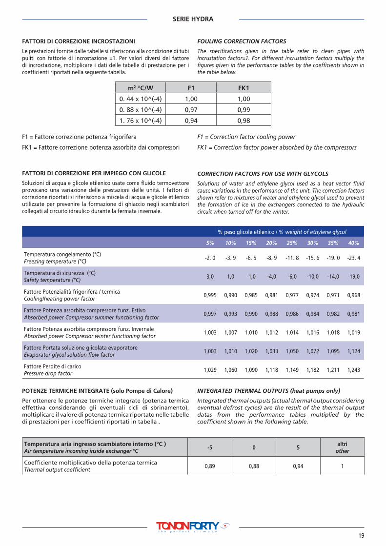
FATTORI DI CORREZIONE INCROSTAZIONI
Le prestazioni fornite dalle tabelle si riferiscono alla condizione di tubi puliti con fattorie di incrostazione =1. Per valori diversi del fattore di incrostazione, moltiplicare i dati delle tabelle di prestazione per i coefficienti riportati nella seguente tabella.
FOULING CORRECTION FACTORS
The specifications given in the table refer to clean pipes with incrustation factor=1. For different incrustation factors multiply the figures given in the performance tables by the coefficients shown in the table below.
FATTORI DI CORREZIONE PER IMPIEGO CON GLICOLE
Soluzioni di acqua e glicole etilenico usate come fluido termovettore provocano una variazione delle prestazioni delle unità. I fattori di correzione riportati si riferiscono a miscela di acqua e glicole etilenico utilizzate per prevenire la formazione di ghiaccio negli scambiatori collegati al circuito idraulico durante la fermata invernale.
CORRECTION FACTORS FOR USE WITH GLYCOLS
Solutions of water and ethylene glycol used as a heat vector fluid cause variations in the performance of the unit. The correction factors shown refer to mixtures of water and ethylene glycol used to prevent the formation of ice in the exchangers connected to the hydraulic circuit when turned off for the winter.
F1 = Fattore correzione potenza frigorifera
FK1 = Fattore correzione potenza assorbita dai compressori
F1 = Correction factor cooling power
FK1 = Correction factor power absorbed by the compressors
% peso glicole etilenico / % weight of ethylene glycol
5% 10% 15% 20% 25% 30% 35% 40%
Temperatura congelamento (°C)Freezing temperature (°C)
-2. 0 -3. 9 -6. 5 -8. 9 -11. 8 -15. 6 -19. 0 -23. 4
Temperatura di sicurezza (°C)Safety temperature (°C)
3,0 1,0 -1,0 -4,0 -6,0 -10,0 -14,0 -19,0
Fattore Potenzialità frigorifera / termicaCooling/heating power factor
0,995 0,990 0,985 0,981 0,977 0,974 0,971 0,968
Fattore Potenza assorbita compressore funz. EstivoAbsorbed power Compressor summer functioning factor
0,997 0,993 0,990 0,988 0,986 0,984 0,982 0,981
Fattore Potenza assorbita compressore funz. InvernaleAbsorbed power Compressor winter functioning factor
1,003 1,007 1,010 1,012 1,014 1,016 1,018 1,019
Fattore Portata soluzione glicolata evaporatore Evaporator glycol solution flow factor
1,003 1,010 1,020 1,033 1,050 1,072 1,095 1,124
Fattore Perdite di carico Pressure drop factor
1,029 1,060 1,090 1,118 1,149 1,182 1,211 1,243
POTENZE TERMICHE INTEGRATE (solo Pompe di Calore)
Per ottenere le potenze termiche integrate (potenza termica effettiva considerando gli eventuali cicli di sbrinamento), moltiplicare il valore di potenza termica riportato nelle tabelle di prestazioni per i coefficienti riportati in tabella .
INTEGRATED THERMAL OUTPUTS (heat pumps only)
Integrated thermal outputs (actual thermal output considering eventual defrost cycles) are the result of the thermal output datas from the performance tables multiplied by the coefficient shown in the following table.
Temperatura aria ingresso scambiatore interno (°C )Air temperature incoming inside exchanger °C
-5 0 5altri
other
Coefficiente moltiplicativo della potenza termicaThermal output coefficient
0,89 0,88 0,94 1

SERIE HYDRA
20
LIVELLI SONORI A PIENO CARICO UNITÀ HYDRA VERSIONE CHILLER
SOUND LEVEL SPECTRUM AT FULL LOAD RUNNING UNITS
Condizioni di funzionamentoAcqua impianto (in/out) 12/7 °C
Aria condensatore 35 °C
Pressione sonora a 1 metro: Si considera la pressione sonora rilevata in campo libero alla distanza di 1metro con sorgente di tipo emisferico
Pressione sonora a 10 metri: Si considera la pressione sonora rilevata in campo libero alla distanza di 10 metri con sorgente di tipo emisferico
Functioning conditionsSystem water (in/out) 12/7°C
Condenser air 35°C
Noise pressure level at 1 metre. The noise pressure level refers to a distance of 1m from a hemispheric type source in free field.
Noise pressure level at 1o metres. The noise pressure level refers to a distance of 10 m from a hemispheric type source in free field.
051 061 081 091 101 121 151Press. sonora unità Lp (dBA) ad 1m / Noise pressure unit Lp (dBa) at 1 m
63 Hz 30,8 30,8 32,4 32,0 32,0 32,1 34,8125 Hz 39,8 39,8 40,4 40,4 40,4 40,4 42,9250 Hz 51,0 51,0 54,8 54,8 54,8 54,9 54,5500 Hz 57,0 57,0 61,4 61,2 61,3 61,3 63,71000 Hz 59,3 59,4 64,0 63,6 63,6 63,7 65,62000 Hz 61,1 61,1 63,4 62,9 63,0 63,0 67,14000 Hz 55,4 55,5 59,7 59,4 59,4 59,4 62,78000 Hz 45,3 45,5 51,1 50,5 50,6 50,6 54,9Totale 65,0 65,0 68,7 68,4 68,4 68,5 71,3
Press. sonora unità Lp (dBA) a 10 m / Noise pressure unit Lp (dBa) at 10 m63 Hz 10,8 10,8 12,4 12,0 12,0 12,1 14,8125 Hz 19,8 19,8 20,4 20,4 20,4 20,4 22,9250 Hz 31,0 31,0 34,8 34,8 34,8 34,9 34,5500 Hz 37,0 37,0 41,4 41,2 41,3 41,3 43,71000 Hz 39,3 39,4 44,0 43,6 43,6 43,7 45,62000 Hz 41,1 41,1 43,4 42,9 43,0 43,0 47,14000 Hz 35,4 35,5 39,7 39,4 39,4 39,4 42,78000 Hz 25,3 25,5 31,1 30,5 30,6 30,6 34,9Totale 45,0 45,0 48,7 48,4 48,4 48,5 51,3
LIVELLI SONORI A PIENO CARICO UNITÀ HYDRA HT VERSIONE POMPE DI CALORE
SOUND LEVEL SPECTRUM AT FULL LOAD RUNNING UNITS
Condizioni di funzionamentoAcqua impianto (in/out) 39/45 °C
Aria scambiatore esterno 7 °C - UR 85%
Pressione sonora a 1 metro: Si considera la pressione sonora rilevata in campo libero alla distanza di 1metro con sorgente di tipo emisferico
Pressione sonora a 10 metri: Si considera la pressione sonora rilevata in campo libero alla distanza di 10 metri con sorgente di tipo emisferico
Functioning conditionsSystem water (in/out) 39/45°C
exchanger air outdoors 7°C - UR 85%
Noise pressure level at 1 metre. The noise pressure level refers to a distance of 1m from a hemispheric type source in free field.
Noise pressure level at 1o metres. The noise pressure level refers to a distance of 10 m from a hemispheric type source in free field.
051 061 081 091 101 121 151Press. sonora unità Lp (dBA) ad 1m / Noise pressure unit Lp (dBa) at 1 m
63 Hz 31,9 31,9 32,4 32,0 32,1 32,1 34,8125 Hz 40,4 40,4 40,4 40,4 40,4 40,4 42,9250 Hz 54,8 54,8 54,8 54,8 54,9 54,9 54,5500 Hz 61,1 61,1 61,4 61,2 61,3 61,4 63,71000 Hz 63,5 63,5 64,0 63,6 63,7 63,8 65,62000 Hz 62,7 62,7 63,4 62,9 63,1 63,3 67,14000 Hz 59,3 59,3 59,7 59,4 59,5 59,6 62,78000 Hz 50,3 50,3 51,1 50,5 50,8 50,9 54,9Totale 68,2 68,2 68,7 68,4 68,5 68,6 71,3
Press. sonora unità Lp (dBA) a 10 m / Noise pressure unit Lp (dBa) at 10 m63 Hz 11,9 11,9 12,4 12,0 12,1 12,1 14,8125 Hz 20,4 20,4 20,4 20,4 20,4 20,4 22,9250 Hz 34,8 34,8 34,8 34,8 34,9 34,9 34,5500 Hz 41,1 41,1 41,4 41,2 41,3 41,4 43,71000 Hz 43,5 43,5 44,0 43,6 43,7 43,8 45,62000 Hz 42,7 42,7 43,4 42,9 43,1 43,3 47,14000 Hz 39,3 39,3 39,7 39,4 39,5 39,6 42,78000 Hz 30,3 30,3 31,1 30,5 30,8 30,9 34,9Totale 48,2 48,2 48,7 48,4 48,5 48,6 51,3

SERIE HYDRA
21
DIMENSIONI - ATTACCHI - POSIZIONE ANTIVIBRANTI
MODELLI: HYDRA 051-061
DIMENSION - CONNECTIONS - ANTI VIBRATING MOUNTS POSITTION
MODEL: HYDRA 051-061
Ø1ingressoinlet
Ø2uscita (unità con pompa)outlet (unit with pump)
Ø3ingresso (unità senza pompa - optional)inlet (unit without pump - optional)
SPAZI POSIZIONAMENTOOPERATING SPACES
POSIZIONE ANTIVIBRANTIANTI VIBRATING MOUNTS POSITTION

SERIE HYDRA
22
DIMENSIONI - ATTACCHI - POSIZIONE ANTIVIBRANTI
MODELLI: HYDRA 081-091
DIMENSION - CONNECTIONS - ANTI VIBRATING MOUNTS POSITTION
MODEL: HYDRA 081-091
SPAZI POSIZIONAMENTOOPERATING SPACES
POSIZIONE ANTIVIBRANTIANTI VIBRATING MOUNTS POSITTION
Ø1ingressoinlet
Ø2uscita (unità con pompa)outlet (unit with pump)
Ø3ingresso (unità senza pompa - optional)inlet (unit without pump - optional)

SERIE HYDRA
23
DIMENSIONI - ATTACCHI - POSIZIONE ANTIVIBRANTI
MODELLI: HYDRA 101-121
DIMENSION - CONNECTIONS - ANTI VIBRATING MOUNTS POSITTION
MODEL: HYDRA 101-121
026
751
664
246
224
SPAZI POSIZIONAMENTOOPERATING SPACES
POSIZIONE ANTIVIBRANTIANTI VIBRATING MOUNTS POSITTION
Ø1ingressoinlet
Ø2uscita (unità con pompa)outlet (unit with pump)
Ø3ingresso (unità senza pompa - optional)inlet (unit without pump - optional)

SERIE HYDRA
24
DIMENSIONI - ATTACCHI - POSIZIONE ANTIVIBRANTI
MODELLI: HYDRA 151
DIMENSION - CONNECTIONS - ANTI VIBRATING MOUNTS POSITTION
MODEL: HYDRA 151
420
186
284
410
6011
522
SPAZI POSIZIONAMENTOOPERATING SPACES
POSIZIONE ANTIVIBRANTIANTI VIBRATING MOUNTS POSITTION
Ø1ingressoinlet
Ø2uscita (unità con pompa)outlet (unit with pump)
Ø3ingresso (unità senza pompa - optional)inlet (unit without pump - optional)

SERIE HYDRA
25
HY
DR
A 0
51/0
61H
YD
RA
081
/091
HY
DR
A 1
01/1
21H
YD
RA
151
ACCUMULI ACQUA INERZIALI (opzionali) BUFFER TANK (optional)


Qu
ader
no
tec
nic
o H
YD
RA
Co
d. 4
9887
2000
/200
8-it
/gb
rev
. 1.1