hydraulic capacity of cdot type c and d area … · 1 hydraulic capacity of cdot type c and d area...
TRANSCRIPT

1
HYDRAULIC CAPACITY of CDOT TYPE C and D AREA INLETS
(Installed in flat, depressed, and inclined configurations)
Prepared by James C.Y. Guo, PhD and PE
Submitted to Urban Drainage and Flood Control District,
Contract Agreement 10.07-04 Date: October 2011 (Draft)
Jan 25, 2012 (Revised) March 5, 2012 (Revised)
This report summarizes the theoretical derivation, laboratory data collection, modeling
calibration, and design application developed from the study on “Hydraulic Efficiency of
CDOT Type C and D inlets”. The major tasks in this project include: (1) laboratory tests
on Type C and D inlets using a1/3 scale model performed at the Hydraulic Laboratory,
Colorado State University, (2) development of design methods and calibration of design
procedures conducted at the University of Colorado Denver. Under the UDFCD
Agreement 10.07-04, this report presents the detailed derivation of governing equations
for determining the flow interception capacity through an inclined Type C or D inlet, and
calibration of flow coefficients used in the design equations.
TYPE C AND D INLETS
Type C and D inlets (TY C, TY D) are often installed at a low point for runoff collection
from a large depressed area or in a highway median. According to the Hydraulic Design
Manual issued by the Colorado Department of Transportation (CDOT), a TY C has a
standard frame size of 3-ft by 3-ft with I-beam bars to support the loadings on its top.
Figure 1 shows examples of TY C in a highway system.

2
Type C inlet in Highway Median Depressed Type C Inlet
Figure 1 Example Type C Inlet Installed in Colorado Highways
A TY D inlet is formed by two TY C inlets lined in series or in parallel with a standard
dimension of 3-ft by 6-ft. A TY C or D inlet is often located at the low point with a
headwater ranging from 0.5 to 3 feet to increase its flow interception capacity. A
depressed TY C or D inlet often entrains highway debris carried in the runoff flows. The
flow eddies and swirls circulate twigs and leaves between the I-beam bars. The
accumulated debris tends to clog the grate surface.
Laboratory Model for Inclined Type D Inlet Laboratory Model for Flat Type D Inlet
Figure 2 Illustration of Inclined and Flat Laboratory Type D Inlet Model
As illustrated in Figure 2, a TY D inlet laboratory model is installed with an inclined
angle facing the direction of inflow. It is expected that the floating debris will be pushed
3
up along the grate surface. While the debris is accumulated in the back of a TY D grate,
the front area on the grate surface remains open to intercept runoff flows.
HYDRAULIC CAPACITY AND FLOW INTERCEPTION
The capacity of at a TY C is quantified by its flow interception in terms of water volume
per time. The flow rate is an integration of the flow velocity acting on the finite flow area.
Although the flow continuity principle is derived using a vector approach, the integral of
flow interception through an opening area is stated as:
dAvCQ d (1)
Where Q= flow rate in L3/T, Cd= flow coefficient, v = flow velocity in L/T, and A= flow
area in L2. The flow velocity is calculated as:
ghv 2 (2)
Where g=gravitational acceleration, h = headwater depth on its flow area, dA, that will be
formulated according to flow direction and flow hydraulics.
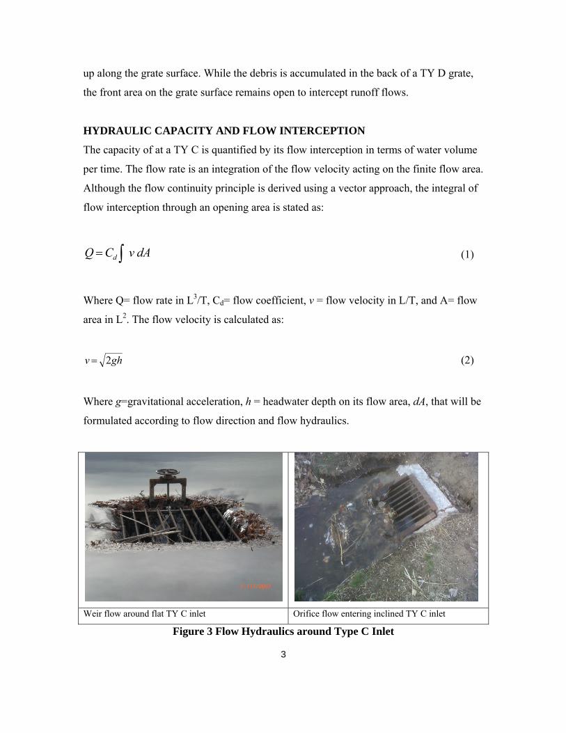
Weir flow around flat TY C inlet Orifice flow entering inclined TY C inlet
Figure 3 Flow Hydraulics around Type C Inlet

4
As shown in Figure 3, when the water depth is too shallow to submerge the entire inlet
grate, the grate operates like a weir. When the grate area is completely under water, the
inlet operates like an orifice.
WEIR FLOW CAPACITY
When the inclined grate operates like a weir, water overtops three submerged sides into
the inlet box, including two inclined sides and the lower base. As illustrated in Figure 4,
the TY C inlet is installed with an incline angle which is formed by the inlet length, L,
and box height, Hb. The coordination system is set to have h=0 at the water surface and
x=0 at the lower grate base. The headwater depth decreases along the grate from x=0 to
x=L which is the length of the grate.
Figure 4 Illustration of Side Weir Flow
When the water depth, H, is less than Hb, the infinitesimal flow area is derived as:
dA = (H – h) cot θ dh for H<Hb (3)
Where θ = inclined angle, dh = thickness of infinitesimal flow area, The weir flow, Qws,
overtopping the wetted length along the grate’s side is integrated as:
5
Hh
hd
Hh
hdWS dhhHhgnCdhhHghnCQ0
2/32/1
0)(cot2cot)(2 for H<Hb (4)
Where dq = flow over the infinitesimal area and n= net length ratio after subtracting
I-beam bar widths. Integration of Eq 4 yields:
2
5
215
4HCotgCnQ dWS for H<Hb (5)
When the grate is completely submerged as illustrated in Figure 4, the water depth,
H>Hb, is divided into two zones, i.e. above and below the top base of the grate as:
H=Hb +Ha (6)
Where H = water depth, Ha= surcharge depth above the top base of the grate as illustrated
in Figure 4, and Hb = vertical height of inclined grate above the ground. The infinitesimal
flow areas for these two zones are formulated as:
dA1 = (H – h) cot θ dh 0<h< Ha for Zone 1 (7)
dA2 =L cos θ dh Ha<h< H for Zone 2 (8)
The weir flow overtopping the wetted length is integrated as:
a
a
a
a
Hh
h
Hh
Hhdd
Hh
h
Hh
HhddWS dhhHghnCdhLghnCvdACvdACQ00 21 cot)(2cos2 (9)
Integrating Eq 9 yields:
)]5
2
3
2(
15
4[cot2cos2
3
2 2/35/22/3aadadWS HHHHgnCHLgnCQ
6
)(cot215
4
)]5
2
3
2(
15
4[cot2cos2
15
4
2/52/5
2/35/22/3
ad
aadadWS
HHgnC
HHHHgnCHLgnCQ
(10)
Re-arranging Eq 10 yields:
])(
[215
4])([2
15
4
3
2
2
5
3
2
2
5
2
3
2
5
2
5
b
b
b
bdbdWS
HH
HH
HH
HCotHHgnCHHHCotgnCQ
])(
[215
4
2
3
2
5
2
3
2
5
2
3
b
b
b
dWS
HH
HH
HH
HHCosLgnCQ
for H>Hb (11)
When H= Hb or the water surface just reaches the top of inclined grate, Eq (11) is
reduced to:
2
3
215
4bdWS HCosLgnCQ for H=Hb (12)
Eq 12 agrees with Eq 5 at H=Hb. It means that Eq’s 5 and 12 provide a continuous
function at H=Hb. The total flow, QWB, collected into the inlet is the sum of the weir
flows overtopping the two wetted sides along the grate and the lower base of the grate,
and. The weir flow, QWB, over the base is computed as:
2
3
23
2HBgnCQ dWB (13)
Where B= base width of grate. The total weir flow, QW, under a water depth of H above
the ground is the sum as:
WBWSW QQQ 2 (14)

7
ORIFICE FLOW CAPACITY
When the inclined grate operates like an orifice. The head water is applied to the opening
area on top of the grate. As illustrated in Figure 5, when H<Hb, the infinitesimal flow area
is defined as:
dA = n B dx cos θ = n B cosθ dx (15)
Figure 5 Illustration of Orifice Flow
in which n = opening area ratio on grate surface. Referring to Figure 5, the head water
depth, h, is related to the wetted length along the lower portion of the grate as:
HX
xh )1( (16)
where X= wetted length that varies between 0 X L, x= integration variable that varies
between 0≤x≤X. Substituting Eq 16 into Eq 2, the flow velocity acting on the flow area
is:

8
HX
xgghv )1(22 (H<Hb) (17)
For H Hb, the orifice flow, Qo, through the wetted surface area on the grate is calculated
as:
Xx
x dd
Xx
xdo gHXBnCdxX
xgHBnCvdAnCQ
002cos
3
212cos (18)
Re-arranging Eq 18 yields:
gHBHnCQ do 2cot3
2 for H Hb and θ≥0 (19)
When θ=0, X=L, cosθ=1, Eq 19 is reduced to a horizontal orifice as:
gHBLnCQ do 23
2 for H Hb and θ=0 (20)
When the grate is completely submerged, the flow depth is divided into two zones for
numerical integration as: (1) above the top of the grate and (2) below the top of the grate.
The headwater is expressed as
:
ba HL
xHHH
L
xHh )( (21)
Taking the first derivative of Eq 21 yields:
dxL
Hdh b (22)
The orifice flow through the wetted surface area on the grate is calculated as:

9
Lx
x bd
Lx
xdo dxL
xHHgBnCdxghBnCQ
002cos2cos (23)
Integration of Eq 23 yields:
(H>Hb) (24)
When H= Hb (the water surface just reaches the top of the inclined grate), Eq 24 is
reduced to:
(25)
Eq 19 and Eq 24 produce a continuous function at H=Hb.
DESIGN PROCEDURE
The opening ratio, n, is defined as the clear opening area on the grate surface as:
(26)
Where Clog = clogging factor 0 Clog 1.0, and Lb = cumulative width of I-beam bars on
grate. Eq 26 indicates that the area opening ratio is equal to the net length ratio on the
grate.
Figure 6 Net Opening Area on Type C Inlet
L
LLC
LB
BLLBCn bb
log)1(log)1(
])(
[2cos3
2 2
3
2
3
HH
HH
HH
HgHBLnCQ
b
b
b
do
gHBLnCQ do 2cos3
2

10
The governing equations derived in this report are dimensionally consistent when using
the flow coefficient, Cd. Table 1 is the summary of the derived equations under various
conditions.
Flow Type
Flow Overtopping Two Sides of Inclined Grate Flow overtopping the Lower Base Width
Condition
Orifice gHBXCosnCgHBHCotnCQ ddo 2
3
22
3
2
Subject to:
H<Hb Un-submerged
Weir subject to:
H<Hb Un-submerged
Orifice
In case of θ=0 and Hb=0, then
023
2 ifgHBLnCQ do
H Hb Submerged
Weir
])(
[215
4
2
3
2
5
2
3
2
5
2
3
b
b
b
dWS
HH
HH
HH
HHLCosgnCQ
In case of θ=0 and Hb=0, then
H Hb Submerged
Table 1 Equations derived for inclined inlet using flow coefficient, Cd.
Comparing with the conventional approach using orifice and weir hydraulics, the
equivalent orifice and weir coefficients are:
(27)
2
3
2
5
215
42
15
4HgXCosnCHCotgnCQ ddWS 2/32
3
2BHgnCQ dWB
2/323
2HBgnCQ dWB
WBWSW QQQ 2
WBWSW QQQ 2
LSin
HX
LSin
HX
2
3
23
2HgLnCQ dWS
])(
[23
2 2
3
2
3
HH
HH
HH
HgHBLCosnCQ
b
b
b
do
do CC3
2

11
(28)
Using Eq’s (27) and (28), Table 1 is converted to Table 2.
Flow Type
Flow Overtopping Two Sides of Inclined Grate Flow overtopping the Lower Base Width
Condition
Orifice gHBXCosnCgHBHCotnCQ ooo 22
Subject to:
H<Hb Un-submerged
Weir subject to:
H<Hb Un-submerged
Orifice
In case of θ=0 and Hb=0, then
02 ifgHBLnCQ oo
H Hb Submerged
Weir
])(
[2
3
2
5
2
3
2
5
2
3
b
b
b
wWS
HH
HH
HH
HHLCosnCQ
In case of θ=0 and Hb=0, then
H Hb Submerged
Table 2 Equations for inclined inlet using orifice coeff, Co, and weir coeff, Cw.
For a given water depth, the interception capacity, Qc , through an inclined grate is
dictated by weir or orifice flows, whichever is less as:
Qc= min (Qw, Qo) for a given water depth (29)
2
3
2
5
HXCosCnHCotCnQ wwWS 2/3BHnCQ wWB
2/3HBnCQ wWB
WBWSW QQQ 2
WBWSW QQQ 2
LSin
HX
LSin
HX
2
3
LHnCQ wWS
])(
[22
3
2
3
HH
HH
HH
HgHBLCosnCQ
b
b
b
oo
gCC dw 215
4
12
On the contrary, for a given design flow, the required headwater depth, H, acting on an
inclined grate is determined as:
H= max (Hw, Ho) for a given design flow (30)
Where Hw = headwater for weir flow, Ho= headwater for orifice flow, and H= design
headwater.
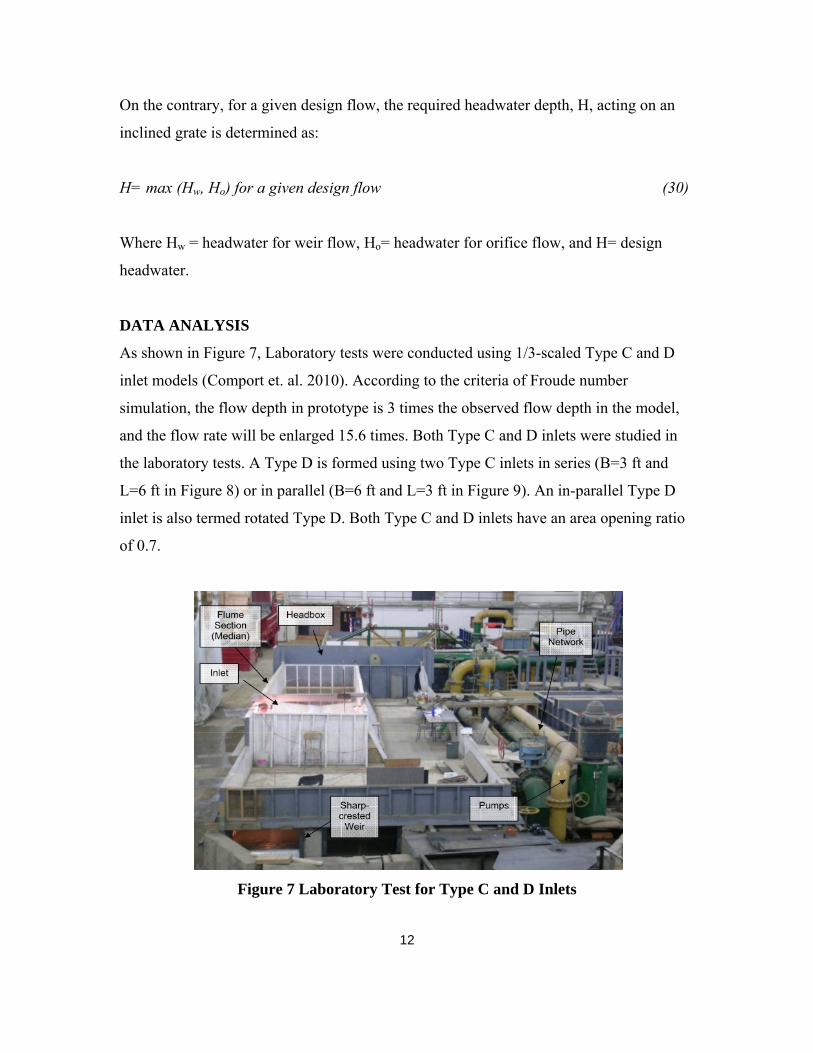
DATA ANALYSIS
As shown in Figure 7, Laboratory tests were conducted using 1/3-scaled Type C and D
inlet models (Comport et. al. 2010). According to the criteria of Froude number
simulation, the flow depth in prototype is 3 times the observed flow depth in the model,
and the flow rate will be enlarged 15.6 times. Both Type C and D inlets were studied in
the laboratory tests. A Type D is formed using two Type C inlets in series (B=3 ft and
L=6 ft in Figure 8) or in parallel (B=6 ft and L=3 ft in Figure 9). An in-parallel Type D
inlet is also termed rotated Type D. Both Type C and D inlets have an area opening ratio
of 0.7.
Figure 7 Laboratory Test for Type C and D Inlets

13
The inclined angles for this study vary from 0 to 30-degree. The model inlet was placed
under a condition with or without a depression of one foot. As summarized in Appendix
I, II, and III, there were 96 data sets measured at the Hydraulic Laboratory at the
Colorado State University (Comport 2010). Each set of data includes flow intercepted by
the model inlet and flow depth applied to the front of the model inlet. The values of flow
coefficient, Cd, are derived using the least error- square method between the predicted
and observed flow rates under the observed flow depths. Appendix IV presents several
sample analyses of the depth-flow relationships reported from the laboratory data.
Figure 8 Type D Model formed with two Type C Inlets in Series

14
Figure 9 Rotated Type D Model formed with two Type C Inlets in Parallel
Figures 10 through 12 and Tables 3 through 5 present the flow coefficients for the
governing equations derived in this report.
15
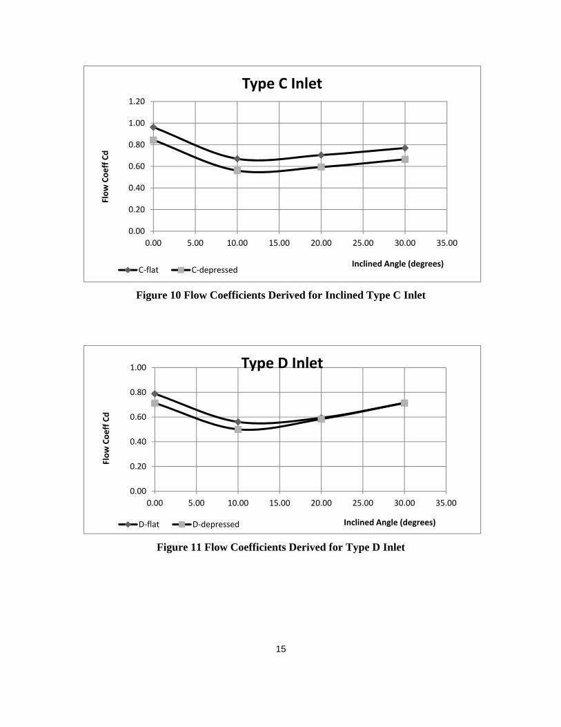
Figure 10 Flow Coefficients Derived for Inclined Type C Inlet
Figure 11 Flow Coefficients Derived for Type D Inlet
0.00
0.20
0.40
0.60
0.80
1.00
1.20
0.00 5.00 10.00 15.00 20.00 25.00 30.00 35.00
Flow Coeff Cd
Inclined Angle (degrees)
Type C Inlet
C‐flat C‐depressed
0.00
0.20
0.40
0.60
0.80
1.00
0.00 5.00 10.00 15.00 20.00 25.00 30.00 35.00
Flow Coeff Cd
Inclined Angle (degrees)
Type D Inlet
D‐flat D‐depressed

16
Figure 12 Flow Coefficients Derived for Rotated Type D Inlet
Type of Inlet Inclined Angle (degrees) Remark
Condition 0.00 10.00 20.00 30.00
C‐flat 0.96 0.67 0.70 0.77
C‐depressed 0.84 0.56 0.59 0.67 1‐ft depression
D‐flat 0.79 0.56 0.59 0.71
D‐depressed 0.71 0.50 0.58 0.71 1‐ft depression
D‐rotated 0.74 0.60 0.60 0.74
D‐rotated‐depressed 0.61 0.51 0.51 0.74 1‐ft depression
Table 3 Flow Coefficients
Type of Inlet Inclined Angle (degrees) Remark
Condition 0.00 10.00 20.00 30.00
C‐flat 0.64 0.45 0.47 0.51
C‐depressed 0.56 0.37 0.40 0.44 1‐ft depression
D‐flat 0.53 0.37 0.40 0.48
D‐depressed 0.48 0.33 0.39 0.48 1‐ft depression
D‐rotated 0.49 0.40 0.40 0.49
D‐rotated‐depressed 0.41 0.34 0.34 0.49 1‐ft depression
Table 4 Equivalent Orifice Coefficients
0.00
0.10
0.20
0.30
0.40
0.50
0.60
0.70
0.80
0.00 5.00 10.00 15.00 20.00 25.00 30.00 35.00
Flow Coeff Cd
Inclined Angle (degrees)
Type D Inlet‐Rotated
D‐rot‐flat D‐rot‐depressed

17
Type of Inlet Inclined Angle (degrees) Remark
Condition 0.00 10.00 20.00 30.00
C‐flat 2.06 1.43 1.51 1.65
C‐depressed 1.80 1.20 1.27 1.42 1‐ft depression
D‐flat 1.69 1.20 1.27 1.53
D‐depressed 1.53 1.07 1.25 1.53 1‐ft depression
D‐rotated 1.58 1.28 1.28 1.58
D‐rotated‐depressed 1.31 1.08 1.09 1.58 1‐ft depression
Table 5 Equivalent Weir Coefficients for English Units
Type of Inlet Inclined Angle (degrees) Remark
Condition 0.00 10.00 20.00 30.00
C‐flat 1.14 0.79 0.83 0.91
C‐depressed 1.00 0.66 0.70 0.79 1‐ft depression
D‐flat 0.93 0.66 0.70 0.84
D‐depressed 0.84 0.59 0.69 0.84 1‐ft depression
D‐rotated 0.87 0.71 0.71 0.87
D‐rotated‐depressed 0.72 0.60 0.60 0.87 1‐ft depression
Table 6 Equivalent Weir Coefficients for Metric Units
CLOGGING EFFECT
Type C and Type D inlets are susceptible to debris clogging. To be conservative, a
clogging factor of 0.5 is recommended for a Type C inlet (Guo 2000C). For a Type D
inlet, the decay-based clogging is recommended (Guo 2006). Namely, the first grate is
subject to a clogging factor of 0.5 and the second grate may have a clogging potential of
0.25. Or, an average clogging factor of 0.375 is applicable to two grates, i.e. a Type D
inlet.

18
Clogged Type D Inlet Accumulation of Debris around Ty D inlet
Figure 13 Clogging Condition around Type D Inlet in Field
CONCLUSION
Tables 1 and 2 summarize the new formulas developed to design Type C and D inlets for
highway median drainage systems. The inclined angle can be raised from 0 to 30 degrees
for debris control. When the inlet is laid flat on the ground, the equations in Tables 1 and
2 are reduced to the conventional equations recommended for a horizontal inlet.
Tables 3 through 6 present the best-fitted values for flow coefficient, Cd, orifice
coefficient, Co, and weir coefficient, Cw, derived from 92 sets of laboratory data.
Although the flow coefficient used in the new equations in Table 1 is dimensionless,
workable with both English and Metric units, it can be converted into the conventional
orifice and weir flow coefficients in Table 2. Care needs to be taken because the value of
weir coefficient is unit dependent.
In comparison, a flat Type C inlet has the highest flow interception capacity compared to
the inclined. To compensate the clogging effect, an inclined angle is recommended. The
laboratory data indicate that there is a tradeoff between the reduction on clogging
coefficient and the decrease in flow interception. With the recommended flow
19
coefficients, the engineer can select the design parameters based on the optimal
performance of the inlet under the specified condition in the field.
REFERENCES
AASHTO (2007). ” Highway Drainage Guidelines, 4th Edition. CDOT (2004) “Drainage Design Manual”, Colorado of Department of Transportation, Denver, Colorado. Comport, B.C., Cox, A. L., and Thornton C. (2010). “Performance Assessment of Grate Inlets for Highway Median Drainage”, submitted to UDFCD, Denver, Colorado. Guo, James C.Y. and McKenzie, K, and Mommandi, A. (2008) “Sump Inlet Hydraulics”, ASCE J. of Hydraulic Engineering, Vol 135, No 1, Nov.
Guo, James C.Y. (2000A). “Street Storm Water Conveyance Capacity,” ASCE J. of Irrigation and Drainage Engineering, Vol 126, No 2, Mar/Apr,
Guo, James C.Y. (2000B). “Street Storm Water Storage Capacity”, J. of Water Environment Research, Vol 27, No 6., Sept./Oct.
Guo, James C.Y. (2006). “Decay-based Clogging Factor for Curb Inlet Design”, Vol 132, No. 11, ASCE J. of Hydraulic Engineering, November.
Guo, James C.Y. (2000C). “Design of Grate Inlets with a Clogging Factor,” Advances in Environmental Research, Vol 4, Elsvier Science, Ireland.
Guo, James C.Y. (1999). “Street Hydraulics and Inlet Sizing”, published by WRP Company, Littleton, Colorado.
HEC 12, (1984). "Drainage of Highway Pavements", US Department of Transportation, Federal Highway Administration Washington D.C., Virginia. HEC 22 (2002) "Urban Drainage Design Manual , US Department of Transportation, Federal Highway Administration, Washington D.C., Virginia. Huebner, R.S., Reed, J.R., and Henry, J.J., (1986) "Criteria for Predicting Hydroplaning Potential," ASCE Journal of Transportation Engineering, Vol 12, No 5, September.
Mays, L (2001) “Stormwater Collection Systems Design Handbook”, published by McGraw Hill Publication Company in August.
McEnroe, M.B., Wade, P. R. and Smith, A.K. (1999). “Hydraulic Performance of Curb and Gutter Inlets”, Report No. K-TRAN: KU-99-1, Kansas Department of Transportation, September.

20
USWDCM (2001) "Storm Water Design Criteria Manual," Vol 1 and 2, Urban Drainage and Flood Control District, Denver, Colorado

21
Appendix 1 Laboratory Data for Type C Inlet
Laboratory Observation
Test ConfigurationGrate angle (deg)
Inlet Depth
(ft)
Flow measured
(cfs)
Prototype Inlet Depth
(ft)
Prototype flow (cfs)
1 C 0 0.352 1.84 1.06 28.7
2 C 0 0.513 2.46 1.54 38.3
3 C 0 0.795 3.39 2.39 52.8
4 C 0 1.037 3.75 3.11 58.4
6 C 10 0.370 1.85 1.11 28.8
7 C 10 0.528 2.46 1.58 38.3
8 C 10 0.765 3.14 2.30 48.9
9 C 10 1.044 3.62 3.13 56.4
11 C 20 0.369 1.72 1.11 26.8
12 C 20 0.506 2.24 1.52 34.9
13 C 20 0.798 2.98 2.39 46.4
14 C 20 0.989 3.41 2.97 53.1
16 C 30 0.362 1.53 1.09 23.8
17 C 30 0.516 2.24 1.55 34.9
18 C 30 0.748 2.86 2.24 44.6
19 C 30 1.008 3.50 3.02 54.5
21 C depressed 0 0.668 1.95 2.00 30.4
22 C depressed 0 0.834 2.43 2.50 37.9
23 C depressed 0 1.089 3.60 3.27 56.1
24 C depressed 0 1.365 4.23 4.10 65.9
26 C depressed 10 0.707 1.87 2.12 29.1
27 C depressed 10 0.864 2.50 2.59 39.0
28 C depressed 10 1.118 3.43 3.35 53.4
29 C depressed 10 1.341 4.04 4.02 62.9
31 C depressed 20 0.639 2.35 1.92 36.6
32 C depressed 20 0.840 2.42 2.52 37.7
33 C depressed 20 1.098 3.25 3.29 50.6
34 C depressed 20 1.337 3.89 4.01 60.6
36 C depressed 30 0.685 2.55 2.06 39.7
37 C depressed 30 0.825 2.84 2.48 44.2
38 C depressed 30 1.078 3.25 3.23 50.6
39 C depressed 30 1.345 3.99 4.04 62.2
22
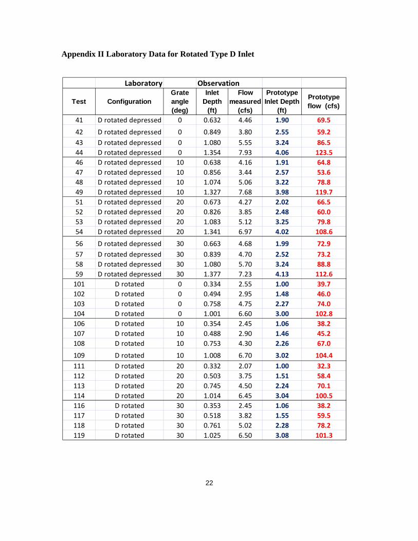
Appendix II Laboratory Data for Rotated Type D Inlet
Laboratory Observation
Test ConfigurationGrate angle (deg)
Inlet Depth
(ft)
Flow measured
(cfs)
Prototype Inlet Depth
(ft)
Prototype flow (cfs)
41 D rotated depressed 0 0.632 4.46 1.90 69.5
42 D rotated depressed 0 0.849 3.80 2.55 59.2
43 D rotated depressed 0 1.080 5.55 3.24 86.5
44 D rotated depressed 0 1.354 7.93 4.06 123.5
46 D rotated depressed 10 0.638 4.16 1.91 64.8
47 D rotated depressed 10 0.856 3.44 2.57 53.6
48 D rotated depressed 10 1.074 5.06 3.22 78.8
49 D rotated depressed 10 1.327 7.68 3.98 119.7
51 D rotated depressed 20 0.673 4.27 2.02 66.5
52 D rotated depressed 20 0.826 3.85 2.48 60.0
53 D rotated depressed 20 1.083 5.12 3.25 79.8
54 D rotated depressed 20 1.341 6.97 4.02 108.6
56 D rotated depressed 30 0.663 4.68 1.99 72.9
57 D rotated depressed 30 0.839 4.70 2.52 73.2
58 D rotated depressed 30 1.080 5.70 3.24 88.8
59 D rotated depressed 30 1.377 7.23 4.13 112.6
101 D rotated 0 0.334 2.55 1.00 39.7
102 D rotated 0 0.494 2.95 1.48 46.0
103 D rotated 0 0.758 4.75 2.27 74.0
104 D rotated 0 1.001 6.60 3.00 102.8
106 D rotated 10 0.354 2.45 1.06 38.2
107 D rotated 10 0.488 2.90 1.46 45.2
108 D rotated 10 0.753 4.30 2.26 67.0
109 D rotated 10 1.008 6.70 3.02 104.4
111 D rotated 20 0.332 2.07 1.00 32.3
112 D rotated 20 0.503 3.75 1.51 58.4
113 D rotated 20 0.745 4.50 2.24 70.1
114 D rotated 20 1.014 6.45 3.04 100.5
116 D rotated 30 0.353 2.45 1.06 38.2
117 D rotated 30 0.518 3.82 1.55 59.5
118 D rotated 30 0.761 5.02 2.28 78.2
119 D rotated 30 1.025 6.50 3.08 101.3

23
Appendix III Laboratory Data for Type D Inlet
Laboratory Observation
Test ConfigurationGrate angle (deg)
Inlet Depth
(ft)
Flow measured
(cfs)
Prototype Inlet Depth
(ft)
Prototype flow (cfs)
61 D depressed 0 0.657 4.06 1.97 63.3
62 D depressed 0 0.979 4.45 2.94 69.3
63 D depressed 0 1.075 5.11 3.23 79.6
64 D depressed 0 1.345 7.55 4.04 117.6
66 D depressed 10 0.660 3.87 1.98 60.3
67 D depressed 10 0.932 4.13 2.80 64.3
68 D depressed 10 1.094 5.32 3.28 82.9
69 D depressed 10 1.336 6.95 4.01 108.3
71 D depressed 20 0.673 3.54 2.02 55.2
72 D depressed 20 0.846 4.35 2.54 67.8
73 D depressed 20 1.085 5.36 3.26 83.5
74 D depressed 20 1.326 6.65 3.98 103.6
76 D depressed 30 0.674 3.24 2.02 50.5
77 D depressed 30 0.844 4.62 2.53 72.0
78 D depressed 30 1.101 5.55 3.30 86.5
79 D depressed 30 1.332 6.79 4.00 105.8
81 D 0 0.323 2.24 0.97 34.9
82 D 0 0.509 3.39 1.53 52.8
83 D 0 0.749 5.20 2.25 81.0
84 D 0 1.005 6.63 3.02 103.3
86 D 10 0.366 2.00 1.10 31.2
87 D 10 0.513 3.43 1.54 53.4
88 D 10 0.770 4.88 2.31 76.0
89 D 10 1.015 6.15 3.05 95.8
91 D 20 0.335 1.11 1.01 17.3
92 D 20 0.504 2.27 1.51 35.4
93 D 20 0.758 4.20 2.27 65.4
94 D 20 1.001 5.60 3.00 87.2
96 D 30 0.358 1.29 1.07 20.1
97 D 30 0.528 2.19 1.58 34.1
98 D 30 0.780 3.52 2.34 54.8
99 D 30 1.022 4.99 3.07 77.7

24
Appendix IV Sample Analyses for Flow Coefficients
Width of Grate B 3.00 (input)
Inclined Length of Grate L 3.00 ft
Opening Ratio of Grate n 0.70 (input)
Grate Discharge Coeff Cd 0.96 (input)
Height of Box Hb= 0.00 ft
Inclined Angle @ 0.00 degree (input)
Orifice/ Weir Coeff Co= 0.64 Cw= 2.06
Orientation Ko= 0
Water Submerged Side Inclined Inclined Base Total Total Predcited Observed Error Sq error
Depth H Weir Length Left S Weir Right S Weir Weir Weir Orifice Flow Flow
ft ft (X) cfs cfs cfs cfs cfs cfs cfs % cfs 2̂
1.06 3.00 11.73 11.73 16.76 40.21 33.32 33.32 28.7 -16.23% 21.66
1.54 3.00 20.64 20.64 29.48 70.75 40.23 40.23 38.3 -4.96% 3.61
2.39 3.00 39.81 39.81 56.87 136.49 50.08 50.08 52.8 5.19% 7.51
3.11 3.00 59.31 59.31 84.73 203.34 57.19 57.19 58.4 2.11% 1.52
34.29
0.00
0.50
1.00
1.50
2.00
2.50
3.00
3.50
0.00 20.00 40.00 60.00 80.00
Flow Depth in
feet
Flowrate in cfs
0‐degree Inclined Ty C Inlet
predicted measured

25
Width of Grate B 3.00 (input)
Inclined Length of Grate L 3.00 ft
Opening Ratio of Grate n 0.70 (input)
Grate Discharge Coeff Cd 0.77 (input)
Height of Box Hb= 1.50 ft
Inclined Angle @ 30.00 degree (input)
Orifice/ Weir Coeff Co= 0.51 Cw= 1.65
Orientation Ko= 0
Water Submerged Side Inclined Inclined Base Total Total Predcited Observed Error Sq error
Depth H Weir Length Left S Weir Right S Weir Weir Weir Orifice Flow Flow
ft ft (X) cfs cfs cfs cfs cfs cfs cfs % cfs 2̂
1.09 2.17 2.46 2.46 9.79 14.70 19.58 14.70 23.8 38.33% 83.46
1.55 3.00 5.96 5.96 16.66 28.57 33.14 28.57 34.9 18.13% 40.03
2.24 3.00 14.12 14.12 29.08 57.31 47.06 47.06 44.6 -5.60% 6.23
3.02 3.00 26.04 26.04 45.49 97.58 58.43 58.43 54.5 -7.15% 15.21
144.93
0.00
0.50
1.00
1.50
2.00
2.50
3.00
3.50
0.00 20.00 40.00 60.00 80.00
Flow Depth in
feet
Flowrate in cfs
30‐degree Inclined Ty C Inlet
predicted measured

26
Width of Grate B 3.00 (input)
Inclined Length of Grate L 3.00 ft
Opening Ratio of Grate n 0.70 (input)
Grate Discharge Coeff Cd 0.84 (input)
Height of Box Hb= 0.00 ft
Inclined Angle @ 0.00 degree (input)
Orifice/ Weir Coeff Co= 0.56 Cw= 1.80
Orientation Ko= 0
Water Submerged Side Inclined Inclined Base Total Total Predcited Observed Error Sq error
Depth H Weir Length Left S Weir Right S Weir Weir Weir Orifice Flow Flow
ft ft (X) cfs cfs cfs cfs cfs cfs cfs % cfs 2̂
2.00 3.00 26.88 26.88 26.88 80.65 40.24 40.24 30.4 -32.47% 97.28
2.50 3.00 37.50 37.50 37.50 112.51 44.97 44.97 37.9 -18.77% 50.52
3.27 3.00 55.96 55.96 55.96 167.87 51.38 51.38 56.1 8.39% 22.13
4.10 3.00 78.53 78.53 78.53 235.58 57.53 57.53 65.9 12.71% 70.14
240.08
0.000.501.001.502.002.503.003.504.004.50
0.00 20.00 40.00 60.00 80.00
Flow Depth in
feet
Flowrate in cfs
0‐degree Inclined and Depressed Ty C Inlet
predicted measured
27
Width of Grate B 3.00 (input)
Inclined Length of Grate L 3.00 ft
Opening Ratio of Grate n 0.70 (input)
Grate Flow Coeff Cd 0.67 (input)
Height of Box Hb= 1.50 ft
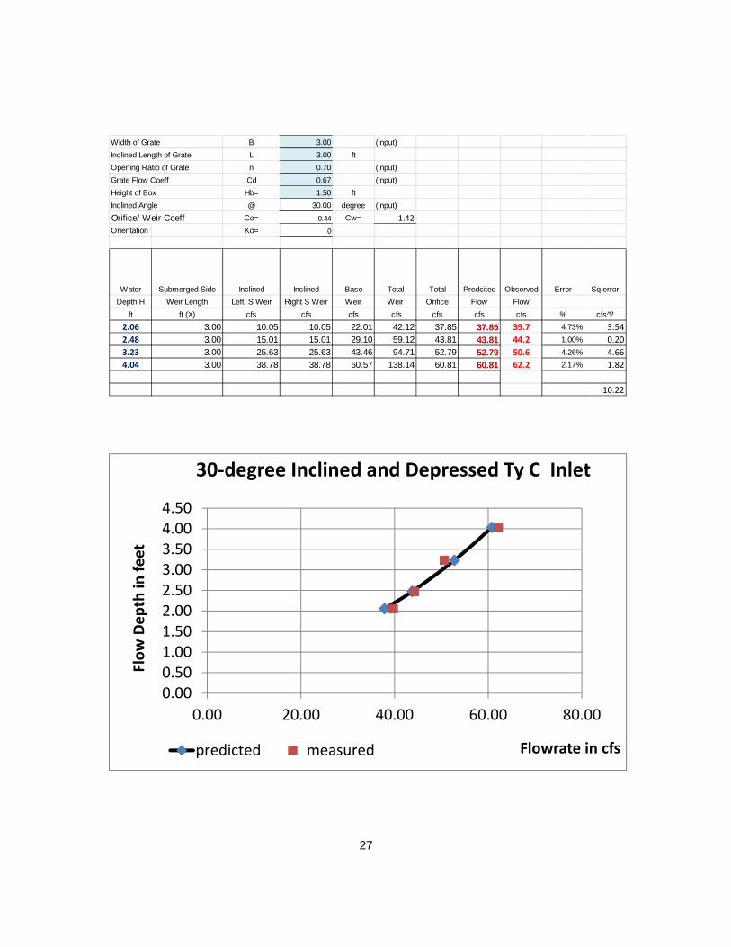
Inclined Angle @ 30.00 degree (input)
Orifice/ Weir Coeff Co= 0.44 Cw= 1.42
Orientation Ko= 0
Water Submerged Side Inclined Inclined Base Total Total Predcited Observed Error Sq error
Depth H Weir Length Left S Weir Right S Weir Weir Weir Orifice Flow Flow
ft ft (X) cfs cfs cfs cfs cfs cfs cfs % cfs 2̂
2.06 3.00 10.05 10.05 22.01 42.12 37.85 37.85 39.7 4.73% 3.54
2.48 3.00 15.01 15.01 29.10 59.12 43.81 43.81 44.2 1.00% 0.20
3.23 3.00 25.63 25.63 43.46 94.71 52.79 52.79 50.6 -4.26% 4.66
4.04 3.00 38.78 38.78 60.57 138.14 60.81 60.81 62.2 2.17% 1.82
10.22
0.000.501.001.502.002.503.003.504.004.50
0.00 20.00 40.00 60.00 80.00
Flow Depth in
feet
Flowrate in cfs
30‐degree Inclined and Depressed Ty C Inlet
predicted measured
28
Width of Grate B 3.00 (input)
Inclined Length of Grate L 6.00 ft
Opening Ratio of Grate n 0.70 (input)
Grate Discharge Coeff Cd 0.76 (input)
Height of Box Hb= 0.00 ft
Inclined Angle @ 0.00 degree (input)
Orifice/ Weir Coeff Co= 0.50 Cw= 1.62
Orientation Ko= 0
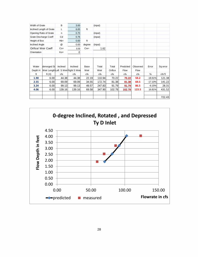
Water ubmerged Sid Inclined Inclined Base Total Total Predcited Observed Error Sq error
Depth H Weir LengthLeft S WeirRight S Weir Weir Weir Orifice Flow Flow
ft ft (X) cfs cfs cfs cfs cfs cfs cfs % cfs 2̂
1.90 6.00 44.38 44.38 22.19 110.94 70.22 70.22 59.2 -18.61% 121.38
2.55 6.00 69.09 69.09 34.55 172.74 81.38 81.38 69.5 -17.10% 141.22
3.24 6.00 99.13 99.13 49.57 247.83 91.79 91.79 86.5 -6.15% 28.31
4.06 6.00 139.16 139.16 69.58 347.90 102.78 102.78 123.5 16.81% 431.52
722.43
0.00
0.50
1.00
1.50
2.00
2.50
3.00
3.50
4.00
4.50
0.00 50.00 100.00 150.00
Flow Depth in
feet
Flowrate in cfs
0‐degree Inclined, Rotated , and Depressed Ty D Inlet
predicted measured

29
Width of Grate B 6.00 (input)
Inclined Length of Grate L 3.00 ft
Opening Ratio of Grate n 0.70 (input)
Grate Discharge Coeff Cd 0.60 (input)
Height of Box Hb= 1.50 ft
Inclined Angle @ 30.00 degree (input)
Orifice/ Weir Coeff Co= 0.40 Cw= 1.28
Orientation Ko= 0
Water Submerged Side Inclined Inclined Base Total Total Predcited Observed Error Sq error
Depth H Weir Length Left S Weir Right S Weir Weir Weir Orifice Flow Flow
ft ft (X) cfs cfs cfs cfs cfs cfs cfs % cfs 2̂
1.99 3.00 8.42 8.42 37.78 54.62 66.35 54.62 72.9 25.09% 334.79
2.52 3.00 14.01 14.01 53.79 81.80 79.94 79.94 73.2 -9.17% 45.08
3.24 3.00 23.18 23.18 78.55 124.90 95.27 95.27 88.8 -7.28% 41.81
4.13 3.00 36.48 36.48 113.09 186.05 111.21 111.21 112.6 1.27% 2.04
423.72
0.000.501.001.502.002.503.003.504.004.50
0.00 50.00 100.00 150.00
Flow Depth in
feet
Flowrate in cfs
30‐degree Inclined, Rotated, and Depressed Ty D Inlet
predicted measured

30
Width of Grate B 3.00 (input)
Inclined Length of Grate L 6.00 ft
Opening Ratio of Grate n 0.70 (input)
Grate Discharge Coeff Cd 0.79 (input)
Height of Box Hb= 0.00 ft
Inclined Angle @ 0.00 degree (input)
Orifice/ Weir Coeff Co= 0.53 Cw= 1.69
Orientation Ko= 0
Water ubmerged Sid Inclined Inclined Base Total Total Predcited Observed Error Sq error
Depth H Weir LengthLeft S Weir Right S Weir Weir Weir Orifice Flow Flow
ft ft (X) cfs cfs cfs cfs cfs cfs cfs % cfs 2̂
0.97 6.00 16.89 16.89 8.44 42.22 52.28 42.22 34.9 -20.97% 53.58
1.53 6.00 33.41 33.41 16.70 83.52 65.63 65.63 52.8 -24.27% 164.26
2.25 6.00 59.63 59.63 29.82 149.08 79.62 79.62 81.0 1.73% 1.96
3.02 6.00 92.69 92.69 46.34 231.71 92.22 92.22 103.3 10.72% 122.57
342.37
0.00
0.50
1.00
1.50
2.00
2.50
3.00
3.50
0.00 50.00 100.00 150.00
Flow Depth in
feet
Flowrate in cfs
0‐degree Inclined Ty D Inlet
predicted measured

31
Width of Grate B 3.00 (input)
Inclined Length of Grate L 6.00 ft
Opening Ratio of Grate n 0.70 (input)
Grate Flow Coeff Cd 0.68 (input)
Height of Box Hb= 3.00 ft
Inclined Angle @ 30.00 degree (input)
Orifice/ Weir Coeff Co= 0.45 Cw= 1.45
Orientation Ko= 0
Water Submerged Side Inclined Inclined Base Total Total Predcited Observed Error Sq error
Depth H Weir Length Left S Weir Right S Weir Weir Weir Orifice Flow Flow
ft ft (X) cfs cfs cfs cfs cfs cfs cfs % cfs 2̂
1.07 2.15 2.10 2.10 8.47 12.67 16.94 12.67 20.1 36.95% 55.15
1.58 3.17 5.55 5.55 15.17 26.27 30.34 26.27 34.1 23.00% 61.60
2.34 4.68 14.72 14.72 27.24 56.68 54.48 54.48 54.8 0.66% 0.13
3.07 6.00 28.93 28.93 40.86 98.71 81.45 81.45 77.7 -4.77% 13.74
130.62
0.00
0.50
1.00
1.50
2.00
2.50
3.00
3.50
0.00 20.00 40.00 60.00 80.00 100.00
Flow Depth in
feet
Flowrate in cfs
30‐degree Inclined Ty D Inlet
predicted measured