hydraulic climbing platforms - mesaimalat.com.tr · are in accordance with din and fem (rules for...
TRANSCRIPT
06/2010 Technical Manual
MESA - HCP Hydraulic Climbing Platforms

Contents Remarks General Remarks 1 Safety Remarks 2 Warranty 3 Introduction System Description 4 Working Limits 5 Scope of Applications 6 System Overview 10 Parts 12 Basic Information Technical Info 16 Platform Levels 18 Assembly Preperation of Concrete 19 Assembly of the Main&Lower Platforms 22 Assembly of the Upper Platform 27 Assembly of Formworks 29 Finishing the Assembly 31 Maintenance Maintenance 34
Remarks General Remarks
Hydraulic Climbing Platform – HCP 1
TECHNICAL MANUAL – 06/2010 www.mesaimalat.com.tr
GENERAL REMARKS
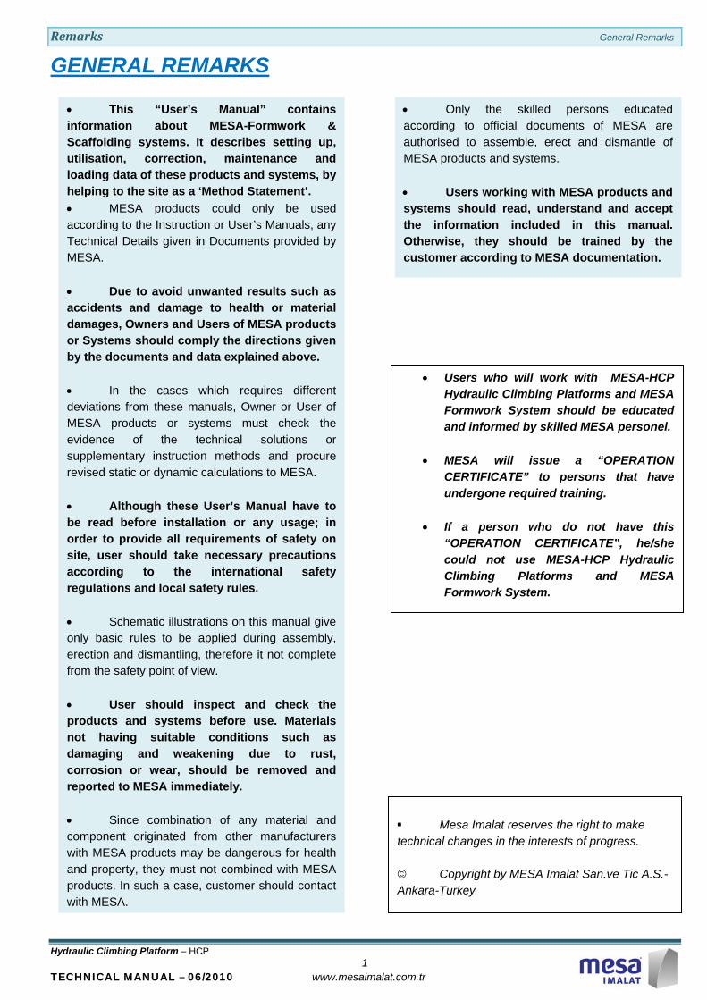
• This “User’s Manual” contains information about MESA-Formwork & Scaffolding systems. It describes setting up, utilisation, correction, maintenance and loading data of these products and systems, by helping to the site as a ‘Method Statement’. • MESA products could only be used according to the Instruction or User’s Manuals, any Technical Details given in Documents provided by MESA. • Due to avoid unwanted results such as accidents and damage to health or material damages, Owners and Users of MESA products or Systems should comply the directions given by the documents and data explained above. • In the cases which requires different deviations from these manuals, Owner or User of MESA products or systems must check the evidence of the technical solutions or supplementary instruction methods and procure revised static or dynamic calculations to MESA. • Although these User’s Manual have to be read before installation or any usage; in order to provide all requirements of safety on site, user should take necessary precautions according to the international safety regulations and local safety rules. • Schematic illustrations on this manual give only basic rules to be applied during assembly, erection and dismantling, therefore it not complete from the safety point of view. • User should inspect and check the products and systems before use. Materials not having suitable conditions such as damaging and weakening due to rust, corrosion or wear, should be removed and reported to MESA immediately. • Since combination of any material and component originated from other manufacturers with MESA products may be dangerous for health and property, they must not combined with MESA products. In such a case, customer should contact with MESA.
• Only the skilled persons educated according to official documents of MESA are authorised to assemble, erect and dismantle of MESA products and systems. • Users working with MESA products and systems should read, understand and accept the information included in this manual. Otherwise, they should be trained by the customer according to MESA documentation.
• Users who will work with MESA-HCP Hydraulic Climbing Platforms and MESA Formwork System should be educated and informed by skilled MESA personel.
• MESA will issue a “OPERATION CERTIFICATE” to persons that have undergone required training.
• If a person who do not have this “OPERATION CERTIFICATE”, he/she could not use MESA-HCP Hydraulic Climbing Platforms and MESA Formwork System.
Mesa Imalat reserves the right to make technical changes in the interests of progress.
© Copyright by MESA Imalat San.ve Tic A.S.-Ankara-Turkey
Remarks Safety Remarks
Hydraulic Climbing Platform – HCP 2
TECHNICAL MANUAL – 06/2010 www.mesaimalat.com.tr
SAFETY REMARKS
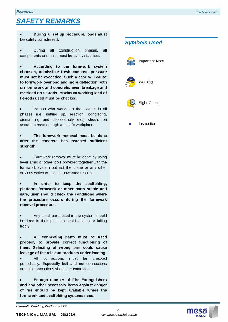
Symbols Used
Important Note
Warning
Sight-Check
Instruction
• During all set up procedure, loads must be safely transferred. • During all construction phases, all components and units must be safely stabilised. • According to the formwork system choosen, admissible fresh concrete pressure must not be exceeded. Such a case will cause to formwork overload and more deflection both on formwork and concrete, even breakage and overload on tie-rods. Maximum working load of tie-rods used must be checked. • Person who works on the system in all phases (i.e. setting up, erection, concreting, dismantling and disassembly etc.) should be assure to have enough and safe workplace. • The formwork removal must be done after the concrete has reached sufficient strength. • Formwork removal must be done by using lever arms or other tools provided together with the formwork system but not the crane or any other devices which will cause unwanted results. • In order to keep the scaffolding, platform, formwork or other parts stable and safe, user should check the conditions where the procedure occurs during the formwork removal procedure. • Any small parts used in the system should be fixed in their place to avoid loosing or falling freely. • All connecting parts must be used properly to provide correct functioning of them. Selecting of wrong part could cause leakage of the relevant products under loading. • All connections must be checked periodically. Especially bolt and nut connections and pin connections should be controlled. • Enough number of Fire Extinguishers and any other necessary items against danger of fire should be kept available where the formwork and scaffolding systems need.

Remarks Warranty
Hydraulic Climbing Platform – HCP 3
TECHNICAL MANUAL – 06/2010 www.mesaimalat.com.tr
WARRANTY
Warranty Period
Service Life
Steel Face Formworks and Slab Formworks, produced by Mesa İMALAT San.ve Tic.A.Ş., is good for 500 concrete castings unless The Operational Conditions described below are violated.
Operational Conditions
Instruction or User’s Manuals must be used while Formwork assemblies, accessory attachements and concrete casting. It is not allowed to use hummer, sledgehummer, cranka and vs that cause physical demage on Formworks, and also applications of extra welding, cutting and drilling without permission of authorities. It is not allowed to exceed the Max Concrete Pressure described in Technical or User’s Manuals. Formwork should be used between + 40 °C and – 30 °C. Formworks should be cleaned after each application to remove the concrete residues and active faces should be lubricated with suitable concrete/metal seperation oil. After 250 applications, maintenance should be done at site. This maintenance covers the flatning of active surface, repainting, welding and rust control. After 500 applications, maintenance should be done at work shop where the necessary equipments exist. During the storage period, all active surfaces should be lubricated with suitable oil to prevent rusting. Stock area should be closed area; if it is not possible, formworks and accessories should be stocked in open areas by covering them with water resistant materials. Maitenance procedure should be repeated for each 250 usages after first 500 usages are exceeded. For HCP-hydraulic system, the allowable working pressure must not be exceeded ( 250 bar ). All connections between hydraulic cylinders, hydraulic power units and hydraulic pipes and must be checked against leakage before each usage. Electrical power supply and connections must be suitable as written in the ınstruction or User’s Manuals given by MESA.
Limited Warranty for two (2) years is promissed by Mesa İmalat San.ve Tic. A.Ş. for Steel Face Formworks and Slab Formworks unless the Operational Conditions described below are violated. This warranty covers defects of steel material, welding and painting. For Hydraulic Cylinders and Hydraulic Power Units, the limited warranty period is one (1) year.
Introduction System Description
Hydrauilc Climbing Platform – HCP 4
TECHNICAL MANUAL – 06/2010 www.mesaimalat.com.tr
SYSTEM DESCRIPTION
Basic Introduction
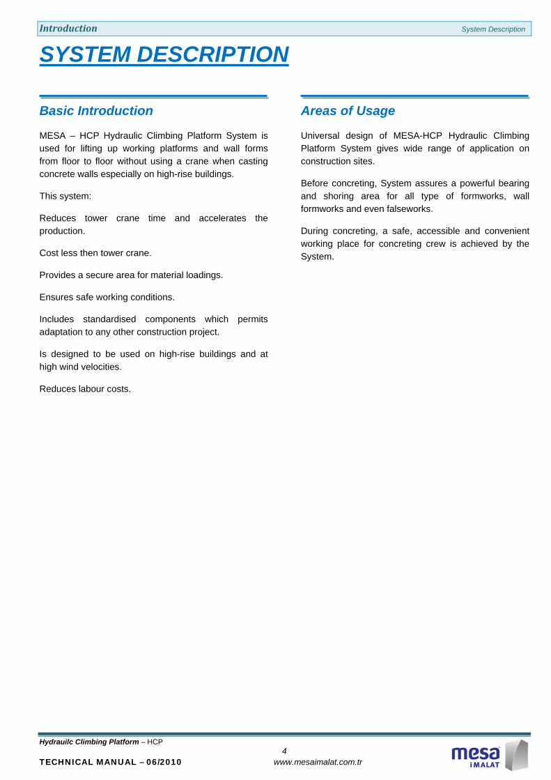
MESA – HCP Hydraulic Climbing Platform System is used for lifting up working platforms and wall forms from floor to floor without using a crane when casting concrete walls especially on high-rise buildings.
This system:
Reduces tower crane time and accelerates the production.
Cost less then tower crane.
Provides a secure area for material loadings.
Ensures safe working conditions.
Includes standardised components which permits adaptation to any other construction project.
Is designed to be used on high-rise buildings and at high wind velocities.
Reduces labour costs.
Areas of Usage
Universal design of MESA-HCP Hydraulic Climbing Platform System gives wide range of application on construction sites.
Before concreting, System assures a powerful bearing and shoring area for all type of formworks, wall formworks and even falseworks.
During concreting, a safe, accessible and convenient working place for concreting crew is achieved by the System.

Introduction Working Limits
Hydrauilc Climbing Platform – HCP 5
TECHNICAL MANUAL – 06/2010 www.mesaimalat.com.tr
WORKING LIMITS
Loading Limits
MESA – HCP System Steel Construction calculations are in accordance with DIN and FEM (Rules for the Design of Hoisting Appliances) standards.
Platform loadings are based on BSI (British Scaffolding Standards).
Materials used comply with international standards. The quality that they have is St 37.2 and St 52.2.
Unless otherwise stated, platform loading capacities are limited as described in section “Platform Levels” of this Manual.
Wind Limits
Unless any other statement is stipulated, wind limits are as follows for MESA - HCP / 100 and MESA - HCP / 200 systems:
From 0 to 72 km/h: Sheeting for protection against wind or insulation panels are kept closed. Casting is allowed Rail and platform lifting up is allowed. From 72 to 100 km/h: Sheeting for protection against wind or insulation panels are kept closed. Casting is not allowed Rail and platform lifting up is not allowed. From 100 to 165 km/h: Sheeting for protection against wind or insulation panels are kept open. Formwork operation is not allowed. Rail and platform lifting up is not allowed. Formworks are coupled face-to-face by means of tie-rods.

Introduction Scope of Applications
Hydrauilc Climbing Platform – HCP 6
TECHNICAL MANUAL – 06/2010 www.mesaimalat.com.tr
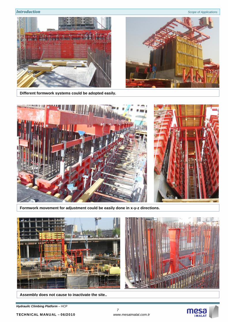
SCOPE of APPLICATIONS
Different necessities create different engineering solutions on designs and applications.
Powerful construction increases reliability of the whole system.
Pre-assembly does not need considerably wide areas.
Introduction Scope of Applications
Hydrauilc Climbing Platform – HCP 7
TECHNICAL MANUAL – 06/2010 www.mesaimalat.com.tr
Different formwork systems could be adopted easily.
Formwork movement for adjustment could be easily done in x-y-z directions.
Assembly does not cause to inactivate the site..

Introduction Scope of Applications
Hydrauilc Climbing Platform – HCP 8
TECHNICAL MANUAL – 06/2010 www.mesaimalat.com.tr
Hydraulic System succesfully operates in a long time period.
Anchoring is easy to apply.
Crane and concrete pump do not foil the application.
Other concrete working (i.e.slab or column etc.) are not affected by existing of the System.
Introduction Scope of Applications
Hydrauilc Climbing Platform – HCP 9
TECHNICAL MANUAL – 06/2010 www.mesaimalat.com.tr
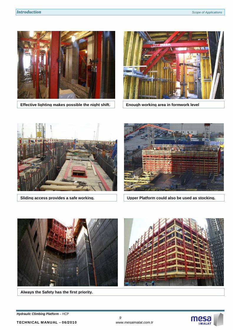
Effective lighting makes possible the night shift.
Sliding access provides a safe working.
Enough working area in formwork level
Upper Platform could also be used as stocking.
Always the Safety has the first priority.

Introduction System Overview
Hydrauilc Climbing Platform – HCP 10
TECHNICAL MANUAL – 06/2010 www.mesaimalat.com.tr
Formworks are used as being hung up on upper platform. Platform is fixed to wall from one side only.
SYSTEM OVERVIEW
HCP / 100 Type
Basic System
Anchor Set Climbing Rail Support Wheel Cylinder Set HCP/100 - Main Beam Shoe-Console Set HCP/100 - Truss Panel Hanger Set Bearing Girder
Platforms
2.Lower Platform 1.Lower Platform
Outer Platform Main Platform
Upper Platform
Introduction System Overview
Hydrauilc Climbing Platform – HCP 11
TECHNICAL MANUAL – 06/2010 www.mesaimalat.com.tr
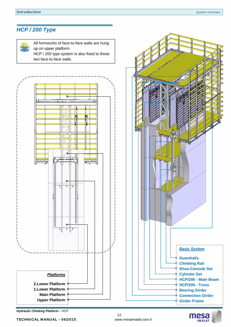
All formworks of face-to-face walls are hung up on upper platform. HCP / 200 type system is also fixed to these two face-to-face walls.
HCP / 200 Type
Platforms
2.Lower Platform 1.Lower Platform
Main Platform Upper Platform
Basic System
Guardrails Climbing Rail Shoe-Console Set Cylinder Set HCP/200 - Main Beam HCP/200 - Truss Bearing Girder Connection Girder Girder Frame
Introduction Parts
Hydrauilc Climbing Platform – HCP 12
TECHNICAL MANUAL – 06/2010 www.mesaimalat.com.tr
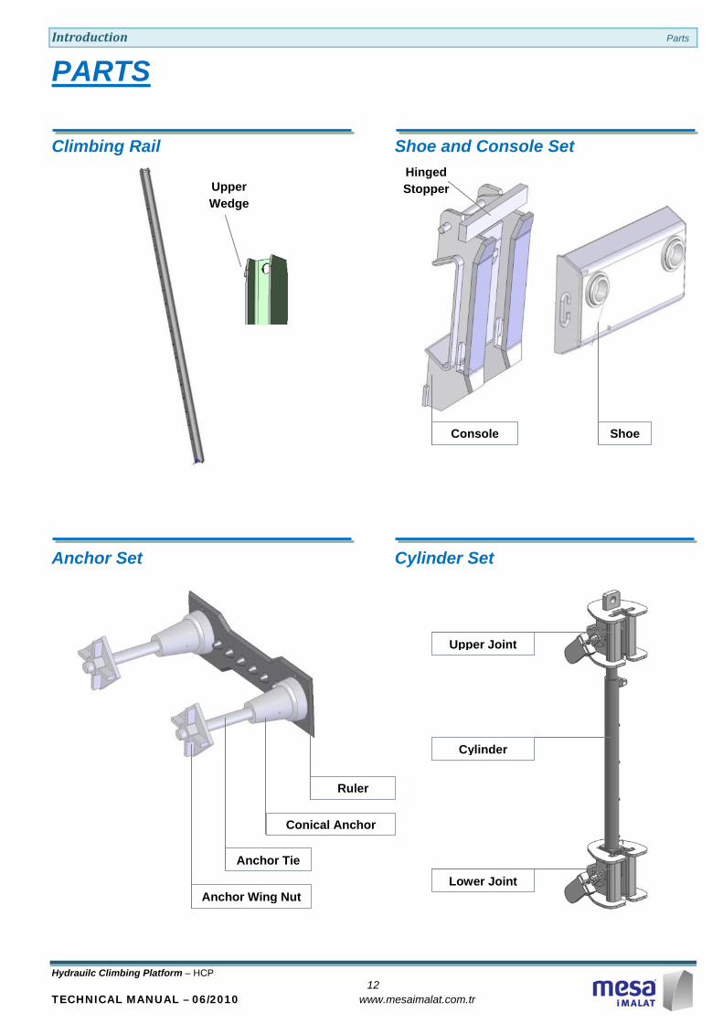
PARTS
Climbing Rail
Anchor Set
Shoe and Console Set
Cylinder Set
Shoe
Console
Ruler
Conical Anchor
Anchor Tie
Anchor Wing Nut
Hinged Stopper
Upper Wedge
Upper Joint
Cylinder
Lower Joint
Introduction Parts
Hydrauilc Climbing Platform – HCP 13
TECHNICAL MANUAL – 06/2010 www.mesaimalat.com.tr
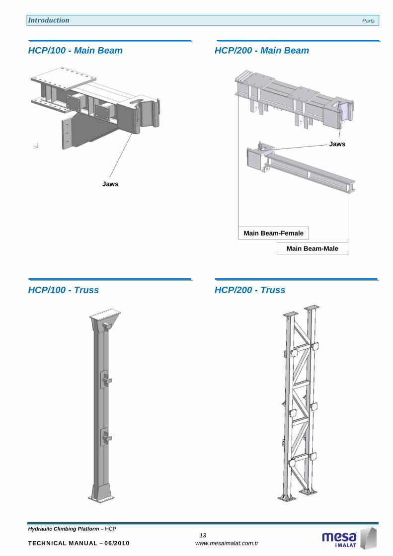
HCP/100 - Main Beam
HCP/100 - Truss
HCP/200 - Main Beam
HCP/200 - Truss
Main Beam-Male
Main Beam-Female
Jaws
Jaws

Introduction Parts
Hydrauilc Climbing Platform – HCP 14
TECHNICAL MANUAL – 06/2010 www.mesaimalat.com.tr
Panel Hanger Set
Girders
Support Wheel
Connecting Girder
Guardrail
Girder Frame
Bearing Girder
Panel Hanger
Panel Horizontal
Trolley Hanger
Trolley
Introduction Parts
Hydrauilc Climbing Platform – HCP 15
TECHNICAL MANUAL – 06/2010 www.mesaimalat.com.tr
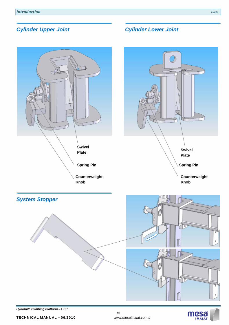
Cylinder Upper Joint
System Stopper
Cylinder Lower Joint
Swivel Plate
Counterweight Knob
Spring Pin
Swivel Plate
Spring Pin
Counterweight Knob

Basic Informations Technical Info
Hydrauilc Climbing Platform – HCP 16
TECHNICAL MANUAL – 06/2010 www.mesaimalat.com.tr
TECHNICAL INFO
Hydraulic System
Hydraulic Cylinders
MESA-HCP System uses two types of hydraulic cylinders according to the total weight of the platforms ;
Ø80 mm cylinder having 12 tons load-carrying capacity
Ø90 mm cylinder having 15 tons load-carrying capacity

Basic Informations Technical Info
Hydrauilc Climbing Platform – HCP 17
TECHNICAL MANUAL – 06/2010 www.mesaimalat.com.tr
Hydraulic Power Units
On each MESA-HCP Platform, cylinders are syncronised and controlled by MESA-Hydraulic Power Units.
HU-201006 : For HCP System having max. 4-Cylinders
HU-201006-08 : For HCP System having max. 8-Cylinders
4 Cylinders Control Unit
Working Pressure: 250 bar Maximum Pressure : 260 bar Signal Voltage : 24 VDC Main Voltage: 3 x 400 VAC
Each cylinder can be controlled one by one or multiple combination.HPU is able to work all of cylinders all together. Every cylinder can be controlled separately by own direction control valve that located on hydraulic control block.Direction control valve can determine the direction of the load.
All equipments are selected according to the 250 bar working pressure.There is a pressure relief valve (10) on the each cylinder line that adjusted 250 bar. Pressure relief valve can keep the system against over pressure.
One tandem gear pump (6) is driven by electrical motor (9). Electrical motor is selected according to the pressure and flow level.
Hydraulic pump can provide the 250 bar as nominal system pressure and also 4.5 l/min flow level as maximum. Flow level can be adjusted by flow control valve (13).
Actual pressure can be read on pressure gauge screen (12) that mounted on each line. Return line filter (5) has enough capacity to excellent filtration and protection of system. It is selected as filtration media 20 micron. Easy change of filter element and magnetic pre-filtration is possible.
Oil level and temperature can be followed by flow/temperature gauge (3).
Quick couplings provide easy connection and keeping line pressure (14).

Basic Information Platform Levels
Hydrauilc Climbing Platform – HCP 18
TECHNICAL MANUAL – 06/2010 www.mesaimalat.com.tr
Unless otherwise stated by MESA ;
Max.Loading Capacity=250 kg/m2
Unless otherwise stated by MESA ;
Max.Loading Capacity=150 kg/m2
Unless otherwise stated by MESA ;
Max.Loading Capacity=150 kg/m2
Unless otherwise stated by MESA ;
Max.Loading Capacity=75 kg/m2
PLATFORM LEVELS
Upper Platform
Positioned above the level of the wall to be cast.
It is used for concrete pouring and restricted material stock.
MainPlatform
It is the intervention level for wall forms hung on upper platform.
Formwork adjustment and rebar working are done at this level.
anchorage elements as well as bracket-shoe elements to be used for climbing up to next floor are fixed to the wall at this level.
1st.Lower Platform
Hydraulic Cylinders, hydraulic fittings and hydraulic power unit are placed at this level and are commanded from this level.
Cylinder upper and lower joints used for guiding the climbing of the system and rails are controlled from this level.
2nd.Lower Platform
Console -Shoe and Anchor elements released after climbing operation are dismounted at this level
Assembly Preperation of Concrete
Hydrauilc Climbing Platform – HCP 19
TECHNICAL MANUAL – 06/2010 www.mesaimalat.com.tr
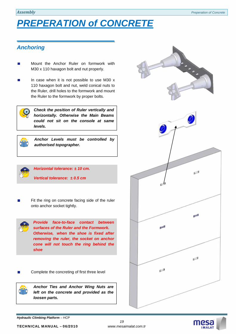
Check the position of Ruler vertically and horizontally. Otherwise the Main Beams could not sit on the console at same levels.
Anchor Levels must be controlled by authorised topographer.
Horizontal tolerance: ± 10 cm.
Vertical tolerance: ± 0.5 cm
Provide face-to-face contact between surfaces of the Ruler and the Formwork. Otherwise, when the shoe is fixed after removing the ruler, the socket on anchor cone will not touch the ring behind the shoe
Anchor Ties and Anchor Wing Nuts are left on the concrete and provided as the loosen parts.
PREPERATION of CONCRETE
Anchoring
Mount the Anchor Ruler on formwork with M30 x 110 haxagon bolt and nut properly.
In case when it is not possible to use M30 x 110 haxagon bolt and nut, weld conical nuts to the Ruler, drill holes to the formwork and mount the Ruler to the formwork by proper bolts.
Fit the ring on concrete facing side of the ruler onto anchor socket tightly.
Complete the concreting of first three level
Assembly Preperation of Concrete
Hydrauilc Climbing Platform – HCP 20
TECHNICAL MANUAL – 06/2010 www.mesaimalat.com.tr
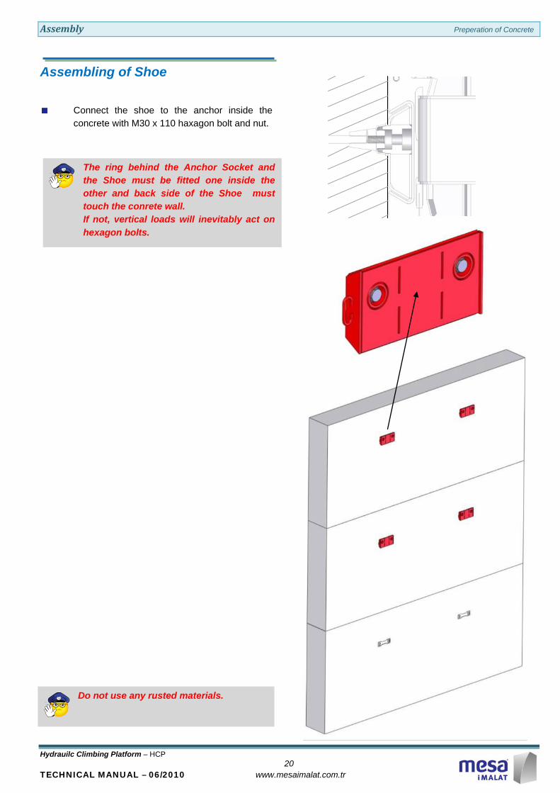
The ring behind the Anchor Socket and the Shoe must be fitted one inside the other and back side of the Shoe must touch the conrete wall. If not, vertical loads will inevitably act on hexagon bolts.
Do not use any rusted materials.
Assembling of Shoe
Connect the shoe to the anchor inside the concrete with M30 x 110 haxagon bolt and nut.
Assembly Preperation of Concrete
Hydrauilc Climbing Platform – HCP 21
TECHNICAL MANUAL – 06/2010 www.mesaimalat.com.tr
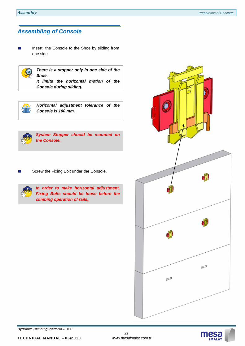
There is a stopper only in one side of the Shoe. It limits the horizontal motion of the Console during sliding.
Horizontal adjustment tolerance of the Console is 100 mm.
System Stopper should be mounted on the Console.
In order to make horizontal adjustment, Fixing Bolts should be loose before the climbing operation of rails,,
Assembling of Console
Insert the Console to the Shoe by sliding from one side.
Screw the Fixing Bolt under the Console.

Assembly Assembly of the Main&Lower Platforms
Hydraulic Climbing Platform – HCP 22
TECHNICAL MANUAL – 06/2010 www.mesaimalat.com.tr
Pre-assembly should be realised by the componenets (bolts, nuts, pins etc.) described in “Assembly Booklet” provided by MESA “Assembly Booklet” is prepared according to the Construction project of the Customer.
Ensure the horizontality of the System.
Conform all safety regulations during crane operation.
Check all type of components and their quantities according to the tables in section “Assembly Booklet” provided by MESA .
ASSEMBLY of the MAIN&LOWER PLT.s
Assembly of 1st.Lower and Main Platform
Mount the Pre-assembled Set (1st.Lower Platform Beams and Trusses, and Main Platform Beams and Platform Bearing Profiles) onto the Consoles.
Adjust the horizontality of the System by Supporting Wheels.

Assembly Assembly of the Main&Lower Platforms
Hydraulic Climbing Platform – HCP 23
TECHNICAL MANUAL – 06/2010 www.mesaimalat.com.tr
Observe that the cylinder of Cylinder is on top and rod of the Cylinder is at the bottom.
Assembly of Hydrauilc Cylinders
Mount the Upper Joint to cage under the Main Beam with the Bearing Pin supplied.
Mount the Cylinder to the Upper Joint.
Mount the Lower Joint to the Cylinder.

Assembly Assembly of the Main&Lower Platforms
Hydraulic Climbing Platform – HCP 24
TECHNICAL MANUAL – 06/2010 www.mesaimalat.com.tr
Hinged Stopper should be turned down.
Assembly of Climbing Rail
Pass the Climbing Rail through the gaps on the Console and the Jaws of Main Beam.
Pass the Climbing Rail through the gap on the Supporting Wheel.
Fit the Upper Wedges on the Rail to the Hinged Stopper.
Assembly Assembly of the Main&Lower Platforms
Hydraulic Climbing Platform – HCP 25
TECHNICAL MANUAL – 06/2010 www.mesaimalat.com.tr
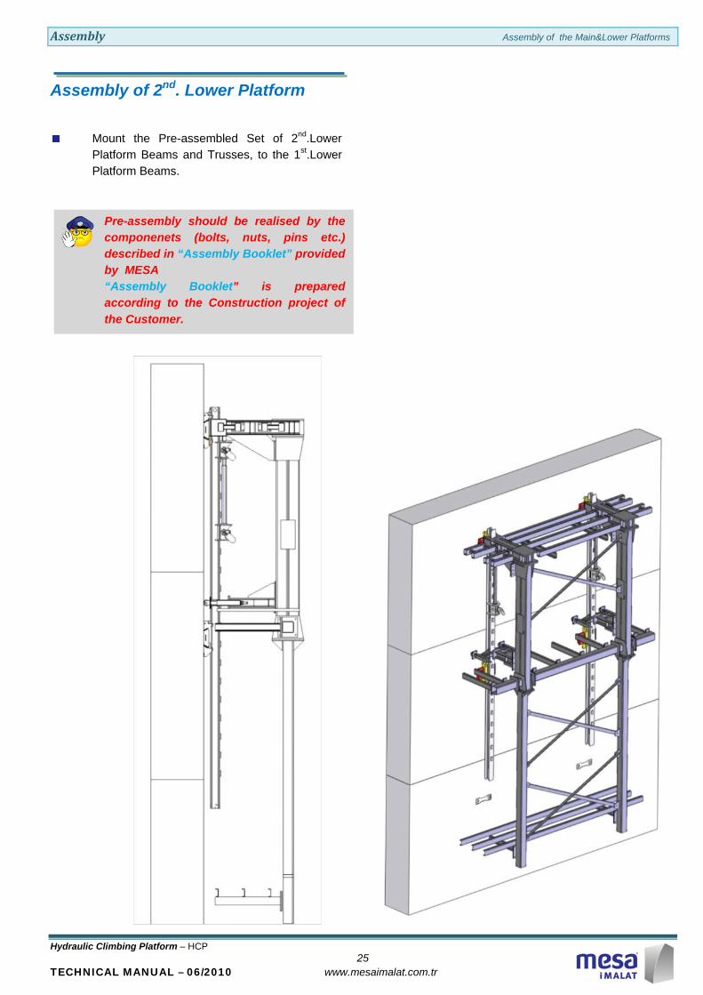
Pre-assembly should be realised by the componenets (bolts, nuts, pins etc.) described in “Assembly Booklet” provided by MESA “Assembly Booklet” is prepared according to the Construction project of the Customer.
Assembly of 2nd. Lower Platform
Mount the Pre-assembled Set of 2nd.Lower Platform Beams and Trusses, to the 1st.Lower Platform Beams.

Assembly Assembly of the Main&Lower Platforms
Hydraulic Climbing Platform – HCP 26
TECHNICAL MANUAL – 06/2010 www.mesaimalat.com.tr
Do not use damaged or knotty woods.
Check fructure existance on all wooden materials.
Lengths and sections of Timbers to be used are tabulated on “Assembly Booklet” provided by MESA.
If H20 Timber Beam is selected as Timber Girder, use H20 Clips provided by MESA for connection of steel brackets and H20 Beams.
Timber Covering of Main and Lower Platforms
Start with assemblying of Timber Girders and Timber Covers on 2nd.Lower Platform.
Assemble Timber Girders and Timber Covers on 1st.Lower Platform.
Insert Sliding Gate on 1st.Lower Platform for access.
Assemble Timber Girders and Timber Covers on Main Platform.
Insert Sliding Gate on Main Platform for access.
Mount the Ladders
Assembly Assembly of the Upper Platform
Hydrauilc Climbing Platform – HCP 27
TECHNICAL MANUAL – 06/2010 www.mesaimalat.com.tr
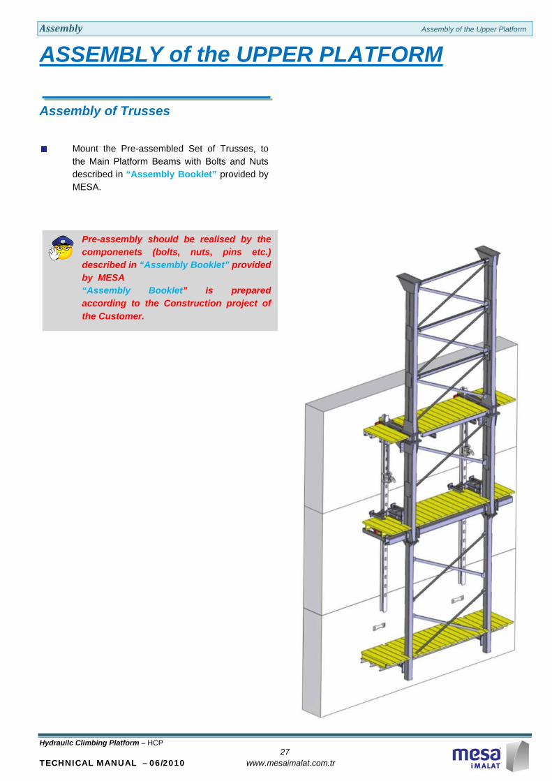
Pre-assembly should be realised by the componenets (bolts, nuts, pins etc.) described in “Assembly Booklet” provided by MESA “Assembly Booklet” is prepared according to the Construction project of the Customer.
ASSEMBLY of the UPPER PLATFORM
Assembly of Trusses
Mount the Pre-assembled Set of Trusses, to the Main Platform Beams with Bolts and Nuts described in “Assembly Booklet” provided by MESA.
Assembly Assembly of the Upper Platform
Hydrauilc Climbing Platform – HCP 28
TECHNICAL MANUAL – 06/2010 www.mesaimalat.com.tr
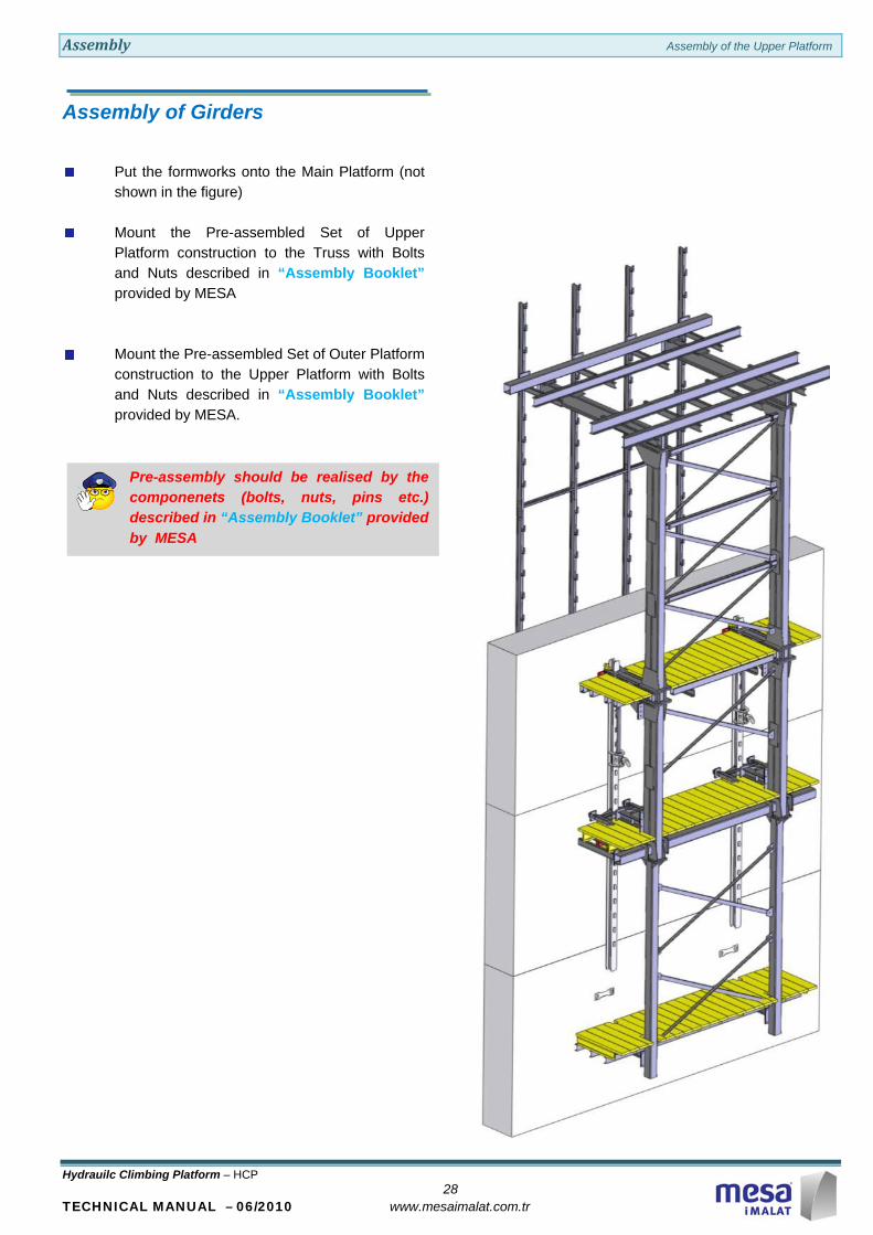
Pre-assembly should be realised by the componenets (bolts, nuts, pins etc.) described in “Assembly Booklet” provided by MESA
Assembly of Girders
Put the formworks onto the Main Platform (not shown in the figure)
Mount the Pre-assembled Set of Upper Platform construction to the Truss with Bolts and Nuts described in “Assembly Booklet” provided by MESA
Mount the Pre-assembled Set of Outer Platform construction to the Upper Platform with Bolts and Nuts described in “Assembly Booklet” provided by MESA.
Assembly Assembly of Formworks
Hydrauilc Climbing Platform – HCP 29
TECHNICAL MANUAL – 06/2010 www.mesaimalat.com.tr
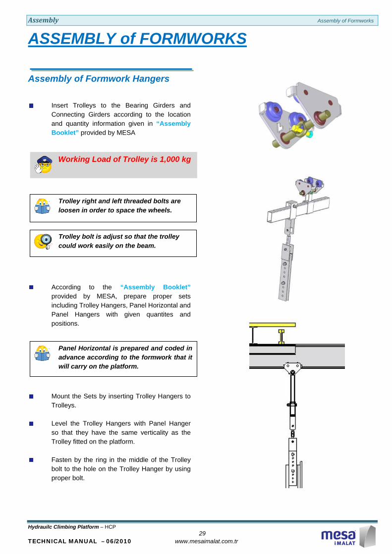
Working Load of Trolley is 1,000 kg
Trolley right and left threaded bolts are loosen in order to space the wheels.
Trolley bolt is adjust so that the trolley could work easily on the beam.
Panel Horizontal is prepared and coded in advance according to the formwork that it will carry on the platform.
ASSEMBLY of FORMWORKS
Assembly of Formwork Hangers
Insert Trolleys to the Bearing Girders and Connecting Girders according to the location and quantity information given in “Assembly Booklet” provided by MESA
According to the “Assembly Booklet” provided by MESA, prepare proper sets including Trolley Hangers, Panel Horizontal and Panel Hangers with given quantites and positions.
Mount the Sets by inserting Trolley Hangers to Trolleys.
Level the Trolley Hangers with Panel Hanger so that they have the same verticality as the Trolley fitted on the platform.
Fasten by the ring in the middle of the Trolley bolt to the hole on the Trolley Hanger by using proper bolt.
Assembly Assembly of Formworks
Hydrauilc Climbing Platform – HCP 30
TECHNICAL MANUAL – 06/2010 www.mesaimalat.com.tr
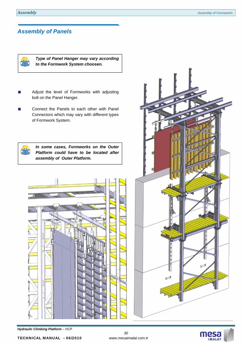
Type of Panel Hanger may vary according to the Formwork System choosen.
In some cases, Formworks on the Outer Platform could have to be located after assembly of Outer Platform.
Assembly of Panels
Adjust the level of Formworks with adjusting bolt on the Panel Hanger.
Connect the Panels to each other with Panel Connectors which may vary with different types of Formwork System.

Assembly Finishing the Assembly
Hydrauilc Climbing Platform – HCP 31
TECHNICAL MANUAL – 06/2010 www.mesaimalat.com.tr
Do not use damaged or knotty woods.
Check fructure existance on all wooden materials.
Lengths and sections of Timbers to be used are tabulated on “Assembly Booklet” provided by MESA.
If H20 Timber Beam is selected as Timber Girder, use H20 Clips provided by MESA for connection of steel brackets and H20 Beams.
The gap between Upper and Outer Platforms could be closed by a hinged or portable platforms.
FINISHING the ASSEMBLY
Timber Covering of Upper Platform
Start with assemblying of Timber Girders and Timber Covers on Upper Platform.
Insert Sliding Gate on Upper Platform for access.
Mount the Ladders.

Assembly Finishing the Assembly
Hydrauilc Climbing Platform – HCP 32
TECHNICAL MANUAL – 06/2010 www.mesaimalat.com.tr
Check fructure existance on all wooden materials.
Lengths and sections of Guardrail and Bearing Timbers to be used are tabulated on “Assembly Booklet” provided by MESA.
Do not use damaged or knotty woods.
All Guardrail Timbers should be mounted on Outer Platforms.
Make sure the required safety conditions are provided.
Observe the Plinth Timber is properly installed.
Assembly of Guardrails and Outer Platform
Start with assemblying of Timber Girders and Timber Covers on Outer Platform.
Insert Sliding Gate on Outer Platform for access.
Mount the Ladders
Assembly Finishing the Assembly
Hydrauilc Climbing Platform – HCP 33
TECHNICAL MANUAL – 06/2010 www.mesaimalat.com.tr
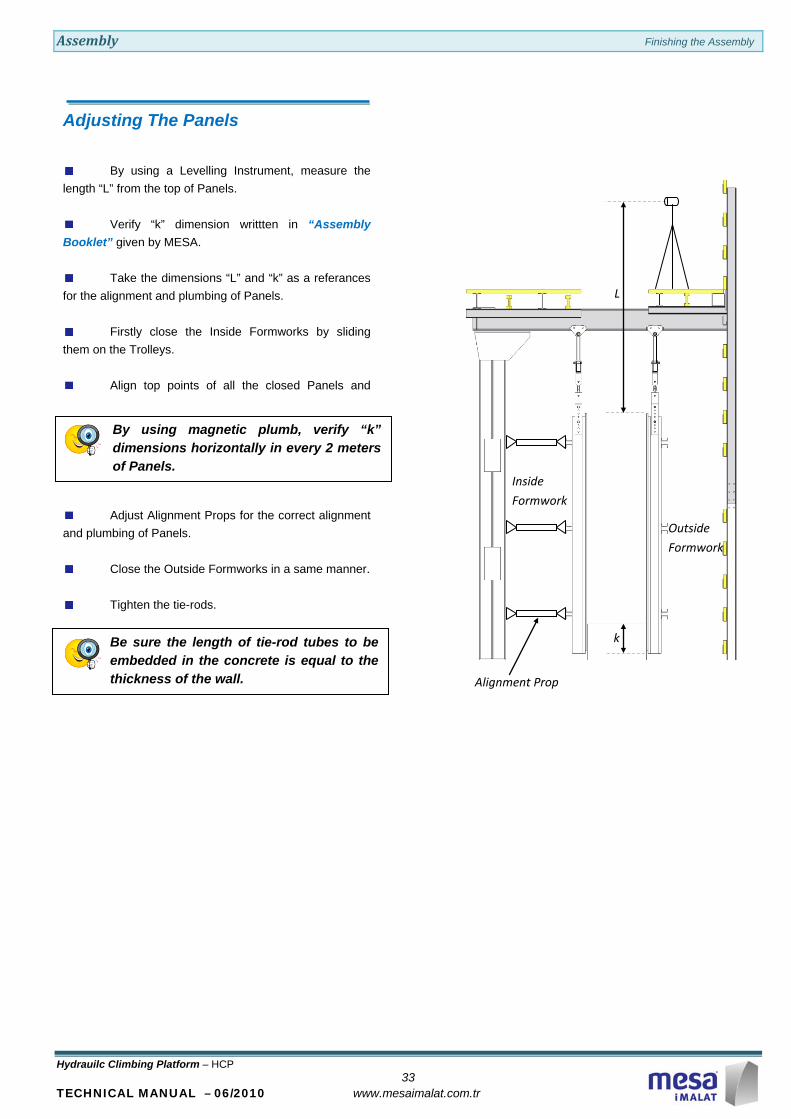
By using magnetic plumb, verify “k” dimensions horizontally in every 2 meters of Panels.
Be sure the length of tie-rod tubes to be embedded in the concrete is equal to the thickness of the wall.
Adjusting The Panels
By using a Levelling Instrument, measure the length “L” from the top of Panels.
Verify “k” dimension writtten in “Assembly Booklet” given by MESA.
Take the dimensions “L” and “k” as a referances for the alignment and plumbing of Panels.
Firstly close the Inside Formworks by sliding them on the Trolleys.
Align top points of all the closed Panels and
L
k
Inside Formwork
Outside Formwork
Alignment Prop
Adjust Alignment Props for the correct alignment and plumbing of Panels.
Close the Outside Formworks in a same manner.
Tighten the tie-rods.
Maintenance Maintenance
Hydrauilc Climbing Platform – HCP 34
TECHNICAL MANUAL – 06/2010 www.mesaimalat.com.tr
MAINTENANCE
• Authorised person responsible from HCP System must know and carry out all the points explained in this manual and make them applied by concerned persons.
• The temperature and wind velocities must be observed permanently and working operation must be arranged according to the limits indicated in this msnual.
• Interval of Periodical Checks must not exceed one month. User could shorten this period.
• Rails must be lubricated all times. Check grease levels.
• Weldings must be observed periodically.
• Working operation must be stopped immediately if any welding show cracking and manufacturer must be informed without delay.
• All bolts of the construction must be checked, fastened or replaced if needed.
• All platform and guardrail timber beams must be checked periodically.
• Formwork hanging devices must be checked periodically.
Hydraulic System
HCP Platforms
• At least, one person (HCP Chief) must be entrusted with the checking of the Hydraulic Power Unit.
Daily Maintenance;
• Hydraulic oil level should be checked.
• If oil level below the indicator line, add enough oil (type of oil must be checked).
• All of the indicator line should be checked against oil leakage and unwanted outflow.
Weekly Maintenance;
• Motor current should be controlled.
• Pump’s noise level and vibration level should be checked.
Monthly Maintenance;
• Pressure gauge calibrations should be checked.
• Oil viscosity and color should be checked.
Half Yearly Maintenance;
• Return line filter element should be changed.
• On each platform level, have at your disposal
an extinguisher against danger of fire!

Notes
Hydraulic Climbing Platform – HCP
TECHNICAL MANUAL – 06/2010 www.mesaimalat.com.tr