hydraulic cylinders - abitibi-té · pdf filehydraulic cylinders hydraulic valves mobile...
TRANSCRIPT
Catalogue
Visit our w
ebsite
www.Hy-s
pec.com
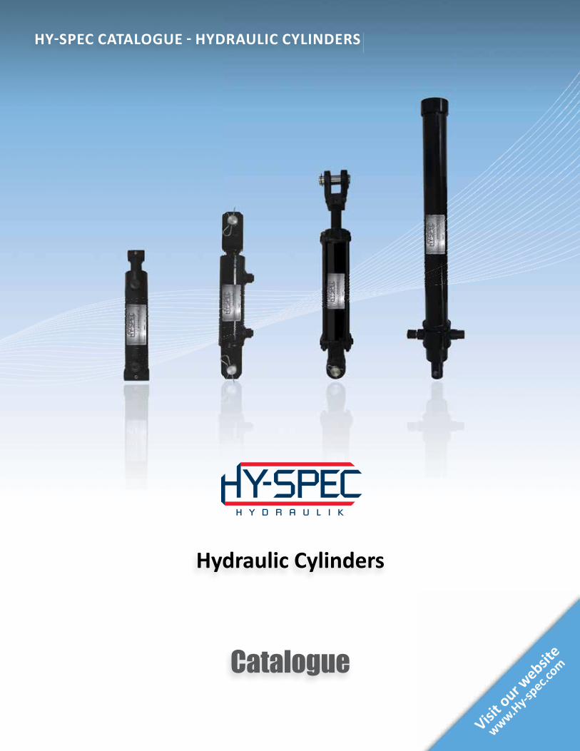
Hydraulic Cylinders
HY-SPEC CATALOGUE - HYDRAULIC CYLINDERS
WIC-EN-CATALOGUES-COVERS-2012-DYNAMIC-16.indd 13 2014-05-02 16:26:35

1 . 8 6 6 . 5 4 6 . 3 2 6 7 www.Hy-spec.com
ASK FOR HY-SPEC QUALITYNote: Actual products may differ from photos shown in this brochure.
Product availability and specifications are subject to change without notice.2
For more information or for OEM requests
1.866.546.3267To fi nd a Hy-Spec retailer near you
Hy-spec.com
Catalogue
Visit our w
ebsite
www.Hy-s
pec.com
Accessories
HY-SPEC CATALOGUE - ACCESSORIES
WIC-EN-CATALOGUES-COVERS-2012-DYNAMIC-16.indd 17 2014-05-02 16:27:19
Catalogue
Visit our w
ebsite
www.Hy-s
pec.com
AC/DC Power Packs
HY-SPEC CATALOGUE - AC/DC POWER PACKS
WIC-EN-CATALOGUES-COVERS-2012-DYNAMIC-16.indd 5 2014-05-02 16:25:52
Catalogue
Visit our w
ebsite
www.Hy-s
pec.com
Gas Engine Products
HY-SPEC CATALOGUE - GAS ENGINE PRODUCTS
WIC-EN-CATALOGUES-COVERS-2012-DYNAMIC-16.indd 9 2014-05-02 16:26:15
Catalogue
Visit our w
ebsite
www.Hy-s
pec.com
Hydraulic Cylinders
HY-SPEC CATALOGUE - HYDRAULIC CYLINDERS
WIC-EN-CATALOGUES-COVERS-2012-DYNAMIC-16.indd 13 2014-05-02 16:26:35
Catalogue
Visit our w
ebsite
www.Hy-s
pec.com
Hydraulic Valves
HY-SPEC CATALOGUE - HYDRAULIC VALVES
WIC-EN-CATALOGUES-COVERS-2012-DYNAMIC-16.indd 1 2014-05-02 16:25:26
Catalogue
Visit our w
ebsite
www.Hy-s
pec.com
Mobile Directi onal Control Valves
HY-SPEC CATALOGUE - MOBILE DIRECTIONAL CONTROL VALVES
WIC-EN-CATALOGUES-COVERS-2012-DYNAMIC-16.indd 21 2014-05-02 16:27:41
Accessories AC/DC Power Packs Gas Engine Products Hydraulic Cylinders Hydraulic Valves Mobile Directional Control Valves
HY-SPEC CARRIES A COMPREHENSIVE SELECTION OF HIGH QUALITY HYDRAULIC PRODUCTS
HY-SPEC PRODUCT FAMILY
WIC-EN-CATALOGUES-COVERS-2012-DYNAMIC-16.indd 2 2014-05-02 16:40:08
ASK FOR HY-SPEC QUALITYNote: Actual products may differ from photos shown in this brochure.Product availability and specifications are subject to change without notice.
1 . 8 6 6 . 5 4 6 . 3 2 6 7 www.Hy-spec.com 3
Ta
ble
of C
on
ten
ts
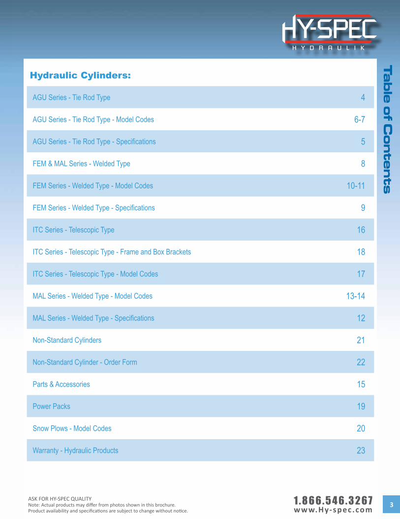
Hydraulic Cylinders:
AGU Series - Tie Rod Type 4
AGU Series - Tie Rod Type - Model Codes 6-7
AGU Series - Tie Rod Type - Specifications 5
FEM & MAL Series - Welded Type 8
FEM Series - Welded Type - Model Codes 10-11
FEM Series - Welded Type - Specifications 9
ITC Series - Telescopic Type 16
ITC Series - Telescopic Type - Frame and Box Brackets 18
ITC Series - Telescopic Type - Model Codes 17
MAL Series - Welded Type - Model Codes 13-14
MAL Series - Welded Type - Specifications 12
Non-Standard Cylinders 21
Non-Standard Cylinder - Order Form 22
Parts & Accessories 15
Power Packs 19
Snow Plows - Model Codes 20
Warranty - Hydraulic Products 23
1 . 8 6 6 . 5 4 6 . 3 2 6 7 www.Hy-spec.com
ASK FOR HY-SPEC QUALITYNote: Actual products may differ from photos shown in this brochure.
Product availability and specifications are subject to change without notice.4
AG
U S
eri
es
- T
ie R
od
Ty
pe
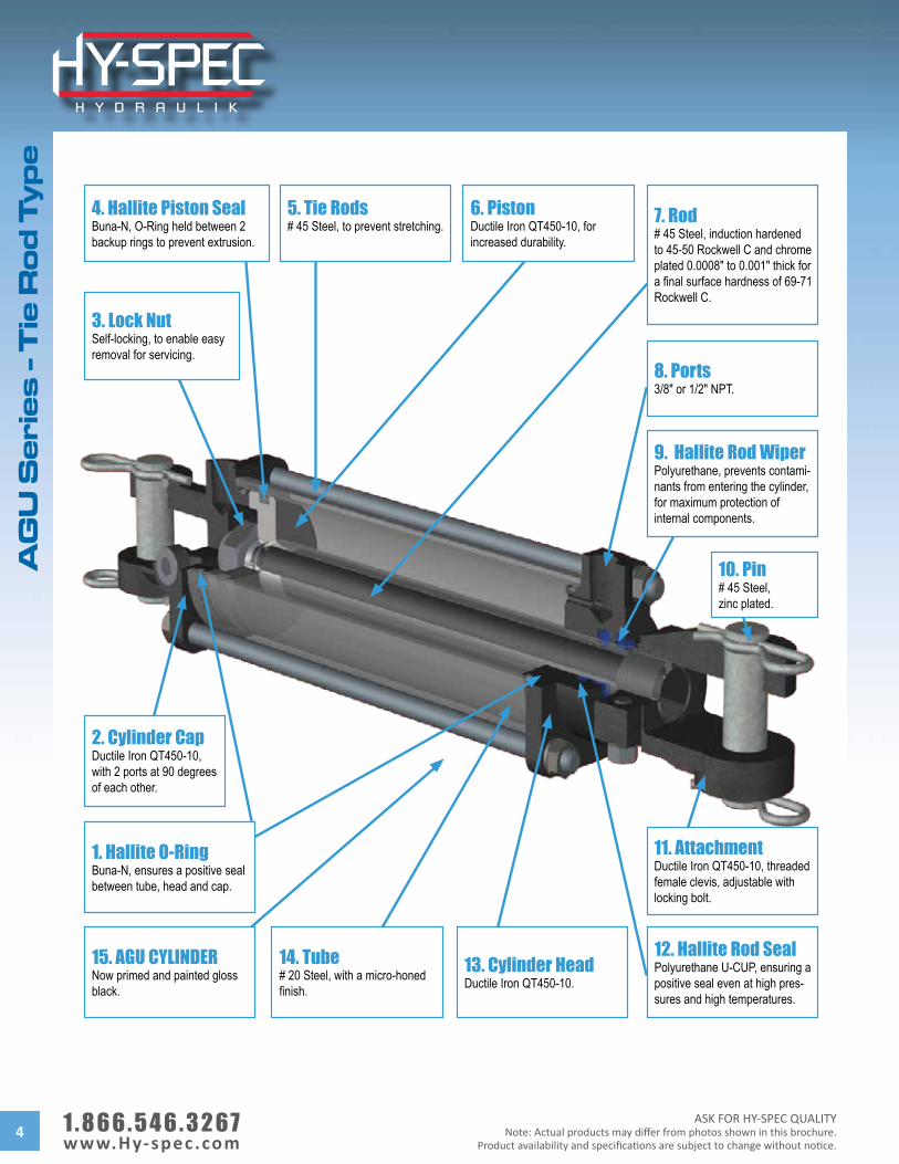
5. Tie Rods# 45 Steel, to prevent stretching. 7. Rod
# 45 Steel, induction hardened to 45-50 Rockwell C and chrome plated 0.0008" to 0.001" thick for a final surface hardness of 69-71 Rockwell C.
8. Ports3/8" or 1/2" NPT.
9. Hallite Rod WiperPolyurethane, prevents contami-nants from entering the cylinder, for maximum protection ofinternal components.
11. AttachmentDuctile Iron QT450-10, threaded female clevis, adjustable with locking bolt.
4. Hallite Piston SealBuna-N, O-Ring held between 2 backup rings to prevent extrusion.
12. Hallite Rod SealPolyurethane U-CUP, ensuring a positive seal even at high pres-sures and high temperatures.
13. Cylinder HeadDuctile Iron QT450-10.
14. Tube# 20 Steel, with a micro-honed finish.
1. Hallite O-RingBuna-N, ensures a positive seal between tube, head and cap.
3. Lock NutSelf-locking, to enable easy removal for servicing.
2. Cylinder CapDuctile Iron QT450-10, with 2 ports at 90 degrees of each other.
10. Pin# 45 Steel, zinc plated.
15. AGU CYLINDERNow primed and painted gloss black.
6. PistonDuctile Iron QT450-10, for increased durability.
ASK FOR HY-SPEC QUALITYNote: Actual products may differ from photos shown in this brochure.Product availability and specifications are subject to change without notice.
1 . 8 6 6 . 5 4 6 . 3 2 6 7 www.Hy-spec.com 5
AG
U S
erie
s - T
ie R
od
Ty
pe
- Sp
ec
ifica
tion
s
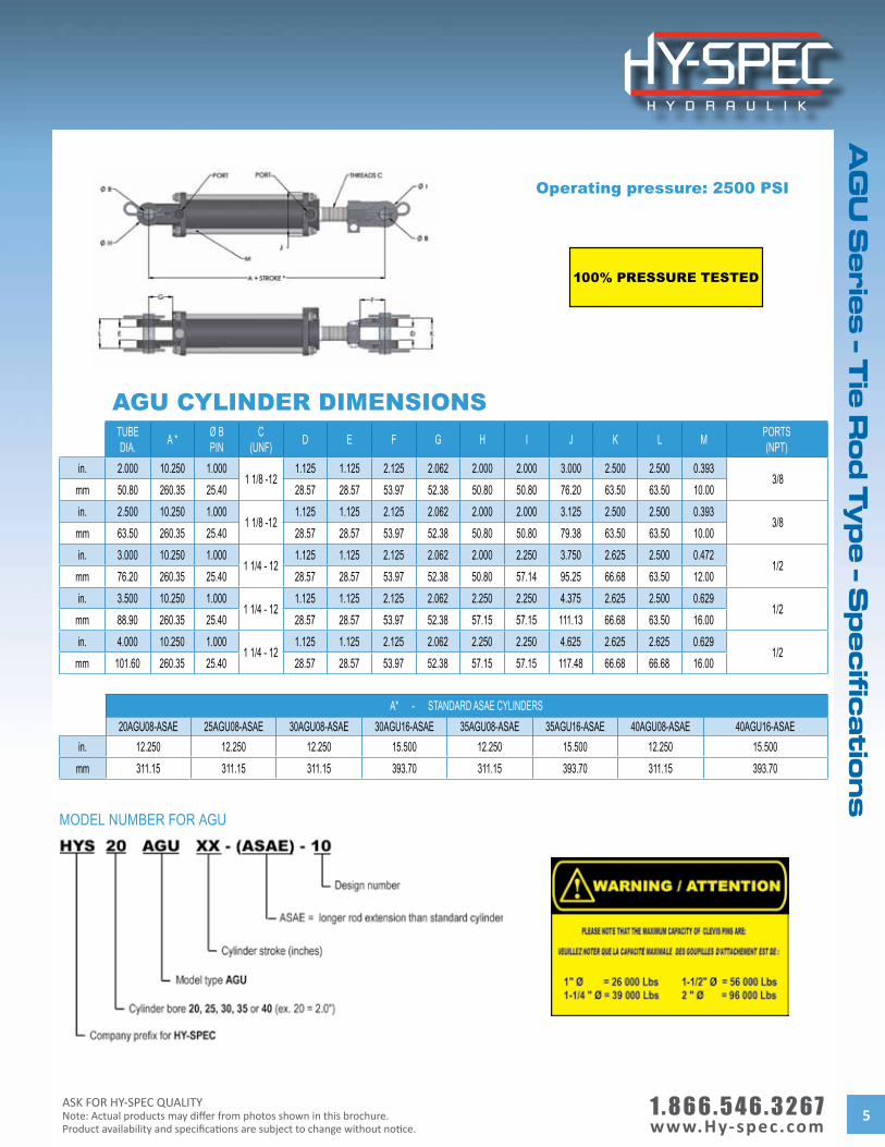
TUBEDIA. A * Ø B
PINC
(UNF) D E F G H I J K L M PORTS(NPT)
in. 2.000 10.250 1.0001 1/8 -12
1.125 1.125 2.125 2.062 2.000 2.000 3.000 2.500 2.500 0.393 3/8
mm 50.80 260.35 25.40 28.57 28.57 53.97 52.38 50.80 50.80 76.20 63.50 63.50 10.00in. 2.500 10.250 1.000
1 1/8 -121.125 1.125 2.125 2.062 2.000 2.000 3.125 2.500 2.500 0.393
3/8mm 63.50 260.35 25.40 28.57 28.57 53.97 52.38 50.80 50.80 79.38 63.50 63.50 10.00in. 3.000 10.250 1.000
1 1/4 - 121.125 1.125 2.125 2.062 2.000 2.250 3.750 2.625 2.500 0.472
1/2mm 76.20 260.35 25.40 28.57 28.57 53.97 52.38 50.80 57.14 95.25 66.68 63.50 12.00in. 3.500 10.250 1.000
1 1/4 - 121.125 1.125 2.125 2.062 2.250 2.250 4.375 2.625 2.500 0.629
1/2mm 88.90 260.35 25.40 28.57 28.57 53.97 52.38 57.15 57.15 111.13 66.68 63.50 16.00in. 4.000 10.250 1.000
1 1/4 - 121.125 1.125 2.125 2.062 2.250 2.250 4.625 2.625 2.625 0.629
1/2mm 101.60 260.35 25.40 28.57 28.57 53.97 52.38 57.15 57.15 117.48 66.68 66.68 16.00
A* - STANDARD ASAE CYLINDERS20AGU08-ASAE 25AGU08-ASAE 30AGU08-ASAE 30AGU16-ASAE 35AGU08-ASAE 35AGU16-ASAE 40AGU08-ASAE 40AGU16-ASAE
in. 12.250 12.250 12.250 15.500 12.250 15.500 12.250 15.500mm 311.15 311.15 311.15 393.70 311.15 393.70 311.15 393.70
MODEL NUMBER FOR AGU
AGU CYLINDER DIMENSIONS
Operating pressure: 2500 PSI
100% PRESSURE TESTED
1 . 8 6 6 . 5 4 6 . 3 2 6 7 www.Hy-spec.com
ASK FOR HY-SPEC QUALITYNote: Actual products may differ from photos shown in this brochure.
Product availability and specifications are subject to change without notice.6
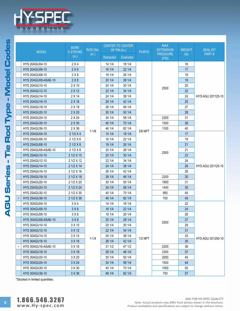
AG
U S
eri
es
- T
ie R
od
Ty
pe
- M
od
el C
od
es
MODELBORE
X STROKE(in.)
ROD DIA.(in.)
CENTER TO CENTEROF PIN (in.) PORTS
MAXEXTENSION PRESSURE
(PSI)
WEIGHT(lb)
SEAL KITPART #
Retracted Extended
HYS 20AGU04-10 2 X 4
1-1/8
14 1/4 18 1/4
3/8 NPT
2500
16
HYS AGU 201125-10
HYS 20AGU06-10 2 X 6 16 1/4 22 1/4 17HYS 20AGU08-10 2 X 8 18 1/4 26 1/4 19HYS 20AGU08-ASAE-10 2 X 8 20 1/4 28 1/4 19HYS 20AGU10-10 2 X 10 20 1/4 30 1/4 20HYS 20AGU12-10 2 X 12 22 1/4 34 1/4 22HYS 20AGU14-10 2 X 14 24 1/4 38 1/4 24HYS 20AGU16-10 2 X 16 26 1/4 42 1/4 25HYS 20AGU18-10 2 X 18 28 1/4 46 1/4 27HYS 20AGU20-10 2 X 20 30 1/4 50 1/4 28HYS 20AGU24-10 2 X 24 34 1/4 58 1/4 2200 31HYS 20AGU30-10 2 X 30 40 1/4 70 1/4 1500 36HYS 20AGU36-10 2 X 36 46 1/4 82 1/4 1100 40HYS 25AGU04-10 2 1/2 X 4 14 1/4 18 1/4
2500
17
HYS AGU 251125-10
HYS 25AGU06-10 2 1/2 X 6 16 1/4 22 1/4 19HYS 25AGU08-10 2 1/2 X 8 18 1/4 26 1/4 21HYS 25AGU08-ASAE-10 2 1/2 X 8 20 1/4 28 1/4 21HYS 25AGU10-10 2 1/2 X 10 20 1/4 30 1/4 23HYS 25AGU12-10 2 1/2 X 12 22 1/4 34 1/4 24HYS 25AGU14-10 2 1/2 X 14 24 1/4 38 1/4 26HYS 25AGU16-10 2 1/2 X 16 26 1/4 42 1/4 28HYS 25AGU18-10 2 1/2 X 18 28 1/4 46 1/4 2200 30HYS 25AGU20-10 2 1/2 X 20 30 1/4 50 1/4 1900 31HYS 25AGU24-10 2 1/2 X 24 34 1/4 58 1/4 1400 35HYS 25AGU30-10 2 1/2 X 30 40 1/4 70 1/4 950 40
* HYS 25AGU36-10 2 1/2 X 36 46 1/4 82 1/4 700 45HYS 30AGU04-10 3 X 4
1-1/4
14 1/4 18 1/4
1/2 NPT
2500
22
HYS AGU 301250-10
HYS 30AGU06-10 3 X 6 16 1/4 22 1/4 24HYS 30AGU08-10 3 X 8 18 1/4 26 1/4 26HYS 30AGU08-ASAE-10 3 X 8 20 1/4 28 1/4 27HYS 30AGU10-10 3 X 10 20 1/4 30 1/4 29HYS 30AGU12-10 3 X 12 22 1/4 34 1/4 31HYS 30AGU14-10 3 X 14 24 1/4 38 1/4 33HYS 30AGU16-10 3 X 16 26 1/4 42 1/4 35
* HYS 30AGU16-ASAE-10 3 X 16 31 1/2 47 1/2 2200 36HYS 30AGU18-10 3 X 18 28 1/4 46 1/4 2300 37HYS 30AGU20-10 3 X 20 30 1/4 50 1/4 2000 40HYS 30AGU24-10 3 X 24 34 1/4 58 1/4 1500 44HYS 30AGU30-10 3 X 30 40 1/4 70 1/4 1000 50HYS 30AGU36-10 3 X 36 46 1/4 82 1/4 750 57
*Stocked in limited quantities.
ASK FOR HY-SPEC QUALITYNote: Actual products may differ from photos shown in this brochure.Product availability and specifications are subject to change without notice.
1 . 8 6 6 . 5 4 6 . 3 2 6 7 www.Hy-spec.com 7
AG
U S
erie
s - T
ie R
od
Ty
pe
- Mo
de
l Co
de
s
MODELBORE
X STROKE(in.)
ROD DIA.(in.)
CENTER TO CENTEROF PIN (in.) PORTS
MAXEXTENSION PRESSURE
(PSI)
WEIGHT(lb)
SEAL KITPART #
Retracted Extended
* HYS 35AGU04-10 3 1/2 X 4
1-1/4
14 1/4 18 1/4
1/2 NPT
2500
29
HYS AGU 351250-10
* HYS 35AGU06-10 3 1/2 X 6 16 1/4 22 1/4 31HYS 35AGU08-10 3 1/2 X 8 18 1/4 26 1/4 34HYS 35AGU08-ASAE-10 3 1/2 X 8 20 1/4 28 1/4 35HYS 35AGU10-10 3 1/2 X 10 20 1/4 30 1/4 37HYS 35AGU12-10 3 1/2 X 12 22 1/4 34 1/4 39HYS 35AGU14-10 3 1/2 X 14 24 1/4 38 1/4 42HYS 35AGU16-10 3 1/2 X 16 26 1/4 42 1/4 2000 44
* HYS 35AGU16-ASAE-10 3 1/2 X 16 31 1/2 47 1/2 1600 45HYS 35AGU18-10 3 1/2 X 18 28 1/4 46 1/4 1700 47HYS 35AGU20-10 3 1/2 X 20 30 1/4 50 1/4 1400 50HYS 35AGU24-10 3 1/2 X 24
1-1/234 1/4 58 1/4 2200 59
HYS AGU 351500-10 HYS 35AGU30-10 3 1/2 X 30 40 1/4 70 1/4 1500 68
* HYS 35AGU36-10 3 1/2 X 36 46 1/4 82 1/4 1100 76* HYS 40AGU04-10 4 X 4
1-1/4
14 1/4 18 1/4
2500
34
HYS AGU 401250-10
* HYS 40AGU06-10 4 X 6 16 1/4 22 1/4 37HYS 40AGU08-10 4 X 8 18 1/4 26 1/4 40HYS 40AGU08-ASAE-10 4 X 8 20 1/4 28 1/4 40HYS 40AGU10-10 4 X 10 20 1/4 30 1/4 43HYS 40AGU12-10 4 X 12 22 1/4 34 1/4 2400 45HYS 40AGU14-10 4 X 14 24 1/4 38 1/4 1900 48HYS 40AGU16-10 4 X 16 26 1/4 42 1/4 1600 51
HYS 40AGU16-ASAE-10 4 X 16 2 31 1/2 47 1/22500
60 HYS AGU 402000-10
HYS 40AGU18-10 4 X 181-1/2
28 1/4 46 1/4 57 HYS AGU 401500-10 HYS 40AGU20-10 4 X 20 30 1/4 50 1/4 2300 60
HYS 40AGU24-150-10 4 X 24 34 1/4 58 1/4 1700 66
HYS 40AGU24-175-10 4 X 24 1-3/4 34 1/4 58 1/4
2500
70 HYS AGU 401750-10
HYS 40AGU24-200-10 4 X 242
34 1/4 58 1/4 75 HYS AGU 402000-10 HYS 40AGU30-10 4 X 30 40 1/4 70 1/4 87
HYS 40AGU36-10 4 X 36 46 1/4 82 1/4 98
*Stocked in limited quantities.
1 . 8 6 6 . 5 4 6 . 3 2 6 7 www.Hy-spec.com
ASK FOR HY-SPEC QUALITYNote: Actual products may differ from photos shown in this brochure.
Product availability and specifications are subject to change without notice.8
FE
M &
MA
L S
eri
es
- W
eld
ed
Ty
pe
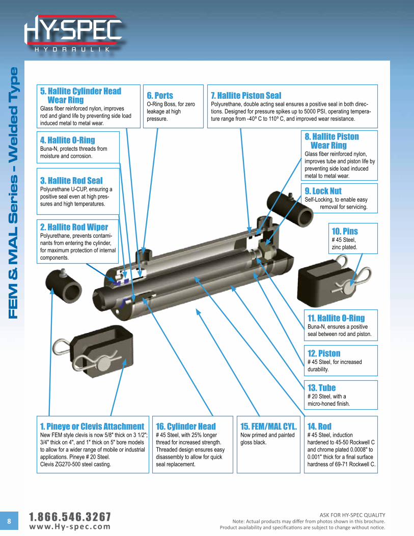
9. Lock NutSelf-Locking, to enable easy removal for servicing.
11. Hallite O-RingBuna-N, ensures a positive seal between rod and piston.
7. Hallite Piston SealPolyurethane, double acting seal ensures a positive seal in both direc-tions. Designed for pressure spikes up to 5000 PSI, operating tempera-ture range from -40º C to 110º C, and improved wear resistance.
8. Hallite Piston Wear RingGlass fiber reinforced nylon, improves tube and piston life by preventing side load induced metal to metal wear.
4. Hallite O-RingBuna-N, protects threads from moisture and corrosion.
5. Hallite Cylinder Head Wear RingGlass fiber reinforced nylon, improves rod and gland life by preventing side load induced metal to metal wear.
6. PortsO-Ring Boss, for zero leakage at high pressure.
1. Pineye or Clevis AttachmentNew FEM style clevis is now 5/8" thick on 3 1/2"; 3/4" thick on 4", and 1" thick on 5" bore models to allow for a wider range of mobile or industrial applications. Pineye # 20 Steel. Clevis ZG270-500 steel casting.
14. Rod# 45 Steel, induction hardened to 45-50 Rockwell C and chrome plated 0.0008" to 0.001" thick for a final surface hardness of 69-71 Rockwell C.
16. Cylinder Head# 45 Steel, with 25% longer thread for increased strength. Threaded design ensures easy disassembly to allow for quick seal replacement.
13. Tube# 20 Steel, with a micro-honed finish.
3. Hallite Rod SealPolyurethane U-CUP, ensuring a positive seal even at high pres-sures and high temperatures.
2. Hallite Rod WiperPolyurethane, prevents contami-nants from entering the cylinder, for maximum protection of internal components.
12. Piston# 45 Steel, for increased durability.
10. Pins# 45 Steel, zinc plated.
15. FEM/MAL CYL.Now primed and painted gloss black.
ASK FOR HY-SPEC QUALITYNote: Actual products may differ from photos shown in this brochure.Product availability and specifications are subject to change without notice.
1 . 8 6 6 . 5 4 6 . 3 2 6 7 www.Hy-spec.com 9
FE
M S
erie
s - W
eld
ed
Ty
pe
- Sp
ec
ifica
tion
s
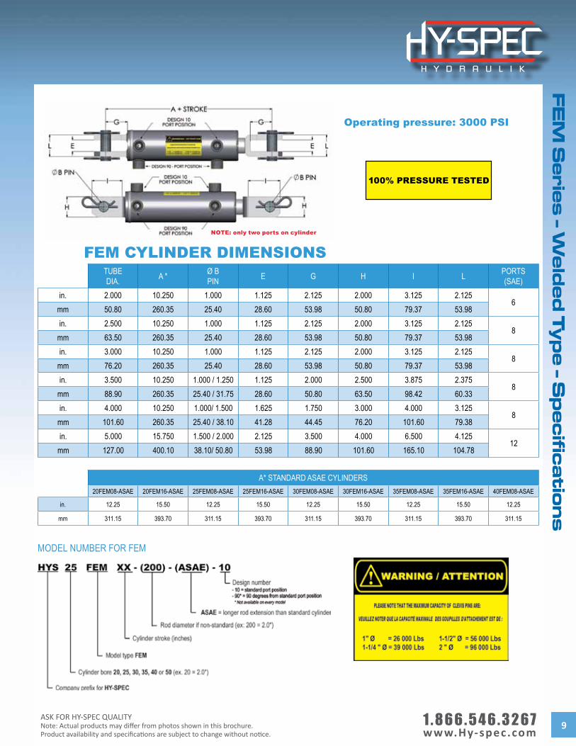
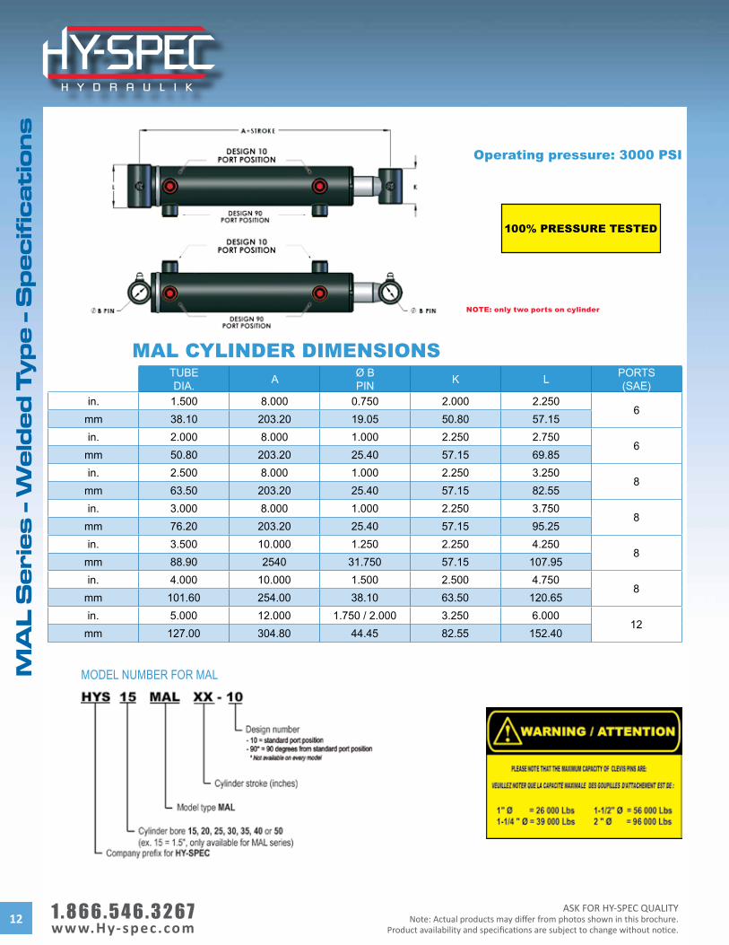
FEM CYLINDER DIMENSIONSTUBEDIA. A * Ø B
PIN E G H I L PORTS(SAE)
in. 2.000 10.250 1.000 1.125 2.125 2.000 3.125 2.1256
mm 50.80 260.35 25.40 28.60 53.98 50.80 79.37 53.98in. 2.500 10.250 1.000 1.125 2.125 2.000 3.125 2.125
8mm 63.50 260.35 25.40 28.60 53.98 50.80 79.37 53.98in. 3.000 10.250 1.000 1.125 2.125 2.000 3.125 2.125
8mm 76.20 260.35 25.40 28.60 53.98 50.80 79.37 53.98in. 3.500 10.250 1.000 / 1.250 1.125 2.000 2.500 3.875 2.375
8mm 88.90 260.35 25.40 / 31.75 28.60 50.80 63.50 98.42 60.33in. 4.000 10.250 1.000/ 1.500 1.625 1.750 3.000 4.000 3.125
8mm 101.60 260.35 25.40 / 38.10 41.28 44.45 76.20 101.60 79.38in. 5.000 15.750 1.500 / 2.000 2.125 3.500 4.000 6.500 4.125
12mm 127.00 400.10 38.10/ 50.80 53.98 88.90 101.60 165.10 104.78
A* STANDARD ASAE CYLINDERS20FEM08-ASAE 20FEM16-ASAE 25FEM08-ASAE 25FEM16-ASAE 30FEM08-ASAE 30FEM16-ASAE 35FEM08-ASAE 35FEM16-ASAE 40FEM08-ASAE
in. 12.25 15.50 12.25 15.50 12.25 15.50 12.25 15.50 12.25
mm 311.15 393.70 311.15 393.70 311.15 393.70 311.15 393.70 311.15
MODEL NUMBER FOR FEM
Operating pressure: 3000 PSI
100% PRESSURE TESTED
NOTE: only two ports on cylinder
1 . 8 6 6 . 5 4 6 . 3 2 6 7 www.Hy-spec.com
ASK FOR HY-SPEC QUALITYNote: Actual products may differ from photos shown in this brochure.
Product availability and specifications are subject to change without notice.10
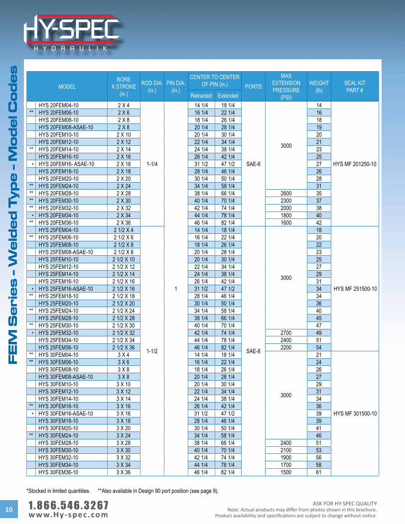
MODELBORE
X STROKE(in.)
ROD DIA.(in.)
PIN DIA. (in.)
CENTER TO CENTEROF PIN (in.) PORTS
MAXEXTENSION PRESSURE
(PSI)
WEIGHT(lb)
SEAL KITPART #
Retracted ExtendedHYS 20FEM04-10 2 X 4
1-1/4
1
14 1/4 18 1/4
SAE-6
3000
14
HYS MF 201250-10
** HYS 20FEM06-10 2 X 6 16 1/4 22 1/4 16HYS 20FEM08-10 2 X 8 18 1/4 26 1/4 18HYS 20FEM08-ASAE-10 2 X 8 20 1/4 28 1/4 19HYS 20FEM10-10 2 X 10 20 1/4 30 1/4 20HYS 20FEM12-10 2 X 12 22 1/4 34 1/4 21
** HYS 20FEM14-10 2 X 14 24 1/4 38 1/4 23HYS 20FEM16-10 2 X 16 26 1/4 42 1/4 25
* HYS 20FEM16- ASAE-10 2 X 16 31 1/2 47 1/2 27HYS 20FEM18-10 2 X 18 28 1/4 46 1/4 26HYS 20FEM20-10 2 X 20 30 1/4 50 1/4 28
** HYS 20FEM24-10 2 X 24 34 1/4 58 1/4 31** HYS 20FEM28-10 2 X 28 38 1/4 66 1/4 2600 35** HYS 20FEM30-10 2 X 30 40 1/4 70 1/4 2300 37** HYS 20FEM32-10 2 X 32 42 1/4 74 1/4 2000 38* HYS 20FEM34-10 2 X 34 44 1/4 78 1/4 1800 40
** HYS 20FEM36-10 2 X 36 46 1/4 82 1/4 1600 42HYS 25FEM04-10 2 1/2 X 4
1-1/2
14 1/4 18 1/4
SAE-8
3000
18
HYS MF 251500-10
** HYS 25FEM06-10 2 1/2 X 6 16 1/4 22 1/4 20HYS 25FEM08-10 2 1/2 X 8 18 1/4 26 1/4 22HYS 25FEM08-ASAE-10 2 1/2 X 8 20 1/4 28 1/4 23HYS 25FEM10-10 2 1/2 X 10 20 1/4 30 1/4 25HYS 25FEM12-10 2 1/2 X 12 22 1/4 34 1/4 27HYS 25FEM14-10 2 1/2 X 14 24 1/4 38 1/4 29HYS 25FEM16-10 2 1/2 X 16 26 1/4 42 1/4 31
* HYS 25FEM16-ASAE-10 2 1/2 X 16 31 1/2 47 1/2 34** HYS 25FEM18-10 2 1/2 X 18 28 1/4 46 1/4 34
HYS 25FEM20-10 2 1/2 X 20 30 1/4 50 1/4 36** HYS 25FEM24-10 2 1/2 X 24 34 1/4 58 1/4 40
HYS 25FEM28-10 2 1/2 X 28 38 1/4 66 1/4 45** HYS 25FEM30-10 2 1/2 X 30 40 1/4 70 1/4 47* HYS 25FEM32-10 2 1/2 X 32 42 1/4 74 1/4 2700 49
HYS 25FEM34-10 2 1/2 X 34 44 1/4 78 1/4 2400 51HYS 25FEM36-10 2 1/2 X 36 46 1/4 82 1/4 2200 54
** HYS 30FEM04-10 3 X 4 14 1/4 18 1/4
3000
21
HYS MF 301500-10
** HYS 30FEM06-10 3 X 6 16 1/4 22 1/4 24HYS 30FEM08-10 3 X 8 18 1/4 26 1/4 26HYS 30FEM08-ASAE-10 3 X 8 20 1/4 28 1/4 27HYS 30FEM10-10 3 X 10 20 1/4 30 1/4 29HYS 30FEM12-10 3 X 12 22 1/4 34 1/4 31HYS 30FEM14-10 3 X 14 24 1/4 38 1/4 34
** HYS 30FEM16-10 3 X 16 26 1/4 42 1/4 36* HYS 30FEM16-ASAE-10 3 X 16 31 1/2 47 1/2 39
HYS 30FEM18-10 3 X 18 28 1/4 46 1/4 39HYS 30FEM20-10 3 X 20 30 1/4 50 1/4 41
** HYS 30FEM24-10 3 X 24 34 1/4 58 1/4 46HYS 30FEM28-10 3 X 28 38 1/4 66 1/4 2400 51HYS 30FEM30-10 3 X 30 40 1/4 70 1/4 2100 53HYS 30FEM32-10 3 X 32 42 1/4 74 1/4 1900 56HYS 30FEM34-10 3 X 34 44 1/4 78 1/4 1700 58HYS 30FEM36-10 3 X 36 46 1/4 82 1/4 1500 61
*Stocked in limited quantities. **Also available in Design 90 port position (see page 9).
FE
M S
eri
es
- W
eld
ed
Ty
pe
- M
od
el C
od
es
ASK FOR HY-SPEC QUALITYNote: Actual products may differ from photos shown in this brochure.Product availability and specifications are subject to change without notice.
1 . 8 6 6 . 5 4 6 . 3 2 6 7 www.Hy-spec.com 11
FE
M S
erie
s - W
eld
ed
Ty
pe
- Mo
de
l Co
de
s
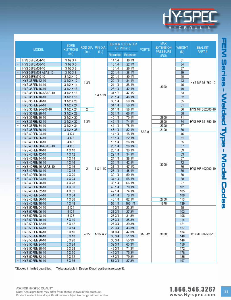
MODELBORE
X STROKE(in.)
ROD DIA.(in.)
PIN DIA. (in.)
CENTER TO CENTEROF PIN (in.) PORTS
MAXEXTENSION PRESSURE
(PSI)
WEIGHT(lb)
SEAL KITPART #
Retracted Extended
* HYS 35FEM04-10 3 1/2 X 4
1-3/4
1 & 1-1/4
14 1/4 18 1/4
SAE-8
3000
31
HYS MF 351750-10
* HYS 35FEM06-10 3 1/2 X 6 16 1/4 22 1/4 34HYS 35FEM08-10 3 1/2 X 8 18 1/4 26 1/4 37
* HYS 35FEM08-ASAE-10 3 1/2 X 8 20 1/4 28 1/4 39HYS 35FEM10-10 3 1/2 X 10 20 1/4 30 1/4 40HYS 35FEM12-10 3 1/2 X 12 22 1/4 34 1/4 43HYS 35FEM14-10 3 1/2 X 14 24 1/4 38 1/4 46HYS 35FEM16-10 3 1/2 X 16 26 1/4 42 1/4 49
* HYS 35FEM16-ASAE-10 3 1/2 X 16 31 1/2 47 1/2 53HYS 35FEM18-10 3 1/2 X 18 28 1/4 46 1/4 52HYS 35FEM20-10 3 1/2 X 20 30 1/4 50 1/4 55HYS 35FEM24-10 3 1/2 X 24 34 1/4 58 1/4 61HYS 35FEM24-200-10 3 1/2 X 24 2 34 1/4 58 1/4 66 HYS MF 352000-10 HYS 35FEM28-10 3 1/2 X 28
1-3/4
38 1/4 66 1/4 68
HYS MF 351750-10 * HYS 35FEM30-10 3 1/2 X 30 40 1/4 70 1/4 2900 71* HYS 35FEM32-10 3 1/2 X 32 42 1/4 74 1/4 2600 74* HYS 35FEM34-10 3 1/2 X 34 44 1/4 78 1/4 2300 77
HYS 35FEM36-10 3 1/2 X 36 46 1/4 82 1/4 2100 80HYS 40FEM04-10 4 X 4
2 1 & 1-1/2
14 1/4 18 1/4
3000
46
HYS MF 402000-10
HYS 40FEM06-10 4 X 6 16 1/4 22 1/4 51HYS 40FEM08-10 4 X 8 18 1/4 26 1/4 55
* HYS 40FEM08-ASAE-10 4 X 8 20 1/4 28 1/4 57HYS 40FEM10-10 4 X 10 20 1/4 30 1/4 59HYS 40FEM12-10 4 X 12 22 1/4 34 1/4 63HYS 40FEM14-10 4 X 14 24 1/4 38 1/4 67HYS 40FEM16-10 4 X 16 26 1/4 42 1/4 72
* HYS 40FEM16-ASAE-10 4 X 16 31 1/2 47 1/2 76HYS 40FEM18-10 4 X 18 28 1/4 46 1/4 76HYS 40FEM20-10 4 X 20 30 1/4 50 1/4 80
** HYS 40FEM24-10 4 X 24 34 1/4 58 1/4 88HYS 40FEM28-10 4 X 28 38 1/4 66 1/4 97HYS 40FEM30-10 4 X 30 40 1/4 70 1/4 101HYS 40FEM32-10 4 X 32 42 1/4 74 1/4 105
* HYS 40FEM34-10 4 X 34 44 1/4 78 1/4 109HYS 40FEM36-10 4 X 36 46 1/4 82 1/4 2700 113HYS 40FEM48-10 4 X 48 58 1/4 106 1/4 1670 139
* HYS 50FEM04-10 5 X 4
2-1/2 1-1/2 & 2
19 3/4 23 3/4
SAE-12 3000
95
HYS MF 502500-10
HYS 50FEM06-10 5 X 6 21 3/4 27 3/4 102HYS 50FEM08-10 5 X 8 23 3/4 31 3/4 108
* HYS 50FEM10-10 5 X 10 25 3/4 35 3/4 114HYS 50FEM12-10 5 X 12 27 3/4 39 3/4 121
* HYS 50FEM14-10 5 X 14 29 3/4 43 3/4 127* HYS 50FEM16-10 5 X 16 31 3/4 47 3/4 134
HYS 50FEM18-10 5 X 18 33 3/4 51 3/4 140HYS 50FEM20-10 5 X 20 35 3/4 55 3/4 146HYS 50FEM24-10 5 X 24 39 3/4 63 3/4 159HYS 50FEM28-10 5 X 28 43 3/4 71 3/4 172HYS 50FEM30-10 5 X 30 45 3/4 75 3/4 178HYS 50FEM32-10 5 X 32 47 3/4 79 3/4 185
* HYS 50FEM36-10 5 X 36 51 3/4 87 3/4 197
*Stocked in limited quantities. **Also available in Design 90 port position (see page 9).
1 . 8 6 6 . 5 4 6 . 3 2 6 7 www.Hy-spec.com
ASK FOR HY-SPEC QUALITYNote: Actual products may differ from photos shown in this brochure.
Product availability and specifications are subject to change without notice.12
TUBEDIA. A Ø B
PIN K L PORTS(SAE)
in. 1.500 8.000 0.750 2.000 2.2506
mm 38.10 203.20 19.05 50.80 57.15in. 2.000 8.000 1.000 2.250 2.750
6mm 50.80 203.20 25.40 57.15 69.85in. 2.500 8.000 1.000 2.250 3.250
8mm 63.50 203.20 25.40 57.15 82.55in. 3.000 8.000 1.000 2.250 3.750
8mm 76.20 203.20 25.40 57.15 95.25in. 3.500 10.000 1.250 2.250 4.250
8mm 88.90 2540 31.750 57.15 107.95in. 4.000 10.000 1.500 2.500 4.750
8mm 101.60 254.00 38.10 63.50 120.65in. 5.000 12.000 1.750 / 2.000 3.250 6.000
12mm 127.00 304.80 44.45 82.55 152.40
MAL CYLINDER DIMENSIONS
MODEL NUMBER FOR MAL
Operating pressure: 3000 PSI
100% PRESSURE TESTED
MA
L S
eri
es
- W
eld
ed
Ty
pe
- S
pe
cif
ica
tio
ns
NOTE: only two ports on cylinder
ASK FOR HY-SPEC QUALITYNote: Actual products may differ from photos shown in this brochure.Product availability and specifications are subject to change without notice.
1 . 8 6 6 . 5 4 6 . 3 2 6 7 www.Hy-spec.com 13
MA
L S
erie
s - W
eld
ed
Ty
pe
- Mo
de
l Co
de
s
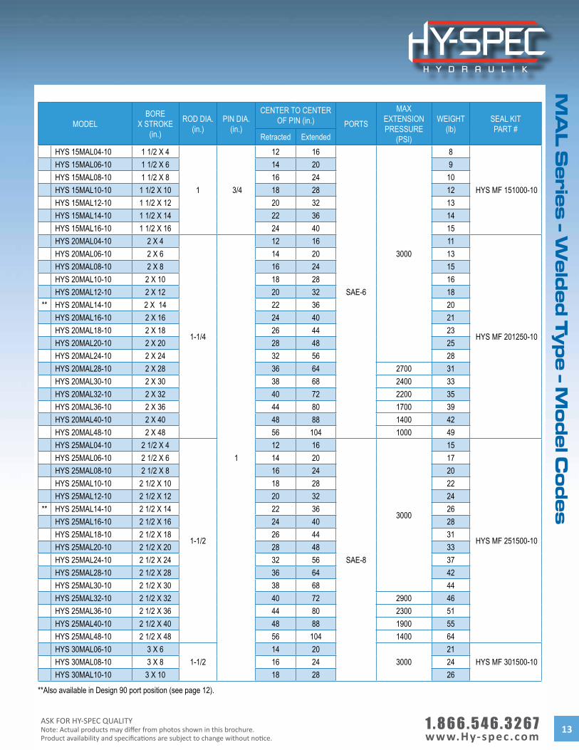
MODELBORE
X STROKE(in.)
ROD DIA.(in.)
PIN DIA.(in.)
CENTER TO CENTER OF PIN (in.) PORTS
MAXEXTENSION PRESSURE
(PSI)
WEIGHT(lb)
SEAL KITPART #
Retracted Extended
HYS 15MAL04-10 1 1/2 X 4
1 3/4
12 16
SAE-6
3000
8
HYS MF 151000-10
HYS 15MAL06-10 1 1/2 X 6 14 20 9HYS 15MAL08-10 1 1/2 X 8 16 24 10HYS 15MAL10-10 1 1/2 X 10 18 28 12HYS 15MAL12-10 1 1/2 X 12 20 32 13HYS 15MAL14-10 1 1/2 X 14 22 36 14HYS 15MAL16-10 1 1/2 X 16 24 40 15HYS 20MAL04-10 2 X 4
1-1/4
1
12 16 11
HYS MF 201250-10
HYS 20MAL06-10 2 X 6 14 20 13HYS 20MAL08-10 2 X 8 16 24 15HYS 20MAL10-10 2 X 10 18 28 16HYS 20MAL12-10 2 X 12 20 32 18
** HYS 20MAL14-10 2 X 14 22 36 20HYS 20MAL16-10 2 X 16 24 40 21HYS 20MAL18-10 2 X 18 26 44 23HYS 20MAL20-10 2 X 20 28 48 25HYS 20MAL24-10 2 X 24 32 56 28HYS 20MAL28-10 2 X 28 36 64 2700 31HYS 20MAL30-10 2 X 30 38 68 2400 33HYS 20MAL32-10 2 X 32 40 72 2200 35HYS 20MAL36-10 2 X 36 44 80 1700 39HYS 20MAL40-10 2 X 40 48 88 1400 42HYS 20MAL48-10 2 X 48 56 104 1000 49HYS 25MAL04-10 2 1/2 X 4
1-1/2
12 16
SAE-8
3000
15
HYS MF 251500-10
HYS 25MAL06-10 2 1/2 X 6 14 20 17HYS 25MAL08-10 2 1/2 X 8 16 24 20HYS 25MAL10-10 2 1/2 X 10 18 28 22HYS 25MAL12-10 2 1/2 X 12 20 32 24
** HYS 25MAL14-10 2 1/2 X 14 22 36 26HYS 25MAL16-10 2 1/2 X 16 24 40 28HYS 25MAL18-10 2 1/2 X 18 26 44 31HYS 25MAL20-10 2 1/2 X 20 28 48 33HYS 25MAL24-10 2 1/2 X 24 32 56 37HYS 25MAL28-10 2 1/2 X 28 36 64 42HYS 25MAL30-10 2 1/2 X 30 38 68 44HYS 25MAL32-10 2 1/2 X 32 40 72 2900 46HYS 25MAL36-10 2 1/2 X 36 44 80 2300 51HYS 25MAL40-10 2 1/2 X 40 48 88 1900 55HYS 25MAL48-10 2 1/2 X 48 56 104 1400 64HYS 30MAL06-10 3 X 6
1-1/214 20
300021
HYS MF 301500-10 HYS 30MAL08-10 3 X 8 16 24 24HYS 30MAL10-10 3 X 10 18 28 26
**Also available in Design 90 port position (see page 12).
1 . 8 6 6 . 5 4 6 . 3 2 6 7 www.Hy-spec.com
ASK FOR HY-SPEC QUALITYNote: Actual products may differ from photos shown in this brochure.
Product availability and specifications are subject to change without notice.14
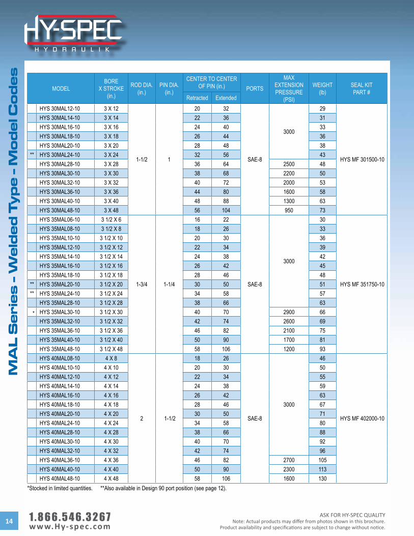
MODELBORE
X STROKE(in.)
ROD DIA.(in.)
PIN DIA.(in.)
CENTER TO CENTER OF PIN (in.) PORTS
MAXEXTENSION PRESSURE
(PSI)
WEIGHT(lb)
SEAL KITPART #
Retracted Extended
HYS 30MAL12-10 3 X 12
1-1/2 1
20 32
SAE-8
3000
29
HYS MF 301500-10
HYS 30MAL14-10 3 X 14 22 36 31HYS 30MAL16-10 3 X 16 24 40 33HYS 30MAL18-10 3 X 18 26 44 36HYS 30MAL20-10 3 X 20 28 48 38
** HYS 30MAL24-10 3 X 24 32 56 43HYS 30MAL28-10 3 X 28 36 64 2500 48HYS 30MAL30-10 3 X 30 38 68 2200 50HYS 30MAL32-10 3 X 32 40 72 2000 53HYS 30MAL36-10 3 X 36 44 80 1600 58HYS 30MAL40-10 3 X 40 48 88 1300 63HYS 30MAL48-10 3 X 48 56 104 950 73HYS 35MAL06-10 3 1/2 X 6
1-3/4 1-1/4
16 22
SAE-8
3000
30
HYS MF 351750-10
HYS 35MAL08-10 3 1/2 X 8 18 26 33HYS 35MAL10-10 3 1/2 X 10 20 30 36HYS 35MAL12-10 3 1/2 X 12 22 34 39HYS 35MAL14-10 3 1/2 X 14 24 38 42HYS 35MAL16-10 3 1/2 X 16 26 42 45HYS 35MAL18-10 3 1/2 X 18 28 46 48
** HYS 35MAL20-10 3 1/2 X 20 30 50 51** HYS 35MAL24-10 3 1/2 X 24 34 58 57
HYS 35MAL28-10 3 1/2 X 28 38 66 63* HYS 35MAL30-10 3 1/2 X 30 40 70 2900 66
HYS 35MAL32-10 3 1/2 X 32 42 74 2600 69HYS 35MAL36-10 3 1/2 X 36 46 82 2100 75HYS 35MAL40-10 3 1/2 X 40 50 90 1700 81HYS 35MAL48-10 3 1/2 X 48 58 106 1200 93HYS 40MAL08-10 4 X 8
2 1-1/2
18 26
SAE-8
3000
46
HYS MF 402000-10
HYS 40MAL10-10 4 X 10 20 30 50HYS 40MAL12-10 4 X 12 22 34 55HYS 40MAL14-10 4 X 14 24 38 59HYS 40MAL16-10 4 X 16 26 42 63HYS 40MAL18-10 4 X 18 28 46 67HYS 40MAL20-10 4 X 20 30 50 71HYS 40MAL24-10 4 X 24 34 58 80HYS 40MAL28-10 4 X 28 38 66 88HYS 40MAL30-10 4 X 30 40 70 92HYS 40MAL32-10 4 X 32 42 74 96HYS 40MAL36-10 4 X 36 46 82 2700 105HYS 40MAL40-10 4 X 40 50 90 2300 113HYS 40MAL48-10 4 X 48 58 106 1600 130
*Stocked in limited quantities. **Also available in Design 90 port position (see page 12).
MA
L S
eri
es
- W
eld
ed
Ty
pe
- M
od
el C
od
es
ASK FOR HY-SPEC QUALITYNote: Actual products may differ from photos shown in this brochure.Product availability and specifications are subject to change without notice.
1 . 8 6 6 . 5 4 6 . 3 2 6 7 www.Hy-spec.com 15
Pa
rts &
Ac
ce
ss
orie
s
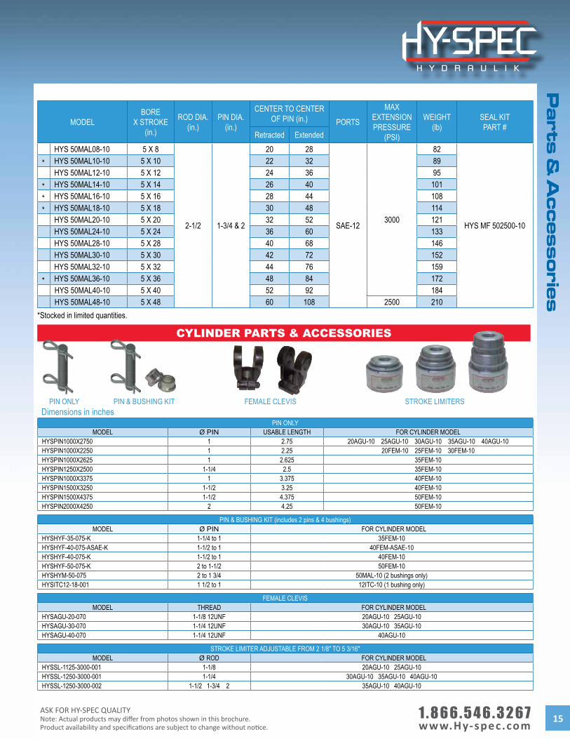
MODELBORE
X STROKE(in.)
ROD DIA.(in.)
PIN DIA.(in.)
CENTER TO CENTER OF PIN (in.) PORTS
MAXEXTENSION PRESSURE
(PSI)
WEIGHT(lb)
SEAL KITPART #
Retracted ExtendedHYS 50MAL08-10 5 X 8
2-1/2 1-3/4 & 2
20 28
SAE-123000
82
HYS MF 502500-10
* HYS 50MAL10-10 5 X 10 22 32 89HYS 50MAL12-10 5 X 12 24 36 95
* HYS 50MAL14-10 5 X 14 26 40 101* HYS 50MAL16-10 5 X 16 28 44 108* HYS 50MAL18-10 5 X 18 30 48 114
HYS 50MAL20-10 5 X 20 32 52 121HYS 50MAL24-10 5 X 24 36 60 133HYS 50MAL28-10 5 X 28 40 68 146HYS 50MAL30-10 5 X 30 42 72 152HYS 50MAL32-10 5 X 32 44 76 159
* HYS 50MAL36-10 5 X 36 48 84 172HYS 50MAL40-10 5 X 40 52 92 184HYS 50MAL48-10 5 X 48 60 108 2500 210
CYLINDER PARTS & ACCESSORIES
PIN & BUSHING KIT
PIN ONLYMODEL Ø PIN USABLE LENGTH FOR CYLINDER MODEL
HYSPIN1000X2750 1 2.75 20AGU-10 25AGU-10 30AGU-10 35AGU-10 40AGU-10HYSPIN1000X2250 1 2.25 20FEM-10 25FEM-10 30FEM-10HYSPIN1000X2625 1 2.625 35FEM-10HYSPIN1250X2500 1-1/4 2.5 35FEM-10HYSPIN1000X3375 1 3.375 40FEM-10HYSPIN1500X3250 1-1/2 3.25 40FEM-10HYSPIN1500X4375 1-1/2 4.375 50FEM-10HYSPIN2000X4250 2 4.25 50FEM-10
PIN & BUSHING KIT (includes 2 pins & 4 bushings)MODEL Ø PIN FOR CYLINDER MODEL
HYSHYF-35-075-K 1-1/4 to 1 35FEM-10HYSHYF-40-075-ASAE-K 1-1/2 to 1 40FEM-ASAE-10HYSHYF-40-075-K 1-1/2 to 1 40FEM-10HYSHYF-50-075-K 2 to 1-1/2 50FEM-10HYSHYM-50-075 2 to 1 3/4 50MAL-10 (2 bushings only)HYSITC12-18-001 1 1/2 to 1 12ITC-10 (1 bushing only)
FEMALE CLEVISMODEL THREAD FOR CYLINDER MODEL
HYSAGU-20-070 1-1/8 12UNF 20AGU-10 25AGU-10HYSAGU-30-070 1-1/4 12UNF 30AGU-10 35AGU-10HYSAGU-40-070 1-1/4 12UNF 40AGU-10
STROKE LIMITER ADJUSTABLE FROM 2 1/8" TO 5 3/16"MODEL Ø ROD FOR CYLINDER MODEL
HYSSL-1125-3000-001 1-1/8 20AGU-10 25AGU-10HYSSL-1250-3000-001 1-1/4 30AGU-10 35AGU-10 40AGU-10HYSSL-1250-3000-002 1-1/2 1-3/4 2 35AGU-10 40AGU-10
Dimensions in inches
*Stocked in limited quantities.
STROKE LIMITERSFEMALE CLEVISPIN ONLY
1 . 8 6 6 . 5 4 6 . 3 2 6 7 www.Hy-spec.com
ASK FOR HY-SPEC QUALITYNote: Actual products may differ from photos shown in this brochure.
Product availability and specifications are subject to change without notice.16
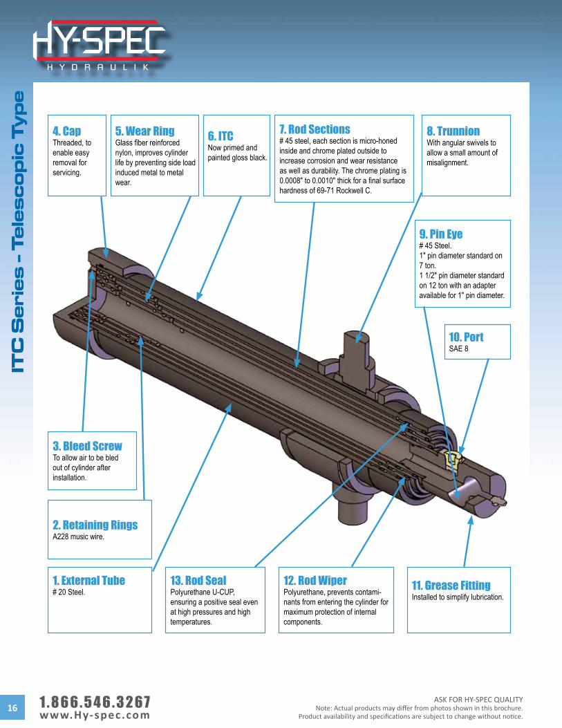
8. TrunnionWith angular swivels to allow a small amount of misalignment.
7. Rod Sections# 45 steel, each section is micro-honed inside and chrome plated outside to increase corrosion and wear resistance as well as durability. The chrome plating is 0.0008" to 0.0010" thick for a final surface hardness of 69-71 Rockwell C.
5. Wear RingGlass fiber reinforced nylon, improves cylinder life by preventing side load induced metal to metal wear.
9. Pin Eye# 45 Steel.1" pin diameter standard on 7 ton.1 1/2" pin diameter standard on 12 ton with an adapter available for 1" pin diameter.
3. Bleed ScrewTo allow air to be bled out of cylinder after installation.
2. Retaining RingsA228 music wire.
1. External Tube# 20 Steel.
13. Rod SealPolyurethane U-CUP, ensuring a positive seal even at high pressures and high temperatures.
12. Rod WiperPolyurethane, prevents contami-nants from entering the cylinder for maximum protection of internal components.
11. Grease FittingInstalled to simplify lubrication.
4. CapThreaded, to enable easy removal for servicing.
10. PortSAE 8
6. ITCNow primed and painted gloss black.
ITC
Se
rie
s -
Te
les
co
pic
Ty
pe
ASK FOR HY-SPEC QUALITYNote: Actual products may differ from photos shown in this brochure.Product availability and specifications are subject to change without notice.
1 . 8 6 6 . 5 4 6 . 3 2 6 7 www.Hy-spec.com 17
ITC
Se
ries
- Te
les
co
pic
Ty
pe
- Mo
de
l Co
de
s
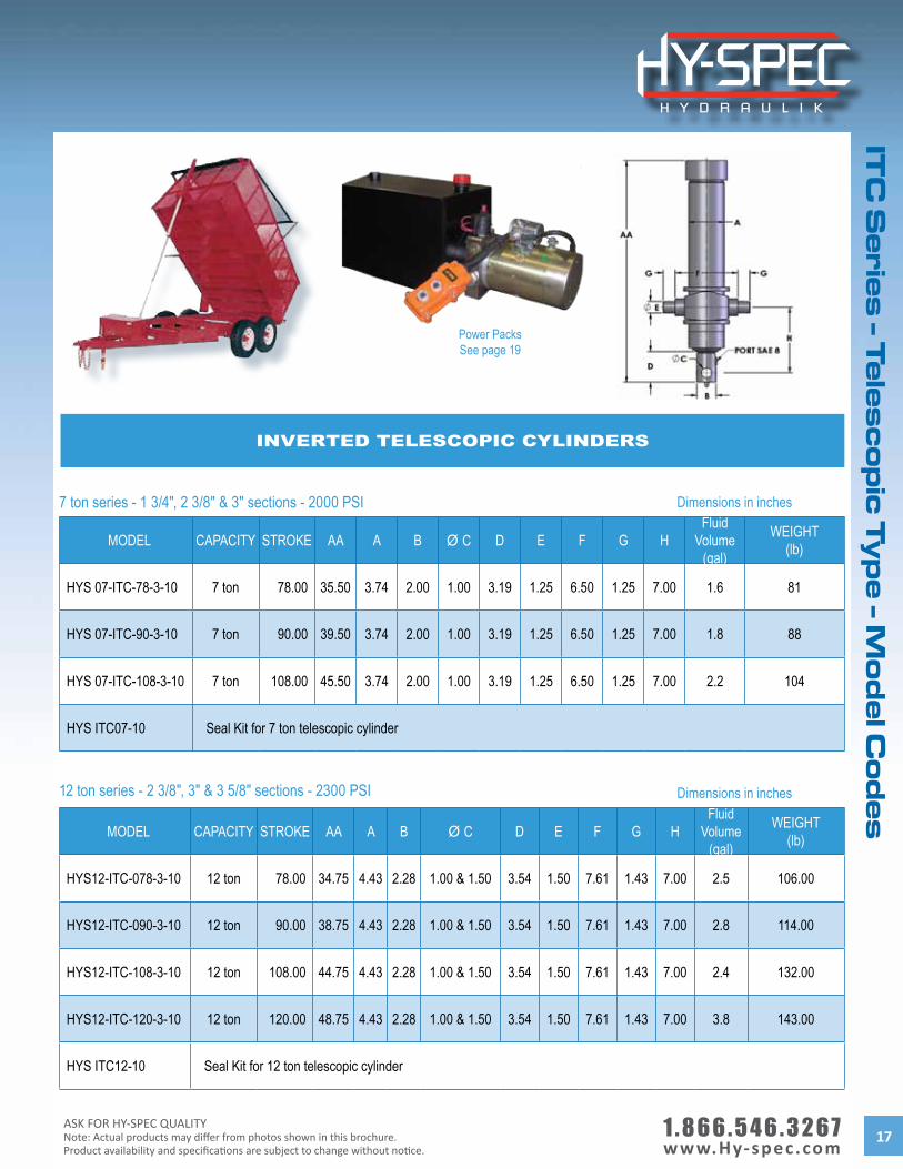
MODEL CAPACITY STROKE AA A B Ø C D E F G HFluid
Volume(gal)
WEIGHT(lb)
HYS 07-ITC-78-3-10 7 ton 78.00 35.50 3.74 2.00 1.00 3.19 1.25 6.50 1.25 7.00 1.6 81
HYS 07-ITC-90-3-10 7 ton 90.00 39.50 3.74 2.00 1.00 3.19 1.25 6.50 1.25 7.00 1.8 88
HYS 07-ITC-108-3-10 7 ton 108.00 45.50 3.74 2.00 1.00 3.19 1.25 6.50 1.25 7.00 2.2 104
HYS ITC07-10 Seal Kit for 7 ton telescopic cylinder
MODEL CAPACITY STROKE AA A B Ø C D E F G HFluid
Volume(gal)
WEIGHT(lb)
HYS12-ITC-078-3-10 12 ton 78.00 34.75 4.43 2.28 1.00 & 1.50 3.54 1.50 7.61 1.43 7.00 2.5 106.00
HYS12-ITC-090-3-10 12 ton 90.00 38.75 4.43 2.28 1.00 & 1.50 3.54 1.50 7.61 1.43 7.00 2.8 114.00
HYS12-ITC-108-3-10 12 ton 108.00 44.75 4.43 2.28 1.00 & 1.50 3.54 1.50 7.61 1.43 7.00 2.4 132.00
HYS12-ITC-120-3-10 12 ton 120.00 48.75 4.43 2.28 1.00 & 1.50 3.54 1.50 7.61 1.43 7.00 3.8 143.00
HYS ITC12-10 Seal Kit for 12 ton telescopic cylinder
INVERTED TELESCOPIC CYLINDERS
7 ton series - 1 3/4", 2 3/8" & 3" sections - 2000 PSI Dimensions in inches
Dimensions in inches12 ton series - 2 3/8", 3" & 3 5/8" sections - 2300 PSI
Power PacksSee page 19
1 . 8 6 6 . 5 4 6 . 3 2 6 7 www.Hy-spec.com
ASK FOR HY-SPEC QUALITYNote: Actual products may differ from photos shown in this brochure.
Product availability and specifications are subject to change without notice.18
THE MAXIMUM ANGLE ALLOWED IS 50°
MODEL X Y X Y X Y
HYS07-ITC-078-3-10 9’ 2" 42° 8’ 6" 45° 8’ 2" 47°HYS07-ITC-090-3-10 10’ 44° 9’ 6" 46° 9’ 49°HYS07-ITC-108-3-10 12’ 44° 11’ 6" 46° 11’ 48°HYS12-ITC-078-3-10 9’ 2" 42° 8’ 6" 45° 8’ 2" 47°HYS12-ITC-090-3-10 10’ 44° 9’ 6" 46° 9’ 49°HYS12-ITC-108-3-10 12’ 44° 11’ 6" 46° 11’ 48°HYS12-ITC-120-3-10 13’ 45° 12’ 6" 47° 12’ 49°
Overhang
Dump angleY
Cylinder base mounting pin to box hinge pinX
ITC TELESCOPIC CYLINDERS - DUMP ANGLE
PART # DESCRIPTION
HYS 712-ITS-000-10 Frame bracket for 7 ton and 12 ton cylinderHYS 007-ITS-000-10 Box bracket for 7 ton cylinder (2 required per cylinder)HYS 012-ITS-000-10 Box bracket for 12 ton cylinder (2 required per cylinder)
FRAME AND BOX BRACKETS7 TON & 12 TON
Box bracket Frame bracket
ITC
Se
rie
s -
Te
les
co
pic
Ty
pe
- F
ram
e a
nd
Bo
x B
rac
ke
ts
ASK FOR HY-SPEC QUALITYNote: Actual products may differ from photos shown in this brochure.Product availability and specifications are subject to change without notice.
1 . 8 6 6 . 5 4 6 . 3 2 6 7 www.Hy-spec.com 19
Po
we
r Pa
ck
s
POwEr PaCkS fOr TraILEr aPPLICaTIOnMODEL DESCRIPTION
HYSSE12H3GSMOR23-R2 Dump trailer power pack - 7 ton
HYSSE12H5GSMOR23-R2 Dump trailer power pack - 12 ton
HYSLSV2-08-2NCP-M-ID 2 position - 2 way cartridge valve with manual override
Emergency manualoverride feature
7 3/4"
8 1/8"
7 ton = 22"12 ton = 31"
WIRELESS REMOTE CONTROLMODEL DESCRIPTION OPERATING VOLTAGE MAXIMUM CURRENT OPERATING TEMPERATUREHYS GS-HYD-D7 Wireless remote control +9 V DC to +28V DC 10 Amps DC Max -40°C to +125°C
POWER PACK FOR SNOWPLOW
MODEL DESCRIPTION
HYS YBZ-F2.1S1W14/WUAAT1 Snow plow power pack
Features and Benefits• Can handle 12 or 24 volt DC• Potted for protection• Installation wires instead of terminals• Learning transmitter• 3-minute automatic time-out feature• In-line fuse already installed• Back-up manual switches on receiver• On/off switch on transmitter and receiver• Can still use the tethered remote
Note: For more power pack models and options, please refer to our AC/DC power packs catalogue
1 . 8 6 6 . 5 4 6 . 3 2 6 7 www.Hy-spec.com
ASK FOR HY-SPEC QUALITYNote: Actual products may differ from photos shown in this brochure.
Product availability and specifications are subject to change without notice.20
Sn
ow
Plo
ws
- M
od
el C
od
es
MODEL BORE X STROKE
Ø A PIN B C WEIGHT
(lb) Fisher Replacement HYS F-SP-150-10-1000 1 1/2 X 10 1.000 18.750 20.500 15 HYS F-SP-150-12-1000 1 1/2 X 12 1.000 20.750 22.500 16 Meyer Replacement HYS M-SP-150-06-0625 1 1/2 X 6.375 0.625 12.000 13.375 10 HYS M-SP-150-10-0625 1 1/2 X 10.375 0.625 16.063 17.500 14 HYS M-SP-150-12-0625 1 1/2 X 12 0.625 18.000 19.375 15 HYS M-SP-200-06-0750 2 X 6 0.750 13.188 14.688 17 HYS M-SP-200-12-0625 2 X 12 0.625 18.000 19.375 24 Western Replacement HYS W-SP-150-06-0750 1 1/2 X 6.063 0.750 12.937 14.313 11 HYS W-SP-150-08-0750 1 1/2 X 8 0.750 15.250 16.625 12 HYS W-SP-150-10-0750 1 1/2 X 10 0.750 17.250 18.625 14 HYS-W-SP-150-10-1000 1 1/2 X 10 1.000 17.000 18.500 14 HYS-W-SP-200-10-1000 2 X 10 1.000 17.250 18.750 22 HYS W-SP-200-16-1000 2 X 16.375 1.000 23.625 25.125 31 Monarch Replacement HYS MN-SP-150-10-1000 1 1/2 X 10 1.000 17.000 18.625 14 HYS MN-SP-150-12-1000 1 1/2 X 12 1.000 19.000 20.625 15 Artic Replacement HYS A-SP-150-10-0750 1 1/2 X 10 0.750 17.000 18.500 14 HYS A-SP-150-12-0750 1 1/2 X 12 0.750 19.000 20.500 16
Dimensions in inches
MODEL NUMBER FOR SP
ASK FOR HY-SPEC QUALITYNote: Actual products may differ from photos shown in this brochure.Product availability and specifications are subject to change without notice.
1 . 8 6 6 . 5 4 6 . 3 2 6 7 www.Hy-spec.com 21
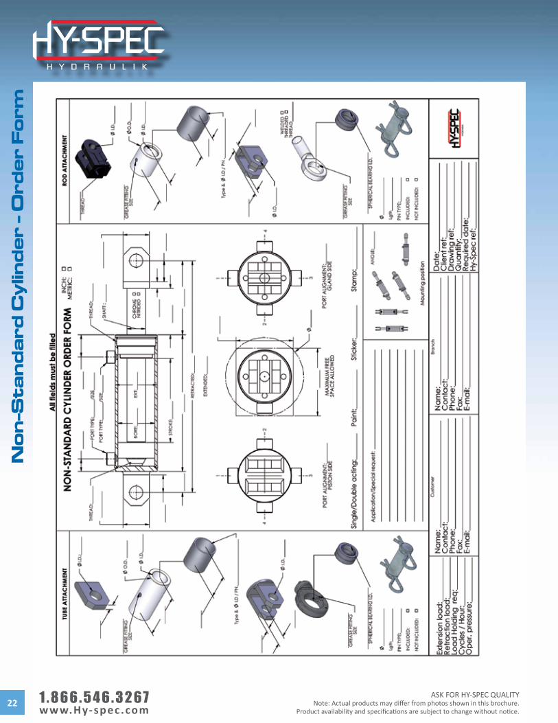
SPECIAL CYLINDER REQUIREMENTS
Contact us for all of your special cylinder requirements!Order form available (next page)
• By-passmanifolds• Cartridgevalvecavities• Moldedattachments• Multipleports• Nitratedshafts
• Porttubes• Rephasingcylinders• Singleacting• Specialattachments• Specialheads
• Specialmanifolds• Specialrodends• Sphericalrodends• Trunnionmounts
No
n-S
tan
da
rd C
ylin
de
rs
1 . 8 6 6 . 5 4 6 . 3 2 6 7 www.Hy-spec.com
ASK FOR HY-SPEC QUALITYNote: Actual products may differ from photos shown in this brochure.
Product availability and specifications are subject to change without notice.22
No
n-S
tan
da
rd C
ylin
de
r -
Ord
er
Fo
rm
ASK FOR HY-SPEC QUALITYNote: Actual products may differ from photos shown in this brochure.Product availability and specifications are subject to change without notice.
1 . 8 6 6 . 5 4 6 . 3 2 6 7 www.Hy-spec.com 23
NO
N-S
TAN
DA
RD
CY
LIN
DE
RS
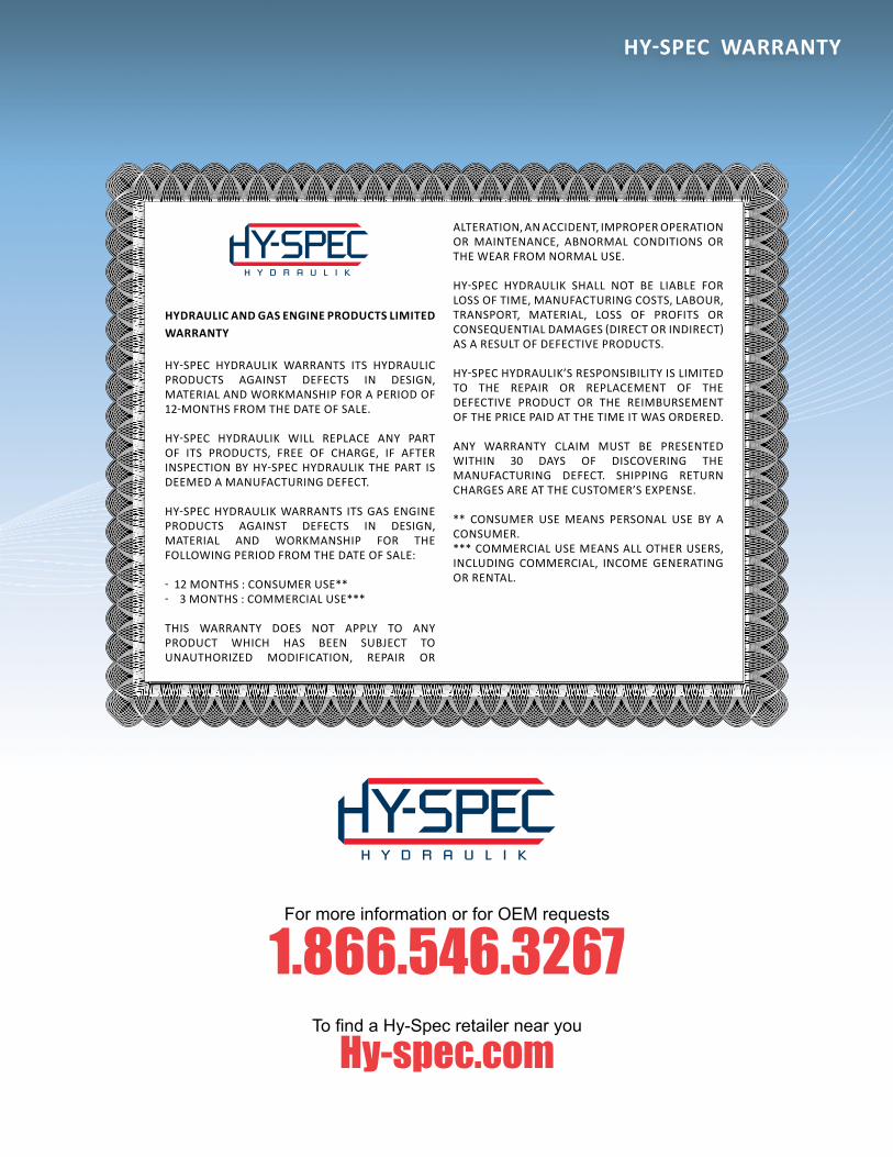
HYDRAULIC AND GAS ENGINE PRODUCTS LIMITED WARRANTY
HY-SPEC HYDRAULIK WARRANTS ITS HYDRAULIC PRODUCTS AGAINST DEFECTS IN DESIGN, MATERIAL AND WORKMANSHIP FOR A PERIOD OF 12-MONTHS FROM THE DATE OF SALE.
HY-SPEC HYDRAULIK WILL REPLACE ANY PART OF ITS PRODUCTS, FREE OF CHARGE, IF AFTER INSPECTION BY HY-SPEC HYDRAULIK THE PART IS DEEMED A MANUFACTURING DEFECT.
HY-SPEC HYDRAULIK WARRANTS ITS GAS ENGINE PRODUCTS AGAINST DEFECTS IN DESIGN, MATERIAL AND WORKMANSHIP FOR THE FOLLOWING PERIOD FROM THE DATE OF SALE:
- 12 MONTHS : CONSUMER USE**- 3 MONTHS : COMMERCIAL USE***
THIS WARRANTY DOES NOT APPLY TO ANY PRODUCT WHICH HAS BEEN SUBJECT TO UNAUTHORIZED MODIFICATION, REPAIR OR
ALTERATION, AN ACCIDENT, IMPROPER OPERATION OR MAINTENANCE, ABNORMAL CONDITIONS OR THE WEAR FROM NORMAL USE.
HY-SPEC HYDRAULIK SHALL NOT BE LIABLE FOR LOSS OF TIME, MANUFACTURING COSTS, LABOUR, TRANSPORT, MATERIAL, LOSS OF PROFITS OR CONSEQUENTIAL DAMAGES (DIRECT OR INDIRECT) AS A RESULT OF DEFECTIVE PRODUCTS.
HY-SPEC HYDRAULIK’S RESPONSIBILITY IS LIMITED TO THE REPAIR OR REPLACEMENT OF THE DEFECTIVE PRODUCT OR THE REIMBURSEMENT OF THE PRICE PAID AT THE TIME IT WAS ORDERED.
ANY WARRANTY CLAIM MUST BE PRESENTED WITHIN 30 DAYS OF DISCOVERING THE MANUFACTURING DEFECT. SHIPPING RETURN CHARGES ARE AT THE CUSTOMER’S EXPENSE.
** CONSUMER USE MEANS PERSONAL USE BY A CONSUMER.*** COMMERCIAL USE MEANS ALL OTHER USERS, INCLUDING COMMERCIAL, INCOME GENERATING OR RENTAL.
HY-SPEC WARRANTY
For more information or for OEM requests
1.866.546.3267To fi nd a Hy-Spec retailer near you
Hy-spec.com
WIC-EN-CATALOGUES-COVERS-2012-DYNAMIC-16.indd 3 2014-06-04 15:14:33

Your distributor
HY-SPEC CATALOGUE - HYDRAULIC CYLINDERS
HY-SPEC-CATALOGUE-HYDRAULIC-CYLINDERS-2-05-2014HY-SPEC IS A WAJAX INDUSTRIAL COMPONENTS BRAND.
HY-SPEC HYDRAULIK specializes in the import and export of a wide range of high quality hydraulic components such as: agricultural, telescopic and uti lity cylinders; directi onal control valves; gas engines; power packs and much more.
The HY-SPEC brand name stands for high quality hydraulic components. These products are manufactured around the world to our high specifi cati ons, which are established by our engineering department.
The HY-SPEC team members have been chosen for their experience and are trained to give professional and effi cient service, which you can depend on. Their experience totals over 100 years in the hydraulic industry. They work closely with our customers to provide the best soluti on for their applicati on.
Hydraulic Cylinders
Typical Equipment
Fork Lift s Loaders Presses Tractors
Typical Industries
Agriculture Constructi on Forestry Mining
WIC-EN-CATALOGUES-COVERS-2012-DYNAMIC-16.indd 16 2014-05-02 16:32:36