hydraulic cylinders heavy-duty large bore tie rod type€¦ · · 2016-01-16hydraulic cylinders...
TRANSCRIPT

Hydraulic CylindersHeavy-Duty Large Bore Tie Rod TypeCatalog
Series HG

2 EATON Hydro-Line Large Bore Cylinder Catalog H-CYTR-MC001-E August 2007
Table of Contents
Design Features ........................................................................................................................................................................3
Model Code ..............................................................................................................................................................................4
How to Order ............................................................................................................................................................................6
Mounting Style & Installation Dimensions ..........................................................................................................................7
Mounting Application Guide ......................................................................................................................................7
HG KS Basic Cylinder - No Mount ............................................................................................................................9
HG AS Side Lug Mount ............................................................................................................................................10
HG JS Head Square Mount ......................................................................................................................................12
HG GS Head Rectangular Mount ............................................................................................................................14
HG CF Cap Clevis Mount ..........................................................................................................................................16
HG SS Cap Square Mount ........................................................................................................................................18
HG PS Cap Rectangular Mount ................................................................................................................................20
HG TT Intermediate Trunnion Mount........................................................................................................................22
HG WS Cap Trunnion Mount ....................................................................................................................................24
HG US Head Trunnion Mount ..................................................................................................................................26
HG HS Centerline Lug Mount ..................................................................................................................................28
HG NS Cap End Extended Tie Rod Mount ..............................................................................................................30
HG MS Head End Extended Tie Rod Mount............................................................................................................32
HG LS Both Ends Extended Tie Rod Mount ............................................................................................................34
HG Double Rod End ..................................................................................................................................................36
Common Options ..................................................................................................................................................................37
Port Options ..............................................................................................................................................................37
Rod End Selection ....................................................................................................................................................38
Sealing Option ..........................................................................................................................................................39
Port and Cushion Selection ......................................................................................................................................40
Mounting Accessories............................................................................................................................................................41
Mounting Accessories ..............................................................................................................................................41
Self Aligning Coupler ................................................................................................................................................42
Grooved Rod End Coupling......................................................................................................................................43
Application/Engineering Data ..............................................................................................................................................44
Stop Tube Selection ..................................................................................................................................................44
Tie Rod Spacer Selection..........................................................................................................................................45
PS200 Proximity Switch ............................................................................................................................................46
Limit Switch................................................................................................................................................................47
Tie Rod Information ..................................................................................................................................................48
Buckling Chart ............................................................................................................................................................49

3EATON Hydro-Line Large Bore Cylinder Catalog H-CYTR-MC001-E August 2007
Design Features
A. Heavy Duty Bolt-on Rod Cartridge
• Nitrided, bolt-on rod cartridge is pilot-fitted intothe head and incorporatesan outboard bearingdesign for maximum rodsupport and long life.
B. Rod Sealing System
• The normal high durometer, mechanically energized rod seal with adouble lip rod wiper provides contaminationexclusion and abrasionresistance to deliverexceptional performanceand durability.
• Low friction and high temperature rod sealingsystems are also availableoptions.
• Metallic rod scraper is anavailable option for toughenvironmental conditions.
C. Secured Piston
• One piece, pilot-fitted,ductile iron piston issecured to the rod withanaerobic adhesive.
• Piston to rod set screwstaking is an availableoption for high vibrationapplications.
D. Piston Sealing System
• Bi-directional, mechanicallyenergized PTFE pistonseal with outboard wear-bands prevent pressuretrap and protect againstsideloading. Cast ironrings on the outer edgesprotect the primary sealfrom fluid contaminantsand provide extended seallife.
• Low friction and high temperature piston sealing systems are alsoavailable options.
E. High Yield Piston Rod
• High yield, turned, ground,and polished microalloysteel with hard chromeplate is standard to pro-tect the rod surface andprovide long rod seal life.
• Thicker plating and alter-nate rod coatings andmaterials are available premium options.
F. Cushions
• Adjustable design allowsfor tuning for smoothdeceleration and is available for all bore androd combinations.
• Ball check design allowsfor smooth accelerationwhen coming out of cushion.
G. High Yield Steel Tubing
• High yield strength steeltubing is precision finished to provideextended piston seal life.
• Chrome-plated bores areavailable upon request.
H. Steel Heads and Caps
• Various robust mountingstyle options are availableon either end to providemaximum design installation flexibility.
• A full range of ports areavailable to provide thebroadest piping flexibility.
SPECIFICATIONS
Bore Sizes: 10”- 30”
Piston Rod Dia.: 4 1/2”- 14”
Pressure Ratings:
3,000 psi Nominal Hydraulic Service C
B
G
H
F
E
A
D
4 EATON Hydro-Line Large Bore Cylinder Catalog H-CYTR-MC001-E August 2007
Model Code
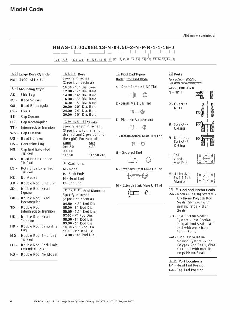
HGAS-10.00x088.13-N-04.50-2-N-P-R-1-1-1E-0
1, 2 3, 4 5, 6, 7, 8 23, 24 25, 2614 19 2720 21 22
All dimensions are in inches.
Large Bore Cylinder
HG – 3000 psi Tie Rod
Mounting Style
AS – Side Lug
JS – Head Square
GS – Head Rectangular
CF – Clevis
SS – Cap Square
PS – Cap Rectangular
TT – Intermediate Trunnion
WS – Cap Trunnion
US – Head Trunnion
HS – Centerline Lug
NS – Cap End Extended Tie Rod
MS – Head End Extended Tie Rod
LS – Both Ends Extended Tie Rod
KS – No Mount
AD – Double Rod, Side Lug
JD – Double Rod, HeadSquare
GD – Double Rod, Head Rectangular
TD – Double Rod, Intermediate Trunnion
UD – Double Rod, HeadTrunnion
HD – Double Rod, Centerline Lug
MD – Double Rod, Extended Tie Rod
LD – Double Rod, Both EndsExtended Tie Rod
KD – Double Rod, No Mount
Bore
Specify in inches (2 position decimal)10.00 - 10” Dia. Bore12.00 - 12” Dia. Bore14.00 - 14” Dia. Bore16.00 - 16” Dia. Bore18.00 - 18” Dia. Bore20.00 - 20” Dia. Bore24.00 - 24” Dia. Bore30.00 - 30” Dia. Bore
Stroke
Specify length in inches (3 positions to the left of decimal and 2 positions to the right). For example:Code Size
004.50 4.50010.00 10112.50 112.50 etc.
Cushions
N - NoneB - Both EndsH - Head EndC - Cap End
Rod Diameter
Specify in inches (2 position decimal)04.50 - 4.5” Rod Dia.05.00 - 5” Rod Dia.05.50 - 5.5” Rod Dia.07.00 - 7” Rod Dia.08.00 - 8” Rod Dia.09.00 - 9” Rod Dia.10.00 - 10” Rod Dia.11.00 - 11” Rod Dia.14.00 - 14” Rod Dia.
Rod End Types
Code - Rod End Style
4 - Short Female UNF Thd
2 - Small Male UN Thd
5 - Plain No Attachment
1 - Intermediate Male UN Thd.
G - Grooved End
K - Extended Small Male UN Thd
M - Extended Int. Male UN Thd
Ports
For maximum reliability, SAE ports are recommended.Code - Port Style
N - NPTF
P - OversizeNPTF
S - SAE/UNF O-Ring
R - Undersize SAE/UNF O-Ring
F - SAE 4-Bolt Manifold
E - Undersize SAE 4-Bolt Manifold
- Rod and Piston Seals
P-R - Normal Sealing System -Urethene Polypak RodSeals, GFT seal withmetalic rings PistonSeals
L-B - Low Friction SealingSystem - Low FrictionPolypak Rod Seals, GFTseal with wear bandPiston Seals
F-V - High TemperatureSealing System - VitonPolypak Rod Seals, VitonGFT seal with metalicrings Piston Seals
Port Locations
1-4 - Head End Position1-4 - Cap End Position
2221
23,24
2019
15, 16, 17, 18
14
9, 10, 11, 12, 13
5, 6, 7, 8
3, 4
1, 2
9, 10, 11, 12, 13 15, 16, 17, 18
5EATON Hydro-Line Large Bore Cylinder Catalog H-CYTR-MC001-E August 2007
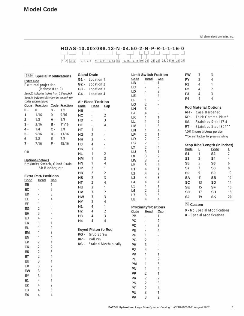
Special Modifications
Extra Rod
Extra rod projection (Inches: 0 to 9)
Item 25 indicates inches from 0 through 9.Item 26 indicates fractions on an inch percodes shown below.Code Fraction Code Fraction
0 - 0 8 - 1/21 - 1/16 9 - 9/162 - 1/8 A - 5/83 - 3/16 B - 11/164 - 1/4 C - 3/45 - 5/16 D - 13/166 - 3/8 E - 7/87 - 7/16 F - 15/16
OR
Options (below)
Proximity Switch, Gland Drain,Air Bleeder, etc.
Extra Port/PositionsCode Head Cap
EB - 1EC - 2ED - 3EE - 4EF 1 -EG 2 -EH 3 -EJ 4 -EK 1 1EL 1 2EM 1 3EN 1 4EP 2 1ER 2 2ES 2 3ET 2 4EU 3 1EV 3 2EW 3 3EY 3 4E1 4 1E2 4 2E3 4 3E4 4 4
Gland Drain
G1 - Location 1G2 - Location 2G3 - Location 3G4 - Location 4
Air Bleed/PositionCode Head Cap
HB - 1HC - 2HD - 3HE - 4HF 1 -HG 2 -HH 3 -HJ 4 -HK 1 1HL 1 2HM 1 3HN 1 4HP 2 1HR 2 2HS 2 3HT 2 4HU 3 1HV 3 2HW 3 3HY 3 4H1 4 1H2 4 2H3 4 3H4 4 4
Keyed Piston to Rod
KG - Grub ScrewKP - Roll PinKS - Staked Mechanically
Limit Switch PositionCode Head Cap
LB - 1LC - 2LD - 3LE - 4LF 1 -LG 2 -LH 3 -LJ 4 -LK 1 1LL 1 2LM 1 3LN 1 4LP 2 1LR 2 2LS 2 3LT 2 4LU 3 1LV 3 2LW 3 3LY 3 4L1 4 1L2 4 2L3 4 3L4 4 4L5 1 1L6 2 2L7 3 3L8 4 4
Proximity/PositionsCode Head Cap
PB - 1PC - 2PD - 3PE - 4PF 1 -PG 2 -PH 3 -PJ 4 -PK 1 1PL 1 2PM 1 3PN 1 4PP 2 1PR 2 2PS 2 3PT 2 4PU 3 1PV 3 2
PW 3 3PY 3 4P1 4 1P2 4 2P3 4 3P4 4 4
Rod Material Options
RH - Case HardenedRP - Thick Chrome Plate*RS - Stainless Steel 17-4RT - Stainless Steel 304***.001 Chrome thickness per side**Consult Factory for pressure rating
Stop Tube/Length (in inches)Code L Code L
S1 1 S2 2S3 3 S4 4S5 5 S6 6S7 7 S8 8S9 9 S0 10SA 11 SB 12SC 13 SD 14SE 15 SF 16SG 17 SH 18SJ 19 SK 20
Custom
0 - No Special ModificationsX - Special Modifications
25,26
27
Model Code
All dimensions are in inches.
HGAS-10.00x088.13-N-04.50-2-N-P-R-1-1-1E-0
1, 2 3, 4 5, 6, 7, 8 23, 24 25, 2614 19 20 21 229, 10, 11, 12, 13 15, 16, 17, 18 27

6 EATON Hydro-Line Large Bore Cylinder Catalog H-CYTR-MC001-E August 2007
How To Order
Standard Cylinders Eaton has created an easysystem for ordering Hydro-Line® HG Series cylinders.This system has been devel-oped to improve our serviceto you. The model code con-sists of alpha-numeric digitswhich fully describe themost common standardoptions offered on HGSeries cylinders.
To specify your HG Seriescylinder, review the follow-ing pages for a full descrip-tion of each option availableand select the desired code.
This model code system will:
• Simplify the re-orderprocess
Each Hydro-Line cylinder isassigned a model code. Thatcode is unique to a particularcylinder description. Thatway, when you re-order yourSeries HG cylinder, you’reassured of exactly the sametop quality cylinder design.
• Improve identification
Every cylinder has its modelcode clearly marked on theproduct. Each code com-pletely describes a specificcylinder. This allows sealsand replacement compo-nents to be easily identifiedin the field.
• Facilitate communica-tions
This fully descriptive modelcode system allows you towork directly with your localEaton sales engineer toidentify and service yourHydro-Line cylinder.
Note: See pages 4 and 5 fora summary of model codeoptions.
Custom Cylinders New Cylinders
Although the model codehas been arranged to coverthe vast majority of availableoptions, there will be occa-sions when you require anoption which cannot becoded. When specifyingsuch an option, enter an “X”for the appropriate item inthe model code, thendescribe your requirements.
For example, if you have anapplication which requires acustom thread on the end ofthe piston rod, enter an “X”for the item. Then add a fulldescription at the end of themodel code, such as “With3.25 inch total rod projectionand M22 x 1.5 thread 1.375inches long.” The cylinderwill then be given a uniquesix digit design number onreceipt of order (asexplained in next section).
Replacement Cylinders
Every custom Hydro-Linecylinder is assigned a uniquedesign number. A customcylinder will have 32 digitsvs. 27 for the standard cylin-der. The design number iscontained in the last six dig-its of the model code, anditem 27 is always an alphacharacter. In other words,the design number beginswhere the 'X' is placed inposition 27 when first speci-fying the custom cylinder.When ordering a replace-ment cylinder, simply givethe model code or the sixdigit design number to yourlocal Hydro-Line cylindersales representative.
Replacement Parts
Each design number isstored in a quick retrievalcomputerized storage sys-tem. This gives our fieldsales representatives rapidaccess to assist you in iden-tifying and specifying gen-uine Hydro-Line replacementparts.
7EATON Hydro-Line Large Bore Cylinder Catalog H-CYTR-MC001-E August 2007
Mounting Style and InstallationDimensions
MountingApplication Guide
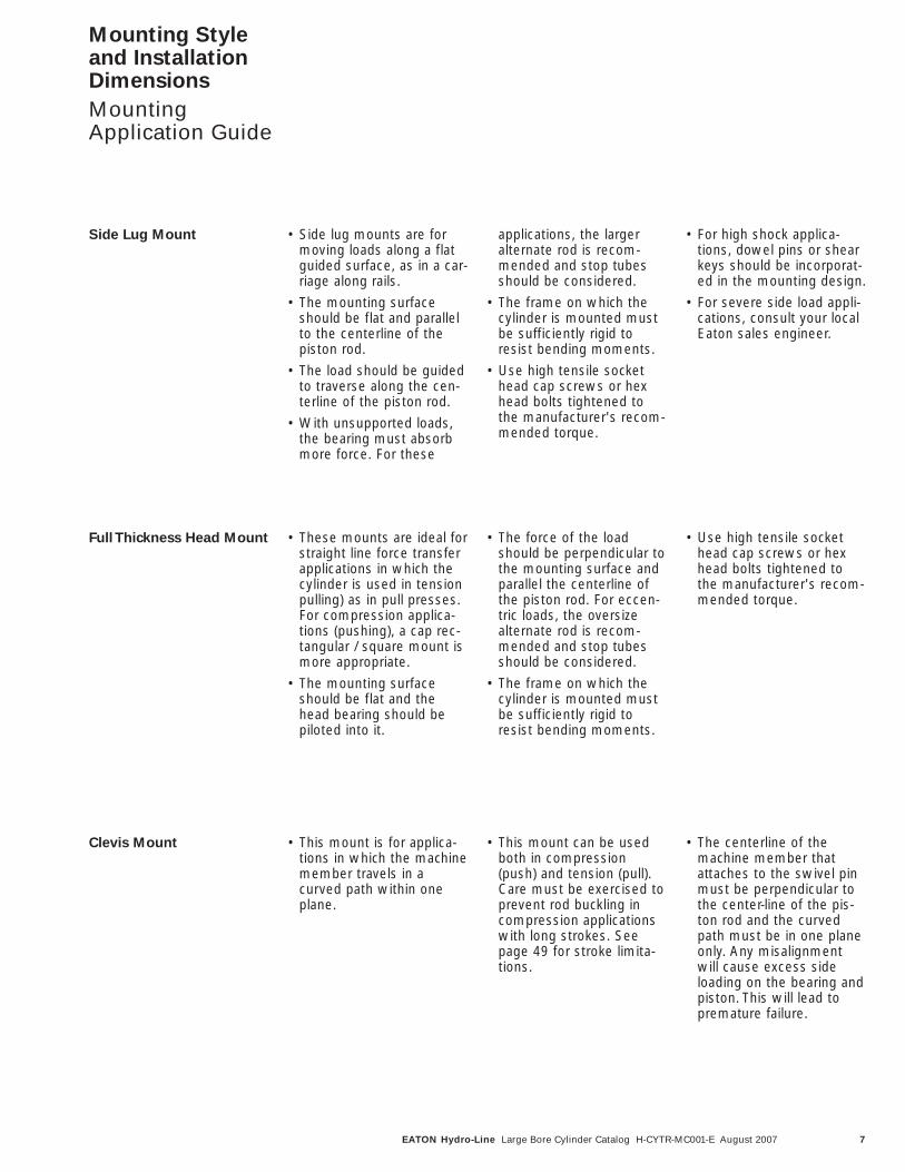
Side Lug Mount • Side lug mounts are formoving loads along a flatguided surface, as in a car-riage along rails.
• The mounting surfaceshould be flat and parallelto the centerline of thepiston rod.
• The load should be guidedto traverse along the cen-terline of the piston rod.
• With unsupported loads,the bearing must absorbmore force. For these
applications, the largeralternate rod is recom-mended and stop tubesshould be considered.
• The frame on which thecylinder is mounted mustbe sufficiently rigid toresist bending moments.
• Use high tensile sockethead cap screws or hexhead bolts tightened tothe manufacturer's recom-mended torque.
• For high shock applica-tions, dowel pins or shearkeys should be incorporat-ed in the mounting design.
• For severe side load appli-cations, consult your localEaton sales engineer.
Full Thickness Head Mount • These mounts are ideal forstraight line force transferapplications in which thecylinder is used in tensionpulling) as in pull presses.For compression applica-tions (pushing), a cap rec-tangular / square mount ismore appropriate.
• The mounting surfaceshould be flat and thehead bearing should bepiloted into it.
• The force of the loadshould be perpendicular tothe mounting surface andparallel the centerline ofthe piston rod. For eccen-tric loads, the oversizealternate rod is recom-mended and stop tubesshould be considered.
• The frame on which thecylinder is mounted mustbe sufficiently rigid toresist bending moments.
• Use high tensile sockethead cap screws or hexhead bolts tightened tothe manufacturer's recom-mended torque.
Clevis Mount • This mount is for applica-tions in which the machinemember travels in acurved path within oneplane.
• This mount can be usedboth in compression(push) and tension (pull).Care must be exercised toprevent rod buckling incompression applicationswith long strokes. Seepage 49 for stroke limita-tions.
• The centerline of themachine member thatattaches to the swivel pinmust be perpendicular tothe center-line of the pis-ton rod and the curvedpath must be in one planeonly. Any misalignmentwill cause excess sideloading on the bearing andpiston. This will lead topremature failure.

8 EATON Hydro-Line Large Bore Cylinder Catalog H-CYTR-MC001-E August 2007
Mounting Style and InstallationDimensions
MountingApplication Guide
Head and Cap TrunnionMounts
• These mounts are forapplications in which themachine member travelsin a curved path withinone plane.
• Either mount can be usedboth in compression(push) and tension (pull)applications. head trunnionmounts provide a longer
maximum stroke than captrunnion mounts, whenused in compression.
• The trunnion pins are anintegral part of the headand can be sleeved to pro-vide an extremely tight fitto the mating machinemember and permit curvi-linear motion.
• It is recommended thatrigidly mounted pillowblocks with bearings atleast as long as the trun-nion pins be used and beinstalled as close to theshoulder of the trunnion aspossible.
Extended Tie Rod Mounts • These mounts are forstraight line force transferapplications. The head endextended tie rod mount isrecommended for tension(pulling) applications andthe cap end extended tierod mount is recommend-ed for compression (push-ing) applications. Bothends extended tie rodmounts are suited for ten-sion and compressionapplications or applicationswhere additional hardwareis to be attached to thecylinders.
• The mounting surfaceshould be flat and theframe on which the cylin-der is mounted must besufficiently rigid to resistbending moments.
• On head mount applica-tions, the bearing providesa pilot diameter to alignthe rod in the mountingframe.
• Once fitted into the appli-cation framework, the nutswhich are provided shouldbe torqued to the valueslisted on page 48. Onsome Both ends extendedtie rod mounts, the nutsmust be loosened on thehead then torqued follow-ing assembly to the frame-work.
• The force on the rodshould be perpendicular tothe mounting surface andcoincide with the center-line of the piston rod. Foreccentric loads, oversizedalternate rods are recom-mended and stop tubesshould be considered.
Double Head Mounts • Double rod end cylindersare specified when equaldisplacement is desired onboth sides of the piston orwhen the application issuch that another functioncan be performed simulta-neously with a second rod.
• The single rod mountapplication data is applica-ble for all double headcylinders.
9EATON Hydro-Line Large Bore Cylinder Catalog H-CYTR-MC001-E August 2007
F
CV
A
ØMM
ØBØRM
SQ E LB + Stroke
ZB + Stroke
GWF
KJ
See RodEnd Pages
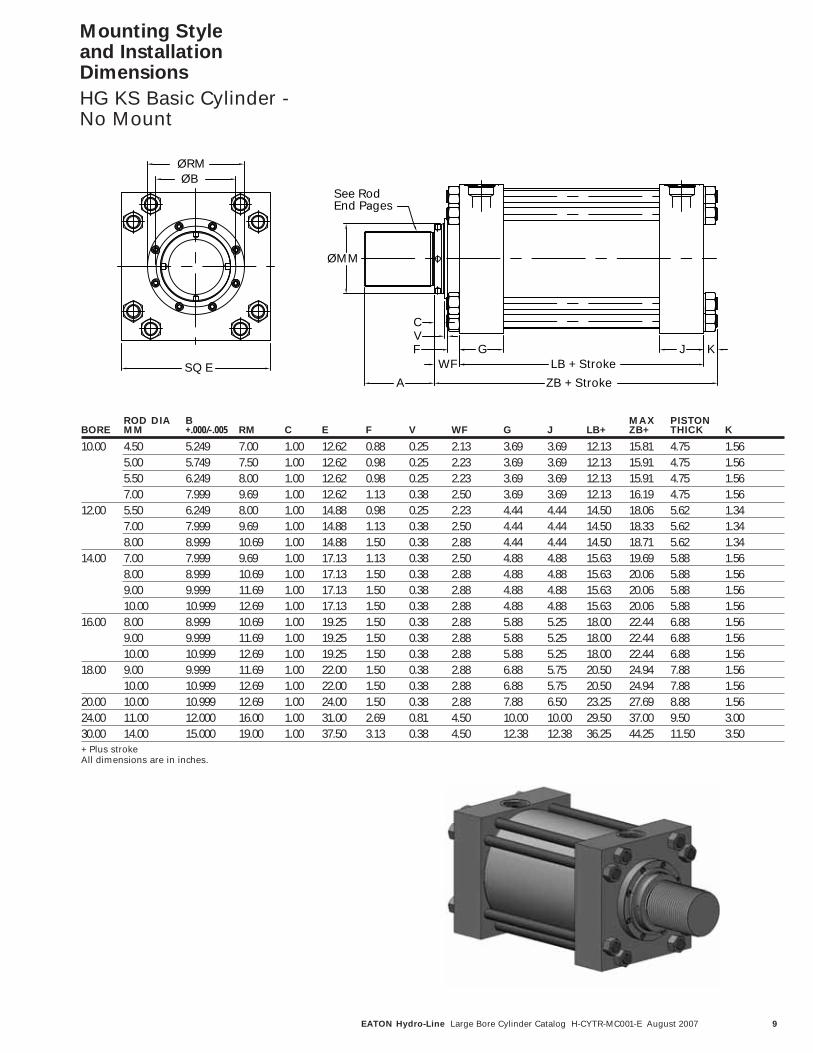
Mounting Style and InstallationDimensions
HG KS Basic Cylinder - No Mount
ROD DIA B MAX PISTONBORE MM +.000/-.005 RM C E F V WF G J LB+ ZB+ THICK K
10.00 4.50 5.249 7.00 1.00 12.62 0.88 0.25 2.13 3.69 3.69 12.13 15.81 4.75 1.565.00 5.749 7.50 1.00 12.62 0.98 0.25 2.23 3.69 3.69 12.13 15.91 4.75 1.565.50 6.249 8.00 1.00 12.62 0.98 0.25 2.23 3.69 3.69 12.13 15.91 4.75 1.567.00 7.999 9.69 1.00 12.62 1.13 0.38 2.50 3.69 3.69 12.13 16.19 4.75 1.56
12.00 5.50 6.249 8.00 1.00 14.88 0.98 0.25 2.23 4.44 4.44 14.50 18.06 5.62 1.347.00 7.999 9.69 1.00 14.88 1.13 0.38 2.50 4.44 4.44 14.50 18.33 5.62 1.348.00 8.999 10.69 1.00 14.88 1.50 0.38 2.88 4.44 4.44 14.50 18.71 5.62 1.34
14.00 7.00 7.999 9.69 1.00 17.13 1.13 0.38 2.50 4.88 4.88 15.63 19.69 5.88 1.568.00 8.999 10.69 1.00 17.13 1.50 0.38 2.88 4.88 4.88 15.63 20.06 5.88 1.569.00 9.999 11.69 1.00 17.13 1.50 0.38 2.88 4.88 4.88 15.63 20.06 5.88 1.5610.00 10.999 12.69 1.00 17.13 1.50 0.38 2.88 4.88 4.88 15.63 20.06 5.88 1.56
16.00 8.00 8.999 10.69 1.00 19.25 1.50 0.38 2.88 5.88 5.25 18.00 22.44 6.88 1.569.00 9.999 11.69 1.00 19.25 1.50 0.38 2.88 5.88 5.25 18.00 22.44 6.88 1.5610.00 10.999 12.69 1.00 19.25 1.50 0.38 2.88 5.88 5.25 18.00 22.44 6.88 1.56
18.00 9.00 9.999 11.69 1.00 22.00 1.50 0.38 2.88 6.88 5.75 20.50 24.94 7.88 1.5610.00 10.999 12.69 1.00 22.00 1.50 0.38 2.88 6.88 5.75 20.50 24.94 7.88 1.56
20.00 10.00 10.999 12.69 1.00 24.00 1.50 0.38 2.88 7.88 6.50 23.25 27.69 8.88 1.5624.00 11.00 12.000 16.00 1.00 31.00 2.69 0.81 4.50 10.00 10.00 29.50 37.00 9.50 3.0030.00 14.00 15.000 19.00 1.00 37.50 3.13 0.38 4.50 12.38 12.38 36.25 44.25 11.50 3.50+ Plus strokeAll dimensions are in inches.
10 EATON Hydro-Line Large Bore Cylinder Catalog H-CYTR-MC001-E August 2007
-.005-.010E/2
SWXS
ZB + StrokeUS
TS3
ST
SWSS + Stroke
SU SU
WF
FVC
ØBØMM
SQ.EØRM
44 X SB †
2
1
LB + StrokeKG J
See RodEnd Pages
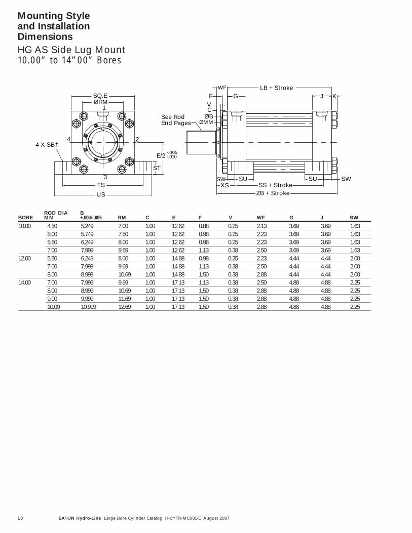
Mounting Style and Installation Dimensions
HG AS Side Lug Mount10.00” to 14”00” Bores
ROD DIA BBORE MM +.000/-.005 RM C E F V WF G J SW
10.00 4.50 5.249 7.00 1.00 12.62 0.88 0.25 2.13 3.69 3.69 1.635.00 5.749 7.50 1.00 12.62 0.98 0.25 2.23 3.69 3.69 1.635.50 6.249 8.00 1.00 12.62 0.98 0.25 2.23 3.69 3.69 1.637.00 7.999 9.69 1.00 12.62 1.13 0.38 2.50 3.69 3.69 1.63
12.00 5.50 6.249 8.00 1.00 14.88 0.98 0.25 2.23 4.44 4.44 2.007.00 7.999 9.69 1.00 14.88 1.13 0.38 2.50 4.44 4.44 2.008.00 8.999 10.69 1.00 14.88 1.50 0.38 2.88 4.44 4.44 2.00
14.00 7.00 7.999 9.69 1.00 17.13 1.13 0.38 2.50 4.88 4.88 2.258.00 8.999 10.69 1.00 17.13 1.50 0.38 2.88 4.88 4.88 2.259.00 9.999 11.69 1.00 17.13 1.50 0.38 2.88 4.88 4.88 2.2510.00 10.999 12.69 1.00 17.13 1.50 0.38 2.88 4.88 4.88 2.25

11EATON Hydro-Line Large Bore Cylinder Catalog H-CYTR-MC001-E August 2007
Mounting Style and Installation Dimensions
HG AS Side Lug Mount10.00” to 14”00” Bores
PISTON MAXBORE XS SS+ SU TS US ST SB† LB+ THICK ZB+ K
10.00 3.75 8.88 3.50 15.88 19.13 2.25 1.56 12.13 4.75 15.81 1.563.85 8.88 3.50 15.88 19.13 2.25 1.56 12.13 4.75 15.91 1.563.85 8.88 3.50 15.88 19.13 2.25 1.56 12.13 4.75 15.91 1.564.13 8.88 3.50 15.88 19.13 2.25 1.56 12.13 4.75 16.19 1.56
12.00 4.23 10.50 4.25 18.88 22.88 3.00 1.56 14.50 5.62 18.06 1.344.50 10.50 4.25 18.88 22.88 3.00 1.56 14.50 5.62 18.33 1.344.88 10.50 4.25 18.88 22.88 3.00 1.56 14.50 5.62 18.71 1.34
14.00 4.75 11.13 4.75 21.63 26.13 4.00 2.31 15.63 5.88 19.69 1.565.13 11.13 4.75 21.63 26.13 4.00 2.31 15.63 5.88 20.06 1.565.13 11.13 4.75 21.63 26.13 4.00 2.31 15.63 5.88 20.06 1.565.13 11.13 4.75 21.63 26.13 4.00 2.31 15.63 5.88 20.06 1.56
+ Plus stroke† Use screws 1/16” smaller than Mounting HolesAll dimensions are in inches.

12 EATON Hydro-Line Large Bore Cylinder Catalog H-CYTR-MC001-E August 2007
ØMM
RE TE
SQ.EX
RESQ.ETE
3 N x ØEB †
ZØRMØB
4
1
2
JLB + Stroke
ZB + Stroke
CV
F GWF K
See RodEnd Pages
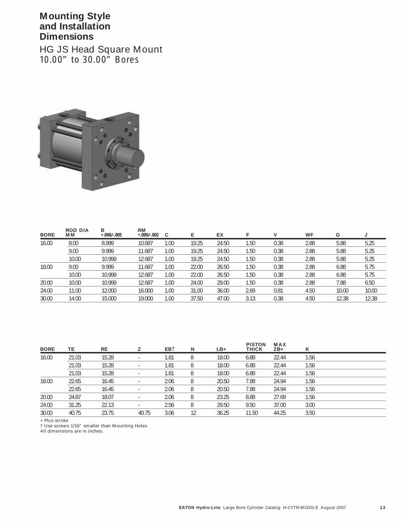
Mounting Style and Installation Dimensions
HG JS Head Square Mount10.00” to 30.00” Bores
ROD DIA B RMBORE MM +.000/-.005 +.000/-.002 C E EX F V WF G J
10.00 4.50 5.249 7.000 1.00 12.62 16.63 0.88 0.25 2.13 3.69 3.695.00 5.749 7.500 1.00 12.62 16.63 0.98 0.25 2.23 3.69 3.695.50 6.249 8.000 1.00 12.62 16.63 0.98 0.25 2.23 3.69 3.697.00 7.999 9.687 1.00 12.62 16.63 1.13 0.38 2.50 3.69 3.69
12.00 5.50 6.249 8.000 1.00 14.88 19.75 0.98 0.25 2.23 4.44 4.447.00 7.999 9.687 1.00 14.88 19.75 1.13 0.38 2.50 4.44 4.448.00 8.999 10.687 1.00 14.88 19.75 1.50 0.38 2.88 4.44 4.44
14.00 7.00 7.999 9.687 1.00 17.13 21.75 1.13 0.38 2.50 4.88 4.888.00 8.999 10.687 1.00 17.13 21.75 1.50 0.38 2.88 4.88 4.889.00 9.999 11.687 1.00 17.13 21.75 1.50 0.38 2.88 4.88 4.8810.00 10.999 12.687 1.00 17.13 21.75 1.50 0.38 2.88 4.88 4.88
PISTON MAXBORE TE RE Z EB† N LB+ THICK ZB+ K
10.00 14.13 9.89 - 1.31 8 12.13 4.75 15.81 1.5614.13 9.89 - 1.31 8 12.13 4.75 15.91 1.5614.13 9.89 - 1.31 8 12.13 4.75 15.91 1.5614.13 9.89 - 1.31 8 12.13 4.75 16.19 1.56
12.00 16.79 11.75 - 1.56 8 14.50 5.62 18.06 1.3416.79 11.75 - 1.56 8 14.50 5.62 18.33 1.3416.79 11.75 - 1.56 8 14.50 5.62 18.71 1.34
14.00 18.43 12.90 - 1.81 8 15.63 5.88 19.69 1.5618.43 12.90 - 1.81 8 15.63 5.88 20.06 1.5618.43 12.90 - 1.81 8 15.63 5.88 20.06 1.5618.43 12.90 - 1.81 8 15.63 5.88 20.06 1.56
+ Plus stroke† Use screws 1/16” smaller than Mounting HolesAll dimensions are in inches.
13EATON Hydro-Line Large Bore Cylinder Catalog H-CYTR-MC001-E August 2007
Mounting Style and Installation Dimensions
HG JS Head Square Mount10.00” to 30.00” Bores
ROD DIA B RMBORE MM +.000/-.005 +.000/-.002 C E EX F V WF G J
16.00 8.00 8.999 10.687 1.00 19.25 24.50 1.50 0.38 2.88 5.88 5.259.00 9.999 11.687 1.00 19.25 24.50 1.50 0.38 2.88 5.88 5.2510.00 10.999 12.687 1.00 19.25 24.50 1.50 0.38 2.88 5.88 5.25
18.00 9.00 9.999 11.687 1.00 22.00 26.50 1.50 0.38 2.88 6.88 5.7510.00 10.999 12.687 1.00 22.00 26.50 1.50 0.38 2.88 6.88 5.75
20.00 10.00 10.999 12.687 1.00 24.00 29.00 1.50 0.38 2.88 7.88 6.5024.00 11.00 12.000 16.000 1.00 31.00 36.00 2.69 0.81 4.50 10.00 10.0030.00 14.00 15.000 19.000 1.00 37.50 47.00 3.13 0.38 4.50 12.38 12.38
PISTON MAXBORE TE RE Z EB† N LB+ THICK ZB+ K
16.00 21.03 15.28 - 1.81 8 18.00 6.88 22.44 1.5621.03 15.28 - 1.81 8 18.00 6.88 22.44 1.5621.03 15.28 - 1.81 8 18.00 6.88 22.44 1.56
18.00 22.65 16.45 - 2.06 8 20.50 7.88 24.94 1.5622.65 16.45 - 2.06 8 20.50 7.88 24.94 1.56
20.00 24.87 18.07 - 2.06 8 23.25 8.88 27.69 1.5624.00 31.25 22.13 - 2.56 8 29.50 9.50 37.00 3.0030.00 40.75 23.75 40.75 3.06 12 36.25 11.50 44.25 3.50+ Plus stroke† Use screws 1/16” smaller than Mounting HolesAll dimensions are in inches.

14 EATON Hydro-Line Large Bore Cylinder Catalog H-CYTR-MC001-E August 2007
ØMMSee Rod End Pages
ØRMØB
UF
TFE
RE
N x ØFB †
X4
3
1
2
ZB + Stroke
LB + StrokeWFG
F
VC
JK
Mounting Style and Installation Dimensions
HG GS Head Rectangular Mount10.00” to 20.00” Bores
ROD DIA B RMBORE MM +.000/-.005 +.000/-.002 C E F V WF G J UF
10.00 4.50 5.249 7.000 1.00 12.62 0.88 0.25 2.13 3.69 3.69 19.005.00 5.749 7.500 1.00 12.62 0.98 0.25 2.23 3.69 3.69 19.005.50 6.249 8.000 1.00 12.62 0.98 0.25 2.23 3.69 3.69 19.007.00 7.999 9.687 1.00 12.62 1.13 0.38 2.50 3.69 3.69 19.00
12.00 5.50 6.249 8.000 1.00 14.88 0.98 0.25 2.23 4.44 4.44 22.007.00 7.999 9.687 1.00 14.88 1.13 0.38 2.50 4.44 4.44 22.008.00 8.999 10.687 1.00 14.88 1.50 0.38 2.88 4.44 4.44 22.00
14.00 7.00 7.999 9.687 1.00 17.13 1.13 0.38 2.50 4.88 4.88 25.008.00 8.999 10.687 1.00 17.13 1.50 0.38 2.88 4.88 4.88 25.009.00 9.999 11.687 1.00 17.13 1.50 0.38 2.88 4.88 4.88 25.0010.00 10.999 12.687 1.00 17.13 1.50 0.38 2.88 4.88 4.88 25.00
PISTON MAXBORE TF R X FB† N LB+ THICK ZB+ K
10.00 15.88 9.63 - 1.81 4 12.13 4.75 15.81 1.5615.88 9.63 - 1.81 4 12.13 4.75 15.91 1.5615.88 9.63 - 1.81 4 12.13 4.75 15.91 1.5615.88 9.63 - 1.81 4 12.13 4.75 16.19 1.56
12.00 18.50 11.45 - 2.06 4 14.50 5.62 18.06 1.3418.50 11.45 - 2.06 4 14.50 5.62 18.33 1.3418.50 11.45 - 2.06 4 14.50 5.62 18.71 1.34
14.00 21.00 13.26 - 2.31 4 15.63 5.88 19.69 1.5621.00 13.26 - 2.31 4 15.63 5.88 20.06 1.5621.00 13.26 - 2.31 4 15.63 5.88 20.06 1.5621.00 13.26 - 2.31 4 15.63 5.88 20.06 1.56
+ Plus stroke† Use screws 1/16” smaller than Mounting HolesAll dimensions are in inches.

15EATON Hydro-Line Large Bore Cylinder Catalog H-CYTR-MC001-E August 2007
Mounting Style and Installation Dimensions
HG GS Head Rectangular Mount10.00” to 20.00” Bores
ROD DIA B RMBORE MM +.000/-.005 +.000/-.002 C E F V WF G J UF
16.00 8.00 8.999 10.687 1.00 19.25 1.50 0.38 2.88 5.88 5.25 25.009.00 9.999 11.687 1.00 19.25 1.50 0.38 2.88 5.88 5.25 25.0010.00 10.999 12.687 1.00 19.25 1.50 0.38 2.88 5.88 5.25 25.00
18.00 9.00 9.999 11.687 1.00 22.00 1.50 0.38 2.88 6.88 5.75 28.2510.00 10.999 12.687 1.00 22.00 1.50 0.38 2.88 6.88 5.75 28.25
20.00 10.00 10.999 12.687 1.00 24.00 1.50 0.38 2.88 7.88 6.50 31.00
PISTON MAXBORE TF R X FB† N LB+ THICK ZB+ K
16.00 21.00 15.50 8.00 1.81 8 18.00 6.88 22.44 1.5621.00 15.50 8.00 1.81 8 18.00 6.88 22.44 1.5621.00 15.50 8.00 1.81 8 18.00 6.88 22.44 1.56
18.00 24.25 18.00 7.25 2.06 8 20.50 7.88 24.94 1.5624.25 18.00 7.25 2.06 8 20.50 7.88 24.94 1.56
20.00 26.50 20.00 8.00 2.06 8 23.25 8.88 27.69 1.56+ Plus stroke† Use screws 1/16” smaller than Mounting HolesAll dimensions are in inches.

16 EATON Hydro-Line Large Bore Cylinder Catalog H-CYTR-MC001-E August 2007
Mounting Style and Installation Dimensions
HG CF Clevis Mount10.00” to 30.00” Bores
XC + Stroke
L
LR
LB + StrokeG
CV
WFF
K
ØB
ØMM
J
SQ.E CW
ØRM
M CW CB†3
CDM
2
1
4
See RodEnd Pages
ROD DIA BBORE MM +.000/-.005 RM C E F V WF G J L
10.00 4.50 5.249 7.00 1.00 12.62 0.88 0.25 2.13 3.69 3.69 4.005.00 5.749 7.50 1.00 12.62 0.98 0.25 2.23 3.69 3.69 4.005.50 6.249 8.00 1.00 12.62 0.98 0.25 2.23 3.69 3.69 4.007.00 7.999 9.69 1.00 12.62 1.13 0.38 2.50 3.69 3.69 4.00
12.00 5.50 6.249 8.00 1.00 14.88 0.98 0.25 2.23 4.44 4.44 4.507.00 7.999 9.69 1.00 14.88 1.13 0.38 2.50 4.44 4.44 4.508.00 8.999 10.69 1.00 14.88 1.50 0.38 2.88 4.44 4.44 4.50
14.00 7.00 7.999 9.69 1.00 17.13 1.13 0.38 2.50 4.88 4.88 5.758.00 8.999 10.69 1.00 17.13 1.50 0.38 2.88 4.88 4.88 5.759.00 9.999 11.69 1.00 17.13 1.50 0.38 2.88 4.88 4.88 5.7510.00 10.999 12.69 1.00 17.13 1.50 0.38 2.88 4.88 4.88 5.75
PISTONBORE M LR CD CW CB† LB+ XC+ THICK K
10.00 3.50 3.63 3.50 2.00 4.00 12.13 18.25 4.75 1.563.50 3.63 3.50 2.00 4.00 12.13 18.35 4.75 1.563.50 3.63 3.50 2.00 4.00 12.13 18.35 4.75 1.563.50 3.63 3.50 2.00 4.00 12.13 18.63 4.75 1.56
12.00 4.00 4.13 4.00 2.25 4.50 14.50 21.22 5.62 1.344.00 4.13 4.00 2.25 4.50 14.50 21.50 5.62 1.344.00 4.13 4.00 2.25 4.50 14.50 21.87 5.62 1.34
14.00 5.00 5.13 5.00 3.00 6.00 15.63 23.88 5.88 1.565.00 5.13 5.00 3.00 6.00 15.63 24.25 5.88 1.565.00 5.13 5.00 3.00 6.00 15.63 24.25 5.88 1.565.00 5.13 5.00 3.00 6.00 15.63 24.25 5.88 1.56
+ Plus stroke† Maximum width of mating partAll dimensions are in inches.

17EATON Hydro-Line Large Bore Cylinder Catalog H-CYTR-MC001-E August 2007
Mounting Style and Installation Dimensions
HG CF Clevis Mount10.00” to 30.00” Bores
ROD DIA BBORE MM +.000/-.005 RM C E F V WF G J L
16.00 8.00 8.999 10.69 1.00 19.25 1.50 0.38 2.88 5.88 5.25 7.009.00 9.999 11.69 1.00 19.25 1.50 0.38 2.88 5.88 5.25 7.0010.00 10.999 12.69 1.00 19.25 1.50 0.38 2.88 5.88 5.25 7.00
18.00 9.00 9.999 11.69 1.00 22.00 1.50 0.38 2.88 6.88 5.75 7.6310.00 10.999 12.69 1.00 22.00 1.50 0.38 2.88 6.88 5.75 7.63
20.00 10.00 10.999 12.69 1.00 24.00 1.50 0.38 2.88 7.88 6.50 8.7524.00 11.00 12.000 16.00 1.00 31.00 2.69 0.81 4.50 10.00 10.00 17.0030.00 14.00 15.000 19.00 1.00 37.50 3.13 0.38 4.50 12.38 12.38 21.00
PISTONBORE M LR CD CW CB† LB+ XC+ THICK K
16.00 6.00 6.25 6.00 3.50 7.00 18.00 27.88 6.88 1.566.00 6.25 6.00 3.50 7.00 18.00 27.88 6.88 1.566.00 6.25 6.00 3.50 7.00 18.00 27.88 6.88 1.56
18.00 6.50 6.75 6.50 4.00 8.00 20.50 31.00 7.88 1.566.50 6.75 6.50 4.00 8.00 20.50 31.00 7.88 1.56
20.00 7.50 6.19 7.50 4.50 9.00 23.25 34.88 8.88 1.5624.00 9.00 - 9.00 5.00 11.00 29.50 51.00 9.50 3.0030.00 11.00 - 11.00 6.00 12.00 36.25 61.75 11.50 3.50+ Plus stroke† Maximum width of mating partAll dimensions are in inches.
18 EATON Hydro-Line Large Bore Cylinder Catalog H-CYTR-MC001-E August 2007
VFC
ØMM
ØRM
TE
ØB
SQ.EXTE
RE
4
3 N x ØEB†
RE2
SQ.EZ
1
ZJ + Stroke
LB + Stroke
J
WF
G
K
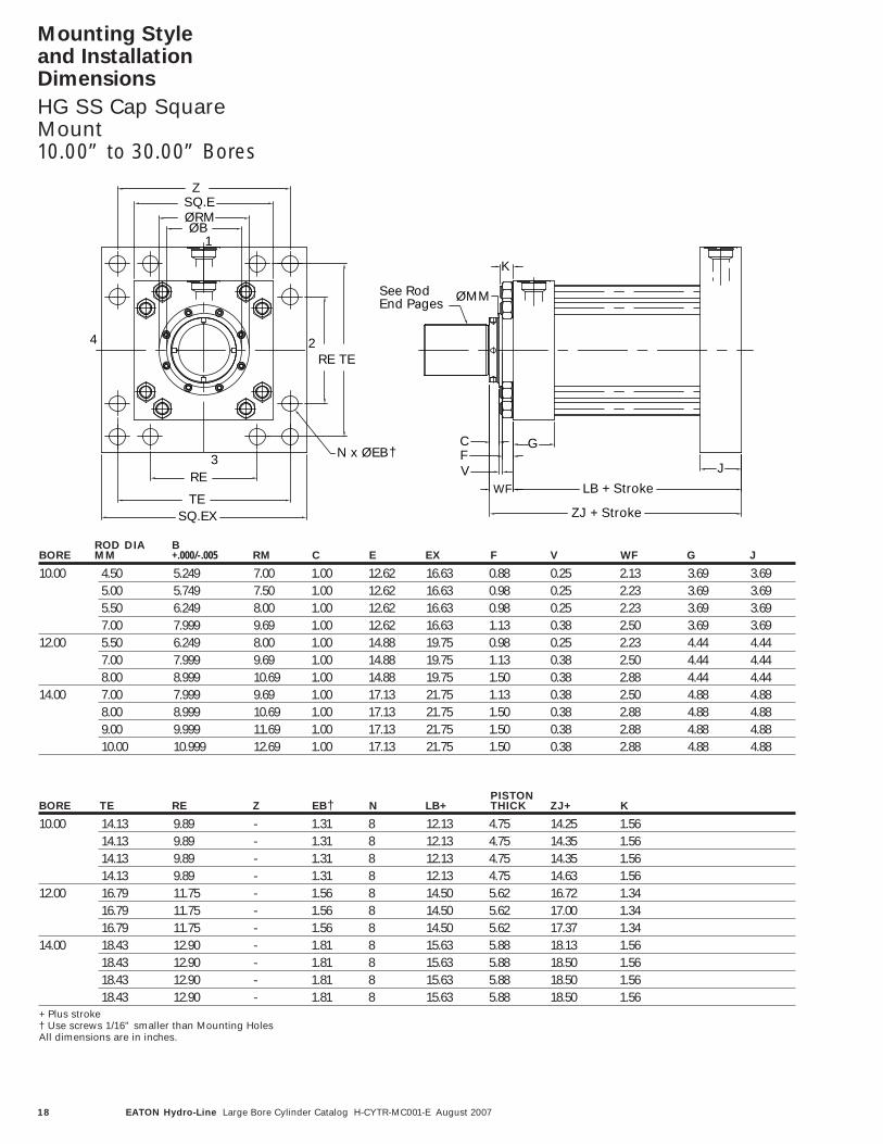
See RodEnd Pages
ROD DIA BBORE MM +.000/-.005 RM C E EX F V WF G J
10.00 4.50 5.249 7.00 1.00 12.62 16.63 0.88 0.25 2.13 3.69 3.695.00 5.749 7.50 1.00 12.62 16.63 0.98 0.25 2.23 3.69 3.695.50 6.249 8.00 1.00 12.62 16.63 0.98 0.25 2.23 3.69 3.697.00 7.999 9.69 1.00 12.62 16.63 1.13 0.38 2.50 3.69 3.69
12.00 5.50 6.249 8.00 1.00 14.88 19.75 0.98 0.25 2.23 4.44 4.447.00 7.999 9.69 1.00 14.88 19.75 1.13 0.38 2.50 4.44 4.448.00 8.999 10.69 1.00 14.88 19.75 1.50 0.38 2.88 4.44 4.44
14.00 7.00 7.999 9.69 1.00 17.13 21.75 1.13 0.38 2.50 4.88 4.888.00 8.999 10.69 1.00 17.13 21.75 1.50 0.38 2.88 4.88 4.889.00 9.999 11.69 1.00 17.13 21.75 1.50 0.38 2.88 4.88 4.8810.00 10.999 12.69 1.00 17.13 21.75 1.50 0.38 2.88 4.88 4.88
PISTONBORE TE RE Z EB† N LB+ THICK ZJ+ K
10.00 14.13 9.89 - 1.31 8 12.13 4.75 14.25 1.5614.13 9.89 - 1.31 8 12.13 4.75 14.35 1.5614.13 9.89 - 1.31 8 12.13 4.75 14.35 1.5614.13 9.89 - 1.31 8 12.13 4.75 14.63 1.56
12.00 16.79 11.75 - 1.56 8 14.50 5.62 16.72 1.3416.79 11.75 - 1.56 8 14.50 5.62 17.00 1.3416.79 11.75 - 1.56 8 14.50 5.62 17.37 1.34
14.00 18.43 12.90 - 1.81 8 15.63 5.88 18.13 1.5618.43 12.90 - 1.81 8 15.63 5.88 18.50 1.5618.43 12.90 - 1.81 8 15.63 5.88 18.50 1.5618.43 12.90 - 1.81 8 15.63 5.88 18.50 1.56
+ Plus stroke† Use screws 1/16” smaller than Mounting HolesAll dimensions are in inches.
Mounting Style and Installation Dimensions
HG SS Cap SquareMount10.00” to 30.00” Bores

19EATON Hydro-Line Large Bore Cylinder Catalog H-CYTR-MC001-E August 2007
Mounting Style and Installation Dimensions
HG SS Cap SquareMount10.00” to 30.00” Bores
PISTONBORE TE RE Z EB† N LB+ THICK ZJ+ K
16.00 21.03 15.28 - 1.81 8 18.00 6.88 20.88 1.5621.03 15.28 - 1.81 8 18.00 6.88 20.88 1.5621.03 15.28 - 1.81 8 18.00 6.88 20.88 1.56
18.00 22.65 16.45 - 2.06 8 20.50 7.88 23.38 1.5622.65 16.45 - 2.06 8 20.50 7.88 23.38 1.56
20.00 24.87 18.07 - 2.06 8 23.25 8.88 26.13 1.5624.00 31.25 22.13 - 2.56 8 29.50 9.50 34.00 3.0030.00 40.75 23.75 40.75 3.06 12 36.25 11.50 40.75 3.50+ Plus stroke† Use screws 1/16” smaller than Mounting HolesAll dimensions are in inches.
ROD DIA BBORE MM +.000/-.005 RM C E EX F V WF G J
16.00 8.00 8.999 10.69 1.00 19.25 24.50 1.50 0.38 2.88 5.88 5.259.00 9.999 11.69 1.00 19.25 24.50 1.50 0.38 2.88 5.88 5.2510.00 10.999 12.69 1.00 19.25 24.50 1.50 0.38 2.88 5.88 5.25
18.00 9.00 9.999 11.69 1.00 22.00 26.50 1.50 0.38 2.88 6.88 5.7510.00 10.999 12.69 1.00 22.00 26.50 1.50 0.38 2.88 6.88 5.75
20.00 10.00 10.999 12.69 1.00 24.00 29.00 1.50 0.38 2.88 7.88 6.5024.00 11.00 12.000 16.00 1.00 31.00 36.00 2.69 0.81 4.50 10.00 10.0030.00 14.00 15.000 19.00 1.00 37.50 47.00 3.13 0.38 4.50 12.38 12.38

20 EATON Hydro-Line Large Bore Cylinder Catalog H-CYTR-MC001-E August 2007
Mounting Style and Installation Dimensions
HG PS Cap RectangularMount10.00” to 20.00” Bores
ØMM
ØRMØB
UF
TFE
RE
N x ØFB †
X4
3
1
2
ZJ + StrokeLB + StrokeWF
G
F
VC
K
J
See RodEnd Pages
PISTONBORE TF R X FB† N LB+ THICK ZJ+ K
10.00 15.88 9.63 - 1.81 4 12.13 4.75 14.25 1.5615.88 9.63 - 1.81 4 12.13 4.75 14.35 1.5615.88 9.63 - 1.81 4 12.13 4.75 14.35 1.5615.88 9.63 - 1.81 4 12.13 4.75 14.63 1.56
12.00 18.50 11.45 - 2.06 4 14.50 5.62 16.72 1.3418.50 11.45 - 2.06 4 14.50 5.62 17.00 1.3418.50 11.45 - 2.06 4 14.50 5.62 17.38 1.34
14.00 21.00 13.26 - 2.31 4 15.63 5.88 18.13 1.5621.00 13.26 - 2.31 4 15.63 5.88 18.50 1.5621.00 13.26 - 2.31 4 15.63 5.88 18.50 1.5621.00 13.26 - 2.31 4 15.63 5.88 18.50 1.56
+ Plus stroke† Use screws 1/16” smaller than Mounting HolesAll dimensions are in inches.
ROD DIA BBORE MM +.000/-.005 RM C E F V WF G J UF
10.00 4.50 5.249 7.00 1.00 12.62 0.88 0.25 2.13 3.69 3.69 19.005.00 5.749 7.50 1.00 12.62 0.98 0.25 2.23 3.69 3.69 19.005.50 6.249 8.00 1.00 12.62 0.98 0.25 2.23 3.69 3.69 19.007.00 7.999 9.69 1.00 12.62 1.13 0.38 2.50 3.69 3.69 19.00
12.00 5.50 6.249 8.00 1.00 14.88 0.98 0.25 2.23 4.44 4.44 22.007.00 7.999 9.69 1.00 14.88 1.13 0.38 2.50 4.44 4.44 22.008.00 8.999 10.69 1.00 14.88 1.50 0.38 2.88 4.44 4.44 22.00
14.00 7.00 7.999 9.69 1.00 17.13 1.13 0.38 2.50 4.88 4.88 25.008.00 8.999 10.69 1.00 17.13 1.50 0.38 2.88 4.88 4.88 25.009.00 9.999 11.69 1.00 17.13 1.50 0.38 2.88 4.88 4.88 25.0010.00 10.999 12.69 1.00 17.13 1.50 0.38 2.88 4.88 4.88 25.00

21EATON Hydro-Line Large Bore Cylinder Catalog H-CYTR-MC001-E August 2007
Mounting Style and Installation Dimensions
HG PS Cap RectangularMount10.00” to 20.00” Bores
ROD DIA BBORE MM +.000/-.005 RM C E F V WF G J UF
16.00 8.00 8.999 10.69 1.00 19.25 1.50 0.38 2.88 5.88 5.25 25.009.00 9.999 11.69 1.00 19.25 1.50 0.38 2.88 5.88 5.25 25.0010.00 10.999 12.69 1.00 19.25 1.50 0.38 2.88 5.88 5.25 25.00
18.00 9.00 9.999 11.69 1.00 22.00 1.50 0.38 2.88 6.88 5.75 28.2510.00 10.999 12.69 1.00 22.00 1.50 0.38 2.88 6.88 5.75 28.25
20.00 10.00 10.999 12.69 1.00 24.00 1.50 0.38 2.88 7.88 6.50 31.00
PISTONBORE TF R X FB† N LB+ THICK ZJ+ K
16.00 21.00 15.50 8.00 1.81 8 18.00 6.88 20.88 1.5621.00 15.50 8.00 1.81 8 18.00 6.88 20.88 1.5621.00 15.50 8.00 1.81 8 18.00 6.88 20.88 1.56
18.00 21.00 18.00 7.25 2.06 8 20.50 7.88 23.38 1.5621.00 18.00 7.25 2.06 8 20.50 7.88 23.38 1.56
20.00 26.50 20.00 8.00 2.06 8 23.25 8.88 26.13 1.56+ Plus stroke† Use screws 1/16” smaller than Mounting HolesAll dimensions are in inches.
22 EATON Hydro-Line Large Bore Cylinder Catalog H-CYTR-MC001-E August 2007
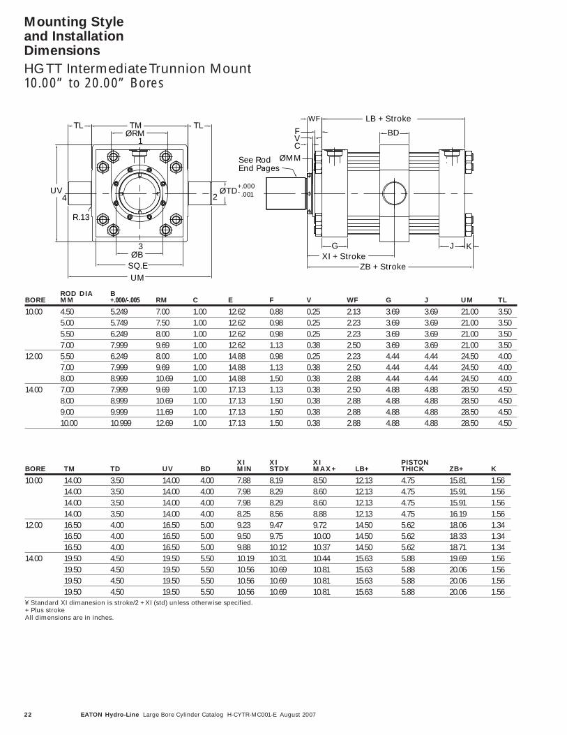
Mounting Style and Installation Dimensions
HG TT Intermediate Trunnion Mount10.00” to 20.00” Bores
CVF
ØMM
SQ.E
ØRM
UM
TM
ØB
UV
3
TL
4
R.13
1
ØTD
TL
2+.000- .001
ZB + Stroke
LB + Stroke
JXI + Stroke
G
WF
BD
K
See RodEnd Pages
ROD DIA BBORE MM +.000/-.005 RM C E F V WF G J UM TL
10.00 4.50 5.249 7.00 1.00 12.62 0.88 0.25 2.13 3.69 3.69 21.00 3.505.00 5.749 7.50 1.00 12.62 0.98 0.25 2.23 3.69 3.69 21.00 3.505.50 6.249 8.00 1.00 12.62 0.98 0.25 2.23 3.69 3.69 21.00 3.507.00 7.999 9.69 1.00 12.62 1.13 0.38 2.50 3.69 3.69 21.00 3.50
12.00 5.50 6.249 8.00 1.00 14.88 0.98 0.25 2.23 4.44 4.44 24.50 4.007.00 7.999 9.69 1.00 14.88 1.13 0.38 2.50 4.44 4.44 24.50 4.008.00 8.999 10.69 1.00 14.88 1.50 0.38 2.88 4.44 4.44 24.50 4.00
14.00 7.00 7.999 9.69 1.00 17.13 1.13 0.38 2.50 4.88 4.88 28.50 4.508.00 8.999 10.69 1.00 17.13 1.50 0.38 2.88 4.88 4.88 28.50 4.509.00 9.999 11.69 1.00 17.13 1.50 0.38 2.88 4.88 4.88 28.50 4.5010.00 10.999 12.69 1.00 17.13 1.50 0.38 2.88 4.88 4.88 28.50 4.50
XI XI XI PISTONBORE TM TD UV BD MIN STD¥ MAX+ LB+ THICK ZB+ K
10.00 14.00 3.50 14.00 4.00 7.88 8.19 8.50 12.13 4.75 15.81 1.5614.00 3.50 14.00 4.00 7.98 8.29 8.60 12.13 4.75 15.91 1.5614.00 3.50 14.00 4.00 7.98 8.29 8.60 12.13 4.75 15.91 1.5614.00 3.50 14.00 4.00 8.25 8.56 8.88 12.13 4.75 16.19 1.56
12.00 16.50 4.00 16.50 5.00 9.23 9.47 9.72 14.50 5.62 18.06 1.3416.50 4.00 16.50 5.00 9.50 9.75 10.00 14.50 5.62 18.33 1.3416.50 4.00 16.50 5.00 9.88 10.12 10.37 14.50 5.62 18.71 1.34
14.00 19.50 4.50 19.50 5.50 10.19 10.31 10.44 15.63 5.88 19.69 1.5619.50 4.50 19.50 5.50 10.56 10.69 10.81 15.63 5.88 20.06 1.5619.50 4.50 19.50 5.50 10.56 10.69 10.81 15.63 5.88 20.06 1.5619.50 4.50 19.50 5.50 10.56 10.69 10.81 15.63 5.88 20.06 1.56
¥ Standard XI dimanesion is stroke/2 + XI (std) unless otherwise specified.+ Plus strokeAll dimensions are in inches.

23EATON Hydro-Line Large Bore Cylinder Catalog H-CYTR-MC001-E August 2007
Mounting Style and Installation Dimensions
HG TT Intermediate Trunnion Mount10.00” to 20.00” Bores
ROD DIA BBORE MM +.000/-.005 RM C E F V WF G J UM TL
16.00 8.00 8.999 10.69 1.00 19.25 1.50 0.38 2.88 5.88 5.25 45.25 8.009.00 9.999 11.69 1.00 19.25 1.50 0.38 2.88 5.88 5.25 45.25 8.0010.00 10.999 12.69 1.00 19.25 1.50 0.38 2.88 5.88 5.25 45.25 8.00
18.00 9.00 9.999 11.69 1.00 22.00 1.50 0.38 2.88 6.88 5.75 51.25 9.0010.00 10.999 12.69 1.00 22.00 1.50 0.38 2.88 6.88 5.75 51.25 9.00
20.00 10.00 10.999 12.69 1.00 24.00 1.50 0.38 2.88 7.88 6.50 57.50 10.00
MAXIMUMWORKING
BORE PRESSURE (PSI)
10.00 160012.00 150014.00 140016.00 300018.00 300020.00 3000
XI XI XI PISTONBORE TM TD UV BD MIN STD¥ MAX+ LB+ THICK ZB+ K
16.00 29.25 8.00 26.50 8.75 13.19 11.88 11.19 18.00 6.88 22.44 1.5629.25 8.00 26.50 8.75 13.19 11.88 11.19 18.00 6.88 22.44 1.5629.25 8.00 26.50 8.75 13.19 11.88 11.19 18.00 6.88 22.44 1.56
18.00 33.25 9.00 30.00 9.75 14.69 13.13 12.69 20.50 7.88 24.94 1.5633.25 9.00 30.00 9.75 14.69 13.13 12.69 20.50 7.88 24.94 1.56
20.00 37.50 10.00 33.50 10.75 16.19 14.50 14.19 23.25 8.88 27.69 1.56¥ Standard XI dimanesion is stroke/2 + XI (std) unless otherwise specified.+ Plus strokeAll dimensions are in inches.
24 EATON Hydro-Line Large Bore Cylinder Catalog H-CYTR-MC001-E August 2007
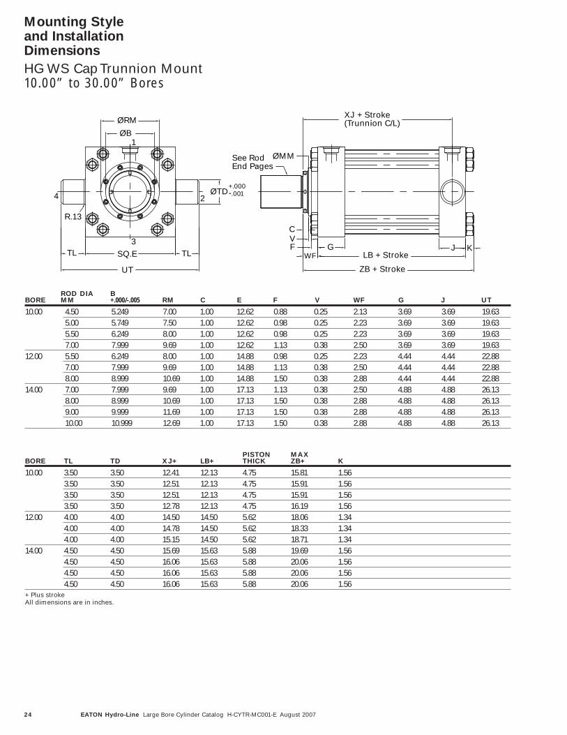
Mounting Style and Installation Dimensions
HG WS Cap Trunnion Mount10.00” to 30.00” Bores
ØMM
ØB
UT
ØRM
SQ.E
R.13
TL
4
TL3
1
+.000- .001ØTD
2
LB + Stroke
ZB + Stroke
XJ + Stroke(Trunnion C/L)
JGWF
F
CV
K
See RodEnd Pages
ROD DIA BBORE MM +.000/-.005 RM C E F V WF G J UT
10.00 4.50 5.249 7.00 1.00 12.62 0.88 0.25 2.13 3.69 3.69 19.635.00 5.749 7.50 1.00 12.62 0.98 0.25 2.23 3.69 3.69 19.635.50 6.249 8.00 1.00 12.62 0.98 0.25 2.23 3.69 3.69 19.637.00 7.999 9.69 1.00 12.62 1.13 0.38 2.50 3.69 3.69 19.63
12.00 5.50 6.249 8.00 1.00 14.88 0.98 0.25 2.23 4.44 4.44 22.887.00 7.999 9.69 1.00 14.88 1.13 0.38 2.50 4.44 4.44 22.888.00 8.999 10.69 1.00 14.88 1.50 0.38 2.88 4.44 4.44 22.88
14.00 7.00 7.999 9.69 1.00 17.13 1.13 0.38 2.50 4.88 4.88 26.138.00 8.999 10.69 1.00 17.13 1.50 0.38 2.88 4.88 4.88 26.139.00 9.999 11.69 1.00 17.13 1.50 0.38 2.88 4.88 4.88 26.1310.00 10.999 12.69 1.00 17.13 1.50 0.38 2.88 4.88 4.88 26.13
PISTON MAXBORE TL TD XJ+ LB+ THICK ZB+ K
10.00 3.50 3.50 12.41 12.13 4.75 15.81 1.563.50 3.50 12.51 12.13 4.75 15.91 1.563.50 3.50 12.51 12.13 4.75 15.91 1.563.50 3.50 12.78 12.13 4.75 16.19 1.56
12.00 4.00 4.00 14.50 14.50 5.62 18.06 1.344.00 4.00 14.78 14.50 5.62 18.33 1.344.00 4.00 15.15 14.50 5.62 18.71 1.34
14.00 4.50 4.50 15.69 15.63 5.88 19.69 1.564.50 4.50 16.06 15.63 5.88 20.06 1.564.50 4.50 16.06 15.63 5.88 20.06 1.564.50 4.50 16.06 15.63 5.88 20.06 1.56
+ Plus strokeAll dimensions are in inches.
25EATON Hydro-Line Large Bore Cylinder Catalog H-CYTR-MC001-E August 2007
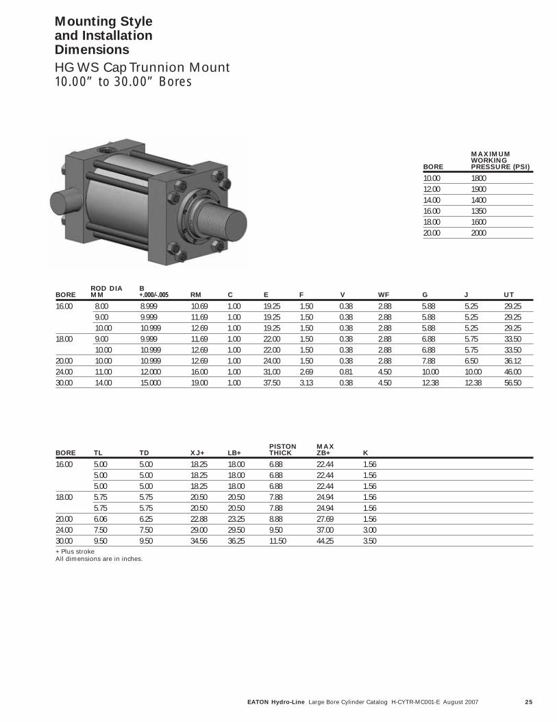
Mounting Style and Installation Dimensions
HG WS Cap Trunnion Mount10.00” to 30.00” Bores
ROD DIA BBORE MM +.000/-.005 RM C E F V WF G J UT
16.00 8.00 8.999 10.69 1.00 19.25 1.50 0.38 2.88 5.88 5.25 29.259.00 9.999 11.69 1.00 19.25 1.50 0.38 2.88 5.88 5.25 29.2510.00 10.999 12.69 1.00 19.25 1.50 0.38 2.88 5.88 5.25 29.25
18.00 9.00 9.999 11.69 1.00 22.00 1.50 0.38 2.88 6.88 5.75 33.5010.00 10.999 12.69 1.00 22.00 1.50 0.38 2.88 6.88 5.75 33.50
20.00 10.00 10.999 12.69 1.00 24.00 1.50 0.38 2.88 7.88 6.50 36.1224.00 11.00 12.000 16.00 1.00 31.00 2.69 0.81 4.50 10.00 10.00 46.0030.00 14.00 15.000 19.00 1.00 37.50 3.13 0.38 4.50 12.38 12.38 56.50
PISTON MAXBORE TL TD XJ+ LB+ THICK ZB+ K
16.00 5.00 5.00 18.25 18.00 6.88 22.44 1.565.00 5.00 18.25 18.00 6.88 22.44 1.565.00 5.00 18.25 18.00 6.88 22.44 1.56
18.00 5.75 5.75 20.50 20.50 7.88 24.94 1.565.75 5.75 20.50 20.50 7.88 24.94 1.56
20.00 6.06 6.25 22.88 23.25 8.88 27.69 1.5624.00 7.50 7.50 29.00 29.50 9.50 37.00 3.0030.00 9.50 9.50 34.56 36.25 11.50 44.25 3.50+ Plus strokeAll dimensions are in inches.
MAXIMUMWORKING
BORE PRESSURE (PSI)
10.00 180012.00 190014.00 140016.00 135018.00 160020.00 2000
26 EATON Hydro-Line Large Bore Cylinder Catalog H-CYTR-MC001-E August 2007
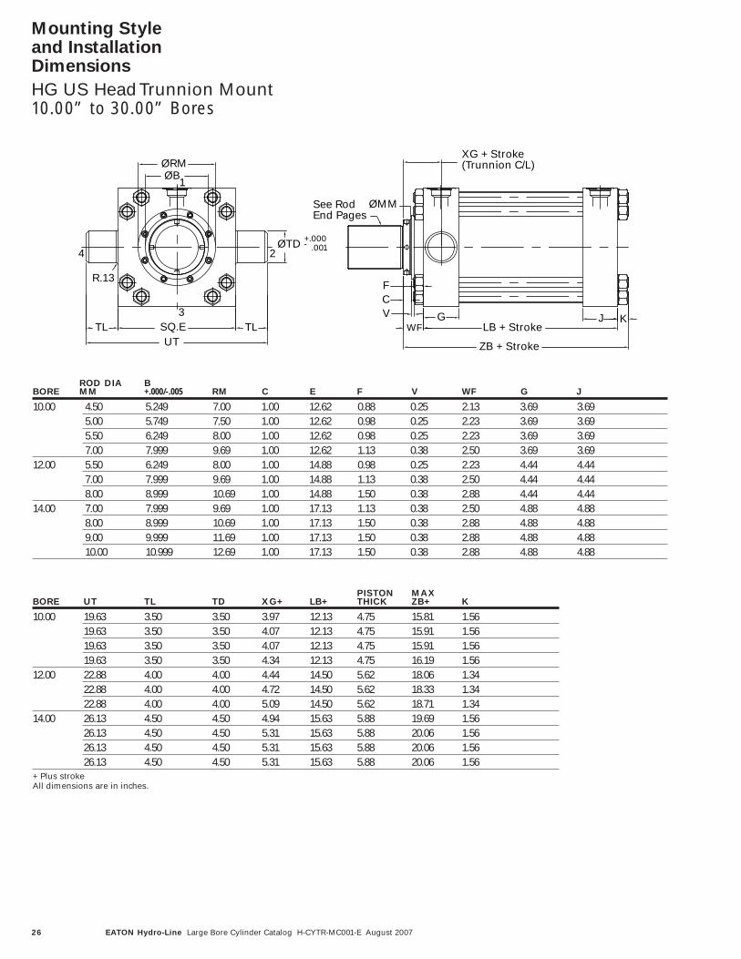
Mounting Style and Installation Dimensions
HG US Head Trunnion Mount10.00” to 30.00” Bores
ØMM
UTSQ.E
ØRMØB
TL
R.13
4
3TL
ØTD
1
2+.000- .001
ZB + Stroke
LB + StrokeJV
C
WF
F
G
XG + Stroke(Trunnion C/L)
K
See RodEnd Pages
ROD DIA BBORE MM +.000/-.005 RM C E F V WF G J
10.00 4.50 5.249 7.00 1.00 12.62 0.88 0.25 2.13 3.69 3.695.00 5.749 7.50 1.00 12.62 0.98 0.25 2.23 3.69 3.695.50 6.249 8.00 1.00 12.62 0.98 0.25 2.23 3.69 3.697.00 7.999 9.69 1.00 12.62 1.13 0.38 2.50 3.69 3.69
12.00 5.50 6.249 8.00 1.00 14.88 0.98 0.25 2.23 4.44 4.447.00 7.999 9.69 1.00 14.88 1.13 0.38 2.50 4.44 4.448.00 8.999 10.69 1.00 14.88 1.50 0.38 2.88 4.44 4.44
14.00 7.00 7.999 9.69 1.00 17.13 1.13 0.38 2.50 4.88 4.888.00 8.999 10.69 1.00 17.13 1.50 0.38 2.88 4.88 4.889.00 9.999 11.69 1.00 17.13 1.50 0.38 2.88 4.88 4.8810.00 10.999 12.69 1.00 17.13 1.50 0.38 2.88 4.88 4.88
PISTON MAXBORE UT TL TD XG+ LB+ THICK ZB+ K
10.00 19.63 3.50 3.50 3.97 12.13 4.75 15.81 1.5619.63 3.50 3.50 4.07 12.13 4.75 15.91 1.5619.63 3.50 3.50 4.07 12.13 4.75 15.91 1.5619.63 3.50 3.50 4.34 12.13 4.75 16.19 1.56
12.00 22.88 4.00 4.00 4.44 14.50 5.62 18.06 1.3422.88 4.00 4.00 4.72 14.50 5.62 18.33 1.3422.88 4.00 4.00 5.09 14.50 5.62 18.71 1.34
14.00 26.13 4.50 4.50 4.94 15.63 5.88 19.69 1.5626.13 4.50 4.50 5.31 15.63 5.88 20.06 1.5626.13 4.50 4.50 5.31 15.63 5.88 20.06 1.5626.13 4.50 4.50 5.31 15.63 5.88 20.06 1.56
+ Plus strokeAll dimensions are in inches.
27EATON Hydro-Line Large Bore Cylinder Catalog H-CYTR-MC001-E August 2007
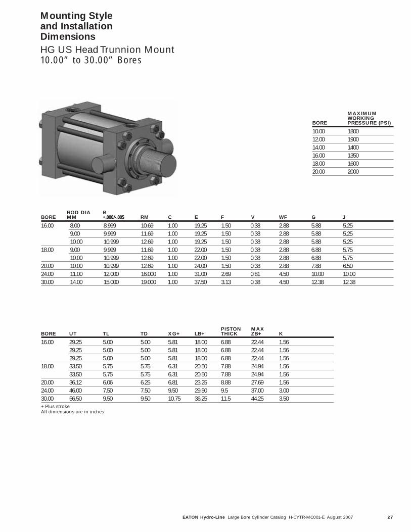
Mounting Style and Installation Dimensions
HG US Head Trunnion Mount10.00” to 30.00” Bores
ROD DIA BBORE MM +.000/-.005 RM C E F V WF G J
16.00 8.00 8.999 10.69 1.00 19.25 1.50 0.38 2.88 5.88 5.259.00 9.999 11.69 1.00 19.25 1.50 0.38 2.88 5.88 5.2510.00 10.999 12.69 1.00 19.25 1.50 0.38 2.88 5.88 5.25
18.00 9.00 9.999 11.69 1.00 22.00 1.50 0.38 2.88 6.88 5.7510.00 10.999 12.69 1.00 22.00 1.50 0.38 2.88 6.88 5.75
20.00 10.00 10.999 12.69 1.00 24.00 1.50 0.38 2.88 7.88 6.5024.00 11.00 12.000 16.000 1.00 31.00 2.69 0.81 4.50 10.00 10.0030.00 14.00 15.000 19.000 1.00 37.50 3.13 0.38 4.50 12.38 12.38
PISTON MAXBORE UT TL TD XG+ LB+ THICK ZB+ K
16.00 29.25 5.00 5.00 5.81 18.00 6.88 22.44 1.5629.25 5.00 5.00 5.81 18.00 6.88 22.44 1.5629.25 5.00 5.00 5.81 18.00 6.88 22.44 1.56
18.00 33.50 5.75 5.75 6.31 20.50 7.88 24.94 1.5633.50 5.75 5.75 6.31 20.50 7.88 24.94 1.56
20.00 36.12 6.06 6.25 6.81 23.25 8.88 27.69 1.5624.00 46.00 7.50 7.50 9.50 29.50 9.5 37.00 3.0030.00 56.50 9.50 9.50 10.75 36.25 11.5 44.25 3.50+ Plus strokeAll dimensions are in inches.
MAXIMUMWORKING
BORE PRESSURE (PSI)
10.00 180012.00 190014.00 140016.00 135018.00 160020.00 2000

28 EATON Hydro-Line Large Bore Cylinder Catalog H-CYTR-MC001-E August 2007
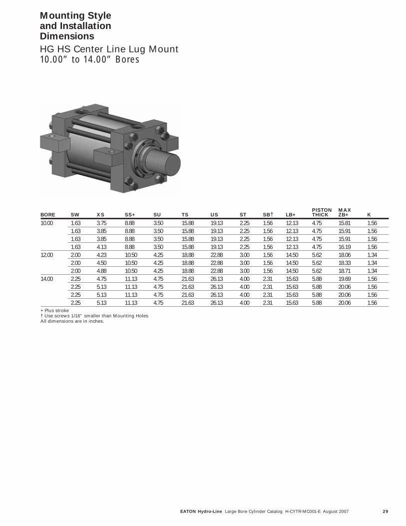
Mounting Style and Installation Dimensions
HG HS Center Line Lug Mount10.00” to 14.00” Bores
ØBØRM
4 x ØSB †
FVC
WF
ØMM
TS
US
3
4 2
ST
SWSUSUSS + Stroke
SWXS
ZB + Stroke
SQ.E
1J
LB + StrokeG K
See RodEnd Pages
ROD DIA BBORE MM +.000/-.005 RM C E F V WF G J
10.00 4.50 5.249 7.00 1.00 12.62 0.88 0.25 2.13 3.69 3.695.00 5.749 7.50 1.00 12.62 0.98 0.25 2.23 3.69 3.695.50 6.249 8.00 1.00 12.62 0.98 0.25 2.23 3.69 3.697.00 7.999 9.69 1.00 12.62 1.13 0.38 2.50 3.69 3.69
12.00 5.50 6.249 8.00 1.00 14.88 0.98 0.25 2.23 4.44 4.447.00 7.999 9.69 1.00 14.88 1.13 0.38 2.50 4.44 4.448.00 8.999 10.69 1.00 14.88 1.50 0.38 2.88 4.44 4.44
14.00 7.00 7.999 9.69 1.00 17.13 1.13 0.38 2.50 4.88 4.888.00 8.999 10.69 1.00 17.13 1.50 0.38 2.88 4.88 4.889.00 9.999 11.69 1.00 17.13 1.50 0.38 2.88 4.88 4.8810.00 10.999 12.69 1.00 17.13 1.50 0.38 2.88 4.88 4.88
29EATON Hydro-Line Large Bore Cylinder Catalog H-CYTR-MC001-E August 2007
Mounting Style and Installation Dimensions
HG HS Center Line Lug Mount10.00” to 14.00” Bores
PISTON MAXBORE SW XS SS+ SU TS US ST SB† LB+ THICK ZB+ K
10.00 1.63 3.75 8.88 3.50 15.88 19.13 2.25 1.56 12.13 4.75 15.81 1.561.63 3.85 8.88 3.50 15.88 19.13 2.25 1.56 12.13 4.75 15.91 1.561.63 3.85 8.88 3.50 15.88 19.13 2.25 1.56 12.13 4.75 15.91 1.561.63 4.13 8.88 3.50 15.88 19.13 2.25 1.56 12.13 4.75 16.19 1.56
12.00 2.00 4.23 10.50 4.25 18.88 22.88 3.00 1.56 14.50 5.62 18.06 1.342.00 4.50 10.50 4.25 18.88 22.88 3.00 1.56 14.50 5.62 18.33 1.342.00 4.88 10.50 4.25 18.88 22.88 3.00 1.56 14.50 5.62 18.71 1.34
14.00 2.25 4.75 11.13 4.75 21.63 26.13 4.00 2.31 15.63 5.88 19.69 1.562.25 5.13 11.13 4.75 21.63 26.13 4.00 2.31 15.63 5.88 20.06 1.562.25 5.13 11.13 4.75 21.63 26.13 4.00 2.31 15.63 5.88 20.06 1.562.25 5.13 11.13 4.75 21.63 26.13 4.00 2.31 15.63 5.88 20.06 1.56
+ Plus stroke† Use screws 1/16” smaller than Mounting HolesAll dimensions are in inches.

30 EATON Hydro-Line Large Bore Cylinder Catalog H-CYTR-MC001-E August 2007
CFV
WF
ØMM
K
ØRMSQ.E
ØB
4
3
1
2
H
BB
G J
DD
ZJ + Stroke
LB + Stroke
See RodEnd Pages
Mounting Style and Installation Dimensions
HG NS Cap End ExtendedTie Rod Mount10.00” to 14.00” Bores
ROD DIA BBORE MM +.000/-.005 RM C E F V WF G J
10.00 4.50 5.249 7.00 1.00 12.62 0.88 0.25 2.13 3.69 3.695.00 5.749 7.50 1.00 12.62 0.98 0.25 2.23 3.69 3.695.50 6.249 8.00 1.00 12.62 0.98 0.25 2.23 3.69 3.697.00 7.999 9.69 1.00 12.62 1.13 0.38 2.50 3.69 3.69
12.00 5.50 6.249 8.00 1.00 14.88 0.98 0.25 2.23 4.44 4.447.00 7.999 9.69 1.00 14.88 1.13 0.38 2.50 4.44 4.448.00 8.999 10.69 1.00 14.88 1.50 0.38 2.88 4.44 4.44
14.00 7.00 7.999 9.69 1.00 17.13 1.13 0.38 2.50 4.88 4.888.00 8.999 10.69 1.00 17.13 1.50 0.38 2.88 4.88 4.889.00 9.999 11.69 1.00 17.13 1.50 0.38 2.88 4.88 4.8810.00 10.999 12.69 1.00 17.13 1.50 0.38 2.88 4.88 4.88
Note: For Tie Rod coordinates and torque values, refer to page 46.

31EATON Hydro-Line Large Bore Cylinder Catalog H-CYTR-MC001-E August 2007
Mounting Style and Installation Dimensions
HG NS Cap End ExtendedTie Rod Mount10.00” to 14.00” Bores
DD PISTONBORE (UN THDS.) BB H LB+ THICK ZJ+ K
10.00 1.500-12 5.19 1.32 12.13 4.75 14.25 1.561.500-12 5.19 1.32 12.13 4.75 14.35 1.561.500-12 5.19 1.32 12.13 4.75 14.35 1.561.500-12 5.19 1.32 12.13 4.75 14.63 1.56
12.00 1.250-12 5.69 1.09 14.50 5.62 16.72 1.341.250-12 5.69 1.09 14.50 5.62 17.00 1.341.250-12 5.69 1.09 14.50 5.62 17.37 1.34
14.00 1.500-12 6.38 1.32 15.63 5.88 18.13 1.561.500-12 6.38 1.32 15.63 5.88 18.50 1.561.500-12 6.38 1.32 15.63 5.88 18.50 1.561.500-12 6.38 1.32 15.63 5.88 18.50 1.56
+ Plus strokeAll dimensions are in inches.

32 EATON Hydro-Line Large Bore Cylinder Catalog H-CYTR-MC001-E August 2007
See RodEnd Pages
BB
ØMM
SQ.E
4
ØRMØB
3
DD
1
2
J
ZB + Stroke
LB + Stroke
C
V
G
WF
H
F
K
Mounting Style and Installation Dimensions
HG MS Head EndExtended Tie Rod Mount10.00” to 14.00” Bores
ROD DIA BBORE MM +.000/-.005 RM C E F V WF G J
10.00 4.50 5.249 7.00 1.00 12.62 0.88 0.25 2.13 3.69 3.695.00 5.749 7.50 1.00 12.62 0.98 0.25 2.23 3.69 3.695.50 6.249 8.00 1.00 12.62 0.98 0.25 2.23 3.69 3.697.00 7.999 9.69 1.00 12.62 1.13 0.38 2.50 3.69 3.69
12.00 5.50 6.249 8.00 1.00 14.88 0.98 0.25 2.23 4.44 4.447.00 7.999 9.69 1.00 14.88 1.13 0.38 2.50 4.44 4.448.00 8.999 10.69 1.00 14.88 1.50 0.38 2.88 4.44 4.44
14.00 7.00 7.999 9.69 1.00 17.13 1.13 0.38 2.50 4.88 4.888.00 8.999 10.69 1.00 17.13 1.50 0.38 2.88 4.88 4.889.00 9.999 11.69 1.00 17.13 1.50 0.38 2.88 4.88 4.8810.00 10.999 12.69 1.00 17.13 1.50 0.38 2.88 4.88 4.88
Note: For Tie Rod coordinates and torque values, refer to page 46.

33EATON Hydro-Line Large Bore Cylinder Catalog H-CYTR-MC001-E August 2007
Mounting Style and Installation Dimensions
HG MS Head EndExtended Tie Rod Mount10.00” to 14.00” Bores
DD PISTONBORE (UN THDS.) BB H LB+ THICK ZB+ K
10.00 1.500-12 5.19 1.32 12.13 4.75 15.81 1.561.500-12 5.19 1.32 12.13 4.75 15.94 1.561.500-12 5.19 1.32 12.13 4.75 15.91 1.561.500-12 5.19 1.32 12.13 4.75 16.19 1.56
12.00 1.250-12 5.69 1.09 14.50 5.62 18.06 1.341.250-12 5.69 1.09 14.50 5.62 18.33 1.341.250-12 5.69 1.09 14.50 5.62 18.71 1.34
14.00 1.500-12 6.38 1.32 15.63 5.88 19.69 1.561.500-12 6.38 1.32 15.63 5.88 20.06 1.561.500-12 6.38 1.32 15.63 5.88 20.06 1.561.500-12 6.38 1.32 15.63 5.88 20.06 1.56
+ Plus strokeAll dimensions are in inches.
34 EATON Hydro-Line Large Bore Cylinder Catalog H-CYTR-MC001-E August 2007
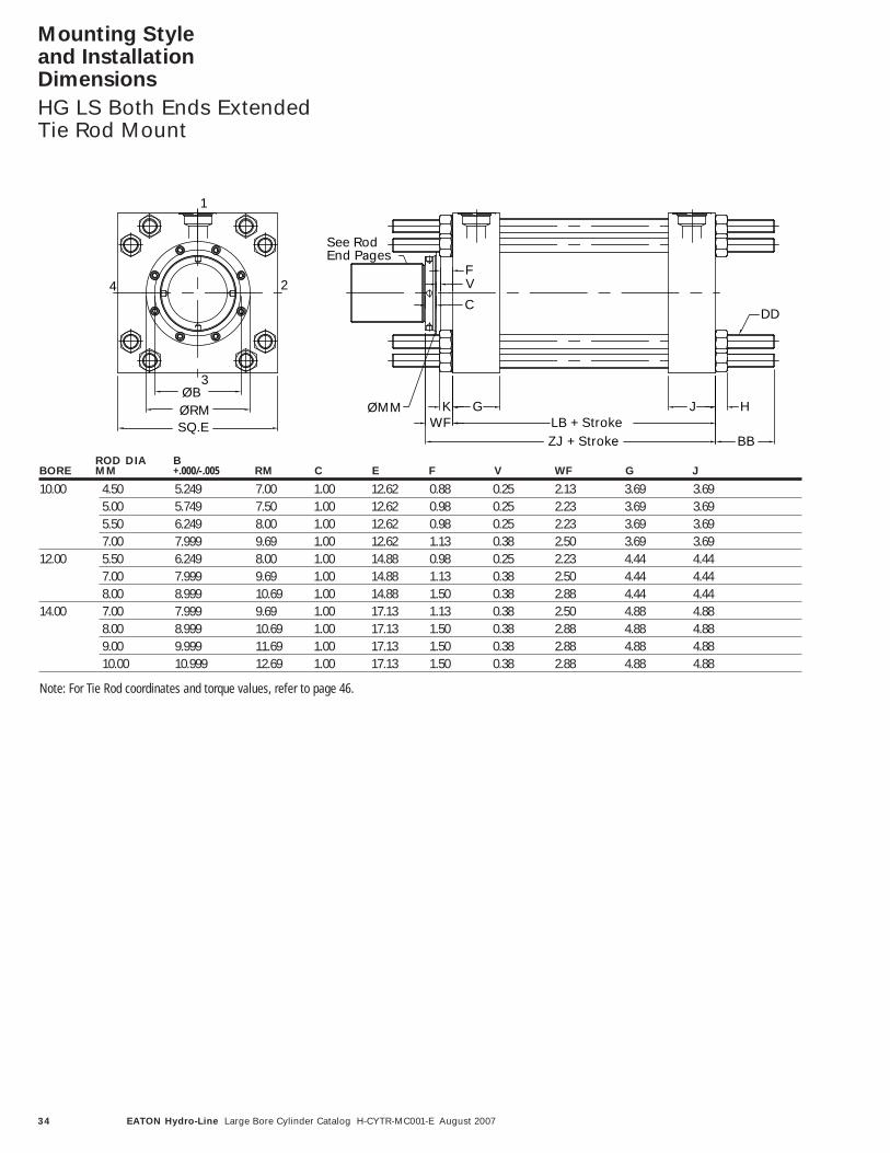
Mounting Style and Installation Dimensions
HG LS Both Ends ExtendedTie Rod Mount
C
WFK
VF
ZJ + StrokeSQ.E
ØBØRM
4
3
ØMM
1
2
BB
HLB + Stroke
G J
DD
See RodEnd Pages
ROD DIA BBORE MM +.000/-.005 RM C E F V WF G J
10.00 4.50 5.249 7.00 1.00 12.62 0.88 0.25 2.13 3.69 3.695.00 5.749 7.50 1.00 12.62 0.98 0.25 2.23 3.69 3.695.50 6.249 8.00 1.00 12.62 0.98 0.25 2.23 3.69 3.697.00 7.999 9.69 1.00 12.62 1.13 0.38 2.50 3.69 3.69
12.00 5.50 6.249 8.00 1.00 14.88 0.98 0.25 2.23 4.44 4.447.00 7.999 9.69 1.00 14.88 1.13 0.38 2.50 4.44 4.448.00 8.999 10.69 1.00 14.88 1.50 0.38 2.88 4.44 4.44
14.00 7.00 7.999 9.69 1.00 17.13 1.13 0.38 2.50 4.88 4.888.00 8.999 10.69 1.00 17.13 1.50 0.38 2.88 4.88 4.889.00 9.999 11.69 1.00 17.13 1.50 0.38 2.88 4.88 4.8810.00 10.999 12.69 1.00 17.13 1.50 0.38 2.88 4.88 4.88
Note: For Tie Rod coordinates and torque values, refer to page 46.

35EATON Hydro-Line Large Bore Cylinder Catalog H-CYTR-MC001-E August 2007
Mounting Style and Installation Dimensions
HG LS Both Ends ExtendedTie Rod Mount
DD PISTONBORE (UN THDS.) BB H LB+ THICK ZJ+ K
10.00 1.500-12 5.19 1.32 12.13 4.75 14.25 1.561.500-12 5.19 1.32 12.13 4.75 14.35 1.561.500-12 5.19 1.32 12.13 4.75 14.35 1.561.500-12 5.19 1.32 12.13 4.75 14.63 1.56
12.00 1.250-12 5.69 1.09 14.50 5.62 16.72 1.341.250-12 5.69 1.09 14.50 5.62 17.00 1.341.250-12 5.69 1.09 14.50 5.62 17.37 1.34
14.00 1.500-12 6.38 1.32 15.63 5.88 18.13 1.561.500-12 6.38 1.32 15.63 5.88 18.50 1.561.500-12 6.38 1.32 15.63 5.88 18.50 1.561.500-12 6.38 1.32 15.63 5.88 18.50 1.56
+ Plus strokeAll dimensions are in inches.

36 EATON Hydro-Line Large Bore Cylinder Catalog H-CYTR-MC001-E August 2007
Mounting Style and Installation Dimensions
HG Double Rod End
MOUNT HG MOUNT CODE
Side Lug ADHead Square JDHead Rectangular GDIntermediate Trunnion TDHead Trunnion UDCenter Line Lug Mount HDHead End Extended Tie Rod MDBoth End Extended Tie Rod LDNo Mount KD
BORE MM LD ZM
10.00 4.50 12.13 16.3810.00 5.00 12.13 16.3810.00 5.50 12.13 16.3810.00 7.00 12.13 17.1312.00 5.50 14.50 18.9512.00 7.00 14.50 19.5012.00 8.00 14.50 20.2514.00 7.00 15.63 20.6314.00 8.00 15.63 21.3814.00 9.00 15.63 21.3814.00 10.00 15.63 21.3816.00 8.00 18.63 24.3816.00 9.00 18.63 24.3816.00 10.00 18.63 24.3818.00 9.00 21.63 27.3818.00 10.00 21.63 27.3820.00 10.00 24.63 30.38
NOTES:1) Dimensions shown are supplement
to single rod end cylinders.
2) If only one end cushioning isrequired, clearly indicate whichis required.
3) Mount offerings and pressure rat-ings remain same as single rodcylinders.
4)† Use screws 1/16” smaller thanmounting holes.
ZM + 2x StrokeWF
XSSW
RM
ØMM
US
SQ.E TS
B 4 X Ø SB†
E/2
ST
-.005-.010
Rod End # 1
SWK
SV + StrokeSU SU
G G
LD + Stroke
Rod End # 2
37EATON Hydro-Line Large Bore Cylinder Catalog H-CYTR-MC001-E August 2007
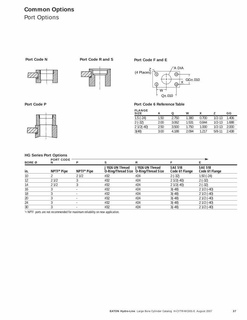
Port Code R and SPort Code N
Port Code P
Port Code F and E
Port Code 6 Reference Table
Z A DIA
X
W
GG±.010
Q±.010
(4 Places)
HG Series Port OptionsPORT CODE
BORE Ø N P S R F E
J1926 UN Thread J1926 UN Thread SAE 518 SAE 518in. NPTF* Pipe NPTF* Pipe O-Ring/Thread Size O-Ring/Thread Size Code 61 Flange Code 61 Flange10 2 2 1/2 #32 #24 2 (-32) 1.50 (-24)12 2 1/2 3 #32 #24 2 1/2(-40) 2 (-32)14 2 1/2 3 #32 #24 2 1/2(-40) 2 (-32)16 3 - #32 #24 3(-48) 2 1/2 (-40)18 3 - #32 #24 3(-48) 2 1/2 (-40)20 3 - #32 #24 3(-48) 2 1/2 (-40)24 3 - #32 #24 3(-48) 2 1/2 (-40)30 3 - #32 #24 3(-48) 2 1/2 (-40)'+ NPTF ports are not recommended for maximum reliability on new application.
Common Options
Port Options
FLANGESIZE A Q W X Z GG
1.5 (-24) 1.50 2.750 1.380 0.700 1/2-13 1.4062 (-32) 2.00 3.062 1.531 0.844 1/2-13 1.6882 1/2(-40) 2.50 3.500 1.750 1.000 1/2-13 2.0003(48) 3.00 4.188 2.094 1.217 5/8-11 2.438

38 EATON Hydro-Line Large Bore Cylinder Catalog H-CYTR-MC001-E August 2007
Common Options
Rod End Selection
Type #2 Small Male UN Thread
Type #4 Short Female UNF Thread
Type #5 Plain - No Attachment
Type #G Grooved Rod End
Type #K Extended SmallMale UN Thread
Type #1 Intermediate MaleUN Thread
Type #M Extended Int. Male UN Thread
In addition to selecting thecorrect bore, you mustspecify the appropriate rodsize and rod end configurationfor your application.
Seven different inch rod endconfigurations are available.If a custom design isrequired, contact your localEaton Hydro-Line sales engi-neer, and we will build toyour requirements.
The table on page 49 givesmaximum allowable lengthbetween the mountingpoints at various operatingpressures for available roddiameters of Series HGcylinders.
Rod ends on rigid mountcylinders should be supported.Longer strokes are allowablefor pull only applications.Contact your local EatonHydro-Line sales engineerfor application assistance if necessary.
CV
ØMM
Ø.05 Spanner Hole
A
KK
CV
Ø.05 Spanner Hole
A
KK
V 1.000.25
30ºAD
AE
V
ØAF
AC
CV
Ø.05 Spanner Hole
AX
KK
CV
Ø.05 Spanner Hole
A
CC
CV
Ø.05 Spanner Hole
AX
CC
ROD SIZEMM A AX KK CC AC AD AE AF
4.50 4.50 9.00 3.250-12 4.250-12 5.25 3.19 1.50 3.505.00 5.00 10.00 3.500-12 4.750-12 5.38 3.19 1.50 3.885.50 5.50 11.00 4.000-12 5.250-12 6.25 3.94 1.88 4.387.00 7.00 14.00 5.500-12 6.500-12 6.50 4.06 2.00 5.758.00 8.00 16.00 6.000-12 7.500-12 6.50 4.06 2.00 6.509.00 9.00 18.00 6.500-12 8.500-12 6.75 4.13 2.00 7.2510.00 10.00 20.00 7.500-12 9.000-12 7.25 4.63 2.38 8.0011.00 11.00 22.00 8.000-8 - - - -14.00 14.00 28.00 11.000-8 - - - -
NOTES:1) Dimensions in inches.
39EATON Hydro-Line Large Bore Cylinder Catalog H-CYTR-MC001-E August 2007
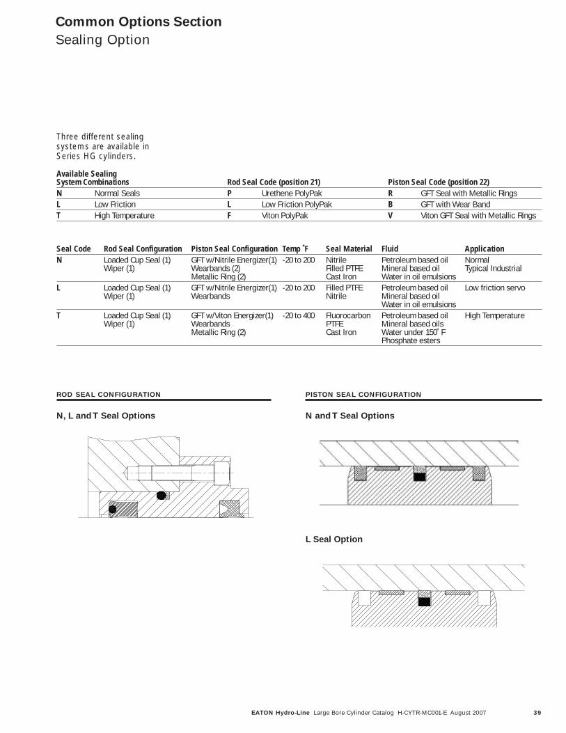
Common Options Section
Sealing Option
Seal Code Rod Seal Configuration Piston Seal Configuration Temp ˚F Seal Material Fluid ApplicationN Loaded Cup Seal (1) GFT w/Nitrile Energizer(1) -20 to 200 Nitrile Petroleum based oil Normal
Wiper (1) Wearbands (2) Filled PTFE Mineral based oil Typical IndustrialMetallic Ring (2) Cast Iron Water in oil emulsions
L Loaded Cup Seal (1) GFT w/Nitrile Energizer(1) -20 to 200 Filled PTFE Petroleum based oil Low friction servoWiper (1) Wearbands Nitrile Mineral based oil
Water in oil emulsionsT Loaded Cup Seal (1) GFT w/Viton Energizer(1) -20 to 400 Fluorocarbon Petroleum based oil High Temperature
Wiper (1) Wearbands PTFE Mineral based oilsMetallic Ring (2) Cast Iron Water under 150˚ F
Phosphate esters
ROD SEAL CONFIGURATION
N, L and T Seal Options
L Seal Option
PISTON SEAL CONFIGURATION
N and T Seal Options
Available SealingSystem Combinations Rod Seal Code (position 21) Piston Seal Code (position 22)N Normal Seals P Urethene PolyPak R GFT Seal with Metallic RingsL Low Friction L Low Friction PolyPak B GFT with Wear BandT High Temperature F Viton PolyPak V Viton GFT Seal with Metallic Rings
Three different sealing systems are available inSeries HG cylinders.

40 EATON Hydro-Line Large Bore Cylinder Catalog H-CYTR-MC001-E August 2007
MOUNTING HEAD LOCATION CAP LOCATIONSTYLE CODE DESCRIPTION 1 2 3 4 1 2 3 4
AS Side Lug A A A A A A A AJS Head Square A A A A A A A AGS Head Rectangular A A A A A A A ACF Cap Clevis A A A A A A A ASS Cap Square A A A A A A A APS Cap Rectangular A A A A A A A ATT Intermediate Trunnion A A A A A A A AWS Cap Trunnion A A A A A N A NUS Head Trunnion A N A N A A A AHS Center Line Lug A N A N A N A NKS No Mount A A A A A A A AAD Double Rod Side Lug A A N AGD Double Rod Rectangular A A A ATD Double Rod Intermediate Trunnion A A A AKD Double Rod No Mount A A A A
Common Options
Port and CushionSelection
Port and cushion locationsare identified by viewing thecylinder from the head end(or from the mounting endof double rod cylinder). Thelocation numbers are shownto the right.
Certain port and cushionlocations cannot be specifiedwith some mounting styles.The table below indicateswhich of the head and capport location are available foreach Series HG mountingstyle.
Port Location Availability Chart
Cushion Availability Chart
MOUNTING HEAD LOCATION CAP LOCATIONSTYLE CODE DESCRIPTION 1 2 3 4 1 2 3 4
AS Side Lug A A A A A A A AJS Head Square A A A A A A A AGS Head Rectangular A N A N A A A ACF Cap Clevis A A A A A A A ASS Cap Square A A A A N N N NPS Cap Rectangular A A A A A N A NTT Intermediate Trunnion A A A A A A A AWS Cap Trunnion A A A A A N A NUS Head Trunnion A N A N A A A AHS Center Line Lug A N A N A N A NKS No Mount A A A A A A A AAD Double Rod Side Lug A A A AGD Double Rod Rectangular A N A NTD Double Rod Intermediate Trunnion A A A AKD Double Rod No Mount A A A AA- Available N- Not available
A- Available N- Not available
1
2
3
4

41EATON Hydro-Line Large Bore Cylinder Catalog H-CYTR-MC001-E August 2007
CYLINDER STATICBORE ROD PART TENSILEDIA. DIA. NUMBER CB CD BD E F FL LR M MR BA A B AA LOAD(LB)
10.00 4.50 HG-1052-10 4.00 3.50 1.78 12.63 1.69 5.69 3.50 3.50 3.50 9.62 - - 13.60 6000012.00 5.50 HG-1252-10 4.50 4.00 2.03 14.88 1.94 6.44 3.88 3.88 4.00 11.50 - - 16.20 7500014.00 7.00 HG-1452-10 6.00 5.00 1.03 17.25 2.19 7.94 5.00 5.00 5.25 14.41 27.60 11.60 17.31 9565016.00 8.00 HG-1652-10 7.00 6.00 1.28 20.00 2.63 9.38 5.50 6.00 6.25 17.50 22.50 15.00 19.00 187500Note: 1. The load is maximum load in tension
2. The pull load of the cylinder should be less than the listed load for the respective selected rod accessory.3. Pivot pin is rated in shear.4. All rod accessories must be torqued against rod shoulder.
CYL. STATICBORE ROD PART TENSILEDIA. DIA. NUMBER CB CD CE CH CW ER L KK LOAD(LB)
10.00 4.50 HG-1062-10 4.00 3.50 8.50 5.00 2.00 3.50 4.00 3.250-12 14250012.00 5.50 HG-1262-10 4.50 4.00 10.00 6.13 2.25 4.00 4.50 4.000-12 18250014.00 7.00 HG-1462-10 6.00 5.00 12.75 - 3.00 5.25 5.75 5.500-12 30000016.00 8.00 HG-1662-10 7.00 6.00 15.75 - 3.50 6.25 6.75 6.000-12 390000
CYL. STATICBORE ROD PART TENSILEDIA. DIA. NUMBER A CA CB CD ER KK LOAD(LB)
10.00 4.50 HG-1060 4.50 7.63 4.00 3.50 3.88 3.250-12 15820012.00 5.50 HG-1260 5.50 9.13 4.50 4.00 4.44 4.000-12 21150014.00 7.00 HG-1460 7.00 11.75 6.00 5.00 5.25 5.500-12 33750016.00 8.00 HG-1660 9.00 14.25 7.00 6.00 6.25 6.000-12 450000
CYL. STATICBORE PART TENSILEDIA. NUMBER CD CL CP LOAD(LB)
10.00 HG-1083-10 3.50 8.00 9.63 40177512.00 HG-1283-10 4.00 9.00 10.63 52475014.00 HG-1483-10 5.00 12.00 13.63 81995016.00 HG-1683-10 6.00 14.00 15.63 1180725Note: 1. CL = 2 x CW + CB
Recommended TorqueValues
Using MOS2 lubricant with.12 coefficient of friction.
For accessories above 18inch, please consult factory.
BD Dia (4) Holes
BD Dia (20) Holes
CB CB
BA
BA2
AA
AAAº Bº Typ.
CD
MR
MRM LR
LR
FL FLF F+.004+.002
CD+.004+.002
ESQ
EBA SQ
SQ
THREAD TORQUESIZE (FT-LBS)
3.250-12 7.9404.000-12 12.5605.500-12 16.2756.000-12 21.600
All rod accessories must betorqued against the rodshoulder. Mounting brack-ets, rod clevises and rodeyes are available fromEaton. These accessoriesare detailed below showing
part numbers and all the per-tinent dimensional data.Make sure the rod end typeselected has threads thatmatch the threads of anyrequired accessory.
MountingAccessories
Accessories
Up to 10.00 & 12.00 Bores 14.00 & 16.00 Bores
Pivot Clevis
Eye Bracket
Pivot Pin
Rod Eye
ER CD CD
CD
CA
CB
KK TAP
A
CD+.004+.002
CD CLCP
CE
CW CWCB
L
ERRadius
KK Tap CH HexAcross Flats
CD+.004+.002

42 EATON Hydro-Line Large Bore Cylinder Catalog H-CYTR-MC001-E August 2007
PART ROD MAX PULLNUMBER DIA A B C D F G H J K KK AT YIELD
AC-2-36 41/2 41/2 6 77/8 1 415/32 ▲ 43/4 51/4-12UN 15/8 31/4-12 475,500AC-2-44 51/2 51/2 71/4 93/8 1 515/32 ▲ 53/4 61/2-12UN 17/8 4-12 750,010▲ Four 1/2” diameter x 1/2” deep spanner holes instead of flats.
MountingAccessories
Self-AligningCoupler
Lateral movement (on pushonly) and radial movementprovide precision alignmentbetween cylinder andmachine. Couplers presetwith proper clearances andcompletely lubricated at factory before shipping.
1/32"Lateral
Piston Rod
Across FlatsH
B
GAcross(4) Flats
Jam nut
KK TapA Depth
(MIN)
1/32(Float)
C(Min)
A
KK THD F
J ThreadKD
Note
When ordering oversize and2:1 rod cylinders, specifymodification to suit standardrod diameter’s coupler.
Self-aligning Coupler
Self-aligning Rod End Coupler

43EATON Hydro-Line Large Bore Cylinder Catalog H-CYTR-MC001-E August 2007
MountingAccessories
Grooved RodEnd Coupling
Quick connect- disconnect coupling
Weld-plate
Locatorpin
Machinemember
SMMDN
CAF
A A
B
L
MOUNT -05
S HE DIA.F # BOLTS
G DIA.B.C.
U
MOUNT -08, -11
S
THE DIA.
F NO. BOLTS
G DIA B.C.
T
S
MOUNT -14, -20, -36
S
THE DIA.
F NO. BOLTS
G DIA.B.C.
SS
H
G DIA.B.C.
S
G DIA. B.C.MOUNT-16, -24, -28, -32,-40, -44, -56, -72
TU TU
E DIA.F NO.BOLTS
TUX
STUX E DIA.F# BOLTS
MOUNT -64, -80
Typical section AAdepending on rod diameter
H
C-272-Weld PlateP DIA.
Locator Pin
C-271-Coupling
K
ROD WELD WELD SOC.CPLNG DIA PLATE HD CAP TORQ.C-271- MM AF B C D E F G H K C-272- L N P SCREWS FT/LB S T U X
C-271-36 4.500 3.50 2.38 3.62 6.88 .781 8 5.69 22º 30’ 1.12 C-272-36 1.25 7.50 .38 1/4-10 x 3.5 450 1.088 2.627 - -C-271-40 5.000 3.88 2.50 4.00 7.38 .656 12 6.18 15º 1.25 C-272-40 1.38 8.00 .38 5/8-11x3.75 255 .801 2.188 2.988 -C-271-44 5.500 4.38 3.12 4.50 8.25 .781 12 6.88 15º 1.38 C-272-44 1.50 9.00 .38 3/4-10x4.5 450 .890 2.431 3.320 -C-271-56 7.000 5.75 4.00 5.94 10.38 1.031 12 8.75 15º 1.50 C-272-56 1.75 11.00 .50 1-8x5.5 1090 1.132 3.094 4.226 -C-271-64 8.000 6.50 4.00 6.69 11.38 1.031 16 9.75 11º 15’ 1.50 C-272-64 2.00 12.00 .50 1-8x5.5 1090 .951 2.708 4.053 4.781C-271-72 9.000 7.25 4.00 7.50 13.12 1.281 12 11.12 15º 2.00 C-272-72 2.25 14.00 .50 11/4-7x6 2180 1.440 3.933 5.373 -C-271-80 10.000 8.00 4.50 8.25 14.12 1.281 16 12.12 11º 15’ 2.00 C-272-80 2.50 15.00 .50 11/4-7x6.5 2180 1.183 3.368 5.040 5.946To order C-271-_ and C-272-_ as an assembly, sue part no. C-275-_.
The two-piece steel couplingfeatures high tensile strengthsocket head cap screws(with safety factor designed to take full load), permitsquick assembly / disassemblyfor fast and easy installationand servicing.
Used with the Hydro-Linestyle G rod end, the rod endcoupling provides for closelateral alignment betweenthe rod end and machinemember.
44 EATON Hydro-Line Large Bore Cylinder Catalog H-CYTR-MC001-E August 2007
Application/Engineering Data
Stop Tube Selection
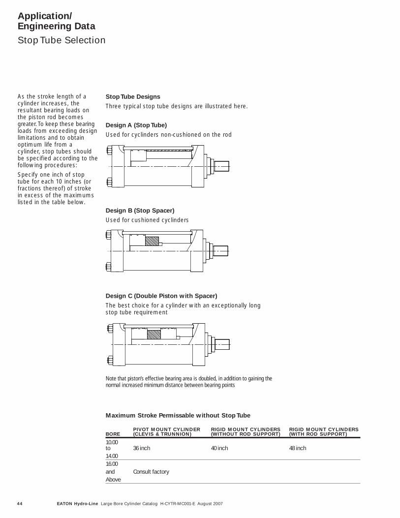
As the stroke length of acylinder increases, theresultant bearing loads onthe piston rod becomesgreater. To keep these bearingloads from exceeding designlimitations and to obtainoptimum life from a cylinder, stop tubes shouldbe specified according to thefollowing procedures:
Specify one inch of stoptube for each 10 inches (orfractions thereof) of strokein excess of the maximumslisted in the table below.
Stop Tube Designs
Three typical stop tube designs are illustrated here.
Design A (Stop Tube)
Used for cyclinders non-cushioned on the rod
Design B (Stop Spacer)
Used for cushioned cyclinders
Design C (Double Piston with Spacer)
The best choice for a cylinder with an exceptionally longstop tube requirement
Note that piston’s effective bearing area is doubled, in addition to gaining thenormal increased minimum distance between bearing points
Maximum Stroke Permissable without Stop Tube
Through Tie rods
Tapped Tie rods Mounting lug similarto Style VG01
Through Tie rods
Tapped Tie rods Mounting lug similarto Style VG01
Through Tie rods
Tapped Tie rods Mounting lug similarto Style VG01
PIVOT MOUNT CYLINDER RIGID MOUNT CYLINDERS RIGID MOUNT CYLINDERSBORE (CLEVIS & TRUNNION) (WITHOUT ROD SUPPORT) (WITH ROD SUPPORT)
10.00to 36 inch 40 inch 48 inch14.0016.00and Consult factoryAbove

45EATON Hydro-Line Large Bore Cylinder Catalog H-CYTR-MC001-E August 2007
Application/Engineering Data
Tie Rod SpacerSelection
Tie rod spacers and centersupports are used toimprove the structural rigidityof long stroke tie rod cylinders.A tie rod spacer or centersupport should be appliedwhen the stroke lengthexceeds 20 times the borediameter.
Tie Rod Spacer
The spacers have throughholes for the tie rods and areheld in place on the cylinderbarrel with a small tack weldor set screw. The spacerskeeps the tie rod in the proper position around thecenterline of the cylinder and acts much like a truss in preventing excessivedeflection in a long strokecylinder that is not rigidlymounted (Clevis mount etc.).
Tie Rod Center Support
The center support has sidemounting lugs similar to sidelug mount heads and servesas as additional mountinglocation. The tie rods arestudded in to the centersupport and it becomes aload carrying component ofthe cylinder assembly. Theexact location of the tie rodcenter support is generallyoptional, which greatlyincreases the flexibility inmounting a long stroke cylinder.
Through Tie Rods
Tapped Tie Rods Mounting Lug similarto Style HG AS
46 EATON Hydro-Line Large Bore Cylinder Catalog H-CYTR-MC001-E August 2007
Application/Engineering Data
PS200 Proximity Switch
PS200 Proximity Switches
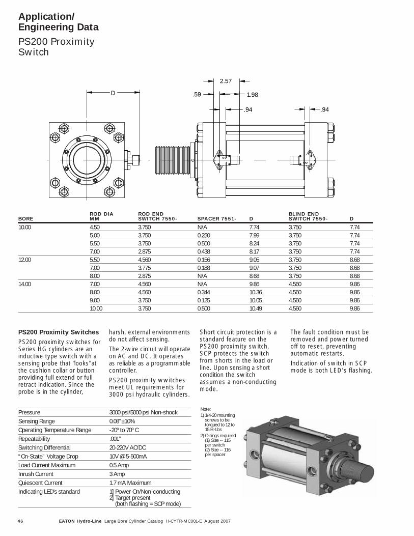
PS200 proximity switches forSeries HG cylinders are aninductive type switch with asensing probe that "looks"atthe cushion collar or buttonproviding full extend or fullretract indication. Since theprobe is in the cylinder,
harsh, external environmentsdo not affect sensing.
The 2-wire circuit will operateon AC and DC. It operatesas reliable as a programmablecontroller.
PS200 proximity wwitchesmeet UL requirements for3000 psi hydraulic cylinders.
Short circuit protection is astandard feature on thePS200 proximity switch.SCP protects the switchfrom shorts in the load orline. Upon sensing a shortcondition the switchassumes a non-conductingmode.
The fault condition must beremoved and power turnedoff to reset, preventing automatic restarts.
Indication of switch in SCPmode is both LED's flashing.
1.98
2.57
.59D
.94 .94
ROD DIA ROD END BLIND ENDBORE MM SWITCH 7550- SPACER 7551- D SWITCH 7550- D
10.00 4.50 3.750 N/A 7.74 3.750 7.745.00 3.750 0.250 7.99 3.750 7.745.50 3.750 0.500 8.24 3.750 7.747.00 2.875 0.438 8.17 3.750 7.74
12.00 5.50 4.560 0.156 9.05 3.750 8.687.00 3.775 0.188 9.07 3.750 8.688.00 2.875 N/A 8.68 3.750 8.68
14.00 7.00 4.560 N/A 9.86 4.560 9.868.00 4.560 0.344 10.36 4.560 9.869.00 3.750 0.125 10.05 4.560 9.8610.00 3.750 0.500 10.49 4.560 9.86
Pressure 3000 psi/5000 psi Non-shockSensing Range 0.08”±10%Operating Temperature Range -20º to 70º CRepeatability .001”Switching Differential 20-220V AC/DC“On-State” Voltage Drop 10V @ 5-500mALoad Current Maximum 0.5 AmpInrush Current 3 AmpQuiescent Current 1.7 mA MaximumIndicating LED’s standard 1] Power On/Non-conducting
2] Target present(both flashing = SCP mode)
Note: 1) 1/4-20 mounting
screws to betorqued to 12 to15 Ft-Lbs
2) O-rings required(1) Size -- 115per switch(2) Size -- 116per spacer
47EATON Hydro-Line Large Bore Cylinder Catalog H-CYTR-MC001-E August 2007
Application/Engineering Data
Limit Switches(Available up to 14” Bore)
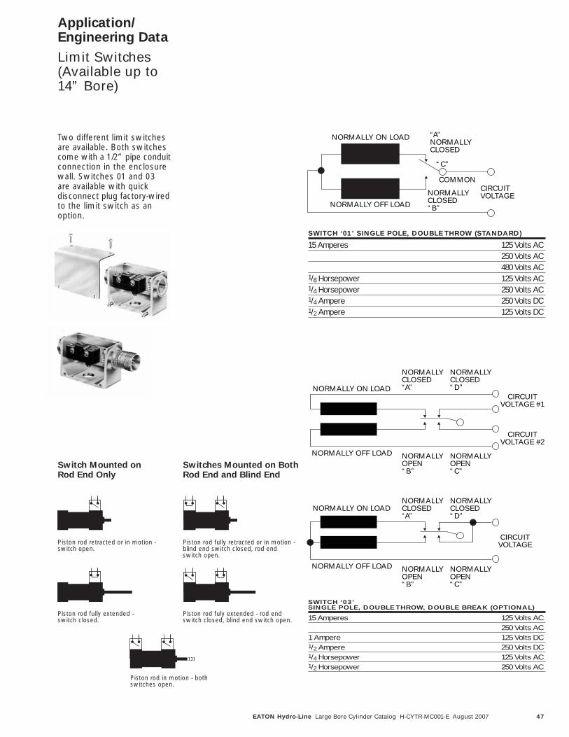
SWITCH ‘01’ SINGLE POLE, DOUBLE THROW (STANDARD)
15 Amperes 125 Volts AC250 Volts AC480 Volts AC
1/8 Horsepower 125 Volts AC1/4 Horsepower 250 Volts AC1/4 Ampere 250 Volts DC1/2 Ampere 125 Volts DC
SWITCH ‘03’SINGLE POLE, DOUBLE THROW, DOUBLE BREAK (OPTIONAL)
15 Amperes 125 Volts AC250 Volts AC
1 Ampere 125 Volts DC1/2 Ampere 250 Volts DC1/4 Horsepower 125 Volts AC1/2 Horsepower 250 Volts AC
CIRCUITVOLTAGE #1
CIRCUITVOLTAGE #2
NORMALLY ON LOAD
NORMALLY OFF LOAD
NORMALLY CLOSED“A”
NORMALLY CLOSED“D”
NORMALLY OPEN“B”
NORMALLY OPEN“C”
CIRCUITVOLTAGE
NORMALLY ON LOAD
NORMALLY OFF LOAD
NORMALLY CLOSED“A”
NORMALLY CLOSED“D”
NORMALLY OPEN“B”
NORMALLY OPEN“C”
“A”NORMALLY CLOSED
NORMALLY CLOSED“B”
CIRCUITVOLTAGE
“C”
COMMON
NORMALLY ON LOAD
NORMALLY OFF LOAD
Two different limit switchesare available. Both switchescome with a 1/2” pipe conduitconnection in the enclosurewall. Switches 01 and 03 are available with quick disconnect plug factory-wiredto the limit switch as anoption.
Switch Mounted on Rod End Only
Switches Mounted on BothRod End and Blind End
Piston rod retracted or in motion -switch open.
Piston rod fully extended - switch closed.
Piston rod in motion - both switches open.
Piston rod fuly extended - rod endswitch closed, blind end switch open.
Piston rod fully retracted or in motion -blind end switch closed, rod end switch open.
48 EATON Hydro-Line Large Bore Cylinder Catalog H-CYTR-MC001-E August 2007
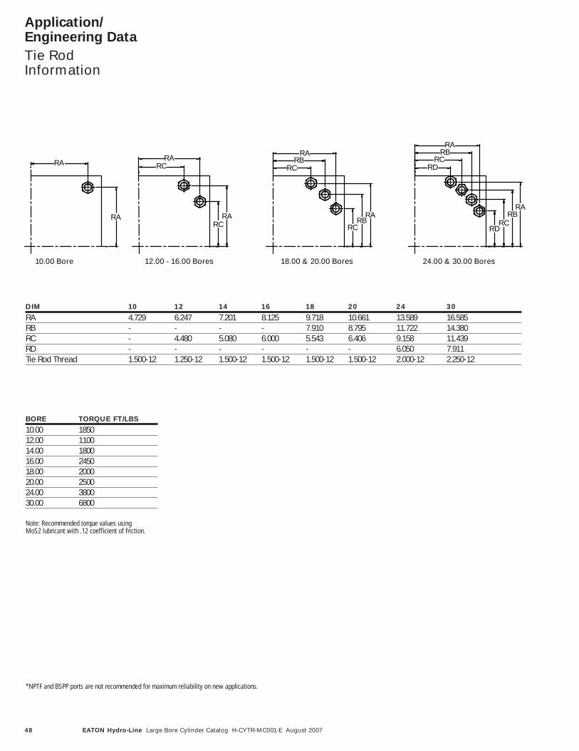
*NPTF and BSPP ports are not recommended for maximum reliability on new applications.
Note: Recommended torque values using MoS2 lubricant with .12 coefficient of friction.
DIM 10 12 14 16 18 20 24 30
RA 4.729 6.247 7.201 8.125 9.718 10.661 13.589 16.585RB - - - - 7.910 8.795 11.722 14.380RC - 4.480 5.080 6.000 5.543 6.406 9.158 11.439RD - - - - - - 6.050 7.911Tie Rod Thread 1.500-12 1.250-12 1.500-12 1.500-12 1.500-12 1.500-12 2.000-12 2.250-12
Application/Engineering Data
Tie RodInformation
RCRB
RA
RCRB
RARA
RA
RC
RC
12.00 - 16.00 Bores 18.00 & 20.00 Bores 24.00 & 30.00 Bores
RB
RCRB
RDRC
RD
RA
RARA
RA
10.00 Bore
BORE TORQUE FT/LBS
10.00 185012.00 110014.00 180016.00 245018.00 200020.00 250024.00 380030.00 6800

49EATON Hydro-Line Large Bore Cylinder Catalog H-CYTR-MC001-E August 2007
LL L
L L
Application/Engineering Data
Buckling Chart
MAXIMUM LENGTH L (IN) AT WORKING PRESSURE (PSI) - Length L in full extend condition
Rigid Mount Styles 01, 09, 14 Swivel Mount Styles 10, 15BORE ROD
ø ø 3000 2000 1500 1000 750 500 250 3000 2000 1500 1000 750 500 250in in psi psi psi psi psi psi psi psi psi psi psi psi psi psi10.00 4.50 120 147 170 208 240 294 416 85 104 120 147 170 208 294
5.00 131 182 210 257 297 364 514 92 129 148 182 210 257 3645.50 180 220 254 311 359 440 622 127 156 180 220 254 311 4407.00 291 356 411 504 582 713 1008 206 252 291 356 411 504 713
12.00 5.50 141 183 212 259 299 367 518 100 130 150 183 212 259 3677.00 225 297 343 420 485 594 840 159 210 242 297 343 420 5948.00 316 388 448 548 633 776 1097 224 274 317 388 448 548 776
14.00 7.00 104 247 294 360 416 509 720 73 174 208 254 294 360 5098.00 245 332 384 470 543 665 940 173 235 271 332 384 470 6659.00 341 421 486 595 687 841 1190 241 297 344 421 486 595 84110.00 424 519 600 735 848 1039 1469 300 367 424 519 600 735 1039
16.00 8.00 118 282 336 411 475 582 823 84 199 237 291 336 411 5829.00 265 368 425 521 601 736 1041 187 260 301 368 425 521 73610.00 364 454 525 643 742 909 1285 257 321 371 454 525 643 909
18.00 9.00 133 317 378 463 534 654 925 94 224 267 327 378 463 65410.00 283 404 466 571 660 808 1143 200 286 330 404 466 571 808
20.00 10.00 148 353 420 514 594 727 1028 105 249 297 364 420 514 72724.00 11.00 138 321 421 518 599 733 1037 98 227 297 367 423 518 73330.00 14.00 229 429 547 672 776 950 1344 162 304 387 475 549 672 950
End conditions for above chart:Mount Condition01,09,14 Fixed-Guided10,15 Pin-Pin
15 14 10 09 01
Buckling Chart
Maximum allowable length’L’ in full extend condition.
In push applications, a cylinderacts as a loaded column. Touse the table below, first goto the section for yourmounting style. Then locatethe column with pressurewhich is closest to, but notbelow, your application’soperating pressure. The inter-section of operating pressure
and the bore / rod size repre-sents the maximum allowablelength ‘L’ in full extend condition.This maximum length isbased on column loadinganalysis only and does notconsider side loading, stoptube requirements, or othercylinder stroke limiter.
For pressures above 3000psi, consult your local EatonHydro-Line representative.
2
2
FL
EICP
π=
−=224
2
1EkC
LSF
ASP
yy
π ≤yS
ECkL 22 π
yS
EC
k
L 22 π
Formulas
Calculation according to Euler
Calculation according to Jb Johnson
F Safety factor, 3.5 up to 10.00 inch rod. 3.00 for 11.00 and 14.00
P Critical load, LbE Modulus of elasticity, 30,000,000 psiL Length, inI Moment of inertia, in^4C End condition
Fixed-Guided 2Fixed-Fixed 4Pin-Pin 1
A Rod area, in²k Radius of gyration, in

© 2007 Eaton CorporationAll Rights Reserved Printed in USADocument No. H-CYTR-MC001-EAugust 2007
EatonHydraulics Operations USA14615 Lone Oak RoadEden Prairie, MN 55344USATel: 952-937-9800Fax: 952-294-7722www.hydraulics.eaton.com
EatonHydraulics Operations EuropeRoute de la Longeraie 71110 MorgesSwitzerlandTel: +41 (0) 21 811 4600Fax: +41 (0) 21 811 4601
EatonHydraulics Operations Asia Pacific 11th Floor Hong Kong New World Tower 300 Huaihai Zhong Road Shanghai 200021 China Tel: 86-21-6387-9988 Fax: 86-21-6335-3912