hydraulic maintenance & safety - miningquiz.comminingquiz.com/pdf/hydraulic_safety/gates... ·...
TRANSCRIPT
HYDRAULIC MAINTENANCE & SAFETY
TIPS TO PREVENT DOWNTIME AND SAVE YOU MONEY
TM
2
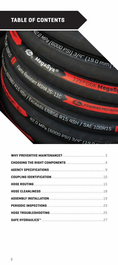
WHY PREVENTIVE MAINTENANCE? .......................................................3
CHOOSING THE RIGHT COMPONENTS ..................................................4
AGENCY SPECIFICATIONS ........................................................................9
COUPLING IDENTIFICATION ...................................................................10
HOSE ROUTING .........................................................................................15
HOSE CLEANLINESS ................................................................................18
ASSEMBLY INSTALLATION ......................................................................19
PERIODIC INSPECTIONS .........................................................................23
HOSE TROUBLESHOOTING .....................................................................25
SAFE HYDRAULICS™ ................................................................................27
TABLE OF CONTENTS
3
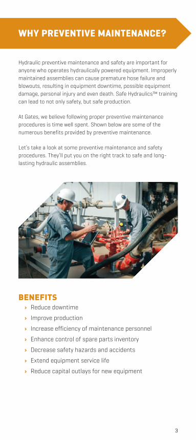
WHY PREVENTIVE MAINTENANCE?
BENEFITS› Reduce downtime
› Improve production
› Increase efficiency of maintenance personnel
› Enhance control of spare parts inventory
› Decrease safety hazards and accidents
› Extend equipment service life
› Reduce capital outlays for new equipment
Hydraulic preventive maintenance and safety are important for anyone who operates hydraulically powered equipment. Improperly maintained assemblies can cause premature hose failure and blowouts, resulting in equipment downtime, possible equipment damage, personal injury and even death. Safe Hydraulics™ training can lead to not only safety, but safe production.
At Gates, we believe following proper preventive maintenance procedures is time well spent. Shown below are some of the numerous benefits provided by preventive maintenance.
Let’s take a look at some preventive maintenance and safety procedures. They’ll put you on the right track to safe and long-lasting hydraulic assemblies.
4
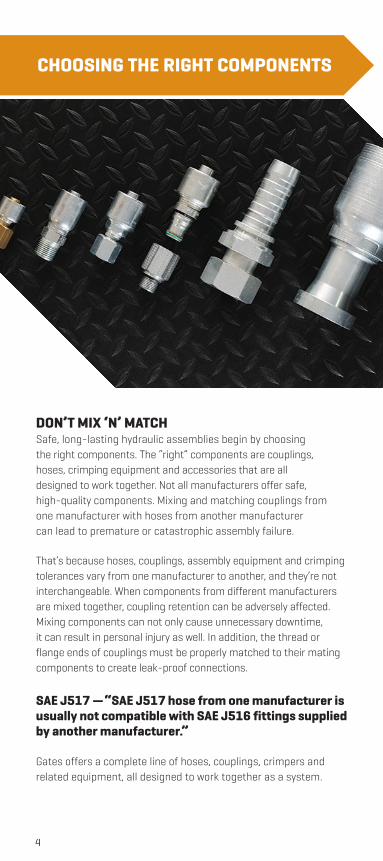
CHOOSING THE RIGHT COMPONENTS
DON’T MIX ‘N’ MATCHSafe, long-lasting hydraulic assemblies begin by choosing the right components. The “right” components are couplings, hoses, crimping equipment and accessories that are all designed to work together. Not all manufacturers offer safe, high-quality components. Mixing and matching couplings from one manufacturer with hoses from another manufacturer can lead to premature or catastrophic assembly failure.
That’s because hoses, couplings, assembly equipment and crimping tolerances vary from one manufacturer to another, and they’re not interchangeable. When components from different manufacturers are mixed together, coupling retention can be adversely affected. Mixing components can not only cause unnecessary downtime, it can result in personal injury as well. In addition, the thread or flange ends of couplings must be properly matched to their mating components to create leak-proof connections.
SAE J517 — “SAE J517 hose from one manufacturer is usually not compatible with SAE J516 fittings supplied by another manufacturer.”
Gates offers a complete line of hoses, couplings, crimpers and related equipment, all designed to work together as a system.
5
Gates components meet stringent test requirements and are engineered to provide the highest-quality, longest-lasting, safest assemblies available. Your Gates distributor is specially trained to make sure you get the hose assemblies that best meet your needs.
THE CRITICAL DESIGN FACTORHydraulic system performance is determined by the weakest component, which can be the hose/coupling interface, reassuring that Gates assembly procedures are crucial. Controlling how the coupling is connected to the hose and their interaction is critical to designing effective, reliable and safe hydraulic hose assemblies.
CHOOSING THE RIGHT HOSEChoosing the right hose is the first step to long and safe assembly service life. But before we look into how to select the proper hose for the job, let’s first take a look at the benefits of using rubber hose in fluid power applications. Unlike rigid tubing, rubber hose offers several advantages:
› Less susceptible to vibration and movement.
› Requires no brazing or specialized bending.
› Easier to obtain in the aftermarket.
› Faster to route around obstacles.
› Absorbs sound and impulses.
› Dampens pressure surges.
Given its superior availability and routing advantages, rubber hose is preferred over metal tubing by most maintenance personnel. In fact, it’s not uncommon for maintenance technicians to replace metal tubing with a hose assembly.
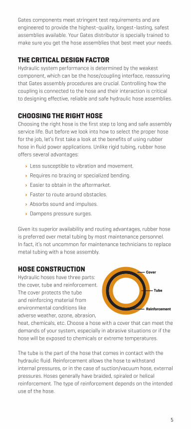
HOSE CONSTRUCTION Hydraulic hoses have three parts: the cover, tube and reinforcement. The cover protects the tube and reinforcing material from environmental conditions like adverse weather, ozone, abrasion, heat, chemicals, etc. Choose a hose with a cover that can meet the demands of your system, especially in abrasive situations or if the hose will be exposed to chemicals or extreme temperatures.
The tube is the part of the hose that comes in contact with the hydraulic fluid. Reinforcement allows the hose to withstand internal pressures, or in the case of suction/vacuum hose, external pressures. Hoses generally have braided, spiraled or helical reinforcement. The type of reinforcement depends on the intended use of the hose.
Cover
Reinforcement
Tube
6
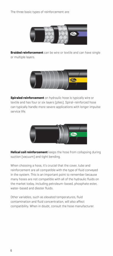
The three basic types of reinforcement are:
Braided reinforcement can be wire or textile and can have single or multiple layers.
Spiraled reinforcement on hydraulic hose is typically wire or textile and has four or six layers (plies). Spiral-reinforced hose can typically handle more severe applications with longer impulse service life.
Helical coil reinforcement keeps the hose from collapsing during suction (vacuum) and tight bending.
When choosing a hose, it’s crucial that the cover, tube and reinforcement are all compatible with the type of fluid conveyed in the system. This is an important point to remember because many hoses are not compatible with all of the hydraulic fluids on the market today, including petroleum-based, phosphate ester, water-based and diester fluids.
Other variables, such as elevated temperatures, fluid contamination and fluid concentration, will also affect compatibility. When in doubt, consult the hose manufacturer.
7
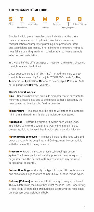
THE “STAMPED” METHOD
Size
Temperature
Application
Material
Pressure Delivery (Volume)
Ends/Couplings
S T A M P E D
Studies by fluid power manufacturers indicate that the three most common causes of hydraulic hose failure are abuse, misapplication and improper plumbing. Equipment operators and technicians can reduce, if not eliminate, premature hydraulic hose failure by giving maximum consideration to hose assembly selection and installation.
Yet, with all of the different types of hoses on the market, choosing the right one can be difficult.
Gates suggests using the “STAMPED” method to ensure you get the right hose assembly for the job. “STAMPED” stands for Size, Temperature, Application, Material to be conveyed, Pressure, Ends or Couplings, and Delivery (Volume).
Here’s how it works:Size — Choose a hose with an inside diameter that is adequate to minimize pressure loss and to avoid hose damage caused by the heat generated by excessive fluid turbulence.
Temperature — The hose must be able to withstand the system’s minimum and maximum fluid and ambient temperatures.
Application — Determine where or how the hose will be used. You’ll need to know the equipment type, working and impulse pressures, fluid to be used, bend radius, static conductivity, etc.
Material to be conveyed — The hose, including the hose tube and cover, along with the couplings and O-rings, must be compatible with the type of fluid being conveyed.
Pressure — Know the system pressure, including pressure spikes. The hose’s published working pressure must be equal to, or greater than, the normal system pressure and any pressure surges it will encounter.
Ends or Couplings — Identify the type of threads the system uses and select couplings that are compatible with those thread types.
Delivery (Volume) — How much fluid must go through the hose? This will determine the size of hose that must be used. Undersizing a hose leads to increased pressure loss. Oversizing the hose adds unnecessary cost, weight and bulk.
8
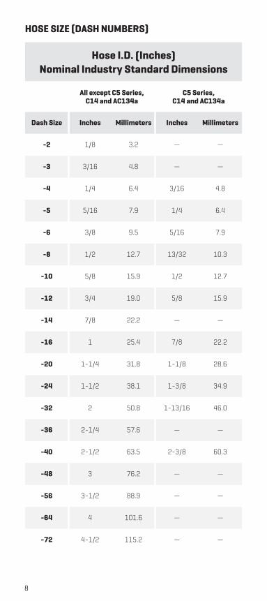
HOSE SIZE (DASH NUMBERS)
Hose I.D. (Inches)Nominal Industry Standard Dimensions
All except C5 Series, C14 and AC134a
C5 Series, C14 and AC134a
Dash Size Inches Millimeters Inches Millimeters
-2 1/8 3.2 — —
-3 3/16 4.8 — —
-4 1/4 6.4 3/16 4.8
-5 5/16 7.9 1/4 6.4
-6 3/8 9.5 5/16 7.9
-8 1/2 12.7 13/32 10.3
-10 5/8 15.9 1/2 12.7
-12 3/4 19.0 5/8 15.9
-14 7/8 22.2 — —
-16 1 25.4 7/8 22.2
-20 1-1/4 31.8 1-1/8 28.6
-24 1-1/2 38.1 1-3/8 34.9
-32 2 50.8 1-13/16 46.0
-36 2-1/4 57.6 — —
-40 2-1/2 63.5 2-3/8 60.3
-48 3 76.2 — —
-56 3-1/2 88.9 — —
-64 4 101.6 — —
-72 4-1/2 115.2 — —

9
AGENCY SPECIFICATIONS
INDUSTRY AGENCIESABS — American Bureau of Shipping
AS — Australia Standard
DIN — Deutsche Industrial Norme, German
DNV — Det Norske Veritas for North Sea Floating Vessels
EN — European Norm/Standard
GL — Germanischer Lloyd
IJS — Industrial Jack Specifications
RCCC — Regular Common Carrier Conference for Fleet Truck and Bus
SAE — Society of Automotive Engineers
GOVERNMENT AGENCIESDOT/FMVSS — U.S. Department of Transportation/
Federal Motor Vehicle Safety Standards
MSHA — U.S. Mine Safety and Health Administration
USCG — U.S. Coast Guard
10
COUPLING IDENTIFICATION
Identifying couplings is as easy as 1-2-3.1. Determine seat type:
› Thread interface
› O-ring
› Mated angle or mechanical joint
› Mated angle with O-ring
2. Visually identify
3. Measure threads
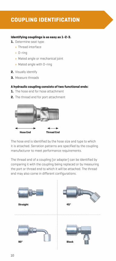
A hydraulic coupling consists of two functional ends:1. The hose end for hose attachment
2. The thread end for port attachment
Hose End Thread End
The hose end is identified by the hose size and type to which it is attached. Serration patterns are specified by the coupling manufacturer to meet performance requirements.
The thread end of a coupling (or adapter) can be identified by comparing it with the coupling being replaced or by measuring the port or thread end to which it will be attached. The thread end may also come in different configurations.
Straight
90°
45°
Block
11
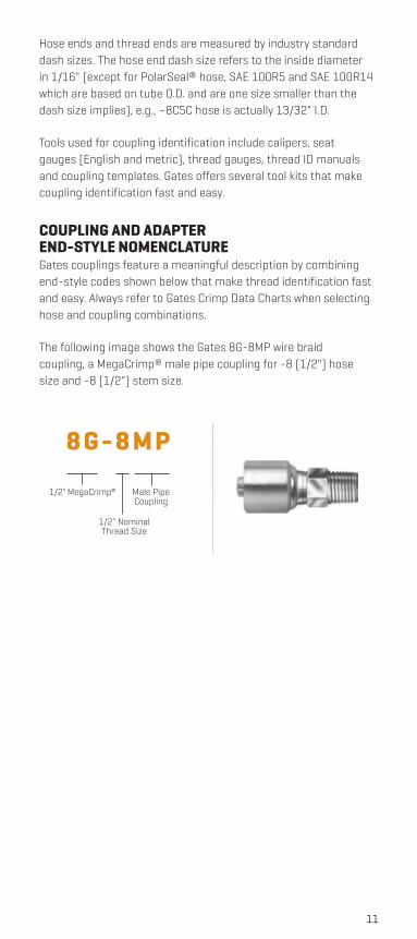
1/2" MegaCrimp®
1/2" Nominal Thread Size
Male Pipe Coupling
8 G - 8 M P
Hose ends and thread ends are measured by industry standard dash sizes. The hose end dash size refers to the inside diameter in 1/16" (except for PolarSeal® hose, SAE 100R5 and SAE 100R14 which are based on tube O.D. and are one size smaller than the dash size implies), e.g., –8C5C hose is actually 13/32" I.D.
Tools used for coupling identification include calipers, seat gauges (English and metric), thread gauges, thread ID manuals and coupling templates. Gates offers several tool kits that make coupling identification fast and easy.
COUPLING AND ADAPTER END-STYLE NOMENCLATUREGates couplings feature a meaningful description by combining end-style codes shown below that make thread identification fast and easy. Always refer to Gates Crimp Data Charts when selecting hose and coupling combinations.
The following image shows the Gates 8G-8MP wire braid coupling, a MegaCrimp® male pipe coupling for -8 (1/2") hose size and -8 (1/2") stem size.
12
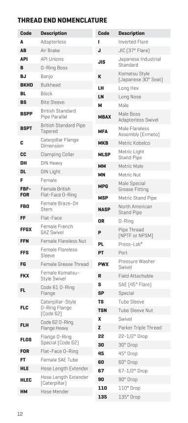
Code Description
A Adapterless
AB Air Brake
API API Unions
B O-Ring Boss
BJ Banjo
BKHD Bulkhead
BL Block
BS Bite Sleeve
BSPP British Standard Pipe Parallel
BSPT British Standard Pipe Tapered
C Caterpillar Flange Dimension
CC Clamping Collar
DH DIN Heavy
DL DIN Light
F Female
FBF-FOR
Female British Flat-Face O-Ring
FBO Female Braze-On Stem
FF Flat-Face
FFGX Female French GAZ Swivel
FFN Female Flareless Nut
FFS Female Flareless Sleeve
FG Female Grease Thread
FKX Female Komatsu- Style Swivel
FL Code 61 O-Ring Flange
FLCCaterpillar-Style O-Ring Flange (Code 62)
FLH Code 62 O-Ring Flange Heavy
FLOS Flange O-Ring Special (Code 62)
FOR Flat-Face O-Ring
FT Female SAE Tube
HLE Hose Length Extender
HLEC Hose Length Extender (Caterpillar)
HM Hose Mender
Code Description
I Inverted Flare
J JIC (37° Flare)
JIS Japanese Industrial Standard
K Komatsu Style (Japanese 30° Seat)
LH Long Hex
LN Long Nose
M Male
MBAX Male Boss Adapterless Swivel
MFA Male Flareless Assembly (Ermeto)
MKB Metric Kobelco
MLSP Metric Light Stand Pipe
MM Metric Male
MN Metric Nut
MPG Male Special Grease Fitting
MSP Metric Stand Pipe
NASP North American Stand Pipe
OR O-Ring
P Pipe Thread (NPTF or NPSM)
PL Press-Lok®
PT Port
PWX Pressure Washer Swivel
R Field Attachable
S SAE (45° Flare)
SP Special
TS Tube Sleeve
TSN Tube Sleeve Nut
X Swivel
Z Parker Triple Thread
22 22-1/2° Drop
30 30° Drop
45 45° Drop
60 60° Drop
67 67-1/2° Drop
90 90° Drop
110 110° Drop
135 135° Drop
THREAD END NOMENCLATURE
13
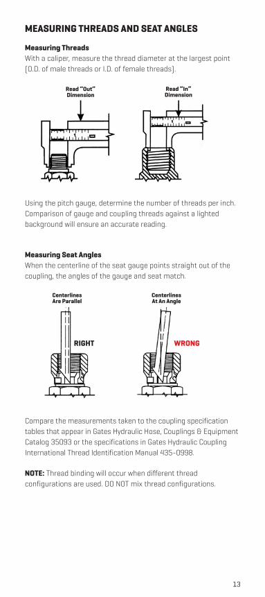
MEASURING THREADS AND SEAT ANGLES
Measuring ThreadsWith a caliper, measure the thread diameter at the largest point (O.D. of male threads or I.D. of female threads).
Read “Out” Dimension
Read “In” Dimension
Using the pitch gauge, determine the number of threads per inch. Comparison of gauge and coupling threads against a lighted background will ensure an accurate reading.
Measuring Seat Angles When the centerline of the seat gauge points straight out of the coupling, the angles of the gauge and seat match.
CenterlinesAre Parallel
CenterlinesAt An Angle
WRONGRIGHT
Compare the measurements taken to the coupling specification tables that appear in Gates Hydraulic Hose, Couplings & Equipment Catalog 35093 or the specifications in Gates Hydraulic Coupling International Thread Identification Manual 435-0998.
NOTE: Thread binding will occur when different thread configurations are used. DO NOT mix thread configurations.
14
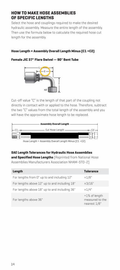
HOW TO MAKE HOSE ASSEMBLIES OF SPECIFIC LENGTHSSelect the hose and couplings required to make the desired hydraulic assembly. Measure the entire length of the assembly. Then use the formula below to calculate the required hose cut length for the assembly.
Hose Length = Assembly Overall Length Minus (C1 +C2)
Female JIC 37° Flare Swivel — 90° Bent Tube
LC
H2
T
Cut-off value “C” is the length of that part of the coupling not directly in contact with or applied to the hose. Therefore, subtract the two “C” values from the total length of the assembly and you will have the approximate hose length to be replaced.
Assembly Overall Length
Cut Hose Length
Hose Length = Assembly Overall Length Minus (C1 +C2)
C1 C2
SAE Length Tolerances for Hydraulic Hose Assemblies and Specified Hose Lengths (Reprinted from National Hose Assemblies Manufacturers Association NHAM-STD-2)
Length Tolerance
For lengths from 0" up to and including 12" ±1/8"
For lengths above 12" up to and including 18" ±3/16"
For lengths above 18" up to and including 36" ±1/4"
For lengths above 36" +1% of length measured to the nearest 1/8"
15
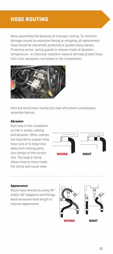
HOSE ROUTING
Here are some hose routing tips that will prevent unnecessary assembly failures:
AbrasionRun hose in the installation so that it avoids rubbing and abrasion. Often, clamps are required to support long hose runs or to keep hose away from moving parts. Use clamps of the correct size. Too large a clamp allows hose to move inside the clamp and cause wear.
AppearanceRoute hose directly by using 45° and/or 90° adapters and fittings. Avoid excessive hose length to improve appearance.
Many assemblies fail because of improper routing. To minimize damage caused by excessive flexing or whipping, all replacement hose should be restrained, protected or guided using clamps. Protective armor, spring guards or sleeves made of abrasion-, temperature- or chemical-resistant material will help protect hose from cuts, abrasions, corrosives or hot components.
WRONG RIGHT
WRONG RIGHT
16
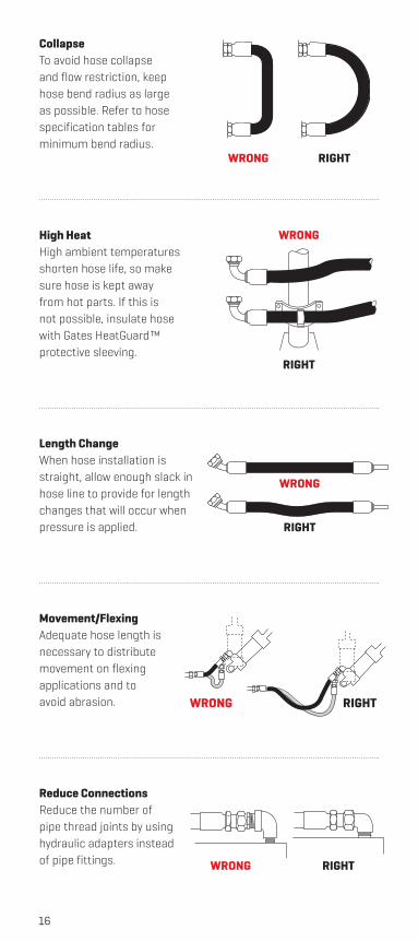
CollapseTo avoid hose collapse and flow restriction, keep hose bend radius as large as possible. Refer to hose specification tables for minimum bend radius.
High HeatHigh ambient temperatures shorten hose life, so make sure hose is kept away from hot parts. If this is not possible, insulate hose with Gates HeatGuard™ protective sleeving.
Length ChangeWhen hose installation is straight, allow enough slack in hose line to provide for length changes that will occur when pressure is applied.
Movement/FlexingAdequate hose length is necessary to distribute movement on flexing applications and to avoid abrasion.
Reduce ConnectionsReduce the number of pipe thread joints by using hydraulic adapters instead of pipe fittings.
WRONG RIGHT
WRONG RIGHT
WRONG
RIGHT
WRONG
RIGHT
RIGHTWRONG
17
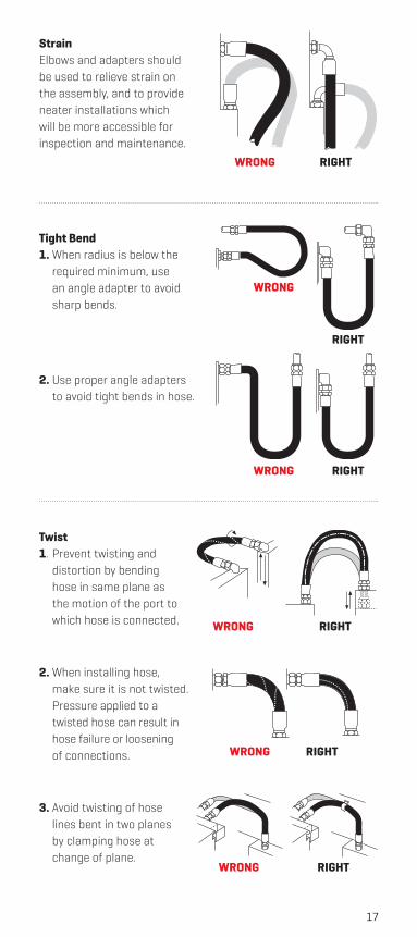
StrainElbows and adapters should be used to relieve strain on the assembly, and to provide neater installations which will be more accessible for inspection and maintenance.
Tight Bend1. When radius is below the
required minimum, use an angle adapter to avoid sharp bends.
2. Use proper angle adapters to avoid tight bends in hose.
Twist1. Prevent twisting and
distortion by bending hose in same plane as the motion of the port to which hose is connected.
2. When installing hose, make sure it is not twisted. Pressure applied to a twisted hose can result in hose failure or loosening of connections.
3. Avoid twisting of hose lines bent in two planes by clamping hose at change of plane.
WRONG RIGHT
WRONG RIGHT
WRONG
RIGHT
WRONG RIGHT
WRONG RIGHT
WRONG RIGHT
18
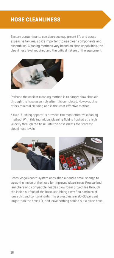
System contaminants can decrease equipment life and cause expensive failures, so it’s important to use clean components and assemblies. Cleaning methods vary based on shop capabilities, the cleanliness level required and the critical nature of the equipment.
Perhaps the easiest cleaning method is to simply blow shop air through the hose assembly after it is completed. However, this offers minimal cleaning and is the least effective method.
A fluid-flushing apparatus provides the most effective cleaning method. With this technique, cleaning fluid is flushed at a high velocity through the hose until the hose meets the strictest cleanliness levels.
Gates MegaClean™ system uses shop air and a small sponge to scrub the inside of the hose for improved cleanliness. Pressurized launchers and compatible nozzles blow foam projectiles through the inside surface of the hose, scrubbing away fine particles of loose dirt and contaminants. The projectiles are 20–30 percent larger than the hose I.D., and leave nothing behind but a clean hose.
HOSE CLEANLINESS
19
ASSEMBLY INSTALLATION
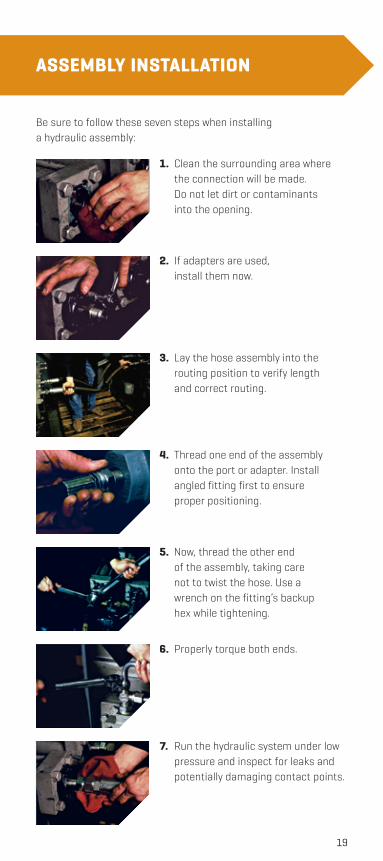
Be sure to follow these seven steps when installing a hydraulic assembly:
7. Run the hydraulic system under low pressure and inspect for leaks and potentially damaging contact points.
1. Clean the surrounding area where the connection will be made. Do not let dirt or contaminants into the opening.
2. If adapters are used, install them now.
3. Lay the hose assembly into the routing position to verify length and correct routing.
4. Thread one end of the assembly onto the port or adapter. Install angled fitting first to ensure proper positioning.
5. Now, thread the other end of the assembly, taking care not to twist the hose. Use a wrench on the fitting’s backup hex while tightening.
6. Properly torque both ends.
20
INSTALLATION TORQUEInstallation torque is important to ensure a proper leak-free seal. Over-torquing of a threaded connection can stretch and damage threads and seat angles. It can also damage the staking area of a nut or possibly break a bolt on the port area. Under-torquing does not allow proper sealing. Torque should always be checked to ensure tightening is within accepted limits. The most reliable method of torquing threaded connections is to first hand-tighten the connection, then use a torque wrench to measure the torque. Torque values vary by thread configuration as follows:
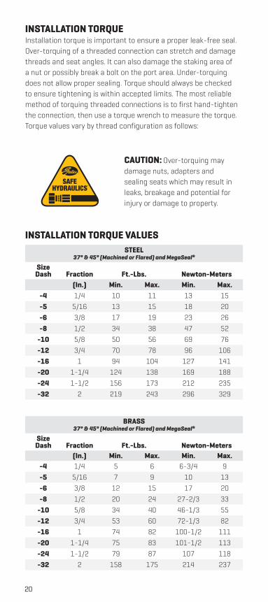
CAUTION: Over-torquing may damage nuts, adapters and sealing seats which may result in leaks, breakage and potential for injury or damage to property.
INSTALLATION TORQUE VALUES
BRASS37° & 45° (Machined or Flared) and MegaSeal®
Size Dash Fraction Ft.-Lbs. Newton-Meters
(In.) Min. Max. Min. Max.-4 1/4 5 6 6-3/4 9-5 5/16 7 9 10 13-6 3/8 12 15 17 20-8 1/2 20 24 27-2/3 33
-10 5/8 34 40 46-1/3 55-12 3/4 53 60 72-1/3 82-16 1 74 82 100-1/2 111-20 1-1/4 75 83 101-1/2 113-24 1-1/2 79 87 107 118-32 2 158 175 214 237
STEEL37° & 45° (Machined or Flared) and MegaSeal®
Size Dash Fraction Ft.-Lbs. Newton-Meters
(In.) Min. Max. Min. Max.-4 1/4 10 11 13 15-5 5/16 13 15 18 20-6 3/8 17 19 23 26-8 1/2 34 38 47 52
-10 5/8 50 56 69 76-12 3/4 70 78 96 106-16 1 94 104 127 141-20 1-1/4 124 138 169 188-24 1-1/2 156 173 212 235-32 2 219 243 296 329
TM
21
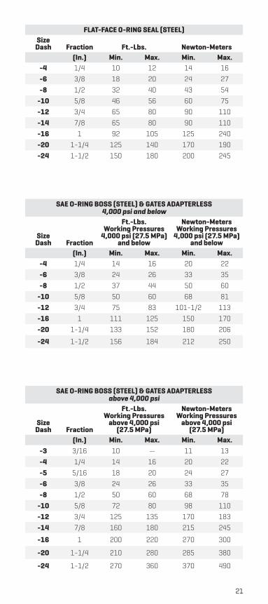
FLAT-FACE O-RING SEAL (STEEL)Size
Dash Fraction Ft.-Lbs. Newton-Meters(In.) Min. Max. Min. Max.
-4 1/4 10 12 14 16-6 3/8 18 20 24 27-8 1/2 32 40 43 54
-10 5/8 46 56 60 75-12 3/4 65 80 90 110-14 7/8 65 80 90 110-16 1 92 105 125 240-20 1-1/4 125 140 170 190-24 1-1/2 150 180 200 245
SAE O-RING BOSS (STEEL) & GATES ADAPTERLESS4,000 psi and below
Size Dash Fraction
Ft.-Lbs. Working Pressures
4,000 psi (27.5 MPa) and below
Newton-Meters Working Pressures
4,000 psi (27.5 MPa) and below
(In.) Min. Max. Min. Max.-4 1/4 14 16 20 22-6 3/8 24 26 33 35-8 1/2 37 44 50 60
-10 5/8 50 60 68 81-12 3/4 75 83 101-1/2 113-16 1 111 125 150 170-20 1-1/4 133 152 180 206
-24 1-1/2 156 184 212 250
SAE O-RING BOSS (STEEL) & GATES ADAPTERLESSabove 4,000 psi
Size Dash Fraction
Ft.-Lbs. Working Pressures
above 4,000 psi (27.5 MPa)
Newton-Meters Working Pressures
above 4,000 psi (27.5 MPa)
(In.) Min. Max. Min. Max.-3 3/16 10 — 11 13-4 1/4 14 16 20 22-5 5/16 18 20 24 27-6 3/8 24 26 33 35-8 1/2 50 60 68 78
-10 5/8 72 80 98 110-12 3/4 125 135 170 183-14 7/8 160 180 215 245
-16 1 200 220 270 300
-20 1-1/4 210 280 285 380
-24 1-1/2 270 360 370 490
22
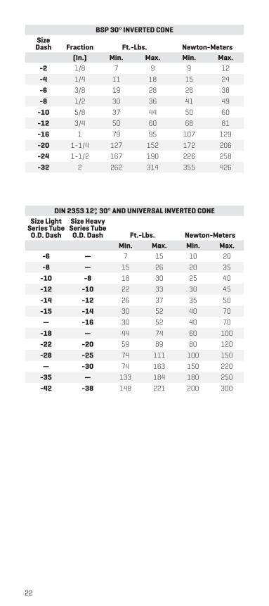
BSP 30° INVERTED CONESize
Dash Fraction Ft.-Lbs. Newton-Meters(In.) Min. Max. Min. Max.
-2 1/8 7 9 9 12-4 1/4 11 18 15 24-6 3/8 19 28 26 38-8 1/2 30 36 41 49
-10 5/8 37 44 50 60-12 3/4 50 60 68 81-16 1 79 95 107 129-20 1-1/4 127 152 172 206-24 1-1/2 167 190 226 258-32 2 262 314 355 426
DIN 2353 12°, 30° AND UNIVERSAL INVERTED CONESize Light
Series Tube O.D. Dash
Size Heavy Series Tube
O.D. Dash Ft.-Lbs. Newton-MetersMin. Max. Min. Max.
-6 — 7 15 10 20-8 — 15 26 20 35
-10 -8 18 30 25 40-12 -10 22 33 30 45-14 -12 26 37 35 50-15 -14 30 52 40 70
— -16 30 52 40 70-18 — 44 74 60 100-22 -20 59 89 80 120-28 -25 74 111 100 150
— -30 74 163 150 220-35 — 133 184 180 250-42 -38 148 221 200 300
23
PERIODIC INSPECTIONS
Periodic hose assembly inspections can prevent unwanted and unexpected assembly failures. During normal operations, be aware of how the equipment sounds, feels, etc. Be sure to check any noticeable abnormalities.
Hose inspection can vary by equipment type. Refer to your equipment manual and always follow the manufacturer’s inspection recommendations. If the recommendations are not available, use the following guidelines:
› Inspect mobile equipment every 400 to 600 hours or every three months, whichever comes first.
› Inspect stationary equipment every three months.
Other factors that influence inspections include:
› Whether the equipment is critical to the operation.
› Operating pressures and temperatures.
› Difficult routing conditions.
› Extreme environmental factors.
› Accessibility of equipment.
24
INSPECTION PROCEDURESHere’s a checklist to help keep your equipment running strong:
1. First, turn off and lock out the equipment’s power.
2. Place the equipment and components in a safe and/or neutral position.
3. Remove access panels and inspect hose and fittings for damage or leaks.
4. Repair or replace assemblies as needed.
5. Inspect other hydraulic components.
6. Reinstall access panels.
7. Turn power back on.
8. Pay attention to unusual noises, vibrations, etc.
The Mine Safety and Health Administration (MSHA) recommends following the SLAM Risks program, intended for use as introductory material for risk assessment training across all industries.
SLAM RISKS THE SMART WAY!CONTRACTORS:Stop — Think through the task.
Look — Identify the hazards for each job step.
Analyze — Determine if you have the proper knowledge, training and tools.
Manage — Remove or control hazards and use proper equipment.
OPERATORS:Stop — Isolate each step in a task and identify past and potential accidents, injuries and violations.
Measure — Evaluate the risks associated with the task and barriers that have allowed hazards to cause injuries.
Act — Implement controls to minimize or eliminate any hazards that make the risk unacceptable.
Review — Conduct frequent work site visits to observe practices and audit accidents, injuries and violations to identify root causes.
Train — Develop a human factor-based action plan and involve and train the miners.
www.msha.gov
25
HOSE TROUBLESHOOTING
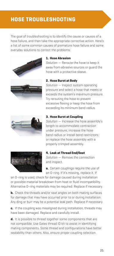
The goal of troubleshooting is to identify the cause or causes of a hose failure, and then take the appropriate corrective action. Here’s a list of some common causes of premature hose failure and some everyday solutions to correct the problems:
1. Hose AbrasionSolution — Reroute the hose to keep it away from abrasive sources or guard the hose with a protective sleeve.
2. Hose Burst at BodySolution — Inspect system operating pressure and select a hose that meets or exceeds the system’s maximum pressure. Try rerouting the hose to prevent excessive flexing or keep the hose from exceeding its minimum bend radius.
3. Hose Burst at CouplingSolution — Increase the hose assembly’s length to accommodate contraction under pressure; increase the hose bend radius or install bend restrictors; or replace the hose assembly with a properly crimped assembly.
4. Leak at Thread End/SeatSolution — Remove the connection and inspect.
a. Certain couplings require the use of an O-ring. If it’s missing, replace it. If
an O-ring is used, check for damage caused during installation or possible material breakdown from heat or fluid incompatibility. Alternative O-ring materials may be required. Replace if necessary.
b. Check the threads and/or seat angles on both mating surfaces for damage that may have occurred prior to or during installation. Any ding or burr may be a potential leak path. Replace if necessary.
c. If the coupling was misaligned during installation, threads may have been damaged. Replace and carefully install.
d. It is possible to thread together some components that are not compatible. Use Gates thread ID kit to assist in identifying mating components. Some thread end configurations have better sealability than others. Also, ensure proper coupling selection.
26
e. Over-torquing of a threaded connection can damage threads and mating seat angles. Over-torquing can also damage the staking area of the nut, causing cracking of either the nut or seat. Under-torquing does not allow proper sealing. Use of a torque wrench can alleviate such problems.
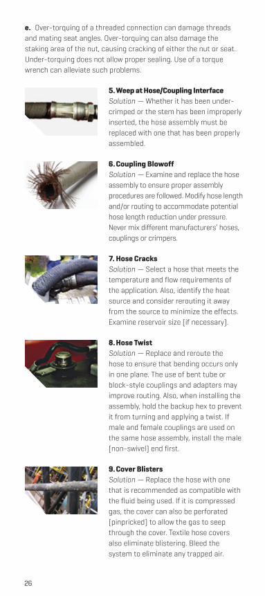
5. Weep at Hose/Coupling InterfaceSolution — Whether it has been under-crimped or the stem has been improperly inserted, the hose assembly must be replaced with one that has been properly assembled.
6. Coupling BlowoffSolution — Examine and replace the hose assembly to ensure proper assembly procedures are followed. Modify hose length and/or routing to accommodate potential hose length reduction under pressure. Never mix different manufacturers’ hoses, couplings or crimpers.
7. Hose CracksSolution — Select a hose that meets the temperature and flow requirements of the application. Also, identify the heat source and consider rerouting it away from the source to minimize the effects. Examine reservoir size (if necessary).
8. Hose TwistSolution — Replace and reroute the hose to ensure that bending occurs only in one plane. The use of bent tube or block-style couplings and adapters may improve routing. Also, when installing the assembly, hold the backup hex to prevent it from turning and applying a twist. If male and female couplings are used on the same hose assembly, install the male (non-swivel) end first.
9. Cover BlistersSolution — Replace the hose with one that is recommended as compatible with the fluid being used. If it is compressed gas, the cover can also be perforated (pinpricked) to allow the gas to seep through the cover. Textile hose covers also eliminate blistering. Bleed the system to eliminate any trapped air.
27
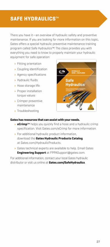
SAFE HYDRAULICS™
There you have it—an overview of hydraulic safety and preventive maintenance. If you are looking for more information on this topic, Gates offers a special hydraulic preventive maintenance training program called Safe Hydraulics™. The class provides you with everything you need to know to properly maintain your hydraulic equipment for safe operation:
› Fitting orientation
› Coupling identification
› Agency specifications
› Hydraulic fluids
› Hose storage life
› Proper installation torque values
› Crimper preventive maintenance
› Troubleshooting
Gates has resources that can assist with your needs. › eCrimp™ helps you quickly find a hose and a hydraulic crimp specification. Visit Gates.com/eCrimp for more information.
› For additional hydraulic product information, download the Gates Hydraulic Products Catalog at Gates.com/HydraulicProducts.
› Gates technical experts are available to help. Email Gates Engineering Support at [email protected].
For additional information, contact your local Gates hydraulic distributor or visit us online at Gates.com/SafeHydraulics.
Safety, preventive maintenance, troubleshooting, coupling identification + selection, assembly, and installation.
Safe Hydraulics™
TM
HYDRAULIC HOSE + COUPLINGS

GATES CORPORATION
Gates.com/SafeHydraulics
©2015 Gates Corporation 39595-P 05/2015
THE WORLD’S MOST TRUSTED NAME IN BELTS, HOSE AND HYDRAULICS