hydraulic principles of centrifugal pumps
TRANSCRIPT

Technische Universität BerlinDepartment of Fluid System Dynamics
Prof. Dr.-Ing. P.U. Thamsen
Technical University Berlin
Hydraulic Principles of
Centrifugal Pumps
Technische Universität BerlinDepartment of Fluid System Dynamics
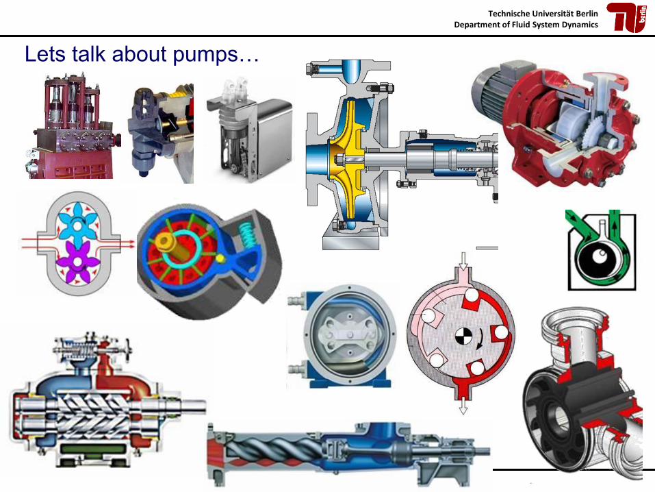
Lets talk about pumps…
Technische Universität BerlinDepartment of Fluid System Dynamics
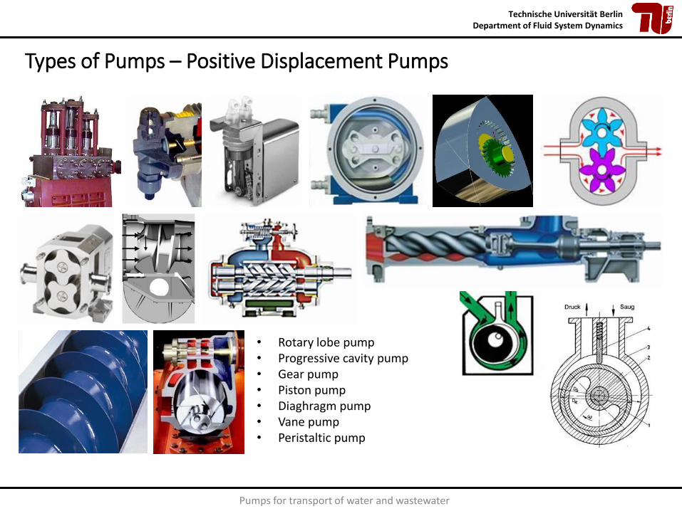
Types of Pumps – Positive Displacement Pumps
• Rotary lobe pump• Progressive cavity pump• Gear pump• Piston pump• Diaghragm pump• Vane pump• Peristaltic pump
Pumps for transport of water and wastewater

Technische Universität BerlinDepartment of Fluid System Dynamics
Types of pumps – Centrifugal pumps
• Radial flow pumps• Axial flow pumps• Mixed flow pumps
Special designs, e.g. • Vortex pump• Self-priming pump
Pumps for transport of water and wastewater
Pic
ture
s:K
SB
Pic
ture
s:K
SB
Pic
ture
s:K
SB
Pic
ture
s:K
SB

Technische Universität BerlinDepartment of Fluid System Dynamics
Types of Pumps – Special Designs
• Liquid ring pump• Side channel pump• Jet pump• Airlift pump• Hydraulic ram
Pumps for transport of water and wastewater

Technische Universität BerlinDepartment of Fluid System Dynamics
21.05.2019 Pumping systems in the wastewater infrastructure 6
Operation Areas of Different Pumps‘
head [m]
10
10 000
1000
100
10
100 1000 10 000 100 000
capacity [m3/h]
axial pump
diagonal pump
multistage centrifugal pump
Single stage centrifugal pump
rotating displacement pump
displacement
pumps
single stage,
double flow pump
side channel
pump,
vane pump

Technische Universität BerlinDepartment of Fluid System Dynamics
Picture: After [TW90]
Characteristics: centrifugal/positive displacement pump
7

Technische Universität BerlinDepartment of Fluid System Dynamics
Picture: After [TW90]
Work principle
positive displacement flow lifting lift (force)
design piston pump diaphragm
pump progressive cavity pump
centrifugal pump screw pump chain pump airlift pump
single stage
multi-stage
sketch
H-Q- curve
M- n- curve
-
H head
Q flow rate
−
−
M torque
n rotation speed
−
−
Overview of Different Pump Designs
8
n nn n n
n

Technische Universität BerlinDepartment of Fluid System Dynamics
Definition of a Fluid Flow Machine
Mechanical power P is transfered into hydraulic power Pu by an impeller which
deflects the fluid‘s flow direction.
Mechanic: P = M w
Hydraulic: Pu = g H Q
𝑷 = 𝑷𝒖 + 𝑷𝒋
U
i
M torque
angular speed
P required power
P hydraulic power
P losses of power
density of the fluid
g gravity acceleration
Q flow rate
H head
−
w −
−
−
−
−
−
−
−

Technische Universität BerlinDepartment of Fluid System Dynamics
Seal
Shaft
Bearing
housing
Impeller
Discharge
flange
Spiral
casing
Suction
flange
Basic Components of a centrifugal Pump
Picture: Flowserve

Technische Universität BerlinDepartment of Fluid System Dynamics
Impeller with Nomenclature
Meridional Section Plan view
Picture: After [GU10] p.40

Technische Universität BerlinDepartment of Fluid System Dynamics
How does a centrifugal pump work?

Technische Universität BerlinDepartment of Fluid System Dynamics
How does the pump work?

Technische Universität BerlinDepartment of Fluid System Dynamics
How does the pump work?
𝐻𝐸 =1
𝑔𝑢2. 𝑣3𝑢 − 𝑢1. 𝑣0𝑢
𝐻𝐸 =1
𝑔𝑢2 ⋅ 𝑣3𝑢 (𝑓𝑜𝑟 𝛼0 = 90° → 𝑣0𝑢 = 0 𝑚
𝑠)
Picture: After [PF05] p.25

Technische Universität BerlinDepartment of Fluid System Dynamics
Picture: After [PF05] p.25
Centrifugal partDeceleration of rel. velocity
Acceleration of abs. velocity
𝐻𝐸 =1
2𝑔𝑢22 − 𝑢1
2 + 𝑤02 − 𝑤3
2 + 𝑣32 − 𝑣0
2
𝐻𝐸 =1
𝑔𝑢2. 𝑣3𝑢 − 𝑢1. 𝑣0𝑢
𝐻𝐸 - Euler Head [m]𝑔 - Gravity acceleration [m/s2]𝑢 - circumferential speed [m/s]𝑣 - Velocity [m/s]
The Euler Turbine Equation (Euler's equation
of fluid machines)
Technische Universität BerlinDepartment of Fluid System Dynamics
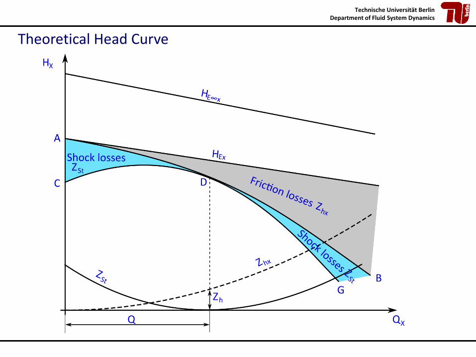
Theoretical Head Curve

Technische Universität BerlinDepartment of Fluid System Dynamics
Impellers‘ and Pumps‘ Design
Picture: above [KSB89] p.171
Radial centrifugal pump Diagonal centrifugal pump Axial centrifugal pump
Radial impeller Diagonal impeller Axial impeller

Technische Universität BerlinDepartment of Fluid System Dynamics
Performance Curves for Different Designs

Technische Universität BerlinDepartment of Fluid System Dynamics
Multistage

Technische Universität BerlinDepartment of Fluid System Dynamics
Multistage
Picture: Sulzer

Technische Universität BerlinDepartment of Fluid System Dynamics
Multiflow

Technische Universität BerlinDepartment of Fluid System Dynamics
Double Suction Pump
Pictures: Flowserve
Technische Universität BerlinDepartment of Fluid System Dynamics
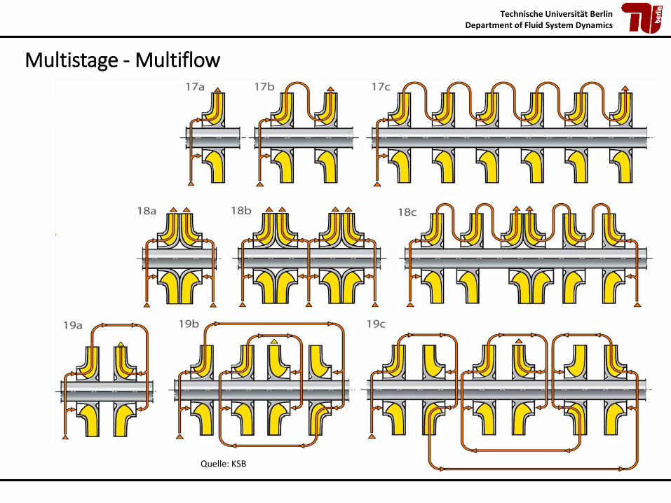
Multistage - Multiflow
Quelle: KSB

Technische Universität BerlinDepartment of Fluid System Dynamics
Designs of Pumps- Examples
single stage,
single flow
centrifugal pump
single stage, double
flow centrifugal pump
Single flow, multi-
stage centrifugal
pump
Pictures: Flowserve

Technische Universität BerlinDepartment of Fluid System Dynamics
Designs of Pumps- Examples
Pictures: Flowserve
axial centrifugal pump
diagonal
centrifugal pump
submersible pump
Vertical turbine
pump

Technische Universität BerlinDepartment of Fluid System Dynamics
Pump & System

Technische Universität BerlinDepartment of Fluid System Dynamics
System‘s Head Requirement
𝐻𝐴 =𝑝𝐷 − 𝑝𝑆𝜌. 𝑔
+𝑣𝐷
2− 𝑣𝑆
2
2 ∙ 𝑔+ ∆𝑍
HA – System Head [m]p – pressure [N/m²]g – gravity acceleration [m/s²] – density [kg/m³]v – velocity [m/s]Dz – difference of height [m]
D – discharge
S – suction

Technische Universität BerlinDepartment of Fluid System Dynamics
Bezugs-niveau
𝑝𝑎𝑚𝑏
𝑝1
1 𝐷𝑆 2
𝑌𝐽1𝑆
𝑔 ⋅ 𝑧1
𝑝1 + 𝑝𝑎𝑚𝑏 /𝜌
𝑣12/2
𝑔 ⋅ 𝑧𝑠
(𝑝𝑠 + 𝑝𝑎𝑚𝑏)/𝜌
𝑣𝑆2/2
𝑌 = 𝑔.𝐻
𝑔 ⋅ 𝑧𝐷
𝑣𝐷2/2
(𝑝𝐷 + 𝑝𝑎𝑚𝑏)/𝜌
𝑌𝐽𝐷2
𝑔 ⋅ 𝑧2
𝑣22/2
(𝑝2 + 𝑝𝑎𝑚𝑏)/𝜌
𝑝2
Energy
Pump
System‘s Head Requirement

Technische Universität BerlinDepartment of Fluid System Dynamics
Q
H
No static head
Circulation pump
Q
H
~ Q2
No dynamic head
Fire pump
v2
Variable curve
Filling a tank
H
Q
Curve at the
end of pumping
Curve at the
beginning of
pumping
start
stop
stop
start
HA
HA
Examples of System Characteristic Curves

Technische Universität BerlinDepartment of Fluid System Dynamics
Choosing the Pumph
ead
H
capacity Q
HA
Speed n=const.
Hs
tati
cH
dyn
amic
H
→ No tolerances !→ No margins !
The required pump head must be equal to the system resistance at that flow rate where the pump reaches its best efficiency.
JgeoCP Hg
vv
g
ppHH +
−+
−+=
2
2
1
2
212
AoptCP HQH =)(

Technische Universität BerlinDepartment of Fluid System Dynamics
Qmin 0.5 * QBep
Qmax 1.2 * QBep
Q
H
QmaxQBEPQmin
H
hWorking outside of the
operation area causes:
• vibrations
• cavitation
• recirculation
• …
21.05.2019
Recommended operation area
BEP
Shutoff
Choosing the Right Pump

Technische Universität BerlinDepartment of Fluid System Dynamics
Pump Curve Sensitivity & Reliability of Centrifugal Pumps
32
Picture: After Judy Hodgson,Du Pont

Technische Universität BerlinDepartment of Fluid System Dynamics
Choosing the Right Pump
33
1. Mark the calculated Q, H-values in the performance characteristics for the pump series (above)
2. Find the right pump size (here: 65-250)3. Mark the calculated Q,H-values in the performance characteristics
for the right pump size and find the correct pump diameter (right top, here 255 mm), the NPSHr (right middle, here 2.8 m), and the shaft power (right bottom, here 28 kW)

Technische Universität BerlinDepartment of Fluid System Dynamics
Pump Control – Adjusting pump performance
Sometimes it is not possible to select a pump that works at the optimum duty point because the requirements of the system. Therefore, it can be necessary to adjust the pump performance
The most common methods for controlling flow through a pumping system:• Throttle control• Bypass control• Speed control• Modifying impeller diameter
The selection of the most appropriate pump flow control method depends on:• Fluid properties,• System layout• System flow/pressure requirements over time• System size
can be carried out continuously during operation

Technische Universität BerlinDepartment of Fluid System Dynamics
Pump Control – Control by modifying impeller diameter
Reducing the impeller diameter cannot be done while the pump is operating.
Reducing the diameter D2
The relation between the impeller diameter and the pump performance:
𝑸𝒏
𝑸𝒙=
𝑫𝒏
𝑫𝒙
𝒙
𝑯𝒏
𝑯𝒙=
𝑫𝒏
𝑫𝒙
𝒙
X 2

Technische Universität BerlinDepartment of Fluid System Dynamics
Pump Control – By Throttling
Hp=Hs+Hv

Technische Universität BerlinDepartment of Fluid System Dynamics
Pump Control – By Bypass
Qp=Qs+QBP
Technische Universität BerlinDepartment of Fluid System Dynamics
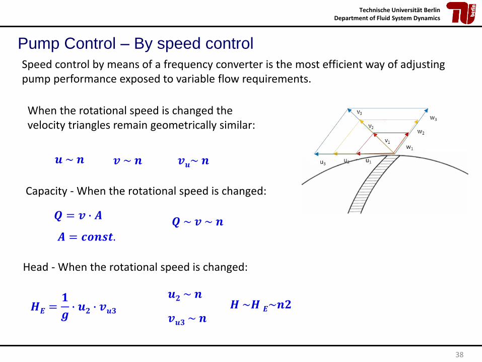
38
Capacity - When the rotational speed is changed:
𝑸 = 𝒗 ∙ 𝑨𝑸 ~ 𝒗 ~ 𝒏
Head - When the rotational speed is changed:
𝒖 ~ 𝒏 𝒗 ~ 𝒏 𝒗𝒖~ 𝒏
𝑨 = 𝒄𝒐𝒏𝒔𝒕.
𝑯𝑬 =𝟏
𝒈∙ 𝒖𝟐 ∙ 𝒗𝒖𝟑
𝒖𝟐 ~ 𝒏
𝒗𝒖𝟑 ~ 𝒏𝑯 ~𝑯 𝑬~𝒏𝟐
Pump Control – By speed control
Speed control by means of a frequency converter is the most efficient way of adjusting pump performance exposed to variable flow requirements.
When the rotational speed is changed the velocity triangles remain geometrically similar:

Technische Universität BerlinDepartment of Fluid System Dynamics
Can be written as:
39
𝑸 ~ 𝒏 𝑸 = 𝑲𝟏 ∙ 𝒏 𝑯 ~ 𝒏𝟐 𝑯 = 𝑲𝟐 ∙ 𝒏𝟐
Substituting the rotational speed n in the equation of H:
𝑯 = 𝑲𝟐 ∙𝑸
𝑲𝟏
𝟐
=𝑲𝟐
𝑲𝟏𝟐∙ 𝑸𝟐 𝑯 = 𝑲 ∙ 𝑸𝟐
Pump Control – By speed Control
𝑸𝟏
𝑸𝟐=𝒏𝟏𝒏𝟐
𝑯𝟏
𝑯𝟐=
𝒏𝟏𝒏𝟐
𝟐

Technische Universität BerlinDepartment of Fluid System Dynamics
40
• Rotational Speed changes → operational point moves along the parabola• If similarity rule applies multiple times → head capacity curve for new rotational
speed is found
n1
n2
n3
n1n2n3
capacitycapacity
efficiencyhead
H=K’ Q²
H=K’’ Q²
H=K’’’ Q²
Pump Control – By speed Control

Technische Universität BerlinDepartment of Fluid System Dynamics
Head
H
Capacity Q
h = 75%
h = 50%
h = 50%
h = 30%
h = 30%
Qmin
Hst
atic
Hd
ynam
ic
system curve
Head- capacity curve:
H = f ( Q, b2, hhydr, HShock, ….)
System characteristic curve:
21
2 2
static dynamic
A static dynamic
A
H H
H H H
p vH z
g g
= +
D= + D +
2
AH const. v= +
Shell – Curve of a Pump

Technische Universität BerlinDepartment of Fluid System Dynamics
Operation of Pumps
Q1=Q2
Q
H
H1+H2
Q1=Q2
H1,H2
Q2Q1
Q1+Q2 H
QQ1+Q2
H1=H2Parallel Operation of Pumps
Series Operation of Pumps
Technische Universität BerlinDepartment of Fluid System Dynamics
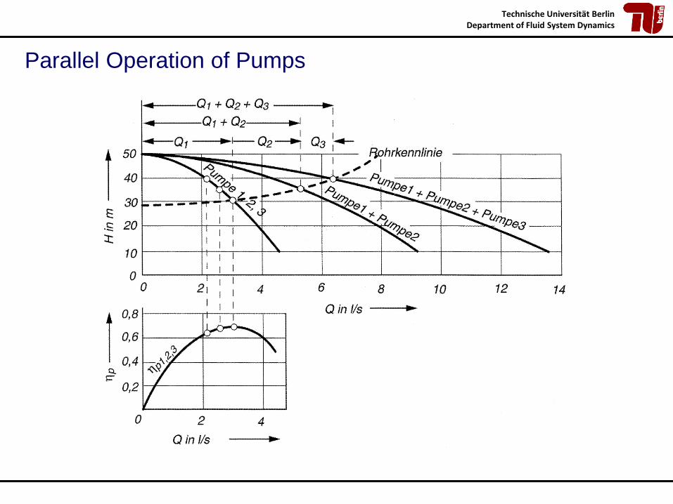
Parallel Operation of Pumps

Technische Universität BerlinDepartment of Fluid System Dynamics
Cavitation

Technische Universität BerlinDepartment of Fluid System Dynamics
Cavitation
Detailed view on
cavitation damages
Impeller with
cavitation damages

Technische Universität BerlinDepartment of Fluid System Dynamics
Cavitation process:
Pressure drop below vapour pressureplus
increase of pressure=> Collapse of Vapour Bubbles
Cavitation

Technische Universität BerlinDepartment of Fluid System Dynamics
Pump‘s Spots of increased Cavitation Risk
Leading edge of
the impeller
gap
gap
Leading edge of the diffuser

Technische Universität BerlinDepartment of Fluid System Dynamics
NPSHA = Net Positive Suction Head Available
Cavitation - NPSHA
𝑁𝑃𝑆𝐻𝐴 = 𝑍𝑠 +𝑃𝑆 − 𝑃𝐷𝜌 ∙ 𝑔
+𝑉𝑠
2
2 ∙ 𝑔
𝑁𝑃𝑆𝐻𝐴 = 𝑍𝑒 +𝑃𝑒 − 𝑃𝐷𝜌 ∙ 𝑔
+𝑉𝑒
2
2 ∙ 𝑔−𝐻𝑉𝑆

Technische Universität BerlinDepartment of Fluid System Dynamics
A Pump System‘s Head
g H
2
2
2
v
2 bp p+
IIg z
II bp p+
2
2
IIv
I bp p+
2g z1g z
Ig z
2,J IIg H
1,J Ig H
1 b Dp p p+ −
2
1
2
vI bp p+
2
1
2
v
1 2 III
energy line
pressure line
netto energy line
reference line
2
2
Iv
Picture: After [KSB89] p.289
pV
NPSHA

Technische Universität BerlinDepartment of Fluid System Dynamics
NPSHR = Net Positive Suction Head Required,minimum required netto suction head
Cavitation - NPSHR
1
2
λ 1.1 1.2
λ 0.2 0.3
0av absolute velocity just before
the inlet edge of the impeller
−
0aw relative velocity just before
the inlet edge of the impeller
−
𝑁𝑃𝑆𝐻𝑅 = 𝜆1𝑉0𝑎
2
2 ∙ 𝑔+ 𝜆2
𝑊0𝑎
2
2 ∙ 𝑔≈ 0.3 … . 0.5 ∙ 𝑛 ∙ 𝑄

Technische Universität BerlinDepartment of Fluid System Dynamics
Cavitation - NPSH

Technische Universität BerlinDepartment of Fluid System Dynamics
1 Cooling or heating coils
2 Stilling screens
3 To vacuum or pressure control
4 Spray nozzle for liquid de-aeration
5 Flowmeter
6 Flow control valve
7 Isolating valve
8 Measuring point for gas content
9 Test pump
[ISO 9906]
H100%
NPSHANPSH3%
DH
Q = constant
n = constant
H
Cavitation – Measurement of NPSH3%

Technische Universität BerlinDepartment of Fluid System Dynamics
Cavitation – Measurement of NPSH

Technische Universität BerlinDepartment of Fluid System Dynamics
Cavitation – Measurement of NPSH
B=1
Q/Qopt=1,0

Technische Universität BerlinDepartment of Fluid System Dynamics
Cavitation – Measurement of NPSH

Technische Universität BerlinDepartment of Fluid System Dynamics
NPSHA
Recirculation flow,
Pre rotationIndex “St”-
for
shockless
entrance
Cavitation – Measurement of NPSH

Technische Universität BerlinDepartment of Fluid System Dynamics
Head- capacity-
curve
NPSHANPSH
HNormal trend of the
head capacity curve if
NPSHA ≥ NPSHR
the head- capacity-
curve drops off if
NPSHA < NPSHR
NPSHR
Cavitation - NPSH
To avoid cavitation: NPSHA ≥ NPSHR
57

Technische Universität BerlinDepartment of Fluid System Dynamics
1. Know the pumping system’s cavitation behaviour well (NPSHA)
2. Know the pump’s suction behaviour well (NPSHR)
3. Use cavitation resistant materials
4. Supply suction nozzle with a bit of air (mechanic and noise damping)
5. Reduce rotation speed
6. Optimize the angle on the blade’s leading edge
7. Unify the velocity in the suction nozzle
Actions to actively avoid Cavitation

Technische Universität BerlinDepartment of Fluid System Dynamics
Prof. Dr.-Ing. P.U. Thamsen
Technical University Berlin
Thank you for your attention !