hydraulic stacker – model no. mn397 - kleton · note: do not use the platform stacker before...
TRANSCRIPT

Note: Do not use the platform stacker before reading and understanding these operation instructions.
HYDRAULIC STACKER – Model No. MN397
Operating Instructions and Parts List
1
Thank you for using platform stacker. Your stacker is made of high quality steel and is designed for the
horizontal lifting and transport of loads on a pallet or standardized containers on a level, fixed base. For
your safety and correct operation, please carefully read this instruction before using it.
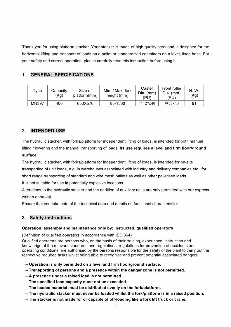
1. GENERAL SPECIFICATIONS
Type
Capacity (Kg)
Size of platform(mm)
Min. / Max. fork height (mm)
Caster Dia. (mm)
(PU)
Front roller Dia. (mm)
(PU)
N. W. (Kg)
MN397 400 650X576 85-1500 Φ127x40 Φ75x40 91
2. INTENDED USE
The hydraulic stacker, with forks/platform for independent lifting of loads, is intended for both manual
lifting / lowering and the manual transporting of loads. Its use requires a level and firm floor/ground
surface.
The hydraulic stacker, with forks/platform for independent lifting of loads, is intended for on-site
transporting of unit loads, e.g. in warehouses associated with industry and delivery companies etc., for
short range transporting of standard and wire mesh pallets as well as other palletised loads.
It is not suitable for use in potentially explosive locations.
Alterations to the hydraulic stacker and the addition of auxiliary units are only permitted with our express
written approval.
Ensure that you take note of the technical data and details on functional characteristics!
3. Safety instructions
Operation, assembly and maintenance only by: Instructed, qualified operators
(Definition of qualified operators in accordance with IEC 364) Qualified operators are persons who, on the basis of their training, experience, instruction and knowledge of the relevant standards and regulations, regulations for prevention of accidents and operating conditions, are authorised by the persons responsible for the safety of the plant to carry out the respective required tasks whilst being able to recognise and prevent potential associated dangers.
– Operation is only permitted on a level and firm floor/ground surface. – Transporting of persons and a presence within the danger zone is not permitted. – A presence under a raised load is not permitted. – The specified load capacity must not be exceeded. – The loaded material must be distributed evenly on the fork/platform. – The hydraulic stacker must never be loaded whilst the fork/platform is in a raised position. – The stacker is not made for or capable of off-loading like a fork lift truck or crane.

2
– Never leave the load unattended in a raised position. – Never reach into moving parts. – Defects are to be dealt with competently as soon as they become apparent. – Only use genuine spare parts.
Inspections In accordance with Section 37 of the BGV D27 the hydraulic stacker must be inspected by a competent technical expert at least once per year, and otherwise as required. We recommend that you record the results of the inspections in an inspection book. 4. Operating instructions Functional description The fork/platform stacker is a manually-operated hydraulic device.
Handling Before taking into operation, check:
perfect function of the operating elements function of the parking brake state of the travelling rollers and roller axles load chains for adjustment, chain tension and wear
Parking brake One or two steering wheel of the hydraulic stacker is equipped with a parking brake. For depositing, actuate the parking brake. Picking up a load Check that the load does not exceed the loading capacity of the hydraulic stacker. Roll the hydraulic stacker slowly up to the pallet/load. Roll the fork prongs under the pallet until the back end of the fork rests against the load (pallet). Lift the load by executing the pumping movements. The load must be evenly distributed across both prongs of the fork / platform. The load centre of gravity must not be exceeded. Moving with the load As only a parking brake is provided, the hydraulic stacker must not be operated uphill and on gradients. Travel with the load in lowest possible position in consideration of the floor clearance under the load. The load should be moved with lifted fork / platform only for stacking and depositing on even surface. Travel with steady speed adapted to the load and the floor conditions. For depositing, actuate the parking brake. Setting the load down Stop just before the stacking area and lift the load in safe distance over the pile. Manoeuvre the load directly above the pile. Lower the load until platform is discharged. Lower the load by turning the release valve. Ensure safe reversing, move away and lower the platform. 5. MAINTENANCE

3
5.1 OIL Please check the oil level every six months. The oil can be hydraulic oil: ISO VG32, its viscosity should be 30cSt at 400 C, total volume is about 2.0lt. 5.2 TO BANISH THE AIR The air may come into the hydraulic oil because of transportation or pump in upset position. It can cause that the forks do not elevate while pumping in the RAISE position. The air can be removed in the following way: let the control handle (FP216) on the LOWER position, then move the pedal (FP242) up and down for several times. 5.3 DAILY CHECK AND MAINTENANCE Daily check of the stacker can limit wear as much as possible. Special attention should be paid to the wheels, the axles, as thread, rags, etc. It may block the wheels. The forks should be unloaded and lowered in the lowest position when the job is over. 5.4 LUBRICATION All bearings and shafts are provided with long-life grease at the factory. You only need provide with long-life grease at monthly intervals or after each time the truck is cleaned thoroughly to the lubrication points. 5.5. Inspection and maintenance instructions Safety warning: Before inspection and maintenance work is carried out, appropriate measures should be taken to remove all loads from the platform stacker.
Maintenance and inspection work Inspection intervals Check operating elements for faultless operation.
Daily or each time before use
Check condition of the travelling rollers and roller axles Check the firmness of the supply and the tension of the chain Check the chain, if necessary grease Grease joints and bearings
monthly Check functioning of wheels and rollers Check the level of the hydraulic oil with forks completely lowered and the stacker in horizontal position.
Every 3 months
Check hydraulic system for leakage (Is the top lifting height reached effortlessly?) Check the adjusting of the lifting chain and of the movement chain, if necessary adjust, clean and grease Check the set-up of the control lever Check all screw and bolt connections for tightness Grease joints and bearings Check functioning and turning capability of wheels and rollers Check all parts of the hydraulic stacker for wear and replace defective parts where necessary
Annually Change oil in the hydraulic system (suck the oil out of the tank, refill with new oil) -Ventilate the hydraulic system- Check readability of type plate. Authorize inspection by competent technical expert
The service life of your hydraulic stacker is limited. Worn parts must be renewed in good time.
4
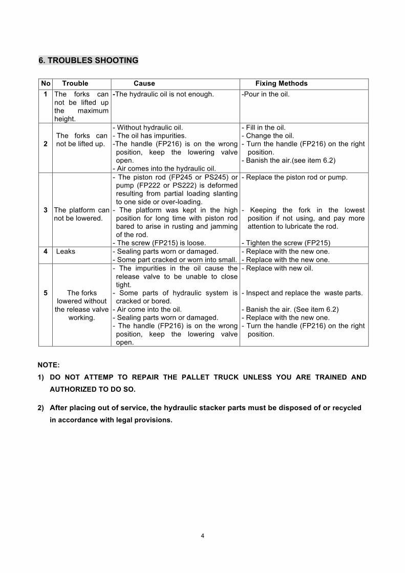
6. TROUBLES SHOOTING No Trouble Cause Fixing Methods 1 The forks can
not be lifted up the maximum height.
-The hydraulic oil is not enough. -Pour in the oil.
2
The forks can not be lifted up.
- Without hydraulic oil. - The oil has impurities. -The handle (FP216) is on the wrong position, keep the lowering valve open.
- Air comes into the hydraulic oil.
- Fill in the oil. - Change the oil. - Turn the handle (FP216) on the right
position. - Banish the air.(see item 6.2)
3
The platform can not be lowered.
- The piston rod (FP245 or PS245) or pump (FP222 or PS222) is deformed resulting from partial loading slanting to one side or over-loading.
- The platform was kept in the high position for long time with piston rod bared to arise in rusting and jamming of the rod.
- The screw (FP215) is loose.
- Replace the piston rod or pump. - Keeping the fork in the lowest
position if not using, and pay more attention to lubricate the rod.
- Tighten the screw (FP215)
4 Leaks - Sealing parts worn or damaged. - Some part cracked or worn into small.
- Replace with the new one. - Replace with the new one.
5
The forks lowered without
the release valve working.
- The impurities in the oil cause the release valve to be unable to close tight.
- Some parts of hydraulic system is cracked or bored.
- Air come into the oil. - Sealing parts worn or damaged. - The handle (FP216) is on the wrong position, keep the lowering valve open.
- Replace with new oil. - Inspect and replace the waste parts. - Banish the air. (See item 6.2) - Replace with the new one. - Turn the handle (FP216) on the right
position.
NOTE:
1) DO NOT ATTEMP TO REPAIR THE PALLET TRUCK UNLESS YOU ARE TRAINED AND AUTHORIZED TO DO SO.
2) After placing out of service, the hydraulic stacker parts must be disposed of or recycled in accordance with legal provisions.
5
6
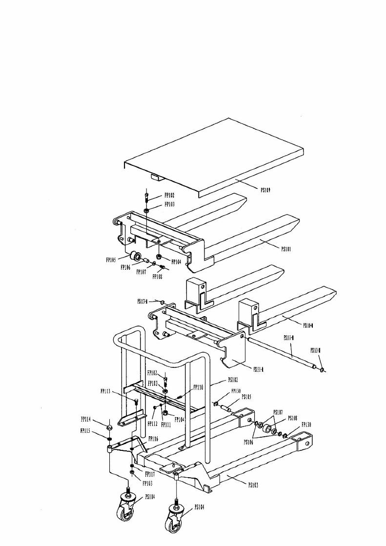
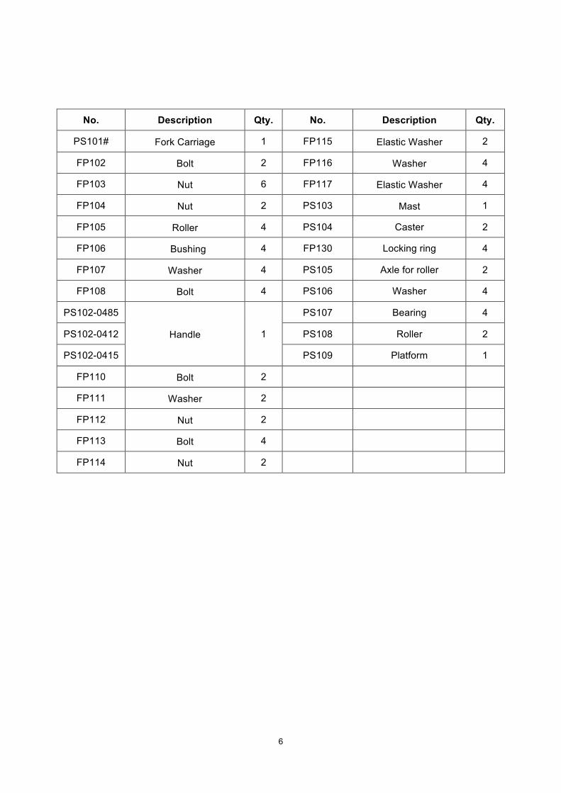
No. Description Qty. No. Description Qty.
PS101# Fork Carriage 1 FP115 Elastic Washer 2
FP102 Bolt 2 FP116 Washer 4
FP103 Nut 6 FP117 Elastic Washer 4
FP104 Nut 2 PS103 Mast 1
FP105 Roller 4 PS104 Caster 2
FP106 Bushing 4 FP130 Locking ring 4
FP107 Washer 4 PS105 Axle for roller 2
FP108 Bolt 4 PS106 Washer 4
PS102-0485
Handle 1
PS107 Bearing 4
PS102-0412 PS108 Roller 2
PS102-0415 PS109 Platform 1
FP110 Bolt 2
FP111 Washer 2
FP112 Nut 2
FP113 Bolt 4
FP114 Nut 2

7

8
No. Description Qty. No. Description Qty.
FP201 Pump Piston Rod 1 FP233 Pressure Roller 1 FP202 Spring Cap 1 FP234 Bushing 1 FP203 Spring 1 FP235 Shaft 1 FP204 O-Ring 2 FP236 Nut 1 FP205 Washer 1 FP237 Elastic Washer 1 FP206 Oil-holder 2 FP238 Steel Ball 1 FP207 Shaft 1 FP239 Nut 1 FP208 Steel Ball 3 FP240 Bolt 1 FP209 O-Ring 2 FP241 Locking Ring 1 FP210 Bolt 4 FP242 Footplate 1 FP211 Sleeve 1 FP243 Seat 1 FP212 Shaft 1 FP244 Sleeve 1 FP213 Spring 1 PS245-0485
Lifting Piston Rod 1 FP214 Sleeve 1 PS245-0412 FP215 Bolt 1 PS245-0415 FP216 Control Handle 1 FP246 Linking Chain 2 FP217 Dust Ring 1 PS247-0485
Chain 1 FP218 O-Ring 2 PS247-0485 FP219 Washer 1 PS247-0485 FP220 Seal Washer 1 FP248 Cover 1 FP221 Bolt 1 FP249 Bolt 1
PS222-0485 Body of Pump 1
FP250 Cap 1 PS222-0412 FP251 Shaft 1 PS222-0415 FP252 Locking Ring 2
FP223 Valve Spindle of Pump 1 FP253 Chain gear 1 FP224 Spring 2 FP254 Bushing 2 FP225 Pin 1 FP255 Bracket 1 FP226 Adjust Screw 2 FP256 Screw 1 FP227 O-Ring 1 FP257 Seal washer 1 FP228 Bolt 1 FP258 Sleeve 1 FP229 Screw 2 FP259 Screw 1 FP230 Seal Washer 2 FP260 Seat of valve 1 FP231 Spring 2 FP261 O - ring 1 FP232 Locking Ring 2