hydraulically driven pumps - harwood engineering … in hydraulically driven pumps, ... obtained...
TRANSCRIPT

Hydraulically Driven Pumps
DONALD H. NEWHALL
Harwood Engineering Co., Inc., Walpole, Mass.
Reprinted from INDUSTRIAL AND ENGINEERING CHEMISTRY, Vol. 49, Page 1949, December 1957 Copyright 1957 by the American Chemical Society and reprinted by permission of the copyright owner

Ind. Eng. Chem. 49, 1949-54 (1957)
Hydraulically Driven Pumps Excessive torque, side thrust, and friction make crank
driven pumps cumbersome and expensive at high pressures. But in hydraulically driven pumps, these effects are eliminated or minimized and higher pressures can be attained. Also, longer strokes are characteristic; therefore, rates of stress buildup are reduced in such areas as check valves and packing, which results in less maintenance and longer life. Without rotational inertia, controllability is increased which in turn increases safety.
Essentially continuous flow and high efficiencies can be obtained with a combination of double acting pumps.
DONALD H. NEWHALL
Harwood Engineering Co., Inc., Walpole, Mass.

~ .
. :JBI:Xv~::EI:
1 DONALD H. NEWHALL
Harwood Engineering Co., Inc., Walpole, Mass.
Hydraulically Driven Pumps The future need for higher pressure with consequent demand on equipment will make these pumps increasingly important
DEVELOPMENT oF THE hydraulic drive portioned so that fatigue and high stress reliable than its check valves. Two for high pressure piston pumps has been will not be a major problem. At higher of these are required for each plunger, a key factor in attaining high pressures pressures, more careful stress analysis is and for every cycle of stroking, each
needed if safety and long life are to be check valve must function once (open now found in commercially feasible achieved. This limits the choice of and close) with full range of applied systems. Compared to other forms of materials of construction, and it requires stress between zero and maximum. reciprocating pumps widely used at lower sound metallurgical practice. The higher the rate of stroking, the pressures, this pump has received little Reciprocating pumps impose a stress faster the check valves must seat, and attention in the technical literature. cycle with each piston stroke. To hence, the greater the impact or battering It is often called an intensifter and not pump a given quantity of fluid, the of the seat. This can be serious indeed only handles large differences between number of strokes required and, there- at high pressure. Large displacement intake and discharge pressures, but fore, the number of stress cycles imposed, again, therefore, lengthens valve life. makes easier certain design problems is inversely proportional to piston dis- Furthermore, in many pumps the
placement. The probability of fatigue cylinder block houses not only plungers, which are multiplied at high pressures. failure is a function of the number of but also ports for intake and discharge,
This hydraulically driven pump is cycles of applied stress so that, other as well as check valves. The system of useful at pressures as low as 5000 pounds things being equal, the larger the dis- holes and cross-drillings necessary in per square inch~far lower than origi- placement the better. this design creates complicated patterns nallyplanned-and up to 200,000 pounds. Check Valves. A pump is no more of combined stress that invite early and It has high efficiency and considering its large capacity, it is physically small. Nature of the hydraulic drive itself makes the pump easily adaptable to automatic control, and its controllability simplifies the problems of safety and maintenance. It will pump both liquids and gases. Because of its flexibility, it is constantly being adapted to new applications in chemical and physical processing.
Usually, high pressures of about 200,000 pounds are used for research, but they also have a few important industrial applications-e.g., in autofrettage (12) or cold-working of cannon (7) and other high pressure equipment. Another important use is in strengthening materials used under intermediate pressures of about 35,000 pounds which are now common in certain chemical processes. High pressure also makes it possible to test pressure-carrying parts to destruction for determining actual safety factors. The increasing industrial use of apparatus for high pressure suggests that high pressure technology will have wide commercial use.
All high pressure pumps now used are reciprocating piston pumps. Others employing such mechanisms as gears, vanes, and impellers, cannot operate at the high stress levels or handle leakage resulting from mechanical deformation and pressure differences characteristic of high pressure systems. Reciprocating pumps of all designs have four problems in common.
Cycling Stresses. If pressure does not exceed 20,000 pounds per square inch, almost any design may be pro-
A. B. c. D.
PROCESS
INTAKE
A
P(HIGH PRESSURE)
p (LOW PRESSURE)
PROCESS
__.DISCHARGE
H
Figure 1. Single-acting pump with associated low pressure system
High pressure check valves High pressure cylinder High pressure packing High pressure piston of area, a
Neglecting friction, P a = Ap
E. Low pressure cylinder F. Low pressure piston of area, A G. Manual directional valve H. I.
Pressure gage Hydraulic oil pump, 2000 pounds per square
inch maximum
VOL. 49, NO. 12 • DECEMBER 1957 1949

PROCESS DISCHARGE--
DOUBLE- ACTING LOW PRESSURE
CYLINDER
_L Figure 2. Intensifier for Harwood single-acting pump
unpredictable fatigue failure. This design requires a major disassembly to reseat or service the check valves.
Packings. Regardless of the pump form, leakage across packings is a critical problem in design and maintenance, particularly with high pressure equipment. The speed of rubbing and the large forces present at high pressure cause friction which in turn produces heat. This is another reason for preferring large pistons and long strokes.
Different types of packings are available for use at high pressure. Many in common use have been described (2, 5, 14), but the packing design has to be chosen for the particular problem. So far, a universal packing to meet all conditions has not been found. Some of the useful packings can fail from alternating flexures resulting from frictional forces as the ram moves back and forth. Again, larger displacements and fewer strokes are advantageous.
Maintenance. Virtues of pump designs which require infrequent and brief downtime, are too well appreciated by experienced chemical engineers to dwell upon at length. In a good design, ease of repair and replacement are reflected sharply in the economics of plant operation.
The three previously discussed design problems are also maintenance problems, and in any good pump account for most of the downtime. But the finest equipment, if abused, will require other attention. A system assembled without adequate filtering, or without first cleaning its components, will certainly give trouble, regardless of quality. Besides adequate filtering, the equipment should be arranged for ready accessibility when cleaning and changing filters. Obviously, maintenance which is dependent on the number of strokes will be less when large pistons of long stroke are used.
Limitations of the Crank Drive
In all four considerations previously mentioned, the fewer piston strokes per
unit volume pumped, the longer the life, the less the hazard, and the smaller the maintenance problem. Therefore, pistons should be as large and stroke should be as long as consistent with good engineering practice and economy.
In mechanical crank-type pumps, cost soon becomes prohibitive as diameter and stroke of pistons increase. Force on the piston, and hence the torque on the crank, increases as the square of the diameter; and the torque increases again proportionally with the increase in stroke. The side thrust at the crossheads and journals rapidly becomes a serious design problem. For increased capacity, crank-type pumps can be driven faster, but increased speed quickly leads to these design difficulties. All crank devices are necessarily subject to these fundamental limitations.
Hydraulically Driven Pumps
In the hydraulically driven pump, large pistons of long stroke can be used to minimize these four critical design problems. It has a simple, direct, in-line drive with no cranks, eccentrics, or crosshead bearings to add friction and wear. Working on the intensifier principle, liquid pressure is applied to a piston of comparatively large area, which drives a piston of smaller area. The ratio of pressures at the two pistons is inversely proportional to their areas.
Single-Acting Pump. The simplest practical system of this type is a singleacting hydraulically driven pump (Figure
1). The drive portion is shown with Joint Industrial Conference (8) symbols, but for simplicity, the intensifier part is shown without constructional detail. The intensifier has two main partsthe low pressure, double-acting cylinder and the high pressure cylinder. The pistons in these cylinders are mechanically attached-the low pressure piston pushes the high pressure piston in a delivery stroke and pulls it in the return stroke. When low pressure is applied to the bottom face of the low pressure piston, oil, put on the top side by the previous return stroke, is exhausted at atmospheric pressure through the directional valve to the reservoir. At the end of the delivery stroke, the directional valve reverses the low pressure flow to the top of the low pressure piston, exhausting the oil on the bottom side to the reservoir at atmospheric pressure. During the return stroke, the highpressure process discharge check valve is closed and process fluid at the intake pressure fills the high pressure cylinder, readying it for the next delivery stroke. This is a convenient arrangement when only a few strokes are to be used at one time. An electrically operated, oilpiloted, directional valve can be used in place of that manually operated (Figure 1) to provide automatic reciprocation of the single-acting pump, if desired. The flow is still intermittent, with time lost in pumping down, or returning the pistons to the bottom of the stroke.
The intensifier portion is shown in Figure 2 with a yoke separating the low
DISCHARGE
---+ DOUBLE ACTING
INTENSIFIER
INTAKE ---+
G /J-+ot--+
Figure 3. This double-acting pump, including low pressure system, gives a continuous uniform flow
1950 INDUSTRIAL AND ENGINEERING CHEMISTRY

and high pressure cylinders. Here, a low pressure ram separates the low pressure and high pressure pistons. This ram is larger in diameter than the higher pressure piston, but considerably smaller than the low pressure piston. With this construction, the high pressure piston is never exposed to oil in the low pressure cylinder and thus hydraulic oil cannot contaminate the high pressure process fluid.
Double-Acting Pump. A continuous, uniform flow may be attained with the double-acting arrangement (Figure 3). While one of the double-acting pistons is delivering, the other cylinder is being charged during its intake stroke. This apparatus is a neat, compact assembly (Figure 4,A and B). While these units could be made to stroke with a manual four-way directional valve, they are almost invariably assembled for fully automatic operation. Meeting requirements for explosionproofing is conventional and the application of remote control is simple.
Design Problems in the Hydraulic Drive
In hydraulically driven reciprocating pumps like those discussed previously, the four principal design problems, common to all reciprocating piston pumps, are made easier. Moreover, these pumps are useful and economical at far lower pressures than originally planned.
Cyclical Stress. The hydraulic drive makes possible a symmetrical construction that minimizes stress concentrations that become so critical at high pressure. Since the high pressure heads of the
'"'"'"'"' A 1FT.
.... · .. .J
intensifier are cylindrical and free of geometric discontinuities, the only stress concentration remaining to cause concern is that characteristic of thick, hollow cylinders subjected to internal pressure. This stress system is classic (9) in the theory of elasticity, and considerable information has been published concerning various solutions (10, 72). Ordnance engineers for many years have worked on the same stress problems in guns which deal repeatedly with peak pressures of 38,000 pounds and higher. The techniques of strengthening tubes by autofrettage in monobloc cylinders and of compounding tubes by shrinkage techniques originated in ordnance development. Both these techniques, either singly or in combination, are used in manufacturing the high pressure ends of the intensifiers illustrated. Designs illustr.:tted are based on additional data ar.d on design practices somewhat beyond those reached in the ordance field ; pressures handled with this equipment are more than four times the peak pressure of cannon.
The favorably oriented stresses developed by these techniques extend endurance limits considerably beyond that anticipated with conventional design. The life of a pressure cylinder, normally limited by fatigue, may easily be trebled by favorably oriented residual stress. For pressures as high as 60,000 pounds, apparatus can have practically infinite life; this may be true even up to 80,000 pounds.
Over a 9-year period the Harwood Engineering Co. has been required toreplace only three high pressure heads, two of which were made from the same heat of steel, and failed in the same way after
HIGH PRESSURE
only a few pressure cycles. Failure occurred at localized metallurgical imperfections that were not revealed at inspection. The third failure resulted from hydrogen embrittlement when a pump made of alloy steel was used to pump hydrogen gas. Even though these pumps are in regular use, those operating at extremely high pressure have experienced only a few thousand cycles. Many of the pumps designed for 60,000 pounds and lower have had hundreds of thousands of stress cycles without failure. In fact, several of the pumps designed for 60,000 pounds have been used continuously for many months in fatigue studies of other apparatus where the frequencies of application have ranged from 20 to 50 cycles per minute.
Check Valves. In addition to lessening wear on the check valves by reducing the number of strokes per unit volume pumped, this hydraulic-drive system eliminates the stress concentrations resulting from cross-drillings for pressure pons and check valves by the simple device of using external check valves connected by piping to the high pressure head. Large-diameter pistons and long strokes make the effect of lost volume (clearance volume) in the short piping to the check valves even smaller than normally encountered with other pumps. Ratio of lost volume to total volume of the cylinder-i.e., volume between the piston and the check valve-determines volumetric efficiency. In any case, with liquid pumps, volumetric efficiency is usually not a serious concern. Gases at high pressure tend to behave like liquids; hence, the problem of volumetric efficiency is not so acute in the final compression stage as it is in the first stage where the wasted work of compression is relatively more important.
Packings. Life of a packing is lengthened by lower piston speed, fewer reversals of direction, as well as the tendency of liquids to be lubricating at high pressure. Water at room tern-
l.L.LLJ B 1FT.
Figure 4. The Harwood double-acting high pressure pump is a neat compact assembly
A. DA-4 B. DA-14; separate reservoir not shown
VOL. 49, NO. 12 • DECEMBER 1957 1951
Ill
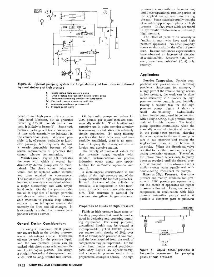
Figure 5. Special pumping system for large delivery at low pressure followed by small delivery at high pressure
I. Single·acting high pressure pump II. Double-acting hydraulically driven intake pump Ill. Autoclave containing powder for compaction IV. Electronic pressure recorder-indicator V. Manganin resistance pressure cell VI. Pressure relief valve
perature and high pressure is a surprisingly good lubricant, but at pressures exceeding 135,000 pounds per square inch, it is likely to freeze (3). Some high pressure packings will last a fair amount of time with essentially no lubricant in the conventional sense. Wherever possible, it is, of course, desirable to lubricate packings, but frequently the task is nearly impossible because of the severe requirements of processes that cannot tolerate contamination.
Maintenance. Figure 4,B, illustrates the ease with which a typical hydraulically driven pump can be maintained. The check valves, being external, can be replaced within minutes and then repaired at convenience. The replacement of high pressure packings and closures is accomplished without a major disassembly and with simple hand tools. On the low pressure side, the oil is kept free of foreign particles and abrasive matter by filters. Reasonable attention to general shop tidiness reduces to an infrequent routine the necessity for filter and oil changes. It is extremely rare that low pressure components require service.
General Design Considerations
By using a maximum 2000 pounds per square inch as the driving pressure, several advantages accrue. Hydraulic oil can be used for the pressure liquid and the low pressure piston can be packed with piston rings as in automobile and Diesel engine pistons. The design is straight-forward and time-proved, and lends itself to long, trouble-free service.
Oil hydraulic pumps and valves for 2000 pounds per square inch are commercially available. Their familiar and extensive use in quite complex circuitry is reassuring in evaluating this relatively simple application. By using filtering practices that have been long and successfully established, there is no problem in keeping the driving oil free of foreign and abrasive matter.
The variety of functional values for that pressure range, together with standard instrumentation for process industries, opens many new opportunities for automatic operation and control.
A metallurgical consideration in the design of the high pressure end of the pump determines the limit of piston size. If wall thickness of the cylinder is excessive, it is impossible in heat treatment, to quench to a martensitic structure. This structure is essential for maximum strength and fatigue resistance.
Properties of Fluids at High Pressure
Fluids at high pressure have some interesting properties that must be understood in designing and operating pumping equipment. For many purposes, unconfined liquids may be treated as incompressible; yet at 100,000 pounds per square inch, density of 20% over that at atmospheric pressure is common, and the heat acquired from the work of compression may be important. On the other hand, under normal conditions, gases obey Boyle's law approximately, and change in pressure results in a proportional change in density. At high
1952 INDUSTRIAL AND ENGINEERING CHEMISTRY
pressures, compressibility becomes less, and a correspondingly smaller portion of the applied energy goes into heating the gas. Some materials usually thought of as solids appear quite plastic at high pressure. In fact, some solids are useful in hydrostatic transmission of extremely high pressure.
The effect of pressure on viscosity is familiar to most who have used high pressure apparatus. No other property shows so dramatically the effect of pressure. In some substances, experimenters have observed an increase of viscosity of a millionfold. Extensive data, however, have been published (1, 4) only recently.
Applications
Powder Compaction. Powder compactions also present some interesting problems. Sometimes, for example, if a large part of the volume change occurs at low pressure, the work can be done more efficiently if a moderately high pressure intake pump is used initially, leaving a smaller task for the high pressure pump. Figure 5 shows a small double-acting, hydraulically driven, intake pump used in conjunction with a single-acting, high pressure pump designed for this purpose. The intake pump operates continuously when the manually operated directional valve is in the pump-down position, charging the whole system to the maximum pressure it can generate and setting the single-acting piston at the bottom of its stroke. When the directional valve is shifted to the other position, the singleacting intensifier operates. Thereafter, the intake pump serves only to pump down as required until the desired pressure is reached. It is obvious that a similar system works equally well with double-acting intensifiers for pumps.
Gases at High Pressure. Gas compressors are readily available for pressures to 2500 pounds per square inch, but the choice of apparatus for higher pressures is limited. Using low pressure compressors in conjunction with high pressure intensifier pumps makes it possible to compress gases to pressures
TO L.?
orne:
Figure 6. liquid piston principle is frequently convenient for pumping gases at high pressures

INTAKE
TO DRIVE CIRCUIT
A. The scheme
as high as 200,000 pounds. As pressure increases, gases behave more like liquids, since compressibility decreases. Two or three stages of intensifier-type pumping, depending upon the constants of the particular problem, are all that is needed. However, due attention must be paid to interstage cooling. The physical arrangement of the intensifier, with its cylindrical high pressure ends, makes the task of providing interstage cooling quite direct.
Frequently, it is convenient to use the liquid piston principle illustrated in Figure 6. The liquid rises and falls in the accumulators with the stroking of the intensifier. The gas is pumped on the liquid interface. A small amount of liquid is lost by evaporation and carried into the process. Floating pistons carried on the liquid surface reduce this loss because a much smaller liquid surface is presented for evaporation. This also minimizes solution of the gas by the liquid. The floating pistons are called upon to seal very small pressure differences, only those required to overcome their own packing friction. Volumetric efficiency with this arrangement is high, but the higher the intake pressure at a given stage, the less important volumetric efficiency becomes.
Uniform Flow. Continuous, uniform flow and pressure are usually desirable in flow processes. When gases or other relatively compressible fluids are pumped, a considerable percentage of the stroke is used in compressing the fluid to the discharge pressure. Under these circumstances, pips, or discontinuities in flow and pressure at the valve crossover, are noticeable and frequently undesirable.
An arrangement of double-acting intensifiers in a system called pipless pumping (Figure 7,A,) can eliminate pips in delivery and pressure encountered in pumping gases or other compressible fluids, or at least can make the pips so small that, in the smallest practical
HIGH PRESSURE
DISCHARGE -
Figure 7. Such arrangement of double-acting intensifiers in this pipless pumping system can reduce pips encountered in pumping gases or other compressible fluids
test-tube sized setup, it is difficult to record them with standard industrial instrumentation (17).
The two intensifiers used in this system are automatically sequenced so that while piston A (Figure 7,A,) is delivering fluid, piston C is also moving and compressing the fluid to a pressure slightly less than that of piston A. At the same time, piston D completes its suction stroke; and it will next be in the predelivery compression phase. Thus, each piston in turn, goes through the sequence of suction, predelivery compression, and delivery. Figure 7,B shows the hydraulic circuit used to accomplish the above sequences. A similar arrangement is possible using single-acting intensifiers.
Controllability. Another important advantage of the hydraulic drive is its ready adaptability to automatic processcontrol techniques. Crank pumps do not lend themselves so readily to these techniques because inertia of the large rotating and reciprocating parts makes fast change in speed difficult.
In the oil-hydraulics industry, a wide variety of functional valves built to Joint Industrial Conference standards are available. With very little ingenuity, they can be made to operate in the hydraulic-drive circuitry in conjunction with process instrumentation to make the pump respond quickly and smoothly to commands issued by the instrumentation.
The more responsive a pump is to signals from control points in a continually flowing process, the more precise automatic control is possible. Signals of flow rate, pressure, or temperature may be used at the control point. Frequently, all of these signals are fed to a blind controller which commands the pump. Typical of this sort of control system is the controlled pumping of the catalyst into a polyethylene reaction. A flow-control valve in the low pressure drive line is operated by instrument air.
B. The hydraulic circuit
The pistons can be made to take hours for one stroke or to make the stroke in two seconds. The valve is, of course, arranged to fail safe.
Other functional oil valves such as sequence, directional, relief, pressureregulating, or piloted valves which can be made to operate with instrument air, provide a substantial variety of new methods for process control.
Safety. Controllability of the hydraulically driven pump also permits the designer to plan several lines of defense against a breakdown. Although energy levels are seldom high enough to make failures dangerous, safety considerations are important, especially if the fluid is gas.
The relief valve, the first line of defense, is adjustable and at a preset pressure will bypass the entire flow in the drive circuit, thereby simultaneously protecting the components of the drive circuit and limiting the maximum pressure that the intensifier can generate on its high pressure side. The relief valve is a protective device only and not a pressure regulator. It also serves as a guard against mishaps on the high pressure side. Should the piston be prevented from making a full stroke, the drive pressure would increase to the preset value, the relief valve would open, and serious damage would then be avoided. Such an incident could occur, for instance, if spontaneous polymerization should take place, or if the high pressure fluid should become, with increasing pressure, so viscous that it could not flow.
Relief valves and blowout disk assemblies may be placed strategically in the high pressure circuit for interstage protection. Frequently, it is more expedient to use spring or pneumatically operated relief valves for this purpose.
In physical arrangement, high pressure portions of the pump can be barricaded in one room with the oil hydraulic equipment in another. In other
VOL. 49, NO. 12 • DECEMBER 1957 1953
TIME~LOJ>"[~lJMPING O()W~
TIME REQ'D. FOR ONE STROKE
TIME LOST TO COMPRESSIBILJ.JY_
TIME
(i) TIME REQ'D. FOR ONE STROKE
"' ~ o: ~T1Mf.L9ST TO VALVE CROSSOVER 3: 0 COMPRESSIBILITY
i ~~~~~~,~~~~~~L
~ --~-----------r
DEPENDS ON (i)AND THE L----T~IM~E--- ~APACITY OF THE SYSTEM
Figure 8. Time analysis for stroke in delivery
A. Single-acting pump
instances, it is more desirable to barricade all of the apparatus and to operate it entirely by remote control.
Performance
Delivery. The flow from a singleacting pump is shown graphically as a function of time in Figure 8,A which indicates the time required to pump down-e.g., to return the piston and to recharge the pump. The first portion of a pressure stroke is used to take up the compressibility. While liquids at more familiar pressure levels have so little compressibility that it can be neglected, in the higher ranges it becomes a consideration.
Essentially continuous, uniform flow may be obtained with double-acting pumps (Figure 8,B). Ideally, there is delivery by one end or the other all the time, and none is lost during pumping down. Actually, pips do existi.e., discontinuities in pressure or flowtheir duration depending upon the speed of the spool in the crossover valve, the capacity of the process in to which the pump is delivering, and on the compressibility of the fluid being pumped. If it is necessary to make the flow even more uniform, the system of pipless pumping described earlier may be used.
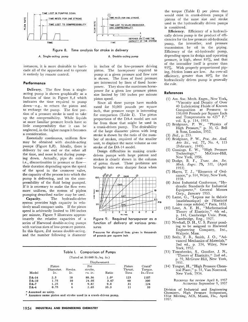
Capacity. The hydraulic-drive system provides high capacity in relatively small compact units. If the piston speed is arbitrarily limited to 180 inches per minute, Figure 9 illustrates approximately the relative capacities of a series of Harwood double-acting pumps with various sizes of low-pressure pistons. In this figure, DA means double-acting. and the number following is diameter
B. Double-acting pump
m inches of the low-pressure driving piston. The horsepower required to pump at a given pressure and flow rate is shown. The lines of fixed pressure are intersected by lines of fixed horsepower. They show the maximum horsepower for a given low pressure piston size limited by 180 inches per minute piston speed.
Since all these pumps have models rated for 50,000 pounds per square inch, that pressure range is interesting for comparison (Table I). The piston proportions of the DA-4 model are not far from those that might be used in a crank-driven pump. The desirability of the large diameter piston with long stroke is shown by the ratio of the number of strokes, required of the smaller unit, to displace the same volume as one stroke of the DA-14 model.
Design difficulties in making crankdriven pumps with large pistons and strokes is clearly shown in the column of piston thrust. These problems are brought into even sharper focus when
0 100 '];" ~ ':5 DA14 'V
fl I I I/ l rm I 0~101 v I
' ~I
/ y 10
I I I v 1/
~v DA7 r:;; I
~ 60
I v 51 1/ ~ t..-1-- i="' I
-~ ;::::r I l 20
k
2 4 5 6 7 8 GAL/MIN.
Figure 9. Required horsepower as a function of delivery at various pressures
Pressures for diagonal lines given in thousands af pounds per square inch
Table I. Comparison of Pumps
(Tl.ated at 50.000 lb./sq. in.)
Displacement Piston Per Piston Crankb
Diameter, Stroke. stroke. Thrust. Torque, Model In. In. C'lt. in. Ratio Tons ln.-Tons
DA-14 2.5 18 88.36 1.0" 123 1107 DA-10 1. 75 10 24.05 3.67 60 300 DA-7 1.25 8 9.82 9.0 31 124 DA-4 0.75 6 2.65 33.3 11 33
" Assumed as unity. ~ Assumes same piston and stroke used in a crank-driven pump.
1954 INDUSTRIAL AND ENGINEERING CHEMISTRY
PSI
the torque (Table I) per piston that would exist in crank-driven pumps if pistons of the same size and stroke used in the hydraulically driven pumps is considered.
Efficiency. Efficiency of a hydraulically driven pump is the product of efficiencies for the low pressure oil-hydraulic pump, the intensifier, and pressure transmiSSion by oil in the piping. Efficiency of the oil-hydraulic pump, depending upon its design and operating pressure, is high, about 85%, and that of the intensifier itself is greater than 95%. With properly proportioned piping, friction losses are low. An over-all efficiency, greater than 80% for the hydraulically driven pump is generally the rule.
References
(1)
(2)
(3) (4)
(5)
(6)
(7)
(8)
(9)
(10)
(11)
(12)
(13)
(14)
Am. Soc. Mech. Engrs., New York, "Viscosity and Density of Over 40 Lubricating Fluids of Known Composition at Pressures to 150 000 Pounds per Square Inch
' 5° F" and Temperatures to 42 . vol. 2, p. 114, 1953.
Bridgman, P. W., "Physics of High Pressure," p. 30, G. Bell & Sons, London, 1952.
Ibid., p. 233. Bridgman, P. W., Proc. Am. Acad.
Arts Sci., vol. 77, No. 4, 115 (February, 1949).
Comings, E. W., "High Pressure Technology," McGraw-Hill, New York, 1956.
Dodge, B. F., Trans. Am. Soc. Mech. Engrs. 75, 331, (April 1953).
Hayes, T. J., "Elements of Ordnance," p. 164, Wiley, New York, 1938.
Joint Industrial Conference, "Hydraulic Standards for Industrial Equipment," General Motors Corp., January 1953.
Lame, G., "Lec;ons sur la theorie (mathematique) de l'elasticite (des corps solides)," Paris, 1852.
Love, A. E. H., "Mathematical Theory of Elasticity," 4th ed., p. 144, Cambridge Univ. Press, Cambridge, Eng., 1927.
Newhall, D. H., U. S. Patent pending to be assigned to Harwood Engineering Company, Inc., Walpole, Mass.
Seely, F. B., Smith, J. 0., "Advanced Mechanics of Materials," 2nd ed., p. 334, Wiley, New York, 1952.
Timoshenko, S., Goodier. J. N., "Theory of Elasticity," 2nd ed., p. 59, McGraw-Hill, New York, 1951.
Tongue, H., "High Pressure Chemical Plant," p. 51, Van Nostrand, New York, 1934.
RECEIVED for review April 8, 1957 AccEPTED September 9, 1957
Division of Industrial and Engineering Chemistry, High Pr<'ssure Symposium, 131st Meeting, ACS, Miami, Fla., April 1957.