hydraulics branch official file copy
TRANSCRIPT

PAP-515
HYDRAULICS BRANCH OFFICIAL FILE COPY
Hydraulic Design of Angled Drum Fish Screens
By
Perry L. Johnson
Presented at Electric Power Research Institute
Conference on Fish Protection at Steam and Hydro Power Plants
San Francisco, California
October 28-30, 1987

' -
')
ABSTRACT
HYDRAULIC DESIGN OF ANGLED DRUM FISH SCREENS
,/~try L. Johnson U. S. Bureau of Reclamation
Mail Code D-1531 PO Box 25007
Denver, Colorado 80225
Angled drum screens, a recent development in fish control structures, are best suited for open channel applications such as on flow diversion canals. The concept combines angled screen placement to the flow, which minimizes fish impingement and maximizes fish guidance, with drum screens, which are proven cost effective traveling screens. For optimum guidance the approach flow to the screens should be eddy and slack water free, the flow field through the screens should be unifonn and should comply with velocity criteria, and the flow into the bypass intakes should be uniform or gradually accelerating. Parameters influencing hydraulic performance include initial flow distribution, intake and exit channel geometry, intake and exit channel losses, head losses across the screens and screen structure, and geometric details of transitions, screen structure, and bypass intake. This paper presents hydraulic design guidelines that were developed through use of three site specific physical model studies and through use of a generalized hydraulic model study.
INTRODUCTION
- __ A- probl~m of current ~ctjve interest in both the hydropower and irrigation disciplines is fish exclusion. Passage of fish through turbines and diversion of fish into irrigation systems can result in substantial or total mortalities. Consequently, regulatory and fisheries agencies are insisting on the inclusion of effective fish passage and control facilities in new projects and the addition of effective facilities to projects that require relicensing .
The appropriate fish exclusion device or technique to be used is strongl y dependent on site specific factors such as structure type and configuration, fish species and development stage, operating seasons, debris types and load , and water quality. One type of structure that has been recently designed and constructed at several sites is the angled drum screen (fig. 1). This structure is best used at open channel flow sites. A typical installation would be on a power or irrigation canal downstream of the canal headworks. Flow with entrained fish is diverted into the canal. Through use of the angled drum screen the fish are removed from the diverted flow and returned to the initia l water body. Hopefully sufficient head is available to allow return of the fi s h by gra vity flow. The concept offers the combination of two proven elements. The fi rst is o 1 a cemen t of the screens at a s ii ght angle ( 1 ess than 25°) to the fl ow which creates hydrau l ic conditions that expedite gu i dance of fish to bypasses and that minimizes f~sh imc ingement. The second element i s us e of drum screens , wni ch are widely 1,; ;;ed an'.. proven mecnani cal screen , tha t have r e :: :i vel ~- : ow

Training wall
Guidewoll ~/ ~-i , ·,
Angle of structure
I Canal Flow
To river t PLAN
.. -- .. ........ , - : •. •,'/1
SECTION
. '-
t--.--Pier
ypass conduit
. ' ........ -
Figure 1. - Typical angled drum screen.
. \

..
_-·---
associated capital and operating costs as compared to traveling screens, that have a history of low maintenance, and that have good debris handling and cleaning characteristics.
Regulatory and fisheries agencies may require use of physical hydraulic models to confirm hydraulic flow characteristics, particularly for major new designs. Physical models can be used to confirm and adjust large scale flow patterns and to refine localized structural and flow details. Costs of physical model studies are often more than offset by savings realized due to improved designs. For smaller structures, howevar·,-t the time and cost associated with a physical model study may not be justifiable. Presented in this paper are hydraulic design guidelines. Items discussed include the influence of the angle at which the screen is set to the flow, the influence of intermediate pier size and spacing, the influence of loses through the drum screens and thus the influence of screen fabric, the influence of structure related losses, the influence of approach and exit channel cross-sectional area, the influence of approach flow distribution, and considerations in the design of structural details and channel transitions. The ·information presented results from three site specific physical model studies and from brief generalized studies that were done in conjunction with the site specific studies. It is intended that this paper supply sufficient information to al[ow design of a reasonably well performing structure. If an optimized design is needed, use of a physical model study would be required.
DESCRIPTION OF STRUCTURE
An angled drum screen structure consists of drum screens set end to end between piers (fig. 1). The front face of the piers is shaped to conform to the drums which minimizes blockage of fish movement as the fish are guided along the screens. The individual drums consist of rigid cylindrical frames covered by woven screen. The allowable size of openings in the screen depends on the size of fish and the screen fabric criteria of the regulatory agencies [typically 3 to 6 mesh with 0.10- to 0.25-in (2.5- to 6.4-rmn) openings]. Rubber seals that seat against the piers are attached to both ends of the drums. A bottom seal is fixed to the structure beneath the drum and sea ts against the drum surface. The drums rotate about their axis with a maximum outer circumference rotational speed of 10 ft/min (3.0 m/min). Typically the drums are chain driven
- from electric motors - located on top of the piers. The drums rotate such that the front (upstream) face rises and the back face descends. The drums are typically operated 0.7 to 0.8 submerged. Debris that impinges on the screen is carried over the top by the rota ti on and washed off the back by the through f1 ow. If the submergence drops much be 1 ow O. 7, debris tends to not cling to and carry over the drum but instead accumulates along the front face. Sprays and brushes have been used to improve cleaning. Drums have been constructed ranging from a few feet to 20 feet ( 6 .1 m) in diameter and from the typical 10 to 12 feet (3.0 to 3.7 m) up to 25 to 30 feet (7.6 to 9.1 m) in length.
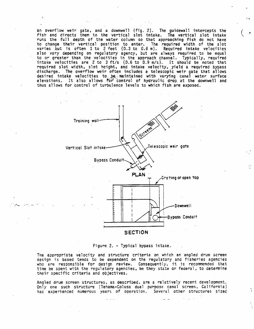
Positioned at the terminal end of the structure and at intermediate positions within tne structure (depending on the structure length and the flow velocity field) are bypass intakes (fig. 2). W. S. Rainey (7) presents a thorough discussion of the design of bypass systems. Bypass intakes function as velocity traps, intercepting and capturing the fish as they move along the screens and directing them tow a rd a pipe system which returns them to the waterway from which they came. The spacing between bypass intakes is dictated by the fish species and develooment state (swimming strength ) , the magnitude of the velocity components, and the time required for a fish to be guided down a length of screens and into a bypass intake. Typical spacing between bypass intakes is 100 to 125 feet ( 30 .5 to 38. : m) . The bypass intake includes a guidewall , a vertical slot intake,
---
an overflow weir gate. and a down we 11 (fig. 2). The gui dewa 11 intercepts the fish and directs them to the vertical slot intake. The vertical slot intake runs the full depth of the water column so that approaching fish do not have to change their vertical position to enter. The required width of the slot varies but is often 1 to 2 feet (0.3 to 0.6 m). Required intake velocities also vary depending on regulatory agency, but are always required to be equal to or greater than the velocities in the approach channel. Typically, required intake velocities are 2 to 3 ft/s (0.6 to 0.9 m/s). It should be noted that required slot width, slot height, and intake velocity, yield a required bypass discharge. The overflow weir often includes a telescopic weir gate that allows desired intake velocities to . J.>~ . maintained with varying canal water surface elevations. It also allows tof control of hydraulic drop. at the downwell and thus allows for control of turbulence levels to which fish are exposed.
Training wall
Vertical Slot Intake gate
Bypass Conduit
Grating or open top
Oownwell
SECTION
Figure 2. - Typical bypass intake.
The appropriate velocity and structure criteria on which an angled drum screen design is based tends to be dependent on the regulatory and fisheries agencies who are responsible for design review. Consequently, it is recommended that time be spent with the regulatory agencies, be they state or federal, to determine their specific criteria and objectives.
Angled drum screen structures, as described, are a relatively recent development. Onl y one such structure (Tehama-Colusa dual purpose canal screen, Californ ia) has expe r ienced numerous years of operation. Severa l other structures sized
..
( .

to screen discharges ranging from 100 to 3,200 ft/s (2.8 to 90.6 m3/s) are in various phases of design, construction, or early operation. Limited field evaluations have been conducted at the Sunnyside (6) and Wapato screens, Washington. At both sites the structures have proven effective in guidance and bypass of the target fish (fingerling steelhead and salmon).
HYDRAULIC OBJECTIVES
The approach channel to the screens should be designed to mrn1m1ze slack water areas and back eddies. Predatory fish can hold in these areas with low energy expenditure and feed on the target fish. tlimination of slack water areas also a 11 ows for more direct movement of the fish to the screens and then on to the bypasses. Elimination of slack water and eddies basically requires that transitions be sufficiently long to prevent flow separation or significant reduction in boundary velocities. Likewise, any appurtenances to the structure, such as the bypass intake guidewalls, should be correctly aligned and shaped to minimize flow separation.
Beyond this the objective is to maintain approach velocities that are of equal or somewhat smaller magnitude than the velocities in the vertical slot of the bypass intake and to create a uniform flow field over the length of the structure that will minimize impingement of fish against the screens and maximize guidance of fish to the bypass intakes. To minimize impingement it is required that the component of the approach ve 1 oci ty norma 1 to the screen be sma 11, often 0.5 ft/s (0.15 m/s) or less at the maximum discharge. io maximize guidance it is typically required that the component of the approach velocity parallel to the screens have a magnitude that is equal to at least twice the magnitude of the norma 1 component. io a chi eve these objectives requires that both the magnitude and the angle of attack of the approach velocity be within set limits. For the parallel component to have at least twice the magnitude of the normal component the angle of attack of the approach flow to the screens must be 26.5° or 1 ess. The magnitude of the norma 1 component is equa 1 to the sine of the angle of attack times the magnitude of the approach velocity. For the magnitude of the normal component - to be 0.5 ft/s (0.15m/s) the angle of attack must be 29.5° if the magnitude of the approach flow is 1.0 ft/s (0.30 m/s), 14.5° if
- - -- - the magnitude of the a·pproach flow is · 2.0 ft/s (0.61 m/s), and 9.6° if the magnitude of the approach flow is 3.0 ft/s (0.91 m/s).
It has been observed that the screen structure and in particular the piers intercept the flow, turning a portion of the flow through the structure and deflecting a portion of the flow downstream at a reduced angle. Consequently over the bulk of the structure the angle of attack will be something less than the angle at which the structure sits across the channel. For example at one site the structure was placed at an angle of 17.5° to the channel but the resulting a~gle of flow attack was approximately 12° over the bulk of the structure. At another site the structure was set at an angle of 15° to the channel. Resulting angles of attack were, however, approximately 10°. At a third site the structure was set at an angle of 21.33° and resulting angle of attack was approximately 16°. Thus, it appears that for typical structures, deflection of the approach fl ow results in approximately a 5° to 6° reduction in the angle of attack. An exception occu-rs at the first few drums where the structure has not deflected the flow and consequently where the angle of flow attack is equal to the angie at whic h the structure is set. Consequentl y , the normal components at the first few drums may exceed criteria while the normul velocity components over the bu lk of the structure are in compliance. Three options are available to reduce normal component maani tudes at the first screens. The structure ma,, ne real i oned at c. flatter angl e~ t nr cross section Of -~ne approach channe l ma.\ De enlarged

and thus the magnitude of the approach velocities reduced, or the flow approaching ( . • the first drum could be deflected to both reduce the angle of attack or reduce local velocity magnitudes.
Another hydraulic concern is sedimentation. Often construction of an angled drum screen requires enlargement of the channel cross section. This results in reduced velocities and reduced sediment carrying capacity. Consequently sedimentation in the screen approach and exit channels is likely. In addition because the structure is designed in compliance with the normal component criteria, average velocities through the screens and inmediately behind the screens will be equal to or J ,e.s·s: than the maximum allowable normal component. This is a low velocity zone which is very prone to deposition. Sediment deposition can potentially modify flow patterns through the screens and result in abrasion of screens and seals. Removal of deposition also represents a constant maintenance demand. To minimize deposition, entrance and exit channel velocities should be held as high as possible. To reduce deposition immediately behind the drum screens, stoplogs could be used to reduce the flow area and create a sluicing action. Use of uniform stoplogging over the length of the structure has little impact on approach flow distribution.
PARAMETER DISCUSSION
The following is a discussion of the parameters that influence the hydraulic performance of an angled drum screen structure.
Anole of Structure
In the generalized phase of this study a design was considered with the angle of the structure set at 22° and 0° (fig. 1). The cross section areas of the approach and exit channels were held constant as were the other geometric details of the structure. The angle was observed to have negligible influence on the resulting approach velocity distributions. As previously noted the one advantage of the 0° alignment is that the angle of flow attack on the first few drum screens is flat and consequently the normal and parallel velocity components will be in compliance. Beyond this, selection of the angle of structure set is largely dependent on site spectfic geometri-c details and use of an angle that minimizes structure complexity an~ cost.
Pier Lenoth and Soacing
Beyond screen support, the piers function as vanes or louvers intercepting and turning a portion of the flow through the structure while deflecting a portion of the flow down the approach channel. The piers are sources of flow separation, flow concentration, momentum change, and head loss. These effects are maximized due to the sharp angle of pier placement to the flow.
To evaluate the influence of pier length and spacing two structures were studied. One had piers with a length equal to two drum screen diameters positioned with a clear space between piers equal to 0.67 drum diameters. The other structure had piers with a length equal to one drum diameter positioned with a clear space between piers equal to 1.4 drum diameters. This represents probable extremes in pier size and spacing for large diameter drum screen structures. Both structures studied were 30 drum diameters long and were set at an angle of 22°. Approach and exit channel cross sections and a 11 other geometric deta i1 s were the same f or both cases. The two cases were studied at maximum discharge with average velocities in the approach channel of from 2 to 3 ft / s (0.6 to 0.9 m/ s). The longer more closely spaced piers caused a progressive increase in approach velocity as the flow passed down the structure length. Approach velocities

.. \
_----
at the start of the structure were not influenced (and thus were the same for both cases) but velocities 80 percent of the way down the structure were approximately 10 percent greater with the longer and closer spaced piers. At least a portion of this increase may be due to loss of screen area resulting from use of additional piers. From these data it was concluded that for the possible angles of structure set (0° to 26.5°), pier length and spacing has only secondary influence on resulting approach velocity distributions.
Discharge
The discharge equation:
Q = AV
where Q = volume discharge A= cross-sectional area V = mean velocity
can be used to size the approach channe 1 . Fl ow down the approach channe 1 is one directional and relatively parallel to the channel banks (or normal to the channel cross sections) which allows for direct application of the discharge equation. In addition, velocities down the length of the approach channel can be selected to reflect the desired velocity distributi-on and corresponding discharges and channel cross sections computed.
Findings indicate that this is a valid approach. The findings, however, show that the confiouration of the exit channel also influences the flow distribution in the approach channe 1. Direct sizing of the exit channe 1 through use of the discharge equation is less straight forward. The flow exits the screen structure parallel to the piers or perpendicular to the exit channel. The flow crosses the channel while turning to a down channel alignment. The result is a concentrated down channel flow in the outer one-third to one-half of the exit channel. Lancaster and Rhone (5) found that, depending on exit channel cross section and orientation, a substantial backwater buildup may be required to turn the flow in the exH channel. -They show that this can result in increased head loss across the structure and modification of approach flow distribution.
- - In attempting to apply - the discharge equation to sizing of the exit channel one must recognize the flow pattern and oversize the exit channel to compensate. It is recommended that the exit channel be at least half again wider than what is indicated by direct application of the discharge equation. The model studies indicate that the exit channel may be further oversized with little resulting influence on the approach channel velocity distribution. As an option to oversizing Lancaster and Rhone (5) show that flow straighteners, or walls placed parallel to the exit channel immediately behind the screen structure, may be used to turn the fl ow with reduced head 1 oss and a 11 ow use of an exit channe 1 sized directly by the discharge equation.
Screen Fabric
It was observed that energy, or the energy gradient field around and through the screen structure, likely has a significant influence on velocity distribution in the approach channe 1. A source of energy 1 oss through the structure results due to fl ow through the screen fabric of the drums. As previous 1 y noted, 3- to 6-mesh (openings per inch) screen with 30 to 50 percent open area is often used. Usually there is flow through both the front and back surfaces of the drum. In some designs onl y the front half of the drum seats against the piers in which case a po:-tion of the exiting flow passes out of the ooen sides of the drums.

In either case the screen fabric yields constriction of the flow path with localized acceleration and head loss. Studies done by Armour and Cannon (1) and confirmed by the TVA (Tennessee Valley Authority) (3) can be used to evaluate head losses associated with flow through screens. Armour and Cannon (1) indicate that:
where K = £ = d = a = m =
l i = =
l = R =
= V = u =
K = _l_ (103.4 (da)2) +
3£2 R 6.24 .£
l
pressure drop coefficjent = t.h/(V2/2g) screen void fractil:fh~e-, wire diameter area/volume ratio = 12/,r m2li mesh (openings per inch) length of a crimped wire (d2 + m-2)1/2
segment
width of hole in screen screen wire Reynolds number Vd/u upstream flow velocity kinematic viscosity
These studies were conducted for a single flat plane screen - not a screen with a drum configuration. Limited studies reported by Bell (2) imply that losses associated with perpendicular flow through both faces of a drum screen would equal 1.7 times losses associated with perpendicular flow through a single flat plane screen. These studies also indicate that for a drum screen with fabric that has 63.3 percent open area (the screen mesh was not given) the head loss (H1) with flow through both faces of the screen is:
v2 H1 = 2 9 . 2g
The TVA report ( 3), notes that for situations where the ang 1 e of attack of the flow on the screen is other than 90° the head loss can be estimated using the normal component of the velocity for "V" in the equations above. This being the case, and because -of the flat - angle of attack, losses due solely to flow passage through the drums wi 11 amount to 10 to 50 percent of the approach fl ow velocity head. · This - does not include losses associated with the structure.
To evaluate the influence of the screen fabric on the approach velocity distribution a simplified hydraulic model was studied sequentially with 2-mesh, 18-mesh, 30-mesh, and 60-mesh flat screens installed in the drum screen bays. With consideration of scale Reynolds number effects these screens should yield losses that range from 10 percent to 400 percent of losses associated with a 2 ft/s (0.6 m/s) approach velocity on a 4-mesh, 33.6 percent open area drum screen. It was found that there was very little difference in approach channel velocity distributions for the four cases. Consequently it was concluded that screen fabric and its associated losses are not significant factors to be considered in structure design.
Eneray Gradient
Beyond losses due to screen fabric the fl ow experiences energy 1 osses due to boundary friction and due to flow through the piers of the structure. Friction losses can be evaluated through the use of a relationship such as the Chezy equation :
v = cJ;s
( \

---
where V = mean velocity in the cross section C = Chezy coefficient r = hydraulic radius= A/P A = cross-sectional flow area p = wetted perimeter s = energy slope
The Chezy coefficient can be evaluated either through the use of a modified Moody diagram that considers Reynolds number and relative boundary roughness (4) or through a relationship such,at:
c = L49 rl/6 n
which relates the Chezy coefficient to Mannings "n" for English units. For the approach channel with a selected approach velocity and with an estimated boundary roughness , energy slope and total friction head losses can be evaluated. Note that the channel cross section is reducing over the length of the structure which requires an integrated application of the Chezy equation. When such calculations were made for a 570-ft-long (174-m) structure which includes 32 18.75-ftdiameter (5.715-m-diameter) drums with a uniform approach velocity of 2 ft / s (0.6 m/ s) the resulting calculated loss over the length of the approach channel was 0.041 ft (0.0125 m) of water or approximately two-t~irds of a velocity head. It was also noted that half of this loss occurred over the last four to five drums where the approach channel cross section was small.
As previously noted flow patterns in the exit channel are more complex and thus not as well suited for analysis . However, since the exit channel is typically oversized and since the narrowest portions of the exit channel (behind the first few drums) tends to experience reduced velocities, it is felt that friction losses in the exit channel will be small and may typically be half or less of the losses experienced in the approach channel.
A fi na 1 source of energy 1 oss would be due to the structure i tse 1 f. The work of Lancaster and Rhone (SJ supplies iosight into these losses. This work studied angled louver fish screens which create in effect a reduced scale representation
- --0f- the fl ow patterns- through the pi er _structure of the angled drum screen. Lancaster and Rhone found that losses through the structure are a function of angle of structure placement, angle of pier placement to the flow, magnitude of approach velocity, and size and configuration of the exit channel. A modified presentation of the Lancaster and Rhone head loss data is presented in figure 3. In figure 3 note that for angles of structure placement less than 30 "' (without flow straighteners) the angle has no affect on associated head loss. This finding is somewhat confirmed by the previously mentioned observation that angle of structure placement, be it 0° or 22°, has no noticeable influence on approach channel velocity distribution. The angle of pier placement for drum screen structures is tied directly to the angle of structure p1acement. To maintain a smooth screen face for fish guidance the piers must be placed perpendicular to the structure alignment. With this being the case the angle of pier placement is equa l to 90"' minus the angle of flow attack (fig. 3). For example, with a 12° angle of attack the associated structure head loss would be 4.8 approach ve 1 oci t y heads. Note that these data were obtained in a constant cross section flume. Thus the loss reducing influence of an oversized exit channe l is not considered. Note , also presented on figure 3 is a curve that defines losse s tha t occur when flow straighteners are used. These values likel y correspond to losses associated with an oversized exi t channel . From figure 3 with a 1:: c angle of attack and flow straighteners the structure loss woul ~ be three veloc it!

_-
heads. At 0° the loss would be 3.8 velocity heads, and at 26.5° the loss would be 2.25 velocity heads.
6
... I .. >N
" .:
="" •
(~) ANGI..E OF 1..0UVER SL.AT WITH 1..INE OF FL.OW
Figure 3. - Head loss characteristics of louver structure.
In summary, with adequ-ately sized approach and exit channels, the loss across the str.ucture (~tructure plus screen loss) is a dominate factor. If the approach channel is sized based on the discharge equation and the exit channel oversized (or if flow straighteners are included), the energy characteristics of the design can be considered as a line loss between two uniform elevation reservoirs. This implies that if the loss characteristics along the screen structure are uniform then the approach flow distribution will also be uniform. The exception to this would be at localized transitions or disturbances such as at the first few drums and irranediately around the bypass intakes.
Transitions
Transitions and structural disturbances are sources of back eddies, slack water zones, and velocity concentrations. To minimize these adverse conditions it is recommended that transitions, in particular expansions in the approach channel, be as long as possible. For example at one site where the approach channel bottom width expanded from 50 to 100 ft ( 15 to 30 m) with a 10-ft ( 3. 0 m) fl ow depth and with average approach velocities transitioning from from 3.5 to 1.8 ft/s (1.1 to 0.55 m/s), a 300-ft-long (90-m-long) expansion yielded an adequate veloci ty distribution while an 80-ft-long (24-m-long) expansion did not .
Care should also be taken at the bypass intakes to achieve both a uniform or s lightl y accelerating approach flow to the bypass and an eddy-free flow on the
(
\

---
back side of the guidewall (fig. 4). The first requirement to achieve these objectives is to properly align the guidewall ·with the approach flow. Basically the guidewall should be set parallel to the flow or at the angle of flow attack. For example at one site the screen structure was set at an angle of 17.5° with the canal centerline, the angle of approach flow attack over the midportion of the structure was 12°, and consequently the bypass guidewall was set at an angle of 12° with the structure. If the guidewall is set at too large of an angle with the structure a separation or eddy zone will result on the back side of the wall and a flow deceleration will occur between the wall and the screens approaching the bypass intake. JhEf··eddy on the back of the wall not only supplies predator habitat but also, if large enough, will disturb flow patterns across the drum immediately downstream · from the bypass. The discharge between the gui dewa 11 and the screens is the sum of the 1 oca 1 discharge through the screens and the bypass flow. This discharge is fairly independent of guidewall position, consequently if the wall is set too far from the structure the resulting velocities are reduced.
lntormoa,o,0 Bypass
. Gu1oowa11
Figure 4. - Intermediate bypass design.
Care should be taken in the design of the transition from the intermediate bypass to the drum screen immediately following. The guidewall must be placed a sufficient distance away from the screen structure to meet minimum bypass intake width criteria. This distance plus the guidewall width results in the outer face of the guidewall being well out away from the screen structure. A transition is therefore required to bring the flow cleanly back to the screens. If too abrupt of a transition is used eddies that extend over much of the immediately following drum can result. The transition shown ·in figure 4 has proven to be a simple but effective design. An extended blank structure is placed between the bypass intake and the following drum. An appropriate length for this blank reach would be 10 to 12 feet (3.0 to 3.7 m) for a 2-ft/s (0.6 m/s) approach channel velocity. This blank reach allows sufficient length for the transition. The transition itself is typically a vertical face extension of the outer face of the guidewall. A small angle (5° to 10°) miter between the guidewall and the transition is included to reduce the transition length. The vertical face of the transition extends from the ouidewall to the drum. The intersection of tne vertical face and the cylindrfcal drum yields offsets from the flow at the bottom and surface. However, it has been concluded that the resulting eddies are no"c substantial and are a small price to pay for the simplified transition construction.

-----
Aooroach flow distribution
All of the information presented to this point assumes a uniform flow distribution in the canal as it approaches the screen structure. Approach flow concentrations or nonuniform 'distribution can greatly modify flow patterns at the screen structure. It can result in high velocity zones (hot spots) on the screens which can yield the impingement of fish. At one site an angled drum screen structure had to be positioned on a canal bend. Due to the flow concentrating effects of the bend in conjunction with an ineffective expansion design, a large back eddy resulted which craated· reverse flow through the first three drums of the 18-drum structure. Flow concentrations can result from many causes with the most common being ineffective transitions, poor alignment of flow control or fl ow i nfl uenci ng structures irmnedi ate ly upstream of the screen structure, and bends in the approach canal. Efforts have been made to correct poor approach flow distrjbution through use of flow resistance (stoplogging) selectively placed behind the drums. The author has found this to be an ineffective technique and suggests that efforts concentrate on improving the flow distribution well upstream of the structure. As a first option it is suggested that a straight, well aligned channel that is at least 80 hydraulic radii long be supplied upstream of the screen structure. For typical canal applications with velocities less than 3 ft/s (0.9 m/s) this should be a sufficient length to equalize the velocity distribution. When canal velocities are greater than 3 ft/s (0.9 m/s) additional length of well aligned approach channel may be required. If sufficient length cannot be supplied then care should be taken to design the approach and any structures it might contain to minimize flow concentrations. Headworks structures, inverted siphon exits, tunnel exits, or any other structure that strongly influences fl ow di stri buti on and direction should be carefully designed and aligned. Transitions should be of sufficient length to prevent separation or slack water zones. If good flow distribution and direction cannot be supplied, guide vanes, variably distributed upstream stoplogging. or other structures which force redistribution of the flow can be used to establish good initial approach flow conditions. It is difficult to be specific about such options because of the site specific nature of the problem. It is recommended that where such problems exist the use of a physical hydraulic model study be strongly considered.
-- SUMMARY. AND CONCLUSIONS -
Angled drum screen structures offer a state-of-the-art technique for excluding fish from canal flows. Currently numerous angled drum screen structures with hydraulic capacities ranging from 100 to 3,200 ft3/s (2.8 to 90.6 m3/s) are in design or construction. As of this writing three major structures have gone into operation and have proven effective in supplying mortality free fish guidance and bypass. Angled drum screen structures combine two proven elements: angled screen placement which creates flow patterns that guide the fish to the bypasses while minimizing fish impingement, and drum screens which are reiatively simple mechanical screens offering good cleaning and debris handling characteristics while being relatively inexpensive and maintenance free as compared to other traveling screen options.
The flow patterns approaching and through the screens are critical if optimum performance of the structures is to be obtained. The approach fl ow should be free of back eddies and slack water to eliminate zones where predator fish can hold and to optimize fish guidance and bypass. This requires that transitions and structure details be well aligned and hydraulically clean . Beyond this, tne approach flow to the screens should be uniform with magnitude and angle of approach such that the co::ioonent s of the ve 1 oci ty norma 1 to tne screens \Ji 11
..
( .

( be small, 0.5 ft/s (0.15 m/s) or less, and the components of the velocities parallel to the screens will be at least twice the magnitude of the normal components. The approach velocity should also be such that uniform or slightly accelerating flow to the bypass intake resu1ts. Specific velocity criteria is dependent on the regulatory agencies reviewing the design. Physical hydraulic model studies should be used to optimize and confirm the flow characteristics of a design. However, the information presented in this paper can be used to develop either initial designs or to develop designs of smaller structures that do not warrant a mode 1 study. ,;.."·,t :
Through the use of three physical model studies of specific structures and limited general study the design significance of various parameters was evaluated. It was conc1uded that the ang1e at which the screen structure is set (be it parallel to . the canal or at angles up to 26.5°), the length of and spacing between the drum screen supporting piers, and the screen fabric with its particu1ar mesh and percentage of open area have at most limited influence on approach velocity patterns and distribution. Consequently these parameters can be evaluated based on site and economic considerations and regulatory agency preference. The critical factor to be considered in the hydraulic desi9n of the structure, beyond supplying eddy free approach flow, is to supply adeq~ately sized approach and exit channels. The approach channel should be sized based on the discharge equation. Thus, desired approach velocity distributions can be selected and corresponding channel cross sections computed.
Beyond this the energy gradient approaching, through, and exiting the structure has major influence on the approach flow distribution. If properly sized, losses in the approach and exit channels are small. The dominate loss (2.25 to 4 approach flow velocity heads) occurs due to the screen structure. Consequently, the energy gradient can be described as a line loss between two fairly constant e1evation water bodies. Therefore, if losses along the length of the screen structure are constant, the resulting flow distribution will also be constant. With respect to sizing the exit channel, the flow exits the screen structure normal to the structure. Frequently this flow is also normal to the alignment of the exit channel. The flow crosses the exit channel gradually turning to a down channel direction. Studies - have shown that with smaller exit channel
_ cross sections subst~nti_al backwater is required to turn this flow. This backwater cin modify . the energy gradient acrois the screen structure and yield nonuniform approach flow distribution. To eliminate this problem the exit channel may be oversized (at least half again larger than indicated by direct application of the discharge equation), the exit channel may be realigned, or flow straightener vanes can be used to turn the fiow to a downstream direction.
Finally the initial flow distribution can significantly influence approach flow patterns. It is reco1T1T1ended that every effort be made to supply relatively uniform initial distribution. If because of upstream structure alignment or bends in the upstream channe 1 this cannot be done, it is recommended that a physical model study be used to develop satisfactory hydraulic conditions.
APPENDIX I.- REFERENCES
1. Armour, J. C. , and Cannon, J. N. , 11 F1 ui d Fl ow Through Woven Screens, 11 JA I CHE Vol. 14, No. 3, May 1968, pp. 415-420.
2. Bell, M. C., "Fisheries Handbook of Engineering Requirements and Biolooical Criteria, " U. S. Army Corps of Engineers, North Pa cific Division, February
· 1973.

3. "Flow Through Screens," Tennessee Valley Authority, Division of Water Management , Water Systems Development Branch, Report No. 87-8, May 1976.
4 . Henderson, F. M., Open Channel Flow, The MacMillan Company, New York, 1966.
5 . Lancaster, D. M., and Rhone, T. J., "Field and Laboratory Tests to Develop the Design of a Fi sh Screen Structure, De 1 ta-Mendota Cana 1 Headworks, Centra 1 Valley Project, California," U. S. Bureau of Reclamation, Hydraulic Laboratory Report HYD-401, March 21, 1955.
~~"~-t· .: 6. Neitzel, D. A., "A Fisheri•s Evaluation of the Sunnyside Canal Fish Screening Facility, Spring 1985," Batelle, Pacific NW Laboratory, December 1985.
7. Rainey, W. S., "Considerations in the Design of Juvenile Bypass Systems," Proceedings of the Symposium on Small Hydropower and Fisheries, The American Fisheries Society, May 1-3, 1985, pp. 261-268 .
' .
C
\ .