hydrogen explosions – an example of hazard avoidance and ... and loss...hydrogen explosions - an...
TRANSCRIPT
SYMPOSIUM SERIES No. 148 © 2001 IChemE
523
HYDROGEN EXPLOSIONS - AN EXAMPLE OF HAZARD AVOIDANCE AND CONTROL I.D. Kempsell, M.J. Wakem, M.P. Fairclough and J.M. Ingram* British Nuclear Fuels plc *Chemical Engineering Research Centre, South Bank Univ. London, SE1 0AA
Synopsis
Many nuclear chemical plants have to deal with hydrogen gas generation caused by reactions such as radiolysis of water. Because of the continuing major construction and decommissioning activities on the Sellafield site, guidance has been developed to build in safety as early as possible to ensure the safety of new plant and to continuously review existing plant. The guidance adopts the approach that prevention is better than complicated design. Therefore a hierarchy has been adopted that:
i) the design should be such that hazards are avoided
ii) the design should use passive features
iii) any failure or fault should produce no significant deviation
iv) the plant should be brought to a safe state by continuously available safety measures
v) administrative safety measures are an option only when there is no reasonable alternative
vi) finally mitigation is taken into account
The aim is to develop a design as close to the top of this list as possible, and to tailor assessment methods appropriate to the stage of design development. The application of these principles has been developed for the review of existing plant.
The guidance is supported by data and methods that may be required in making an assessment in detail (e.g. radiolysis generation rates, ventilation calculations, etc), and references further sources of information. Keywords: hydrogen, explosion prevention
BACKGROUND
Hydrogen generation, and hence the need to assess and control hydrogen explosions hazards is common to almost all nuclear chemical processing and many waste storage activities
When the phrase “Hydrogen explosion” is used in connection with the nuclear industry
peoples thoughts generally turn to well publicised incidents such as Three Mile Island or Chernobyl. At Three Mile Island an explosion of hydrogen, generated by the reaction of hot metal with steam, occurred during a severe loss of cooling accident in a nuclear reactor. This incident prompted a great deal of research into hydrogen explosions and models were developed to assist in severe accident analysis [1].
Although accidents such as TMI attract a lot of publicity, hydrogen is routinely
generated at nuclear installations by other mechanisms such as radiolysis, corrosion, chemical
SYMPOSIUM SERIES No. 148 © 2001 IChemE
524
degradation, and release from the disturbance of a bed of solids. It may also be used as a feed gas. Most of the above mechanisms for production of hydrogen are common to many industrial (and natural) processes. Radiolysis however is specific to the nuclear industry. Radiolytic hydrogen is encountered in a wide range of scenarios and is a potential hydrogen issue for many different processes and operations.
Incidents of hydrogen explosions
Given the extent of the potential for hydrogen generation at nuclear installations and in
particular reprocessing plant there appears to have been few reported incidents of hydrogen explosions in recent years. This would indicate that what incidents there have been must have been minor i.e. resulting in neither serious injury nor a significant release of activity and that, in general, hazards are being identified and controlled effectively. It is however interesting to note that a significant proportion of the incidents reported related to the unforeseen generation of hydrogen, in storage flasks/waste drums, such as illustrated by the case history below [2].
The incident, involving a transport cask, occurred at the Point Beach Nuclear Power
Plant on the 28th May 1996. A hydrogen explosion occurred during the welding of the shield lid on the multi-assembly sealed basket of a spent fuel storage cask. The root cause of the accident in this case was the failure of designers at several stages of the design process to identify a mechanism by which significant quantities of hydrogen could be produced within the flask. The process of transferring the spent fuel from the storage pond to the cask consisted of the following stages. The cask is first lowered into the spent fuel pool and loaded with spent fuel. It is then removed from the pool remaining mostly filled with pond water. The lid is then lowered into place and welded shut prior to the flask being drained of water, vacuum dried and filled with helium. An investigation into the root cause of the accident revealed that the hydrogen had been produced by an electrochemical reaction of the basket’s zinc containing coating with the borated fuel pond water. The delay between putting the lid in place and welding was sufficient for a flammable atmosphere to form in the cask. The explosion was sufficient to lift the lid by about 3 inches but there was no damage to the cask, injury to workers or release of activity as a result of the explosion.
In contrast, outside of the nuclear industry, many of the incidents reported relate to
explosive atmospheres formed by releases of large volumes of hydrogen from pressurised systems. An example of such an incident occurred at the Fuji Oil Sodegaura refinery, Japan in 1992 [3]. A large release of hydrogen occurred from a rupture on a feed/reactor effluent heat exchanger on the heavy oil indirect desulphurization unit as the plant was being started up after shutdown. After a few minutes, during which time personnel took measures to try and stop the leak, it exploded killing ten people and injuring seven. In this case the cause of the leak was traced back to a repair made to a gasket retainer on the heat exchanger. There have also been reported incidents of explosions inside vessels and pipelines. One such incident occurred in a pipeline for the transfer of CO2 from an ammonia plant [4]. The gas in the pipeline normally contained 2-3% hydrogen and a trip system was installed to shut down the transfer process if the concentration exceeded 8%. When the explosion occurred the plant had been down and the line out of operation for six days. The line had also been purged with nitrogen and blinded. From the damage it was estimated that the pipeline must have contained more than 10-15 % hydrogen and 40% air. The cause of failure of the trip system was clearly identified. The trip required signals from two hydrogen analysers, sent via a printer, and one of these had been disabled whist re-configuring one of the analysers/printer for the monitoring
SYMPOSIUM SERIES No. 148 © 2001 IChemE
525
of H2 in N2. It was not fully established why the nitrogen purge failed, how a sufficient volume of air to form an explosive mixture could have entered the pipeline or the exact source of ignition.
WHY IS THERE A NEED FOR GUIDANCE?
Hydrogen is a potential issue for many different types of plant and processes. All designers and assessors need to be able to identify that they have hydrogen issues, have guidance on how to assess the hazard, how to control it and know when to seek expert advice. In the past designers would have to seek information from a number of sources (e.g. radiolysis experts, corrosion experts, flammability experts etc.) in order to assess the hydrogen hazards and implement suitable explosion prevention and protection measures. There is considerable guidance in the literature on design for hydrogen issues, and although in BNFL and the nuclear industry in general there have been very few reported incidents in recent years involving hydrogen. It is however:
1. important to remain vigilant 2. desirable to minimise reliance on designers and experts 3. important that hydrogen control and good design should be built into the design
process as early as possible 4. important that decisions on hydrogen control should be integrated with other hazard
elimination or reduction decisions, and 5. advantageous to ‘demystify’ the majority of hydrogen issues, making better designs
more likely The development of guidance has been a considerable undertaking. The exercise began
by reviewing international standards and guides. There is a wealth of good literature spanning a large field including furnace design, ventilation design, explosion prevention and protection, overpressure calculations, explosion reliefs, etc. Given this background, it was decided to produce a ‘route map’ based guidance using basic principles to enable designers and reviewers of existing plants, to see the ‘wood from the trees’.
This led to the development of hydrogen guidance within BNFL.
THE PRINCIPLES
All new plant should be designed, in order of preference, according to the following principles.
1. As far as reasonably practicable avoid the generation/use of hydrogen. 2. (a) If hydrogen generation cannot be eliminated measures must be taken to prevent the
formation of flammable atmospheres. This can be achieved by various means
�� By control of the hydrogen concentration, or �� By control of the oxygen concentration, or �� By operation above the autoignition (AIT) temperature
SYMPOSIUM SERIES No. 148 © 2001 IChemE
526
2. (b) As a matter of good practice where there is potential for significant hydrogen
generation/release, irrespective of any explosion prevention measures, it is required (so far as it is reasonably practicable) that:
�� particularly if consequences of an explosion are high, vessels and pipework are
designed to withstand hydrogen explosions.
�� ignition sources should be eliminated. Credit should however not (or need to be) taken for such measures in the safety case. Safety cases requiring credit to be taken for such measures are unlikely to be acceptable (see point 5 below). Safety cases should be based on the prevention of the formation of flammable atmospheres.
3. In the event of fault conditions the design should be such that the deviation away from
normal operating conditions is slow and a flammable atmosphere is never formed.
(a) Ideally the plant design should aim to be deterministically safe i.e. it should be physically impossible for significant volumes of flammable atmosphere to form e.g. by use of natural ventilation.
(b) Only if a passive safety design is not possible should an active system be used to prevent flammable volumes forming.
4. Any design or process which gives a sudden release of a large volume of gas or allows
one to accumulate should be avoided if possible. 5. Plant designs relying on the low consequence of an explosion (e.g. explosion
containment) are generally unacceptable, as such an event is likely to be regarded as a loss of control of the process, and would lead to prolonged shutdown during investigation. For such a design to be acceptable it will be necessary to demonstrate why more preferred methods were not applicable.
In the case of existing plant the same principles should be applied if reasonably practicable. Nevertheless, there will be instances where this is not the case since the risk associated with modifying plant to fully meet the design principles could be greater than leaving it unchanged. In such cases modifications (if any) would be justified on a balance of risk.
The design principles and the acceptability of various methods for dealing with hydrogen
explosions can be seen more clearly on the ‘road maps’ discussed below.
DETAILED GUIDANCE The guidance is intended to ensure that the design principles are being applied
throughout the design process from the earliest stages i.e. from the concept stage studies right through to HAZOP of the final design. There were two important considerations during development:
SYMPOSIUM SERIES No. 148 © 2001 IChemE
527
�� The guidance should be comprehensive, covering as many scenarios where hydrogen hazards could arise as reasonably possible.
�� Give simple guidance in a format that design and safety engineers, without a great deal of specialist knowledge of hydrogen issues, could use safely. This should allow them to assess the hydrogen hazard and produce safety cases in straightforward commonly encountered scenarios but instructing them to seek guidance from specialists in cases that could present problematic/difficult hydrogen issues.
The development of the guidance required extensive input from people both from within
BNFL and externally across a range of disciplines with relevant experience/interests in hydrogen issues including inter alia CFD modellers, process engineers/designers, research scientists (e.g. corrosion experts, radiolysis experts), flammability & explosion experts. The finished guidance has also been reviewed by two external bodies. Fauske & Associates in the US, who have experience of hydrogen issues with similarities to those at Sellafied in US nuclear installations, and also the UK Health and Safety Laboratory, Buxton. The guidance is given in the form of annotated roadmaps.
Prior to considering the individual road maps it is worth considering some potential
means by which hydrogen may be generated which reflects the range of scenarios to which the guide is applicable.
Sources of hydrogen
The initial step in the design process is to identify and quantify all sources of hydrogen. Particularly at the conceptual stages consideration should be given to means by which it could be minimised or eliminated.
Radiolysis Radiolytic hydrogen is produced through the absorption of ionising radiation by a range
of materials. It may be encountered in connection with, for example, aqueous solutions containing radionuclides (with respect to re-processing the amount of hydrogen produced is often significantly reduced by the presence of high concentrations of nitrate ions), other hydrogen containing solutions (e.g. kerosene), contaminated materials such as plastics, radioactive waste encapsulated in concrete and fuel storage in ponds (i.e. radiolysis of water). The determination of the hydrogen generation rates for radiolysis is based on empirically derived G(H2) values which give the molecules of hydrogen produced per MeV of radiation absorbed for a specific material e.g. water and type of radiation e.g. �. It is usually possible to give bounding case values for G(H2) that can be used safely by non-experts.
Corrosion The other most commonly encountered mechanism for hydrogen generation at BNFL
installations is corrosion. Hydrogen from corrosion is less extensive in terms of the number of processes in which it occurs but is often more difficult to assess. The hydrogen generation rate can be affected by many factors such as the exposed surface area of metal (this will reduce significantly over time in the case of Magnox swarf in water), oxygenation of the solution,
SYMPOSIUM SERIES No. 148 © 2001 IChemE
528
and pH (high pH reduces Magnox corrosion rates). In addition in might be necessary to also consider the possibility of galvanic coupling. Other impurities, particularly chloride will also enhance corrosion rates. Hydrogen generated by corrosion is typically an issue for waste (e.g. Magnox cladding from decanning fuel) and fuel storage in silos/ponds. There is considerable amount of ongoing research being conducted by BNFL into hydrogen generation from corrosion to identify different cases rather than using a single worst case hydrogen generation rate.
Release from disturbance of sludges Where radioactive material is stored under water an amount of hydrogen (produced by
for example radiolysis or corrosion) will remain trapped within the sludge bed. If the material needs to be recovered from the tanks, disturbance of the bed will cause some of the trapped hydrogen to be released. This can present an additional problem for decommissioning operations since it can sometimes be difficult to predict the holdup and the amount that will be released and the rate of release during disturbance of the sludge bed. Such cases will invariably require input from experts in, for example, soil mechanics. As detailed on the flow sheets processes should be designed to gradually disturb such beds to release hydrogen in a controlled manner, or the vessel ullage should be inerted when it can be demonstrated that simultaneous oxygen and hydrogen generataion is negligible. Feed Material A third significant source of hydrogen is its use as feed material for certain reprocessing operations. Very few BNFL processes use significant quantities of hydrogen as a feed. Some use 100% hydrogen as a process material, but the majority use an ‘eversafe’ hydrogen-in-argon mixture. Reduction of water The application of water to esatablished fires involving reactive metals could potentially result in a hydrogen explosion. This is not an issue for normal plant operations but is a consideration for emergency fire fighting procedure/systems.
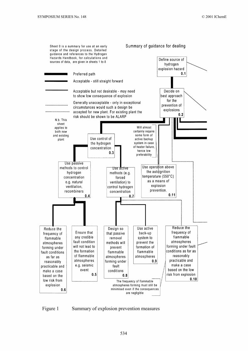
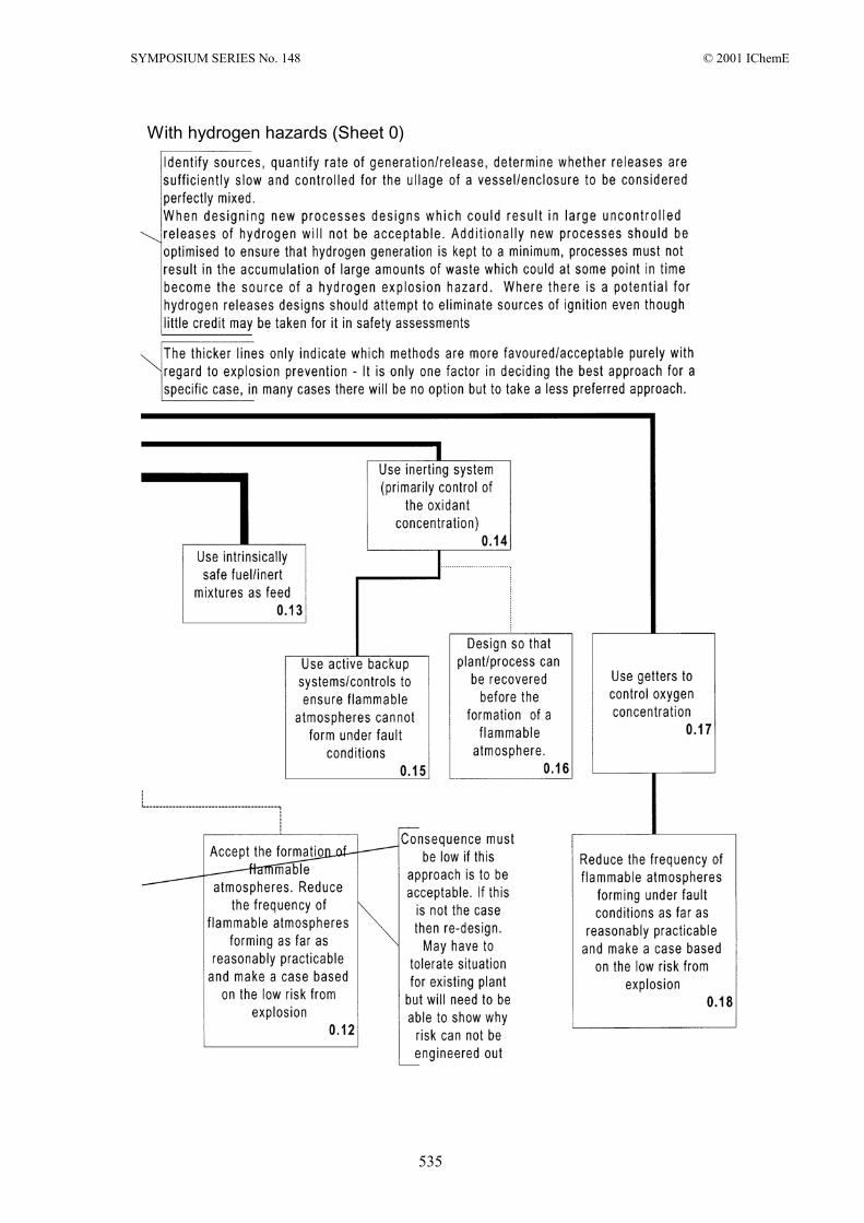
FIGURE 1 SUMMARY OF EXPLOSION PREVENTION MEASURES (SHEET 0)
Figure 1 would mainly be used at the early stages of the design process, such as concept development, process selection and early flowsheeting. The ability to control any hydrogen hazard needs to be evaluated when considering the various process designs options for new plant/processes. The ability to control the hydrogen hazard could determine whether a particular design is viable at all.
There are a number of methods for dealing with hydrogen hazards given on the
roadmaps. The most appropriate method is determined by too many different factors (not necessarily related to hydrogen hazards) to give definitive guidance on which is most applicable. It is however possible to offer guidance on how various options for the control of the hydrogen hazard relates to the hierarchy of the design principles as detailed above. This is the main function of Figure 1.
SYMPOSIUM SERIES No. 148 © 2001 IChemE
529
It can be seen that the boxes are joined by lines of different thickness. The thicker the
line connecting the final box the more preferred the solution with regard to the control of hydrogen hazards.
For example:
box 0.5 – preferred path-ideally plant should be deterministically safe box 0.10 – generally unacceptable – case based on low risk from explosion If a less preferred solution is to be adopted it will be necessary to demonstrate why a more preferred solution was not applicable. The numbering of the boxes is intended to be used to form an auditable trail of this decision process. The methods given on the roadmap for dealing with hydrogen hazards and their typical applications are described briefly below:
Control of the hydrogen concentration
In most cases explosions are prevented by maintaining sufficiently low hydrogen levels; <25% LFL for normal operation and <LFL under fault conditions (i.e. 1%(v/v) and 4%(v/v) at room temperature and pressure). This is normally accomplished for process vessels through forced ventilation, since natural ventilation or diffusion rates are often too small (especially to remain below 1%). In existing plant hydrogen is usually produced by mechanisms such as radiolysis of aqueous solutions and the release into the headspace of the vessel is slow and controlled. Existing process vessels typically have two independent air purges (from for example pneumercators which measure liquor levels by bubbling air into the vessels’ liquors) and the hydrogen concentration in the vessels can be estimated from the hydrogen generation rate and purge flows. Hydrogen detectors are rarely fitted to vessels used in these circumstances, to minimise the amount of equipment requiring maintenance in radioactive areas. Fault conditions are revealed by other means e.g. the detection of low flow purge air flows, high liquor levels (and hence increased hydrogen generation), etc. The combined flows from a group of process vessels often have on-line H2 measurement for reassurance. There is no need to specify limits for operation above the UFL since (for hydrogen) they are, in effect, defined by setting limits on the oxygen concentration as detailed below.
Although forced ventilation is the most common method by which hydrogen
concentrations are controlled, it is far from the only one. Other methods currently employed include:
Diffusion – Although diffusion is a slow process it can be a useful means of controlling
hydrogen concentrations in storage drums/ sealed flasks/ packages in which the hydrogen generation rate is sufficiently small. For example for low level waste storage in drums it may often be possible to keep the hydrogen concentration in the drum below 1%(v/v) by fitting a filter to the drum through which hydrogen could diffuse. Another example is the storage of plutonium contaminated material in sealed polyethylene film through which hydrogen can diffuse.
SYMPOSIUM SERIES No. 148 © 2001 IChemE
530
Recombiners - Essentially these are noble metal catalysts (usually palladium) which promote the low temperature recombination of hydrogen produced in the ullages of enclosures/vessels with oxygen to form water. Their use has so far been restricted to fuel transport/storage flasks.
Natural Ventilation - Where hydrogen is released slowly into buildings of normal
industrial design it may be possible to make a safety case based on generic data for the natural ventilation rates. In such cases a large safety margin would be applied to the predicted concentrations (i.e. an order of magnitude). It is however a useful as a tool for demonstrating that there is no credible explosion hazard in clear cut situations.
Buoyancy Driven Flow - Hydrogen is very much less dense than air and mixtures of
small amounts of hydrogen with air will be significantly less dense than air alone. If a vessel containing a hydrogen air mixture has, for example, two vertical pipes attached to the top of it (open to atmosphere) a buoyancy driven flow will be established. Fresh air will flow into the vessel down one pipe and hydrogen/air mixture out of the other the pressure driving the flow being related to the difference in density of the air and hydrogen/air mixture and the height of the outlet pipe. In some simple well defined situations this can be a good passive method of controlling the hydrogen concentration.
Use of intrinsically safe fuel inert mixtures as feed Although hydrogen issues are mainly associated with hydrogen produced as an unwanted
by product of radiolysis and corrosion it is used as a reducing atmosphere in certain nuclear chemical processing operations. For a given temperature/pressure there is a critical amount of hydrogen in a given inert gas below which a flammable atmosphere cannot form when mixed with air (i.e. the hydrogen inert mixture can be regarded as non-flammable provided its composition is reliable). This is obviously preferable to operating with a high concentration of hydrogen (above the UFL/below LOC) particularly as many BNFL processes operate at sub-atmospheric pressure.
Control of the oxidant concentration This is generally only considered where it is not possible to prevent explosions by
control of the hydrogen concentration. Given the choice between forced ventilation with air and inerting it will normally be cheaper and easier to opt for ventilation particularly as radiolysis will often generate oxygen as well as hydrogen. There are however several scenarios where keeping the atmosphere below the Limiting Oxygen Concentration (<2% (v/v) oxygen for normal operation (the LOC minus 3% (From NFPA 69)) and < 5%(v/v) under fault conditions) would be considered:
1. If the process requires high concentrations of hydrogen. 2. Where a large volume of hydrogen could be suddenly released (e.g. from disturbance
of sludge, and where the volume of oxygen co-released is negligible). 3. If the air ventilation rates required are particularly excessive. Even if hydrogen and
oxygen are being released in stoichiometric proportions the required ventilation rate using inert gas will be lower (half the generation rate and double the limit for normal
SYMPOSIUM SERIES No. 148 © 2001 IChemE
531
operation at RTP (2%(v/v)), and therefore has the potential benefit of lower activity discharges to air.
Another means of controlling the oxygen concentration is the use of getters. These are
essentially materials that slowly corrode and in doing so remove oxygen from the atmosphere. Their use, so far, has been restricted to fuel transport/storage flasks.
Operation above the Autoignition temperature There are a limited number of processes which need to operate above the autoignition
temperature (560°C). If this is the case it can be argued that the rate of oxidation will be sufficient to prevent a significant volume of pre-mixed flammable atmosphere from forming.
Low Risk from Explosion - Explosion Containment and Mitigation measures
For obvious reasons mitigation methods such as explosion venting, which would result in the release of material to the environment have always had extremely limited applicability to nuclear chemical processes. Less obvious is the restriction on the use of explosion containment. In principle explosion containment would be a valid means of controlling hydrogen explosion hazards. However in practice in order for a safety case based on explosion containment to be acceptable it is necessary to demonstrate that the vessel is not only designed to withstand the explosion now but is also designed to do so after, say 40 years of use. The undesirability of the use of explosion containment stems from both a requirement to prevent explosions in preference to minimising the consequences, as indicated by the design principles above, and the inevitable impracticalities of designing such vessels. In fact the majority of vessels constructed to BNFL standard pressure vessel design codes will withstand the deflagration of a stoichiometric hydrogen air mixture (initially at RTP).
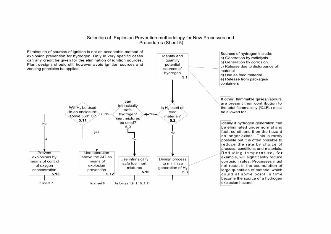
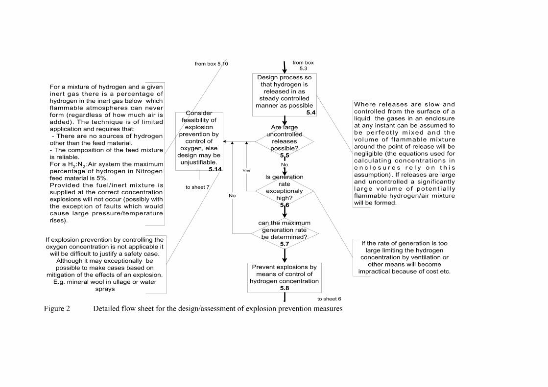
FIGURES 2,3 DETAILED FLOWSHEETS – DESIGN/ASSESSMENT OF EXPLOSION PREVENTION MEASURES (SHEETS 5 AND 6)
These are primarily intended for use at later stages of the design process. There is also an
additional set of similar flowsheets for the assessment of existing plant (i.e. for the production of Continued Operation Safety Reports). With existing plant the risk associated with modifying to meet the current explosion prevention standards could be greater than doing nothing i.e. a balance of risk argument would be permitted to justify not installing improvements, whereas new plant would need to meet current standards.
The flowsheets effectively set the explosion prevention standard. They would be used
initially in taking the chosen conceptual design through to the production of plant flow diagrams and revisited again during hazard assessments of the detailed engineering designs.
These flowsheets give a standardised process for assessing the adequacy of explosion
prevention measures. The required safety standards in terms of limits of hydrogen concentration etc. for safe operation under normal and fault conditions are built into the flow
SYMPOSIUM SERIES No. 148 © 2001 IChemE
532
sheets. The flow sheets incorporate detailed annotations and highlight many potential problems/pitfalls.
Again the boxes are numbered in order to facilitate the production of an auditable trail,
and the thicker lines indicate the preferred design which reflects the hierarchy of the design principles. For example, it can be seen how the design principles are incorporated into the road maps:
box 5.3 – requirement to minimise hydrogen generation. box 6.10 – it is better that a fault would never result in a flammable atmosphere rather
than making a case based on the fault being repaired in time. It should be noted that the flow sheets intentionally do not give guidance on the required
reliability of air purges etc as this is adequately covered by other BNFL standards/guidance.
General guidance
As mentioned in the design principles (and again on the road maps) there is a general requirement to eliminate, so far as is reasonably practicable, ignition sources wherever there is a potential for the release/generation of significant amounts of hydrogen. Credit should however not normally (or need to) be taken for such measures in safety assessments.
In the case of existing plant where it is necessary to take credit for the elimination of ignition sources to make a safety case, expert advice would have to be sought and the safety case will require technical peer review and a full audit trail of decisions.
Principal ignition sources include the following: Static sparks, sparks from electrical equipment, lightning, hot surfaces/particles (from frictional heating/impacts) and flames (e.g. from spontaneous ignition). With regard to nuclear chemical processing spontaneous ignition is known to be a potential problem with unusual chemicals such as uranium hydride, which can be generated in an atmosphere of damp hydrogen rich gas.
ASSESSMENT OF THE CONSEQUENCES OF EXPLOSIONS
The Guidance encourages explosion prevention. However, it is worth noting that he consequences of hydrogen within vessels/enclosures explosion would also normally be assessed to ensure compliance with quantified risk analysis techniques, as required by the Nuclear Installations Inspectorate.
CURRENT RESEARCH
BNFL is currently undertaking significant research for projects and for generic purposes. The principal generic research is in the following areas:
CFD modelling and validation programme and full size modelling of hydrogen dispersion in vessels from bubble release
�� Determination of likely overpressures during deflagration
Detonation/deflagration transition of confined hydrogen/air mixtures �� The geometry of containment may be critical in determining the transition from
deflagration to detonation. The safety issue is to determine the effect the geometry
SYMPOSIUM SERIES No. 148 © 2001 IChemE
533
of a containment may have on the transition from deflagration to detonation of an ignited hydrogen/air mixture
Hydrogen removal mechanisms
�� Safety can be improved if methods could be developed for the safe removal of hydrogen using Recombiners or Getters. The current strategy is to develop Recombiners (catalysts that recombine hydrogen and oxygen) as an alternative to Getters (materials which remove oxygen).
ADVANTAGES OF THE ROADMAP APPROACH
Producing the guidance in the form of road maps has a number of significant advantages. 1. Guidance presented in this form can be interpreted far more easily than written text. 2. At the concept stage of the design process adopting this approach encourages
designers to consider a range of solutions and not to opt for a particular path simply because that was how it was done last time.
3. Allows designers, without in depth knowledge of hydrogen issues, to identify hydrogen hazards and design in appropriate explosion prevention measures without recourse to experts in straightforward scenarios.
4. Provides a standardised framework for assessment of hydrogen hazards for a wide range of scenarios.
5. Numbered boxes simplify the production of an auditable trail of the decision process throughout all stages of the design/assessment.
6. The use of guidance in this way may be used as the basis for the development of an expert system.
REFERENCES 1. Lee J.H.S., Berman M., "Hydrogen Combustion and its Application to Nuclear Reactor
Safety", Adv Heat Transfer, 29 59 (1997). 2. NRC Report No. 50-266/301-96005, “Point Beach Augmented Inspection Team
Report”, 1996 3. The High Pressure Gas Safety Inst. of Japan, “The Fuji Oil Sodegaura Refinery
Accident”, Loss Prevention Bulletin (116), pp9-14, 1993 4. J.O. Pande, R.G. Stokke, J. Tonheim, “Explosion of Hydrogen in a Pipeline for CO2”,
Loss Prevention Bulletin (156), pp11-13, 2000
SYMPOSIUM SERIES No. 148 © 2001 IChemE
534
Figure 1 Summary of explosion prevention measures
SYMPOSIUM SERIES No. 148 © 2001 IChemE
535
With hydrogen hazards (Sheet 0)
Selection of Explosion Prevention methodology for New Processes andProcedures (Sheet 5)
Identify andquantifypotential
sources ofhydrogen
5.1
If other flammable gases/vapoursare present their contribution tothe total flammability (%LFL) mustbe allowed for.
Sources of hydrogen include:a) Generation by radiolysis.b) Generation by corrosion.c) Release due to disturbance ofmateriald) Use as feed material.e) Release from packages/containers
Design processto minimise
generation of H25.3
Is H2 used asfeed
material?5.2
Will H2 be usedin an enclosureabove 560° C?
5.11
Preventexplosions by
means of controlof oxygen
concentration5.13
Use operationabove the AIT as
means ofexplosionprevention
5.12
yes
No Ideally if hydrogen generation canbe eliminated under normal andfault conditions then the hazardno longer exists. This is rarelypossible but it is often possible toreduce the rate by choice ofprocess, conditions and materials.R e d u c i n g t e m p e r a tu r e , f o rexample, will significantly reducecorrosion rates. Processes mustnot result in the ccumulation oflarge quantities of material whichcou ld a t some po in t i n t imebecome the source of a hydrogenexplosion hazard.
canintrinsically
safehydrogen/
inert mixturesbe used?5.9
Use intrinsicallysafe fuel inert
mixtures5.10
to sheet 8
Elimination of sources of ignition is not an acceptable method ofexplosion prevention for hydrogen. Only in very specific casescan any credit be given for the elimination of ignition sources.Plant designs should still however avoid ignition sources andzoneing principles be applied.
No
As boxes 1.9, 1.10, 1.11
No
Yes
to sheet 7
Yes
Design process sothat hydrogen isreleased in as
steady controlledmanner as possible
5.4Where releases are slow andcontrolled from the surface of aliquid the gases in an enclosureat any instant can be assumed tobe pe r fec t l y m ixed and t hevolume of f lammable mixturearound the point of release will benegligible (the equations used forcalculat ing concentrat ions ine n c l o s u r e s r e l y o n t h i sassumption). If releases are largeand uncontrolled a significantlyla rge vo lume o f po ten t ia l l yflammable hydrogen/air mixturewill be formed.
Are largeuncontrolled
releasespossible?5.5
Prevent explosions bymeans of control of
hydrogen concentration5.8
Considerfeasibility ofexplosion
prevention bycontrol of
oxygen, elsedesign may beunjustifiable.
5.14
If explosion prevention by controlling theoxygen concentration is not applicable it
will be difficult to justify a safety case.Although it may exceptionally bepossible to make cases based on
mitigation of the effects of an explosion.E.g. mineral wool in ullage or water
sprays
to sheet 7
to sheet 6
If the rate of generation is toolarge limiting the hydrogen
concentration by ventilation orother means will become
impractical because of cost etc.
Is generationrate
exceptionalyhigh?5.6
Yes
can the maximumgeneration ratebe determined?
5.7
No
For a mixture of hydrogen and a giveninert gas there is a percentage ofhydrogen in the inert gas below whichflammable atmospheres can neverform (regardless of how much air isadded). The technique is of limitedapplication and requires that: - There are no sources of hydrogenother than the feed material.- The composition of the feed mixtureis reliable.For a H2:N2 :Air system the maximumpercentage of hydrogen in Nitrogenfeed material is 5%.Provided the fuel/ inert mixture issupplied at the correct concentrationexplosions will not occur (possibly withthe exception of faults which wouldcause large pressure/temperaturerises).
No
from box5.3
from box 5.10
Figure 2 Detailed flow sheet for the design/assessment of explosion prevention measures
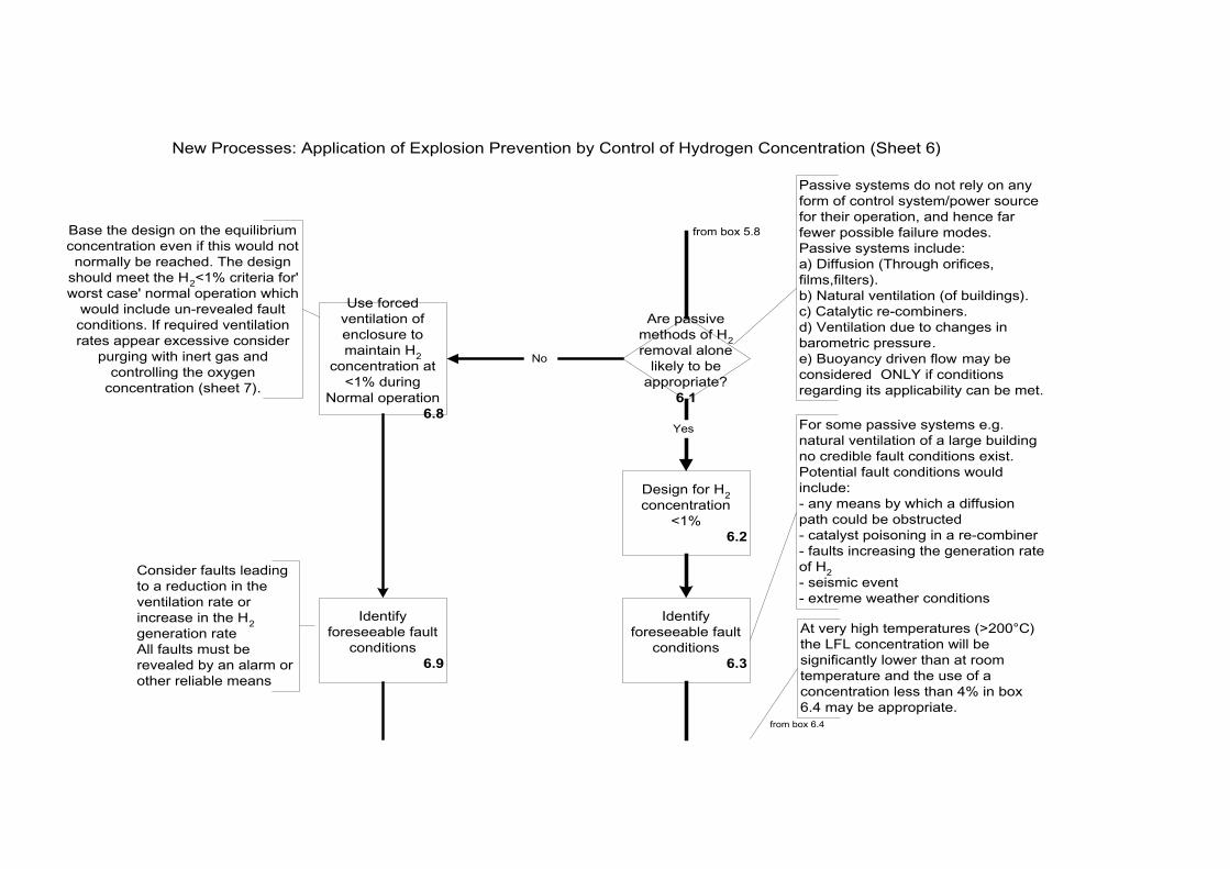
New Processes: Application of Explosion Prevention by Control of Hydrogen Concentration (Sheet 6)
Are passivemethods of H2removal alone
likely to beappropriate?
6.1
from box 5.8
Passive systems do not rely on anyform of control system/power sourcefor their operation, and hence farfewer possible failure modes.Passive systems include:a) Diffusion (Through orifices,films,filters).b) Natural ventilation (of buildings).c) Catalytic re-combiners.d) Ventilation due to changes inbarometric pressure.e) Buoyancy driven flow may beconsidered ONLY if conditionsregarding its applicability can be met.
Use forcedventilation ofenclosure tomaintain H2
concentration at<1% during
Normal operation6.8
Base the design on the equilibriumconcentration even if this would notnormally be reached. The design
should meet the H2<1% criteria for'worst case' normal operation which
would include un-revealed faultconditions. If required ventilationrates appear excessive consider
purging with inert gas andcontrolling the oxygen
concentration (sheet 7).
Identifyforeseeable fault
conditions6.9
Consider faults leadingto a reduction in theventilation rate orincrease in the H2generation rateAll faults must berevealed by an alarm orother reliable means
Design for H2concentration
<1%6.2
Identifyforeseeable fault
conditions6.3
For some passive systems e.g.natural ventilation of a large buildingno credible fault conditions exist.Potential fault conditions wouldinclude:- any means by which a diffusionpath could be obstructed- catalyst poisoning in a re-combiner- faults increasing the generation rateof H2- seismic event- extreme weather conditions
At very high temperatures (>200°C)the LFL concentration will besignificantly lower than at roomtemperature and the use of aconcentration less than 4% in box6.4 may be appropriate.
No
Yes
from box 6.4

will faultcondition result
in H2>4%?6.10
System must, if at allpossible, be designed so thatforeseeable faults conditionsdo not result in flammableatmospheres.
Credit may be given for anypurges not affected by thefault being considered andany passive removalmechanisms (noting thelimited applicability ofbuoyancy driven flowarguments)
Ideally the system should bedesigned so that passiveremoval mechanisms willmeet H2<4% in completeabsence of any forcedventilation
Is it crediblefault will not berevealed and
repaired beforeH2=4%?6.12
Yes
re-design system/alter process or
introduce back-upventilation to meet
at least Time to4%H2 > time for
revealed andrepaired or makea case based on
residual risk6.13
Yes
Designsatisfactory
6.11
Is it crediblefault will not berevealed and
repaired beforeH2=4%?6.6
Yes
No
re-design system/alter process or
introduce back-upventilation to meet
at least Time to4% H2 > time for
revealed andrepaired or makea case based on
residual risk6.7
Yes
will faultcondition result
in H2>4%?6.4
Designsatisfactory
6.5
No
No
No
from box 6.9
from box 6.3
Figure 3 Detailed flow sheet for the design/assessment of explosion prevention measures