hydromax system - centennial collegetransportation.centennialcollege.ca/athompson/reference...
TRANSCRIPT
HydroMaxHydroMax SystemSystem
In normal operation, fluid from the power In normal operation, fluid from the power steering pump enters the inlet port of the steering pump enters the inlet port of the HydroMaxHydroMax unit and flows through the unit and flows through the pressure valve, power piston and flow pressure valve, power piston and flow switch and exits from the return portswitch and exits from the return port

HydroMaxHydroMax SystemSystem

HydroMaxHydroMax SystemSystem
When force is applied to the brake pedal, When force is applied to the brake pedal, a pressure valve is activated which a pressure valve is activated which restricts the flow of fluid through the power restricts the flow of fluid through the power piston. The pressure then, acting on the piston. The pressure then, acting on the power piston applies a force to the master power piston applies a force to the master cylinder. The reaction piston provides the cylinder. The reaction piston provides the desired desired ““feelfeel”” at the brake pedal.at the brake pedal.
HydroMaxHydroMax SystemSystem
A pressure regulating device limits the A pressure regulating device limits the internal unit pressure developed during a internal unit pressure developed during a full braked application and retains full braked application and retains hydraulic pressure for steering.hydraulic pressure for steering.
HydroMaxHydroMax SystemSystem
The fluid flow switch is a The fluid flow switch is a ””openopen”” during during normal brake operation and a separate normal brake operation and a separate check valve in the motor pump prevents check valve in the motor pump prevents fluid from fluid from backflowingbackflowing through the pump.through the pump.

HydroMaxHydroMax SystemSystem
In the event of hydraulic pressure failure In the event of hydraulic pressure failure from the power steering pump, the flow from the power steering pump, the flow switch switch ““closescloses”” and the electric motor and the electric motor pump provides the hydraulic power pump provides the hydraulic power necessary to apply the brakes. The necessary to apply the brakes. The number of times the brakes can be applies number of times the brakes can be applies in the condition is limited only by the in the condition is limited only by the capacity of the vehicle's electrical system.capacity of the vehicle's electrical system.
HydroMaxHydroMax SystemSystem
The brakes can be applied The brakes can be applied manualymanualy if both if both the power (hydraulic) and reserve the power (hydraulic) and reserve (electrical) systems fail(electrical) systems fail
HydroMaxHydroMax SystemSystem
A A HydroMaxHydroMax hydraulic power brake hydraulic power brake system consists of:system consists of:A hydraulically powered boosterA hydraulically powered boosterA master cylinder A master cylinder As electric motor pumpAs electric motor pumpA warning systemA warning system

HydroMaxHydroMax SystemSystem
Power to the hydraulic booster for the Power to the hydraulic booster for the hydroMaxhydroMax system is provided by and system is provided by and engine driven hydraulic pump which engine driven hydraulic pump which boosts pressure to the master cylinder to boosts pressure to the master cylinder to increase brake system effectiveness.increase brake system effectiveness.

The Big PictureThe Big Picture

HydroMaxHydroMax AssemblyAssembly

HydroMaxHydroMax AssemblyAssembly
The area between the The area between the HydorMaxHydorMax booster booster pushrod forward Opushrod forward O--ring and the primary ring and the primary piston rear Opiston rear O--ring of the master cylinder is ring of the master cylinder is vented to the atmosphere. This venting vented to the atmosphere. This venting prevent mixture of the brake fluid with toe prevent mixture of the brake fluid with toe power steering fluid in the event one or power steering fluid in the event one or both of these oboth of these o--rings begins leaking.rings begins leaking.
Engine Running Engine Running ––No Brake No Brake ApplicationApplication
Engine Running Engine Running ––No Brake No Brake ApplicationApplication
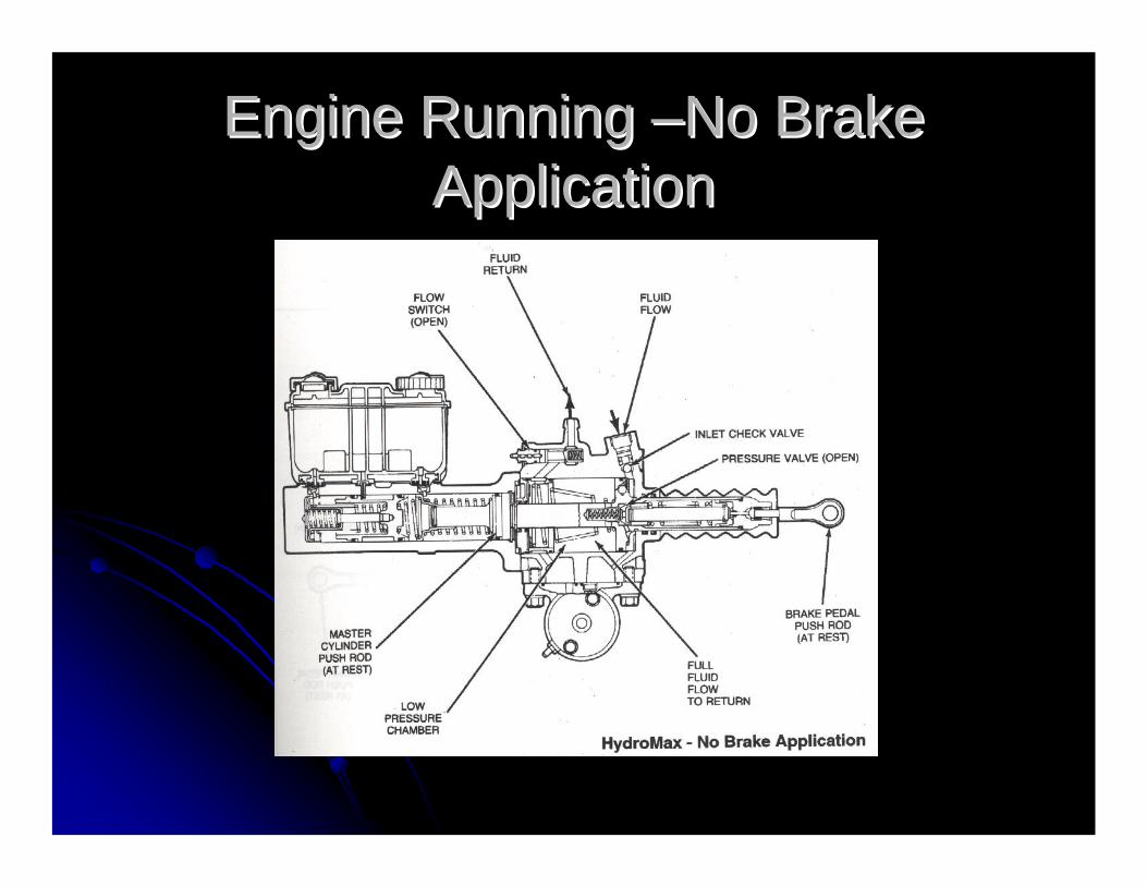
When the total system is functioning properly When the total system is functioning properly and the hydraulic pump is supplying the and the hydraulic pump is supplying the HydroMaxHydroMax unit, the flow through the unit is as unit, the flow through the unit is as shown.shown.1. Flow pressure from the power steering pump 1. Flow pressure from the power steering pump holds the holds the HydroMaxHydroMax booster inlet check valve booster inlet check valve openopen2. Before the brake pedal is applied, fluid passes 2. Before the brake pedal is applied, fluid passes freely through the pressure valve and into the freely through the pressure valve and into the low pressure chamber. low pressure chamber.

Engine Running Engine Running ––No Brake No Brake ApplicationApplication
3. Fluid passing out of the unit holds the 3. Fluid passing out of the unit holds the flow switch open, preventing operation of flow switch open, preventing operation of the electric motor pump.the electric motor pump.4. no pressure is applied to the power 4. no pressure is applied to the power piston and the master cylinder pushrod is piston and the master cylinder pushrod is at rest.at rest.5. No action takes place in the master 5. No action takes place in the master cylinder and no brake application is cylinder and no brake application is experienced. experienced.

Engine RunningEngine Running--Light Brake Light Brake ApplicationApplication

Engine RunningEngine Running--Light Brake Light Brake ApplicationApplication
As shown, the brake pedal has been depressed As shown, the brake pedal has been depressed slightly. This begins the power assist action of slightly. This begins the power assist action of the the HydroMaxHydroMax unit.unit.1. Flow pressure from the power steering pump 1. Flow pressure from the power steering pump holds the booster inlet check valve open.holds the booster inlet check valve open.2. The brake pedal push rod begins to close the 2. The brake pedal push rod begins to close the pressure valve. As the flow is restricted pressure pressure valve. As the flow is restricted pressure buildsbuilds--up in the high pressure chamber. The up in the high pressure chamber. The power piston is pushed by builtpower piston is pushed by built--up of pressure up of pressure and results in power boosted movement of the and results in power boosted movement of the master cylinder through the master cylinder master cylinder through the master cylinder push rodpush rod
Engine RunningEngine Running--Light Brake Light Brake ApplicationApplication
3. fluid passing out of the unit holds the flow 3. fluid passing out of the unit holds the flow switch open, preventing operation of the electric switch open, preventing operation of the electric motor pump.motor pump.4. The forward movement of the master cylinder 4. The forward movement of the master cylinder push rod forces the primary piston and actuator push rod forces the primary piston and actuator away from its compensating valve.away from its compensating valve.5. Hydraulic pressure builds in the primary 5. Hydraulic pressure builds in the primary braking system and primary brakes are applied.braking system and primary brakes are applied.
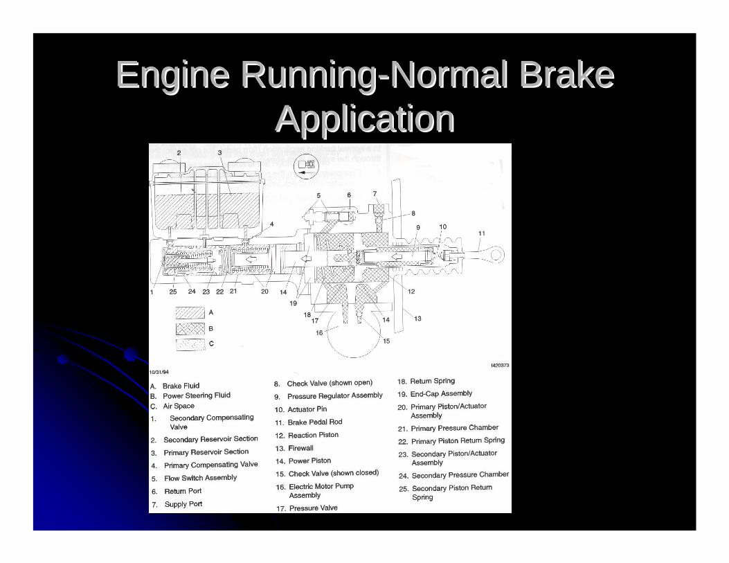
Engine RunningEngine Running--Normal Brake Normal Brake ApplicationApplication
Engine RunningEngine Running--Normal Brake Normal Brake ApplicationApplication
In a normal braking application (firm pedal, In a normal braking application (firm pedal, but not panic) the flow through the but not panic) the flow through the systesyste is is as followsas follows1. Flow pressure from the power steering 1. Flow pressure from the power steering pump holds the booster inlet check valve pump holds the booster inlet check valve open.open.2. Brake pedal push roe moves inward 2. Brake pedal push roe moves inward and he pressure valve partially closesand he pressure valve partially closes
Engine RunningEngine Running--Normal Brake Normal Brake ApplicationApplication
3. Pressure to the power piston is high.3. Pressure to the power piston is high.4. The master cylinder push rod moves further 4. The master cylinder push rod moves further into the master cylinderinto the master cylinder5. Fluid passing out of the unit holds the flow 5. Fluid passing out of the unit holds the flow switch open at the electric pump.switch open at the electric pump.6. Both the primary and secondary actuator 6. Both the primary and secondary actuator pistons are moved past the respective pistons are moved past the respective compensating valve and both the secondary and compensating valve and both the secondary and primary systems are pressurized. primary systems are pressurized.

Engine RunningEngine Running--Maximum Brake Maximum Brake ApplicationApplication

Engine RunningEngine Running--Maximum Brake Maximum Brake ApplicationApplication
Maximum application of the brake pedal, as may Maximum application of the brake pedal, as may be experienced during and emergency stop.be experienced during and emergency stop.1. Flow pressure holds the inlet check valve 1. Flow pressure holds the inlet check valve open.open.2. The brake pedal push rod moves inward, 2. The brake pedal push rod moves inward, virtually closing off fluid flow through the virtually closing off fluid flow through the pressure valve. This results in maximum rated pressure valve. This results in maximum rated pressure on the power piston, which is pressure on the power piston, which is transferred to the master cylinder through the transferred to the master cylinder through the master cylinder push rod.master cylinder push rod.
Engine RunningEngine Running--Maximum Brake Maximum Brake ApplicationApplication
3. The pressure regulator spring 3. The pressure regulator spring compresses and allows the pressure compresses and allows the pressure vlavevlaveto open slightly and bypass fluid through to open slightly and bypass fluid through the pressure valve orifice when maximum the pressure valve orifice when maximum preset pressure is exceeded.preset pressure is exceeded.4. Fluid passing out of the unit holds the 4. Fluid passing out of the unit holds the flow switch open, preventing operation of flow switch open, preventing operation of the electric motor pump.the electric motor pump.
Engine RunningEngine Running--Maximum Brake Maximum Brake ApplicationApplication
5. Both the primary and secondary actuator 5. Both the primary and secondary actuator pistons are moved to the maximum braking pistons are moved to the maximum braking position.position.6. If the combined demand of the power steering 6. If the combined demand of the power steering gear and the gear and the HydroMaxHydroMax unit should exceed the unit should exceed the capacity of the hydraulic pump to maintain capacity of the hydraulic pump to maintain adequate flow, the flow switch will close and the adequate flow, the flow switch will close and the electric motor pump will provide auxiliary fluid electric motor pump will provide auxiliary fluid pressure. pressure.
Engine RunningEngine Running--Maximum Brake Maximum Brake ApplicationApplication
In some applications the BRK ELEC MTR In some applications the BRK ELEC MTR lamp will illuminate and the buzzer will lamp will illuminate and the buzzer will sound for the period that the electric motor sound for the period that the electric motor pump is operating, This will only be a pump is operating, This will only be a momentary period when hard turning momentary period when hard turning (steering) and hard braking occur (steering) and hard braking occur simultaneously. simultaneously.
Hydraulic Booster MalfunctionHydraulic Booster Malfunction--Normal Brake ApplicationNormal Brake Application
Hydraulic Booster MalfunctionHydraulic Booster Malfunction--Normal Brake ApplicationNormal Brake Application
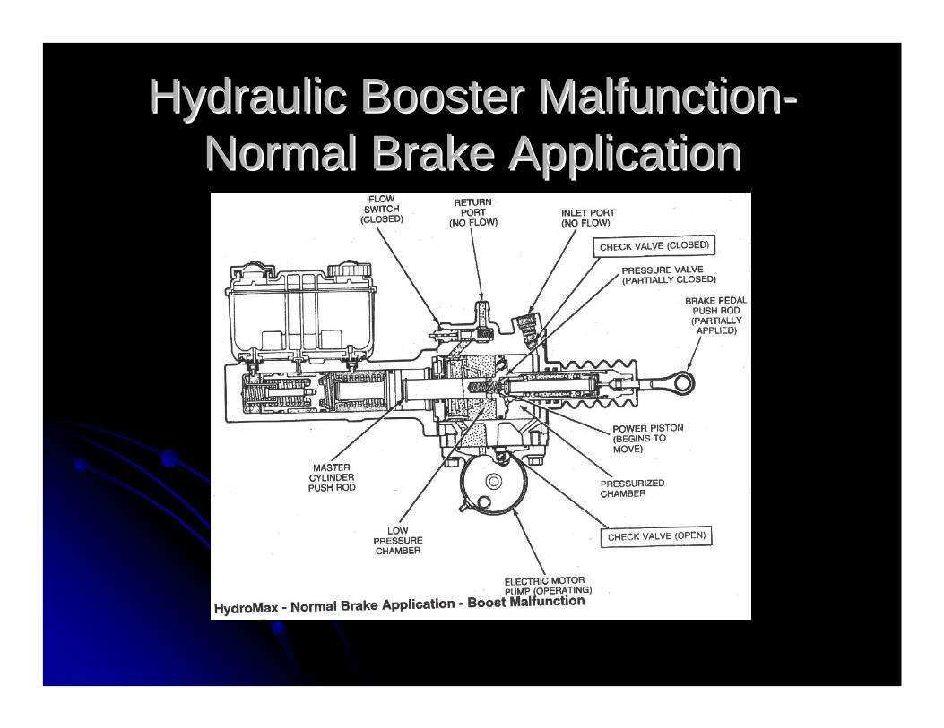
When brake boost is demanded and there When brake boost is demanded and there is no fluid flow to the is no fluid flow to the HydorMaxHydorMax Booster Booster unit because the engine is not running or unit because the engine is not running or some other condition has occurred to some other condition has occurred to interrupt fluid flow; the actuation of the unit interrupt fluid flow; the actuation of the unit is like this.is like this.1. The inlet check valve closes as a result 1. The inlet check valve closes as a result of no fluid flow entering the unit.of no fluid flow entering the unit.

Hydraulic Booster MalfunctionHydraulic Booster Malfunction--Normal Brake ApplicationNormal Brake Application
2. The flow switch closes since there is no flow 2. The flow switch closes since there is no flow to keep it open. This completes the electric to keep it open. This completes the electric circuit to the electric motor pump. Mounted to circuit to the electric motor pump. Mounted to the bottom of the the bottom of the HydroMaxHydroMax booster unit.booster unit.3. The electric motor pump supplies fluid at a 3. The electric motor pump supplies fluid at a somewhat lower pressure for power braking somewhat lower pressure for power braking assist. Therefore, increased pedal effort is assist. Therefore, increased pedal effort is required to stop the vehicle within a specified required to stop the vehicle within a specified distance.distance.

Hydraulic Booster MalfunctionHydraulic Booster Malfunction--Normal Brake ApplicationNormal Brake Application
THE VEHICLE SHOULD BE DRIVEN THE VEHICLE SHOULD BE DRIVEN WITH EXTREME CAUTION AND WITH EXTREME CAUTION AND IMMEDIATE SERVICE IS NEEDED.IMMEDIATE SERVICE IS NEEDED.4 Operation in the master cylinder is the 4 Operation in the master cylinder is the same as previously descried for normal same as previously descried for normal operation.operation.
No Hydraulic AssistNo Hydraulic Assist

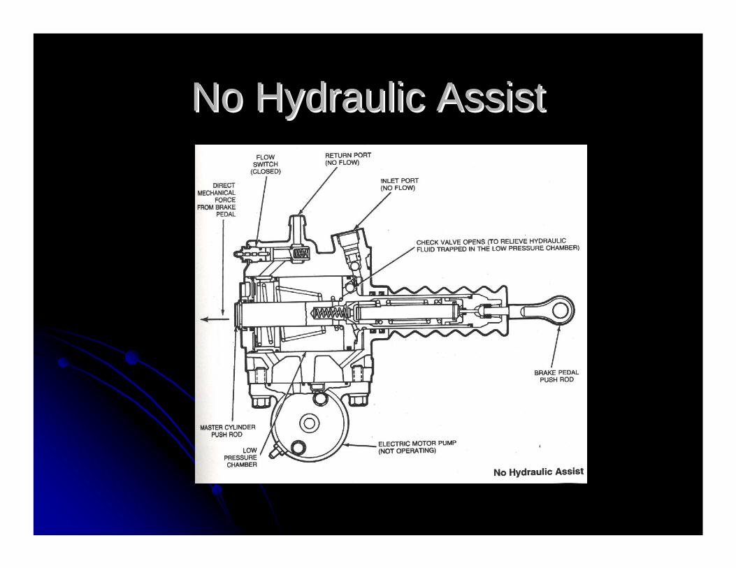
No Hydraulic AssistNo Hydraulic Assist
In the unlikely event that complete loss of In the unlikely event that complete loss of all power assist occurs during vehicle all power assist occurs during vehicle operation, it is still possible to bring the operation, it is still possible to bring the vehicle to a controlled stop by pushvehicle to a controlled stop by push--through manual application of the master through manual application of the master cylinder. However brake pedal effort will cylinder. However brake pedal effort will be greatly increased and vehicle stopping be greatly increased and vehicle stopping distance will be significantly longer. distance will be significantly longer.
No Hydraulic AssistNo Hydraulic Assist
VERY IMPORTANTVERY IMPORTANTDO NOT ATTEMPT TO DRIVE THE DO NOT ATTEMPT TO DRIVE THE
VEHICLE EXCEPT FOR EMERGENCY VEHICLE EXCEPT FOR EMERGENCY REMOVAL FROM THE ROADWAYREMOVAL FROM THE ROADWAY