hydrotechnik minimess® catalog
TRANSCRIPT

MINIMESS®

Preface
Pioneering technology and innovative solutionsThe company philosophy “Test with confidence” has a long tradition at Hydrotechnik. In 1964, theMINIMESS® - ball sealing threaded test point and plug-in coupling was invented and proved to be amajor advance for pressure measurement on hydraulic systems.
The benefits of this innovative development were vast because up till then, pressure measurementshad been mainly carried out with help of fixed mounted pressure gauges and with enormous expendi-ture. Now, with Hydrotechnik, the use of pressure sensors and pressure gauges could now be carried outquickly, safely and without any interruptions to plant. This is why we say “Test with confidence”.
The next step: New sealing techniqueAs a consequent development of the MINIMESS® - plug-in and threadedtest point with ball sealing from the 60’s, the patented leakage-freecoupling with soft-sealing was introduced.The added benefits to our customers were at the forefront ofour mind, meaning cleaner handling and new applications inproblematic areas like water protection zones and for thefirst time also in gas application, which establishedHYDROTECHNIK even further in the market.
p/T coupling - for requirements in thepresent and the futureHandling, operating characteristics and quality of the MINI-MESS® - test points have been proved a million times, ho-wever “Test with confidence” stands also for research anddevelopment. In order to offer more innovative products to ourcustomers, new demands in the automation and robotics sectorcaused the next development. Our aim was to avoid measuringpessure and temperature with separate sensors. Instead, we wan-ted to use one common Test Point.
Hydrotechnik developed the p/T - coupling, which was lengthened and de-signed to accept a temperature probe which actually gets in contact with themedium. Perfect heat transmission between the medium and the temperature sensoris guaranteed.
Reliability and qualityThe high quality standard, connected with large process-security and non-leakage are reached by amodern automatic assembling with integrated leak testing.
Due to this fact, ultra-modern test- and measurement couplings from Hydrotechnik are available to eve-ryone.
Today, MINIMESS® - couplings are the basic requirement for measuring and testing in industryworldwide, due to its enormous environmental security and economy.
Everything
begins at
one point.
Convince yourself and “Test with confidence”.

MINIMESS®–One product for many applications
Hydraulic control blocks
Mobile load sensing systems
Cylinder controls
Pump drives
Servo valves
ContentsMINIMESS®-Index
6 MINIMESS® – an overview
7 MINIMESS®-Technical data
8 MINIMESS®-1620 Test PointsMetric DKO, Tee Adaptors - 1620Metric DKO 1620 Male/Female Tee Adaptors1620 Bulkhead Adaptors1620 Standpipe adaptor 37°-edged screwing SAE J514MINIMESS®-1620 pressure gauge connection for bulkhead fittingMINIMESS®-1620 pressure gauge - direct connection1620 90° Swivel screw connectionMINIMESS®-1620 Hose adaptors
12 MINIMESS®-1620 p/T Test Points
13 MINIMESS®-1215 Test PointsMetric DKO, Tee Adaptors - 12151215 Bulkhead AdaptorsMINIMESS®-1215 pressure gauge connection for bulkhead fittingMINIMESS®-1215 pressure gauge - direct connection1215 90° Swivel screw connectionMINIMESS®-1215 hose adaptors
16 MINIMESS®-1615 Test PointsMINIMESS®-1615 specialised optionsMetric DKO, Tee Adaptors - 16151615 Bulkhead adaptorsMINIMESS®-1615 pressure gauge connection for bulkhead fittingMINIMESS®-1615 pressure gauge - direct connection1615 90° Swivel screw connectionMINIMESS®-1615 Hose Adaptors
19 MINIMESS®-1604 Test Points
19 MINIMESS®-Plug-in Test Points
20 MINIMESS®-Pressure inhibitors and accessories
21 MINIMESS®-Technical data on DN2 and DN4 microbore hose
23 Mounting suggestions of MINIMESS® microbore hose assemblies
24 MINIMESS®-DN2 microbore hose assemblies 1620,1615, 1215 and plug-in seriesMeasuring hoses DN2 with protection against leakage
25 MINIMESS®-DN4 microbore hose assemblies 1604Measuring hoses DN4 with protection against leakage
26 Order chart for hose material and accesories DN2 and DN4
27 Selectable hose ends for DN2 and DN4 hose
31 Accessories for MINIMESS®-hoses
32 Digital pressure gaugesMINIMESS®-1620 Test kit with two digital pressure gauges
33 Analogue pressure gaugesMINIMESS®-1620 Test kit with two analogue gauges
35 Accumulator charging and testing devices
36 MINIMESS®-gas charging valve 1615
37 Accumulator charging and testing devices
37 Gas charging and testing devices with pressure reducer valve
37 Gas charging and flushing devices with pressure reducer valve
38 Compatibility table
39 Conversion table of pressure measuring units

6 1 MPa =10 bar
MINIMESS®-1620
MINIMESS®-1215
MINIMESS®-1615
MINIMESS®-1604
Free-cutting steel1.0718
Stainless steel1.4571
NBR (Perbunan)
FKM (Viton)63,0 MPa
Max Pressure
DN 2
Nominal Bore
M 16 x 2
Thread ofscrew-cap
Material Sealing material
8
Page
MINIMESS®– an overview
Free-cutting steel1.0718
Stainless steel1.4571
NBR (Perbunan)
FKM (Viton)63,0 MPa
Max Pressure
DN 2
Nominal Bore
Fixing thread 12
Thread ofscrew-cap
Material Sealing material
13
Page
Free-cutting steel1.0718
Stainless steel1.4571
NBR (Perbunan)
FKM (Viton)63,0 MPa
Max Pressure
DN 2
Nominal Bore
M 16 x 1,5
Thread ofscrew-cap
Material Sealing material
16
Page
Free-cutting steel1.0718
NBR (Perbunan)
FKM (Viton)40,0 MPa
Max Pressure
DN 4
Nominal Bore
Fixing thread 16
Thread ofscrew-cap
Material Sealing material
19
Page
MINIMESS®-p/T 1620
Free-cutting steel1.0718
NBR (Perbunan)
FKM (Viton)63,0 MPa
Max Pressure
DN 2
Nominal Bore
M 16 x 2
Thread ofscrew-cap
Material Sealing material
12
Page

71 MPa =10 bar
MaterialCoupling body and metal cap made of steel 1.0718Note: Unless stated otherwise, all products shown in this catalogueare made of free-cutting steel 1.0718
SealingInternal primary- and secondary sealing as well as sealing forscrew-in threads are made of NBR (Perbunan). Option in FKM (Viton).
VibrationNBR (Perbunan) and/or FKM (Viton) O-ring to prevent cap looseningdue to vibration.
Screw-in threadLarge range of threads are available.
Media applicationSuitable for hydraulic- and other oils on mineral oil basis
Temperature ranges at applications withmetal cap (standard)Sealing made of NBR (Perbunan): -25 °C to +100 °C,
for a short time, canbe also used up to +120 °C
Sealing made of FKM (Viton) as option: -20 °C to +200 °C
Application with plastic cap (option)and for both sealing materials: -20 °C to +100 °C
Application for low temperature: -54 °C on request
MINIMESS®-Technical dataMax. working pressure 63 MPa (630 bar) according to ISO 15171-2
Thread form data
G
tb
45°
G
ø d1
k b
45°ø d2
ta
z°G
ø d
tb
45°
a
2,5+0
,2
0,5+0
,15
G
ø d
tb
30°
t
G45°
Thread port according toDIN 3852 part 1 and part2, form Z (sealed withsuitable sealant)
Thread port according to SAEJ 514(UNF) or according to ISO 6149-1(sealed with O-ring)
Thread Port up to Ø d accor-ding to DIN 3852 part 1 andpart 2, from X (sealed withflat seal or sealing edge)
Thread Port according toHYDROTECHNIK standardN901-01-14 (sealed withO-ring)
Thread Portaccording toANSI/ASME B1.20.1-1983 (selfsealing thread)
Form E Form F / B Form G Form H
G b t
ISO 7 / I - R1/8 5,5 9,5ISO 7 / I - R1/4 8,5 13,5
G d1 d2 b k t a z°
7/16-20 UNF 21,0 12,4 11,5 2,4 14,0 1,6 12,01/2-20 UNF 23,0 14,0 11,5 2,4 14,0 1,6 12,09/16-18 UNF 25,0 15,6 12,7 2,5 15,5 1,6 12,03/4-16 UNF 30,0 20,6 14,3 2,5 17,5 2,4 15,0
G d a b t
ISO 228-G 1/8 15,0 1,0 8,0 13,0ISO 228-G 1/4 20,0 1,5 12,0 18,5ISO 228-G 3/8 23,0 2,0 12,0 18,5ISO 228-G 1/2 27,0 2,5 14,0 22,0M 12 x 1,5 18,0 1,5 12,0 18,5M 14 x 1,5 20,0 1,5 12,0 18,5M 16 x 1,5 22,0 1,5 12,0 18,5
G d b t
M 8 x 1 9,5 9,0 13,0M 10 x 1 11,5 9,0 13,0
G t
1/8 NPTF 12,01/4 NPTF 17,51/2 NPTF 22,9
SAE J 514 (UNF)
M 10 x 1 19,0 11,1 10,0 1,6 11,5 1,0 12,0M 12 x 1,5 19,0 13,8 11,5 2,4 14,0 1,5 15,0M 14 x 1,5 21,0 15,8 11,5 2,4 14,0 1,5 15,0M 16 x 1,5 24,0 17,8 13,0 2,4 15,5 1,5 15,0
ISO 6149-1
Form C
Gradually change over to chrome (VI)-freesurface treatment
leckage
free

8 1 MPa =10 bar
MINIMESS®-1620 Test Points
M 8 x 1*
M 10 x 1
M 12 x 1,5
M 14 x 1,5
M 16 x 1,5
M 14 x 1,5
ISO 228-G 1/8
ISO 228-G 1/4
ISO 228-G 3/8
1/8 NPTF
1/4 NPTF
7/16-20 UNF
9/16-18 UNF
ISO 7/I-R 1/8
ISO 7/I-R 1/4
6
12
30
40
60
45
18
40
60
–
–
20
35
–
–
41
37,5
36
36
36
35,5
38
36
36
33
33
37
36
33
33
8,5
8,5
10
10
10
11
8
10
10
9,5
16,5
9
10
13
13
Form G
Form F
Form E**
Form F
Form H
Form E
Form C
Option
Other materials, designs, sealing and screw-in threads on request.We reserve the right to carry out technical modifications.
25 MPa
63 MPa
40 MPa
63 MPa
40 MPa
63 MPa
40 MPa
63 MPa
TorqueinNm Technical data
Material:Free cutting steel1.0718
Part-numberwith NBR - sealing
Metalcap
Material:Stainless steel1.4571
Part-numberwith FKM - sealing
Metalcap
Material:Free cutting steel1.0718
Part-numberwith NBR - sealing
Plasticcap
2103-01-32.00
2103-01-33.00
2103-01-13.00
2103-01-14.00
2103-01-15.00
2103-01-96.00
2103-01-17.00
2103-01-18.00
2103-01-16.00
2103-01-46.00
2103-01-47.00
2103-01-21.00
2103-01-53.00
2103-01-40.00
2103-01-41.00
17
17
17
19
22
19
17
19
22
17
17
17
19
17
17
2103-30-32.00
2103-30-33.00
2103-30-13.00
2103-30-14.00
2103-30-15.00
2103-30-96.00
2103-30-17.00
2103-30-18.00
2103-30-16.00
2103-30-46.00
2103-30-47.00
2103-30-21.00
2103-30-53.00
2103-30-40.00
2103-30-41.00
on request
2703-01-33.10
on request
2703-01-14.10
on request
on request
2703-01-17.10
2703-01-18.10
on request
on request
2703-01-47.10
on request
on request
on request
on request
H+
3m
m
Metal cap with anti vibration O-ring Plastic cap – Vibration Proof
p max Hin mm
iin mm
SWin mm
ThreadG
Type of sealA
Hi
G
SW
20ø
10For sealing in FKM (Viton) Exchange end digits from 00 to 10
* M8x1 - Please do not use for new machinery design.** Form E – ISO 6149-2.

50,5
50,5
52,5
52,5
54,5
56,5
60,5
60,5
68,5
70,5
91 MPa =10 bar
MINIMESS®-1620 Test PointsMetric DKO, Tee Adaptors - 1620For solder free screw-in pipe connections according to DIN 2353; free-cutting steel 1.0718; sealing NBR
Options
All sealing made of Viton with metal cap (when ordering, exchange end digits from 00 to 10) 10
With mounted plastic cap (when ordering, exchange end digits from 00 to 90) 90
All sealing made of Viton with plastic cap (when ordering, exchange end digits from 00 to 95) 95
SW
L0
20ø
dø
G
SW
SW17
L0
20ø
dø
G
SW2
SW1SW17
20ø
Gdø
ca.L1
L0
L2
DKO - measuring connection with 24° sealing cone and Test Points incorporated.Elastic Perbunban O-ring at the sealing cone.
Fig. 1 Fig. 2
Tee adapter c/w cutting rings with union nuts.Test Points incorporated.
L 6
L 8
L 10
L 12
L 15
L 18
L 22
L 28
L 35
L 42
M 12 x 1,5
M 14 x 1,5
M 16 x 1,5
M 18 x 1,5
M 22 x 1,5
M 26 x 1,5
M 30 x 2
M 36 x 2
M 45 x 2
M 52 x 2
31,5 MPa
16 MPa
S 6
S 8
S 10
S 12
S 14
S 16
S 20
S 25
S 30
S 38
M 14 x 1,5
M 16 x 1,5
M 18 x 1,5
M 20 x 1,5
M 22 x 1,5
M 24 x 1,5
M 30 x 2
M 36 x 2
M 42 x 2
M 52 x 2
63 MPa
40 MPa
31,5 MPa
1
2
52
52
52
52
52
52
60
61
63
63
14
17
19
22
27
32
36
41
50
60
Lo SW
2103-93-06.00
2103-93-08.00
2103-93-10.00
2103-93-12.00
2103-93-15.00
2103-93-18.00
2103-40-22.00
2103-40-28.00
2103-40-35.00
2103-40-42.00
Part-number
1
2
1
2
52
52
52
52
63
52
63
64,5
66
69
17
19
22
24
27
30
36
46
50
60
2103-94-06.00
2103-94-08.00
2103-94-10.00
2103-94-12.00
2103-41-14.00
2103-94-16.00
2103-41-20.00
2103-41-25.00
2103-41-30.00
2103-41-38.00
20,5
20,5
22,5
22,5
24,5
23,5
27,5
27,5
25,5
24,5
L1 L2
49,5
49,5
49,5
49,5
52,5
53,5
55,5
58
60,5
65
Lo
24
24
24
24
30
32
36
41
46
55
SW1
14
17
19
22
27
32
36
41
50
60
SW2
2103-11-06.00
2103-11-08.00
2103-11-10.00
2103-11-12.00
2103-11-15.00
2103-11-18.00
2103-11-22.00
2103-11-28.00
2103-11-35.00
2103-11-42.00
Part-number
54,5
54,5
56,5
56,5
62,5
62,5
68,5
74,5
80,5
91
24,5
24,5
23,5
23,5
26,5
25,5
25,5
26,5
27,5
29
49,5
49,5
49,5
49,5
51
52,5
55,5
58
60,5
65
24
24
24
24
27
30
36
41
46
55
17
19
22
24
27
30
36
46
50
60
2103-12-06.00
2103-12-08.00
2103-12-10.00
2103-12-12.00
2103-12-14.00
2103-12-16.00
2103-12-20.00
2103-12-25.00
2103-12-30.00
2103-12-38.00
SeriesØ d
p max ThreadG
Fig.
Safety ring
10 1 MPa =10 bar
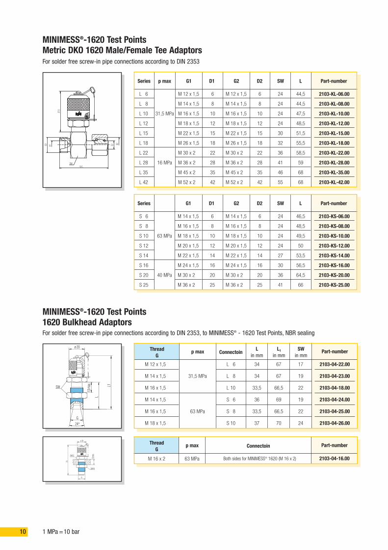
MINIMESS®-1620 Test Points1620 Bulkhead AdaptorsFor solder free screw-in pipe connections according to DIN 2353, to MINIMESS® - 1620 Test Points, NBR sealing
SW L1
L
13m
ax.
G
20ø
24°
SW
37,5
G1 D2
ca.L
D1 G2
SW22
SW19
13m
ax.
70
20ø
G
34
34
33,5
36
33,5
37
67
67
66,5
69
66,5
70
L 6
L 8
L 10
S 6
S 8
S 10
17
19
22
19
22
24
Connectoin
31,5 MPa
63 MPa
p max
M 12 x 1,5
M 14 x 1,5
M 16 x 1,5
M 14 x 1,5
M 16 x 1,5
M 18 x 1,5
ThreadG
Lin mm
L1in mm
SWin mm
2103-04-22.00
2103-04-23.00
2103-04-18.00
2103-04-24.00
2103-04-25.00
2103-04-26.00
Part-number
Connectoin
63 MPa
p max
M 16 x 2
ThreadG
2103-04-16.00
Part-number
Both sides for MINIMESS® 1620 (M 16 x 2)
6
8
10
12
15
18
22
28
35
42
M 12 x 1,5
M 14 x 1,5
M 16 x 1,5
M 18 x 1,5
M 22 x 1,5
M 26 x 1,5
M 30 x 2
M 36 x 2
M 45 x 2
M 52 x 2
D1
L 6
L 8
L 10
L 12
L 15
L 18
L 22
L 28
L 35
L 42
Series G2
M 12 x 1,5
M 14 x 1,5
M 16 x 1,5
M 18 x 1,5
M 22 x 1,5
M 26 x 1,5
M 30 x 2
M 36 x 2
M 45 x 2
M 52 x 2
G1
6
8
10
12
15
18
22
28
35
42
D2
24
24
24
24
30
32
36
41
46
55
SW
44,5
44,5
47,5
48,5
51,5
55,5
58,5
59
68
68
L
2103-KL-06.00
2103-KL-08.00
2103-KL-10.00
2103-KL-12.00
2103-KL-15.00
2103-KL-18.00
2103-KL-22.00
2103-KL-28.00
2103-KL-35.00
2103-KL-42.00
Part-number
6
8
10
12
14
16
20
25
M 14 x 1,5
M 16 x 1,5
M 18 x 1,5
M 20 x 1,5
M 22 x 1,5
M 24 x 1,5
M 30 x 2
M 36 x 2
D1
S 6
S 8
S 10
S 12
S 14
S 16
S 20
S 25
Series G2
M 14 x 1,5
M 16 x 1,5
M 18 x 1,5
M 20 x 1,5
M 22 x 1,5
M 24 x 1,5
M 30 x 2
M 36 x 2
G1
6
8
10
12
14
16
20
25
D2
24
24
24
24
27
30
36
41
SW
46,5
48,5
49,5
50
53,5
56,5
64,5
66
L
2103-KS-06.00
2103-KS-08.00
2103-KS-10.00
2103-KS-12.00
2103-KS-14.00
2103-KS-16.00
2103-KS-20.00
2103-KS-25.00
Part-number
MINIMESS®-1620 Test PointsMetric DKO 1620 Male/Female Tee AdaptorsFor solder free screw-in pipe connections according to DIN 2353
p max
31,5 MPa
16 MPa
63 MPa
40 MPa
111 MPa =10 bar
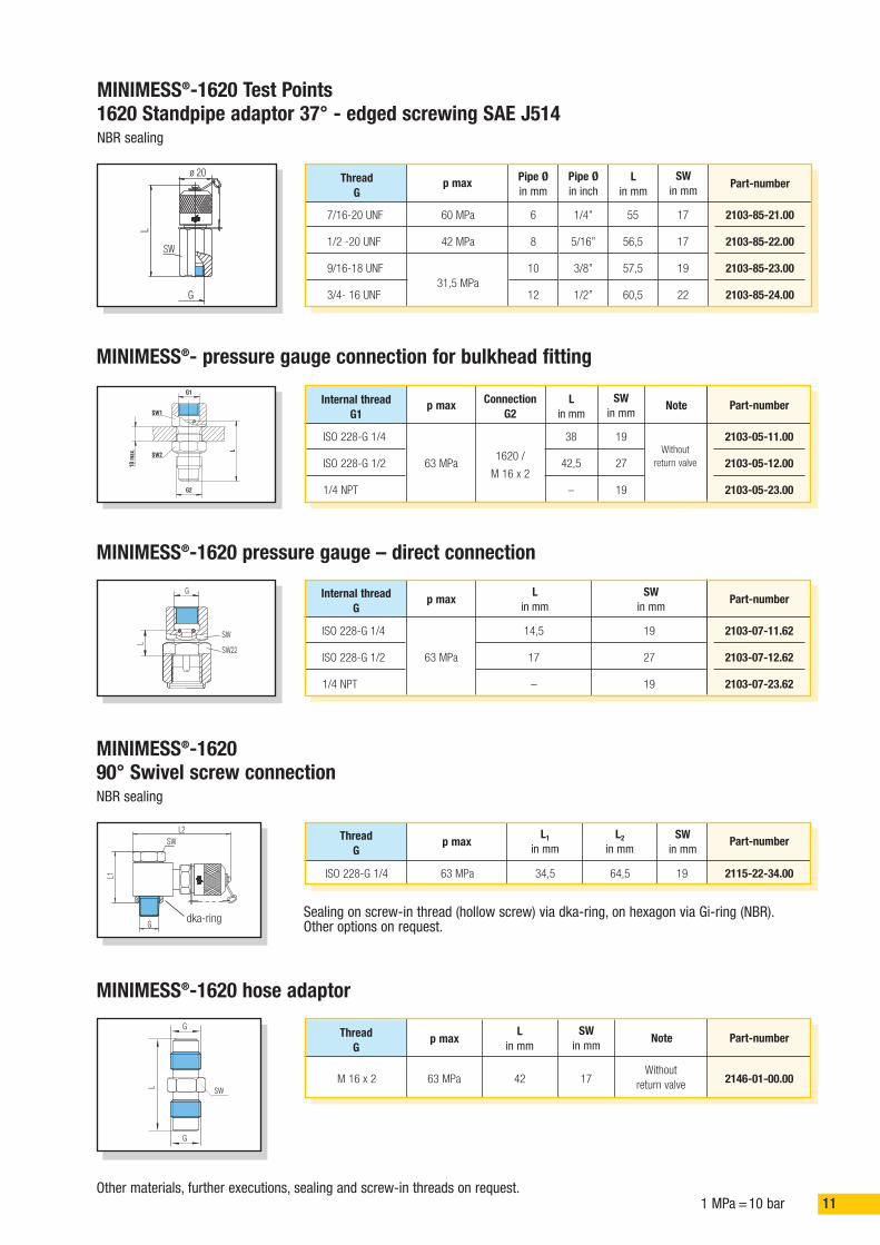
MINIMESS®-1620 Test Points1620 Standpipe adaptor 37° - edged screwing SAE J514NBR sealing
MINIMESS®- pressure gauge connection for bulkhead fitting
MINIMESS®-1620 pressure gauge – direct connection
ø 20
L
G
SW
SW1
SW2
L
10m
ax.
G1
G2
SW22
SW
L
G
1/4”
5/16”
3/8”
1/2”
55
56,5
57,5
60,5
6
8
10
12
17
17
19
22
Pipe Øin mm
60 MPa
42 MPa
31,5 MPa
p max
7/16-20 UNF
1/2 -20 UNF
9/16-18 UNF
3/4- 16 UNF
ThreadG
Pipe Øin inch
Lin mm
SWin mm
Other materials, further executions, sealing and screw-in threads on request.
2103-85-21.00
2103-85-22.00
2103-85-23.00
2103-85-24.00
Part-number
MINIMESS®-162090° Swivel screw connectionNBR sealing
SW
G
L2
L1 64,534,5 1963 MPa
p max
ISO 228-G 1/4
L2in mm
L1in mm
SWin mm
2115-22-34.00
Part-number
38
42,5
–
19
27
19
1620 /
M 16 x 2
Withoutreturn valve
ConnectionG2
63 MPa
p max
ISO 228-G 1/4
ISO 228-G 1/2
1/4 NPT
Lin mm
SWin mm
Note
2103-05-11.00
2103-05-12.00
2103-05-23.00
Part-number
14,5
17
–
19
27
19
63 MPa
p max
ISO 228-G 1/4
ISO 228-G 1/2
1/4 NPT
Lin mm
SWin mm
2103-07-11.62
2103-07-12.62
2103-07-23.62
Part-number
Internal threadG1
Internal threadG
Sealing on screw-in thread (hollow screw) via dka-ring, on hexagon via Gi-ring (NBR).Other options on request.
MINIMESS®-1620 hose adaptor
L
G
G
SW1742
Withoutreturn valve63 MPaM 16 x 2
SWin mm
Lin mm
Note
2146-01-00.00
Part-number
ThreadG
ThreadG
p max
dka-ring

12 1 MPa =10 bar
G
SW
Hi
L0
20ø
L
ISO 228-G 1/4
M 10 x 1
Form F
Form G
40
12
36,5
3863 MPa
TorqueinNm Technical data
Material:Free cutting steel1.0718
Part-numberwith NBR - sealing
Metalcap
2149-04-15.13
2149-04-19.13
p max Hin mm
10
8,5
iin mm
16
16
L0in mm
14,5
14,5
Lin mm
19
17
SWin mm
ThreadG
Type of sealingA
MINIMESS®-1620 p/T Test Pointsfor pressure and temperature measurement
Option
Other materials, further options, sealing and screw-in threads on request.We reserve the right to carry out technical modifications.
27*)
12
G1/4ø20
45°
1,5
25,5
*)9
2,5+
0,2
0,5+
0,15
ø11,5
M10x1
30°
For FKM (Viton) - exchange end digits from 13 to 53 53
*) = recommended min. depth of drill
Form F Form G
Thread formsonly for p/T -screw coupling
L0 = max. immersion depth in coupled state, L = not coupled state

131 MPa =10 bar
MINIMESS®-1215 Test Points
M 8 x 1*
M 10 x 1
M 12 x 1,5
M 14 x 1,5
ISO 228-G 1/8
ISO 228-G 1/4
1/8 NPTF
1/4 NPTF
7/16-20 UNF
9/16-18 UNF
ISO 7/I-R 1/8
6
12
30
40
18
40
–
–
20
35
–
30
30
29
29
30
29
26
26
29
28
26
8,5
8,5
10
10
8
10
12
15
9
10
12
Form G
Form F
Form H
Form E
Form C
Option
Other materials, further options, sealing and screw-in threads on request.We reserve the right to carry out technical modifications.
* M 8 x 1 – please do not use for new constructions.
25 MPa
63 MPa
40 MPa
63 MPa
40 MPa
63 MPa
40 MPa
TorqueinNm Technical data
Material:Free cutting steel1.0718
Part-numberwith NBR - sealing
Metalcap
Material:Stainless steel1.4571
Part-numberwith FKM - sealing
Metalcap
Material:Free cutting steel1.0718
Part-numberwith NBR - sealing
Plasticcap
2101-06-32.00
2101-06-33.00
2101-06-13.00
2101-06-14.00
2101-06-17.00
2101-06-18.00
2101-06-46.00
2101-06-47.00
2101-06-21.00
2101-06-53.00
2101-06-40.00
14
14
17
19
14
19
14
14
17
19
14
2101-01-32.00
2101-01-33.00
2101-01-13.00
2101-01-14.00
2101-01-17.00
2101-01-18.00
2101-01-46.00
2101-01-47.00
2101-01-21.00
2101-01-53.00
2101-01-40.00
on request
2701-06-33.10
on request
on request
on request
2701-06-18.10
on request
2701-06-47.10
on request
on request
on request
For FKM (Viton) - Exchange end digits from 00 to 10 10
G
i
SW
H
17
Metal cap with anti vibration O-ringPlastic cap with integrated safetydevice against vibration
p max Hin mm
iin mm
SWin mm
ThreadG
Type of sealingA
SW17
20ø
H+3
mm

14 1 MPa =10 bar
Other materials, further options, sealing and screw-in threads on request.
50,5
50,5
52,5
52,5
54,5
56,5
60,5
60,5
68,5
70,5
Fig.
MINIMESS®-1215 Test PointsMetric DKO, Tee Adaptors-1215For solder free screw-in pipe connections according to DIN 2353; execution free-cutting steel 1.0718; sealing NBR
Options
All sealing made of Viton with metal cap (when ordering, exchange end digits from 00 to 10)
With mounted plastic cap (when ordering, exchange end digits from 00 to 90) 95
SW
SW14
L0
17ø
dø
G
SW
SW14L0
17ø
dø
G
SW2
SW1
SW14
ca. L1
Gdø
17ø
L0
L2
DKO - measuring connection with 24° sealing cone Safety ring and Test Pointsincorporated. Elastic Perbunban O-ring at the sealing cone.
Fig. 1 Fig. 2
Tee adapter c/w cutting rings and union nuts.Test Points incorporated.
L 6
L 8
L 10
L 12
L 15
L 18
L 22
L 28
L 35
L 42
M 12 x 1,5
M 14 x 1,5
M 16 x 1,5
M 18 x 1,5
M 22 x 1,5
M 26 x 1,5
M 30 x 2
M 36 x 2
M 45 x 2
M 52 x 2
31,5 MPa
16 MPa
S 6
S 8
S 10
S 12
S 14
S 16
S 20
S 25
S 30
S 38
M 14 x 1,5
M 16 x 1,5
M 18 x 1,5
M 20 x 1,5
M 22 x 1,5
M 24 x 1,5
M 30 x 2
M 36 x 2
M 42 x 2
M 52 x 2
63 MPa
31,5 MPa
40 MPa
1
2
62
62
62
58
51,5
52,5
52,5
53,5
55,5
55,5
17
19
19
22
27
32
36
41
50
60
Lo SW
2101-40-06.90
2101-40-08.90
2101-40-10.90
2101-40-12.90
2101-40-15.90
2101-40-18.90
2101-40-22.90
2101-40-28.90
2101-40-35.90
2101-40-42.90
Part-number
1
2
62
62
62
58
55
55
55,5
57
58,5
61,5
17
19
22
24
27
30
36
46
50
60
2101-41-06.90
2101-41-08.90
2101-41-10.90
2101-41-12.90
2101-41-14.90
2101-41-16.90
2101-41-20.90
2101-41-25.90
2101-41-30.90
2101-41-38.90
20,5
20,5
22,5
22,5
24,5
23,5
27,5
27,5
25,5
24,5
L1 L2
42
42
42
42
45
46
48
50,5
53
57,5
Lo
24
24
24
24
30
32
36
41
46
55
SW1
14
17
19
22
27
32
36
41
50
60
SW1
2101-11-06.90
2101-11-08.90
2101-11-10.90
2101-11-12.90
2101-11-15.90
2101-11-18.90
2101-11-22.90
2101-11-28.90
2101-11-35.90
2101-11-42.90
Part-number
54,5
54,5
56,5
56,5
62,5
62,5
68,5
74,5
80,5
91
24,5
24,5
23,5
23,5
26,5
25,5
25,5
26,5
27,5
29
42
42
42
42
43,5
45
48
50,5
53
57,5
24
24
24
24
27
30
36
41
46
55
17
19
22
24
27
30
36
46
50
60
2101-12-06.90
2101-12-08.90
2101-12-10.90
2101-12-12.90
2101-12-14.90
2101-12-16.90
2101-12-20.90
2101-12-25.90
2101-12-30.90
2101-12-38.90
SeriesØ d p max Thread
G
Safety ring
00

151 MPa =10 bar
MINIMESS®-1215 Test Points1215 Bulkhead AdaptorsFor solder free screw-in pipe connections according to DIN 2353; execution free-cutting steel 1.0718; sealing NBR
MINIMESS®-1215 pressure gauge connection for bulkhead fitting
MINIMESS®-pressure gauge – direct connection
SW60
,5
17ø
L
13m
ax.
Gd
24°
SW19
SW19
65
13m
ax.
G
SW2
SW1
G2
G1
10m
ax.
SW 22
SW
L
G
34
34
36
60,5
60,5
62,5
L 6
L 8
S 6
17
19
19
Connection
31,5 MPa
63 MPa
p max
M 12 x 1,5
M 14 x 1,5
M 14 x 1,5
ThreadG
Lin mm
L1in mm
SWin mm
2101-04-22.90
2101-04-23.90
2101-04-24.90
Part-number
31
38,5
–
19
27
22
1215Without
return valve63 MPa
p max
ISO 228-G 1/4
ISO 228-G 1/2
1/4 NPT
L in mm(approx.)
SWin mm
Note
2101-05-11.00
2101-05-12.00
2101-05-23.00
Part-number
14,5
17
–
19
27
19
63 MPa
p max
ISO 228-G 1/4
ISO 228-G 1/2
1/4 NPT
Lin mm
SWin mm
2101-07-11.62
2101-07-12.62
2101-07-23.62
Part-number
Internal threadG1
Internal threadG
MINIMESS®-1215 Test Points1215 90° Swivel screw connection
SW
G
L2
L1
34,5 46 1963 MPa
p max
ISO 228-G 1/4
L1in mm
L2in mm
SWin mm
2115-22-14.00
Part-numberThreadG
Sealing on screw-in thread (hollow screw) via dka-ring, on hexagon via Gi-ring (NBR).Other options on request.
Other materials, further options, sealing and screw-in threads on request.
MINIMESS®-1215 hose adaptors
L
G
G
SW
29 14 Without return valve63 MPa
p max
Fixing thread 12
Lin mm
SWin mm
Note
2146-20-00.20
Part-numberThreadG
ConnectionG2
Connectionp max
Fixing thread 12
ThreadG
2101-04-16.90
Part-number
On both sides MINIMESS® - 1215 connection63 MPa
dka-ring
L1
16 1 MPa =10 bar
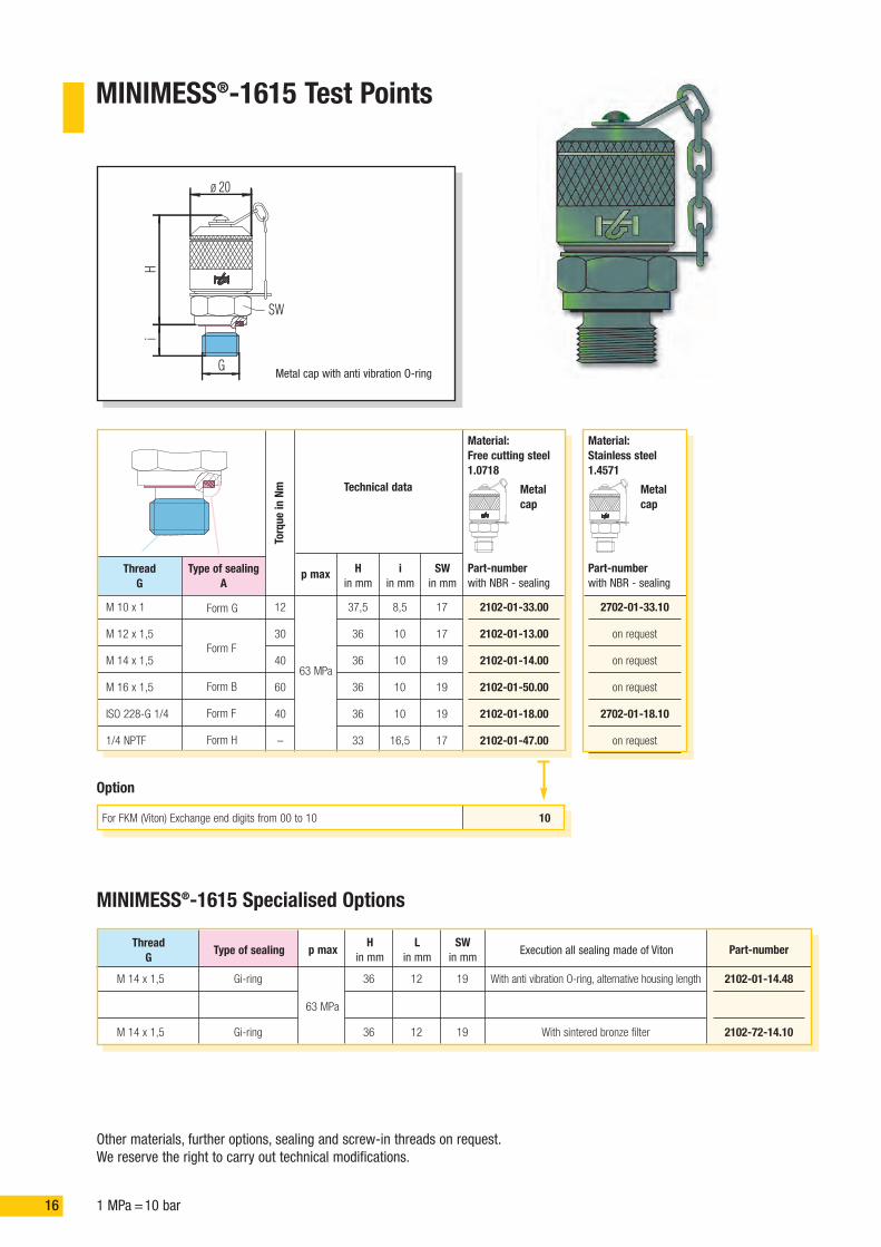
MINIMESS®-1615 Test Points
M 10 x 1
M 12 x 1,5
M 14 x 1,5
M 16 x 1,5
ISO 228-G 1/4
1/4 NPTF
12
30
40
60
40
–
37,5
36
36
36
36
33
8,5
10
10
10
10
16,5
Form G
Form F
Form B
Form F
Form H
Option
Other materials, further options, sealing and screw-in threads on request.We reserve the right to carry out technical modifications.
63 MPa
TorqueinNm Technical data
Material:Free cutting steel1.0718
Part-numberwith NBR - sealing
Metalcap
Material:Stainless steel1.4571
Part-numberwith NBR - sealing
Metalcap
2102-01-33.00
2102-01-13.00
2102-01-14.00
2102-01-50.00
2102-01-18.00
2102-01-47.00
17
17
19
19
19
17
2702-01-33.10
on request
on request
on request
2702-01-18.10
on request
For FKM (Viton) Exchange end digits from 00 to 10 10
Hi
G
SW
20ø
Metal cap with anti vibration O-ring
p max Hin mm
iin mm
SWin mm
ThreadG
Type of sealingA
MINIMESS®-1615 Specialised Options
63 MPa
Gi-ring
Gi-ring
M 14 x 1,5
M 14 x 1,5
p max
36
36
Hin mm
12
12
Lin mm
19
19
With anti vibration O-ring, alternative housing length
With sintered bronze filter
SWin mm
Execution all sealing made of Viton
2102-01-14.48
2102-72-14.10
Part-numberThreadG
Type of sealing

171 MPa =10 bar
Other materials, further options, sealing and screw-in threads on request.
50,5
50,5
52,5
52,5
54,5
56,5
60,5
60,5
68,5
70,5
Fig.
MINIMESS®-1615 Test PointsMetric DKO, Tee Adaptors-1615For solder free screw-in pipe connections according to DIN 2353; execution free-cutting steel 1.0718; sealing NBR
Option
All sealing made of Viton with metal cap (when ordering, exchange end digits from 00 to 10) 10
SW17SW17
SWSW
L0L0
2020øø
døø
GG
SW
SW17
20ø
L0
G
dø
SW17
SW1
SW2
20ø
ca.L1
L0
Gdø
L2
DKO - measuring connection with 24° sealing cone and Test Points incorporated.Elastic Perbunban O-ring at the sealing cone.
Fig. 1 Fig. 2
Tee adapter c/w cutting rings and union nuts.Test Points incorporated.
L 6
L 8
L 10
L 12
L 15
L 18
L 22
L 28
L 35
L 42
M 12 x 1,5
M 14 x 1,5
M 16 x 1,5
M 18 x 1,5
M 22 x 1,5
M 26 x 1,5
M 30 x 2
M 36 x 2
M 45 x 2
M 52 x 2
31,5 MPa
16 MPa
S 6
S 8
S 10
S 12
S 14
S 16
S 20
S 25
S 30
S 38
M 14 x 1,5
M 16 x 1,5
M 18 x 1,5
M 20 x 1,5
M 22 x 1,5
M 24 x 1,5
M 30 x 2
M 36 x 2
M 42 x 2
M 52 x 2
63 MPa
40 MPa
31,5 MPa
1
2
69,5
69,5
69,5
65,5
59
60
60
61
63
63
14
17
19
22
27
32
36
41
50
60
Lo SW
2102-40-06.00
2102-40-08.00
2102-40-10.00
2102-40-12.00
2102-40-15.00
2102-40-18.00
2102-40-22.00
2102-40-28.00
2102-40-35.00
2102-40-42.00
Part-number
1
2
69,5
69,5
69,5
65,5
62,5
62,5
63
64,5
66
69
17
19
22
24
27
30
36
46
50
60
2102-41-06.00
2102-41-08.00
2102-41-10.00
2102-41-12.00
2102-41-14.00
2102-41-16.00
2102-41-20.00
2102-41-25.00
2102-41-30.00
2102-41-38.00
20,5
20,5
22,5
22,5
24,5
23,5
27,5
27,5
25,5
24,5
L1 L2
49,5
49,5
49,5
49,5
52,5
53,5
55,5
58
60,5
65
L0
24
24
24
24
30
32
36
41
46
55
SW1
14
17
19
22
27
32
36
41
50
60
SW2
2102-11-06.00
2102-11-08.00
2102-11-10.00
2102-11-12.00
2102-11-15.00
2102-11-18.00
2102-11-22.00
2102-11-28.00
2102-11-35.00
2102-11-42.00
Part-number
54,5
54,5
56,5
56,5
62,5
62,5
68,5
74,5
80,5
91
24,5
24,5
23,5
23,5
26,5
25,5
25,5
26,5
27,5
29
49,5
49,5
49,5
49,5
51
52,5
55,5
58
60,5
65
24
24
24
24
27
30
36
41
46
55
17
19
22
24
27
30
36
46
50
60
2102-12-06.00
2102-12-08.00
2102-12-10.00
2102-12-12.00
2102-12-14.00
2102-12-16.00
2102-12-20.00
2102-12-25.00
2102-12-30.00
2102-12-38.00
SeriesØ d p max
ThreadG
Safety ring
18 1 MPa =10 bar
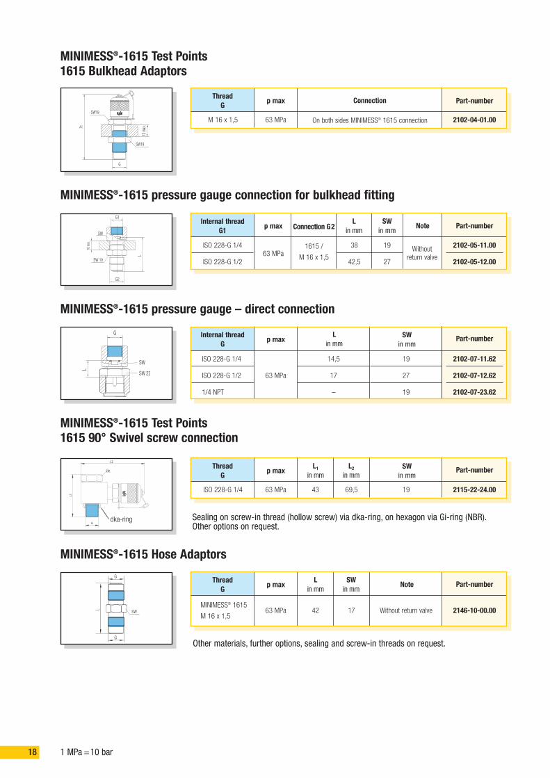
MINIMESS®-1615 Test Points1615 Bulkhead Adaptors
SW19
SW19
G
71
12m
ax.
Connection
63 MPa
p max Part-numberThreadG
M 16 x 1,5
MINIMESS®-1615 pressure gauge connection for bulkhead fitting
MINIMESS®-1615 pressure gauge – direct connection
SW 19
SW
G2
G1
10m
in.
L
G
SW
SW 22
L
38
42,5
19
27
1615 /
M 16 x 1,5Without
return valve
Connection G2
63 MPa
p max
ISO 228-G 1/4
ISO 228-G 1/2
Lin mm
SWin mm
Note
2102-05-11.00
2102-05-12.00
Part-number
14,5
17
–
19
27
19
63 MPa
p max
ISO 228-G 1/4
ISO 228-G 1/2
1/4 NPT
Lin mm
SWin mm
2102-07-11.62
2102-07-12.62
2102-07-23.62
Part-number
Internal threadG1
Internal threadG
MINIMESS®-1615 Test Points1615 90° Swivel screw connection
SW
L1
L2
G
43 69,5 1963 MPa
p max
ISO 228-G 1/4
L1in mm
L2in mm
SWin mm
2115-22-24.00
Part-numberThreadG
Sealing on screw-in thread (hollow screw) via dka-ring, on hexagon via Gi-ring (NBR).Other options on request.
Other materials, further options, sealing and screw-in threads on request.
MINIMESS®-1615 Hose Adaptors
L
G
G
SW 42 17 Without return valve63 MPa
p max
MINIMESS® 1615
M 16 x 1,5
Lin mm
SWin mm
Note
2146-10-00.00
Part-numberThreadG
On both sides MINIMESS® 1615 connection 2102-04-01.00
dka-ring

191 MPa =10 bar
MINIMESS®-1604 Test Points
M 10 x 1
M 14 x 1,5
ISO 228-G 1/4
12
40
40
43
40
40
8,5
10
10
Form G
Form F
Option
40 MPa
TorqueinNm Technical data
Material:Free cutting steel1.0718
Part-numberwith NBR - sealing
Metalcap
Material:Stainless steel1.4571
Part-numberwith NBR - sealing
Metalcap
2106-01-33.00
2106-01-14.00
2106-01-18.00
17
19
19
on request
on request
2706-01-18.10
For FKM (Viton) Exchange end digits from 00 to 10 10
G
i
SW
H
22ø
Metal cap withanti vibration O-ring
p max Hin mm
iin mm
SWin mm
ThreadG
Type of sealingA
MINIMESS®-plug-in Test PointsInternal Ball Sealing
M 8 x 1
M 10 x 1
ISO 7/ I-R 1/8
1/8 NPT
6
12
–
–
17,5
17,5
17,5
17,5
8,5
8,5
8,5
8,5
Form G
Suitablesealant
40 MPa
TorqueinNm Technical data
Material:Free cutting steel1.0718
Part-numberwith FKM - sealing
12
12
12
12
2104-30-32.00
2104-30-33.00
2104-30-40.00
2104-30-43.00
SW
ø15
iH
G
Plastic cap
p max Hin mm
iin mm
SWin mm
ThreadG
Type of sealingA
Material:Stainless steel1.4571
Part-numberwith FKM - sealing
2704-30-32.10
on request
on request
on request

20 1 MPa =10 bar
G230
ø19+0,4
65m
ax.
16,2
G1
15
Connection G 2
ISO 228-G 1/4according toDIN 16288
5110-01-20.00
5110-02-20.00
5110-03-20.00
5110-04-20.00
5110-05-20.00
5110-07-20.00
Part-numberAdjustable pressure range
0,5 bis 0,9 MPa
0,1 bis 2,5 MPa
0,25 bis 6,3 MPa
6,3 bis 10 MPa
10 bis 25 MPa
25 bis 60 MPa
ISO 228-G 1/4according to
DIN 3852Form X
Restrictor valve
SW36
G1ca
.53
ø19
+0,
4
G2
H
53
58
63 MPaAdjustable under
pressure up to 150 barin-line connection
ThreadG2
ISO 228-G 1/4
ISO 228-G 1/2
ISO 228-G 1/4
ISO 228-G 1/4
H p max Execution
5104-03-00.00
5104-02-00.00
Part-numberThreadG1
Damping cartridge (snubber)18
M8x
1
M4
Choking element for dampening of fluidity vibrations2.0401
Material
ø 0,5 mm
Application
2100-24-01.00
Part-numberBorehole: nozzle
M 12 x 1,5
ISO 228-G 1/8
ISO 228-G 1/2
ISO 228-G 3/4
1/2 NPTF
19
19
10
13
10
10
8
14
12
18
Form F
Form H
63 MPa
Part-numberFree cutting steel 1.0718
2134-13-00.00
2134-07-01.00
2134-21-00.00
2134-51-00.00
2134-45-01.01
17
17
27
32
24
p max Lin mm
iin mm
SWin mm
Threaded adaptor M 10 x 1, Form G
Li
G
M 10 x 1
SW
auf Anfrage
2734-07-01.10
2734-21-00.10
2734-51-00.10
on request
M 10 x 1
M 14 x 1,5
ISO 228-G 1/4
25
30
Form G
Form F63 MPa
2126-33-00.01
2126-04-00.01
2126-08-00.01
20
22
p max Lin mm
SWin mm
ThreadG
Screw-in hole
Welding adapter
G
ø D
L
on request
on request
2726-08-00.01
Other materials, further executions, sealing and screw-in threads on request.
Externalthread G
MINIMESS®-Pressure inhibitors and accessories
Pressure limiter valve
ISO 228-G 1/2according toDIN 16288
5110-01-30.00
5110-02-30.00
5110-03-30.00
5110-04-30.00
5110-05-30.00
5110-07-30.00
0,5 bis 0,9 MPa
0,1 bis 2,5 MPa
0,25 bis 6,3 MPa
6,3 bis 10 MPa
10 bis 25 MPa
25 bis 60 MPa
ISO 228-G 1/4according to
DIN 3852Form XPressure gauge connection
Working pressure max. 63 MPa
� Used for protection of pressure gauges against overload
Pressure gauge connectionG 1
Part-numberStainless steel 1.4571
Part-numberFree cutting steel 1.0718
Part-numberStainless steel 1.4571
Typeof sealing

211 MPa =10 bar
MINIMESS®-Technical data on DN2 and DN4 microbore hoseDN 2 and DN 4
A D I D
40,0
63,0
63,0
31,5
45,0
104,0
195,0
150,0
81,0
150,0
pnin MPa
DN 2
DN 2
DN 2
DN 4
DN 4
Nominal width
Standard 400
Standard 630
Low temperature
Standard 315
Standard 450
Design ApplicationpB
in MPa
2
2
2
4
4
IDin mm
5
5
5
8
8
ADin mm
20 mm(below -20 °C
30 mm)
40 mm(below -20 °C
60 mm)
rmin
-20 °C up to +100 °Cshort time up to +120 °C
-54 °C up to +100 °C
-20 °C up to +100 °Cshort time up to +120 °C
Operable temperature range
0 °C 122% 30 °C 110%50 °C 100% 80 °C 86%100 °C 77% 120 °C 68%
Example for calculation:MINIMESS®-hose DN 2/63 MPaat 30 °C pressure utilisationfacto: 63,0 x 1,10 = 69,3 MPa
Pressure utilisation factor
Reference of the specified data: 20 °C – 3 Kpn = operating pressurepB = bursting pressureID = internal diameterAD = external diameterrmin = Minimum bend radius of hosePerforated hose = Jacket of hose is perforated for applications using gas
Definition for the tightness of a MINIMESS®-hose pipe
“Technically tight” describes systems, part systems and functional elements if the leakage rate amounts to < 0,00001 mbar I s-1.
Criteria for selection of hoses and fittings
1. Selection of the hose assembly for the maximum operating pressure (pN):When ordering a hose assembly, you have to pay attention to the operating pressures of the hose material and of the connectionfitting. The lowest pressure determines the max. operating pressure of the complete hose assembly.
2. Selection of hose assembly for use with different media:Hose assemblies can be used with different media, as long as the end connections are suitable. To check the compatability fordifferent media, please refer to our list on page 37.If your medium is not mentioned on page 37, please contact us!
Perforatedhose
Jacket: Polyamide Internal braid: Polyester fibre
Hose Core:Polyamide
Hose structure

22 1 MPa =10 bar
Fittings available with the following materials:Free cutting steel 1.0718 galvanized and chromated, acid-resistant stainless steel 1.4571 (antimagnetic)
1,2
1,0
0,8
0,6
0,4
0,2
0,2 0,4 0,6 0,8 1,0 1,2
3,0
2,5
2,0
1,5
1,0
0,5
0,2 0,4 0,6 0,8 1,0 1,2
Hose CollarDate of manufacture, Month / Year
Safety note: The hose assemblies have to be protected from flames and sharp-edged, hot objects.
We guarantee a very high quality level of our MINIMESS®-systems, as all components are manufactured very precisely and to tighttolerances. All parts in our MINIMESS®-system are easy and safe to use. We reserve the right to carry out technical modifications!
Pressure loss curve of DN 2 hose only Pressure loss curve of DN 2 hose assemblies
Identification Hose: Manufacturer’s stampNominal width DN.Year of manufactureMaterial (PA = polyamid)Operating pressure pN
Pressure loss inMpa per metreof hose lengthwithout fittings,mineral oil: visco-sity 30 mm2 s-1
Pressure loss inMPa through ahose assembly witha length of 1 m, withfittings and Test Pointsof series 1620 on bothsides, mineral oil:viscosity 30 mm2 s-1
0,8
0,7
0,6
0,5
0,4
0,3
0,2
0,1
1 2 3 4 5 6 7 8
4,0
3,0
2,0
1,0
1 2 3 4 5 6 7 8
Pressure loss curve of DN 4 hoses Pressure loss curve of DN 4 hose pipes
Pressure lossin Mpa per metreof hose lengthwithout fittings,mineral oil: visco-sity 30 mm2 s-1
Pressure loss inMPa through ahose assembly witha length of 1 m, withfittings and Test Pointsof series 1604 on bothsides, mineral oil:viscosity 30 mm2 s-1
Pressure
loss
∅p(M
Pa/m
)
Pressure
loss
p(M
Pa/m
)
Pressure
loss
∅p(M
Pa/m
)
Flow rate Q (l/min) Flow rate Q (l/min)
Flow rate Q (l/min) Flow rate Q (l/min)
Pressure
loss
∅p(M
Pa/m
)

231 MPa =10 bar
Mounting suggestions of MINIMESS®-hose assemblies
Working reliability of a system and lifetime of the hose assembly are dependent on thecorrect installation. For this, here are some important notes:
Under load, the length of a hose pipe can change. A shortening causes an additional tensilestress of the hose and the connections. Therefore, the hose pipe needs “slack” in an unpressu-rised state. Please tighten the union nuts only so far using recommended tightening torques.Further tightening does not improve the operation, but can damage the connections.
With curved assemblies, attention has to be paid to the bending radius. Sharp bends have tobe avoided wherever possible. When calculating the length of a hose assembly, you have topay attention to the fact that the connection fittings are not flexible. The correct calculationof the free hose length between the fittings is therefore essential.
90° hose fittings are also available to aid in the fitting of hose assemblies to maximize life andoperation of the assembly.
90° hose fittings can also aid in the fitting of a tidy hose assembly in the tightest of portingrequirements.
Notes for operation and installation
In order to guarantee the operability of hoses and to not reduce assembly life by introducing additional strains, the following pointshave to be taken into consideration:� Hose assemblies may not be strained during operation by external influences like tension, torsion and upset.� The smallest mentioned bending radius of the hose must not be exceeded at any time.� Hose assemblies have to be protected against external damages caused by thermal, chemical or mechanical influences.� Painting or marking of hose assemblies should be avoided.
Notes for storage of hose and hose assemblies
� Store in cool, dry places and avoid direct UV-irradiation.� Sources of radiant heat should be avoided.� Ozone building light fittings and electronic instruments with sparking should be kept away from hoses and hose material (e.g.
mercury vapor discharge lamps)� Optimum storage conditions are temperatures between +15°C and +25°C, a relative air humidity of 65%, as well as shielding
against UV-radiation by special UV-impervious foils.� The storage time should not exceed four years for hose and two years for hose assemblies.
wrong
right
wrong
right
wrong
right
wrong
right

24 1 MPa =10 bar
DN 2 measuring hoses with protection against leakagewith integrated return valve
MINIMESS®-DN 2 microbore hose assembliesFor 1620, 1615, 1215 and plug-in series
The tables show the series 1620
� Suitable for hydraulic and other oils onmineral oil basis
� Same fittings on both sides� Fittings made of free cutting steel 1.0718
Fittings made ofstainless steel 1.4571
Series 1215 (picture 1)(fixing thread)
Exchange number 1 to 7,when ordering
When ordering, replace theletter codes with -AA-AA-.
7
L
L
Fig. 1
200
300
400
500
630
800
1000
1250
1500
2000
2500
3200
4000
5000
L
40 MPa
p max
S 100-AC-AC-0020
S 100-AC-AC-0030
S 100-AC-AC-0040
S 100-AC-AC-0050
S 100-AC-AC-0063
S 100-AC-AC-0080
S 100-AC-AC-0100
S 100-AC-AC-0125
S 100-AC-AC-0150
S 100-AC-AC-0200
S 100-AC-AC-0250
S 100-AC-AC-0320
S 100-AC-AC-0400
S 100-AC-AC-0500
Part-number
63 MPa
p max
S 110-AC-AC-0020
S 110-AC-AC-0030
S 110-AC-AC-0040
S 110-AC-AC-0050
S 110-AC-AC-0063
S 110-AC-AC-0080
S 110-AC-AC-0100
S 110-AC-AC-0125
S 110-AC-AC-0150
S 110-AC-AC-0200
S 110-AC-AC-0250
S 110-AC-AC-0320
S 110-AC-AC-0400
S 110-AC-AC-0500
Part-number
7
-AA-AA-
Series 1615 (picture 1)(M 16 x 1,5)
When ordering, replace theletter codes with -AB-AB-. -AB-AB-
Plug-in seriesMax. pressure 40,0 MPa
When ordering, replace theletter codes with -AI-AI-. -AI-AI-
LSeries 1620(M 16x2)
When ordering, replaceboth letter codes with-AR-AR-. Lmin = 300 mm
-AR-AR- -AR-AR-
Stainless Steel
251 MPa =10 bar
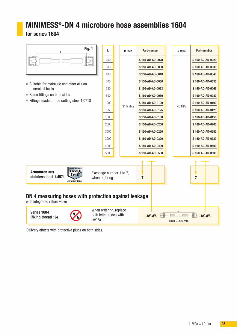
MINIMESS®-DN 4 microbore hose assemblies 1604for series 1604
LFig. 1
DN 4 measuring hoses with protection against leakagewith integrated return valve
Armaturen ausstainless steel 1.4571
Exchange number 1 to 7,when ordering 7
200
300
400
500
630
800
1000
1250
1500
2000
2500
3200
4000
5000
L
31,5 MPa
p max
S 150-AD-AD-0020
S 150-AD-AD-0030
S 150-AD-AD-0040
S 150-AD-AD-0050
S 150-AD-AD-0063
S 150-AD-AD-0080
S 150-AD-AD-0100
S 150-AD-AD-0125
S 150-AD-AD-0150
S 150-AD-AD-0200
S 150-AD-AD-0250
S 150-AD-AD-0320
S 150-AD-AD-0400
S 150-AD-AD-0500
Part-number
45 MPa
p max
S 160-AD-AD-0020
S 160-AD-AD-0030
S 160-AD-AD-0040
S 160-AD-AD-0050
S 160-AD-AD-0063
S 160-AD-AD-0080
S 160-AD-AD-0100
S 160-AD-AD-0125
S 160-AD-AD-0150
S 160-AD-AD-0200
S 160-AD-AD-0250
S 160-AD-AD-0320
S 160-AD-AD-0400
S 160-AD-AD-0500
Part-number
7
Series 1604(fixing thread 16)
When ordering, replaceboth letter codes with-AY-AY-.
Delivery effects with protective plugs on both sides.
Lmin = 300 mm
-AY-AY- -AY-AY-L
� Suitable for hydraulic and other oils onmineral oil basis
� Same fittings on both sides� Fittings made of free cutting steel 1.0718
Stainless Steel

26 1 MPa =10 bar
Order chart for hose material and accessories DN 2 and DN 4
Material of the fittings
Free cutting steel 1.0718 galvanized and chromated
Free cutting steel 1.0718 plus sealing for brake fluid
Acid-resistant stainless steel 1.4571
Options
Hose material DN 4
Perforated standard hose 31,5 MPa
Perforated standard hose 45,0 MPa
Standard
Additional optionsAnti buckling spiral, left side (min. hose length 40 cm)
Anti-buckling spiral, right side (min. hose length 40 cm)
Anti-buckling spiral both sides (min. hose length 40 cm)
Aluminium protection hose (min. hose length 40 cm)
Freely selectable fittingInput as a 2-digit fitting code from page 27 on
Freely selectable fittingInput as a 2-digit fitting code from page 27 on
Length L in cm (e.g. 30 cm = 0030 or 500 cm = 0500)Input as a 4-digit group of figures
Hose material DN 2
Perforated standard hose 40,0 MPa
Perforated standard hose 63,0 MPa
Perforated low temperature hose 63,0 MPa
L in cm
DN 2
DN 4
Part-number
S X X X - X X - X X - X X X X
1
2
7
0
1
2
5
6
0
1
2
3
4
Attention: Aluminium protection in combination with an anti-buckling spiral is not possible.
Stainless Steel
271 MPa =10 bar
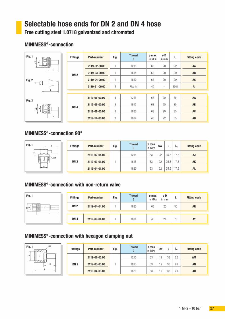
Selectable hose ends for DN 2 and DN 4 hoseFree cutting steel 1.0718 galvanized and chromated
MINIMESS®-connection
L
GDø
Fig. 33
3
3
3
1215
1615
1620
1604
63
63
63
40
20
20
20
22
35
35
35
35
AA
AB
AC
AD
2119-05-00.00
2119-06-00.00
2119-07-00.00
2119-14-00.00
MINIMESS®-connection 90°
1
SW
L
G
L
Fig. 1
1
1215
1615
1620
63
63
63
Fig.p maxin MPa
22
22
22
SW
35,5
35,5
35,5
L
AJ
AK
AL
Fitting code
2119-02-01.00
2119-03-01.00
2119-04-01.00
Part-number L1
17,5
17,5
17,5
MINIMESS®-connection with hexagon clamping nut
SW
G
L
L1
Fig. 1
1
1215
1615
1620
63
63
63
Fig.p maxin MPa
19
19
19
SW
38
38
38
L
AM
AN
AO
Fitting code
2119-02-03.00
2119-03-03.00
2119-04-03.00
Part-number L1
22
20
20
MINIMESS®-connection with non-return valve
1 1620 63
Fig.p maxin MPa
20
ø Din mm
50
L
AR
Fitting code
2119-04-04.00
Part-number
1 1604 40 24 70 AY2119-09-04.00
ThreadG
ThreadG
ThreadG
L
L
GDø
1
1
1
2
1215
1615
1620
Plug-in
63
63
63
40
Fig.p maxin MPa
20
20
20
–
ø Din mm
22
20
20
30,5
L
AA
AB
AC
AI
Fitting code
2119-02-00.00
2119-03-00.00
2119-04-00.00
2119-21-00.00
DN 2
DN 2
DN 2
DN 2
DN 4
Part-numberFittings
Fittings
Fittings
Fittings
ThreadG
Fig. 2
Fig. 1
GDø
L
Fig. 1
DN 4

28 1 MPa =10 bar
Pressure gauge connection according to DIN 16 288 with O-ring sealing
SW
L
G
Fig. 1
1ISO 228-G 1/4
ISO 228-G 1/2
63
63
Fig.p maxin MPa
17
27
SWin mm
28,5
31,5
L
FG
FH
Fitting code
5140-20-21.00
5140-20-22.00
Part-number L1
–
–
ThreadG
Pressure gauge connection according to DIN 16 288 - 90° with O-ring sealing
SW
G
L
L1
Fig. 1
1ISO 228-G 1/4
ISO 228-G 1/2
63
63
Fig.p maxin MPa
17
27
SWin mm
43,5
43
L
FI
FJ
Fitting code
5140-20-23.00
5140-20-24.00
Part-number L1
32
43
ThreadG
DKO - connection “light (L) and heavy (S) series”for solder free screw-in pipe connections according to DIN 2353 (24°)
SW
G
L
Fig. 1
1
M 12 x 1,5
M 14 x 1,5
M 16 x 1,5
M 18 x 1,5
31,5
31,5
31,5
31,5
Fig.p maxin MPa
14
17
19
22
SWin mm
30
34
33,5
33,5
L
CQ
CR
CS
CT
Fitting code
5140-06-03.00
5140-06-04.00
5140-06-07.00
5140-06-08.00
Part-numberThreadG
Series
L 6
L 8
L 10
L 12
1
M 12 x 1,5
M 14 x 1,5
M 16 x 1,5
M 18 x 1,5
31,5
31,5
31,5
31,5
14
17
19
22
40
41
44,5
44,5
CQ
CR
CS
CT
5140-16-03.00
5140-16-04.00
5140-16-07.00
5140-16-08.00
L 6
L 8
L 10
L 12
DN 2
Fittings
DN 2
Fittings
DN 2
Fittings
1
M 14 x 1,5
M 16 x 1,5
M 18 x 1,5
M 20 x 1,5
63
63
63
63
17
19
22
24
30
34
33,5
23,5
CU
CV
CW
CX
5140-06-01.00
5140-06-02.00
5140-06-05.00
5140-06-06.00
S 6
S 8
S 10
S 12
DN 2
DN 4
1
M 14 x 1,5
M 16 x 1,5
M 18 x 1,5
M 20 x 1,5
63
63
63
63
17
19
22
24
40
41
44,5
44,5
CU
CV
CW
CX
5140-16-01.00
5140-16-02.00
5140-16-05.00
5140-16-06.00
S 6
S 8
S 10
S 12
DN 4

291 MPa =10 bar
DKO - connection “light (L) and heavy (S) series” 90°for solder free screw-in pipe connections according to DIN 2353 (24°)
1
M 12 x 1,5
M 14 x 1,5
M 16 x 1,5
M 18 x 1,5
31,5
31,5
31,5
31,5
Fig.p maxin MPa
14
17
19
22
SWin mm
30
34
33,5
33,5
L
32,5
32,5
37,5
37,5
L1
DA
DB
DC
DD
Fitting code
5140-06-13.00
5140-06-18.00
5140-06-10.00
5140-06-17.00
Part-number ThreadG
Series
L 6
L 8
L 10
L 12
Standpipes for solder free screw-in pipe connection according to DIN 2353
Dø
L
L1
SW
L1L
G
90°
1 straight
10
63
63
63
Fig.p maxin MPa
4
6
8
6,35
ø Din mm
35
35
35
35
L
BA
BB
BC
BD
Fitting code
5140-08-16.00
5140-08-01.00
5140-08-11.00
5140-07-01.00
Part-number Execution
1 straight63
45
6
8
48
47
BB
BC
5140-18-01.00
5140-18-02.00
20
21
20
20
21
20
L1
Standpipes, 90°, for solder free screw-in pipe connection acc. to DIN 2353
1 90° 63
Fig.p maxin MPa
6
ø Din mm
30
L
BG
Fitting code
5140-08-02.00
Part-number L1
28
1 90° 63 6 48 BG5140-08-12.00 25
Execution
Fig. 1
Dø
L
L1
90°
Fig. 1
Fig. 1
DN 2
Fittings
DN 2
DN 4
Fittings
DN 2
DN 4
Fittings
1
M 14 x 1,5
M 16 x 1,5
M 18 x 1,5
M 20 x 1,5
63
63
63
63
17
19
22
24
30
34
33,5
23,5
32,5
32,5
37,5
37,5
DE
DF
DG
DH
5140-06-15.00
5140-06-19.00
5140-06-14.00
5140-06-16.00
S 6
S 8
S 10
S 12
DN 2

30 1 MPa =10 bar
Banjo fitting to accept M10x1 Banjo Bolt according to DIN 7642
Fig. 1
1 – 20
Fig.p maxin MPa
–
SWin mm
41
L
IB
Fitting code
5140-27-02.00
Part-number D
17
1 – 20 – 43,5 IB5140-27-11.00 17
10ø
D
L
Banjo fitting with M10x1 Banjo Bolt
Fig. 1
1 M 10 x 1 20
Fig.p maxin MPa
14
SWin mm
28
L
IA
Fitting code
5140-27-01.00
Part-number L1
10
ThreadG
SW
G
41
L
L1
DN 2
Fittings
Fittings
DN 2
DN 4
ORS-connection
1 11/16-16UN 40
Fig.p maxin MPa
22
SWin mm
26,5
L
HC
Fitting code
5140-26-03.00
Part-number L1
–
ThreadG
SW
L
G
Fig. 1Fittings
DN 2
Male threaded connection
1 ISO 228-G 1/8 40
Fig.p maxin MPa
14
SWin mm
26,5
L
GA
Fitting code
5140-24-03.00
Part-number L1
8
ThreadG
SW
G
L1 LFig. 1 Fittings
DN 2
CU-Dichtring

311 MPa =10 bar
MINIMESS®-hosesAccessories
Hose material DN 2 and DN 4
Perforated hose, DN 2 40,0 MPa
Perforated hose, DN 2 63,0 MPa
Low temperature, Perforated hose, DN 2 63,0 MPa
Hose material for self assembly
2020-01-00.31
2020-01-00.30
2020-01-00.18
Part-number
Perforated hose, DN 4 31,5 MPa
Perforated hose, DN 4 45,0 MPa
2030-01-00.22
2030-01-00.24
Aluminium protection hose
Aluminium protection hose DN 2In addition to this, 2 pieces end screw sockets are necessary
End screw sockets DN 2
Aluminium protection hose for self assembly
2121-01-00.01
2121-01-00.02
Part-number
Anti-buckling spiral
Anti-buckling spiral for DN 2
Anti-buckling spiral for self assembly
2123-01-00.01
Part-number
Anti-buckling spiral for DN 4 2133-01-00.01
Aluminium protection hose DN 4In addition to this, 2 pieces end screw sockets are necessary
End screw sockets DN 4
Aluminium protection hose for self assembly
2131-01-00.01
2131-01-00.02
Part-number
32 1 MPa =10 bar
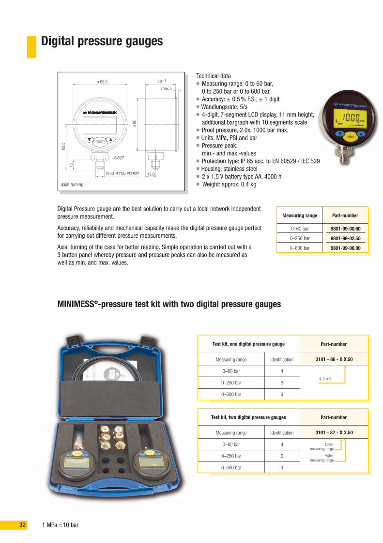
Digital pressure gauges
0–60 bar
0–250 bar
0–600 bar
Measuring range
9801-99-00.60
9801-99-02.50
9801-99-06.00
Part-number
Technical data� Measuring range: 0 to 60 bar,0 to 250 bar or 0 to 600 bar
� Accuracy: ± 0,5% F.S., ± 1 digit� Wandlungsrate: 5/s� 4-digit, 7-segment LCD display, 11 mm height,additional bargraph with 10 segments scale
� Proof pressure, 2.0x, 1000 bar max.� Units: MPa, PSI and bar� Pressure peak:min.- and max.-values
� Protection type: IP 65 acc. to EN 60529 / IEC 529� Housing: stainless steel� 2 x 1,5 V battery type AA, 4000 h� Weight: approx. 0,4 kg
Digital Pressure gauge are the best solution to carry out a local network independentpressure measurement.
Accuracy, reliability and mechanical capacity make the digital pressure gauge perfectfor carrying out different pressure measurements.
Axial turning of the case for better reading. Simple operation is carried out with a3 button panel whereby pressure and pressure peaks can also be measured aswell as min. and max. values.
MINIMESS®-pressure test kit with two digital pressure gauges
3101 - 86 - 0 X.50
Part-number
Measuring range
0–60 bar
0–250 bar
0–600 bar
Test kit, one digital pressure gauge
Identification
4
6
9
4, 6 or 9
3101 - 87 - X X.50
Part-numberTest kit, two digital pressure gauges
Identification
4
6
9
Lowermeasuring range
Highermeasuring range
axial turning
SW27
ø 83,5 46
max 5
ø80
15,8
15
69,5
G1/4 B DIN EN 837
+1
MENU
Measuring range
0–60 bar
0–250 bar
0–600 bar

331 MPa =10 bar
Analogue pressure gauges
256
138
21ø6
2
ø68,
5ISO 228-G1/4 B
EN 837-1
psibar
Display range
9802-01-00.10
9802-01-00.16
9802-01-00.25
9802-01-00.40
9802-01-00.60
9802-01-01.00
9802-01-01.60
9802-01-02.50
9802-01-04.00
9802-01-06.00
Part-number
0 –10 bar (0 –145 psi)
0 –16 bar (0 –230 psi)
0 –25 bar (0 –360 psi)
0 –40 bar (0 – 580 psi)
0 – 60 bar (0 –870 psi)
0 –100 bar (0 –1450 psi)
0 –160 bar (0 –2300 psi)
0 –250 bar (0 –3600 psi)
0 –400 bar (0 –5800 psi)
0 – 600 bar (0 –8700 psi)
� Housing ø 63 mm/Stainless steel� Accuracy 1,6% of end value� Display range in bar and psi� Glycerine filled
Part-number
Identification
0
1
2
3
4
5
6
7
8
9
Measuring range
0 –10 bar (0 –145 psi)
0 –16 bar (0 –230 psi)
0 –25 bar (0 –360 psi)
0 –40 bar (0 –580 psi)
0 – 60 bar (0 –870 psi)
0 –100 bar (0 –1450 psi)
0 –160 bar (0 –2300 psi)
0 –250 bar (0 –3600 psi)
0 –400 bar (0 –5800 psi)
0 – 600 bar (0 –8700 psi)
Test kit with 1 digital pressure gauge
Test kit with 2 digital pressure gauges
MINIMESS®-pressure test kit for series 1215 When ordering, please exchange end digits to 30
MINIMESS®-pressure test kit for series 1615 When ordering, please exchange end digits to 40
30
40
Ø 631,6%
3101 - 14 - X X.50
3101 - 13 - 0 X.50
MINIMESS®-1620 pressure test kit with two analogue pressure gauges
Connection accor-ding to DIN EN 837-1 and EN 837-3
Smallermeasuring range
Largermeasuring range
Requestedmeasuring range
34 1 MPa =10 bar
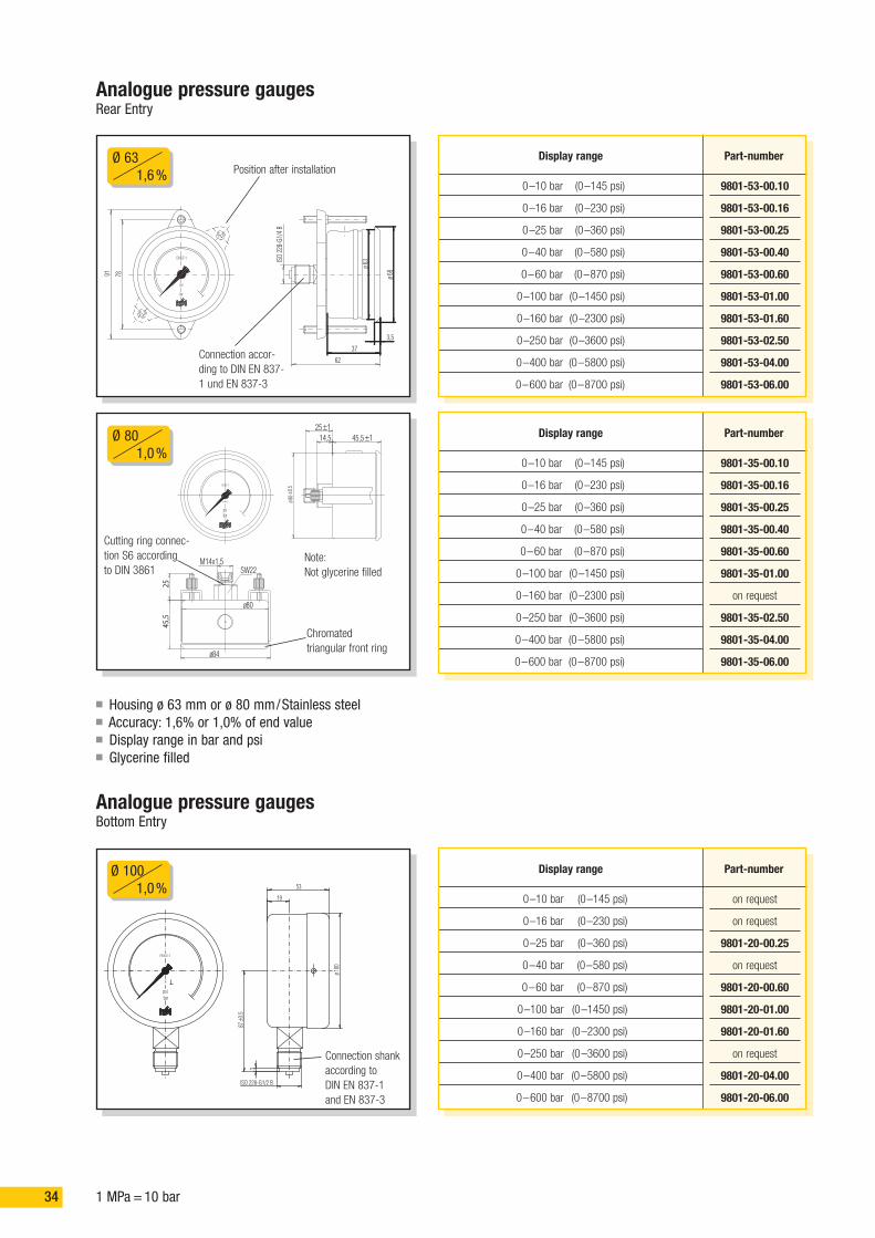
Analogue pressure gaugesRear Entry
� Housing ø 63 mm or ø 80 mm/Stainless steel� Accuracy: 1,6% or 1,0% of end value� Display range in bar and psi� Glycerine filled
bar
psi
EN 837-1
91 78 68ø
63ø
3,5
37
62
ISO
228-
G1/4
B
Display range
9801-53-00.10
9801-53-00.16
9801-53-00.25
9801-53-00.40
9801-53-00.60
9801-53-01.00
9801-53-01.60
9801-53-02.50
9801-53-04.00
9801-53-06.00
Part-number
0 –10 bar (0 –145 psi)
0 –16 bar (0 –230 psi)
0 –25 bar (0 –360 psi)
0 –40 bar (0 –580 psi)
0 – 60 bar (0 –870 psi)
0 –100 bar (0 –1450 psi)
0 –160 bar (0 –2300 psi)
0 –250 bar (0 –3600 psi)
0 –400 bar (0 –5800 psi)
0 – 600 bar (0 –8700 psi)
SW22
psibar
EN 837-1
M14x1,5
84ø
2545
,5
80ø
25 ±1
80±0
,5ø
45,5 ±114,5 Display range Part-number
0 –10 bar (0 –145 psi)
0 –16 bar (0 –230 psi)
0 –25 bar (0 –360 psi)
0 –40 bar (0 –580 psi)
0 – 60 bar (0 –870 psi)
0 –100 bar (0 –1450 psi)
0 –160 bar (0 –2300 psi)
0 –250 bar (0 –3600 psi)
0 –400 bar (0 –5800 psi)
0 – 600 bar (0 –8700 psi)
9801-35-00.10
9801-35-00.16
9801-35-00.25
9801-35-00.40
9801-35-00.60
9801-35-01.00
on request
9801-35-02.50
9801-35-04.00
9801-35-06.00
barpsi
F
EN 837-1
87±0
.5
3
ISO 228-G1/2 B
100
ø
53
19
Display range Part-number
0 –10 bar (0 –145 psi)
0 –16 bar (0 –230 psi)
0 –25 bar (0 –360 psi)
0 –40 bar (0 –580 psi)
0 – 60 bar (0 –870 psi)
0 –100 bar (0 –1450 psi)
0 –160 bar (0 –2300 psi)
0 –250 bar (0 –3600 psi)
0 –400 bar (0 –5800 psi)
0 – 600 bar (0 –8700 psi)
on request
on request
9801-20-00.25
on request
9801-20-00.60
9801-20-01.00
9801-20-01.60
on request
9801-20-04.00
9801-20-06.00
Analogue pressure gaugesBottom Entry
Ø 631,6%
Ø 801,0%
Ø 1001,0%
Position after installation
Connection accor-ding to DIN EN 837-1 und EN 837-3
Connection shankaccording toDIN EN 837-1and EN 837-3
Cutting ring connec-tion S6 accordingto DIN 3861
Note:Not glycerine filled
Chromatedtriangular front ring
351 MPa =10 bar
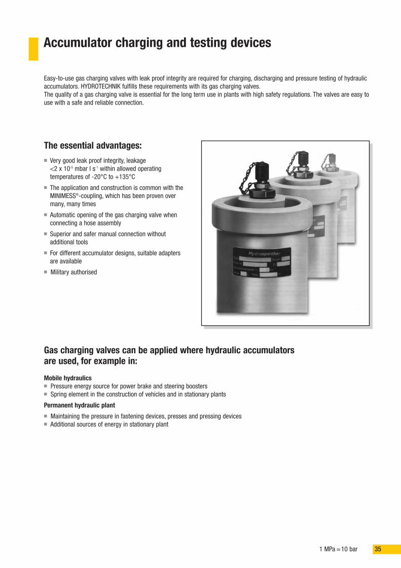
Accumulator charging and testing devices
Easy-to-use gas charging valves with leak proof integrity are required for charging, discharging and pressure testing of hydraulicaccumulators. HYDROTECHNIK fulfills these requirements with its gas charging valves.The quality of a gas charging valve is essential for the long term use in plants with high safety regulations. The valves are easy touse with a safe and reliable connection.
Gas charging valves can be applied where hydraulic accumulatorsare used, for example in:
Mobile hydraulics� Pressure energy source for power brake and steering boosters� Spring element in the construction of vehicles and in stationary plants
Permanent hydraulic plant� Maintaining the pressure in fastening devices, presses and pressing devices� Additional sources of energy in stationary plant
The essential advantages:� Very good leak proof integrity, leakage
<2 x 10⁻⁵ mbar l s-1 within allowed operatingtemperatures of -20°C to +135°C
� The application and construction is common with theMINIMESS®-coupling, which has been proven overmany, many times
� Automatic opening of the gas charging valve whenconnecting a hose assembly
� Superior and safer manual connection withoutadditional tools
� For different accumulator designs, suitable adaptersare available
� Military authorised

36 1 MPa =10 bar
MINIMESS®-gas charging valve 1615Maximum working pressure 63 MPa
M 12 x 1,5
M 14 x 1,5
ISO 228-G 1/4
30
40
40
36,5
36,5
36,5
8,5
10
10
Form F 63 MPa
TorqueinNm Technical data
Part-numberwith FKM sealings
Execu-tion:Metalcap
2402-01-13.50
2402-01-14.00
2402-01-18.00
17
19
19
Hi
G
SW
20ø
Screw-cap thread:M 16 x 1,5
p max Hin mm
iin mm
SWin mm
-20 °C bis +135 °C
Operating temperature rangeThreadG
Type of sealingA
Compatible with the following mediaInert gases, nitrogen and compressed air. Resistant against antifreeze, oil,anti corrosion oil, grease and fuel.
Recorded with inspection certificate 3.1 B in accordance to DIN EN 10204, certificate 2.2. in accordance to DIN EN 10204
1.4571
1.4104
Couplingmaterial
M 14 x 1,5 40 36,5 10Form B 63 MPa 2402-01-49.7019 -33 °C bis +135 °C 1.4104
MaterialBody: 1.4104 (C4)Pressure spring: 1.4310Screw cap: brass (blackened)
Attention: Before using oxygen, please ensure you rinse and clean the gas charging valve.
SealingInternal primary and secondary sealing as well as integral seat sealand anti vibration O-ring (to prevent loosening of the metal cap) madeof Viton.
Adapter incorporating gas charging valve 1615 made of stainless steel
SW30
Hi
G
20ø
63 MPa 1.410430
36
Type of hydraulicaccumulator
7/8“-14 UNF
M 28 x 1,5
Bosch-bubble accumul.
Bosch-diaphragm accumul.
p max Material
73
63
Hin mm
36
26
Iin mm
SWin mm
2446-16-30.00
2446-18-30.00
Part-numberwith FKM - sealing
Thread ofaccumulator
Gas charging valve adapter 1615To be directly screwed on the original valve of the accumulator
H
25ø
G
16M x1,5
63 MPa 1.0718
Type of hydraulicaccumulator
VG 8 DIN 7756
5/16“-32 UNEF
Langen
US
p max Material
32
32
Hin mm
5414-02-00.00
5414-02-10.00
Part-numberwith FKM - sealing
Thread ofaccumulator
Surface protection: galvanized and chromated. Further screw-in threads on request.

37
Accumulator charging and testing devices
0–400 bar
0–250 bar
Pressure gaugedisplay range
MINIMESS® 1615
MINIMESS® 1620
Measuring connection
W 24,32 x 1/14“
W 24,32 x 1/14“
Cylinder connectionthread G
124
124
Hin mm
123
123
Lin mm
28
28
SWin mm
5114-01-00.10
5114-21-03.00
Part-number
� Charging of the hydraulic accumulator� Testing and lowering the pressure within the hydraulic accumulator� Pressure gauge Cl. 1,6 - Ø 63 mm
Complete measuring equipment kit on request.
1,0–235 bar
1,0–235 bar
Secondaryadjustment
0–250 bar
0–250 bar
Pressure gauge dis-play range, secondary
W 24,32 x 1/14“
W 21,8 x 1/14“
Cylinder connectionthread G
MINIMESS® 1615
MINIMESS® 1615
Connectionsecondary
28
28
SWin mm
5401-02-00.00
5401-02-02.00
Part-number
� Filling, adjusting and controlling gas pressure in hydraulic accumulators with nitrogen filling� Pressure gauge Cl. 1,6 - Ø 63 mm� Pressure gauge for primary pressure display 0 to 400 bar
Complete measuring equipment kit on request.
0–1,3 bar
Secondaryadjustment
0–1,6 bar
Pressure gauge dis-play range, secondary
W 24,32 x 1/14“
Cylinder connectionthread G
MINIMESS® 1615
Connectionsecondary
28
SWin mm
5401-07-00.00
5401-07-00.10
Part-number
� Pre-adjustment of the flushing- and charging pressure� Flushing and charging of nitrogen systems� Pressure gauge Cl. 1,6 - Ø 63 mm� Pressure gauge for primary pressure display 0 to 250 bar
Gas charging and testing device with pressure reducer valve
Gas charging and flushing device with pressure reducer valvefor low pressure
Complete measuring equipment with transport case and high pressure hose
1 MPa =10 bar

Compatibility table
� Sealing material: Viton� Free-cutting steel 1.0718 (9SMnPb28K), gradually change over to chrome (VI)-free surface treatment� Corrosion-resistant stainless steel 1.4104 (X 12CrMoS 17)� Acid proof stainless steel 1.4571 (X 10CrNiMoTi 1810) antimagnetic� Hoses: polyamide 11
All statements are not binding and are only for your information
Explanations:1 = good, absolute resistance without modifications2 = limited, resistance depends on using time and operating conditions3 = not recommended - material is affected and the mechanical characteristics are decreased4 = slight diffusion when using gases; can only be used as a test- and filling hose. For permanent use,
we recommend our measuring tubes made of stainless steel5 = the transparent material can change the colour6 = slight swelling, but no modifications of the mechanical characteristics
If your medium of application is not mentioned, please get in contact with us.
Flow rate media
Acetone
Ethyl alcohol, pure
Ammonia, concentrated
Ammonia, liquid
Formic acid
Gasoline, pure
Benzene
Brake fluid
Butane
Cyclohexane
Diesel motor fuel
Freon 12
Glycerin, pure
Glycols
Heating oil
Hydraulic fluid (mineral oil base)
Kerosene
Carbon dioxide
Methane
Methyl alcohol, pure
Mineral oils
Petroleum
Polyalkyleneglycol (HEPG)
Propane
Oxygen
Lubricating oils and grease
Soap solution
Nitrogen
Synthetic esters (HEES)
Essence of turpentine
Tetra chloromethane
Toluene
Trichloroethylene
Triglycerides (HETG)
Water
Sea water
Sealing
3 *)
1/2
3 *)
3 *)
3 *)
1
1/2
3 *)
1
1
1
1/2
1/2
1/2
1
1
1
1
1
3 *)
1
1
2 (<100 °C)
1
1
1
1
1
2 (<100 °C)
1
1
1/2
1/2
2 (<80 °C)
1
1
1.0718
1
1
1
1
3
1
1
1
2
1
1
1
1
1
1
1
1
3
2
1
1
1
2
2
3
1
3
1
1
2
2
2
1
1
3
3
1.4104
2
1
1
1
2
1
1
1
1
1
1
1
1
1
1
1
1
1
1
1
1
1
1
1
1
1
1
1
1
1
1
1
1
1
1
3
1.4571
1
1
1
1
1
1
1
1
1
1
1
1
1
1
1
1
1
1
1
1
1
1
1
1
1
1
1
1
1
1
1
1
1
1
1
2
20 °C
1/5
1/6
1
1
3
1
1
1
1
1
1
1
1
1
1
1
1
1/4
1/4
1/6
1
1
1
1/4
1/4
1
1
1/4
1
1
1
1
2
1
1
1
40 °C
1/6
2
1
1
3
1
1/6
1
1
1
1
1
1
1
1
1
1
1/4
1/4
2
1
1
1
1/4
1/4
1
1
1/4
1
1
3
1/6
3
1
1
1
60 °C
2
3
1
3
1/6
2
1
1
2
1
1
2
2
1
1
1/6
1/4
1/4
3
1
1/6
2/4
1/4
2/4
1
1
1/4
2/4
1/6
2
2/4
1
1
90 °C
3
1
2
2
1
1
3
3
1
1
1
3/4
3/4
1
1
3/4
2
3/4
1
1
Fittings / Material Hoses
*) Application of suitable sealing materials on request.
38
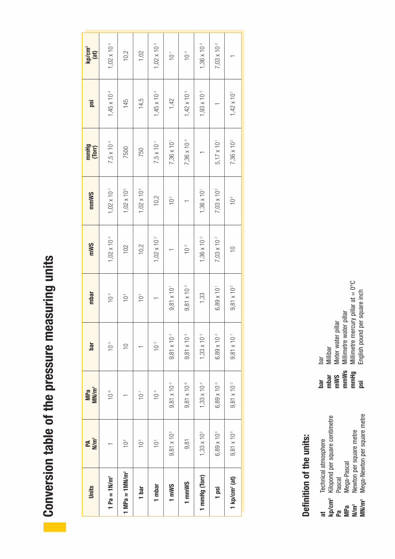
1Pa=1N/m
2
1MPa=1MN/m
2
1bar
1mbar
1mWS
1mmWS
1mmHg(Torr)
1psi
1kp/cm
2(at)
1 106
105
102
9,81
x10
3
9,81
1,33
x10
2
6,89
x10
3
9,81
x10
4
PA N/m
2Units
10-6 1 10-1
10-4
9,81
x10
-3
9,81
x10
-6
1,33
x10
-4
6,89
x10
-3
9,81
x10
-2
MPa
MN/m
2
10-5
10 1 10-3
9,81
x10
-2
9,81
x10
-5
1,33
x10
-3
6,89
x10
-2
9,81
x10
-1
bar
10-2
104
103
1
9,81
x10
1
9,81
x10
-2
1,33
6,89
x10
1
9,81
x10
2
mbar
1,02
x10
-4
102
10,2
1,02
x10
-2
1 10-3
1,36
x10
-2
7,03
x10
-1
10mWS
1,02
x10
-1
1,02
x10
5
1,02
x10
4
10,2
103
1
1,36
x10
1
7,03
x10
2
104
mmWS
7,5
x10
-3
7500
750
7,5
x10
-1
7,36
x10
1
7,36
x10
-2
1
5,17
x10
1
7,36
x10
2
mmHg
(Torr)
1,45
x10
-4
145
14,5
1,45
x10
-2
1,42
1,42
x10
-3
1,93
x10
-2
1
1,42
x10
1
psi
1,02
x10
-5
10,2
1,02
1,02
x10
-3
10-1
10-4
1,36
x10
-3
7,03
x10
-2
1
kp/cm
2
(at)
Conversiontableofthepressuremeasuringunits
Definitionoftheunits:
atTech
nicala
tmosph
ere
kp/cm
2Kilopo
ndpe
rsqu
arecentim
etre
PaPa
scal
MPa
Meg
a-Pa
scal
N/m
2Ne
wtonpe
rsqu
aremetre
MN/m
2Meg
a-Ne
wtonpe
rsqu
aremetre
bar
bar
mbar
Millibar
mWS
Meter
water
pillar
mmWs
Millim
etre
water
pillar
mmHg
Millim
etre
mercu
rypillara
t=0°C
psi
Englishpo
undpe
rsqu
areinch

HYDROTECHNIK GmbHHolzheimer Straße 94 –96 | 65549 Limburg
Tel. 0 64 31.40 04-0 | Fax 0 64 31.4 53 08www.hydrotechnik.com | [email protected]
8898-01-00.71/2007