hygrolog hl-nt data logger instruction manual
TRANSCRIPT

IN-E-HL-NT-V2_11 Rotronic AG Bassersdorf, Switzerland
Document code Unit
HygroLog HL-NT data logger: instruction manual
Instruction Manual Document Ty pe
Page 1 of 48 Document title
© 2009-2010; Rotronic AG IN-E-HL-NT-V2_11
HygroLog HL-NT Data Logger
Instruction Manual
IN-E-HL-NT-V2_11 Rotronic AG Bassersdorf, Switzerland
Document code Unit
HygroLog HL-NT data logger: instruction manual
Instruction Manual Document Ty pe
Page 2 of 48 Document title
© 2009-2010; Rotronic AG IN-E-HL-NT-V2_11
Table of contents: 1. Overview ........................................................................................................................3 1.1 General .......................................................................................................................3 1.2 Compatibility with previous models of probes and docking stations .................................4 2. General description of the HygroLog HL-NT ..................................................................5 2.1 Models ........................................................................................................................5 2.2 Required accessories...................................................................................................5 2.3 HygroLog HL-NT inputs................................................................................................5 2.4 Power supply ...............................................................................................................8 2.5 Memory card ...............................................................................................................9 2.6 LED Indicators ...........................................................................................................10 2.7 Beeper ......................................................................................................................10 2.8 HygroLog HL-NT functions .........................................................................................10 2.9 HygroClip 2 probe functions .......................................................................................13 2.10 Event tracking ...........................................................................................................14 2.11 Operating limits (electronics only) ...............................................................................16 3. Docking stations for the HygroLog HL-NT ...................................................................17 3.1 Models ......................................................................................................................17 3.2 Installation.................................................................................................................20 3.3 Docking station inputs ................................................................................................25 3.4 Relay contacts ...........................................................................................................26 4. Pin-out diagrams..........................................................................................................26 5. HW4 software ...............................................................................................................28 5.1 Computer/Operating System Requirements .................................................................28 5.2 Operating System Compatibility ..................................................................................29 5.3 Settings and functions accessible only with HW4 .........................................................29 6. ERES regulatory compliance .......................................................................................30 7. Getting started .............................................................................................................31 8. Stand-alone operation..................................................................................................31 8.1 Operating modes .......................................................................................................31 8.2 Display and keypad....................................................................................................31 8.3 Display modes ...........................................................................................................33 8.4 Settings and functions accessible from the Keypad ......................................................33 8.5 Internal function menu (models with display and keypad) .............................................34 9. Operation on a network................................................................................................37 9.1 Baud rate and communications protocol compatibility requirements ..............................37 9.2 Ethernet local area network ........................................................................................37 9.3 RS-485 multi-drop network .........................................................................................38 9.4 General wiring guidelines ...........................................................................................39 9.5 Guidelines for RS-485 wiring ......................................................................................40 10. HygroClip probe adjustment procedures.................................................................41 10.1 Single Point adjustment ..............................................................................................41 10.2 Multi-Point adjustment ................................................................................................42 11. Warnings and useful tips .........................................................................................42 12. Communications protocol .......................................................................................43 13. Firmware updates ....................................................................................................43 14. Specifications ..........................................................................................................44 15. Accessories .............................................................................................................47 16. Supporting documents ............................................................................................47 17. Document releases ..................................................................................................48
IN-E-HL-NT-V2_11 Rotronic AG Bassersdorf, Switzerland
Document code Unit
HygroLog HL-NT data logger: instruction manual
Instruction Manual Document Ty pe
Page 3 of 48 Document title
© 2009-2010; Rotronic AG IN-E-HL-NT-V2_11
Applicability: This manual is valid for instruments with firmware version 2.0x (see MENU - Instrument or check using the ROTRONIC HW4 software, Device Manager). Examples: 2.0a, 2.0b. Changes in the last character of the version number reflect minor changes in the internal software of the instrument that do not affect the manner in which the instrument should be operated.
1. Overview
1.1 General HygroLog HL-NT is a series of networkable data loggers primarily designed for use with the HygroClip 2 digital humidity-temperature probes. Depending on the model and options, the HygroLog HL-NT main features are as follows:
o Internal probe input: allows installing a HC2-S humidity-temperature probe internally to prevent unauthorized removal. This input can also be connected to an external probe by means of an extension cable.
o Inputs for up to 6 additional external probes, including analog probes and 4-wire passive RTD probes.
o Monitoring of up to two external contacts (relay output, door, etc.). o Large recording capacity with removable flash memory card. Up to 750,000 values can
be recorded with the standard 16 MB card. Cards with a capacity of up to 1 GB are available.
o Display with backlight and keypad. This allows the HygroLog HL-NT to operate as a stand-alone unit after initial configuration with the HW4 software.
o Compliance with FDA 21 CFR Part II and GAMP regulations regarding electronic records and electronic signatures (ERES).
o Compatible with Ethernet networks (TCP / IP protocol – LAN or WLAN). o Dedicated RS-485 network of up to 64 HygroLog HL-NT per communication port o Simultaneous data recording and data display either locally or on a PC.
Internal power for both the HygroLog HL-NT and probes is provided by a 9V battery (factory standard) or by a 9V rechargeable battery (user supplied). The HygroLog HL-NT requires a docking station to (a) to power the HygroLog HL-NT with an external AC adapter, (b) to configure the HygroLog HL-NT and communicate with a PC, (c) to connect the HygroLog HL-NT to a network and (d) to mount the HygroLog HL-NT to a wall or to place the HygroLog HL-NT on the optional desk-top stand. The most basic model of docking station simply provides a means of mounting the HygroLog HL-NT to a wall and of powering the HygroLog HL-NT with an external AC adapter. All other models offer the same functionality as the basic model and also provide a communication port (RS232, USB or RJ45 / Ethernet) as well as additional inputs for probes and external contacts. Docking stations with an RS232 or USB port are used to connect the HygroLog HL-NT directly to a PC. Docking stations with an RJ45 connector are used to connect the HygroLog HL-NT to an Ethernet LAN. In both cases, the docking station features an RS485 port that can be used to connect up to 64 HygroLog HL-NT in a multi-dropped arrangement (dedicated RS-485 network). This is useful when the PC does not have an Ethernet network interface card or when the number of available

IN-E-HL-NT-V2_11 Rotronic AG Bassersdorf, Switzerland
Document code Unit
HygroLog HL-NT data logger: instruction manual
Instruction Manual Document Ty pe
Page 4 of 48 Document title
© 2009-2010; Rotronic AG IN-E-HL-NT-V2_11
Ethernet ports is limited. Direct connection to an Ethernet LAN allows, in principle, an unlimited number of HygroLog HL-NT to be put on a network monitored by the HW4 software. HW4 allows any combination of RS-232, USB, Ethernet and RS-485 connections. When equipped with a docking station, the HygroLog HL-NT can be used together with the ROTRONIC HW4 software for Windows based PCs (version 2.3.0 or higher). In addition to providing for the networking of large quantities of data loggers and other instruments, the main functions of HW4 include:
o Configuration of the HygroLog HL-NT and docking station o Programming of the HygroLog HL-NT logging function o Manual or automatic downloading of the data recorded by the HygroLog HL-NT o On-line data monitoring and direct data recording by the PC o Automatic generation of graphs and data tables o Monitoring of the networked instruments and data for alarm conditions o Alarm reporting o Maintenance of audit trails o Calibration and adjustment of the HygroClip 2 probes o Generation of protocols, electronic signatures, etc.
A high level of protection against network failures can be achieved by logging data directly on the PC while also recording the data locally on the HygroLog HL-NT with automatic download to the PC at regular interval of times. Note: Instructions for using the HW4 software are not included in this manual. These instructions are shipped separately on the software CD ROM.
1.2 Compatibility with previous models of probes and docking stations
o The HygroLog HL-NT is designed for use with the HygroClip 2 probes (UART interface) and is not compatible with the previous generation of HygroClip probes (DIO interface).
o Docking stations designed for the previous generation of HygroClip probes (such as DS-
U1, DS-U4, etc.) are not compatible with the HygroLog HL-NT.
o RS-485 drop-down networks: the HygroLog HL-NT is compatible with previous versions of the HygroLog NT and with other legacy products. The HygroLog HL-NT cannot be used in the same RS-485 drop-down as a HF4 or HF5 transmitters or any product that rely on the RO-ASCII communications protocol.
o Unlike previous versions, The HygroLog HL-NT does not have a remote mode
IN-E-HL-NT-V2_11 Rotronic AG Bassersdorf, Switzerland
Document code Unit
HygroLog HL-NT data logger: instruction manual
Instruction Manual Document Ty pe
Page 5 of 48 Document title
© 2009-2010; Rotronic AG IN-E-HL-NT-V2_11
2. General description of the HygroLog HL-NT
2.1 Models Basic models without display and keypad
o HygroLog HL-NT2: logger for plug-in HygroClip 2 probe (probe is not included and must be ordered separately). Probe model HC2-S can be mounted either internally or in the extended position. Other probe models are external and require an extension cable.
o HygroLog HL-NT3: same as HL-NT2 with 2 additional connectors suitable for a HygroClip 2 digital probe.
Models with display and keypad
o HygroLog HL-NT2-D: same probe as HygroLog HL-NT2 o HygroLog HL-NT3-D: same probe / probe inputs as HygroLog HL-NT3
Models with internal HC2-S probe pre-installed
o Models HL-NT2-P, HL-NT2-DP, HL-NT3-P and HL-NT3-DP are supplied with an internal HC2-S probe pre-installed.
2.2 Required accessories ● Models without display/keypad: The following accessories are required in order to be able to use the logger: - Any model of docking station (except model DS-NT1) - Connecting cable docking station to PC - PC with the ROTRONIC HW4 software installed (version 2.3.0 or higher) ● Models with display/keypad: In principle, these models can be used without any accessory. However, accessing all of the product functions and changing some important settings such as the date and time requires the same accessories as for the models without display.
2.3 HygroLog HL-NT inputs
2.3.1 Probe input 1 HygroLog HL-NT2-P, HL-NT2-DP, HL-NT3-P and HL-NT3-DP: these models are supplied with an internal HC2-S plug-in probe. This probe can be either ret racted or extended. The probe can also be separated from the logger with an extension cable, and in this case the HC2-S probe may be replaced with another model of HygroClip 2 probe so as to meet specific application

IN-E-HL-NT-V2_11 Rotronic AG Bassersdorf, Switzerland
Document code Unit
HygroLog HL-NT data logger: instruction manual
Instruction Manual Document Ty pe
Page 6 of 48 Document title
© 2009-2010; Rotronic AG IN-E-HL-NT-V2_11
requirements (see document E-M-HC2 Probes-V1). Open the housing of the HygroLog to change the position of the probe or to install a probe extension cable.
To extend the probe, lift the HygroClip S probe from its position and remove the slotted cap from the HygroLog. To extend the probe, place on the probe the ring supplied with the HygroLog. Insert the ring into the slot in the instrument housing where the slotted cap was. Relocate the probe connector up by one or two ribs. Close the instrument housing. Proceed in a similar manner to install a probe extension cable.
HygroClip S extended position
Extension cable used to separate the probe from
the HygroLog.
Ring (replaces the slotted cap)
To open the housing of the HygroLog, remove the five screws, as indicated by the arrows. The far right drawing shows the HygroClip S probe in the retracted position. The base of the probe is plugged into a connector that is separated from the main board by a length of wire.
Probe connector
The shorter screw goes here
IN-E-HL-NT-V2_11 Rotronic AG Bassersdorf, Switzerland
Document code Unit
HygroLog HL-NT data logger: instruction manual
Instruction Manual Document Ty pe
Page 7 of 48 Document title
© 2009-2010; Rotronic AG IN-E-HL-NT-V2_11
Notes:
o For maximum protection against vandalism, use the HC2-S probe in the retracted position. For a faster response, use the probe in the extended position.
o For additional information on the HygroClip 2 probes see document E-M-HC2 Probes-V1.
2.3.2 Probe inputs 2 and 3 (HygroLog HL-NT3) The HygroLog HL-NT3 can be used with up to 2 additional HygroClip 2 probes. For further information on the HygroClip 2 probes, see document E-M-HC2 Probes-V1.
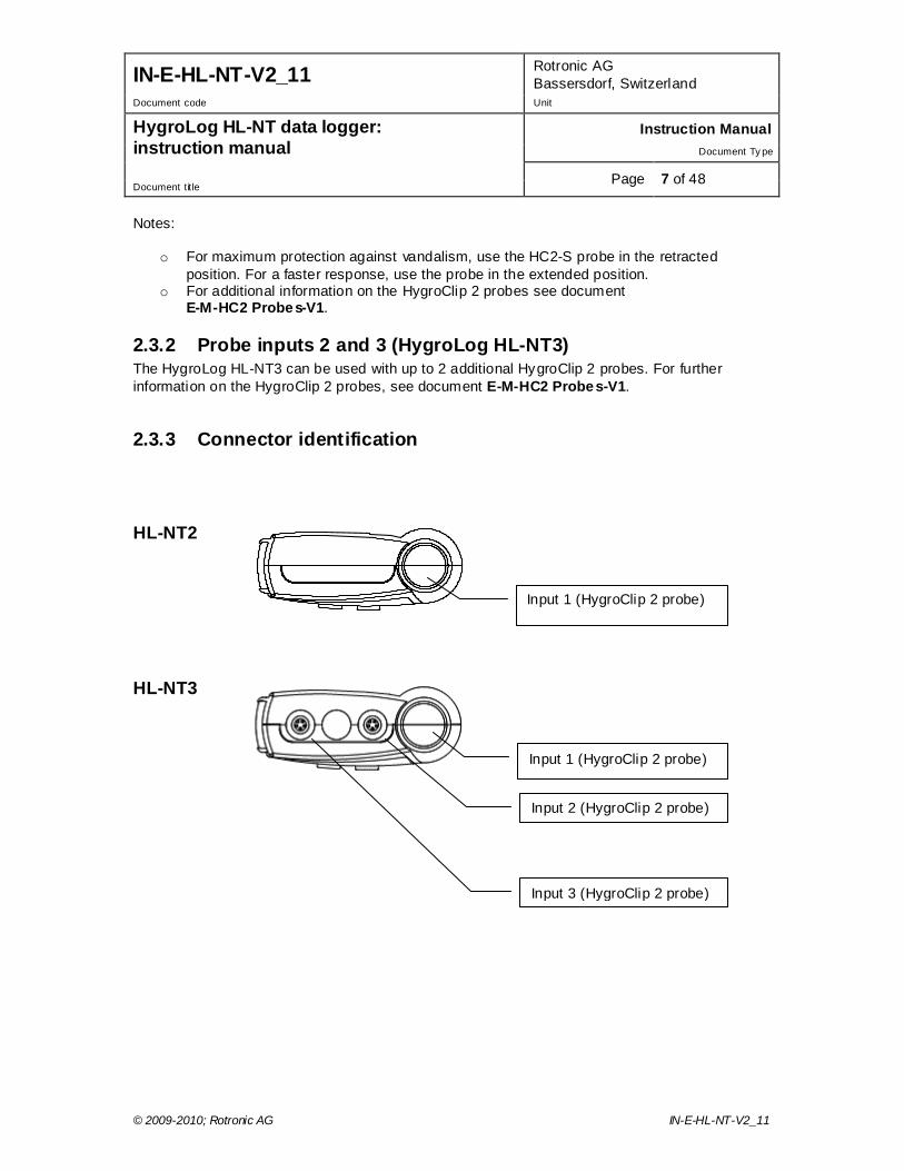
2.3.3 Connector identification
Input 1 (HygroClip 2 probe)
Input 2 (HygroClip 2 probe)
Input 3 (HygroClip 2 probe)
Input 1 (HygroClip 2 probe)
HL-NT2
HL-NT3
IN-E-HL-NT-V2_11 Rotronic AG Bassersdorf, Switzerland
Document code Unit
HygroLog HL-NT data logger: instruction manual
Instruction Manual Document Ty pe
Page 8 of 48 Document title
© 2009-2010; Rotronic AG IN-E-HL-NT-V2_11
2.4 Power supply The HygroLog HL-NT ships with a regular 9V battery which must be inserted first (see battery replacement). To conserve battery power, models with the LC display and keypad are shipped with the Display Sleep function enabled (see Software Functions). When the keypad has not been used for some time, this function automatically turns off the display off. The display can be temporarily activated by pressing on any key of the keypad. When connected to a docking station, the HygroLog HL-NT can be powered with an external AC adapter. Note: most models of docking station require the use of an external AC adapter due to the current consumption of the docking station internal electronics. After reconfiguring the HygroLog HL-NT with the ROTRONIC HW4.software, a rechargeable battery (accumulator) can be used instead of a regular battery. Recharging the battery require a docking station and an external AC adapter. WARNING: Trying to recharge a regular battery is potentially dangerous. Whenever a regular battery is being used, the logger should be configured with the internal battery charge function disabled.
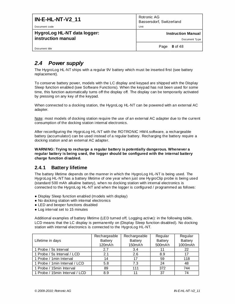
2.4.1 Battery lifetime The battery lifetime depends on the manner in which the HygroLog HL-NT is being used. The HygroLog HL-NT has a battery lifetime of one year when just one HygroClip probe is being used (standard 500 mAh alkaline battery), when no docking station with internal electronics is connected to the HygroLog HL-NT and when the logger is configured / programmed as follows: ● Display Sleep function enabled (models with display) ● No docking station with internal electronics ● LED and beeper functions disabled ● Log interval set to 15 minutes Additional examples of battery lifetime (LED turned off, Logging active): in the following table, LCD means that the LC display is permanently on (Display Sleep function disabled). No docking station with internal electronics is connected to the HygroLog HL-NT. Lifetime in days
Rechargeable Battery
120mAh
Rechargeable Battery
150mAh
Regular Battery
500mAh
Regular Battery
1000mAh 1 Probe / 5s Interval 2.7 3.4 11 22 1 Probe / 5s Interval / LCD 2.1 2.6 8.9 17 1 Probe / 1min Interval 14 17 59 118 1 Probe / 1min Interval / LCD 5.8 7.3 24 48 1 Probe / 15min Interval 89 111 372 744 1 Probe / 15min Interval / LCD 8.9 11 37 74
IN-E-HL-NT-V2_11 Rotronic AG Bassersdorf, Switzerland
Document code Unit
HygroLog HL-NT data logger: instruction manual
Instruction Manual Document Ty pe
Page 9 of 48 Document title
© 2009-2010; Rotronic AG IN-E-HL-NT-V2_11
Note: the consumption of the display is negligible when the Display Sleep function is enabled. With the display always on, power consumption is at its highest when the display refresh rate is set with HW4 to the minimum of 5 sec. Because of the requirement to keep track of the date and time, the HygroLog HL-NT does not have a power on/off switch. Every minute, both the date and time are recorded to the internal EEPROM. Seconds are not recorded. In the event of a relatively brief interruption of power (such as when replacing the battery), time may fall behind in increments of one minute. Removing the battery for an extended period of time will cause the logger to completely lose track of the date and time.
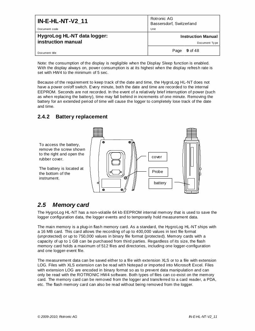
2.4.2 Battery replacement
2.5 Memory card The HygroLog HL-NT has a non-volatile 64 kb EEPROM internal memory that is used to save the logger configuration data, the logger events and to temporarily hold measurement data. The main memory is a plug-in flash memory card. As a standard, the HygroLog HL-NT ships with a 16 MB card. This card allows the recording of up to 400,000 values in text file format (unprotected) or up to 750,000 values in binary file format (protected). Memory cards with a capacity of up to 1 GB can be purchased from third parties. Regardless of its size, the flash memory card holds a maximum of 512 files and directories, including one logger-configuration and one logger-event file. The measurement data can be saved either to a file with extension XLS or to a file with extension LOG. Files with XLS extension can be read with Notepad or imported into Microsoft Excel. Files with extension LOG are encoded in binary format so as to prevent data manipulation and can only be read with the ROTRONIC HW4 software. Both types of files can co-exist on the memory card. The memory card can be removed from the logger and transferred to a card reader, a PDA, etc. The flash memory card can also be read without being removed from the logger.
cover
To access the battery, remove the screw shown to the right and open the rubber cover. The battery is located at the bottom of the instrument.
Probe i t 5 battery
IN-E-HL-NT-V2_11 Rotronic AG Bassersdorf, Switzerland
Document code Unit
HygroLog HL-NT data logger: instruction manual
Instruction Manual Document Ty pe
Page 10 of 48 Document title
© 2009-2010; Rotronic AG IN-E-HL-NT-V2_11
2.6 LED Indicators The HygroLog HL-NT is equipped with a green and red LED. The logger can be configured with HW4 to have the green side of the LED flash when logging is active. The red side of the LED can be made to flash when there is an alarm condition (see note below) and / or when the logger requires attention (low battery, flash memory card full, etc.) In the transient alarm mode, the red LED flashes for only as long as the data from a probe corresponds to an alarm condition. In the durable alarm mode, the red LED stays on even after the alarm condition has disappeared. When the LED is set to provide a durable alarm, it can be reset from the keypad or with HW4.
2.7 Beeper The HygroLog HL-NT is equipped with an internal beeper and can be configured with HW4 to make a clicking sound when any key is being pressed. The beeper can also be configured to emit a 5-second non-repeating sound when there is an alarm condition and / or when the logger requires attention.
2.8 HygroLog HL-NT functions
2.8.1 Calculated parameter Using the HW4 software, the HygroLog HL-NT can be set to compute for each HygroClip probe one of the following psychrometric parameters.
o Dew point (Dp) o Frost point (Fp) o Wet bulb temperature (Tw) o Enthalpy (H) o Vapor concentration (Dv) o Specific humidity (Q) o Mixing ratio by weight (R) o Vapor concentration at saturation (Dvs) o Vapor partial pressure (E) o Vapor saturation pressure (Ew)
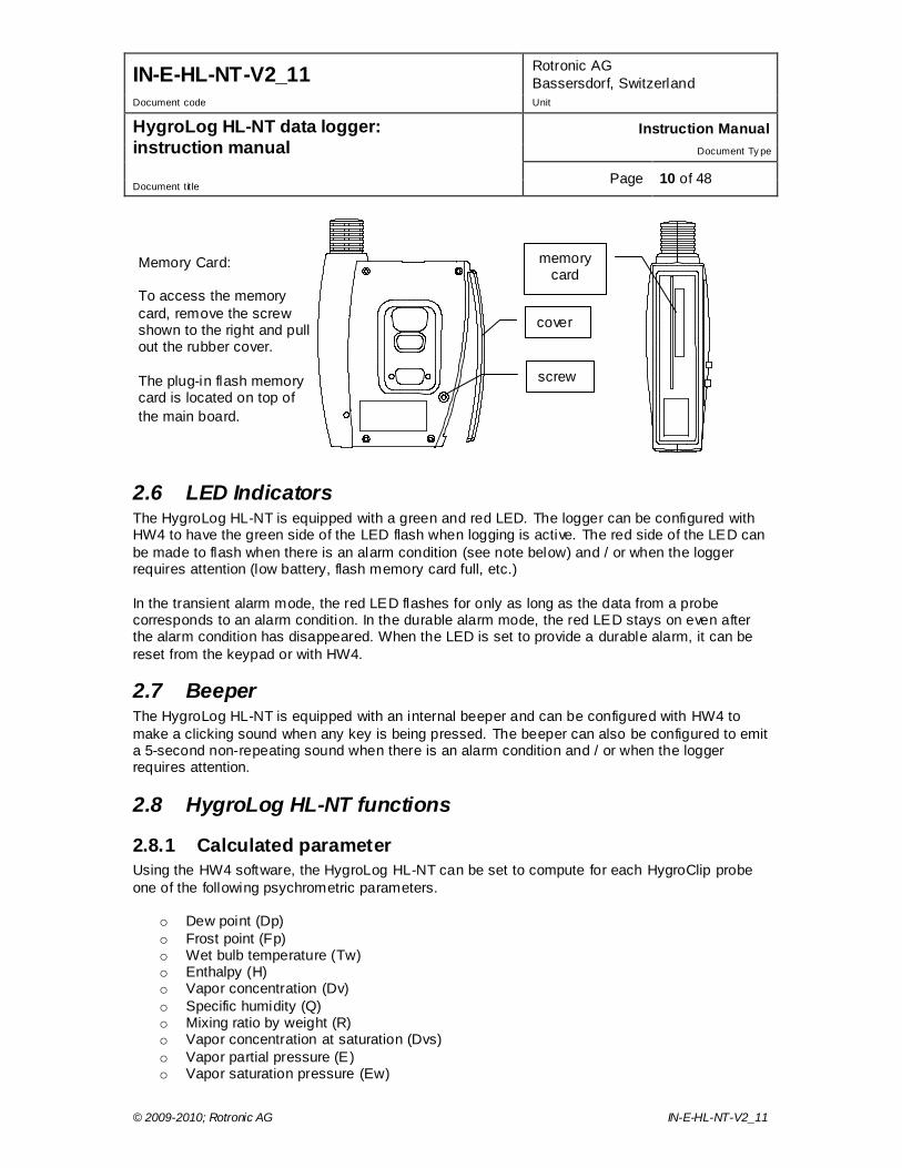
cover
memory card
Memory Card: To access the memory card, remove the screw shown to the right and pull out the rubber cover. The plug-in flash memory card is located on top of the main board.
screw
IN-E-HL-NT-V2_11 Rotronic AG Bassersdorf, Switzerland
Document code Unit
HygroLog HL-NT data logger: instruction manual
Instruction Manual Document Ty pe
Page 11 of 48 Document title
© 2009-2010; Rotronic AG IN-E-HL-NT-V2_11
Each individual probe input can be associated with a different parameter. Note: depending on whether dew point or frost point was selected, both the HygroLog HL-NT and HW4 will display either the symbol Dp or the symbol Fp for values below freezing. The symbol Fp indicates that the value is a frost point as opposed to being a dew point. Regardless of the dew point / frost point selection, the symbol Dp is always displayed for values above freezing. Some of the above parameters require barometric pressure as an input. When an analog pressure probe is connected to one of the HygroLog HL-NT inputs, the logger can be set to use the measurement from this probe. When no pressure probe is being used, a fixed pressure value can be used. This value can be specified as part of the HygroLog HL-NT settings.
2.8.2 Data logging Data logging requires that a flash memory card be inserted inside the logger. Using the HW4 software, log files can be set to one of the following formats: ● HW4 binary format [LOG]: files in this format are encoded and can be opened only with the
ROTRONIC HW4 software. HW4 does not allow any manipulation / alteration of the data and requires a password to log in. Should the file be somehow modified, HW4 will give a warning that the file is not an original.
● Text file format [XLS]: in principle, files in this format can be opened with any text editor and / or
imported into Microsoft Excel. The log file format is a global setting of the flash memory card (changing this setting requires the HW4 software). At any given time, the card records data from all inputs in either one format or the other. Files of different formats can co-exist in the flash memory card. Binary files (protected) use substantially less memory space than text files (unprotected). The logging function is independently activated for each individual input. The HygroLog HL-NT creates a separate file for each input that is to be recorded. Multiple inputs cannot be recorded to the same file. The HygroLog HL-NT automatically generates each file name. A file name consists of 8 digits followed by the extension LOG or XLS. The first 4 digits are the same as the last 4 digits of the logger serial number, the 5th digit is the same as the input number and the last 3 digits are a number between 000 and 999 used to differentiate log files created for the same input. The last number that was created is retained in the non-volatile EEPROM and is updated whenever a new file is created for the input. When the number reaches 999, the next update will reset it to 000. All files are located in the root directory of the flash memory card, including the logger event file and the logger configuration file. Regardless of the memory card capacity, the root directory is limited to a maximum of 250 files. This means that the memory card can hold a maximum of 248 log files, and that a card with this amount of files is considered to be full, even if all the memory has not been used. Using HW4, the following log settings can be defined individually for each input: ● Start date and time ● Stop date and time ● Log interval (minimum 5 seconds)
IN-E-HL-NT-V2_11 Rotronic AG Bassersdorf, Switzerland
Document code Unit
HygroLog HL-NT data logger: instruction manual
Instruction Manual Document Ty pe
Page 12 of 48 Document title
© 2009-2010; Rotronic AG IN-E-HL-NT-V2_11
● Measured values and computed parameter, or any parameter combination ● User custom text (used for the log file header) ● User name, HW4-ID, HW4 Serial Number ● Automatic creation of a new file after 200,000 data points or at the end of each day, week or
month Note: unlimited logging (loop mode logging) is not possible. Logging stops automatically when the flash memory card is full. Prior to logging, the user may use HW4 to check the amount of free memory, and verify that there is enough room available. If the flash memory card is removed when logging is active, the HygroLog HL-NT will stop logging until a new card is inserted. Unless the stop date and time have been reached, logging will start again under the next available file name when a new card is inserted. Warning: removing the memory card while logging is active may result in a corrupted log file and in loss of data. Logging can be started immediately for any individual input from the keypad of the HygroLog HL-NT. A deferred start can only be programmed with the HW4 software. The green LED of the HygroLog HL-NT can be set to flash when the instrument is recording data. To conserve battery power, you may want to do this only when an external power source is being used. Logging can be immediately stopped for any individual input directly from the keypad. With HW4, logging can be stopped either immediately or at a future date and time for any individual input or for all inputs. When logging is ended, the HygroLog HL-NT returns to the measuring mode.
2.8.3 Trend indicators See also: Main operating modes and measurement interval When the trend indicator function is enabled, a symbol appears on the left side of the LC display, on the line corresponding to each measured or calculated value. An up arrow denotes a rising value and a down arrow denotes a decreasing value. Both arrows denote a stable value. The trend of a parameter is evaluated by comparing successive averages made of 6 values each. With the shortest possible measurement interval of 5 seconds, each average covers a time period of 30 seconds and the first indication of a trend is available after one minute. Subsequently, the trend is evaluated and updated every 30 seconds. With a longer measurement interval, each average is computed over a longer period of time (always using 6 values) and the trend is also updated over longer intervals of time. For any measured or calculated parameter, the trend indicator shows a stable condition when the absolute value of the difference between two successive averages is < 0.02.
2.8.4 Alarm function Using the HW4 software, both a high and a low alarm value can be associated with the humidity, temperature and calculated parameter of each probe input, A hysteresis value can also be entered for each parameter. This value is used for both the low and the high alarm conditions.
IN-E-HL-NT-V2_11 Rotronic AG Bassersdorf, Switzerland
Document code Unit
HygroLog HL-NT data logger: instruction manual
Instruction Manual Document Ty pe
Page 13 of 48 Document title
© 2009-2010; Rotronic AG IN-E-HL-NT-V2_11
The HygroLog HL-NT has a red LED which can be set with HW4 to flash whenever the value of any parameter corresponds to an alarm condition. The LED can be set to flash only as long as the alarm condition exits or it can be set to provide a durable alarm and, in this case, it will to keep flashing until the alarm is reset. The HygroLog HL-NT can also be set with HW4 to beep for 5 seconds when there is an alarm condition. The HygroLog HL-NT will beep only once, when the condition occurs. Log files do not record the existence of an alarm condition. However, when the contents of a log file are viewed as a data table with the HW4 software, values that correspond to an alarm condition are printed over a red background, based on the alarm settings that HW4 downloaded from the logger.
2.8.5 Display-Sleep function This function can be enabled and configured only with the HW4 software. Using the Display Sleep function can substantially extend the li fetime of the battery. When the Display Sleep function is active, the LC display of the HygroLog HL-NT stays blank. The Display Sleep function is effective both in the measure and in the record mode. The display of the HygroLog HL-NT can be set to be always on. It can also be set to automatically go blank after 30 seconds, 1, 5, 10 or 20 minutes when no key is being pressed or when there is no communication with a PC. If the HygroClip NT was in the function menu at the time the display goes blank, it automatically exits the menu. The HygroLog suspends the Display Sleep function whenever a key is pressed. The function is also suspended when external power is available or when the logger receives a communication request (for example from a PC 1). When the display comes up again, it shows by default the measurements from the probe that was selected last. 1 When the HygroLog HL-NT is connected by means of a docking station to a PC and HW4 is running, you should use an external AC adapter to power both the HygroLog HL-NT and docking station. HW4 can be set to use a polling interval as short as 5 seconds to interrogate all instruments connected to the PC and this could cause the battery life time to be sharply reduced.
2.9 HygroClip 2 probe functions
2.9.1 Simulator function (validation of the signal transmission): If so desired, transmission of the HC2 probe output signals can be validated by using the probe simulator function. The HW4 software is required to enable and configure this function. When the function is enabled the probe generates digital and analog signals corresponding to values specified by the user.
2.9.2 Sensor failure detection and fail safe mode: The HygroClip 2 probe automatically detects a sensor failure such as a shorted or open sensor. This information is passed to both the HygroLog HL-NT and HW4 software. The optional display of the HygroLog HL-NT will show an alarm message. The HygroClip 2 probe can also be configured with the HW4 software to generate a "safe or readily identifiable" fixed value for humidity and temperature in the event of a shorted or open sensor.
IN-E-HL-NT-V2_11 Rotronic AG Bassersdorf, Switzerland
Document code Unit
HygroLog HL-NT data logger: instruction manual
Instruction Manual Document Ty pe
Page 14 of 48 Document title
© 2009-2010; Rotronic AG IN-E-HL-NT-V2_11
Note: the sensor diagnostics and drift compensation function of the HygroClip 2 probe is not available with the HygroLog HL-NT due to the fact that the probe is powered only briefly during each log or measurement interval.
2.10 Event tracking The HygroLog HL-NT maintains an internal event file with the extension EVT. This function is always enabled. Part of the procedure to ensure conformity to the FDA requirements is to use the HW4 software to disable the MENU key on the HygroLog HL-NT keypad. The MENU key is the only key that can be used to make changes to the HygroLog HL-NT. When this procedure is implemented, the events recorded by the HygroLog HL-NT are the result of an interaction with the HW4 software. When the MENU key is not disabled, a limited number of events are recorded in the logger event file. In this case no entries are made in the logger event file header. The two tables below provide a list of the events tracked by the HygroLog HL-NT. The logger event file is split between the internal memory of the logger (up to 170 events) and the flash memory card (practically unlimited number of events). HW4 offers the possibility of downloading, opening and printing the entire file contents. All past logger events are available to HW4 as long as the flash memory card is not removed from the logger. The serial number of the logger is used as the file name. Example: 1111111111.EVT The logger event file consists of a file header and a file body. The file header provides the following information: o Most recent programming of the log function: programming date and time, user and HW4
product ID o Most recent device configuration: date and time, user and HW4 product ID o Most recent adjustment to the PC date and time: date and time, user and HW4 product ID
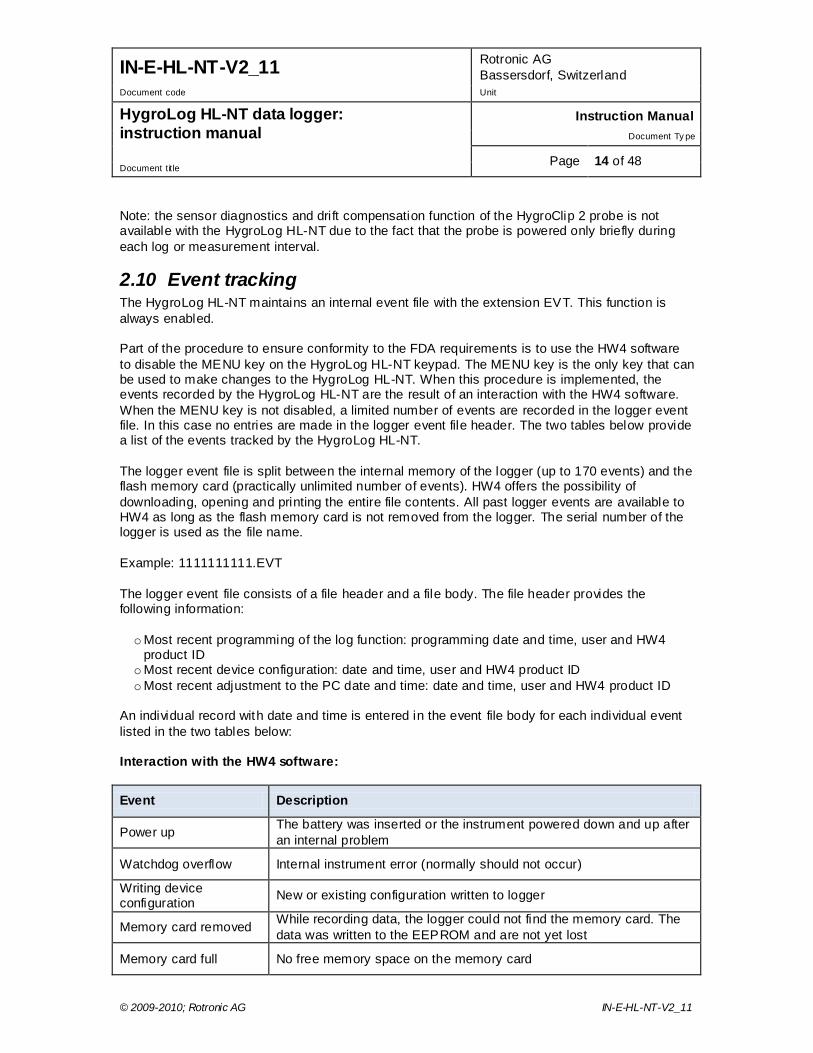
An individual record with date and time is entered in the event file body for each individual event listed in the two tables below: Interaction with the HW4 software:
Event Description
Power up The battery was inserted or the instrument powered down and up after an internal problem
Watchdog overflow Internal instrument error (normally should not occur)
Writing device configuration New or existing configuration written to logger
Memory card removed While recording data, the logger could not find the memory card. The data was written to the EEPROM and are not yet lost
Memory card full No free memory space on the memory card
IN-E-HL-NT-V2_11 Rotronic AG Bassersdorf, Switzerland
Document code Unit
HygroLog HL-NT data logger: instruction manual
Instruction Manual Document Ty pe
Page 15 of 48 Document title
© 2009-2010; Rotronic AG IN-E-HL-NT-V2_11
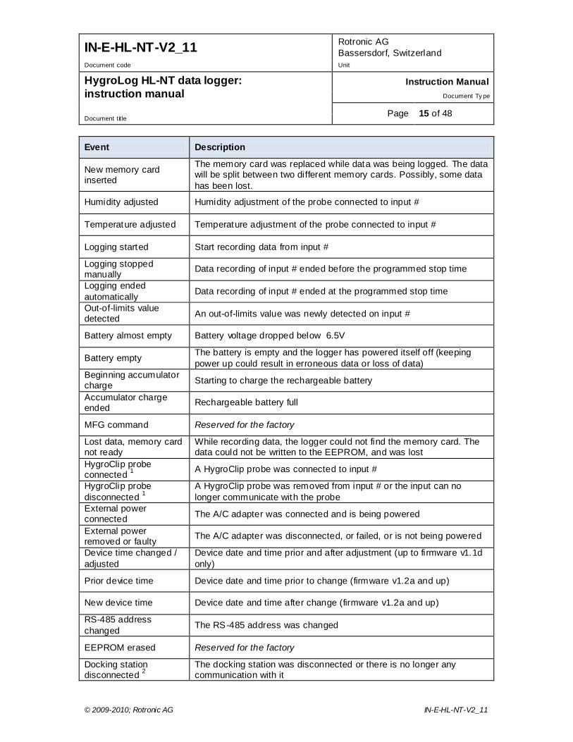
Event Description
New memory card inserted
The memory card was replaced while data was being logged. The data will be split between two different memory cards. Possibly, some data has been lost.
Humidity adjusted Humidity adjustment of the probe connected to input #
Temperature adjusted Temperature adjustment of the probe connected to input #
Logging started Start recording data from input #
Logging stopped manually Data recording of input # ended before the programmed stop time
Logging ended automatically Data recording of input # ended at the programmed stop time
Out-of-limits value detected An out-of-limits value was newly detected on input #
Battery almost empty Battery voltage dropped below 6.5V
Battery empty The battery is empty and the logger has powered itself off (keeping power up could result in erroneous data or loss of data)
Beginning accumulator charge Starting to charge the rechargeable battery
Accumulator charge ended Rechargeable battery full
MFG command Reserved for the factory
Lost data, memory card not ready
While recording data, the logger could not find the memory card. The data could not be written to the EEPROM, and was lost
HygroClip probe connected 1 A HygroClip probe was connected to input #
HygroClip probe disconnected 1
A HygroClip probe was removed from input # or the input can no longer communicate with the probe
External power connected The A/C adapter was connected and is being powered
External power removed or faulty The A/C adapter was disconnected, or failed, or is not being powered
Device time changed / adjusted
Device date and time prior and after adjustment (up to firmware v1.1d only)
Prior device time Device date and time prior to change (firmware v1.2a and up)
New device time Device date and time after change (firmware v1.2a and up)
RS-485 address changed The RS-485 address was changed
EEPROM erased Reserved for the factory
Docking station disconnected 2
The docking station was disconnected or there is no longer any communication with it

IN-E-HL-NT-V2_11 Rotronic AG Bassersdorf, Switzerland
Document code Unit
HygroLog HL-NT data logger: instruction manual
Instruction Manual Document Ty pe
Page 16 of 48 Document title
© 2009-2010; Rotronic AG IN-E-HL-NT-V2_11
Event Description
Docking station connected 2 A docking station was connected and communication was established
Logger language file downloaded
A different internal language file was loaded or the same file was loaded again
Log function programmed The log function has been programmed for input #
Event file deleted Reserved for the factory
1 connection / removal of analog probes is not recorded 2 only when the docking station has internal electronics Events triggered from the keypad:
Event Description
Humidity adjusted Humidity adjustment of the probe connected to input #
Temperature adjusted Temperature adjustment of the probe connected to input #
Logging started Start recording data from input #
Logging stopped manually Data recording of input # ended before the programmed stop time
Prior device time Device date and time prior to change (firmware v1.2a and up)
New device time Device date and time after change (firmware v1.2a and up)
Log function programmed The log function has been programmed for input #
2.11 Operating limits (electronics only) Models without display: ● -10…50°C with the factory supplied alkaline battery ● -30…70°C with a lithium battery or an external AC adapter Models with display: ● -10…50°C with the factory supplied alkaline battery ● -10…60°C with a lithium battery or an external AC adapter The HygroClip probes have generally wider operating limits (see individual probe specifications).
IN-E-HL-NT-V2_11 Rotronic AG Bassersdorf, Switzerland
Document code Unit
HygroLog HL-NT data logger: instruction manual
Instruction Manual Document Ty pe
Page 17 of 48 Document title
© 2009-2010; Rotronic AG IN-E-HL-NT-V2_11
3. Docking stations for the HygroLog HL-NT The HygroLog HL-NT requires a docking station with the appropriate interface to be able to communicate with a PC with the ROTRONIC HW4 software installed. The connector located on the back of the HygroLog HL-NT is meant to be used with one of the available docking stations (UART interface). When installed on a PC, the ROTRONIC HW4 software is used to configure the HygroLog HL-NT, to program its logging function, to download the recorded data and to adjust the probes connected to the logger against a reference environment. A docking station is required for any of the following:
o Mount the HygroLog HL-NT to a wall o Place the HygroLog on the optional desk-top stand o Use an external AC adapter to power the HygroLog HL-NT o Connect the HygroLog HL-NT to a PC: RS232 or USB port, Ethernet (TCP/IP) LAN
or WLAN o Connect up to 64 HygroLog HL-NT or other devices together in a multi-dropped network
(RS-485) Depending on the model, using a docking station also adds functionality to the HygroLog HL-NT:
o Up to 4 additional probes, including analog probes and direct 4-wire RTDs o Logical inputs (external contacts) o Relay outputs
Note: docking stations with internal electronics and PC interface should be generally used with an external AC adapter.
3.1 Models All models of docking station have the same physical dimensions and can be used either as a mechanical adapter to place the HygroLog HL-NT on the optional desk-top stand or as a bracket to mount the HygroLog HL-NT to a wall. Docking stations are available in the following configurations:
3.1.1 Basic docking stations (no digital interface)
o HL-DS-NT0: basic docking station without internal electronics. This model simply provides a means of mounting the HygroLog HL-NT to a wall
o HL-DS-NT1: basic docking station without internal electronics (similar to model HL-DS-
NT0). This model simply provides a receptacle for an AC adapter used to power the HygroLog HL-NT
3.1.2 Docking stations with RS-232 serial interface
o HL-DS-NT2: receptacle for AC adapter, one serial port (RS232) and one RS485 port (multi-drop).
IN-E-HL-NT-V2_11 Rotronic AG Bassersdorf, Switzerland
Document code Unit
HygroLog HL-NT data logger: instruction manual
Instruction Manual Document Ty pe
Page 18 of 48 Document title
© 2009-2010; Rotronic AG IN-E-HL-NT-V2_11
o HL-DS-U1: receptacle for AC adapter, one serial (RS232) port, one RS485 port (multi-drop), four probe inputs (HygroClip 2 or analog probe with voltage output signal), one connector for up to two logical input signals.
3.1.3 Docking stations with USB interface
o HL-DS-NT3: receptacle for AC adapter, one USB port and one RS485 port (multi-drop).
o HL-DS-U2: receptacle for AC adapter, one USB port, one RS485 port (multi-drop), four probe inputs (HygroClip or analog probe with voltage output signal), one connector for up to two logical input signals.
o HL-DS-U2-420: same as HL-DS-U2 but designed for analog probes with a 4-20 mA output signal. Each probe input uses an internal 150 Ohm resistor to convert 4…20 mA to 600…3000 mV (nominal).
o HL-DS-PT2: receptacle for AC adapter, one USB port, one RS485 port (multi-drop
networking), four connectors for RTD probe (direct 4-wire connection), one connector for up to two logical input signals.
o HL-DS-R1: receptacle for AC adapter, one USB port, one RS485 port (multi-drop networking), one connector for up to two logical input signals and two independent relay output connectors.
3.1.4 Docking stations with wired Ethernet interface Note: with any of the following models, use an extension cable to separate all probes from either the HygroLog HL-NT or docking station so as to avoid measurement errors due to self-heating by the docking station.
o HL-DS-NT4: receptacle for AC adapter, one RJ45 connector (Ethernet), one RS485 port (multi-drop) and one connector for up to two logical input signals.
o HL-DS-NT4-WEB: same as HL-DS-NT4 but with an internal web server that can be accessed with a web browser.
o HL-DS-U4: receptacle for AC adapter, one RJ45 connector (Ethernet), one RS485 port (multi-drop), four probe inputs (HygroClip or analog probe with voltage output signal), one connector for up to two logical input signals.
o HL-DS-U4-WEB: same as HL-DS-U4 but with an internal web server that can be accessed with a web browser.
o HL-DS-U4-420: same as HL-DS-U4 but designed for analog probes with a 4-20 mA
output signal. Each probe input uses an internal 150 Ohm resistor to convert 4…20 mA to 600…3000 mV (nominal).
o HL-DS-U4-420-WEB: same as HL-DS-U4-420 but with an internal web server that can be accessed with a web browser.
IN-E-HL-NT-V2_11 Rotronic AG Bassersdorf, Switzerland
Document code Unit
HygroLog HL-NT data logger: instruction manual
Instruction Manual Document Ty pe
Page 19 of 48 Document title
© 2009-2010; Rotronic AG IN-E-HL-NT-V2_11
o HL-DS-PT4: receptacle for AC adapter, one RJ45 connector (Ethernet), one RS485 port
(multi-drop networking), two connectors for RTD probe (direct 4-wire connection), one connector for up to two logical input signals.
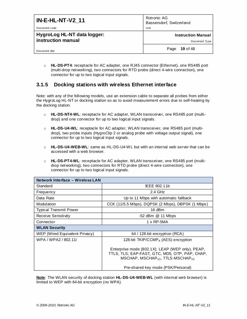
3.1.5 Docking stations with wireless Ethernet interface Note: with any of the following models, use an extension cable to separate all probes from either the HygroLog HL-NT or docking station so as to avoid measurement errors due to self-heating by the docking station.
o HL-DS-NT4-WL: receptacle for AC adapter, WLAN transceiver, one RS485 port (multi-drop) and one connector for up to two logical input signals.
o HL-DS-U4-WL: receptacle for AC adapter, WLAN transceiver, one RS485 port (multi-
drop), two probe inputs (HygroClip 2 or analog probe with voltage output signal), one connector for up to two logical input signals.
o HL-DS-U4-WEB-WL: same as HL-DS-U4-WL but with an internal web server that can be accessed with a web browser.
o HL-DS-PT4-WL: receptacle for AC adapter, WLAN transceiver, one RS485 port (multi-
drop networking), two connectors for RTD probe (direct 4-wire connection), one connector for up to two logical input signals.
Network Interface – Wireless LAN Standard IEEE 802.11b Frequency 2.4 GHz Data Rate Up to 11 Mbps with automatic fallback Modulation CCK (11/5.5 Mbps), DQPSK (2 Mbps), DBPSK (1 Mbps) Typical Transmit Power 16 dBm Receive Sensitivity -52 dBm @ 11 Mbps Connector 1 x RP-5MA WLAN Security WEP (Wired Equivalent Privacy) 64 / 128-bit encryption (RCA) WPA / WPA2 / 802.11i 128-bit TKIP/CCMPA (AES) encryption
Enterprise mode (802.1X); LEAP (WEP only), PEAP,
TTLS, TLS; EAP-FAST, GTC, MD5, OTP, PAP, CHAP, MSCHAP, MSCHAPV2, TTLS-MSCHAPV2
Pre-shared key mode (PSK/Personal)
Note: The WLAN security of docking station HL-DS-U4-WEB-WL (with internal web browser) is limited to WEP with 64-bit encryption (no WPA).

IN-E-HL-NT-V2_11 Rotronic AG Bassersdorf, Switzerland
Document code Unit
HygroLog HL-NT data logger: instruction manual
Instruction Manual Document Ty pe
Page 20 of 48 Document title
© 2009-2010; Rotronic AG IN-E-HL-NT-V2_11
3.2 Installation Installation is the same for all models of docking station.
To mount the docking station to a wall, use the two holes shown on the right. The HygroLog NT can then be attached to the docking station as explained below.
To attach the HygroLog NT to the docking station: Place the HygroLog NT on the docking station so as to match the two areas [A]. Press lightly one against the other and secure the assembly with threaded pin [B]. When the docking station is mounted on a wall, a small padlock (not shown) may be put through pin [B] to prevent removal of the HygroLog NT from the docking station.
[B]
[B]
[A]
IN-E-HL-NT-V2_11 Rotronic AG Bassersdorf, Switzerland
Document code Unit
HygroLog HL-NT data logger: instruction manual
Instruction Manual Document Ty pe
Page 21 of 48 Document title
© 2009-2010; Rotronic AG IN-E-HL-NT-V2_11
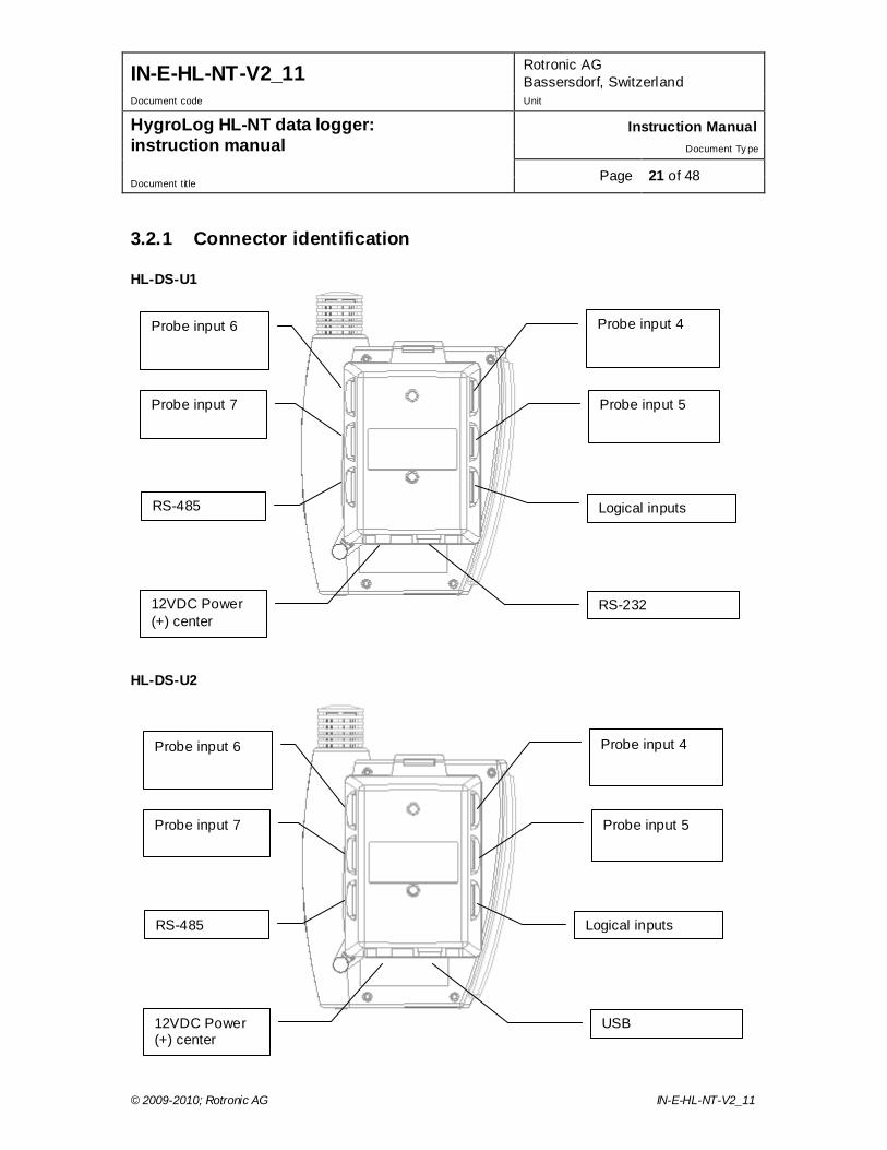
3.2.1 Connector identification HL-DS-U1 HL-DS-U2
Probe input 4
Probe input 5
Logical inputs
Probe input 6
Probe input 7
RS-485
12VDC Power (+) center
RS-232
Probe input 4
Probe input 5
Probe input 6
Probe input 7
RS-485
12VDC Power (+) center
USB
Logical inputs

IN-E-HL-NT-V2_11 Rotronic AG Bassersdorf, Switzerland
Document code Unit
HygroLog HL-NT data logger: instruction manual
Instruction Manual Document Ty pe
Page 22 of 48 Document title
© 2009-2010; Rotronic AG IN-E-HL-NT-V2_11
HL-DS-U4 / HL-DS-U4-420 HL-DS-U4-WL
Probe input 4
Probe input 5
Logical inputs
Probe input 6
RJ45
RS-485
12VDC Power (+) center
Probe input 7
Probe input 4
Logical inputs
Probe input 6
Antenna
RS-485
12VDC Power (+) center
IN-E-HL-NT-V2_11 Rotronic AG Bassersdorf, Switzerland
Document code Unit
HygroLog HL-NT data logger: instruction manual
Instruction Manual Document Ty pe
Page 23 of 48 Document title
© 2009-2010; Rotronic AG IN-E-HL-NT-V2_11
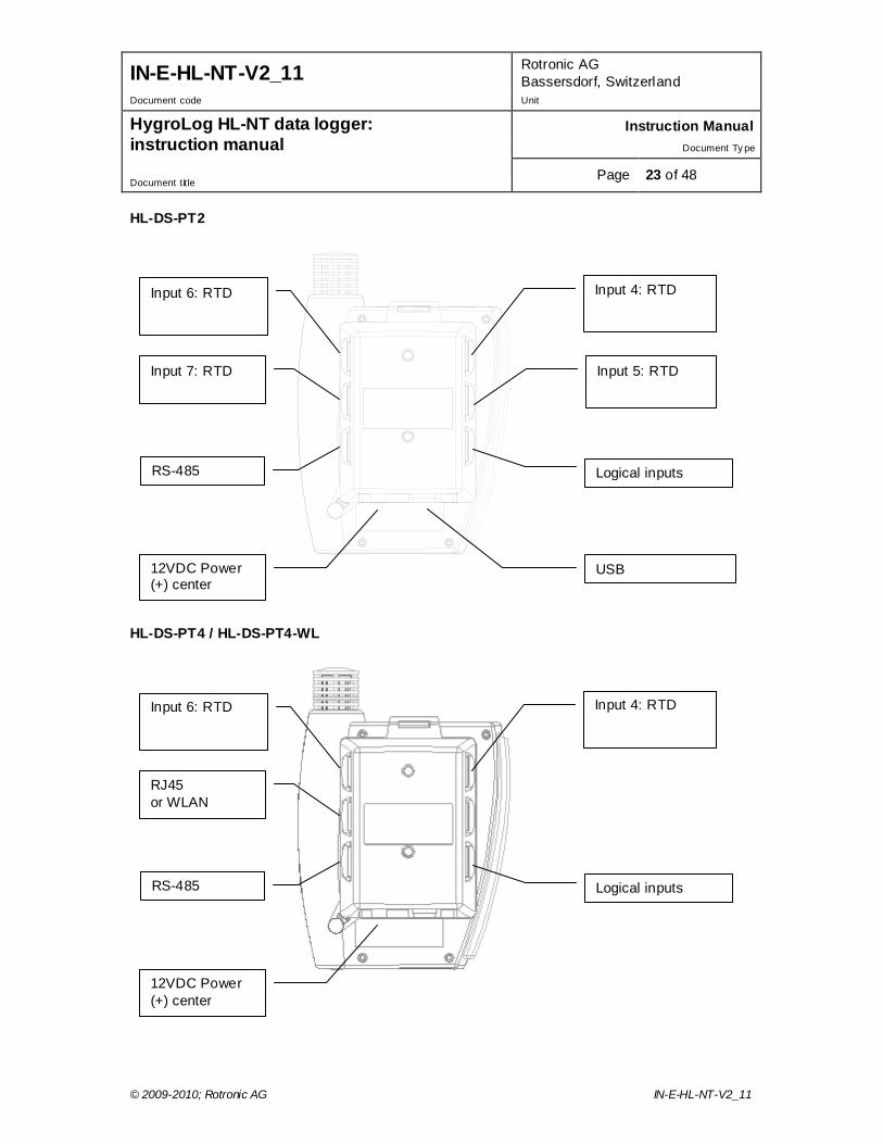
HL-DS-PT2 HL-DS-PT4 / HL-DS-PT4-WL
Input 4: RTD
Input 5: RTD
Logical inputs
Input 6: RTD
Input 7: RTD
RS-485
12VDC Power (+) center
USB
Input 4: RTD
Logical inputs
Input 6: RTD
RJ45 or WLAN
RS-485
12VDC Power (+) center
IN-E-HL-NT-V2_11 Rotronic AG Bassersdorf, Switzerland
Document code Unit
HygroLog HL-NT data logger: instruction manual
Instruction Manual Document Ty pe
Page 24 of 48 Document title
© 2009-2010; Rotronic AG IN-E-HL-NT-V2_11
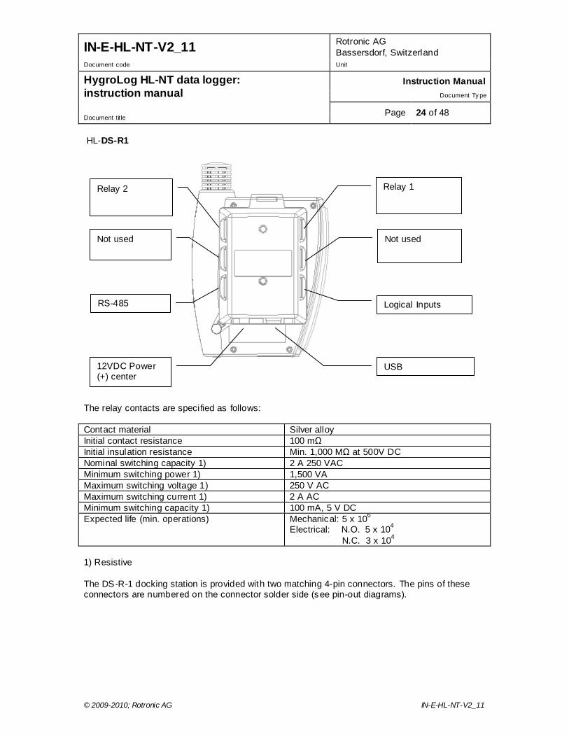
HL-DS-R1 The relay contacts are specified as follows: Contact material Silver alloy Initial contact resistance 100 mΩ Initial insulation resistance Min. 1,000 MΩ at 500V DC Nominal switching capacity 1) 2 A 250 VAC Minimum switching power 1) 1,500 VA Maximum switching voltage 1) 250 V AC Maximum switching current 1) 2 A AC Minimum switching capacity 1) 100 mA, 5 V DC Expected life (min. operations) Mechanical: 5 x 10⁶
Electrical: N.O. 5 x 10⁴ N.C. 3 x 10⁴
1) Resistive The DS-R-1 docking station is provided with two matching 4-pin connectors. The pins of these connectors are numbered on the connector solder side (see pin-out diagrams).
Relay 1
Not used
Logical Inputs
Relay 2
Not used
RS-485
12VDC Power (+) center
USB
IN-E-HL-NT-V2_11 Rotronic AG Bassersdorf, Switzerland
Document code Unit
HygroLog HL-NT data logger: instruction manual
Instruction Manual Document Ty pe
Page 25 of 48 Document title
© 2009-2010; Rotronic AG IN-E-HL-NT-V2_11
3.3 Docking station inputs Depending on the model of docking station, the signals from up to 4 additional probes can be processed by the HygroLog HL-NT.
3.3.1 HygroClip 2 probes By default inputs 4, 5, 7 and 7 of docking stations HL-DS-U1, HL-DS-U2, HL-DS-U4 and HL-DS-U4-WL are configured by the factory to accept a HygroClip 2 probe. Any model of HygroClip 2 probe can be connected these using one of the available extension cables. See document E-M-HC2-accessories.
3.3.2 1-channel analog probes with voltage output Inputs 4, 5, 7 and 7 of docking stations HL-DS-U1, HL-DS-U2, HL-U4 and HL-DS-U4-WL can also be configured to accept one of the following: o 1-channel analog probe: To be compatible with the docking station the analog probe must
meet the following requirements: supply voltage: 5 VDC, current consumption: max. 10 mA, output signal: 0 to max. 3.3 VDC. The docking station uses a 12-bit A/D converter to digitize the probe analog signal and can be configured to measure practically any parameter.
o Analog pressure probe: this is a special case of analog probe and is subject to the same compatibility requirements. When analog pressure probe is selected, any input of the HygroLog HL-NT and docking station can be configured to use the signal from the pressure probe to calculate any humidity parameter that requires barometric pressure as an input value (example: mixing ratio).
3.3.3 1-channel analog probes with current output Docking station HL-DS-U4-420 is similar to docking station HL-DS-U4 with the difference that it accepts up to four 3-wire single channel analog probes with a 4-20 mA current output signal. Each probe input uses an internal 150 Ohm resistor to convert 4…20 mA to 600…3000 mV (nominal). The HW4 software allows a 2-point adjustment of the mA to mV conversion to compensate for the tolerance on the 150 Ohm resistor (use Device Manager in HW4). The probes are powered by the docking station (supply voltage: 5 VDC, maximum current draw: 10 mA / probe).
3.3.4 Pt100 RTD 4-wire probes Docking stations HL-DS-PT2, HL-DS-PT4 and HL-DS-PT4-WL are designed for 4-wire RTD probes. These docking stations allow the measurement of temperature conditions within the range of -100 to 600°C. Accuracy depends on the class of the Pt100 RTD. Adjustment of the RTD inputs against a reference temperature is limited to a 1-point adjustment (global offset).
3.3.5 Logical inputs (on / off) Several models of docking station allow the HygroLog HL-NT to process up to 2 logical inputs. Typically this is used to monitor a relay contact, a door contact, etc.
IN-E-HL-NT-V2_11 Rotronic AG Bassersdorf, Switzerland
Document code Unit
HygroLog HL-NT data logger: instruction manual
Instruction Manual Document Ty pe
Page 26 of 48 Document title
© 2009-2010; Rotronic AG IN-E-HL-NT-V2_11
3.4 Relay contacts Docking station model HL-DS-R1 features two independent relays, each with 3 contacts: normally closed, normally open and common. When configuring the HygroLog HL-NT and docking station with the HW4 software, a number of conditions can be defined that will cause the relay to be either energized or de-energized. The relays of the HL-DS-R1 docking station can be used to provide a local indication of the following:
o Out of limit values for probe inputs 1 to 3 of the HygroLog HL-NT o Status of the two logical inputs of the DS-R-1 docking station o Memory card error o External power failure o Low battery charge
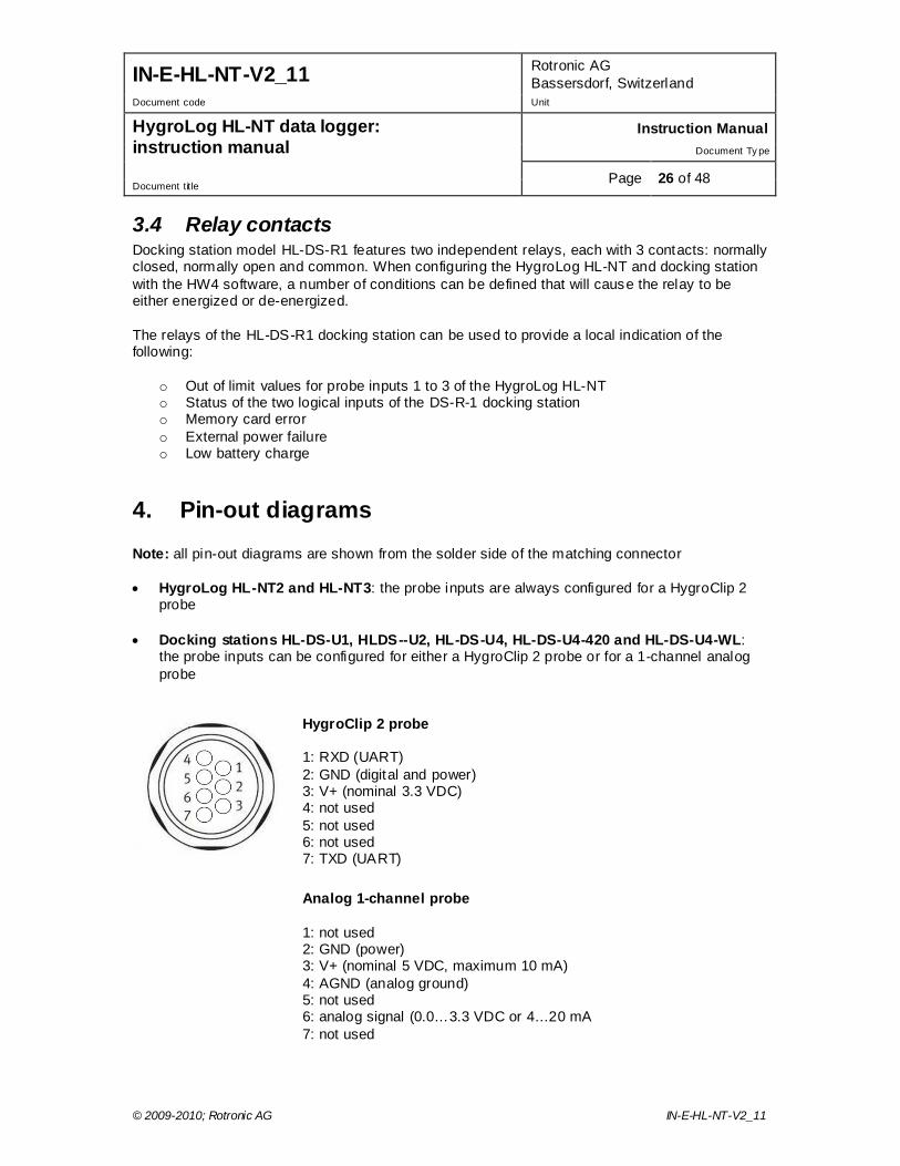
4. Pin-out diagrams Note: all pin-out diagrams are shown from the solder side of the matching connector • HygroLog HL-NT2 and HL-NT3: the probe inputs are always configured for a HygroClip 2
probe
• Docking stations HL-DS-U1, HLDS--U2, HL-DS-U4, HL-DS-U4-420 and HL-DS-U4-WL: the probe inputs can be configured for either a HygroClip 2 probe or for a 1-channel analog probe
HygroClip 2 probe 1: RXD (UART) 2: GND (digital and power) 3: V+ (nominal 3.3 VDC) 4: not used 5: not used 6: not used 7: TXD (UART)
Analog 1-channel probe 1: not used 2: GND (power) 3: V+ (nominal 5 VDC, maximum 10 mA) 4: AGND (analog ground) 5: not used 6: analog signal (0.0…3.3 VDC or 4…20 mA 7: not used
IN-E-HL-NT-V2_11 Rotronic AG Bassersdorf, Switzerland
Document code Unit
HygroLog HL-NT data logger: instruction manual
Instruction Manual Document Ty pe
Page 27 of 48 Document title
© 2009-2010; Rotronic AG IN-E-HL-NT-V2_11
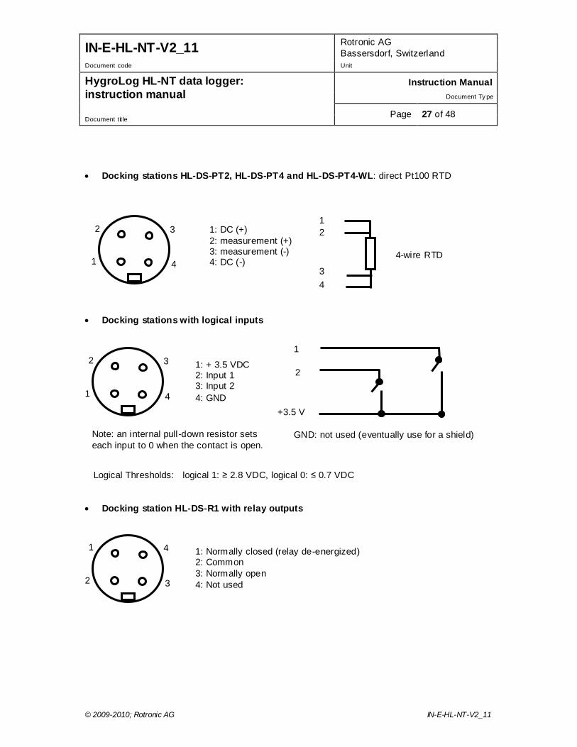
• Docking stations HL-DS-PT2, HL-DS-PT4 and HL-DS-PT4-WL: direct Pt100 RTD
• Docking stations with logical inputs
Logical Thresholds: logical 1: ≥ 2.8 VDC, logical 0: ≤ 0.7 VDC • Docking station HL-DS-R1 with relay outputs
3
4 1
2
1: Normally closed (relay de-energized) 2: Common 3: Normally open 4: Not used
4
3 2
1
1: + 3.5 VDC 2: Input 1 3: Input 2 4: GND
1
2
GND: not used (eventually use for a shield)
+3.5 V
Note: an internal pull-down resistor sets each input to 0 when the contact is open.
1: DC (+) 2: measurement (+) 3: measurement (-) 4: DC (-)
1 2
3 4
4-wire RTD 4
3 2
1
IN-E-HL-NT-V2_11 Rotronic AG Bassersdorf, Switzerland
Document code Unit
HygroLog HL-NT data logger: instruction manual
Instruction Manual Document Ty pe
Page 28 of 48 Document title
© 2009-2010; Rotronic AG IN-E-HL-NT-V2_11
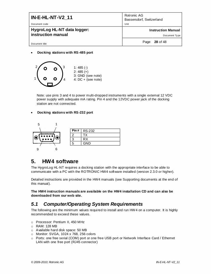
• Docking stations with RS-485 port
• Docking stations with RS-232 port
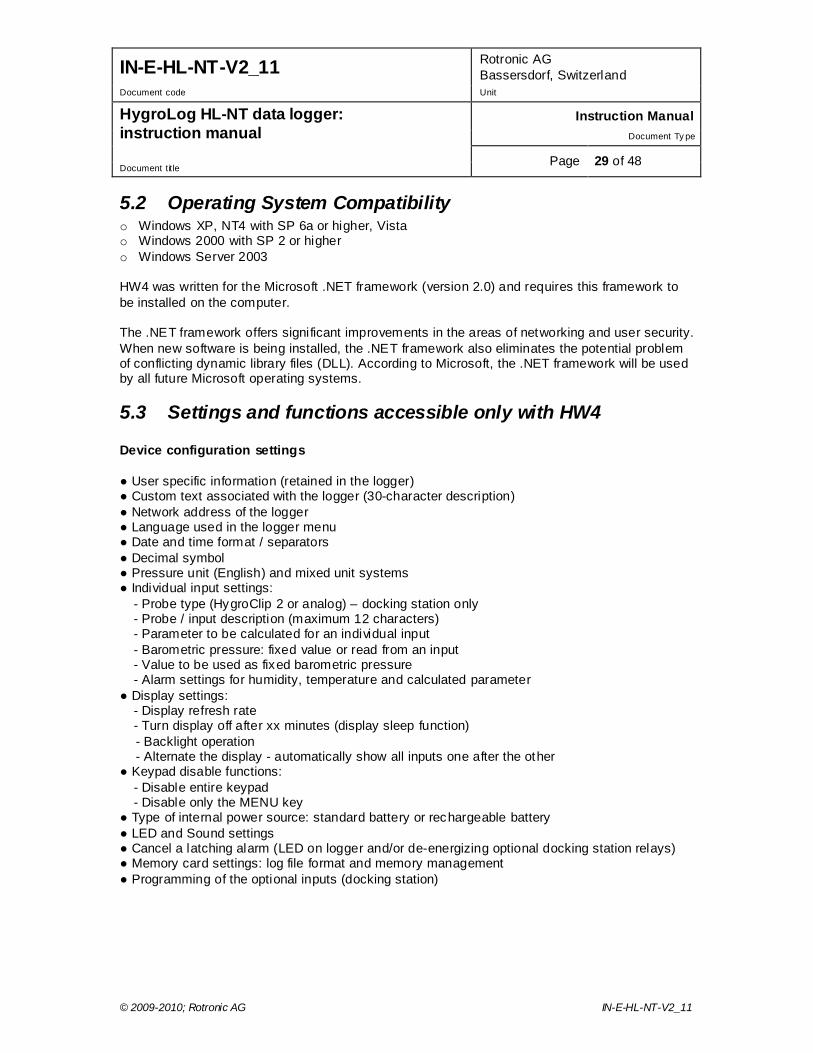
5. HW4 software The HygroLog HL-NT requires a docking station with the appropriate interface to be able to communicate with a PC with the ROTRONIC HW4 software installed (version 2.3.0 or higher). Detailed instructions are provided in the HW4 manuals (see Supporting documents at the end of this manual). The HW4 instruction manuals are available on the HW4 installation CD and can also be downloaded from our web site.
5.1 Computer/Operating System Requirements The following are the minimum values required to install and run HW4 on a computer. It is highly recommended to exceed these values. o Processor: Pentium II, 450 MHz o RAM: 128 MB o Available hard disk space: 50 MB o Monitor: SVGA, 1024 x 768, 256 colors o Ports: one free serial (COM) port or one free USB port or Network Interface Card / Ethernet
LAN with one free port (RJ45 connector)
Pin # RS-232 2 TX 3 RX 5 GND
1 5
6 9
1: 485 (-) 2: 485 (+) 3: GND (see note) 4: DC + (see note) 4
3 2
1
Note: use pins 3 and 4 to power multi-dropped instruments with a single external 12 VDC power supply with adequate mA rating. Pin 4 and the 12VDC power jack of the docking station are not connected.
IN-E-HL-NT-V2_11 Rotronic AG Bassersdorf, Switzerland
Document code Unit
HygroLog HL-NT data logger: instruction manual
Instruction Manual Document Ty pe
Page 29 of 48 Document title
© 2009-2010; Rotronic AG IN-E-HL-NT-V2_11
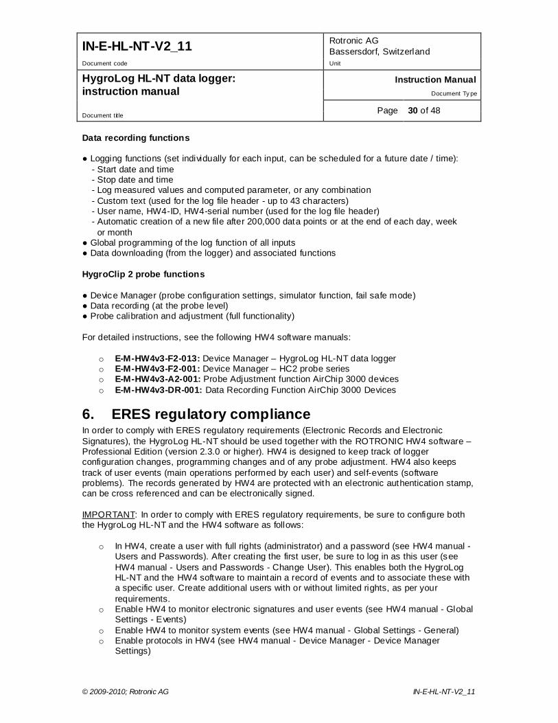
5.2 Operating System Compatibility o Windows XP, NT4 with SP 6a or higher, Vista o Windows 2000 with SP 2 or higher o Windows Server 2003 HW4 was written for the Microsoft .NET framework (version 2.0) and requires this framework to be installed on the computer. The .NET framework offers significant improvements in the areas of networking and user security. When new software is being installed, the .NET framework also eliminates the potential problem of conflicting dynamic library files (DLL). According to Microsoft, the .NET framework will be used by all future Microsoft operating systems.
5.3 Settings and functions accessible only with HW4 Device configuration settings ● User specific information (retained in the logger) ● Custom text associated with the logger (30-character description) ● Network address of the logger ● Language used in the logger menu ● Date and time format / separators ● Decimal symbol ● Pressure unit (English) and mixed unit systems ● Individual input settings:
- Probe type (HygroClip 2 or analog) – docking station only - Probe / input description (maximum 12 characters) - Parameter to be calculated for an individual input - Barometric pressure: fixed value or read from an input - Value to be used as fixed barometric pressure - Alarm settings for humidity, temperature and calculated parameter
● Display settings: - Display refresh rate - Turn display off after xx minutes (display sleep function)
- Backlight operation - Alternate the display - automatically show all inputs one after the other ● Keypad disable functions:
- Disable entire keypad - Disable only the MENU key
● Type of internal power source: standard battery or rechargeable battery ● LED and Sound settings ● Cancel a latching alarm (LED on logger and/or de-energizing optional docking station relays) ● Memory card settings: log file format and memory management ● Programming of the optional inputs (docking station)
IN-E-HL-NT-V2_11 Rotronic AG Bassersdorf, Switzerland
Document code Unit
HygroLog HL-NT data logger: instruction manual
Instruction Manual Document Ty pe
Page 30 of 48 Document title
© 2009-2010; Rotronic AG IN-E-HL-NT-V2_11
Data recording functions ● Logging functions (set individually for each input, can be scheduled for a future date / time):
- Start date and time - Stop date and time - Log measured values and computed parameter, or any combination - Custom text (used for the log file header - up to 43 characters) - User name, HW4-ID, HW4-serial number (used for the log file header) - Automatic creation of a new file after 200,000 data points or at the end of each day, week or month
● Global programming of the log function of all inputs ● Data downloading (from the logger) and associated functions HygroClip 2 probe functions ● Device Manager (probe configuration settings, simulator function, fail safe mode) ● Data recording (at the probe level) ● Probe calibration and adjustment (full functionality) For detailed instructions, see the following HW4 software manuals:
o E-M-HW4v3-F2-013: Device Manager – HygroLog HL-NT data logger o E-M-HW4v3-F2-001: Device Manager – HC2 probe series o E-M-HW4v3-A2-001: Probe Adjustment function AirChip 3000 devices o E-M-HW4v3-DR-001: Data Recording Function AirChip 3000 Devices
6. ERES regulatory compliance In order to comply with ERES regulatory requirements (Electronic Records and Electronic Signatures), the HygroLog HL-NT should be used together with the ROTRONIC HW4 software – Professional Edition (version 2.3.0 or higher). HW4 is designed to keep track of logger configuration changes, programming changes and of any probe adjustment. HW4 also keeps track of user events (main operations performed by each user) and self-events (software problems). The records generated by HW4 are protected with an electronic authentication stamp, can be cross referenced and can be electronically signed. IMPORTANT: In order to comply with ERES regulatory requirements, be sure to configure both the HygroLog HL-NT and the HW4 software as follows:
o In HW4, create a user with full rights (administrator) and a password (see HW4 manual -Users and Passwords). After creating the first user, be sure to log in as this user (see HW4 manual - Users and Passwords - Change User). This enables both the HygroLog HL-NT and the HW4 software to maintain a record of events and to associate these with a specific user. Create additional users with or without limited rights, as per your requirements.
o Enable HW4 to monitor electronic signatures and user events (see HW4 manual - Global Settings - Events)
o Enable HW4 to monitor system events (see HW4 manual - Global Settings - General) o Enable protocols in HW4 (see HW4 manual - Device Manager - Device Manager
Settings)
IN-E-HL-NT-V2_11 Rotronic AG Bassersdorf, Switzerland
Document code Unit
HygroLog HL-NT data logger: instruction manual
Instruction Manual Document Ty pe
Page 31 of 48 Document title
© 2009-2010; Rotronic AG IN-E-HL-NT-V2_11
If the HygroLog HL-NT has a display and keypad, disable the MENU key (see HW4 manual - Device Manager - HygroLog HL-NT - Keypad).
7. Getting started Insert a 9V alkaline battery in the HygroLog HL-NT as explained under Hardware Description - Power. To conserve battery power, models with a display are shipped with the Display Sleep function enabled. With this function enabled and when logging is not active, the logger just keeps track of the date and time and uses very little battery power. Press any key on the keypad to temporarily suspend the Display Sleep function. The HW4 software is required to either disable the Display Sleep function or to reconfigure this function. See Display Sleep function under Software Functions
8. Stand-alone operation
8.1 Operating modes The HygroLog HL-NT has two main operating modes: measure and record. ● Measure mode: the HygroLog HL-NT defaults to this mode when it is not recording any data.
What happens in this mode depends on whether or not the HygroLog HL-NT is communicating with a PC. When there is no communication with a PC, the model without display is in a low power consumption mode and just keeps track of the date and time. The model with display behaves differently, depending on whether or not the Display Sleep function is enabled (see Software Functions). If the function is disabled (display always on), measurements take place at intervals of time corresponding to the display refresh interval that was specified with HW4 when configuring the data logger. When the display goes blank because the Display Sleep function is enabled, the model with display behaves in the same manner as the model without display.
● Record mode: the model without display measures data according to the log interval that was specified for each individual input. The shortest log interval is 5 seconds. The log interval and the measurement interval are the same. In the case of the model with display, the measurement interval is the shortest of the log interval and display refresh interval. If the Display Sleep function is active, the measurement interval is by default the same as the log interval.
8.2 Display and keypad Depending on the model, the HygroLog HL-NT is equipped with a display and a keypad. Display The HygroLog HL-NT uses a monochrome graphic LC display with backlight. The backlight works only when the HygroLog HL-NT is powered via a docking station. The normal function of the display is to show the most recent measured values, one at a time. The display is also used to navigate the Function Menu of the HygroLog HL-NT.
IN-E-HL-NT-V2_11 Rotronic AG Bassersdorf, Switzerland
Document code Unit
HygroLog HL-NT data logger: instruction manual
Instruction Manual Document Ty pe
Page 32 of 48 Document title
© 2009-2010; Rotronic AG IN-E-HL-NT-V2_11
IMPORTANT: Using the HW4 software, the display can be set to automatically go blank after a specific time interval when there is no keypad activity and when there is no communication over the UART interface. This serves the purpose of conserving battery power. The display comes up again when any key is pressed or when a communication is initiated. See Software Functions, Display Sleep function. HW4 is also required to configure the operation of the display backlight: always off, always on, on key press (default setting). Keypad The keypad of the HygroLog HL-NT is comprised of the following keys: ● MENU: press this key to open the function menu, to go back one menu level or to exit the
menu. ● ENTER: this key has two functions:
If the function menu is not open, press this key to switch the display between showing the measured values, date, time and probe number and showing the measured values and calculated parameter (if HW4 was used to associate a calculated parameter with the probe). If the function menu is open, press this key to select a menu item and/or to confirm a value or setting.
● UP: the up-arrow key has two functions:
If the function menu is not open, the up-arrow key is used to switch the display between the different probe inputs. If the function menu is open, the up-arrow key is used to navigate the function menu and/or to change the setting or value of a menu function.
● DOWN: the down-arrow key has a similar functionality as the up-arrow key: IMPORTANT: the HW4 software can be used to disable either the MENU key or the entire keypad. If the keypad does not work, you should check the configuration of the HygroLog HL-NT with HW4. Disabling the MENU key prevents unauthorized changes to the configuration of the HygroLog HL-NT and also prevents any probe adjustment. Compliance with FDA / GAMP requires the MENU key to be disabled.

IN-E-HL-NT-V2_11 Rotronic AG Bassersdorf, Switzerland
Document code Unit
HygroLog HL-NT data logger: instruction manual
Instruction Manual Document Ty pe
Page 33 of 48 Document title
© 2009-2010; Rotronic AG IN-E-HL-NT-V2_11
8.3 Display modes The display shows the measurement data for one input at a time. Values shown on the display are updated according a refresh interval that can be set with the HW4 software. Use the UP or the DOWN arrow key to switch between inputs. Two different modes are available to display the measurement data. Use the ENTER key to toggle between the two modes: ● Display Mode 1:
Measured value 1 (usually relative humidity Measured value 2 (usually temperature) Date and time Probe / input description (as entered with HW4 when configuring the HygroLog HL-NT) Note: the bottom line of the display remains empty if no description was entered for the probe input.
● Display Mode 2:
Measured value 1 (usually relative humidity) Measured value 2 (usually temperature) Calculated parameter (as selected with HW4 when configuring the HygroLog HL-NT) Note: in this mode, the last line of the display shows the symbols --.- when no calculated parameter was selected with HW4.
In both modes, a trend indicator appears to the left of each measured value when the trend function is enabled. See Software Functions, Trend Indicators.
8.4 Settings and functions accessible from the Keypad Note: access to the following functions can be prevented by disabling the MENU key when configuring the HygroLog HL-NT with the HW4 software. The following settings can be entered / programmed from either the Keypad or with the HW4 software: ● Display mode: measured and calculated values or measured values, date, time and probe /
input description ● Unit System (metric or English) - configuring some English units such as pressure requires
HW4 ● Trend indicators on / off ● Symbol used for humidity ● Contrast of the LC display ● Decimal resolution of the display ● Date ● Time ● Enable / disable optional Bluetooth transceiver ● Cancel alarm (works only when the latching mode is enabled)
IN-E-HL-NT-V2_11 Rotronic AG Bassersdorf, Switzerland
Document code Unit
HygroLog HL-NT data logger: instruction manual
Instruction Manual Document Ty pe
Page 34 of 48 Document title
© 2009-2010; Rotronic AG IN-E-HL-NT-V2_11
● Logging functions (set individually for each input, cannot be scheduled for a future date / time): - Start logging - Stop logging - Log Interval
● View recorded data (in table form only) ● Probe adjustment function, limited to a 1-point adjustment of humidity and temperature one
probe at a time (HygroClip 2 probes only)
8.5 Internal function menu (models with display and keypad)
8.5.1 Log data This menu item is used to immediately start or stop recording data from each individual input. Log operations that are set in the future and / or settings that apply globally to all probe inputs cannot be programmed from here. When data logging is not active, selecting this menu item displays the following: ● Probe: probe name (custom name specified by user)
To change the probe, use the up or down arrow key to highlight probe and press ENTER. Use the arrow keys to change the probe and press ENTER to confirm the selection.
● Interval: log interval in HH:mm:ss ● START LOGGING: record data immediately ● EXIT: exit the log data function When data logging is either in progress or has been scheduled at a future time, the third menu item (START LOGGING) changes to: ● STOP LOGGING: stop recording data immediately
8.5.2 View data This menu item is used to view on the LC display data from the most recent log file for the selected probe (older log files cannot be opened with this menu item). ● Probe: probe name (custom name specified by user)
To change the probe, use the up or down arrow key to highlight probe and press ENTER. Use the arrow keys to change the probe and press ENTER to confirm the selection.
● [OPEN]: select and press ENTER to review the data ● [EXIT]: select and press ENTER to exit this menu item If there is no log file in the flash memory card for the selected probe, the message “Log file not found” appears. When there is at least one log file for the selected probe, data from the most recent file is presented in table form, showing 7 lines of data at a time. Each line corresponds to the log interval that was in effect when the data was recorded. The date and time corresponding to line 4 (this line is always highlighted) are displayed at the bottom of the display. The first 7 data points of the log file are presented first. Press the UP arrow key to view the next 7 data points. Press the DOWN arrow key to view again the previous data points. Both the date and time change at the bottom of the display as the arrow keys are pressed until the beginning or end of the log file has been reached.
IN-E-HL-NT-V2_11 Rotronic AG Bassersdorf, Switzerland
Document code Unit
HygroLog HL-NT data logger: instruction manual
Instruction Manual Document Ty pe
Page 35 of 48 Document title
© 2009-2010; Rotronic AG IN-E-HL-NT-V2_11
For a faster data review, press the ENTER key. The scrolling step is displayed at the top of the display and changes each time that the ENTER key is pressed. For example, with the scrolling step set to 7 and a log interval of 30 seconds, time moves in increments of 3 minutes and 30 seconds (7 x 30 seconds) each time that one of the arrow keys is being pressed. Press the MENU key to exit the data table.
8.5.3 Adjust This menu item can be used to do a 1-point adjustment of any ROTRONIC HygroClip 2 probe that is connected to the HygroLog HL-NT or docking station. The adjust function cannot be used with other types of probe. IMPORTANT: see the instructions provided under “HygroClip probe adjustment procedures” before using this function. ● Probe: probe name (custom name specified by user)
To change the probe, use the up or down arrow key to highlight probe and press ENTER. Use the arrow keys to change the probe and press ENTER to confirm the selection.
● Adjust: parameter to be adjusted (humidity, humidity RHS or temperature) ● Mode: adjustment type (single-point only) ● RefValue: reference value against which the probe will be adjusted ● ADJUST: adjust the probe ● EXIT: exit the adjust function Note: next to the word “current”, the bottom of the display shows the value of the parameter to be adjusted at the time the parameter to be adjusted was selected. This value is not updated while the Adjust menu item is active (exit Adjust to update the value).
8.5.4 Settings This menu item allows both to review and to modify some of the settings of the HygroLog HL-NT and to cancel (reset) a permanent alarm condition. ● Trend: turn trend indicators on or off. ● Units: use Metric or English unit system ● H.Symbol: select the symbol to be used for relative humidity RH, Aw, HR, rh, rF ● Contrast: contrast setting, 0% is the minimum and 100% is the maximum ● Decimals: decimal resolution of the display 1 or 2. ● Date ● Time ● Cancel Alarm (used to cancel an alarm when the latching mode is enabled) ● Exit To change a setting: - Use the UP or DOWN key to highlight the setting to be changed. The entire line corresponding to the setting is highlighted. - Press on the ENTER key to select the setting. Only the value of the setting is highlighted. - Use the UP or DOWN key to review the available setting values - When the desired value is displayed, press on the ENTER key - The entire line corresponding to the setting is highlighted again.

IN-E-HL-NT-V2_11 Rotronic AG Bassersdorf, Switzerland
Document code Unit
HygroLog HL-NT data logger: instruction manual
Instruction Manual Document Ty pe
Page 36 of 48 Document title
© 2009-2010; Rotronic AG IN-E-HL-NT-V2_11
To cancel an alarm when the latching mode is enabled: - Use the UP or DOWN key to highlight the line that says [Cancel Alarm]. - Press on the ENTER key.
8.5.5 Instrument This menu item provides information on the HygroLog HL-NT. No changes can be made from within this menu item. ● Release: firmware release ● S/N: serial number ● Address (network address of the logger) ● Baud rate: serial transmission rate ● Battery: % remaining battery capacity (automatically reset to 100% after replacing the battery) ● Ext. Power: No (not connected), Yes (connected) ● Name: custom name specified by the user for the logger (max. 30 characters) Press the ENTER key to exit this menu item
8.5.6 Inputs This menu item provides information on the inputs of the HygroLog HL-NT and optional docking station. No changes can be made from within this menu item. Information is shown one input at a time. The input number appears on the top of the screen and can be changed with the up-arrow or with the down arrow key. ● Status: Connected / Not Detected - shows if a probe is connected or not ● Name: custom name specified by the user for the input (max. 12 characters) ● Release: firmware release of the probe (HygroClip probes only) ● S/N: serial number of the probe (HygroClip probes only) ● Logging: status of the logging function for the input being displayed - scheduled: data from the input is scheduled to be logged at a future time
- active: data from the input is being logged - inactive: no input data is being logged or scheduled to be logged
8.5.7 Docking station This menu item provides information on any docking station with internal electronics that is attached to the HygroLog HL-NT. No changes can be made from within this menu item. ● Status: Connected / Not Detected ● Release: firmware release of the docking station ● S/N: serial number of the docking station
IN-E-HL-NT-V2_11 Rotronic AG Bassersdorf, Switzerland
Document code Unit
HygroLog HL-NT data logger: instruction manual
Instruction Manual Document Ty pe
Page 37 of 48 Document title
© 2009-2010; Rotronic AG IN-E-HL-NT-V2_11
9. Operation on a network
9.1 Baud rate and communications protocol compatibility requirements
Depending on the model, devices from ROTRONIC use one of the following Baud rates as the factory default: • 57600 bps: HygroLog HL-NT data logger and docking stations
• 19200 bps: HygroPalm and HygroLab indicators, HygroFlex and M33 transmitters,
HygroClip Alarm programmable alarm card, HygroClip DI interface, HygroStat MB Thermo-Hygrostat
IMPORTANT: • All devices connected to the same RS-485 multi-drop network (master and slaves) must
use the same Baud rate and the same communications protocol. The communications protocol used by the HygroLog HL-NT is compatible with previous versions of the HygroLog NT and with legacy products such as the HygroFlex 2 or 3. The HygroLog HL-NT cannot be used in the same RS-485 multi-drop network as a HF4 or HF5 transmitter and similar products that rely on the RO-ASCII communications protocol..
• In the case of a docking station with an internal Ethernet (TCP/IP) module, the Baud rate of the Ethernet module must be the same as the Baud rate of the HygroLog HL-NT used with the docking station.
Devices and internal Ethernet modules with mismatched Baud rate will not communicate together. • The Baud rate configuration of a ROTRONIC device can be changed with the Device
Manager function (Digital Interface tab) available from within the HW4 software. • The Baud rate of a Digi internal Ethernet module can be changed only from the module
web interface. See separate document IN-E-TCPIP-Conf_11 (available in PDF format).
9.2 Ethernet local area network ROTRONIC devices with an Ethernet (TCP/IP) interface presently use an internal module manufactured by Digi International (Digi Connect ME for a wired connection, Digi Connect WI-ME for a wireless connection). Both types of module feature a web interface that is used to configure the module. IMPORTANT: The TCP/IP settings of any docking station with Ethernet interface should be configured to be compatible with the local area network. Detailed instructions are provided separately in document IN-E-TCPIP-Conf_11 (available in PDF format).
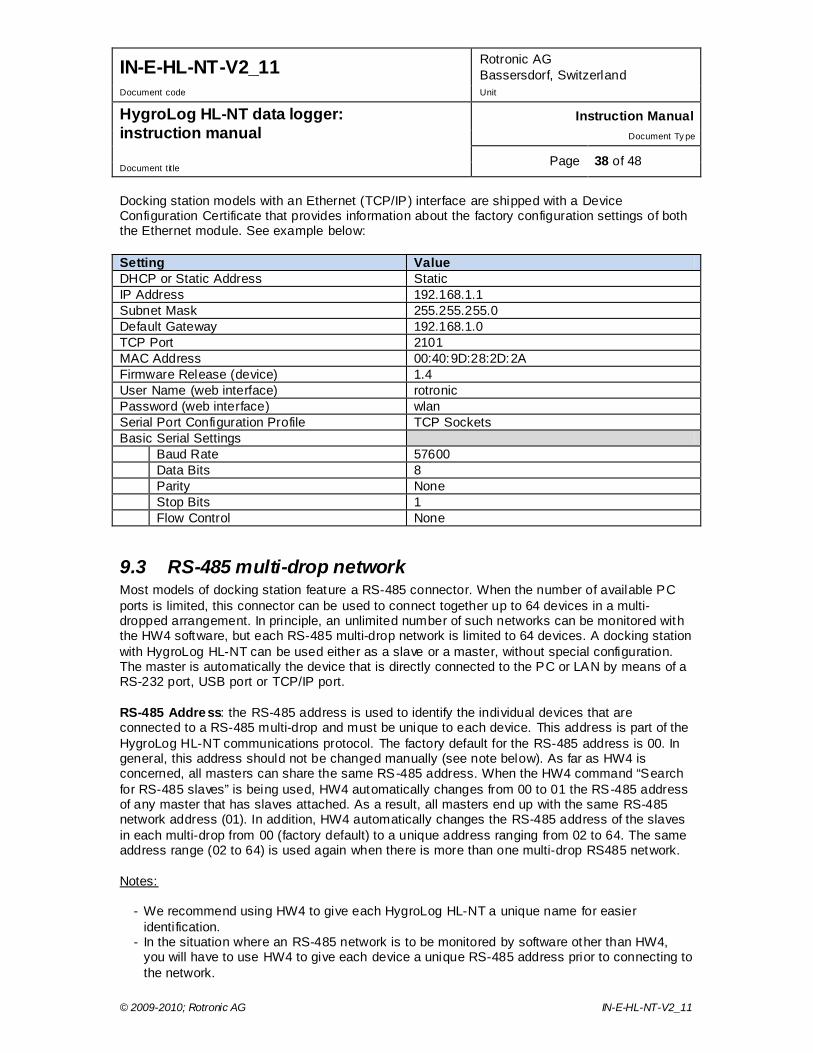
IN-E-HL-NT-V2_11 Rotronic AG Bassersdorf, Switzerland
Document code Unit
HygroLog HL-NT data logger: instruction manual
Instruction Manual Document Ty pe
Page 38 of 48 Document title
© 2009-2010; Rotronic AG IN-E-HL-NT-V2_11
Docking station models with an Ethernet (TCP/IP) interface are shipped with a Device Configuration Certificate that provides information about the factory configuration settings of both the Ethernet module. See example below: Setting Value DHCP or Static Address Static IP Address 192.168.1.1 Subnet Mask 255.255.255.0 Default Gateway 192.168.1.0 TCP Port 2101 MAC Address 00:40:9D:28:2D:2A Firmware Release (device) 1.4 User Name (web interface) rotronic Password (web interface) wlan Serial Port Configuration Profile TCP Sockets Basic Serial Settings Baud Rate 57600 Data Bits 8 Parity None Stop Bits 1 Flow Control None
9.3 RS-485 multi-drop network Most models of docking station feature a RS-485 connector. When the number of available PC ports is limited, this connector can be used to connect together up to 64 devices in a multi-dropped arrangement. In principle, an unlimited number of such networks can be monitored with the HW4 software, but each RS-485 multi-drop network is limited to 64 devices. A docking station with HygroLog HL-NT can be used either as a slave or a master, without special configuration. The master is automatically the device that is directly connected to the PC or LAN by means of a RS-232 port, USB port or TCP/IP port. RS-485 Address: the RS-485 address is used to identify the individual devices that are connected to a RS-485 multi-drop and must be unique to each device. This address is part of the HygroLog HL-NT communications protocol. The factory default for the RS-485 address is 00. In general, this address should not be changed manually (see note below). As far as HW4 is concerned, all masters can share the same RS-485 address. When the HW4 command “Search for RS-485 slaves” is being used, HW4 automatically changes from 00 to 01 the RS-485 address of any master that has slaves attached. As a result, all masters end up with the same RS-485 network address (01). In addition, HW4 automatically changes the RS-485 address of the slaves in each multi-drop from 00 (factory default) to a unique address ranging from 02 to 64. The same address range (02 to 64) is used again when there is more than one multi-drop RS485 network. Notes:
- We recommend using HW4 to give each HygroLog HL-NT a unique name for easier identification.
- In the situation where an RS-485 network is to be monitored by software other than HW4, you will have to use HW4 to give each device a unique RS-485 address prior to connecting to the network.

IN-E-HL-NT-V2_11 Rotronic AG Bassersdorf, Switzerland
Document code Unit
HygroLog HL-NT data logger: instruction manual
Instruction Manual Document Ty pe
Page 39 of 48 Document title
© 2009-2010; Rotronic AG IN-E-HL-NT-V2_11
Example: HygroLog HL-NT and docking station with USB port The number of HygroLog HL-NT and docking station with USB port that can be directly connected to a PC depends on the number of USB ports available on the PC. IMPORTANT:
- If you change an instrument from master to slave, be sure to change the RS address of the instrument to 00 before establishing the RS-485 connection. Not doing so may prevent HW4 from detecting the instrument. After detecting the instrument, HW4 will automatically change the RS address to 02 or higher. Please note that HW4 may eventually change the address of any master with address 00.
- All devices connected to the same RS-485 multi-drop should use the same Baud rate and the
same communications protocol.
- Docking stations with Ethernet (TCP/IP) interface: please note that the Baud rate of the HygroLog HL-NT and the Baud rate of the docking station internal Ethernet module should be set to the same value
The RS485 wiring can be done with a twisted pair (2-wire, telephone type) and wall mounted RJ45 receptacles (see Electrical installation guidelines in this manual). Be sure to observe the polarity for each connection. Using 4-wire cable, offers the option of powering all devices in the multi-drop from a single DC voltage source.
9.4 General wiring guidelines Power supply wiring Heavy machinery and instrumentation should not share the same power supply wiring. If this cannot be avoided, noise filters and surge protectors should be used. Most UPS devices have those features already integrated. General guidelines for signal cables The following guidelines are derived from European Standard EN 50170 for the transmission of signals by copper wires. When planning an installation, the rules provided by EN 50170 should be
RS485: 2 wires
PC (HW4)
USB port Master Address 1 Address 2 Address 64
NT USB
RS485 RS485 RS485
Multi-drop: up to 1000m (3300 ft)
Slave Slave

IN-E-HL-NT-V2_11 Rotronic AG Bassersdorf, Switzerland
Document code Unit
HygroLog HL-NT data logger: instruction manual
Instruction Manual Document Ty pe
Page 40 of 48 Document title
© 2009-2010; Rotronic AG IN-E-HL-NT-V2_11
followed under consideration of local circumstances to determine the position of machines and equipment. All ROTRONIC products are tested for Electromagnetic Compatibility according to EMC Directive 2004/106/EG and following European standards:
o EN 61000-6-1: 2001, EN 61000-6-2: 2005 o EN 61000-6-3: 2005, EN 61000-6-4: 2001 + A11
Whenever the level of electromagnetic interference is expected to be high, both the instruments and signal cables should be placed as far away as possible from the source of interference. In general, signal cables should be installed in bundles or channels / conduits, separate from other cables as indicated in the table below:
• Bus signals such as RS485 • Data signals for PCs, printers etc. • shielded analog inputs • unshielded direct current (<= 60V) • shielded process signals (<= 25 V) • unshielded alternate current (<= 25V) • coaxial cables for CRT monitors
in common bundles or channels / conduits
• direct current from 60 V to 400 V (unshielded)
• alternate current from 25V to 400 V (unshielded)
in separated bundles or channels /
conduits, without minimum distance
• direct and alternate current > 400 V (unshielded)
• Telephone lines • lines leading into EX-rated areas
in separated bundles or channels /
conduits, without minimum distance
Lightning protection Cabling in areas with a risk of lightning requires a lightning protection. For cabling underground in between buildings, we recommend the use of special fiber optic cables. If this is not possible, use copper cables that are suitable for underground installation.
9.5 Guidelines for RS-485 wiring See document E-DV04-RS485.01: RS485 Network Installation and Start -up Guidelines

IN-E-HL-NT-V2_11 Rotronic AG Bassersdorf, Switzerland
Document code Unit
HygroLog HL-NT data logger: instruction manual
Instruction Manual Document Ty pe
Page 41 of 48 Document title
© 2009-2010; Rotronic AG IN-E-HL-NT-V2_11
10. HygroClip probe adjustment procedures
10.1 Single Point adjustment Definition The Single-Point function permits to do a 1-point adjustment (temperature or humidity) of a ROTRONIC HygroClip 2igital probe against a known reference environment. This function is limited to a simple offset adjustment that is applied across the entire measuring range. Warning: a 1-point adjustment is no substitute for a full calibration (2 or more points). Doing a 1-point adjustment can improve accuracy over a narrow range of conditions but may also be detrimental to accuracy at other conditions. Procedure IMPORTANT: always adjust temperature first (i f temperature needs to be adjusted) Wait for the probe to be at equilibrium before using the ADJUST function. Use the UP or DOWN key to highlight any menu item. Press on the ENTER key to select the menu item. Only the value of the item is highlighted. Use the UP or DOWN key to review the available choices or to change a numerical value. When the desired selection or value is displayed, press on the ENTER key. The entire line corresponding to the menu item is highlighted again. Make the appropriate selections from the ADJUST menu: ● Probe: name of the probe to be adjusted (custom name specified by user)
To change the probe, use the up or down arrow key to highlight probe and press ENTER. Use the arrow keys to change the probe and press ENTER to confirm the selection.
● Adjust: select here the parameter to be adjusted
Humidity: humidity adjustment against a stable environment of known value. Humi RHS: humidity adjustment against a ROTRONIC certified standard 1) Temperature: temperature adjustment against a stable environment of known value. 1) For adjusting humidity, ROTRONIC offers convenient, certified humidity standards to generate known humidity values (see separate probe calibration manual).
● Mode: select Single Point ● RefValue: Use the UP or DOWN key to change the numerical value of the reference to be used
for the adjustment. For a faster change of the numerical value, keep the key pressed down. If using a ROTRONIC humidity standard (Humi RHS), use the mean value (at 23°C) written on the certificate supplied with the standard. Note: in the RHS mode, the software automatically compensates for the effect of temperature on the humidity standard. No additional correction is required.
● ADJUST: highlight this menu item and press on ENTER to do the adjustment
IN-E-HL-NT-V2_11 Rotronic AG Bassersdorf, Switzerland
Document code Unit
HygroLog HL-NT data logger: instruction manual
Instruction Manual Document Ty pe
Page 42 of 48 Document title
© 2009-2010; Rotronic AG IN-E-HL-NT-V2_11
● EXIT: highlight this menu item and press on ENTER to exit the ADJUST function The bottom of the display shows the word “Current” and the value read by the probe at the time the ENTER key was pressed Note: you can exit the ADJUST function at any time (without adjusting the probe) by pressing the MENU key.
10.2 Multi-Point adjustment This is an HW4 software function and is available only when the HygroLog HL-NT is connected to a PC running the HW4 software (version 2.3.0 or higher). See the following documents: o E-M-HW4v3-F2-013: HW4 software version 2: Device Manager – HygroLog HL-NT data
logger
o E-M-HW4v3-A2-001: HW4 software version 2: Probe Adjustment function AirChip 3000 devices
11. Warnings and useful tips • Battery Power: when no external AC adapter is connected, use the HW4 software to set the
display to automatically go blank after a specific time interval when there is no keypad activity or communication over the UART interface. Set both the display refresh rate and the log interval to the highest values compatible with your application. Avoid using a docking station with internal electronics without using an AC adapter. Do not connect several probes to the HygroLog HL-NT without using an AC adapter.
• Do not attempt to charge a regular battery: when using a regular battery, configure the logger with HW4 so as to disable the internal battery charge function of the logger. Trying to recharge a regular battery is potentially dangerous.
• Date and Time Format: prior to using your logger for the first time, be sure to verify the following configuration settings: date format (including separator), time format (including separator) and decimal separator. In order to be able to read log files on a PC, these settings must be identical to the settings of the PC operating system. If necessary, use HW4 to re-configure your logger.
• Internal Probe (Input 1): for a faster response, use the probe in the extended position.
• Compliance with ERES regulatory requirements: Use the HW4 software to disable either the MENU key or the entire keypad. Disabling the MENU key prevents unauthorized changes to the configuration of the HygroLog HL-NT and also prevents any probe adjustment.
IN-E-HL-NT-V2_11 Rotronic AG Bassersdorf, Switzerland
Document code Unit
HygroLog HL-NT data logger: instruction manual
Instruction Manual Document Ty pe
Page 43 of 48 Document title
© 2009-2010; Rotronic AG IN-E-HL-NT-V2_11
12. Communications protocol The communications protocol used by the HygroLog HL-NT is the same as for previous versions of the HygroLog NT. For customers who for any reason cannot use the HW4 software, a description of the HygroLog HL-NT communications protocol is available in document Com_NT.pdf available directly from ROTRONIC or from our web site.
13. Firmware updates Firmware updates require a return to the factory and cannot be done with the HW4.
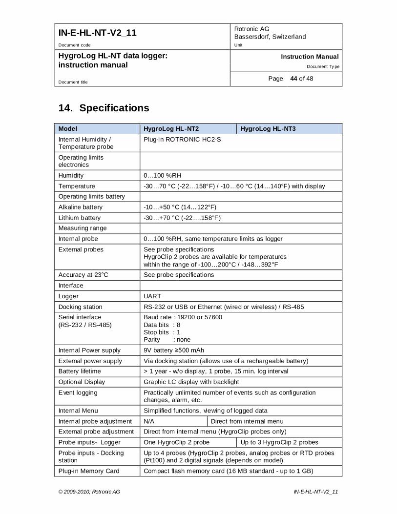
IN-E-HL-NT-V2_11 Rotronic AG Bassersdorf, Switzerland
Document code Unit
HygroLog HL-NT data logger: instruction manual
Instruction Manual Document Ty pe
Page 44 of 48 Document title
© 2009-2010; Rotronic AG IN-E-HL-NT-V2_11
14. Specifications Model HygroLog HL-NT2 HygroLog HL-NT3 Internal Humidity / Temperature probe
Plug-in ROTRONIC HC2-S
Operating limits electronics
Humidity 0…100 %RH
Temperature -30…70 °C (-22…158°F) / -10…60 °C (14…140°F) with display Operating limits battery
Alkaline battery -10…+50 °C (14…122°F)
Lithium battery -30…+70 °C (-22….158°F) Measuring range
Internal probe 0…100 %RH, same temperature limits as logger
External probes See probe specifications HygroClip 2 probes are available for temperatures within the range of -100…200°C / -148…392°F
Accuracy at 23°C See probe specifications
Interface
Logger UART
Docking station RS-232 or USB or Ethernet (wired or wireless) / RS-485 Serial interface (RS-232 / RS-485)
Baud rate : 19200 or 57600 Data bits : 8 Stop bits : 1 Parity : none
Internal Power supply 9V battery ≥500 mAh
External power supply Via docking station (allows use of a rechargeable battery) Battery lifetime > 1 year - w/o display, 1 probe, 15 min. log interval
Optional Display Graphic LC display with backlight
Event logging Practically unlimited number of events such as configuration changes, alarm, etc.
Internal Menu Simplified functions, viewing of logged data
Internal probe adjustment N/A Direct from internal menu External probe adjustment Direct from internal menu (HygroClip probes only)
Probe inputs- Logger One HygroClip 2 probe Up to 3 HygroClip 2 probes
Probe inputs - Docking station
Up to 4 probes (HygroClip 2 probes, analog probes or RTD probes (Pt100) and 2 digital signals (depends on model)
Plug-in Memory Card Compact flash memory card (16 MB standard - up to 1 GB)
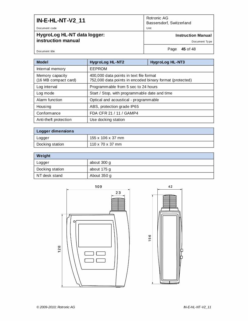
IN-E-HL-NT-V2_11 Rotronic AG Bassersdorf, Switzerland
Document code Unit
HygroLog HL-NT data logger: instruction manual
Instruction Manual Document Ty pe
Page 45 of 48 Document title
© 2009-2010; Rotronic AG IN-E-HL-NT-V2_11
Model HygroLog HL-NT2 HygroLog HL-NT3 Internal memory EEPROM
Memory capacity (16 MB compact card)
400,000 data points in text file format 752,000 data points in encoded binary format (protected)
Log interval Programmable from 5 sec to 24 hours Log mode Start / Stop, with programmable date and time
Alarm function Optical and acoustical - programmable
Housing ABS, protection grade IP65
Conformance FDA CFR 21 / 11 / GAMP4 Anti-theft protection Use docking station Logger dimensions Logger 155 x 106 x 37 mm Docking station 110 x 70 x 37 mm Weight Logger about 300 g
Docking station about 175 g NT desk stand About 350 g
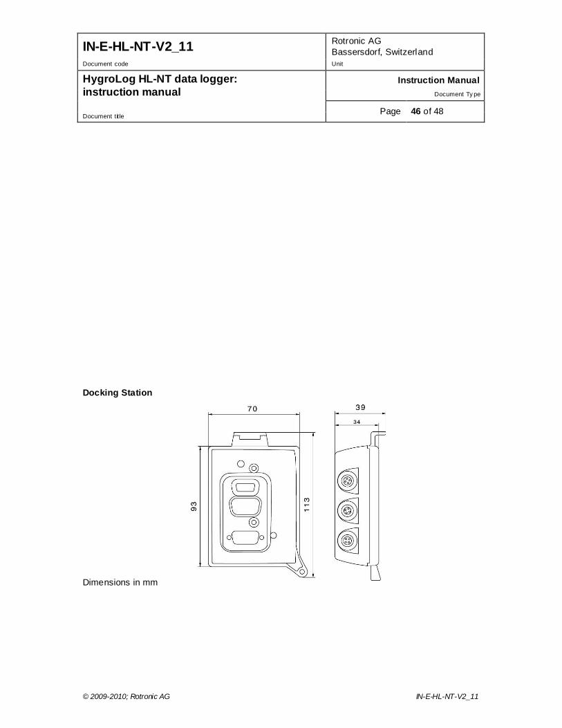
IN-E-HL-NT-V2_11 Rotronic AG Bassersdorf, Switzerland
Document code Unit
HygroLog HL-NT data logger: instruction manual
Instruction Manual Document Ty pe
Page 46 of 48 Document title
© 2009-2010; Rotronic AG IN-E-HL-NT-V2_11
Docking Station Dimensions in mm
IN-E-HL-NT-V2_11 Rotronic AG Bassersdorf, Switzerland
Document code Unit
HygroLog HL-NT data logger: instruction manual
Instruction Manual Document Ty pe
Page 47 of 48 Document title
© 2009-2010; Rotronic AG IN-E-HL-NT-V2_11
15. Accessories Order Code Description
NT-Desk Desktop stand for HygroLog HL-NT with docking station
AC1211 AC adapter 12VDC / 200mA, includes adapter for US receptacles
11.01.6218 Data cable RS232 - docking station to PC (length 1.8 m / 5.9 ft)
2/11/8818 Data cable USB type A-B - docking station to PC (length 1.8 m / 5.9 ft)
AC1614-02 RS-485 cable with 3-pin connector and tinned ends. Suitable for connecting to a terminal box. Length 2 meter / 6.5 ft.
AC-NT16MB Compact flash memory card 16 MB
AC-NT32MB Compact flash memory card 32 MB
AC-NT64MB Compact flash memory card 64 MB
15.08.6212 Flash card reader, incl. USB cable and driver For accessories and parts such as the HW4 software, probe extension cables, calibration accessories and spare dust filters, please see document E-M-HC2-accessories
16. Supporting documents Document File Name Contents
E-M-HC2 Probes-V1 HygroClip 2 (HC2) Humidity Temperature Probes, User Guide
E-M-HC2-accessories Accessories and parts for probes, indicators and transmitters
E-T-AC3000-DF-V1 AirChip 3000 Description and Main Functions
E-M-HW4v3-DIR List of the HW4 manuals
E-M-HW4v3-Main HW4 software version 3: General instructions and functions common to all devices
E-M-HW4v3-F2-013 HW4 software version 3: Device Manager – HygroLog HL-NT data logger
E-M-HW4v3-F2-001 HW4 software version 3: Device Manager – HC2 probe series
E-M-HW4v3-A2-001 HW4 software version 3: Probe Adjustment function AirChip 3000 devices
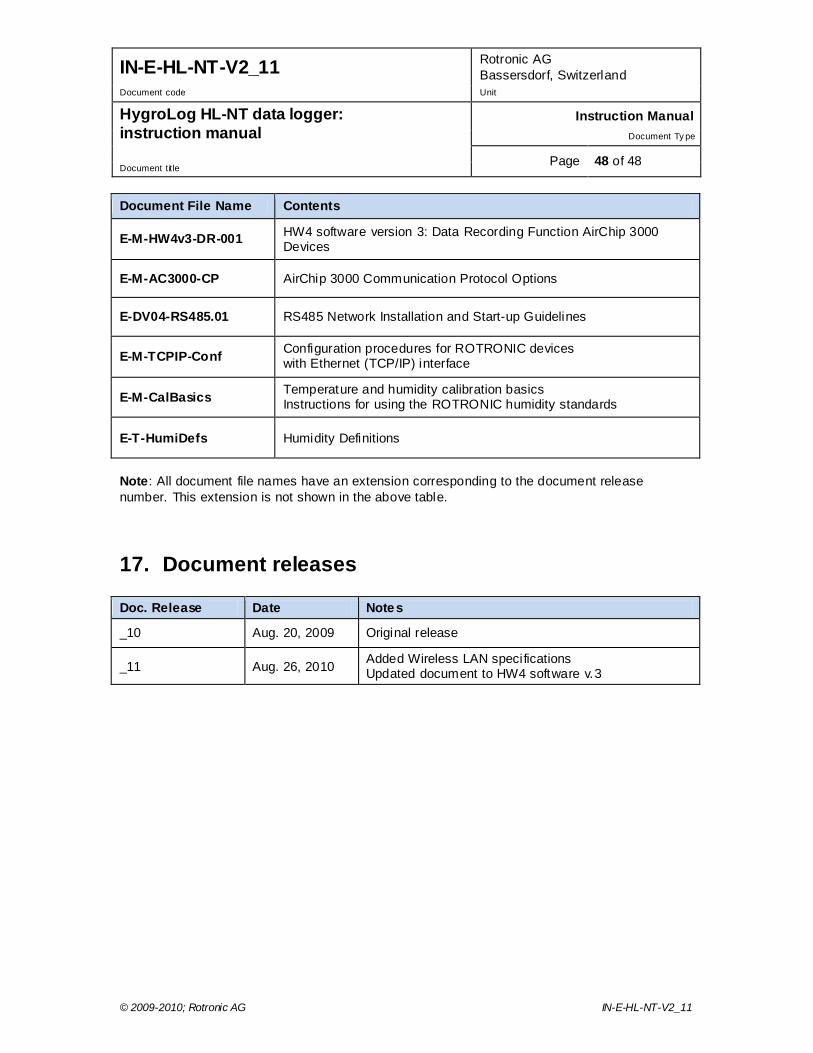
IN-E-HL-NT-V2_11 Rotronic AG Bassersdorf, Switzerland
Document code Unit
HygroLog HL-NT data logger: instruction manual
Instruction Manual Document Ty pe
Page 48 of 48 Document title
© 2009-2010; Rotronic AG IN-E-HL-NT-V2_11
Document File Name Contents
E-M-HW4v3-DR-001 HW4 software version 3: Data Recording Function AirChip 3000 Devices
E-M-AC3000-CP AirChip 3000 Communication Protocol Options
E-DV04-RS485.01 RS485 Network Installation and Start-up Guidelines
E-M-TCPIP-Conf Configuration procedures for ROTRONIC devices with Ethernet (TCP/IP) interface
E-M-CalBasics Temperature and humidity calibration basics Instructions for using the ROTRONIC humidity standards
E-T-HumiDefs Humidity Definitions
Note: All document file names have an extension corresponding to the document release number. This extension is not shown in the above table.
17. Document releases Doc. Release Date Notes
_10 Aug. 20, 2009 Original release
_11 Aug. 26, 2010 Added Wireless LAN specifications Updated document to HW4 software v.3