hypersonic vehicle flight dynamics with coupled...
TRANSCRIPT

IntegratedHypersonic
Vehicle Model
Dalle et al.
IntroductionApproach
Vehicle
Components
ModelPropulsive
Aerodynamic
ResultsPerformance
Trim
Interactions
Conclusions
AppendixVehicle
Gas model
Code descriptions
References
Hypersonic Vehicle FlightDynamics with Coupled
Aerodynamics andReduced-order Propulsive
ModelsAIAA Atmospheric Flight Mechanics
Conference
Derek J. Dalle, Scott G. V. Frendreis, James F. Driscoll, Carlos E. S.Cesnik
July 31, 2010
CCCS
Integrated Hypersonic Vehicle Model, AFM 2010 1/31

IntegratedHypersonic
Vehicle Model
Dalle et al.
IntroductionApproach
Vehicle
Components
ModelPropulsive
Aerodynamic
ResultsPerformance
Trim
Interactions
Conclusions
AppendixVehicle
Gas model
Code descriptions
References
Overview
Motivation
Flight dynamics analysis forhypersonic vehicle
Use in control design andevaluation simulations
Six degrees of freedom
Goals
Technique independent of vehicle
Combine previous analysis codes
Trim vehicle for specifiedcondition
Future goals
Aerothermoelastic considerations
Distributable code
Two-dimensional vehicle geometry
Three-dimensional vehicle geometry
CCCS
Integrated Hypersonic Vehicle Model, AFM 2010 2/31

IntegratedHypersonic
Vehicle Model
Dalle et al.
IntroductionApproach
Vehicle
Components
ModelPropulsive
Aerodynamic
ResultsPerformance
Trim
Interactions
Conclusions
AppendixVehicle
Gas model
Code descriptions
References
Available models
HSV
Compiled at AFRL by Bolender,M. A. and Doman, D. B.
Simplified but fairly completemodel of completetwo-dimensional vehicle
Automatic vehicle trim
Aerodynamic models
Easily extensible to 3D vehicles
Compute quickly
Very compatible with type ofgeometry we intend to use
MASIV (Michigan-AFRL Scramjet In Vehicle)
Two-dimensional propulsion analysis code for wide class of vehicles
Produced by group at Michigan
Includes inlet and nozzle
Quasi-steady rigid body models
2.75
0.75
Origin (0,0)
2.12 1.005.368.15 1.78 3.60
2.75
5.40
1.830.11
Combustor/isolatorheight
CCCS
Integrated Hypersonic Vehicle Model, AFM 2010 3/31

IntegratedHypersonic
Vehicle Model
Dalle et al.
IntroductionApproach
Vehicle
Components
ModelPropulsive
Aerodynamic
ResultsPerformance
Trim
Interactions
Conclusions
AppendixVehicle
Gas model
Code descriptions
References
Integration method
Overview
Goal is to replace and improve HSV
Incorporate MASIV for propulsion analysis and local inclination methodsfor aerodynamics
Separate vehicle into regions to be handled by appropriate models
Multiple 2D propulsion simulations with spanwise numerical integration
Challenge
Three-dimensional vehicle andtwo-dimensional code
Inlet and nozzle integral parts ofpropulsion system
Region determination and 2Dgeometry determination
Approach
Limit to vehicles with flat inletsand nozzles
Isolate inlet, combustor, andnozzle from rest of vehicle
Locate edges of cowl and tracealong surface of vehicle
CCCS
Integrated Hypersonic Vehicle Model, AFM 2010 4/31

IntegratedHypersonic
Vehicle Model
Dalle et al.
IntroductionApproach
Vehicle
Components
ModelPropulsive
Aerodynamic
ResultsPerformance
Trim
Interactions
Conclusions
AppendixVehicle
Gas model
Code descriptions
References
Vehicle geometry
Source
Part of TSTO geometry
Provided by VSIVogel, J. M., Kelkar, A. G., Inger, G.,Whitmer, C., Sidlinger, A., andRodriguez, A., “Control-RelevantModeling of Hypersonic Vehicles,” 2009American Control Conference.
Model
Hypersonic vehiclewith triangularelements
4634 nodes
9046 faces
Vehicle length is 46 m
Isometric view of vehicle
CCCS
Integrated Hypersonic Vehicle Model, AFM 2010 5/31
IntegratedHypersonic
Vehicle Model
Dalle et al.
IntroductionApproach
Vehicle
Components
ModelPropulsive
Aerodynamic
ResultsPerformance
Trim
Interactions
Conclusions
AppendixVehicle
Gas model
Code descriptions
References
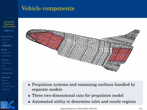
Vehicle components
Propulsion systems and remaining surfaces handled byseparate modelsThree two-dimensional cuts for propulsion modelAutomated utility to determine inlet and nozzle regions
CCCS
Integrated Hypersonic Vehicle Model, AFM 2010 6/31

IntegratedHypersonic
Vehicle Model
Dalle et al.
IntroductionApproach
Vehicle
Components
ModelPropulsive
Aerodynamic
ResultsPerformance
Trim
Interactions
Conclusions
AppendixVehicle
Gas model
Code descriptions
References
Propulsion geometry
15.54 m
3.41 m1.82 m 1.62 m
8.92 m
4.74 m2.78 m
21.24 m
Centerline propulsive geometry
3.34 m 4.74 m
7.47 m
1.76 m 1.62 m
8.92 m
2.78 m
21.24 m
Edge propulsive geometry
Two-dimensional model for entire propulsive system including inlet andnozzle
Considered at two locations to model three-dimensional vehicle
Geometries correspond to the dotted blue lines on the previous slide
CCCS
Integrated Hypersonic Vehicle Model, AFM 2010 7/31

IntegratedHypersonic
Vehicle Model
Dalle et al.
IntroductionApproach
Vehicle
Components
ModelPropulsive
Aerodynamic
ResultsPerformance
Trim
Interactions
Conclusions
AppendixVehicle
Gas model
Code descriptions
References
Canonical vehicle for propulsive model
8 1a 1b1c
1d 2a 3a 4a 4b 5a 6a
Several inlet ramps for compression efficiencyArbitrarily shaped, variable-area ductFuel injection trough any number of portsJet mixing in combustorNozzle with recombination and external expansion
CCCS
Integrated Hypersonic Vehicle Model, AFM 2010 8/31

IntegratedHypersonic
Vehicle Model
Dalle et al.
IntroductionApproach
Vehicle
Components
ModelPropulsive
Aerodynamic
ResultsPerformance
Trim
Interactions
Conclusions
AppendixVehicle
Gas model
Code descriptions
References
2D aerodynamic model (SAMURI)
Supersonic Aerodynamic ModelUsing Riemann Interactions
Uses oblique shock theory
Discrete expansion waves
Arbitrary number of waveinteractions
Accounts for calorically imperfectgas
Any geometry with no detachedwaves
Two diamond airfoils in M∞ = 2, α = 0 flow
Sample inlet geometry at M∞ = 8
CCCS
Integrated Hypersonic Vehicle Model, AFM 2010 9/31

IntegratedHypersonic
Vehicle Model
Dalle et al.
IntroductionApproach
Vehicle
Components
ModelPropulsive
Aerodynamic
ResultsPerformance
Trim
Interactions
Conclusions
AppendixVehicle
Gas model
Code descriptions
References
Modified shock-expansion theory
Calculate the pressure on each panel
Include angular velocity of each panel
~v =~v∞ +~ω×~r
Find deflection angle
sinδ =− n̂ ·~v‖~v‖
Use Prandtl-Meyer theory if δ < 0 and shock if δ > 0
p = p∞
(2γ
γ + 1M2 sin2
β− γ−1γ + 1
)If δ≤ δmax, i.e. there can be an attached shock, use oblique shock relation
tanδ = 2cotβM2 sin2
β−1M2(γ + cos2β) + 2
If shock is detached, interpolate the shock angle
β = βmax +δ−δmax
π/2−δmax(π/2−βmax)
CCCS
Integrated Hypersonic Vehicle Model, AFM 2010 10/31
IntegratedHypersonic
Vehicle Model
Dalle et al.
IntroductionApproach
Vehicle
Components
ModelPropulsive
Aerodynamic
ResultsPerformance
Trim
Interactions
Conclusions
AppendixVehicle
Gas model
Code descriptions
References
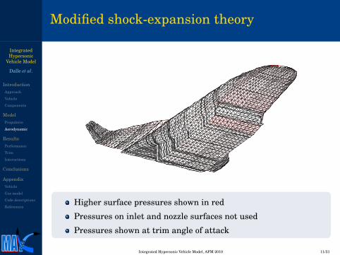
Modified shock-expansion theory
Higher surface pressures shown in red
Pressures on inlet and nozzle surfaces not used
Pressures shown at trim angle of attack
CCCS
Integrated Hypersonic Vehicle Model, AFM 2010 11/31

IntegratedHypersonic
Vehicle Model
Dalle et al.
IntroductionApproach
Vehicle
Components
ModelPropulsive
Aerodynamic
ResultsPerformance
Trim
Interactions
Conclusions
AppendixVehicle
Gas model
Code descriptions
References
Performance of propulsive components
01
2
3
0
2
40
500
1000
1500
2000
Φα [◦]
Fx[kN]
Installed thrust
01
2
3
0
2
41000
1500
2000
2500
3000
Φα [◦]
Fz[kN]
Lift from inlet and nozzle
Includes inlet, combustor, and nozzle
High equivalence ratios due to poor mixing
Jagged performance caused by wave interactions
CCCS
Integrated Hypersonic Vehicle Model, AFM 2010 12/31

IntegratedHypersonic
Vehicle Model
Dalle et al.
IntroductionApproach
Vehicle
Components
ModelPropulsive
Aerodynamic
ResultsPerformance
Trim
Interactions
Conclusions
AppendixVehicle
Gas model
Code descriptions
References
Trim methodology
Cost function
Minimization approach to trim
Eliminate net forces and moments
J =[~FB ~NB
]W
[~FB~NB
]Continuous optimization technique
Control variables
Fuel-air equivalence ratio
Elevator angle
Surrogate model
Propulsive model has some discontinuities
Used a curve-fit model for propulsive model
Maintained full model for aerodynamic model
CCCS
Integrated Hypersonic Vehicle Model, AFM 2010 13/31

IntegratedHypersonic
Vehicle Model
Dalle et al.
IntroductionApproach
Vehicle
Components
ModelPropulsive
Aerodynamic
ResultsPerformance
Trim
Interactions
Conclusions
AppendixVehicle
Gas model
Code descriptions
References
Trim states
State Name Surrogate Full model‖~vB‖ Velocity magnitude 2.40 km/s 2.40 km/s−zE Altitude 26 km 26 km
α Angle of attack 2.89 deg 2.86 degβ Sideslip angle 0 deg 0 degθ Pitch Euler angle 2.89 deg 2.86 degφ Roll Euler angle 0 deg 0 deg
v̇B,x x-component of~̇vB −1.87×10⁻⁵ m/s2 4.28×10⁻¹ m/s2
v̇B,z z-component of~̇vB 1.45×10⁻⁵ m/s2 8.89×10⁻⁵ m/s2
ω̇B,y y-component of ~̇ωB −1.52×10⁻⁸ rad/s2 −1.59×10⁻⁶ rad/s2
δe Elevator deflection angle 26.9 deg 27.4 degΦ Equivalence ratio 1.73 1.95
Extra thrust in full model
Similar results for control variables
Using state obtained from surrogate model did not give trimmed flightusing the full model
Very large elevator angles
CCCS
Integrated Hypersonic Vehicle Model, AFM 2010 14/31

IntegratedHypersonic
Vehicle Model
Dalle et al.
IntroductionApproach
Vehicle
Components
ModelPropulsive
Aerodynamic
ResultsPerformance
Trim
Interactions
Conclusions
AppendixVehicle
Gas model
Code descriptions
References
Inlet flow near trim state
Darker shades of blue representhigher temperatures
Maximum temperature of 780 K
Compression ratio of p2/p∞ = 6.77(edge) and p2/p∞ = 4.50 (center)
Shock completely goes intoengine Inlet temperature at left or right edge
Inlet temperature contours along centerline
CCCS
Integrated Hypersonic Vehicle Model, AFM 2010 15/31

IntegratedHypersonic
Vehicle Model
Dalle et al.
IntroductionApproach
Vehicle
Components
ModelPropulsive
Aerodynamic
ResultsPerformance
Trim
Interactions
Conclusions
AppendixVehicle
Gas model
Code descriptions
References
Nozzle profile near trim state
Temperatureprofiles
Maximumtemperature of1600 K
Divergent plume
Notice shockcoming off of plume
Fairly symmetric
None of the wavesin the nozzle willcause huge jumpsin performancewith small changesin flightparameters
Edge nozzle profile
Centerline nozzle profile
CCCS
Integrated Hypersonic Vehicle Model, AFM 2010 16/31

IntegratedHypersonic
Vehicle Model
Dalle et al.
IntroductionApproach
Vehicle
Components
ModelPropulsive
Aerodynamic
ResultsPerformance
Trim
Interactions
Conclusions
AppendixVehicle
Gas model
Code descriptions
References
Robust inlet optimization
Single-condition designApparently excellent performanceat one conditionDifficult/impossible to control(high sensitivities)Performance curve is jaggedNarrow operating range
Range of conditionsOperating range specified as partof designPerformance curves smoothwithin that range
improved design
single-condition design
6 7 8 9 100.3
0.4
0.5
0.6
0.7
0.8
M¥
p 0,2
�p 0
,¥
single-condition design
improved design
6 7 8 9 10
40
50
60
70
M¥
p 2�p ¥
CCCS
Integrated Hypersonic Vehicle Model, AFM 2010 17/31

IntegratedHypersonic
Vehicle Model
Dalle et al.
IntroductionApproach
Vehicle
Components
ModelPropulsive
Aerodynamic
ResultsPerformance
Trim
Interactions
Conclusions
AppendixVehicle
Gas model
Code descriptions
References
Additional applications
Design tools
Numerous suggestedimprovements for vehicle
Extensive design tools for 2Dpropulsion code exist
Would like to be able to use codeto design a vehicle for a specificrange of flight conditions
Automation
Eliminate reliance on surrogatemodels
Smoother performance ofpropulsion system
More robust numerical methodfor trim
Flight envelope
Find flight conditions where thevehicle can be trimmed
Ranges of flight Mach numberand altitude
Requires method to determinethat trim is not possible
CCCS
Integrated Hypersonic Vehicle Model, AFM 2010 18/31

IntegratedHypersonic
Vehicle Model
Dalle et al.
IntroductionApproach
Vehicle
Components
ModelPropulsive
Aerodynamic
ResultsPerformance
Trim
Interactions
Conclusions
AppendixVehicle
Gas model
Code descriptions
References
Conclusions
Reduced-order model
2D propulsive model
3D aerodynamic model
Automatic integration of models
All performed in MATLAB
Trim analysis
Excess thrust using full model
Constructed surrogate forpropulsive model
Able to trim with about 3 hrs ofcomputation
Large elevator deflection angle
Large equivalence ratio
Vehicle design
Reduce nose-down moment
Higher compression in inlet
Larger control surfaces
Narrower combustor
Necessary improvements
Smoother propulsion model
Aeroelastic analysis
Thermal analysis
Automated design tools
More robust trim method
Turn into a distributable code
CCCS
Integrated Hypersonic Vehicle Model, AFM 2010 19/31

IntegratedHypersonic
Vehicle Model
Dalle et al.
IntroductionApproach
Vehicle
Components
ModelPropulsive
Aerodynamic
ResultsPerformance
Trim
Interactions
Conclusions
AppendixVehicle
Gas model
Code descriptions
References
Acknowledgments
MACCCS group, Sean M. Torrez, Matt L. Fotia, TorstensSkujins, Nate FalkiewiczAFRL/AFOSR, Michael W. Oppenheimer, MichaelA. Bolender, David B. DomanVSI AerospaceThis research was supported by U.S. Air Force ResearchLaboratory grant FA 8650-07-2-3744 for the Michigan AirForce Research Laboratory Collaborative Center forControl Science.This research was also supported by NASA grantNNX08AB32A, administered by Donald Soloway andJorge Bardina, technical monitors.
CCCS
Integrated Hypersonic Vehicle Model, AFM 2010 20/31

IntegratedHypersonic
Vehicle Model
Dalle et al.
IntroductionApproach
Vehicle
Components
ModelPropulsive
Aerodynamic
ResultsPerformance
Trim
Interactions
Conclusions
AppendixVehicle
Gas model
Code descriptions
References
Vehicle inertia properties
Symbol Name Valuem Mass 2.22×10⁵ kgIxx Moment of inertia about x-axis 3.42×10⁶ kg ·m2
Iyy Moment of inertia about y-axis 3.95×10⁷ kg ·m2
Izz Moment of inertia about z-axis 3.95×10⁷ kg ·m2
Ixy Product of inertia 0 kg ·m2
Ixz Product of inertia 0 kg ·m2
Iyz Product of inertia 0 kg ·m2
CCCS
Integrated Hypersonic Vehicle Model, AFM 2010 21/31

IntegratedHypersonic
Vehicle Model
Dalle et al.
IntroductionApproach
Vehicle
Components
ModelPropulsive
Aerodynamic
ResultsPerformance
Trim
Interactions
Conclusions
AppendixVehicle
Gas model
Code descriptions
References
Shock/expansion theory
Oblique shocksPerfect-gas obliqueshock analyticsolutiona
Cubic polynomial forsinβ where β is thewave angleThree solutions
Weak oblique shockStrong oblique shockEntropy-destroyingshock
aThompson, M. J. “A Note on theCalculation of Oblique Shock WaveCharacteristics.” Journal ofAerospace Sciences. 1950 vol. 27,pp. 741-744
control volume A
control volume B
Illustration of two control volumes around a diamond airfoil
Net fluxes into A must be the sameas net fluxes into BDrag is not a function of the controlvolume used to compute it
CCCS
Integrated Hypersonic Vehicle Model, AFM 2010 22/31

IntegratedHypersonic
Vehicle Model
Dalle et al.
IntroductionApproach
Vehicle
Components
ModelPropulsive
Aerodynamic
ResultsPerformance
Trim
Interactions
Conclusions
AppendixVehicle
Gas model
Code descriptions
References
The case for expansion shocks
Discrete expansions
Finite-strength waves aredifferent from continuousexpansionsOne degree of freedom (waveangle) and three constraints(mass and momentumconservation)
Solution
Use downstream state forextra degrees of freedomLeads exactly to the obliqueshock conditionsStill accurate if expansionsare split into several shocks
Control volume
Control volume around an expansion withnexp = 1
Net mass/momentum fluxinto control volume must bezeroSame for any other controlvolume that does not crossthe surface
CCCS
Integrated Hypersonic Vehicle Model, AFM 2010 23/31

IntegratedHypersonic
Vehicle Model
Dalle et al.
IntroductionApproach
Vehicle
Components
ModelPropulsive
Aerodynamic
ResultsPerformance
Trim
Interactions
Conclusions
AppendixVehicle
Gas model
Code descriptions
References
Discretized expansion waves
DiscretizationMakes conditions a piecewiseconstant function of angleUsing angles based on Guassianquadrature minimizes∫
σA
σB
(M(σ)− M̃(σ))2 dσ
Puts waves near edges of expansionGoal is to keep accuracy high andnexp low
ConservationUse expansion shocksEstimate of state B will be slightlyinaccurate
σ
A
B
Smooth expansion with δ = 18.4◦and M∞ = 1.5
Sample expansion with nexp = 4
CCCS
Integrated Hypersonic Vehicle Model, AFM 2010 24/31

IntegratedHypersonic
Vehicle Model
Dalle et al.
IntroductionApproach
Vehicle
Components
ModelPropulsive
Aerodynamic
ResultsPerformance
Trim
Interactions
Conclusions
AppendixVehicle
Gas model
Code descriptions
References
Riemann problem
Discontinuous regionscome in contact whenshocks intersectRegions B and C musthave the same pressureDensity and temperaturemay differFlow matches directionWaves separate regions Afrom B and D from CMain limiter of codeperformance
Zoom in on a generic flow
A
B
C
D
ΘB
ΘA
ΘD
ΣA
ΒA
ΣD
ΣC
ΜD
ΜC
Sketch of two interacting waves.
CCCS
Integrated Hypersonic Vehicle Model, AFM 2010 25/31

IntegratedHypersonic
Vehicle Model
Dalle et al.
IntroductionApproach
Vehicle
Components
ModelPropulsive
Aerodynamic
ResultsPerformance
Trim
Interactions
Conclusions
AppendixVehicle
Gas model
Code descriptions
References
Comparison of SAMURI and CFD
Results from CFD++.
Results from reduced-order model.
Pressure contours; darkest is p/p∞ = 90
Maximum error is about 6%
CFD model included viscosity
CCCS
Integrated Hypersonic Vehicle Model, AFM 2010 26/31

IntegratedHypersonic
Vehicle Model
Dalle et al.
IntroductionApproach
Vehicle
Components
ModelPropulsive
Aerodynamic
ResultsPerformance
Trim
Interactions
Conclusions
AppendixVehicle
Gas model
Code descriptions
References
The Michigan/AFRL Scramjet In Vehicle code
InletWave interactions solved using exact solutionExpansions discretizedArbitrary number of distinct regions tracked
CombustorRealistic fuel-air mixing from jet lawsFinite-rate chemistry pre-tabulated from flamelet solutionsVariable fuel injection and duct area changeWill incorporate isolator to cover ram/scram transition
NozzleUses same aerodynamic model as inletUses conditions from combustor (can be non-uniform)Incorporates finite-rate chemistry
CCCS
Integrated Hypersonic Vehicle Model, AFM 2010 27/31

IntegratedHypersonic
Vehicle Model
Dalle et al.
IntroductionApproach
Vehicle
Components
ModelPropulsive
Aerodynamic
ResultsPerformance
Trim
Interactions
Conclusions
AppendixVehicle
Gas model
Code descriptions
References
Propulsion model code description
MASIV Data flow
Inlet Combustor Nozzle
SAMURI SAMURI
Force/Moment
Design
Conditions
SolutionOptions
Station 2
Options SolutionStation 5
MASIV
User only interacts with green blocksDefault vehicle design provided
CCCS
Integrated Hypersonic Vehicle Model, AFM 2010 28/31

IntegratedHypersonic
Vehicle Model
Dalle et al.
IntroductionApproach
Vehicle
Components
ModelPropulsive
Aerodynamic
ResultsPerformance
Trim
Interactions
Conclusions
AppendixVehicle
Gas model
Code descriptions
References
2D Aerodynamic Model
SAMURI data flow
Geometry
Preprocess
Set x = xmin
Geometryand states
Set y = ymin
Update wavepositions
x = xmax
no
Find next x y = ymaxyes
Find next y
no
Find type ofinteraction
Solve
Wait forexit signalExit
yes
Output
Conditions
Basically a sweep through the flow domainOnly works for supersonic flowAll of the flow physics in the “Solve” block
CCCS
Integrated Hypersonic Vehicle Model, AFM 2010 29/31

IntegratedHypersonic
Vehicle Model
Dalle et al.
IntroductionApproach
Vehicle
Components
ModelPropulsive
Aerodynamic
ResultsPerformance
Trim
Interactions
Conclusions
AppendixVehicle
Gas model
Code descriptions
References
Bibliography
Korte, J. J., “Parametric Model of an Aerospike Rocket Engine,” 38thAerospace Sciences Meeting, AIAA Paper 2000-1044, 2000.
McBride, B. J., Zehe, M. J., and Gordon, S., “NASA Glenn Coefficients forCalculating Thermodynamic Properties of Individual Species,” NASATechnical Paper 2002-211556, 2001.
Bolender, M. A. and Doman, D. B., “Nonlinear Longitudinal DynamicalModel of an Air-Breathing Hypersonic Vehicle,” Journal of Spacecraftand Rockets, Vol. 44, No. 2, 2007, pp. 374-387.
Chavez, F. R. and Schmidt, D. K., “Analytical Aeropropulsive/AeroelasticHypersonic-Vehicle Model with Dynamic Analysis,” Journal of Guidance,Control, and Dynamics, Vol. 17, No. 6, 1994, pp. 1308-1319.
O’Brien, T. F., Starkey, R. P., and Lewis, M. J., “Quasi-One-DimensionalHigh-Speed Engine Model with Finite-Rate Chemistry,” Journal ofPropulsion and Power, Vol. 17, No. 6, 2001, pp. 1366-1374.
Higgins, K. and Schmidt, S., “Simulation of a Sonic Jet Injected into aSupersonic Cross-Flow,” 16th Australasian Fluid Mechanics Conference,2007.
CCCS
Integrated Hypersonic Vehicle Model, AFM 2010 30/31

IntegratedHypersonic
Vehicle Model
Dalle et al.
IntroductionApproach
Vehicle
Components
ModelPropulsive
Aerodynamic
ResultsPerformance
Trim
Interactions
Conclusions
AppendixVehicle
Gas model
Code descriptions
References
Papers by our group
Dalle, D. J., Fotia, M. L., and Driscoll, J. F., “Reduced-Order Modeling ofTwo-Dimensional Supersonic Flows with Applications to ScramjetInlets,” Journal of Propulsion and Power, Vol. 26, No. 3, 2010, pp.545-555.
Frendreis, S. G. V., Skujins, T., and Cesnik, C. E. S.,“Six-Degree-of-Freedom Simulation of Hypersonic Vehicles,” AIAAAtmospheric Flight Mechanics Conference & Exhibit, 2009, AIAA Paper2009-5601.
Torrez, S. M., Driscoll, J. F., Dalle, D. J., and Fotia, M. L., “PreliminaryDesign Methodology for Hypersonic Engine Flowpaths,” 16thAIAA/DLR/DGLR/ International Space Planes and Hypersonic Systemsand Technologies Conference, 2009, AIAA Paper 2009-7289.
Dalle, D. J., Torrez, S. M., and Driscoll, J. F., “Reduced-Order Modeling ofReacting Supersonic Flows in Scramjet Nozzles,” 46thAIAA/ASME/SAE/ASEE Joint Propulsion Conference and Exhibit,2010.
Frendreis, S. G. V., and Cesnik, C. E. S., “3D Simulation of a FlexibleHypersonic Vehicle,” AIAA Atmospheric Flight Mechanics Conference &Exhibit, 2010.
CCCS
Integrated Hypersonic Vehicle Model, AFM 2010 31/31