hyundai-beta-l4gc 2003.pdf
TRANSCRIPT
1. GENERAL .......................................................................... 1- 1
2. RECOMMENDED LUBRICANTS AND CAPACITIES ........... 1- 5
3. SCHEDULED MAINTENANCE............................................ 1- 6
CHAPTER 1. GENERAL

1-1
ENGINE IDENTIFICATION NUMBERThe engine identification number consists of 11 digits.
1. Engine fuelL : LPG
2. Engine range4 : In line 4 cycle 4 cylinder
3. Engine development orderG : engine
4. Engine capacityC: 1975 CC ( engine)
5. Production year1 : 2001 2 : 2002 3 : 20034 : 2004 5 : 2005 6 : 2006
6. Engine production sequence number000001 ~ 999999
GENERAL
L 4 G C X 0 0 0 0 0 1
1 2 3 4 5 6
ENGINE IDENTIFICATION NUMBER LO-CATIONThe engine identification number is stamped on the left side ofthe top edge of the exhaust manifold cylinder block.
L4GC540411?
L4GC200A

1-2
SAFETY NOTICE1. REMOVING AND DISASSEMBLING
After finding the malfunctioning reason and determining theremoval and disassembly if necessary, simultaneously withchecking the defect parts, start the job as the instruction ofthe shop manual.To prevent mal-assembly and to ease job, put punch marksor identification marks on the places where not affect nor-mal function and exterior.Arrange multi-piece parts and similar parts in order whendisassembling not to make a mistake while reassembling.
1) Arrange the removed parts in order.2) Sort replacement parts and re-use parts3) When replacing bolts and nuts, necessarily use the
specified standard parts.
GENERAL
3. REPLACEMENT PARTSThe following parts should be replaced with new parts afterremoving.
1) Oil seal2) Gasket (except the locker cover gasket)3) Packing4) O-ring5) Locker washer6) Split pin
L4GC202A
L4GC203A
L4GC201A
2. SPECIAL TOOLNecessarily use the special tool as instruction to preventparts from damage as result of using other general tool.

1-3
4. PARTS
1) When replacing parts, necessarily use the Hyundai genu-ine parts.
2) It is recommended to use spare parts prepared in theset or kit.
3) Spare parts can be different from actual assembled partsas the result of parts unification, so start the job afterchecking the parts catalog
GENERAL
Certificate (attached) Certificate (removed)
Genuine parts
L4GC204A
1-4 GENERAL
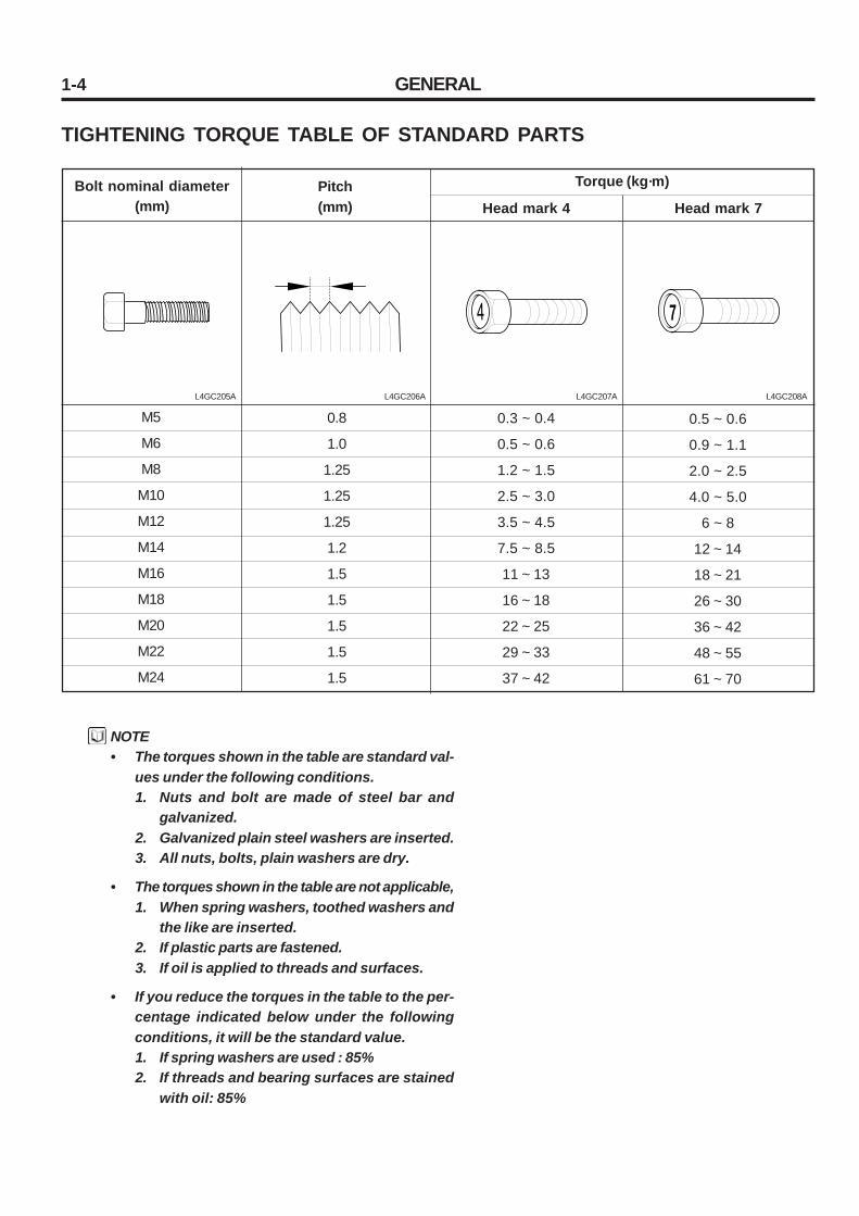
TIGHTENING TORQUE TABLE OF STANDARD PARTS
NOTE• The torques shown in the table are standard val-
ues under the following conditions.1. Nuts and bolt are made of steel bar and
galvanized.2. Galvanized plain steel washers are inserted.3. All nuts, bolts, plain washers are dry.
• The torques shown in the table are not applicable,1. When spring washers, toothed washers and
the like are inserted.2. If plastic parts are fastened.3. If oil is applied to threads and surfaces.
• If you reduce the torques in the table to the per-centage indicated below under the followingconditions, it will be the standard value.1. If spring washers are used : 85%2. If threads and bearing surfaces are stained
with oil: 85%
Head mark 7
0.5 ~ 0.6
0.9 ~ 1.1
2.0 ~ 2.5
4.0 ~ 5.0
6 ~ 8
12 ~ 14
18 ~ 21
26 ~ 30
36 ~ 42
48 ~ 55
61 ~ 70
Head mark 4Bolt nominal diameter
(mm)
0.3 ~ 0.4
0.5 ~ 0.6
1.2 ~ 1.5
2.5 ~ 3.0
3.5 ~ 4.5
7.5 ~ 8.5
11 ~ 13
16 ~ 18
22 ~ 25
29 ~ 33
37 ~ 42
0.8
1.0
1.25
1.25
1.25
1.2
1.5
1.5
1.5
1.5
1.5
M5
M6
M8
M10
M12
M14
M16
M18
M20
M22
M24
Torque (kg·m)Pitch(mm)
L4GC205A L4GC206A L4GC207A L4GC208A
1-5RECOMMENDED LUBRICANTS AND CAPACITIES
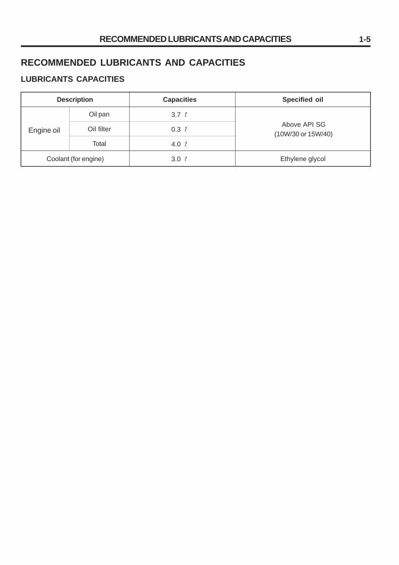
RECOMMENDED LUBRICANTS AND CAPACITIESLUBRICANTS CAPACITIES
Engine oil
Description Capacities
Oil pan
Oil filter
Total
Specified oil
Above API SG(10W/30 or 15W/40)
Coolant (for engine)
3.7
0.3
4.0
3.0 Ethylene glycol

1-6 SCHEDULED MAINTENANCE
SCHEDULED MAINTENANCEENGINE OIL CLASSIFICATION
Recommended API classification: Above SG
Recommended SAE viscosity classification
The following lubricants should be selected for all engines toenhance excellent performance and maximum effect.
1. Observe the API classification guide.
2. Proper SAE classification number should be selected withinambient temperature ranges. Do not use the lubricant withSAE classification number and API grade not identified onthe container.
L4GC209A
-7
-13
-18
-30
10W 5W
-20
(5W*1-30)
-50
20W
-40
15W
˚C
*1 : 5W-20 engine oil is recommended for everywhere If 5W-20 is not applicable, 5W-30 or proper engine oil according to temperature ranges will be possible.
Applied temperature range until replacement
Recommended SAE viscosity number
1-7SCHEDULED MAINTENANCE
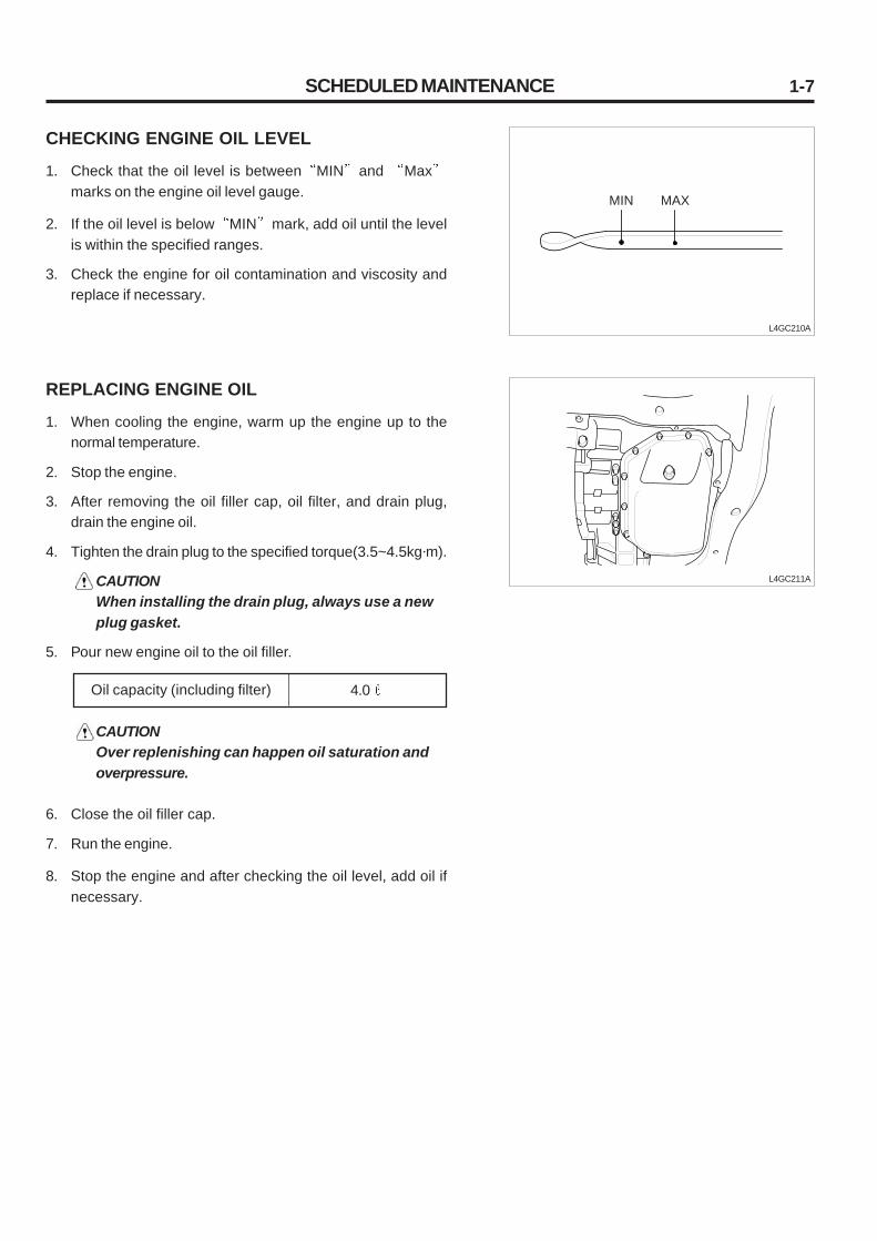
REPLACING ENGINE OIL
1. When cooling the engine, warm up the engine up to thenormal temperature.
2. Stop the engine.
3. After removing the oil filler cap, oil filter, and drain plug,drain the engine oil.
4. Tighten the drain plug to the specified torque(3.5~4.5kg·m).
CAUTIONWhen installing the drain plug, always use a newplug gasket.
5. Pour new engine oil to the oil filler.
L4GC211A
Oil capacity (including filter) 4.0
CAUTIONOver replenishing can happen oil saturation andoverpressure.
6. Close the oil filler cap.
7. Run the engine.
8. Stop the engine and after checking the oil level, add oil ifnecessary.
CHECKING ENGINE OIL LEVEL
1. Check that the oil level is between MIN and Maxmarks on the engine oil level gauge.
2. If the oil level is below MIN mark, add oil until the levelis within the specified ranges.
3. Check the engine for oil contamination and viscosity andreplace if necessary.
L4GC210A
MIN MAX

1-8
REPLACING ENGINE OIL FILTER
1. Remove the oil filter using a filter wrench.
2. When installing new parts, after applying engine oil to theO-ring, tighten the oil filter securely by hand.
3. Tighten the oil filter to the specified torque.
4. Start the engine and inspect the oil leak. L4GC212A
L4GC213A
L4GC303A
SCHEDULED MAINTENANCE
Oil filter 1.2 ~ 1.6 kg·m
CHECKING DRIVE BELT TENSION
1. Press the middle of the water pump pulley and alternatorpulley with 10kg·f.
2. Inspect the belt deflection by pressing it.
3. If the belt deflection is out of the standard, adjust it asfollows.
ItemStandard
Drive belt deflection 4.0 ~ 4.4mm
New belt Used belt5.1 ~ 5.7mm
CHECKING SPARK PLUG
INSPECTION
1. Remove the spark plug from the cylinder head using a sparkplug wrench.
CAUTIONPrevent foreign material from getting in the sparkplug fitting hole.
2
3 4 5
1
2. Check the following items of the spark plug.
1) Damage of the insulator2) Wear of the terminal3) Carbon deposits4) Damage of the gasket5) Porcelain insulator in the spark plug clearance

1-9
3. Check the plug clearance using a plug clearance gauge andif the value is not within the specified values, adjust it bybending the ground clearance.When installing a new spark plug, install it after checkingthe uniform plug clearance.
SCHEDULED MAINTENANCE
L4GC304A
Spark plug clearance 0.7 ~ 0.8mm
4. Install the spark plug and tighten it to the specified torque.Take care not to over tighten it to prevent cylinder headthreads from damage.
State Contact point is black Contact point is white
SPARK PLUG TEST
After connecting the spark plug to the ignition coil, connect theouter terminal(main body) to the ground and crank the engine.Because the discharging clearance is narrow in the air, onlyslight spark will arise. But if the spark plug is defect, sparkdoes not arise because insulation is damaged.
L4GC217A
Clearance
SPARK PLUG ANALYSIS
Description Density of the fuel mixture is thick
Lack of air intake
Density of the fuel mixture is thin
Ignition timing is fastSpark plug is tightLack of torque
Insulation damaged
Insulation damaged
Insulation damaged

1-10
REPLACING OXYGEN SENSOR
Oxygen sensor is as a fuel mixture control unit, if it is damaged,exhaust gas will be bad as well as engine performance. So, ifthe oxygen sensor is defected, necessarily replace it.
L4GC215A
COOLING SYSTEM
Check the cooling system hoses for damage and looseness orinspect the joints for coolant leaks.
COOLANT
When the engine is delivered, the engine cooling system con-tains mixture of antifreeze(40%) and water(60%).Because the cylinder head and the water pump are made ofaluminum alloy, the mixture should contain antifreeze (ethyleneglycol) of 30~60% to prevent those from corrosion, freezingand bursting.
NOTE• If the coolant contains less than 30% of antifreeze,
anticorrosion is decreased.• If the coolant contains more than 60% of
antifreeze, the engine will be fatally affected, re-sulting from decreased anti-freezing and enginecooling. Use only the recommended antifreezeand do not mix with other production.
Recommended antifreeze Ethylene glycol
SCHEDULED MAINTENANCE

1-11
COOLANT VISCOSITY MEASUREMENT
Run the engine until the coolant is mixed completely, drain alittle of coolant to determine the coolant viscosity at a safeoperating temperature, measure the coolant viscosity and ad-just it to the specified value.
REPLACING COOLANT
CAUTIONIf the coolant is hot, injury can happen, so when theengine is hot, never open the radiator cap until thecoolant temperature is dropped. When open the ra-diator cap, be careful of hot coolant or steam, sur-round the upper portion of the cap with a rag, slightlyopen it counterclockwise to drop the pressurethrough the reservoir tank tube, and then slowly turnthe cap to open.
1. After opening the radiator cap, loosen the drain plug and theengine drain plug and drain the coolant.
2. Remove the reservoir tank and drain the coolant.
3. After draining the coolant completely, close the drain plug,fill the engine and the radiator full with a radiator cleaner,and clean the engine and the radiator.
4. After completing the cleaning, drain the cleaner and closethe radiator and engine drain plug.
5. After running the engine for a while, inspect the coolantlevel and add a coolant to the specified level.
6. Replenish the reservoir tank with a coolant until the levelreads between FULL and LOW marks.
SCHEDULED MAINTENANCE
1. GENERAL ........................................................................ 2- 1
2. CYLINDER BLOCK .......................................................... 2-19
3. LUBRICATION SYSTEM ................................................... 2-22
4. MAIN MOVING SYSTEM ................................................... 2-28
5. COOLING SYSTEM .......................................................... 2-49
6. INTAKE AND EXHAUST SYSTEM .................................... 2-56
7. CYLINDER HEAD ASSEMBLY .......................................... 2-61
8. TIMING SYSTME .............................................................. 2-70
CHAPTER 2. ENGINE MECHANICAL SYSTEM
GENERAL 2-1
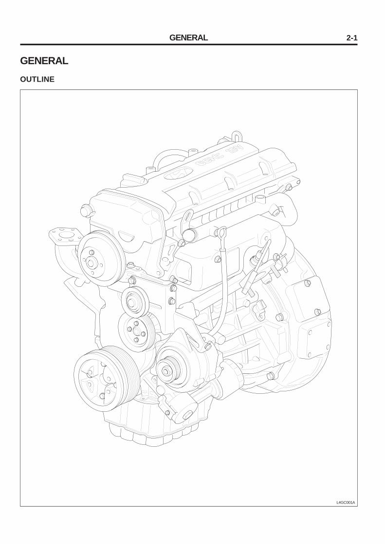
GENERALOUTLINE
L4GC001A

GENERAL2-2
L4GC002A

GENERAL 2-3
GENERALSPECIFICATIONS
LimitSpecification
GENERALTypeCylinder numberBoreStrokeDisplacementCompression ratioFiring orderRPMIgnition timingValve timing Intake Open Close Exhaust Open CloseValve over rap
CYLINDER HEADFlatness of gasket surfaceFlatness of manifold mounting surfaceOversize of valve seat hole Intake 0.3 OS 0.6 OS Exhaust 0.3 OS 0.6 OS Oversize of valve guide hole 0.05 OS 0.25 OS 0.50 OS
CAMSHAFTCam height Intake ExhaustJournal O.DBearing oil clearanceEnd play
Series, DOHC4
82 mm93.5 mm1,975 cc
9.41 - 3 - 4 - 2
700 100 rpmBTDC 8° 5 °
BTDC 2°ABDC 16°
BBDC 6°ATDC 2°
4 °
0.03 mm or less0.15 mm or less
33.3 ~ 33.325 mm33.6 ~ 33.625 mm
28.8 ~ 28.821 mm29.1 ~ 29.121 mm
11.05 ~ 11.069 mm11.25 ~ 11.268 mm11.50 ~ 11.518 mm
43 mm43 mm
280.02 ~ 0.061 mm
0.1 ~ 0.2 mm
Description
0.06 mm0.3 mm
0.2 mm
42.9 mm42.9 mm

GENERAL2-4
Description Specification Limit
VALVEStem O.D Intake ExhaustThickness of valve head (Margin) Intake ExhaustValve stem to guide clearance Intake Exhaust
VALVE GUIDELength Installed size Over size
VALVE SEATSeat angleOver size
VALVE SPRINGFree lengthLoad
Installed heightOut-of squareness
CYLINDER BLOCKCylinder I.DOut-of cylindricity of cylinder I.DCylinder block-to-piston clearance
PISTONO.DOver size
PISTON RINGSide clearance No.1 No.2End gap No.1 No.2 Oil ring side railOver size
CONNECTING RODBendTwistSide clearance
5.965 ~ 5.980 mm5.950 ~ 5.965 mm
1.15 mm1.35 mm
0.02 ~ 0.05 mm0.035 ~ 0.065 mm
Intake : 46, Exhaust : 54.50.05, 0.25, 0.50
45°0.3, 0.6
48.86 mm18.3kg/39 mm
40.0kg/30.5 mm39 mm
1.5 mm or less
82.00 ~ 82.03 mmLess than 0.01 mm
0.02 ~ 0.04
81.97 ~ 82.00 mm0.25, 0.50, 0.75, 1.00
0.04 ~ 0.08 mm0.03 ~ 0.07mm
0.23 ~ 0.38 mm0.33 ~ 0.48 mm0.2 ~ 0.6 mm
0.25, 0.50, 0.75, 1.00
0.05 mm or less0.10 mm or less
0.100 ~ 0.250 mm
0.8 mm1.0 mm
0.1 mm0.13 mm
3°
0.1 mm0.1 mm
1.0 mm1.0 mm1.0 mm
0.4 mm

GENERAL 2-5
CONNECTING ROD BEARINGOil clearanceUnder size
CRANKSHAFTPin O.DJournal O.DBendOut-of cylindricity of journal and pinEnd playUnder size of pin 0.25 0.50 0.75Under size of journal 0.25 0.50 0.75
OIL PUMPO.D-to-front case clearanceFront side clearance Tip clearance Outer gear Inner gearOil pressure (Oil temperature 90°C~100°C) at idle (800rpm)
RELIEF SPRINGFree heightLoad
Cooling type
Water pump typeThermostat typeAntifreeze viscosity
THERMOSTATValve open temperatureFully open temperature
WATER TEMPERATURE SENSORType Resistance(at 20°C)
0.024 ~ 0.044 mm0.25, 0.50, 0.75
45 mm57 mm
Less than 0.03 mmLess than 0.01 mm
0.06 ~ 0.260
44.725 ~ 44.740 mm44.475 ~ 44.490 mm44.225 ~ 44.240 mm
56.727 ~ 56.742 mm56.477 ~ 56.492 mm56.227 ~ 56.242 mm
0.12 ~ 0.185 mm
0.025 ~ 0.069 mm0.04 ~ 0.09 mm0.04 ~ 0.085 mm
1.7kg/cm2
43.8 mm3.7kg/40.1 mm
Water-cooled forced circulation system,Mechanical cooling pan
Centrifugal impellerWax pellet type with jiggle valve
40%
82°C 1.5°C95°C
2.31K ~ 2.59K
Description Specification Limit

GENERAL2-6
TORQUE SPECIFICATIONS
Cylinder block
Engine support bracket bolt and nut
Engine support bracket spare bolt
Oil pressure switch
Cylinder head
Cylinder head bolt
M10
M12
Intake manifold bolt and nut
Exhaust manifold nut
Cylinder head cover bolt
Camshaft bearing cap bolt
Rear plate bolt
Main moving
Connecting rod cap nut
Crankshaft bearing cap bolt
Flywheel bolt
Timing belt
Crankshaft pulley bolt
Camshaft sprocket bolt
Timing belt autotensioner bolt
Timing belt idler bolt
Timing belt cover bolt
Front case bolt
Engine mounting
Oil filter
Oil pan bolt
Oil pan drain plug
Oil screen
Oil seal case
3.5 ~ 5.0
4.3 ~ 5.5
1.3 ~ 1.5
2.5+(60°~ 65°) + (60°~ 65°)
3.0+(60°~ 65°) + (60°~ 65°)
1.6 ~ 2.3
4.3 ~ 5.5
0.8 ~ 1.0
1.4 ~ 1.5
0.8 ~ 1.0
5.0 ~ 5.3
2.7 ~ 3.3+(60°~ 65°)
12.0 ~ 13.0
17 ~ 18
10 ~ 12
2.3 ~ 2.9
4.3 ~ 5.5
0.8 ~ 1.0
2.0 ~ 2.7
1.2 ~ 1.6
1.0 ~ 1.2
3.5 ~ 4.5
1.5 ~ 2.2
1.0 ~ 1.2
Description Standard (Kg·m)
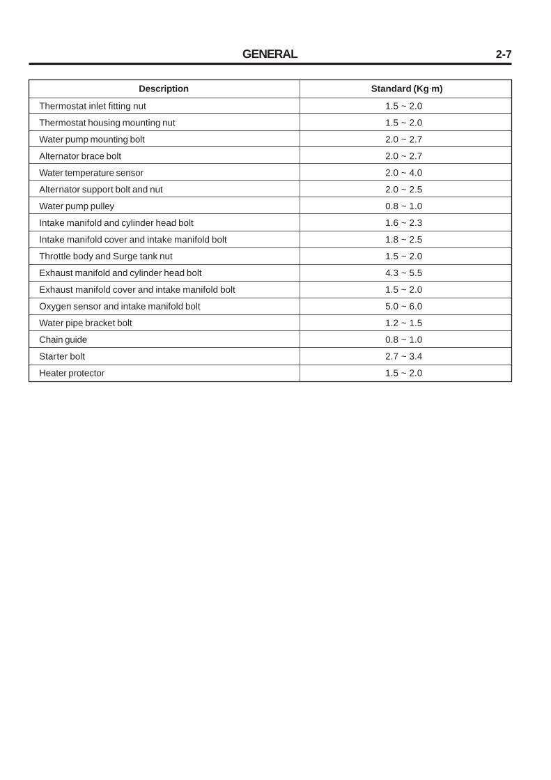
GENERAL 2-7
Thermostat inlet fitting nut
Thermostat housing mounting nut
Water pump mounting bolt
Alternator brace bolt
Water temperature sensor
Alternator support bolt and nut
Water pump pulley
Intake manifold and cylinder head bolt
Intake manifold cover and intake manifold bolt
Throttle body and Surge tank nut
Exhaust manifold and cylinder head bolt
Exhaust manifold cover and intake manifold bolt
Oxygen sensor and intake manifold bolt
Water pipe bracket bolt
Chain guide
Starter bolt
Heater protector
Description Standard (Kg·m)
1.5 ~ 2.0
1.5 ~ 2.0
2.0 ~ 2.7
2.0 ~ 2.7
2.0 ~ 4.0
2.0 ~ 2.5
0.8 ~ 1.0
1.6 ~ 2.3
1.8 ~ 2.5
1.5 ~ 2.0
4.3 ~ 5.5
1.5 ~ 2.0
5.0 ~ 6.0
1.2 ~ 1.5
0.8 ~ 1.0
2.7 ~ 3.4
1.5 ~ 2.0

GENERAL2-8
SPECIAL TOOLS
Crankshaft front oil seal installer(09214-32000)
Crankshaft front oil seal guide(09214-32100)
Camshaft oil seal installer(09221-21000)
Valve guide installer(09221-22000(A/B))
Valve stem oil seal installer(09222-22001)
Installation of the front oil seal
Installation of the front oil seal
Installation of the camshaft oil seal
Removal and installation of the valveguide
Installation of the valve stem oil seal
UseIllustrationTool (number and name)
L4GC007A
L4GC010A
L4GC006A
L4GC011A
(A)
(B)
L4GC013A

GENERAL 2-9
Valve spring compressor holder andadaptor(09222-28000, 09222-28100)
Camshaft rear oil seal installer(09231-21000)
Removal and installation of the intake orexhaust valve
1. Installation of the engine rear oil seal2. Installation of the crankshaft rear oil seal
UseIllustrationTool (number and name)
L4GC014A
L4GC016A

GENERAL2-10
Symptom Remedy
TROUBLESHOOTING
Low compression Cylinder head gasket damaged
Worn or damaged piston ring
Worn piston or cylinder
Worn or damaged valve seat
Insufficient engine oil
Oil pressure switch defective
Oil filter clogged
Worn oil pump gear or cover
Thin or diluted engine oil
Oil relief valve clogged(Open)
Excessive bearing clearance
Oil relief valve clogged(Closed)
Thin or diluted engine oil
Faulty HLA
Worn belt stem or valve guide
Insufficient engine oil
Low oil pressure
Thin or diluted engine oil
Excessive bearing clearance
Incorrect belt tension
Coolant leak from
Heater or radiator hose
Defective radiator cap
Thermostat housing
Radiator
Water pump
Foreign material into coolant
Thermostat defective
Radiator cap defective
Abnormal flow in cooling system
Loose or missing driving belt
Loose water pump
Water temperature wiring defective
Cooling pan defective
Radiator or thermostat switch defective
Inefficient coolant
Replace gasket
Replace ring
Repair or replace piston and cylinder block
Repair or replace valve and seat ring
Check engine oil level
Replace oil pressure switch
Install new filter
Replace
Replace engine oil
Replace or inspect
Replace bearing
Repair relief valve
Replace engine oil
Replace HLA
Replace belt stem or valve guide
Check engine oil level
Refer to Low oil pressure
Replace engine oil
Replace bearing
Inspect belt tension and Replace tensioner
Repair or replace parts
Retighten clamp or replace
Replace gasket or housing
Replace
Replace parts
Replace coolant
Replace parts
Replace parts
Clean or replace parts
Correct or replace
Replace
Repair or replace
Repair or replace
Replace
Add coolant
Possible cause
Low oil pressure
High oil pressure
Noisy valve
Noisy connecting rod ormainbearing
Noisy timing belt
Low coolant level
Radiator clogged
Abnormally high cool-ant temperature

GENERAL 2-11
Abnormally low cool-ant temperature
Thermostat defective
Water wiring defective
Loose connecting part
Cracked or damaged hose, pipe, and oil cooler
Loose connecting part
Pipe or muffler damaged
Breakaway exhaust plate in muffler
Rubber hanger damaged
Pipe or muffler with body Interfered
Pipe or muffler damaged
Catalytic converter damaged
Each connecting gasket damaged
Replace
Repair or replace
Retighten
Replace
Retighten
Repair or replace
Replace
Replace
Repair
Repair or replace
Replace
Replace
Oil cooling systemleak
Exhaust gas leak
Abnormal noise
Symptom RemedyPossible cause

GENERAL2-12
L4GC019A
2. If the oil level is below L mark, add about 1L of oil.
3. Check contamination and viscosity of the engine oil andreplace it if necessary.
SERVICE AND ADJUSTING PROCE-DURECHECKING ENGINE OIL
1. Be sure that the oil is between F and L marks of thedipstick.
CHECKING COMPRESSED PRESSURE
1. Prior to inspection, check that the engine oil, starter motorand battery are normal.
2. Start the engine and run it until the engine coolant tempera-ture reaches 80 ~ 95°C).
3. Stop the engine and disconnect the ignition coil and aircleaner element.
4. Remove the spark plug.
5. After opening the throttle valve completely, crank the en-gine to remove foreign material from the cylinder.
CAUTION• At this time, necessarily screen the spark plug
hole with a rag. Because hot coolant, oil, fuel,and other foreign material, being penetrated inthe cylinder through cracks can come into thespark hole during checking compressedpressure.
• When cranking the engine to test compressedpressure, necessarily open the throttle valve be-fore cranking.
6. Install the compression gauge to the spark plug hole.
Good
GENERAL 2-13
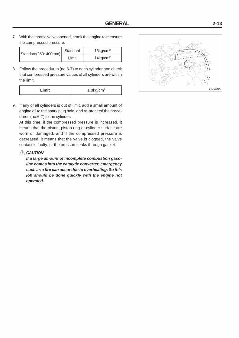
7. With the throttle valve opened, crank the engine to measurethe compressed pressure.
L4GC020ALimit 1.0kg/cm2
9. If any of all cylinders is out of limit, add a small amount ofengine oil to the spark plug hole, and re-proceed the proce-dures (no.6-7) to the cylinder.At this time, if the compressed pressure is increased, itmeans that the piston, piston ring or cylinder surface areworn or damaged, and if the compressed pressure isdecreased, it means that the valve is clogged, the valvecontact is faulty, or the pressure leaks through gasket.
CAUTIONIf a large amount of incomplete combustion gaso-line comes into the catalytic converter, emergencysuch as a fire can occur due to overheating. So thisjob should be done quickly with the engine notoperated.
8. Follow the procedures (no.6-7) to each cylinder and checkthat compressed pressure values of all cylinders are withinthe limit.
15kg/cm2
14kg/cm2Standard(250~400rpm)
Standard
Limit

GENERAL2-14
ADJUSTING TIMING BELT TENSION
Adjust the tension as the following order.
1. Remove the pan drive bracket.
2. Loosen the timing belt upper cover bolt(B) and disconnectthe upper cover(A).
3. As the illustration, insert the hex wrench to the adjustergroove and turn it counterclockwise to move the arm indi-cator in the middle of the base groove.
CAUTIONIf it is turned in reverse direction, be sure that thetensioner may function abnormally.
4. Tighten the tensioner fixing bolt with the arm indicator fixed.
LCAC021A
L4GC023A
AB
LCAC021A
AB
5. Rotate the crankshaft 2 turns clockwise and make sure theauto tensioner arm indicator is placed in the middle of thebase groove.
6. If the arm indicator is out of the middle, loosen the bolt andrepeat the previous procedure.
7. Install the timing belt upper cover(A) and tighten the bolt(B).
Tightening torque 2.3~2.9kgf·m
Tightening torque 0.8~1.0kg·m

GENERAL 2-15
TROUBLESHOOTING
1. Checking coolant leaks
1) After the coolant temperature drops below 38°C loosenthe radiator cap.
2) Check that the coolant level reaches filler neck.
3) Install the radiator cap tester to the radiator filler neckand apply a pressure of 1.4kg/cm2 .While maintaining it for 2 minutes, check the radiator,hose, and connecting part for leak.
CAUTION• Because the coolant in the radiator is too hot,
never open the cap when it hot, or injury mayoccur due to an outburst of hot water.
• Dry out the inspection part.• When removing the tester, take care not to
spill the coolant.• When removing/installing the tester as well
as testing, take care not to deform the fillerneck.
4) Replace parts if leak is detected.
2. Density test
1) Measure density of the coolant using a hydrometer.
2) After measuring the coolant temperature, calculate den-sity using the following table of temperature and density.
Temperature and density of coolant (Temp.:°C)
-16
-20
-25
-30
-36
-42
-50
3. Temperature and density of coolant
10
1.054
1.063
1.071
1.079
1.087
1.095
1.103
20
1.050
1.058
1.067
1.074
1.082
1.090
1.098
30
1.046
1.054
1.062
1.069
1.076
1.084
1.092
40
1.042
1.049
1.057
1.064
1.070
1.077
1.084
50
1.036
1.044
1.052
1.058
1.064
1.070
1.076
-16
-20
-25
-30
-36
-42
-50
30%
35%
40%
45%
50%
55%
60%
Freezing point(°C)Normal operatingtemperature(°C)
Coolanttemperature

GENERAL2-16
Recommended antifreeze Ethylene glycol
CAUTION• If the coolant contains less than 30% of
antifreeze, anticorrosion is decreased.• If the coolant contains more than 60% of
antifreeze, the engine will be fatally affected,resulting from decreased anti-freezing andengine cooling.
Use only the recommended antifreeze and donot mix with other production.
4. Recommended antifreeze
CHECKING AND ADJUSTING DRIVE BELTTENSION
1. Checking tension
1) Press the middle of the water pump pulley and alterna-tor pulley with 10Kg·f.
2) Inspect the belt deflection by pressing it.
3) If the belt deflection is out of the standard, adjust it asfollows.
ItemStandard
4.0~4.4mm
New belt Used belt5.1~5.7mmDrive belt deflection (L)

GENERAL 2-17
L4GC025A
Tension(T)Standard
New belt Used belt
2. Using a tension gauge
1) TypeBORROUGHS BT - 33 - 73FNIPPONDENSO BTG - 2
2) How to useInsert the belt between the gauge hook and spindleand press the tension gauge handle.Leave the handle and read the gauge.
CAUTION• The belt used over 5 minutes should be ad-
justed as used belt of standard.• Check that the belt is installed correctly.• When the belt is loosened, slip noise is heard.
L4GC026A
ADJUSTING
1. Loosen the alternator support bolt A nut and adjustinglock bolt B .
2. Adjust the belt tension by moving the alternator brace ad-justing bolt to T direction.
Alternator adjusting lock bolt B
Alternator support bolt A
1.2~1.5kg·m
2~2.5kg·mL4GC027A
65~75kg 40~50kg
BORROUGHS type
SpindleHook
Hook
Spindle
Dial
V-ribbed belt
L4GC024A
NIPPONDENSO type
RESET button
V-ribbed belt
HookSpindle
RESET point
Pulley
Bad BadGood
B
A
T
Water pump pulley

GENERAL2-18
L4GC028A
3. Tighten the bolt A and then tighten B to the specifiedtorque.
CAUTION • If the belt tension is too excessive, noise as well
as early wear of belt occurs and the water pumpbearing and alternator bearing are damaged.
• If the belt is too loose, due to early wear of beltand insufficient power of alternator, battery andwater pump become inefficient and finally en-gine is overheated or damaged.
CHECKING BELT FOR DAMAGE
Check the following items and replace the belt if defective.
1. Check the belt surface for damage, wear and crack.
2. Check the belt surface for oil or grease contamination.
3. Check the rubber part for wear or hardening.
4. Check the pulley surface for crack or damage.
Cambus
Ribbed rubber
Adhesive rubber
Inner wire

CYLINDER BLOCK 2-19
CYLINDER BLOCK
COMPONENTS
L4GC029ATightening torque: kg·m
REMOVAL
1. Flywheel2. Timing belt3. Cylinder head4. Oil level gauge5. Oil pressure switch6. Water pump7. Oil pan8. Oil screen9. Piston, Connecting rod10. Front case
11. Rear oil seal
12. Crankshaft
L4GC030A
Adaptor
T:1.3~1.5Oil pressure switch

CYLINDER BLOCK2-20
INSPECTION
CYLINDER BLOCK
1. Inspect the cylinder block for scratch, fur and rust visually,check for invisible crack or other deformation using a propertool and repair or replace if necessary.
2. Measure flatness of the cylinder block upper surface usinga straight edge and a thickness gauge. When measuring,the cylinder block upper surface should be flat without afragment.
3. Measure the cylinder bore towards A and B directions at 3-point height using a cylinder gauge. If the cylinder bore islarger than standard and the cylinder wall is scratched orfurred excessively, bore and hone the cylinder block andinstall a new oversize piston and ring.
L4GC031A
Flatness
Parallelism
0.03mm or less
0.15mm or less
Cylinder I.D
Cylinder I.D cylindricity
82.00 ~ 82.03mm
0.01mm
Clearance between piston and cylinder 0.02 ~ 0.04mm
Items
0.25 OS
0.50 OS
0.75 OS
1.00 OS
Size
0.25mm
0.50mm
0.75mm
1.00mm
4. If the top ridge is partially worn, cut it with a ridge reamer.
5. There are 4 kinds of oversize piston.
6. To bore the cylinder bore to the oversize, maintain the clear-ance between oversize piston and bore and use the samesize of pistons. When measuring the piston O.D, measureflatness of the skirt thrust surface at 47mm below from thepiston top land.

CYLINDER BLOCK 2-21
INSTALLATION
Installation is the reverse order of removal.
LUBRICATION SYSTEM2-22
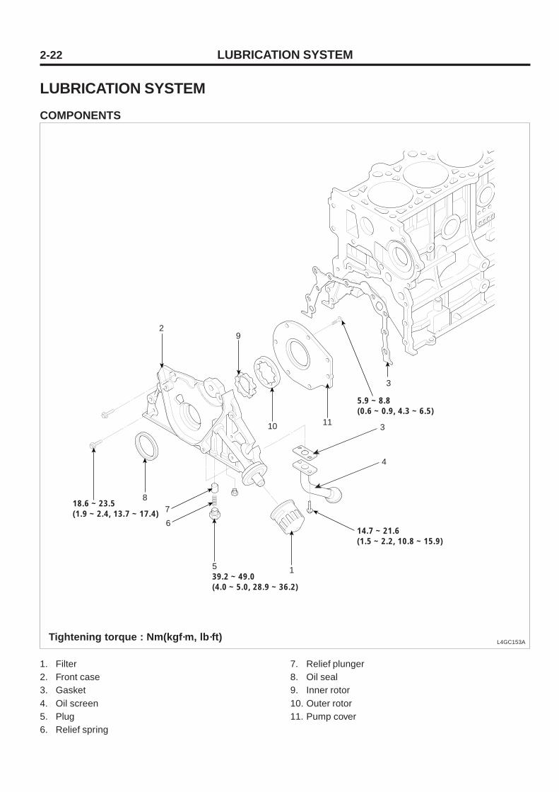
LUBRICATION SYSTEMCOMPONENTS
L4GC153ATightening torque : Nm(kgf·m, lb·ft)
1. Filter2. Front case3. Gasket4. Oil screen5. Plug6. Relief spring
7. Relief plunger8. Oil seal9. Inner rotor10. Outer rotor11. Pump cover
1539.2 ~ 49.0(4.0 ~ 5.0, 28.9 ~ 36.2)
18.6 ~ 23.5(1.9 ~ 2.4, 13.7 ~ 17.4)
5.9 ~ 8.8(0.6 ~ 0.9, 4.3 ~ 6.5)
14.7 ~ 21.6(1.5 ~ 2.2, 10.8 ~ 15.9)
4
3
6
78
29
10 11
3

LUBRICATION SYSTEM 2-23
REMOVAL
1. Drain engine oil.
2. Remove the drive belts.
3. Turn the crankshaft and align the white groove on the crank-shaft pulley with the pointer on the lower cover.
4. Remove the timing belt.
5. Remove the oil pan and oil screen.
6. Remove the front case.
LCAC148A
LCAC150A
BC
D
A
AB
A B
LCAC149A
1) Remove the screws (B) from the pump housing, thenseparate the housing and cover (A).
2) Remove the inner (A) and outer (B) rotos.

LUBRICATION SYSTEM2-24
REPLACE OIL AND FILTER
CAUTION• Prolonged and repeated contact with mineral
oil will result in the removal of natural fats fromthe skin, leading to dryness, irritation anddermatitis. In addition, used engine oil containspotentially harmful contaminants which maycause skin cancer.
• Exercise caution in order to minimize the lengthand frequency of contact of your skin to usedoil.
• In order to preserve the environment, used oiland used oil filter must be disposed of only atdesignated disposal sites.
1. Drain engine oil.1) Remove the oil filter cap.2) Remove the oil drain plug, and drain the oil into a con-
tainer.
2. Replace oil filter.1) Remove the oil filter.2) Check and clean the oil filter installation surface.3) Check the part number of the new oil filter is as same
as old one.4) Apply clean engine oil to the gasket of a new oil filter.5) Lightly screw the oil filter into place, and tighten it until
the gasket contacts the seat.6) Tighten it an additional 3/4 turn.
3. Refill with engine oil filter.1) Clean and install the oil drain plug with a new gasket.
Torque39.2~44.1N.m
(4.0~4.5kgf.m, 28.9~32.5lb-ft)
2) Fill with fresh engine oil.
Capacity Drain and refill
Oil filter
4.0L(4.23US qts, 3.52Lmp qts)
0.3L(0.32US qts, 0.26Lmp qts)
3) Install the oil filter cap.
4. Start engine and check for oil leaks.
5. Recheck engine oil level.

LUBRICATION SYSTEM 2-25
Tightening torque5.9~8.8N.m
(0.6~0.9kgf.m, 4.3~6.5lb-ft)
INSPECTION
1. Install oil pump.1) Place the inner and outer rotors into front case with the
marks facing the oil pump cover side.2) Install the oil pump cover(A) to front case with the 7
screws(B).
A B
LCAC149A
LCAC148A
BC
D
A
2. Check that the oil pump turns freely.
3. Install the oil pump on the cylinder block.Place a new front case gasket on the cylinder block. Applyengine oil to the lip of the oil pump seal. Then, install the oilpump onto the crankshaft. When the pump is in place, cleanany excess grease off the crankshaft and check that the oilseal lip is not distorted.
A
B
C
D
25mm(0.98in)
20mm(0.787in)
38mm(1.496in)
45mm(7.771in)
Body length
Tightening torque
LCAC151A09214-32000
4. Apply a light coat of oil to seal lip.
5. Using the SST(09214-32000), install the oil seal.
19.6~26.5N.m(2.0~2.7kgf.m, 14.5~19.5lb-ft)
LUBRICATION SYSTEM2-26
6. Install the oil screen.
7. Install the oil pan.
NOTEClean the oil pan gasket mating surfaces.
LCAC152A
A
B
C
LCAC036A
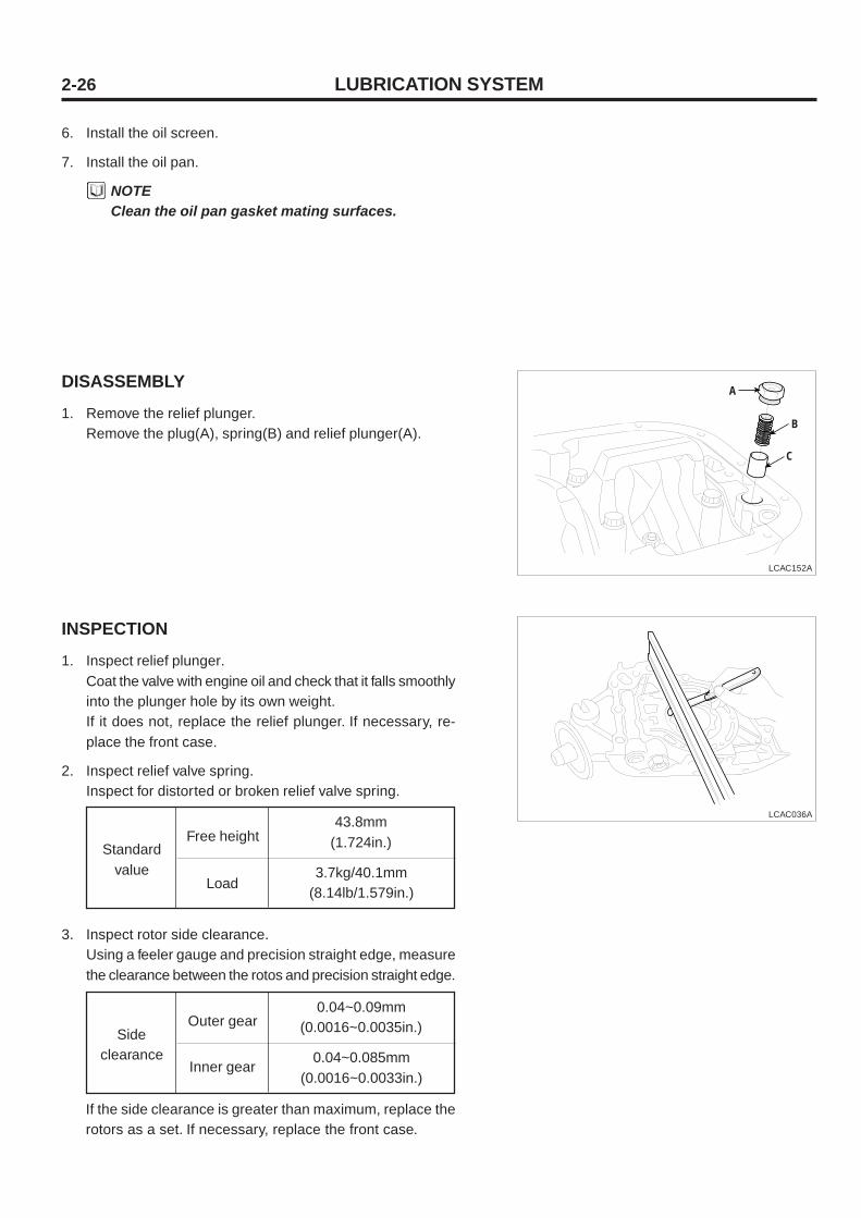
DISASSEMBLY
1. Remove the relief plunger.Remove the plug(A), spring(B) and relief plunger(A).
INSPECTION
1. Inspect relief plunger.Coat the valve with engine oil and check that it falls smoothlyinto the plunger hole by its own weight.If it does not, replace the relief plunger. If necessary, re-place the front case.
2. Inspect relief valve spring.Inspect for distorted or broken relief valve spring.
Free height43.8mm
(1.724in.)Standardvalue
3. Inspect rotor side clearance.Using a feeler gauge and precision straight edge, measurethe clearance between the rotos and precision straight edge.
Load3.7kg/40.1mm
(8.14lb/1.579in.)
Outer gear0.04~0.09mm
(0.0016~0.0035in.)Sideclearance
Inner gear0.04~0.085mm
(0.0016~0.0033in.)
If the side clearance is greater than maximum, replace therotors as a set. If necessary, replace the front case.
LUBRICATION SYSTEM 2-27
LCAC034A
LCAC035A
LCAC152A
A
B
C
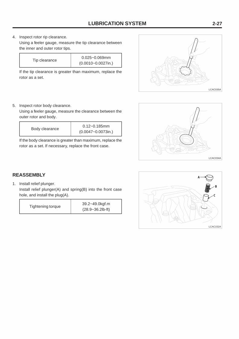
4. Inspect rotor rip clearance.Using a feeler gauge, measure the tip clearance betweenthe inner and outer rotor tips.
Tip clearance0.025~0.069mm
(0.0010~0.0027in.)
If the tip clearance is greater than maximum, replace therotor as a set.
5. Inspect rotor body clearance.Using a feeler gauge, measure the clearance between theouter rotor and body.
Body clearance0.12~0.185mm
(0.0047~0.0073in.)
If the body clearance is greater than maximum, replace therotor as a set. If necessary, replace the front case.
REASSEMBLY
1. Install relief plunger.Install relief plunger(A) and spring(B) into the front casehole, and install the plug(A).
Tightening torque39.2~49.0kgf.m(28.9~36.2lb-ft)

MAIN MOVING SYSTEM2-28
MAIN MOVING SYSTEM
CAMSHAFT, HLA, TIMING CHAIN
COMPONENTS
L4GC043A
Tightening torque : kg·m
HLA
T : 0.8~1.0
T : 0.8~1.0
Center cover
Cylinder head cover
Gasket
Bearing cap(rear)
Chain guide
Exhaust camshaft
Intake camshaft
Camshaft oil seal
Bearing cap(front)
Camshaft sprocket
T : 10~12
T : 0.25~0.35

MAIN MOVING SYSTEM 2-29
REMOVAL
1. Remove the breeder hose and P.C.V hose.
2. Remove the center cover.
3. Remove the ignition coil.
4. Remove the timing belt upper cover.
5. Remove the cylinder head cover.
L4GC046A
6. Remove the tensioner.
7. Loosen the camshaft sprocket bolt and remove the cam-shaft sprocket.
8. Loosen the bearing cap bolt and after removing the bear-ing cap, remove the camshaft.
9. Remove the timing chain.
10. Remove the HLA.
L4GC045A
L4GC044A

MAIN MOVING SYSTEM2-30
INSPECTION
CAMSHAFT
1. Check the camshaft journal for wear and if the journal isseriously worn, replace the camshaft.
2. Check the cam lobe for damage and if the lobe is severelydamaged or worn, replace the camshaft.
3. Check the cam surface for abnormal wear and damageand replace it if necessary.
4. Check the cylinder head camshaft journal for damage andif the surface is severely damaged, replace the cylinderhead assembly.
5. Lightly put the camshaft on the cylinder head as shown inthe illustration and after installing a dial gauge towards shaft,check the endplay.
L4GC047A
Camshaft endplay 0.1 ~ 0.2mm
Limit
42.9
42.9
Items
Cam height
Standard
43
43
Intake
Exhaust
OIL SEAL
1. Check the oil seal surface for wear and if the seal lip por-tion is worn, replace it.
2. Check the camshaft oil seal lip contact surface for partialwear and replace it if necessary.
L4GC048A
HLA(Hydraulic Lash Adjuster)
1. HLA I.D : 33(-0.025/-0.041)
2. How to remove noise when it heard from valve1) Prior to engine warm-up, check that the engine oil
level is normal.2) Warm-up the engine.3) If the valve noise is heard at engine warm-up, air-
bleed the system.4) How to air-bleed
a) During remaining it for 10 minutes at 3,000 rpmand over 5 minutes at idle, check that the valvenoise is heard.
b) Repeat the above step(a) only once or twice.
L4GC157A

MAIN MOVING SYSTEM 2-31
5) If the valve noise is still heard after following the abovestep 4), replace the hydraulic lash adjuster(HLA) whichmakes noise.
6) If the valve noise is heard after replacing parts, necessarily repeat the above step 4).
7) After air-bleeding the system and replacing parts toremove noise, if the valve noise is re-heard 2-3 daysafter, it might be affected from defective HLA, so replace the defective HLA.
NOTEIn case of the vehicle with HLA, when initiallystarting the engine, it is normal if valve noise ismomentarily heard.
CAUTION1) Because HAL is precision parts, take care
not to come foreign materials such as a dustfrom outside.
2) Do not disassemble HLA.3) When cleaning HLA, use clean diesel oil.4) Take care not to make scratches and sharp
edges to O.D of HLA.5) With HLA filled with engine oil, grasp A and
press B by hand as shown in the illustration,if the HLA is moving, replace the HLA.
TIMING CHAIN
1. Check the timing chain bushing and plate portion for wearand if those are severely worn, replace those.
L4GC022A
A
B
L4GC061A
Mounting mark
INSTALLATION
1. Install HLA
2. After Installing the intake and exhaust camshaft by aligning it with the timing mark on the timing chain sprocket, installthe camshaft to the cylinder head.
CAUTION• Apply engine oil to the camshaft journal and
cam.• There a detective pin for TDC sensor in the in-
take camshaft rear end and a dowel pin in theintake camshaft front end.
L4GC064A
Exhaust timing chain sprocketTiming chain
Timing markExhaust timing chain sprocket

MAIN MOVING SYSTEM2-32
L4GC065A
3. Install the camshaft cap.Check the intake and exhaust identification marks.(Checkcap number and arrow and take care not to change thebearing cap position and direction.)I: Intake camshaftE: Exhaust camshaft
Cap numberIntake, exhaust mark
L4GC067A
L4GC068A
L4GC069A
4. Tighten the bearing cap to the specified torque by tighten-ing bolts 2-3 times as shown in the illustration.
Bearing cap bolt 1.4 ~ 1.5kg·m
5. Using the special tool camshaft oil seal installer andguide , press the camshaft oil seal. Necessarily apply en-gine oil to the oil seal lip. Insert the oil seal through thecamshaft front end and install it by tapping on the installerwith a hammer until the oil seal reaches 8.5mm from thecamshaft front end.
6. Install the camshaft sprocket to the specified torque.
Camshaft sprocket bolt 10 ~ 12kg·m
CAUTIONAlign the timing marks on the camshaft sprocketand the crankshaft sprocket. At this time piston no.1 cylinder should be placed on the compressiondead point.
09221-21000
I1 I2 I3 I4
E1
E1 E1
E1
Camshaft sprocket side
I5E
5

MAIN MOVING SYSTEM 2-33
L4GC053A
7. Place the cylinder no.1 to the dead point.1) Rotate the crankshaft pulley so as to align it with T
mark on the timing belt low cover.
2) Check that the camshaft timing pulley hole is alignedwith timing mark on the bearing cap.If it is not aligned, readjust it by rotate the crankshaft to360° .
L4GC154A
8. Assembly the timing belt.

MAIN MOVING SYSTEM2-34
L4GC045A
9. Install the cylinder head cover. Apply sealant as shown inthe illustration.
Cylinder head cover 0.8 ~ 1.0kg·m
Apply engine oil to the oil seal lip to help install the cylinderhead cover oil seal to the spark plug pipe smoothly.
CAUTION• Necessarily tighten the cylinder head cover bolt
to the specified torque.If it is tightened too much, the head cover canbe deformed resulting in oil leaks and the headcover bolt can be broken resulting in cylinderhead replacement.
• When installing after head cover removing, nec-essarily apply sealant to the head cover rear andfront portion.
• Because the head cover is made of plastic, takecare not to drop tools on the head cover upperportion when removing/installing the engineparts.
• When installing after head cover removing, af-ter checking the head gasket for damage, re-use it if it is normal.
• When applying/draining engine oil, take care notto spill oil on the head cover upper surface, ifoil is spilled, wipe it out completely with a pa-per and a rag.
10. Install the timing belt cover.
11. Assembly the ignition coil.
12. Install the spark plug center cover.
Timing belt cover 0.8 ~ 1.0kg·m
Center cover 0.25 ~ 0.35kg·m

MAIN MOVING SYSTEM 2-35
L4GC060A
"F"
"G"
Eng
ine
oil #
40 o
r eq
uiva
lent
SE
CT
ION
"B
-B"
"B"
"B"
"A"
"A"
"D"
"E"
Sea
lant
Hea
d co
ver
VIE
W "
G"
Sea
lant
3 V
IEW
"D
", "
E",
"F
"
Cyl
inde
r he
ad
VIE
W "
D",
"E
", "
F"

MAIN MOVING SYSTEM2-36
CRANKSHAFT
COMPONENTS
L4GC072A
Tightening torque : kg·m
Thrust bearing
Crankshaft center bearing
Crankshaft upper bearing
Crankshaft lower bearing
T : 2.7~3.3+(60 ~ 65 )
T : 1.1~1.2
Main bearing cap
Crankshaft center bearing
Crankshaft
Crankshaft position sensor wheel

MAIN MOVING SYSTEM 2-37
DISASSEMBLY
1. Remove the timing belt train, front case, flywheel, cylinderhead assembly, and oil pan.
2. Remove the rear oil seal.
3. Disconnect the connecting rod cap.
4. Remove the main bearing cap. (Arrange it in order)
5. Remove the crankshaft.
6. Disassemble the crankshaft position sensor wheel.
NOTEPut an identification mark on the main bearing capto refer to the original position and direction.
INSPECTION
1. Crankshaft
1) Check the oil hoe for clogging as well as crankshaftjournal pin for damage, uneven wear and crack. Repairor replace parts if necessary.
2) Inspect out of circularity of the crankshaft journaltaper and pin.
2. Main bearing and connecting rod bearingVisually inspect each bearing for scratch, melting, sticking,and fault contact and replace the bearing if necessary.
Crankshaft journal O.D
Crank pin O.D
57mm
45mm
0.01mm or lessOut of circularity of crankshaft journal
pin

MAIN MOVING SYSTEM2-38
ASSEMBLY
1. After checking the sensor wheel for damage and crack,replace it if necessary.
2. Inspect the clearance between the sensor wheel and crankposition sensor.
L4GC073A
3. Measuring oil clearance
1) Measure O.D of the crankshaft journal and pin.2) Measure diameter of the crankshaft bore and connect-
ing rod bore.3) Measure the thickness of the crankshaft and connect-
ing rod bearing.4) Calculate clearance by subtracting O.D of the journal
pin and thickness of the bearing from diameter of thebore.
Journal oil clearance
Pin oil clearance
0.028 ~ 0.048mm
0.024 ~ 0.044mm
Main bearing cap bolt
Connecting rod cap bolt
2.7 ~ 3.3kg·m+(60° ~ 65° )
5.0 ~ 5.3kg·m
4. Oil sealCheck the front and rear oil seal and replace it with newparts if necessary.
Clearance between sensor wheel andcrank position sensor
0.5 ~ 1.1mm
If the clearance is out of specified values, check the sensorwheel for balancing and the crank position sensor for in-stallation and replace those if necessary.
CAUTIONSensor wheel as one of the electronic control af-fects performance if deformed or damaged, so becareful when handling it.
3. Install the upper main bearing to the cylinder block. Whenreusing the main bearing, refer to the identification markduring assembly.
4. Install the bearing shaft and apply engine oil to the journaland pin.

MAIN MOVING SYSTEM 2-39
5. Install the bearing cap and tighten the cap bolt to the speci-fied torque from the center in order.(Tighten the bearing cap bolts to the specified torque bytightening bolts step by step 2-3 times equally)
Main bearing cap bolt
Connecting rod cap bolt
2.7 ~ 3.3kg·m+(60° ~ 65° )
5.0 ~ 5.3kg·m
When installing the cap, proper number of cap should beinstalled as well as arrow mark should be directed to theengine crank pulley. L4GC074A
L4GC075A
L4GC076A
6. Check that the crankshaft for free rotation and proper clear-ance between the center main bearing thrust flange andconnecting rod big-end bearing.
7. Using the special tool Crankshaft oil seal installer (09231-21000) , fully insert the oil seal into the crankshaft rear oilseal case.
Crankshaft end-play 0.06 ~ 0.260mm
8. Install the rear oil seal case and gasket and tighten 5 bolts.When installing, apply engine oil to the oil seal round andcrankshaft.
9. Install the flywheel, front case, oil pan, and timing belt train.
09231 - 21000
MAIN MOVING SYSTEM2-40
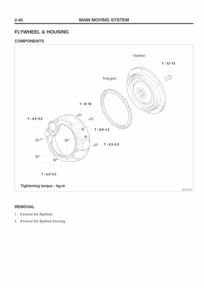
FLYWHEEL & HOUSING
COMPONENTS
L4GC077A
Tightening torque : kg·m
REMOVAL
1. Remove the flywheel.
2. Remove the flywheel housing.
Ring gear
T : 12~13
Flywheel
T : 4.3~5.5
T : 4.3~5.5
T : 4.3~5.5
T : 8~10
T : 0.8~1.2

MAIN MOVING SYSTEM 2-41
INSPECTION1. Check the ring gear for damage and crack and replace it if
necessary.
ASSEMBLY
1. Install the flywheel housing and tighten the bolt to the speci-fied torque.
2. Install the flywheel assembly and tighten the bolt to thespecified torque.
Flywheel bolt 12 ~ 13kg·m

MAIN MOVING SYSTEM2-42
PISTON AND CONNECTING ROD
COMPONENTS
L4GC078A
Tightening torque : kg·m
T : 5.0 ~ 5.3
No.1 piston ring
No.2 piston ring
Piston pin
Connecting rod
Upper bearing
Lower bearing
Connecting rod bearing cap
Connecting rod bearing
Bolt
Piston

MAIN MOVING SYSTEM 2-43
DISASSEMBLY
1. Remove the cylinder head assembly.
NOTEPut an identification mark on the connecting rodand cap before disassembly to refer to the originalposition and direction.
2. Remove the oil pan and remove the oil screen.
3. After removing the connecting rod cap, remove the pistonand connecting rod assembly from the cylinder. Arrangethe connecting rod bearing in cylinder number order.
4. Using the special tool piston pin setting tool (09234-33001) , disassemble the piston from the connecting rodas below.
1) Remove the piston ring.2) When placing the assembly on a press, face the front
mark on the piston upward.3) Using the press, remove the piston pin.
L4GC079A
INSPECTION
PISTON AND PISTON PIN
1. Check the piston for scratch, wear, etc. and replace it ifnecessary.
2. Check the piston ring for break, damage and abnormal wearand replace it if necessary. When replacing the piston, thering should be replaced also.
3. Check that the piston pin is inserted in the piston hole andreplace the piston and pin if necessary.Piston should be smoothly pressed at normal roomtemperature.
PISTON RING
1. When measuring the side clearance of piston ring, if themeasured value is out of the limit, insert a new ring to thering groove and re-measure the side clearance.
No.1
No. 2
Item Limit
0.1mm
0.1mm
Specified value
0.04 ~ 0.08mm
0.03 ~ 0.07mm
Side clearanceof piston ring
09234-33001
Press ram
Installer
Support
Remover
Connecting rod Adaptor
Piston
MAIN MOVING SYSTEM2-44
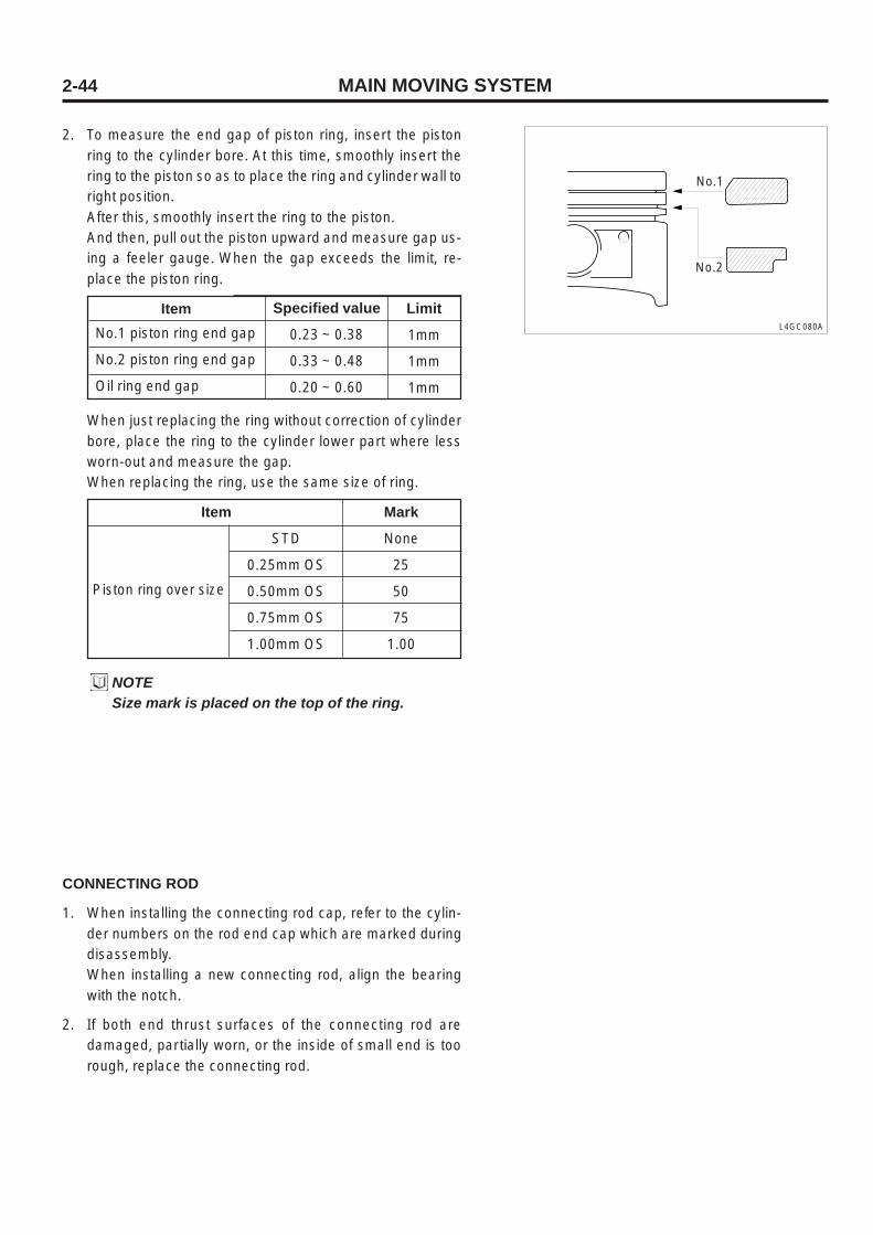
2. To measure the end gap of piston ring, insert the pistonring to the cylinder bore. At this time, smoothly insert thering to the piston so as to place the ring and cylinder wall toright position.After this, smoothly insert the ring to the piston.And then, pull out the piston upward and measure gap us-ing a feeler gauge. When the gap exceeds the limit, re-place the piston ring.
ItemNo.1 piston ring end gap
No.2 piston ring end gap
Oil ring end gap
Limit
1mm
1mm
1mm
Specified value
0.23 ~ 0.38
0.33 ~ 0.48
0.20 ~ 0.60
When just replacing the ring without correction of cylinderbore, place the ring to the cylinder lower part where lessworn-out and measure the gap.When replacing the ring, use the same size of ring.
Piston ring over size
Mark
None
25
50
75
1.00
STD
0.25mm OS
0.50mm OS
0.75mm OS
1.00mm OS
Item
NOTESize mark is placed on the top of the ring.
L4GC080A
CONNECTING ROD
1. When installing the connecting rod cap, refer to the cylin-der numbers on the rod end cap which are marked duringdisassembly.When installing a new connecting rod, align the bearingwith the notch.
2. If both end thrust surfaces of the connecting rod aredamaged, partially worn, or the inside of small end is toorough, replace the connecting rod.
No.1
No.2

MAIN MOVING SYSTEM 2-45
L4GC081A
Bending of connecting rod
Torsion of connecting rod
0.05mm
0.1mm
3. Using a connecting rod aligner, measure bending and tor-sion of rod and if the measured value is around the limit,correct the rod with a press.But when the rod is severely bended or damaged, neces-sarily replace it.
ASSEMBLY
1. Using the special tool piston pin setting tool (09234-33001) , assemble the piston and connecting rod as below.
1) Apply engine oil to the outer surface of the piston pinand small end bore of the connecting rod.
L4GC082A
2) With the front mark faced upward, fix the connectingrod and piston and insert it into the piston pin assembly.
3) Using a press, press-fit the piston pin into the pin holewith the specified pressure on the pin end through thepush rod.If the pressure is required more than the specified value,follow the next step.
Piston side
Connecting rod side
0 (engraved)
Number (embossed)
Front mark
Press-fit pressure of piston pin 350 ~ 1350kg
L4GC083A
Notch
09234-33001
Press ram
Installer
Support
Remover
Connecting rod Adaptor
Piston

MAIN MOVING SYSTEM2-46
4) Rotate the push rod to a half turn, remove the pistonconnecting rod assembly from the support.
5) After press fitting the piston pin, check that the con-necting rod for smooth slip and free movement.
2. Install the piston ring to the piston in the following order.
1) Install 3 pieces of oil ring. Install the spacer lower siderail and upper side rail in order.When installing the side rail, do not use a piston ringexpander to expand gap as usual because the side railis broken. After placing one end of the side rail betweenthe piston ring groove and spacer, grasp the lower sidesecurely and press the side rail to the position by handas shown in the illustration.At this time, after installing the lower side rail, installthe upper side rail.
L4GC084A
L4GC085A
CAUTION• After installing 3 pieces of oil ring, check
the upper and lower side rails for smoothrotation.
• The spacer expander gap should be awayfrom the rail gap to 45° or more.
Side rail gap
Side rail
Spacer
MAIN MOVING SYSTEM 2-47
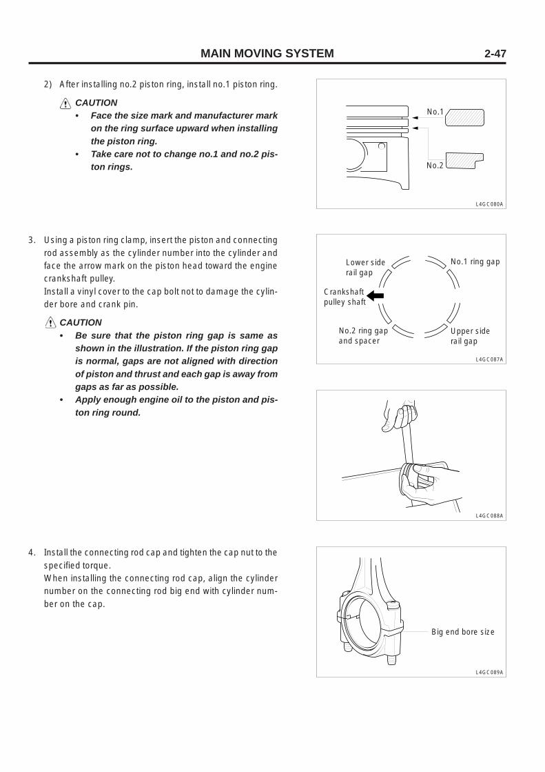
2) After installing no.2 piston ring, install no.1 piston ring.
CAUTION• Face the size mark and manufacturer mark
on the ring surface upward when installingthe piston ring.
• Take care not to change no.1 and no.2 pis-ton rings.
L4GC080A
3. Using a piston ring clamp, insert the piston and connectingrod assembly as the cylinder number into the cylinder andface the arrow mark on the piston head toward the enginecrankshaft pulley.Install a vinyl cover to the cap bolt not to damage the cylin-der bore and crank pin.
CAUTION• Be sure that the piston ring gap is same as
shown in the illustration. If the piston ring gapis normal, gaps are not aligned with directionof piston and thrust and each gap is away fromgaps as far as possible.
• Apply enough engine oil to the piston and pis-ton ring round.
L4GC087A
L4GC088A
4. Install the connecting rod cap and tighten the cap nut to thespecified torque.When installing the connecting rod cap, align the cylindernumber on the connecting rod big end with cylinder num-ber on the cap.
L4GC089A
No.1
No.2
Lower side rail gap
Crankshaft pulley shaft
No.2 ring gap and spacer
Upper side rail gap
No.1 ring gap
Big end bore size

MAIN MOVING SYSTEM2-48
L4GC090A
6. Install the oil screen.
7. Install the oil pan.
8. Install the cylinder head.
5. Inspect clearance of the connecting rod big end.
Clearance of connecting rod big end 0.1 ~ 0.25mm

COOLING SYSTEM 2-49
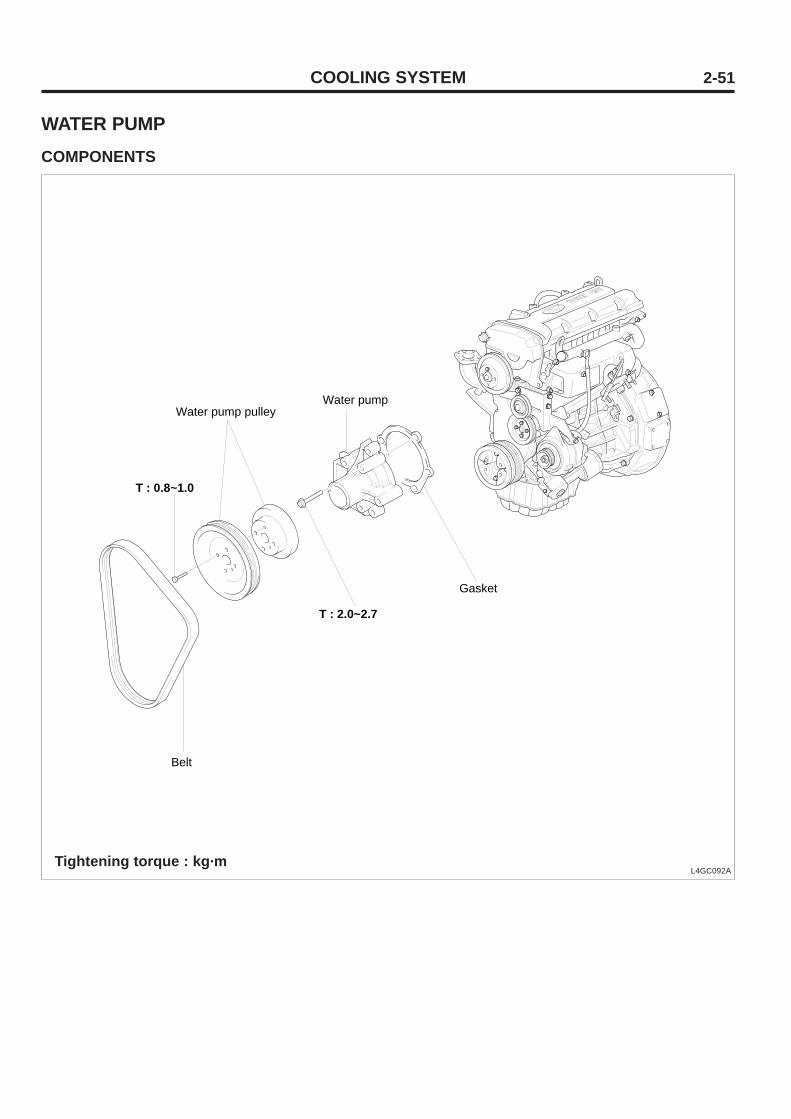
COOLING SYSTEMWATER PUMP, COOLANT PIPE AND HOSECOMPONENTS
L4GC091ATightening torque : kg·m
25614-23000 (Gasket)
25600-23C00 (Water temperature control)
11233-08557S (Washer-Bolt)T : 1.5~2.0 kg.m
13103-08007K (Nut)T : 1.5~2.0 kg.m
13602-08006B (Spring washer)
39220-38020 (Water temperature sensor & Unit)T : 2.0~4.0 kg.m
COOLING SYSTEM2-50
INSPECTION
Check the coolant pipe and hose for crack, damage, and clog-ging and replace it if necessary.
INSTALLATION
After getting water around O-ring, insert it the groove in thecoolant intake pipe end and press-fit the pipe.
CAUTION• Do not apply oil or grease to the O-ring.• Take care not to dirt the coolant pipe connect-
ing part with sand or dust.• Press-fit the coolant intake pipe completely.
COOLING SYSTEM 2-51
WATER PUMPCOMPONENTS
L4GC092ATightening torque : kg·m
Water pump
Gasket
Belt
T : 2.0~2.7
T : 0.8~1.0
Water pump pulley
COOLING SYSTEM2-52
INSPECTION
1. Check each part for crack, damage, and wear and replacethe water pump if necessary.
2. Check the bearing for damage, abnormal noise and badrotation and replace the water pump if necessary.
3. Check the seal unit from C hole for leak and replace thewater pump assembly if necessary.
INSTALLATION
1. Clean the gasket surface of the water pump body and cyl-inder block.
2. After getting water around new O-ring, install it the groovein the coolant intake pipe front end. Do not apply oil or greaseto the O-ring.
3. Install a new water pump gasket and water pump assembly.Tighten it to the specified torque.
L4GC093A
L4GC094A
A
B
2.0 ~ 2.7 kg·m
2.0 ~ 2.4 kg·m
WATERPUMP AND CYLINDER BLOCK
C
INSPECTION
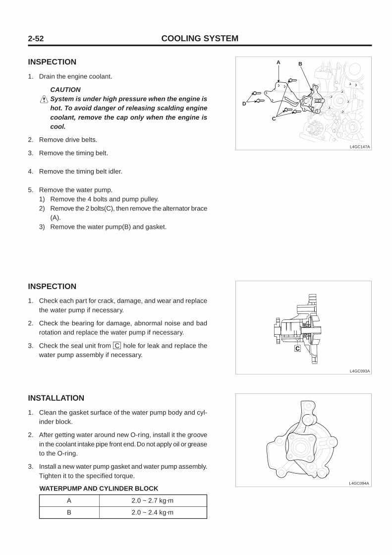
1. Drain the engine coolant.
CAUTIONSystem is under high pressure when the engine ishot. To avoid danger of releasing scalding enginecoolant, remove the cap only when the engine iscool.
2. Remove drive belts.
3. Remove the timing belt.
4. Remove the timing belt idler.
5. Remove the water pump.1) Remove the 4 bolts and pump pulley.2) Remove the 2 bolts(C), then remove the alternator brace
(A).3) Remove the water pump(B) and gasket.
L4GC147A
A B
C
D

COOLING SYSTEM 2-53
4. Install the timing belt tensioner and timing belt.Adjust the timing belt tension and install the timing belt cover.
5. After installing the water pump pulley and driving belt, ad-just the belt tension.
6. Add the standard coolant.
7 . Run the engine and check for leak.

COOLING SYSTEM2-54
L4GC096A
THERMOSTATCOMPONENTS
L4GC095ATightening torque : kg·m
INSPECTION
1. Check the valve closed at room temperature.
2. Check for defect or damage.
3. Heat the thermostat as shown in the illustration and mea-sure the valve open temperature and full open temperature.
Open
Full open
82°C
95°C
Valve open temperature
INSTALLATION
1. Check that the thermostat flange is correctly inserted tothe thermostat housing socket. At this time, upward thejiggle valve and make contact to the hole.
2. Install a new gasket and water inlet fitting.
3. Add coolant.
Gasket
Water inlet fitting
ThermostatThermostat housing
Gasket
T : 1.5 ~ 2.0
COOLING SYSTEM 2-55
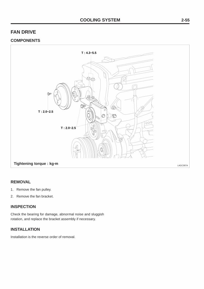
FAN DRIVECOMPONENTS
L4GC097ATightening torque : kg·m
REMOVAL
1. Remove the fan pulley.
2. Remove the fan bracket.
INSPECTION
Check the bearing for damage, abnormal noise and sluggishrotation, and replace the bracket assembly if necessary.
INSTALLATION
Installation is the reverse order of removal.
T : 2.0~2.5
T : 4.3~5.5
T : 2.0~2.5

INTAKE AND EXHAUST SYSTEM2-56
INTAKE AND EXHAUST SYSTEM
INTAKE MANIFOLD
COMPONENTS
Tightening torque : kg·mL4GC100A
T : 1.5~2.0
Intake manifold gasket
Intake manifold
Stay
PCV NipplePlug

INTAKE AND EXHAUST SYSTEM 2-57
REMOVAL
1. Disconnect the map sensor and the connector.
2. Remove the P.C.V valve hose.
3. Disconnect the fuel injector connector and the wiringharness.
4. Remove the delivery pipe with the fuel injector attached.
CAUTIONWhen removing the delivery pipe, take care not todrop the injector.
8. Remove the intake manifold stay.
9. Remove the intake manifold and gasket.
L4GC105A
INSPECTION
1. Intake manifoldCheck each component for damage and crack.
2. Air hoseCheck each component for damage and crack.

INTAKE AND EXHAUST SYSTEM2-58
INSTALLATION
1. After replacing the intake manifold gasket, install it to thecylinder head and then to the intake manifold.
2. Install the delivery pipe and injector assembly to the intakemanifold.
L4GC105A
CAUTIONCheck that the injector is interfered with the injec-tor hole in the intake manifold.
3. Install the fuel injector connector and wiring harness.
4. Connect the high-pressure fuel hose.
5. Connect the P.C.V valve hose.
6. Check connectors for connection.

INTAKE AND EXHAUST SYSTEM 2-59
EXHAUST MANIFOLD
COMPONENTS
CAUTIONDo not tighten parts excessively, observe the speci-fied torque.
L4GC103ATightening torque : kg·m
T : 5.0 ~ 6.0Oxygen sensor
T : 4.3 ~ 5.5
T : 1.5 ~ 2.0
Exhaust Manifold Gasket
INTAKE AND EXHAUST SYSTEM2-60
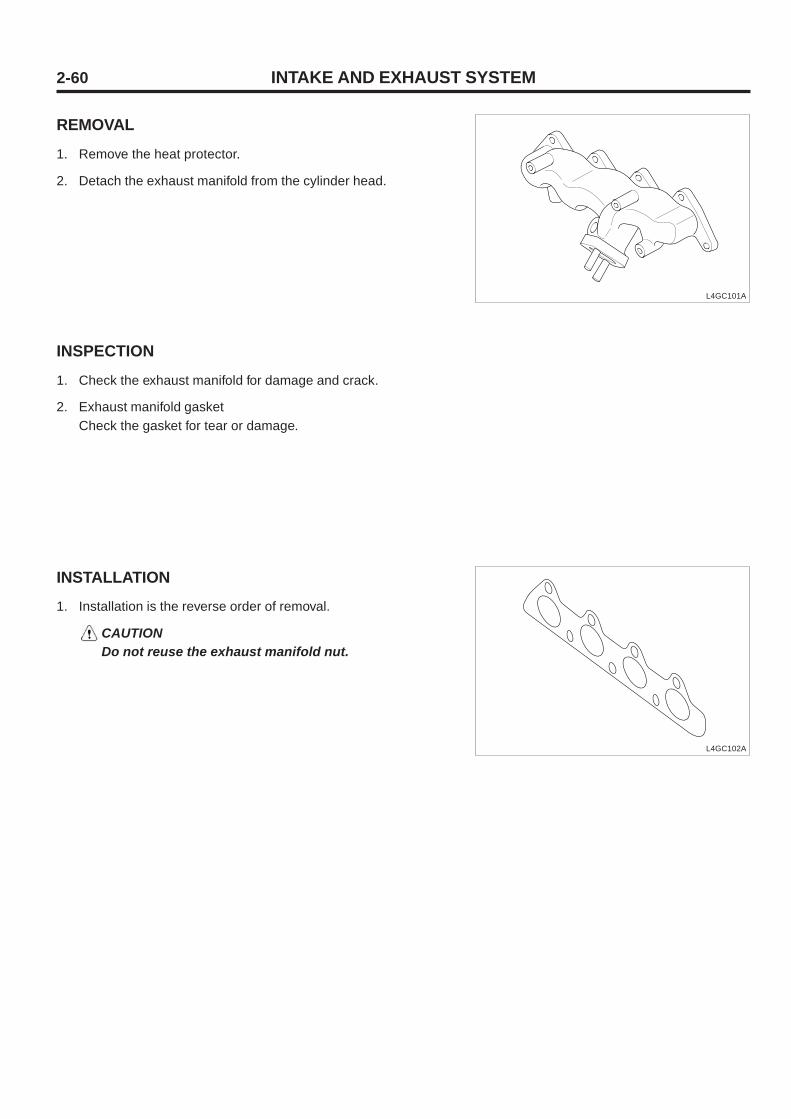
REMOVAL
1. Remove the heat protector.
2. Detach the exhaust manifold from the cylinder head.
INSPECTION
1. Check the exhaust manifold for damage and crack.
2. Exhaust manifold gasketCheck the gasket for tear or damage.
L4GC101A
L4GC102A
INSTALLATION
1. Installation is the reverse order of removal.
CAUTIONDo not reuse the exhaust manifold nut.
CYLINDER HEAD ASSEMBLY 2-61
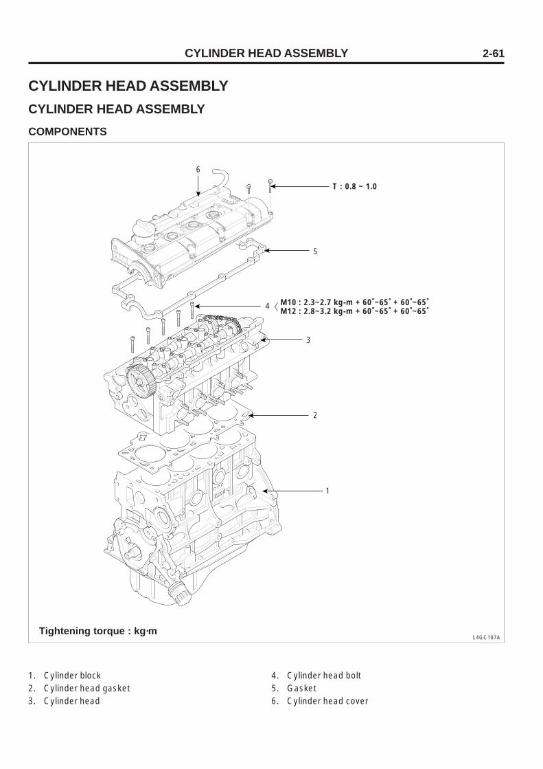
CYLINDER HEAD ASSEMBLYCYLINDER HEAD ASSEMBLYCOMPONENTS
L4GC107ATightening torque : kg·m
1. Cylinder block2. Cylinder head gasket3. Cylinder head
4. Cylinder head bolt5. Gasket6. Cylinder head cover
T : 0.8 ~ 1.0
4
1
6
5
M10 : 2.3~2.7 kg-m + 60˚~65˚ + 60˚~65˚M12 : 2.8~3.2 kg-m + 60˚~65˚ + 60˚~65˚
3
2
CYLINDER HEAD ASSEMBLY2-62
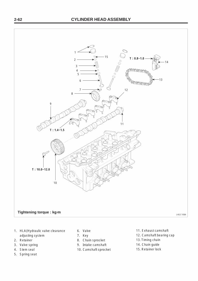
L4GC108ATightening torque : kg·m
1. HLA(Hydraulic valve clearanceadjusting system
2. Retainer3. Valve spring4. Stem seal5. Spring seat
6. Valve7. Key8. Chain sprocket9. Intake camshaft10. Camshaft sprocket
11. Exhaust camshaft12. Camshaft bearing cap13. Timing chain14. Chain guide15. Retainer lock
T : 1.4~1.5
T : 10.0~12.0
T : 0.8~1.0
11
12
14
13
10
1
152
3
45
6
78
9
CYLINDER HEAD ASSEMBLY 2-63
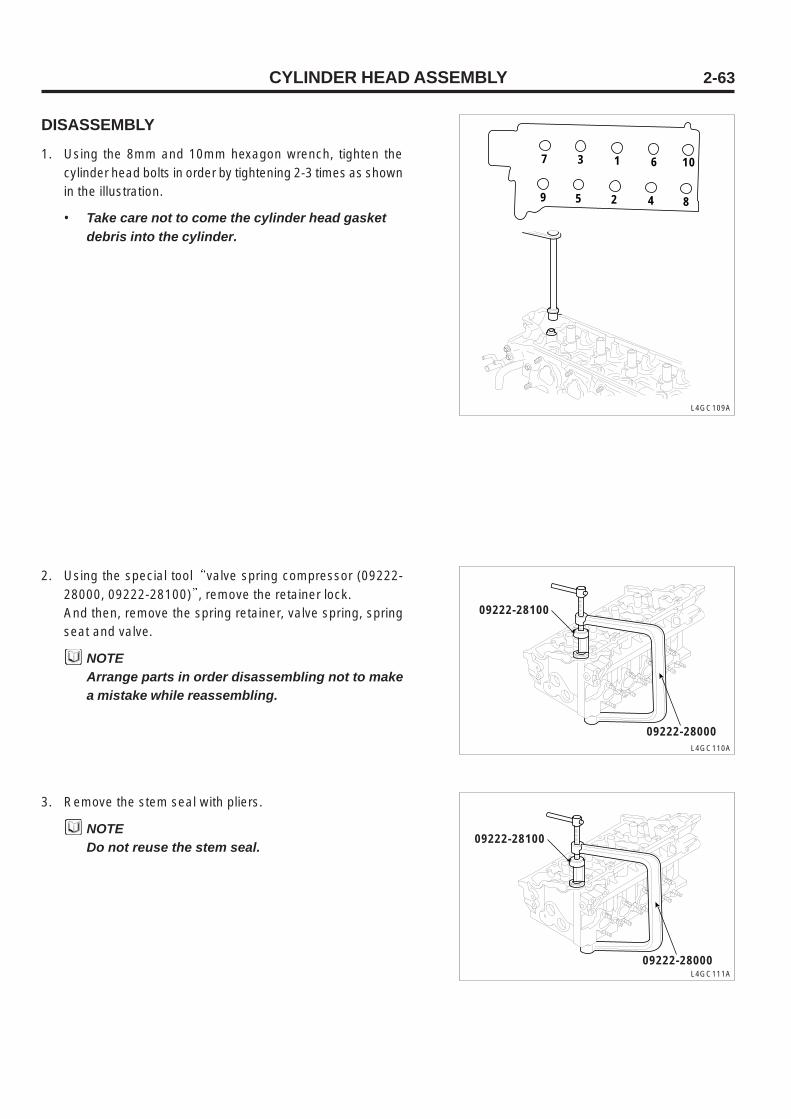
DISASSEMBLY
1. Using the 8mm and 10mm hexagon wrench, tighten thecylinder head bolts in order by tightening 2-3 times as shownin the illustration.
• Take care not to come the cylinder head gasketdebris into the cylinder.
L4GC110A
2. Using the special tool valve spring compressor (09222-28000, 09222-28100) , remove the retainer lock.And then, remove the spring retainer, valve spring, springseat and valve.
NOTEArrange parts in order disassembling not to makea mistake while reassembling.
L4GC111A
3. Remove the stem seal with pliers.
NOTEDo not reuse the stem seal.
L4GC109A
09222-28100
09222-28000
09222-28100
09222-28000
7 3 1 6 10
9 5 2 4 8

CYLINDER HEAD ASSEMBLY2-64
INSPECTION
CYLINDER HEAD
1. Check the cylinder head for crack, damage and leak.
2. Clean out fur, adhesive and accumulated carbon and aftercleaning the oil passage, bleed the passage with com-pressed air to check it for clogging.
3. Using a square, check the cylinder head gasket for flat-ness from shown in the illustration. If any flatness is out ofthe limit, replace the cylinder head or slightly cut the cylin-der head gasket surface.
Standard
Limit
0.03mm or less
0.06mm
Flatness of cylinderhead gasket surface
VALVE
1. Clean the valve with a wire brush.
2. Check each valve for wear and damage and inspect thehead and stem for torsion.If the stem end is cave or worn, trim it.At this time, trim it least.Also, trim the valve surface.If the margin is less than the limit, replace the valve.
Intake
Exhaust
Intake
Exhaust
1.15mm
1.35mm
0.8mm
1.0mm
Standard
Limit
Valve margin L4GC113A
L4GC112A
Margin
L4GC114A
CYLINDER HEAD ASSEMBLY 2-65
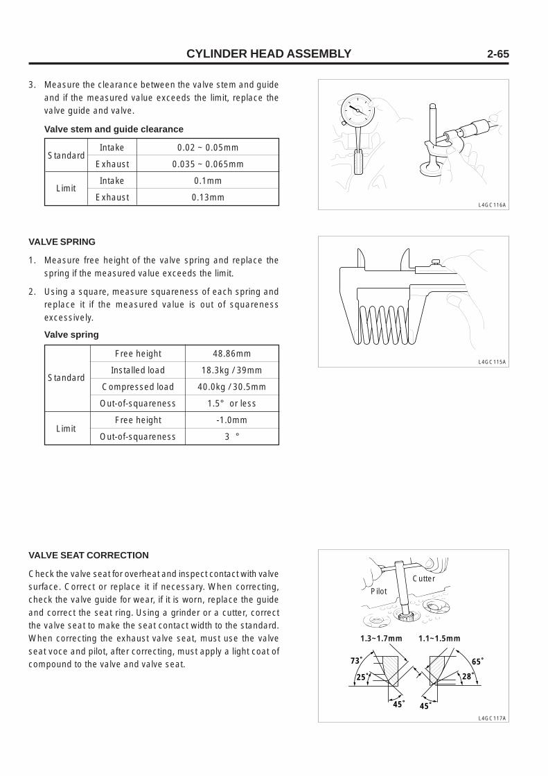
Intake
Exhaust
Intake
Exhaust
0.02 ~ 0.05mm
0.035 ~ 0.065mm
0.1mm
0.13mm
Standard
Limit
Valve stem and guide clearance
L4GC116A
3. Measure the clearance between the valve stem and guideand if the measured value exceeds the limit, replace thevalve guide and valve.
VALVE SPRING
1. Measure free height of the valve spring and replace thespring if the measured value exceeds the limit.
2. Using a square, measure squareness of each spring andreplace it if the measured value is out of squarenessexcessively.
L4GC115AFree height
Installed load
Compressed load
Out-of-squareness
Free height
Out-of-squareness
48.86mm
18.3kg / 39mm
40.0kg / 30.5mm
1.5° or less
-1.0mm
3 °
Standard
Limit
Valve spring
VALVE SEAT CORRECTION
Check the valve seat for overheat and inspect contact with valvesurface. Correct or replace it if necessary. When correcting,check the valve guide for wear, if it is worn, replace the guideand correct the seat ring. Using a grinder or a cutter, correctthe valve seat to make the seat contact width to the standard.When correcting the exhaust valve seat, must use the valveseat voce and pilot, after correcting, must apply a light coat ofcompound to the valve and valve seat.
L4GC117A
Cutter
Pilot
1.3~1.7mm 1.1~1.5mm
73˚
25˚
65˚
28˚
45˚ 45˚

CYLINDER HEAD ASSEMBLY2-66
VALVE SEAT RING REPLACEMENT
1. If the valve seat insert is excessively worn, cut the insertring wall as shown in the illustration A using a valve seatcutter at a normal temperature.
Valve seat ring oversize
ItemCylinder insert height
H (mm)Size(mm) Size mark
Cylinder head I.D(mm)
33.330 ~ 33.325
33.600 ~ 33.625
28.800 ~ 28.821
29.100 ~ 29.121
7.5 ~ 7.7
7.8 ~ 8.0
7.9 ~ 8.1
8.2 ~ 8.4
0.3 OS
0.6 OS
0.3 OS
0.6 OS
30
60
30
60
Intake valve seat ring
L4GC118A
2. After removing the seat ring, Cut the seat insert bore assame size as the following table as shown in the illustration
A using a reamer or cutter.
3. Heat the cylinder head to 250°C and press-fit the oversizeseat.At this time the oversize seat ring maintains a normal roomtemperature.After installing a new valve seat, correct the valve seatsurface.
Exhaust valve seat ring
D
A B
0.5~1.0mm
0.15~0.3mm
0.3mmR
New hole
Old holeH
Removal

CYLINDER HEAD ASSEMBLY 2-67
VALVE GUIDE REPLACEMENT
Because the valve guide is press-fitted, replace the valve guideas the following procedures using a valve guide installer orproper tool.
1. Remove the valve guide pressed toward cylinder block us-ing a push rod of valve guide installer.
2. Cut the valve guide insert bore of the cylinder head to thevalve guide oversize.
3. Press-fit the valve guide using a valve guide installer orproper tool. When using a valve guide installer, Use a valveguide installer to press-fit the valve guide to the specifiedheight.
4. When installing, start from top of valve guide cylinder head.Be sure that the intake valve guide is not same size withthe exhaust valve guide. (Intake valve guide : 46.0mm, ex-haust valve guide : 54.5mm)
5. After installing the valve guide, insert a new valve and checkfor perturbation.
6. When replacing the valve guide, check the valve for con-tact and correct the valve seat if necessary.
Size
0.05 OS
0.25 OS
0.50 OS
Cylinder head bore size
11.05 ~ 11.068mm
11.25 ~ 11.268mm
11.50 ~ 11.518mm
Valve guide oversize
Size mark
5
25
50
09221-22000A
09221-22000BL4GC119A

CYLINDER HEAD ASSEMBLY2-68
4. Taking care not to press the valve stem seal down to theretainer bottom, press-fit the spring with the special tool
valve spring compressor (09222-28000, 09222-28100)and put the retainer lock in.Remove spring compressor after pisition retainer lockexactly.
5. Hit the end of valve two or three times by rubber malet, sothat valve and retainer lock is in position.
6. Assembly the HLA using by hand.
L4GC121A
L4GC120A
VALVE1. After installing the spring seat, insert the stem seal to the
valve guide.Install the stem seal by tapping on it with the special tool
valve stem oil seal installer (09222-22001)Wrong installation of the seal can affect oil leak from thevalve guide, so use the special tool to install it to exactposition and take care not to twist it. Do not reuse it.
2. After applying engine oil to each valve, insert the valve intothe valve guide.
3. Install the spring and spring retainer. Face the enamel-plated side toward the valve spring retainer side.
L4GC122A
09222-22001
09222-28100
09222-28000
Enamel plate Spring retainer
Valve stem sealSpring
Valve spring seat
ASSEMBLY
CAUTION• Prior to assembly, clean each component.• Apply a new engine oil to the perturbation part
and rotation part.• Replace a new oil seal.

CYLINDER HEAD ASSEMBLY 2-69
HEAD1. Clean out all gasket surfaces of the cylinder block and cyl-
inder head.
2. Put new cylinder head gaskets on the cylinder block withthe identification marks faced upward. Do not apply seal-ant to the gasket and do not reuse the used cylinder headgasket. Take care not to make a mistake of gasket.
3. Put the cylinder head on the cylinder block.
4. Apply a slight coat of engine oil to the spiral portion of bolt.
5. Insert the washer to the bolt and insert it to the cylinderhead.
6. Using the 8mm and 10mm hexagon wrench, install the cyl-inder head bolt as shown in the illustration.
L4GC123A
M10
M12
2.5kg·m + (60°~ 65°) + (60°~ 65°)
3.0kg·m + (60°~ 65°) + (60°~ 65°)
Cylinder head bolt
8 6 1 3 9
10 4 2 5 7
M12
7. Install the camshafts.
8. Install the camshafts oil seal.
9. Install the camsprocket and timing belt.
10. Install the head cover.
TIMING SYSTEM2-70
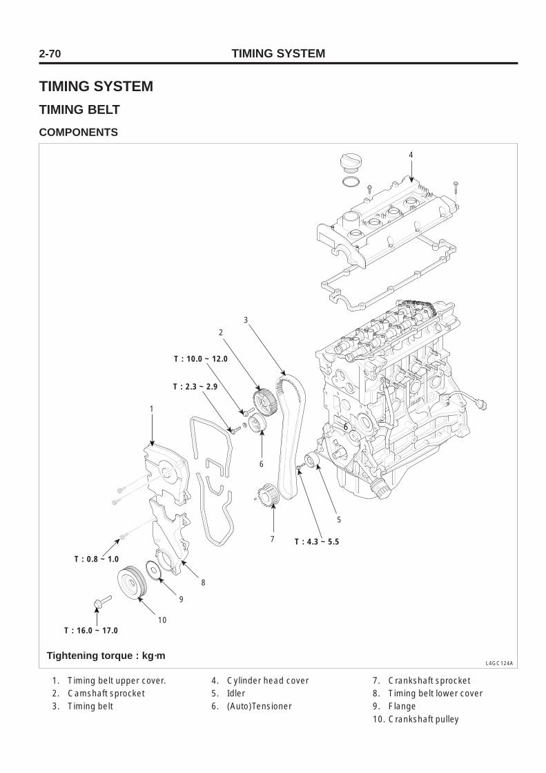
TIMING SYSTEMTIMING BELTCOMPONENTS
L4GC124A
1. Timing belt upper cover.2. Camshaft sprocket3. Timing belt
4. Cylinder head cover5. Idler6. (Auto)Tensioner
7. Crankshaft sprocket8. Timing belt lower cover9. Flange10. Crankshaft pulley
Tightening torque : kg·m
6
7
8
9
10
T : 4.3 ~ 5.5
T : 16.0 ~ 17.0
T : 0.8 ~ 1.0
T : 10.0 ~ 12.0
T : 2.3 ~ 2.9
5
6
2
3
1
4

TIMING SYSTEM 2-71
REMOVAL
1. Temporarily loosen the water pump pulley bolts.
2. Loosen the alternator bolt and remove the belt.
3. Remove the water pump pulley.
4. Remove the timing belt upper cover.
L4GC125A
L4GC127A
6. Remove the crankshaft pulley.
7. Remove the crankshaft flange.
8. Remove the timing belt lower cover.
Water pump pulley
drive belt
Tensioner pulley
Idler pulley
L4GC154A
5. Turn the crankshaft, and align its groove with timing markT .
L4GC126A
9. Remove the timing belt tensioner pulley.

TIMING SYSTEM2-72
10. Remove the timing belt form the camshaft sprocket.
NOTEWhen reusing the timing belt, put an arrow markon the rotation direction (or front side of engine)before removal to help re-install it to original in-stallation direction.
L4GC128A
11. Remove the idler.
12. Remove the crankshaft sprocket.
13. Remove the cylinder head cover and remove camshaftsprocket.
TIMING SYSTEM 2-73
INSPECTION
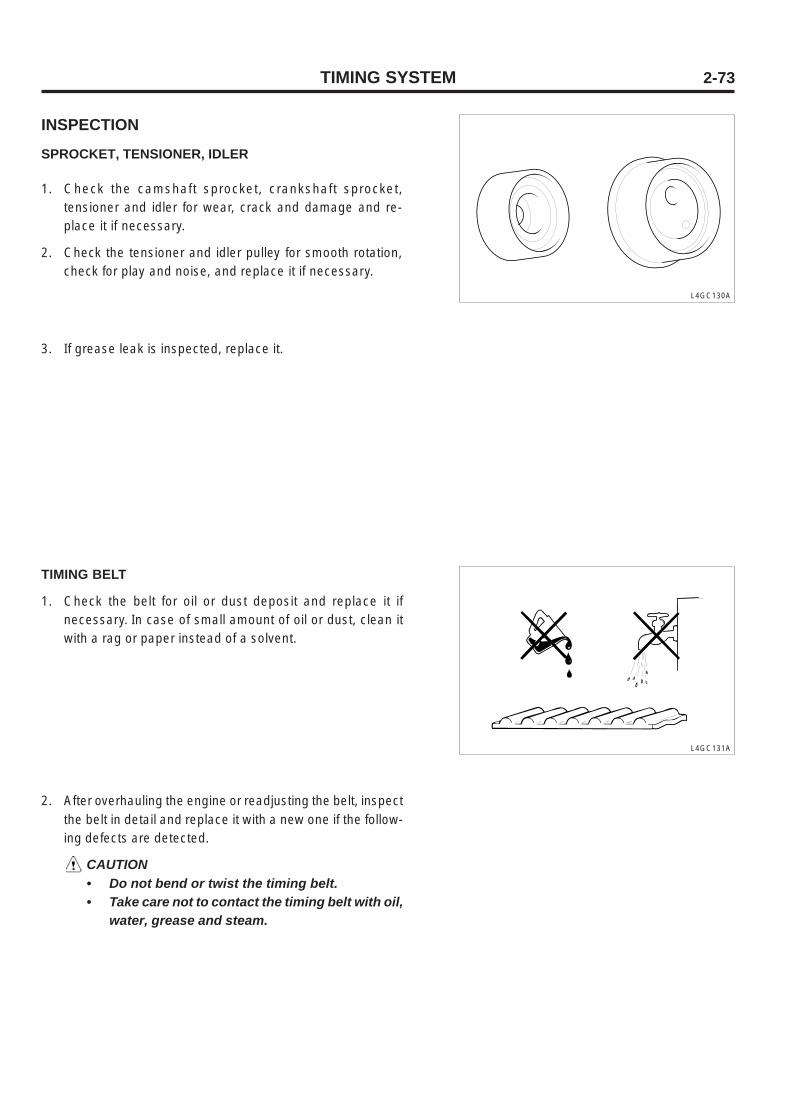
SPROCKET, TENSIONER, IDLER
1. Check the camshaft sprocket, crankshaft sprocket,tensioner and idler for wear, crack and damage and re-place it if necessary.
2. Check the tensioner and idler pulley for smooth rotation,check for play and noise, and replace it if necessary.
L4GC130A
3. If grease leak is inspected, replace it.
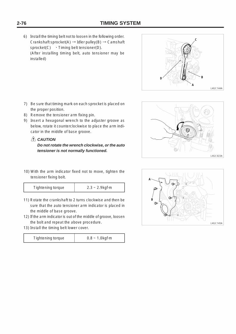
TIMING BELT
1. Check the belt for oil or dust deposit and replace it ifnecessary. In case of small amount of oil or dust, clean itwith a rag or paper instead of a solvent.
L4GC131A
2. After overhauling the engine or readjusting the belt, inspectthe belt in detail and replace it with a new one if the follow-ing defects are detected.
CAUTION• Do not bend or twist the timing belt.• Take care not to contact the timing belt with oil,
water, grease and steam.

TIMING SYSTEM2-74
Description Specification
1. Back side rubber is hardened
2. Back side rubber is cracked
3. Canvas is cracked or detached
4. Tooth is excessively worn out (initial step)
5. Tooth is excessively worn out (final step)
6. Tooth bottom is cracked
7. Tooth is missing
8. The side of belt is severely worn out
9. The side of belt is cracked
Glossy back side. Due to non-elasticityand hardening, when pressing it withthe tip of a finger, there is no sign of it.
NOTEIn case of normal belt,it is cut precisely as if cutwith a sharp cutter
L4GC132A
L4GC133A
L4GC134A L4GC135A
L4GC137A
L4GC138A
L4GC139A
L4GC140A
L4GC136A
L4GC141A
L4GC142A
Tooth loaded from canvas isworn (elastic canvas fiber rubber isworn, color is faded in white, canvasstructure is deformed)
Tooth loaded from canvas is wornand rubber is worn off (toothwidth is narrowed)
Cracked Cracked
DetachedDetached
Worn out(loaded side)
Rubber is worn off
Crack
Tooth is missing and canvas fiber is worn off
Rounding belt side
Abnormal wear(Canvas fiber is cracked)

TIMING SYSTEM 2-75
ASSEMBLY
1. Install the crankshaft sprocket taking care of installationdirection as shown in the illustration.
L4GC155A
2. Install the camshaft sprocket and tighten the bolt to thespecified torque.
Camshaft sprocket bolt 10 ~ 12kg·m
3. Install the idler and tighten the bolt to the specified torque.
Idler fixing bolt 4.3 ~ 5.5kg·m
4. With no.1 cylinder piston to the dead point of compressionstroke, align the timing mark on the camshaft sprocket andtiming mark on the crankshaft sprocket.
1) After installing the tensioner, spring and spacer andtightening the bolt temporarily, tighten the long holeshaft washer of tensioner and bolt.
2) Install the spring bottom end to the front case as shownin the illustration.
3) Install the flange and crankshaft sprocket taking careof installation direction and then tighten the washer andbolt temporarily.
4) When aligning the timing marks, after turning the cam-shaft sprocket to place the red timing mark on the camcap in the middle of the knock pin 4.5 bore, align thistiming mark with the timing mark on the front case byrotating the shaft sprocket.
5) Install the belt with the timing aligned as shown in theillustration. (When installing, start from the belt tensionside and then install the belt by pressing the tensioner.
CAUTIONWhen no.1 piston is at TDC, if the camshaftsprocket mark is not aligned with head mark,interference between piston and valve occurs.So take care of timing aligning.
A
A
Timing mark
L4GC156A
TIMING SYSTEM2-76
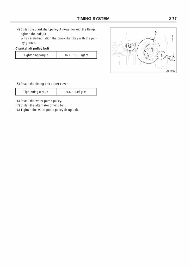
6) Install the timing belt not to loosen in the following order.Crankshaft sprocket(A) Idler pulley(B) Camshaftsprocket(C) Timing belt tensioner(D).(After installing timing belt, auto tensioner may beinstalled)
7) Be sure that timing mark on each sprocket is placed onthe proper position.
8) Remove the tensioner arm fixing pin.9) Insert a hexagonal wrench to the adjuster groove as
below, rotate it counterclockwise to place the arm indi-cator in the middle of base groove.
CAUTIONDo not rotate the wrench clockwise, or the autotensioner is not normally functioned.
L4GC144A
10) With the arm indicator fixed not to move, tighten thetensioner fixing bolt.
L4GC023A
A
B
C
D
Tightening torque 2.3 ~ 2.9kgf·m
11) Rotate the crankshaft to 2 turns clockwise and then besure that the auto tensioner arm indicator is placed inthe middle of base groove.
12) If the arm indicator is out of the middle of groove, loosenthe bolt and repeat the above procedure.
13) Install the timing belt lower cover.
Tightening torque 0.8 ~ 1.0kgf·m
A
B
L4GC145A
TIMING SYSTEM 2-77
14) Install the crankshaft pulley(A) together with the flange,tighten the bolt(B).When installing, align the crankshaft key with the pul-ley groove.
A
B
L4GC146A
15) Install the timing belt upper cover.
Tightening torque 0.8 ~ 1.0kgf·m
Tightening torque 16.0 ~ 17.0kgf·m
16) Install the water pump pulley.17) Install the alternator driving belt.18) Tighten the water pump pulley fixing bolt.
Crankshaft pulley bolt
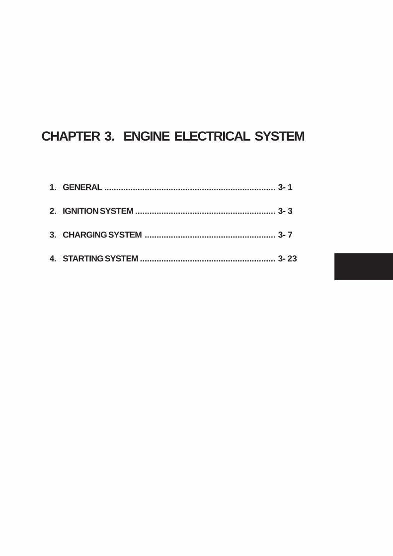
1. GENERAL ........................................................................ 3- 1
2. IGNITION SYSTEM ........................................................... 3- 3
3. CHARGING SYSTEM ....................................................... 3- 7
4. STARTING SYSTEM ......................................................... 3- 23
CHAPTER 3. ENGINE ELECTRICAL SYSTEM

1. GENERAL ........................................................................ 3- 1
2. IGNITION SYSTEM ........................................................... 3- 3
3. CHARGING SYSTEM ....................................................... 3- 9
4. STARTING SYSTEM ......................................................... 3- 25
CHAPTER 3. ENGINE ELECTRICAL SYSTEM
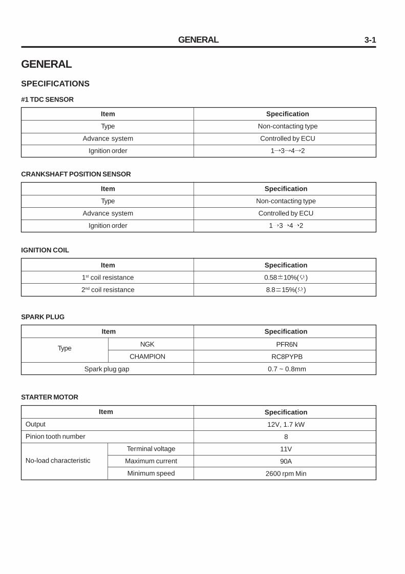
3-1
GENERALSPECIFICATIONS
STARTER MOTOR
Output
Pinion tooth number
Item Specification
12V, 1.7 kW
8
11V
90A
2600 rpm Min
GENERAL
#1 TDC SENSOR
Item
Type
Advance system
Ignition order
Specification
Non-contacting type
Controlled by ECU
1 3 4 2
CRANKSHAFT POSITION SENSOR
Item
Type
Advance system
Ignition order
Specification
Non-contacting type
Controlled by ECU
1 3 4 2
IGNITION COIL
Item
1st coil resistance
2nd coil resistance
Specification
0.58 10%( )
8.8 15%( )
SPARK PLUG
PFR6N
RC8PYPB
0.7 ~ 0.8mm
Item Specification
Type
Spark plug gap
NGK
CHAMPION
No-load characteristic
Terminal voltage
Maximum current
Minimum speed
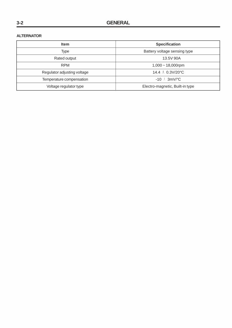
3-2 GENERAL
ALTERNATOR
Item
Type
Rated output
RPM
Regulator adjusting voltage
Temperature compensation
Voltage regulator type
Specification
Battery voltage sensing type
13.5V 90A
1,000 ~ 18,000rpm
14.4 0.3V/20°C
-10 3mV/°C
Electro-magnetic, Built-in type

3-3
IGNITION SYSTEM
GENERAL1. If the ignition switch is ON, the battery voltage is supplied
to 1st coil of ignition coil.
2. By rotation of the crank position sensor wheel, ignition sig-nal in ECU is actuated the power transistor and repeat groundor shut off of 1st current of ignition coil.
3. This causes high pressure in 2nd coil, the induced currentfrom ignition coil to 2nd, coil is grounded though the sparkplug and each cylinder is ignited.
TROUBLESHOOTINGWhen it is hard to start engine, there can be problem with fuelsystem or engine itself as well as ignition system.Because main function of ignition system is to supply suffi-cient electronic spark at a proper timing, when inspecting thissystem, necessarily contains spark checking and ignition tim-ing measurement. When inspecting ignition system installed tothe vehicle, check for possible trouble symptoms from faultycircuit, power, 1st low voltage circuit, high voltage circuit, etc..
1. ENGINE IS NOT STARTED OR HARD TO START.(CRANKING O.K.)
A spark of spark plug is weak or not at all1) Check Ignition coil2) Crankshaft position sensor3) Spark plug
A spark is normalCheck ignition timing (Ignition timing is automatically con-trolled by ECU)
2. IDLING IS UNSTABLE- Spark plug- Ignition timing- Ignition coil
3. ACCELERATION IS INSUFFICIENT.- Check Ignition timing
4. ENGINE IS OVERHEATED AND FUEL CONSUMPTION ISEXCESSIVE.- Check Ignition timing
IGNITION SYSTEM

3-4 IGNITION SYSTEM
INSPECTION OF IGNITION TIMING1. Inspection condition
Coolant temperature : 80-90°C(At normal temperature)Lamp, cooling fan and all accessories : OFFTransaxle : In neutral position (Auto : N)Parking brake : ON
2. Inspection1) Connect the timing light.2) After inserting the clip backward the connector, con-
nect the tachometer with the special tool (09273-24000)
CAUTIONTake care not to disconnect the connector.
L4GC154A
1A. 1ST coil resistance measurement
1ST coil resistance 0.5° 0.05Ω
Measure resistance between no.1 and no.2 terminals of ig-nition coil.
2. 2ST coil resistance measurementMeasure resistance between high pressure terminals.
2ST coil resistance 12.1 1.8KΩ
L4GC301A
CAUTIONWhen measuring 2nd coil resistance, remove the ig-nition coil connector.
1 2
INSPECTION OF IGNITION COIL1. 1ST coil resistance measurement
Measure resistance between no.1 and no.3 terminals of ig-nition coil. (For no.1 and no.4 cylinders)And measure resistance between no.3 and no.2 terminalsof ignition coil. (For no.2 and no.3 cylinders)

3-5
INSPECTION OF SPARK PLUGInspection and clean
1. Disconnect the ignition coil from the spark plug.
2. Remove all spark plugs from the cylinder head using a sparkplug wrench.
CAUTIONTake care not to come foreign materials into spark-plug mounting hole.
3. Check the spark plug as below.1) Insulator broken2) Terminal worn3) Carbon deposit4) Gasket damaged or broken5) Porcelain insulator of spark plug clearance
L4GC302A
L4GC303A
L4GC304A
4. Check the plug clearance using a plug clearance gauge andif the value is not within the specified values, adjust it bybending the ground clearance. When installing a new sparkplug, install it after checking the uniform plug clearance.
Spark plug clearance 0.7 ~ 0.8mm
L4GC305A
5. Install the spark plug and tighten it to the specified torque.Take care not to over tighten it to prevent cylinder headthreads from damage.
Tightening torque 2 ~ 3kg·m
IGNITION SYSTEM
2
3 4 5
1
Clearance

3-6 IGNITION SYSTEM
SPARK PLUG ANALYSIS
State
Description
Contact point iswhite
Contact point isblack
•Density of the fuel mixture is thick•Lack of air intake
SPARK PLUG TEST
After connecting the spark plug to the ignition coil, connect theouter terminal(main body) to the ground and crank the engine.Because the discharging clearance is narrow in the air, onlyslight spark will arise. But if the spark plug is normal, sparkarises at emission clearance (between terminals), and if thespark plug is defective, spark does not arise because insula-tion is damaged.
• Density of the fuel mixture is thin•Ignition timing is fast•Spark plug is tight•Lack of torque
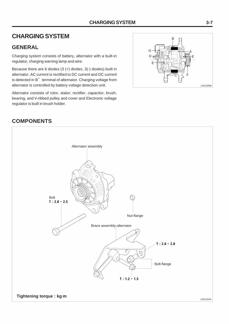
3-7
CHARGING SYSTEM
GENERALCharging system consists of battery, alternator with a built-inregulator, charging warning lamp and wire.
Because there are 6 diodes (3 (+) diodes, 3(-) diodes) built inalternator, AC current is rectified to DC current and DC currentis detected in B terminal of alternator. Charging voltage fromalternator is controlled by battery voltage detection unit.
Alternator consists of rotor, stator, rectifier, capacitor, brush,bearing, and V-ribbed pulley and cover and Electronic voltageregulator is built in brush holder.
L4GC309A
COMPONENTS
L4GC310A
CHARGING SYSTEM
A
B
C
D E
E
G
F
Tightening torque : kg·m
Alternator assembly
BoltT : 2.0 ~ 2.5
Nut-flange
Brace assembly-alternator
Bolt-flange
T : 2.0 ~ 2.8
T : 1.2 ~ 1.5
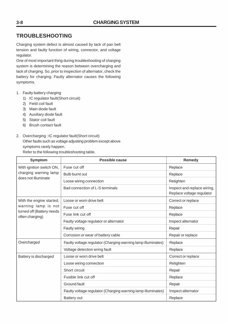
3-8
TROUBLESHOOTINGCharging system defect is almost caused by lack of pan belttension and faulty function of wiring, connector, and voltageregulator.One of most important thing during troubleshooting of chargingsystem is determining the reason between overcharging andlack of charging. So, prior to inspection of alternator, check thebattery for charging. Faulty alternator causes the followingsymptoms.
1. Faulty battery charging1) IC regulator fault(Short circuit)2) Field coil fault3) Main diode fault4) Auxiliary diode fault5) Stator coil fault6) Brush contact fault
2. Overcharging : IC regulator fault(Short circuit)Other faults such as voltage adjusting problem except abovesymptoms rarely happen.Refer to the following troubleshooting table.
Symptom Remedy
With ignition switch ON,charging warning lampdoes not illuminate
Fuse cut off
Bulb burnt out
Loose wiring connection
Bad connection of L-S terminals
Replace
Replace
Retighten
Inspect and replace wiring,Replace voltage regulator
Possible cause
With the engine started,warning lamp is notturned off (Battery needsoften charging)
Loose or worn drive belt
Fuse cut off
Fuse link cut off
Faulty voltage regulator or alternator
Faulty wiring
Corrosion or wear of battery cable
Correct or replace
Replace
Replace
Inspect alternator
Repair
Repair or replace
Overcharged Faulty voltage regulator (Charging warning lamp illuminates)
Voltage detection wring fault
Loose or worn drive belt
Loose wiring connection
Short circuit
Fusible link cut off
Ground fault
Faulty voltage regulator (Charging warning lamp illuminates)
Battery out
Replace
Replace
Correct or replace
Retighten
Repair
Replace
Repair
Inspect alternator
Replace
Battery is discharged
CHARGING SYSTEM

3-9CHARGING SYSTEM
TROUBLESHOOTING PROCEDUREINSPECTION BEFORE STARTING
1. Charging warning lamp inspection
L4GC311A
2. Alternator and drive belt tension inspection
L4GC312A
Alternator female current supply circuit cut off,Alternator charging fault
Does charging warning lamp illuminate with ignition switch in IG position?
Illuminated
OK
Not illuminated
Replace alternator
If rotation is abnormally delivered to generate power, battery is discharged and belt is slipped at low speed and overload
Is there a deflection of 10mm when pressing the belt with 10kg f ?
Normal
OK
Loose belt
Re-adjust tension
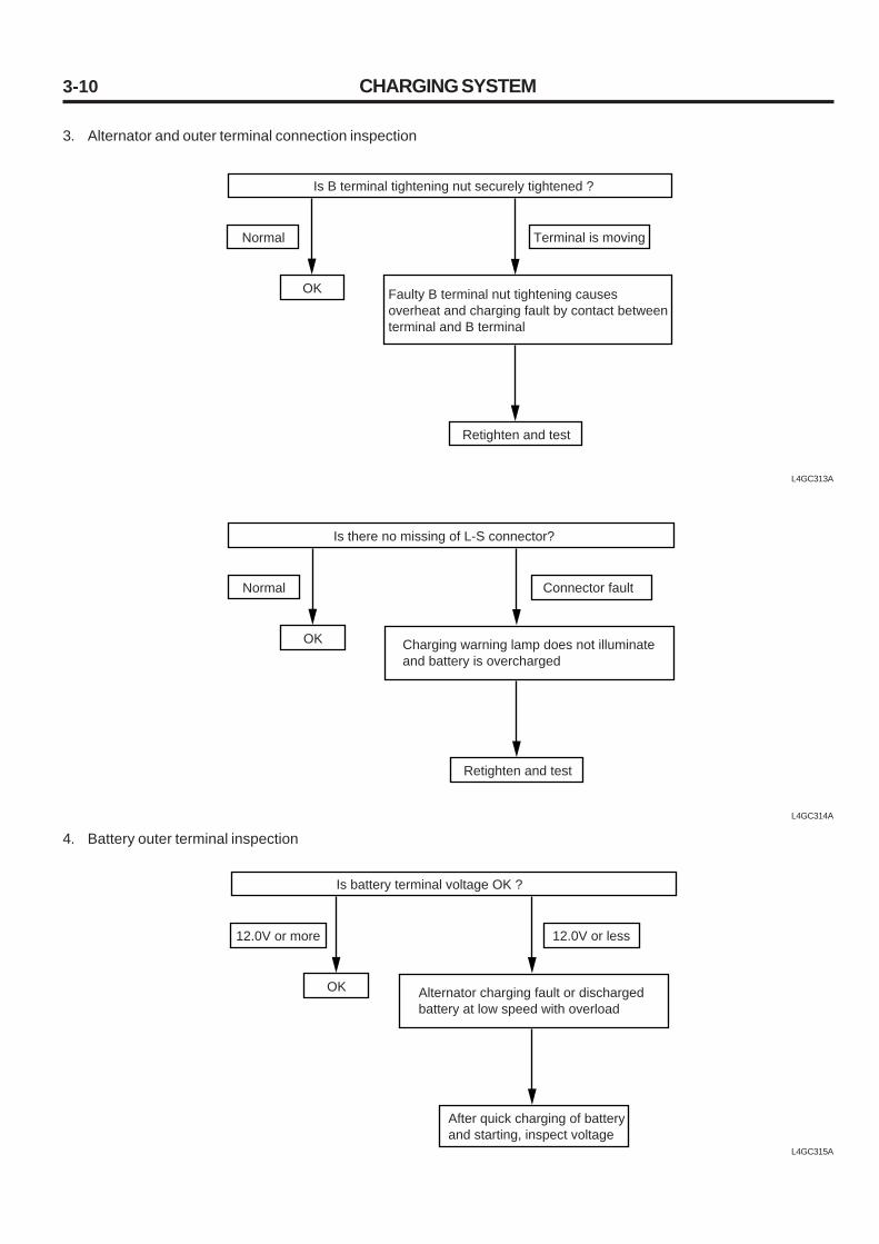
3-10
L4GC314A
4. Battery outer terminal inspection
L4GC315A
CHARGING SYSTEM
3. Alternator and outer terminal connection inspection
L4GC313A
Faulty B terminal nut tightening causes overheat and charging fault by contact between terminal and B terminal
Is B terminal tightening nut securely tightened ?
Normal
OK
Terminal is moving
Retighten and test
Charging warning lamp does not illuminate and battery is overcharged
Is there no missing of L-S connector?
Normal
OK
Connector fault
Retighten and test
Alternator charging fault or discharged battery at low speed with overload
Is battery terminal voltage OK ?
12.0V or more
OK
12.0V or less
After quick charging of battery and starting, inspect voltage

3-11
INSPECTION AFTER STARTING
1. Inspection of alternator charging warning lamp operation test
L4GC317A
2. When starting, belt slip and noise inspection
L4GC318A
3. Inspection of battery voltage at idling(At this time charge battery only)
L4GC319A
CHARGING SYSTEM
(Check for power generation)
Generator female circuit is normal but generator component is faulty
Is charging warning lamp turned OFF?
Illuminated
OK
Not illuminated
Replace generator
See "INSPECTION BEFORE STARTING" to inspect belt slippage and readjust tension
Is there any noise heard from belt?
Normal
OK
Whistling sound heard
No generation, overcharging, and insufficient output owing to inner defection of Generator
Is battery terminal voltage OK ?
13.5V-15.0V
OK
Out of standard
Inspect after removal

3-12
DROP OF ELECTRIC PRESSURE TESTOF ALTERNATOR OUTPUT WIREThis test is to check that wiring is correctly connected betweenthe alternator B terminal and battery (+) terminal.
PREPARATION
1. Turn the ignition switch OFF.
2. Disconnect the battery ground cable.
3. Disconnect the alternator output wire from the alternatorB terminal.
4. Connect a DC ampere meter (0-100A) between the terminaland the disconnected output wire.Connect (+) lead wire to the terminal B and (-) lead wireto the disconnected output wire.
NOTEIn case of using a clamp type ammeter, it is possibleto measure current without disconnecting theharness.
5. Connect a digital voltmeter between the alternator Bterminal and the battery (+) terminal.Connect (+) lead wire to the terminal B and (-) lead wireto the battery (+) terminal.
6. Connect the battery ground cable.
7. Be sure that the hood is opened.
CHARGING SYSTEM
TEST
1. Start the engine.
2. Repeating ON and OFF of headlight and small light, adjustthe engine speed until an ammeter reads 20A and at thattime measure voltage.
L4GC320A
Alternator
Voltmeter
Ammeter
Battery
V
"B" terminal
3-13CHARGING SYSTEM
OUTPUT CURRENT TESTThis test is to check that the alternator output current is identi-fied with the rated current.
PREPARATION
1. Prior to test, inspect the following items and repair ifnecessary.
1) Be sure that the battery installed in the vehicle isnormal.(See Battery )
NOTEWhen measuring output current, necessarily usea slightly discharged battery. Fully charged bat-tery is not enough to use for correct test owingto insufficient load.
2) Inspect the drive belt for tension. (See Engine body )
2. Turn the ignition switch OFF.
3. Disconnect the battery ground cable.
4. Disconnect the alternator output wire from the alternatorB terminal.
RESULT
1. If voltmeter reading is within the standard, it is normal.
Test voltage Maximum 0.2V
2. If voltmeter reading is more than the standard, mostly wir-ing is faulty. In this case, inspect wirings between the alter-nator and the battery (+) terminal as well as between thealternator B terminal and the fusible link.
3. Also prior to re-test, check and repair the connecting partfor looseness and the harness for discoloration byoverheating.
4. After test, adjust the engine speed at idle and turn the lightand ignition switch OFF.
5. Disconnect the battery ground cable.
6. Disconnect the ammeter and voltmeter.
7. Connect the alternator output lead wire to the alternatorB terminal.
8. Connect the battery ground cable.
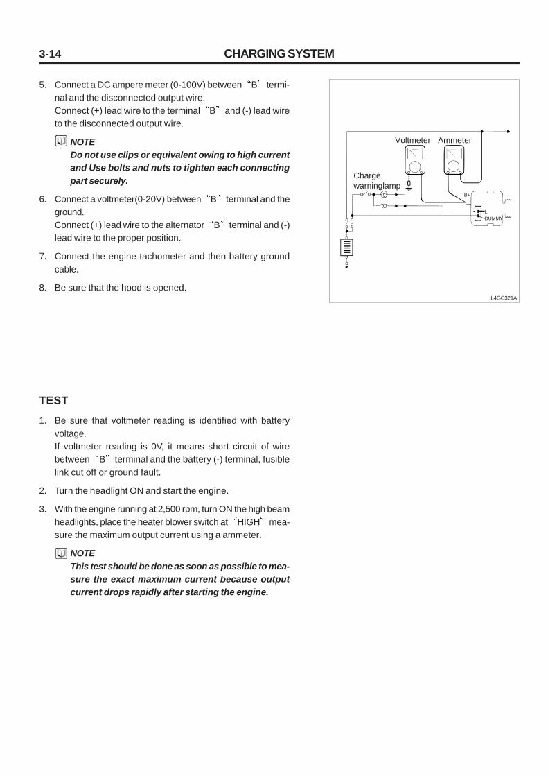
3-14 CHARGING SYSTEM
5. Connect a DC ampere meter (0-100V) between B termi-nal and the disconnected output wire.Connect (+) lead wire to the terminal B and (-) lead wireto the disconnected output wire.
NOTEDo not use clips or equivalent owing to high currentand Use bolts and nuts to tighten each connectingpart securely.
6. Connect a voltmeter(0-20V) between B terminal and theground.Connect (+) lead wire to the alternator B terminal and (-)lead wire to the proper position.
7. Connect the engine tachometer and then battery groundcable.
8. Be sure that the hood is opened.L4GC321A
TEST
1. Be sure that voltmeter reading is identified with batteryvoltage.If voltmeter reading is 0V, it means short circuit of wirebetween B terminal and the battery (-) terminal, fusiblelink cut off or ground fault.
2. Turn the headlight ON and start the engine.
3. With the engine running at 2,500 rpm, turn ON the high beamheadlights, place the heater blower switch at HIGH mea-sure the maximum output current using a ammeter.
NOTEThis test should be done as soon as possible to mea-sure the exact maximum current because outputcurrent drops rapidly after starting the engine.
L
B+
DUMMY
Voltmeter Ammeter
Charge warninglamp

3-15
RESULT
1. Ammeter reading should be higher than the limit. If the read-ing is low even though the alternator output wire is normal,remove the alternator from the vehicle and inspect it.
CHARGING SYSTEM
2. After test, adjust the engine speed at idle and turn the lightand ignition switch OFF.
3. Disconnect the battery ground cable.
4. Disconnect the ammeter and voltmeter.
5. Connect the alternator output lead wire to the alternatorB terminal.
6. Connect the battery ground cable.
Output current limit 70% of rated current
NOTE• The rated output current is represented on the
name plate in the alternator body.• Output current varies according to electrical load
or temperature of the alternator, so during test,lack of electrical load causes impossibility ofmeasuring the rated output current. In this case,turn on headlight to induce the battery discharg-ing or turn on other lights to increase the electri-cal load. If alternator temperature or ambient tem-perature is too high, it is impossible to measurethe rated output current, so prior to re-test, nec-essarily drop the temperature.
Ambient temperature ofvoltage regulator (°C)
Voltage adjust (V)
-20
20
60
80
14.2 ~ 15.4
13.8 ~ 15.0
13.4 ~ 14.6
13.2 ~ 14.4

3-16
1. Nut2. Pulley3. Bushing4. Front cover assembly5. Front bearing6. Bearing cover7. Bearing cover bolt
CHARGING SYSTEM
DISASSEMBLY AND INSTALLATION
L4GC322A
1 2
3
4
5
9
10
1211
1314
15
6
78
16
17
18
19
20
8. Rotor coil9. Rear bearing10. Bearing cover11. Stator coil12. Rear cover13. Through bolt14. Seal
15. Rectifier assembly16. Stud bolt17. Brush holder assembly18. Brush holder bolt19. Slip ring guide20. Cover

3-17
REMOVAL AND INSTALLATION
1. Disconnect the battery (A) terminal.
2. Disconnect the alternator B terminal and then the con-nector (A). Loosen the clip (B).
3. Loosen the alternator tension adjusting bolt (A) and the al-ternator fixing bolt (B).
4. Remove the belt by pressing inward the alternator.
5. Remove the alternator brocket.
6. Loosen the mounting and remove the alternator assembly.
7. Installation is reverse order of removal.
L4GC324A
CHARGING SYSTEM
A
B
L4GC323A
A
B
A BL4GC325A

3-18
4. Remove the nut, pulley and spacer.
L4GC328A
CHARGING SYSTEM
L4GC327A
L4GC329A
L4GC326A
DISASSEMBLY
1. After removing the mounting nuts (B), remove the genera-tor cover (A) using a screwdriver.
2. Loosen 3 mounting bolts (A) and disconnect the brush holderassembly (B).
3. Remove the slip ring guide (A).
B
A
B
A
A
A

3-19
5. Loosen 4 through bolts.
L4GC330A
L4GC048A
6. Separate the rotor and cover.
CHARGING SYSTEM
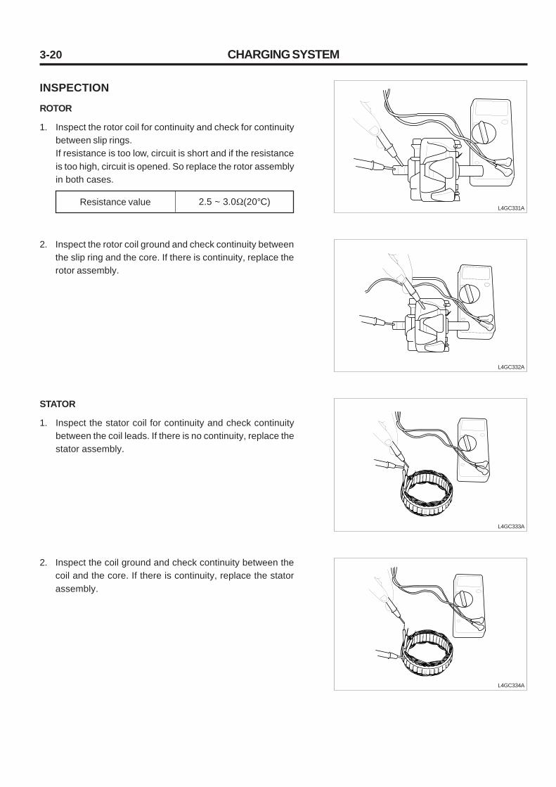
3-20
INSPECTION
ROTOR
1. Inspect the rotor coil for continuity and check for continuitybetween slip rings.If resistance is too low, circuit is short and if the resistanceis too high, circuit is opened. So replace the rotor assemblyin both cases.
2. Inspect the rotor coil ground and check continuity betweenthe slip ring and the core. If there is continuity, replace therotor assembly.
STATOR
1. Inspect the stator coil for continuity and check continuitybetween the coil leads. If there is no continuity, replace thestator assembly.
2. Inspect the coil ground and check continuity between thecoil and the core. If there is continuity, replace the statorassembly.
L4GC331A
L4GC332A
L4GC334A
L4GC333A
Resistance value 2.5 ~ 3.0Ω(20°C)
CHARGING SYSTEM
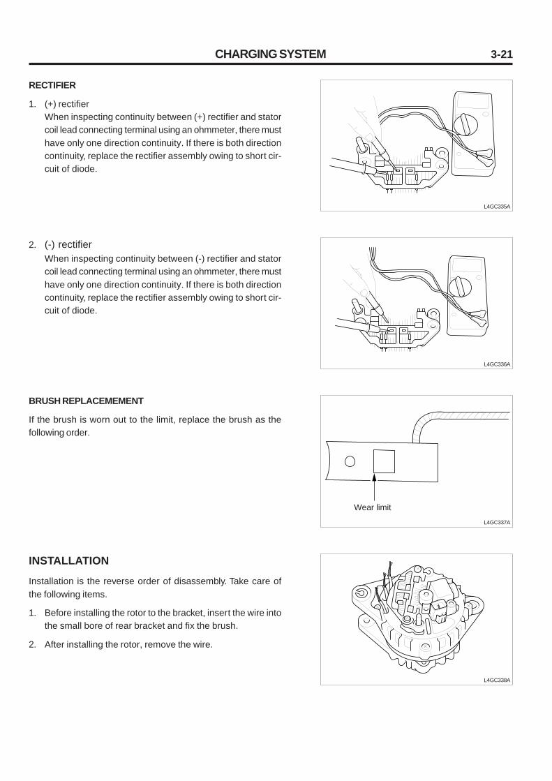
3-21
RECTIFIER
1. (+) rectifierWhen inspecting continuity between (+) rectifier and statorcoil lead connecting terminal using an ohmmeter, there musthave only one direction continuity. If there is both directioncontinuity, replace the rectifier assembly owing to short cir-cuit of diode.
L4GC335A
L4GC336A
L4GC337A
L4GC338A
2. (-) rectifierWhen inspecting continuity between (-) rectifier and statorcoil lead connecting terminal using an ohmmeter, there musthave only one direction continuity. If there is both directioncontinuity, replace the rectifier assembly owing to short cir-cuit of diode.
BRUSH REPLACEMEMENT
If the brush is worn out to the limit, replace the brush as thefollowing order.
INSTALLATION
Installation is the reverse order of disassembly. Take care ofthe following items.
1. Before installing the rotor to the bracket, insert the wire intothe small bore of rear bracket and fix the brush.
2. After installing the rotor, remove the wire.
CHARGING SYSTEM
Wear limit

3-22
L4GC339A
INSTALLATION
1. After placing the alternator, insert the support bolt. (At thistime do not insert the nut.)
2. After pressing forward the alternator, Contact the alternatorfront bracket with front case (A) as shown in the illustration.
3. Insert and install the nut by tightening it to the specifiedtorque.
CHARGING SYSTEM
Alternator
Nut
A
Support bolt
Front case
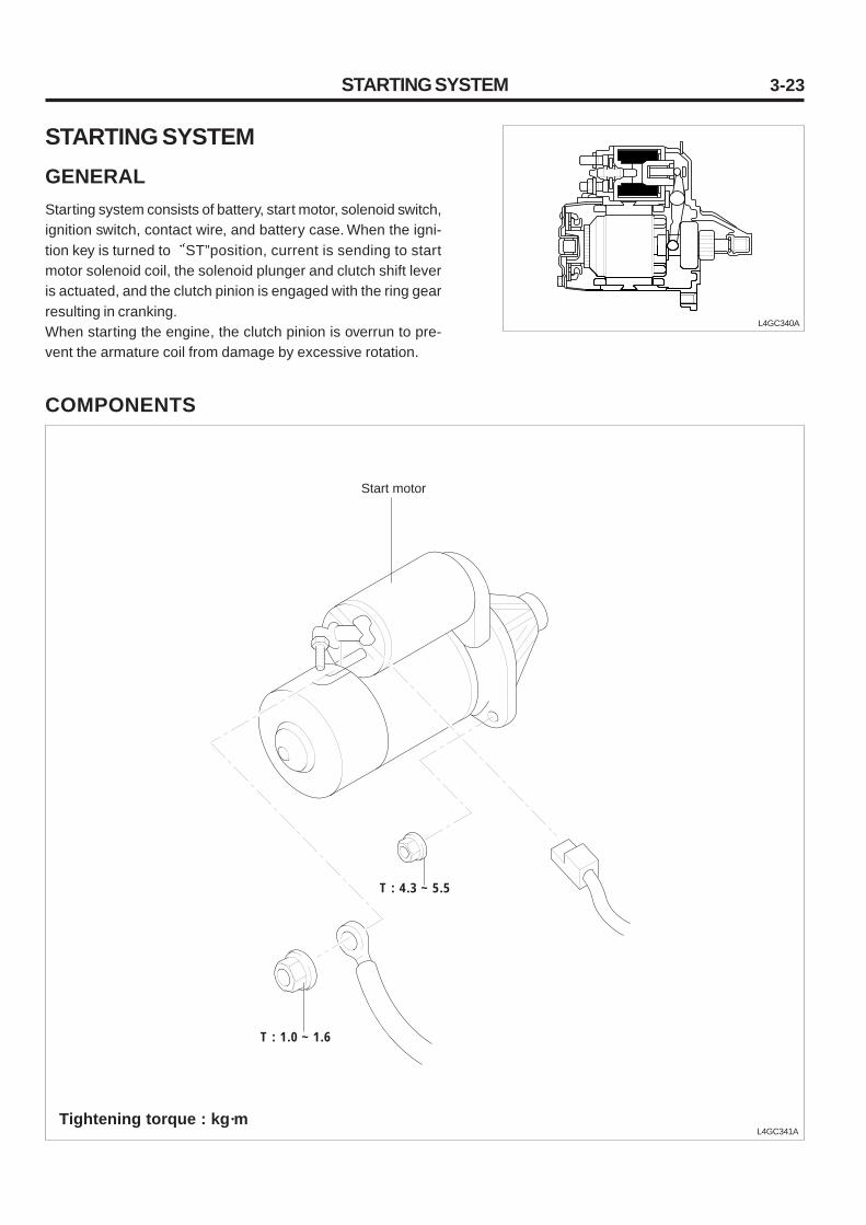
3-23STARTING SYSTEM
STARTING SYSTEMGENERALStarting system consists of battery, start motor, solenoid switch,ignition switch, contact wire, and battery case. When the igni-tion key is turned to ST”position, current is sending to startmotor solenoid coil, the solenoid plunger and clutch shift leveris actuated, and the clutch pinion is engaged with the ring gearresulting in cranking.When starting the engine, the clutch pinion is overrun to pre-vent the armature coil from damage by excessive rotation.
L4GC340A
COMPONENTS
L4GC341ATightening torque : kg·m
Start motor
T : 4.3 ~ 5.5
T : 1.0 ~ 1.6

3-24
TROUBLESHOOTINGStarting system problem can be classified into Start motor isnot operating , Start motor is operating but engine is notstarting , and There is a lot of time taken to start engine .
When the starting system has problems, before removing thestart motor, find where the problem happens. Generally if it isdifficult to start, there are problems in ignition system, fuelsystem, and electrical system. In this case, necessarily in-spect and repair step by step, or the same problem will happen.
Symptom Remedy
Impossible cranking Low battery charging voltage
Loose, corroded or worn battery cable
Short circuit of fusible link
Start motor fault
Ignition switch fault
Charge or replace
Repair or replace
Replace
Repair
Replace
Possible cause
Slow cranking Low battery charging voltage
Loose, corroded or worn battery cable
Start motor fault
Charge or replace
Repair or replace
Repair
Continuous rotating of startmotor
Start motor fault
Ignition switch fault
Repair
Replace
Start motor is rotating butengine is not cranking
Short circuit of wiring
Worn or broken pinion gear tooth or motor fault
Worn or broken ring gear tooth
Repair
Repair
START MOTORREMOVAL AND INSTALLATION
1. Disconnect the battery ground cable.
2. Separate the start motor connector and terminal.
3. Remove the start motor assembly.
4. Installation is the reverse of removal.
STARTING SYSTEM
Replace flywheel ring gear

3-25
COMPONENTS
L4GC343A
1. Screw2. Front bracket3. Snap ring4. Stop ring5. Overrunning clutch
6. Lever7. Plate8. Packing B9. Shim10. Internal gear
11. Magnetic switch12. Planetary gear holder13. Planetary gear14. Ball15. Packing A
16. Yoke assembly17. Armature18. Brush holder19. Through bolt20. Rear bracket
STARTING SYSTEM
1
23
4
5
9
10
11
12
13
14
6
7
8
15
16
17
18
19
20
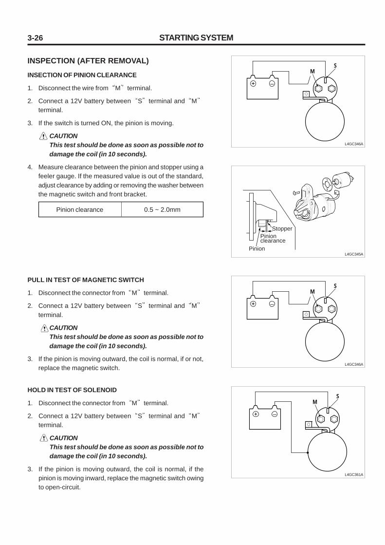
3-26
INSPECTION (AFTER REMOVAL)
INSECTION OF PINION CLEARANCE
1. Disconnect the wire from M terminal.
2. Connect a 12V battery between S terminal and Mterminal.
3. If the switch is turned ON, the pinion is moving.
CAUTIONThis test should be done as soon as possible not todamage the coil (in 10 seconds).
4. Measure clearance between the pinion and stopper using afeeler gauge. If the measured value is out of the standard,adjust clearance by adding or removing the washer betweenthe magnetic switch and front bracket.
PULL IN TEST OF MAGNETIC SWITCH
1. Disconnect the connector from M terminal.
2. Connect a 12V battery between S terminal and Mterminal.
CAUTIONThis test should be done as soon as possible not todamage the coil (in 10 seconds).
3. If the pinion is moving outward, the coil is normal, if or not,replace the magnetic switch.
HOLD IN TEST OF SOLENOID
1. Disconnect the connector from M terminal.
2. Connect a 12V battery between S terminal and Mterminal.
CAUTIONThis test should be done as soon as possible not todamage the coil (in 10 seconds).
3. If the pinion is moving outward, the coil is normal, if thepinion is moving inward, replace the magnetic switch owingto open-circuit.
STARTING SYSTEM
L4GC345A
Pinion clearance 0.5 ~ 2.0mm
SM
L4GC346A
SM
L4GC361A
Pinion clearance
Pinion
Stopper
SM
L4GC346A

3-27
RETURN TEST OF SOLENOID
1. Connect the connector from M terminal.
2. Connect a 12V battery between S terminal and Mterminal.
CAUTIONThis test should be done as soon as possible not todamage the coil (in 10 seconds).
3. When releasing after pulling the pinion outward, if the pinionis returned to native position, it is normal, if or not, replacethe solenoid valve.
STARTING SYSTEM
PERFORMANCE TEST (WITH NO-LOAD)
1. Connect a 12V battery to the start motor.
2. To operate the start motor with no load, turn the switch ON.If the operating speed and current measured are identifiedwith the standard, the start motor is normal. If the operatingspeed is insufficient or the current is excessive, it is be-cause of excessive friction resistance. And the low currentor lack of operating speed is because of faulty contact oropen circuit between the brush and the rectifier or betweenthe welding points.
DISASSEMBLY
To remove the overrunning clutch from the armature shaft, re-move the stop ring. Remove the stop ring by moving it to thepinion side, and then remove the stop ring from the shaft.
L4GC347A
L4GC342A
L4GC349A
Speed
Current
Minimum 3,000rpm
Maximum 60A or less
INSPECTION (AFTER DISASSEMBLY)
1. GROUND TEST OF ARMATURE COILCheck continuity between the commutator and the arma-ture coil using a circuit tester. If there is continuity, replacethe rotor assembly.
SM
L4GC362A
Armature
Start motor
Voltmeter
Battery12V
Switch
Carbon pile rheostat
Snap ring
Stop ring

3-28
2. SHORT CIRCUIT TEST OF AMARTURE COILInspect the armature coil in the growler and if there is shortcircuit, replace the coil. During core rotation, if the bladeattached in the core is vibrated, the armature is short.
3. OPEN CIRCUIT TEST OF ARMATURE COILCheck continuity between the commutator segments usinga circuit tester. If there is no continuity, replace the arma-ture assembly owing to open circuit of commutator segment.
4. OPEN CIRCUIT TEST OF FIELD COILCheck continuity of the field coil using a circuit tester. Ifthere is no continuity, replace the field coil assembly owingto open circuit of the field coil.
L4GC350A
L4GC351A
L4GC352A
5. GROUND TEST OF FIELD COILWith the yoke field coil installed, inspect continuity betweenthe field coil and the yoke, if there is continuity, replace thefield coil.
L4GC353A
STARTING SYSTEM

3-29STARTING SYSTEM
L4GC355A
6. BRUSHIf the brush is worn out to the limit, replace the brush.
7. BRUSH HOLDERCheck continuity between the (+) side brush holder and thebase. If there is continuity, replace the brush holderassembly.
L4GC354A
9. BRUSH REPLACEMENT
1) Remove the worn brush taking care not to damage thepigtail.
2) For better welding, correct the pigtail end with a sandpaper.
3) Weld the pigtail end.
L4GC357A
L4GC356A
8. OVERRUNNING GLUTCH
1) Check the pinion and spline teeth for wear and damageand replace it if necessary. Also, inspect the flywheelfor wear and damage.
2) Rotate the pinion. The pinion must be rotated clockwisebut counterclockwise.
Wear limit
Lock
Loosen
Marked surface
Pigtail
Welding portion

3-30 STARTING SYSTEM
L4GC359A
10. INSTALLATION OF REAR BRACKET
1) Before removing the bushing, measure the bushingpress-fit depth.
2) Remove the bushing as shown in the illustration.3) Press-fit a new bushing as the depth measured proce-
dure 1).
ASSEMBLY
1. Install the overrunning clutch to the armature shaft frontend.
2. Install the stop ring and snap ring to the armature shaftfront end and completely press the stop ring toward thesnap ring.
3. When installing the lever to the front bracket, take care ofthe direction. If the installation direction is in reverse, thepinion will move outward only.
L4GC358A
L4GC360A
Overrunning clutch
Stop ring clutch
Stop ring
Snap ring

1. GENERAL ........................................................................ 4- 1
2. INJECTOR ....................................................................... 4- 14
4. PVC VALVE ...................................................................... 4- 16
CHAPTER 4. FULE SYSTEM AND OTHER

4-1
GENERAL
SPECIFICATIONS
Item Specification
Input sensor
Type
Type
Driving
Type
High pressure type
Tank built-in electric type
Electric motor
Piezo electric type
0.8-1.1V(at idle)
4.5-5V(opened)
Thermostat type
2.0 - 3.0 (at 20°C)
Thermostat type
3.4V (at 20°C)
2.7V (at 40°C)
Zirconia sensor (Heater built in type)
0 - approx. 1V
Hole effector type
0~5V
Magnetic type
IDLE rpm : 600 ~ 800Hz
3000 rpm : 2700 ~ 3300Hz
Electric-magnetic type
4
14.5 0.35 (20°C)
SEALANTS
Water temperature assembly LOCTITE 962T
Fuel filter
Fuel pump (Including fuel filter)
Map sensor
Intake temperature sensor
Output actuator
Item Specified sealant
GENERAL
Water temperature sensor
(WTS)
Oxygen sensor
Hole sensor(#1 TDC sensor)
Crankshaft position sensor
Injector
Type
Resistance
Type
Output voltage
Type
Resistance
Type
Output voltage
Type
Output voltage
Output frequency
Type
Number
Coil resistance

4-2
Item Specified value (kg·m)
TIGHTENING TORQUE
1.5 ~ 2.0
5.0 ~ 6.0
1.0 ~ 1.3
1.5 ~ 2.0
2.5 ~ 3.4
Water temperature sensor
Oxygen sensor
Fuel supply pipe mounting bolt
Throttle body mounting bolt
High pressure hose and pipe tightening
SPECIAL TOOLS
Fuel pressure gauge and hose(09353-24100)
Fuel pressure gauge adaptor(09353-38000)
Fuel pressure gauge connector(09353-24000)
Connection of fuel pressure gauge andfuel supply pipe
UseConfigurationSpecial tool
L4GC251A
L4GC250A
L4GC252A
GENERAL
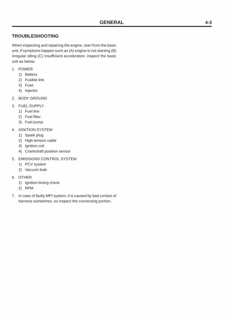
4-3
TROUBLESHOOTING
When inspecting and repairing the engine, start from the basicunit. If symptoms happen such as (A) engine is not starting (B)irregular idling (C) insufficient acceleration, inspect the basicunit as below.
1. POWER1) Battery2) Fusible link3) Fuse4) Injector
2. BODY GROUND
3. FUEL SUPPLY1) Fuel line2) Fuel filter3) Fuel pump
4. IGNITION SYSTEM1) Spark plug2) High tension cable3) Ignition coil4) Crankshaft position sensor
5. EMISSIONS CONTROL SYSTEM1) PCV system2) Vacuum leak
6. OTHER1) Ignition timing check2) RPM
7. In case of faulty MPI system, it is caused by bad contact ofharness sometimes, so inspect the connecting portion.
GENERAL
4-4
INSTRUCTION FOR MPI INSPECTION
1. When checking the alternator for charging, never removebattery (+) terminal.(If peak voltage of alternator is not absorbed by battery, itis possible to burn out ECU power terminal element.)
2. 1. When inspecting circuit, use a digital multi-meter or aLED of 1M or more.(When using normal valve, if heavy load current is sent toECU, it is possible to burn out driving TR.)
3. When disconnecting ECU harness, necessarily turn Igni-tion switch OFF.(It is possible to damage ECU element by surge.)
4. When removing battery terminal, turn Ignition switch OFF.(It is possible to damage ECU element by surge.)
5. When checking A/CON for operation, use a hi-scan andwhen from the outside (relay driving source), use its har-ness tool.(It is possible to burn out ECU.)
6. When welding vehicle body, necessarily remove ECU first.(It is possible to damage ECU element by surge.)
7. When charging battery from outside charger, remove bat-tery (vehicle side) terminal.(If supply voltage exceeds rated voltage of EUC, It is pos-sible to burn out ECU.)
8. When charging battery or starting engine with outside charg-ing power, never use it of 16V or more.(If supply voltage exceeds rated voltage of EUC, It is pos-sible to burn out ECU.)
9. For circuit test, do not use sensor ground as earth.(If heavy load current is run to sensor ground, It is possibleto burn out PCB ground circuit.)
GENERAL
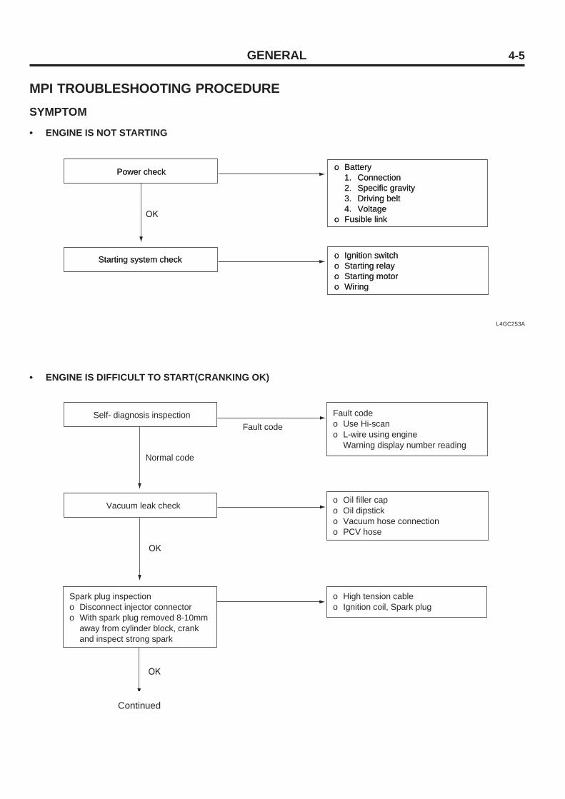
4-5
MPI TROUBLESHOOTING PROCEDURESYMPTOM
• ENGINE IS NOT STARTING
L4GC253A
• ENGINE IS DIFFICULT TO START(CRANKING OK)
Continued
GENERAL
Power checkPower check
Starting system checkStarting system check
o Battery1. Connection 2. Specific gravity3. Driving belt4. Voltage
o Fusible link
o Battery1. Connection 2. Specific gravity3. Driving belt4. Voltage
o Fusible link
o Ignition switcho Starting relayo Starting motoro Wiring
o Ignition switcho Starting relayo Starting motoro Wiring
Self- diagnosis inspection
Vacuum leak check
Spark plug inspectiono Disconnect injector connectoro With spark plug removed 8-10mm
away from cylinder block, crank and inspect strong spark
Fault codeo Use Hi-scano L-wire using engine
Warning display number reading
o Oil filler capo Oil dipsticko Vacuum hose connectiono PCV hose
o High tension cableo Ignition coil, Spark plug
Normal code
Fault code

4-6
L4GC254A
• IRREGULAR IDLING OR ENGINE IS SUDDENLY STOPPED
GENERAL
Continued
Self- diagnosis inspection
Fuel supply to injector check o Fuel in tanko Fuel pressure
Air cleaner element inspection
Fault codeo Use Hi-scanWarning display number reading
o Fuel line (Leak, Deformation)o Fuel pumpo Fuel filtero Fuel pressure regulator
Clean or replace element
Vacuum leak check o Oil filler capo Oil dipsticko Vacuum hose connectiono PCV hose
Ignition plug inspectionStandard: 0.7-0.8mm o Inspect compression if necessary
Ignition timing inspection
Fuel supply to injector check o Fuel in tanko Fuel pressure
o Fuel line (Leak, Deformation) o Fuel pumpo Fuel filtero Fuel pressure regulatoro Regulator (-) pressure check
o Wiring connectiono ECU power
1. Fusible link2. Fuse3. MPI main relay
o Engine cooling temperature sensoro Intake temperature sensoro Injection signal circuit
1. Injector wiring2. ECU
o Throttle position sensor (TPS)o MAP sensoro Crankshaft position sensorMPI electronic circuit inspection

4-7
L4GC255A
• ENGINE HESITATION OR INSUFFIENT ACCELELATION
GENERAL
Continued
Clean or replace element Air cleaner element inspection
o Oil tilt capo Oil dipsticko Hose connectiono PCV hose
Vacuum leak inspection in Intake line
Spark plug inspectionStandard: 0.7-0.8mm o Inspect compression if necessaryo CompressionStandard: 15.5-16.5 kg/cm
(50 - 400 rpm)
Fuel pressure inspection
Injector inspection
MPI electronic circuit inspection
RPM inspection
Compression inspection
o Fuel pumpo Fuel filtero Fuel pressure regulatoro Regulator (-) pressure check
Injector condition
Ignition timing inspection o Wiring connectiono ECU power
1. Fusible link2. Fuse3. MPI main relay
o Engine cooling temperature sensoro MAP sensoro Injection signal circuit
1. Injector wiring2. ECU
ISA inspection
Not OK

4-8
L4GC256A
GENERAL
o Wiring connectiono ECU power
1. Fusible link2. Fuse3. MPI main relay
o Engine cooling temperature sensoro Intake temperature sensoro Injection signal circuit
1. Injector wiring2. ECU3. Crankshaft position sensor4. Camshaft position sensor5. Catalyst melting6. Emission system clogged7. Throttle position sensor (TPS)8. MAP sensor
Fault codeo Use Hi-scanWarning display number reading
Injector condition
Injector condition
o Fuel pumpo Fuel filtero Fuel pressure regulator
Self-diagnosis inspection
Spark plug inspectionStandard: 0.7-0.8mm o Inspect compression if necessaryo CompressionStandard : 15.5-16.5kg/cm
(50 - 400 rpm)
Ignition timing inspectionBTDC 2 5 /700rpm
Fuel system inspection Spark plug inspectiono Disconnect injector connectoro With spark plug removed 8-10mm
away from cylinder block, crank and inspect strong spark
Injector inspection
Fuel pressure inspection
MPI electronic circuit inspection

4-9
TROUBLESHOOTING GUIDE• The following number represents inspection order.
Starter relay
Not cranking
Starter is rotating but not cranking
Incomplete combustion
Increasingly cranking
Normally difficult to start
Difficult to start when cold
Difficult to start when hot
Incorrect initial idling
Low RPM
Irregular idling
Engine hesitation or deceleration
After starting, engine stops soon
Item
1
Sub symptom
Starter
Flywheel
Airflow
sensor circuit
Fuel pressure regulator
Water tem
perature sensor
Com
pression
Piston ring
Ignition timing
Timing belt
Injector
ECU
A/C
circuit
Connecting rod bearing
Fuel chamber
Crankshaft bearing
Main sym
ptomStarting
Faulty idlingEngine stops
Other
2
1
1
2
1
2
9
4
5
1
1
11
2
4
4
4
4
8
2
3
3
3
1
1
1
1
5
6
10
4
7
7
3
6
5
8
8
7
6
9
10
11
8
7
11
8
12
7
7
4
3
12
12
7
5
9
9
13
8
8
5
4
14
13
8
6
2
2
14
2
3
1
12
3 4
1
1
2
2
1
1
1
5
GENERAL
After depressing accelerationpedal, engine stops
After releasing acceleration pedal,engine stops
With A/C ON, engine stops
Fuel over-consumption

4-10
Crankshaft position sensor
Not cranking
Starter is rotating but not cranking
Incomplete combustion
Increasingly cranking
Normally difficult to start
Difficult to start when cold
Difficult to start when hot
Incorrect initial idling
Low RPM
Irregular idling
Engine hesitation or deceleration
After starting, engine stops soon
After depressing acceleration pedal, engine stops
After releasing acceleration pedal, engine stops
With A/C ON, engine stops
Fuel over-consumption
Item
Sub symptom
Spark plug
Fuel pump
Fuel line
Ignition circuit
Intake temperature sensor circuit
Cylinder head
Oxygen sensor circuit
Fuel leak
Main sym
ptomStarting
Faulty idlingEngine stops
3
2
3
2
2
4
5
5
5
5
9
3
6
6
6
6
10
4
4
10
13
13
11
3
3
2
2
6
2
15
3
7
Other
1 2
1
3 4 5
2
6 7 8 9 10 11 12
3
Other
Engine is overheated
Engine is supercooled
Coolant leak
Cooling pan
Cooling pan sw
itch
Radiator and radiator cap
Thermostat
Timing belt
Water pum
p
Spark plug
Oil pum
p
Cylinder head
Cylinder block
Coolant tem
perature gauge
GENERAL
Item
Sub symptom
Main sym
ptom

4-11
Item Detail
Criterion • When oxygen sensor voltage is 1.4V or more• With air fuel ratio in closed loop control
- When oxygen sensor voltage is 0.048 or less for 27 seconds- Except idling (more than certain rpm and negative pressure), when cooling
temperature is 15°C and in case of 0.348V < oxygen sensor voltage < 0.498Vfor 27 seconds
Troubleshooting
1. Mixture adaptation control forbidden• Fix it as final value
2. Air fuel ratio in closed loop control[NOTE]By minimum to maximum value difference of oxygen sensor, injection fuel quan-tity can be different up to 35%
Check lamp
Faulty sensor manage-ment
SENSOR CHARACTERISTICS• OXYGEN SENSOR
Oxygen sensor/ Related circuit1. Display oxygen sensor related circuit fault2. Inspect bad connection of connector, faulty wiring3. Check oxygen sensor for ground
- Measure voltage between sensor body and engine ground :If measured value is 20mv or less, inspect oxygen sensor parts.If measured value is 20mv or more, clean sensor mounting part.
4. At sensor output function, inspect oxygen sensor
If fault code is detected, turned ON
HI-SCAN • Possible to check fault• Possible to check oxygen sensor voltage
GENERAL
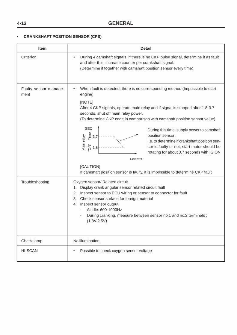
4-12
Item Detail
Criterion • During 4 camshaft signals, if there is no CKP pulse signal, determine it as faultand after this, increase counter per crankshaft signal.(Determine it together with camshaft position sensor every time)
Troubleshooting
• When fault is detected, there is no corresponding method (Impossible to startengine)
[NOTE]After 4 CKP signals, operate main relay and if signal is stopped after 1.8-3.7seconds, shut off main relay power.(To determine CKP code in comparison with camshaft position sensor value)
Check lamp
Faulty sensor manage-ment
• CRANKSHAFT POSITION SENSOR (CPS)
Oxygen sensor/ Related circuit1. Display crank angular sensor related circuit fault2. Inspect sensor to ECU wiring or sensor to connector for fault3. Check sensor surface for foreign material4. Inspect sensor output.
- At idle: 600-1000Hz- During cranking, measure between sensor no.1 and no.2 terminals :
(1.8V-2.5V)
No illumination
HI-SCAN • Possible to check oxygen sensor voltage
During this time, supply power to camshaftposition sensor.I.e. to determine if crankshaft position sen-sor is faulty or not, start motor should berotating for about 3.7 seconds with IG ON
[CAUTION]If camshaft position sensor is faulty, it is impossible to determine CKP fault
L4GC257A
GENERAL
SEC
Mai
n re
lay
"ON
"T
ime
3.7
1.8

4-13
Item Detail
Criterion • During 4 camshaft signals, there is nosignal changed at camshaft positionsensor
Troubleshooting
• Injection successive injection control
Check lamp
Faulty sensormanagement
• CAMSHAFT POSITION SENSOR (NO.1 TDC SENSOR), VEHICLE SPEED SENSOR
OFF at all times
HI-SCAN • Possible to check fault
Vehicle speed sensor
• When 400rpm or more, (-) pressure of574mb or more, and negative pressurelimit is less than 121mb, there is nosensor signal over 3 seconds
• Determine all as ON DRIVING[NOTE]Vehicle signal is used for ignition timing control. Assume proper gear bycalculating rpm, vehicle speed, andgear ratio backward. Control ignitiontiming to prevent impact whenrepressing throttle again afterreleasing.
No.1 cylinder TDC sensor/related circuit1. Display fault of cylinder TDC
detecting sensor (CMP sensor) andrelated circuit
2. Check connector for bad connectionand wiring for fault
3. Inspect sensor contact surface forcleanness
4. Inspect sensor output- At idle: 5-9Hz(0-5V)- 3000rpm : 20-30Hz(0-5V)
Vehicle speed sensor/Related circuit1. Display fault of vehicle speed sensor
related circuit2. Inspect bad connection of connector,
faulty wiring3. Inspect speedometer cable4. Inspect vehicle speed sensor- With vehicle stopped : 0Hz
While driving at about 300km/h :20-30Hz
OFF at all times
• Possible to check fault
GENERAL
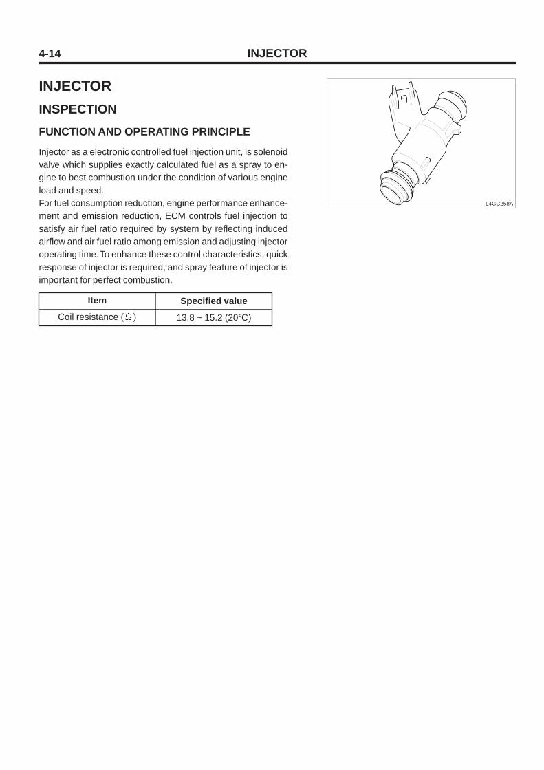
4-14 INJECTOR
INJECTORINSPECTIONFUNCTION AND OPERATING PRINCIPLE
Injector as a electronic controlled fuel injection unit, is solenoidvalve which supplies exactly calculated fuel as a spray to en-gine to best combustion under the condition of various engineload and speed.For fuel consumption reduction, engine performance enhance-ment and emission reduction, ECM controls fuel injection tosatisfy air fuel ratio required by system by reflecting inducedairflow and air fuel ratio among emission and adjusting injectoroperating time. To enhance these control characteristics, quickresponse of injector is required, and spray feature of injector isimportant for perfect combustion.
L4GC258A
Item
Coil resistance ( )
Specified value
13.8 ~ 15.2 (20°C)

4-15INJECTOR
PARTS INSPECTION
1. Turn the ignition switch OFF.
2. Disconnect the injector connector.
3. Measure resistance between injector terminal #1 and #2.
4. Check that the measured resistance is different from speci-fication (Refer to SPECIFICATIONS)
Specified value See SPECIFICATIONS
CIRCUIT DIAGRAM
L4GC259A
[CIRCUIT DIAGRAM] [CONNECTING INFORMATION]
[HARNESS CONNECTOR]
Injector #1 (CBG24-1)
Injector #2 (CBG24-2)
Injector #3 (CBG24-3)
Injector #4 (CBG24-4)
ECM (CBG-K)
2
1
1
2
1
2
1
2
Main relay
Injector #1 control
Injector #2 control
Injector #3 control
Injector #4 control
Main relay
Main relay
Main relay
2 1
25
28
26
27
CBG24-1,2,3,4Injector #1,2,3,4
Terminal
1
2
Connecting area
Main relay
ECM CBG-K (25)
Function
Power (B+)
Injector #1 control
INJECTOR #1 (CBG24-1)
Terminal
1
2
Connecting area
ECM CBG-K (28)
Main relay
Function
Injector #2 control
Power (B+)
INJECTOR #2 (CBG24-2)
Terminal
1
2
Connecting area
ECM CBG-K (26)
Main relay
Function
Injector #3 control
Power (B+)
INJECTOR #3 (CBG24-3)
Terminal
1
2
Connecting area
ECM CBG-K (27)
Main relay
Function
Injector #4 control
Power (B+)
INJECTOR #4 (CBG24-4)

4-16
Intake Manifold Side (No Vacuum)
PCV VALVEOUTLINE AND OPERATING PRINCIPLE
PCV VALVE
Intake Manifold Side (High Vacuum)
Engine condition
PCV valve
Vacuum path
No operating
No operating
Clogged
Locker Cover Side Locker Cover Side
Engine condition
PCV valve
Vacuum path
At idle or deceleration
Full operating
Small
Intake Manifold Side (Sufficient Vacuum) Intake Manifold Side (Low Vacuum)
Engine condition
PCV valve
Vacuum path
Proper operating
Proper operating
Big
Locker Cover Side Locker Cover Side
Engine condition
PCV valve
Vacuum path
High speed and overload
Light operating
Very big
L4GC260A L4GC261A
L4GC262A L4GC263A

4-17
SERVIE PROCEDUREREMOVAL
1. After disconnecting the vacuum hose(A), remove the PCVvalve(B).
L4GC265A
PCV VALVE
INSTALLATION
Install the PCV valve and connect the vacuum hose.
Tightening torque 0.8 ~ 1.2kgf·m
INSPECTION
1. Remove the PCV valve.
2. Check the plunger for movement by inserting a thin stick(A) toward the valve (B) nut.
3. If the plunger is not moved, it means that PCV valve isclogging, so, clean or replace PCV valve.
TROUBLESHOOTING
1. Disconnect the vacuum hose from the PCV valve. Discon-nect the PCV valve from the locker cover and reconnectthe vacuum hose.
2. With the engine at idle, Check the intake manifold forvacuum when clogging the opened end of PCV valve.
NOTEThe plunger in PCV valve will move back and forth.
3. If vacuum is not detected, clean or replace PCV valve andvacuum hose.
BA
L4GC266A
B
A
L4GC264A