i 4803 load analysis on tall tile silos removal … · 4803 wind load analysis on tall tile silos i...
TRANSCRIPT
4803
WIND LOAD ANALYSIS ON TALL TILE SILOS I
WITH REMOVAL OF CONNECTING PLATFORM PLANT 1 ORE SILOS OPERABLE UNIT 3 REMOVAL ACTION 13 SEPTEMBER 1993 REVISION 0
09/30/93
FERIMCO/DOE-FN 1.5 REPORT
~I I I
Wind Load Analysis on Tall Tile Silos with Removai of Connecting Platform
Plant I Ore,Siios
Operable Unit 3 Project Order 22 September 1993
Revision 0
Environmental Remedial Action Project Fernald Environmental Management Project
Fernald, 0 hio FERMCO Subcontract No. 2-21487
[EJ PARSONS
Fairfield Executive Center 6120 South Gilmore Road
Fairfield, Ohio 45014
. - I , , ,
,
Wind Load Analysis on Tall Tile Silos with Removal of Connecting Platform
Plant 1 Ore Silos
CONTENTS
. . . . . . . . . . . . . . . . . . . . . . . . . . . . . . . . . . . . . . . . . . . . . . . . . Executive Summary E- 1
SECTION
. . . . . . . . . . . . . . . . . . . . . . . . . . . . . . . . . . . . . . . . . . 1.0 Statement of Problem 1-1.
. . . . . . . . . . . . . . . . . . . . . . . . . . . . . . . . . . . . . . . . . . . . 2.0 Anaiysis Approach 2- 1
3.0 Key Assumptions and Limitations . . . . . . . . . . . . . . . . . . . . . . . . . . . . . . . . . . 3- I
. . . . . . . . . . . . . . . . . . . . . . . . . . . . . . . . . . . . 4.0 Discussion of Analysis Results 4- 1
5- 1 . . . . . . . . . . . . . . . . . . . . . . . . . . . . . . . . . . . . . . . . . 5.0 S ~ o f - R e s d t s . .
. . . . . . . . . . . . . . . . . . . . . . . . . . . . . . . . . 6.0 Conclusions and Recommendations 6- 1
7 - 1 7.0 References . . . . . . . . . . . . . . . . . . . . . . . . . . . . . . . . . . . . . . . . . . . . . . . . .
APPENDICES
A Calculations
i? . : : . . . .
. . . . -
.. - -
I '
. ERAFSI\VOLl :RSAPPS\RSDATA\ OU-3\PO-22\WINDLOAD
, :;I, . Rev. No.: 0 - I -
LIST OF ACRONYMS AND ABBREVIATIONS
ASCE FEMP mPh psi
American Society of Civil Engineers Fernald Environmental Management Project miles per hour pounds per square inch
ERAFS l\VOLI :RSAPPS\RSDATA\ OU-3\PO-22\WINDLOAD
0003 Rev. No.: 0
.. , '>, ,
EXECUTtVE SUMMARY
The Plant 1 Ore Silos consist of six 10-foot-tall concrete silos, four IO-foot-tall tile silos. and four 44-
foot-tall tile silos. A11 of the silos and supporting structures exhibit varying signs of degradation. The tall tile silos, especially the southwestern tile silo (F2-26), exhibit severe degradation (e.g., spalled tiles. missing mortar joints, etc.). In addition, there is concern that the removal of the access platform connected to the concrete caps of each of the tall tile silos will have a detrimental effect on the stability of the tall tile silos.
The tall tile silos were evaluated for load cases considering the complete removal of the platform and equipment with and without a concrete cap. The load case of complete removal of equipment with a portion of the piatform and concrete cap remaining was also evaluated. Failure modes considered include overturning due to toppling as an in-tact unit. failure due to cracking induced by tensile stress. and.failure due to cracking or crushing caused by excessive compressive stress. In addition. factors such as material degradation and leaning were considered. Critical assumptions made in lieu of actual material testing include zero tensile strength in the mortar, a reduction of 10 to 20 percent in mortar joint bearing area. and a reduction of 25 to 50 percent in the allowable compressive strength of the mortar.
Based on the results of this analysis, PARSONS recommends that the connecting access platform be removed immediately. The platform is not required for stability. and its removal will decrease the overturning wind load and compressive stresses. The silos will then resist an 80 mile per hour (mph) wind speed in a freestanding condition. even when taking into account factors such as material degradation and leaning. Immediate removal of the cap is not necessary since this would have little effect on the silo overturning stakility or compressive stresses. Due to uncertainties concerning material integrity and strength, consideration of partial erection of the scaffolding and containment sheeting for shielding is recommended. so long as their erection does not hinder the immediate removal of the access platform. This may involve a change in priorities in the dismantlement sequencing.
' :I n 4 , * ; / j ; i ERAFSI\VOLl :RSAPPSU\SDATA\ OU-3\PO-22\WINDLOAD E- 1 Rev. No.: 0

SECTION 1
- -
I
STATEMENT OF PROBLEM
The 44-foot-tall tile silos were evaluated for the overturning forces of wind load. assuming that the top connecting platform between the tall silos is removed. This condition would leave freestanding silos supported by the steel framing below without interconnection at the top of the silos.
Three load cases for the tall tile silos were considered:
1) Case 1: All equipment and platform framing removed from the top of each silo. including the concrete caps.
' 2) Case 2: All equipment and platform framing removed from the top of each silo. excluding the concrete caps.
3) Case 3: All equipment and some of the platform framing removed from the top of the silos. but with that portion of the platform framing directly on top of the each silo remaining. attached to the concrete cap.
The calculated results for each of these three cases have been compared to each other. and also to the existing condition, with the entire top connecting platform in place.
I
W A F S 1 \VOLl :RSAPPS\RSDATA\ OU-3\PO-22\WINDLOAD 1-1
' I ! . . ! ' > \ C", ,
Rev. NO.: 0 . .
SECTION 2
ANALYSIS APPROACH
Wind loads were calculated based on the criteria of American Society of Civil Engineers (ASCE) 7-88, assuming Exposure C and an importance Factor of. 1 .O. For each case, the applicable force coefficients were applied to each structural component such as the silo walls, platform framing, and handrail.
m e critical section for'all cases was considered at the base of the silo wall, specifically at the bottom mortar joint, where both the maximum dead load and overturning stresses occur.
For each of the load cases defined in Section 1, three possible failure modes for the silos were considered:
1) Overturning Stability: Analysis of this failure mode assumed that a silo would remain as an in- tact unit until it toppled over from the high lateral wind loads. This unstable. overturning mode must be considered as the absolute upper limit for silo failure.
2) Zero Tensile Stress: Analysis of this failure mode assumed that the tile uni ts and joints may begin to exhibit severe cracking.if any portion of the masonry walls were to experience tension stress. The condition of tension cracking was considered as unacceptable. and therefore masonry stresses were limited to compression only.
3) Maximum Allowable Compressive Stress: Analysis of this failure mode assumed that compression cracking/crushing could begin if any portion of the masonry walls were to exceed the allowable compression stress. The actual design properties of the tile masonry were unknown: therefore. ultimate and allowable values were assumed. These values are based on published properties for similar tile masonry construction of approximately that date.
Consideration was given to the pccential effects of long-term exposure and degradation of the mortar joints. This degradation was considered as a combination of two possible factors (i.e.. partid loss of mortar in the joints and partial reduction of the compressive strength of the masonry wall. particularly of the mortar remaining in the joint). Consideration was also given to the eccentric overturning effect of an out-of-plumb (leaning) silo.
I .
ERAFSI\VOLI :RSAPPS\RSDATA\ OU-3\PO-22\WINDLOAD 2- 1 Rev. No.: 0
. . ,' . 4
SECTION 3
KEY ASSUMPTIONS AND LIMITATIONS
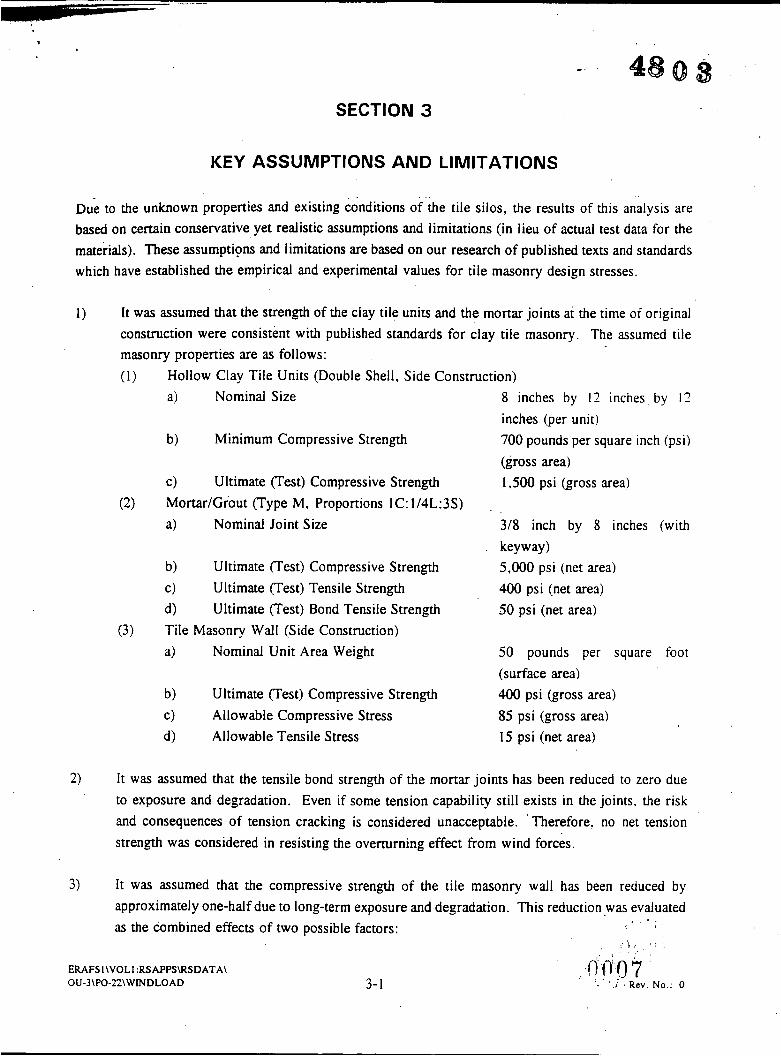
Due to the unknown properties and existing conditions of the tile silos, the results of this analysis are based on certain conservative yet realistic assumptions and limitations (in lieu of actual test data for the materials). These assumptions and limitations are based on our research of published texts and standards which have established the empirical and experimental values for tile masonry design stresses.
1) It was assumed that the strength of the clay tile units and the mortar joints at the time of original construction were consistent with published standards for clay tile masonry. The assumed tile masonry properties are as follows:
Hollow Clay Tile Units (Double Shell. Side Construction) a) Nominal Size 8 inches by 12 inches by 12
b) Minimum Compressive Strength 700 pounds per square inch (psi)
c) Ultimate (Test) Compressive Strength 1,500 psi (gross area) Mortar/Grout (Type M, Proportions IC: 1/4L:3S) a) Nominal Joint Size 318 inch by 8 inches (with
b) Ultimate (Test) Compressive Strength 5,000 psi (net area) c> Ultimate (Test) Tensile Strength 400 psi (net area) d) Ultimate (Test) Bond Tensile Strength 50 psi (net area) Tile Masonry Wall (Side Construction) a> Nominal Unit Area Weight 50 pounds per square foot
b) Ultimate (Test) Compressive Strength 400 psi (gross area) c) Allowable Compressive Stress 85 psi (gross area) d) Allowable Tensile Stress 15 psi (net area)
inches @er unit)
(gross area)
key way
(surface area)
2) It was assumed that the tensile bond strength of the mortar joints has been reduced to zero due to exposure and degradation. Even if some tension capability still exists in the joints. the risk and consequences of tension cracking is considered unacceptable. Therefore. no net tension strength was considered in resisting the overturning effect from wind forces.
3) It was assumed that the compressive strength of the tile masonry wall has been reduced by approximately one-half due to long-term exposure and degradation. This reduction .was evaluated as the combined effects of two possible factors:
,:.
A:, : . . fl'(-j0 . . : 1 .
'3 '.i ,Rev . No.: 0 I
ERAFSI\VOLI :RSAPPS\RSDATA\ OU-3\PO-22\WINDLOAD 3- 1
.
The first contributing factor is loss of mortar, which was assumed to range from 10 to 20 percent reduction in bearing area of the mortar joint. (A reduction in bearing area of 20 percent is roughly equivalent to the loss of the outer 1-112 inches of the mortar joint around the entire circumference of the silo wall.) The second contributing factor is a reduction in the compressive strength of the masonry wall, particularly in mortar strength, which was assumed to range from 25 to 50 percent reduction in the allowable compressive stress. '
3-2 Rev. No.: 0
SECTION 4
DISCUSSION OF ANALYSIS RESULTS
The calculated results of the wind load analysis consist of an evaluation of each of the possible failure modes (overturning stability, zero tensile stress, and maximum allowable compressive stress) for each of the load cases.
For the overturning stability condition, the critical wind velocity was determined to be the velocity at which the isolated, freestanding silo would become unstable and topple. The only resistance to the overturning was taken as the dead weight of the silo and the structural elements attached at the top. The overturning safety factor was also calculated for a wind speed of 80 mph, which is the design wind speed for the Fernald Environmental Management Project (FEMP) site. The required safety factor against Overturning failure is 1.5.
For the zero tensile stress condition, the critical wind velocity was determined to be the velocity at which the leeward face of the unreinforced silo wall just reached zero stress at the base. This condition is equivalent to the critical point at which the overturning tensilekompressive stress is exactly equal to the dead load compressive stress. Thus the maximum combined compressive stress is equal to twice the dead load compressive stress. This value was calculated for comparison with the allowable compressive stress of 85 psi. The zero tension safety factor for a wind speed of 80 mph was also calculated. The required safety factor against tension failure is 1 .O.
For the allowable compressive stress condition. the maximum combined compressive stress was calculated for a wind velocity of 80 mph. The resulting actual compressive stress was compared to the allowable compressive stress of 85 psi. The net difference between the actual and allowable compressive stresses represents the percentage of reserve stress capacity (i.e.. it represents the percentage of reduction in allowable compressive strength due to degradation that can be assumed). (It should be noted that the allowable compressive stress of 85 psi is approximately one-fifth of the average ultimate compressive strength of 400 psi determined from actual tests.)
The effect of reducing the overall strength of the masonry to account for the loss of mortar (,due to degradation) was also considered for this condition. This reduction has no effect on the critical wind speeds for the overturning or zero tensile stress conditions. The resulting compressive stresses were calculated for the cases of 10 and 20 percent area reduction (or 90 percent and 80 percent bearing area. respectively) and compared to the allowable compressive stress of 85 psi.
ERAFS l\VOLl :RSAPPSWSDATA\ OU-3\PO-22\ WMDLOAD 4- 1 Rev. No.: 0

. .
: \
&=e 1 R ~ U I ~ S (without concrete caol
The critical wind velocity for overturning stability was determined to be 145 mph, with a safety factor against overturning of 3.3 for an 80 mph wind speed.
The critical wind speed for zero tension was calculated to be 98 mph, with a correspondin2 maximum compressive stress of 46 psi and an 80 mph safety factor of 1.5.
The maximum compressive stress (full area) for an 80 mph wind speed was computed to be 38 psi. with the maximum stress (90 percent area) of 42 psi and maximum stress (80 percent area) of 48 psi. Therefore, the resulting reduction in allowable compressive strength could range from 44 to 55 percent.
Case 2 Results (with concrete cap)-.-.. . .
The critical wind velocity for overturning stability was determined to be 155 mph. with a satetv tactor against overturning of 3.7 for an 80 mph wind speed.
The critical wind speed for zero tension was calculated to be 104 mph. with a corresponding maximum compressive stress of 52 psi and an 80 mph safety factor of 1.7.
The maximum compressive stress (full area) for an 80 mph wind speed was computed to be 41 psi. with the maximurn stress (90 percent area) of 46 psi and maximum stress (80 percent area) of 51 psi. Therefore, the resulting reduction in allowable compressive strength could range from 39 to 52 percent.
Case 3 Results (with concrete cao and oanial DlatformZ
The critical wind velocity for overturning stability was determined to be 132 mph. with a safetv factor against overturning of 2.7 for an 80 mph wind speed.
The critical wind speed for zero tension was calculated to be 88 mph, with a corresponding maximum compressive stress of 54 psi and an 80 mph safety factor of 1.2.
The maximum compressive stress (full area) for an 80 mph wind speed was computed to be 49 psi. with the maximum stress (90 percent ,area) of 55 psi and maximum stress (80 percent area) of 61 psi. Therefore, the resulting reduction in allowable compressive strength could range from 28 to 42 percent.
ERAFSI\VOLl :RSAPPS\RSDATA\ OU-3\PO-22\WINDLOAD 4-2 Rev. No.: 0
Previous Calculation Results (with existing full Dlatform)
We also reviewed the calculations performed previously by PARSONS for the existing condition. which were calculated with all of the platform frame in place for a 90 mph wind velocity. These calculations were prepared for the structural evaluation contained in the Removal Action 13 Work Plan. Adjustments were made to the previous results to account for the change in design wind velocity from 90 mph to 80 mph. The adjusted results are summarized here for comparison to the load cases described above.
The critical wind velocity for overturning stability was determined to be 115 mph. with a safety factor against overturning of 2.1 for an 80 mph wind speed.
The critical wind speed for zero tension was calculated to be 77 mph, with an 80 mph safety factor of 0.9 (which is less than the required 1.0).
The maximum compressive stress (full area) for an 80 mph wind speed was computed to be 58 psi. with the maximum stress (90 percent area) of 65 psi and maximum stress (80 percent area) of 72 psi. Also, a net tensile stress (full area) of 2.5 psi is developed for this scenario. Therefore. tension stress will occur at 80 mph wind speed and there is little resulting reduction in compressive strength available for this condition since the actual stress approaches the allowable compressive stress.
Allowance for Out-of-Plumb Silo
The effect of additional overturning and compressive stresses was also considered for the possibility of an out-of-plumb silo. Assuming that the overturning due to wind was in the same direction as the dead load eccentricity, an increase in overturning moment and compressive stresses would apply to all of the load cases. The magnitude of this effect was determined to be approximately 5 to 7 percent for an assumed out-of-plumb eccentricity of about 3 inches at the top of the silo.
ERAFS l\VOLl :RSAPPS\RSDATA\ OU-3\P0-22\ WtNDLOAD 4-3 R f7 1_ 1. Rev. No.: 0

SECTION 5
SUMMARY OF RESULTS
m e results of stability and strength calculations are summarized in the following table:
Description
1) Overturning Stability A. Critical Wind Speed. B. C. Required Safety Factor
Safety Factor @ V = 80 mph
2) Zero Tension Stress A. Critical Wind Speed B. Maximum Compressive Stress C. Safety Factor @ V = 80 mph D. Required Safety Factor
3) For 80 mph Wind Speed A. Maximum Compressive Stress
B. (90%) Compressive Stress
C. (80%) Compressive Stress
D. Allowable Compressive Stress
(Percent Reserve)
(Percent Reserve)
(Percent Reserve)
Case 1 (without
Concrete Cap)
145 mph 3.3 I .5
98 rnph 46 psi
1.5 1 .o
38 psi (55 %)
. 42 psi (51 %)
48 psi
(44%) 85 psi
Case 2 (with Concrete
Cap)
155 mph 3.7 I .5
104 mph 52 psi
1.7 1 .o
41 psi (52 % ) 46 psi (46%) 51 psi (39 %)
85 psi
Case 3 (with Partial
Platform)
132 rnph 2.7 I .5
88 rnph 54 psi
1.2 1 .o
49 psi (42%) 55 psi (36%) 61 psi (28%) 85 psi
The ranges of results and several trends can be observed from this table.
1) The wind speeds necessary to induce overturning instability (132 to 155 mph) are far in excess of the code-required wind velocity of 80 rnph for the FEMP site. Thus. overturning stability is not a problem for any of the load cases.
2) The wind speeds required to produce the zero tensile stress condition (88 to 104 rnph) are all greater than the design wind velocity of 80 mph. Thus, the silos will remain entirely in
' . ERAFS 1 \VOLl :RSAPPS\RSDATA\ OU-3\PO-22\WINDLOAD 5- 1 Rev. No.: 0
3) The compressive stresses resulting from the design wind speed of 80 mph are all less'&an the allowable compressive strength, even when accounting for a 20 percent loss in mortar. The resulting percentage reduction (28 to 55 percent) in allowable compressive strength that can be assumed for degradation indicates a significant reserve capacity.
The removal of dead load from the top of the silos generally tends to increase the overturning stability and decrease the compressive strmses, which indicates that it is desirable to remove as much of the dead weight as possible. The effect of removing the concrete cap is relatively small. whereas the effect of removing part of the platform framing is more significant.
The existing condition (with the full platform frame in place) is the worst condition. with net tension and high compressive stresses developing at the 80 mph wind speed. The lateral wind forces on this platform produce a greater increase in the'wind overturning moment when compared to the resisting moment developed by the dead weight of the platform.
4)
5)
~ s l \ v O L l :RSAPPS\RSDATA\
OU-3\PO-n\WINDLOAD Rev. No.: 0

SECTION 6
CONCLUSIONS AND RECOMMENDATIONS
This wind load analysis is based on conservative yet realistic assumptions regarding the unknown integrity md material strength of the tile silos in lieu of actual test data and measurements.
Based on these assumptions and the results of this wind load analysis. the following conclusions are made:
r 6 ' :.. .
.. .
1) The concrete cap and the connecting steel platform at the top of the tall tile silos can be removed without exceeding any of the failure criteria under an 80 mph design wind speed. even assuming
. . , . - I I I , - , . , a reduction in silo strength (.due to degraaatlon) Of about one-naIt ana eccentricity aue to a silo
being our of plumb.
2) The current situation. with the entire top connecting platform in place. represents the worst.
condition for ovemrnine caused by wind forces. The removal of additional weight and wind
projected area tends to increase the overturning stability and reduce the compressive stresses. .. . ? -\. .
. .A- - 3) Removal of the concrete cap has a relatively small effect on overturning stability or compressive stresses.
Based on these conclusions, the following recommendatlons are made related to structural safety: p.. ,. .
5; . ,_ . 1) ''T F..
The entire top connecting platform should be removed from the top of the silos immediately. At
the very least. the platform should be removed to the edge of each silo.
It is not necessarv to remove the concrete cap. since this has relatively little effecc on overturning
stability or compressive stresses.
Consideration should be given to Dartiallv erecting the scaffolding and containment sheeting as
... k, b Gj-, 2) hi, :*? . ~ ... . \ . -..?.. . ...
I./ ..
3) Soon as possible to provide wind shielding for the silos. This may involve a change in pr,iorities in the dismantlement sequencing. These steps are recommended as an additional safety Precaution based on h e unknowns concerning the integrity and strength of the silo material.
6- 1 Rev. No.: 0

(ASCE 1988)
(Butala 1993)
(Catalytic 1952)
(PARSONS 1992)
(Plummer 1962)
. . .
,0075
SECTION 7
REFERENCES
American Society of Civil Engineers, 1988. Minimum Design Loads for Buildings and Other Structures (Formerly ANSI A58.1). New York: ASCE. ASCE 7-88.
Butala, M.B., R.D. Flanagan, and R.M. Bennett, 1993. "Properties of Structural Clay Load-Bearing Wall Tile." Proceedings of The Sixth North American Masonry Conference. (June 6-9, 1993, Philadelphia) pp. 87-98.
Catalytic Construction Company, 1952. Specificorion for Feed Silos. Part IX, Section lB, Job #3002..
'
PARSONS 1992. Plant I Ore Silos Removal Action Number 13 Work Plan. Fairfield: PARSONS.
Plummer, H.C., 1962. Brickand 7ile Engineering. Reston. VA: Brick Institute of America.
ERAFS 1 \VOLl :RSAPPSUISDATA\ OU-3\PO-22\WINDLOAD 7- 1 Rev. No.: 0