i' 9 i-& h ., .. c t$;i;;;z: i, i,.,,;. ,, lj i -* '9 806 · 1970-02-20 · trw...
TRANSCRIPT
........... .......... ............ .......... * ......... h
..... ..... ..... a ..... ..... .....
I '
........... .......... ............ .......... ......... ......... ........... ........... ............ ........... ........... ............ ........... ............ ........... ............
.........I-& . * ........... .. I , . , , ; . ............ I , , , . , c
"ILm PAS$-01 806 ti! !,4;, i ; i i ,,
L J I T$;i;;;z: . i.;.;
9 - *
NATIONAL AERONAUTICS A N D SPACE ADMIN1STRA::lON
............ ........... ............ ........... .~.~.~.~.~.*.~.~.-.~.~. MSC INTERNAL NOTE NO. 70-FM-30
1 kfi 2 -; "IT3 February 20, 1970
.......... ........... ........... ........... ........... ........... ........... ........... ........... ........... ........... ........... ........... ...........
........... ........... ........... ........... ........... ........... ........... ........... APOLLO 11 ENTRY
POSTFLIGHT ANALYSIS
k :: .-.~.~.*.'.*.~.~ : .'.~.~.~.~.~.~.~.'.~.~ '.
.~.~.~.~.~.*.'.~.*.-.~ ............ ............ .......... .......... ........... ........... ........... ........... ........... ........... ........... ........... ........... ........... ........... :::: :: ::: ::
A-Tf4-X-69419) APOLLO 1 1 ENTRY N74-70902j PLIGHT ANALYSIS ( N A S A ) 38 p ..... ..... ..... .....
7' +. .
e
' 9 ' .
1 kkj 2 -; L - 3 February 20, 1970
..... ..... ..... ..... Unclas .... ..... ...... ..... . . . . . . . . . 00/99 16413 ............ ........... ............ ........... ........... ............ ........... ............ ........... ............ ........... ............ ........... ............ ........... ............ ........... ........ ............ ........... ............ ........... ............ ........... ............ ........... ............ ........... ............ ........... ............ ........... ............ ........... ............ ........... ............ ........... ............ ........... ............ ........... ............ ........... ............ ........... ............ ........... ............ ........... ............ ........... ............ ........... ............ ........... ............ ........... ............ ........... ............ ........... ............ ........... ............
............
...............
L A N D I N G ANALYSIS BRANCH MISSION P L A N N I N G A N D ANALYSIS D I V I S I O N
M A N N E D SPACECRAFT C E N T E R H 0 U STON ,TE X A S
I
I ........... ............ ........... ............ ........... ............ ........... ............ ........... ............ ........... ............ ........... ............ ........... ...........
................... ....
~ ............ ~1
J
-4*,, 4 *
MSC INTERNAL NOTE NO. 70-FM-30 1
P R O J E C T A P O L L O
A P O L L O 1 1 ENTRY P O S T F L I G H T A N A L Y S I S By R. Manders Guided Entry
TRW Systems Group
February 20, 1970
MISSION PLANNING A N D ANALYSIS DIVISION NATIONAL AERONAUTICS A N D SPACE ADMINISTRATION
MANNED SPACECRAFT CENTER HOUSTON, TEXAS
MSC Task Monitor D. Heath
.
I’
Floyd V. Bennett, Chief Landing Analysis Branch
Approved John PhAaver, Chief 0
I .
Mission1 Planning and Analysis Division r,

c
.
C . . e
'v .... * *. CONTENTS
S e c t i o n 1'
Page
1 . SUMMARY . . . . . . . . . . . . . . . . . . . . . . . . . . . . . . 1
2 . INTRODUCTION . . . . . . . . . . . . . . . . . . . . . . . . . . . 3
2.1 Purpose . . . . . . . . . . . . . . . . . . . . . . . . . . . 3
2.2 Genera l D e s c r i p t i o n o f Contents . . . . . . . . . . . . . . . 3
3 . ENTRY CONDITIONS . . . . . . . . . . . . . . . . . . . . . . . 5
4 . ENVIRONMENT RECONSTRUCTION . . . . . . . . . . . . . . . . . . . . 7
4 . 1 Ent ry Parameters . . . . . . . . . . . . . . . . . . . . . . . 7
5 . CMC EVALUATION . . . . . . . . . . . . . . . . . . . . . . . . . . 9
5.1 D e s c r i p t i o n of CMC Operat ion . . . . . . . . . . . . . . . . . 9
5.1.1 Ent ry I n i t i a l i z a t i o n and A t t i t u d e Hold (P63) . . . . . 9 5.1.2 Pos t 0.05g (P64) . . . . . . . . . . . . . . . . . . . 10 5.1.3 UPCONTROL Phase (P65) . . . . . . . . . . . . . . . . . 10 5.1.4 FINAL PHASE (P67) . . . . . . . . . . . . . . . . . . . 10
5.2 CMC S imula t ion . . . . . . . . . . . . . . . . . . . . . . . . 11
5.2.1 S imula t ion . . . . . . . . . . . . . . . . . . . . . . . 11 5.2.2 Comparison . . . . . . . . . . . . . . . . . . . . . . 11
5 . 3 EMS Recons t ruc t ion . . . . . . . . . . . . . . . . . . . . . . 12
6 . EVALUATION OF THE ENTRY OPERATIONS AND MONITORING PLAN . . . . . . 13
6.1 Ent ry Monitor ing P l a n P r i o r t o Entry I n t e r f a c e . . . . . . . . 1 3
6 .2 E n t r y Opera t ions and Monitor ing A f t e r Ent ry I n t e r f a c e . . . . 14
REFERENCES . . . . . . . . . . . . . . . . . . . . . . . . . . . . . . 33
iii

a TABLES
Tab le Page
I Comparison of the Actual CMC and Simulated CMC Reference Trajectory Data. . . . . . . . . . . . . . . . . . . . . . . . . 15
I1 Comparison of CMC Conditions at Termination of HUNTEST Phase . . 16 I11 The Chronological Sequence of Events of the Apoilo 11 Entry
and Available Pad Data Necessary to Monitoring Entry . . . . . . 17
V

FIGURES
F igu re Page
1 Apollo 11 Aerodynamic Data. . . , . . . . . . . . . . . . . . . . 2 1
2 T ime H i s t o r y of A l t i t u d e Rate from Recons t ruc ted CMC. . . . . . . 22
3 T i m e H i s t o r y of I n e r t i a l Range t o Ta rge t from Recon- s t r u c t e d CMC. . . . . . . . . . . . . . . . . . . . . . . . . . . 23
4 Time H i s t o r y o f A l t i t u d e from Recons t ruc ted CMC . . . . . . . . . 24 5 Time H i s t o r y of Guidance Ve loc i ty from Recons t ruc t ed CMC. . . . . 25
6 Time H i s t o r y o f Load F a c t o r from Recons t ruc ted CMC. . . . . . . . 26
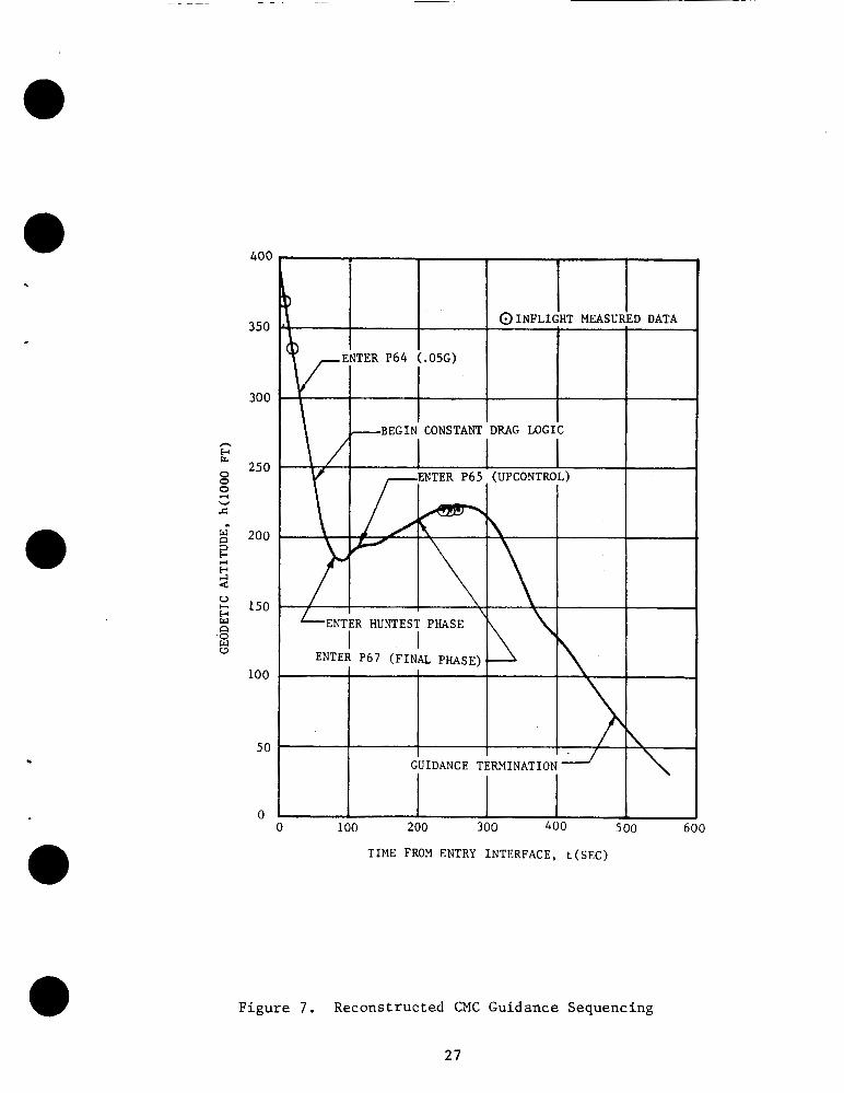
7 Recons t ruc t ed CMC Guidance Sequencing . . . . . . . . . . . . . . 27
8 Apollo 11 Touchdown Coordina tes . . . . . . . . . . . . . . . . . 28
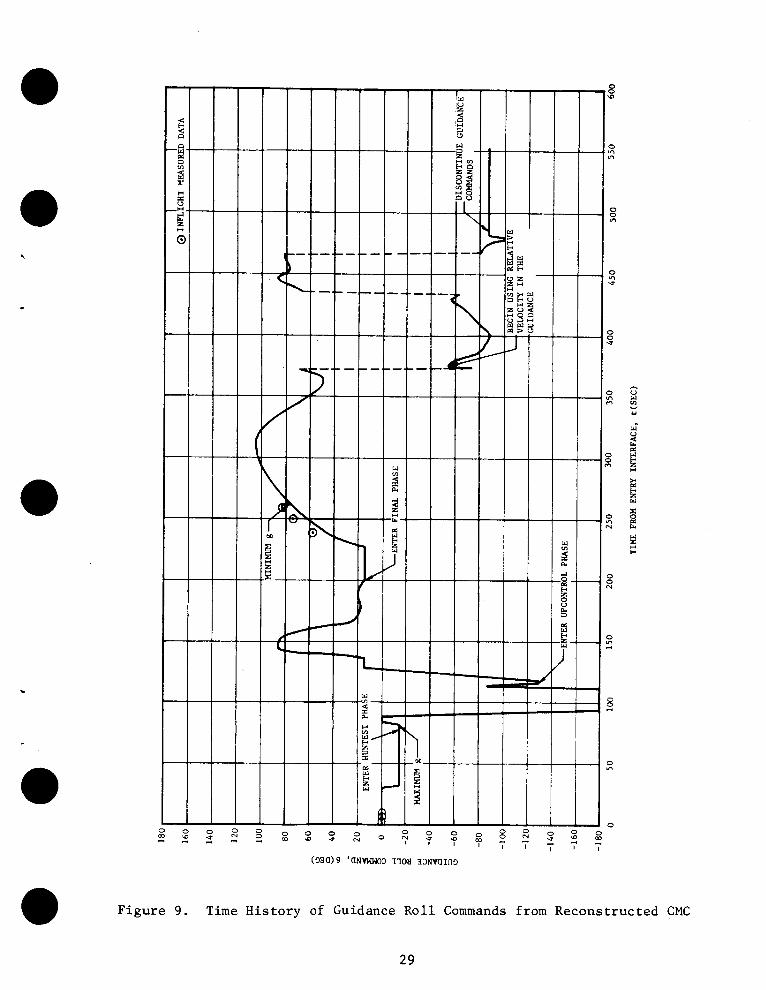
9 Time H i s t o r y of Guidance Rol l Commands from Recons t ruc ted CMC . . 29
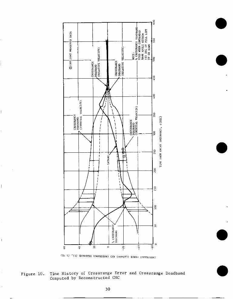
10 T ime H i s t o r y of Crossrange Error and Crossrange Deadband Computed by Recons t ruc ted CMC . . . . . . . . . . . . . . . . . . 30
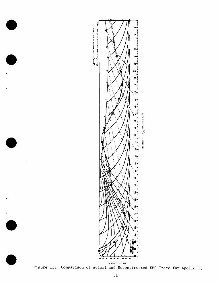
11 Comparison of Ac tua l and Recons t ruc ted EMS Trace f o r A p o l l o l l . . . . . . . , . . . . . . . . . . . . . . . . . . . . 31
1 2 F i n a l En t ry Pad f o r Apollo 11 . . . . . . . . . . . . . . . . . . 32
v i i
APOLLO 11 ENTRY POSTFLIGHT ANALYSIS
By Robert H . Manders Guided En t ry Systems S e c t i o n
TRW Systems Group
1. SUMMARY
Th i s r e p o r t p r e s e n t s t h e p o s t f l i g h t e v a l u a t i o n of t h e o p e r a t i o n o f t h e Apol lo 11 Command Module Computer (CMC) and a s s o c i a t e d systems d u r i n g t h e e n t r y phase of t h e Apollo 11 mission. The emphasis of t h i s r e p o r t i s p l a c e d on t h e o p e r a t i o n of t h e Command Module Computer (CMC), t h e Ent ry Monitor System (EMS), and a n e v a l u a t i o n of t h e e n t r y mon i to r ing procedures as d e f i n e d f o r t h e Apollo 11 e n t r y phase. Eva lua t ion of the CMC w a s com- p l i c a t e d by t h e l a c k of i n f l i g h t t e l eme t ry (TM) d a t a . The o n l y d a t a a v a i l a b l e f o r u se i n t h e a n a l y s i s was a s c a t t e r i n g of downlink d a t a picked up by ARIA a i r c r a f t , r ecove ry o p e r a t i o n s d a t a , and t h e EMS s c r o l l p a t t e r n . The a n a l y s i s has shown t h a t t h e CMC performed p r o p e r l y throughout t h e e n t r y phase . The onboard CMC-computed p o s i t i o n a t touchdown was 169.15 degrees w e s t l o n g i t u d e and 13.30 degrees no r th l a t i t u d e , approximate ly 1 . 7 n a u t i c a l m i l e s from t h e p lanned touchdown p o i n t . The s imula t ed CMC p o s i t i o n a t touchdown was 169.14 degrees west l o n g i t u d e and 13.34 degrees n o r t h l a t i t u d e .
S
Recons t ruc t ion o f t h e a c t u a l environment w a s o b t a i n e d through t h e use o f the EMS s c r o l l p a t t e r n trace and t h e onboard CMC s o l u t i o n f o r t h e onboard r e f e r e n c e t r a j e c t o r i e s a t ex i t from t h e Huntest phase as recorded by t h e ARIA a i r c r a f t . T h i s r e c o n s t r u c t i o n i n d i c a t e s t h a t t h e e n t r y f l i g h t p a t h a n g l e from t h e 21-day b e s t e s t i m a t e t r a j e c t o r y (BET) i s d i f f e r e n t from t h e e n t r y f l i g h t p a t h a n g l e which b e s t f i t s a l l a v a i l a b l e d a t a f o r t h e A p o l l o l l e n t r y phase .
An e v a l u a t i o n o f t h e recommended e n t r y mon i to r ing p rocedures i n d i c a t e s t h a t t h e p rocedures were fo l lowed by t h e crew and a l l c r i t i c a l t e s t s per - formed by t h e crew p r i o r t o and dur ing t h e e n t r y phase were s u c c e s s f u l and t r u l y i n d i c a t e d t h e s t a t u s of t h e e n t r y onboard sys t ems .
Th i s r e p o r t h a s been p repa red as a Supplement 10 t o t h e Apollo 11 Mission
Repor t (MSC - 00171).
1
2 . INTRODUCTION
2 . 1 Purpose
The pr imary o b j e c t i v e of t h i s r e p o r t i s t o p r e s e n t an e v a l u a t i o n of t h e Apollo 11 e n t r y guidance, nav iga t ion , and c o n t r o l system (GNCS). Secondly, a r e c o n s t r u c t i o n of t h e e n t r y environment u t i l i z i n g t h e e n t r y moni tor system (EMS) s c r o l l p a t t e r n trace and downlink d a t a o b t a i n e d by ARIA a i r c r a f t is p resen ted . No e n t r y t e l e m e t r y (TM) d a t a was a v a i l a b l e from t h e Apollo 11 miss ion . Th i rd ly , an e v a l u a t i o n of the Apolio e n t r y mon i to r ing procedures i s p resen ted . T h i s work w a s performed accord ing t o t h e agreement i n Reference 1.
't
2.2 General D e s c r i p t i o n of Contents
Th i s r e p o r t i s broken i n t o four areas of i n t e r e s t : Ent ry Cond i t ions , Environment Recons t ruc ' t ion , CMC Evalua t ion , and Eva lua t ion of Ent ry Monitor- i n g procedures . The con ten t of each s e c t i o n i s desc r ibed below:
S e c t i o n 3 p r e s e n t s t h e e n t r y s t a t e v e c t o r s u t i l i z e d i n t h e r econs t ruc - t i o n . The f i n a l r e e n t r y s t a t e vec to r from t h e Real Time Computing Complex (RTCC) c a l l e d CROX880 was u t i l i z e d f o r t h e CMC wh i l e a modi f ied v e r s i o n of t h e 21-day BET e n t r y state v e c t o r was u t i l i z e d i n t h e environment recon- s t r u c t i o n . 0
S e c t i o n 4 , which d e s c r i b e s the environment r e c o n s t r u c t i o n , p r e s e n t s t h e CM aerodynamics, atmosphere model and CM m a s s p r o p e r t i e s used t o perform t h e a n a l y s i s . The d i f f e r e n c e s between t h e 21-day BET e n t r y state v e c t o r and t h e v e c t o r u t i l i z e d t o o b t a i n t h e b e s t e n t r y t r a j e c t o r y d a t a f i t are p resen ted .
T r a j e c t o r y parameters from t h e r e c o n s t r u c t i o n are p resen ted .
S e c t i o n 5 d i s c u s s e s t h e ope ra t ion of t h e CMC du r ing t h e e n t r y phase of Apollo 11. d i s c u s s i o n of t h e s i g n i f i c a n t events p r e s e n t e d are from t h e r e c o n s t r u c t e d t r a j e c t o r y . ded by t h e ARIA a i r c r a f t are compared t o t h e r e c o n s t r u c t i o n .
S ince no TM d a t a is a v a i l a b l e t h e program sequencing and t h e
The r e f e r e n c e t r a j e c t o r y d a t a c a l c u l a t e d by t h e CMC and r eco r -
Also d i s c u s s e d i n Sec t ion 5 is a summary of t h e EMS o p e r a t i o n . m
Described i n Sec t ion 6 are the e n t r y moni tor ing procedures u t i l i z e d f o r t h e Apollo 11 miss ion . p o i n t of t h e f l i g h t crew u t i l i z a t i o n and t h e performance of t h e e n t r y moni- t o r i n g p rocedures f o r t h e s p e c i f i c c a s e of t h e Apollo 11 e n t r y .
These procedures are eva lua ted from t h e s t and-
3
3 . ENTRY CONDITIONS
The e n t r y s t a t e v e c t o r s used f o r t h e Apollo 11 p o s t f l i g h t a n a l y s i s were o b t a i n e d from two sources : the RTCC CROX880 s t a t e v e c t o r and t h e 21- day BET.
The BET i n d i c a t e s t h a t t h e Apollo 11 command module e n t e r e d t h e e a r t h ' s a tmosphere, d e f i n e d a t a geodet ic a l t i t u d e of 400,000 f e e t , a t 195 hoiurs 03 minutes 05.66 seconds a f t e r l i f t o f f . The e n t r y state v e c t o r ob- t a i n e d from t h e BET a t t h i s t i m e i s as fo l lows:
r I n e r t i a l v e l o c i t y 36,194.368 € t / sec
I n e r t i a l f l i g h t p a t h a n g l e -6.48 deg
I n e r t i a l azimuth 50.1761 deg
Longi tude 171.9603 deg E a s t
Geodet ic L a t i t u d e 3.1933 deg South
Geodet ic A l t i t u d e 400,000.72 f t
The e n t r y s t a t e v e c t o r on board the CMC was based on t h e RTCC CROX880 vec- t o r . The v e c t o r corresponding t o t h i s t i m e was s l i g h t l y d i f f e r e n t from t h e BET s t a t e v e c t o r . It i s a s fo l lows:
I n e r t i a l v e l o c i t y 36,195.287 f t l s e c
I n e r t i a l f l i g h t p a t h a n g l e -6.4875 deg
I n e r t i a l azimuth 50.1823 deg
Longitude 171.9622 deg E a s t
Geodet ic L a t i t u d e 3.1968 deg South
Geodet ic A l t i t u d e 398,867.97 f t
The a n a l y s i s w a s performed u t i l i z i n g t h e above s t a t e v e c t o r s ; t h e CMC simu- l a t i o n w a s i n i t i a l i z e d w i t h t h e RTCC v e c t o r and t h e environment w a s i n i t i a l - i z e d w i t h t h e 21-day BET v e c t o r . U n s a t i s f a c t o r y r e s u l t s were o b t a i n e d . The maximum-g exper ienced d u r i n g t h e i n i t i a l a tmospheric p e n e t r a t i o n a s recorded on t h e EMS s c r o l l p a t t e r n could not b e achieved w i t h t h e above c o n d i t i o n s . Also a n adequate r e c o n s t r u c t i o n of t h e GNCS r e f e r e n c e t r a j e c t o r y s o l u t i o n a t t e r m i n a t i o n of t h e Huntest Phase could n o t b e o b t a i n e d .
'r
5

It h a s been found, a s a r e s u l t o f t h i s a n a l y s i s , t h a t t h e f o l l o w i n g e n t r y s t a t e v e c t o r is a b e t t e r estimate of e n t r y c o n d i t i o n s t h a n t h e 21-day BET :
I n e r t i a l v e l o c i t y 36,194.368 f t l s e c
I n e r t i a l f l i g h t p a t h a n g l e -6.5230 deg
I n e r t i a l azimuth 50.1761 deg
Longitude 171.1960 deg East
Geodet ic L a t i tude 3.1933 deg South
Geodet ic A l t i t u d e 400,000.72 f t
This s t a t e v e c t o r i s -0.043 d e g r e e i n f l i g h t p a t h a n g l e d i f f e r e n t from t h e BET and when u t i l i z e d f o r environment i n i t i a l i z a t i o n , r e s u l t s i n a n e x c e l l e n t r e c o n s t r u c t i o n o f t h e e n t r y t r a j e c t o r y flown by t h e A p o l l o 11 CM.
6
4. ENVIRONMENT RECONSTRUCTION
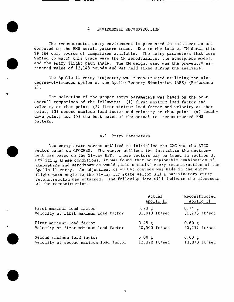
The r e c o n s t r u c t e d e n t r y environment i s p r e s e n t e d i n t h i s s e c t i o n and compared t o t h e EMS s c r o l l p a t t e r n trace. Due t o t h e l a c k of TM d a t a , t h i s i s t h e o n l y s o u r c e of comparison a v a i l a b l e . The e n t r y parameters t h a t were v a r i e d t o match t h i s trace were t h e CM aerodynamics, t h e atmosphere model, and t h e e n t r y f l i g h t p a t h angle . The CM weight used was t h e pre-en t ry es - t i m a t e d v a l u e o f 12,148 pounds and w a s h e l d f i x e d d u r i n g t h e a n a l y s i s .
Y
The Apollo 11 e n t r y t r a j e c t o r y w a s r e c o n s t r u c c e d u t i l i z i n g t h e s i x - degree-of-freedom o p t i o n of t h e Apollo Reentry S imula t ion (ARS) (Reference 2)
The s e l e c t i o n of t h e p r o p e r e n t r y parameters w a s based on t h e b e s t o v e r a l l comparison of t h e fol lowing: (1) f i r s t maximum l o a d f a c t o r and v e l o c i t y a t t h a t p o i n t ; (2) f i r s t minimum l o a d f a c t o r and v e l o c i t y a t t h a t p o i n t ; ( 3 ) second maximum l o a d f a c t o r and v e l o c i t y a t t h a t p o i n t ; ( 4 ) touch- down p o i n t ; and ( 5 ) t h e b e s t match of t h e a c t u a l t o r e c o n s t r u c t e d EMS p a t t e r n .
4 .1 Entry Parameters
The e n c r y s t a t e v e c t o r u t i l i z e d t o i n i t i a l i z e t h e CMC was t h e RTCC v e c t o r based on CROX880. The v e c t o r u t i l i z e d t h e i n i t i a l i z e t h e environ- ment w a s based on t h e 21-day BET. These v e c t o r s may be found i n S e c t i o n 3. U t i l i z i n g t h e s e c o n d i t i o n s , i t w a s found t h a t no r e a s o n a b l e combinat ion of atmosphere and aerodynamics would y i e l d a s a t i s f a c t o r y r e c o n s t r u c t i o n of t h e Apollo 11 e n t r y . f l i g h t p a t h a n g l e t o t h e 21-day BET s t a t e v e c t o r and a s a t i s f a c t o r y e n t r y r e c o n s t r u c t i o n w a s o b t a i n e d . The fo l lowing d a t a w i l l i n d i c a t e t h e c l o s e n e s s of t h e r e c o n s t r u c t i o n :
An adjus tment of -0.043 degrees was made i n t h e e n t r y
Actua l Recons t ruc ted Apollo 11 Apollo 11
F i r s t maximum load f a c t o r 6.73 g 6.74 g V e l o c i t y a t f i r s t maximum l o a d f a c t o r 31,810 f t l s e c 31,776 f t l s e c
L F i r s t minimum l o a d f a c t o r 0.48 g 0.60 g V e l o c i t y a t f i r s t minimum load f a c t o r 20,500 f t l s e c 20,257 f t / s e c
Second maximum l o a d f a c t o r 6.00 g 6.00 g V e l o c i t y a t second maximum load f a c t o r 12,390 f t / s e c 13,070 f t l s e c
7

The actual Apollo 11 d a t a w a s o b t a i n e d from t h e EMS s c r o l l p a t t e r n and tlie r e c o n s t r u c t e d d a t a is EMS v e l o c i t y and EMS load f a c t o r froiii the AI?:: CPZC s imu la t ion.
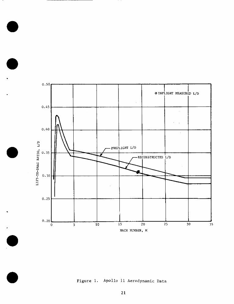
The r econs t ruc t ed aerodynamics, F igu re 1, cor respond t o a hype r son ic ( M ’ 29.5) CM l i f t - t o - d r a g (L/D) r a t i o of 0.282. Th i s aerodynamic d a t a f i t s t h e l i m i t e d f l i g h t d a t a ob ta ined by t h e ARIA a i r c r a f t . The a tmospher ic model which y ie lded b e s t r e s u l t s w a s t h e 30 degree North L a t i t u d e January atmosphere (Reference 3 ) . U t i l i z i n g t h e s t a t e v e c t o r s from S e c t i o n 3 and t h e aerodynamic and atmosphere d e s c r i b e d above r e s u l t s i n t h e b e s t recon- s t r u c t e d t r a j e c t o r y o b t a i n a b l e w i t h t h e d a t a a v a i l a b l e . P e r t i n e n t t ra jec- t o r y t i m e h i s t o r i e s are prese i l ted i n F i g u r e s 2 through 6 . The r e c o n s t r u c t e d t r a j e c t o r y touchdown po in t i s a t 169.14 degrees w e s t l o n g i t u d e and 13.34 degrees North l a t i t u d e o r approximate ly 1.80 n a u t i c a l m i l e s from t h e planned touchdown target (F igure 8 ) . T h e d i f f e r e n c e i n c ros s range between a c t u a l CMC and s imula ted CMC can be c o n t r i b u t e d t o t h e Lateral Logic Deadband.

5 . CMC EVALUATION
The purpose of t h i s s e c t i o n i s t o p r e s e n t a n e v a l u a t i o n of t h e Apollo 11 GNCS system. A d e s c r i p t i o n o f the guidance s y s t e m ' s o p e r a t i o n w i t h res- p e c t t o v a r i o u s t r a j e c t o r y parameters and t e r m i n a l o b j e c t i v e s i s p r e s e n t e d . The a v a i l a b l e i n f l i g h t CMC d a t a recorded by t h e ARIA a i r c r a f t : is t h e n com- pared t o t h e r e c o n s t r u c t e d CMC d a t a .
5 . 1 D e s c r i p t i o n of CMC Opera t ion
The Apollo 11 e n t r y c o n s i s t e d of f o u r phases: e n t r y i n i t i a l i z a t i o n
6 5 ) , and FINAL PHASE (Program 67). Programs 61 and 62 o p e r a t e d c o r r e c t l y and sequenced t o Program 63 a t t h e proper t i m e . The CMC remained i n Pro- gram 63 u n t i l t h e edge of t h e s e n s i b l e atmosphere (0.05g) w a s reached . t h i s p o i n t a tmospher ic guidance began. Once t h e computed d r a g leve l , KA, w a s reached , a c o n s t a n t d r a g level, DO, w a s flown u n t i l t h e p r e d i c t e d range t o t a r g e t (HUNTEST Phase) w a s w i t h i n 25 n a u t i c a l m i l e s of t h e a c t u a l range t o go ( IDIFF] 5 25). p o i n t and w a s f lown u n t i l t h e p r e d i c t e d v a l u e of d r a g t o t e r m i n a t e UPCONTROL (DL) w a s reached and t h e guidance t r a n s f e r r e d t o FINAL PHASE (Program 6 7 ) . The t r a j e c t o r y flown i n FINAL PHASE r e s u l t e d i n a touchdown a t 13.30 d e g r e e s n o r t h l a t i t u d e and 169.15 degrees west l o n g i t u d e o r approximate ly 1 . 7 nau- t i c a l m i l e s from t h e planned touchdown p o i n t . No d a t a i s a v a i l a b l e on t h e a c t u a l CMC sequencing. F i g u r e 7 p r e s e n t s t h e r e c o n s t r u c t e d CMC sequencing and t h e r e s p e c t i v e touchdown p o i n t s are p r e s e n t e d i n F igure 8. The recon- s t r u c t e d CMC w a s o b t a i n e d from t h e six-degree-of-freedom v e r s i o n of t h e A R S program u t i l i z i n g t h e guidance l o g i c . A l l d i s c u s s i o n s which f o l l o w on t h e t r a j e c t o r y e v e n t s w i l l reflect t h e r e c o n s t r u c t e d CMC.
V and a t t i t u d e h o l d (Program 6 3 ) , pos t 0.05g (Program 6 4 ) , UPCONTROL (Program
A t
The UPCONTROL phase (Program 65) w a s e n t e r e d a t t h i s
5 . 1 . 1 Ent ry I n i t i a l i z a t i o n and A t t i t u d e Hold (Program 63) . - The guidance system w a s i n i t i a t e d w i t h t h e proper s w i t c h e s and c o n t r o l con- s t a n t s i n Program 63. A t a geodet ic a l t i t u d e of 398,867.97 f e e t , t h e simu- l a t e d CMC computed a n i n e r t i a l v e l o c i t y of 36,195.29 f ee t p e r second and an i n e r t i a l f l i g h t p a t h a n g l e of -6.488 degrees . The ground e l a p s e d t ime from l i f t o f f t o e n t r y i n t e r f a c e was 195 hours 03 minutes 05.7 seconds . The e n t r y p o i n t w a s l o c a t e d a t a g e o d e t i c l a t i t u d e of 23.193 degrees s o u t h and a l o n g i t u d e of 171.196 d e g r e e s eas t which r e s u l t e d i n a r e l a t i v e range of 1497 n a u t i c a l m i l e s and an i n e r t i a l range of 1585 n a u t i c a l m i l e s . On- se t o f 0.05g occurred 30 seconds a f t e r e n t r y a t a g e o d e t i c a l t i t u d e of 289,926 f e e t . The s imula ted CMC then c a l c u l a t e d t h e r e f e r e n c e d r a g l e v e l f o r t h e c o n s t a n t d r a g l o g i c , D O , and t h e command module 's p o s i t i o n i n t h e e n t r y c o r r i d o r r e l a t i v e t o t h e l i f t v e c t o r o r i e n t a t i o n l i n e . The v a l u e s of KA and D O , based on t h e i n e r t i a l v e l o c i t y a t O.O5g, were 1 . 4 1 8 g ' s and 3 . 9 9 1 g ' s r e s p e c t i v e l y , whi le t h e commanded bank a n g l e was zero d e g r e e s .
c
9

5.1.2 P o s t 0.05g (Program 64) . - The s imula t ed CMC then sequenced t r ?
program 64 a t 0.05g. 6 3 w a s maintained u n t i l t h e d r a g l e v e l became g r e a t e r t han 1 .426g1s , 52 seconds a f t e r e n t r y , a t which t i m e t h e guidance system began t h e c o n s t a n t d r a g p o r t i o n of t h e t r a j e c t o r y .
The l i f t - u p a t t i t u d e commanded a t t h e end of program
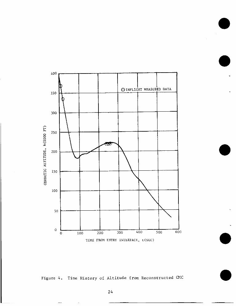
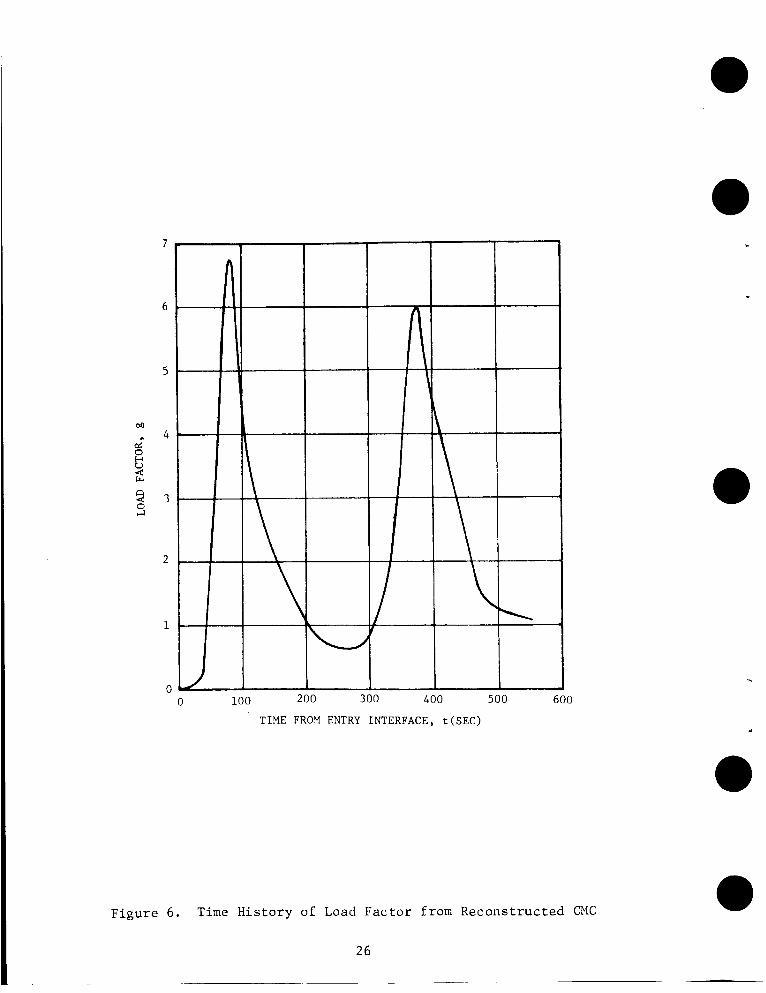
The L I D c o n t r o l e q u a t i o n i n t h e c o n s t a n t d rag l o g i c i s d r i v e n by d rag and a l t i t u d e ra te e r r o r s based on a computed r e f e r e n c e t r a j e c t o r y . a l l y t h e commanded bank ang le w a s z e r o deg rees ( L i f t v e c t o r up) (See F igu re 9) due t o t h e l a r g e n e g a t i v e a l t i t u d e ra te . The r e c o n s t r u c t e d a l t i t u d e r a t e became less nega t ive than -700 f t / s e c 7 8 seconds a f t e r e n t r y (See F igu re 2) and t h e s imula t ed guidance sys tem began ranging p r e d i c t i o n s . The r e c o n s t r u c t e d i n e r t i a l range t o t h e t a r g e t a t t h i s t i m e w a s 1122 n a u t i c a l mi les (See Fig- u r e 3 ) . Due to t h e l a r g e energy leve l of t h e command module, an ove r shoo t t r a j e c t o r y w a s p r e d i c t e d , hence t h e guidance system remained i n t h e c o n s t a n t d rag l o g i c . The maximum l o a d f a c t o r , 6 .73g1s , occu r red 8 2 seconds a f t e r e n t r y and t h e f i rs t minimum a l t i t u d e (See F igu re 4 ) , 182,109 f e e t , occu r red 88 sec - onds a f t e r en t ry . When t h e l o a d f a c t o r dropped below 5 .44g ' s t h e guidance system p rope r ly commanded a bank ang le of -180 degrees .
I n i t i -
The guidance remained i n t h e HUNTEST/CONSTANT DRAG l o g i c u n t i l t h e energy level was decreased t o a l l o w t h e d e f i n i t i o n of a s u c c e s s f u l r e f e r - ence t r a j e c t o r y ( p r e d i c t e d range t o t a r g e t w i t h i n 25 n a u t i c a l miles of a c t u a l range t o t a r g e t ) . T h i s r e f e r e n c e t r a j e c t o r y is shown i n Table I and i s compared t o the a c t u a l (ob ta ined from ARIA d a t a ) .
5.1.3 UPCONTROL Phase (Program 65) . - With t h e d e f i n i t i o n of t h e r e f e r e n c e t r a j e c t o r y 118 seconds a f t e r e n t r y c o n t r o l t r a n s f e r r e d t o t h e UPCONTROL phase. The a c t u a l v e l o c i t y , a l t i t u d e ra te , and a c c e l e r a t i o n a t t h e t i m e of t r a n s f e r were 26,832.5 f t l s e c , 75.26 f t l s e c , and 3.405g, res- p e c t i v e l y .
The UPCONTROL r e f e r e n c e t r a j e c t o r y i s de f ined based on f o u r q u a n t i t i e s : a c c e l e r a t i o n a t p u l l o u t (AO), v e l o c i t y a t p u l l o u t (V l ) , a c c e l e r a t i o n a t UP- CONTROL t e rmina t ion (DL), and v e l o c i t y a t UPCONTROL t e r m i n a t i o n (VL). The v a l u e s of AO, V 1 , DL, and VL w e r e 3.1763, 26,334.2 f t l s e c , 1.057g, and 22,090.8 f t l s e c , r e s p e c t i v e l y . These d a t a were ob ta ined from ARIA d a t a and are compared to t h e r e c o n s t r u c t e d t r a j e c t o r y i n Table I.
The r e c o n s t r u c t e d guidance f l e w t h e UPCONTROL r e f e r e n c e t r a j e c t o r y and achieved t h e va lue DL 200 seconds a f t e r e n t r y wi th a v e l o c i t y of 21,311.4 f t l s e c .
5 .1 .4 FINAL PHASE (Program 67) . - The r e c o n s t r u c t e d guidance system sequenced t o the f i n a l phase l o g i c when t h e i n e r t i a l v e l o c i t y w a s 21,301 f t / s e c (See F igure 7 ) ; t h e a l t i t u d e r a t e w a s 306 f e e t p e r second. The CPlwas i n a l i f t - u p a t t i t u d e and t h e i n e r t i a l range t o t h e t a r g e t w a s 615 n a u t i c a l mi les . downrange error of 23 n a u t i c a l m i l e s .
The f i r s t range p r e d i c t i o n i n FINAL PHASE r e s u l t e d i n a p r e d i c t e d The p r e d i c t e d downrange e r r o r then

c
i n c r e a s e d t o a 30 n a u t i c a l m i l e undershoot a t 216 seconds a f t e r e n t r y . The p r e d i c t e d clownrange e r r o r was increased t o a 29 n a u t i c a l m i l e overshoot a t 260 seconds a f t e r e n t r y . The p r e d i c t e d downrange e r r o r remained p o s i t i v e ( o v e r s h o o t ) u n t i l t h e i n e r t i a l v e l o c i t y became less than 12 ,833 f e e t p e r sec- ond, 381 seconds a f t e r e n t r y . l i z i n g reliti7;e v r l o c i t y i n t h e range p r e d i c t i o n s i r p h c z cf t h e i n e r t i a l v e l o c i t y . h r i n g s imula ted FINAL PHASE t h e a l t i t L d e reaci-.?: r e l a t i v e maxi- num of 2Zu,U72 f e e t , 256 seconds a f t e r e n t r y , w h i l e t h e Load f a c t o r decreased t o a r e l a t i v e minimum of 0.60~5, 262 seconds a f t e r e n t r y . The l o a d f a c t o r i n - creases t o a second maximum of 5.98g, 374 seconds a f t e r e n t r y . The o v e r a l l t r a j e c t o r y flat.-- !n f i n a l phase w a s a t an a v e r a g i F -.' angle of 70 d e g r e e s and r e s u l t e d i r ? a touchdown a t a g e o d e t i c l a t i t u d e o f 13.300 d e g r e e s n o r t h and a l o n g i t u d e of 169.150 d e g r e e s west, 1.69 n a u t i c a l miles from t h e t a r g e t , as shown i n F i g u r e 8.
A t t h i s p o i n t t h e guidance s y s t e m began u t i -
Three l a t e ra l swi tches occurred d u r i n g s imula ted FINAL PHASE. A l a t - e r a l s w i t c h o c c u r s whenever t h e c r o s s r a n g e deadband i s exceeded. Crossrange deadband i s computed by t h e guidance and i s p r o p o r t i o n a l t o t h e s p a c e c r a f t ' s l a t e r a l ranging c a p a b i l i t y a t i t s c u r r e n t v e l o c i t y . I f t h e r o l l command i s w i t h i n +15 d e g r e e s of f u l l l i f t up o r down, t h e deadband is h a l v e d t o account f o r t h e smaller l a t e ra l f o r c e . The l a t e r a l s w i t c h e s occurred a t 376 seconds , 436 seconds, and 468 seconds a f t e r e n t r y , as i n d i c a t e d i n F i g u r e 10.
5.2 CMC S imula t ion
A computer s i m u l a t i o n o f the CMC o p e r a t i o n d u r i n g e n t r y w a s made. The e n t r y parameters o b t a i n e d from t h e s i m u l a t i o n were t h e n compared t o t h o s e recorded by ARIA a i r c r a f t .
5 .2 .1 Simulat ion.- The computer s i m u l a t i o n of t h e CMC o p e r a t i o n w a s made w i t h t h e Apollo Reentry Simulat ion (ARS) program u t i l i z i n g s ix-degree- of freedom. The s imula ted CMC w a s i n i t i a l i z e d w i t h t h e e n t r y s t a t e v e c t o r o b t a i n e d from t h e RTCC v e c t o r CROX 880 a t a ground e l a p s e d t i m e of 195 hours 03 m i n u t e s and 05.66 seconds. The environment w a s i n i t i a l i z e d u t i l i z i n g t h e modi f ied 21-day BET v e c t o r as d i s c u s s e d i n S e c t i o n 3 .
5.2.2 Comparison.- The r e s u l t s o b t a i n e d from t h e s i m u l a t i o n (simu- l a t e d CMC) were compared t o t h e CMC computat ions recorded by t h e A R I A and w e r e i n c l o s e agreement. of t i m e and t h e r e f o r e no t i m e h i s t o r y comparisons a r e made h e r e i n . Due t o t h e lack of TM d a t a , t h e program sequencing o b t a i n e d from t h e s i m u l a t e d CMC i s p r e s e n t e d as t h a t of t h e a c t u a l CMC. These r e c o n s t r u c t e d d a t a are shown i n F i g u r e s 2 through 6 and i n Tables I and 11.
The a c t u a l CMC da t a i s n o t a v a i l a b l e as a f u n c t i o n
Table I1 p r e s e n t s a comparison between t h e a c t u a l and t h e r e c o n s t r u c t e d c o n d i t i o n s a t r e f e r e n c e t r a j e c t o r y s o l u t i o n ( t e r m i n a t i o n of HUNTEST Phase, P-64) . The a c t u a l c o n d i t i o n s were o b t a i n e d by s o l v i n g t h e f o l l o w i n g e q u a t i o n s s i m u l t a n e o u s l y f o r v e l o c i t y , a l t i t u d e r a t e , and a c c e l e r a t i o n :
11
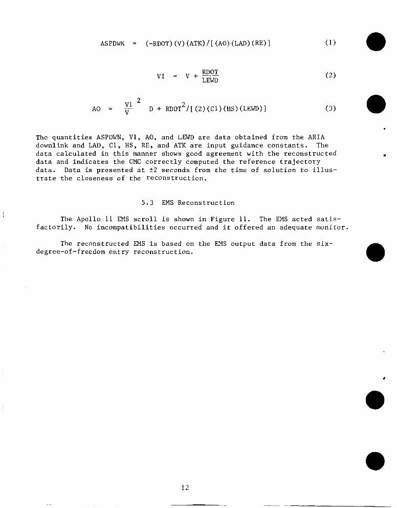
ASPDWN = (-RDOT) (V) (ATK) / [ (AO) (LAD) (RE) ]
RDOT v1 = v + - LEWD
2 A 0 = - v1 D + RDOT2/[ ( 2 ) (Cl) (HS) (LEWD)] ( 3 ) V
The q u a n t i t i e s ASPDWN, V1, AO, and LEWD are d a t a o b t a i n e d from t h e A R I A downlink and LAD, C1, HS, RE, and ATK are i n p u t guidance c o n s t a n t s . The d a t a c a l c u l a t e d i n t h i s manner shows good agreement w i t h t h e r e c o n s t r u c t e d d a t a and i n d i c a t e s t h e CMC c o r r e c t l y computed t h e r e f e r e n c e t r a j e c t o r y d a t a . Data is p r e s e n t e d a t 22 seconds from t h e t i m e o f s o l u t i o n t o i l l u s - t r a t e t h e c l o s e n e s s of t h e r e c o n s t r u c t i o n .
5 .3 EMS R e c o n s t r u c t i o n
The Apollo 11 EMS s c r o l l i s shown i n F i g u r e 11. The EMS a c t e d sa t i s - f a c t o r i l y . No i n c o m p a t i b i l i t i e s occur red and i t o f f e r e d a n adequate moni tor .
The r e c o n s t r u c t e d EMS i s based on t h e EMS o u t p u t d a t a from t h e six- degree-of-freedom e n t r y r e c o n s t r u c t i o n .
12

6. EVALUATION OF THE ENTRY OPERATIONS AND MONITORING PLAN
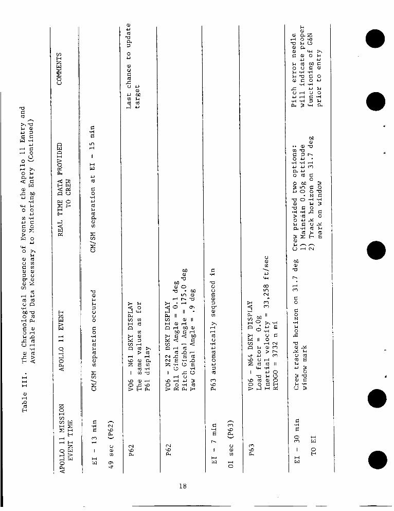
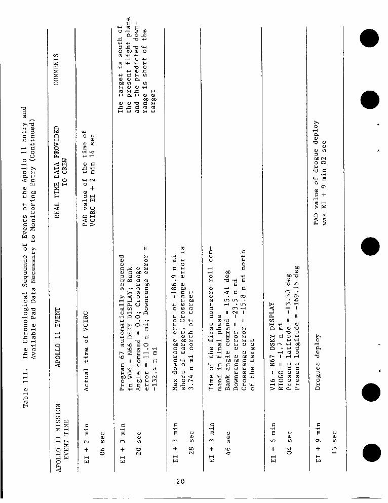
This s e c t i o n p r o v i d e s a c h r o n o l o g i c a l sequence of e v e n t s of crew o p e r a t i o n s w h i l e moni tor ing e n t r y . The d a t a p r e s e n t e d i s from t h e onboard t e l e m e t r y t a p e p r i o r t o t h e e n t r y i n t e r f a c e and from t h e A R I A a i r c r a f t and t h e r e c o n s t r u c t e d t r a j e c t o r y fo l lowing e n t r y i n t e r f a c e . The d.-ita i n d i c a t e s what t h e crew observed real t i m e and how t h e y responded i n t h e p r o c e s s of moni tor ing e n t r y . Table I11 p r e s e n t s t h e Apollo 11 sequence of e v e n t s i n a d d i t i o n t o PAD d a t a n e c e s s a r y t o monitor t h e onboard computer. a
6 . 1 Ent ry Monitor ing Plan P r i o r t o Ent ry I n t e r f a c e
8 An a d d i t i o n a l hor izon monitor check w a s performed a t E n t r y I n t e r f a c e minus 30 minutes (E1 - 30). The p i t c h gimbal a n g l e (PGA) from t h e e n t r y PAD ( F i g u r e 12) matched e x a c t l y w i t h t h e a c t u a l a t t h e t i m e of t h e check. Horizon t r a c k i n g w a s i n i t i a t e d by t h e command p i l o t a t E 1 - 30 minutes .
Program 61 w a s i n i t i a t e d 19 minutes p r i o r t o E I . The f i r s t DSKY d i s - p l a y i n Program 61 d i s p l a y e d t h e t a r g e t l a t i t u d e and l o n g i t u d e and l i f t vec- t o r o r i e n t a t i o n (LVO). The t a r g e t l a t i t u d e w a s 13.32 d e g r e e s n o r t h and l o n g i t u d e w a s 169.17 degrees w e s t ; the a c t u a l splashdown c o o r d i n a t e s were 13.30 d e g r e e s n o r t h and 169.15 degrees w e s t . up o r i e n t a t i o n . The second DSKY d i s p l a y d i s p l a y e d p r e d i c t e d v a l u e s of GMAX = 6 . 4 6 g ' s , v e l o c i t y a t E 1 = 36,184 f t f s e c and f l i g h t p a t h a n g l e a t E 1 = -6.46 degrees . These v a l u e s compared t o t h e a c t u a l c o n d i t i o n s of GMAX = 6.73g ' s , v e l o c i t y (EI) = 36,194 f t f s e c , and f l i g h t p a t h a n g l e (EI) = -6.52 d e g r e e s . The f i n a l DSKY d i s p l a y of P61 d isp layed t h e p r e d i c t e d i n e r t i a l range t o t h e t a r g e t a t 0.05g = 1418 n a u t i c a l m i l e s , p r e d i c t e d v e l o c i t y a t 0.05g = 36,261 f t l s e c , and p r e d i c t e d t i m e of 0.05g = E 1 + 28 seconds. o f i n e r t i a l range t o t a r g e t a t 0.05g w a s 1418 n a u t i c a l m i l e s and i n e r t i a l v e l o c i t y a t 0.05g w a s 36,275 f t f s e c . These v a l u e s compared f a v o r a b l y . The r e c o n s t r u c t e d t i m e of 0.05g occurred as p r e d i c t e d .
The LVO w a s d i s p l a y e d i n t h e
a The a c t u a l v a l u e
Program 62 w a s e n t e r e d a t E 1 - 16 minutes . The r e q u e s t f o r s e p a r a t i o n appeared immediately; consequent ly , t h e IMU w a s n e i t h e r r e v e r s e d nor unsa t - i s f a c t o r y . A t E 1 - 14 minutes , t h e p i t c h gimbal a n g l e check w a s performed. The p i t c h gimbal a n g l e w a s w e l l w i t h i n t h e a l l o w a b l e f i v e d e g r e e t o l e r a n c e .
CM/SM s e p a r a t i o n occurred a t E 1 - 13 minutes , 49 seconds . The command L p i l o t wai ted a f t e r s e p a r a t i o n t o i n s u r e adequate s e p a r a t i o n d i s t a n c e b e f o r e
maneuvering. The DSKY d i s p l a y of t a r g e t c o o r d i n a t e s t h e n appeared w i t h t h e l i f t v e c t o r o r i e n t a t i o n f o r e n t r y . The v a l u e s were t h e same as i n P61. The DSKY d i s p l a y of d e s i r e d gimbal a n g l e s t h e n appeared: R o l l = 0.1 d e g r e e , P i t c h = 175.0 d e g r e e s , and Yaw = .9 degree . The DSKY d i s p l a y of d e s i r e d gimbal a n g l e s w a s d i s p l a y e d u n t i l E 1 - 7 minutes , 01 seconds ; a t t h i s t i m e
a
1 3
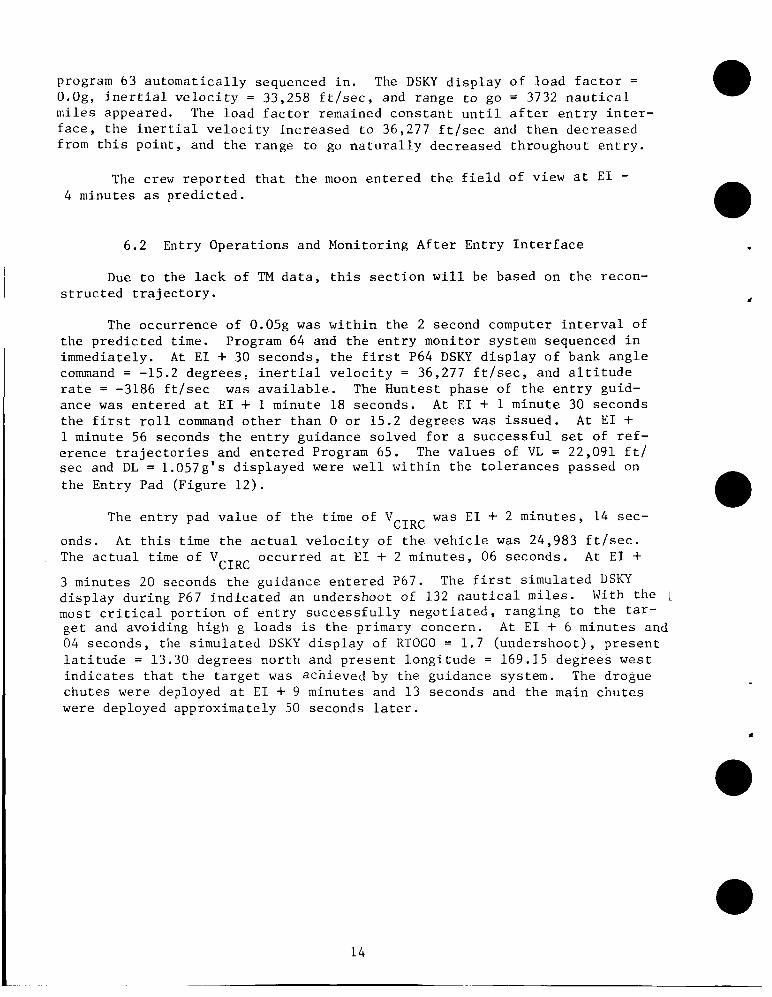
program 63 a u t o m a t i c a l l y sequenced i n . The DSKY d i s p l a y o f load f a c t o r = O.Og, i n e r t i a l v e l o c i t y = 33,258 f t / s e c , and range t o go = 3732 n a u t i c a l m i l e s appeared. The l o a d f a c t o r remained c o n s t a n t u n t i l a f t e r e n t r y i n t e r - f a c e , t h e i n e r t i a l v e l o c i t y i n c r e a s e d t o 36,277 f t / s e c and t h e n decreased from t h i s p o i n t , and t h e range t o go n a t u r a l l y decreased throughout e n t r y .
The crew r e p o r t e d t h a t t h e moon e n t e r e d t h e f i e l d of view a t E l - 4 minutes as p r e d i c t e d .
6.2 Entry Opera t ions and Monitor ing A f t e r Ent ry I n t e r f a c e
Due t o t h e l a c k of TM d a t a , t h i s s e c t i o n w i l l be based on t h e recon- s t r u c t ed t r a j e c t o r y .
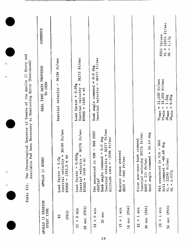
The occurrence of 0.05g w a s w i t h i n t h e 2 second computer i n t e r v a l of t h e p r e d i c t e d t i m e . Program 64 and t h e e n t r y monitor system sequenced i n immediately. A t E 1 + 30 seconds , t h e f i r s t P64 DSKY d i s p l a y o f bank a n g l e command = -15.2 degrees : i n e r t i a l v e l o c i t y = 36,277 f t / s e c , and a l t i t u d e ra te = -3186 f t / s e c was a v a i l a b l e . The Huntest phase of t h e e n t r y guid- ance w a s en te red a t E 1 + 1 minute 18 seconds. A t E 1 + 1 minute 30 seconds t h e f i r s t r o l l command o t h e r t h a n 0 o r 15.2 d e g r e e s w a s i s s u e d . A t E 1 + 1 minute 56 seconds t h e e n t r y guidance so lved f o r a s u c c e s s f u l set of r e f - e r e n c e t r a j e c t o r i e s and e n t e r e d Program 65. The v a l u e s of VL = 22,091 €t/ sec and DL = 1.057g ' s d i s p l a y e d were w e l l w i t h i n t h e t o l e r a n c e s passed on t h e Entry Pad (F igure 12) .
w a s E 1 + 2 m i n u t e s , 14 sec- C I R C The e n t r y pad v a l u e of t h e t i m e of V
onds. The a c t u a l time of V
3 minutes 20 seconds t h e guidance e n t e r e d P67. d i s p l a y d u r i n g P67 i n d i c a t e d an undershoot of 132 n a u t i c a l mi l e s . With t h e i most c r i t i c a l p o r t i o n of e n t r y s u c c e s s f u l l y n e g o t i a t e d , r a n g i n g t o t h e tar- g e t and avoiding h i g h g l o a d s i s t h e primary concern. A t E 1 + 6 minutes and 04 seconds, the s i m u l a t e d DSKY d i s p l a y of RTOGO = 1 . 7 ( u n d e r s h o o t ) , p r e s e n t l a t i t u d e = 13.30 d e g r e e s n o r t h and p r e s e n t l o n g i t u d e = 169.15 d e g r e e s w e s t i n d i c a t e s t h a t t h e t a r g e t w a s ach ieved by t h e guidance system. The drogue c h u t e s were deployed a t E1 + 9 minutes and 13 seconds and t h e main c h u t e s were deployed approximately 50 seconds l a t e r .
A t t h i s t i m e t h e a c t u a l v e l o c i t y of t h e v e h i c l e w a s 24,983 f t / s e c . occur red a t ET + 2 m i n u t e s , 06 seconds. A t E 1 +
C I R C The f i r s t s i m u l a t e d DSKY
14

Variable
Table I. Comparison Of The Actual CMC And Simulated CMC Reference Trajectory Data
Actual 2econstructed CMC CMC
Predicted Velocity at CM Pullout, C1 (ft/sec)
Predicted Acceleration at . CM Pullout, A0 (g)
Predicted Velocity at Termination of UPCONTROL, VL (ft/sec)
Predicted Acceleration at Termination of UPCONTROL, DL (g)
Predicted Range to CM Pullout, ASPDN (n. mi.)
Predicted Range to be Flown During UPCONTROL, ASPUP (n. mi.)
.
Predicted Range to be Flown During KEPLER, ASJKEP (n. mi.)
Predicted Range to be Flown During FINAL PHASE, ASP1 (n. mi.)
Predicted Gamma Correction to FINAL PHASE Range, ASP3 (n. mi.)
Total Range Prediction, ASP (n. mi.)
Reference L/D for UPCONTROL, LEkQ
26,334 26,601
3.176 3.521
22,090 22,038
1.057 1.054
-11.87 -20.48
181.934 193.890
0 0
528.662 525.667
246.05
945.775
246.05
945.118
0.15 0.15 c
15
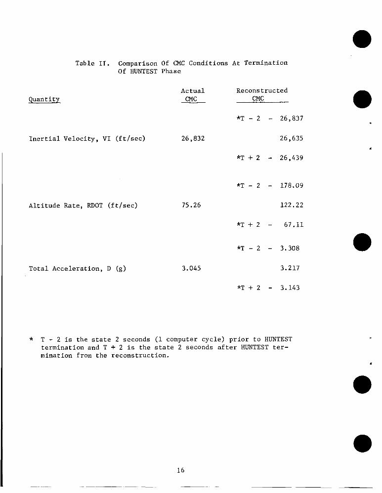
Table 11. Comparison Of CMC Conditions At Termination Of HUNTEST Phase
Quantity
Inertial Velocity, VI (ft/sec)
Altitude Rate, RDOT (ft/sec)
Total Acceleration, D (g)
Actual Reconstructed CMC CMC
*T - 2 - 26,837
26,832 26 , 635
75.26
3.045
*T + 2 - 26,439
*T - 2 - 178.09
122.22
*T + 2 - 67.11
*T - 2 - 3.308
3.217
*T + 2 - 3.143
* T - 2 is the state 2 seconds (1 computer cycle) prior to HUNTEST termination and T + 2 is the state 2 seconds after HUNTEST ter- mination from the reconstruction.

a C (d
h $4 u C w d d
0
c H H H
in H z E 0 V
n n w H
2 PI
z 0 H VI m w
w S E d
M aJ a 0
03 cn CJ
II
3 9 PI
PI
c E .d
0 m I
H w
c E .d
ul
I
H w U (d
a PI
a aJ u (d .ti U -4 c H
I4
d
m
d a PI
c .d E cn
I
H w
d
n.m m m a
d a PI
II .A u
. . . a a a a J a J a J M k k PIPIPI
M aJ a
4 a PI
c .d E
w
I
H W U (d
hl Q PC aJ U (d .d u .d C H
4
a aJ & aJ u C aJ m .d
hl a PI
c *d E a
I
H w
4
17
a C a n
ha k a J u 1 6.5
U A C - 1 0
U 0 -
?-I 4 h O N
33 a, C M u c 4 W k 0 0
U Lo .d u c
3 w o U
w O h
5 g
aJa C ? w 4
H H H
aJ 4 . . P a w
G .r( E ul d
I
H W U (d
C 0 -4 U (d k (d a a, m
i2 E \
a aJ k k 1 V V 0
C 0 .d U a N a a aJ v)
z 5 \
C *rl E m d
I
H w
aJ U a U a 3 0 U
aJ CJ C (d c V U
a, U M c n k ( d a I4u
hl 9 pi
18
C .d
a a, 0
3 aJ m
h 4 4 a V .d U a E 0 U 3 a m \o PI
5
C -4 E b
I H w
- m \D PI
V aJ m
0
W
-1
u aJ m U w 00 In hl
cl
. . I uo a k u a a a o 0 0 C H 3 I J H e ?
m u3 pi
L-b c 0 a c o u
M aJ
M a, a
C E O H m u I O
I3
*d
H W
.
u aJ m \ u w
m a J - 3 M 3 N O r l o r l CdN
c
.
V aJ rn \ U W
U m a m II
h U .I4 u 0 rl al 3 rl (d .d U &I aJ G H
d
u 9) cn \ u w 0 m \D m 4
- . u 4
n m
H u l
u r l a II L u
0 u + : H w o 3
N
u a, v) \
M U a J W a
b O b ‘ C J
O\o m II
II
a G h 8 5 0 0 u r l
aJ a J P
c
+ o m H w
n c - 3 -4 ul
d u + :
H w c o
d
U M a J a J m a
a\ c u m CdW u B u l 2 O b VI C J d
n G - 3 .d \D
d u + :
H w o m
0 0 0 0 M M e o u e
N d d O
II II II II
,“,“Y?
m u l M Z a J a
a2 u lu l
h
c m -d ul
E e 4
u + : H w u l
VI
19
V a, cn a 0
c .d E V ar
m c n
+ : H L1
20
c .d E u
a, m r n + a H w
e
M aJ
M a aJ a m
C
a m + e
0 H w
h 0 4 a a, a m a, rl M 0 Lc n
C
E U a, m c n
*d
+ 2 H w
L
.
0 .50
0.45
0.40
cc Ll \
E 0.35
2 2 Q
A 7 0.30 H h
cl H
0.25
0 .20
MACH NUMBER, M
Figure 1. Apollo 11 Aerodynamic Data
2 1

1000
0
8 -1000
8 -2000
w 5
w
n -3000
E a
-4000
-5000 200 300 400 500 600 0 100
TIME FROM ENTRY INTERFACE, t (SEC)
F i g u r e 2. Time H i s t o r y of A l t i t u d e Rate from Recons t ruc ted CMC
22
.

. c
0 100 200 300 4 00 500 6 00
TIME FROM ENTRY INTERFACE, t (SEC)
F i g u r e 3 . T i m e H i s t o r y of I n e r t i a l Range t o Ta rge t from Recons t ruc ted CMC
23
w Lu 0 0 0
c W n 3 w U w
d v
2
s V H
n 0 w 0
400
350
300
250
200
150
100
50
n 0 100
TIME
0
Figure 4 . Time History of Altitude from Reconstructed CMC
2 4

l-l w 3
:ONS
TIME FROM ENTRY INTERFACE, t (SEC)
F i g u r e 5 . T i m e H i s t o r y of Guidance Ve loc i ty from Recons t ruc ted CMC
25
0 100 200 300 400 500 600
TIME FRO?? ENTRY INTERFACE, t ( S E C )
F igu re 6. T ime H i s t o r y of Load F a c t o r from Recons t ruc ted CMC
26
~
.
c
400
350
300
n bl b 0 c, 0
c
250
rl v
w 200 Ei H w d
E 8
u H 150
n L?
100
50
0 3
Figure 7. Reconstructed CMC Guidance Sequencing
27

13.3
/' /
/ x / -\
13.31
CMC SIMULATION
/. TARGET n
X H
z 3 13.3
- 13.3( w
2E
26
13.24
I \CMC SIMULATION GROUNDTRACK
ESTIMATED RECO' 7 RY- 1 I 1
LONGITUDE, A (DEG WEST)
Figure 8. Apo l lo 11 Touchdown Coord ina te s
28
10
c
0 m 4
0 \o 3
0 U 3
0 N 3
0 E: 0 m 0 .o 0 U
0 0 VI
0 vl vl
0 0 Ih
0 VI U
0 .Y
3 n
3
3 v
3 v
2
3 2
3 n
0
h
u W rn
U
w
Y
Y
5
8
a W c z CI
2
2 E
L*
c
F i g u r e 9. T i m e H i s t o r y of Guidance R o l l Commands from Recons t ruc ted CMC
29
3 a
3 7 7
3 7
3 9 f
3 7
3 9 -
U w rn
u
n
v
w
2 2 w c z
c a c
Y
R Z ; " Z
2
6 Lu
w
c 0 0 N
0 m -
0 2
0 m
0
.
Figure 10. T i m e H i s t o r y Of Crossrange E r r o r and Crossrange Deadband Computed by Recons t ruc ted CMC
30
.
Figure 11. Comparison of Ac 1 ' \ n l l \ . w n 7 5 ~ Y C l i ?
:tual and Reconstruc :ted EMS Trace for Apollo 11
31
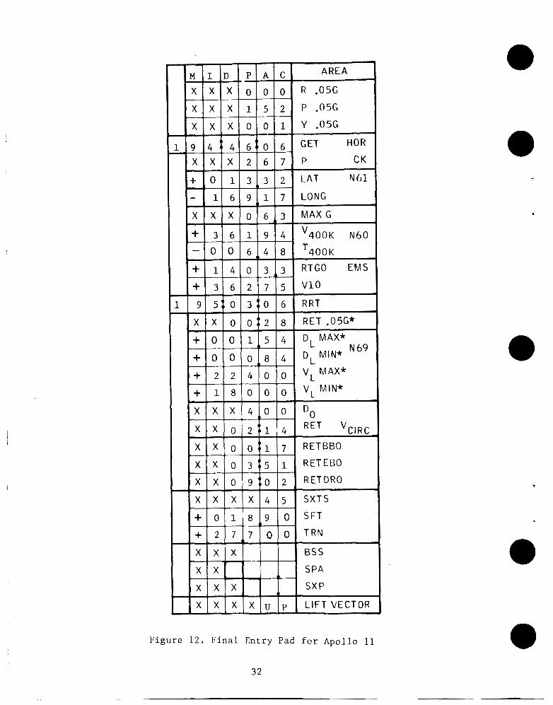
F i g u r e 1 2 . F i n a l Ent ry Pad for A p o l l o 11
32
REFERENCES
1. Task Order for Apollo Lunar Task No. A-220, Amendment
Exploration Program Entry Support. MSC/TRW No. 3, 1 January 1970.
2. Apollo Reentry Simulation Program Engineering Document. TRW Note No. 69-E'MT-777, 10 September 1969.
3. Cole, A . E. and Kantor, A. J.: Air Force Interim Supplemental Atmos- pheres to 90 Kiloirieters. Report No. 153, AFCRL-63-936, December 1963.
33 N A S A - MSC