i ap-4 autopump · page i ap-4 manual table of contents revision 12 - september, 2007 table of...
TRANSCRIPT
OPERATIONS
MANUAL
AutoPump Controllerless System(for 4-inch wells or larger)
AP-4 AutoPump®
Document No. 600006-12
550 Adeline StreetOakland, California 94607
(800) 537-1767 — North America Only(510) 891-0880 — Tele.(510) 444-6789 — Fax
PO Box 37266095 Jackson RoadAnn Arbor, Michigan 48106-3726
(800) 624-2026 — North America Only(734) 995-2547 — Tele.(734) 995-1170 — [email protected] — E-mailwww.qedenv.com
Copyright QED Environmental Systems, September 2007
Environmental Systems
The equipment in this manual is protected under U.S. and foreign patents issued and pending:
U.S. Patents:Selective Oil Skimmer (SOS) 4,497,370Specific Gravity Skimmer (SPG) 4,663,037AutoPump (AP) 5,004,405Specific Gravity Skimmer (SPG) Product Sensing 5,474,685Vacuum/Pressure Hydrocarbon Recovery System 4,761,225SPG PSR technology 5,474,685AP-2 5,641,272Genie System 5,704,772 Canada Patent:Specific Gravity Skimmer (SPG) 1,239,868
"AP" is a Registered Trademark of "QED Environmental Systems""AutoPump" is a Registered Trademark of "QED Environmental Systems""SOS" is a Registered Trademark of "QED Environmental Systems""Genie" is a Registered Trademark of "QED Environmental Systems""SPG" is a Registered Trademark of "QED Environmental Systems"The QED Environmental Systems logo is a Registered Trademark of "QED Environmental Systems"QED Environmental Systems is a Registered Trademark of "QED Environmental Systems"

Page i
AP-4 Manual Table of Contents
Revision 12 - September, 2007
Table of Contents
Introduction_________________________________________________1
Safety ........................................................................................................1
How to Contact QED................................................................................2
Chapter 1: Safety ____________________________________________3
A Partial List of Safety Procedures ..........................................................3
Fire and Explosion Protection ..................................................................4
Personal Protection ...................................................................................4
Spill Protection .........................................................................................4
Chapter 2: Overview _________________________________________5
General Specifications ..............................................................................5
This is How it Works ................................................................................6
Major AutoPump Features........................................................................6
Special Operating Conditions ...................................................................8Cold Weather .....................................................................................8
Actions To Take .................................................................................8Flow induced freezing .......................................................................10The well is under a vacuum...............................................................10Abrasive particles in the well ............................................................10Hard pipe air supply connection to the pump....................................10
Options and Accessories ...........................................................................11

QED Environmental SystemsAP-4 Manual
Page ii
Chapter 3: Equipment________________________________________12
Unpacking.................................................................................................12
Equipment List..........................................................................................12
Tools..........................................................................................................13
Parts List ...................................................................................................13
AP-4 AutoPumps ......................................................................................13Bottom-Loading AP-4/BL ................................................................13Top-Loading AP-4/TL ......................................................................13Specifications.....................................................................................16Component Materials ........................................................................16Performance and Air Use Curves ......................................................16Landfill Pump Configurations ...........................................................16
Landfill Specifications ......................................................................16Component Materials.........................................................................16
Single Stage Filter/Regulator....................................................................18
Hoses and Fittings.....................................................................................19Hose and Tubing Color Code Table...................................................19
Volumes Pumped Per Cycle......................................................................20
Pump Support System...............................................................................20
Chapter 4: Assembly & Installation_____________________________21
Cautions ....................................................................................................21
Compressed Air Supply ............................................................................22
Component Assembly...............................................................................22Quick-Connects/Hose Barbs .............................................................22AutoPump Assembly .........................................................................22
Dry Test.....................................................................................................28
Pump Support System and Hose Bundling Assembly..............................29
AutoPump Installation ..............................................................................34

AP-4 Manual Table of Contents
Revision 12 - September, 2007 Page iii
Chapter 5: Start Up and Operation _____________________________36
Start Up Checklist.....................................................................................36
Observation of System Operation.............................................................37
Downwell Testing of the AutoPump.........................................................37
AutoPump Shutdown while Submerged...................................................37
AutoPump Removal Technique (optional) ...............................................37
Chapter 6: Maintenance ______________________________________38
General Maintenance ................................................................................38
Maintenance Table ....................................................................................39
Air Quality Check.....................................................................................39Single Stage Filter/Regulator Maintenance.......................................39
AutoPump Service ....................................................................................41AutoPump Shutdown and Removal from Well .................................41
For Bottom-loading pumps ................................................................41For Top-loading pumps ......................................................................41
Removing Pump Casing ....................................................................42Cleaning Pump Interior .....................................................................44Iron Build-up Cleaning Procedure.....................................................53Installing Pump Casing .....................................................................54
Cleaning the Pump Cycle Counter ...........................................................55
Checking Volumes Pumped Per Cycle .....................................................55
Chapter 7: Troubleshooting & Repairs __________________________56
Troubleshooting ........................................................................................57
Returning Equipment for Service .............................................................60
Equipment Cleaning Requirements ..........................................................61Hoses and Fittings .............................................................................61AutoPumps ........................................................................................61

QED Environmental SystemsAP-4 Manual
Page iv
Appendix A: Performance Curves_______________________________62
Appendix B: Air Consumption Curves ___________________________84
Appendix C: AP-4 Conversions _________________________________98
Appendix D: Vacuum on Well__________________________________101
Terms, Conditions and Warranty _______________________________106
Figures:
Figure 1 - How it Works..................................................................................... 7
Figure 2 - Overview of the AutoPump System.................................................. 9
Figure 3 - Long, Short and Lowdrawdown Bottom-Loading (AP-4/BL).......... 14
Figure 4 - Long, Short and Lowdrawdown Top-Loading (AP-4/TL) ................ 15
Figure 5 - Long, Short, and LDD Bottom-Loading Leachate (AP-4/BL) ......................................................................................... 17
Figure 6 - Single Stage Filter/Regulator 60 with Quick-Connects .................... 18
Figure 7 - Locking Quick-Connects .................................................................. 23
Figure 8 - Two-Ear Clamp and Hose Barb Assembly Instructions.................... 24
Figure 9 - Worm Drive Clamp and Hose Barb Assembly Instructions.............. 25
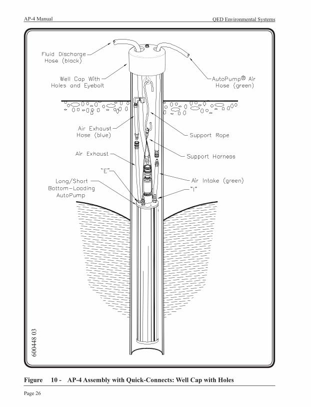
Figure 10 - AP-4 Assembly with Quick-Connects: Well Cap with Holes ........... 26
Figure 11 - AP-4 Assembly: Well Cap with Hose Barbs ..................................... 27
Figure 12 - Examples of Well Caps ..................................................................... 30
Figure 13 - Hose Bundling: Part 1 of 2................................................................ 32
AP-4 Manual Table of Contents
Revision 12 - September, 2007 Page v
Figure 14 - Hose Bundling: Part 2 of 2................................................................ 33
Figure 15 - Removing AP-4 Pump Casing .......................................................... 43
Figure 16 - Exploded View of a Top-Loading AutoPump AP-4 (Long & Short).................................................................................. 45
Figure 17 - Exploded View of a Bottom-Loading AutoPump AP-4 (Long & Short).................................................................................. 46
Figure 18 - Exploded View of AP-4 Lever Assembly.......................................... 47
Figure 19 - Exploded View of LDD Bottom Loading AutoPump AP-4 .............. 48
Figure 20 - Exploded View of LDD Top-Loading AutoPump AP-4.................... 49
Figure 21 - Bottom Intake Plug-Type Check Valve Assembly ............................ 50
Figure 22 - Exploded View of Bottom Intake Radial Check Valve Assembly..... 51
Figure 23 - Exploded View of 1-Inch Brass Check Valve.................................... 52
Figure 24 - Long AP-4/BL Performance Curves: 1-inch I.D. Discharge U.S. UNITS (Includes Leachate Models) ......................................... 64
Figure 25 - Long AP-4/BL Performance Curves: 3/4-inch I.D. Discharge U.S. UNITS (Includes Leachate Models) ......................................... 65
Figure 26 - Long AP-4/BL Performance Curves: 25.4 mm (1-inch) I.D. Discharge METRIC UNITS (Includes Leachate Models) ................................ 66
Figure 27 - Long AP-4/BL Performance Curves: 19 mm (3/4-inch) I.D. Discharge METRIC UNITS (Includes Leachate Models) ................................. 67
Figure 28 - Long AP-4/TL Performance Curves: 1-inch I.D. Discharge U.S. UNITS (Includes Leachate Models) ......................................... 68
Figure 29 - Long AP-4/TL Performance Curves: 3/4-inch I.D. Discharge U.S. UNITS (Includes Leachate Models) ......................................... 69
Figure 30 - Long AP-4/TL Performance Curves: 25.4 mm (1-inch) I.D. Discharge METRIC UNITS (Includes Leachate Models) ................................. 70
Figure 31 - Long AP-4/TL Performance Curves: 19 mm (3/4-inch) I.D. Discharge METRIC UNITS (Includes Leachate Models) ................................ 71
QED Environmental SystemsAP-4 Manual
Page vi
Figure 32 - Short AP-4/BL Performance Curves: 1-inch I.D. Discharge U.S. UNITS (Includes Leachate Models) ......................................... 72
Figure 33 - Short AP-4/BL Performance Curves: 3/4-inch I.D. Discharge U.S. UNITS (Includes Leachate Models) ......................................... 73
Figure 34 - Short AP-4/BL Performance Curves: 25.4 mm (1-inch) I.D. Discharge METRIC UNITS (Includes Leachate Models) ................................. 74
Figure 35 - Short AP-4/BL Performance Curves: 19 mm (3/4-inch) I.D. Discharge METRIC UNITS (Includes Leachate Models) ................................. 75
Figure 36 - Short AP-4/TL Performance Curves: 1-inch I.D. Discharge U.S. UNITS (Includes Leachate Models) ......................................... 76
Figure 37 - Short AP-4/TL Performance Curves: 3/4-inch I.D. Discharge U.S. UNITS (Includes Leachate Models) ......................................... 77
Figure 38 - Short AP-4/TL Performance Curves: 25.4 mm (1-inch) I.D. Discharge METRIC UNITS (Includes Leachate Models) ................................. 78
Figure 39 - Short AP-4/TL Performance Curves: 19 mm (3/4-inch) I.D. Discharge METRIC UNITS (Includes Leachate Models) ................................. 79
Figure 40 - Low Drawdown AP-4/BL Performance Curves: 1-inch (25.4 mm) . I.D. Discharge U.S. and METRIC UNITS ....................................... 80
Figure 41 - Low Drawdown AP-4/BL Performance Curves: 3/4-inch (19 mm) . I.D. Discharge U.S. and METRIC UNITS ....................................... 81
Figure 42 - Low Drawdown AP-4/TL Performance Curves: 1-inch (25.4 mm) I.D. Discharge U.S. and METRIC UNITS .............................................. 82
Figure 43 - Low Drawdown AP-4/TL Performance Curves: 3/4-inch (19 mm).. I.D. Discharge U.S. and METRIC UNITS ....................................... 83
Figure 44 - Long AP-4 Air Consumption Curves: 1-inch I.D. DischargeU.S. UNITS (Includes Leachate Models) ......................................... 86
Figure 45 - Long AP-4 Air Consumption Curves: 3/4-inch I.D. DischargeU.S. UNITS (Includes Leachate Models) ......................................... 87
Figure 46 - Long AP-4 Air Consumption Curves: 25.4 mm (1-inch)I.D. Discharge METRIC UNITS (Includes Leachate Models)......... 88

AP-4 Manual Table of Contents
Revision 12 - September 2007 Page vii
Figure 47 - Long AP-4 Air Consumption Curves: 19 mm (3/4-inch) I.D. Discharge METRIC UNITS (Includes Leachate Models)......... 89
Figure 48 - Short AP-4 Air Consumption Curves: 1-inch I.D. DischargeU.S. UNITS (Includes Leachate Models) ......................................... 90
Figure 49 - Short AP-4 Air Consumption Curves: 3/4-inch I.D. DischargeU.S. UNITS (Includes Leachate Models) ......................................... 91
Figure 50 - Short AP-4 Air Consumption Curves: 25.4 mm (1-inch) I.D. Discharge METRIC UNITS (Includes Leachate Models)......... 92
Figure 51 - Short AP-4 Air Consumption Curves: 19 mm (3/4-inch) I.D. Discharge METRIC UNITS (Includes Leachate Models)......... 93
Figure 52 - Low Drawdown AP-4/BL Air Consumption Curves: 1-inch (25.4 mm) I.D. Discharge U.S. and METRIC UNITS ....................................... 94
Figure 53 - Low Drawdown AP-4/BL Air Consumption Curves: 3/4-inch (19 mm) I.D. Discharge U.S. and METRIC UNITS ....................................... 95
Figure 54 - Low Drawdown AP-4/TL Air Consumption Curves: 1-inch (25.4 mm) I.D. Discharge U.S. and METRIC UNITS ....................................... 96
Figure 55 - Low Drawdown AP-4/TL Air Consumption Curves: 3/4-inch (19 mm) I.D. Discharge U.S. and METRIC UNITS ....................................... 97
Figure 56 - Conversion From Bottom-Loading to Top-Loading AutoPump for pumps made after 1991 ..................................................................... 99
Figure 57 - Conversion From Top-Loading to Bottom-Loading AutoPump for pumps made after 1991 ..................................................................... 100
Figure 58 - AP-4/BL with Vacuum In the Well and Pump Exhaust Outside the Well ................................................................................ 102
Figure 59 - AP-4/BL with Vacuum In the Well and Pump Exhaust In the Well ......................................................................................... 103
Figure 60 - AP-4/TL with Vacuum In the Well and Pump Exhaust Outside the Well ................................................................................ 104
Figure 61 - AP-4/TL with Vacuum In the Well and Pump Exhaust In the Well ......................................................................................... 105

Page 1
AP-4 Manual
Revision 12 – September, 2007
Introduction
Welcome to QED Environmental Systems’ AutoPump® (AP-4) manual.
To ensure the best operator safety and system performance, it is strongly recommended that the operators read this entire manual before using the system.
This manual reflects our many years of experience and includes comments and suggestions from our sales and service personnel and most importantly from our customers. The chapters, their contents and sequence were designed with you, the user and installer, in mind. We wrote this manual so it can be easily understood by users who may not be familiar with systems of this type or are using a QED system for the first time.
Safety
Safety has been a cornerstone of our design which has been proven out in building and shipping systems throughout the world. Our high level of performance is achieved by using quality components, building in redundancies or backup systems, and not compromising our commitment to quality manufacturing. The net result is the highest quality and safest pneumatic pump recovery system on the market. We feel so strongly about safety, based on years of working with the hydrocarbon industry, that it is the first section in all of our manuals.
QED Environmental SystemsAP-4 Manual
Page 2
How to Contact QEDIf for any reason you are unable to find what you need in this manual please feel free to contact the QED Service Department at any time. We encourage you to use following communication methods to reach us at any time:
Service Department QED Environmental Systems www.qedenv.com Oakland Service Center 1133 Seventh Street Oakland, California 94607
(800) 537-1767 – North America Only (510) 891-0880 – Tele. (510) 444-6789 – Fax
Ann Arbor Service Center PO Box 3726 6095 Jackson Road Ann Arbor, Michigan 48106-3726 (800) 624-2026 — North America Only (734) 995-2547 — Tele. (734) 995-1170 — Fax [email protected] — E-mail
QED can be reached 24 hours a day
We welcome your comments and encourage your feedback regarding anything in this manual and the equipment you have on-site.
Thank you again for specifying QED remediation equipment.

Page 3
AP-4 Manual
Revision 12 – September, 2007
Chapter 1: Safety
Safety has been a prime consideration when designing the AutoPump System. Safety guidelines are provided in this manual, and the AutoPump System safety features are listed below. Please do not attempt to circumvent the safety features of this system.
We have also listed some possible hazards involved when applying this system to site remediation. Nothing will protect you as much as understanding the system, the site at which it is being used, and the careful handling of all the equipment and fluids. If you have any questions, please contact the QED Service Department for guidance.
As you read through this manual, you will encounter three kinds of warnings. The following examples indicate how they appear and lists their respective purposes.
Note: Highlights information of interest.Caution: Highlights ways to avoid damaging equipment.WARNING: Highlights personal safety issues.
A Partial List of Safety Procedures
WARNING:The air compressor and any other electrical equipment used with this pneumatic system must be positioned outside of any area considered hazardous because of possible combustible materials.
These safety procedures should be followed at all times when operating QED equipment on or off site, and should be considered as warnings:
• Wear safety goggles when working with the AutoPump System to protect eyes from any splashing or pressure release.
• Wear chemically resistant rubber gloves, boots, and coveralls when handling the AutoPump and fluid discharge hose to avoid skin contact with the fluid being recovered.

QED Environmental SystemsAP-4 Manual
Page 4
• Point all hoses away from personnel and equipment when connecting or disconnecting.
• Always ensure that the fluid discharge hose is connected before the air hose to prevent accidental discharge.
The AutoPump System minimizes the potential for accidents with the following safeguards:
Fire and Explosion Protection
Almost all of QED underground fluid extraction systems are pneumatic. This offers many inherent fire and explosion protection features:
• Compressed air lines eliminates electrical wiring in hazardous areas.
• Aluminum or fiberglass enclosures prevent sparking.
• Standard systems use brass fittings to eliminate sparking hazard.
Personal Protection
On-site, service and maintenance personnel can safely use QED equipment. Safety-in-use is the primary design feature in all systems. Following are some samples:
• All standard high pressure air hoses have automatic shut off quick-connects on the supply side which prevents injury due to hose whip or air blown particles. Tubing does not usually have quick-connect fittings, but is pushed over barbs or pushed into compression fittings.
• Metal regulators and filter bowls are rated at 200 psi and plastic bowls are rated at 150 psi. The metal air filter bowl is made of zinc, providing greater pressure and chemical resistance than plastic bowls and it is less prone to damage if dropped. The customer can choose either material.
Spill Protection
On-site spills cannot always be prevented. QED equipment is designed to take into consideration such unpredictable occurrences that may happen despite strict adherence to standardized safety practices.
• The standard air and fluid hoses are rated at over 800 psi burst pressure to prevent accidental hose breakage.
• Down well quick-connects have locking features to prevent accidental disconnections.
Page 5
AP-4 Manual
Revision 12 – September, 2007
Chapter 2: Overview
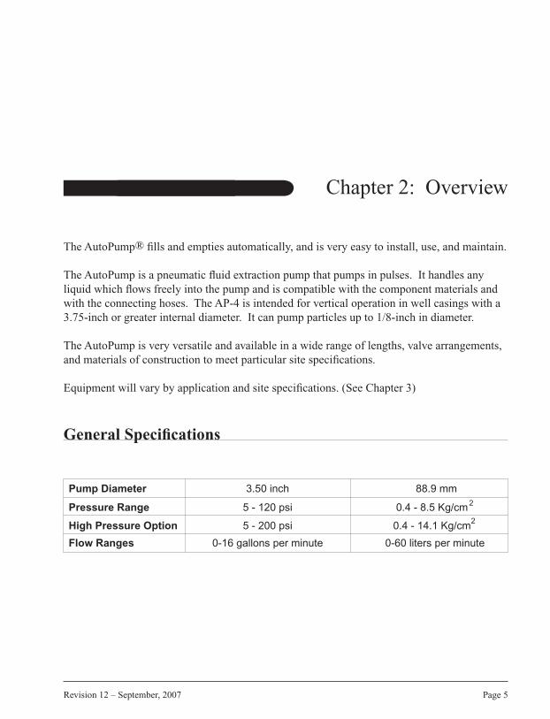
The AutoPump® fills and empties automatically, and is very easy to install, use, and maintain.
The AutoPump is a pneumatic fluid extraction pump that pumps in pulses. It handles any liquid which flows freely into the pump and is compatible with the component materials and with the connecting hoses. The AP-4 is intended for vertical operation in well casings with a 3.75-inch or greater internal diameter. It can pump particles up to 1/8-inch in diameter.
The AutoPump is very versatile and available in a wide range of lengths, valve arrangements, and materials of construction to meet particular site specifications.
Equipment will vary by application and site specifications. (See Chapter 3)
General Specifications
Pump Diameter 3.50 inch 88.9 mm
Pressure Range 5 - 120 psi 0.4 - 8.5 Kg/cm
High Pressure Option 5 - 200 psi 0.4 - 14.1 Kg/cm
Flow Ranges 0-16 gallons per minute 0-60 liters per minute
2
2
QED Environmental SystemsAP-4 Manual
Page 6
This is How it Works
The AutoPump is a submersible compressed air-driven pump which fills and empties automatically. It also controls the fluid level in a well automatically. The pump fills (see Figure 1) when fluids enter either the top or bottom check valve. Air in the pump chamber exits through the exhaust valve as the fluid fills the pump. The float inside the pump is carried upwards by the fluids rising in the casing until it pushes against a stop on the control rod, forcing the valve mechanism to switch to the discharge mode.
The switching of the valve causes the exhaust valve to close and the air inlet valve to open. This causes the pump to empty (see Figure 1) by allowing compressed air to enter the pump. This pressure on the fluid closes the inlet check valve and forces the fluids up the discharge tube and out of the pump through the outlet check valve. As the fluid level falls in the pump, the float moves downwards until it pushes against the lower stop on the control rod, forcing the valve mechanism to switch to the fill mode. The outlet check valve closes and prevents discharged fluids from re-entering the pump. The filling and discharging of the pump continues automatically.
Note: The figures shown here are simplified schematics.
Major AutoPump Features
• The AutoPump System is small and lightweight and can be easily moved from site to site, allowing quick response to changing conditions.
• The hoses are color coded and all the fittings are different so only the proper connections can be made.
• Rugged construction ensures long system life, even under harsh conditions.
• The entire system is pneumatically powered with no electrical components, thus avoiding sparks in control power and sensing devices.
• Durable stainless steel air valves that can pass liquids as viscous as 90 weight gear oil without fouling. The air valves can handle reverse flow and submersion for long periods of time. Unlike pumps with bubblers or bleed hoses, there are no problems with start up, clogging, and failure under these difficult conditions when using the AP-4. This results in less downtime and lower training, maintenance, and repair costs.

Page 7
AP-4 Manual
Revision 12 – September, 2007
Figure 1 - How it Works
6013
45
Chapter 2: Overview

QED Environmental SystemsAP-4 Manual
Page 8
• The AP-4 only uses air while pumping. Unlike systems that rely on bleeding air sensors or timers which pressurize and depressurize the air hoses for each stroke, the air hose for the AP-4 remains pressurized to the pumps at all times. Air compressor power consumption, compressor filter maintenance, and thus operating costs are substantially reduced.
• The AP-4 can be configured to fill from the top or the bottom.
Figure 2 on the next page illustrates an overview of an AutoPump System.
The AP-4 System provides everything required for pumping fluid from a well. QED can also supply the air compressor, if desired.
The system is designed to perform for years and comes with a five year warranty.
Note:An automatic drain on the compressor is highly recommended since it dramatically decreases air filter maintenance. QED can supply an automatic drain.
Caution:Alteration of the System: Do not change or modify the equipment without the expressed written approval of QED.
Special Operating Conditions
Conditions may require adjustment or adaptations to the equipment. Below is a list of some of these conditions, their possible effects, and solutions.
Since every site is different, please contact your QED representative for detailed assistance if needed.
Cold WeatherMoisture in the pneumatic lines can freeze causing problems with the system. Such freezing could result in regulators not reducing the air pressure, valves sticking, and hoses clogging.
Actions To Take
• Use water traps and automatic compressor tank drains. These are available at industrial distributing companies (e.g., W.W. Graingers®).

Page 9
AP-4 Manual
Revision 12 – September, 2007
Figure 2 - Overview of the AutoPump System
6004
42 0
2
Chapter 2: Overview

QED Environmental SystemsAP-4 Manual
Page 10
• Reduce air line freezing by burying air hoses below the frost line, or insulating and heating with heat tape, or running hoses through a PVC pipe with warm air being blown through it.
• Remove all the moisture you can from the air by using drains on the compressor, filter, and low points in the air line. Use an air dryer to lower the dew point of the compressed air below the temperature of exposed lines.
• Protect the air regulator from freezing. During freezing conditions regulators may fail “open”, allowing high pressure (e.g. 150 psi from the compressor) to enter components (e.g. gauges, hoses, fluid receptacles) that may be damaged, cause a safety problem, or release contaminating material.
• Locate the air intake to the compressor so the coolest (driest) air is drawn in. Usually it is better to draw air from outside a building than from the inside.
Flow induced freezingAlthough it rarely occurs, air flow through an AutoPump may cause freezing at water temperatures well above 32˚F, slowing down the system. Cold water, moisture in the compressed air, high air pressure, a high pumping rate, and back pressure on the pump are variables that alone, or in combination with each other, may induce freezing. Should it occur, there are system adaptations which can decrease or eliminate the freezing. Please contact QED for advice.
The well is under a vacuumThe pump will work in a well that is under a vacuum, but there are several conditions that must be considered. (See Appendix D)
Abrasive particles in the wellPlease contact QED service if you encounter problems with abrasives in the well.
Hard pipe air supply connection to the pumpThese can cause debris and scale to travel down to the pump. It can also prevent the pump from cycling smoothly due to a solid connection (non-flexing) to the top of the pump. Blow out all of the hard pipe before connecting the pump. A short (6 feet) length of hose should be used between the hard pipe and the pump to allow the natural movement of the pump to occur without restraint. A small screen filter should be used at the lower end of the metal air pipe to prevent scale from reaching the air valve.

Page 11
AP-4 Manual
Revision 12 – September, 2007
Other site conditions such as highly viscous fluids, extremes of pH, high salinity, deep (>400 feet) applications, high flow rates for LNAPL application, intermittent air supply, high dissolved solids, and high temperature can also be addressed. Please contact QED for guidance.
Options and Accessories
The following options and accessories are available from QED. Contact your QED Representative regarding the following:
• AP Data Module – This water-resistant enclosure protects and shields surface instrumentation from weather and/or harsh site conditions while providing easy visual access to key system instrumentation readings. The options available for inclusion inside the NEMA 3R enclosure are a filter/regulator, pump cycle counter, level sensor regulator and gauge with air flow meter. Also included are a fluid level indicator with an On/Off switch, an Air Inlet Supply Gauge, and a Vacuum/Pressure reference with Gauge.
• Pump Cycle Counter (PCC) – A PCC counts the number of times a pump cycles. The counter provides information for maintenance, service, and statistical purposes with minimal loss in air pressure or performance. A PCC is easily attached on the air inlet hose to the pump.
• Component Materials - Various materials specifically designed to withstand the harsh well environments (e.g. high temperature, abrasives, highly aggressive chemicals, high viscosity) of particular sites are available for all component pieces.
• TFSO – The Tank-Full Shut-Off (TFSO) System is a unique, self-contained pneumatic system that shuts down other pneumatic systems in the event of a liquid level rise or a pressure increase in a container. The TFSO provides dual safety by using two sensors. The system is expandable—the button sensor of the system can be teed to monitor many containers.
• Inlet Conversions – AutoPumps can be converted from Top- to Bottom-Loading and vice versa. See Appendix C for more information.
Chapter 2: Overview
QED Environmental SystemsAP-4 Manual
Page 12
Chapter 3: Equipment
Unpacking
During the unpacking procedure, check for the following:• All parts on the packing list have been included in the box• All fitting openings are unobstructed• The equipment has not been damaged in shipment
Equipment List
The equipment list will vary depending on site specifications, but the following list is a typical configuration:.
1. Top-Loading or Bottom-Loading AP-4 with support harness
2. Single stage filter/regulator with:• 5 micron filter with auto drain trap• Pressure regulator with gauge
3. Pump Cycle Counter (PCC)
4. Hoses:• Fluid discharge hose (black)• System air supply hose (blue)• AutoPump air hose (green)• Air exhaust hose (blue)
Note:Black nylon tubing can be used in place of hose.

Page 13
AP-4 Manual
Revision 12 – September, 2007
5. Pump support system:• Well cap• Polypropylene support rope with quick-link assembly or SS wire rope
(Alternate materials as required)
Tools
The following tools are used to service the AP-4: • Spanner wrench
Parts List
In aggressive sites over millions of cycles, the parts that one may anticipate replacing are:• Discharge check valve ball
AP-4 AutoPumps
In both the Bottom-Loading and the Top-Loading models, the fluid is pushed out of the pump through a check valve located at the top of the pump. This check valve prevents the fluid from reentering the pump.
Bottom-Loading AP-4/BL The Bottom-Loading AutoPump fills through a check valve at the bottom of the pump. There are three lengths of AP-4/BL: long, short, and low drawdown. The fluid level in the well can be drawn down to 36 inches from the bottom of the long BL, and 25 inches from the bottom of the short BL (See Figure 3) and as low as 11.5 inches with the low drawdown configuration (See Figure 5)
Top-Loading AP-4/TL The Top-Loading AutoPump fills through a check valve at the top of the pump, therefore the fluid level in the well will never go below the level of this check valve. There are three lengths of AP-4/TL: long, short (See Figure 4) and low drawdown.
Chapter 3: Equipment

QED Environmental SystemsAP-4 Manual
Page 14
Figure 3 - Long, Short and Low-Drawdown Bottom-Loading (AP-4/BL)

Page 15
AP-4 Manual
Revision 12 – September, 2007
Figure 4 - Long, Short and Low-Drawdown Top-Loading (AP-4/TL)
Chapter 3: Equipment
QED Environmental SystemsAP-4 Manual
Page 16
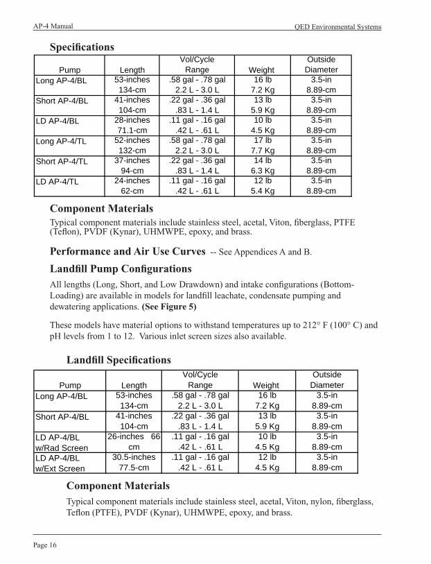
Specifications
Component MaterialsTypical component materials include stainless steel, acetal, Viton, fiberglass, PTFE (Teflon), PVDF (Kynar), UHMWPE, epoxy, and brass.
Performance and Air Use Curves -- See Appendices A and B.
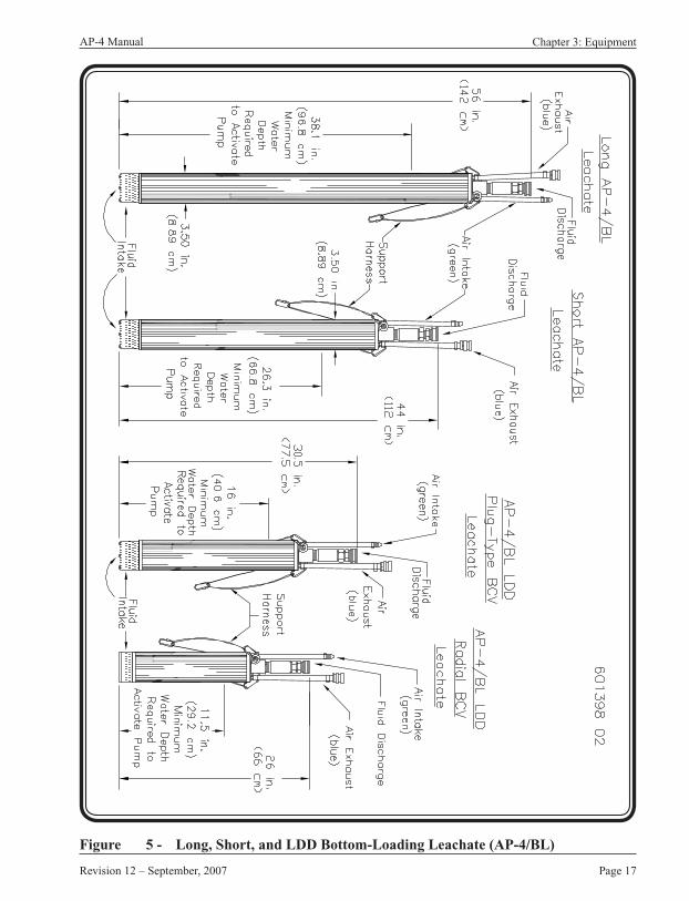
Landfill Pump ConfigurationsAll lengths (Long, Short, and Low Drawdown) and intake configurations (Bottom-Loading) are available in models for landfill leachate, condensate pumping and dewatering applications. (See Figure 5)
These models have material options to withstand temperatures up to 212° F (100° C) and pH levels from 1 to 12. Various inlet screen sizes also available.
Landfill Specifications
Component MaterialsTypical component materials include stainless steel, acetal, Viton, nylon, fiberglass, Teflon (PTFE), PVDF (Kynar), UHMWPE, epoxy, and brass.
Pump LengthVol/Cycle
Range Weight Outside
DiameterLong AP-4/BL 53-inches
134-cm.58 gal - .78 gal
2.2 L - 3.0 L16 lb
7.2 Kg3.5-in
8.89-cmShort AP-4/BL 41-inches
104-cm.22 gal - .36 gal
.83 L - 1.4 L13 lb
5.9 Kg3.5-in
8.89-cmLD AP-4/BL w/Rad Screen
26-inches 66-cm
.11 gal - .16 gal .42 L - .61 L
10 lb 4.5 Kg
3.5-in 8.89-cm
LD AP-4/BL w/Ext Screen
30.5-inches 77.5-cm
.11 gal - .16 gal .42 L - .61 L
12 lb 4.5 Kg
3.5-in 8.89-cm
Pump LengthVol/Cycle
Range Weight Outside
DiameterLong AP-4/BL 53-inches
134-cm.58 gal - .78 gal
2.2 L - 3.0 L16 lb
7.2 Kg3.5-in
8.89-cmShort AP-4/BL 41-inches
104-cm.22 gal - .36 gal
.83 L - 1.4 L13 lb
5.9 Kg3.5-in
8.89-cmLD AP-4/BL 28-inches
71.1-cm.11 gal - .16 gal
.42 L - .61 L10 lb
4.5 Kg3.5-in
8.89-cmLong AP-4/TL 52-inches
132-cm.58 gal - .78 gal
2.2 L - 3.0 L17 lb
7.7 Kg3.5-in
8.89-cmShort AP-4/TL 37-inches
94-cm.22 gal - .36 gal
.83 L - 1.4 L14 lb
6.3 Kg3.5-in
8.89-cmLD AP-4/TL 24-inches
62-cm.11 gal - .16 gal
.42 L - .61 L12 lb
5.4 Kg3.5-in
8.89-cm
Page 17
AP-4 Manual
Revision 12 – September, 2007
Figure 5 - Long, Short, and LDD Bottom-Loading Leachate (AP-4/BL)
Chapter 3: Equipment

QED Environmental SystemsAP-4 Manual
Page 18
Single Stage Filter/Regulator
A single stage 5 micron particulate air filter/regulator has an a manual or an optional automatic drain and is installed on the system air supply hose. The filter/regulator removes particles and some oil vapor, and water droplets from the air passing to the AP-4. The regulator should produce at least as much pressure as required to move the fluid from the depth at which the pump is installed. (See Figure 6)
Note:Too much air pressure can result in low pump efficiency.
Figure 6 - Single Stage Filter/Regulator 60 with Quick-Connects
Page 19
AP-4 Manual
Revision 12 – September, 2007
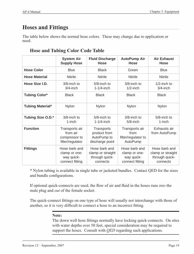
Hoses and Fittings
The table below shows the normal hose colors. These may change due to application or need.
Hose and Tubing Color Code Table
* Nylon tubing is available in single tube or jacketed bundles. Contact QED for the sizes and bundle configurations.
If optional quick-connects are used, the flow of air and fluid in the hoses runs into the male plug and out of the female socket.
The quick-connect fittings on one type of hose will usually not interchange with those of another, so it is very difficult to connect a hose to an incorrect fitting.
Note:The down well hose fittings normally have locking quick-connects. On sites with water depths over 50 feet, special consideration may be required to support the hoses. Consult with QED regarding such applications.
riAmetsySesoHylppuS
egrahcsiDdiulFesoH
riApmuPotuAesoH
tsuahxEriAesoH
roloCesoH eulB kcalB neerG eulB
lairetaMesoH elirtiN elirtiN elirtiN elirtiN
.D.IeziSesoH othcni-8/3hcni-4/3
othcni-8/5hcni-4/1-1
othcni-8/3hcni-2/1
othcni-2/1hcni-4/3
*roloCgnibuT kcalB kcalB kcalB kcalB
*lairetaMgnibuT nolyN nolyN nolyN nolyN
*.D.OeziSgnibuT othcni-8/3hcni-1
othcni-8/5hcni-4/1-1
othcni-8/3hcni-8/5
othcni-8/5hcni-1
noitcnuF riastropsnarTriamorf
otrosserpmocrotaluger/retlif
stropsnarTmorftcudorpotpmuPotuA
tniopegrahcsid
riastropsnarTmorf
otrotaluger/retlifpmuPotuA
riastsuahxEpmuPotuAmorf
sgnittiF dnabrabesoH-enoropmalc
-kciuqyawgnittiftcennoc
dnabrabesoHthgiartsropmalc
-kciuqhguorhtstcennoc
dnabrabesoH-enoropmalc
-kciuqyawgnittiftcennoc
dnabrabesoHthgiartsropmalc
-kciuqhguorhtstcennoc
Chapter 3: Equipment

QED Environmental SystemsAP-4 Manual
Page 20
Volumes Pumped Per Cycle
• The volume of fluid pumped per cycle from an AutoPump varies depending upon the inlet air pressure, the fluid inlet head and the force against which the pump must move the fluid. This force is a sum of the static head and dynamic losses incurred during fluid movement, usually referred to as Total Head.
• The Total Head depends upon back pressure in the surface lines, hose size, fittings, vertical and horizontal pumping distance, the number of pumps feeding the hose system, air pressure to the pump, and the type of pump.
• The effects of some of these variables may cause the volume pumped per cycle to vary from pump to pump on a single site.
Pump Volume per Cycle: Range Volume per Cycle: Typical
Long AP4 0.58 - 0.78 gal (2.2 - 3.0 L) 0.65 gal (2.46 L)
Short AP4 0.22 - 0.36 gal (0.87 - 1.36 L) 0.25 gal (0.95 L)
Low Drawdown AP4 0.11- 0.16 gal (0.42 - 0.61 L) 0.13 gal (0.51 L)
All figures above are dependent on site specific conditions under which the pump is operating
Pump Support System
To safely support the AP-4, a pump support system is offered. Included in the system are a well cap, support rope, and quick-link assembly.(See Figure 13 on page 36, and Figure 14 on page 37)
Well caps with various fitting combinations are available.(See Figure 12 on page 34)
Caution:Although it may be possible to support the pump using only tubing, it is not always wise to do so. If a pump becomes jammed in a well, a strong rope or wire rope separate from the tubing may be needed to withstand the force required to free it. Thus a separate support line is recommended.

Page 21
AP-4 Manual
Revision 12 – September, 2007
Chapter 4: Assembly & Installation
WARNING: PVC pipe is generally not recommended for compressed air service.
Cautions
The following suggestions are offered to reduce the complications involved in assembly and installation.
• Cover the hose ends with tape if they are being pulled through trenches. Be sure the ends of the hoses that connect to the air compressor and fluid discharge have the correct fitting leading out of the well. If you are unsure, look at the respective fittings on the pump.
• Blow out all water and particles from compressed air conduits (trunk lines, sensor hoses, air supply hoses etc.) and fluid lines for at least 10 seconds after the water and particles exit before connecting them to the system.
• When running hoses in conduit, include a rope to pull additional hoses in case they are needed at a later date
• If solid metal piping is used for compressed air conduit, it is advised that an air filter or a “Y” strainer with a fine mesh screen (60 mesh or finer) be placed at the downstream end of the piping. Metal flakes, rust, galvanizing material, dirt, etc. can be dislodged from such metal piping and travel to the pump.

QED Environmental SystemsAP-4 Manual
Page 22
Compressed Air Supply
The AP-4 System includes a compressor-to-pump air line quick disconnect fitting for the compressor.
There is a distinct air inlet on the AP-4; an “I” is stamped next to it on the head of the pump. The air inlet quick connect fitting on the pump has a female counterpart on the air inlet hose. The air inlet must be connected for the AP-4 System to function. Do not lubricate the compressed air coming out of the compressor. The AP-4 does not require lubrication and excess oil may foul the filter/regulator.
WARNING:The compressor should not provide more pressure than the filter can accept. The filter and regulator with plastic bowl accepts a maximum of 150 psi air pressure. The metal bowl can accept 250 psi. Maximum output air pressure setting on the standard regulator is 120 psi. A higher pressure regulator and gauge are optional.
Component Assembly
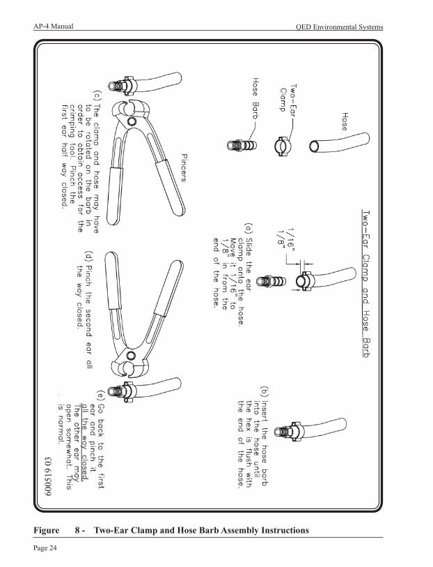
Quick-Connects/Hose BarbsFollow the instructions on Figure 7 for properly securing the locking quick-connects. See Figure 8 and Figure 9 for properly securing hose barbs.
AutoPump AssemblySTEP 1 - Attach Fluid Discharge Hose (black)
Note:If a well cap with holes is used, insert the hoses through the cap before attaching hose.
a. Attach the fluid discharge hose or tubing to the AutoPump. (See Figure 10 and Figure 11)
b. Attach the other end of the discharge hose to the fluid discharge point.

Page 23
AP-4 Manual
Revision 12 – September, 2007
Figure 7 - Locking Quick-Connects
6002
59 0
2
Chapter 4: Assembly & Installation
QED Environmental SystemsAP-4 Manual
Page 24
Figure 8 - Two-Ear Clamp and Hose Barb Assembly Instructions
6005
19 0
3

Page 25
AP-4 Manual
Revision 12 – September, 2007
Figure 9 - Worm Drive Clamp and Hose Barb Assembly Instructions
6005
18 0
2
Chapter 4: Assembly & Installation
QED Environmental SystemsAP-4 Manual
Page 26
Figure 10 - AP-4 Assembly with Quick-Connects: Well Cap with Holes
6004
48 0
3

Page 27
AP-4 Manual
Revision 12 – September, 2007
Figure 11 - AP-4 Assembly: Well Cap with Hose Barbs
6004
49 0
3
Chapter 4: Assembly & Installation

QED Environmental SystemsAP-4 Manual
Page 28
STEP 2 - Attach AutoPump Air Hose (green)
a. If a Pump Cycle Counter (PCC) is used, install it downstream of the air filter regulator and as close to the pump as is reasonable.
b. Attach the AutoPump air hose to the single stage filter/regulator or optional Pump Cycle Counter (See Figure 2 on page 11)
c. Attach the other end of the AutoPump air hose to the AutoPump.
STEP 3 - Attach Air Exhaust Hose (blue)
a. Attach the air exhaust hose to the AutoPump. (See Figure 10 and Figure 11)
STEP 4 - Attach System Air Supply Hose (blue)
a. Thread the air hose socket with 1/4-inch MPT to the compressor. Use Teflon tape or sealant on the threads.
b. Attach the air hose plug end of the system air supply hose to the socket now attached to the compressor.
c. Attach the socket on the discharge end of the hose to the single stage filter/regulator. (See Figure 2 on page 11)
The pump will work in a well that is under vacuum, but there are several conditions that must be considered. (See Appendix D)
Dry Test
Before installing the AutoPump in the recovery well, it is important to test the system for proper operation. Before beginning this test, make sure that all hoses are properly connected as described in the previous section.
To test for float movement and air valve actuation follow these steps:
STEP 1 - Drain all fluid from the pump through the bottom inlet check valve (Bottom-loading) or air inlet fitting (Top-loading).
STEP 2 - Hold the pump horizontally.

Page 29
AP-4 Manual
Revision 12 – September, 2007
STEP 3 - Tip the top of the pump downwards to about 45°. The float should slide to the top of the pump and open the air valve. Air should be heard going into the pump. It will exit the inlet fluid check valve (Bottom-loading) or the outlet check valve (Top-loading).
Caution:If air is not acceptable in the fluid discharge hose, disconnect the hose before performing this test.
STEP 4 - Tip the head of the pump upwards past horizontal to 45° from the vertical. The float should slide to the bottom of the pump and close the air valve.
STEP 5 - Repeat this process 3 or 4 times to ensure the float moves freely and the air-valve opens and closes. If the pump must be tilted nearly vertical before the float slide or the air valve moves, open the pump and inspect for interference.
Pump Support System and Hose Bundling Assembly
A pump support system can be created to support the pump and hoses. The pump support system uses well caps with various fitting combinations. (See Figure 12)
Though it is possible in some instances to support a downwell pump with only the tubing, a separate support line is recommended.
Note:The walls of some wells deform over time. They may trap a downwell pump. In some of those cases the AP-4 support harness and strong support line have proven useful when retrieving the pump.
In addition to supporting the down-well equipment with a support rope, it may be important to support down-well hoses (in most cases nylon tubing does not need to be supported by the support line). Since the down-well hoses can weigh more than the pump, particularly in wells over 50 feet deep with fluid inside the discharge hose, hose support can avoid problems such as kinking, jamming, and breaking.
Chapter 4: Assembly & Installation

QED Environmental SystemsAP-4 Manual
Page 30
Figure 12 - Examples of Well Caps

Page 31
AP-4 Manual
Revision 12 – September, 2007
Hose bundling or the use of jacketed tubing reduces equipment entanglement at the well surface, and aids the removal of the pump from the well. Bundling also assists in positioning the pump and down-well hose assembly against one side of the well casing. Maximum space is created for other items, such as probes, to be periodically placed inside the well.
Follow these instructions to create a hose bundle.
STEP 1 - Lay the equipment on the ground and make all of the necessary hose connections. (See Component Assembly on page 26 and 32)
STEP 2 - If a well cap is supplied, install it on the hoses. (See Figure 10 for well cap with holes; see Figure 11 for well cap with hose barbs)
STEP 3 - Connect the quick-link assembly on the support rope to the eyebolt on the AP-4 and lay the support rope out along with the hoses. Make sure that none of the hoses or support ropes are crossing over each other. (See Figure 13)
Note:To make the next step easier, pull the support rope and the hoses taut.
STEP 4 - Starting at the AutoPump end of the hose, put a tie-wrap through the center of the braided support rope just above the uppermost quick-connect or barb on the AutoPump.
(See Figure 13 and Figure 14)
STEP 5 - Pulling the rope taut, put the tie-wrap around the fluid discharge hose with the rough surface outwards. Cross the ends and complete the figure-8 pattern by securing the ends around the exhaust hose. When you connect the tie-wrap make sure it is straight and is not kinking the hoses. (See Figure 13 and Figure 14)
Note:After completing this step, the fluid discharge hose will be attached to the support rope and the exhaust hose. At this point the air supply hose is still lying free.
STEP 6 - Place the next tie-wrap two feet towards the well cap from the first. Secure the air supply hose rather than the exhaust hose.
Note:It is important to put the tie-wraps approximately two feet apart to keep a proper discharge hose/support rope bundle. Experience has shown that spreading the tie-wraps further apart than two feet increases the probability for hose kinking.
Chapter 4: Assembly & Installation

QED Environmental SystemsAP-4 Manual
Page 32
Figure 13 - Hose Bundling: Part 1 of 2
6004
80 0
3

Page 33
AP-4 Manual
Revision 12 – September, 2007
Figure 14 - Hose Bundling: Part 2 of 2
6004
87 0
3
Chapter 4: Assembly & Installation
QED Environmental SystemsAP-4 Manual
Page 34
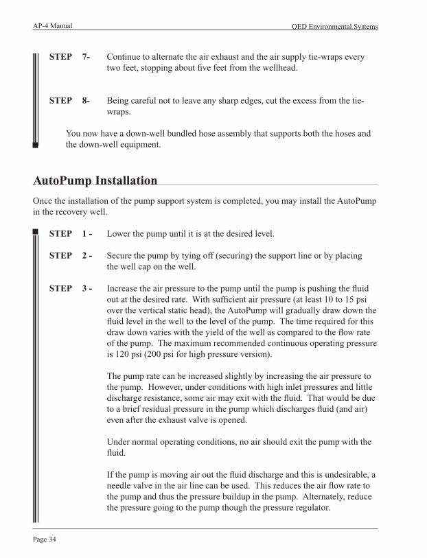
STEP 7- Continue to alternate the air exhaust and the air supply tie-wraps every two feet, stopping about five feet from the wellhead.
STEP 8- Being careful not to leave any sharp edges, cut the excess from the tie-wraps.
You now have a down-well bundled hose assembly that supports both the hoses and the down-well equipment.
AutoPump Installation
Once the installation of the pump support system is completed, you may install the AutoPump in the recovery well.
STEP 1 - Lower the pump until it is at the desired level.
STEP 2 - Secure the pump by tying off (securing) the support line or by placing the well cap on the well.
STEP 3 - Increase the air pressure to the pump until the pump is pushing the fluid out at the desired rate. With sufficient air pressure (at least 10 to 15 psi over the vertical static head), the AutoPump will gradually draw down the fluid level in the well to the level of the pump. The time required for this draw down varies with the yield of the well as compared to the flow rate of the pump. The maximum recommended continuous operating pressure is 120 psi (200 psi for high pressure version).
The pump rate can be increased slightly by increasing the air pressure to the pump. However, under conditions with high inlet pressures and little discharge resistance, some air may exit with the fluid. That would be due to a brief residual pressure in the pump which discharges fluid (and air) even after the exhaust valve is opened.
Under normal operating conditions, no air should exit the pump with the fluid.
If the pump is moving air out the fluid discharge and this is undesirable, a needle valve in the air line can be used. This reduces the air flow rate to the pump and thus the pressure buildup in the pump. Alternately, reduce the pressure going to the pump though the pressure regulator.

Page 35
AP-4 Manual
Revision 12 – September, 2007
Note:Submerging the pump before supplying it with air will result in fluids entering the exhaust hose. Those fluids will be discharged from the exhaust hose during the first few cycles of the pump. If such discharge will not be confined to the well, the operator may wish to install the pump with a low air pressure supplied to the pump. To obtain the value of that low pressure in psi, multiply the number of feet that the pump is to be submerged by one-half (0.5).
WARNING:Be sure that the fluid discharge has a closed valve during such a process because the pump may have enough pressure to begin pumping fluid from the well.
Chapter 4: Assembly & Installation
QED Environmental SystemsAP-4 Manual
Page 36
Chapter 5: Start Up and Operation
Start Up Checklist
In normal operation, the AP-4 System requires little attention.
Before regulating the air pressure to the desired operating pressure, ensure that the following conditions exist:
1. Personal Protective Equipment (PPE) is being used by all personnel.
2. The pump is submerged below the fluid level.
3. All hoses are connected.
4. The exterior air filter is mounted vertically to allow the filter and its bowl drain to operate properly.
5. All out-of-well air and fluid valves are in their correct positions.
6. A method of rapid disconnect and exhaust (or at least a shut off) of compressed air to the pump is available in case of an unexpected occurrence.
7. When pumping is to begin, either gradually raise the air pressure to the pump or gradually open the air valve to the pump to allow the pump and hoses to slowly pressurize. Check for leaks as you do this.
8. As the air pressure overcomes the static and dynamic resistant forces, the pump will begin to cycle. Listen for the periodic exhaust of air from the pump to determine that the pump is working. The pump should push fluid out and then exhaust sharply to fill before pressurizing and pushing the fluid out again.
Cycling can also be monitored by placing an air pressure gauge at the well head and by observing a pulse counter, if one is present.
9. If a pulse cycle counter is installed, it should be adjusted to accomodate the individual well conditions. Refer to the PCC manual, Document # 600473.

Page 37
AP-4 Manual
Revision 12 – September, 2007
Observation of System Operation
Observe the system operation for at least 10 pump cycles to ensure everything is working. If the well influx is low so the pump seldom cycles, pour clean water into the well to check on the pump. If allowed, the pump discharge can be directed into the well so the pump will cycle within an acceptable period to allow for observance of operation. Check your local regulations to determine if these practices are permissible.
Note:The Pump Cycle Counter may have to be readjusted if it is set when the water is recirculating to the well.
After the entire site is operating, return to each well to ensure that the pump and PCCs are functioning properly. The addition of other pumps and possible system back pressure can necessitate air pressure and counter readjustment.
Downwell Testing of the AutoPump
While the AutoPump is in the well, it can be tested by putting compressed air into the exhaust hose of the pump.
Note:The air supply hose must be shut off or pressurized when this is done.
The compressed air will enter the pump through the exhaust valve and push any fluids in the pump up the discharge tube. If sufficient compressed air is continually supplied, it will also exit the discharge tube and cause the fluid in the discharge hose to be airlifted to the surface. This method can be used to lighten the pump and hoses before removing the pump from the well. This process can also show whether the fluid inlet check valve is sealing and if the pump is capable of discharging fluid.
AutoPump Shutdown while Submerged
The AutoPump can be submerged for long periods of time at most sites. If the well environment is such that deposition occurs on stainless steel parts, the operator may wish to raise the pump above the water level during a shutdown of the system.
AutoPump Removal Technique (optional)
By pressurizing the exhaust hose as noted above and airlifting the fluids out of the well, the fluid in an AutoPump and discharge hose can be reduced significantly. This can be used to lighten the system before removing it from the well.
Chapter 5: Start Up and Operation

QED Environmental SystemsAP-4 Manual
Page 38
Chapter 6: Maintenance
General Maintenance
The AP-4 should be relatively free of maintenance. The frequency of maintenance depends upon the nature of the fluids being pumped. Follow these general maintenance checks.
• Periodically inspect all hoses and connections for damage. Make sure that the hoses are not split or cracked, and listen for leaks in the system.
• Even if significant amounts of oil and water enters the air hose, the AP-4 System should perform reliably for years. Check the Air filters and filter bowl drains on the filters/regulator for saturation and operation every few weeks.
• Periodically drain the air filters on the air hose to the pumps of collected particles, water and oil. Draining prevents the filter from clogging up or being otherwise damaged. Check the regulator to ensure the pressure setting has not drifted appreciably.
• An automatic drain on the compressor is highly recommended, since such an addition can dramatically increase air filter life and decrease maintenance. Automatic drains are available from QED.
• The pump can be opened up in the field if the area is clean and dry.
A maintenance video is available from QED.
Page 39
AP-4 Manual
Revision 12 – September, 2007
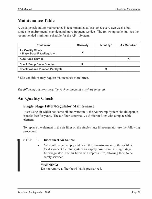
Maintenance Table
A visual check and/or maintenance is recommended at least once every two weeks, but some site environments may demand more frequent service. The following table outlines the recommended minimum schedule for the AP-4 System.
* Site conditions may require maintenance more often.
The following sections describe each maintenance activity in detail.
Air Quality Check
Single Stage Filter/Regulator MaintenanceEven using air which has some oil and water in it, the AutoPump System should operate trouble-free for years. The air filter is normally a 5 micron filter with a replaceable element.
To replace the element in the air filter on the single stage filter/regulator use the following procedure:
STEP 1 - Disconnect Air Source
• Valve off the air supply and drain the downstream air to the air filter. Or disconnect the blue system air supply hose from the single stage filter/regulator. The air filters will depressurize, allowing them to be safely serviced.
WARNING:Do not remove a filter bowl that is pressurized.
X
X
Equipment
Air Quality Check
• Single Stage Filter/Regulator
AutoPump Service
Check Pump Cycle Counter
Check Volume Pumped Per Cycle
Biweekly Monthly* As Required
X
X
Chapter 6: Maintenance

QED Environmental SystemsAP-4 Manual
Page 40
STEP 2 - Remove Filter Bowl
• Different styles of air filters are available. The following instructions are given for the most typical filter used, one with 1/4” pipe thread.
• Remove the bowl of the air filter by sliding the button downward and twisting the bowl about 1/8 of a turn. The bowl should slide downward from the upper portion of the filter revealing the filter element. Unscrew the element as you would unscrew a light bulb. Hand tighten the element after replacing it.
Make sure to replace the correct filter element.
- Blue or black filter bowl: QED Filter element Part No. 205071
- Silver filter bowl: QED Filter element Part No. 205800
STEP 3 - Bowl Drain
Optional Float Drain
• Wash out any deposits and oil buildup from the filter bowl with warm water and soap. To make sure the float drain is operating freely, shake it; the drain should rattle. Test the float drain by filling the bowl with water, assembling the bowl to the filter and reconnecting it to the air supply. The water should drain from the bowl. When under pressure, the drain should not leak.
Standard Manual Drain
• With water in the bowl, open the drain and ensure the liquid drains easily. When under pressure and closed, the drain should not leak.

Page 41
AP-4 Manual
Revision 12 – September, 2007
AutoPump Service
AutoPump Shutdown and Removal from WellTo shut down and remove the AutoPump, follow these directions:
STEP 1 - Wait until the pump is in its discharge cycle and then raise it above the water level in the well. This will empty most of the fluid from the pump making it lighter to lift. There will also be less fluid to drain from the pump.
Note:See Start Up and Operation for optional pump removal technique.
STEP 2 - Pull the pump and hoses to the surface.
STEP 3 - Shut off the air to the pump and disconnect the air hose from the pump.
STEP 4 - Ensure that there is a safe place to drain any fluid from the pump and discharge hose.
STEP 5 - Disconnect the fluid discharge hose from the pump.
For Bottom-loading pumpsDrain the fluid in the pump by lifting the bottom inlet check valve from its seat by using a thin wire or Allen wrench.
For Top-loading pumpsDrain the fluid by turning the pump upside-down and allowing fluid to flow from the air inlet fitting.
Caution:Wear gloves and catch the draining fluid in a sump or bucket.
Chapter 6: Maintenance

QED Environmental SystemsAP-4 Manual
Page 42
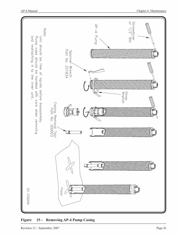
Removing Pump CasingFollow these instructions for removing the pump casing:
Caution:When assembling or disassembling the pump, do not rotate the casing. This action may cause the float and control rod to rotate with the casing. Instead of rotating the casing, spin the bottom check valve (or plug on a Top-Loading pump) and hold the casing stationary.
Caution:After troubleshooting is completed and before assembling the pump, slowly move the float through its range to ensure that the lever will trip, even if the pump fills and empties slowly.
Unscrew the bottom check valve or plug from the discharge tube. (See Figure 15)
STEP 1 - Fit a spanner wrench in one of the holes in the circumference of the lower head. The lower head has right-handed threads, so the direction of rotation for disassembly is counterclockwise if looking at the bottom of the pump.
STEP 2 - Hold the top head of the pump by the support rings.
STEP 3 - Insert a large screw driver through one of the support rings and leverage it against the coupling for the discharge tube.
Caution:Do not press against the air hoses or air hose fittings.
STEP 4 - Turn the plug or check valve.
Caution:Do not leverage the large screwdriver against the air inlet or air exhaust fittings. This could damage the fittings.
Note:The O-rings at the top and bottom of the pump may have swollen due to solvents in the fluid being pumped and therefore make turning the plug or check valve difficult.
Page 43
AP-4 Manual
Revision 12 – September, 2007
Figure 15 - Removing AP-4 Pump Casing
Chapter 6: Maintenance

QED Environmental SystemsAP-4 Manual
Page 44
STEP 5 - If you suspect the pump of being clogged with mud or other particles, prevent the outer casing from turning while the lower plug or check valve is unscrewed.
STEP 6 - Have a second person hold a strap wrench around the pump casing. If there is only one person, hold the upper head in a vise while unscrewing the lower head. This allows a free hand to hold the strap wrench which prevents the pump casing from rotating.
STEP 7 - When the plug or check valve is removed, use a pump casing removal tool to remove the pump casing. The pump casing removal tool is a specially threaded coupling with a pipe extension.
STEP 8 - Thread the coupling onto the bottom of the discharge pipe (onto the same threads from which the lower head was unscrewed).
STEP 9 - Hold the pump vertically upright with the pump casing removal tool extending down out of the pump casing.
STEP 10 - Hold the pump casing and striking the pump casing removal tool on the ground. This will cause the pump casing to slide off the upper O-ring and will allow it to slide off the pump.
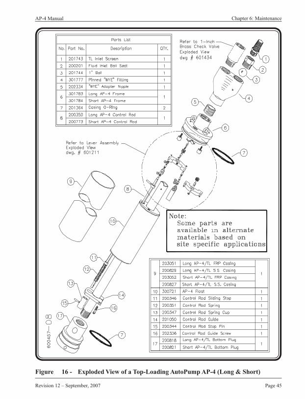
Cleaning Pump InteriorThe inner workings of the pump should now be exposed for inspection and cleaning. (See Figure 16, Figure 17, Figure 18, Figure 19, Figure 20, and Figure 21)
Note:A Scotch Brite® abrasive pad is useful for cleaning debris from the pump components.
STEP 1 - Gently brush off built-up solids from the float, the discharge tube, the pump casing and the control rod guide.
STEP 2 - The pump can be steam cleaned without damage.
STEP 3 - Remove thick deposits of hardened scale on the discharge tube by using a handbrush or by lightly tapping the discharge tube with a small hammer. Be careful not to strike any pins or other components, since they may be damaged.
Page 45
AP-4 Manual
Revision 12 – September, 2007
Figure 16 - Exploded View of a Top-Loading AutoPump AP-4 (Long & Short)
Chapter 6: Maintenance

QED Environmental SystemsAP-4 Manual
Page 46
Figure 17 - Exploded View of a Bottom-Loading AutoPump AP-4 (Long & Short)

Page 47
AP-4 Manual
Revision 12 – September, 2007
Figure 18 - Exploded View of AP-4 Lever Assembly
Chapter 6: Maintenance
QED Environmental SystemsAP-4 Manual
Page 48
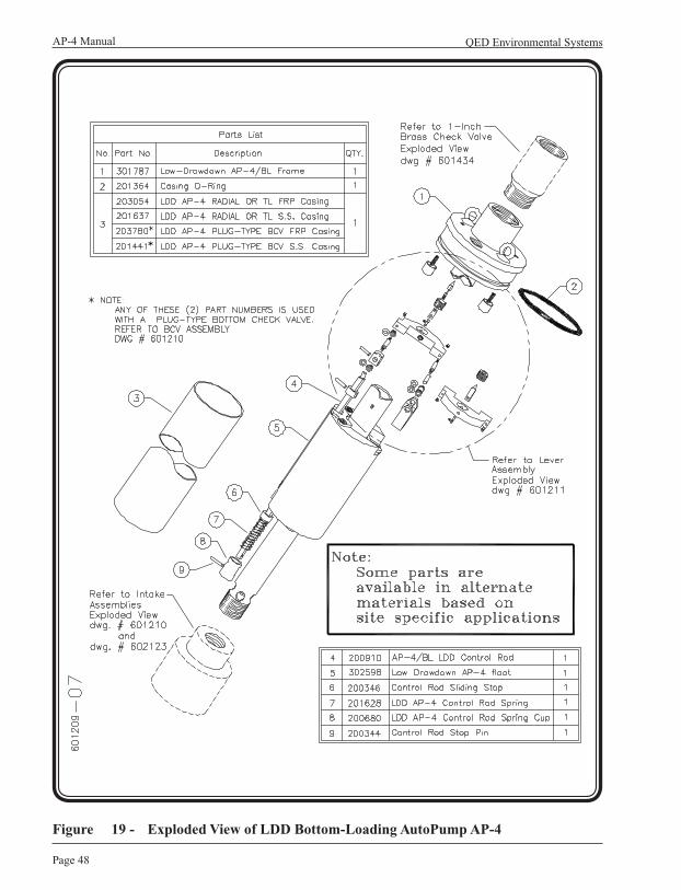
Figure 19 - Exploded View of LDD Bottom-Loading AutoPump AP-4
Page 49
AP-4 Manual
Revision 12 – September, 2007
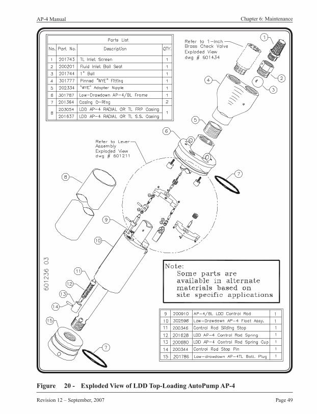
Figure 20 - Exploded View of LDD Top-Loading AutoPump AP-4
Chapter 6: Maintenance

QED Environmental SystemsAP-4 Manual
Page 50
Figure 21 - Bottom Intake Plug-Type Check Valve Assembly
Page 51
AP-4 Manual
Revision 12 – September, 2007
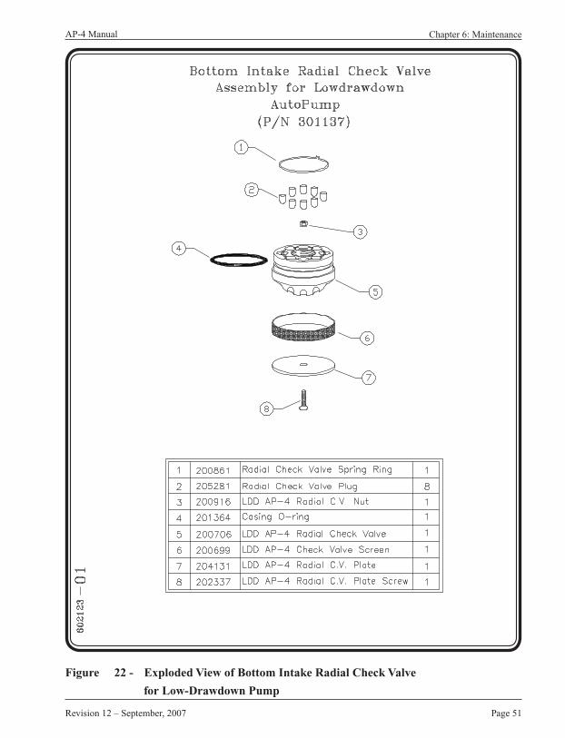
Figure 22 - Exploded View of Bottom Intake Radial Check Valve
Chapter 6: Maintenance
for Low-Drawdown Pump
QED Environmental SystemsAP-4 Manual
Page 52
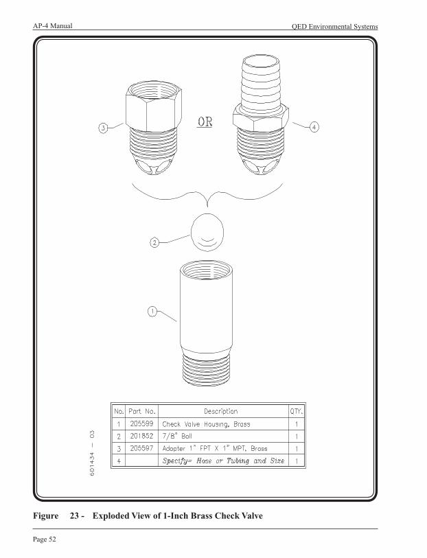
Figure 23 - Exploded View of 1-Inch Brass Check Valve
Page 53
AP-4 Manual
Revision 12 – September, 2007
Chapter 6: Maintenance
Iron Build-up Cleaning ProcedureAfter the casing has been removed from the AutoPump please follow the procedure below:
Note:The procedure described below can be seen in the Maintenance Video Tape. This will aid the technicians understanding and ease of properly disassembling the AutoPump, effectively cleaning components and then re-assembling the AutoPump.
STEP 1 - The bottom intake check valve assembly should be removed from the casing. (See page 49, and Figure 15 on page 50)
STEP 2 - Visually inspect both the 1 inch stainless steel fluid discharge pipe for iron build-up or debris. Also, do the same with the float that rides up and down on the SS discharge pipe.
STEP 3 - Should there be iron deposits on either or both the discharge pipe or float, then remove the float from the SS fluid discharge pipe as follows:
- Remove the control rod guide. (See Figure 16 and Figure 17)- Remove the small SS pin from the bottom spring cup “Stop”. The
Stop is the small white part located just below the Spring identified on Figure 16 and Figure 17. The pin and Stop removal will allow you to remove the spring and float from the SS discharge pipe.
STEP 4 - The 1 inch stainless steel fluid discharge pipe can now be cleaned using either a Scotch Brite pad, a wire brush or finally a wire wheel on either a drill or a grinding machine. After removing the iron debris, it is recommended the pipe be water rinsed.
STEP 5 - Usually the AP-4 float will be one of two types. Most floats have a metal plate on each end. The second type of float has round pins protruding into its center hole, and it does not have metal plates.
Both the internal and external surfaces of the float will generally require cleaning. The material choices include a Scotch Brite pad, and a light grade 150 sandpaper.
For floats with plates: If these plates are removed to ease cleaning, they should be replaced on the same float end from which they came. That is, the plates should maintain their original top and bottom positions.
QED Environmental SystemsAP-4 Manual
Page 54
For floats without plates: A knife may be used to aid in cleaning this float.
STEP 6 - The white plastic square Control Rod is the next component to be cleaned. The control rod is the item that fits through the smaller hole in the float and is adjacent to the SS discharge pipe in the assembled pump. Again, use the Scotch Brite pad or a razor or Exacto knife (not sandpaper).
STEP 7 - The final component to be cleaned is the outer AutoPump casing. Please note you may either have a stainless steel or FRP fiberglass pump casing. The fastest and most effective way to clean out the inside surface of the pump casing is to use a three-stone honing tool. The technique is to move the hone in-and-out a half dozen times or so through each end of the casing. The time for the casing cleaning should take no longer than 5 minutes.
The AutoPump is now ready for re-assembly by following the steps above in reverse order.
Installing Pump Casing STEP 1 - Inspect the O-rings to ensure they are capable of sealing (no discernible
cuts or abrasions).
STEP 2 - Lubricate both inside ends of the casing to a depth of 3/4” with a thin layer of food-grade grease. Ensure that the film reaches the edges of the casing.
STEP 3 - Place the bottom check valve (Bottom Loading Pump) or bottom plug (Top Loading Pump) upright on a clean level surface.
STEP 4 - Pull the casing down over the check valve or plug.
Warning:The pump casing has beveled ends that allow it to slide over the O-rings easily. Keep fingers, hands and other body parts away from these edges as they approach the heads. These edges can pinch when the pump casing is slid over the lower and upper heads.
Page 55
AP-4 Manual
Revision 12 – September, 2007
Chapter 6: Maintenance
STEP 5 - Turn the pump upside down and spin the casing assembly on the discharge tube by hand until the edge of the casing contacts the O-ring on the pump head.
Caution:Be careful to swing the counterweight inside the pump.
STEP 6 - Using a spanner wrench on the bottom fitting, or, a strap wrench on the bottom end of the casing (pump bottom), turn the parts together until the casing just contacts the pump head.
STEP 7 - Turn the bottom check valve or the plug in the reverse direction (counter clockwise) so it is looser by 1/4 turn.
Checking Volumes Pumped Per Cycle
See page 20 for information on the AutoPump volumes pumped per cycle. Ensure that volumes correspond with the previous experience on-site, and with the ranges indicated on page 23. If it doesn’t correspond, then one of the following may exist:
1. The AutoPump is malfunctioning. (See Chapter 7: Troubleshooting & Repair)
2. The Pump Cycle Counter may not be counting correctly. Refer to the Pump Cycle Counter Manual for troubleshooting procedures.
3. Site conditions (e.g. air pressure, discharge head) may have changed substantially.

QED Environmental SystemsAP-4 Manual
Page 56
Chapter 7: Troubleshooting & RepairsProblems may occur and usually can be easily resolved by following these instructions. If, after careful reading and service, you cannot resolve the problem, please contact the QED Environmental Systems (QED) Service Department at (800) 537-1767.
Caution:Wear goggles, gloves, and coveralls when servicing this system.After troubleshooting is completed and before assembling the pump, slowly move the float through its range to ensure that the lever will trip even if the pump fills and empties slowly.
Note:See Chapter 6: Maintenance for disassembly and cleaning instructions.
sesuaCelbissoP smotpmyS
snoitcurtsnIdeliateDtrahCsihtwolloF
gnilcyctonpmuP tub,selcyCpmuProdecudersiemulovegrahcsidonsiereht
egrahcsiddiulfniriA
ylppusriA.1 X X
leveldiulF.2 X
detcirtsertsuahxeriA.3 X X
deggolctelnidiulF.4 X
yrevroelacs,sirbeD.5diulfsuocsiv X X X
sniptaolF.6 X X
raewtovipreveL.7 X X
telnirianisirbeD.8evlav X
evlavkcehcdiulF.9 X
gnimitevlaV.01 X

Page 57
AP-4 Manual
Revision 12 – September, 2007
Troubleshooting
1. Air Supply: • If the air pressure is too low, or if the flow is severely restricted, the pump will not
cycle. Check the flow by inserting the pump air fitting part way into the air line socket. A healthy discharge of air should result.
• If the air pressure exceeds the design limitations of the pump, the pump may fail to cycle, or the exhaust valve may have locked up and cause air to enter the fluid discharge.
2. Fluid Level: • The fluid level must be above the fluid inlet on a Top-Loading pump. On a Bottom-
Loading pump, the fluid must be no lower than 9 inches below the head of the pump.
3. Air Exhaust Restricted: • The exhaust line must not be kinked, plugged, or too small in diameter.
• The air exhaust outlet must be above the fluid level.
• If the air exhausts in the well, the well must be vented to the atmosphere or a functioning vapor recovery line.
• If the air exhausts to the atmosphere (outside the well) and a vacuum is drawn on the well, the pump may fail to fill. In order for the pump to fill under these adverse conditions, the pump must be submerged to make up for the pressure difference between the atmosphere and the partial vacuum in the well.
The pressure difference, expressed as feet of water column (FT. W. C.), is how far the fluid must be above the pump before it can fill.
• See Appendix D if there is a vacuum on the well.
• Ice may be forming on the exhaust valve seat due to the temperature drop that accompanies expansion of compressed air. Restrict the exhaust to lower the expansion rate of the exhaust. Restrict the air inlet hose or lower the pressure to reduce the rate of incoming compressed air. The previous three suggestions may reduce the flow rate from the pump. Submerge the head of the pump, if it is not already submerged. Protect the air lines from low temperatures and freezing by burial or insulation.
QED Environmental SystemsAP-4 Manual
Page 58
4. Fluid Inlet Clogged:• If the fluid inlet screen is clogged with debris, or if a Bottom-Loading pump is on the
bottom of the well, water cannot enter the pump.
5. Debris, Scale, or very Viscous Fluid:• If debris, scale or a very viscous fluid has accumulated inside the pump, the float
may not move freely up and down, or the control rod may not slide easily through the float.
• Clean the float, control rod, and the casing. See Chapter 6 for cleaning instructions.
6. Float Pins: • Determine if any part of the float material itself can contact the discharge
pipe. Move each end of the float back and forth, sideways, to ensure that the pins prevent float contact. Call QED for repair options.
Note:If viscous materials cause continual problems, contact QED for possible solutions.
7. Lever Pivot Wear: • Grasp the center of the lever with thumb and forefinger. Rotate the lever to
horizontal.
• Push up and down, toward and away from the head. Confirm that there is less than 1/32 inch of movement.
• Replace the levers if the pivot hole is worn
8. Debris in Air Inlet Valve: (First check #7-Lever Pivot Wear)• Open the pump. Connect the air supply. Pull the control rod down. Listen to
determine if air leaks through. If so, clean the valve by blowing air or water through it from both ends.
• If air still leaks through the valve with the control rod down, the air-hose must be removed to access the valve inlet to check for debris in the valve or in the hose pigtail.
• Push the rod upwards. If little or no air passes through, remove the air-in hose to access the valve inlet. Blow air through the valve from the poppet side to clear debris from the ball and seat.
Page 59
AP-4 Manual
Revision 12 – September, 2007
Chapter 7: Troubleshooting & Repair
9. Fluid Check Valves: • Open the pump. Hold the pump vertically and pour water into the discharge check
valve. If water flows through, clean the valve.
• Remove the valve and use emery cloth or a very fine sand paper to polish the surface where the ball seats.
• If the pump is a Bottom-Loading design, inspect the seat of the bottom check valve for debris and wear. Clean or replace if necessary.
• If the pump is a Top-Loading design, remove the fluid inlet check valve and inspect the seating surface and the ball for debris and wear.
10. Air Inlet Valve Timing: • (First check lever pivot wear per #7)
• Call the QED Service Department for correct air valve timing for your pump.

QED Environmental SystemsAP-4 Manual
Page 60
Returning Equipment for Service
If the equipment needs to be returned to QED for servicing, please follow these steps:
STEP 1 - Call the QED Service Department and obtain a Return Material Authorization (RMA) number. Please have available the customers contact person’s name, company name and address, phone number, fax number, reason for the return, and the names of the chemicals to which the equipment has been exposed.
STEP 2 - Clean all equipment before shipping. See Equipment Cleaning Requirements at the end of this section.
If the equipment must be cleaned after it arrives at QED, the customer will be charged for the cleaning and disposal of material, if necessary. (Cost can be $200.00 per piece of equipment cleaned.) Drain and dry all equipment after cleaning.
STEP 3 - Package the equipment so that it will not be damaged in shipment. Use bubble pack rather than styrofoam flakes as packing material.
STEP 4 - Ship the equipment via a carrier and service level (i.e., one-day, two-day shipping) in consideration of probable service time and return shipment time.
STEP 5 - It is recommended that such shipments be insured so if the shipment is badly damaged or lost, the customer can replace the equipment at little or no cost.
STEP 6 - Include the contact’s name, company, phone number and RMA number given by QED .
STEP 7 - Write the RMA number on the outside of the packaging so it will be directed immediately to the QED Service Department.

Page 61
AP-4 Manual
Revision 12 – September, 2007
Chapter 7: Troubleshooting & Repair
Equipment Cleaning Requirements
If the equipment is to be shipped to another site or to the factory for service, it needs to be thoroughly cleaned before leaving the site. Cleaning the equipment protects the user (sender), the shipper, and the receiver from dirt and/or contaminants. If the equipment is not cleaned prior to shipping for servicing, it may be severely delayed, refused or the shipper may be charged a cleaning fee. Before packing and shipping, ensure that the equipment is dry inside and out.
The following is a list of equipment and how it should be cleaned prior to shipment.
Hoses and FittingsSTEP 1 - Pump clean water or water with a gentle soap solution (e.g. Dove Dish
Soap) through the pump to remove free product and particles.
STEP 2 - Rinse all soap off of the equipment.
STEP 3 - Soak and rinse the outside of the unit with water to remove loose debris and dirt.
STEP 4 - Steam clean inside and out to remove difficult dirt and contaminants.
Caution:Use low pressure (less than 40 psi) when steam cleaning.
AutoPumpsSTEP 1 - Pump clean water or water with a gentle soap (e.g. Dove Dish Soap)
solution through the pump to remove free product and particles.
STEP 2 - Rinse all soap off of the equipment.
STEP 3 - Soak and rinse the outside of the unit with water to remove loose debris and dirt.
STEP 4 - Steam clean inside and out to remove difficult dirt and contaminants.
Caution:Use low pressure (less than 40 psi) when steam cleaning.

QED Environmental SystemsAP-4 Manual
Page 62
These curves were derived from in-house tests using a pump with average air flow capacity. Flow rates in the field may vary slightly due to temperature, air quality, flow restrictions and minor differences in pump adjustments. Flow rates can be affected due to the natural cooling effect of compressed air expansion. If this cooling effect is lowering the flow rate, decreasing the air pressure to the pump can actually increase the flow rate in some cases. Another way to reduce freezing of water vapor in compressed air is to use an air dryer on the compressed air line.
The following charts show the performance flow rate curves for Long, Short, and Low-Drawdown
Long Bottom and Top-Loading AP-4 AutoPumps (3.5-inch OD).• For US units, see Figures 22, 23, 26, and 27.• For Metric units, see Figures 24, 25, 28, and 29.
Short Bottom and Top-Loading AP-4 AutoPumps (3.5-inch OD).• For US units, see Figures 30, 31, 34, and 35.• For Metric units, see Figures 32, 33, 36, and 37.
Low-Drawdown Bottom and Top-Loading AP-4 AutoPumps (3.5-inch OD).• For US and Metric units, see Figures 38, 39, 40, and 41.
The curves are categorized by pump type, hose size, depth of submergence and air supply pressure. To determine the flow rate a pump will produce, the following information must be known:
1. Pump – Long, Short or Low Dardown; Top- or Bottom-Loading.2. Discharge hose size – 3/4-inch or 1-inch is standard. A larger inside diameter may yield a
higher flow rate. This depends on site conditions.3. Fluid Inlet Submergence – Select the submergence depth of the pump below the fluid
under normal operating conditions.4. Air pressure.
Appendix A: Performance Curves
Page 63
AP-4 Manual
Revision 12 – September, 2007
Appendix A: Performance Curves
Example: A long Bottom-Loading pump with a 1-inch discharge hose and 70 psi supply pressure positioned 100 feet below ground and submerged 6 inches below the fluid will produce about 4.5 gallons per minute (GPM).
The same pump submerged 10 feet below the fluid produces 6 GPM.
Note:These flow rates are only applicable for the designated well head conditions. Any additional resistance from out-of-well equipment (e.g. surface hoses, valves, etc.) will affect the values shown on these curves.
With the previous information, obtain the flow rate by using the following steps:• On the horizontal scale, find the depth in the well at which the pump will be located.• Trace that depth upwards to the line for the air inlet pressure you selected.• Travel horizontally over to the vertical scale and read the flow rate.

QED Environmental SystemsAP-4 Manual
Page 64
Figure 24 - Long AP-4/BL Performance Curves: 1-inch I.D. Discharge U.S. UNITS (Includes Leachate Models)
6012
21 0
2

Page 65
AP-4 Manual
Revision 12 – September, 2007
Appendix A: Performance Curves
Figure 25 - Long AP-4/BL Performance Curves: 3/4-inch I.D. Discharge U.S. UNITS (Includes Leachate Models)
6004
51 0
3

QED Environmental SystemsAP-4 Manual
Page 66
Figure 26 - Long AP-4/BL Performance Curves: 25.4 mm (1-inch) I.D. Discharge METRIC UNITS (Includes Leachate Models)
6012
97 0
2

Page 67
AP-4 Manual
Revision 12 – September, 2007
Appendix A: Performance Curves
Figure 27 - Long AP-4/BL Performance Curves: 19 mm (3/4-inch) I.D. DischargeMETRIC UNITS (Includes Leachate Models)
6012
96 0
2

QED Environmental SystemsAP-4 Manual
Page 68
Figure 28 - Long AP-4/TL Performance Curves: 1-inch I.D. Discharge U.S. UNITS (Includes Leachate Models)
6012
23 0
2

Page 69
AP-4 Manual
Revision 12 – September, 2007
Appendix A: Performance Curves
6004
53 0
3
Figure 29 - Long AP-4/TL Performance Curves: 3/4-inch I.D. Discharge U.S. UNITS (Includes Leachate Models)

QED Environmental SystemsAP-4 Manual
Page 70
Figure 30 - Long AP-4/TL Performance Curves: 25.4 mm (1-inch) I.D. Discharge METRIC UNITS (Includes Leachate Models)
6013
05 0
2

Page 71
AP-4 Manual
Revision 12 – September, 2007
Appendix A: Performance Curves
Figure 31 - Long AP-4/TL Performance Curves: 19 mm (3/4-inch) I.D. Discharge METRIC UNITS (Includes Leachate Models)
6013
04 0
2
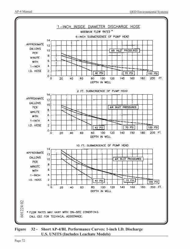
QED Environmental SystemsAP-4 Manual
Page 72
Figure 32 - Short AP-4/BL Performance Curves: 1-inch I.D. Discharge U.S. UNITS (Includes Leachate Models)
6012
24 0
2

Page 73
AP-4 Manual
Revision 12 – September, 2007
Appendix A: Performance Curves
Figure 33 - Short AP-4/BL Performance Curves: 3/4-inch I.D. Discharge U.S. UNITS (Includes Leachate Models)
6004
52 0
3

QED Environmental SystemsAP-4 Manual
Page 74
6013
01 0
2
Figure 34 - Short AP-4/BL Performance Curves: 25.4 mm (1-inch) I.D. Discharge METRIC UNITS (Includes Leachate Models)

Page 75
AP-4 Manual
Revision 12 – September, 2007
Appendix A: Performance Curves
Figure 35 - Short AP-4/BL Performance Curves: 19 mm (3/4-inch) I.D. Discharge METRIC UNITS (Includes Leachate Models)
6013
00 0
2
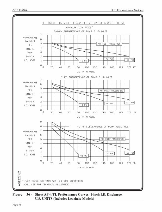
QED Environmental SystemsAP-4 Manual
Page 76
Figure 36 - Short AP-4/TL Performance Curves: 1-inch I.D. Discharge U.S. UNITS (Includes Leachate Models)
6012
22 0
2

Page 77
AP-4 Manual
Revision 12 – September, 2007
Appendix A: Performance Curves
Figure 37 - Short AP-4/TL Performance Curves: 3/4-inch I.D. Discharge U.S. UNITS (Includes Leachate Models)
6004
54 0
3
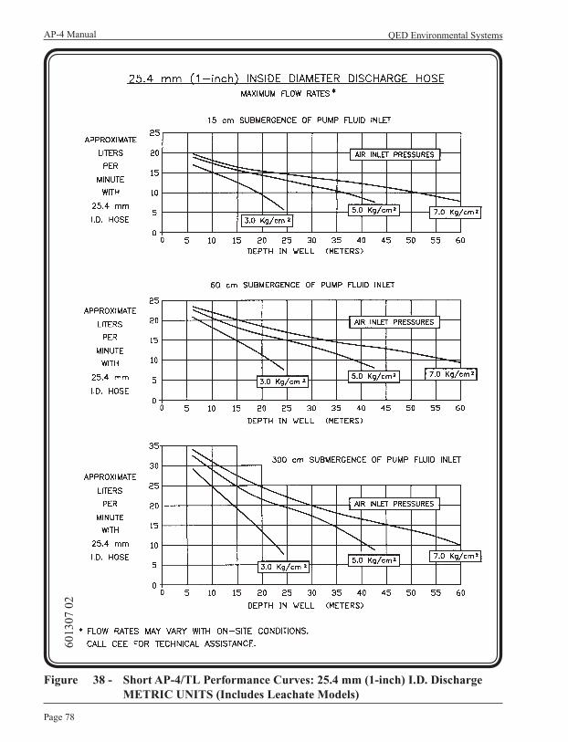
QED Environmental SystemsAP-4 Manual
Page 78
Figure 38 - Short AP-4/TL Performance Curves: 25.4 mm (1-inch) I.D. Discharge METRIC UNITS (Includes Leachate Models)
6013
07 0
2
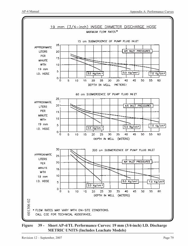
Page 79
AP-4 Manual
Revision 12 – September, 2007
Appendix A: Performance Curves
Figure 39 - Short AP-4/TL Performance Curves: 19 mm (3/4-inch) I.D. Discharge METRIC UNITS (Includes Leachate Models)
6013
06 0
2

QED Environmental SystemsAP-4 Manual
Page 80
Figure 40 - Low Drawdown AP-4/BL Performance Curves: 1-inch (25.4 mm) I.D. Discharge US and METRIC UNITS
6017
37 0
1
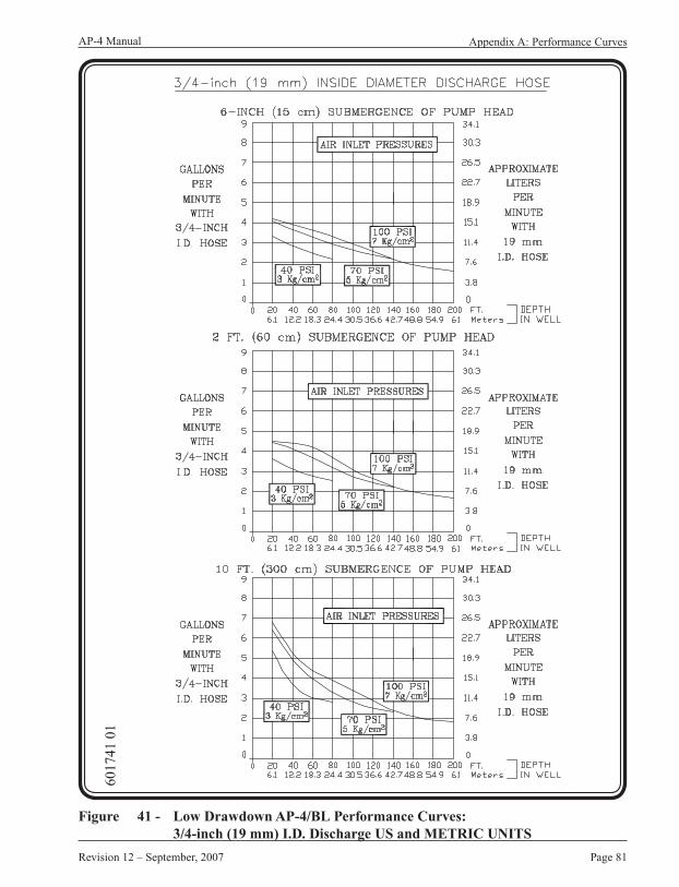
Page 81
AP-4 Manual
Revision 12 – September, 2007
Appendix A: Performance Curves
Figure 41 - Low Drawdown AP-4/BL Performance Curves: 3/4-inch (19 mm) I.D. Discharge US and METRIC UNITS
6017
41 0
1

QED Environmental SystemsAP-4 Manual
Page 82
Figure 42 - Low Drawdown AP-4/TL Performance Curves: 1-inch (25.4 mm) I.D. Discharge US and METRIC UNITS
6017
39 0
1
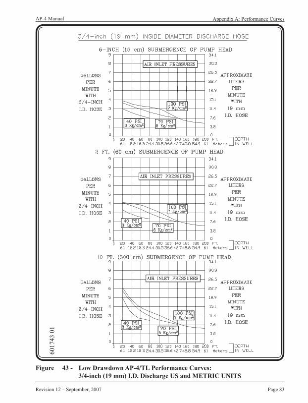
Page 83
AP-4 Manual
Revision 12 – September, 2007
Appendix A: Performance Curves
Figure 43 - Low Drawdown AP-4/TL Performance Curves: 3/4-inch (19 mm) I.D. Discharge US and METRIC UNITS
6017
43 0
1
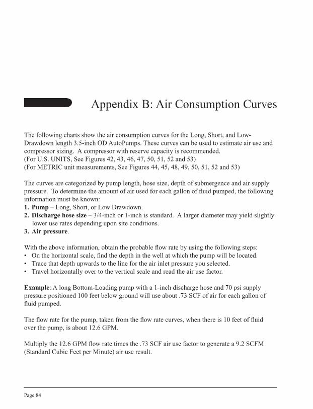
QED Environmental SystemsAP-4 Manual
Page 84
The following charts show the air consumption curves for the Long, Short, and Low-Drawdown length 3.5-inch OD AutoPumps. These curves can be used to estimate air use and compressor sizing. A compressor with reserve capacity is recommended.(For U.S. UNITS, See Figures 42, 43, 46, 47, 50, 51, 52 and 53)(For METRIC unit measurements, See Figures 44, 45, 48, 49, 50, 51, 52 and 53)
The curves are categorized by pump length, hose size, depth of submergence and air supply pressure. To determine the amount of air used for each gallon of fluid pumped, the following information must be known:1. Pump – Long, Short, or Low Drawdown.2. Discharge hose size – 3/4-inch or 1-inch is standard. A larger diameter may yield slightly
lower use rates depending upon site conditions.3. Air pressure.
With the above information, obtain the probable flow rate by using the following steps:• On the horizontal scale, find the depth in the well at which the pump will be located.• Trace that depth upwards to the line for the air inlet pressure you selected.• Travel horizontally over to the vertical scale and read the air use factor.
Example: A long Bottom-Loading pump with a 1-inch discharge hose and 70 psi supply pressure positioned 100 feet below ground will use about .73 SCF of air for each gallon of fluid pumped.
The flow rate for the pump, taken from the flow rate curves, when there is 10 feet of fluid over the pump, is about 12.6 GPM.
Multiply the 12.6 GPM flow rate times the .73 SCF air use factor to generate a 9.2 SCFM (Standard Cubic Feet per Minute) air use result.
Appendix B: Air Consumption Curves

Page 85
AP-4 Manual
Revision 12 – September, 2007
Appendix B: Air Consumption Curves
If the yield of the well is less than the maximum pump rate predicted by the appropriate flow rate graph, multiply the actual fluid recovery rate times the air use factor. This air use can be diminished if the regulator pressure is reduced. The maximum pump rate for the lower air pressure can be predicted using the performance curves.
Note:These air use factors are only applicable for the designated well head conditions. Any additional resistance from out-of-well equipment (e.g. surface hoses, valves, etc.) will affect the factors shown on these curves.

QED Environmental SystemsAP-4 Manual
Page 86
Figure 44 - Long AP-4 Air Consumption Curves: 1-inch I.D. DischargeU.S. UNITS (Includes Leachate Models)
6012
25 0
2

Page 87
AP-4 Manual
Revision 12 – September, 2007
Appendix B: Air Consumption Curves
Figure 45 - Long AP-4 Air Consumption Curves: 3/4-inch I.D. DischargeU.S. UNITS (Includes Leachate Models)
6005
14 0
3

QED Environmental SystemsAP-4 Manual
Page 88
Figure 46 - Long AP-4 Air Consumption Curves: 25.4 mm (1-inch)I.D. Discharge METRIC UNITS (Includes Leachate Models)
6012
99 0
2

Page 89
AP-4 Manual
Revision 12 – September, 2007
Appendix B: Air Consumption Curves
Figure 47 - Long AP-4 Air Consumption Curves: 19 mm (3/4-inch) I.D. Discharge METRIC UNITS (Includes Leachate Models)
6012
98 0
2

QED Environmental SystemsAP-4 Manual
Page 90
Figure 48 - Short AP-4 Air Consumption Curves: 1-inch I.D. DischargeU.S. UNITS (Includes Leachate Models)
6012
26 0
2
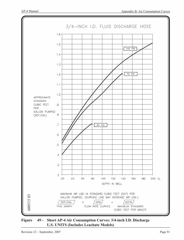
Page 91
AP-4 Manual
Revision 12 – September, 2007
Appendix B: Air Consumption Curves
Figure 49 - Short AP-4 Air Consumption Curves: 3/4-inch I.D. DischargeU.S. UNITS (Includes Leachate Models)
6005
15 0
3

QED Environmental SystemsAP-4 Manual
Page 92
Figure 50 - Short AP-4 Air Consumption Curves: 25.4 mm (1-inch) I.D. Discharge METRIC UNITS (Includes Leachate Models)
6013
03 0
2
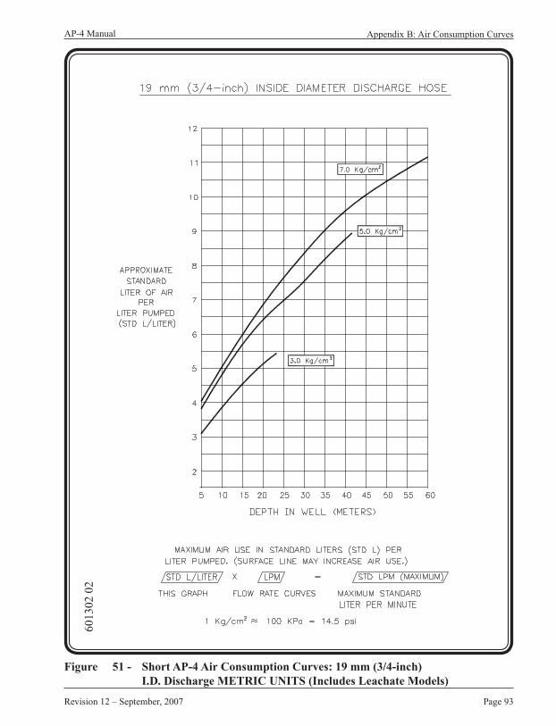
Page 93
AP-4 Manual
Revision 12 – September, 2007
Appendix B: Air Consumption Curves
Figure 51 - Short AP-4 Air Consumption Curves: 19 mm (3/4-inch) I.D. Discharge METRIC UNITS (Includes Leachate Models)
6013
02 0
2

QED Environmental SystemsAP-4 Manual
Page 94
Figure 52 - Low Drawdown AP-4/BL Air Consumption Curves: 1-inch (25.4 mm) I.D. Discharge US and METRIC UNITS
6017
38 0
1

Page 95
AP-4 Manual
Revision 12 – September, 2007
Appendix B: Air Consumption Curves
Figure 53 - Low Drawdown AP-4/BL Air Consumption Curves: 3/4-inch (19 mm) I.D. Discharge US and METRIC UNITS
6017
42 0
1

QED Environmental SystemsAP-4 Manual
Page 96
Figure 54 - Low Drawdown AP-4/TL Air Consumption Curves: 1-inch (25.4 mm) I.D. Discharge US and METRIC UNITS
6017
40 0
1

Page 97
AP-4 Manual
Revision 12 – September, 2007
Appendix B: Air Consumption Curves
Figure 55 - Low Drawdown AP-4/TL Air Consumption Curves: 3/4-inch (19 mm) I.D. Discharge US and METRIC UNITS
6017
44 0
1
QED Environmental SystemsAP-4 Manual
Page 98
Appendix C: AP-4 Conversions
The AP-4 can be converted the from Top- to Bottom-loading or Bottom- to Top-loading by rearranging the check valves.
Pumps produced prior to 1992Top-loading to Bottom-loading conversions:
STEP 1 - Remove the inlet “Y” fitting at the top and move the inlet check valve and its inlet screen to the bottom of the pump.
STEP 2 - The outlet check valve is attached directly to the top of the export tube of the pump via a 1" coupling.
Convert a Bottom-loading pump to a Top-loading pump in the opposite manner.
Pumps produced in 1992 and afterTop-loading to a Bottom-loading conversion:
STEP 1 - Remove the inlet “Y” fitting at the top and install the outlet check valve in a coupling to the top of the export tube at the top of the pump. The inlet check valve must be obtained from QED.
STEP 2 - This inlet check valve replaces the blanked fitting at the bottom of a Top-loading pump.
Convert a Bottom-loading pump to a Top-loading pump in the opposite manner. (See Figure 54 and 55)
Note:When changing short pumps, change the outer casing as well. The casing for the short Top-loading pump is about 3 inches shorter than the case for long Top-loading pump.
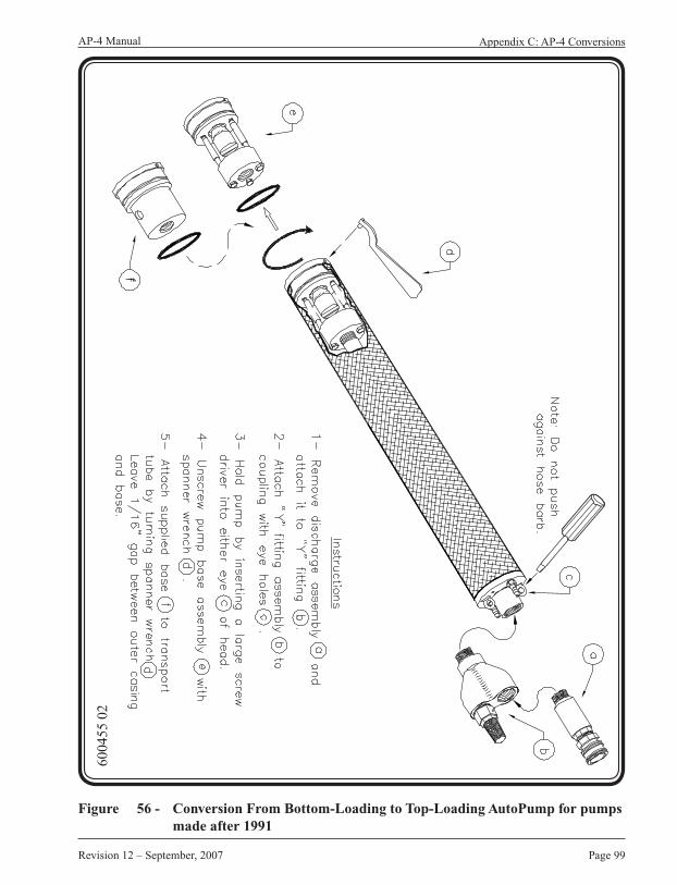
Page 99
AP-4 Manual Appendix C: AP-4 Conversions
Revision 12 – September, 2007
Figure 56 - Conversion From Bottom-Loading to Top-Loading AutoPump for pumps made after 1991
6004
55 0
2

QED Environmental SystemsAP-4 Manual
Page 100
Figure 57 - Conversion From Top-Loading to Bottom-Loading AutoPump for pumps made after 1991
6004
56 0
2
Page 101
AP-4 Manual
Revision 12 - September, 2007
Appendix D: Vacuum on Well
Appendix D: Vacuum on Well
The AP-4 will work in a well that is under vacuum, but there are several conditions that must be considered. These conditions are described in Figure 57, Figure 58, Figure 59, and Figure 60 on the following pages.
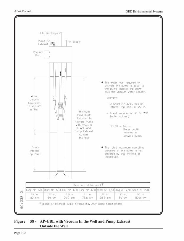
QED Environmental SystemsAP-4 Manual
Page 102
Figure 58 - AP-4/BL with Vacuum In the Well and Pump Exhaust Outside the Well
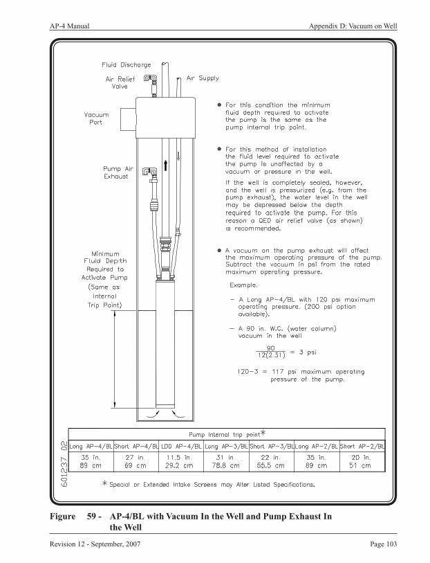
Page 103
AP-4 Manual
Revision 12 - September, 2007
Appendix D: Vacuum on Well
Figure 59 - AP-4/BL with Vacuum In the Well and Pump Exhaust In the Well

QED Environmental SystemsAP-4 Manual
Page 104
Figure 60 - AP-4/TL with Vacuum In the Well and Pump Exhaust Outside the Well
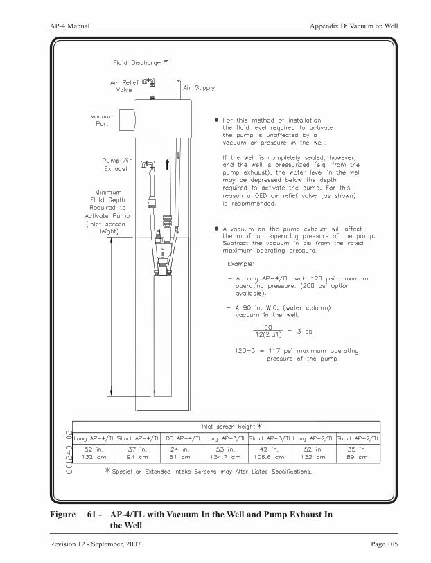
Page 105
AP-4 Manual
Revision 12 - September, 2007
Appendix D: Vacuum on Well
Figure 61 - AP-4/TL with Vacuum In the Well and Pump Exhaust In the Well
QED Environmental SystemsAP-4 Manual
Page 106
Terms, Conditions, and Warranty
Five Year WarrantyThis limited warranty is in lieu of and excludes all other representations made by advertisements, distributors, agents, or manufacturers sales representatives, and all other warranties, both express and implied. There are no implied warranties of merchantability or of fitness for a particular purpose for goods covered hereunder.
QED Environmental Systems warrants to the purchaser of its products that, subject to the limitations and conditions provided within the Terms & Conditions of Sale, products, materials and/or workmanship shall reasonably conform to descriptions of the products and shall be free of defects in material and workmanship.
All warranty durations are calculated from the original date of purchase—determined as beginning the date of shipment from QED facilities and the date QED is notified of a warranty claim. This warranty shall be limited to the duration and conditions set forth below.
1. AP-4 AutoPumps — warranted for five (5) years: 100% material and 100% workmanship for the first three (3) years; 50% material and 50% workmanship for the fourth (4th) and fifth (5th) years. This limited warranty coverage only applies to AP-4 AutoPumps purchased with this warranty. There will be no warranty for application or material compatibility. The materials used in pumps vary depending upon application and the customer is responsible for knowing the environment in which the pump will be operating and working with QED to determine what materials of construction will be best for the application.
The warranty is valid when the following conditions exist: when the site has a pH between 4 and 9, has a salinity of 3500 ppm or less, is between 40 and 120 degrees Fahrenheit, is non-corrosive to the construction materials of the pump; and is not abrasive. Typical commercial fuels are acceptable materials in free or dissolved phase. The pumps and accessories must be operated within the specifications and limits given in the manual for the particular piece of equipment.

Page 107
AP-4 Manual
Revision 12 – September, 2007
2. Pumps, hose, tubing, fittings, heater, condensers and air filtration housings — warranted for one (1) year: 100% material and 100% workmanship. This does not include AP-4 AutoPumps. There will be no warranty for application or material compatibility. The materials used vary depending upon application and the customer is responsible for knowing the environment in which the equipment will be operating and working with QED to determine what materials of construction will be best for the application.
3. Pneumatic Data Modules / Logic Control Panels — warranted for one (1) year: 100% material and 100% workmanship.
4. Parts and Repairs — warranted for ninety (90) days: 100% material and 100% workmanship; when repairs are performed by QED or its appointed agent; from date of repair or for the full term of the original warranty, whichever is longer. Separately sold parts are warranted for ninety (90) days: 100% materials and 100% workmanship.
This warranty will be void in the event of unauthorized disassembly of component assemblies. Defects in any equipment that result from abuse, operation in any manner outside the recommended procedures, use and applications other than for intended use or exposure to chemical or physical environments beyond the designated limits of materials and construction, will also void the warranty.
Chemical attack by liquids and/or abrasive substances contacting equipment and accessories shall not be covered by this warranty. A range of materials of construction is available from QED and it is the Buyer’s responsibility to select materials of construction to fit the Buyer’s application. QED will only warrant that the supplied site liquid contacting materials will conform to published QED specifications and generally accepted standards for that particular material.
QED Environmental Systems shall be released from all obligations under all warranties if any product covered hereby is repaired or modified by persons other than QED service personnel (unless such repair by others is made with the written consent of QED); resold to other parties; and/or moved to or used on a remediation site other than originally specified.
QED Environmental SystemsAP-4 Manual
Page 108
It is understood and agreed that QED Environmental Systems shall in no event be liable for incidental or consequential damages resulting from its breach of any of the terms of this agreement, nor for special damages, nor for improper selection of any product described or referred to for a particular application. Liability under this warranty is limited to repair or replacement F.O.B. QED’s factory, or its appointed agent’s shop, of any parts which prove to be defective within the duration and conditions set forth herein, or repayment of the purchase price at the option of QED, provided the products have been returned in accordance with the duration and conditions set forth herein.
Subassemblies and Other Equipment Manufactured by OthersThe foregoing warranty does not apply to major subassemblies and other equipment, accessories, and other parts manufactured by others, and such other parts, accessories, and equipment are subject only to the warranties, if any, supplied by their respective manufacturers. QED makes no warranty concerning products or accessories not manufactured by QED. In the event of failure of any such product or accessory, QED will give reasonable assistance to Buyer in obtaining from the respective manufacturer whatever adjustment is reasonable in light of the manufacturer’s own warranty.
Illustrations and DrawingsReasonable Effort has been made to have all illustrations and drawings accurately represent the product(s) as it actually was at the time of doing the illustrations and drawings.
However, products may change to meet user requirements and therefore may not be reflected in the literature. In addition, literature may be updated to reflect the most recent equipment revision(s). Changes to either or both equipment and/or literature can be made without notice.
Buyer’s RemediesThe buyer’s exclusive and sole remedy on account of or in respect to the furnishing of defective material or workmanship shall be to secure replacement thereof as aforesaid. QED shall not in any event be liable for the cost of any labor expended on any such product or material or for any special, direct, indirect or consequential damages to any one by reason of the fact that it shall have been deemed defective or a breach of said warranty.
Changes without NoticePrices and Specifications are subject to change without notice.
Shipping DatesShipping dates are approximate and are subject to delays beyond our control.
Page 109
AP-4 Manual
Revision 12 – September, 2007
F.O.B. Point and TitleAll material is sold F.O.B. factory. Title to all merchandise sold shall pass to Buyer upon delivery by Seller to carrier at factory. All freight insurance is the responsibility of the Buyer and shall be charged to the Buyer on the invoice unless directed in writing. All Freight claims are the Buyer’s responsibility.
TermsPayment terms are Net 30 days; 1.5% per month past due.
State and Local TaxesAny taxes, duties or fees which the seller may be required to pay or collect upon or with respect to the sale, purchase, delivery, use or consumption of any of the material covered hereby shall be for the account of the Buyer and shall be added to the purchase price.
AcceptanceAll orders shall be subject to the terms and conditions contained or referred to in the Seller’s quotation, acknowledgments, and to those listed here and to no others whatsoever. No waiver, alteration or modification of these terms and conditions shall be binding unless in writing and signed by an executive officer of the Seller. All orders subject to written acceptance by QED Environmental Systems, Ann Arbor, MI, U.S.A.
Warranty Claims Procedure (Responsibility of purchaser)The original purchaser’s sole responsibility in the instance of a warranty claim shall be to notify QED or its appointed agent, of the defect, malfunction, or other manner in which the terms of this warranty are believed to be violated. The purchaser may secure performance of obligations hereunder by contacting the Customer Service Department of QED or its appointed agent, and:
1. Identifying the product involved by model or serial number, or other sufficient description, that will allow QED, or its appointed agent, to determine which product is defective.
2. Specifying where, when, and from whom the product was purchased.
3. Describing the nature of the defect or malfunction covered by this warranty.

QED Environmental SystemsAP-4 Manual
Page 110
4. After obtaining authorization from QED, sending the malfunctioning component via a RMA# (Return Material Authorization number) to the address below or to its appointed agent:
QED Environmental Systems1133 Seventh StreetOakland, CA 94607USA
(800) 537-1767 Toll-Free in North America(510) 891-0880 (510) 444-6789 FAX
5. Equipment must be cleaned before shipment or it will be cleaned by QED before any work is performed. The customer will be charged for such cleaning.
If any product covered hereby is actually defective within the terms of this warranty, purchaser must contact QED, or its appointed agent, for determination of warranty coverage. If the return of a component is determined to be necessary, QED, or its appointed agent, will authorize the return of the component at Purchasers expense. If the product proves not to be defective within the terms of this warranty, then all costs and expenses in connection with the processing of the Purchaser’s claim and all costs for repair, parts, labor, and shipping and handling, as authorized by owner hereunder, shall be borne by the Purchaser. In no event shall such allegedly defective products be returned to QED, or its appointed agent, without its consent, and QED’s, or its appointed agent’s, obligations of repair, replacement or refund are conditional upon the buyer’s return of the defective product to QED, or its appointed agent. All equipment returned to QED will be appropriately cleaned of contamination before shipping.