i-deas workflows in nx presented by mike morse technical marketing
TRANSCRIPT

I-deas Workflows in NX
Presented by Mike Morse
Technical Marketing

I-deas Workflows in NX 6
Question:
How many of my familiar I-deas modeling, assembly, and PMI functions and workflows are available in NX?
Answer:
Question:
Do I have to abandon my I-deas “Best Practices” and learn a complete new set for NX?
Answer:

I-deas Workflows in NX 6
I-deas ≠ NX NX ≠ I-deas
Major Differences: Interface
Fixed vs. Flexible Units
SI Units vs. Metric / English History Representation
“Bushy” vs. “Timestamp” “Multiple Parts on Workbench”
Yes or No? Parasolid Kernel
Partition/Boolean yielding multiple solids Drafting
External vs. Integrated Data Management
TDM vs. Teamcenter vs. “Native”

I-deas Workflows in NX 6
I-deas = NX Most I-deas Workflows have Logical
Equivalents in NX Major Similarities:
“Sketch – Constrain – Extrude” Hybrid Open & Closed Part Modeling Freeform Surfacing Drafting / Blending / Shelling Copy / Paste / Replace / Reuse Features Cross-over Modeling Features:
Sketcher; V-Sweep; Emboss Cross-over Assembly Features
Assy. Constraints; Arrangements; Sequences
Interpart and Assembly Modeling ACF vs. WAVE

I-deas Workflows in NX 6: Topics
Interface (GUI) New Parts (Units) Part Navigator Datums 2D Sketch* Selection Intent 3D Curves 3D Shapes
Primitive / Solid / Sheet Boolean Operations Copy / Paste / Replace Features (Reuse)* Detail Features
Draft / Blend* / Shell Modify Feature Parameters Measurements & Expressions Assemblies* PMI* 2D Drafting *
*Demo

Interface
Menus and Toolbars Based on Task Modeling, Drafting, Assembly, PMI, Sheet Metal, etc.
“Resource Tabs” Access Part, Assembly, History, Web, Materials, Wizards, etc…
“Roles” Capture and Restore Interface Content “I-deas” Role Exists for Transitioning Users
New Dialogs Pinned to “Rail” Consistent location Consistent interaction
UNDO / REDO(!) RMB “Gesture” Options for Common Functions Extensive Customization Available
Menu / Toolbar Add or Delete Functions User Created Toolbars Keyboard “Hot Keys” “TAPS” Toolbar Locations Docked or Free Optional New “Full Screen” Mode

New Part
I-deas New Part includes Absolute CSys Units are not an issue (SI units used internally)
NX New Part based on Template “Seed Part” Metric vs. English must be specified Different Seed Parts for Different Applications
Model vs. Assembly vs. Drawing vs. NASTRAN…
Modeling may be done in ANY units Analysis -> Units
I-deas may have multiple “Parts” on “Workbench” NX may have multiple “Solids/Sheets” in one part;
Use File -> Import -> Part to add parts together Use Assembly to display multiple parts at once Use Window to switch between loaded parts

Part Navigator
“One Stop” Feature Information / Editing Panel Columns show Feature Name, Type, Modified
Date, Alerts, Reference Sets, etc. Use to Rename / Group / Suppress / Show –
Hide / Reorder / Delete Features Includes More than Feature Information:
Model Views, Cameras, Expressions, PMI, Drafting Sheets
“Details” Panel for Dimension Values “Dependencies” Panel for Parent / Child
Relations Two Basic Display Modes:
“Timestamp” Like I-deas “Linear” History Tree Most Commonly Used
“Design View” Similar to I-deas “Bushy” History Tree Useful for Isolating Tool Features Do you really need a “bushy” history?
“Rollback” and Insert Features anywhere. “Drag and Drop” to reorder features. Filter to Quickly Find Features

Typical Modeling Workflow
Relative Datum or Datum CSYS
Sketch Section
Design Tool Body
Design Target Body
Boolean Operation

Datums
“WCS” – Unique, Dynamic “Work Coordinate System” Optional Method for Positioning
Datum Axes / Planes / Coordinate Systems Very Similar to I-deas Many options for Datum Planes Similar options for Datum Coordinate System
Representation equal to I-deas (planes, vectors, point)
Offset CSYS may be translated/rotated or vice versa
Use Datum CSYS as first feature for modeling No Need for Reference Curves
Sketches persist as required Optional Sketch Reference Curves do not
participate in feature creation (Extrude, Revolve)
Sketch on Path orientation options similar to I-deas

2D Sketch
Unique Sketcher Task Enhanced with I-deas input Sketch on Plane or Path
Path must be used for V-Sweep Horizontal / Vertical Reference Curves change color when partly/fully/over
constrained May snap to grid May create Reference sketch curves
“Construction” curves, not for feature creation Degree of Freedom arrows vs. Show Free
Drag curves or Animate Dimensions to show free motion
Can’t Drag Dimensions Automatic and Inferred Constraints

2D Sketch cont.
Curve creation very like I-deas: Profiles, lines, arcs, circles, conic, splines, rectangles… Intersect, mirror, offset, trim, extend, make corner, fillet… No Need to “Focus”
Select edges directly Projection to sketch plane is possible
Dimension values from Global Expressions Curves may be grouped for easy reuse “Fixed” text height; automatic orientation to view Automatic reorientation of sketch plane to view Local or Absolute origin Sketches may or may not be absorbed – your choice Sketch Plane / Path may be respecified

Selection Intent
Concept Adopted from I-deas
Selection Intent “Toolbar”
“Snap Points” during sketching / positioning
Selection “Filter” (Solid; Face; Edge; Curve; etc.)
Selection Continuity (Single; Connected; Tangent; All)
Stop at Intersection; Follow Fillet
Select All / Deselect All
Selection by Group Name
“Quick Pick…” vs. “Reconsider”
Prioritizes selection options
Bodies vs. Features e.g.

3D Curves
Many options similar to I-deas:
Lines, Arcs, Splines, Conics, Polygons, Text
Optional Associativity
Intersect, Draw on Surface, Offset On Surface, Bridge, Circular Blend, Project, Cross-Section, Wrap, Unwrap, Helix, Law
Curve, etc.
Extract, Mirror, Project, Combine Projection
Dynamic Spline Editing
Thru Points / Control Points / Degree
Enhanced spline curvature continuity (G0, G1, G2)

3D Shapes – Solids & Primitives
Solid = Closed Part Based on Parasolids Kernel Created from Closed Section(s)
Extrude / Revolve / Sweep / V-Sweep / Tube Offset during creation of Extrude/Revolve
simplifies sketch requirements Created from “Primitives” (Design Features)
Block, Cylinder, Cone, Sphere Quick Parametric Creation of Common
Shapes Hole, Boss, Pocket, Pad, Slot, Groove
Some Features Recognized by CAM Created by “Sewing” Sheets Together
“Unsew” to Convert Solid to Sheets

3D Shapes – Sheets & Surfaces
“Sheet” = Open Part Created from Open or Closed Section
Extrude / Revolve / Sweep / V-Sweep / Tube
Toggles allow sheets to be created from closed sections
Created from Multiple Open Sections Mesh Surface
Many Options: Ruled, Through Curves, Studio Surface, N-Sided..
Curvature Continuity Control Available Created from Other Input
“Swoop”, Four Points, From/Through Poles, From Point Cloud, Bounded Plane, Law Extension, Silhouette Flange…

Boolean Operations
Solids: Unite / Subtract / Intersect / Split / Assembly Cut
Sheets: Sew / Emboss Sheet / Trim Sheet or Body / Trim-
Extend / Patch Boolean may be specified during Feature Creation
If so, Boolean type may be changed later Solids – Same as I-deas; except:
Original “Target” and/or “Tool(s)” may be Retained Not Automatically Absorbed like I-deas
Sheets May be Cut or Intersected by solids May be “Embossed” by Solids (like Join
w/Material Side) Solids may be Trimmed or “Patched” by Sheets
Direction Toggles - Results like Material Side Sheets may be Trimmed by Other Sheets
“Make Corner” Option Available w/Direction Toggles
May be “Sewn” Together into Larger Sheet or Solid
May be “Unsewn” to Give Sheets From a Solid
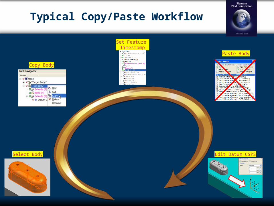
Typical Copy/Paste Workflow
Select Body
Copy Body
Paste Body
Edit Datum CSYS
Set Feature Timestamp

Copy / Paste Features
Use “Instance Geometry” or WAVE to get Topology Only Single Feature Associative back to Original Geometry
Use “Copy/Paste” to Duplicate History Steps Body’s Features may be Selected from Design View Allows Pasted History Features to be modified
Independent of Original May be Used Between Different Parts! During “Paste” All Parent Dependencies Should be
Indicated “Copied” Features should be based on an Offset
CSYS ONLY Only one dependency needs to be satisfied
During “Paste” Expressions may be New, Linked, or Instance
“New” allows complete modification control “Linked” is associative to original, but may be
unlinked / changed “Instance” is identical to original and may not be
unlinked

Instance Features & Geometry
Instance Features (Pattern)
Like I-deas Pattern
Feature Based (Hole, Slot, Boss, etc.)
Rectangular, Circular, Mirror
Individual Patterned Instances may be Suppressed
Instance Geometry
Like I-deas Feature Copy
Geometry Based (Sheet, Solid, Sketch, etc.)
Translate, Rotate, Along Path, From – To, Mirror
Use Within a Single Part

Replace Features
Copy/Paste Adds New Features Parent Dependencies need to be Indicated Csys to Csys Positioning Like I-deas “With Relations”
Replace Substitutes One Set for Another “Group” Features Together for easy Selection Child Dependencies need to be Indicated “Replacement” (New) Feature must exist before any Children
of “Replaced” (Old) Feature in Timestamp Mode Old Feature may be Retained or Deleted All Child Dependencies Transferred to New Replacement
Feature Automatic, Tolerance Based Dependency Mapping.
Workflow Option: Copy Feature(s) from Source Part Paste into Target Part just before Features to be Replaced
Control Position with Csys to Csys Replace Old Features with Newly Pasted Features

Detail Features - Blends
Edge Blend Variable Values (Sets); Variable Radii; Variable
Convexity; Handles Rollover and Self-Intersection; Corner Controls: Set Back; Arbitrary End Cap Surface
Face Blend Conic Shape Control; Tangent Contact Curve
Option; Handles Non-Tangent Input; Variable Radii
Soft Blend Face Blend w/Tangent Contact Curves on Both Sets
Tangent and Curvature Continuity Styled Blend / Styled Corner
Face Blend w/Tangent, Curvature, Radius Function, Interactive Controls
Class “A” Results (No Three-Surface Fillet Option)

Detail Features - continued
“Bridge” Surface Tangent / Curvature
Continuous Connection Surface
Spherical Corner Three Surface Corner
Chamfer Symmetric, Asymmetric, Offset
& Angle Draft / Draft Body
Draft based on Draw Direction, Surfaces, Edges
Match Draft to Parting Surfaces Offset Face / Surface
Offset Faces or Create New Offset Surfaces
Thicken Sheet To Create a Solid
Shell Solid Remove Selected Faces, or
Shell Entire Solid body Emboss
Apply to Sheet or Solid based on Curve(s)

Modify (Edit) Features
Double Click Feature to “Rollback” and Edit To See Feature at Creation Time To Reselect Geometry To Change Values To Toggle Results
“Handles” for Dynamic Editing On Screen Value Dialogs Minimize Mouse Travel Select Feature and RMB “Edit Parameters”
To Edit Feature in “Final” Part Context Select Feature from Part Navigator
Use “Details” Panel to Change Values Works with Sketches, too
“Drag and Drop” to New History Location Cannot Place “Child” before “Parent” Highlighting Shows Parent/Child Dependencies “Dependencies” Tab Gives Expanded Information
Toggle Suppress/Unsuppress RMB Toggle Show/Hide

Measurements & Expressions
All Logical Measurements are Available: Distance; Projected Distance; Radius;
Angle; Tangency… Geometric and Mass Properties
Measurements may be: Associative; Recorded as Expressions;
Checked against Requirements; Reused Minimum Radius; Curvature and Draft Analysis;
Wall Thickness; Dynamic Reflection Patterns “Examine Geometry” like I-deas Part Diagnostics Expressions Dialog Manages All Expressions:
Automatically Created by Features and Measurements
Manually Created by Users Look up Values from Spreadsheet Calculate with Common or Defined
Functions Link to Other Parts Handles All Types of Units and Conversions
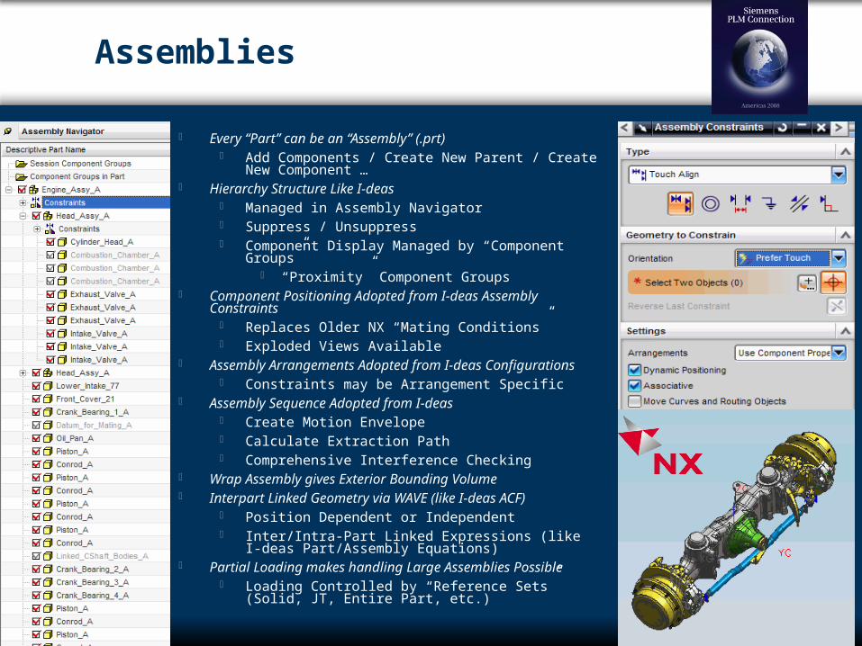
Assemblies
Every “Part” can be an “Assembly” (.prt) Add Components / Create New Parent / Create New
Component … Hierarchy Structure Like I-deas
Managed in Assembly Navigator Suppress / Unsuppress Component Display Managed by “Component Groups”
“Proximity” Component Groups Component Positioning Adopted from I-deas Assembly
Constraints Replaces Older NX “Mating Conditions” Exploded Views Available
Assembly Arrangements Adopted from I-deas Configurations Constraints may be Arrangement Specific
Assembly Sequence Adopted from I-deas Create Motion Envelope Calculate Extraction Path Comprehensive Interference Checking
Wrap Assembly gives Exterior Bounding Volume Interpart Linked Geometry via WAVE (like I-deas ACF)
Position Dependent or Independent Inter/Intra-Part Linked Expressions (like I-deas
Part/Assembly Equations) Partial Loading makes handling Large Assemblies Possible
Loading Controlled by “Reference Sets” (Solid, JT, Entire Part, etc.)

3D PMI & Model Views
3D Product and Manufacturing Information (PMI)3D Product and Manufacturing Information (PMI) Functionality Borrowed from I-deasFunctionality Borrowed from I-deas
Datums, Dimensions, Notes and Symbols, Datums, Dimensions, Notes and Symbols, GD&T, URLGD&T, URL
Model View Based DocumentationModel View Based Documentation Use Existing, Create, Modify, or Delete Model Use Existing, Create, Modify, or Delete Model
ViewsViews PMI Orientation Based on Model View Plane or PMI Orientation Based on Model View Plane or
WCSWCS Section Cuts Through SolidsSection Cuts Through Solids
Crosshatching in Wireframe / Unique Color in Crosshatching in Wireframe / Unique Color in ShadeShade
Search & Report OptionsSearch & Report Options Inherit PMI Types into DrawingInherit PMI Types into Drawing PMI & Model Views Managed in Part NavigatorPMI & Model Views Managed in Part Navigator
Associated Objects ModeAssociated Objects Mode

2D Drafting
Integrated with 3D Design EnvironmentIntegrated with 3D Design Environment
Common UICommon UI
Fully AssociativeFully Associative
Template Based Layouts Speed Drawing CreationTemplate Based Layouts Speed Drawing Creation
Drag and Drop Sheet Size; Views; Border; etc.Drag and Drop Sheet Size; Views; Border; etc.
Dimensions; Datums; GD&T; Sections; Annotations; Dimensions; Datums; GD&T; Sections; Annotations; Balloons; Automatic Parts List; Balloons; Automatic Parts List;
Shaded Views on DrawingShaded Views on Drawing
Assembly / Component Display ControlAssembly / Component Display Control
Hole TablesHole Tables
Inherit PMI from 3D ModelInherit PMI from 3D Model

NX 6: Unique Workflows
WCS Similar to I-deas “Workplane” Persistent, Dynamic, Optional
Layers (Do you think I-deas has layers?) Helps Control Display and Manage Complex Models
Expressions Similar to Part/Assembly Equations May be used Within and/or Between Parts
Sketch and Boolean “Tool” Reuse More Design Intent w/fewer Sketches in fewer
Planes Direct Modeling (Synchronous Modeling)
Parametrically Modify B-Rep Solids No I-deas Equivalent
Assembly Reference Sets Quick loading of Large Assemblies
Visualization “Environments” Enhanced Rendering w/Shadows, Textures,
Reflections Image Based Lighting “Full Screen” and “True Shade” Mode

I-deas Workflows in NX 6
Question: How many of my familiar I-deas modeling, assembly, and
PMI functions and workflows are available in NX?
Answer: Lots. (More than you might think.)
Question: Do I have to abandon my I-deas “Best Practices” and learn a
complete new set for NX?
Answer: NO! Best Practices can migrate as well as geometry.
