i• - defense technical information · pdf file · 2011-05-14dielectric...
TRANSCRIPT

AFOSR G7 - 2551
if THEORY AND DESIGN CONSIDERATIONS0_ •IN DEVELOPING A MULTI-PURPOSE
I• INSTRUMENT FOR DETERMINATION OFTWELVE PROPERTIES
- by W. Leidenfrost
NI
Thermodynamic an d Heat Transfer Section
School of Mechanical Engineering
PURDUE UNIVERSITY
r• Technical Report September 1966
I
-- i
Ii zC L E A P

I
II:
A MULTI-PURPOSE INSTRUMENT FOR PRECISE
DETER:4NATION OF 12 PROPERTIES AT
TEMPERATURES FROM - 190*C TO 650 0 C AND
AT PRESSURES FROM VACUUM TO 500 ATM
A. General Theory and Design Considerationsin Extending Capability of a ThermalConductivity Cell to That of aMulti-Purpose Instrument**
by
W. LzAdenfrost
* The paper was presented at Physikalisch TechnischeS- Bundesanstalt Braunschweig, Germany in January 1966.
at VDI meetinq Hochdruck-Verfahrenstechnik in Baden-Baden, March 1966 and also at the 6th ThermalConductivity Conference at Dayton. Ohio
** Successive papers will describe in detail the designof the major part3 of the multi-purpose instrumentand experimental results obta n.d.
*** Professor of Engineering. Purdue University, Lafayette,Indiana. U.S.A.

-I
I TABLE OF CONTENTS
I Page
LIST OF FTGURES & TABLES i
ABSTRACT ii
[ NOMENCLATURE iii
INTRODUCTION 1
I MEASUREMENTS TECHNIQUE 3
Thermal Ccnductivity 3
Dielectric Constant and Index of 5Refraction
I Electrical. Conductivity (a.c.) 7
Electrical Conductivity (d.c.) 7
Thermal Expansion Coefficient of 8Instrument Material
Thermodynamic p-v-T Properties of 10If Gases and Vapors
Vapor Pressure of Liquids 12
Compressibility and Thermal Expansion 12I Coefficient of Liquids
Specific Heats cp and cv of Liquids 13
BASIC DESIGN CONSIDERATIONS 17
Temperature and Pressure Measuring Ranges 17
Thermostating the Instrument 18
Providing Isothermal Conditions at 21Surfaces Wetted by Test Fluid
New Method for Elimination of Errors 23in Determination of Surface Temperature
i TIME NEEDED TO ESTABLISH STEADY STATE 34
TF4PERATURE CONDITIONS
STHE CENTERING ROD 36
THE FINAL DESIGN OF THE INSTWJMENT 40
SACKNOWLEDGMENTS 44
r REFERENCES 45
r

E
LIST OF FIGURES
Fig. Page
1 Thermal Conductivity Cell 3
2 Measurement of Geometric CoDstant B 6
3 Error Due to Eccentricity 9
4 Schematic Layout for Experimental 12Setup to Measure Coefficients of ThermalExpansion and Compressibility
5 Temperature Change Within Calorimeter 14
6 Wiring Diagram and switching arrangement 16for measurement of the different propertties
7 Thermostat 20
8 Influence of Wall Thickness on 22Temperature Distribution
9 Disturbance of Temperature Field 2510 Pt-Resistance ThermomFoter 27
11 Cross-Section of Composite Structure 28
12 Transient Heating of Cylinders
13 Centering Rod 39
14 Cross-Section of Multi-Purpose Instrument 4115 Multi-Purpose Instrument Assembled 43
LIST OF TABLES
Table Page
i Dielectric Constant of Several Test 7Fluids of Highest Purity MeasuredUnder Normal Conditions
2 Steady State Temperature Distribution 30in Walls of Instrument Adjacent toSurfaces Wetted by a Fluid(kflid = 0.1 kt; AT = 10C)
3 Steady State Temperature Distribution 32in Walls of Instrument Pdjacent toSurfaces We'tted by a Fluid(kfluid 0. k water AT 2*C)
4 Steady State Temperature Distribution 33in Walls of Instrument Adjacent toSurfaces Wetted by a Fluid(kfluid = kwater; AT =1C)
-I i

LIST OF FIGURES
Fig. page
1 The.rmal Conductivity Cell 3
2 Measurement of Geometric Constant B 6
3 Error Due to Eccentricity 9
4 Schematic Layout for Experimental 12Setup to Measure Ccefficients of ThermalExpansion and Compressibility
5 Temperature Change Within Calorimeter 14
6 Wiring Diagram and switching arrangement. 16for measurement of the different properties
7 Thermostat 20
8 Influence of Wall Thickness on 22Temperature Distribution
9 Disturbance of Temperature Field 25
I0 Pt-Resistance Thermometer 27
11 Cross-Section of Composite Structure 28
12 Transient Heating of Cylinders 35
13 Centering Rod 39
14 Cross-Section of Multi-Purpose Instrument 41
15 Multi-Purpose Instrument Assembled 43
LIST OF TABLES
Table Page
1 Dielectric Constant of Several Test 7Fluids of Highest Purity MeasuredUnder Normal Conditions
2 Steady State Temperature Distribution 30in Walls of Instrument Adjacent toSurfaces Wetted by a Fluid(kflud = 0.1 kwater; AT = I1C)
3 Steady State Temperature Distribution 32in Walls of Instrument Adjacent toSurfaces We-ted by a Fluid(kflid 0.1 kwater; AT = 2*C)
4 Steady State Temperature Distribution 33in Walls of Instrument Adjacent toSurfaces Wetted by a Fluid
(kfluid =kwater AT=C)
ii

ABSTR ACTF
The d'evelopment of a new 1nsc•-r~ent is -;e.-,u e
and also te-chniques of measurement to- dJet- rmne; for fuids
1)I thermal Conductivity, 2"! dlclect~ric c:sa~,am:cc
3) index of refractilon, 4) eletrca co z!
U5) electrical conductivi'tv dc for- qase-s and va pors:
6) p-v-T propert-ies; for linu~ds: 7)thx-l-=c;sn
*Coe ff icin, compressi ba, z v, 91 va-por
10) specitic heat C, 1;sce-ific hetC Z-ot,* &&
""12 specific heat; and forx kn s t ru r-t Mater 1 s;teraexpansion coerfficient- and Youna's Mocdulus. Ai';e-w
thermostat- operating from about -i9Oc:C to-6500- -s
described. T.hi s de vic _e i s c on1vt-rŽIled a u torn atiicaiva
can follow preset temperat-ure-timne ruca~. DetaIc
analysts xs mad'e for the procetrue necessary to estalsi so--t h e-rm al cundit;.ons att surfac-es wetted o the tsIsubstances and to evalua.,te Gdevriat'I-ons fror- s unond~t: ons
CU- to tedtubance othe temlperatr field in theI ~~t no i -borhoA of the surfa'ý-ces c-aus:2d b~yteteertr
senisinq, elements. Th1Ais alIso is important so I-bat th
ccrrc,.ct surfa-ce tempoer--;t-ure ca_,n be derixved f romthfrr;.
ings of the thermiometl-er. T'he constructcon o czrn
rod (-he most critical part of the multipurpose instrument
be ring a do'u'blie elIe~ct ricalyI v shielided lead-inr an&Se a center-J~na device is desc-rie as 's also briefly the eza dSaIyg
I of the appar-atus.
I%

I ~ZUSAMY.FMASS1NG
Die Entwicklung eines neuen Instrumentes lund die
Technik der Messungen werden beschrieben flur die Bestlimmung
von Stoffgrldssen von flUssigen Medient 1) Wgrmeleitzahl,
12) D~ielektrizit~ats-KonstL-ante und damit, 3) Behal4) elektriscbe Leitf~higkeit (Wechselstrom), 5) elecktrischeI Leitfiihigket (Gleiclistrom); von Gasen -and Dampf en: 6) p-v-TZu~tandsgro"Ssen; von Fl~issigkeiten 7) thermiseher Ausdeh-nunigsko-
p effizient, 8), Kompressibilit~it, 9) Dampfdruck, 10) speeifischeWirne c., 11) speeifische WArme c i;ind von fest',ýn K6rpern:12) speelifische Wa~rme -and W~armeavsdehnungskoe~f"isient,- widI Eslastieita~tmodul des Instrumentmnaterials. Ein neuer Thermostatder in elnem Ternxperaturbereich von -1900C bis 465E,000 arbeitet
wird besChrieben. Dieses Instrunent wird automatischgeregelt und kann vorbesctimmten Temperaturr-Zeit-T~unktionenfolgen. Die notwendigen Sch~ritte -an isotherme Verh~ltnisce
an den, von der Versuchssubstanz benetzten Wandungen, zuerreichen, werden analysis"rt. Ebenfalls die Abweichungen
vom isothermen Verhalten infolge der St'6ringen des TemperLatur-feldes durch die eirngebauten TLemperatciriiihler. Was auch
Uwichtig 1st fur,'. die Ermitt'lung des Temperatur::-falles ia derWand um die wahre CObe rf lchen-rl-emDere.tur zu erhalten. DerKritischste Tell der Apparatul- istL die Zentrierunig die
gleichzeitig als doppelt elektrisch abgezzhirmate Zuleiturng
I dient. Die Konstruktion dieses Zentrierhalses 1st imeinzelnen besch-rieben -and ku~rz nur der e~lgaltinge Erntwurf
des gesamten MehrzweCkmessge-rittes.
ipi

NOMENCLATURE
A average cross-sectional area of test fluidin gap between hot and cold body
IAr surface area of calorimeter heater
Sa thermal diffusivity of sample
B geometric constant
I b wail thickness of instrument
C electrical capacitance of the cell assembly
I c specific heat
C cv specific heat at constant volume
cp specific heat at constant pressure
I D dielectric loss of test fluid
I electric current through heater of hot body
I Al error in current measurements
i electric current through test material
k thermal conductivity of test material
k h apparent thermal conductivity of thermometerplaced in a hole
kw thermal conductiuity of material of instrument
kAu thermal conductivity of gold
L thickness of layer of test fluid also usedfor half-wavelength of locally periodic temp-erature distribution
1 thickness of wall between s-rfa-e and 1-.cationof thermometer, thermometer perfectlycentered and uniform heat contact
1Iy thickness of wall between surface and locationof thermorter, thermometer not perfectlycentered and no uniform heat contact.
I liii
S-1

m mass of test sample
f n index of refraction
AP electrical potential difference betweenhot and cold body
p pressure
q continous power input into heater of calorimeter
qc hheat flow by tree congection
q inh increase of heat flow due to inhGmogeneitiesin temperature field
I k heat flow by conduction through layer of testfluid and walls of instrument
I heat loss from hot body along centering rod
q osc heat losses or gains due to unsteady stateconditions
q r heat flow by radiation
I R outer radius of calorimeter, also used forelectrical resistance of test fluid
I r outer radius of calorimeter heater
T temperature
I t time
i Tcold surface temperature of cold body
Thot surface tempezature of hot body
T 0 initial temperature of instrument
Tm amplitude of temperature fluctuation
m Ttemperature change in time
V electrical potential
AV error in potential measurements
i -,

v specific volume of test material
W width of nonisothermal area
W heat capacity of calorimeter bodyC
x coordinatei
y coordinateiGreek symbols
thermal expansion coefficient of test substance
E dielectric constant of substance
C dielectric constant of gasg
E capacitance of vacuum
/C compressibility coefficient
X electrical conductivity
xa.c. electrical conductivity (a.c.)
Xd.. electrical conductivity (d. c.)
T dimensionless time
Sdim ens io n le ss tim e w h en steady sta t econditions are achieved
e dimensionless temperature
W frequency
dimensionless coordinate
dimensionless coordinate
v
I
I:
INTRODUCTION
4 A knowledge of the properties of materials over wide
ranges of pressure and temperature is essential to present-
day technology. To determine all properties of all materials
is a never ending and practically hopeless task because new
materials are constantly developed, and furthermore, data are
sometimes needed under conditions where it is impossible to
carry out measurements.
In addition to the needs of the engineer, a scientist
who tries to predict property values by statistical mechanics
requires basic inf-rmation in the form of accurate property
values to verify and check his models. The more information,
i . the more data of different properties of importance
to theory, he obtains and the wider the range of pressure and
temperature in which those values have been observed, the
more successful his theoretical treatment becomes and the
reliability of calculated data increases even for conditions
where measurements are as yet impossible Al! the facts
make it understandable that in the last decades a large and
constantly ircreasing effort has been spent in expanding our
knowledge of properties of materials. The results obtained
so far are behind expectation for many reasons. One of them
is that different properties of the same material or
properties of different materials measured normally are not
observed under identical conditions of pressure and temperature
This is also true when the same property has been investigated
in different apparatus. The situation is worsened by the
fact that tests in different apparatus of a supposedly same
material have not necessarily been carried out with material
that is, in fact, identical Impurities might not have been
the same to begin with and furthermore the material might have
changed differently during the various tests. Intercomparisons
are therefore very difficult to make.

These difficulties accompanying property research
can be lessened or avoided by using multi-purpose instruments
able to determine simultaneously several properties in one
and the same instriunent under identical conditions of pressure,
temperature and impurity content, and over ranges of pressure
and temperature which are as wide as possible but feasible
for precise measurements. Simultaneous determinations of
more than one property can improve in addition the precision
I j of the investigation because one observed property might be
needed for the correction of another one measured in the
instrument under identical conditions.
The use of multi-purpose instruments p-omises also
to be of advantage in the field of biology Property determ..i-
ations of organic m•aterial might be a tool to study macro-
molecules and to detect most of all the changes of their
qualities under the influence of varying environment conditions.
Multi-purpose instruments applied for property
research will also.> reduce costs, time and manpower since only
one instrument, one instrumental setup and one group of people
are needed for the measurements of several properties. For
the observations of each of these several properties one
normally would need a specific instrument with all its
facilities and also people to use it. Therefore it can be
assumed approximately that the n properties measured in a
multi-purpose instrument are obtained for i/nth of 'he cost
it othe:-wise would be.
The merits of using a multi-purpose instrumentdiscussed so far have already been pointed out briefly in a
previous paper (1] by the author where research with a thermal
conductivity cell was described. The possibility of extending
m a * This work was supported by the National ScienceFoundation and the United States Army Research Office.Their help initiated and made possible the first
m |steps towards the development of the multi-purposeinstrument and is acknowledged with deep appreciation.
2I•m m m wn~m|mmn|ml m~mm n lm ~ m m m mm• mln iaum u
u c capablityof t���t •iW 4.tiu,,,rL tO thhaL of a multi-purpose
instrument was offered more or less self-evidently by
using the cell. (This fact was also demonstrated in
short in [(].)
As a result of these observacions, an extensive
analysis was initiated in 1964 to find the most feasible
design. This was followed up with first sketches. A contract
7 from the Air Force Office of Scientific Research then made it
possible for the author to develop and to design the multi-
fT purpose instrument at the Physikalisch Technische Bundesanstalt
in Braunschweig during a leave of absence. Due to the fact
that the previous investigations had gathered already important
information the instruient not only was designed but alsor[ was built during a one year period of time.
7 MEASUREMNTS TECHNIQUE
Thermal Conductivity
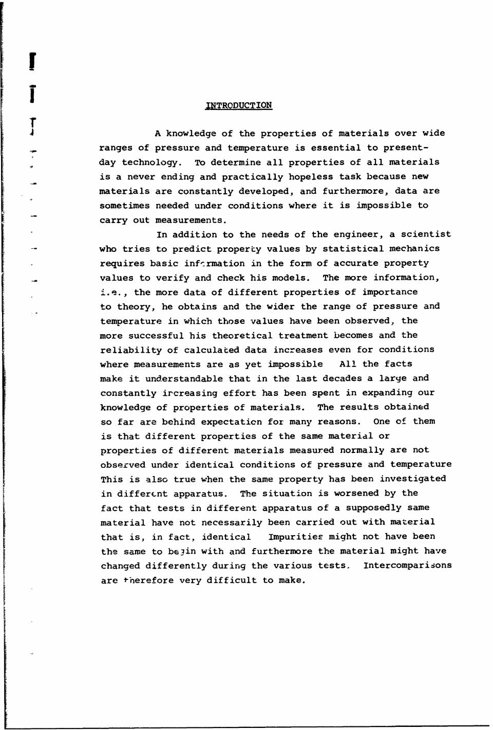
Cal VnThe instrument formeasuring thermal conductivity has
been described in detail in [3]-cow ody and therefore Fig. 1 only shows
the cell schematically but in
sufficient enough detail that the
procedure necessary to extend its
capabilities for the observationof other properties can be discussed.
The instrument consists ofI :a cylindrical heater element (hot
body) with hemispherical ends,-- ,-- -~ 'placed and centered by means of a
,- centering rod, within a similarly
shaped but slightly larger cavity
FI I TEP .AL COWIUCT, Y CELL
3

of a cold body. The test fluid fills the gap between the
two bodies. The arrangement operates without guard-heaters
and allows therefore steady state to be reached in a short
time, also of importance to avoid and/or minimize influences
I ~of temperature fluctnations.
In this case the thermal conductivity k can be
readily obtained from Fourier's law
A (T)qk L hot cold1
where
qk =(V+AV)(I+_) - q r - qc t qL t (qosc.)hot - (qosc.'cold
(qinh)hot - (qinh)cold- (qinh)fluid t (la)
is the heat flow byj conduction, equal to the electrical
fpower input corrected in order for radiation, convection,
lead in losses, heat flow due to unsteady state condition
and/or inhomogeneities. Thot and Tcold are the surfacetemperatures of hot and cold bodies.
For absolute measurements it is necessary to determine
the geometric constant of the arrangement, i.e., the ratio of
overall heat transfer area and the average thickners of the
fluid layer. The value is influenced by surface roughness
and other inhomogeneties. The determination of the geometric
constant can be done most accurately by measuring the
electrical capacitance because all disturbances will be
included. The capacitance measured will be
C= .v B (2)
where B A geometric constant
E•v = capacitance of vacuum
I = 8.8541735 x 10⁻¹⁰ Farad/cm
Eg= dielectric constant of the gas
= 1 for vacuum
1_4
~I
In a vacuum one observes the geometric constant
T B _ C (2a)EV
directly and accurately when the centering rod enclosing the
electric wires is built in such a way that lead-in capacities
have no effect. This was achieved by a three-lead measurement
technique [2].
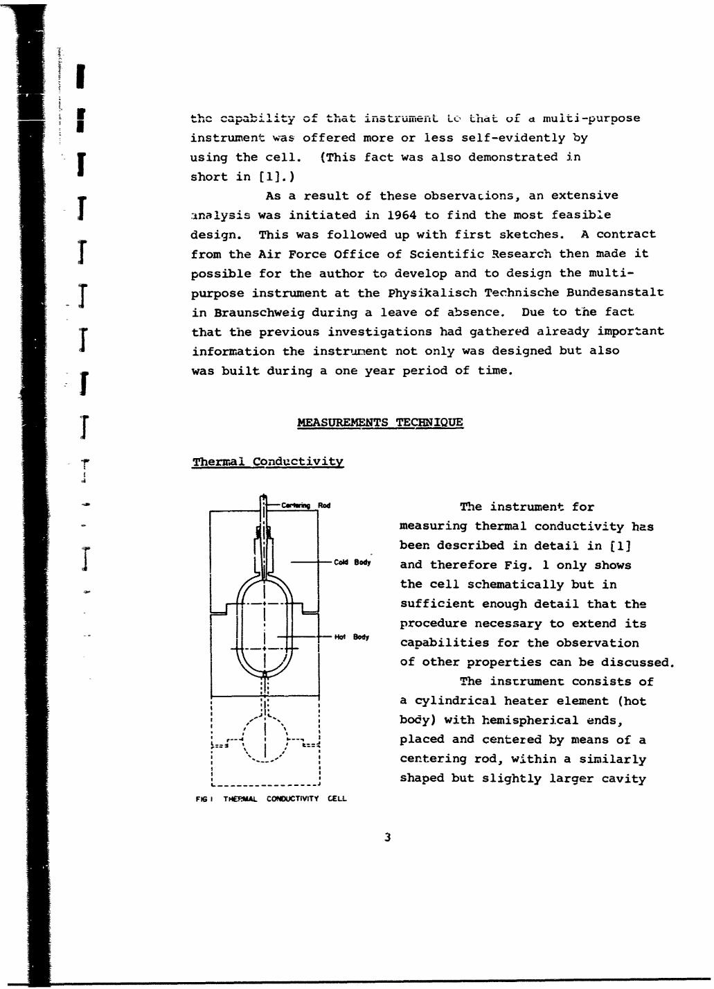
If the axis of the hot body coincides with that of
the cold body the capacitance is then only a function of
vertical displacement as shown in the upper part of Fig. 2.
The almost parabolic capacitance curve has a minimum at a
location of least disturbance, i.e., the most homogeneous
field, which is therefore the best location of the hot body
within the cavity of the cold body. For this setting, the
value of the capacitance measured (and therefore the geometric
constant) can be readily taken from the hundredfold magnified
part of the curve in the neighborhood of the minimum as shown
in the lower part of Fig. 2.
Dielectric Constant and Index of Refraction
Measurements of the capacitance when the instrument
is filled with test fluid allows the determination of the
dielectric constant of the test material with the aid of
equation 2. The feasibility of this arrangement had been
demonstrated in [1]. The data there observed are shown in
Table 1.
The dielectric constant of many substances is
proportional to the square of the index of refraction and
therefore this third property can be determined simultaneously.
The knowledge of the refractive index is of importance for
the evaluation of radiant heat transfer which in turn is needed
for computing the correct amount of heat transported by conduction
t only when thermal conductivity data are measured--see equation la.
5

7.CCENI HIC-I Yr Miiiimeiers-05 -04 -23 -0 Z -02 0 011 02 03 04 0.5 O6 071 "
TURNING ANGLE OF THE CENTERING TUBE .Degrees100. 200300 400 500 600 700 0 0
w~u-a 2556Toowd~at *m GW
16860 - 250-- :
16855 -- 245- _ -
;8 50 - -- 24C;.-
i6845
16840 -- 230,-,
168 35 - -225 .. . ....
168 30v 220_--- -
.• ,6825 - - 25 .
01 -
~66 20- - 21- -
A-8 15 - -1-205--z 0
rl I-81 --- _1 - -- 200-- --
< a A+ --- 9 5O -- - - ,,- -
16835 .. 195
I .800 - 190--- .
16795 -4-- - . ......-...
/790 - 1 716780 , 0----
Yv.0 - Measujred by moving
o/ healer elemeal downwo-fS16775 t•65o 0. A - Me'•sure by o vin'01% heater elefMen upwods
!6770 B 8 18937,ucmn
F 167680 p F
167651-26 270 Z8O 290 300 310 320 330 340 350 360 370 380 390
TURNIiNG ANGLE OF THE CENTERING, TUBE Degrees
-008 -006 -004 -002 0,0o 002 004 006 08 010
ECCENTRICITY miinters
j FIG. 2 MEASUREMENT OF THE GEOMETRIC CONSTANT, B
6

TABLE 1. DIELECTRIC CONSTANT OF SEVERAL TESTFLUIDS OF HIGHEST PURITY MEASUREDUNDER NORMAL CONDITIONS
Material Argon CO 2 Toulene
Temp.,C 25.04 24.00
Press. ,mm Hg 746.76 755.14
e(measured) 1.0004932 1.000899 2.3787
N.B.S. value2. 379corrected for the 1.0004996 1. 0009038 (not
same temp. & press. corrected)
Departure -6 pp m -5 pp m ----
Electrical Conductivity (a.c.)
The capacitance bridge used for the measurements just
discussed will yield a precision of six figures only if the
loss is balanced equally precisely. The bridge then provides
the dissipation factor D and/or the conductance of the
sample for a particular frequency w.
D = wRC (3)
Therefore the electrical conductivity of the sample can bedetermined for the respective range of frequency.
Electrical Conductivity (d.c-.
The electrical wiring necessary to measure capacitanceand/or a.c. conductance provides in addition to observe the
d.c. conductivity of the test fluid by applying Ohm's law.
i = XBAP (4)
where i is the current flowing through the test layer of
geometry B under a potential difference AP of hot and cold
body.
7

I
i Thermal Expansion Coefficient of Instrument Material
J Measuring in vacuum the capacitance of the
arrangement as a function of temperature produces the
geometric constant as a function of temperature due to
the change of the geometrical arrangement as a result of
the thermal expansion of hot and cold body. Equation 1
I shows that the change in capacitance and/or geometric constant
is directly proportional to the linear thermal expansion
J coefficient. But the value of this property will be correct
only when the temperature change does not introduce at the
same time a change in the position of the hot body in respect
to the cold body surrounding it. Otherwise this would
disturb the field resulting in an apparent increase of C
and/or B. To hold the hot body in the same place in respect
to the cold body under varying temperatures is possible only
when the centering rod changes its length with temperature by
an identical amount as the material of the cold body does.
This can be achieved perfectly only when those two parts of
the instrument are made out of the same material. The
centering rod as already was pointed out must be built as a
double electrical shield and it has to fulfill many additional
and partially controversial requirements (this will be discussed
later) and cannot be made out of the materials used for the
cold body. As a result of this. there will be a displacement
of the hot body within the cavity of the cold body. The
error as a function of this eccentricity is shown in Fig. 3
(duplicating part of Fig. 4 of r[i) where the capacitance,
made dimensionless with the minimum value, is plotted
versus eccentricity. The curve of that figure represents
the error due to eccentricity for the geometrical arnangement
shown in Fig. 1 and when eccentricity exists only in the
.'?herical part It can be seen that axial displacement of
0.05 mm (i.e., 10% of thickness of layer of test fluid)
results in an increaoe of capacitance and geometric constant
8
!

!I
1.005
1.004
L003 - -Theoritically predictedv, o Measured by moving
heater elementdownward
S, a13,A - Meoswed by movingheater element
upward1002
1.004 0of%_1 0/
1.0001 1 A
_______ h _ __ __ _ _/
-0.08 -0,06 -004 -002 ODO 0.02 0.04 006 0.06ECCENTRICITY, Millimeters
FIG. 3 ERROR DUE TO ECCENTRICITY
of only 0.15%. A displacement of less than 0.015 mm
introduces errors of the order of one hundredth of a percent
and becomes negligibly small. The discussion of the design
of the centering rod will demonstrate that its composite
structure can be designed such that it has a thermal expansion
coefficient equal to that of the material of the cold body--
but only for a certain temperature range. The thermal
expansion coefficient for other ranges of temperature can
be expected to be similar to the cold body material but not
identical. Its true value can be determined with a high
degree of accuracy by measuring the capacitance of the
geometrical arrangement of the multi-purpose instrument
first when the hot body is holding the centering rod and
9

secondly when the hot body rests on a piece of ceramic (the
centering rod acts then only as a centering device but allows
axial motions) so thick that minimum capacitance is achieved
in accordance to Fig. 3 This thickness nominally is 0.5 mm,r and pure alumina would change its length in a 1000°C temperature
range by a few thousandths of a millimeter. This expansion
jwould displace the hot body in respect to the cold body cavity
but according to Fig. 3 the influence of this displacement
would have practically no effect on the capacitance values
measured In this case the true thermal expansion coefficient
of the instrument material would be obtained.
Comparison of those correct capacitance measurementswith those obtained when the centering rod fixes the position of
the hot body yields the thermal expansion coefficient of the rod.
This value is of interest only for determining the influence
of changing inhomogeneities on the measurements of all properties
where the geometric constant B is a major quantity.
Knowing the thermal expansion coefficient of the
instrument material with the pretision with which the capaci-
tance measurements can be made makes it possible to determine
the true volume occupied by the test fluid within the multi-
purpose instrument at any temperature whenever the volume has
been measured accurately at one temperature. This fact offers
another possibility for using the multi-purpose instrument.
Thermodynamic p-v-T Propertics of Gases and Vapors
Determinations of p-v-T relations in any kind of
instrument is normally influenced most severely by the
thermal expansion, introducing deviations from isochoric
conditjions. The multi-purpose instrument, as proven in the
previous section, allows thermal expanszon coefficient of the
material of the instrument to be measured with a high precision,
and therefore p-v-T data can be obtained accurately. The
influence of pressure on the volume is much smaller than thetemperature effect and can be made small by making the walls
10
I

I
of the instrument strong enough (thick enough and/or out of
a material of high strength over the operating ranges of
temperature). The change of volume with pressur3 can be
determined accurately by c pacitance measurements and when
the instrument is charged with a gas of well known pressure
dependence of its dielectric constant. If, in addition, its
temperature dependence is known, the capacitance measurements
will yield the change of volume with pressure and temperature.
Accounting for the thermal expansion coefficient (measured as
a function of temperature in the previous section) makes it
possible to determin'i the volume change at different temperatures
as a function of pressure only. With this information, Young'smodulus of the wall material and its temperature dependence canbe derived.
The pressure influence on the volume can be madenegligibly small when the apparatus iz held under the samepressure outside that exists inside. In this case only thecompressibility of metals must be considered. Enclosing the
apparatus in a high pressure vessel makes the instrumental
setup somewhat more complex. The high pressure vessel mustremain for reasons of size, cost a.o. near ambient, the
instrument only undergoes temperature changes. The thermalinsulation of the instrument will be pressurized and due to
increasing free convection heat transfer becomes more andmore ineffective with decreasing temperature and increasing
pressure. As a result of this, the temperature range of the
measurements with the instrument might be limited to such a
temperature where the thermal load cannot be handled anymoreby the thermostat.
The volumE occupied by the test fluid within themulti-purpose instrument needed to be small for all the
property measurements discussed under the sections on pages 3through 7. For p-v-T data determination a larger volume is
ii

a
more feasible and the best way to increase the space is to
add another cavity to the instrument--most suitable in theshape of a sphere as indicated in Fig. 1 by dotted lines.
I P-v-T measurements yield the compressibility
factor. With known specific heat data then enthalpy, entropy,
j free energy and other thermodynamic functions can be derived
from the measurements.!Vapor Pressure of Liqjuids
IP-v-T data on gases and vapors can be conviently
observed only when condensation in a portion of the volume
I does not occur. Also, fluctuations in volume in the manometric
section must be eliminated. A vapor pressure measuring
device working at measuring temperatures and under isochoric
conditions has been discussed in [i]. A similar but more
sophisticated device will be used in the multi-purpose
instrument--which then obviously can also be u3ed to determine
vapor pressure of liquids. As for vapor pressure data only,
it is not necessary to !now the composition of the liquid
and vapor fractions.
Compressibility and Thermal Expansion Coefficientof Liquids
Connecting the multi-J purpose instrument with
SAV Volume external instt umentationof by means of thin capillaries,
. AV Sample
If(T,P) as shown schematically
j 1in Fig. 4, makes it
possible to observe the
change of liquid level
Sresulting from changingtemperature and pressure
FIG 4 SCHEMATIC LAYOUT FOR EXPERIMENTAL of the test fluid withinSETUP TO MEASURE COEFFICIENTS OFTHERMAL EXPANSION AND COMPRESSOLITY
1 12
I

Ithe instrument. Accounting for the change of ; -e due to
thermal expansion and/or under pressure of the i-sterial of
the instrument yields then the thermal expansion coefficientI? and/or the ccefficient of compressibility of the test fluid.
Errors in those determinations can be made small by
AP avoiding change of volume with pressure and/or temperature of
the external instrumentation and by eliminating effects of
sufface tension on the liquid level observed.
Specific Heats c and c of Liquidspi v
E.0- Schmidt and the author described an adiabaticcalorimeter [3] working in a quasi-steady state under continuous
heating. The specific heat for this case is given by the
equation
1 W (5)m T cT
where IdT is the temperature change with time of the test-dtmaterial observed under constant heat input q into a sample
of heat capacity mc being enclosed in a calorimeter body of
heat capacity Wc
The specific heat measured in an instrument like thiswill be of high accuracy whenever the constant and continous
heat input produces at any location witbin the sample the sametemperature increase with time and whenever the temperature
difference within the sample is so small that the specific
heat can be assumed to be constant but large enough to detect
the temperature change accurately.
These conditions can be provided, as was proved by
the authors, by solving the partial differential equation
describing the temperature field in the sample of spherical
geometry under the assumptions that heat input to the sample
takes place only at the suiface of the heater element locatedat the center of the sphere, that there are no heat losses from
13

the outer surface and, finally, that at a time zero uniform
L....erature . i..Ti4 uon ex rists within the sample.
The solution is given in Fig. 5 where the dimensionless
temperature e is plotted versus dimensionless time T for
different dimensionless locations •.T-To * a •t xr
0 ==Fo a t rR R
k Ar
j with R the outer radius of the calorimeter,
r the outer radius of the heater of surface are:i Ar
jk and a thermal conductivity and diffusivity '-. the sample.
IP(w
=P
IW
TIME: Tb
FIG. 5 TEMPERATURE CHANGE WITHIN THlE CALORIMETER
At • = •, i.e., at the surface of the heater elemnent, the
temperature of the sample increases first rapidly but then
with decreasing slope until a constant rate is maintained.
Due to finite thermal diffusivity, the heat input started
at time zero causes, at the outer surface at location • = •(*
•Fo = Fourier number A814
I
• l • I u mm • mm m • m iinm l ~ n • • mm n • m l r lwm m • m ~ b|M •
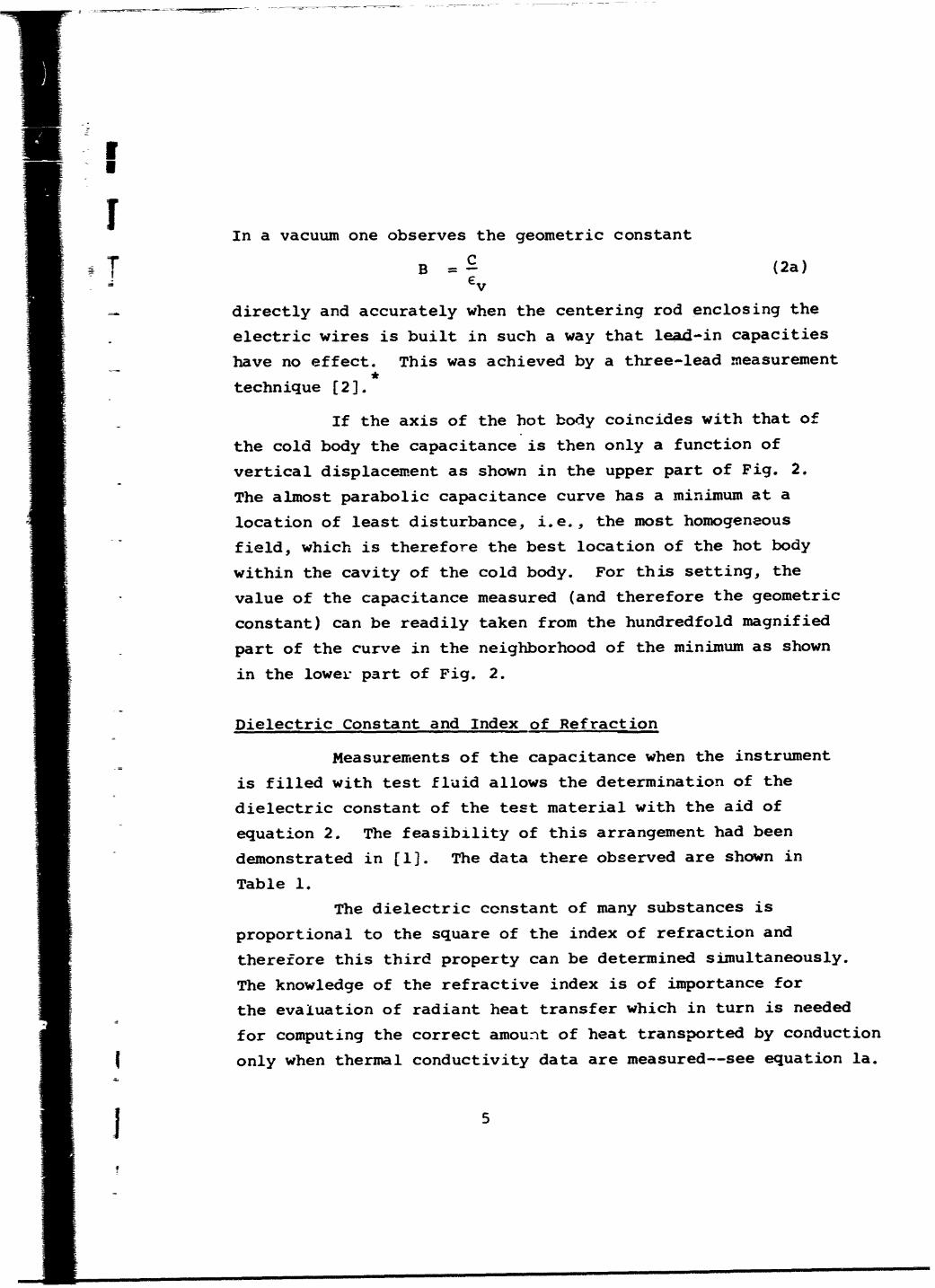
= I first a slower change of temperature with time which then
also continues at a constant rate. The constant rate of
temperature change indicates quasi-steady state conditions.
The bulk temperature of the sample increases from time zero
on steadily--and the temperature difference within the
sample remains constant for all times greater than Tb. All
measurements taken after time Tb will yield the true specific
heat at the respective temperature,
The analysis for other geometries of the sample,where the temperature field is dependent on more than one
coordinate and influenced in addition by free convection
heat transport within the sample is practically impossible to
accomplish, but, on the other hand, solutions are not needed for
those cases because the geometry of the sample is of less
concern and free convection will increase the apparent
diffusivity of the sample making measuring conditions more
feasible than for the case of granular materials or very
viscous fluids of low diffusivity as was considered by E.O. Schmidt
and myself.
For these reasons the multi-purpo3e instrument also
can be used to determine specific heats. The hot body will
then be replaced by a calorimetric container of similar outside
shape enclosing the sample of known mass. The cold body acts
as an adiabatic envelope; its temperature musi. change in time
by the same rate as the outside of the calorimeter does and
the temperature difference between the two bodies must remain
at zero. This requirement can be achieved by using the
thermostat discussed in its own section on page 18.
For measurements of specific heat c the calorimeterpcontainer will accomodate a bellow or other flexible device
separating the liquid tested from a gas at constant pressure
and allowing the test material to freely change its volume
with temperature.
15

For measurements of c the same calorimeterv
arrangement can be used, but the flexible device can either
be removed or inactivated and isochoric conditions aremaintained.
The steps discussed under Measurements Techniqueare necessary and more or less easy to achieve so that thecapability of the thermal conductivity cell can be extended
to that of a multi-purpose instrument. This instrument willbe able to observe simultaneously six properties (k, E, n,
a.c. 'X d.c." p-v-T) of the eleven listed when gases andvapor- are tested and seven properties (k, E, n, Xa.c.J
Sd.c. , Kc) when liquids are tested. Simultaneous in this
respect means that on thetest fluid originally filled
12 e.ct-C ceejwcttY) of %A*into the instrument all
measurements are carried-• L- -- _ _ out and made possible by
- altering only outside
- i •connections as is
schematically shown in
Fig. 6, but the sampleof 'klf 7=. - "P~v.? of gnm wd vaW s
vow flU qu . always remains the same.3 VW."r tw. r OR CW10c-O"MIef6"
o Iw"Ltem fflW "Rao"" Therefore the different
P? , properties will be
I 'observed under perfectly
y identical conditions.
- -I Those ideal situa-
tions cannot be providedWiring diagram W g gfor the other measurements.
wid swrtctwI w=O gw,*wrt f~w f1UOs4unrf*tS oo * s4wrdt opoplrs•s: For specific heat determin-
g .6 i ation the instrument itself
m•st be altered and this
*The same arrangement can be used to measure thespecific heat of solid materials as E.O. Schmidt and theauthor d-d.
11
III ~ rII i • i l l l ~ I I I II m iii i i i ii

necessitates moving the sample from the cell. Relocating the
sample could be done by filling the calorimeter with the test
substance being taken out of the instrument. Careful
procedure should make it possible that the sample does not
change during this process and when, in addition, the walls
of the calorimeter and multi-purpose instrument being wetted
by the test fluid have no effect, then a quasi-simultaneous
determination of those properties are also possible and all
data measured with the multi-purpose instrument will be
obtained under practically identical conditions: pressure,
temperature and impurity wise.
The techniques of measurement of the various
properties with the multi-purpose instrument discussed so far
represent first information towards a preliminary design but
much more must be considered to reach the final design and
to build the instrument.
BASIC DESIGN CONSIDERATIONS
Temperature and Pressure Measuring Ranges
One of the main requirements to be achieved by the
multi-purpose instrument is to produce property data of high
precision. The ranges of temperature and/or pressure must be
chosen so that accurate measurements are not only possible
but also made over a large range of these variables. For
temperature, the working range of the instrument will be from
-190 0 C to 650 0 C because in this range the platinum resistance
thermometer is presently being recognized as standard for the
international temperature scale. Selecting the temperature
range limits to a certain extent the pressure range due to
the strength of material of the instrument. Chosen was the
range from vacuum to 500 atm which is felt sufficiently wide
because the pressure dependence of many properties is small.
17

I
The ranges selected will be of influence on the
design of the apparatus itself Lut more so in respect Lo the
measurements with the instrument since all quantuijes needed
to be observed for computing the various properties ftoin the
respective governing equations must be determinable accurately
at any pressure and/or temperature. Pressure and temperature,
in addition, must be precisely maintained at measuring
conditions fu;r at ir•-st that length of time needed to achieve
f steady statc conditions arid to take the readings.
GeneratJng. changihg., holding and meas•r i.,g piessure
Scan be done in most cases without difficulties but not for
"ltapor and gas pressure under isocnoric conditions- 1_11s will
j -e discussed in more detail by dealing with the design of the
instrument. Pressure, in addition, will be un. form within the
j instrument at any time and under any circumstances.
",-he sitjation is much more difficult in rc-spct to
temperature and considerable effort must be spent in tin erz.
design and fabrication t3 overcome those difficulties or to
minimize errors.
Thermostating tne Instrumernt.
I Tempexature r,:gulation by mpans of electtical
heating wiies is insufficient because it is practically impos-
j sible to produce the same amount of heat per each length element
of the heating wire and most of all uniform contact between
wire arid the walls of the instrument cannot be achleved,
Furthermore, electrical heaters are useful only at temperatures
above ambient; cooling by means of the Peltier effect is not
effective enough in most cases.
I Boiling point arrangements do promise excellent
temperature control but changing from one value to :±• otne,
needs pressure regulation- over wide ranges andor the use of
different media.
I 18
i !

lI
Commercially available liquid thermostats operate
r very satisfactorily--but normally only in narrow ranges of
temperature and, in addition, the use of different fluids is
also required for different temperature ranges but those are
not as wide as needed for the multi-purpose instrument.
It was therefore necessary to develop a new thermo-
stat able to operate with one working media sensitively in
the range required, A gas appears to be the best to use and
helium was selected because its high thermal conductivity
and low viscosity offer good heat transport capabilities.
The thermostat is shown schematically in Fig. 7.
The helium is circulated by means of a pump in a closed loop.
This loop consists of a bafilar coil and a heating section.
A platinum resistance thermometer is used as a sensing element
in an automatic control system- This system changes heat input
and/or cool 4 ng in accordance to the deviaticn between the set
value and that sensed by the resistance thermometer. Heating
is regulated by changing the electrical power of the heatt;
cooling is regulated by means of two solenoid valves activated
by the automatic control unit changing the amount of fraction of
fluid flowing through the cooling coil and/or bypassing it.
In order to achieve high heat transport, the heat
capacity of the helium is increased by pressure which is
maintained by means of a storage tank- The pump has to overcome
only the pressure drop of the high velocity flow within the
closed loop-
The thermostating fluid flowing through theinstrument will decrease or incrcase in temperature accordingto the heat losses or gains Therefore, at the exit itstemperature will be higher or lower than at the inlet resultingin an uneven temperature distribution of the instrument.Arranging the flow bifilarly assumes uniform distributionbecause at every location the average temperature between thecounterwise flowing fluid will be practically the same.
19

III J Autom°,c
IControl Unit
2 --50 atm ,.o,.r 0Thermometer I
P
Water Cooling
o•Whaers_ Apparatus
FIG. 7 THERMOSTAT
The thermostat arranged in this way was analyzed
by the automatic control group of the Mechanical Engineering
Department of. Purdue University for the unfavorable case
that the sensing element is not at the location shown in
Fig. 7 but at the axis of an infinitely long cylinder of
moderate diameter. Unfavorable for the reason that tempera-
ture changes and fluctuation at the surface penetrate only
slowly into the interior and will therefore be noticed by
the sensing element with a time lag--this can yield to an
unstable control situation. For dimensions similar to that
of the multi-purpose instrument and for reasonable loads and
for properly chosen heat transfer conditions, it was proven
by the analysis that even in the unfavorable case the tempera-
ture can be controlled with the sensitivity of the Pt-
I1 20
I

I resistance thermometer. Temperat-ire fluctuation of the
helium occur but with high irequency and low amplitude only.
This thermostat will make it possible to operate
the multi-parpose instrument with the required sensitivity over
the total range of temperature. The automatic control unit,
= in addition, can be programmed. The temperature of the instru-
ment therefore can fillow automatically such preset temperature-
time-functions which allow for the heat capacities and transport
conditions in the loop.
This is of importance in respect to the determinations
of specific heat because adiabaticy requires that the cold
body cbange its temperature in time in the same way as the
calorimeter container cdes.
Providing Isothermal Conditions at Surfaces Wetted byTest Fluid
To make use of the possibilities offered by the
thermostat, it is necessary to bring the helium in equal heat
contact with every location of the apparatus. This is possible
only wnen the material of the instrument is wetted by the
"heat transfer media directly. This can be achieved by cutting
channels onto the surface as shown in Fig. 8--on the left
hand side. Then the part of the surface occupied by the
cnannel is in contact with the fluid only end not the bridges
between them resulting in a different temperature at those
locations--and an uneven temperature distribution of the
surface. Assuming that the temperature of the thermostating
fluid flowing through neighboring channels is the same (heat
loss or gain is small) makes it possible to replace this
distribution by a sine or cosine function allowing to
determine by analysis the thickness of the wall necessary to
dampen the uneven temperature distribution at the surface to
negligibly small values at the inside of the instrument
21

being in contact with the material tested. The fteehand
field plot on the right hand side of Fig. 8 demonstrates
that the dampening increases rapidly with thickness. The
KL
I/
4aT
y -b -= oOx
T1 =T+T 1Cos (Xx
FiG. 8 INFLUENCE OF WALL THICKNESS ON TEMPERATURE DISTRIBUTION
one dimensional temperature distribution at the inner surface
will beT
T - b + m cosTx (6)y=O 0 w cosh-b• b
for a flat plate arrangement and the boundary conditions
given in Fig. 8.
The second term on the right side of equation 6indicates that the dampening is independent of the material
of the wall but increases with the hyperbolic cosine of thewall thickness. For a thickness four times larger than the
depth of the channelj, the temperature at the inner surface
will fluctuate by a 100,000 fold smaller amplitude Tm than atthe outer surface. In addition, there will be dampening dueto two dimensional heat flow. The walls of the multi-purpose
instrument easily can be made thick enough to assure practicallySisothermal conditions at the surfaces wetted by the test
fluid--this fulfills an important requirement for achieving
I2• 22
.r

high accuracy especially for the determinations of thermo-
-- dynamic properties, Isothermal surfaces, in addition, are
a necessity for thermal conductivity measurements for the
simple reason that otherwise the geometric constant must have
a diffeient and greater value then the one observed electrically
where isopotential conditions will be present (to a large
degree of certainty for the geometry chosen and for smooth
surfaces). For achieving isothermal surfaces it is furthermore
necessary that the heat flow coming from the hot body has
everywhere an equal resistance to the heat sink--the cold body.
This can be achieved, at least to a large extent, by providing
equal distances, i.e., the outer contour of the instrument
must be identical to that of the heater element--the hot body.
Moreover, the heater element must be heated in such a way that
there exists uniform heat flux from its surface.
Following the just discussed basic information towards
a design will provide circumstances favorable for ,recise
measurements but these ideal isothermal conditions must be
disturbed by -:emperature measuring devices placed inside the
wall. Those are needed first of all for determination of
surface temperature when thermal conductivity is to be
measured.
New Method for Elimination of Errors in Determination ofSurface Temperature
Thermal conductivity data are of value to theoretical
studies when their absolute accuracy approaches 0.1% or better.
Assuming that all errcrs in the determination of heat flow,
geometric constant is of the order of 0.05%, the temperature
measurement must be made with the equal precision according to
equation 1. This means that for a temperature difference
across the layer of test fluid of one degree the temperatures
of the surface of cold and hot body must be measured-4
accurately within 2.5 x 10 degree.
23
I
Measurements of surface temperature is a major
task in any kind of investiga'ion and becomes obviously a
very severe problem in our case. Measurements with thermo-
couples can be made sensitive enough but an extremely large
I effort must be spern_ and they are not reliable. Platinum
resistance thermometers are very reliable and high precision
can be reached relatively easy. Such elements offer, in
addition, the observation of average temperatures of an
I infinite number of points along their stretch and not of
one point only As a thermocouple does.
I The surface itself cannot be made to be a resistance
thermometer a.,d it is necessary to place the sensing element
f somewhat beneath it into the wall. This fact introduces the
problem of extrapolating the observed value to tne correct
surface temperature--and the more difficult task to evaluate
the disturbance of the temperature fieli caused by -he
thermometers and the influence of those inhomogeneities on
I tie temperature measurements and/or the value of properly
determined.
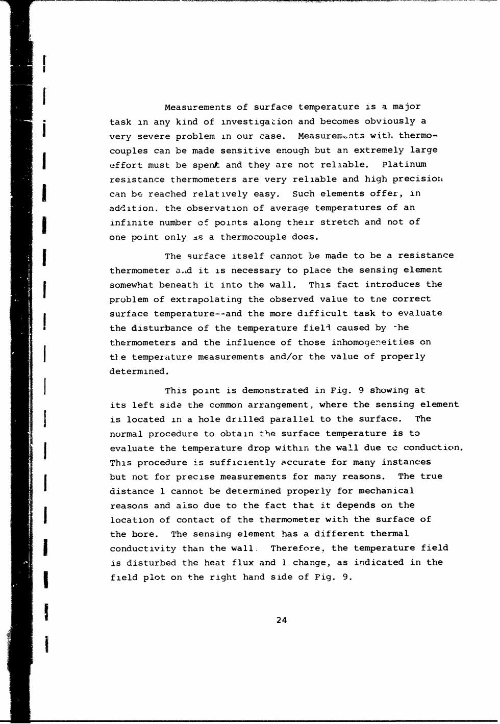
I This point is demonstrated in Fig. 9 showing at
its left side the common arrangement. where the sensing element
Sis located in a hole drilled parallel to the surface. The
normal procedure to obtain the surface temperature is to
Sevaluate the temperature drop within the wall due to conduction.
This procedure is sufficiently accurate for many instances
but not for precise measurements for many reasons. The true
distance 1 cannot be determined properly for mechanical
reasons and also due to the fact that it depends on the
location of contact of the thermometer with the surface of
the bore. The sensing element has a different thermal
Sconductivity than the wall. Therefore. the temperature field
is disturbed the heat flux and 1 change, as indicated in the
I field plot on the right hand side of Fig. 9.
24
!I

LL
_______I___
/L
----- I ! 1
FIG. 9 DISTURBANCE OF TEMPERATURE FIEL-
The thermometer located in the hole will measureany value of temperature between T! and T1 depending onwhere contact with the surface of the bore is made. If auniform contact exists circumferentially T1 would be thetemperature sensed and for this case the temperature dropwithin the wall evaluated with the wall thickness 1 wouldyield the surface temperature. For cases of temperaturereading depending on contact location, different l's must beapplied. But the surface temperature evaluated would be thetrue one only for the surface outside the range W. To obtainthe surface temperature within this range other ialues ofheat flux and 1 must be used to compute the temperature drop.
Equally good contact cannot practically beachieved and it is of advantage to surround the sensingelement (.f the thermometer with an insulating material assuringa more uniform contact resistance--for stead, state only forunsteady state measurentents insulation would be of a disadvantage.
25

f
The part of the surface area of the hot body along the
thermometer hole and of width W has a lower temperature than
I the remaining part of the surface. In the case of the cold
body, the temperature of the respective area will be higher.
Therefore, within the layer of test fluid an equally large
area exists where LT is smaller and where less heat will be
conducted. But this will be compensated for to a certain
extent by the increase in B according to equation 1. How much
the distrubances of the temperature field influence the
desired accuracy anticipated can be judged only by computing
the temperature fieid.
The disturbances obviously will be smaller the smaller
the difference is in the values of thermal conductivity of
the materials of the wall kw and the hole kh, respectively.A platinum resistance thermometer consists of wire and
insulation material and its apparent thermal conductivity,
i-e., kh is practically fixei. Uniform conditions cea. therefore,
I be proviled only by choosing the material for the wallqaccordingly. But it must be pointed out that ior this
j combination of low conducting materials the temperature drop
across the sensing element is larger than with a wall material
of hioh conductivity like copper. This is due to the fact
that two dimensional heat flow (and possibly three dimensional
heat flow for reasons of different contact resistance2 along
the hole) will have more equalizing effect on the temperature
distribution than in the case of low conducting wall mitterial.
I Despite this fact, a high nickel chrominum alley,
Nimonic 80A made by DEW, was chosen because of itsI *
The Curie-point of Nimonic materials is faroutside the temperature range of our measurements.
Deutsche Edelstahlwerke, Krefeld Germany
I26!
I

I
Iexcellent mechanical properties at high and low temperatures
and itA equally good corrosion resistance make this materidl
very suitable for the construction of the multi-purpose
instrument. Its low thermal conductivity is a drawback only
for the measurements of one property, the thermal conductivity.
but this can be overcome by using specially designed resistance
thermometers, placing them properly, and. finally, computing
the temperature field.
Proper placement means that the location of the
resistance thermometer must be definitely known in respect
to the surF ace. This can be achieved bk- enclosing the
thermometer in capillary tubes 6nade out of Nimonic 80A)
which are hard soldered into grooves cut with proper shape
and depth into the surface.
The resistance
thermometer is of the form
Pt-wire (0.15 mm 0) of a straight wire loop
.I insulated by alumina beads
as shown in Fig. 10. The
clearance of the beads
inside the capillary tube--_first te-2dN is of the order of .1mm
and less. The large0 Inumber of beads used andS: -•A203 insulators
ltthe small clearance will0 •assure that contacts are
made at dnank different
-lIost beod r locatiois lanqthwise andleads cut off after -e- in respect to the circum-sistance thermometer I -Csin place ference of the insidespcesurface. thus Ielpinj to
Pt-resistance thermometer surface, hu temperatoplaced into coiled capillary b;--neath surface o
(s5tJ~efc drawming_____________ This is supported also by
the fact that the parallel
27

[
j wires of the resistance thermometer are twisted and therefore
see similarly different locations of the enveloping material.
Cutting the grooves with a lead onto the cylindrical surfaces
of the instrument improves, in addition, the reading of the
average temperature of the total surface. The straight wire
I arrangement of the resistance thermometer and enclosing it by
materials of thermal expansion close to that of platinum
assures that the resistance the',mometer, once put in place
and properly annealed, will be subjected to least stress andJ its temperature dependent resistivity will remain constant
to a large extent.
j The technique of measuring surface temperature
just discussed yields the composite structure of the multi-
f purpose instrument shown in Fig. 11. To the Nimonic surfaces
GOLD
j WALL OF HOT BODY WALL OF COLD BODY
I -- -- - -- -- -- -- -- -- --- -
kw kw
k kAu
' J/TEST FLUIDIiI
_
1 .. D, 4r It05
jFIG. I I CROSS - SECTION OF COMPOSITE STRUCTURE
are bonded pure gold layers of 1 mv, thickness for reasons of
f keeping radiant heat transfer small, to avoid chemical
reaction with the test fluid, etc.
1 28
!

rIIiI I
The temperature field for steady heat flow was
computed by a relaxation method under the assumption that cold
and hot bodies are infinitely long cylinders. The gap
accomodating the test fluid of nominal 0.5 mm width represents
the distance between nodal points in radial directIon. The
arrangement is radially symetric and therefore only a section
like the shaded one needs to be considered: its height is given
by the lead of the capillaries enclosing the resistance thermo-
meter and the symmetry. Distances between nodal points in axial
direction have been chosen to be 1mm. For simplicities sake2
the 1 pmn circular section of the resistance thermometer was
replaced by a rectangle 0.5 x 2 mm. For the wall-thickness
of the cold bbdy of the multi-purpose instrument ccmputed in
the previous section and for a diameter of the hot body of
34 mm enclosing an electrical heater of 8 mm diameter one
obtains 1200 nodal points; i.e., 1200 equations with 1200
unknowns must be solved to obtain the temperature fibld in
the composite structure. The large number of equations, the
cylindrical geometry and the different properties involved
make it obvious that solutions can be obtained by an
iteration procedure only and only with the aid of large
computers. It might be for this reason that solutions of
the problem hape not yet been available--also for the fact
that programming by itself represents a very time consuming
task. Allision Division of General Motors Corporation in
Indianapolis fortunately had worked out a program for similar
studies and they generously allowed the use of their facilities.
This is greatly appreciated and Mr. Pyne and Mr. Colborn of
Allision are thanked for their help and work.
The computation of the temperature field was carried
out for various arrangements and especially for three different
fluids within the gap selected in respect to the range of thermal
conductivit- values to be measured with the multi-purpose
instrument.
29

I
The results of the calculations are given in
Tables 2, 3, and 4 where the temperatures of the nodal
points in the neighborhood of the surfaces of hot and cold
body are recorded. Table 2 shows the temperature field for
the case that the test fluid is of low conductivity (10
times smaller than that of water) and for a steady heat flow
through the composite structure producing one degree tempera-
ture drop in the sample.
TABLE 2. STEADY STATE TEMPERATURE DISTRIBUTION INWALLS OF INSTRUMENT ADJACENT TO SURFACESWETTED BY A FLUID (kfluid = O.1k t; AT =1C)
25 16 27 26 19 30 31 32 33 34I I I2617.1 2616 7---2615 7 2615.1 2615 ? 251415 2514.5 2514 5-251!f7 251!.3
2,11.0 2616I5-2615 7 2615.1 2615 7 251'.5 2514.5 2514 5-251!18 251!.4
2616.9 2616.3 2615 e 2615.7 2615 7 251445 2514.5 2514 4 2514.0 251!.SSI i
2616.9 2616.3 2615 8 261S.1 2615. 7 2S5144 Z5 1 5 2514. &sI 2514.0 2513.S2616.8 2616.3 2615 e 2615.1 2615 ? 2514 5 2514.5 2514 4 2514.0 2513.5
2616.8 2616.3 2615 0 2615.1 261 2514? 5 14 514.5 2514 4 2514.0 2513.5
261.6- 2616.3 261548 2615.1 2615, 2514'52I. 2514I42540 51.
2616.9 2616.3 2615 8 2615.f 2615 7 251415 2514.5 2S14 4 2514.0 2513.5
2616.6 2616.3 2615 Z 2615.f 2615 ? 2514 5 2514.5 2514 4 2514.0 25P.5
- I2616.q 2616.3 2615,P 2615.f 2615 7 251445 2514 Z 2514.C 251?.S
2616.9 2616.3 261540 2615.f 2615 7 2514'5 2514.4 2514 4 2514.0 2513.5
2616.9 2616.3 2615 e21.f 2615 5 2514 .4 251 4 25196.0 2511.5
2616.9 2616.3 2615 8 2615.t 2615 7 25144 .4 2514 4 2514.C 2513.5
2616.9 2616.3 2615! 2615.8 2615. 7 2514!5 2514.5 251Z4 2514.0 251!.5I I2616.9 2616.3 2•••2615.8 2615j7/ 2514j 5 2514.4 2514 4 2514.0 2513.5
2616.9 2616.3 2615 @ 2615.f 2615 7 251415 2514.4 2514 4 2514.0 251!.5
2616.q 2616.3 2615]t 2615.8 26i154 251445 2514.4 2514•4 2514.0 2511.5
I3251012616.9 t616.3 2615 b 2615.8 261517 2514h5 2514.4 •54•2514.0 251'.5
30
I

The nodal points are counted in radial direction
starting at the heater element of the hot body and in vertical
direction from the adiabatic line going through the thermometer.
The temperature of nodal points on this line are represented
I by the values listed directly under the numbering of the
radial subdivision. The surfaces of the hot and cold body are
T located at number twenty-nine and thrity, respectively--
indicated in the table by vertical lines, The rows of values
under these numbers represent the temperature distribution of
= the respective surfaces. The gold coat occupies the layer
between 27 and 29 and between 30 and 32. The temperature
measured by the thermometers will be an average of the values
given for the nodal points at the location indicated and by
taking into account the symmetry of the arrangement.
The temperature values are given to a thousandths
of a degree (i.e,, 2615-7 must be read 26.157*C). An inspection
of the table indicated the disturbance of the temperature
field in the neighborhood of the thermometers. The result
that the gold layer dampens that disturbance completely is
important; the surface remains isothermal. For this case
the geometric constant is identical to that one determined
by capacitance measurements. The true temperature drop within
the wall can readily be obtained from the table. This
information will be helpful to achieve a rrore accurate
extrapolation from the temperature read by the thermometer to
the surface temperature whenever thermal conductivity of
different fluids and/or under different conditions in the
gap will be determined. For this reason the computation was
rep2ated for the same substance but under a heat flow increased
by a factor of two; therefore, there is a two degree temperature
difference between hot and cold body surfaces. (This also
represents conditions within the walls one would obtain when
a fluid of twice the thermal conductix-ty is investigated.)
31

TABLE 3. STEADY STATE TEMPERATURE DISTRIBUTION INWALLS OF INSTRUMENT UDJACENT TO SURFACESWETTED BY A FLUID (k 0.1 kw; T= 2C)
fluid =wdtcr'
25 26 27 26 29 30 31 32 33 3'
2732.4 210!6_.-27291 a 2729.1 272917 2530 2530.2 253 X2--252819 252e.3
2732.2 2731I2-2729t Z729.1 2?2. 7 2530 2 2530.2 253C -2--2•29l1• Ze.5I I2732.0 2730.9 2129 8 2129.6 2729 7 2530 2 2530-2 253011 Z529.3 252e.6
2731.9 2730.9 2125 8 272.6 2Z729 8 25:0 2 2530.2 253C 1 2529.4 2526.6
2731.9 2730.9 2729 S 2?29.6 2729 8 2530 2 2530.2 253C1 2529.4 252E.7
Z731.9 2730.9 2729 9 2729.6 2729 8 253922502 SH &52;4 5e.
2T319 230. 212 9 ?29e 279 a2150tZ253C.1 253C&! I 52S.4 252e.?
2731.9 2730.9 2122919 2729.e 2729 8 56 23. 253C I 2529.4 25E.?
2731.9 2730.9 2729 9 2729.6 2729j 8 2530z2 2530.1 253C 1 2529.4 252E.7
2731.9 2730.9 2725 q 2729.6 272918 25304'2 2530.1 257C 1 2525.4 252e.?
2731.9 2730.9 2729 q 2729.i 2729 8 2530C2 2530.1 Z53C I 2529.4 252e.7
2731.5 2730.9 2729 9 2729.t 2729 8 2530 2 2530.1 253C 1 252e..4 252E.6
2731.9 2730.9 2729 9 2729.6 2729 8 2530 2 2530.1 253C 1 2529.:. 252E.6
2731.9 2730.9 2729 9 2729.t 2729 8 2530 2 2530.1 253C 1 2529.4 252e.6
2731.9 2730.9 2729J9 2729.6 2729. 2530 2 2530.1 253C11 2529*.4 251ý.6
2731.9 2730.9 272949 2(49.t 2729 253C12 2530.1 253C I 2529.4 252E.6
2731q 2"30.q272549q 729/~.6 ?qe23, 50!23 5q•Z2.
The results are given in Table 3. There it carn be
noticed that the disturbance of the temperature field is
increased and %he surfaces are no longer isothermal. But thedeviation from uniformity is small and only present in the
immediate neighborhood of the thermometer--the area influenced
is only a small fraction of the total heat transfer area. The
evaluation of the true surface temperature and of the true
temperature difference is somewhat more involved and the
32

fli9 gt.ometric constant must be corrected to a slightly highez
value. The disturbances are small, can be taken into account
and will have little influtance on the final result--the value
I of the property measured.
The two cases discussed so far represent conditionssimilar to those present in the multi-purpose instrument when
thermal conductivity of most gases, vapors and liquids are
measured. Therefore, tests with those fluids can be made with
high precision.
TABLE 4. STEADY STATE TEMPERATURE DISTRIBUTION INWALLS OF INSTRUMENT ADJACENT TO SURFACESWETED BY A FLUID (kfluid = kwater' AT = 10 C)
25 26 27 2m 2Y 3C 31 32 31 34
2762.2 27S8 2-..74C. 1 2749.C 27'R.3 2653.6 265.'4 265 3 1-2164711 2644.7II
27t1.1 2756!2 -2749 2 2749.C Z748 9 2653 5 2653.4 265? 2--24 e14 2645.4
276C.1 275. 2744 2749.1 2744 9 2653 5 2653.3 2653 1 264S.4 264!.C
2759.8 2751.5 274q 4 274q.2 2744 0 2653 4 2653.2 2653 C 264S.5 2646.2
275%.7 275S4, 274944 I'49.2 2747 0 2 6 53 4 2653.2 ?651 C 264S.6 164E.1
275S.6 2754.4 2714%# 274q.? 2744 1 2653} 3 2653.2 2653 C 264S.4 264t.3
2759.t 1754.4 274S S 27?9.- 2749 1 2653 1 2553.1 2653 C 264S.5 264E.3
275q.6 2754.4 2?4'4,S 274q.3 .1744 L 20-153 3 Z653.1 26524S 1et4q.S 2646.3
27519.7 2?5'.5 214945 274q.! '74-4 1 2654 3 2653.1 26524; 264%.5 264f.3
2759.? -154.5 274-:i 2749.? 2?'.7 126-3j 3 2653.1 26524% 264;.5 264f.3
275q.? 2754.5 2?4i;E 2749.4 2?'.1.2 265313 2653.1 265?'4 164%.5 2646.3
2~~7 2754.5 274q#_6 2749,.A 274..?2 26Sj3 Z6312e521 2849;.S 264t6.3
2?S;.1 27S4'.' 2!4q!6 2749.4 2741 226%3 2653.1 2652 64.5 J646.2
2?59,.7 2754.5 274S.6 2749.' 274j;2 265313 i653.1 265421b 2054S.5 264t.2
275%.' 2754.5 2749.6 274q.4 7'447 lc53 2 2 6 S' 1 265219 264S.5 264(.2
Z'5S.7 215-.1 2?4qiE 2749.4 27.1 z Z53F 1653.1 26S21-?41 1. ~ 64;.5 :64f.2
33

The situation becomes more difficult when materials
of high conductivity are measured. This is proven in Table 4
showing the temperature distribution in the multi-purposeinstrument when water is the test fluid and there is one
j degree temperature difference in the test layer. The surfaces
deviate now from being isothermal for an extended heat transfer
area, but practically half of it remains at a uniform temper-
ature. The corrections necessary are more severe and more
j difficult to perform but they can be made with a high degree
of certainty due to the information given by the analysis.
J The computation has been carried out with preliminary
dimensions provided by first sketches of the multi-purpose
instrument. The correct dimensions are nc~w available by the
final design and the computation will be repeated before
measurements start and they will be carried out to a ten
thousandths of a degree of the temperature values.
The determination of surface temperature together
with the evaluation of radiant heat exc.ange and lead-in losses
did represent the most severe obstacles in achieving good
precision in thermal conductivity research. The analysis
performed, the special design and fabrication will increase
the accuracy of property data measured and of all other
investigations where the surface temperature is a major
quantity and for all this it can be hoped that the benefitsresulting from it will justify the effort spent.
TI_•E NEEDED TO ESTABLISH STEADY STATEJ TEMPERLTURE CONDITIONS
The multi-purpose instrument will operate over wide
temperature ranges and the measurements of the different
properties will be made at different levels of temperature.
Changing from one level of temperature to another can be done
conveniently with the aid of the thermostat but the question
| 34

W I
remains if the new steady state conditions necessary for the
measurements can be reached in a reasonably short time--
especially in the instrument constructed out of a materialwhich has been selected because of its mechanical andchemical qualities and also, to a certain extent, because of
its low thermal conductivity. The low diffusivity of the
-. nickel-chromium alloy will influence the time needed for
heating or cooling the instrument to a new temperature level
but not to the extent its low diffussivity indicates at a
first glance. The heat transfer coefficient of the helium
flowing through the channels of the instrument has a stronger
effect. This is proven in Fig. 12. The graph given there
represents the solution of the differential equation describing
the temperature change
0 in infinitely long cylinders
3o ",'s°°•/m~h%/ heated or cooled by
,enon/ convective heat transfer
Cop•p_ [4] under the assumption
20 -that the heat transferZ hZ*3h. media remains always
h at a constant temperature.
The plot shows the time1|0- needed to decrease the
t temperature difference
between helium and
inside of the cylinder0°0 1 2 Wrl 4 (CM)to one percent of the
R'pU (CM)
FIG 12 TRANSIENT HEATING OF CYLINDERS original value and when
the cylinder oriqi:-:a lly
was at a uniform temperature.
The time needed is plotted versus size of thecylinder made out of copper and Nimonic for two different
heat transfer conditions. For a heat transfer coefficient of
about 500 kcal/m/h 0 C a copper cylinder of 50 mm radius would
reach the new temperature level in 11 minutes--the Nirnonic
.35
I
It
cylinder in nineteen minutes. Not even twice the time is
needed to heat the body of twenty time.. lower diffusivity.
For three times higher heat transfer coefficientand for the same geometry the times needed would be four andeleven minutes respectively. For an infinitely high heattransfer, a Nixnonic cylinder would need twenty fold more timethan a copper cylinder--but this is practically of rno concern
since the absolute times involved are small anyl-ow.
The same holds true for the case of lower convectiveheat transfer because the waiting time to achieve otherconditions for new measurements is smaller than the time needed
to prepare for the new observations. Not taken into account
is the time needed by the thermostat to change the temperature
of the NrAium to a new level. This will not influence theconditions to a large extent because in a normal case helium
and the instrument will be heated or cooled simultaneously.
Everything aescribed so far discussed the necessary
steps to be tal.en- to extend the capability of a thermalconductivity cell to that of a multi-purpose instrument and
demonstrated the approaches needed to achieve reliable
measurement of the different properties. This discussion alsoproved that a design of such an instrument was feasible but
this does not necessarily mean that it can be built--especially
in respect to the centering rod--the most critical and
important part of the apparatus. Therefore, the task to beperformed before work on the design could be started was to
investigate the possibilities of fabricating the centering rod.
THE CENTERING ROD
The centering rod has to fulfill many and partiallyj contraversial requirements as already was stated briefly. It
encloses all lead-in wires to the hot body and must be built
as a double electrical shield for electrical reasons. It
36I

X
must be thin walled and of small cross-sectional area in order
r to minimize heat losses from the hot body. (For the samereason there -hould be a certain amount of heat generated
within the centering rod.) it must be strong enough to
withstand outside pressure up to 500 atm and 650*C and it
must be able to resist buckling under heavy axial loads.
Last but not least, it must have a thermal expansicn coefficient
identical or at least close to that of the material of the
cold body surrounding iL ( as discussed on page 8). Converting
the thermal conductivity cell to a multi-purpose instrument
could not be done when the e&ectrical requirement of double
electrical shielding was impossible to achieve. Therefore.
the point had to be considered first. Electrical shielding
requires a combination of conductiig and insulating materials.
The pressure and temperature ranges choosen for the operation
f the instrument necessitates the use of high-strength metals
and ceramic. The latter must have excellent electrical and
mechanical properties and, in addition, equally good chemical
resistivity. Alumina of high purity fulfills those requirements.
Combining this ceramic %ith a metal to achieve pressure leak-
proof conditions for all temperature ranges needs a hard soldering
process, This soldering can be done only when the thermal
expansion coefficients of the two components match over the
range of temperature. Iron-nickel-cobalt alloys fulfill this
requirement closely, and the best combination for our range
of temperatures is Vacon 70 of Vacuun.-schmnelze, Hanau and A18
type aluminumodyd (88%) of Stemag, Lauf. Making the metallic
Vacon 70 parts thin walled and of a shape which allows some
spring actton assures perfect combinations even when the
thermal expansion coefficients are not perfectly identical.
The aluminum oxide insulators hard soldered to
Vacon 70 matefial occupy a certain length of the centering
rod ar2 for this length the thermal expansion coefficient is
much smaller than that of the material of the cold body. To
37

fulfill the requirements of least heat loss from the hot
body it was necessary to make the connecting tube thin walled
and this in turn dictated the selection of the material for
reasons of strength. Nimonic 90 was chosen but this material
also has a thermal expansion coefficient that is smaller than
Nimonic 80A. In order to compensate for the difference it
was necessary to use for the extension of the centering rod
another material, ATS 15, having a thermal expansion coefficient
much higher than that of Nimonic 80A and to select the length
of the Nimonic 90 ani ATS 15 parts so that for the total
length of the centering rod a thermal expansion coefficient
obtained is equal to that of Nimonic 80A. This will be equal
only for a certain temperature condition. For other temperatures
there cannot be a perfect match for the simple reason that
the temperature dependence of thermal expansion coefficients
of the materials involved are not identical. But they are
similai and therefore the centering rod will change its
lengtxh wi' h temperature not much differently than the cold
body does, and only a small displacement of the hot body in
respect to its surroundings will occur. This will change the
geometric constant, but this will be measured and its. true
value will be known at any temperature as discussed on page 8.
The increase of inhomogenities will be of little effect on the
property determinations. The small difference in thermal
expansion is equally important to assure that the hot body
never can be displaced within its surroundings to such an
ey*ent that contact with the cold body occurs which would make
measurements impossible and damage the instrument.
Combining the different metallic parts (most of
which are thin w;alled) can be dcne only by electron-beam
welding. The feasibility of the construction just discussed
was tested on a pilot device and then designed. This did lead
to the arrangement shown in Fig. 13. The centering rod is
38

ff I r-
VA (AMS 240)
I vc SOASMx
I Ooft wWP~-LWnIjGMA A~I
2OSS >D -I ISA~n -~~~
Iim D EOWSA
AIO All~
I oo 70O~*,~ .
~w jOWSSA~ i~SS~oigfST4ThG NM '
--------------
Iw 90 3Q)[XW~e2 4~d ~S~
liti
KOG 70 A* Mat
fm 70
FIGURE~ 13. CENTERING ROD
39

I
I
o
perfectly aligned and attached to the hot body by means of its
base held in place by a screw arrangement. The centering of
the hot body within the cold body's cavity is achieved by a
honed hole in the axis of the cold body accomodating the
cylindrical extension of the centering rod with least clearance.
Pressure tight seal is provided by a 60* tapered seat and a
gold gasket of a thickness chosen in respect to the proper
placement in axial direction and to achieve the setting where
minimum value of capacitance was observed. Sealing forces
onto the gasket are applied by means of a sleeve and screw
allowing the centering rod to be pulled in an upward direction
(these are not shown in Fig. 13).
The tube 1505 and its extension 1506 shield the lead-
in wires and are shielded themselves by tubes 1510 and 1511
in order to accomolish the electrical measurements as discussed
previously.
Fig. 13 is a reproduction of the assembly drawing
of the centering rod. On the left hand side are given the
numbers of the parts and the respective materials they are
made from and also the vendors and/or producers of the
materials. On the right hand side are listed the necessary
steps to be taken to construct the centering rod.
THE FINAL DESIGN OF THE INSTRUMENT
The design of all the other parts of the multi-
purpose instrument was somewhat less involved than the develop-
ment of the centering rod and lead to the apparatus shown in
Fig. 14. Thp cross sectional view represents the reproduction
of the engineering drawing somewhat modified for easier reading.
The instrument consists of four major parts: the hot
body and the three parts assemblirg the cold body. The cold
body has two cavitLes--the upper one of proper shape to
40

/
inner contour of pressure i Ivessel I
/ .test fluid
feed-in Jevice
KIIayer of test
centering rod fluid 0.Smm
he .... °- --ent thermostat-!i~~ //luid
Pt-resist. thermom. __ __ -- Zencl. in coiled capillary " Qoki sheath
Pt-resistance thermom. I----- - t" iPtAu-ailoy
p-re-sure-measurngdevice
valve ariangement ->_
bottom closure of .....pressure vessel 3 :
20 4, 60 80 3 bD 2C m
electric sheld - - L-" 2.....0.......
FIGURE 14. MULTI-PURPOSE INSTRUMENT
41

accomodate the hot body and the lower one of spherical shape
added to increase the volume used and also to enclose a
standard platinum resistance thermometer. This is needed to
measure the temperature of the fluid tested and to calibrate
the resistance thermometers placed in the capillary tubes
as was discussed on pages 21 through 34 of this paper. On
the outer surfaces of the three parts of the cold body are
cut the passages for the thermostating fluid. The channels
between the different parts are connected by vertical and
horizontal bores.
The three parts of the cold body are centered to
each other and held together by means of ring nuts. Sealing
forces are applied with the aid of screws in the ring nut and
act on gold O-rings placed between the parts at proper locations.
All surfaces in contact with the test fluid are made of
inert material bonded by a special process to the base metal.
This material is gold for most of the area but a gold
platinum alloy at those locations where sealing forces will
be applied and where inertness and mechanical strength are
required.
The lower part of the cold body accomodates twovalve seats and the vapor pressure measuring device. This
device is not used for the valve arrangement shown. The
test fluid in this case is in contact with outside instrumenta-
tion. For isochoric measurements another valve stern will be
inserted which allows the instrument to be evacuated in an
open position and is seated so that the vapor pressure
measuring device is connected with the test fluid. The
pressure transmitter is always at the sample temperature:
therefore, pressure changes due to condensation and/or
evaporation will not occur.
The upper part accomodates the centering rod and devices
for flushing the instrument or to feed-in a well known mass of the
sample especially for the determination of p--v-T relations.
42

IIk
A
F IGMURE 15. MU~ PROEINSTRUMENTASSE14B&2D
43

The hot body, held and centered by the centering
rod at its upper nd, is centered also at its lower end by
means of a cente ng pin made of pure alumina. Fig. 14
demonstrated also the mounting, insulating and shielding
of the instrument.
All the parts of the apparatus have been machined--
the only task remaining is attaching the gold lining. The
multi-purpose instrument assembled is shown in Fig. 15.
The design of the major parts and their construction
and operation wili be discussed in detail in a successive
paper. Another paper will deal with the measureiments and
error analysis of the pronerties determined.
ACKNOWLEDGMENTS
The work described in this paper was sponsored by
the United States Air Force Office of Scientific Research
Office of Aerospace Research under contract no. 49(638)-1574with Pardue University, The funds granted made possible the
whole investigation and the utilization of findings of
previous analysis and finally the development of the multi-
purpose instrument. These are gratefully acknowledged as
are also the stimulating discussions with Dr. I.F. Masi of
this organization. The author also wishes to express hie
gratitude to the United States Army Research Office who
permitted work on their research contract to be held in
abeyance so that the instrument could be designed during a
leave of absence. The auth-.r is also grateful to Purdue
University for making this leave possible. With great
appreciation, I thank Profs. Drs. Kersten and Moser,
President and Vice President of Physikalisch Technische
Bundesanstalt in Braunschweig, Germany for their permissionf to work as a guest at their institution and Prof Dr. Fritz,
director of the thermodynamic section of PTB, for his
44
I

lF
arrangements and help and also ORR. Dr. Steiner, director of
the Hauptwerkstatt of PTB, for the many helpful discussions
and generous support given by the skilled staff members of
the central machine shop, Thanks to their excellent work,
the designing was achieved in time and the instrument was
build in addition. Many PTB staff members contributed to the
fabrication of the apparatus. Their contribution will be
part of the following publication.
The author also wishes to extend his gratitude to
his colleague D. Tree who assisted in performing part of the
analysis and to P. Liley for his encouraging discussioihs and
to other staff members and students for their support; to
Mr. K-ker and Mr. Mannl of Technical University Braunschweig
for copying and inking the author's pencil sketches and
design drawings and producing the final engineering drawings.
Pilot devices and the instrument could not have been built
within the relatively short time without the help and
assistance of several factories and their representatives.
Special materials in small quantities were furnished with
least delay on request and special work was performed. The
author would lixe to thank Prof. Dr. K. Bungardt, director
of Deutsche Edelstahlwerke, and his assistants; Drs. Loebich,
Roters and Meixner of Degussa; the late Mr. Schabbeck and
his successor of Stemag, the Vacuum-schmelze for providing
Va,-:n 70 alloys and Dr. Jung of Steigerwald Strahltechnik
for perfomzing the electron beam welding.
REFERENCES
1. W. LEYDENFROST, An attempt to measure the thermalconductivity of liquids, gases and vapors with ahigh degree of accuracy over wide ranges of temperature(-180*C to 500*C) and pressure (vacuum to 500 atm),Int. J. Heat and Mass Transfer 7, 447-478 (1964).
45

2. M. C. McGREGOR, I. F. HERSH, R. D. CUTKOSKY, F. K. HARRISand F. R. KOTTER, New apparatus at the National Bureauof Standards for absolute capacitance measurement,JRE Trans. on Instrumentation vol. 1-7, 253-261,Dec. 1958.
SE. 0. SChMIDT and W. LEIDENFROST, Optimierung einesadiabatischen Kalorimeters zur genaueu Messung vonwahren spezifischen Wdrmen schlecht warmeleitenderSubstanzen, Int. J. Heat and Mass Transfer 5, 267-275 (1962).
4. MAX JAKOB, Heat Transfer, Vol. 1, p. 285, Wiley, New York(1959).
t
4
1 I
I
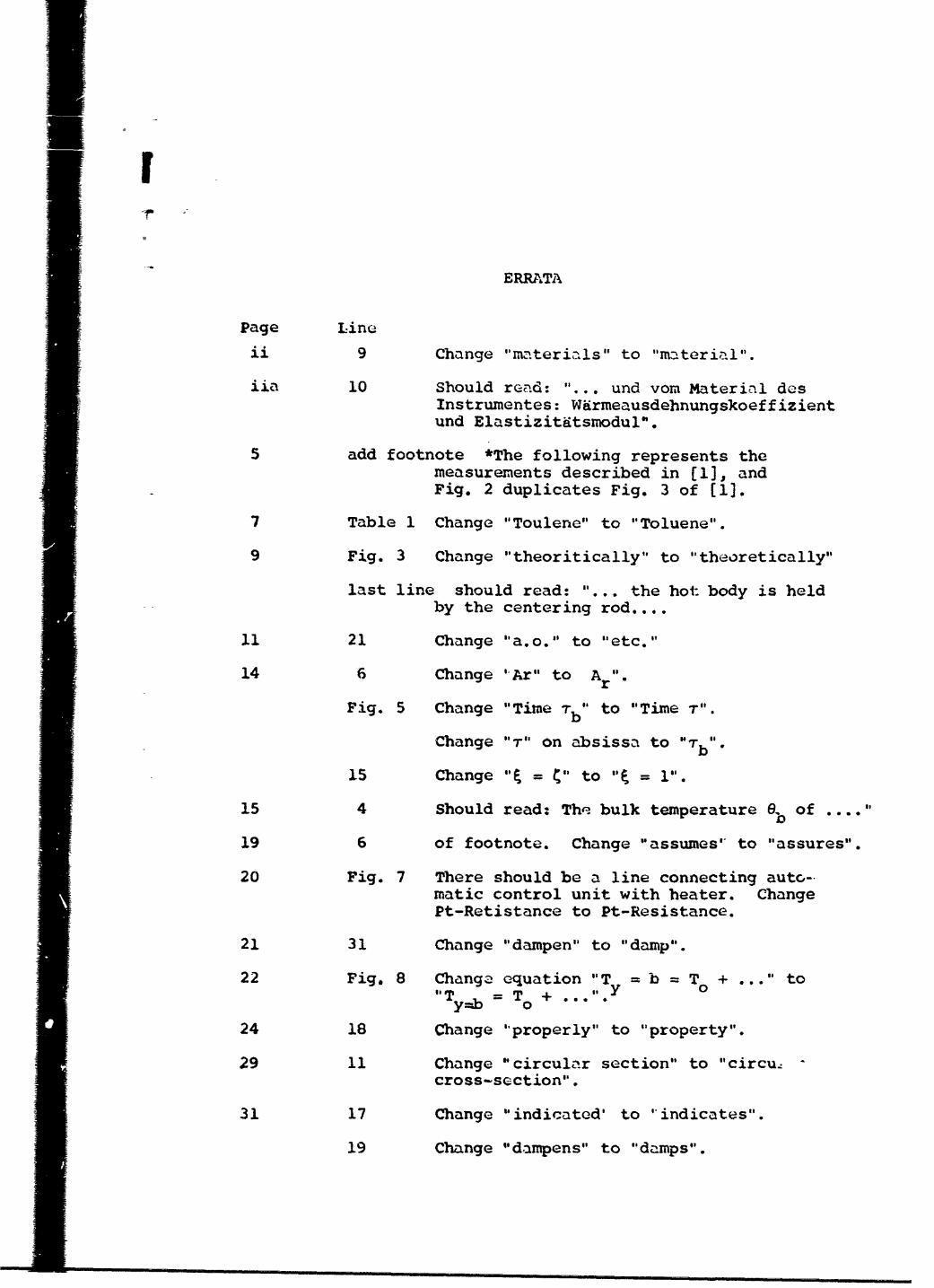
iI
ERRATA
Page Linn
ii 9 Change "materials" to "material".
iia 10 Should read: "... und vom Material desInstrumentes: Wdrmeausdehnungskoeffizientund Elastizitatsmodul".
5 add footnote *The following represents themeasurements described in [1], andFig. 2 duplicates Fig. 3 of [1].
7 Table 1 Change "Toulene" to "Toluene".
9 Fig. 3 Change "theoritically" to "theoretically"
last line should read: "... the hot body is heldby the centering rod....
11 21 Change "a.o." to "etc."
14 6 Change 'Ar" to Atr
Fig. 5 Change "Time Tb" to "Time T".
Change "T" on absissa to "Tb%
15 Change "'I = C" to "t = 1".
15 4 Should read: The bulk temperature e, of .... "
19 6 of footnote. Change "assumes' to "assures".
20 Fig. 7 There should be a line connecting auto-matic control unit with beater. ChangePt-Retistance to Pt-Resistance.
21 31 Change "dampen" to "damp".
22 Fig. 8 Change equation "Ty = b = To + ... " to'Ty__b = T0 + , #
24 18 Change "properly" to "property".
29 11 Change "circular section" to "circu-cross-section".
31 17 Change "indicated' to 'indicates".
19 Change "dampens" to "damps".
-2-
37 15 Change "choosen" to "chosn'".
27 Change "aluminumodyd (88%) to"31luminux.-ioxido (98%).
44 4 Change "dcmonstrated" to "demonstrates".
I
II. M • • mm ] ~ wm rm ~~ • m i m •

71% UNCLASSIFIEDSecuity cIessictio.! • _ "DOCUMENT"CONT1*OI• DATA*- R & D0
• • -I . ORIGINATING ACTIVITY (Cwp ora i uther) RENPORqT SKCUZTY CLASSIFICATION
Purdue Research Foundation INCLAA•TJE
Mechanical Engineering DepartmentLafayette, Indiana 47907
3. REPORT TiTLE
THEORY AND DFSIGN CONSIDERATIONS IN DEVELOPING A MUTI-PURPOSE
INSTRUMENT FOR DETERMINATION OF TWELVE PROPERTIES
4. DESCRIPTIVE NOTES (?"Wpeatf IWO! and iftluadvo dm100)
Scientific InterimS. AU THORMS (Pdrleat mfdea initial. last naem)
W. Leidenfrost
RE. rPORT DATE 7, TOTAL NO. OF PAGES 7b. NO- OF REPSS46 4September 1966
Sh-4L CONTRACT OR GRANT NO. W. ORISINATOWS REPORT NUNSERISI
AF 49 (638)-1574K h. ,ROJECT NO. 9750-01
S61445014 OTHER REPORT MOM (Aot DOW ,oM N o1 n.I•Y M, A-, assigned6 4 0 this report)
d. 681308 AFOSR 67-255110. DISTRIBUTION STATEMENT
1. Distribution of this document is unlimited.
ii. SUPPLEMENTARY NOTES 12. SPONSORING MILITARY ACTIVITY
K AF Office of Scientific Research1400 Wilson Blvd. (SREP)
ThArlington, Virginia 22209
The development of a new instrument is described and also techniquesof measurement to determine;, for fluids: 1) thermal conductivity,2) dielectric constant, and hence 3) index of refraction, 4) electri-cal conductivity a.c., 5) electrical conductivity d.c.; for gasesand vapors: 6) p-v-T properties; for liquids: 7) therrmal expansioncoefficient, 8) compressibility, 9) vapor pressure, 10) specific heatc •, 11) specific heat c ; for solids: 12) specific .- t; and forf1strument materials; dermal expansion coefficient and Young'smodulus. A new thermostat operating from about -190*C to 650*C is-described. This device is controlled automatically and can followpze-set temperature-time functions. Detailed analysis is made for theprocedure necessary to establish isothermal conditions at surfaceswetted by the test substances and to evaluate deviations from suchconditions due to the disturbance of the themperature field in theneighborhood of the surfaces caused by the temperature sensing elementThis also is important so tha.t the correct surface temperature can bederived from the readings of the thermometer. The construction of thecentering rod (the most critical part of the multipurpose instrument
S~being a double electrically shielded lead-in and a centering device)is described as is also briefly the final design of the apparatus.
S DD I"tV s 473 TrTq4TT~
beig adobleelctrcaly hiede.led-iad ace terin dvce

I iI__ _ _ _i_ _.L.....
Properties over wide anges of pressureand temperature
Thermal conductivity
Dielectric constant
Index of Refraction
Electrical conductivity (a.c.)
Electrical conductivity (d.c.)
Thermodynamic p-v-T properties (gasesand vapors)
Vapor pressure of liquids
Compressibility of liquids
Thermal expansion coefficient of liquids.
Specific heats of liquids
Specific heat of solids
Thermostat, calorimeter
Multi-Purpose instxument !
AM=A
Z
II I
I!I!
I|
II
Ij I ! Ii
ii Ii I______Li m nfe~f.3RTT~f
Secualy ~asiiedto~s