i designing of manifold system for lpg and industrial...
TRANSCRIPT

i
DESIGNING OF MANIFOLD SYSTEM FOR LPG AND INDUSTRIAL GAS AT
FKKSA’S LABORATORY
MOHD RIZUWAN BIN ABD WAHAB
A report submitted in partial fulfillment of the
requirements for the award of the degree of
Bachelor of Chemical Engineering (Gas Technology)
Faculty of Chemical Engineering & Natural Resources
University Malaysia Pahang
NOVEMBER, 2010
45
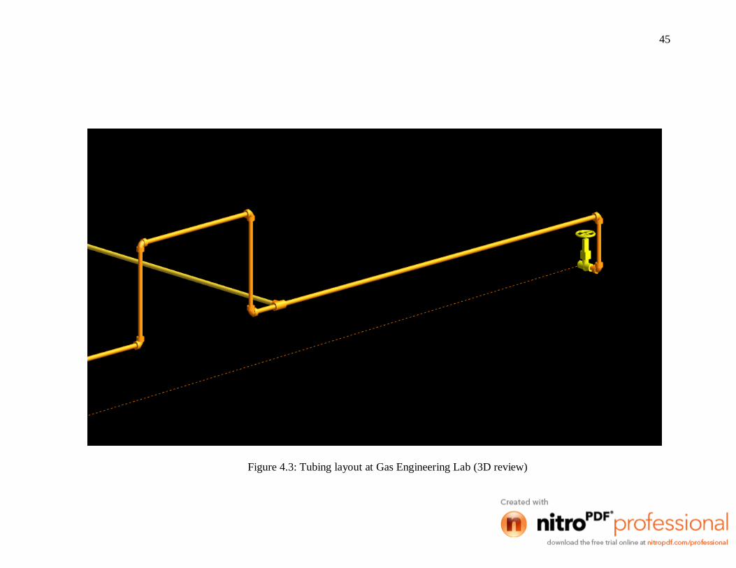
Figure 4.3: Tubing layout at Gas Engineering Lab (3D review)
46
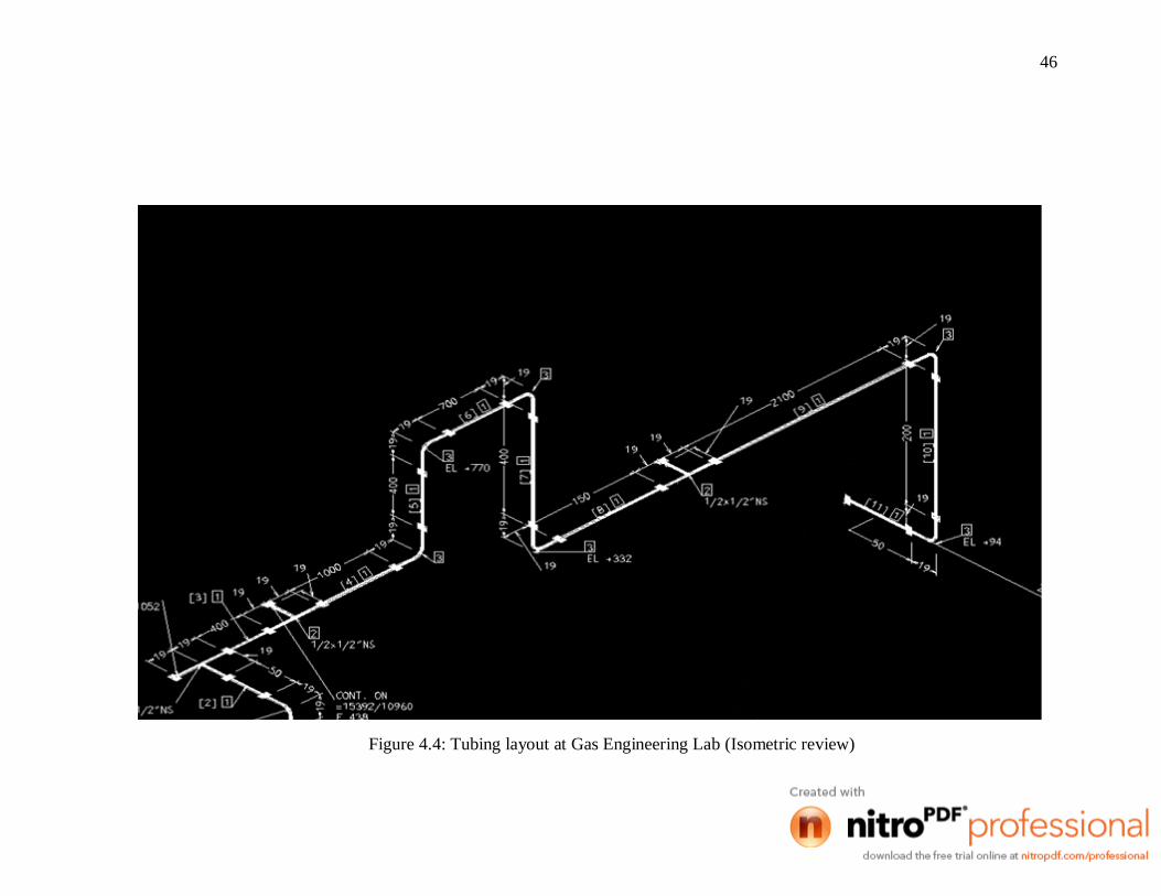
Figure 4.4: Tubing layout at Gas Engineering Lab (Isometric review)
47
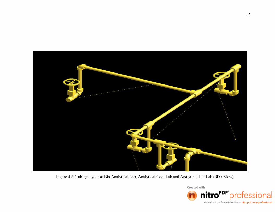
Figure 4.5: Tubing layout at Bio Analytical Lab, Analytical Cool Lab and Analytical Hot Lab (3D review)

48
Figure 4.6: Tubing layout at Bio Analytical Lab, Analytical Cool Lab and Analytical Hot Lab (Isometric review)

49
Figure 4.7: Tubing layout at Biotech Lab 2 (3D review)

50
Figure 4.8: Tubing layout at Biotech Lab 2 (Isometric review)

51
Figure 4.9: Tubing layout at Unit Operation Chemical Reaction and Separation Lab (3D review)

52
Figure 4.10: Tubing layout at Unit Operation Chemical Reaction and Separation Lab (Isometric review)

53
Figure 4.11: Tubing layout at PERKASA Building (3D review)

54
Figure 4.12: Tubing layout at PERKASA Building (Isometric review)

35
Table 4.1: The gas consumption by the equipment in FKKSA laboratory

vii
TABLE OF CONTENT
CHAPTER TITLE PAGE
TITLE PAGE i
DECLARATION OF ORIGINALITY
AND EXCLUSIVENESS ii
DECLARATION iii
ACKNOWLEDGEMENTS iv
ABSTRACT v
ABSTRAK vi
TABLE OF CONTEN vii
LIST OF FIGURE x
LIST OF TABLE xii
1 INTRODUCTION
1.1 Introduction 1
1.2 Problem Statement 2
1.3 Objective of the Project 3
1.4 Scope of Research Work 3
1.5 Rational and Significance 4
1.5.1 Rational 4
1.5.2 Significance 4
2 LITERATURE REVIEW
2.1 Introduction 5
2.2 Gas manifold System 6
2.3 Gas Cylinder 10
2.3.1 History 11
2.3.2 Types of Gas Cylinder
12

viii
2.3.3 Material Construction and Properties 13
2.3.4 Specification Number and Service Pressure 14
2.3.4.1 Specification Number 14
2.3.4.2 Service Pressure 15
2.3.5 Uses of Gas Cylinders 16
2.3.6 The Main Hazard 17
2.3.7 The Main Cause of Accidents 17
2.3.8 Safe Storage, Handling and Use 18
2.3.8.1 Guidelines to Store Cylinders 18
2.3.8.2 Guidelines to Transport Cylinders 19
2.3.8.3 Guidelines to Use Cylinders 20
2.3.8.4 Maintenance of Gas Cylinders 21
2.3.9 Maintenance of Gas Cylinder and
Associated Equipment 21
2.4 Liquefied Petroleum Gas 23
2.4.1 Comparison between LPG and
Natural Gas 24
2.5 Industrial Gas 24
2.6 Tubing System 26
2.7 Plant Design Management System (PDMS) Software 27
3 METHODOLOGY
3.1 The Overall Methodology 28
3.1.1 Estimation of Load Demand 28
3.1.2 Calculation number of gas cylinder
based on gas demand 29
3.1.3 Network study to identify length of tube 29
3.1.4 Study of suitable area to locate the gas
manifold 29
3.1.5 Assessment in term of safety at the gas
manifold area 30
3.1.6 Proposed the location and selection of
Material for the tubing system 30

ix
3.1.7 Design the layout using PDMS software 30
3.1.8 Safety analysis 31
4 RESULT AND DISCUSSION
4.1 Result 32
4.2 Discussion 38
4.2.1 Manifold System 38
4.2.2 Location of Manifold 39
4.2.3 Material Selection for Gas Tubing System 41
4.2.4 Design of Tubing System 42
5 CONCLUSION AND RECOMMENDATION
5.1 Conclusion 55
5.2 Recommendation 56
REFERENCES 57
APPENDICES 59
x
LIST OF FIGURES
FIGURE NO. TITLE PAGE
2.1 Multi Cylinder Connection System 6
2.2 Cylinder Manifolds 7
2.3 Bundle Manifolds 7
2.4 Multiple Cylinder Headers 8
2.5 Label of Specification and Service
Pressure of Gas Cylinder 16
2.6 Simulation of Piping System using
PDMS software 17
3.1 Flow chart of the methodology 31
4.1 The minimum distance of gas manifold
from the door and window 40
4.2 The flow of gas in 2D drawing
at the laboratory 43
4.3 Tubing layout at Gas Engineering
Lab (3D review) 45
4.4 Tubing layout at Gas Engineering
Lab (Isometric review) 46
4.5 Tubing layout at Bio Analytical Lab,
Analytical Cool Lab and Analytical Hot
Lab (3D review) 47
4.6 Tubing layout at Bio Analytical Lab,
Analytical Cool Lab and Analytical Hot
Lab (Isometric review) 48
4.7 Tubing layout at Biotech Lab 2
(3D review) 49
4.8 Tubing layout at Biotech Lab 2
(Isometric review) 50

xi
4.9 Tubing layout at Unit Operation
Chemical Reaction and Separation
(3D review) 51
4.10 Tubing layout at Unit Operation
Chemical Reaction and Separation
(Isometric review) 52
4.11 Tubing layout at PERKASA Building
(3D review) 53
4.12 Tubing layout at PERKASA Building
(3D review) 54

xii
LIST OF TABLE
TABLE NO. TITLE PAGE
4.1 The gas consumption by the equipment
in FKKSA laboratory 35
4.2 Heat of Vaporization and Evaporation
Rate of Each Gas 36
4.3 Number of Gas Cylinder Required For
Manifold System 37

1
CHAPTER 1
INTRODUCTION
1.1 Introduction
Manifolds are used to connect two or more cylinders of gas together
increasing the supply volume available to provide a continuous flow when one
cylinder is not sufficient and a tube trailer or other bulk supply is not practical.
Manifolds are also used when a single cylinder of gas is not capable of supplying the
required flow rate required by a process. In a single row configuration designed,
manifolds are commonly fabricated for wall mounting with a row of cylinders in line
beneath or in front of it. Double row manifolds and other custom configurations are
available on request.
Beside that, to isolate individual cylinders on a manifold from service, the
station valves are used. As recommendation, station valves are required for most
laboratory applications as they are a valuable back up device in the event of a leaking
pigtail or a defective check valve. Other than that, in high purity gas service it is
most important that station valves used to maintain gas purity. Many commercial
manifolds use packed valves that may cause atmospheric impurities to enter the gas
stream as contaminants.
Usually, it has two types of pigtails to connect cylinders to the manifold
header. Type one call is rigid pigtails made from brass or stainless steel tubing and
type two or flexible pigtail made from stainless steel braided hose with either Teflon-
lining or stainless steel inner core. Additional, Teflon-lined pigtail are used for
2
routine applications while the stainless steel inner core pigtails are used for ultra high
purity applications. More important information, either rigid pigtails or stainless steel
inner core flexible pigtails are recommended for helium and hydrogen because these
gases will diffuse through the wall of a Teflon-lined pigtail.
Check valves on the cylinder end of each pigtail must be always installed on
manifolds used for flammable, toxic and corrosive gases. In some cases, to ensure
that highly toxic gases are not released to the working environment during cylinder
change outs, the purge assemblies are installed. Many applications required the
highly toxic gas are always be supplied to the process. The flow of that gas can not
be shut down or stop to replace empty cylinders and gas must feed for long periods
when the system is unattended. In this case, a changeover manifold is the solution.
Changeover manifolds can be used with any of the multiple station manifolds or with
a single pigtail on each side.
The multi cylinder connection system, the system where is essentially
modified version of manifold system, required two cylinders with one instrument.
For example such as cylinder and bundle manifolds, bundle manifolds, multiple
cylinder headers and manifold tutorial. It can be used all at a time or one at a time by
only opening and closing the valve. This will simplify the operation and also
improves the life of the regulators.
1.2 Problem statement
Currently, Universiti Malaysia Pahang has several laboratories which
required Liquefied Petroleum Gas (LPG) and industrial gas to run the experiments
and other work related to the use of these gases. FKKSA’s laboratory are divided in
several areas where the certain areas are required the LPG and industrial gas to run
various equipment which use for student training during laboratory session.

3
The equipments which use LPG and industrial gas are required continuously
supply of these gases. So, the manifold system shall be install to ensure that the LPG
and industrial gas can be supplied without interruption such as running out of the gas.
Beside that, to install the manifold system, safety aspects should be prioritized
according to standards and code such as MS 830, MS 930, DOSH and Suruhanjaya
Tenaga Guidelines. Additional, the selection of the suitable area must be considered
as not all areas can accommodate the gas cylinder.
1.3 Objective of the project
1. To design the manifold system of LPG and industrial gas for FKKSA
laboratory.
2. To analyze or study the safety aspect.
1.4 Scope of research work
1. The gas demand
Gaseous used by various equipments at the lab and type of gas that use at
FKKSA Laboratory.
2. Safety aspect
Data, rules and regulation was based on DOSH, Malaysian standards and
Suruhanjaya Tenaga Guidelines.
4
1.5 Rationale and Significance
1.5.1 Rationale
The manifold system should be install to ensure that the gas can be supply
continuously for the equipments.
1.5.2 Significance
To avoid the problem when run the equipment that used the gas such as
running out of the gas.

5
CHAPTER 2
LITERATURE REVIEW
2.1 Introduction
These studies are focus on the designing the manifold system of LPG and
industrial gas for FKKSA laboratory and do the safety assessment. The gas manifold
system basically consist the elements like gas cylinder, tubing system, valve,
regulator and more. Zainal (2003) has state that gas manifold is use for domestic
user, commercial and light industrial. In the engineering lab, where rate of gas
consumption is high and it is much advantageous to use a manifold system. So, the
capacity of manifolded cylinders must be determined such that enough gas is
available to be piped to the appliances at all times. The tanks should be sized such
that adequate pressure is maintained to operate the gas system at the rated gas
demand of the appliances. Tank sweating will occur when the container is undersized
(Suruhanjaya Tenaga).
Beside that, the safety aspect also should be considered because it involved
the gas cylinder and flammable gas such as the location, range between the gas
cylinder, the type of gas use and more. Other than that, the safety aspect is very
important if we want to handle the gas cylinder and shortly, it related to the gas
cylinder. It is because for to ensure the worker and public safety are always
guaranteed. Before we go to discuss about the safety, we must know or have some
information about gas cylinder that use in manifold system such as its properties,
type, the material to design gas cylinder, the shape of gas cylinder and more.

6
Many people mention that the accommodation of gas cylinder is very simple
things and does not look to the safety aspect. In reality, we must follow the standards
and all rules and also all matters must be consider to accommodate the gas cylinder
and will not harmful to consumers, the public and employees. It is because to avoid
any accident to occur such as explosion when the gas cylinder is leakage.
2.2 Gas Manifold System
Manifolds and manifold systems are fluid-distribution devices. They range
from simple supply chambers with several outlets to multi-chambered flow control
units including integral valves and interfaces to electronic networks. Applications,
port specifications, flow and pressure specifications, manifold circuit style and valve
specifications are all important parameters to consider when searching for
manifolds. Additional specifications to consider for manifolds and manifold systems
include communication network, body materials, features and operating temperature.
Other than that, the manifold system also known as the multi cylinder
connection system and it divided in several types. The example of multi cylinder
connection as in Figure 2.1. It consists three of types such as cylinder and bundle
manifolds, multiple cylinder headers and bundle manifolds as in the Figure 2.2,
Figure 2.3 and Figure 2.4.
Figure 2.1: Multi Cylinder Connection System (Source: Globalspec website)