i. determination of the heating element parametershome.agh.edu.pl/~waradzyn/instruction - resistance...
TRANSCRIPT

AGH University of Science and
Technology in Krakow
Department of Power Electronics
and Energy Control Systems
Made by:
Electoheat - laboratory
Title of exercise:
Design of medium-temperature spiral resistance heating elements
for a 3-phase resistance furnace Date:
Date of assessment:
Rate:
Introduction
Task:
Design medium-temperature resistance heating elements in the form of a spiral (Fig.1) for
a 3-phase resistance furnace of a given power P (value of power given individually to each
student). The furnace is supplied from a 3-phase 230/400 V line. The heating elements should
be made of a Kanthal A-1 round wire. Assume the temperature of the heating element equal
to 1200°C.
It should be assumed that three equal spiral elements will be used, each supplied with 400
V. Assuming additionally the supply line voltages symmetry and load symmetry, the task is
limited to making calculations only for a single heating element generating power P/3.
Parameters of Kanthal A-1 round wires are given in Fig.2 and Fig.3.
Fig.1. Spiral heating element
I. Determination of the heating element parameters
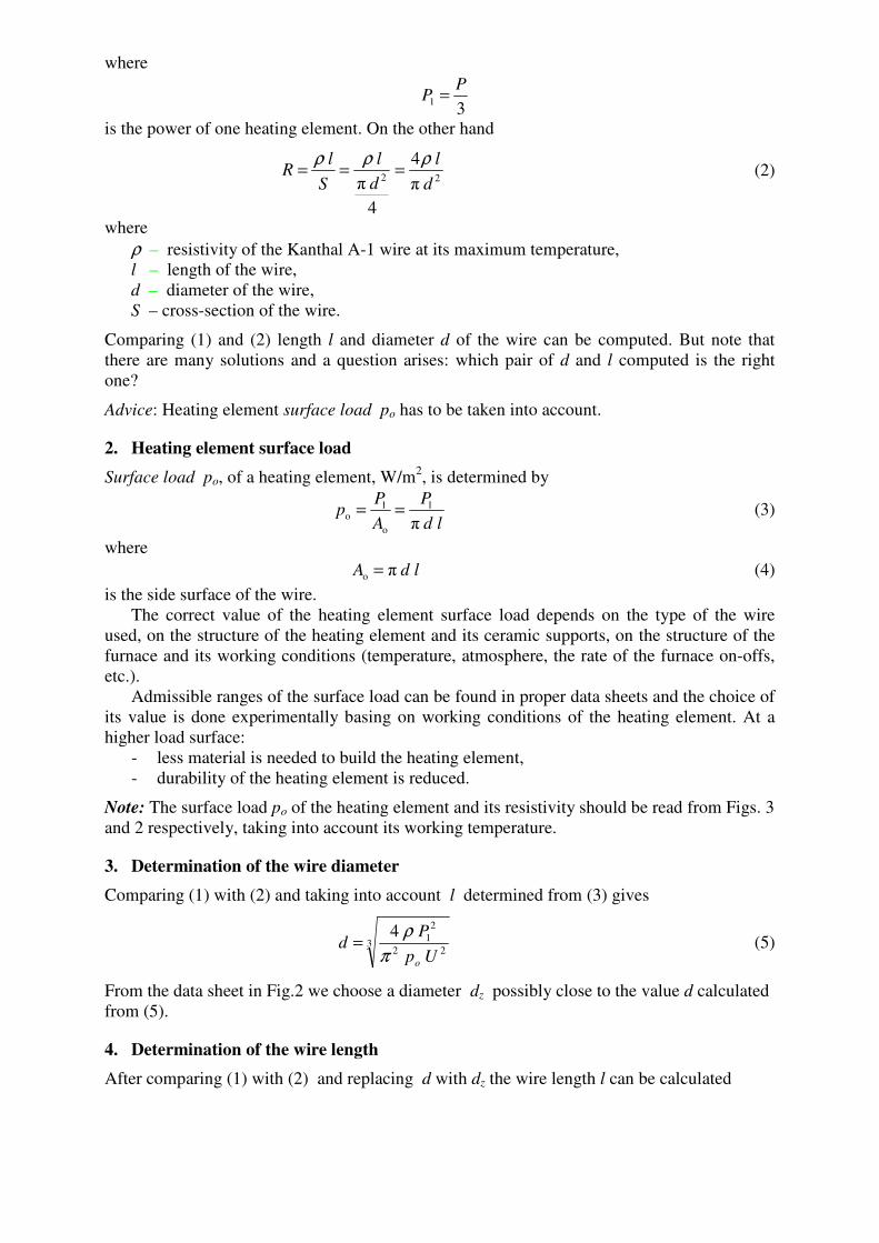
1. Resistance R of a (single) heating element
On the one hand
1
2
P
UR = , (1)
where
31
PP =
is the power of one heating element. On the other hand
22 π
4
4
π
d
l
d
l
S
lR
ρρρ=== (2)
where
ρ – resistivity of the Kanthal A-1 wire at its maximum temperature,
l – length of the wire,
d – diameter of the wire,
S – cross-section of the wire.
Comparing (1) and (2) length l and diameter d of the wire can be computed. But note that
there are many solutions and a question arises: which pair of d and l computed is the right
one?
Advice: Heating element surface load po has to be taken into account.
2. Heating element surface load
Surface load po, of a heating element, W/m2, is determined by
ld
P
A
Pp
π
1
o
1o == (3)
where
ldA πo = (4)
is the side surface of the wire.
The correct value of the heating element surface load depends on the type of the wire
used, on the structure of the heating element and its ceramic supports, on the structure of the
furnace and its working conditions (temperature, atmosphere, the rate of the furnace on-offs,
etc.).
Admissible ranges of the surface load can be found in proper data sheets and the choice of
its value is done experimentally basing on working conditions of the heating element. At a
higher load surface:
- less material is needed to build the heating element,
- durability of the heating element is reduced.
Note: The surface load po of the heating element and its resistivity should be read from Figs. 3
and 2 respectively, taking into account its working temperature.
3. Determination of the wire diameter
Comparing (1) with (2) and taking into account l determined from (3) gives
322
2
1
4
Up
Pd
oπ
ρ= (5)
From the data sheet in Fig.2 we choose a diameter dz possibly close to the value d calculated
from (5).
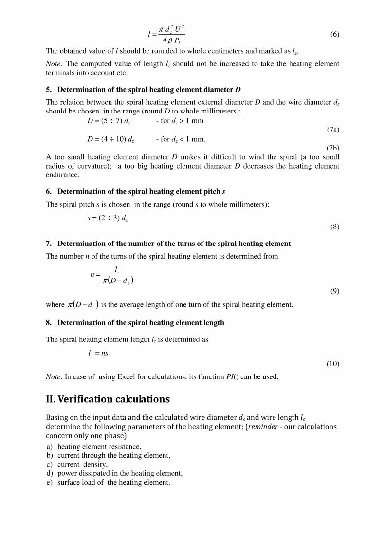
4. Determination of the wire length
After comparing (1) with (2) and replacing d with dz the wire length l can be calculated
1
22
z
P4
Udl
ρ
π= (6)
The obtained value of l should be rounded to whole centimeters and marked as lz.
Note: The computed value of length lz should not be increased to take the heating element
terminals into account etc.
5. Determination of the spiral heating element diameter D
The relation between the spiral heating element external diameter D and the wire diameter dz
should be chosen in the range (round D to whole millimeters):
D = (5 ÷ 7) dz - for dz > 1 mm
(7a)
D = (4 ÷ 10) dz - for dz < 1 mm.
(7b)
A too small heating element diameter D makes it difficult to wind the spiral (a too small
radius of curvature); a too big heating element diameter D decreases the heating element
endurance.
6. Determination of the spiral heating element pitch s
The spiral pitch s is chosen in the range (round s to whole millimeters):
s = (2 ÷ 3) dz
(8)
7. Determination of the number of the turns of the spiral heating element
The number n of the turns of the spiral heating element is determined from
( )
z
z
dD
ln
−=
π
(9)
where ( )zdD −π is the average length of one turn of the spiral heating element.
8. Determination of the spiral heating element length
The spiral heating element length ls is determined as
nsls =
(10)
Note: In case of using Excel for calculations, its function PI() can be used.
II. Verification calculations
Basing on the input data and the calculated wire diameter dz and wire length lz
determine the following parameters of the heating element: (reminder - our calculations
concern only one phase):
a) heating element resistance,
b) current through the heating element,
c) current density,
d) power dissipated in the heating element,
e) surface load of the heating element.

Note: In the verification calculations above use dz and lz (obtained after rounding) – not d and
l, calculated directly from (5) and (6).
III. Report contents 1. Place a summary of the following quantities obtained during execution of p. I quoting also
the formula used:
a) resistance furnace assumed power P, kW,
b) power P1 of a single phase, kW,
c) calculated heating element resistance, equal to the wire resistance, Ω,
d) surface load of the heating element assumed,
e) wire diameter d calculated from (5), mm,
f) wire diameter dz chosen from the catalogue (Fig.2), mm,
g) wire length l calculated from (6), m,
h) wire length lz rounded to whole centimeters, m,
i) spiral heating element external diameter D, mm,
j) spiral heating element pitch s, mm,
k) number of the turns of the spiral heating element,
l) spiral heating element length ls, m.
2. Place the results of the verification calculations from p. II. Make sure that the surface load
calculated here is within the permissible area (Fig.3).
3. Place a summary of the following quantities assumed or calculated in p.1 of the report and
verified in p.2 of the report adding also relative errors:
a) heating element resistance,
b) heating element power,
c) heating element surface load.
Make sure that the relative errors are small.
IV. Bibliography
[1] Hering M.: Podstawy elektrotermii cz.I, WNT, Warszawa 1992 (in Polish).
[2] KANTHAL datasheet:
http://www.kanthal.com/Global/Downloads/Materials%20in%20wire%20and%20strip%20for
m/Resistance%20heating%20wire%20and%20strip/S-KA026-B-ENG-2012-01.pdf
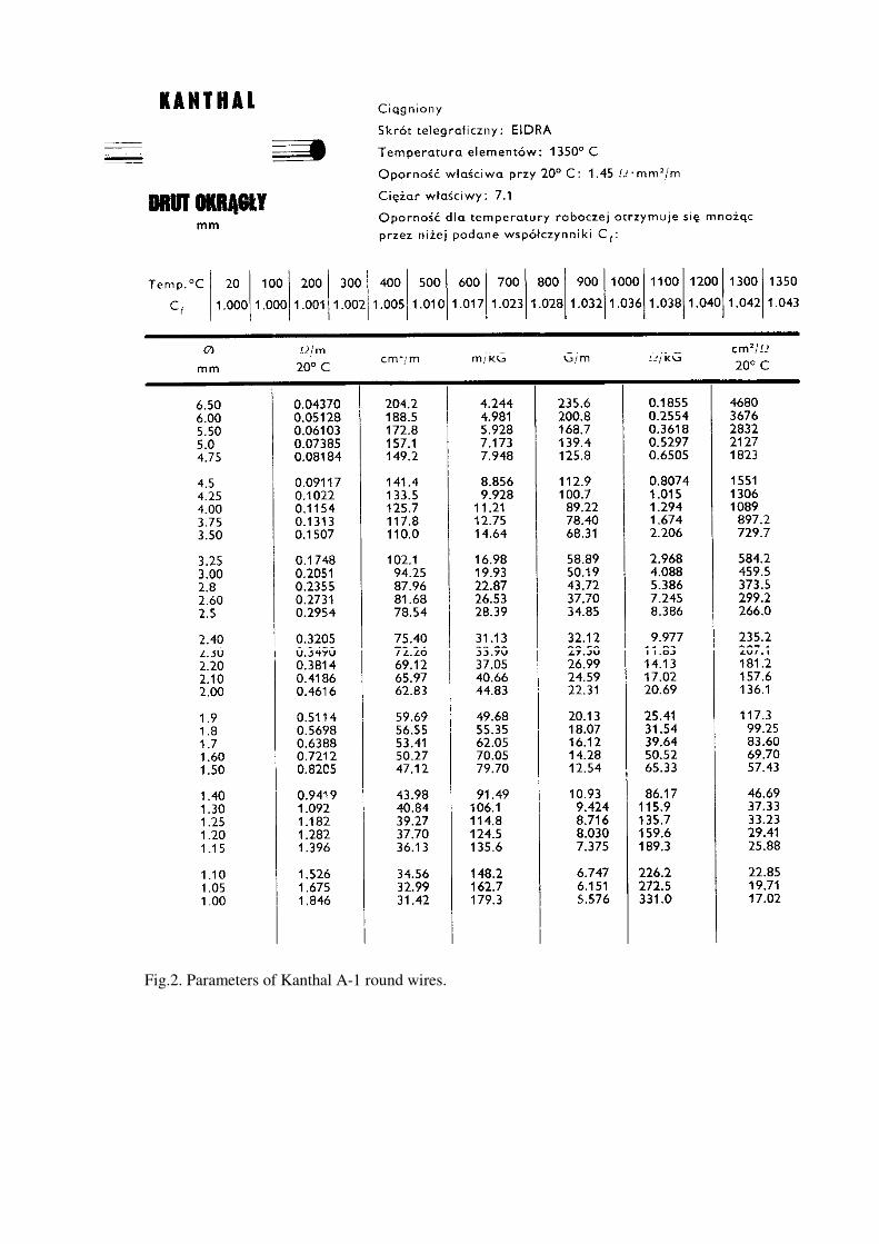
Fig.2. Parameters of Kanthal A-1 round wires.

Fig.3. Surface load of round wires used in industry furnaces. Consider Kanthal A-1.