i inch-pound superseding milc-21723a(os) military
TRANSCRIPT
I INCH-POUND I
MILC-21723B8 Februarv 1994SUPERSEDINGMILC-21723A(OS)27 September 1971
MILITARY SPECIFICATION
COMPOWI’ION CH-6
lhis spec&icarionis approved for use by all Depanments and Agencies of the Department of D#ense.
1. SCOPE
1.1 Scope. TM specification establishes the requirements for an explosive designated asComposition CH-6.
1.2 Classification. Explosive Composition CH-6 shall have the following classes:
class 1- Composition CH-6 which is subjected to calibration testing with a lowersensitivity level of 3.5 decibang (DBg) and an upper sensitivity level of 6.0 DBg.
Cblss 2- Composition CH-6 which has the same fixed lower sensitivity level (3.5 DBg)as the Class 1 material when subjected to calibration testing but a differentvalue for the upper sensitivity. ‘lTds vaiue shalI be specified at the time ofprocurement.
2. APPLICABLE DKWMEWS
2.1 Gmrmnent documents.
2.1.1 Sp5fications and standards. The following specifications and standards forma partof this document to the extent specified herein. Unless otherwise specified, the issues of thesedocuments are those listed in the issue of the Department of Defense Index of Specifications andStandards (DODISS) and supplement thereto, cited in the solicitation (see 6.2).
Benefkial comments (recommendations,additions, deletions)and any pertinentdata which may be of usein improvingthis documentshouldbe addressedto the Commander,IndianHead DivKlon,Naval SurfaceWarfare Center, 101 Strauss Avenue, Indian Head, MD 20640-5000, by using the StandardizationD-ent ImprovementProposal (DDForm 1426) appearing at the end of this documentor by letter.
AMSC NIA ~ 1376DISTRIBUTION STATEMENT A. Approved for public release; distribution is unlimited.
Downloaded from http://www.everyspec.com
SPECIFICATIONS
FEDERAL
RR-S-366
MILITARY
MIL-G155
MIL-R-398
MIL-C-51511
STANDARDS
FEDERAL
FED-STD-313
MILC-21723B
Sieves; Standard, Testing
Graphite
RDx
Calcium Chloride, Technical
Material Safety Data, Transportation Data and Disposalfor Hazardous Materials Furnished to GovernmentActivities
MILITARY
MHA3TD-105 Sampling Procedures and Tables for Inspection byAttributes
MIL-STD-129 Marking for Shipment and Storage
(Unless otherwise indicated, copies of federal and military specifications and standards areavailable from the Standardization Documents Order Desk, Building 4D, 700 Robbins Avenue,Philadelphia, PA 19111-5094.)
2.12 Other Government documents, drawings, and publications. The following otherGovernment documents, drawings, and publications form a part of this document to the extentspecified herein. Unless otherwise specified, the issues are those cited in the solicitation (see6.2).
DRAWINGS
NAVAL SEA SYSTEMS COMMAND (CAGE Code 10001)
LD 70518 Impact MachineLD 479544 Powder Mobility Gage for CH-6 ExplosiveLD 479593 Initiation Sensitivity Test Fixture for CH-6 Explosive
2
Downloaded from http://www.everyspec.com
MILC-21723B
LD 549486
LD 162071416207132426912242691324269142426915242691624269172426918
Explosive Properties, I&t of Drawings, Assemblim, Parts,Specifications, Etc.Alternate Dent BlockSample PelletExplosives Properties AssemblyDonor AssemblyAcceptor AssemblyAcceptor BodyDent BlockAttenuatorHolder
(Application for copies should be addressed to the Commanding Officer, Naval OrdnanceStation, Crane Division, Naval Surface Warfare Center, Attention: Code 802, Louisville, KY40214-5001.)
U.S. ARMY ARMAMENT RESEARCH, DEVELOPMENT AND ENGINEERINGCENTER (ARDEC)
7548644 Box, Packing for High Explosives, Assembly, Details,Packing and Marking
7548645 Carton, Packing, Reusable, Collapsible for High Explosives
(Application for copies should be addressed to the Commander, U.S. Army InformationSystems Command, Attn: ASQNC-API?-OPT, Picatinny Arsenal, NJ 07806-5000.)
CODE OF FEDERAL REGULATIONS
46 CFR 100-199 Transportation
(Application for copies should be addressed to the Superintendent of Documents, U.S.Government Ih+nting Office, Washington, DC 20402.)
22 NmKkmrmnent publications. The following document forms a part of this documentto the extent specified herein. Unless otherwise specified, the issue of the document which isDOD adopted is that listed in the issue of the DODISS cited in the solicitation. Unless otherwisespecified, the issue of the document not listed in the DODISS is the issue of the document atedin the solicitation (see 6.2).
EXXON CHEMICAL CORPORATION
Vktanex LM-MH Polyisobutylene
(Application for copies should be addressed to the Exxon Chemical Corporation, IP.O. Box3272, Houston, TX 77253.)
3
Downloaded from http://www.everyspec.com
MIIX-21723B
(Non-Government standards and other publications are normally available from theorganizations that prepare or distribute the documents. These documents also may be availablein or through libraries or other informational services.)
2.3 Order of precedence. In the event of a conflict between the text of this document andthe references cited herein, the text of this document takes precedence. Nothing in thisdocument, however, supersedes applicable laws and regulations unless a specific exemption hasbeen obtained.
3.1 Description. Composition CH-6 is a homogeneous explosive mixture of RDX, graphite,calcium stearate and polyisobutylene. This mixture when compared to tetryl, withstands highertemperature before cook off, has higher output, yet matches the sensitivity of tetryl. .~e flOWcharacteristics of this mixture permit the manufacture of Composition CH-6 pellets of a densityof at least 1.61 grams per cubic centimeter (@c) and various diameters that will hold togetherunder ordinary handling conditions.
3.2 Mrst article. Unless otherwise specified in the contract or purchase order (see 6.2), afirst article sample (see 6.3) shall be tested as specified in 4.4.
33 MMaials. The materials used in the manufacture of the Composition CH-6 explosivepurchased under this specification shall conform to their respective specifications prior to theirusage and shall be of the type, grade, and/or class as specified in 33.1 through 3.3.3 (see 6.6).
33.1 RDX expIosiva The RDX explosive shall meet the requirements of MIL-R-398, TypeII, class 1.
332 Graphite. The graphite material shall meet the requirements of MIL-G155, Grade I.
333 Polyisobutykzw The polyisobutylene shall meet the requirements of PolyisobutyleneVistanex LM-MH as manufactured by the I&xon Chemical Corporation, P.O. Box 3272,Houston, TX 77253, or equivalent.
3.4 Chemical and physical properties requirements. Unless otherwise specified in thecontract or purchase order (see 6.2), Composition CH-6, Class 1 shall conform to therequirements specified in Table I when tested in accordance with the applicable methods.Composition CH-6, Class 2 shall conform to the requirements of Table I, with the functioningcharacteristics as sp~fied in the contract or purchase order (see 6.2).
3s Wo - ““p. The manufacturer shall use procedures and controls which will ensurethat the Composition CH-6 produced does not contain foreign material such as dirt, rust, paint,metal cldps or other foreign substances which may cause a detrimental effect on the safety andreliability of the explosive. The workmanship exhibited in the first article sample shall beevaluated to determine acceptability. The approved standards of workmanship shall therebybecome the minimum workmanship standards for the production of the explosive.
4
Downloaded from http://www.everyspec.com
MIL-C-21723B
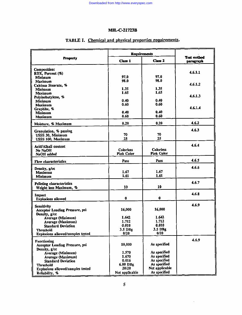
TABLE I. Chemical and Dhwicd DroDerties requirements.
Re@remdaTestmethod
Classl class2 w-mph
Composition:RDX, Percent (%) 4.6.1.1
Mlnhnum 97.0 97.0Maximum 98.0 98.0CaklumStearate,% 4.6.1.2Miniium 1.35 1.35Maxiium 1.65 1.65Polyisobutylene,% 4.6.1.3
Miniium 0.40 0.40Maximum 0.60 0.60Graphii,% 4.6.1.4Minimum 0.40 0.40Maximum 0.60 0.60
Moisture, % Maxiium 0.20 0.20 4.6.2
GranuMion,%passing 4.6.3USSS 30, Miniium 70 70USSS 100, Maxiium 25 25
AcWAlkali content 4.6.4
No NaOH Colorless ColorlessNaOH added Pmk Color Pmk Color
Flow characteristics Pass Pass 4.6.S
Density, gkc 4.6.6Maxiium 1.67 1.67Miniium 1.61 1.61
Pell&ing characteristics 4.6.7WeightlossMaxiium, % 10 10
Impact 4.6.8
Explosions allowed o 0
Sensitivity 4.6.9Acceptor Loadiig Pressure, psi 16,000 16,000Densii, @cc
Average (Minimum) 1.642 1.642Average (Maximum) 1.712 1.712Standard Deviation 0.010 0.010
Threshold 3.5 DBg 3.5 DBgExplosions aUowed/samples tested 0120 0/20
Functioning 4.6.9
Acceptor Loading Pressure, psi 10,000 As specifiedDens”@, gkc
Average (M.inhnum) 1.570 As Spfx”fied
Average (Maximum) 1.670 As Spec”fiedStandardDeviation 0.016 Asspecified
Threshold 6.00 DBg As SpecifidExplosions allowed/samples tested 20/20 Not applicable
Reliability, % Not applicable As specified
5
Downloaded from http://www.everyspec.com
MILC-21723B
3.6 Safety.
3.6.1 Toxic products and formulations. The material shall have no adverse effect on thehealth of personnel when used for its intended purpose. Questions pertinent to this effect shallbe referred by the contracting activity to the appropriate departmental medical service who willact as an advisor to the contracting agency (see 4.1.2).
3.62 Material safety data sheets. The contractor shall prepare and submit Material SafetyData Sheets in accordance with FED-STD-313 as specified in the contract (see 6.7).
4. QUAIXI’Y ASSURANCE PROVISIONS
4.1 Rqmnsihility for “wpection. Unless otherwise specified in the contract or purchaseorder (see 6.2), the contractor is responsible for the performance of all inspection requirements(examinations and tests) as specified herein. Except as otherwise specified in the contract orpurchase order, the contractor may use his own or any other facilities suitable for theperformance of the inspection requirements specified herein, unless disapproved by theGovernment. The Government reserves the right to perform any of the inspections set forth inthk specification where such inspections are deemed necessary to ensure supplies and servicesconform to prescribed requirements.
4.1.1 Responsibility for compliance. All materials shall meet all the requirements of sections3 and 5. The inspections set forth in this specification shall become a part of the contractor’soverall inspection system or quality program. The absence of any inspection requirement in thespecification shall not relieve the contractor of the responsibility of ensuring that all materialssubmitted to the Government for acceptance comply with all requirements of the contract.Sampling inspection, as part of manufacturing operations, is an acceptable practice to ascertainconformance to requirements. However, this does not authorize submission of known defectivematerial, either indkated or actual, nor does it commit the Government to accept defectivematerial.
4.1.2 Toxicological product formulations. The contractor shall have the toxicologicalproduct formulations and associated information for review by the contracting activity toevaluate the safety of the material for the proposed use (see 3.6.2).
42 Classification of “mpections. The inspection requirements specified herein are classifiedas follows:
a. Fkst article inspection (see 4.4).
b. Quality conformance inspection (see 4. S).
43 Test equipments, fktures, and conditions. The test equipments, fixtures, and conditionsof 4.3.1 and 4.3.2 are required to perform the tests of 4.6:
6
Downloaded from http://www.everyspec.com
MIIX-21723B
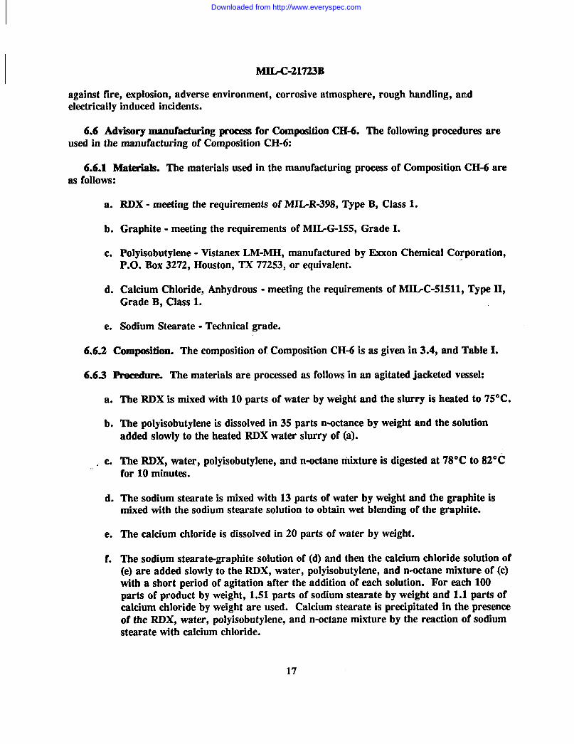
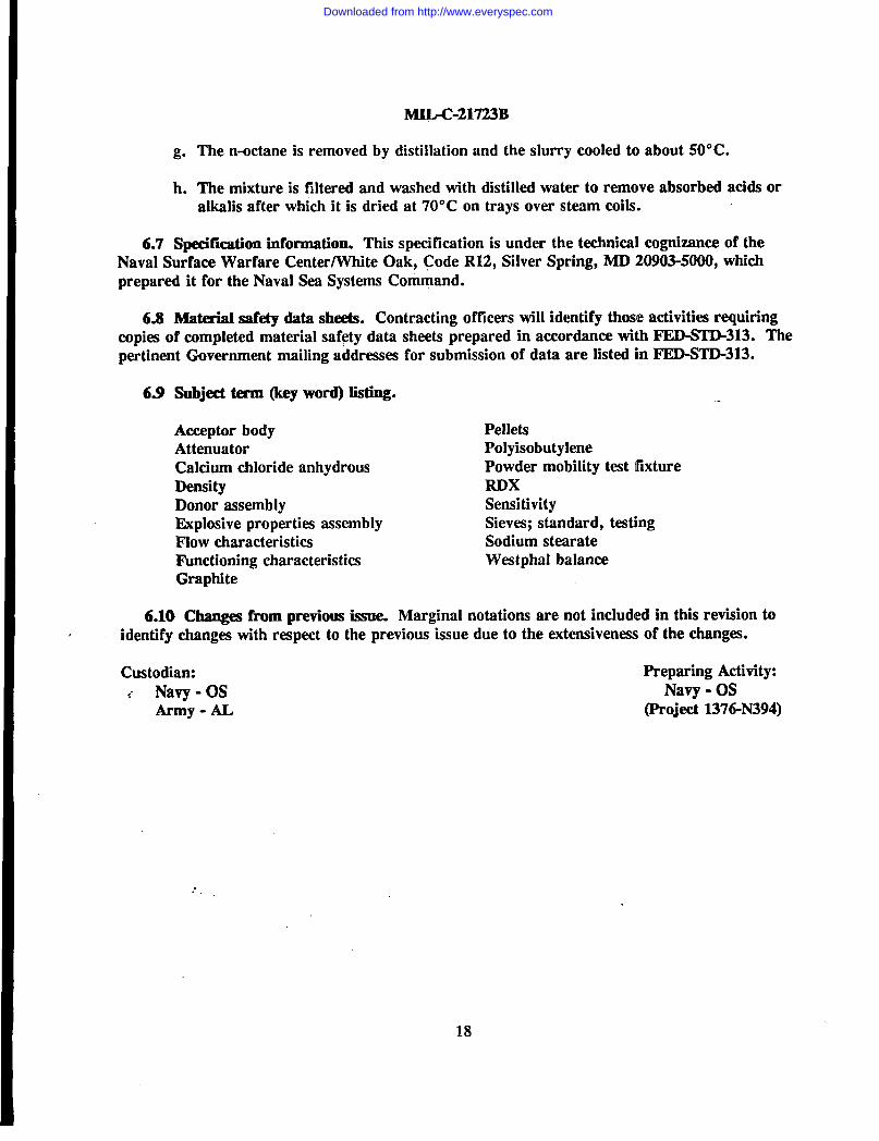
423.1 Test equipments and tktures. The following test equipments and fixtures are requiredto perform the tests specified in 4.6:
a.
b.
c.
d.
e.
f.
g“
h.
i.
j.
k.
Standard testing sieves; top plate; bottom plate meeting the requirements of RR-S-366
Mechanical Sieve Shaking Machhe
Powder Mobility Test Fixture for CH-6 Explosive - BUORD LD 479544
Westphal Balance for Density Determinations
Impact Machine - BUIORDLD 70518
Explosives Properties Assembly - Drawing 2426912
Donor Assembly - DWG 2426913 (Hgure 3)
Small Scale Gap Test (SSGT) for Testing Donors (Figure 4)
Acceptor Body - (Figure 5)
Small Scale Gap Test Configuration - (Mgure 6)
Attenuator - See table for Attenuator in Figure 6.
432 Test GmIitions. Unless otherwise specified (see 6.2), the Composition CH-6 shall besubjected to acceptance tests under the following conditions:
a. Temperature: Room ambient 65 to 95 degxws Fahrenheit (“F) (18.3 to 35.0 degreesCelsius (“C))
b. Altitudw Normal ground
c. Vibration: None
d. Humidity: Room ambient to 95 percent relative maximum.
4.4 Mmt article inspection. Fkst article inspection shall consist of all the tests specified in4.6. The first article shall be the first production by the contractor, using the same productionprocesses, procedures, and equipment to be used in fulfilling the contract. The first articlesample shall be of sufficient quantity to perform the specified tests. Failure to meet the specifiedrequirements shall be cause for rejection of the first article.
4.5 Quality conformance imption. The quality conformance inspection shall consist of thetests specified in 4.6. Inspections and test procedures shall be submitted for Governmentapproval prior to commencement of production. Inspection shall be performed by the
7
Downloaded from http://www.everyspec.com
MIL-C-21723B
manufacturer unless otherwise specified in the contract or purchase order (see 6.2). Anydeviation from the specified technical requirements shall result in rejection of the batch.
4.5.1 Batch. For the purpose of sampling, a batch of Composition CH-6 shall be limited inweight to 7000 pounds maximum. A batch shall consist of material produced in a singlemanufacturing run, with no more than one lot of each ingredient material with no change informulation or process to make the final product homogeneous. Physical blending of more thanone batch wet or dry, shall not be permitted. A batch may be formed by reworking one ormore batches by the slurry coating process in a crystallization still.
4.52 Sampling. Sampling shall be performed on each batch before packing by takingapproximately equal quantities of material from each nutche (storage container) and blendinginto a composite sample of approximately 2 pounds, half of which shall be used for the tests of4.6. The remaining 1 pound sample shall be retained for possible check analysis. A batch maybe divided into more than 1 lot, and the tests performed on the batch may be reported for eachof the lots.
4,5.2.1 Sample pelkts. Composition CH-6 pellets used in the test of 4.6.6 shall be preparedin accordance with Drawing 1620713 wldch is part of LD 479593 using the CH-6 from compositesample in 4.5.2. Fabricate 20 pellets each as a single lot from which the required test pelletsshall be drawn in a statistically random fashion using a table of random numbers or equivalentprocedure.
4.S.2.2 Marking of sample containers. Each sample container shall be marked to show thename of the material, manufacturer, plant, lot, batch number, and the date of manufacture.
4.6 Test procedures.
4.6.1 Analysis of Composition CH-6. All analyses utilizing loose bulk material shall becarried out in duplicate on each sample. Rifflhg of sample is permitted. This provision is notapplicable to the tests whkh utilize pellets. Failure of the composite sample to meet thecomposition requirements of Table I shall cause rejection of the lot from whkh the sample istaken.
4.6.1.1 RDX. Transfer an accurately weighed portion of approximately 10.0 grams (g) ofthe composite sample of Composition CH-6 from 4.5.2 into a tared medium porosity, sintered-glass crucible. Place the crucible containing the sample on a suction flask and fill with 25milliliters (mL) of hot acetone (55 + 5° C) and apply vacuum. Repeat thk procedure 7additional times (total acetone equals 200 mL). Dry the crucible and contents in an oven at 100* 5°C for 40 to 50 minutes. Cool in a desiccator and weigh. All of the above operations, withthe exception of the weighing and drying, must be conducted in a hood. IMor to discarding theacetone-RDX solution, it should be mixed with a large volume of water and then filtered toremove the RDX from the solution. The waste RDX should be stored under water until readyfor disposal by safe destructive chemical or burning procedures. Calculate the loss in weight asRDX in the sample on a dry basis as follows:
8
Downloaded from http://www.everyspec.com
Percent RDX (%) = l*[#__-$M]
where A =B =M=w=
weight of crucible and sampleweight of crucible and sample after extraction with hot acetonepercent moisture expressed as a decimalweight of sample
4.6.1.2 Calcium stearate. Place the crucible and residue from 4.6.1.1 on the filter flask.Add 12 mL of hot glacial acetic acid (110 * 5°C) to the crucible and allow to stand for 2minutes, then apply vacuum. Repeat thk procedure twice with the same volume of acetic acid,then once with a filling of the crucible (total volume of glacial acetic acid equaIs 60 mL).Finally, wash the residue with 25 mL of acetone and discard the acetic acid-acetone solution.Dry the cruable and residue in an oven at 100 * 5°C for 40 minutes. Cool in a desiccator andweigh. All of the above operations, with the exception of weighhg and drying, must beconducted in a hood.
Percent Calcium Skwrote (%) = 1$(~~
where: B = weight of crucible and sample after extraction with hot acetonec = weight of crucible and sample after extraction with glacial acetic acid and acetoneM= percent moisture expressed as a decimalw= weight of sample
4.6.1S Polyisobutylene Warm the crucible and residue from 4.6.1.2 by placing it in anoven at 100 * 5°C for 5 minutes, then place it on the filter flask. Add 25 mL of hot toluene(105 * 5°(2) to the crucible and let stand for 2 minutes and apply vacuum. Repeat thisprocedure 7 more times (total volume of toluene equals 200 mL). Finally, wash the residue with25 mL of acetone. Dkard the toluene-acetone solution. Dry the crucible and residue in anoven at 100 * 5“c for 40 to sO minutes. COOIin a desimtor ad weigh. Ml of the aboveoperations, with the exception of weighing and drying, must be conducted in a hood.
Percent Pofyisobutyfene (%) =1OO(C-D)W(l-a’f)
where: C = weight of crucible and sample after extraction with glaaal acetic acid and acetoneD = weight of crucible and sample after extraction with toluene and acetoneM= percent moisture expressed as a decimalw= weight of sample
4.6.1.4 Graphite Calculate the weight of the residue remaining in crucible in 4.6.1.3 aspercent graphite in the sample on a dry basis as follows.
..
9’
Downloaded from http://www.everyspec.com
MHIX-21723B
Percent Graphite (%) = lf~&B
where: D =E=w=M=
weight of crucib!e and sample after extraction with toluene and acetoneweight of crucibleweight of samplepercent moisture expressed as a decimal
4.6.2 Moisture. Transfer an accurately weighed portion of approximately 10.0 g of thecomposite sample of Composition CH-6 from 4.5.2 to a tared weighing bottle with an outsideground cap. Place the bottle and contents with cap removed in an oven at 100 * 5°C for 40 to50 minutes; cool in a desiccator, stopper and reweigh. Calculate the loss in weight of the bottleand contents as percent moisture in the sample. Failure of the composite sample to meet themoisture requirements of Table I shall cause rejection of the batch from whkh the sample istaken.
4.6S Granulation. Place a weighed portion of approximately 15 g of the composite sampleof Composition CH-6 from 4.5.2 on the specified standard testing sieves of 4S.1 whkh isprovided with a bottom pan. Cover and shake for 15 minutes in a mechanical shaker geared toproduce 300 t 15 gyrations and 150 * 10 taps of the striker per minute. Weigh the portionretained by the sieve and calculate on a percentage basis as required. Failure of the compositesample to meet the granulation requirements of Table I shall cause rejection of the batch fromwhich the sample is taken.
4.6.4 Acid and alkali content test. Place 10.0 + 0.1 g of Composition CH-6 taken from thecomposite sample of 4.5.2 in a 100-mL beaker. Add 50 mL of freshly boiled and distilled water,agitate the slurry for approximately 5 minutes at ambient temperature and filter. Add 2 dropsof 1% phenolphthalein solution to the filtrate and examine the filtrate for color change. Thefiltrate shall remain colorless and show no evidence of pink color. Following this add 0.05 ml of0.1 normal (N) NaOH solution. Failure of the filtrate from the Composition CH-6 sample toremain colorless after addition of the phenolphthalein indkator solution or to change fromcolorless to a pink color on addition of the O.lN NaOH solution shall cause rejection of the batchof Composition CH-6 from whkh the sample is taken.
4.6.5 Fk)W chamdms ● th. Fill the Powder Mobility Gage shown on Drawing 1518531,which is part of LD 479544, with Composition CH-6 from the composite sample of 4.5.2. Careshall be exercised in filling the gage to prevent packing of the explosive. After completion of thefilling operation, release the door and allow the Composition CH-6 to flow from the gage. Theoccurrence of a sample of the Composition CH-6 which does not flow through the gage orificeon release of the door shall cause rejection of the batch from which the sample is taken.
4.6.6 De&ty. Select 15 pellets from the lot of sample pellets in accordance with 4.5.2.1.Calculate the average density of the 15 pellet sample. The densities of the pellets shall bemeasured by the procedures of either 4.6.6.1 or 4.6.6.2. Failure of the pellets to meet the
Downloaded from http://www.everyspec.com
MILC-21723B
average density requirements of Table I shall cause rejection of the lot from which the samplepellets were taken.
4.6.6.1 Displacement method. Coat the pellets with a thin film of protective water proofingsuch as clear acrylic lacquer in an aerosol spray. A weight increase in excess of 0.025 g willmake the pellet unacceptable for the test. A small amount of wetting agent shall be added to thewater to aid in removal of air from the pellet surface. Density shall be determined by the water-displacement/water-loss method using the Westphal specific gravity balance.
4.6.62 Dry measurcment mctlmd. For each pellet, measure (to the nearest thousandth) thefollowing:
a. The diameter of the pellet in 2 locations, 90° apart. Calculate the diameter (D) ofthe pellet as follows:
where: D1
b.
D1 •+D2D=
2
and Dz = Diameter of the pellet in inches at locations 1 and 2.
The height of the pellet in 4 places around the edge, each 90° apart. Calculate theheight (H) of the pellet as follows:
~l+H.. +H3+H4H=
4
where: H,, Hz, H~, & ~ = Height of the pellet in inches at each of the 4 places measured.
Each pellet shaI1 also be weighed to an accuracy of* 0.002 g.above information, the density of the pellet is calculated as:
Density (g/cc) = ‘“W’(WD2(H)
4.6.7 PelIeting chmwkns “ tics. Select 5 pellets from the lot
Call this weight W. With the
of sample pellets prepared inaccordance with 4.5.2.1. Weigh the 5 pellets and place them in a cylindrical metal can, 5 * 1inches (12.7 + 2.5 centimeters (cm)) in diameter by 9 i 1 inches (22.86 * 2.5 cm) h~gh. Thecan containing the pellets shall be rotated end over end for 10 minutes at 21 revolutions perminute. After completion of the tumbling, the pellets shall be removed from the can, wiped freeof dust and reweighed. The weight loss shall be expressed as percent of the total original weightof the 5 pellets. Failure of the 5 pellets to meet the pelleting characteristics requirement ofTable I shall cause rejection of the lot from which the sample pellets are taken.
4.6,S Impact. A 35-milligram (mg) sample of Composition CH-6 shall be taken from thecomposite sample of 4.5.2 and shall be dried prior to impact testing. Drying shall be done inthe same manner as the sample for functioning test of 4.6.9. Impact machine (see IX) 70518)
11
Downloaded from http://www.everyspec.com
MIL-C-21723B
shall be used for impact testing. Place the 35-mg sample on the rough side of a piece of No. 05sandpaper which is supported on the steel anvil shown on figure 1. Place the hardened steelstriker shown on figure 2 over the sample of explosive resting on the sandpaper and anvil. Dropa 2.5-kilogram (kg) steel weight from the height determined by the procedure of 4.6.8.1 in africtionless guided drop so that it impacts the striker centrally. Repeat this test 15 times using anew sample of Composition CH-6 and a new sheet of sandpaper for each test. The burning orexplosion of the Composition CH-6 in one or more of the test drops shall cause rejection of thelot of Composition CH-6 from which the sample is taken.
4.62.1 Ddamma“ tion of “npact testing height. Employing the same test equipment and testprocedure as described in 4.6.8, with the exception that Government furnished tetryl shall besubstituted for the Composition CH-6, determine the maximum height, within 1 inch from whichthe 2.5-kg weight can be dropped without explosion of the tetryl. Ttds maximum no-fire heightshall be the maximum height at which 15 successive drops can be made using a new sample ofthe tetryl each time without the occurrence of an explosion. Nhety percent of this maximummwfire height, to the nearest % inch, shall be the testing height for the Composition CH-6 in4.6.8.
4.69 SenAt.ivity and functioning tests. A representative sample of explosive CompositionCH-6 from 4.5.2 shall be dried a minimum of 4 hours at 50”C under vacuum of 28.5 inchmercury just prior to loading (see LD 549486). Moisture content at time of loading must notexceed 0.2%. The Composition CH-6 material shall be loaded according to the procedures ofparagraphs 4.6.9.1 and 4.6.9.2.
4.6.9.1 Loading and calibration of donor assemblies. A minimum batch of 50 donors forclass 1 and 60 donors for class 2 material shall be prepared in accordance with NAVORDDrawing 2426913 (see figure 3). Five sample donors shall be selected from each batch inaccordance with MHATD-105, Inspection Level IL These donors shall be assembled in the testarrangement (see figure 4) and fired against the dent block (NAVORD Drawing 2426916) oralternate dent block (NAVORD LD 1620714) by initiating the detonator @upont No. 6 orequivalent blasting cap) using the recommended manufacturer’s power requirements forinitiation. To be acceptable for use in the sensitivity test, the average depth of dent produced inthe block by the donors must be between 60 and 69 roils and the standard deviation must notexceed 5.0 roils. Each block shall be used only once. The measurement of the indentation depthshall be made in accordance with 4.6.9.4.
4.69.2 Prqwation of acceptor specimen for sensitivity/functioning test. The explosiveComposition CH-6 shall be loaded in 8 equal weight increments. The first trial loading shall bewith 8 equal increment weights, given in Tables H and III. The acceptor body (NAVORDDrawing 2426915) shall be weighed before and after loading (see figure 5). If all 8 incrementsfit in the acceptor body with room to spare, adjust the subsequent acceptor by measuring theremaining unloaded column height and increasing equally the weight of each increment to meetthe tolerance shown in NAVORD Drawing 2426914. If all 8 increments do not fit into theacceptor body, adjust the individual increment weight equally (based on the actual weight ofexplosive contained in the body) to meet the tolerances given in NAVORD Drawing 2426914.The acceptors shall have a black mark placed on the fill end and be weighed with a minimum
12
Downloaded from http://www.everyspec.com
MILC-21723B
accuracy of * 5 mg before and after loading. The density of each individual acceptor shall bedetermined in terms of grams/cubic centimeters (@cc) and reported to three decimal places.The average density shall be in accordance with those shown in Tables II and III, and thecalculated standard deviation of the densities shall be no greater than 0.010 @cc for thesensitivityy test hardware, and no greater than 0.016 gkc for the functioning test hardware.Only these acceptors that meet the density requirement specified will be used in the sensitivityand functioning tests of 4.6.9.3.
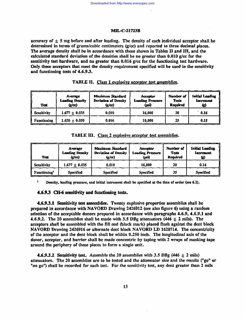
TABLE IL Class 1 ext)losive acceDtor test assemblies.
Avemge Maximumstandard Nombrrof hlit5alLlIdingLoadingway kviatboof Iklsii LoadiogPre?iaure J t
Teit (g/Cc) @la) @o s 49
sensitivity 1.677+ 0.035 0.010 16,000 20 0.16
Function”~ 1.620* 0.050 0.016 10,000 2s 0.1s
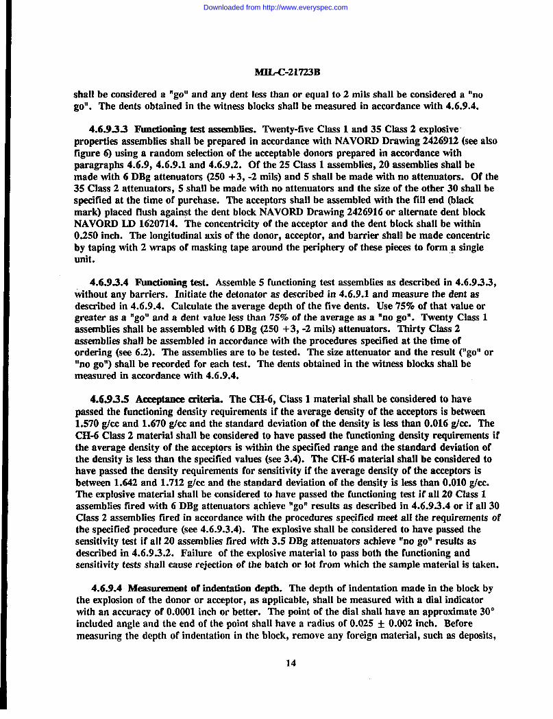
TABLE III. Class 2 exrhsive acce@or test assemblies.
Average maximumstandard Numberof InitinlLuadblgLoading Density Deviatbnof Jle@i L4mding Ressore T- Inrlwlnealt
Test @a) (g/Cc) G@ Rrqoired @
Sensbivity I 1.677 * 0.035 I 0.010 ! 16,000 I 20 I 0.16
Functioningi I specified I Specxed I Spdkd I 35 I Specifbd
1 Densii, badii pressure, and inkial increment shall be specitied at the time of order (see 6.2).
4.693 (3I4 smsitivityand fimctioning trots.
4.693.1 Sensitivity test assemblies. Twenty explosive properties assemblies shall beprepared in accordance with NAVORD Drawing 2426912 (see also figure 6) using a randomselection of the acceptable donors prepared in accordance with paragraphs 4.6.9, 4.6.9.1 and4.6.92. The 20 assemblies shall be made with 3.5 DBg attenuators (446 * 2 mik). Theacceptors shall be assembled with the fill end (black mark) placed flush against the dent blockNAVORD Drawing 2426916 or alternate dent block NAVORD LD 1620714. The concentricityof the acceptor and the dent block shall be within 0.250 inch. The longitudinal axis of thedonor, acceptor, and barrier shall be made concentric by taping with 2 wraps of masking tapearound the periphery of these pieces to form a single unit.
4.69.X2 =tivity test. Assemble the 20 assemblies with 3.5 DBg (446 * 2 mi~)attenuators. The 20 assemblies are to be tested and the attenuator size and the results (“go” or“no go”) shal! be recorded for each test. For the sensitivity test, any dent greater than 2 roils
13
Downloaded from http://www.everyspec.com
MILC-21723B
shall be considered a “go” and any dent less than or equal to 2 roils shall be considered a “nogo”. The dents obtained in the witness blocks shall be measured in accordance with 4.6.9.4.
4.6.933 Functioning test assemblies. Twenty-five Class 1 and 35 Class 2 explosiveproperties assemblies shall be prepared in accordance with NAVORD Drawing 2426912 (see alsofigure 6) using a random selection of the acceptable donors prepared in accordance withparagraphs 4.6.9, 4.6.9.1 and 4.6.9.2. Of the 25 Class 1 assemblies, 20 assemblies shall bemade with 6 DBg attenuators (250 +3, -2 roils) and 5 shall be made with no attenuators. Of the35 Class 2 attenuators, 5 shall be made with no attenuators and the size of the other 30 shall bespecified at the time of purchase. The acceptors shall be assembled with thetillend(blackmark) placed flush against the dent block NAVORD Drawing 2426916 or alternate dent blockNAVORD LD 1620714. The concentricity of the acceptor and the dent block shall be within0.250 inch. The longitudinal axis of the donor, acceptor, and barrier shall be made concentricby taping with 2 wraps of masking tape around the periphery of these pieces to form a singleunit.
4.6.9.3.4 Ihwtioning test.Assemble 5 functioning test assemblies as described in 4.6.9.3.3,ivithout any barriers. Initiate the detonator as described in 4.6.9.1 and measure the dent asdescribed in 4.6.9.4. Calculate the average depth of the five dents. Use 75% of that value orgreater as a “go” and a dent value less than 75% of the average as a “no go”. Twenty Class 1assemblies shall be assembled with 6 DBg (250 +3, -2 roils) attenuators. Ttdrty Class 2assemblies shall be assembled in accordance with the procedures specified at the time ofordering (see 6.2). The assemblies are to be tested. The size attenuator and the result (“go” or“no go”) shall be recorded for each test. The dents obtained in the witness blocks shall bemeasured in accordance with 4.6.9.4.
4.693S Acceptance criteria. The CH-6, Class 1 material shall be considered tohavepassed the functioning density requirements if the average density of the acceptors is between1.570 g/cc and 1.670 gkc and the standard deviation of the density is less than 0.016 g/cc. TheCH-6 Class 2 material shall be considered to have passed the functioning density requirements ifthe average density of the acceptors is within the specified range and the standard deviation ofthe density is less than the specified values (see 3.4). The CH-6 material shall be considered tohave passed the density requirements for sensitivity if the average density of the acceptors isbetween 1.642 and 1.712 g/cc and the standard deviation of the density is less than 0.010 g/cc.The explosive material shal[ be consider@ to have passed the functioning test if all 20 Class 1assemblies fired with 6 DBg attenuators achieve “go” results as described in 4.6.9S.4 or if all 30Class 2 assemblies fired in accordance with the procedures specified meet all the requirements ofthe specified procedure (see 4.6.9.3.4). The explosive shall be considered to have passed thesensitivity test if all 20 assemblies fired with 3.5 DBg attenuators ackdeve “no go” results asdescribed in 4.6.9.3.2. Failure of the explosive material to pass both the functioning andsensitivity tests shall cause rejection of the batch or lot from whkh the sample material is taken.
4.6.9.4 Measurement of indentation depth. The depth of indentation made in the block bythe explosion of the donor or acceptor, as applicable, shall be measured with a dial indkatorwith an accuracy of 0.0001 inch or better. The point of the dial shall have an approximate 30°included angle and the end of the point shall have a radius of 0.025 * 0.002 inch. Beforemeasuring the depth of indentation in the block, remove any foreign material, such as deposits,
14
Downloaded from http://www.everyspec.com
MWC-21723B
from the dent. Zero the indicator with the point of the probe in the deepest part of the dent.Then take the readings on the surface of the biock at 4 points near the periphery of the block.These points shall be approximately 1.125 inches away from the periphery and 90° apart. Thedent shall be computed as the average of the 4 readings.
4.7 Jnspeclion of packaging. Packaging shall be examined for conformance to section 5.
5. PACKAGING
5.1 Packing. Packing shall be level A or C as specified in the contract or purchase order(S* 6.2).
5.1.1 Level A. The Composition CH-6 shall be packed and marked in accordance withDrawing 7548644.
5.12 Level C. The composition shall be packed and marked in accordance with Drawing7548645.
5.2 Marking. Precautionary and explosive markings shall be in accordance with Code ofFederal Regulation, Title 49, CFR Parts 100 to 199. In addition to any special markingsrequired by the contract or purchase order (see 6.2), unit packages, intermediate packages, andshipping containers shall be marked in accordance with the requirements of MIL-STD-129.
6. N-
@hii section contains information of a general or explanatory nature that may be helpful,but is not mandatory.)
6.1 Intended use. The CH-6 Explosive is to be used in explosive loads and boostem forvarious Navy fuzes.
6.2 AcquisMon requimnents. Acquisition documents must specify the following:
a.
b.
c.
d.
e.
Title, number, and date of this specification.
Issue of DODISS to be cited in the solicitation and, if required, the specific issue ofindividual documents referenced (see 2.1 and 2.2).
If a first article is not required (see 3.1).
Chemical and physical requirements of Composition CH-6, Class 1 if other than asspecified in 3.4.
Functioning characteristics of Composition CH-6, Class 2 (see 3.4 and Table HI).
.1s
Downloaded from http://www.everyspec.com
MILC-21723B
f.
g“
h.
i.
j.
k.
I.
The agency and place where the inspection is to be performed if other than asspecified (see 4.1 and 4.5).
Inspection (test) conditions, if other than as specified (see 4.3.2).
Size of the 30 CH-6 Class 2 explosive properties assemblies for the functioning tests(See 4.6.9.3.3).
&sembly and test procedures for the 30 CH-6 Class 2 functioning test assemblies(See 3.6.9.3.4).
Level of packing required (see 5.1).
Any special marking required (see 5.2).
That the explosive safety precaution requirements of the “Contractors’ SafetyManual for-Ammunition, -Explosiv@ and Related Dangerous Materials”, DOD4145.26M are applicable (see 6.4).
6.3 First article. When a first article inspection is required, the contracting officer shouldprovide specific guidance to offerors whether the item(s) should be a preproduction sample, afirst article sample, a first production item, a sample selected from the first production items, astandard production item from the contractors current inventory (see 3.2), and the number ofiterns to be tested as specified in 4.4. The contracting officer should also include specificinstructions in acquisition documents regarding arrangements for examinations, approval of firstarticle t~t results, and disposition of first articles. Invitations for bids should provide that theGovernment reserves the right to waive the requirement for samples for first article inspectionto those bidders offering a product which has been previously acquired or tested by theGovernment, and that bidders offering such products, who wish to rely on such production ortest, must furnish evidence with the bid that prior Government approval is presentlyappropriate for the pending contract. Bidders should not submit alternate bids unlessspecifically requested to do so in the solicitation.
6.4 Safety precaution. The safety precaution requirements of the “Contractors SafetyManual for Ammunition, Explosives and Related Dangerous Material” (DOD 4145.26M) areapplicable and should be specified in the contract as required by the Federal AcquisitionRegulation (FAR) 23.3.
NOTE When this document is used as part of the description of work to be accomplishedGovernment Activity, the safety precaution requirements of “Ammunition and ExplosivesAshore” (OP5) should be made applicable.
6.5 Hazard notk The Composition CH-6 described herein is a high explosive andconsequently presents a hazard in manufacture, handling, storage, and shipment. The
by a
contractor should recognize this hazard and take appropriate measures to guard and protect
16
Downloaded from http://www.everyspec.com
MJIX-21723B
against fire, explosion, adverse environment, corrosive atmosphere, rough handling, andelectrically induced incidents.
6.6 Advisory manufam process for Composition CH-6. The following procedures areused in the manufacturing of Composition CH-6:
6.6.1 Matmials. The materials used in the manufacturing process of Composition CH-6 areas follows:
a. RDX - meeting the requirements of MIL-R-398, Type B, Class 1.
b. Graphite - meeting the requirements of MILG155, Grade L
c. Polyisobut ylene - Vktanex LM-MH, manufactured by Exxon Chemical Corporation,P.O. Box 3272, Houston, TX 77253, or equivalent.
.
d. Calcium Chloride, Anhydrous - meeting the requirements of MILC-51511, Type II,Grade B, Class 1.
e. Sodium Stearate - Technical grade.
6.6.2 Compmition. The composition of Composition CH-6 is as given in 3.4, and Table I.
6.6.3 Procmlure, The materials are processed as follows in an agitated jacketed vessel:
a. The RDX is mixed with 10 parts of water by weight and the slurry is heated to 75°C.
b. The polyisobutylene is dissolved in 35 parts n-octance by weight and the solutionadded slowly to the heated RDX water slurry of (a).
. c. The RDX, water, polyisobutylene, and n-octane mixture is digested at 7il°C to 82°Cfor 10 minutes.
d. The sodium stearate is mixed with 13 parts of water by weight and the graphite ismixed with the sodium stearate solution to obtain wet blendhg of the graphite.
e. The calcium chloride is dissolved in 20 parts of water by weight.
f. The sodium stearat~graphite solution of (d) and then the calcium chloride solution of(e) are added slowly to the RDX, water, polyisobutylene, and n-octane mixture of (c)with a short period of agitation after the addition of each solution. For each 100parts of product by weight, 1.51 parts of sodium stearate by weight and 1.1 parts ofcalcium chloride by weight are used. Calcium stearate is precipitated in the presenceof the RDX, water, polyisobutylene, and n-octane mixture by the reaction of sodiumstearate with calcium chloride.
17
Downloaded from http://www.everyspec.com
MUX-21723B
g. The n-octane is removed by distillation and the slurry cooled to about 50”C.
h. The mixture is filtered and washed with distilled water to remove absorbed acids oralkalis after which it is dried at 70”C on trays over steam coils.
6.7 Specification “tiormation. This specification is under the technical cognizance of theNaval Surface Warfare Center/White Oak, ~ode R12, Silver Spring, MD 20903-5000, whichprepared it for the Naval Sea Systems Command.
6.8 Mderial safety data sheets. Contracting officers will identify those activities requiringcopies of completed material safety data sheets prepared in accordance with FED-STD-313. Thepertinent Government mailing addresses for submission of data are listed in FED--313.
6.9 Subject term (key word) listing. .
Acceptor body PelletsAttenuator PolyisobutyleneCalcium chloride anhydrous Powder mobility test fixtureDensity RDxDonor assembly SensitivityExplosive properties assembly Sieves; standard, testingFlow characteristics Sodium stearateFunctioning characteristics Westphal balanceGraphite
6.10 Changes from previous issue. Marginal notations are not included in this revision toidentify changes with respect to the previous issue due to the extensiveness of the changes.
Custodian: Preparing Activity:,- Navy -OS Navy - OS
Army - AL (Project 1376-N394)
Downloaded from http://www.everyspec.com
lkfILC-21723B
~I~
o
i~I
------ .. .. .. .. .. .. . . .. .. . --------I
i!Iii
r--l
Nom RJi8hanm--- I
FIGURE 1.Anvil.
19
Downloaded from http://www.everyspec.com
MIIX-21723B
4 350 * .010klchea-!
O------------------.-.-----------~ 2.718 * .010 inches.7a
+I
— -----
FIGURE 2. Striker.
20
Downloaded from http://www.everyspec.com
MILC-21723B
t-’”m’hti -i
Bachhcrcmedtobelmfkdwith \RDxataplwsum oflo,oooi charge to be flush too.oo5
SOOPSL Moistumamtentof inchinside fac8uflxldy.
explosive atthneofloadingm llstnot eamxl 02% (see NAVSEA-2426913 far loadingCktaik).
FIGURE 3. Donor assemblies for smaIl scale ~a~ test.
(fiuuldblackdots).
Downloaded from http://www.everyspec.com
MIL-C-21723B
- GwoEkcaic131dngcapaRP47Elcdtic
Hob3u,NAVS33A18
FIGURE 4. Small scale ~aD test arramzement for testin~ donors.
22
Downloaded from http://www.everyspec.com
MIIX-21723B
‘m’ w%” ‘.010 inch
t
%A63
ml endidentificationdot
FIGURE 5. Acce~tor bodv (NAVSEA Drawirw 2426915).
23
Downloaded from http://www.everyspec.com
MIL-C-21723B
hDdmatar ElA(6)or RP&7
//
~-
I/’r
FIGURE 6. Small scale ~aD test confburation.
24
Downloaded from http://www.everyspec.com