i n t u s o f t n e w s l e t t e r - intusoft's home on ... · discontinuous conduction,...
TRANSCRIPT

1
I n t u s o f t N e w s l e t t e r
Copyright © Intusoft, All Rights Reserved
Personal Computer Circuit & System Design Tools
Issue #69 February 2003Tel. (310) 329-3295Fax (310) 329-9864
Hysteretic Average Model
A In This Issue
1 Hysteretic AverageModel
7 New SpiceConvergence Aid
8 Nulling TechniquesAid Circuit Analysis
13 2003 Brings NewUpdates, ServerLicense and MacVersion
verage models are used to con-struct a continuous time model forswitched mode power supplies,SMPS. They offer the advantage ofvery fast simulation times and pro-vide a linear circuit representationfor doing an AC analysis. The ACanalysis allows a designer to ob-serve the loop gain and adjustcompensation components to getacceptable gain and phase mar-gins.
The hysteretic power supply usingan NCP1050 series IC has essen-tially 2 control loops. The innerloop causes the Flyback chargingcurrent to be limited using currentfeedback. The block diagram shown in Figure 1 shows thecontrol loop logic.
Figure 1. NCP105X Control LogicShown without Startup,Under Voltage Lockoutand Thermal Shutdown.
1
4
3
M11
J1
Drain
3
Rsense
4 4
661275
6
A1
3
5
X3CompHyst
S
R QN
Q14
12 11
10
X4 D
ClkR
QN
QS
10
6
4
X5
5
5
5 5
5 5
LongicOne
6
6
11
12
X7A
12 1212
12
1514
Clock100KHz
X8A
14
14
7 15
X7B15 15
12
1212 12777
7779
197
X9A20 9
X7C
20
17
16
16
M2
19
18
16
16
M3
16
16
16
1616
17
V12.6
18
V23,3
19
I147ua
20
I247ua
Vcc
19 1919
19
20
202020
77
Ih=9ua
Ih=10ua 3 33
3
3
333
22 2222 23
D123
25
C1
1
2
3
4
22
25
X1FlyBack Transformer
2525
23
24
D2
25
24
D3
25
25
25
25
25
23
Vcc2323
2525
ExternalCircuitry
RegulatedDC Output
2
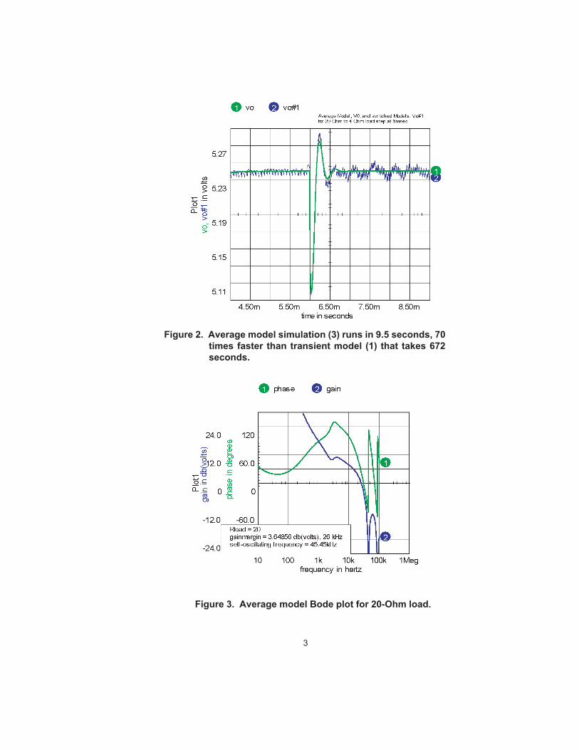
Bode plots for different loads reveal about the same gainand phase margin with the critical frequency runningabout .5 times the limit cycle frequency. For a load of 20Ohms, the frequency for 0dB gain was 26kHz and theswitching frequency was 45.4kHz, as shown in Figure 3.
The drain current pulse is formed by charging the Flybackinductance until the voltage across Rsense reaches a fixedthreshold. When that occurs, the PWM switch is turnedoff. The PWM is held off until the next clock pulse afterthe output voltage drops below the set point. This loopoperates in discontinuous conduction mode so that theoutput and input currents are given byD*.5*L*Imax^2*F/Vout and D*.5*L*Imax^2*F/Vin re-spectively.
For a constant input voltage and load current, the PWMon time is fixed and the duty ratio is controlled by the OFFtime. The self-oscillating frequency exhibits somesubharmonic oscillation because the internal oscillatorsynchronizes the turn-on, which is 100KHz for the deviceshown.
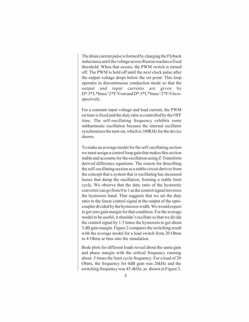
To make an average model for the self-oscillating sectionwe must assign a control loop gain that makes this sectionstable and accounts for the oscillation using Z-Transformderived difference equations. The reason for describingthe self-oscillating section as a stable circuit derives fromthe concept that a system that is oscillating has increasedlosses that damp the oscillation, forming a stable limitcycle. We observe that the duty ratio of the hystereticconverter can go from 0 to 1 as the control signal traversesthe hysteresis band. That suggests that we set the dutyratio to the linear control signal at the output of the opto-coupler divided by the hysteresis width. We would expectto get zero gain margin for that condition. For the averagemodel to be useful, it shouldn’t oscillate so that we dividethe control signal by 1.5 times the hysteresis to get about3 dB gain margin. Figure 2 compares the switching resultwith the average model for a load switch from 20 Ohmsto 4 Ohms at 6ms into the simulation.
3
Figure 3. Average model Bode plot for 20-Ohm load.
Figure 2. Average model simulation (3) runs in 9.5 seconds, 70times faster than transient model (1) that takes 672seconds.

4
A new Spice element was needed to account for thevariation in switching frequency with load. To accomplishthis, a code model was made with a variable delay timeconnected to an input port. In the time domain, it’s just adelay, outputting the historical data according to the re-quested delay. In the frequency domain, it’s an e^-sTfunction (Z^-1). It’s combined with a continuous Laplaceintegrator using a subcircuit model to make a fraction orderhold, FOH [1], that works in both the frequency domain andthe time domain. The FOH is a generalized model that canbe used to simulate a Zero order hold (k=0) on up througha first order hold (k=1) and anything in between. We usedk=0 for this model. By properly accounting for large signaldependencies in the difference equations, this “average”model is also a large signal model capable of studying turn-on, line and load steps and other large signal behavior. Theimproved simulation speed enables us to use the ICAP/4optimizer to center the design, getting the best performanceby selecting just the right component values.
With the following definitions, we can develop equationsthat describe the average model:
IC=charging current, secondary sideIA=average current primary sideIL=load currentTON=charging time, secondary sideTOFF=discharging time, secondary sideDV=output voltage hysteresisCL=load capacitanceLP=primary side inductanceN=turns ratio (Nsec/Npri)
The equations we need are then:
TD = TON+TOFFTON=CL*DV/(IC-IL)TOFF=CL*DV/ILTD = CL*DV*(IC/((IC-IL)*IL)

5
Discussion of Use and Limitations
The actual circuit cannot have an exactly correct duty ratiofor each cycle because of the 100kHz clock synchronizing.The duty ratio wanders around the correct result, producingsubharmonic content and a more accurate average valueover longer time intervals. This behavior is not expected toproduce serious errors, especially in determining stabilitymargins with respect to filter and load characteristics.
The discontinuous conduction assumption is violated dur-ing start-up, so that it is necessary to add mode-switchinglogic. We’ll do that in a later 8.x.11 software release alongwith time domain validation of the “average” model usingnew GFT software techniques. See the article “2003 BringsNew Software Updates, Server License and MacintoshProduct” on pg. 13 of this newsletter. Or watch our productpreview at the Applied Power Electronics Conference,February 9-13, 2003 in Miami.
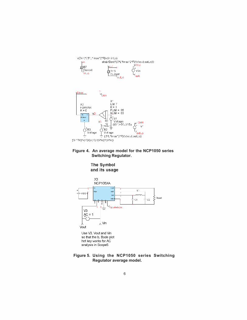
The NCP105XA model delivered with the ICAP/4 soft-ware is shown in Figure 4 and its use is illustrated in Figure5. In its initial release the under voltage lockout and shortcircuit protection is not included. The new FOHvar modelneeds the updated cml.lib, power.dll and updated symbollibraries. All are available to registered users with currentmaintenance from Intusoft at http://www.intusoft.com/support.htm
To use the average model, you need to place power.dll into<IcapsDir>\is\power.dll. Library onicavg.lib contains amodel for the NCP105X power converter called
But IC is known because the charging inductor is running indiscontinuous conduction, dumping ½*LP*Ipk^2*F power; sothat:
IC* VOUT = ½*LP*Imax^2*FIC = ½*LP*Imax^2*F/VOUT
And IL can be measured so that TD can be computed.
6
Figure 4. An average model for the NCP1050 seriesSwitching Regulator.
Figure 5. Using the NCP1050 series SwitchingRegulator average model.

7
NCP105XA and its symbol is in ONICAVG.sym.Models vardelay and FOLvar are in cml.lib use power.dllto account for the changing frequency with operatingpoint.
There are certain cases for which DC convergence failsbecause of singularities in the DC operating point. A zeroorder hold is an example that cascades a z transformdifferentiator with a Laplace integrator. The resultantproduct of 0 times infinity produces a non-convergent DCresult; however, an AC crossover network eliminates theproblem node so that it is fair to remove it from theconvergence test. R3 and C1 shown in Figure 6 bypassesthe DC solution that otherwise cascades S-planeintegration with Z domain differentiation.
New Spice Convergence Aid
Figure 6. A variable delay Fraction Order Hold.

8
Back in March 2001, Newsletter 62 illustrated IsSpicetechniques for measuring Two-Port network parametersfor various sets of network equations. The very lasttopology was the transmission or T parameters. To evalu-ate these T parameters, a SPICE3 behavioral element wasused to adjust the voltage at one port so that the opencircuit voltage at the opposite port becomes unity. Wedidn’t explain why this should work and as it turns out theuse of this technique is also central to application of theExtra Element Theorem [2] using a SPICE simulator. In thelab, adjusting in-phase and quadrature signals to achievethe desired result does this. All that’s necessary is thepresence of a network to transmit the signals from the
Increasing VNTOL can remove the non convergent be-havior; however, VNTOL is global and increasing it tosolve the problem at one node will reduce the DC operat-ing point accuracy. If the user were to manually enterVNTOL for each node, the bookkeeping managementwould become difficult. Intusoft has introduced a newIsSpice option, AUTOTOL. An array of values holdingvntol[ ] and abstol[ ] for each node and source current isinitialized with the VNTOL and ABSTOL values. IfAUTOTOL is set larger than 1, then when a node or branchcurrent fails to converge, its tolerance value is multipliedby AUTOTOL. Setting AUTOTOL=2 will rapidly elimi-nate offending nodes. Smaller values will make theelimination occur more slowly and have a less sever affect.If AUTOTOL is set to less than -1, the same thing occursusing the absolute value of AUTOTOL and the “.OUT”file reports the activity so that you can isolate problemnodes and sources. AUTOTOL is only active for the initialDC operating point calculation. To use the AUTOTOLoption; enter .options AUTOTOL = [value] in the userstatements field of the IsSpice4 simulation setup dialog.
Nulling Techniques AidCircuit Analysis
9
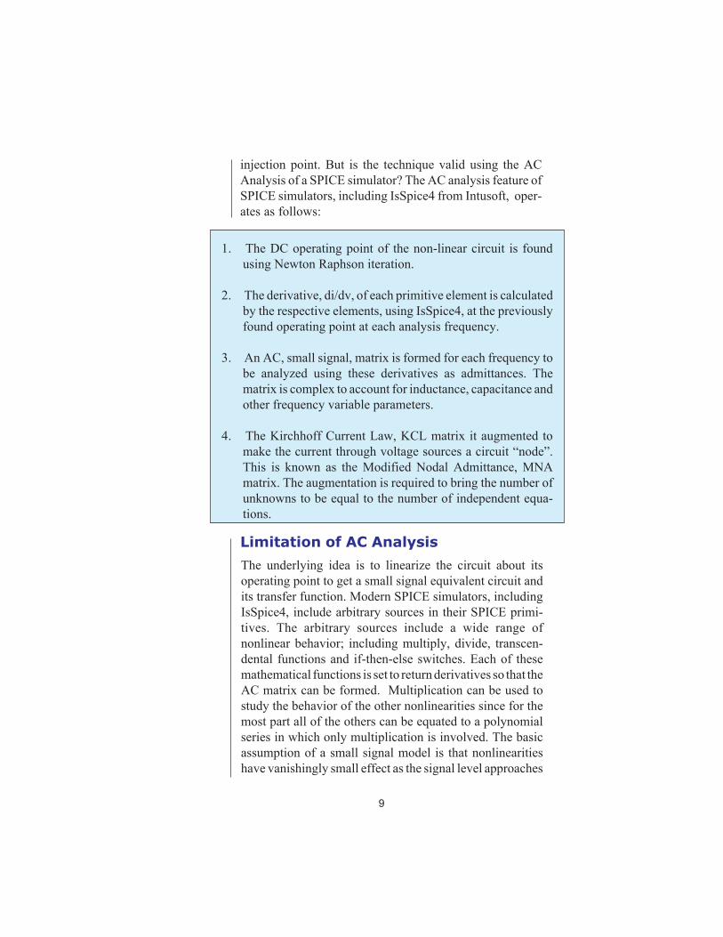
injection point. But is the technique valid using the ACAnalysis of a SPICE simulator? The AC analysis feature ofSPICE simulators, including IsSpice4 from Intusoft, oper-ates as follows:
1. The DC operating point of the non-linear circuit is foundusing Newton Raphson iteration.
2. The derivative, di/dv, of each primitive element is calculatedby the respective elements, using IsSpice4, at the previouslyfound operating point at each analysis frequency.
3. An AC, small signal, matrix is formed for each frequency tobe analyzed using these derivatives as admittances. Thematrix is complex to account for inductance, capacitance andother frequency variable parameters.
4. The Kirchhoff Current Law, KCL matrix it augmented tomake the current through voltage sources a circuit “node”.This is known as the Modified Nodal Admittance, MNAmatrix. The augmentation is required to bring the number ofunknowns to be equal to the number of independent equa-tions.
Limitation of AC Analysis
The underlying idea is to linearize the circuit about itsoperating point to get a small signal equivalent circuit andits transfer function. Modern SPICE simulators, includingIsSpice4, include arbitrary sources in their SPICE primi-tives. The arbitrary sources include a wide range ofnonlinear behavior; including multiply, divide, transcen-dental functions and if-then-else switches. Each of thesemathematical functions is set to return derivatives so that theAC matrix can be formed. Multiplication can be used tostudy the behavior of the other nonlinearities since for themost part all of the others can be equated to a polynomialseries in which only multiplication is involved. The basicassumption of a small signal model is that nonlinearitieshave vanishingly small effect as the signal level approaches
10
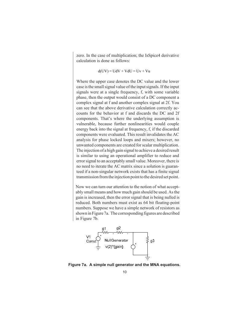
Now we can turn our attention to the notion of what accept-ably small means and how much gain should be used. As thegain is increased, then the error signal that is being nulled isreduced. Both numbers must exist as 64 bit floating-pointnumbers. Suppose we have a simple network of resistors asshown in Figure 7a. The corresponding figures are describedin Figure 7b.
zero. In the case of multiplication; the IsSpice4 derivativecalculation is done as follows:
d(UV) = UdV + VdU = Uv + Vu
Where the upper case denotes the DC value and the lowercase is the small signal value of the input signals. If the inputsignals were at a single frequency, f, with some variablephase, then the output would consist of a DC component acomplex signal at f and another complex signal at 2f. Youcan see that the above derivative calculation correctly ac-counts for the behavior at f and discards the DC and 2fcomponents. That’s where the underlying assumption isvulnerable, because further nonlinearities would coupleenergy back into the signal at frequency, f, if the discardedcomponents were evaluated. This result invalidates the ACanalysis for phase locked loops and mixers; however, nounwanted components are created for scalar multiplication.The injection of a high gain signal to achieve a desired resultis similar to using an operational amplifier to reduce anderror signal to an acceptably small value. Moreover, there isno need to iterate the AC matrix since a solution is guaran-teed if a non-singular network exists that has a finite signaltransmission from the injection point to the desired set point.
Figure 7a. A simple null generator and the MNA equations.
11
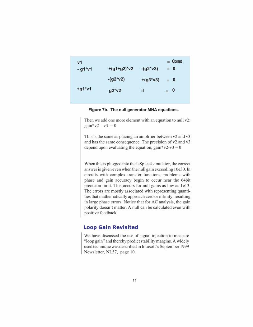
Figure 7b. The null generator MNA equations.
Then we add one more element with an equation to null v2:gain*v2 – v3 = 0
This is the same as placing an amplifier between v2 and v3and has the same consequence. The precision of v2 and v3depend upon evaluating the equation, gain*v2-v3 = 0
When this is plugged into the IsSpice4 simulator, the correctanswer is given even when the null gain exceeding 10e30. Incircuits with complex transfer functions, problems withphase and gain accuracy begin to occur near the 64bitprecision limit. This occurs for null gains as low as 1e13.The errors are mostly associated with representing quanti-ties that mathematically approach zero or infinity; resultingin large phase errors. Notice that for AC analysis, the gainpolarity doesn’t matter. A null can be calculated even withpositive feedback.
=
0
0
v1 =
=
=Const
- g1*v1 +(g1+g2)*v2 -(g2*v3) 0
-(g2*v2) +(g3*v3)
+g1*v1 g2*v2 il
Loop Gain Revisited
We have discussed the use of signal injection to measure“loop gain” and thereby predict stability margins. A widelyused technique was described in Intusoft’s September 1999Newsletter, NL57, page 10.
12
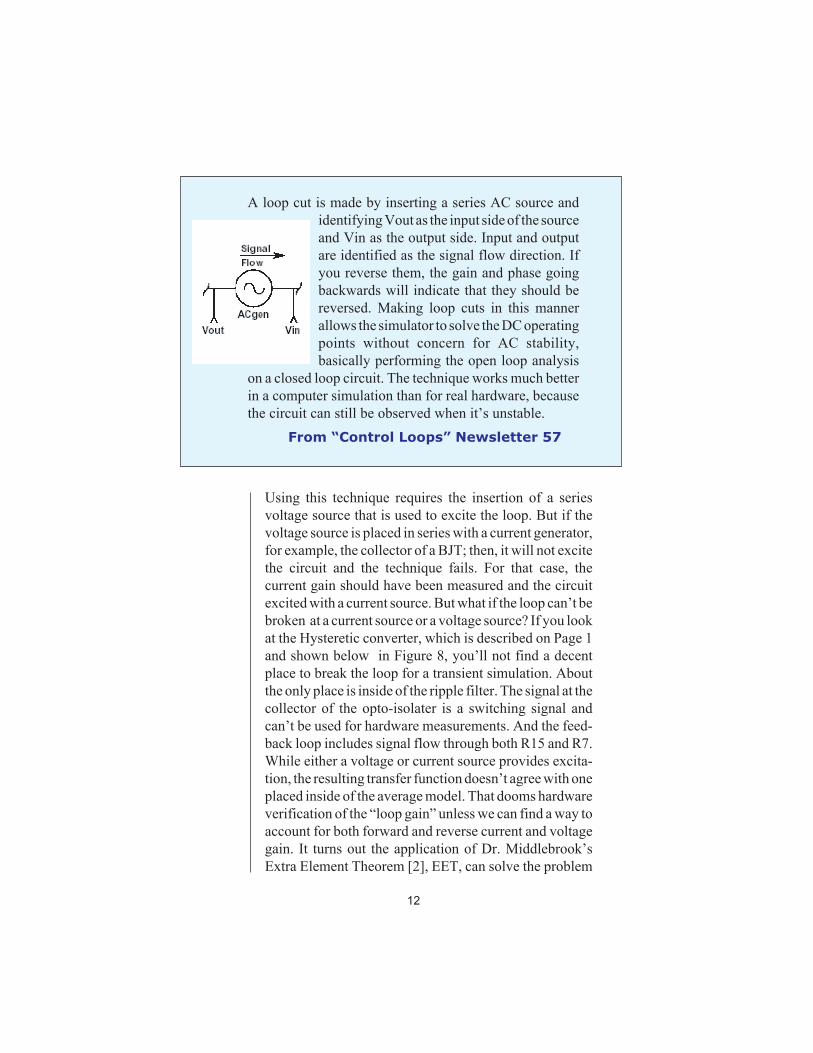
A loop cut is made by inserting a series AC source andidentifying Vout as the input side of the sourceand Vin as the output side. Input and outputare identified as the signal flow direction. Ifyou reverse them, the gain and phase goingbackwards will indicate that they should bereversed. Making loop cuts in this mannerallows the simulator to solve the DC operatingpoints without concern for AC stability,basically performing the open loop analysis
on a closed loop circuit. The technique works much betterin a computer simulation than for real hardware, becausethe circuit can still be observed when it’s unstable.
From “Control Loops” Newsletter 57
Using this technique requires the insertion of a seriesvoltage source that is used to excite the loop. But if thevoltage source is placed in series with a current generator,for example, the collector of a BJT; then, it will not excitethe circuit and the technique fails. For that case, thecurrent gain should have been measured and the circuitexcited with a current source. But what if the loop can’t bebroken at a current source or a voltage source? If you lookat the Hysteretic converter, which is described on Page 1and shown below in Figure 8, you’ll not find a decentplace to break the loop for a transient simulation. Aboutthe only place is inside of the ripple filter. The signal at thecollector of the opto-isolater is a switching signal andcan’t be used for hardware measurements. And the feed-back loop includes signal flow through both R15 and R7.While either a voltage or current source provides excita-tion, the resulting transfer function doesn’t agree with oneplaced inside of the average model. That dooms hardwareverification of the “loop gain” unless we can find a way toaccount for both forward and reverse current and voltagegain. It turns out the application of Dr. Middlebrook’sExtra Element Theorem [2], EET, can solve the problem

13
Figure 8. The loop cut shown between R4 and L1 is neither avoltage nor current driven injection point.
2003 Brings New Updates,Server License and Mac Version
New Usability Enhancements
Intusoft is set to release on February 17, Version 8.x.10,Build 1989, of the ICAP/4Windows family of software. Apreview will be shown the week before at APEC in MiamiBeach. This preview will cover things like:
Easy project switching- No longer do you need toclose all open schematics to change your active project. Thecurrently selected schematic becomes your active project.
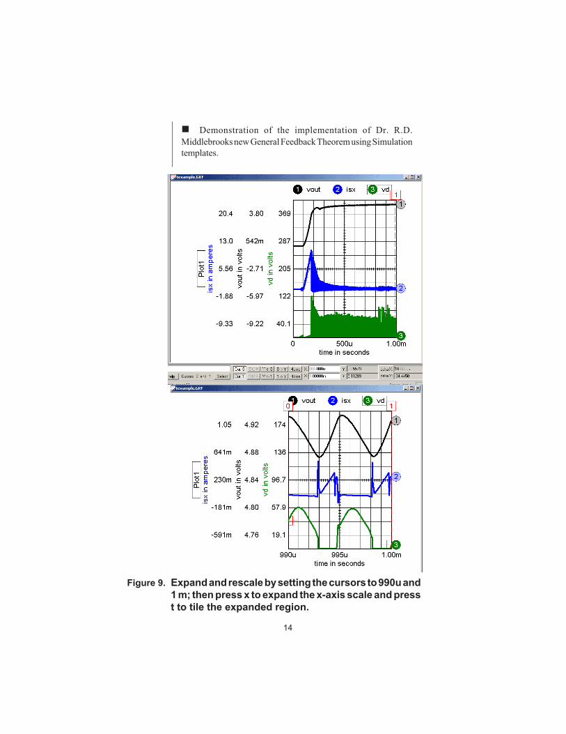
IntuScope5 region based tiling- Tile region betweencursors 0 and 1, as seen in Figure 9.
by making measurements using null injection that we alsodiscussed earlier. We explore this problem in our nextnewsletter and demonstrate the technique at the AppliedPower Electronics Conference (APEC 2003) this Febru-ary in Miami Beach, Florida.
14
Demonstration of the implementation of Dr. R.D.Middlebrooks new General Feedback Theorem using Simulationtemplates.
Figure 9. Expand and rescale by setting the cursors to 990u and1 m; then press x to expand the x-axis scale and presst to tile the expanded region.
15
The Mac is Back!
ICAP/4 can now be run on the Apple Macintosh Computersby using Connetix Virtual PC 6.0. Try it out on the demothat’s on our web site. Be sure to order the Mac version, ituses a virtual key instead of a hardware dongle. Intusoft firstdeveloped for the Macintosh in September of 1989.
Ordinarily, IsSpice runs on the users workstation, evenwhen a network license is purchased. To facilitate web-based services, Intusoft has now made available a versionof its ICAP/4 package that is licensed to run remotely on aserver. The software includes Icaps.exe, Spice4.exe andassociated libraries. Typical use of such a package is to runcanned topologies with minor variations that showcasethird party products. For this usage to make sense, prob-lems must be small so that latency will be acceptable.(Latency is the time elapsed between a request for webservice and the returned data.). Licenses are issued for 1,2,3and 4 processors per server machine. The software isavailable for Windows NT and XP. The licenses are soldper processor and are time locked for one year at a time.Two pricing models are available. First, you can purchasethe software under our current agreement and keep it activewith an annual fee (about 15% per year). Secondly, you canpurchase an annual license only. The second option isconsiderably less expensive for the first year; however, byyear 4 it costs more. The advantage is that you can chooseto add more licenses at any time so you can easily balanceyour web service with customer demand.
Web and Client-Server Networking
[1] Benjamin C. Kuo, 1963, Analysis and Synthesis ofSampled Data Control Systems, pg 49-51.
[2] R.D. Middlebrook, V. Voperian and J. Liu, IEEETransactions on Circuits and Systems, September 1998,The N Extra Element Theorem

16
Intusoft’s World-Wide Support StaffListed below are dealers where Intusoft products, updates, information, and support may be obtained.
CMR Design Automation - Mahesh ChandraIndiaTele: 91 11 6477085/Fax:91 11 6213498email - [email protected]
ChipCAD - Tibor BerkyHungaryTele: 36-1 231-7000/FAX: 36-1 231-7001email - [email protected]: http://www.chipcad.hu
IVIS Co., Ltd. - Hiro NaganoJapanTele: 81-45-332-5381/FAX: 81-45-332-5391email - [email protected]: http://www.i-vis.co.jp
EDA Software - John MeltezosGreeceTele: 30-210-825-6258 or 6259/FAX: 30-210-884-1016email - [email protected]
INTSYS Europe SA - Claude MasseboeufFrance, Tunisia, Algeria, MoroccoTele:(33)01-60-81-00-69/FAX:(33)01-60-81-00-70email - [email protected]: http://www.intsys-europe.fr
DFM - Tuvia LiranIsraelTele: 972-4-9533059/FAX: 972-4-9533057email - [email protected]: http://www.dfm4vlsi.com
Dahan Tech Inc. - Sang Y. ChoSouth KoreaTele: 82-2-515-2845/FAX: 82-2-515-2844email - [email protected]: http://www.dahan.co.kr
Technology Sources Ltd. - Dr. Graham PlowsDenmark, Spain, Portugal, Norway, Sweden, UKTele: 44-01223-516469/FAX: 44-01223-729-916email - [email protected]: http://www.softsim.com
DS-Design Systems OY-Hannu TikkanenFinlandTele: 358-14-652588/FAX: 358 -14-610725email - [email protected]: http://www.designsystems.fi
Thomatronik GmbH - Herbert M. MüellerGermany,Austria,Croatia,Slovenia,CzechRep.Tele:49 -8031-2175-0/FAX: 49- 8031-2175-30email - [email protected]: http://www.thomatronik.de
Cho Chieh Enterprise Ltd. - Tennyson LinTaiwan, Hong Kong, China, Southeast AsiaTele: 886-2-2981-2187FAX: 886-2-8983-5229email - [email protected]: www.chochieh.com.tw
COREDA Corporation - Monique MassereyWestern CanadaTele: (905) 566 - 1755Tele: (877) 566 - 1755 Toll FreeFAX: (905) 566 9925e - m a i l : m o n i q u e m @ c o r e d a c o r p o r a t i o n . c o m
TECH 5 - Geert MosterdijkNetherlands, Belgium, LuxenburgTele: 31-184-6155-51/FAX: 31-184-6154-51Tele:32-2-657-31-64/Fax:32-2-657-49-25 Belgiumemail: [email protected]/[email protected]: www.tech5.nl/[email protected]
Intusoft Inside Sales :879 West 190th StreetSuite 100Gardena, CA 90248-4223Tele: (310) 329-3295Fax: (310) 329-9864e-mail: [email protected]
EDAforce , Inc - Jean GodboutEastern CanadaTele: (450) 622-5500 FAX: (450) 629-4211Toll Free 888-466-5834e-mail: [email protected]: www.edaforce.com
CAREL - Cezary RudnickiPolandTele/FAX: (0-22) 624-06-19e-mail: [email protected]: www.carel.waw.pl
Siscad s.r.l.- Valerio ScibiliaItalyTele: 39-02-48022546/FAX: 39-02-48015146email - [email protected]: http://www.siscad.it