i. p. n. - 91406 orsay cedex a zj ça - iaea
TRANSCRIPT

I. P. N. - 91406 ORSAY CEDEX
aZJça
toQC
•LU
CO
ECM
COQC
IPNO-DRE 93-31
GAS FILLED DETECTORS
Claude STEPHAN
To be published in Handbook of Nuclear Decay Modes,edited by D. N. Poenaru and W. Greiner,CRC Press, Boca Raton, Florida.

IPNO-DRE 93-11
GAS FILLED DETECTORS
Claude STEPHAN
To be published in Handbook of Nuclear Decay Modes,
edited by D. N. Poenaru and W. Greiner,CRC Press, Boca Raton, Florida.

GAS FILLED DETECTORS
Claude STEPHAN
INSTITUT DE PHYSIQUE NUCLEAIRE
CNRS-IN2P3 Université Paris-Sud ORSAY, FRANCE
I. INTRODUCTIONII. BASIC PROCESSES INVOLVEDA. Energy loss in gas
B. The relation between energy deposited and charge collection
III. IONIZATION CHAMBER.A. Principle of operation
B. Various designs of ionization chambers.
IV. PROPORTIONAL COUNTERS.A. Principles of operation.
B. Gas operation.
C. Various types of proportional counters.
V. LOW PRESSURE GAS DETECTORSA. Parallel plate avalanche chambers.
B. Low pressure multiwire proportional counters.
C. Low pressure multi-step detectors.
VI. GAS MICROSTRIP DETECTORS
A. Description.
B. Influence of the substrate and nature of electrodes.
C. Performances.
VII. CONCLUSION

I. INTRODUCTIONGas detectors are among the oldest and widespread types of instruments used in nuclear
physics. They have found a regain of interest in the early 1970's with the acceleration of heavyions which introduced new requirements: thin entrance windows, low pressure of operation,detectors set in vacuum, and chiefly the ability to work at the same time with particles withvery different values of atomic number. They are radiation insensitive and they can competeadvantageously with scintillators or solid state detectors which present pulse height defectsincreasing with Z, shortened life time due to large energy losses in the detector, small active
areas. Gas detectors are extremely versatile: they can handle high counting rates and beused for energy measurements, position determination or for timing with all types of chargedparticles, and even with 7 and X rays. They can easily fit every experimental condition and be
built at a relatively low price although in large dimensions with the advantage to eventually berepaired on site during an experiment. Their disadvantages are essentially a relatively limitedenergy resolution and the necessity of a gas filling which might eventually mean leak or window
problems. The main types of gas detectors, ionization chambers, proportional counters, andavalanche counters, which have become routine tools, will be described. Complex designs andnew devices are also advocated. For a better understanding of their operating way, a resume
on the processes involved in such detectors is given.
II. BASIC PROCESSES INVOLVEDThe processes involved in gas detectors have been extensively studied and are now well
understood. A charged particle traversing a gaseous medium interacts essentially with it byCoulomb interactions. The electromagnetic field of the particle will produce excitation and
ionization when interacting with the outer electrons of the atoms of the gas. The energyloss results of these discrete interactions between the projectile and atoms from the medium.These primary collisions then create electron-positive ion pairs which again will be able to
interact with the medium. The characteristics of the signals from the different types of gascounters are strongly related to the created number of primary pairs. In the absence of othereffects, ionic charges will rapidly loose their energy by multiple collisions with gas moleculeswhile electrons will diffuse in the medium.

A. Energy Loss in Gas
Many review articles have been written on the subject of charged particle energy loss inmatter.1"2
1 . Light particle energy loss
The energy loss of particles depends on the energy transferred to electron of gas moleculesduring the interaction. The quantitative evaluation of the energy loss dT per length unit dXhas been described a long time ago by Bethe and Bloch in the framework of relativisticquantum mechanics by the formula:
dT 47Te4Z2 F 2muF2
dxwhere Z is the atomic number of the medium, / is its effective ionization potential whichcan be taken with a good approximation as J = IUZ, where /u = 12 eV; n is the number ofinteractions per volume unit, mu and e are the electron mass and charge, V and z are thevelocity and charge state of projectile, /3 = VJc . CK represents inner shell corrections andcan usually be neglected.
In this equation (1) the projectile energy loss is a function of its velocity and not ofits energy. The stopping power is then the product of two factors, one is a monotonicallydecreasing function of the velocity of the projectile, the second ( between braces) increaseslogarithmically with it. This second term is responsible for the relativistic rise of the stoppingpower. If the energy is expressed in MeV and the thickness of the medium in gcm~2 onefinds
= 0.307/3-V/4 MeV/gcm-2 (2)A
A, p, are respectively the mass and density of the medium. For molecular gases or mixtures,one takes average values for A, Z, and / in the Bethe formula.
2. Heavy ion energy loss
The Bethe formula (1) predicts with a good precision proton and alpha particle energylosses. Presently gas detectors are mostly used in nuclear physics for heavy ions. In order toapply the formula to these particles it is necessary to know the charge state z of the projectile.Indeed it depends on the energy of the ion and on the traversed medium. It means that zwill even vary during its path in the gas when decelerating. This renders in most cases theformula (1) almost unusable for heavy ions. As stopping powers and ranges play an importantrole in many aspects of heavy-ion physics, semi empirical tables of energy loss of heavy ionshave then been established by means of a scaling law based on a compilation of hundredsof experimental data.3"0 The most recent tables by Hubert et al.° have used the followingparameterization equations where alpha particles are chosen as reference projectiles.

Sion =(71.2^1)2
ton
IHe
with
71,2 =-0.88V
7i = l-A( Zi)exp 65
(3)
(4)
(5)
100
£0 10O)
O)2
0.1
ion —- Arthis worki « ims work
cxp 1+ Bimbot el ol
F.S.Hubert et alZiegler
20 40 60E/A (MeV/u )
80
Figure 1. Variation of the stopping power of Argonfor O, Ar, Kr and Xe ions venus incident energy. The
experimental points (full dots) are compared with cal-
culated curves from Ziegler ( dotted lines)1, from fullystripped approximation ( solid lines) and from an effec-tive charge parameterization valid for solid media (bro-
ken line)5. From Hérault et al.7

2.5 MeV/u and 500 MeV/u in a large sampling of solids. For gases, the authors find theirtabulation valuable when the ions are fully stripped, but the energy loss of gases is decreasedby 20% for ions which have a broad charge state distribution. This effect was first observedby Geissel et al.° in 1983. Figure 1 shows such differences obtained by Hérault et al.' for theenergy loss of Xe ions in argon. The authors interpret the difference by a density effect insolids.
3. Photon interactions
Gas detectors can also be used to detect gamma and X rays. Three major types of inter-action mechanisms lead to the partial or complete transfer of the photon energy to electronenergy: photoelectric absorption, Compton scattering and pair production as described inchapter X. In contrast with charged particles which loose gradually their energy, here theseprocesses result in sudden energy deposit in the gas. The choice of the gas filling will then bedetermined essentially by its absorption capability, in order to get a high detection efficiency.
B. The relation between energy deposited and charge collection
1. Number of ion pairs created
Regardless of the detailed mechanisms involved, the practical quantity of interest is thetotal number of ion pairs created along the track of the radiation. The minimum energy/ii which can be transferred for each interaction is between 10 and 20 eV, correspondingto the ejection of the least tightly bound electrons. However, other mechanisms like atomexcitation which happen in distant collisions can lead to an energy loss of the incoming particlewithout removal of an electron from the gas molecule. Therefore, the average energy W whichcorresponds to an ion pair creation is substantially greater than the ionization energy. Theparameter W does not depend much on the particle, its energy or even the nature of the gas.This feature is illustrated in table 1 where values of W for alpha particles, 340 MeV protonsand 0 rays are given.1'8
From table 1 one can deduce that a 10 MeV particle will create about 3.103 ion pairs.There are fluctuations on the number of these ion pairs and these fluctuations can haveimportant consequences on the energy resolution of the detector. It is necessary to distinguishtwo cases: when the particle deposits a large amount of energy in the detector or when itleaves in it only a small part of its total energy. In the first case, many gas detectors showan inherent fluctuation which is less than predicted by Poisson law. It simply means thatwhen an important part of the energy of the particle is lost in the gas, there is a correlationbetween the number of collisions experienced by the particle and the energy lost at average ineach collision.The Fano factor is introduced as an empirical constant by which the varianceso found has to be multiplied to give the experimental value.1

In the other case, the ion pair fluctuations can conduct to serious limitations for thin lowpressure detectors in which there are very few primary ionization events following Poisson-like statistics. As there are large fluctuations in the energy loss per impact, measured energylosses are broader than expected by a statistical variance only.9 The energy loss distributionsare characterized by an asymmetry with an excess of large energy losses as predicted byLandau and Vavilov.10"11. The relative probability of different processes induced by 31.5MeV protons in a proportional counter are represented in figure 2.
Figure 2. Frequency distribution of energylosses of 31.5 MeVprotons traversing proportional
counter filled with 96% Ar and 4% CO2. The
histogram of experimental points is compared tothe theoretical Landau distribution and a gaussian
distribution based on ion-electron pair statistics.From Igo et al.12
TABLE 1
S- 200
nr IHN SIMPLE T*-£OfiV IGfiUSS;JlMI•V'. L«ND«U TMEOnv -j*! - ; >-L EXPERIMENTAL POINTS
MOST PROBABLETOTAL ENERGY LOSS
/MfiîCIMUV Er.EflG> LCSil" SiNG-E Cai—ISICI
C SCURJlTS
Effective, ionization potential Io(eV) and values of W(eV/ion pair) in various gases fora,/? rays and 340 MeV protons. From FANO,1 and from SAULI,6 where references are given.
gases
HeNeAr
KrXeH2
N2
O2
CO2
CH4
C4Hm
/O
24.621.615.814.012.115.415.512.213.713.110.8
a rays
42.736.826.424.1
21.936.336.432.534.029.0
W/3 rays 340 MeV protons
42.336.626.424.2
22.036.3 36.534.9 34.730.9 32.632.927.3
23

2. Ion Drift
In gas detectors an electric field is applied across the gas volume inducing motion ofions and electrons along the field direction, named the drift velocity w. It results in a slowmovement linearly proportional to the electric field E and inversely proportional to the gaspressure P. Table 2 gives experimental mobilities of several ions in different gases where themobility /z is defined by the formula
ijiw = ft- (6)
TABLE 2
Experimental mobilities of several ions in different gases, at normal conditions.13
Gas
Ar
(OCHs)2CH2
ArZ-SoC4-ET10
ArCH4
ArCO2
Ions
/~\f~* TT \ /~1 TT-T*Lx vx Jl 3/2 ̂ ^ -*̂ *)
(OCHs)2CH+
OCHs)2CH+
isoC4H+
u
isoC4Hl()
CH+
CH+
CO+
CO2-
Mobility
1.510.550.261.560.611.872.261.721.09
3. electron drift
The maximum energy Tm of electrons results from a collision between the projectileand an electron from the medium following a two body kinematics. Ejected electrons have astatistical energy distribution of the form
A ) (7)
In this formula due to Landau,10 A represents the normalized deviation from the most prob-able energy loss. These electrons, named 8 electrons at the time of nuclear emulsions, areemitted at an angle given by a free electron approximation cos2 6 = -f-. They will then driftin the gas volume. Due to their small size, the collisions with molecules of the medium aremuch less probable than for ions. Therefore these electrons move much faster in gas thanions by a factor 1000. Typical collection times in detectors are of the order of microsecondsas compared to milliseconds for ions. In a formulation due to Townsend,14 the drift velocityw can be written
r (8)» =

where r is the mean time between collisions. The electron-atom cross sections vary withenergy, due to complex quantum effects between the free electron and the electron shells ofgas molecules. It means that T will depend strongly on the electric field E and consequentlythe shape of the electron energy distribution is also E dependent. As an example, the driftvelocity w of electrons through the gas of an ionization chamber, is about 5.106 cm/s.
Multiple collisions undergone by electrons during the drift outcome as a diffusion in thegas. Following the kinetic theory of gases, the proportion of electrons =j£- found in the elementdx, at the distance x from the origin after a time t , is given by a Gaussian distribution-likeformula
(9)N
where D is the diffusion coefficient; changes in the electron energy distribution due to thepresence of an electric field result in a diffusion coefficient D dependent on the electric fieldE. This diffusion will result in a collection on a wider surface which will affect the position
resolution. A small diffusion coefficient leads to a better position resolution
4. Recombination
Some of the many collisions of free electrons with gas atoms during the drift may resultin charge neutralization. Recombination probability depends on charge carrier density andgas pressure. This process is of importance since the original charge is lost and will notcontribute to the collected ionization signal. It can even happen that the free electron iscollected by a neutral atom, creating a negative ion.
Collisions between ions and neutral atoms of gas have still a much higher probabilityto happen due to their very small mean free path. Charge transfer is possible either with amolecule of its own gas or with molecules with lower ionization potential. In gas mixtures,this process is very effective and rapidly removes all ions except the ones with the lowerionization potential. Negative ions may recombine with positive ions resulting in neutralatoms. In worse case these negative ions contribute to reduce the collected signal with theiropposite charge.
5. The multiplication phenomenon
When a high electric field is applied on an electrode, the primary electrons acquirean energy larger than the ionization potential of the gas atoms. Thus, they can inducesecondary ionizations and the new free electrons can in turn be accelerated and producefurther ionizations, generating a small avalanche. The development of such an avalancheand its quenching depends on the intensity of the electric field and on the nature of the gasfilling. The gas mixture will be chosen in order to fulfill the experimental requirements, highgain, high counting rate, fast recovery, between others. More details are given in section IVdevoted to proportional counters.
8

Figure 3. The different regions of operation of
gas filled detectors. The pulse amplitude is plottedfor particles depositing a different amount of energywithin the gas.10
6. Different regions of operation of gas counters.
The collected charge is connected to the applied voltage difference between anode andcathode. Figure 3 after the Montgomerys in 1941 illustrates the different operating modes
following the value of this voltage difference.15 At very low voltage, recombination plays animportant role. When the voltage is increased, full collection can be reached and the detectoris said to be operating in the ionization chamber mode. If the electric field is still increased,near the anode surface a multiplication process begins and gains up to 104 are reached. Thedetector is said to be working in the proportional regime since the collected signal is stillproportional to the deposited charge. If the voltage is increased again, the proportionalityis gradually lost. Finally a saturated gain is reached in Geiger-Muller counters, or in certainconditions a new regime called the self quenching mode is obtained.
In the next sections the different types of detectors following these various modes willbe described and recent applications will be presented.
III. IONIZATION CHAMBERSlonization chambers have been described by many authors.16"18 They have been in
operation for a very long time and in their principle there were no significant changes sincethe beginning. This type of detector has regained interest since 1975 with the development ofheavy ion nuclear physics due to the very high stopping power of heavy ions. Consequentlyhardly feasible thin and homogeneous soh'd detectors ( scintillators and silicon detectorsmainly) can be advantageously replaced by gas chambers which in addition are radiationinsensitive. Electronic linear amplification improvements have made their use competitive.
1000

1000
A. Principle of operation
The most simple type of chamber will consist in two electrodes made of two parallel
plates maintaining a static electric field in between. In such chambers it is assumed that theapplied electric field is sufficient to eliminate recombination effects and that negative charges
are only due to free electrons. The constant electric field intensity E is given by the relation
E=^ (10)
where V is the voltage applied across the chamber electrodes distant by d. The situation is
sketched in figure 4.
Figure 4.Diagram of parallel plate ionization chamber.
Parameters d and x are shown.
c -:"-
We assume that a particle has produced n0 ion pairs at a distance x from the anode.
After a time te given by the electron drift, all the electrons have reached the anode. During
the same time the ions moved very little but induced a charge on the anode. The signal
voltage through a resistor denoted VR will then be
(U)U/ U
here C is the ionization chamber capacitance. By waiting long enough so that all ions be
collected on the cathode, the maximum expected signal is
*max — (12)
As these collection times are of milliseconds, for high counting rates, it is interesting to choose
a much shorter collection time constant so that the collected pulse reflects only the electron
drift. The output pulse as a function of time is represented in figure 5.
vR(t)4
Figure 5. Output pulse VR as a function of collection
time. The fast rise time corresponds to electron col-
lection, the broken line represents the shape of output
pulse with a time constant RC «C ion full time collec-
tion.
10

Unfortunately, the collected signal VR depends on the position x of the pair creations.To get rid of this dependence, Frisch has designed ionization chambers with a screening grid.
1 . The gridded ionization chamber
The dependence of the pulse amplitude on the position of the ion pair creation can beremoved with a chamber equipped with a "Frisch" grid. In this chamber the electrons have totraverse a grid set between the interaction volume and the anode. This grid is as transparentas possible, compatible with a good shielding efficiency. The grid is kept at an intermediatepotential. Thus the pulse amplitudes obtained from collected electrons are not changed bythe image charge of ions. An extensive study of grid effects by Buneman, Cranshaw andHarvey allows to evaluate the shielding efficiency of a Frisch grid.19
i . .where p = - (13)
*
In this formula, <r evaluates to which extent the grid will shield the collector anode fromthe electric field in the ionization chamber; p is the distance grid-anode, s is the wire interval,and a is the wire radius. For example, a Frisch grid made of wires 50 /Jm in diameter, 1 mmapart, distant from the anode by 1 cm and from the cathode by 5 cm, will give <r = 0.971.This value is very much satisfactory, since the grid has still a 95% mechanical transparency.Further, collection of electrons by the grid can be substantially avoided if the electric fieldset between grid and anode is somewhat larger than the ionization chamber electric field. Alllines of electric field by-pass the grid under the condition (14) derived by Buneman et al.19
VP -Va p + pp + 2trpp~ { 'VG-VA ~ d-pd-2<rpp
In this condition valuable for efficient shielding (tr should be close to 1) V^, VG > Vp are,respectively, the potentials applied to anode, grid and cathode; d is the distance grid-cathode.
2. Wall and window effects
The metallic walls of the chamber at a potential V = O distort the lines of force of theelectric field, and consequently a fraction of the electrons are not collected. If walls are madeof isolating material the situation is still worse since their potential can change with positionand time, due to electrostatic charging up. This problem has been solved a long time agowith a guard ring surrounding the collector electrode on all sides. This name comes fromthe days when most often the ionization chambers were cylindrical, with a radioactive sourcedeposited on one of the electrodes. Nowadays, usually the detected particle is emitted by anirradiated target from outside a parallelepipedic chamber. The particle reaches the ionizingvolume through a window made of a thin plastic film.
11

Guard rings on the edges reduce the size of the effective volume. In front of the entrancewindow, they create a dead section where the energy of the particle is not measured. A cleversolution consists to constitute an electric shielding with wires or aluminum strips evaporatedon a plastic foil at a potential which varies linearly between the potentials of both electrodes.The efficiency of the shielding is a function of the distance between strips. A reasonableevaluation is to consider that electric field inhomogeneities disappear at a distance five times
larger than the distance between strips.20
3. Observed signals
These detectors are mostly used in nuclear physics to detect heavy ions, to measure theirtotal energy E, but also their energy loss AE in a small part of their total range, in orderto determine their atomic number Z. As compared to solid state detectors, no pulse heightdefect on the heavy ion mass can be observed.21 Indeed, the energy loss in a given mediumthickness is a function of Zc with c ~ 2. For this purpose, the anode is split in two or moreparts to be able to identify in Z and measure the energy of all the heavy ions of interest.22
In addition the gas pressure can also be adjusted.
A schematic drawing of a typical chamber is represented in figure 6, showing the differentelectrodes, the electric shielding and typical voltage values.23
I IJMl—• W>-—f +!
10OnFSSMn [-SOOv
24 x 1.2 MfI
5.6Mn
Figure 6. Schematic drawing of a parallel plate ionization chamber, showing the splittingof anode in 3 parts and the potential distribution on the entrance window. The given voltagesare for a 5 cm wide ionization space filled with isobutane at a pressure of 0.2 atmosphere.23
Signals on the anodes due to electron collection must be amplified. The contributionof the electronic noise to the resolution is small in most cases, (10""* of the collected signaltypically). The actual resolution of the energy measurement is then given essentially bythe fluctuations in the number of collected electrons and by energy straggling. For the
12

total residual energy left in the detector, a resolution better than 1% is always obtainedand resolutions of 0.3 % can be achieved. In the evaluation of the total energy loss in theionization chamber one must be aware that the entrance window is not usually flat due thegas pressure inside the chamber and vacuum outside.24 As s result the residual energy left inthe chamber will vary with the position height and should be taken into account.
Energy loss resolutions may not be as good for heavy ions as they use to be for lightparticles. This fact is connected with the charge state distribution of the projectile during itspath through the medium. The charge state of the particle is determined by the competition
between various atomic collisions processes, essentially electron capture, ionization, whichcross sections depend on the relative velocities of the projectile and the bounded electroninvolved.25 When velocities are similar, the projectile may undergo a few charge state changesduring its trajectory inside the gas. Each time the stopping power will be modified. It means
that each particle might have a different energy loss in a given gas volume. This is not truefor the full range since all the energy of the particle is measured whatever the succession ofinvolved processes, but is important when gases are used to identify the atomic number ofthe particle by energy loss determination. As a consequence of atomic processes involved,energy loss resolution in a detector will improve when the energy of the heavy ion increases
but get worse with large Z values.
Much better energy loss resolutions are obtained with relativistic heavy ions. Ions arethen most of the time fully stripped so that the effect mentioned above coming from chargestate changes, is insignificant. Further, experimental results show a still better resolution
than predicted by the collision theory presented in section II.A.2. Pfûtzner et al.26 have
measured li°'r
to<n
>. 5.0-
£LU <-0-
LL
3.0-
2.D-
Ar
Xe
1
200
Figure 7. Measured relative straggling of the en-ergy deposition of Ar and Xe ions (dots), compared to
standard collision theory (solid line) and to Badhwar
theory (broken line). From Pfûzner et al.2G
energy deposition spectra using 40Ar,86 A>,130 A'e,197 Au ions with energies between 100 and950 MeV/u. They obtain a very narrow energy loss distribution, Gaussian in shape, in
iOO 600 SOO UCO
E1n (MeV/u)
13

place of a Vavilov-Landau shape. The deviations from the standard collision theory can be
understood by taking into account the high energy 6 electrons which escape from the active
volume. These energetic electrons contribute very little to the energy loss but participate
to the energy straggling. Figure 7 shows the experimental results, a comparison with the
standard theory and with a theory due to Badhwar taking into account the escape of 6
electrons.2'
B. Various designs of ionization chambers
ION LIGHT IOM DETECTOR SYSTEM
Il III
O E - E PLRSTICSCIKTIlLHTIONNOOOSCOPE
Figure 8..4 side view of the HILI detector showing
the different layers and two-dimensional plots obtained
by correlations between different layers used to identify
various reaction products for the reaction '9Br + Al.2S
Since the renewal of ionization chambers due to the development of heavy ion physics,
many detectors have been built in large dimensions, exceeding 100 cm deepness. Most of
the time they are associated with other types of detectors in order to obtain a complete
14

identification of all reaction products in Z, A, energy and angle of emission, as shown infigure 8.28
1. Transmission chambers.
Figure 6 represents a classical ionization chamber in which the particle flux is parallel tothe electrodes. Another design consists to build chambers in which the particle traverses the
detector perpendicular to the electrodes. Such chambers have been used as first detectors oftelescopes in which they serve for Z identification only. Very thin AE detectors for heavy ionexperiments can be realized using thin entrance windows and low pressure filling gases. As
the particle is not stopped in active volume of the chamber, the ion pairs are created all alongthe chamber crossing. The signal they induce on electrodes is then not position dependent,making unnecessary the use of a Frisch grid.
An example is given in figure 9 which represents a section of backward transmissionionization chambers of the INDRA set-up. This 4ir detector is designed to identify any ion
from Z = 1 up to 20 and to measure their energy above 1 MeV/u threshold.
gas inletsgas
shielding wireswall electric shielding
Figure 9. Backward transmission ionization chambers of the 4ir detector INDRA. With
courtesy of part of the INDRA collaboration ( GANIL Caen and DAPNIA-CEA Saclay).
It has been realized by means of three member telescopes: a transmission ionization
chamber, a transmission silicon detector and an iodine cesium crystal. Dead zones on theedges have been reduced to 2mm between telescopes. Each cell of the ionization chamber isonly 5 cm wide, consequently the particle is never very far from the walls. The signal induced
by the ion pairs is then shared between these walls and electrodes. To avoid a few per cent
15

error on the measured energy loss from this effect, a loose shielding grid made of thin wiresevery 5 mm has been added in front of the anode.
2. Position sensitive ionization chambers.
The most recent ionization chambers have been designed for heavy ion detection mainly.They were built in large dimensions, either because they must cover the total focal plane ofa magnetic spectrometer, either time of flight determination is needed simultaneously andthen the detector is set at a distance of the order of one meter from the target. Additionalrequirements have been introduced: angle of entrance in the detector, perpendicular positiony, the possibility to accept more than one particle per event. Sann et al.29 have built aconventional ionization chamber, but with a further grid half-way between the Frisch gridand the anode. This extra grid is made of wires oriented following equidistant radii from the
target, separated by one degree. The electrons drifting through the grid induce a charge signalon the closer wires, giving the angle of entrance. The position in the perpendicular directionis obtained by the drift time of electrons from their origin to the Frisch grid. Another way
to determine the position is to equip an ionization chamber with a stripped cathode like thedetector designed for the mass separator LOHENGRIN at Grenoble.30 In this detector, thecathode consists of an etched printed circuit board where copper strips, parallel to the beam,of 5 mm width alternate with isolators of 2 mm width.
A further development consists in an internal sectorization of the detector, to allow an
improved counting rate capability and multiple event detection.31 MUSIC ( multiple samplingionization chamber) detectors are in use, at GSI, Darmstadt,32 associated with magnetic
analysis like FRS and ALADIN.
3. Bragg chambers.
In order to identify heavy ions in a large range of atomic numbers and energies, itwould be necessary to split the anode in as many electrodes as needed. To prevent this,
Gruhn et al.33 have proposed a new type of detector called Bragg chamber. The stoppingpower of a particle varies with the energy lost in the medium and becomes maximum at theend of its range. The position of this maximum called Bragg peak depends on the particle
atomic number and its incident energy. Authors have built an ionization chamber like thetransmission chambers described above but in which the heavy ions are stopped.33"30 Thecharges collected on the anode are analysed in time, allowing the determination of the Braggpeak. On the other end, the integral of all collected charges gives the total energy of theion. These informations are obtained either by digitalizing the signals, either by splittingthe analogic signal in two parts with different time constants. It is important to choose a
filling gas with a fast drift velocity in order to prevent recombinations and allow a reasonablecounting rate. Gramegna et al.37 have realized such a device which at 20 000 counts per
16

second still give ̂ = 0.9% and ̂ = 50 for 5 MeV/u 32S incident beam.
An alternate solution consists to use a classical chamber with a transverse electric field
equipped with a resistive anode allowing to determine the center of gravity of the Bragg peak
with enough precision. A better solution has been adopted by Mittig et al.38 for a 70 cmdeep ionization chamber in which the resistive anode is replaced by 2 mm wide conducting
strips connected to a delay line. A time measurement allows to know at which strip the ion
has stopped. The total energy is obtained by summing the signals collected on the grid and
the cathode. This device has been able to easily separate 30 MeV/u heavy ions up to Xenon
as can be seen in the two-dimensional plot of figure 10.
Icc
CC
Figure 10. Two dimensional plot of
heavy ion ranges as a function of energy in
Mittig et al detector.36 All ions up to Xe can
be identified.
.. -
Energy
4. Direct current ionization chambers
lonization chambers have been widely used for radiation dose measurements, i.e. gamma-
ray exposure, radiation calibration, and accelerated beam monitoring. In direct current mode,
it is possible to collect either free electrons, either negative charges, (see section IV.B for
more details). Therefore any gas can fulfill this purpose, including those with high electron
attachment probability. It is then very convenient to use air at atmospheric pressure as
filling gas, if a denser gas is not absolutely needed. The ionization current can be measured
with an electrometer by sensing the voltage drop through a series resistance of at least 109fi
placed between the two electrodes. For a more stable amplification of the signal, the direct
current can be first transformed in an alternative current by collecting the ion current across
17

a RC circuit with a long time constant. The ionization current is also measured very oftenby integration method: a capacitance is charged by the ionization current and the voltagechange is measured. When the voltage variation reaches a given value, the integrating systemis reinitialized. This method allows to follow variations in time of the ionization current.
IV. PROPORTIONAL COUNTERSA. Principles of operation
1. Gas multiplication
In a proportional counter gas multiplication appears when a high electric field is applied.The principle of operation of these detectors is based on the secondary ionizations createdin collisions between accelerated electrons and neutral gas molecules. Further ionizationswill then induce new collisions, generating the avalanche. The process terminates when allfree electrons have been collected on the anode. The multiplication factor M is usually ofmany thousands and is kept proportional to the energy deposited by the incident particle. Acomplete description of the principles of operation is given in reference.8
Gas multiplication requires large values of the electric field, of the order of 10° V/cm at normal pressure. For this reason the anode is usually a fine wire placed at the centerof a cylindrical counter. In such a geometry, the electric field E(T), at distance r from thecenter of the wire, is given by the equation (15)
where V is the voltage applied between electrodes, a is the anode radius and 6 is the innerradius of the cathode. The required large values of E are reached for very low r values, thatis in the immediate vicinity of the wire.
Various authors have given analytic formulae to relate the multiplication factor M tothe parameters of the detector.39 Diethorn gives the following expression (16) which assumesa linear relation between the electric field and the first Townsend coefficient (mean numberof secondary electrons produced per length unit by a free electron).4"
V InI \ V 1fa M= . Zn - -L-—-lnK\ (16)
ln(b/a) AV [ pa ln(b/a) J v '
18

where p is the gas pressure, K and AF, the potential variation between two successiveionizations, are constants for a given gas. At first approximation the gas multiplicationvaries exponentially with voltage V. Consequently, the applied voltage must be extremelystable to insure a good energy resolution. For the same reason, the gas pressure must alsobe very stable. Table 3, a compilation due to Knoll, gives Diethorn parameters for a numberof gases."*1
TABLE 3
Diethorn parameters for different gas mixtures.
Gas mixture
90%Ar,W%CH4
95%Ar,5%CH4
CH± ( methane )CsHg ( propane )
96%Jffe,4%Cr4510 ( isobutane )
75%Ar, l5.%Xe, 10.%CO2
69.59Ur, 19.9%A'e, W.7%CH4
64.5%Ar, 24.7%A'e, 10.7%CO2
W%Xe,lQ%CH*95%Xe,5%CO2
K x IQ-*V /cm — aim]
4.84.56.910.01.485.455.456.03.623.66
AF(eV)23.621.836.529.527.620.320.318.333.931.4
Reference
42424242424242424343
Amplitude of the output pulse is proportional to the collected charge. The expecteddistribution in the number of electrons produced in an avalanche from a single electron isexponential in shape as given in equation (9). In strong electric fields the electron ionizationprobability cannot be completely independent of its past history. Finally the overall pulseamplitude distribution approaches a Gaussian shape peak.44 This amplitude is subject tofluctuations due, like in an ionization chamber, to the number of primary electrons collected,
but also to inherent fluctuations of the multiplication factor.24
2. Detected signal
The type of analysis developed in section III.A. for ionization chambers can also beapplied to proportional counters with several major differences. The whole process developswithin a few micrometers from the anode wire. As a result multiplication will take place in afew nanoseconds. Output pulses essentially due to signals induced on the anode by the ionsduring their fast movement in the region of high electric field, are thus obtained in a veryshort time, very much shorter than the total drift time. By terminating the counter with a
19

resistor, one can get a differentiated signal allowing high counting rate capabilities.
B. Gas operation
1. Choice of gas filling
As ionization and avalanche multiplication occur in all gases, the choice of gas filling could
be of little importance. For ionization chambers it is somewhat true and the stopping powerof the gas determines the choice. In proportional counters appear conflicting experimental
requirements: high gain operation, low voltage, high counting rate, good proportionality.
The choice will then be between different families of gases, each of them fulfill some of the
requirements but not all. The family of noble gases gives avalanche multiplication at lower
electric fields. Complex molecules, on the contrary, need much higher values of electric
fields since there are many non-ionizing multiplication modes in polyatomic gases. Among
these, most used gases are compounds like ammonia, methane, isobutane, carbon dioxide
and tetrafluoride. The two families are characterized by a very low electron attachment
probability. On the contrary, there exist gas molecules which present a tendency to attach
themselves to free electrons, creating negative ions. Halogen gases as well as fréons, oxygen
and water vapor which have large electron affinities belong to this category.
One will then think to use noble gases for gas filling. However these gases do not
allow large gains without entering into a permanent discharge regime. Indeed the excited
atoms of these will return to their ground state only by emitting energetic photons which
will interact with the cathode, initiating a post avalanche due to extracted photo-electrons.
Complex molecules need much higher fields but absorb the photons emitted by the excited
atoms, making secondary emission very unlikely. The molecules dissipate the energy either
by elastic collisions, either by molecule dissociation or polymerization. The solution which is
chosen most of the time is to use a gas mixture, taking
Figure 11. Drift velocity of electrons
in argon-methane mixtures as a function of
the reduced pressure expressed in V/cm-torr.
From English and Hanna.46

advantage of the low fields needed by noble gases, and of the quenching effect of complexmolecules: as metastable level excitations of noble gases lie above the ionization potential of
complex molecules, collisions between the two kinds of atoms produce delayed ionization. Thecharge is then transferred from noble gas to complex molecules. For example, the addition
of methane to argon allows to suppress photo-induced effects by absorbing photons, withthe other advantage that the electron drift velocity can be drastically increased,45 as seen infigure II.46
Difficulties can appear after some operation time when products of recombination ofcomplex molecules are polymers. These products will deposit on cathodes and anodes cre-ating a thin isolator layer modifying substantially the way of operation. High densities of
charges develop and a permanent discharge is induced. This problem can be solved by addingmolecules creating negative ions. It seems obvious to avoid gas molecules which present a ten-dency to attach free electrons, creating negative ions, (oxygen, water vapor, halogen gases).
It means in particular that it is important to prevent the gas filling from being contaminatedby air leaks with the outside. However it has been recognized for a long time that the addi-tion of a small quantity of such molecules like ethylic, methylic or isopropylic alcohol has a
benefic effect on the ageing of proportional and Geiger-Muller counters.47 The reason is thatalcohol molecules have a low ionization potential and all charges will be finally transferredto these molecules which dissociate when neutralized, avoiding the formation of polymers.
Analog qualities are found in a mixture known as the "magic gas" which gives to proportionalcounters exceptional ageing capabilities. More details on this mixture are given in sectionIV.C.2.
2. Gas purification
High degree of purity is required in all types of gas counters, since the drift time and signalheights are very sensitive on pollutions, due to effects like scattering, electron attachment
and different ionization potentials of the impurities. The most important pollution comesfrom oxygen, nitrogen or water. On request, quality of commercial gases is usually sufficientbut in detectors, impurities come from degassing of molecules adsorbed in chamber materials.
Softeners included in many components like plastics, cables and glue are also pollutants.48 Onemust also take into account the degradation of organic filling gases under heavy irradiation.For all these reasons it is necessary either to insure a continuous gas renewal, either to recycle
the filling gas after purification. Hofmann et al.48 suggest the use of a combination of ActiveCarbon, Hydrosorb and Oxisorb cartridges for purification. The sequence of cartridges isimportant.
3. Gas pressure regulation
Gas renewal implies to keep gas pressure constant with enough precision to maintain
21

in
steady multiplication factor in proportional counters and keep energy loss constant enoughfor Z and energy determination in ionization chambers. There exists a mechanical device inwhich a volume is enclosed at the given reference pressure. A limber wall of the volume is incontact with the detector volume. A variation in the detector pressure induces deformationof this wall on which a needle is fixed. The needle opens or closes a hole through which gascan enter in the detector to reduce the pressure difference.
A more flexible system consists to compare the detector pressure to a reference pressure
( or vacuum) with a sensor. An electronic design allows to open progressive valves either tointroduce more gas or to pur.ip the filling gas as shown in figure 12.
Figure 12. Principle of operation of anelectronic gas pressure regulation.
Vacuum
Gas
A detector can then be maintained at the chosen pressure with a precision of 10 3.
C. Various types of proportional counters
Proportional detectors give high amplitude signals due to the multiplication factor. Forthis reason they have been used first for energy loss measurements. But because of variationsin the gas amplification, the energy resolution is seldom better than a few per cent (20% forprotons), and proportional detectors are not competitive with more recent types of detectors.They are much more effective for timing and position determination.40
1. Position sensitive proportional counters.
Proportional counters have been widely used to replace nuclear emulsions as active focalplane detectors of magnetic spectrographs. The position resolution is then the most importantcharacteristic. When an incident particle hits a common cylindrical proportional counter, theelectrons drift from the place of formation to the anode wire following radial field lines. As theavalanche develops in a very small zone of the wire, the position of the cascade indicates thelongitudinal position of the passage of the particle through the detector. A position sensitive
22

proportional detector can be considered a distributed RC line. A method to get the positionon the wire is to observe the relative rise time from signals out of preamplifiers placed at theextremity of the anode wire. Excellent spatial resolutions have been obtained with voltagesensitive preamplifiers by this method introduced by Borkovski and Kopp.°u However, withthis technique, end effects restrict the useful length of the counter.
The most common method of position sensing is the charge division method. The anodeis made from high resistive wire so that the collected charge is split between the preamplifiersplaced at either end, with an amplitude proportional to the relative position of the avalanche.Different species of resistive wires typically of 20 ftm in diameter and of a few hundredCIcTn-1 resistivity are used: stainless steel, quartz fiber coated with carbon, or nichrome.The differential linearity will rely on the homogeneity of the wire. The position i, from oneedge of the detector, is then calculated by the relation
where C1 , Q2 are the collected charges on each side of the wire and L its total length. Properadjustment of gains are needed for optimum resolution.
Various effects contribute to the finite position resolution: electronic noise, thermic noiseof the wire, multiple scattering, energy loss fluctuations. Charge preamplifiers used to collectcharges do not need to have a good resolution since the electronic noise is negligible ascompared to the thermic noise of the resistive wire.
a) In
Out
b) 1 O n F
InH>
TC1
Out
Figure 13. (a) standard functional diagram of the first stage of a charge preamplifier.(b) actual functional diagram for the particular use of charge division.
23

The feed-back resistor p of figure 13a can then been reduced by a factor 10 to 20 Mflin order to eliminate low frequency noises at the entrance of the preamplifier. Neverthelessthey must have a good linearity, better than 0.1%. In these working conditions, the voltagevariation depends not only on the current collected on the wire but also on the equilibrationof capacitive charges through the wire. If for example the wire resistor is R = 4KfI, the timeconstant of this contribution is RCy /2 = 20fis, low enough to draw a variation of the positiondetermination with the rise time of the pulse. Consequently it is more convenient to workwith the design of figure 13b. In this configuration the voltage variation at the exit of thepreamplifiers is the product of a function of exponent 1pC\ = 320/is by a sinusoidal functionof period
T = 2^ = 580ns (18)/ i i ^ v '
V PC1BC2 4(pC,)'
The entrance window gives the main multiple scattering contribution. The effect isemphasized for particles incident upon the counter at a large angle, as usually the casein magnetic spectrometers. As the position is determined by the centroid of the chargedistribution deposited by the particle along its trajectory, energy loss fluctuations can alsodegrade the resolution for large angles.
The FWHM contribution to the limitation in position resolution due to thermic noise
is,51
^ 2 34^/^V (19)_ .̂ _ £af*j^ I _^ I I J.Î7II ft \ f* I
MJ \fj V L/ /
where C is the capacitance of the detector, CL is the load capacitance, Q is the total chargegenerated in the detector, k is Boltzmann's constant, T is the absolute temperature andCs — C + 2Ci- Equation (19) shows that the thermic noise contribution decreases forlarger collected charges. The combination of all contributions allows to expect resolutions ofproportional counters of a few tenths of millimeters.02 A number of magnetic spectrometershave been equipped with such devices.23"24'02"00
2. Multiwire proportional counters.
A proportional counter is useful to detect with a fast response a particle in a limitedregion of space. The idea to stack together a number of such detectors is not mechanicallyvery attractive so the possibility to put multiwire structures in the same volume of gas wasexamined. It was thought that such a design could not properly work since the signal obtainedon the wire where the avalanche has happened would spread, by capacitive coupling, into allwires. It was the merit of Charpak et al.°c to demonstrate that the positive induced signalsin all neighbouring wires largely compensate the negative signals due to capacitive coupling.A multiwire proportional counter (MWPC) consists of equally distant thin wires sandwiched
24

between two cathode planes. Each wire can have its own electronic channel. A schematicdesign is sketched in figure 14.
cathode
Figure 14. Schematic diagram of a mul-oT
anode wires
(J
tiwire proportional counter. A set of parallel Jwires is mounted symmetrically between two * = *cathode planes. Geometrical parameters s, d _
are shown. cathode
Immediately after their discovery, the remarkable properties of these detectors havestimulated systematic studies. Their properties have been extensively investigated, that isefficiency, time resolution, position resolution, as a function of a number of parameters,
mechanical dimensions, wire diameter, high voltage, gas mixture.57
The properties of such chambers depend strongly on the choice of geometrical parameters.The electrical characteristics, that is electric field variations, capacitance, are determined bythe spacing s between anode wires, their radius a and the distance d from the wires to thecathodes. The equation (20) after Erskine gives the capacitance per unit length58
(ird/s) - l '
This equation (20) shows that the collected charge CVo decreases when the wire spacing 3decreases. The voltage applied V0 must be increased to obtain the same gain. For exampleif a is changed from 2mm to lmm, V0 must be multiplied by 1.5 at least, which means moredifficulties of operation of the detector. The solution can consist to reduce the wire diameter,but there are obviously mechanical and electrostatic limitations. Practically, good operatingconditions are obtained in a 8mm gap, with wires between 10 and 20/im in diameter and a2mm spacing.
MWPC have been used from the beginning as position sensitive detectors. The precisionwas given by the distance between wires. The position in the y direction was obtained with
another chamber which anode wires were perpendicular to those of the first chamber. A bet-ter two-dimensional position precision can be achieved by measuring the charge distributioninduced by the anode avalanche on the cathode plane. Indeed, a large part of the negativesignal collected on the anode is not due to electrons but to the drift of positive ions towardsthe cathode. This movement induces positive signals on all adjacent electrodes. Thus gravitycenter method gives extremely good localization resolutions. A spatial resolution of 60 fanhas been achieved with 400 ̂ m spaced wires.39 By making cathodes with metallic strips ortwo perpendicular wire planes, it is possible to obtain the two coordinates of the avalanche in
25

S.
ye
one MWPC. The resolution in both directions is not equivalent, however much better than thewire spacing because, under moderate gain conditions, the avalanche remains localized at the
point where primary electrons reach the wire,60 and does not surround the anode symmetri-cally. Therefore, the center of gravity of the induced charge distribution contains informationabout the position of the original ionization. Further, the ions due to multiplication follow
the same electric field lines which terminate where the ionization started.61
Multiplication factor and consequently efficiency depend on high voltage and on the fillinggas. Systematic studies of operating parameters for different mixtures at various gas concen-
trations have been accomplished. Position and length of the plateau of >99% efficiency up tothe end of the proportional region, break down voltage, were determined. Studies by Bouclieret al.57 are represented in figure 15 for argon-isobutane and argon-CC-2 mixtures. Gains up
to 106 can be reached with argon-CO2 mixtures. These authors have found that addition of
electronegative gas Freon gives remarkable properties to MWPC chambers. With a specialmixture named "magic gas" by the authors: argon, 70%, isobutane, 29.54%, 0-46% freon-13Bl (CF3Br) there are important changes in the behaviour of the detector: gains increase,
heavy irradiations induce no change in the characteristics, however no spatial improvements
are observed, but time resolution is somewhat degraded.
zaf-
(DOin
100
50
ARGON - ISOBUTANE
beginning ofplateau limit of
iroportionality
limit ofbreakdown
4000 6000 volts
OO
100
50-
Figure 15. High voltage plateau and break-
down voltage as a function of COz and isobu-tane concentration in argon mixtures. From
Bouclier et al.57
A R G O N - CO,
beginningof
plateau
limit of proportionality
limit of breakdown
4000 6000 volts
HIGH VOLTAGE
26

These detectors were first developed for particle physics experiments, but they havebeen widely utilized in nuclear physics as position sensitive detectors,62 many of them in
focal planes of spectrometers.63"65 A cylindrical MWPC with a large solid angle has beenbuilt for fission fragment angular distribution studies.66They are also very useful for lowenergy X-rays detection with position readout, allowing quite high counting rates.6'~G8 G.
Giorginis et al.69 have built a pressurized Helium MWPC as a neutron polarimeter, using the
scattering reaction (n* He), the Helium gas serving as target to the neutrons as well as fordetection of the He-recoil tracks. They are also widely in use for beam profile measurements
of accelerated beams.
3. Detectors operating in the self quenching streamer mode
Systematic studies of proportional chambers led, in certain conditions, to the observation
of abnormally large signals. These pulses could not be attributed to a Geiger-Mûller mode
because their few tens of nanoseconds duration was too short. They were obtained with the
argon-isobutane mixture, but with large anode wires. The signals observed had the same
characteristics than those found with the "magic gas" described above. Alekseev et al.'u
have shown that both effects belong to a definite operating mode above the proportional
region, different from the Geiger-Muller mode, and called the self-quenching streamer mode
(SQS). In this process, due the presence of a high electric field, the primary avalanche around
the wire develops in a streamer perpendicular to the anode, directed towards the cathode,following the trajectory of primary electrons. The discharge develops till 1 to 3 mm from the
anode. It does not result in a spark breakdown because of the quenching effect of the gas
which becomes efficient as soon as the weak electric field region is reached. Dimensions of
the streamer imply a large number of charges, which explains the difference with the pulse
heights of the proportional mode.
The main features are: a very stable operating mode due to a wide efficiency plateau of
more than 1000 V, pulses shorter than 200 ns, with a 20 ns rise time, high pulse amplitudes
but with a large dispersion, giving a very good signal to noise ratio. Signals depend very
little on the primary ionization. Lower mechanical requirements on the geometry make easierthe design of large chambers. These interesting characteristics have been widely exploited
in particle physics (streamer tubes), but very little in nuclear physic detectors. However
multiwire proportional chambers working in the SQS mode have been built for the focal
plane of the spectrometer SPESl at the SATURNE facility,'1 allowing detection of different
ions with the same operating conditions, with a spatial resolution of 0.4 mm over a one meter
length.
4. Drift chambers.
Multiwire proportional counters achieve excellent position resolution. However in heavy
27

ion physics many experimentalists prefer to use drift chambers which show several attrac-tive features: a relatively simple and inexpensive design, a reduced mass density, a betterdifferential linearity, the ability to accept a large variety of ion species, precision of the driftdistance measurement, some structures display no wires on the ion trajectory.
fnscngnd cnargefl particle
drift region
Figure 16. Schematic drawing of a drift chamber.
In the simplest design, a drift chamber is constituted of two different parts, as shownin figure 16: a drift region working in the ionization chamber regime and anode wires whereavalanche multiplication occurs. A Frisch grid can separate the two regions. Ion-electron pairscreated by the particle in the uniform electric field region migrate towards the proportional
detection region. The two dimensional localization is given by avalanches on anode wires andby the drift time. This last one is measured between a prompt timing signal derived froman additional timing signal and a pulse collected on one of the electrodes. The avalanche
localization is obtained with a proportional resistive wire.72 In the solution adopted for thespectrometer SPEG at GANIL signals induced by the avalanche on the proportional counterwire are collected on a stripped cathode.73 Each element of a delay line similar to those
described in section V.Â. is connected to a strip, and 0.4 mm position has been achieved.
However, for large surfaces of detection these designs would lead to uncomfortable workingvoltages and too long drift times.
Drift chamber structures derived from MWPC consist in a wire plane made of alternating
anode and cathode wires corresponding to a number of cells.74 A delay line connected to theanode wires determines the avalanche anode wire position. This set-up has been adopted for
some spectrometer detection systems.'0"" In the vertical drift chamber of the MIT energy-loss spectrometer, electrons drift from a high voltage cathode plane towards the sense wire.120 (im position resolution has been obtained, achieving Ap/p < 10~4 requirement.78 Alter-
nate cathode signals can be bussed out on Odd and Even outputs and coded separately.77
These arrangements allow to resolve left-right ambiguities, i.e. to distinguish between twotracks located at the same distance from, but on either side of, the anode wire. They allowto reconstruct the incident angle.'9 In another design, in order to get a constant electric fieldalong most of the electron drift trajectory, thus a constant electron velocity, anode wires have
28

been centered in a symmetric cell limited by cathode wires at a decreasing potential on eachside of the anode. 8U All these detectors are of one meter long about.
5. Pictorial drift chambers
In many nuclear physic fields of research, inclusive measurements have proven to beinsensitive to underlying reaction mechanism. Exclusive measurements have become a needfor a better understanding and have led to the design of 4?r detectors, also useful for rare eventdetection. A solution has consisted to build streamer chambers to get high multiplicityreaction details. Within one microsecond after the particle path through the detector, a veryhigh voltage accelerates primary electrons and visible tracks from streamers are obtained.These tracks can be photographed for subsequent analysis. Streamer chambers are limitedto a few counts per second. Review papers are given in references.81"82 Between all 4irdetectors designed for high interaction rates, pictorial drift chambers represent probably themost sophisticated gas detectors ever built for nuclear physic experiments.
Figure 17. Drawing of one sector from the PDC DIOGENE in use at SATURNE.93
A pictorial drift chamber consists in a large gas volume of the order of one cubic meter,usually cylindrical in shape, in which ionization electrons drift, under the action of a homo-geneous electric field, towards a radial plane of multiplying wires parallel to the beam axis.Like in drift chambers described in section IV.C.3, one gets the position of the particle inone direction by the wire number, and in the other direction, by the drift time. The thirdcoordinate, along the wire, can be given by charge division, as described in section IV.C.l.The energy loss is also determined. Particle identification is obtained by means of energyloss measurement versus momentum analysis from Bp determination. The large drift timecould be inconvenient for high interaction rates, so the detector is divided in several identicalsections. Figure 17 shows one of the ten radial sectors from the PDC DIOGENE in use at
29

SATURNE.83 Each sector comprises 16 drift cells. A one tesla magnetic field, parallel to thebeam axis, allows to determine the magnetic rigidity of the particle. Identification in mass
and charge is obtained from the correlation between energy loss and magnetic rigidity.
Some other detectors of this type devoted to nuclear physics have been in operation at
TRIUMF,84 and the BEVALAC.85 A new 4?r detector has been built to be used with the
accelerator SIS at GSI: two parts of this detector are pictorial drift chambers. A Central
Drift Chamber (CDC) with conical front ends, covering 30" < Q < 160° consists in 16 radial
segments;86 the HELITRON covering 7.5° < 8 < 30° consists of 24 radial drift chambers.87
V. LOW PRESSURE GAS DETECTORSA. Parallel plate avalanche chambers.
Parallel plate avalanche counters ( PPAC ) have been known for many years as a precise
timing instrument,88 but were scarcely used before the considerable development of heavy
ion physics, for which gas detectors are better suited. A PPAC consists of two thin parallelstretched foils with a very low gas pressure in between. Particles traverse the detector per-
pendicular to the planes. The principle of operation is the same as MWPC. The gap between
the foils must be small, of a few millimeters, in order to maintain a high electric field, reducethe time spread and get a good time resolution. It has also to be uniform to insure the same
operating regime on the whole active surface of the detector. Copper coated epoxy resin
for printed circuit board, on which thin metallized (with aluminum or gold) plastic foils areglued, is very well suited for this purpose. The copper layer is used for electric connexions.
These detectors are built to operate with pressures ranging from 1 to 20 millibars. In
these low pressure conditions, a voltage of a few hundred volts applied between the plates,
typically 300 V/cm-mbar, is sufficient to insure the proportional regime. Released electrons
gain enough energy to induce immediate secondary ionization in the homogeneous electric
field, and a Townsend avalanche is formed.1"4 It seems that pure hydrocarbons are best suited
for these detectors and higher gains been reached with isobutane.89 Multiplication factors of
thousands are obtained. 100% detection efficiency can be insured in a wide domain of energy
losses. The AE energy resolution is limited to about 20% due to straggling in the gas. Forlarge energy losses a pulse height saturation can occur. A 2 to 3 ns rise time pulse is collected
due to the high velocity of electrons and the good homogeneity of the electric. Positive ions
contribute very little because they are not very close to the anode, in comparison with what
30

happens in a wire counter. Only the fast component of the signal due to the motion ofelectrons is used. The slow part from the positive ions is eliminated by differentiation ofthe signal. Best timing performance may not necessarily correspond to the fastest outputrise time, since at very low gas pressure, pulse fluctuations can become important.80 Timeresolutions better than 200 ps (fwhm) have been obtained with such detectors even in large
dimensions.91 Of course a delay of 40 to 50 ps/ cm from the propagation time of signals alongthe electrodes has to be taken into account.90
tvoporoted strips
induced charge
Figure 18. 5cAematt'c diagram by J5reafcin and Zwang of localization by strips on
cathodes in a PPA C. Fast delay lines allow to reconstruct the center of gravity of inducedcharges.32
It is possible to achieve a very good spatial resolution with avalanche parallel platedetectors. The localization is realized by strips on cathodes and by using fast delay lines toreconstruct the center of gravity of induced charges, as illustrated by figure 18.92 For example,
figure 19 shows a graph where a resolution better than 300 (an has been obtained with a 2mm wide strip detector operating at 10 mbar isobutane pressure irradiated by 84 Mev oxygenions.93
Figure 19. Pulse height distribution of84 Me V oxygen ions through 200 pm slits
in a PPA C equipped with 2mm wide strips.
With courtesy of Gaiardo et a/.93
J.7Smm I I I7mm
31

Position resolution depends on electronics of course, but also on the quality of the delayline. This is true not only for PPAC but also for drift chambers already described. Mostauthors use manufactured delay lines. Some authors have obtained better results with elec-tromagnetic delay lines they have built.93 The delay line made by the authors from figure 19is composed of simple LCP — C8 circuits as shown in figure 20. The conception of inductiveelements L is important to get a low dispersion delay Une.94 They are made of a continuouswinding on a threaded plastic rod having taps every 3 to 5 windings to constitute individualceUs. Impedances of the order of 100ÎÎ are obtained with a few nanosecond delay per element.The capacitor C, eliminates the overshoot of the pulse collected at the end of the Une, dueto mutual inductance between cells. This capacitor C, is detector dependent because thetotal capacitance takes into account the capacitance of the detector. These delay Unes havea better rise time, a higher impedance and less amplitude attenuation than commercial ones.For example an attenuation factor less than 2 is obtained in a detector equipped with a 75cm Une of 400 ns total delay and 15 ns rise time.55 A careful construction of the inductionelements and a selection of capacitors give a good differential linearity. Nonlinearities smallerthan 1% have been reached for a drift chamber in the focal plane of the spectrometer SPEGat GANIL.73
Cs
H h I I M
777 777~ TTT" 777"
Figure 20. Drawing of a delay line. Capacitors Cs
take into account the detector capacitance.
PPAC are extensively used as first detectors in many experimental equipments to get atiming signal. They possess a number of attractive features: these detectors are not sensitiveto radiation damage, no sparks coming from wires, the fast removal of positive ions gives thema high rate capability, as position detectors they have the advantage on MWPC the absenceof wires on the ion trajectories. Their low operation gas pressure allows the use of very thinwindows, which renders PPAC the thinnest available timing and position sensitive detectors.These properties have found specific applications in heavy ion experiments, essentially forray tracing.95"99 As they can be built in large dimensions, not influenced by strong magneticfields, they are used very often in focal plane of spectrometers.23'31'55
32

B. low pressure multiwire proportional counters
It has been shown that a very good time resolution is achieved in very low pressureproportional counters, due to the fast drift velocity of electrons. Breskin has demonstratedthat at pressures of the order of 1 mbar or less, multiplication happens in two steps.100 A firstamplification takes place in the almost constant field region, like in parallel plate avalanchecounters described in the preceding section. A second amplification happens, like in a highpressure MWPC, around the wire where values of 10° Volts/cm.torr are reached. In thislarge electric field ions recoil with velocities larger than 106 cm/s. As a result, the timedistribution of the ion induced signal is divided in two parts: a very fast one mixed with theelectronic signal and a slower one due to the ion drift in the constant electric field region.101
The variation of the time distribution signal with gas pressure is illustrated in figure 21.
20
15
10
time resolution ( ns )
10 20 30 40p ( mm Hg )
Figure 21. Variation with heptane gas pressure of the timedistribution signals in a low pressure MWPC.101 Represented sig-nal shapes correspond to 3 torr and 25 torr respectively. FromBinon et al.
At 3 torr, the pulse time distribution is symmetrical in shape due to the very fastcollection of ions on the cathode. At 25 torr the tail of the pulse is due to the ion driftinduced signal. Consequently, the best time resolution is obtained at low gas pressure, wherethe rise time is shorter. At a 2 torr gas pressure, a very good time resolution of 100 ps hasbeen achieved by Breskin et al.1"2 Excellent spatial resolutions can be found; a 80fan FWHMresolution has been reached with a counter in which electrodes were wound with a space of 2mm.103
33

C. Low pressure multi-step detectors
Multi-step detectors are used for imaging in many fields of research or in applied phys-ics.104""106 The mechanism of these detectors is based on a preamplification of the initialcharge and the transfer of the primary avalanche to a secondary amplification step. Theyare used in nuclear physics for the detection of low energy heavy ions. Nuclei of A > 100and 10 MeV total kinetic energy are produced in fusion reactions, studied at energies closeto the coulomb barrier. Indeed window thickness of 1 /on is required, which limits the gaspressure of gaseous counters to 1 or 2 mbar. At these considered energies, electronic energyloss is low and only a few tens of electrons will be created in the low pressure detector. EvenPPAC or MWPC are excluded because of insufficient amplification gain. Breskin et al.10'have studied a multi-step detector able to satisfy this particular need. The preamplificationstep operates in the PPAC mode. When used at normal pressure, a transfer region to thesecond amplification zone is essential for the absorption of the photons produced in the gasmixture. At low gas pressure, electron diffusion leads to wide avalanches, giving efficienttransfer process. Further the quenching efficiency of isobutane renders optional the transferregion which may degrade the good timing properties of the detector. In the Breskin devicethe second amplification stage is a MWPC. This detector gives good timing resolution ( 150ps at FWHM), 200 /un position resolution, and was fully efficient for the detection of 160Gdnuclei with kinetic energy down to 1.3 MeV.
VI. GAS MICROSTRIP DETECTORS
A. Description
A microstrip gas chamber (MSGC) is a proportional counter in principle. This devicecould appear thanks to the development of microelectronic technology. In some way it repro-duces the field structure of multiwire chambers, but at a much smaller scale and interestingspecific designs. It consists in a sequence of alternating very thin metal anodes of a few /unwidth and cathode strips, etched with high accuracy on an isolating substrate, as representedin figure 22.1"8 With this technology, each cell can be 200 /un wide and less. These detectorsare made using electron beam lithography for the mask scribing and photolithography andthin film deposition to engrave the electrodes. A deposit of metal on the backplane defines aback cathode. The entrance window in front can also serve as cathode, to transport primaryelectrons generated by ionization towards the thin anode where multiplication occurs.
The first detector of this type was built by Oed who introduced the idea and demon-strated its qualities as low energy alpha and proton detector.109 The mode of operation of thisdevice is the following: a drift electrode defines a zone of charge collection of a few millimeterthickness, then field lines connecting the drift and back cathode to the anode, concentrate
34

a)Drift cathode plane
Cathode { 30-60 tan )
125-200 tan
\
node ( 3-10 |im ) ' 2'
. _ \ J
- 2-6 mm
Back electrode1 Glass ( SOO |im )
b)
Figure 22. a) schematic cross section of a microstrip gas detector designed by Angeliniet al.1"6 b) Anode-cathode structure of the detector. The substrate is represented in black.
on the thin anode strips at a positive potential with respect to the broader cathode strips,resulting in a high electric field of 50 kV/cm or more in their neighbourhood. Due to the low
width of the anode and the small anode-cathode separation, few hundred volt operation onlyinsure the proportional regime mode with gains of thousands. The ions produced around theanode are captured rapidly by the cathode strip at a distance of 50/un only. Many labora-
tories have started to study in detail properties of these detectors as a function of the gas
filling, the nature of substrate and of electrodes.
Gas mixtures for MWPC can also be used for these detectors operating at a normal
pressure. For a better efficiency it is suitable to fill the device with dense gases in whichthe energy loss is increased, to compensate small drift gaps necessary to get fast drift andminimize parallax error for localization accuracy. Especially, pure isobutane, argon and xenonmixed with quenching gases are most suitable. After irradiation, a gain modification verylocalized to the region of irradiation has been attributed to the well known ageing of gaseouscounters, that is deposits on anode strips. This phenomenon has been observed in all mixtures
35

by Bouclier et al.llu except for the mixture 93% argon, 7% DME (dimethyl ether) for which
no visible deposit could be found.
B. Influence of the substrate and nature of electrodes
The substrate should be good enough isolator to insure a correct potential distribution.
At the same time, it has to be conducting enough to evacuate charges arising from ionsformed in avalanche near anodes. Barasch et al.111 estimate 1013fi/cm2 as an optimal value
for particle fluxes of 10°cm~zs~l and a gas gain of about 104. It is not obvious to find
a material which corresponds to this requirement. Glasses or plastics exhibit much higherresistivities, and when they are loaded with conductive materials, it is difficult to obtain the
required resistivity. In place one finds an inhomogeneous mixture of microscopic conducting
and dielectric phases.
Glass supports have been used at first. But, after a few hours of operation, a drop of
gain is observed, independent of the irradiation rate, accompanied with an energy resolution
degradation.110 When switching off the high voltage the gain restores its initial value after afew hours. This effect may be interpreted by a variation of ionic conductivity in glass due to
the motion of alkali ions. With potential, as ions migrate in the bulk material, the number of
current carriers decreases with time, resulting in an increase of resistivity. This effect can bereduced by a repulsion of ions with the rear potential. In fact this method is effective only
for thin substrates. A solution has consisted in using electronic conductivity glasses with a
low proportion of alkali like Murano glass or various Corning glass samples selected by some
authors. On the other hand plastics like Kapton, Kevlar,110 and polyurethane copolymer,111
seem to be suitable supports for MSGC, being mechanically stable, with good surface quality
and required bulk resistivity.
A way to solve surface charging up effects is to make the surface become somewhat
conductive by ion implantation or by thin film deposit. For example, adequate stability
has been obtained on highly isolating quartz by implantation of 5.1016 Boron ions/cm2.112
A quite different method employed by Angelini et al.113 consisted in using amorphous low
resistivity silicon wafer as substrate. The isolation between anode and cathode is provided
by a 2fim thick thermal oxide layer. This technique seems very promising,114 and multi-chiptechnology may well be the next step of development.llj Devices with such thin dielectric
substrates allow interesting features as described in section VLC.
With such thin anodes, the potential difference is somewhat limited because of sparks atthe edges provoked by the high field strength. As the heat capacity of a few fim wide strip is
limited, the spark can melt or even evaporate the anode. For this reason the layer thickness
should be of 1 /zm thick at least, with the other advantage to provide a low strip resistance,essential for a short rise time of the signal. Skillfully chosen structure shapes like those
36

represented in figure 23 make possible to keep the field
strength in the parallel sections higher than in any
other part of the strips.116
To avoid uncontrollably charges on the isolating
part, at least 50% of the substrate surface should be
covered with metal. Deposits of aluminum, chromium,and gold are used. The two first ones form protective
oxide layer which can eventually lead to breakdown
effects. Vglass substratum metallic layer
Figure 23.Structure shape of dec
trades designed by Oed et a/.116
allowing a Uf gas amplification.
C. Performances
These detectors are very promising and should allow the development of new types ofexperiments in nuclear physics.
The high precision geometry of anodes made with 0.1 iim definition by microelectronic
techniques, results in uniform gas amplification on the entire surface. Therefore one canexpect a much better energy resolution than obtained with wire proportional counters. How-
ever, amplitude of signal is limited by avalanche amplification gain not likely to exceed 104,
because of spark breakdown. The compact configuration of the device and eventually theFTT M i l l I I I I Tl I I I I i M M I I
1.5 2.0 2.5Energy ( KeV )
Figure 24.Pulse height distribution of very low energy X-rays obtained with a microstrip
gas detector.11'
37

high dielectric constant of substrate result in a high capacitive load, that is a high noise levelin the charge sensitive preamplifiers. Thus, energy resolution can be limited by the signal-to-noise ratio. This resolution is about 12% at 5.9 KeV.108 Figure 24 shows low energy X-rayspectrum from a detector for the SODART telescope.117
The main interesting property of these detectors is their good granularity due to verysmall spacing, ensuring a high localization accuracy. Systematic errors originating from theposition of strips can be neglected. Various authors have found excellent resolutions a = 30^m
for tracks perpendicular to the surface.118 This result is obtained by calculating the center ofgravity of signals given by primary electrons spreading by diffusion over two or three strips.Induced signal due to collection of positive ions on the back electrode can be exploited fortwo-dimensional read-out.119 The signal amplitude depends on the thickness of dielectricsubstrate. It is then advantageous to use a design like the one used by Angelini et al.113
in which the isolation is provided by a 2 fan thick thermal oxide layer only. However, thelarge distance between anode and backplane give a very small signal on the back electrode,
electrically shielded by the much closer cathodes. In new devices this distance has beenreduced to the thin silicon oxide layer of 2 fim ,12(l so a large fraction of the charge deliveredin the avalanche is induced on the back electrode almost free of shape. Figure 25 represents
Figure 25. Representation of electric field
lines in a MSGC with a thin substrate in-ducing signals on the back cathode.114
the electric field lines with a thin substrate. The back electrode can then be split in as manystrips as wanted to make a true high resolution two-dimensional device, or even divided insquare pads separated by a few fim making a pixel structure.121 Spatial resolutions of 30/imfor both coordinates is expected in the future.
The fast ion collection allows high flux irradiation. Rate capabilities of the order of 105
particles/mm2s have been achieved, 11('-112~m-12:1 with a small decrease of the amplificationgain for some devices. As we have seen, these counters present many advantages as comparedto the existing detectors and if they can be built in large dimensions,122 they will find manyapplications in the future: spatial geometry ten times smaller than MWPC, which means
38

a position resolution improved by an order of magnitude, low voltage of operation, fastcollection, high counting rate, high radiation resistance, low cost, mechanical stability.
VII. CONCLUSION.In the 1970's the combination of electronic improvements, discovery of multiwire pro-
portional detectors, and the huge development of heavy ion physics have made gas detectors
between the most suited types of detectors in nuclear physic experiments. Developments of
various kinds of very competitive detectors have appeared during the next ten years: energy,position and timing detectors, sectorized ionization chambers... At the same time, processes
involved in gas detectors have been extensively studied and are now well understood. Studies
on gas filling have resulted in the discovery of interesting mixtures increasing the capabili-ties. Nowadays, gas detectors are used most often in combination with solid type detectors
in complex designs allowing complete identification of reaction products, sometimes in 4ir
equipments. New devices are continuously appearing in publications. For example, proceed-
ings of the Sixth International Wire Chamber Conference held in Vienna in 1992, contain
about one hundred communications.123 In particular, microstrip gas detectors will certainlyknow important developments in a near future.
The author wish to thank J. Guillot and L. Tassan-Got for helpful discussions and acareful reading of the manuscript.
39

REFERENCES
1. Fa.no U., Penetration of protons, alpha particles, and mesons, Ann. Rev. Nucl. Sd., 13, 1, 1963.2. Ahlen S. P., Theoretical and experimental aspects of the energy loss of relativist ic heavily ionizing
particles, Rev. Mod. Phys. 52, 121, 1980, and references therein.3. Noithcliffe L. C. and Schilling R. F., Range and stopping power tables for heavy ions, Nucl. data
tables AT, 233, 1970.4. Ziegler J. F., Handbook of stopping cross sections for energetic ions in all elements, Pergamon,
New York, 1980.5. Hubert F., Bimbot R., and Gauvin H., Range and stopping power tables for 2.5-500 MeV/n
heavy ions in solids, At. Data and Nucl. Data Tables 4 f , 1, 1990.6. Geissel H., Laichter Y., Schneider W. F. W., and Armbruster P., Energy loss and energy loss
straggling of fast heavy ions in matter, Nucl. Instr. and Meth. 104, 21, 1982.7. Hérault J., Bimbot R., Gauvin H., Kubica B., Anne R., Bastin G., and Hubert F., Stopping
powers of gases for heavy ions (O, Ar, Kr, Xe) at intermediate energy. Vanishing of the gas solid effect,Nucl. Instr. and Meth. B61, 156, 1991.
8. Sauli F., Principles of operation of multiwire proportional and drift chambers, CERN/77-09,Geneva, 1977.
9. Ermilova V. C., Kotenko L. P., and Merzon G. L, Fluctuations and the most probable value ofrelativistic charged particle energy loss in thin gas layers, Nucl. Instr. and Meth. 145, 555, 1977.
10. Landau L. M. and Lifshitz E. M., Electrodynamics of continuous media, Addison-Wesley, Reading, Mass. USA, 1960, chap. 12.
11. Vavilov P. V., lonization losses of high energy heavy particles, Zh. Eksp. Tear. Fiz. 32, 920,1957, Sov. Phys. JETP 5, 749, 1957.
12. Igo G. J., Clark D. D., and Eisberg R. M., Statistical fluctuations in ionization by 31.5 MeVprotons, Phys. Rev. 89, 879, 1953.
13. Schultz G., Charpak G., and Sauli F., Mobilities of positive ions in some gas mixtures used inproportional and drift chambers, Rev. Phys. appliquée, 12, 67, 1977.
14. Townsend J., Electrons in gases, Hutchinson, London, 1947.15. Price W. J., Nuclear radiation detection Mc Graw-Hill, New York, 1958.16. Rossi B. and Staub H., lonization chambers and counters, Mc Graw-Hill, New York, 1949.17. Wilkinson D. H., lonization chambers and counters, Cambridge University press, Cambridge,
1950.18. Fulbright W., lonization chambers in nuclear physics, Handbuch der Physik, Springer-Verlag,
Berlin, 1958, vol 45.19. Buneman O., Cranshaw T. E., and Harvey J. A., Design of grid ionization chamber, Can. J.
Res., 27A, 191, 1949.20. Naulin F., Roy-Stéphan M., and Kashi E., Improved energy resolution in an ionization chamber
through suppression of the electrical field distorsions, Nucl. Instr. and Meth. 180, 647, 1980.21. Simon G., Trochon J., Brisard F., and Signaibieux C., Pulse-height defect in an ionizaton
chamber investigated by cold fission measurements, Nucl. Instr. and Meth. A286, 220, 1990.
40

22. Eiskine J. R., Braid T. H., and Stoltzfus J. C., An ioniiation chamber type of focal planedetector for heavy ions, Nucl. Instr. and Meth. 135, 67, 1976.
23. Tassan-Got L., Stéphan C., Bizard G., Duchon J., Laville J. L., L'Haridon M., and Lonvel M.,Heavy ion identification system foi a magnetic spectrometer, Nucl. Instr. and Meth. 200, 280, 1982.
24. Saghai B. and Roussel P., Compteur proportionnel à localisation pour la détection des ionslourds, Nucl. Instr. and Meih. 141, 93, 1977.
25. Rozet J. P., Chetioui A., Piquemal P., Vernhet D., Wohrer K., Stéphan C., and Tassan-Got L.,Charge-state distributions of few electron ions deduced from atomic cross sections, J. Phys. B. 22, 33,1989.
26. Pfutzner M., Geissel H., Brohm Th., Magel A., Munzenberg G., Nickel F., Scheidenberger C.,Schmidt K. H., Surnmerer K., Vieira D., and Voss B., Energy deposition of relativistic heavy ions in anionization chamber at the FRS, GSI scientific report 1991, Darmstadt, 1992.
27. Badhwar G. D., Calculation of the Vavilov distribution allowing for electron escape from the
absorber, Nucl. Instr. and Meth. 109, 119, 1973.28. Schapira D., Teh K., Blankenship J., Burks B., Foutch L., Kim H. J., Koiolija M., McConnell
J. W., Messick M., Novotny R., Rentsch D., Shea J., and Wieleczko J. P., The HILI a multidetectorsystem for light ions and heavy ions, Nucl. Instr. and Meth. A301, 76, 1991.
29. Sann H., Damjantschitsch H., Hebbard D., Junge J., Pelte D., Povh B., Schwabn D., and TranThoai D. B., A position sensitive ionization chamber, Nucl. Instr. and Meth. 124, 509, 1975.
30. Bocquet J. P., Brissot R., and Faust H. R., A large ionization chamber for fission fragmentnuclear charge identification at the Lohengrin spectrometer, Nucl. Instr. and Meth. A267, 466, 1988.
31. Gardes D., Monnet F., Barbey S., Borderie B., Dumail M., Gobbi A., Rivet M. F., and VolkovP., a sectorized ionization chamber: the MEJ7 detection system, Nucl. Instr. and Meth. A247, 347,1986.
32. TP-MUSIC III- A new tracking detector for the ALADIN facility, Meger R. J., Liu Z. A.,Lûhning J., Lynen U., Sann H., and Quick W., GSI scientific report 1989, Darmstadt, 1990.
33. Gruhn G. R., Binimi M., Legrain R., Loveman R., Pang W., Roach M., Scott D. K., Shotter A.,Symons J., Wouters J., Zisman M., Devries R., Peng Y. C., and Sonheim W., Bragg curve spectroscopy,Nucl. Instr. and Meth. 196, 33, 1982.
34. Schiessl C., Wagner W., Hartel K., Kienlc P., Kvrner H. J., Mayer W., and Rehm K. E-, ABragg-curve spectroscopy detector, Nucl. Instr. and Meth. 192, 291, 1982.
35. Asselineau J. M., Duchon J., L'Haridon M., Mosrin P., Regimbait R., and Tamain B., Perfor-mance of a Bragg curve detector for heavy ion identification, Nucl. Instr. and Meth.204, 109, 1982.
36. Cebra D. A., Howden S., Karn J., Kataria D., Maicr M., Nadasen A., Ogilvie C. A., Stone N.,Swan D., Vander Molen A., Wilson W. K., Winfield J. S., Yurkon J., and WestfaU G. D., Bragg curvespectroscopy in a 4?r geometry, Nucl. Instr. and Meth. A300, 518, 1991.
37. Gramegna F., Prête G., Viesti G., Iori L, Moroni A. and Ghinelli F., Bragg curve spectroscopyat high rates, Nucl. Instr. and Meth. 243, 601, 1986.
38. Mittig W.L., Gillibert A-, Juzans P., Schutz Y., Stéphan C., Tassan-Got. L., and Villari A. C.C., unpublished data, 1989.
39. Shalev S. and Hopstone P., Empirical expressions for gas multiplication in :tHe proportionalcounters, Nucl. Instr. and Meth. 155, 237, 1978.
40. Diethorn W., A methane proportional counter system for natural radiocarbon measurements,USAEC/NYO-6628,1956.
41. Knoll G. F., Radiation detection and measurement, Wiley and sons, New York, USA, 1979.
41

42. WoUTR. S., Gas constants foi various gas mixtures, Nucl. Instr. and Meth. 116, 461, 1974.43. Hendricks R. W., Space charge effects in proportional counteis, Rev. Sd. Instr. 40,1216,1969.44. Genz H., Single election detection in proportional gas counters, Nucl. Instr. and Meth. 112,
83, 1973.45. Va'via J., Wire chamber gases, Nucl. Instr. and Meth. AS2S, 34, 1992, and references therein.46 . English W. N. and Hanna G. C., Grid ionization chamber measuiement of electron drift velocity
in gas mixtures, Can J. Phys., 31, 768, 1953.47. Giunbeig C., Cohen L., and Mathieu L., Multiwire proportional and semi-proportional counter
with a variable sensitive volume, Nucl. Instr. and Meth. 78, 102, 1970.48. Hofmann Th., Lynen U., and Sann H., Gas purification for the TP-MUSIC detector, GSI
scientific report 1991, Darmstadt, 1992.49. Fold Ji J. L. C., Position sensitive counteis as focal plane detectois, Nucl. Instr. and Meth.
162, 277, 1979.50. Boikovski C. J. and Kopp M. K., New type of position sensitive detectois of ionizing radiation
using rise time measurement, Rev. Sd. Instr. 39, 1515,1968.51. Markham R. G. and Robertson R. G. H., High resolution position sensitive proportional counter,
Nucl. Instr. and Meth. 129, 131, 1975.52. Miller G. L., Williams N., Senator A., Stengaard R., and Fischer J., A position sensitive detectoi
for a magnetic spectrograph, Nucl. Instr. and Meth. 91, 389, 1971.53. Fulbright H. W., Markham R. G., and Lanford W. A., position sensitive particle detectors used
in a magnetic spectrometei, Nucl. Instr. and Meth. 108, 125, 1973.54. Hafner H., and Duhm H. H., The 1.4 m AE-E iange position sensitive detectoi of the Heidelberg
Q3D magnetic spectrograph, Nucl. Instr. and Meth. 160, 273, 1979.55. Bianchi L., Fernandez B., Gastebois J., Gillibert A., Mittig W., and Barrett J., SPEG: An
energy loss spectrometer for GANIL, Nucl. Instr. and Meth. A276, 509,1989.56. Charpak G., Bouclier R., Biessani T., Favier J., and Zupancic C., The use of multiwire propor-
tional counteis to select and locate chaiged particles, it Nucl. Instr. and Meth. 62, 262, 1968.57. Bouclier R., Chaipak G. Dimcovski Z., Fischer G., Sauli F., Coignet G and Flugge G., In-
vestigation of some properties of multiwire proportional counteis, Nucl. Instr. and Meth. 88, 149,1970.
58. Erskine G. A., Electrostatic problems in multiwire proportional chambers, Nucl. Instr. andMeth. 105, 565, 1972.
59. Fiieze W., Dhawan S., Disco A. A., Fajaido L., Majka R., Maix J. N., Nemethy P., SandweissJ., and Slaughter A., A high resolution multiwire proportional chambet system, Nucl. Instr. and Meth.136, 93, 1976.
60. Sauli F., Limiting accuracies in multiwire proportional and drift chambers, Nucl. Instr. and
Meth. 156, 147, 1978.61. Sanada J., Growth of the avalanche around the anode wire in a gas counter, Nucl. Instr. and
Meth. 196, 23, 1982.62. Ford T. D., Needham G. A., Brady F. P., Romero J. L., and Castadena C. M., A multiwire
chamber system for measuiements of charged particle spectra, Nucl. Instr. and Meth. 228, 81, 1984.63. Ball G. C., Multiwire proportional chambei focal plane detectoi systems with digital readout,
Nucl. Instr. and Meth. 162, 263, 1979.64. Chalupka A., Baitl W., Schonauer 1., Bahnsen K. U., Labedzki H. J., Scheeier H. J., Vonach
H., and Ziegler G., New MWPCs for the Munich Q3D spectrograph, Nucl. Instr. and Meth. 217,113,1983.
42

65. Cunningham R. A., Sanderson N. E., Snodgrass W. N. J., Banes D. W., Hoath S. D., andMo J. N., Constiuction and performance of a multiparameter focal plane detector for use on a QMG/2magnetic spectrometer, Nucl. Instr. and Meth. A234, 67, 1985.
66. Classer P., Rosier H., Manner R., and Specht H. J., A position sensitive multiwire proportionalchamber for fission fragments with large solid angle, Nucl. Instr. and Meth. 141, 111, 1977.
67. Dangendorf V., Bethge K., Kelbch C., Kelbch S., Ullrich J., and Schmidt-Bvcking H., Positionsensitive gas proportional counter with good time resolution for low energy X-ray detection, Nucl. Instr.and Meth. A243, 465, 1986.
68. Dmitriev G. D. and Frumkin I. B., A study of MWPC accuracy of X-ray coordinate sensing athigh counting rate, Nucl. Instr. and Meth. A205, 384, 1990.
69. Giorginis G., Wochele J., Kiontke S., Maschuw R., and Zeitnitz B., A three dimensional He-recoilMWPC for fast polarized neutrons, Nucl. Instr. and Meth. A251, 89, 1986.
70. Alekseev G. D., Kalinina N.A., Karpukhin V. V., Khazins D. M., and Kruglov V. V., Inves-tigation of self quenching streamer discharge in a wire chamber, Nucl. Instr. and Meth. 177, 385,1980.
71. J.Guillot, M.Morlet, A. Willis, M. Denoit, R. Sellem, J.Beaunier, Y. Bisson, G. Chesneau,G.Goby, P.Lelong, R.Margaria, A.Maroni, P.Menny, D.Seguy, P.Volkov, the SPESl chambers at SAT-URNE, private communication
72. Fuchi Y., Tanaka M. H., Kubono S-, Kawashima H., Takaku K., and Ichihara T., Developmentof detectors for the second focal plane of SMART, RIKEN accel. Prog. rep. 25, 129, 1991.
73. Villari A. C. C., Mittig W., Blumenfeld Y., Gillibert A., Gangnant P., and Garreau L-, A testof new position sensitive detectors for SPEG, Nucl. Instr. and Meth. A281, 240, 1989.
74. Walenta H. A., Heintze J., and Schfirlein B., The multiwire drift chamber, a new type ofproportional wire chamber, Nucl. Instr. and Meth. 92, 373, 1971.
75. Atencio L. G., Berg G. P. A., Von Brentano P., Brinkmvller B., Hlawatsch G., Meissburger J.,
Moore C. F., Morris C. L., Paul D., Rsmer J. G. M., Rogge M., Von Rossen P., Sagefka T., Seestrom-Morris S. J., and Zemlo L., The new focal plane detector for the magnet spectrometer Big Karl, Nucl.Instr. and Meth. A242, 95, 1985.
76. Engelage J., Baumgartner M. E., Beleal E., Berman B. L., Bieser P., Brady F. P., Bronson M.,Carroll J. B., Crawford H. J., Flores I., Greiner D. E., Greiner L., Hashimoto O., Igo G., Kadota S., KirkP. N., Lindstrom P. J., McParland C.,, Nagamiya S., Olson D. L., Porter J., Romero J. L-, Ruiz C. L.,Symons T. J. M., Tanahita I., Wada R., Webb M. L., Yamada J., and Yee H., Design of the BEVALACheavy ion spectrometer system and its performance in studying 12C fragmentation, Nucl. Instr. andMeth. A27T, 431, 1989.
77. Henderson R. S., Hausser O., Hicks K., Gunther C., Faszer W., Sawafta R., and Poppe N.,Large area horizontal drift chambers for a focal plane polarimeter at the TRIUMF medium resolutionspectrometer, Nucl. Instr. and Meth. A254, 61, 1987.
78. Bertozzi W., Hynes M. V., Sargent C. P., CresweU C., Dunn P. C., Hirsch A., Leitch M., NorumB., Rad F. N., and Sasanuma T., Focal plane instrumentation: a very high resolution MWPC systemfor inclined tracks. Nucl. Instr. and Meth. 141, 459, 1977.
79. Sjoreen T. P., Ford J. L. C. Jr, Blankenship J. L., Auble R. L., Bertrand F. E., Gross E. E.,Hensley D. C., and D. Schull, The vertical drift chamber as a high resolution focal plane detector forheavy ions, Nucl. Instr. and Meth. 224, 421, 1984.
80. Charpak G., Sauli F., and Duinker W., High-accuracy drift chambers and their use in strongmagnetic fields, Nucl. Instr. and Meth. 108, 413, 1973.
43
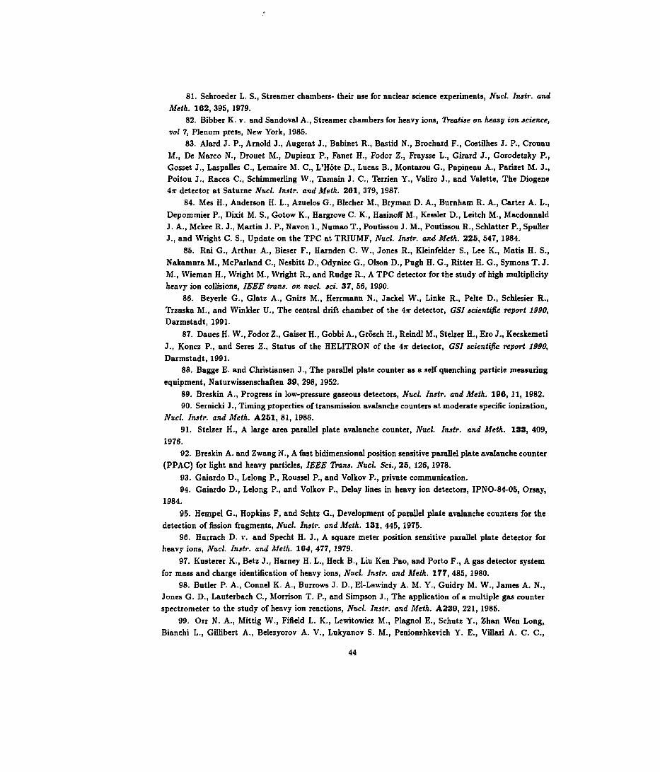
81. Schroeder L. S., Streamer chambers- their use for nuclear science experiments, Nucl. Instr. andMeth. 162, 395, 1979.
82. Bibber K. v. and Sandoval A., Streamer chambers for heavy ions, Treatise on heavy ion science,vol 7, Plenum press, New York, 1985.
83. Alard J. P., Arnold J., Augerat J., Babinet R., Bastid N., Brochard F., Costilhes J. P., CrouauM., De Marco N-, Drouet M., Dupieux P., Fanet H., Fodor Z., Fraysse L., Girard J., Gorodetzky P.,Gosset J., Laspalles C., Lemaire M. C., L'Hôte D., Lucas B., Montarou G., Papineau A., Parizet M. J.,Poitou J., Racca C., Schimmerling W., Tamain J. C., Terrien Y., Valiro J., and Valette, The Diogene4ir detector at Saturne Nucl. Instr. and Meth. 261, 379, 1987.
84. Mes H., Anderson H. L., Azuelos G., Blecher M., Bryman D. A., Burnham R. A., Gaiter A. L.,Depommier P., Dixit M. S., Gotow K., Hargrove C. K., Hasinoff M., Kessler D., Leitch M., MacdonnaldJ. A., Mckee R. J., Martin J. P., Navon L, Numao T., Poutissou J. M., Poutissou R., Schlatter P., SpullerJ., and Wright C. S., Update on the TPC at TRIUMF, Nucl. Instr. and Meth. 225, 547, 1984.
85. Rai G., Arthur A., Bieser F., Harnden C. W., Jones R., Kleinfelder S., Lee K., Mat» H. S.,Nakamura M., McParland C., Nesbitt D., Odyniec G., Olson D., Pugh H. G., Hitter H. G., Symons T. J.M., Wieman H., Wright M., Wright R., and Rudge R., A TPC detector for the study of high multiplicityheavy ion collisions, IEEE trans, on nucl. id. 37, 56, 1990.
86. Beyerle G., Glatz A., Gnirs M., Herrmann N., Jackel W., Linke R., Pelte D., Schlesier R.,Trzaska M., and Winkler U., The central drift chamber of the 4* detector, GSI scientific report 1990,Darmstadt, 1991.
87. Daues H. W., Fodor Z., Gaiser H., Gobbi A., Grosch H., Reindl M., Stelzer H-, Ero J., KecskemetiJ., Koncz P., and Seres Z., Status of the HELITRON of the 4ir detector, GSI scientific report 1990,Darmstadt, 1991.
88. Bagge E. and Christiansen J., The parallel plate counter as a self quenching particle measuringequipment, Naturwissenschaften 30, 298, 1952.
89. Breskin A., Progress in low-pressure gaseous detectors, Nucl. Instr. and Meth. 196, 11, 1982.90. Sernicki J., Timing properties of transmission avalanche counters at moderate spécifie ionization,
Nucl. Instr. and Meth. A251, 81, 1986.91. Stelzer H., A large area parallel plate avalanche counter, Nucl. Instr. and Meth. 133, 409,
1976.92. Breskin A. and Zwang N., A fast bidimensional position sensitive parallel plate avalanche counter
(PPAC) for light and heavy particles, IEEE Trans. Nucl. Sd., 25, 126, 1978.93. Gaiardo D., Lelong P., Roussel P., and Volkov P., private communication.94. Gaiardo D., Lelong P., and Volkov P., Delay Unes in heavy ion detectors, IPNO-84-05, Orsay,
1984.95. Hempel G., Hopkins F1 and Schtz G., Development of parallel plate avalanche counters for the
detection of fission fragments, Nucl. Instr. and Meth. 131, 445, 1975.96. Harrach D. v. and Specht H. J., A square meter position sensitive parallel plate detector for
heavy ions, Nucl. Instr. and Meth. 184, 477, 1979.97. Kusterer K., Betz J., Harney H. L., Heck B., Liu Ken Pao, and Porto F., A gas detector system
for mass and charge identification of heavy ions, Nucl. Instr. and Meth. 177, 485, 1980.98. Butler P. A., Connel K. A., Burrows J. D., El-Lawindy A. M. Y., Guidry M. W., James A. N.,
Jones G. D., Lauterbach C., Morrison T. P., and Simpson J., The application of a multiple gas counterspectrometer to the study of heavy ion reactions, Nucl. Instr. and Meth. A239, 221, 1985.
99. Orr N. A., Mittig W., Fifield L. K., Lewitowicz M., Plagnol E., Schutz Y., Zhan Wen Long,Bianchi L., Gillibert A., Belezyorov A. V., Lukyanov S. M., Penionzhkevich Y. E., Villari A. C. C.,
44

Cunsolo A., Foti A., Audi G., Stéphan C., and Tassan-Got L., New mass measurements of neutron richnuclei near N = 20, Phys. Lett. B258, 29, 1991.
100. Bieskin A., A subnanosecond low pressure MWPC for heavily ionizing particles, Nticl. Instr.and Meth. 141, 505, 1977.
101. Binon F., Bobyi V. V., Duteil P., Gouanete M., Hugon L., Spighel M., and Stioot J. P., Lowpressure multiwire proportional chambers with high time resolution fox stiongly ionizing particles, Nud.Instr. and Meth. 94, 27, 1971.
102. Bieskin A., Chechik R., and Zwang N., Heavy ion timing with very low pressure MWPCs,Nucl. Instr. and Metk. 166, 125, 1979.
103. Golovatyuk V. M., Ivanov A. B., Nikitin V. A., Peshekhonov V. D., and Zanevsky Yu. V., Alow pressure proportional chamber with a high space resolution,JVuc/. Instr. and Meth. 145, 437, 1977.
104. Charpak G., Will gaseous detectors become routine tools in biology and medicine? Nucl. Instr.
and Meth. A283, 371, 1989.105. Stelzer H., Multiwire chambers with a two-stage gas amplification, Nucl. Instr. and Meth.
A310, 103, 1991.106. Izycki M., Martin M., Rosselet L., and Solomey N., A large multistep avalanche chamber:
description and performance, Nucl. Instr. and Meth. A310, 98, 1991.
107. Breskin A., Chechik R., Fraenkel Z., Jacobs P., Tserruya I., and Zwang N., Low pressuremultistep detector for very low energy heavy ions, Nucl. Instr. and Meth. 221, 363, 1984.
108. Angelini F., Bellazini R., Brez A., Massai M. M., Spandre G., Torquati M. R., Bouclier R.,
Gaudens J., and Sauli F., The microstrip gas chamber, Nucl. Phys. 23A, 254, 1991.109. Oed A., Position sensitive detector with microstrip anode for electron multiplication with gases,
Nucl. Instr. Meth. A263, 351, 1988.
110. Bouclier R., Florent J. J., Gaudaen J., Millon G., Pasta A., Ropelewski L., Sauli F., andShekhtman L. I., High flux operation of microstrip gas chambers on glass and plastic supports, Nucl.Instr. Metk. A323, 240, 1992.
111. Barasch E. F., Bowcock T. J. V., DemroffH. P., Elliot S. M., Howe M. R., Lee B., Macumdar T.
K., Mclntyre P. M., Pang Y., Smith D. D., Wahl J., Wu Y., Yue W. K., Gaedke R. M., and VanstraelenG., Gas microstrip chambers, Nucl. Instr. Meth. A315, 170, 1992.
112. Angelini F., Bellazini R., Brez A., Decarolis G., Magazzu C., Massai M. M., Spandre G.,and Torquati M. R., Results from the first use of microstrip gas chambers in a high energy physicsexperiment, Nucl. Instr. Meth. A315, 21, 1992.
113. Angelini F., Bellazini R., Bosisio L., Brez A., Massai M. M., Spandre G., and Torquati M. R.,A microstrip gas chamber on a silicon substrate, Nucl. Instr. Meth. A314, 450, 1992.
114. Biagi S. F., Jackson J. N., Jones T. J., and Taylor S., Initial investigations of the performanceof a microstrip gas avalanche chamber fabricated on a thin silicon dioxide substrate, Nucl. Instr. Meth.A323, 258, 1992.
115. Nagae T., Tanimori T., Kobayashi T., and Miyagi T., Development of microstrip gas chamberswith multi-chip technology, Nucl. Instr. Meth. A323, 236, 1992.
116. Oed A., Geltenbort P., and Budtz-Jorgensen C., Substratum and layout parameters for mi-crostrip anodes in gas detectors, Nucl. Instr. Meth. A310, 95, 1991.
117. Budtz-Jorgensen C., Bahnsen A., Olesen C., Madsen M. M., Jonasson P., Schnopper H. W.,and Oed A., microstrip proportional counters for X-ray astronomy, Nucl. Instr. Meth. A310, 82, 1991.
118. Hartjes F., Hendriksen B., Schmitz J., SchvJlenburg H., and Udo F., Operation of the microstripgas detector, Nucl. Instr. Meth. A310, 88, 1991.
45

119. Angelini F., Bellazini R., Brez A., Massai M. M., Spandre G., and Toiquati M. R., A microstripgas avalanche chambet with two-dimensional readout, Nucï. Instr. Meth. A283, 755, 1989.
120. Barbosa A. F., Riekel C., and Wattecamps P., Two-dimentional X-ray detector based onmicrostrip and multiwire de.ign, Nucl. Instr. Meth. A323, 247, 1992.
121. Angelini F., Bellazini R., Bosisio L., Brez A., Massai M. M., Perret A., Spandre G., andTorquati M. R., A microstrip gas chamber with true two-dimensional and pixel readout, Nucl. Instr.Meth. A323, 229, 1992.
122. Richter J., Large size microstrip particle detectors, Nucl. Instr. Meth. A323, 263, 1992.123. Proceeding of the Sixth International wire chamber conference, Vienna, 1992. Nucl. Instr.
Meth. A323, 1992.
46