i progress report - dtic · sixth quarterly progress report october 1, 1963 - december 31, 1963....
TRANSCRIPT

I PROGRESS REPORT
._J
I SIXTH QUARTERJANUARY 1964
ELECTROLYTIC NIOBIUMAND
7,1IOBIUM ALLOY CAPACITORS
Reproduced FromBest Available Copy
UNION CARBIDE CORPORATIONLINDE DIVISIONKEMET DEPARTMENT

NOTICE: When government or other drawings, speci-fications or other data are used for any purposeother than in connection with a definitely relatedgovernment procurement operation, the U. S.Government thereby incurs no responsibility, nor anyobligation whatsoever; and the fact that the Govern-ment may have formulated, furnished, or in any waysupplied the said drawings, specifications, or otherdata is not to be regarded by implication or other-wise as in any manner licensing the holder or anyother person or corporation, or conveying any rightsor permission to manufacture, use or sell anypatented invention that may in any way be relatedthereto.

RESEARCH AND DEVELOPMENT WORK
ON ELECTROLYTIC NIOBIUM AND NIOBIUM ALLOY CAPACITORS
OF WET AND SOLID TYPES
BUREAU OF SHIPS CONTRACT NObsr-87478
SIXTH QUARTERLY PROGRESS REPORT
OCTOBER 1, 1963 - DECEMBER 31, 1963

ELECTROLYTIC N7IOBI0 AND NIOBIUM ALLOY CAPACTTORS
OF WET A1D SOLID TYPES
BUREAU OF S!!IPS CODE 691A2
SUBJECT:
Bureau of Ships Contract NObsr-87478Quarterly Research and Development Report, October 1, 1963 - December 31, 1963,and Final Engineering Report.
REFERENCE
Project Serial No. SR-0080302 ST 9600
PROGRAM OBJECTIVES
The development of 35, 50 and 100 volt niobium electrolytic capacitors ofhighest possible capacitance values, capable of full voltage operation at85C and with design objectives as listed in Military Specification MIL-C.26655for:
(1) electrical parameters,
(2) environmental characteristics,
(3) spatial configuration and dimensions,
(4) operating temperature range (-65*C to +85°C).
Report written by: Approved by:
F. E. Cariou J. S. WAgEner, ManagerProject Leader, Niobium R & D Research and Development
Union Carbide CorporationLinde Division, Kemet Department
Cleveland, Ohio

-Section I Sixth Quarterly Report L
Section 2 Technical Summary of the Program 13
Section 3 General Conclusions 20
Table i Physical Parameters for Agglomerated Anodes
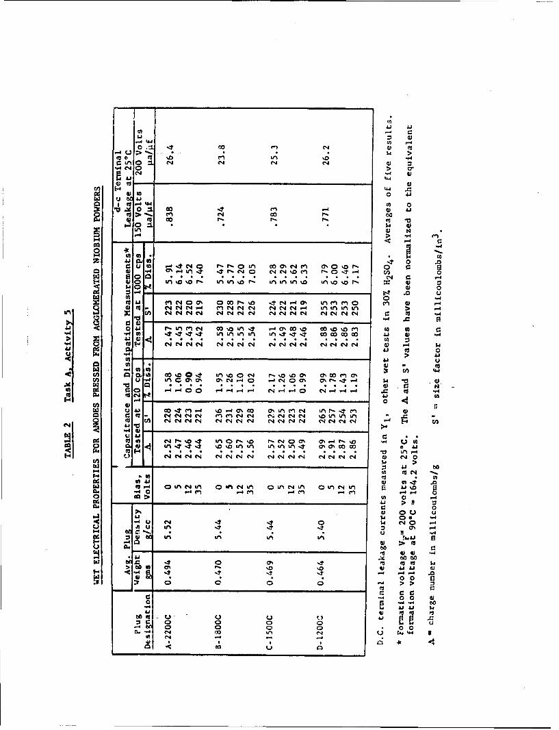
Table 2 Wet Electrical Properties for Anodes Pressedfrom Agglomerated Niobium Powders
Table 3 Porosimeter Results for Anodes Pressed fromAgglomerated Niobium Powders
Table 4A Process Details for Chemical Impregnation ofNiobium Capacitors, and Preliminary ElectricalResults
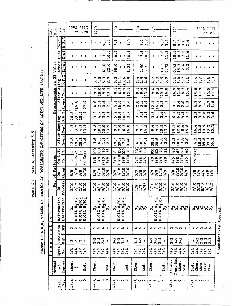
Table 4B Change of L, C, D, Values of ChemicallyImpregnated Capacitors on Aging and LifeTesting
Table 5 Niobium and Niobium-Tantalum Alloy PorousAnode Capacitor Batches, of Wet and Solid-Electrolyte Types, Submitted to the Bureauof Ships
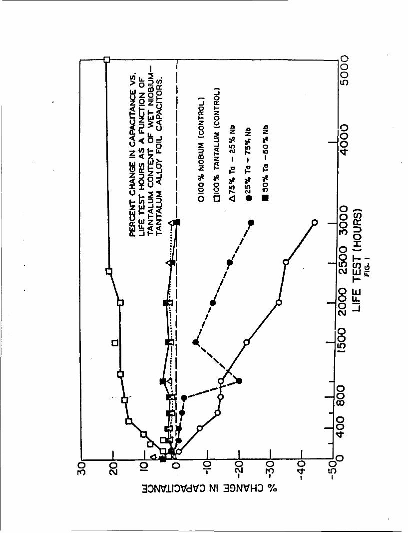
Figure 1 Percent Change in Capacitance vs. Life TestHours as a Function of Tantalum Content ofWet Niobium-Tantalum Alloy Foil Capacitors
Figure 2 Percent Change in Dissipation Factor vs. LifeTest Hours as Function of Ta Content of WetNb-Ta Alloy Foil Capacitors
Figure 3A Percent Change in Capacitance vs. Life TestHours for Various Types of Niobium Wet FoilCapacitors
Figure 3B Percent Change in Dissipation Factor vs. LifeTest Hours for Various Types of Niobium WetFoil Capacitors

SECTION T STXTH QUAPTERLY -'POPT
Task A - Work on Niobium and Niobium. Alloy Sintered Anode Capacitors ofWet and Solid Electrolyte Types
SUMMARY OF PROGRESS
Activity 5 - Determination of Optimum Processing Conditions for NiobiumPorous Anode Solid Electrolyte Capacitors
A. Objective
The object of this work is to determine the best processing methodsfor the preparation of niobium porous anode solid electrolyte capacitorsup to the canning stage. Parameters to be studied in this phase includeoptimum particle shape and size distribution, green density of anodes,sintering conditions, .chemical etching and. reformation-impregnationconditions.
B. Results of Recent Studies
(a) Sub-Activity 5.3 - Determination of Optimum Particle Size Distribu-tion for Niobium Powders Used in Pressing Capacitor Anodes
Powder Agglomeration Studies
In previous reports, some evidence was described indicating thatincreased capacitance (as measured by two parameters, charge numberA and size factor S) is obtainable by use of progressively smallerniobium powder particle sizes to press anodes, until a maximum sizefactor is reached at a geometric mean size of ten microns. However,a rapid increase in dissipation factor at 1000 cps was also foundto occur with decreasing particle size.
An attempt has been made to achieve the increased size factorwithout the concomitant rise in dissipation factor, by agglomerationof fine powders. It was hoped in this way to obtain a powder consistingof relatively coarse clinker-like particles with holes in them, andwith pressing characteristics that would result in anodes with a large,relatively open, internal pore surface area.
Rectangular slabs, pressed from fine -400 mesh niobium powders,were agglomerated by vacuum sintering at a series of temperaturesranging from 12006C to 2200*C. The sintered compacts were reducedto relatively coarse -170/+325 mesh powders (88 - 44 microns), andpressed into 0.160" diameter x 0.300" long anodes which were thensintered at 2100"C. Small samples of each powder were also examined%t different Magnifications in a metallograph, in order to detectpossible modifications in particle structure. No striking differ-ences were observed in the structures of powderq processed from thes!abs agglomerated at differen•t temperatures.

The processing details and results of wet electrical and porosi-
meter evaluations are given in Tables 1, 2 and 3. On the basisof wet test measurements, no improvement in size factor or dissi-pation factor was achieved over those obtained with the standardpowder blends described in previous reports. In general, the2200©C agglomeration yields the poorest results, while the 1200"Cagglomeration provides anodes with a somewhat higher size factor.In addition, the porosimeter evaluation of Table 3 suggestr thatthe relatively large pore sizes obtained by agglomeration at thislow temperature might lead to lower dissipation factors incompleted solid capacitors. Although this possibility shouldeventually be followed up, no further work has been done to date.
(b) Sub-Activity 5.5 - Determination of Optimum Impregnation andReformntion Methods
(I) Chemical Impregnation of Porous Anodes with MnO2
Previous studies of thermal damage of the Nb20 5 dielectriclayer incurred during conversion of Mn(N0 3 ) 2 to Mn0 2 , bypyrolysis at temperatures in excess of 250 C, indicated thatsome alleviation of the problem would result from use of achemical impregnation process requiring a maximum curingtemperature of about 200*C. Of the many possible chemicalreactions available for producing MnO2 at relatively low temper-atures, preliminary experiments indicated that the oxidation-reduction between permanganate and manganous ions offered thegreatest promise of yielding an MnO2 impregnant coating withelectrical characteristics at least as good as those providedby the conventional thermal conversion of Mn(N0 3 ) 2 .
Niobium powder from Material Lot 402 (see Table 5 of FifthQuarterly Report for description) was selected for this inves-tigation. After water sedimentation treatment to remove powderparticles of less than one micron diameter, two powder blendswere prepared at different times, both consisting of 25%-200/+325 and 757 -325 mesh size particles. Capacitor anodesof 0.160" diameter and 0.300" length were pressed to a greendensity of 5.2 gnms/cc and sintered at 2100C for thirty minuteaein a high vacuum furnace. After cooling, the vacuum chamberwas filled with argon gas and the sintered anodes removed dndstored in demineralized water in closed polyethylene corcainers.
Capacitor anodes were formed to 200 volts for four hours at acurrent density of 25 mam/pgm in Y1 electrolyte, which was main-tained at 25*C by means of a water-dry ice cooling bath.
After washing, formed anodes were impregnated with MnO 2 , eitherby the standard pyrolytic method [Mn(N0 3 ) 2 solution at 50C witha specific gravity of 1.65 at 16 C, pyrolysis temperature 275"C,standard 4/4 dip-reformntion sequence] or by the chemical impreg.nation method described as follows!

(a) dipped into sodiun permanganate solution and dried at 200CC,
(b) dipped into rianganous nitrate solation and dried at 200 0 C,
(c) steps (a) and (b) repeated the desired number of times,
(d) after the last dipping cycle, anodes dipped once more intomanganous nitrate solution and dried at 200*C.
(e) washed for one hoir in three changes of boiling deminera-lized water,
(f) heated for thirty minutes at 200"C,
(g) reformed in the standard manner, washed and impregnatedagain as in steps (a) through (f),
(h) reformed a second time in the standard manner.
The concentration of solutions used in this process were:
(a) 12.4 grams of NaMnO 4 . 3H2 0 per 100 rl of solution or per200 ml of solution,as noted in Table 4,
(b) 147 grams of Mn(NO3 ) 2 . 6H 2 0 per 100 ml of solution.
The following variables in process parameters were investigated:
(1) dip-reformation sequences of 3/2 (i.e., 3 dips, firstreformation, 2 dips, second reformation) 4/3, and 4/4,
(2) different dipping times in both the NaMnO4 and Mn(N0 3 ) 2
solutions,
(3) different drying times at 200 0 C,
(4) two different concentrations of NaMnO 4 solution,
(5) standard 0.01% H3 P04 reformation electrolyte versus specialreformation electrolyte 02, using the standard step-reforma-tion process with first and second reformation voltages of70 and 65 volts respectively,
(6) two different stntered anode batches,
(7) a combination of the standard and chemical impregnationprocesses.
Conclusions
(l) The processing details and preliminary electricnl evaluation for cnpac-itors made during this investigation are summarized in Table 4 A, whilethe life test data are given in Table 4B. In all tests made, the bestelectrical results wvre obtained with the control batches, for whichthe standard pyrolytic conversioa process wns used.

For example, the capacitnnce of chenically-impregnated units isconsiderably lower, the dissipation factor higher, and the DC elec-
trical leakage and failure rates are inferior, indicating poor pene-tration and incomplete conversion of MnO 2 in anode pores.
(2) The effort of the impregnation-conversion technique overrides that ofthe reformation electrolyte used. Thus chemically impregnated capac-itors display a higher failure rate than do capacitors impregnated bythe standard method, even when the special 02 reformation electrolyteis used for the former units.
(3) The results obtained with chemical impregnation are strongly dependenton all processing parameters including solution concentrations, dipcycle and time, and also on the physical characteristics (e.g., poresize and distribution) of the anodes. It is po...sible that a dryingtemperature higher than 200*C would provide better results - howeverthe anticipated lower treatment temperature was the main reason forinterest in chemical impregnation methods.
Since it is believed that more promising methods arc known for circum-venting or eliminating the effects of thermal damage during MnO2 impreg-nation of anodes than are offered by such chemical i£npregnation processes,further work is considered unwarranted.
(2) Further Studies of Reformation Electrolyte 01
In the Fifth Quarterly Report, the results of some experimentswith an improved zeformation electrolyte 02 were described. Sincethe dissipation factor of units made using this electrolyte withstandard reformation voltages (70/65 volts for 35 volt rated solidunits) were higher than for capacitors reformed in the standard0.01% H3 P0 4 electrolyte, further investigations of the optimumreformation voltage for 02 were undertaken, as well as use of 02in combination with several variations in the impregnation technique.
Since the results were mainly negative, they will not be reported indetail. At all reformation voltages listed (which ranged from 40to 80 volts in 5 volt increments) for 35 volt rated completed solidunits, the dissipation factor was somewhat higher than when astandard aqueous reformation electrolyte was employed. Moreover,the best reformation voltage, from the standpoint of DC leakagecurrent and 85*C, 1000 hour life test reliability, was approximatelythe iame (70/65 volts for 35 volt units) as for conventional reforma-tion electrolytes. Modification of the MnO 2 impregnation techniquedid not eliminate the dissipation factor increase, which appears tobe characteristic of reformation in electrolyte 02.
Further studies of this electrolyte are wnrranted, since the improve.ment in electrical performance on life test was again reproduced,and since the cause of the dissipation factor problem is believed tobe known.
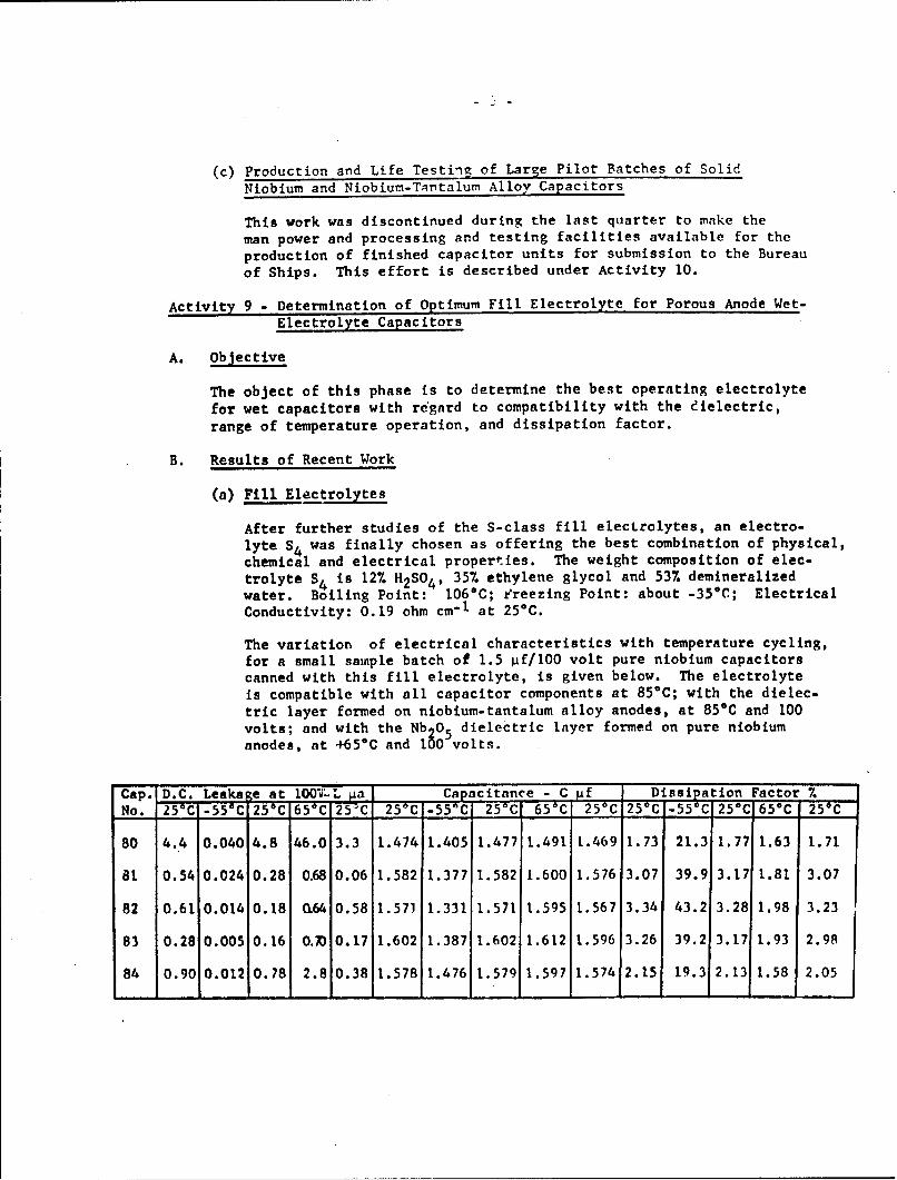
(c) Production and Life Testing of Large Pilot Batches of Solid
Niobium and Niobium-Tantalum Alloy Capacitors
This work was discontinued during the last quarter to make the
man power and processing and testing facilities available for the
production of finished capacitor units for submission to the Bureauof Ships. This effort is described under Activity 10.
Activity 9 - Determination of Optimum Fill Electrolyte for Porous Anode Wet-
Electrolyte Capacitors
A. Objective
The object of this phase is to determine the best operating electrolyte
for wet capacitors with regard to compatibility with the dielectric,
range of temperature operation, and dissipation factor.
B. Results of Recent Work
(a) Fill Electrolytes
After further studies of the S-class fill electrolytes, an electro-
lyte S 4 was finally chosen as offering the best combination of physical,
chemical and electrical properties. The weight composition of elec-
trolyte S 4 is 12% H2 SO 4 , 35% ethylene glycol and 537 demineralizedwater. Boiling Point: 106°C; freezing Point: about -35*C; Electrical
Conductivity: 0.19 ohm cm"I at 254C.
The variation of electrical characteristics with temperature cycling,
for a small sample batch of 1.5 pf/100 volt pure niobium capacitors
canned with this fill electrolyte, is given below. The electrolyteis compatible with all capacitor components at 85°C; with the dielec-
tric layer formed on niobium-tantalum alloy anodes, at 85*C and 100
volts; and with the Nb 05 dielectric layer formed on pure niobium
anodes, at +65*C and 100 volts.
Cap. D.C. Leakage at 100'""La Capacitance - C pf Dissipation Factor %
No. 25°C -556C 25*C 650 C125'C 25*C -55"C 250C 65 0 C 25*C 25 C -55 C'250 C 65*C 25*C
80 4.4 0.040 4.8 46.0 3.3 1.474 1.405 1.477 1.491 1.469 1.73 21.3 1.77 1.63 1.71
81 0.54 0.024 0.28 0.68 0.06 1.582 1.377 1.582 1.600 1.576 3.07 39.9 3.17 1.81 3.07
82 0.61 0.014 0.18 0.64 0.58 1.571 1.331 1.571 1.595 1.567 3.34 43.2 3.28 1.98 3.23
83 0.28 0.005 0.16 O.M 0.17 1.602 1.387 1.602 1.612 1.596 3.26 39.2 3.17 1.93 2.98
84 0.90 0.012 0.78 2.8 0.38 1.578 1.476 1.579 1.597 1.574 2.15 19.3 2.13 1.58 2.05

(b) Other Process Investigations
(I) A considerable decrease in electrical leakage c'ircents occursafter aging of capacitors at 120 volts and 25*C for 100 hours.This was found to be accompanipd by a small decrease incapacitance and dissipation factor. The effect is due mairnlyto evolution of gas at defects in the dielectric layer, whichare eventually plugged up by the gas bubbles. Howev-r, thisgas generation results in e%cessive internal pressure buildupduring subsequent life testing and eventually causes capacitorfailures.
(2) Reanodization of niobium anodes in hot fill electrolyte beforecanning did not improve the subsequent life test pertormance.
(3) Life testing of pure niobium capacitors preheated to +850Cbefore final sealing did not reveal any beneficial resultsfrom this treatment.
(4) Longer formation times (17 hours instead of 4 hours) for niobium
anodes decreased the initial value of DC electrical leakage butdid not eliminate the aging effect.
(5) Aging of niobium anodes at 120 volts and 25*C or 85*C, for upto 150 hours in an open tank of fill electrolyte before canning,did not improve the subsequent electrical performance.
(6) Aging of anodes in the cans before final sealing increased thedissipation factor without affecting the electrical leakage.
(7) Anodes removed from capacitors which had failed on life test,when recanned using new components, displayed the same agingeffect as before, although the initial leakages after recanningwere considerably lower. After about 100 hours of life testingboth original and recAnned capacitors showed approximately thesame leakage current levels and susceptibility to failure.This effect is illustrated in the following table, for a smallsample of 22 gf/100 volt capacitors.
Leakage Current (pa)
After 115 Hrs. LifeBefore Aging After Aging Test at 85*C
Capacitor Original Original OriginalNumber Canning Recanned Canning Recanned Canning Recanned
1 7.5 1.62 2.4 0.50 0.47 0.45
2 8.9 1.25 2.4 0.28 0.31 0.39
3 7.5 0.58 2.4 0.18 0.25 0.25

(c) Pilot Batches of Capa:itcrs
Pilot production of larger (60-75 units) batches of pure niobiumand niobium-tantalum alloy capacitors was continued during thelast quarter. Life test results have verified a previous conclu-sion that the present technology will not produce pure niobiumwet-electrolyte 100 volt units capable of continuous long-termservice at +85'C. All such capacitors produced to date, even
those employing fill electrolyte S4 , have failed before 800 hoursof life test have elapsed. This particular combination of voltageand temperature appears to result in either electrochemical attackor in crystallization of the amorphous oxide layer, with even thebest fill electrolytes found to date. Thus the electrical leakagegradually increases with time on life test until the capacitorseventually burst due to internal gas pressure buildup.
On the other hand, it has been found possible to make successfullythe following capacitor types:
(1) 1.5 pf/100 volt and 20 pf/100 volt units from pure niobiumanodes, capable of operation at +65*C.
(2) 2.5 4f/1OO volt and 22 if/0OO volt units from niobium - 81%tantalum alloy anodes, capable of operation at +850C. Unitsof these types have survived 1000 hours (in some cases up to3500 hours) of life testing with little or no degradation inelectrical performance.
It is believed that equally good capacitors could be made fromniobium-tantalum alloy materials containing 50% tantalum or lower.Unfortunately, the supply of lower tantalum content alloy powders-(25% tantalum and 50% tantalum) was exhausted during pilot produc-tion of solid electrolytic capacitors and in studies of optimumpowder particle size distribution for wet-electrolyte capacitors.
'Acti .ty 10 - Production and Testing of Pure Niobium and Niobium Alloy PorousAnode Capacitors of Wet and Solid-Electrolyte Types
Sub-Activities 10.1 and 10.3 - Solid Niobium and Niobium Alloy Capacitors
Eight batches of niobium and niobium-tantalum alloy capacitors consistingof twenty-four units per batch, were made and tested for delivery to theBureau of Ships in Washington, D. C. in partial fulfillment of the terms ofthe contract.
All batches were subjected to 1000 hours life testing at 85*C and ratedvoltage. The average electriccl characteristics of each capacitor type afterlife testing are sumnarized in Table 5. In addition, samples of these capac-itors, subjected to the following Quality Control Tests under specifiedconditions, were found to meet the pertinent Military Specifications MIL-C-26655 for solid tantalum capacitors:

1I) Shock testing
(2) Vibration testing
(3) Temperature stability testing (-55*C to +125°C)
(4) Surge voltage testing (85*C, 120% rated voltage, 125°C, 80% rated voltage)
(5) Temperature cycling (-55°C to +125*C)
(6) Humidity testing
Although the pure niobium and niobium alloy units withstood the short termtests at 125*C, they cannot be recommended for extended use at this temper-ature, even with an appropriate voltage derating. The maximum allowableoperational temperature for long-term performance stability is +85*C.
Sub-Activities 10.2 and 10.4 - Wet Niobium and Niobium Alloy Capacitors
Four batches of niobium and niobium-tantalum alloy capacitors, consistingof twenty-four units per batch, were made and tested for delivery to theBureau of Ships in Washington, D. C. in partial fulfillmenL of the terms ofthe contract.
All batches were subjected to at least 250 hours of life testing at 100 voltsand rated temperature (either +65*C or +85°C). The average electrical charac-teristics of each capacitor type, after testing, are summarized in Table 5.Other lots of the same capacitor types are continuing on life test underspecified conditions - in the case of 100 volt, 65 0 C units, the electricalcharacteristics of the best lots are still stable after more than 3000 hourson test.
In addition, samples of these capacitors, subjected to the following QualityControl Tests under specified conditions, were found to meet the pertinentMilito- Specifications of MIL-C3965 for wet tantalum capacitors.
(1) Shock testing
(2) Vibration testing
(3) Temperature stability testing (-55'C to +65*C).
(4) Terminal strength testing
(5) Surge voltage testing
(6) Barometric pressure testing.
The maximum recominended operating temperature for the 100 volt pure niobiumwet-electrolyte units is +65C, while for the 100 volt niobium-tantalum alloyunits it is +85*C.
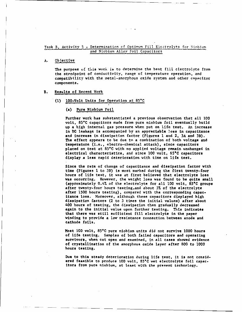
Task B, Activity 5 - Determination of Optirum Fill Eiectrolyte for Niobium
and Niobium Alloy Foil Capacitors
A. Objective
The purpose of this work ib to determine the best fill electrolyte fromthe stpndpoint of conductivity, range of temperature operation, andcompatibility with the metal-amorphous oxide system and other capacitorcomponents.
B. Results of Recent Work
(1) 100-Volt Units for Operation at 85*C
(a) Pure Niobium Foil
Further work has substantiated a previous observation that all 100volt, 85*C capqcitors made from pure niobium foil eventually buildup a high internal gas pressure when put on life test. An increasein DC leakage is accompanied by an appreciable loss in capacitanceand increase in dissipation factor (Figures 1 and 2, 3A and 3B).The effect appears to be due to a combination of both voltage andtemperature (i.e., electro-chemical attack), since capacitorsplaced on test at 85*C with no applied voltage remain unchanged inelectrical characteristics, and since 100 volt, 65*C capacitorsdisplay a less rapid deterioration with time on life test.
Since the rate of change of capacitance and dissipation factor withtime (Figures 1 to 3B) is most marked during the first twenty-fourhours of life test, it was at first believed that electrolyte losswas occurring. However, the weight loss was found to be quite small(approximately 0.4% of the electrolyte for all 100 volt, 85*C groupsafter twenty-four hours testing,and about 37 of the electrolyteafter 1500 hours testing), compared with the corresponding capac-itance loss. Moreover, although these capacitors displayed highdissipation factors (2 to 3 times the initial values) after about400 hours of testing, the dissipation then gradually decreasedagain to the initial value upon further testing. This indicatesthat there was still sufficient fill electrolyte in the paperwinding to provide a low resistance connection between anode andcathode foils.
Most 100 volt, 85*C pure niobium units did not survive 1000 hoursof life testing. Samples of both failed capacitors and operatingsurvivors, when cut open and examined, in all cases showed evidenceof crystallization of the amorphous oxide layer after 800 to 1000hours testing.
Due to this steady deterioration during life test, it is not consid-ered feasible to produce 100 volt, 85*C wet electrolyte foil capac-itors from pure niobium, at least with the present technology.

(b) Niobium-Tantaiurn Ali-; Feil
Further work has been carried out on 100 volt, 85*C unitsprocessed from niobiun-tantalum alloys containing 75%, 50%and 257. niobium by weight, in an effort to identify the bestalloy for preparation of capacitors to be submitted to theBureau of Ships. In the following table, the electricalcharacteristics of these capacitors are compared after 3000hours of life testing. in addition, Figures 1 and 2 illus-trate graphically the percentage change of capacitance anddissipation factor with test time for these alloy and pure
niobium units.
Measurements at 25*C, Rated Voltage
Capacitance pf Dissipation Factor %D.C. Leakage pa at 120 cycles at 20 cps
0 hours 3000 hours 0 hours 3000 hours 0 hours 3000 hours
75% Ta-25% Nb 4.1 0.18 5.58 5.64 1.9 1.8
50% Ta-50% Nb 3.8 0.22 5.70 5.62 1.7 2.0
25% Ta-75% Nb 6.3 2.7 5.98 4.61 1.7 3.3
100% Nb-Control 1.1 2.5 6.38 3.65 1.6 3.8
It is clear from the results that the capacitor qualitydecreases with increasing niobium content. Although the757 tantalum-25% niobium and the 507 tantalum-507 niobiumalloy units are still satisfactory after 3000 hours testing,it appears that there is a definite relationship betweenniobium content, electrical characteristics and time.
(2) 100 Volt Units for Operation at 65eC
Based on the experience with porous anode wet electrolyte units,it was thought that production of an acceptable !00 volt, 65C unitfrom pure niobium foil might be possible. Accordingly, two groupsof this capacitor type were made and put on life test. Thevariation of electrical characteristics with test time are outlinedin the table below.
Measurements at 25*C, 100 Volts
Dissipation Factor %Batch D. C. Leakage'- pa Capacitancepf at 120cps at 120 ps
No. O hrs. 600 hrs. 1500 hra. 0 hrs. 600 hrs. 1500 hrP. 0 hrs. 600 hrs. 1500 hrs.
1 12.3 1.59 3.3 6.11 5.69 5.47 2.0 5.4 7.0
2 5.2 0.42 1.8 5.50 5.53 5.44 1.7 2.7 4.2

From the results, it appears that the lowet test temperature merely
slows down the gradual degradation of electrical characteristics.
(3) 50 Volt Units for Operation at 85*C
Three groups of 50 volt, 85*C capacitors were processed from pureniobium foil, using different formation voltages and formationtechniques.
The first batch was anodized at 200 volts in a small formation tankand then split into two groups, one for operation at 50 volts, 85*Cand the other for 100 volts, 85*C operation. The results after1500 hours of life testing, suimmarized in the table below, are very
interesting.
Measurements At 25*C,.RAted Voltage
Capacitance, gf Diss. Factor %D.C. Leakage pa at 120 cps at 120cps Yield .
0 800 1500 0 800 1500 0 800 1500 0 800 1500Hrs. Hrs. Hrs. Hrs. Hrs. Hrs. Hrs. Hrs. His. Hrs. Hrs. Hrs.
850C,50 VoltOperation 9.0 0.14 0.17 7.90 8.01 8.26 1.9 1.5 1.6 100 100 100
85-C,100 Volt All All AllOperation 23.0 4.5 Failed 7.80 3.58 Failed 1.8 2.2 Failed 80 40 0
It is evident that there is a marked difference in the activityof the fill electrolyte when the operating voltage is decreasedfrom 100 to 50 volts at 85*C.
Two other groups of 50 volt, 85°C pure niobium foil capacitors wereprocessed using a large formation tank to improve the formationconditions. The only difference in these two foil gmups was thatone was formed to 150 volts and the other to 160 volts. The elec-trical characteristics of these capacitors are compared with thoseof similar capacitors formed to 200 volts.
Measurements at 25*C, 50 Volts
D.C. Leakage Capacitance Diss. Factor %Formation 4a f at 1 20 cps at 120 cpsVoltage 0 800 1500 0 800 1500 0 800 1500Volts Hrs. Hrs. Hrs. Hre. Hrs. Hrs. Hrs. Hrs. Hra.
150 1.4 0.13 0.09 9.6 10.3 10.3 2.0 1.7 1.6
160 0.70 0.10 - 9.9 9.5 - 2.0 1.4
200 9.0 0.13 0.17 7.9 8.1 8.2 1.9 1.5 1.6
, . _ _ __ _ _ _

- 12 -
The results indicate good stability in electrical properties for50 volt units, and little or no effect from the use of a lowerformation voltage. Moreover, no evidence has been found of thebuildup of internal gas pressure or crystallization of the dielec-tric layer, in some of these units which have been cut open forexamination.
(4) 75 Volt Units for Operation at 85*C
Because of the success achieved with the 50 volt, 85*C units, anattempt was made to produce a 75 volt, 85°C capacitor using pureniobium foil. Life test results on one group of there capacitorsindicated the same characteristic loss of capacitance and increasein dissipation factor as was encountered with the 100 volt, 85Cunits (see Figure 3A and 3B). Moreover, examination of one ofthese units after 800 hours of life testing disclosed signs ofserious pressure buildup and crystal lization of the dielectriclayer. In fact, there appears to be little difference in behaviorbetween 100 volt, 85*C capacitors and 75 volt, 85*C capacitors, sofar as rate of electrical degradation is concerned.
Task B, Activity 7 - Production and Testing of Pure Niobium and Niobium Alloy
Foil Capacitors of Wet Electrolyte Type
Sub-Activities 7.1 and 7.2
One batch of pure niobium foil capacitors and one batch of niobium-tantalumalloy foil capacitors, consisting of twenty-four units per batch, were madeand tested for del ivery to the Bureau of Ships in Washington D. C. inpartial fulfillment of the terms of the contract.
The capacitors have been subjected to at least 600 hours of life testing at85"C and rated voltage (50 and 100 volts). The average electrical character-istics after tosting are listed below.
Average Electrical CharacteristicsCapacitor at Rated Voltage,. 25'C
Batch Type Can D.C. Leakage Capacitance Diss. Factor=7.No. Description C pf/V volta Size Pa pf at 120 cps at 120 cps
Pure niobium foilwet electrolyte. 10/50 C3 0.13 9.96 1.73
Nb-50% Ta alloy foil2 wet electrolyte. 5.6/100 C3 0.088 5.63 2.48
SAmples of these capacitors, on life test for more than 2500 hours underspecified conditions, hAve shown no degradation in electrical performance.Other %nmples of theme capncitors, subjected to the following Quality Controltents under mpocified conditions, were found to meet the pertinent MilitarySpecificatInrr MTI.-C-3965 for tantnlum foil capneitort:

(1) Temperature stability testing(2) Vibration testing(3) Temperature and immersion cycling(4) Surge voltage.testing(5) Moisture resistance testing(6) Reduced pressure testing
The maximum recommended operating temperature for both capacitor batches, atrated voltage or lower, is +85*C.
SECTION 2 - TECHNICAL SUMMARY OF THE PROGRAM
Task A - Work on Niobium and Niobium Alloy Porous Anode Capacitors of Wetand Solid Types
Activity 1 - Trace Impurity Analyses of Niobium Materials Made by DifferentProcesses
Exhaustive trace impurity analyses were carried out on p,,re niobium materialsmade by three different processes - hydrogen reduction of pentachlorides,carbothermic reduction of oxides, and a proprietary process. Of the threematerials as received, the hydrogen-reduced niobium appeared to be the purest.
This analytical work,. in conjunction with subsequent electrical evaluation ofthe materials in the form of capacitor anodes, enabled a tentative purityspecification for capacitor-grade niobium powder to be written.
In this activity, development of improved analytical techniques was requiredto obtain adequate detection sensitivity for certain impurities, such as Zr,Ti, V, Sn, Al, Si, and Li.
The work is described in complete detail in Technical Report No. P-63-11, acop! of which will be furnished to the Bureau of Ships as part of the EngineeringSpecifications.
Activity 2 - Preparation of Niobium-Tantalum Alloy Powders
A vacuum sintering method of alloying tantalum and niobium powders wasdeveloped and used to make alloys containing 26.3, 51.1, 57.3, 80.8 and 100%by weight tantalum. The homogeneity was checked by metallographic and elec-tron microprobe techniques and found to be comparable with that of electron-beam melted samples. The purity of the materials was very high, although thenitrogen contents were somewhat greater than desired.
The work it described in detail in TechnicAl Report P-63-9, a copy of whichwill be furnished to the Bureau of Ships as part of the Engineering Specifica-tions.

Activity 3 - Optimum Conditions for Removal of Carbon frot Niobium
A vacuum prepurification heat treatment of niobium materials at 2100*C and2300*C and the effect of doping materials with oxygen by anodization, wereinvestigated, in an effort to reduce the levels of metallic (e.g. iron) andnon-metallic impurities (e.g. carbon) in capacitor-grade materials. Itwas found from analytical and electrical evaluations that such prefurnacingtreatment does not yield any advantage, provided a temperature of 2100*Cfor at least thirty minutes is used in sintering capacitor anodes. Anatomic ratio of 10 - 20 to 1 of oxygen to carbon is needed for removal ofcarbon to the 20 ppm level during sintering; on the other hand, excessiveoxygen levels in sintered anodes can also impair their performance. Mostmetallic impurities are readily removed to low levels by volatilizationduring sintering.
Activity 4 - Optimum AnoAzation Conditions for Niobium Anodes
Extensive studies were carried out to determine the best anodization condi-tions, formation electrolyte, time, temperature, current density, electro-lyte agitation and ratio of formation voltage to solid operating voltage.
A total of thirteen electrolytes were tested on the basis of terminal leakagecurrents, and breakdown voltages. The electrolyte conductivity, which wasstudied over a wide range for the better electrolytes, was found to exert amarked influence on the breakdown voltages of anodes (Figure 2, Third QuarterlyReport). A reliable well-defined correlation between wet test evaluations andsubsequent solid test electrical performance of anodes was not uncovered. Itwas found that a formation temperature of 25*C or lower must be used, in orderto form oxide films with the best possible dielectric properties, and thatformation times in excess of four hours do not improve solid test performanceof completed capacitors. Current density and electrolyte stirring are impor-tant mainly because of the effect on the electrolyte temperature in thevicinity of the anodes.
Activity 5 - Optimum Processing Conditions for Niobium Anode Solid Electrolyte
Capacitors
Detailed studies were made to optimize the following processing steps:
(I) Conversion of raw materials into capacitor-grade powder.
(2) Methods for sizing, blending and pressing of powders into anodes.
(3) Sintering conditions for anodes.
(4) Storage methods for sintered anodes.
(5) Pre-formation and post-formation chemical cleaning of anodes.
(6) PreheatinR and resnodization of formed anodes prior to pyrolysis.

15 -
(7) Semiconductor impregnation of formed anodes.
(8) Reformation of anodes.
(9) Carbon and silver coating and canning of impregnated anodes.
(10) Aging of canned capacitors.
Since these studies were discussed in some detail in the Quarterly Reports,only the more salient points will be mentioned here:
Powders
It was found to be essential to minimize pickup of oxygen and nitrogen duringpulverizing by conducting the milling operation in an argon atmosphere. Itis important to remove ultra fine particles (particle sizes less than onemicron) from size-reduced materials before blending them into capacitor-gradepowders. A simple method 6f effecting this removal, by a water sedimentationtechnique, was successful. The most suitable niobium particle size distribu-tion for pressing porous anodes (geometric mean size about 29 microns) isrelatively coarse compared with powder blends used for similar-sized tantalumanodes (geometric mean sizes down to 15 microns). Use of a parameter (geometricmean size), which typifies any powder blend by a single number measuring theaverage particle size, was found to be convenient.
Anodes
A minimum green density of about 5.0 gms/cc was found to be necessary to obtainniobium anodes of suitable mechanical strength and pore structure after sintering;pore diameters less than 1 or 2 microns are Undesirable since they tend to closeup during anodization and are then virtually impossible to impregnate with MnO 2 .A sintering temperature of 2100'C for thirty minutes was found to be necessaryto obtain anodes of satisfactory chemical purity. Placing of anodes in deminer-alized water in polyethylene containers immediately after sintering was found tobe tV- most satisfactory method of storage prior to anodization. Even in thiscase, it is important to utilize anodes as quickly as possible after sintering.If anodes are stored for prolonged periods of time before use, a pre-cleaningin AR.-grade acetone followed by thorough rinsing, before anodization, providesbetter finished capacitors. Preformation cleaning treatments in nitric acidwere found to offer no improvement in solid capacitor properties. Pre-etchingtreatments in bromine-methanol or hydrofluoric acid solutions were found todegrade the electrical performance of anodes, probably because of the diffi-culty of removing reaction products from the complex internal pore network.Similarly post-formation etching treatments, followed by reanodization, althoughapparently improving wet test properties, did not result in improvement ofsolid capacitor performance.
Impregnation of Anodes and Reformation
It was found to be important to keep the conversion tempernture below 280*Cduring pyrolysis of Mn(N0 3 ) 2 to form MnO 2 in niobium anode pores, In order tominimize thermil datAge.

16 -
Chemical impregnation techniques, for depositing MnO in anode pores and
requiring a maximum reaction temperature of 200*C, yielded capacitors with
much poorer electrical properties than units impregnated in the standardmanner. Other impregnation modifications tested did not substantiallyimprove capacitor performance.
A non-aqueous reformation electrolyte was developed which markedly reduced
the leakage currents and 85*C life test failure rates of canned capacitors.
Ag"ing
It is important to avoid a combination of voltage stress and thermal stressduring initial stages of aging. The canned units are therefore first agedat room temperature at a series of voltages ranging from rated voltage up toabout 1407 of rated voltage.
Activity 6 - Preparation of HLghly Purified Niobium Powders
About 2.5 pounds of ultra high purity niobium metal, in the form of roundels,were prepared using a specially developed ion-exchange pur4.fication method.The method is described in detail in Technical Report No. P-63-13, a copy ofwhich will be furnished to the Bureau of Ships as part of the EngineeringSpecifications. Although of much higher purity than other cap#citor-gradeniobium materials investigated, this material did not yield anodes withsuperior electrical properties.
High purity niobium microspheres were prepared by plasma arc melting ofniobium wire. Although this material, when made into a standard size distri-bution powder,provided anodes with acceptably low leakage currents on solidtest, the dissipation factors were high and the size factors inordinately low.
Activit" 7 - Optimum Anodization Conditions for Niobium Alloy Solid ElectrolyteCapacitors
The optimum anodization conditions for niobium-tantalum alloy anodes werefound to be the same as for pure niobium anodes. Most electrical properties(breakdown voltage, terminal leakage current, size factor) on wet test improvewith increasingtantalum content of the alloys; and this conclusion appears toapply also to electrical performance of completed solid units on life test at850C.
Activity 8 - Optimum Processing Conditions for Niobium-Alloy Solid ElectrolyteCapacitors
Insufficient alloy material was available to carry out a separate detailedstudy of all processing parameters. Procesting conditions developed for pureniobium anodes were found to be equally matisfaztory for the alloy materialsunder study.

17 -
Activity 9 - Optimum Fill Electrolyte for Porous Anode Wet Capacitors
Although a large number of fill electrolytes were tested, an electrolytecompatible with the Nb-Nb 2 0 5 system at 95*C and 100 volts and possessing satis-factory electrical conductivity over the temperature range from -550C to +85*Cwas not found. However, an electrolyte suitable for use in 100 volt niobium-tantalum alloy capacitors up to 85*C, and in 100 volt pure niobium capacitorsup to 65*C, was eventually developed after considerable effort.
Activity 10 - Production of Pure Niobium and Niobium Alloy Porous Anode Wet andSolid Electrolyte Capacitors for Delivery to the Bureau of Ships
After a period of pilot production and testing of various capacitor types,eight batches of solid niobium and niobium-tantalum alloy capacitors in A, B,C and D case sizes, and with 35 and 50 volt ratings, were made and subjectedto life testing and environmental testing. Having been found to meet MilitarySpecifications for similar tantalum capacitor units, these batches were sub-mitted to the Bureau of Ships in Washington, D. C. for evaluations, in quanti-ties of twenty-four units per batch.
After a similar pilot development effort, four batches of 100 volt wet niobiumand niobium-tantalum alloy capacitors in TI and T3 case sizes were made, tested,and submitted to the Bureau of Ships for evaluation.
The processing details for these capacitors are given in Kemet Technical ReportK-1963, a copy of which will be furnished to the Bureau of Ships as part of theengineering specifications.
Task B - Work on Niobium and Niobium-Alloy Foil Capacitors
Activity I - Preparation and Testing of Pure Niobium 0.010" Thick Sheet Madefrom Two Different Materials
Platco of pure niobium, made by electron beam purification and by a proprietaryprocess, were rolled into 0.010" thick sheet. Portions were then subjected todifferent metallurgical treatments as follows:
(1) strained sheet as rolled.
(2) stress-relieved foil.
(3) recrystallized foil or smallest grain size.
(4) recrystallized foil pack rolled between niobium cover plates.
Samples were analyzed for interstitial impurities, and test specimen sampleswere evaluated on wet test for breakdown voltage and terminal leakage current.In each case, the quality wan found to be comparable with that of commerciallyavailable niobium capacitor-grade foil.

-13 -
Activity 2 - Preparation and Testing of Five Different Niobium-Tantalum Alloevin the Form of 0.010" Thick Sheet
Alloy ingots containing 0, 25, 50, 75, and 100% by weight tantalum were prepnredby electron beam melting of suitable proportions of pure niobium and tantalummaterials. Pieces of the ingots were then rolled into 0.010" thick sheet and
recrystalli~ed. Electrical evaluation of test specimens of foil showed aprogressive improvement in quality with increasing tantalum content. This
observation was corroborated by subsequent life testing of completed capacitorunits made from 0.0005" thick foil, which indicated that even an alloy con-taining 50 percent tantalum by weight is inferior to pure tantalum material.
Activity 3 - Preparation and testing of Niobium-Platinum and Niobium-ZirconiumAlloys in the Form of 0.010" Thick Sheet
Alloys containing 0.1% by weight platinum and 1.0% by weight zirconium wereprepared by electron beam melting of pure constituent materials. Pieces ofalloy were then rolled into 0.010" thick sheet and recrystallized, while otherportions were rolled into unannealed 0.0005" thick foil. Since electricalevaluation of test specimens indicated that the niobium-pLatinum and niobium-zirconium alloys were inferior to the niobium-tantalum alloys described above,no further work was done on these alloy materials.
The preparation of the pure niobium and niobium alloy foil materials discussedunder Activities 1, 2, and 3 is fully described in Technical Report No. HS-l,
a copy of which will be furnished to the Bureau of Ships as part of the Engi-neering Specifications.
Activity 4 - Optimum Processing Conditions for Niobium and Niobium Alloy Foils
A superior formation electrolyte for niobium and niobium alloy foil materialswas developed, after testing of a large number of electrolytes. As in the caseof o- de formation on porous anodes, the electrolyte conductivity was found tohave a critical influence upon the breakdown and electrical quality of theanodic oxide layer formed on foil. The optimum electrolyte resistivity is muchhigher (approximately 3 x 10⁴ ohm cm) than for niobium porous anodes. Theoptimum formation temperature is O*C or lower, although 25*C formation willalso produce satisfactory dielectric films.
Vacuum prefurnacing of foil before anodization, although resulting in much bettersurface purification than can be accomplished by chemical etching techniques,is impractical for the rather long strips of foil used in finished capacitors.An etching solution was found which provides satisfactory surface cleaning priorto anodic oxide formation.
Activity 5 - tptimum Fill Electrolyte for Nioblum and Niobium-Alloy Foils
After ewtensive examination of varinus fill electrolytes, one was foutnd whichmakes possible the manufacture of 100 volt foil capacitors capable of operationup to 85'C, provided that a niobium-tantalum alloy material is used.

Although this same electrolyte is not suitable for use in a similar pureniobium foil capacitor, due to eventual crystallization of the Nb2 0 5 dielec-tric layer after approximately 1000 hours of life testing, it can be used tomake pure niobium units of 50 volts rating.
Activity 6 - Rolling of Selected Niobium and Niobium-Alloy Materials intoCapacitor Grade Foil
Portions of all pure niobium and niobium alloy materials, described under
Activities 1, 2 and 3, were converted into 0.0005" thick capacitor-grade foil.The foils were not annealed after final rolling, since it was found that suchtreatment had little or no effect on electrical characteristics, and increasedthe possibility of surface contamination of the foil.
Activity 7 - Production and Testing of Niobium and'Niobium Alloy Foil Capac-itors for Submission to the Bureau of Ships
After a period of experimental pilot production and testirg of large capacitorbatches, two batches consisting of 24 units each were mado and tested for
submission to the Bureau of Ships. One batch, made from a 50% niobium - 50%
tantalum alloy foil, is rated at 100 volts at a maximum operating temperatureof 85*C, while the other batch, made from pure niobium foil, is rated at 50 voltsat +850C.
The processing details for these capacitors are also given in Kemet TechnicalReport K-1963.
Task C - Fundamental Studies of Niobium and Tantalum Single Crystals and Foil
In the basic studies of anodic oxide films formed on niobium and tantalum, themain investigation was focused on high purity foil and single crystal specimens.
In the first phase, except for some exploratory and confirmatory experiments,anodizing conditions (electrolyte composition, current density and temperature)were kept constant. The progress of anodization was followed to breakdown of
the dielectric films by electron microscopy using carbon replicas or, in somecases, the isolated oxide films themselves. Minor defects in the amorphous
films on niobium foil and single crystals were noted at quite low voltages,
and their development into catastrophic ruptures with increasing voltage wasfollowed. In contrast, similar defects appeared with tantalum specimens only
at much higher voltages. Unique with the niobium specimens was the occurrenceof white powder spots in the anodic films upon breakdown - subsequent examina-tion by X-ray diffraction methods identified this material as a crystallineform of Nb,0 5 . Thermal oxidation experiments on niobium and tantalum anodizedfoils confirmed the greater susceptibility of amorphous Nb2 0 5 films to growth ofcrystallite areas, especially in the presence of surface contaminants such asfluorides. Further work should'be carried out to determine the origin andgrowth mechanism of the various types of film defects observed in these studies.

- 20 -
In a second phase, the influence of electrolyte composition and electrolytetemperature in suppressing the formation of defects in oxide films on foil,was studied-En some detail. This work has confirmed the important role ofelectrolyte selection in improving film quality, an observation hithertobased mainly on electrical measurements. Thus the superior electrical proper-ties of films formed with the best electrolyte waz shown to be due to a muchlower density of defects in the anodic film formed at a given voltage, andespecially to the absence of crystalline areas. The reasons for the vuperi-ority of one electrolyte over another are not fully understood at present.Similarly, an interesting difference in optimum formation conditions forniobium and tantalum, previously concluded from electrical evaluation data,was confirmed: for tantalum pentoxide films, the defect density tends todecrease with increasing formation temperature, over the range OC to 90*C,whereas for niobium pentoxide films, the converse is true.
In another study, it was found, somewhat surprisingly, that surface flaws insingle crystals (e.g. mechanical deformation, subgrain boundaries and preci-pitated carbide particles) apparently do not provide preferred nucleationsites for breakdown of the anodic films. Similarly the crystallographic orien-tation of the crystals appears to bear no relationship to the type or densityof defects. Finally, surface conditions of the crystals, as controlled bymechanical, electrolytic or chemical polishing, also seems to have very littleeffect upon film quality. Tn contrast to this result, in the case of poly-crystalline foil specimens, vacuum furnaced specimens provided relativelyhigh quality anodic films at high voltages in comparison with mechanically-polished or chemically-cleaned foil specimens.
SECTION 3 - GENERAL CONCLUSIONS
The iork carried out during this program has confirmed that, compared withtantalum, niobium is inherently a more difficult material to contend with forcapacitor applications. Thus the optimum processing conditions, from theinitial conversion of bulk niobium into capacitor-grade powder to the finalhermel c sealing of anodes in metal cans, are in many cases different fromthose employed for tantalum capacitor production, and also rather more critical.For example, it has been found, from both X-ray diffraction and electron micro-scopic studies, that the production of crack type defects and crystallized areasin an amorphous niobium pentoxide layer, due to application of temperaturestress or voltage stress or a combination of the two, and the consequent degra-dation of electrical properties, are much more readily induced than in the caseof tantalum pentoxide films. This is true not only during such "wet" processingstages as formation, reformation and pyrolytic impregnation, but also duringsubsequent aging and life testing at rateA voltage and temperatures as low as85"C. Moreover, even with the applications of careful temperature controls andspecial processes, the electrical performance of completed niobium capacitors,although meeting the pertinent Military Specifications is, in general, not asgood as for comparably rated tantalum units, insofar as electrical leakage andhigh temperature (85*C) operational reliability are concerned. This is parti-cularly true for the porous anode and foil wet-electrolyte capacitors, forwhich problems are encountered with instability of the Nb-Nb20 5 system in thepresence of a liquid electrolyte at 85"C and 100 volts.

41~ a~ 0arn0.4) c0 j =41 en co M n
z cu-I-4 > , r- r" %0)0 0 (l)
w >-
Con
u )
041 0 4
C: 000~0C
4U 4ja"4 C"4110 w v a 41
.. d 0 m __ ____ ___"4__
N ~0 0
93 -0 LM 0t 0L 0 LV4 me ) 4 MC4 M 4 4
0410 0000
0 .0 -4 C -4 -4 04C ý 1044 V0
41 o$ 4rt r 4 0 0__ _ _ _ _ _ 9:
P 1 00f OIA0 C 00II14 O0Lm0 ~ ~ " .. C4 S(4 c4N 4~
CM 0 n -.0 cn( % (I en% )iD
"0 A.4 00 00 00 0
u . .
IU 0 tz C4 CIO CI. (S
bc.0 -'1 co U, N4 0Oc(Uo as
041
0 0 0 m
0
0.. 0A C 0 0 C0
Or 0 3tý4
14 a) C) a 0
0 L 0.. 4 c.) &j
EU 0
00Li
co
>0 I' -. w >
.. 4NC40 >. cCN-4 w3
4)0 4)
430 u4.34
V W 0 :1 co m -4 0) A
d> -. en*- 0060
co -g
go
It .0 .004. trOi OU C40 ýr-.'. 0N O in 00m n s %o 0 C 0
99 80 a . . . 3j C 14O 30- Jn v- %oN %o.4 urAUu -f noP- L ý
4.3 4.3 04 Cl) eqC 4C 4 t 4 4C 4e 4C4
4.3 0
ac 0cI~ 4414) ~>
*** a.. *** co* %) 4) Nt -noaC - D DC %c
.4) 04-4 u 1 c nV4 -4C o C n m V nP t e
C: CC 04 C4 -4 C4 4~U en(n" 14 C, "04 % InC*4C) @30 ~ ~ ~ ~ C 00 CJ4 N'N N N .NN .4 .
PA I-..%0.4 ULM f.. 0.N O r-% - %-4 r- %0 1,
Q) La
Ul U) ON :1.-4 fA 0o * U
ad 41 4) m2 .
ew 4 0 -4 (In -4f n 4c .44 04aoab ul) 0
r. 06 .
be 0 La. NO -4
0) 4134 )0 00
4 00% ~0 04 Li00 '04 43.3
- r~ A )4
C) ) C.) Ci4- 000 C0 0 00
9 4CIO (40

B b.- 4 C14- r4.a
. 4.4 lu
431
(U (A2 ((I -d
0 C4A 4)
"41V. 4.1 @2 (80) 43 La
0 -M I3 0n 00 a - c 4) a 4 00
1-44
@2 0U C:
c 4$4 r- 2 u u 0
-4.i ~ -
LAI % ' 0. ~ 0 1. . U 4
F4~ to -4 0') co 4 3 43
0 -a e e n -043 04 _ ___ __
'-44
0 _IV__4____.4 1C4.
Iab S 5 4
ccC

,4 1) .. 4 .4 - - .4 . 4.. .. 4 - .. 4 4 .. '1 S C\ -4 - I ' 4 - *" - * .-
-4 LW : 0 0c 0 rD C)' C " COO r- ')f) 0 CY' c- C' ' OC) 0 ll I>4 -4( -. - - ~ 4 4~ 4-
0.-1~N C4 .4c 4 0% 7 n MCjr 4ý D e n- ,0C 0
-= dL 44 4 - 4 C4 4~- -4 .4
M- : rI./I? in-(6 It %D-~- ýL4~0 Il0 0 NC4 C4~~ "4% ,r
CA - e'JL 44 0 M %f ~-It0% cn or-o (~tnU M M M k. tONC ... ,.- -d4. M- C4d m...
-4~ M~ :1 .0 . .
LW 4.1 ý. C O01 4 -4e' O'O' 4 400 00.d P- *4 *Or-4 -*to 4
ul *0 1 M-t In~' P~0-4 4~' 00 -4 0 0 U -4ý
to0.d OO M0ý4 M%0- C a o0.00_ __ 00 4M N N" -44M W
w" 0W 0.0w 000M &.ae u u .0 9' 0 . .*
U U0 61 .40 44 44 V4.1a0~ 049 00 m % 9 000 0.0 09
"4.5-4009 0 t 0 ItRN 00 I~tN 00 0 0 004
44 0 4
4 ~ ". 0. WUU M MNN M4 6 4 , 4 6 4 1 i~ 1 e, 4 4 0AJ4J.40 ON =0
" 4v4 Cý4 U'4 P-~4 tPIf &rU l 1flf
0 UO0 0 U --,4_
0) 61 61 N t4% tI 0 t I ' t t C
W U i C6 InAo 4rle1 -4 g
0 a.
i_ %tt4C _ 44 4 1M t4_ -1 C44 C
0 0JUA I I4 .
hJ QtM A
V%.-
fl. A ~ Ai 2 '4,C3- - ,' ~
0. 0 4 P4 0V
1-0 4.''"4 -0 .45d<u -CUj .(oc) -LS ruo"4o~C~0
2 Z4.# __ I ~ -1~I.L. ._ .-
o 0 It ION 0 (7
%D -. 'D4 %D 0* 00
4.1 v : 0 0 0 m% 0 C14 C4 Inell C*4Oa4 LJ I . . 1 1 4 iCr * ý . . I I
o >4 C14 (7% C4' ~ *4%0 O.-4
F-4 " en c, m *% m :t 0* *0 *4 ,- &*4 P DP o
4 4 4 L4 44 c c c 4 4 A v;1( e're 4 4N C4c4
w mýtwr- 0 0%en ~-I P C . -4 It c il~n mG 0% 0%~% r- Do0% 0 %0
z 1 za)~ 34 r-I4~r C.4e .--. 4 '0.4- ýttO0 P4"
0 w 5* a.NWe %'0 - t'00 LfU as - PC n " 0'' m 0cp 'Jp.4
0 l c 4 ;c4 4 .- r; 8,4 .ý 4 4 84 - c
co .4 .4. 14*0l entAý4 4e
to 4 8 e4. 8 c.3 00 %I ; 8; c44 c4 4 c4 4 3C0' c4 c 4C,4v
@ 3 44 % 4 f -4 a,0IO%00 C% M% '0~ t0 ire 0%%00 C C Ci "i9 ,.-4u C
U U" 01 0;44r ý8c ;c ý; O r NaL nC 00 00%C0 0 000w u V- ý a, .4 0%.440 14 4~~a -4%0 .4 - 0 00%'.-t0%.- *
in * 0) T _ _
Z@ 44-4 v4--4- C4 m "4 -%.4 M. -4--4-4 Cn4
O-tONO 000% 2C 0000 E 0 a 0000oV 000 0 a 41JC'I rI(40 -00- -4L 0 4 00 -C- ) .- '.- N '00 4 %D a %a
a)4 4) 5- _= "p
E4 ~ ~ ~ ~ -.- f- 0O N 0 4(Nt ) Y I iM n0 1t
04on e
0 00
U @31 M:4- m r*4.. r4..~ "M = ~ .eq .. "=1= r4~an- N IN ~ .1t. r4 N
0. V4 0 .ad __ __ __ _ __ _ C __ _ C_ _ _ _ _
c e4"" 1 -4 I 4 a I It I I ItItI %A U't U.P I f f 1
_ _ _ _ _ __ ..
0 3 fnfUnLLt ^Li LnL n LNi 1 n
06 F4 a a4 C4 r4 m jinm n r " 4r 4 "
C4 .4 '40 r 4
w.
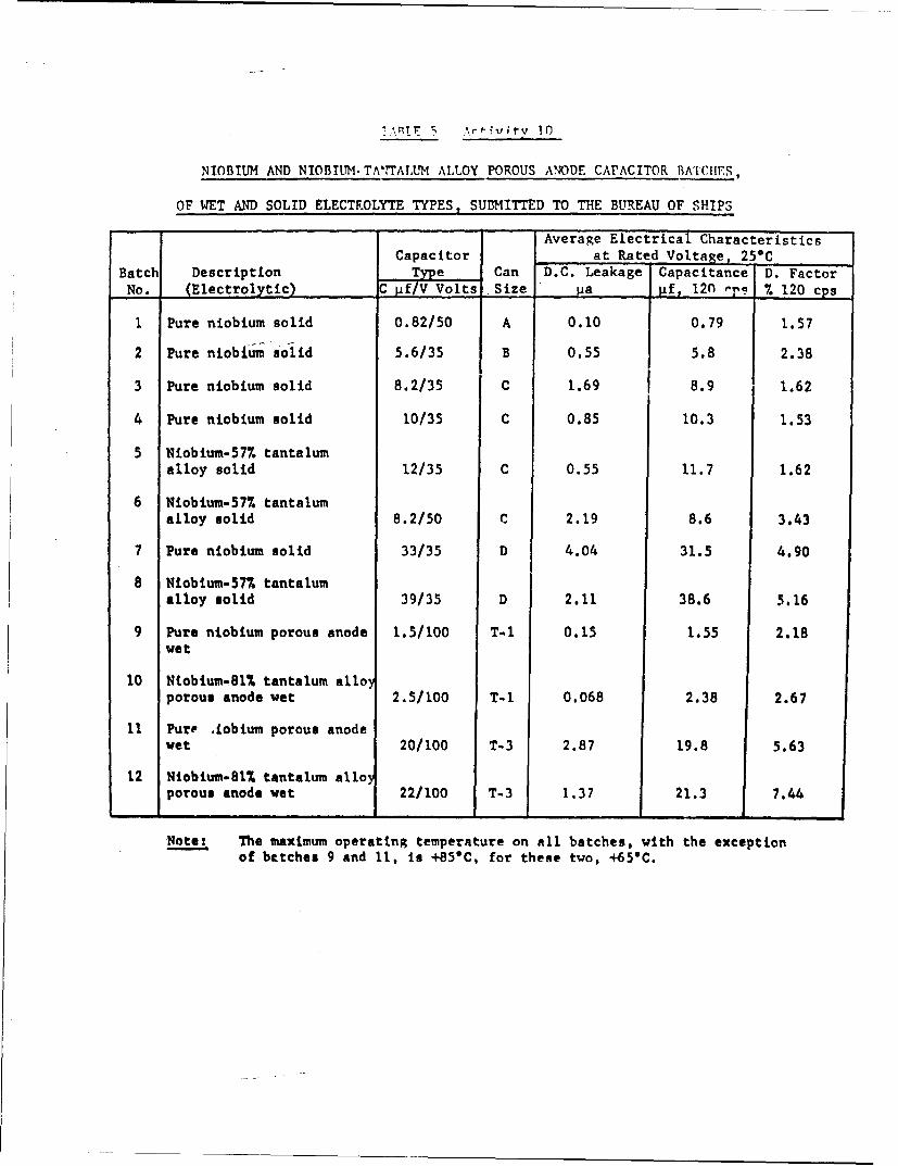
T•ATIr A v i vi-v 10
NIOBIUM AND NIOBIUM- TA'"TALUM ALLOY POROUS ANODE CAPACITOR BATCIHES,
OF WET AND SOLID ELECTROLYTE TYPES, SU•MTTTED TO THE BUREAU OF SHIPS
Average Electrical CharacteristicsCapacitor at Rated Voltage, 25*C
Batch Description Type Can D.C. Leakage Capacitance D. FactorNo. (Electrolytic) C Pf/V Volts Size pa pf, 12n rpi % 120 cps
1 Pure niobium solid 0.82/50 A 0.10 0.79 1.57
2 Pure niobium solid 5.6/35 B 0.55 5.8 2.38
3 Pure niobium solid 8.2/35 C 1.69 8.9 1.62
4 Pure niobium solid 10/35 C 0.85 10.3 1.53
5 Niobium-57% tantalumalloy solid 12/35 C 0.55 11.7 1.62
6 Niobium-57. tantalumalloy solid 8.2/50 C 2.19 8.6 3.43
7 Pure niobium solid 33/35 D 4.04 31.5 4.90
8 Niobium-57% tantalumalloy solid 39/35 D 2.11 38.6 5.16
9 Pure niobium porous anode 1.5/100 T-l 0.15 1.55 2.18wet
10 Niobium-Sl% tantalum alloyporous anode wet 2.5/100 T-1 0.068 2.38 2.67
II Pure Liobium porous anodewet 20/100 T-3 2.87 19.8 5.63
12 Niobium-81% tantalum alloporous anode wet 22/100 T-3 1.37 21.3 7.44
Notes The maximum operating temperature on all batches, with the exceptionof betches 9 and 11, is +85"C, for these two, +65"C.
00
I 0
I 0
03
o atz M:
"I / 0
I 00 0
i -1 0
0
flf0 80cU
_0
0-0
00 00 0 0 do 0ol 0
30NV.lO~VdVO NI 39NVHZO %

000
jLL..0
>ý- J 3z00w0
00 ~ 0
zZi?
u"-0' I ) N -
0 0
0
-r ixI
=)I I"-VD LND~

00
to
(n
w Ji LL
0
zo IL, • ==@00
> 00zo_._.
a• . to a. oo.< W U C--.
II-
0 0 0 0 p 0 0r
_ m
r -r[Z _
wm 8~~~~~a ,X J- T00 ''
3DNVZIt~dV' NI 3DNVH3 IN33W~d

0
00
03C
000
0 (A00
iz : 0w~~9 00m
U34~D~ Z5 C t
40 0 0 0
bi 0 0
00
a,

Distributinn Lint for Progress Report5;Generated Under ';Obsr-87478
No. Copies
Chief, Bureau of Ships 4Department of the NavyWashington 25, D. C.Attn: Code 681A2C (H. Nordenberg)
Chief, Bureau of Ships 3Department of the NavyWashington 25, D. C.
Attn: Code 335
DirectorNaval Research LaboratoryWashington 25, D. C.
Attn: Technical Library
CommanderNew York Naval ShipyardMaterial LaboratoryNaval BaseBrooklyn 1, New YorkAttn: Technical Library
Chief, Bureau of Naval WeaponsDepartment of the NavyWashington 25, D. C.Attn: Code RAAV4123
Commanding Officer and DirectorU. S. Navy Electronics LaboratorySan r ego 52, California
Attn: Mr. R. B. Jordan
DirectorU. S. Navy Underwater Sound LaboratoryNew London, Connecticut.Attn: Technical Library
DirectorNaval Ordnance LaboratoryCorona, California
Attn: Mr. Robert Conger
CommnnderNavy Ordnance LaboratorySilver Spring, MarylandAttn: Technical Library

No. Copier
Manager of EngineeringGeneral Electrical CompanyP. 0. Box.158..- -
Irmo, South CarolinaAttn: Mr. N. R. Clark
Office of Naval ResearchWashington 25, D. C.Attn: Code 421 (Dr. Sorrows)
DirectorNational Bureau of StandardsWashington 25, D. C.Attn: Mr. G. Shapiro
DirectorNational Bureau of StandardsBoulder LaboratoriesBoulder, ColoradoAttn: Technical Library
Commander 10Armed Services Technical Information AgencyArlington Hall StationArlington 12, Virginia
Advisory Group on Electron Devices 28th Floor346 BroadwayNew York 13, New York
Commanding GeneralU. S. Army Signal Research and Development LaboratoryFort Monmouth, New JerseyAtt.. SIGRA/SL-PEP (Mr. H. L. Stout)
Commanding GeneralU. S. Army Signal Supply Agency225 South 18th StreetPhiladelphia 3, Pennsylvania
CommanderAeronautical Systems DivisionWright-Patterson Air Force Base, Ohio
Attn: Mr. Carl K. Greene (WWRNEM-l)
CommanderRome Air Development Center, ESDGriffiss Air Force Base, New YorkAttn: RCSSP (Mr. P. Ciannico)

No. Copies
Inspector of Naval Material I
Department of the Navy1783 East lith StreetCleveland 14, Ohio.
Attn: Mr. R. Donnelly
Inspector of Naval MaterialDepartment of the Navy1783 East llth StreetCleveland 14, OhioAttn: Mr. J. Heinal