i-r e p o r t ~ a g ~ mentation ii'-n~~r~~o780 2 3 i n413
TRANSCRIPT

50272 -101
I-R_E_P_O_R_T_~_A_G_~_MENTATION II'-N~~R~~o780 341 ._ __ 1
2
._. ___ .__ _ 1
3
. pitrZ9J N413 4. Title and Subtitle 15. Report Date
Seismic Response Behavior of Buried Pipelines (Seismic Vulner- I June 1978 ability, Behavior and Design of Underground Piping Systems, ~.------------------Techni cal Report No. 5L_
..... - ---- --_ .. _. -------7. Author(s) B. Performing Organization Rep!. No.
I-:-'L...o...!.R,,-"---llMJWatn.Llg;H,,--,-,K'::'-Ll!Mawn~ClUh .... eI.LO ~g -----------. _______ . _____ 1---5----.--_____ -1 9. Performing Organization Name and Address 10. Project/Task/Work Unit No.
Rensselaer Polytechnic Institute Department of Ci vil Engineering Troy, New York 12181
12. Sponsoring Organization Name and Address
Applied Science and Research Applications (ASRA) National Science Foundation 1800 G street, N.W.
.-. _ ......... ------.---. 11. Con!ract(C) or Grant(G) No.
(e)
(G)
.. _ . __ . __ EN\j]_614.aa.4. ____ . __ .. _~ 13. Type of Report & Period Covered
Techni cal --
14.
Washington, DC 20550 I--....:.:..:::.=-:.:....:...:.:...t...=...::...:.:..~::...::...--=:..::..:..=.-=-__________ . __________________ .. __ ... ___ . __ .. ______ . ___ . __ ---/
IS. Supplementary Notes
1-------------· --_ .. - .. --. -- .. - ...... . _._.- ~.------·16. Abstract (Limit: 200 words)
Overall aims of this research are to develop a systematic way of assessing the adequacy and vulnerability of water/sewer distribution systems subjected to seismic loads and also to develop future design methodologies for water/sewer systems. This paper reports pipeline damages caused by earthquake excitations in the longitudinal direction of a pipeline have been observed to be a major mode of failure. A simplified quasistatic seismic deformation analysis neglecting the dYnamic terms for buried pipelines subjected to earthquake motions in the axial direction is proposed. The analysis involves the solution of a system of static equilibrium equations of a pipeline which con sists of rigid pipe-segments and flexible joint springs. Using this model, parametric studies involving soil-pipe interaction parameters, time delay of the traveling seismic waves, soil variations along the pipeline, end conditions, and variation of the seismic wave form are performed. Results obtained indicate that the delay time of seismic waves and the non-uniformity of soil resistance have much greater effects on the response behavior of buried pipelines than other parameters.
17. Document Analysis a. Descriptors
besi gn Earthquakes Earthquake resistant structures Dynamic structural analysis
b. Identifiers/Open·Ended Terms
Buried pipelines Earthquake engineering
c. COSATI Field/Group
lB. Availability Statement
NTIS.
(See ANSI-Z39.1B)
Water pipes Water supply Sewer pipes
Hazards Piping systems Subsurface structures
19. Security Class (This Report) 21. No. of Pages
/6 20. Security Class (This Page)
See Instructions on Reverse OPTIONAL FORM 272 (4-77) (Formerly NTlS-3S) Department of Commerce
\
\


Seismic Vulnerability, Behavior and Design
of Underground Piping Systems
Seismic Response Behavior of
* Buried Pipelines
by
Leon Ru-Liang Wang and
Kwong-Man Cheng
Sponsored by National Science Foundation
Research Applied to National Neeqs CRANN)
Grant No. ENV76-l4884
Technical Report (SVBDUPS Project) No. 5
June 1978
Department of Civil Engineering Rensselaer Polytechnic Institute
Troy, New York 12181
* To be presented at ASME Annual Winter Convention, San Francisco, CA, December 11-15, 1978.
1 i \ \


rii'1 ~ Department of Civil Engineering Telephone - (518) 270-6360
Rensselaer Polytechnic Institute Troy, New York 12181
No. 1
List of NSF SVBDUPS (Seismic, Vulnerability, Behavior
and Design of !iping ~stems) Project Technical Reports
Leon Ru-Liang Wang and Michael J. O'Rourke State of the Art of Buried Lifeline Earthquake Engineering Jan. 1977
. Also in ASCE Proceedings of Current State of Knowledge of Lifeline Earthquake Engineering Conference, Los Angeles, CA, Aug. 1977~ pp. 252-266
No. lA Leon Ru-Liang Wang and Michael J. O'Rourke An Overview of Buried Lifeline Earthquake Engineering Jan. 1978 Also to be published in ASCE Journal of Technical Councils
No. 2R Leon Ru-Liang Wang Vibration Frequencies of Buried Pipelines Jan. 1978 Also to be published in ASCE Journal of Technical Councils
No.3 Michael J. O'Rourke and Eric Solla Seismic Risk Analysis of· Latham Water District, Albany, New York June 1977
No. 4 Michael J. O'Rourke and Leon Ru-Liang Wang Earthquake Response of Buried Pipelines March 1978
No. 5
Also in Proceedings of ASCE Geotechnical Division SpeCialty Conference on Earthquake Engineering and Soil DynamiCS, Pasadena, CA, June 1978, pp. 720-731
Leon Ru-Liang Wang and Kwong-Man Cheng Seismic Response Behavior of Buried Pipelines June 1978 Also in preprints of ASME Winter Conference, San Francisco, CA., Dec. 1978·
\, \
1\1

ACKNOWLEDGEMENT
This is the fifth in a series of technical reports under the general title
of 'Seismic Vulnerability, Behavior and Design of Underground Piping Systems' .
(SVBDUPS). The research has been sponsored by the Earthquake Engineering Pro
gram of NSF-RANN under grant No. ENV76-l4884 in which Drs. S.C. Liu and William
Hakala are the Program Managers. Dr. Leon Ru-Liang Wang is the Principal Inves
tigator of this Project.· The overall aims of this research are to develop a
systematic way of assessing the adequacy and vulnerability of water/sewer dis
tribution systems subjected to seismic loads and to develop future design
methodologies.
The authors wish to express their appreciation for the inputs and discussions
from all members of the research team during the course of investigation.
Appreciation also goes to the Advisory Panel which consists of Mr. Holly <\,
Cornell, Board Chairman of CH2M Hill, Inc., Corvallis, Oregon; Mr. Warren T.
Lavery, Superintendent of Latham Water District, Latham, N.Y.; Dr. Richard Parmelee,
Professor of Civil Engineering, Northwestern University and Drs. Jose Roesset and
Robert Whitman, Professors of Civil Engineering, M.I.T. for their constructive
comments and suggestions.
The typing and proofreading of this report by Mrs. Jo Ann Grega is also
appreciated.
Please note that although the project is sponsored by the National Science
Foundation, any opinions, findings and conclusions or recommendations expressed
by this publication are those of the authors and do not necessarily reflect the
view of NSF.
iv

ABSTRACT
Pipeline damages caused by ear~hquake exci~ations in the longitudinal direction of a pipeline have been observed to be a major mode of failure. A simplified quasi-static seismic deformation analysis neglecting the dynamic ~erms for buried pipelines subjected to earthquake motions in the axial direction is proposed. The analysis involves the solution of a system of static equilibrium equa~ions of a pipeline which consists of rigid pipe-segments and flexible joint springs.
Using this model. parametric studies involving soil-pipe interaction parameters. time delay of the traveling seismic waves. soil variations along the pipeline. end conditions and variation of the seismic wave form are performed.
Results obtained indicate that the delay time of seismic waves and the non-uniformity of soil resistance have much greater effects on the response behavior of buried pipelines than other parameters.
NOMENCLATIJRE
i n t
Dt
Xi,xi,xi
xGi'xGi,xCi
f(t) .g(t) ,h(t)
A max
An index Nu=ber of pipe segment T:!:me Constant delay time of seismic wave be1:Veen 010 pipe segments' fn constant segment leng~h system used in ~he parametric study Distributed soil damping coefficient along fth pipe segment Total soil resistant force (spring + damping) on i th pipe segment Distributed soil spring constant (force/length) along i th pipe segment Acceleration. ~elocity. displacement of ith pipe segment Acceleration. velocitYehdisplacement of ground above i pipe segment Acceleration. velocity> displacement of ground at beginning of pipeline Acceleration, velocity, displacement of ground at end of pipeline' Seismic acceleration. velOCity, displacement time functions Maximum acceleration of a seismic record th Damping coefficient of i joint dashpot
1
Co
C n
Fi
ICi
KO
K n
Li Mj; Ui
V max
Vs1
'Ii
(1i
6:\;
liT!
Yo
Yn
{~} . {~}, {~}
{~},. {~}
Cd] Ik) [Cl [C t ]
[IC) [IC']
[M]
INTRODUCTION
Pipeline beginning restraint damping coefficient Pipeline end restraint damping • coefficient Total restrained force (spring + dashpot) of i th joint ith joint spring constant Pipeline beginning restraint spring constant Pipeline end restraint spring constant th ' Length of i pipe segment Mass of i th pipe segment
th Exutlsi011/eollt:r:Aeti-on of i joint spring '!;3xi= veloc:l.ty of a seismic record Seismic wave propagation velocity within i th pipe segment Relative displacement between ith pipe segment and the ground displacement above Normalized ±th joint spring constant ICi/kiLi Normalized soil restraint constant along i th pipe segment ki/kl Delay time of seismic wave from beginning of pipeline to ith pipe segment Normalized pipeline beginning restraint spring constant KO/klLl Normalized pipeline end restraint spring constant Kn/kuLn Pipe segment acceleration, vel~ city. displacement vectors Ground velocity, displacement vectol."S Damping matrix of soil Stiffness matrix of soil Damping matr:bt Qf joine dashpots Equivalent damping matr1.x of pipeline beginning and end dashpoes Stiffness matTtx of joint s~rings Equivalent stiffness matrix of pipeline beginning and end re5traints Mass matrix of pipe segments
Earthquake damage has become an increasing threat to human life in recent years due to its frequent

occurrence. The design of structures against earthquake has long been a practice in areas where earthquakes often occur. However, much effort in the past has been concentrated on the above-ground structures, such as buildings, towers and bridges. As to underground structures, which are just as vulnerable in the event of earthquakes, very little discussion in the literature has been found until recently.
Past observations of actual earthquake damage to underground pipeline systems show a variety of failure modes (longitudinal, shear and bending). In particular, most literature surveys on pipeline failure due to earthquakes indicated joints being pulled out and crushed are the most common modes of failure (5,6,7, 20,21). The response behavior of buried pipelines during seismic shaking has been found to be predominant in the axial direction of the pipeline (8,10,11, 14,16,18). From these observations it is logical to believe that the failure mode or response behavior of buried pipeline due to longitudinal earthquake motion is, if not the most important, certainly one of the most important characteristics deserving close attention and thorough investigation.
State of the art papers (9,20,21) on buried lifeline earthquake engineering have been published recently. Analytically, the response behavior of underground piping systems has been studied by the investigators at Weidlinger Associates.(4) and at Rensselaer Polytechnic Institute (15). To aid the design of buried pipelines, both the static displacement approach (13,17) and the dynamic interference response spectra approach (12) have been proposed.
The purpose of this paper is to stud~r the response behavior of long buried pipelir.es d.,,'; '~o
seismic excitations in the direction of the pipeline axis by a simplified quasi-static analysis model.
Note that since the dynamic effects 00 the response behavior of buried pipelines have been found to be negligible (8,10,14,18), the inertia and damping cerms in the dynamic equations of motion can be dropped. Thus, the equilibrium equation is essentially a static one. Since the input ground motion is a function of time, the response will also be a function of time. Therefore; the analysis is called a quasistatic analysis.
GENERAL DESCRIPTION AND ASSUMPTIONS
The buried piping system described in this paper is a long pipeline (typical of water/sewer transmission lines) buried underground. The pipeline is made up of pre-fabricated pipe segments. These pipe segments are connected at joints, which are sealed by a rubber gasket or caulked by cement/lead. Figure 1 shows a buried piping system sch~tically.
»;;70;;;;/1;;; ;;;777/77177771; III 7
Fig. 1 Schematic of A Ruried Pipeline
The earthquake damping forces to buried pipelines include seismic shaking/vibrations, fault displacements, tectonic uplifts/subsidences, landslides, soil liquefaction, etc. The modes of failure of pipelines due to tectonic uplifts/subsidences, landslides or soil liquefaction are catastropic and will not be considered. This paper limits discussions·
2
to the response behavior of buried pipelines due to -seismic shaking/vibrations.
Due to the motion of the ground relative to the pipe segment during earthquakes, resistance between the pipe and the surrounding soil develops. The soil resistance to the pipe motion is assumed to be uniformly distributed and linearly proportional to the relative displacement between the pipe and the ground (Fig. 4). To model such soil reSistance, a uniformly distributed soil spring, k, is proposed.
The jOint resistance between two pipe segments is modeled by a joint spring, K, and a dashpot, C, as shown in Fig. 2. Note that the joint spring constant from a rubber-gasket, cement-caulked or lead-caulked Joint is in general very small as compared to the stiffness of pipe itself or the resultant soil spring constant along a pipe segment.
))/);;777);;;))))71))7;;)7717))
Fig. 2 A Buried Long Pipeline Model
Under seismic excitation, both pipe segments and joint springs are all subjected to the imposed ground displacements/strains. However, it is anticipated that most of the ground displacements/strains will be absorbed by the movements of jo~t springs and very little by straining of the pipes. For simplicity and conservatism (in estimating joint extension/contraction) purposes, all pipe segments will be assumed to be infinitely rigid.
An earthquake motion traveling along a pipeline resembles the problem of wave propagation in an elastic media. An incident earthquake at one end of a pipe segment will not sfmultaneously reach the other end some d±stance away. Thus, for wave propagation problems, a time lag is generally associated with the wave in the direction· of propagation. Since the dissipation of seismic wave energy is negligible along a pipeline duriug the period of investigation, we assume that the wave form remains constant in the course of propagation.
Further assumptions or limitations for the simplified model wi~l be made in later sections.
FORMULATION OF THE PROBLEM
A long buried piping model consisting of n-segments is shown in Fig. 2 where Ml, M2, ••• Mi , .. Mn are equivalent masses of each segment of underground pipes which should include the mass of the pipe and the soil that moves with the pipe; Kl, K2, ••• Ki , •• Ku-l and Cl , C2, ••• Ci , •• Cn- l are spring constants and damping coefficients at joints between pipes; Ka, Kn and CO, Co are spring and damping constants at the end supports.
The coordinates that define the motion of the ground and the pipe during an earthquake are shown in ·Fig. 3 in which Xl' x2' •• Xi' •• ~ are longitudinal displacements of mid-sections of pipe segments; XCI' XC2' •• Xen are the corresponding ground displacements in the direction of the pipeline axis; xeo and XGn+l are the ground movements at the ends; Ll ,L2 , •• L
i, •• Ln are pipe lengths.

MJ::~~. x X +1
~~ LI . Ln
Fig. 3 Coordinates of Buried Pipeline Model
/
XGi
.
/SOil Deformation
Fig. 4 Dynamic Equilibrium of A Pipe Segment
Referring to Fig. 4, the dynamic equilibrium equation (2) for pipe segment i is:
(1)
in which Mi X. is the inertia force; F1_ ' Fi are joint resistafit forces at both ends of t5e p~pe and fi is the resistance from soil surrounding the pipe.
Using the coordinates, xi > Xci' xi > xi_I' xi+l > xi' the above resistant forces can be expressed as:
Fi z Ci(xi+l-xi ) + Ki(xi+l-xi )
Fi _1 2 Ci_l(xi-Xi_l) + Ki_l(xi-xi_l)
fi diLi(xi-xGi) + kiLi(xi-xGi) } (2)
where di and ki are damping and spring constants per unit length of surrounding soil.
Substituting Eqn. (2) into Eqn. (1), the equation ~f motion is obtained:
Mi~i+Cl_l(ii-ii_l) + Ki_l(xi-xi_l)
- Ci(Xi+l-Xi ) - Ki(xi+l-xi )
+ diLi(Xi-XGi) + kiLi(xi-xGi}
- 0
After rearranging, Eqn. (3) becomes
Mi;i-Ci_lXi_l + (Ci_l+Ci+diLi)xi
-Cixi+l-Ki_lxi_l + (Ki_l+Ki+kiLi)xi-Kixi+l
- diLiXGi + ki Li%Gi
Let us define
(3)
(4)
3
Ci - Ci _ l + Ci + diLi
Ki - Ki _1 +,Ki + ~iLi
Eqn. (4) is simplified to:
Mixi - Ci_lXi _l + ciii - CiXi+l
- Ki_lXi _l + KiXi - Kixi +l
- diLixGi + kiLiXGi
(5)
(6)
Note that Eqn. (6) is valid for any i-values except i-I and i - n in which case the end-restraint springs are involved.
When i-I, xO and xo' which do not exist, are replaced by *co and xGO to obtain the equation of motion for the beginning pipe segment as:
~1+{CO+Cl+dlLl}Xl-ClX2+(KO+~+klLl}Xl-KlX2
2 COiGO+dlLl~Gl+KOxGO+klLlXGl (7)
Similarly, when i - n, Xn+l and Xn+l' which are not defined, will be replaced by Xcn+l and xGn+l' and ·the equation of motion for the end pipe segment becomes:
.. Mnxn - Cn_1xn_1 + (Cn_l + Cn + dnLn)xn
- Kn_1xn_l + (Kn_1 + Kn + knLn}xn
a CnXGn+l + dnLnXGn + KnXGn+l + knLnxGn (8)
Combining Eqns. (6) to (8), the system of equations of motion for a pipeline of n-segments in matrix form will become:
where
{.!.} ..
.. [M] {.!.} + [cl {.!} + [K] {.!.}
.. [d] {~}+{k]{.!c}+{C']{~·}+{K·]{.!c'} (9)
~l x2
Xi {~}-
x n
n x 1
Xl x2
Xi
X n
nx 1
x n
n x 1
(10)
are the acceleration, velocity and displacement vectors of the pipeline system respectively. The system masS matrix Is:
[Mj- (ll)
n x n
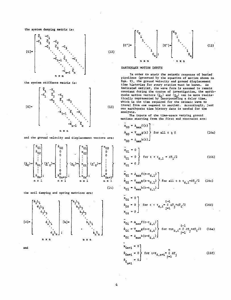
the system damping matrix is:
Cl -Cl -C
l C
2 -C2
-C2 <=3 -C3 [C]- (12)
the system stiffness matrix is:
[Kl" (l3)
K K - n-l- n
n x n
and the ground velocity and displacement vectors are:
XCI XCO xGl xGO XG2 a XG2 a
a a
{~}2 xCi {x' } .. -G {~}- xCi {x' }'" -G
a a xGn
.0 0 XGn+1 xGn xGn+l:
n x 1 n x 1 n x 1 n x 1
(14)
the soil damping and spring matrices are:
dlLl kILl
d2L2 k2L2
d3L3 ~L3
[d]" diLi [k]- kiLi
d L kL n n n n
nxn n x n
and
4
Co KO
1 1 1 1
[C'l- (K'l- (15)
1 1 Cn K n
nxn nxn
EARTHQUAKE MOTION INPUTS
In order to study the seismic response of buried pipelines (goveTned by the equation of motion shown in Eqn. 9), the ground velocity and ground displacement time histories for every station must be known. As indicated earlier, the wave form is assumed to remain constant during the course of investigation, "the earthquake motion vectors {~} and {~} can be mOTe realistically represented by ~corporafing a delay time, which is the time required for the seismic wave to travel from one segment to another. Accordingly, just one earthquake time history data is needed for the analysis.
The inputs of the time-space varying ground motions starting from the first end restraint are:
~GO ,. Amaxf (t)} " xco - Vmaxg(t) for all t ~ 0
xCO .. Amaxh(t)
xGi
-OJ i-I XCi ,. 0 for t < td i a E AT j +AT
i /2 , j-l
XCi a· 0
XCn+l - O} n
*Gn+l .. a for t<td +1" 1: ATj ,n j-1 x .. 0
Gn+1
(16a)
(16b)
(16c)
(16d)
(16e)
(l6f)

.. xCn+1 • Amaxf(t-td,n+l)}
xGn+l • Vmaxg(t-td,n+l) for
xGn+l - A~h(t-td,n+l)
n t;!td +1- 1: ATj ,n jotl
U6g)
where Amax, Vmax' 6max are expected maximum values of acceleration, velocity and displacement of seismic data. ATi • L1/VSi is the delay time for a seismic wave traveling Li-distance of pipe, VSi • wave velocity of soil surrounding ith segment of the pipeline.
SIMPLIFIED QUASI-SIATIC ANALYSIS MODEL
The system of dynamic equations developed in the previous sections involved inertia and damping effects, which, together with the time delay effect in ground excitations, become an extremely tedious problem to solve. In terms of computing time, it is a very expensive task. Furthermore, it is very difficult, if not impossible, at this time to obtain reasonably accurate values for the equivalent mass and damping coefficients for the system.
For general design purposes, it is desirable that the deSign procedure be simple and the analysis be economically feaSible, yet reasonably correct. For this reason, we need a simple model which will provide results similar to the exact model for the same problem.
In recent years, several investigations (8,10, 11, 16) done in Japan, indicated that dynamic effects are not significant in the behavior of underground piping systems. In view of this information, we will convert the dynamic model i~to a simple guasi-static problem by neglecting the {~}, {~.l and {~} terms. For simplicity, we assume equal pipe segment length in the analysis model. The system of equations becomes:
(17)
in which [K) is a tridiagonal-symmetrical matrix, [k] and [K'1 are diagonal matrices. Or in extended form, the governing equations of equilibrium are as follows:
~ -~ Xl klL XCI
-IS. K2 -~ x2 ~L xC2 .
-Ki_
l Ki -K i Xi kiL XCi .
-K it x k L Gn n-l n n n
nXll nx 1 n x n nx 1
ICO
xGO 1 0
.+ 1 0 (18)
I 0 1 0 K xGn+l n
nxn nxl
Note that the ground displacement vectors, {xC} and {x'C} are constantly changing from one instant to another due to the delay time effect although the wave form remains unchanged.
For simplicity, we further assume a constant delay time, DT for the seismic wave traveling from one segment to another in a given system. Using the first
5
pipe segment a~ the tfme reference, the tDput ground displacement vectors can be defined as follows:
{X' }. -G
h(t)
h(t-DX)
h (t-[ t-lJDT)
h(t-[n-l]DT)
h(t + 1- DT}
o o
o o 1
h(t-fn - I]DT
(l9a)
(19b)
Now, let us define the follOWing parametric constants for the quasi-static analysis:
1) Normalized Joint Spring Parameters
aizKi/kiL i .. 1 to n-l (20)
2) Normalized End Restraint Spring Parameters
Yo .. KO/k1L (21a)
Y .. K Ik L n n n (21b)
3) Soil Resistant Spring Ratios
Si .. k/kl ; i ,. 1 to n (22)
Substituting these parameters [Eqns. (20) to (22)} into Eqn. (l8) , the system of the governing equation becomes:
(YO-T-<ll+l) -«1
-(11 (al+a2S2+S2) -<12S2
1 xGl 62 xG2
St xGi
. ) (0 III 1+Y S +6 n- n- n n n
YO 1
.xGO 0
+ 1 0
1 0
x n
(23)
6n xGn Yn6n xGn+l
in which all elements in the matrices are dimensionless quantities. It is interesting to note that this governing equation for the analysis of buried pipelines does not involve pipe segment length variable, L, since its effect has been built into the relative values of a, a, and y. Furthermore, the effects of pipeline length can be studied by varying the number of segments and the magnitude of DT used in the analysis.
For the analysis, the following special cases of a, Band yare studied:
1) Pipeline buried in uniform soil environment,
(24)

2' Pipeline without end-restraints
and i'n - a (25)
3) Pipeline with uniform joint construction
(II .. (12 .. • • Cli .... • (In_l .. (1 (26)
which is assumed to be the case in this paper. As indicated earlier, the joint resistance is MUch smaller than the soil resistance along a pipe segment, thus a in general will be a small quantity even though the effects of (l are studied ~arametrically.
METHOD OF SOLUTION
Since the system of governing equations shown in Eqn. (23) for the quasi-static analysis model involves only symmetrically tridiagonal and diagonal matrices, it is more efficient and advantageous to convert [X} into an upper triangular matrix by eliminating the subdiagonal elements. The system can then be solved directly by backvard substitution (3). This scheme, which eliminates matrix inversion, reduces computer_storage, and has less truncation error.
The response of the pipe-segment Xi's were computed at each time step for the whole time-history of the input earthquake record._ These responses were then used tD determine the following two parameters:
Yi - xt-XGi - Xi (t}-xG(t-[i-l]PT); i-I to n
Ui - xt-xi +l (271
is the relative dis~laeement between the ground and the pipe-segment t._ is the extension/contraction of ~th joint spring between two adjacent pipe-segments._
These two parameters enable us to deduce the general response behavior of the pipeline under a certain earthquake record and other prescribed conditions.
Note that a computer program for the simplrfted quasi-static analysis of buried pipelines has been vritten and reported by Cheng (1). this paper only presents the important results/conclusrons without details. Since the seismic failure criteria of buried pipelines will be reported later (19) this paper discusses only the elastic response behavior.
Computations were made for various conditions by varying the value of different parameters, such as ' the time delay, the number of pi~e-segments used, the soil/joi~t spring stiffness parameters, the end restrai~t coefficients, and the relative soil resistant ratios, etc. The computer program finds the maximum values of Y and U for each condition and subsequently outputs Ymax and Dmax and the time and
_ location when the maximum Y and U occur.
RESULTS/DISCUSSION
TTJo sets of real earthquake records, xG(t) were used. They are the El Centro ~~y 18, 1940 S90W component and SOOE component, whose displacement time history records are shown in Figs. 5 and 6 respectively.
6
.. ZQ
'-4_
2.
tL UIITJItC) .... v ... ~ 'lOW ~O"~"T ~ ~ __ ..... 7.7 ...... ',."'.
0. 10 ". ~o H. .30 34
Tu., ,,. UCOtfDS
Fig. 5 Referenced Ground Displacement Input
1M QI tf.. Ct.fI(fltQ ..... .,. '8,1940 500£ COMPOICIff ...... iIoIac ....... .,. 4~lI.ncf1 .. (10." tMI
lO- ~Q 2. sa TM£ 'If SUCHOS
Fig. 6 - Typical Ground Displacement Input
To establish a basis for comparison of the seismic response behavior of buried pipelines for various parameters, the fol10~ng conditions are arbitarily set as the 'reference conditions':
Number of ~sses M" 6-End restraint conditions None, Le. YO·O and
- yn-O Soil conditions
Delay time Seismic input
Uniform, Le. 13 .. 1,1,1,1,1,1 PT .. 0.1 Second El Centro May 18, 1940 S90W Component
Note that the seismic response behavior of buried pipelines presented in this paper are limited to the maximum rela.tive d-isplacements betTol'een the pipe segment-and the ground, ~, and oetTol'een pipe segments themselves, Umax (for the rigid pipe segment assumption, Umax represents tne joi~t spring elongation! shortening conservatively) for various joint spring constants.
For the evaluation of the effects of a particular: parameter to the response behavror,Ymax and umax, -only that parameter wi2l be varied from the above mentioned referenced conditions.
Effect of Joint Stiffness The results of the relati~e displacements between
pipes, Umax and the relatiYe displacements between pipes and their surrounding 5011. Ymax against normalized joi~t spri~g stiffness, a are shown in Fig. 7 and Fig. 8 respectively.
One can see from Fig. 7 that the relative displacement between pipe segments, Umax, (J.e. the indication of joint extension or contl"action) 1s about 1.4 inches 0.56 em) for small joint stiffness (low <:1
value) and decr~ase asymptotically approachi~g zero as a increases toward inf1~ity. On tbe other hand, Fig. S shows that the relative displacement between the pi-pe segment and ground, Ymax is very small when a is

small and increases tremendously as a increases beyond 0.1. ·The low Ymax quantity for small a values agrees veIl with the observations by the investigations (8, 10,11,14,16) in Japan. Thus, for further discussions, the joint stiffness parameter has been limited to less than 0.1.
IN CM
4. 10.0
2. ~
Fig. 7
IN CM
7.
6. e.
5.
Ymo•
4'1 10•
1
+ l
0.0 0.001
REFERENCED CONDITIONS: E.cit"Uon - EI Cont", May 18,1940 S 90tV Comp. aetG_ 1,1,1,1, I, I Gan.mo_ 0,0 104- 6 DT - O.l •• e.
ALPHA- Stiffness of en, Stlffne •• of .oil
U vs a Under Referenced Conditions max
0.01
REFERENCEO COHDITIOHS: Excitation_ EI Contra May 18.1940 S90W Comp. BetQ - 1,,1,1,1 .. 1.1 Gammo. 0,0 101_ S DT- OJ •• e.
Ql
ALPHA
Fig. 8 Ymax
vs a Under Referenced Condi'tions
Effect of Non-uniformity of' Surrounding . Soils The objective of this study i'5 to verify the
statement that the earthquake damage of buried pi~elines was higher in regions of transrtton iraQ one soil type to another as reported' by 'Kubo et al (91.
The effects of varration of the soH condi1:i~s· for a pipeline on Umax and Y
max are sho~ in Ftgs, 9
and 10.
7
IN eM 4.0
10.0
~5 9.0
8.0 3.0
7.0 Umo•
2.5
5.0
2.0 5.0
l!I 4.0
3-0
1.0
2.0
0.5 1.0
0.0 0.001
e.to. 1,1,1,9,9,9
E,citatlan. EI Contra Moy Ie. 1940 S90W Com ... G-mo·O.O.OO M. 5 CT. 0.1 He.
e.'a. I I 1,4,4,4
eota. 1,1,1,1,1,1
0.01
ALPliA • 511', .... of ,oint ~hffi1111 Of ,oil
-
1 OJ
Fig. 9 Effect of Non-Uniformity of Soil on Umax
IN
2!1
2.0
Y nMll
l5
La
0.5
0·0
eM
s.o
'-0
4.0
3.0
2.0
1.0
0.001
E,eilolion. EI Centro Moy 18, 1940 SSOW Comp. Gatnmo· M. OJ) ,... 6 CT- OJ •• e.
S.ta- 1,1",9,9,9 B.t~ - 1,1,1,4,4,4
a.to .. 1 •• ,J,I,I.!
0.01 ALPHA
Fig. 10 Effect of Non-Uniformity of Soil on Ymax
In these tvo figures, the bottom curve, denoted by BETA· 1,1,1,1,1,1, represents the case of uniform soil condition. The middle curve denoted by BETA s 1,1,1,4,4,4 represents the effect of soil stiffness surrounding the last three pipe segments which is 4 times greater than those surrounding the first three pipe segments. The top most curve, denoted by BETA s 1,1,l,9,9,9, represents the effect for even higher' relative difference in soil strffness in tvo regions. These curves indicate a considerable increase in Umax values as the soil is changed from a uniform condition to a non-uniform condition. Thus, Kubo's observation is verified.
Effect of Delay Time The delay time of seisurl;c waves traveling fraQ
one pipe segment to another is,determtned by two

variables. One is the length of the pipe segment and the other is the seismic propagation velocity which is related to the soil stiffness. Thus, one can interpret the increase of delay time as an increase in pipe segment length or by a decrease in soil stiffness.
By changing the delay time, DT, from the 'reference conditions', the effects of DT on Umax and Ymax are shown in Figs. 11 and 12. Apparently, the role of DT is to cause a magnification in both Umax and Ymax ' This result is quite consistent with the observations by Kachadoorian (5) who reported that pipelines in soft soil (longer delay time) experienced more damage during an earthquake than pipelines ~ firm soil.
Umaa
Vmaa
IN Clol
'l 3.5 9.0
8.0
3.0.
~ 7.0
2.5 i 6.0
2.oJ 5.0
l!! 4.0
3.0
LO
2..0
0.51 rO
0.0 0.001
OT·03 .... ----Excitation • EI Cenlro MOl 18,1940 S90W Camp. eeta. 1.1,1 ... 1.1.1 Gamma· 0.0,0.0 101- 6
CT·02see.
CT·O.ls ••.
•• 1 0.01
ALPHA .. Sliftness of jOi~1 Stiffness of 101i
••• I OJ
Fig. 11 Effect of Delay Time on Umax
IN CM
23
6.0
2..0 5.0
I.!! 4.0
1.0 3.0
2.0
0.5
1.0
0.0 0.001
Excilolion - EI CenlTo MOl 18, 1940 S90W Compo Ilelo- ~I.I,I,I,I GommG_ 0.0,0.0 101_ 6
0.01 ALPHA
DT - 0.3 lee. DT - O.2.oc. OT -0.1 •• ",
Fig. 12 Effect of Delay Time on Ymax
OJ
8
Etfect·of·End·Rescpatnt$ The effect of end restraints of a pi~eltne repre
sents the effect of an intersection/junction of a pipeline with a building, a pumping station or another pipeline. They are defined by a y quantity at ends (i.e., YO - Ko/klL and Yn • Kn/kuL). The effects of end restraints with y-va1ue ranging from zero (free end) to unity (equivalent to the same soil resistance along a pipe segment) on U
max and Ymax are shown in
Figs. 13 and 14.
IN CM
3.0
7.0
2.:1 6.0
Umaa %.0 :5.0
1.5 4.0
3.0
1.0
2.0
0.:1 1.0
0.0 0.001
Fig. 13
IN CM
2.:1
6.0
2.0 5.0
v".,a 1..5 4.0
1.0 3.0
2.0
0.5
0.0 0.001
Fig. 14
;:1~:Gtlonl:I,~:I,7,~ntro May 18,1940 S90W Camp.
Iot_ 6 DT- 0.1 ....
Gomma_ 1.0,1.0 Gamma - 0~,0.5
Gamma - 0.0.0.0
0.01
ALPHA. SlIffn ... II Joint Shffnesa of IQI'
0.1
Effect of End Restraints on U max
Eacilation - EI Centro May 18, 1940 S90W C<>mP-. eelO- 1,1,1,1,1,1 lot - 6 DT- 0.1 ••••
Gamma_ 1.0.1.0 Gamm ... 0.5,0.5 Gammo -0.0,0.0
0.01
ALPHA
OJ
Effect of End Restraints on Y max
One can see from these figures that the higher the end restraints are, the larger the relative displacements, Umax and Ymax, will be. Ho~ever, one can easily observe that such increases of Umax are not as high as those influenced by the changtng of soil uniformity or delay time. On the other hand, the increase of Ymax is much higher than those influenced bye and DT values.
Effect of Pineline Length Although the effect of pipeline length may be

studied by the effect of delay time described earlier, however, for a common delay time berween segments, the study of the effect of pipeline length would be more representative by varying the number of segments in the analysis model.
By varying M from 4 to 12. the results of U= and Ymax are given in Figs. 15 and 16. From these two figures, one finds that there are almost no changes of Umax and Ymax values for a < 0.1.
IN CM
~.O
4~ 12.0
11.0 4.0
10.0 3~
9.0
3.0 8.0 UmGll
2.5 7.0
6.0 2.0 5.0
EJdtallon- EI C..,',a May IB, 1940 sgow Compo Bela- I, "._ .' G""""Q- 0.0.0.0 OT. 0.1 .....
111·4
Sllffnes" 01 joint ALPHA • Stiff"." of .011
Fig. 15 Effect of Pipeline Length on Umax
IN CII
B.O
7.5 19.0
IB.O 7.0
17.0 6.l5
16.0 6.0 15.0
5.5 14.0 Y""",
13.0 5.0 12.0
4.15 11.0
4.0 10.0
3.S 9.0
3.0 B-O
7.0 2.5
6.0 2.0
~o
1.5 4.0
1.0 3.0
0.l5 2.0
lO 0.0
0.001
E.cllation. EI Centra May 18, 1940 S90W Com~ Beta - I. Gomma- 0.0,0.0 QT· 0.1 .....
0.01 0.1
ALPHA
/
/ I
I " " -' I /' . /
1/ . I
10.
'Fig •. 16 Effect of Pi-peline Lengtlt on Y II!3,X
From these observations, one ma~ conclude that the seismic response behavio~ of'a long buried pi7eline may be studied by a quasi .... stati'!: model cons·is·ting of 4 segments· or more. .
Effect of Seismic Wave Forms In this case, rwo El Centro Hay 18, 1940 records,
the S90W c01llponent <I,IId SOOE component were. used Yi'th
9
the maximum displacement for each case normalized to unity as shown in Fig. 17. Obviously. the response of a buried pipeline is dependent on the magnitude of the ground excitation. The purpose of the normalization of ground waves is to eliminate the absolute value comparisons. Thus, the effect of waveforms can be evaluated.
~ ~ & b ~ ~ ~ ~ ~ - ~. T1M£ De ~CONa
Fig. 17 Normalized Ground Displacement Input
The results of U and Y of a common subjected to two in Fig. 18 and
'reference' buried pi~ine mo~~ normalized ground waves are given Fig. 19.
III CM Gamma. 0.0,0.0 8ettl- ','.I,J,I,1 y. 6 QT- 0.1 ....
0.4 1.0
U 0..3 mcnt ~01'",al!:ed S 00 E COIT'lPOnent
0. 0.5 Normalized S90W Component
:j~~!!!I~'~ 0.00.1 0..01 0.1
Fig. 18
IPI CM
0.2 0.5
0.1
Sllfl.,.ss .f I"" ALPHA" Shtfnes. 01 soil
Effect of Wave Form on U max
Gomma - 0..0,0.0. Seta.. 1,1,1,1,1,1 ... 6 QT· 0.1 OK.
Itonnoli •• d SCC£ ComllNoo-_ized SgoW Cemp.
C.cl-_.-__ ...... _ ........... ==;;;;E===~ii:J:.-0.001 0..0.1 0.1
Fig. 19
ALPHA
Effects of ~ave Form on Y max
From these two figures, the response of Umax and Ymax seem to be a little higher under the SOOE C~ ponent tnan those under the S90W component. One

possible explanation is that the S~OE component exhibits several cycles of peaks at - 1 values while the S90W component experienced only one peak at the earlier stage. One may conclude that for the same maximum ground displacement, the seismic wave form with more cycles of the same peak will have higher effects on the response behavior. However, more research is required to study the true effect of wave forms.
SUMMARY AND CONCLUSIONS
The proposed simplified quasi-static analysis model seems capable of evaluating the general longitudinal response behavior of buried pipelines subjected to seismic shakings/vibrations. Parametric studies involving such important parameters as joint stiffness, uniformity of soil condition, delay time, end constraints, pipeline length and wave forms have been performed. The following gener'al concluding remarks can be made:
1. Higher joint stiffness will produce larger relative displacements becween pipe segments and becween pipe segments and the ground. For low joint stiffness, the relative displacement between pipe segments and the ground is very small, which agrees with the general field observations.
2. The effects of non-uniformity of soil environments and the delay time are the CWo most important influential parameters on the response behavior of buried pipelines. For uniform soil, the longer the delay time or the softer the soil stiffness, the larger the differences the transition of one type of soil to another, the higher the response will be.
3. The effect of end restraints is also observed, but such an effect is not as large as those caused by non-uniformity of soil and the variation of delay time.
4. For a pipeline consisting of pre-fabricated, segments, a model involving 4 or more segments will be accurate enough to determine its response behavior.
5. As to the effect of the seismic wave form, it is found that a wave form which has more cycles of maximum peaks seems to yield large response values. More research in this area is recommended.
ACKNOWLEDGEMENT
The paper is derived from the research project titled 'Seismic Vulnerability, Behavior and Design of Underground Pi-ping Systems (SVBDUPS1' sponsored by ASRA Branch (formerly RANN} of National Science Foundation under the grant No. ENV76-14884 in which Drs. S.C. Liu and William Hakala are the Program Managers. Their financial support and continuing encouragement about the research are appreciated.
Appreciation also goes to the Advisory Panel which consists of Mr. Holly A. Cornell, Board Chairman of CH4~ Hill, Inc., CorvalliS, Oregon; Mr. Warren T. Lavery, Superintendent of Latham Water District, Latham, N.Y.; Dr. Richard Parmelee, Professor of Civil Engineering, Northwestern University and Drs. Jose Roesset and Robert Whitman, Professors of Civil Engineering. M.I.T., for their constructive comments and suggestions.
The typing and proofreading of this report by Hrs. Jo Ann Grega is also appreciated.
Please note ,that although the project ts
10
sponsored by the National Sci~nce 1oundati~n, any opinions. findinglt and conclus'i'Otls' OT 't'ecolQlllendations expressed by this publ±cati~n are those of the authors and do not necessarrly reflect the view of NSF.
REFERENCES,
1 Cheng. K.M •• ~esponse Analysis of Bu:r:ied Pipelines". Master of Engineering Project Report, Civil Engineering Dept., Rensselaer Polytechnic Institute, Troy, N.Y., Hay 1978.
2 Clough. R.W. and Penzien, J., DynamiCS of Structures, McGraw-Hill. Inc., 1975.
3 Conte, S.D. and de Boor, C., Elementary Numerical Analysis, McGraw-Hill, Inc., 1972.
4 Isenberg, J., Weidlinger, P., Wright, J.P. and Baron, H.L., '~nderground Pipelines in A Seismic Environment", 'Proceedings of Specialty Conference on the Current State of Knowledge of Lifeline Earthquake Engineering, American Society of Civil Engineers, August 30-31,1977, pp. 267-281.
5, KachadooJri-au, R." '''Earthquake; CQ)?J:'e1<l,tj,Qn, Bet'Ween 1'i-peline Damage and Geologic Env:ixoTlll!ent", Journal of American Water WOlrks Association, VQl.. 68, No.3, March 1976, pp. 165 .. 167.
6 Katayama, T., Kubo, K. and Sato, N., "Earthquake Damage to Water and Gas Distribution Systems", Proceedings of U.S. National Conference on Earthquake Engineering, Earthquake Engineering Research Institute, 1975, pp. 396-405.
7 King, P. V. and Betz, J .H., "Earthquake Damage to a Sewer System", Journal of Water Pollution Control Federation, Vol. 44, No.5, Hay 1972, pp. 859-867.
8 Kubo, K., "Behavior of Underground Waterpipes During An Earthquake", Proceedings of 5th World Conference on Earthquake Engineering, International Association of Earthquake Engineering, Rome, 1974, pp. 569-578.
9 Kubo, K., Katayama, T. and Ohashi, A., "Present State of Lifeline Earthquake Engineering in Japan", Proceedings of Specialty Conference on the Current State of Knowledge of Lifeline Earthquake
'Engineering, American Society of Civil Engineers, August 30-31, 1977, pp. 118-133.
10 Kuribayashi, E., Iwasaki, T. and Kawashima, K., ''Dynamic Behavior of A Subsurface Tubular Structure", Bulletin of the New Zealand National Soci\jt7 for Earthquake Engineering, Vol. 7, No.4, Dec. 1974, pp. 200-209.
11 Nakayama, S., Kiyomiya, O. and Tsuchida, H., "Observation of Dynamic Behavior of Kinuura Submerged Tunnel During Earthquakes", Proceedings of 9th Joint Meeting US-JAPAN on Wind and Seismic Effects, Tokyo, May 1977.
12 Nelson, I. and Weidlinger, 1'., ''Development ?f Interference Response Spectra for Lifeline Sei~ic Analysis", Report IR-2, Weidlinger Associates, July 1977.
13 Newmark, N.M. and Hall, W.J., ''Pipeline Design to Resist Large Fault Displacement", Proceedings: of U. S. National Conference on Earthquake Engineering, Earth~ quake EngioeeringResearch Institute, 1975, pp. 416-425. '
14 Okamoto, S, and Tamura, C" "Behayi-:Q11 of Sub .... aqueou& Tunnel ,During Earthquakes)', :!nte:t'llational Journal 'of EartnQuake'Engineering'and 'St~uctupal
'Dynamics'-, John Wi'le.y- & Sons, Ltd.,Vol~ 1, NQo, 3, Jan.~l!, 1913, pp. 253 .... 266.
15 O~R"urke, 'H. and Wang. L.R.,L., "Ea:z;thquake. Response of !uried Pi~eline~, Technical Report (SVBDUPS Project} No.4, Dept. of Civil Engineering,

Rensselaer Polytechnic Institute, March 1978. Also in Proceedings of ASCE Specialty Conference on Earthquake Engineering and Soil Dynamics, Pasadena, CA, June 1978, pp. 720-731.
16 Sakurai, A. and Takahashi, T., "Dynamic Stresses of Underground Pipelines During Earthquakes", Proceedings of 4th World Conference on Earthquake Engineering, Chilean Association. on Seismology and Earthquake Engineering, S·antiago, 1969, pp. 811-895.
17 Tamura, C., "Design of Underground Structures by Considering Ground Displacement During Earthquakes", Proceedings of US-JAPAN Seminar on Earthquake Engineering Research With Emphasis on Lifeline Systems, Tokyo, Nov. 1976, pp. 417-434.
18 Tamura, C., Okamoto, S. and Hamada, M., "Dynamic Behavior of A Submerged Tunnel During Earthquakes", Report of the Institute of Industrial Science, University of Tokyo, Vol. 24, No.5, Serial No. 154, March 1975.
19 Wang, L.R.L. and Fung, R.C.Y., "Seismic Design Criteria for Buried Pipelines", Accepted for presentation at ASCE Pipeline Division Specialty Conference, New Orleans, LA, Jan. 1979.
20 Wang, L.R.L. and O'Rourke, M.J., "State of the Art of Buried Lifeline Earthquake Engineering", Technical Report (SVBDUPS Project) No.1, Dept. of Civil Engineering, Rensselaer Polytechnic Institute, Jan. 1977. Also presented and published in ASCE Proceedin~s of Soecialtv Conference on The Current State of Knowledge of Lifeline Earthauake Engineering, Los Angeles, CA, Aug. 1977, pp. 252-266.
21 Wang, L.R.L. and· O'Rourke, }I.J •• "An Overview of Buried Lifeline Earthquake Engineering", Technical Report (SVBDUPS Project) No. LA, Dept. of Civil Engineering, Rensselaer Polytechnic Institute, Jan. 1978. Also to be published in ASCE Journal of Technical Councils.
11
