i rec-erc-71-10
TRANSCRIPT
I REC-ERC-71-10
D. Colgate
Engineering and Research Center
Bureau of Reclamation
January 1971
Prepared for
FOREST SERVICE
San Dimas, California 91773

MS-230 (8-70) Bureau of Reclamation
1. REPORT NO.
REC-ERC-71-10 4. TITLE AND SUBTITLE
Hydraulic Model Studies of Corrugated-Metal Pipe Underdrain Energy Dissipators
7. AUTHOR(S)
D. Colgate
9. PERFORMING ORGANIZATION NAME AND ADDRESS
Engineering and Research Center Bureau of Reclamation Denver, Colorado 80225
5. REPORT DATE
Jan 71 6. PERFORMING ORGANIZATION CODE
8. PERFORMING ORGANIZATION REPORT NO.
REC-ERC-71-10
10. WORK UNIT NO.
11. CONTRACT OR GRANT NO.
13. TYPE OF REPORT AND PERIOD
t-;-,12'.--:::S~P~O~N~S~O~R~l~N~G:-:-A~G~E~N~C~Y77N~A~M~E=-=A~N~D::-:-A~D~D~R~E~S~S:--------------l COVERED
Forest Service U.S. Department of Agriculture San Dimas, California 91773 14. SPONSORING AGENCY CODE
15. SUPPLEMENTARY NOTES
16. ABSTRACT
The discharge from small corrugated-metal pipe underdrains tends to erode the bedding material at the
underdrain outfall. Protection methods used in the past have been inadequate, and the necessary yearly
maintenance and repairs of the underdrain outfall areas are time-consuming and expensive. Hydraulic model
studies were used to develop an energy dissipator that would prevent scour at the outfall end of an 18-in.
corrugated-metal pipe underdrain. The dissipator is fabricated of lightweight sheet metal, and is easily
transported to, and assembled at, the site. The dissipator may be used with any pipe slope between O and
66-2/3%, and will not sweep out at discharges up to that of a pipe flowing full (not under pressure). The
dissipator is self-cleaning for either rock or floating debris. The report includes charts for energy dissipator size
variations for reduced maximum discharge requirements, and formulas for dimension requirements for
dissi~tors to be used with corrugated-metal pipe sizes other than 18 in.
17. KEY WORDS AND DOCUMENT ANALYSIS
a. DESCRIPTORS-/ *maintenance/ design data/ optimum design/ scour/ design/ backfill/ *culverts/ small
structures/ backwater/ hydraulic jump/ *model tests/ *hydraulic conduits/ hydraulic models/ *outflows/ jets/
*erosion control/ subcritical flow/ *energy dissipation/ underdrains/ laboratory tests
b. IDENTIFIERS-/ Forest Service/ corrugated-metal pipe/ self-cleaning
c. COSATI Field / Group 13G
18, DISTRIBUTION STATEMENT 19. SECURITY CLASS 21. NO . OF PAGE (THIS REPORT)
UNCLASSIFIED 16 20. SECURITY CLASS 22. PRICE
(THIS PAGE)
UNCLASSIFIED

REC-ERC-71-1O
HYDRAULIC MODEL STUDIES OF
CORRUGATED-METAL PIPE UNDERDRAIN
ENERGY DISSIPATORS
by
D. Colgate
January 1971
Prepared for
FOREST SERVICE
Hydraulics Branch Division of General Research Engineering and Research Center Denver, Colorado
UNITED STATES DEPARTMENT OF THE INTERIOR Rogers C. B. Morton Secretary
* BUREAU OF RECLAMATION Ellis L. Arrnstrong Commissioner

ACKNOWLEDGMENT
These studies were conducted under the supervision of W. E. Wagner, Chief, Hydraulics Branch. The development was greatly aided by the continual communication and cooperation with the Forest Service Equipment and Development Center, San Dimas, California. Mr. Sterling Wilcox, Forest Service, was particularly helpful during the study.
CONTENTS
Purpose Results Application Introduction The Model The Investigation
Floor and Sidewall Study Baffle and Deflector Study Exit Width Computation
Recommended Design
Basic Energy Dissipator Positioning the Corrugated-metal Pipe Outfall Splash Guards . . . . . . Self-cleaning Capabilities Slopes Greater than 40 Percent Dissipator Backwater Studies . Helical Corrugated-metal Pipe Energy Dissipator Dimension Factors Pipes Other than 18-inch . . . .
LIST OF FIGURES
Figure
1 Unprotected field underdrain 2 Laboratory installation 3 Model drawing laboratory installation for 1 :1.8 scale
model study 4 1 : 1.8 scale model dissipator variations 5 Floor and sidewall study 6 Flow deflector and upward sloping floor 7 Basic energy dissipator dimensions 8 Overall view, typical energy dissipator installation 9 Basic energy dissipator, recommended design
10 Location of invert of discharge end of 18-inch corrugated-metal pipe for various pipe slopes
11 Baffle splash guard 12 Dissipator self-cleaning of stone 13 Baffle corner fillers to be used with pipe slopes greater
than 40 percent 14 Operation with a pipe slope of 40 percent....:with and without
baffle comer fillers 15 Dissipator exit and backwater conditions 16 Helical corrugated-metal-pipe studies 17 Acceptable and unacceptable flow 18 Dimension factor chart for 18-inch corrugated pipe 19 Energy dissipator for a dimension factor of 0.56 20 Tests with an energy dissipator reduced by a factor of 0.56
l
Page
1 1 1 1 1 2
2 2 3
3
3 3 3 6 6 6 8 8
13
1 2
4 5 6 6 7 8 8
9 10 10
11
11 12 12 13 14 15 16

PURPOSE
These studies were made to develop self-cleaning energy dissipators to be placed at the outlet ends of corrugated-metal-pipe culverts under trails and roadways.
RESULTS
1. The hydraulic model study produced a basic design for energy dissipators to be used with either annular or helical corrugated-metal pipe. The pipe may be any size up to 36 inches.
2. The dissipator operates satisfactorily for pipe slopes between 0 and 66-2/3 percent. A slight modification to the basic design is required for slopes greater than 40 percent.
3. The energy head (V2/2g plus flow depth) in an 18-inch corrugated-metal pipe may be as great as 10 feet.
4. The energy dissipator is self-cleaning for either rocks or floating debris.
5. The dissipator will operate satisfactorily regardless of backwater elevation.
6. By using the data presented in Figures 7, 10, and 18, an energy dissipator may be dimensioned for any installation.
APPLICATION
The energy dissipator may be used to prevent scour at the outfall of small underdrains for trails or roadways.
INTRODUCTION
The Forest Service, U.S. Department of Agriculture, requested the Bureau of Reclamation to design an energy dissipator to be used at the outfall end of small underdrains. An energy dissipator was needed to prevent the scour and undercutting which occurred during each operating season and which required extensive yearly maintenance to these structures ( Figure 1).
The following requirements were set forth by the Forest Service and were used as guidelines during the laboratory development of the dissipator:
Figure 1. Unprotected field underdrain. Scour at outfall end of 12-inch underdrain. Photo PX-0-68551
1. The basic energy dissipator would accommodate an 18-inch corrugated-metal pipe, either annular or helical. Pipe slopes would vary from 0 to 66-2/3 percent, and the maximum energy head in the pipe would be 10 feet.
2. The design would stress simplicity so that parts of a unit energy dissipator could be handled manually and be readily assembled in place. The dissipator could not be rigidly attached to, nor support, the pipe.
3. The energy dissipator would be self-cleaning of soil, rocks (up to 6 inches), and floating debris, but would be so designed that manual cleaning could be easily performed.
4. Any dissipator part subjected to wear from impact by objects carried in the flowing water should be easily replaced as maintenance required.
5. Dissipators should be developed for each of three energy head ranges: 0 to 2.5 feet, 2.5 to 5.0 feet, and 5.0 to 10.0 feet. Exit velocities for the energy head range 0 to 5 feet shou Id be 2 fps, and the 5- to 10-foot range should be 3.5 fps. (Note: This requirement was deleted by the Forest Service representative as discussed later.)
THE MODEL
Two 10-foot sections of 10-inch corrugated-metal pipe, one annular and one helical, were obtained commercially to represent pipe underdrains. The model

scale, 1: 1.8, was thus set, and all basic studies were based on the hydraulic characteristics of an 18-inch corrugated-metal pipe. Trunnions were mounted on the horizontal centerline of the pipe 9 inches from the outfall end, and the laboratory piping was so arranged that a dresser coupling could be installed in line with the axis of the trunnions. By rotating the pipe test section and its lead-in piping around the trunnion-dresser coupling axis, any desired corrugated-metal pipe slope from O to 66-2/3 percent could be set (Figure 2).
A. 10-inch annular corrugated-metal pipe S = 66-2/3 percent. Photo PX-0-68541
B. 10-inch helical corrugated-metal pipe S = 10 percent. Photo PX-0-68547
Figure 2. Laboratory installation.
2
Water for the study was furnished to the system by the permanently installed laboratory pumps, and passed through any selected one of five venturi meters. The laboratory system could deliver and accurately measure any model flow representing up to 46.5 cfs, which is the discharge through an 18-inch corrugated-metal pipe flowing full on a 66-2/3 percent slope.
The corrugated-metal pipe outfall terminated in a watertight box 10 feet square in plan, and 5 feet deep. Water depth in the box could be adjusted up to the elevation of the pipe outfall centerline (Figure 3). The various energy dissipator configurations desired for study could be readily installed in the watertight box and adjusted in location with respect to the pipe outfall. Thus, pipe slope, discharge, and tailwater depth could be adjusted for each energy dissipator configuration.
THE INVESTIGATION
Floor and Sidewall Study
Adjustable floor and sidewall panels were installed in the model box with the exit end of the floor 72 inches wide, 43 inches below. and 75 inches downstream from the corrugated-metal-pipe trunnions (Figure 4). The sidewalls were vertical. The tailwater was varied to study flow patterns as floor and sidewalls were rotated about the downstream end of the dissipator (Figure 5). The jet from the pipe concentrated in the center of the energy dissipator at all discharges, and skipped across the water surface at high tailwater. The deep pool at the downstream end of the dissipator appeared to be unnecessary.
Partial floor panels, which were so designed that the exit end could be sloped upward into the stream, were installed at various locations downstream from the pipe outfall, and a baffle panel was placed in the path of the jet to spread it and deflect the flow downward ( Figure 4A). For all configurations tested, the flow swept out of the dissipator for energy heads greater than about 2.2 feet (Figure 6).
Baffle and Deflector Study
The previous study indicated that the baffle panel was very effective in spreading and directing the jet downward. A study was made with various baffle panels and a deep upstream pool (Figure 4C). Flow was deflected downward parallel to the face of the baffle,
and could be directed back upstream by adding a deflector to the bottom edge of the baffle. With the proper combination of baffle, deflector, and an upward sloping floor extending downstream from the plane of the baffle, the hydraulic jump could be held upstream from the baffle for all discharges and backwater elevations.
Exit Width Computation
A mathematical study was made concerning the requirement of a free discharge velocity of 2 fps for energy heads up to 5 feet, and 3.5 fps for energy heads between 5 and 10 feet. The flow will pass through critical velocity (Ve) as it leaves the exit end of the energy dissipater in a free discharge mode. The required width (W) of the energy dissipater exit for any assigned critical velocity and discharge (0) may be computed from the relationship
Og W=-
Vc3
where g is the acceleration of gravity. With the suggested maximum free flow exit velocity of 2 fps, and the maximum discharge of 25.5 cfs for an energy head of 5 feet, the required energy dissipater exit width would be over 100 feet. In view of the impractical widths necessary to meet the suggested maximum exit velocities, representatives of the Forest Service deleted the exit velocity requirements.
RECOMMENDED DESIGN
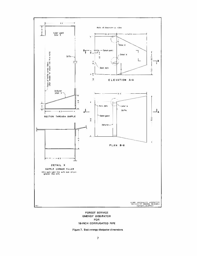
Basic Energy Dissipator
The optimum configuration for each part of the energy dissipater were combined to form a basic energy dissipater. The 1: 1.8 scale model dimensions are shown in Figure 4D.
The recommended basic energy dissipater configuration for an 18-inch corrugated-metal pipe is shown in Figure 7. The baffle and deflector location, upstream dissipater width, downstream wall divergence, and exit lip elevation must be considered as critical dimensions. Other dimensions shown such as splash guard locations, slight slope to the upstream floor, and wall height, may be varied for given locations and discharge requirements. The recommended design, fabricated of sheet metal, is shown installed in the watertight tail box in Figure 8, and in detail in Figure 9.
3
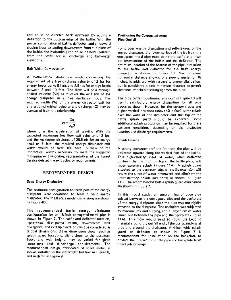
Positioning the Corrugated-metal Pipe Outfall
For proper energy dissipation and self-cleaning of the energy dissipater, the lower surface of the jet from the corrugated-metal pipe must strike the baffle at or near the intersection of the baffle and the deflector. The optimum location of the bottom of the pipe in relation to the baffle and deflector for the basic energy dissipater is shown in Figure 10. The minimum horizontal distance shown, one pipe diameter or 18 inches, is arbitrary with respect to energy dissipation, but is considered a safe minimum distance to permit clearance of debris discharging from the pipe.
The pipe outfall positioning as shown in Figure 10 will permit satisfactory energy dissipation for all pipe slopes as shown. However, for the steeper slopes and higher vertical positions (above 40 inches). some splash over the walls of the dissipater and the top of the baffle splash guard should be expected. Some additional splash protection may be required for these extreme conditions depending on the dissipater location and discharge requirements.
Splash Guards
A strong component of the jet from the pipe will be deflected upward along the vertical face of the baffle. This high-velocity sheet of water, when deflected upstream by the "lip" on top of the baffle plate, will cause excessive splash (Figure 11A). A splash guard attached to the upstream edge of the lip extension will return the sheet of water downward and eliminate the unsatisfactory splash and spray as shown in Figure 11 B. The recommended baffle splash guard dimensions are shown in Figure 7.
In this model study, an annular ring of open area existed between the corrugated pipe and the backplate of the energy dissipater since the pipe was not rigidly attached to the dissipater. The backplate was subjected to random jets and surging, and a large flow of water issued out between the pipe and the backplate (Figure 11A). This flow would tend to scour the bedding material around the outfall end of the corrugated-metal pipe and around the dissipater. A 4-inch-wide splash guard or deflector as shown in Figure 7 is recommended for installation on the backplate to protect the intersection of the pipe and backplate from direct jets or surges.

~ Supply
f)resser coupling swivel
on centerline of pipe trunrnons
0
_..._ 1? - incl". supol~ pipe with
vaned elbows
----- -10'-o" I - r ,a;
, 10-111ch corrugated pipe
-10'-o"-
PLAN
,-Trunnions for corrugated ( prpe
ELEVATION A-A
FOREST SERVICE
ENERGY DISSIPATOR
FOR
18-INCH CORRUGATED PIPE
==='-----'--__,,_j A
US 8 R HYORAUL I CS LABORATORY
DIVISION OF' GENERAL RESEARCH
DENVER,COLORAOO
Figure 3. Model drawing, laboratory installation for 1: 1.8 scale model study.
4

Figure 5. Floor and sidewall study. Photo PX-0-68527
Self-cleaning Capabilities
With the deflector at the bottom of the baffle properly placed, as shown in Figure 7, the jet from the corrugated-metal pipe will be deflected downward along the vertical base of the baffle, and deflected upstream by the deflector to spread laterally and strike the backplate above the floor. A portion of the jet will then be deflected downward to the floor and turned downstream. Thus, the flow on the entire floor of the dissipator will be in the downstream direction and carry with it any loose material on the floor. Random-sized stones were dumped into the pool upstream from the baffle to study the self-cleaning potential of various dissipator designs ( Figure 12A). All of the stones were ejected from the energy dissipator within 1 minute (Figure 128). The design is excellent for self-cleaning of nonfloating debris.
Random lumber scraps were dumped into the pool upstream from the baffle to represent floating debris. These floating particles, in order to be ejected from the energy dissipator, would have to be trapped by the jet from the corrugated-metal pipe, swept under the water surface, and out under the baffle. Many pieces would be repeatedly swept under water only to resurface upstream from the baffle before finally being ejected under the baffle. Twenty-five pieces of scrap lumber dumped into the upstream pool were ejected from the c!issipator in about 45 minutes with the dissipator discharging 10 cfs. The ejection of floating debris, although slow, is satisfactory.
For very low flows, below about 15 percent of maximum, the self-cleaning potential of the dissipator is poor.
6
Figure 6. Flow deflector and upward sloping floor. Note sweepout. Photo PX-0-68528
Slopes Greater than 40 Percent
For pipe slopes greater than 40 percent, the flow from the basic energy dissipator tended to separate from the diverging sidewalls. Large boils appeared near the centerline of the dissipator downstream from the baffle, and eddys or vorticies appeared in the corners at the intersection of the baffle and the diverging sidewalls. The poor flow conditions were more pronounced for steeper pipe slopes.
The addition of two fillers, one on either side of the upstream basin extending from the baffle deflector to splash guard (Figure 13), produced satisfactory flow for all pipe slopes from 40 to 66-2/3 percent. Figure 14 shows the flow conditions for a pipe slope of 40 percent with and without the upstream fillers installed.
For corrugated-metal-pipe slopes less than 40 percent, the fillers tended to concentrate the flow along the diverging sidewalls. The corner fillers (Figure 7), should be used for pipe slopes greater than 40 percent, and should not be used for pipe slopes less than 40 percent. At 40 percent pipe slope the dissipator will operate equally well with or without the corner fillers.
Dissipator Backwater Studies
The dissipator exit lip was placed at the proper elevation to hold sufficient backwater in the exit portion of the dissipator to prevent sweep out. With no backwater downstream from the dissipator, the flow will pass through critical velocity at the exit I ip. Figure

707
..__ _______ 72':...' --------t Boff le for flow spreader
ELEVATION
A. FLOOR STUDY
Floor slopes were vor,ed from + 4.0:1 to -2.s:1, with reverse slopes ot various stations.
The flow from the corrugated pipe did not form o jump, but continued at super - critical velocity across the end sill ( See figure 6 l
i I
I
72 11----------
c:!-_-=--:..-:....,,_-=-.-:.."""-.-,_""""
PLAN
8. SIDE WALL STUDY
Side walls were vertical and symetricol about the centerline.
Best flow was obtained with the sidewalls diverging about 20~
N ....
0 -./'/
I/ // V Boffle varied in
1/. attitude ond position. r rll
~~~ I ~ownstreom floor ,.~ Oeflecto~ Jl slope varied. l varied c:_J __._:, ~,;:::-.,,,..,
Upstream floor ......... ~..=::-_;::-~ ---------level. ~-=--=--=--~
~24" --:.~
ELEVATION
C. BAFFLE AND DEFLECTOR STUDY
A boff le was designed to direct the jet from the corrugated pipe downward. A deflector wos added to return the jet toward the bock wall.
Best action was achieved with o vertical boffel ond o slightly sloping deflector. Best elevation for the deflector wos one pipe diameter above the hOrizontol f looe The boff le position varied with the pipe slope.
Solid lines show optimum conf1gurotion.
PLAN
Dotted lines show unsotis foctony
f=p ~ I
J_J
ELEVATION
D. COMBINED DISSIPATOR SHAPE STUDY
Optimum energy dissipotor dimensions were determined by combining the results of studies A through c.
Self- cleaning potential using both rock ond floating debris wos determined during this study.
USBR HYDRAULICS LABORATORY DIVISION OF GENERAL RESEARCH
DEN VE R1 COLORADO
FOREST SERVICE ENERGY DISSIPATOR
FOR 18-INCH CORRUGATED PIPE
Figure 4. 1 :1.8 scale model dissipator variations. Studies to determine the optimum dimensions for the energy dissipator. All dimensions shown are for the 10-inch laboratory model.
5

Figure 8. Overall view, tvpical energy dissipator installation.
Pipe slope is 66-2/3 percent. Photo PX-0-68542
15A shows the free outflow conditions with the corrugated-metal pipe entering the upstream basin on a 25 percent slope, an entrance energy head of 5 feet, and a dissipator exit velocity (critical) of 5.2 fps. Some added protection would probably be required in the downstream channel although the exit energy head has been reduced to about 1 foot.
The same entrance flow, 25 percent pipe slope and 5 feet of entrance energy head, was discharged through the system, but with sufficient backwater to produce an average exit velocity of 2.2 fps (Figure 15B). With this low exit velocity little scour would be expected downstream from the energy dissipator.
The dissipator exit conditions for a pipe slope of 25 percent, an entrance energy head of 2.8 feet, and a dissipator exit velocity of about 3.3 fps, is shown in Figure 15C. Although this exit velocity is just critical, the exit flow is tranquil and little scour would be expected.
The backwater study indicated that the energy dissipator will contain the hydraulic jump upstream from the baffle for all discharges, regardless of backwater, but the exit, flow from the dissipator will pass through critical velocity at the exit lip unless some type of backwater pool is provided. Where the terrain is such that a backwater pool is not feasible, some channel protection will be needed to protect against scour caused by the critical exit velocity for the maximum design discharge.
Helical Corrugated-metal Pipe
A helical corrugated-metal pipe was installed to discharge into the recommended basic energy
8
Figure 9. Basic energy dissipator, recommended design.
Photo PX-D-68529
dissipator (Figures 2B and 16A). The system was tested with several different pipe slopes, and various Xs-Ys locations as shown on Figure 10. The performance of the energy dissipator was the same with the helical corrugated-metal p ipe as with the annular corrugated-metal pipe. The helical corrugations caused a fin of water to form on the left side at the pipe outfall (Figure 16B); however, except for a slight increase in splash in the upstream basin, the fin did not adversely affect the flow in the energy dissipator. The water in the upstream basin (Figure 16C) and the exit flow from the dissipator was symmetrical for all discharges.
Energy Dissipator Dimension Factors
The recommended basic energy dissipator included the optimum features of all the designs tested for self-cleaning, simplicity, and energy dissipation for an energy head of 5 feet with an 18-inch corrugated-metal pipe flowing full. The basic design produced unsatisfactorily rough flow when the energy head was too great, and unnecessarily tranquil flow when the maximum anticipated energy head was small. A study with the pipe on a slope of 50 percent indicated that the flow from the dissipator was unacceptably rough for an energy head of 8.0 feet ( Figure 17 A), and undesirably rough for an energy head of 7 .2 feet (Figure 17B). These flows produced "boils" and a very rough water surface in the downstream basin which in turn caused uneven flow distribution and relatively high velocity jets to emerge from the dissipator. The flow was acceptable for an energy head of 6.2 feet (Figure 17C), and quite smooth for an energy head of 5.0 feet (Figure 17D). This study indicated that the
757
i-------63----~
T 0
L. Splash guard Detail z
Deflector Detail Y
Baffle
i------6.3-------i
SECTION THROUGH BAFFLE
L .. -, DETAIL X
BAFFLE CORNER FILLER
(One each srdel Use with pipe slopes greater than 40 II.
Br-": r m I I
I I
Note all dimensions in inches
i------33
r Bock plate
ELEVATION A-A
.-Bock plate
Splosh guard
Deflector
,.,-- -,' '
-- - '--Deta,1 x
· Baffle
_t._ __ ._._ ____ _.___. __
PLAN B-B
FOREST SERVICE ENERGY DISSIPATOR
FOR
18-INCH CORRUGATED PIPE
USBR HYDRAULICS LABORATORY DIVISION OF GENERAL RESEARCH
OENVE R, COLORADO
Figure 7. Basic energy dissipator dimensions
7

A. No baffle splash guard. Note excessive splash. Photo PX-D-68536
B. With baffle splash guard. Note jet returning to basin. Photo PX-D-68531
Figure 11. Baffle splash guard.
A. Inserting random sized stones upstream from the basin. Photo P>'·D-68533
B. All stones were swept from the dissipator within 1
minute. Photo PX-D-68534
Figure 12. Dissipator self-cleaning of stone.
10

en LLJ :I: u z
ID >-
LLJ u z ~ I-en C
757
401-----+--------+--
35
30
25
20
51~s----;-.,a;-----;:2~0---7:22=----:2~4----.2Ls ___ 2.ls ____ 3lo ___ J3_2 __ __J34
Defector
..!!! .... '+c
CD
DISTANCE Xa - INCHES
FOREST SERVICE ENERGY DISSIPATOR
FOR 18-INCH CORRUGATED PIPE
Figure 10. Location of invert of discharge end of 18-inch corrugated-metal pipe for various pipe slopes.
9
US BR HYDRAULICS LABORATORY DIVISION OF GENERAL RES,EARCH
DENVER,COLORADO

Figure 13. Baffle corner fillers to be used with pipe slopes greater than 40 percent. Photo PX-D-68552
basic design would operate satisfactorily with a pipe slope of 50 percent and a maximum energy head of about 6.7 feet.
A series of studies were made to determine the maximum acceptable energy head for any pipe slope when used with the basic energy dissipator. The values thus determined were plotted on the discharge-energy head curve for each pipe slope, with the resultant line labeled, "basic dissipator" (Figure 18). This basic energy dissipator for an 18-inch pipe has the dimensions shown in Figure 7.
Using the results for the basic energy dissipator as a model, a family of curves was generated to show the minimum size of energy dissipator required to satisfactorily handle the flow through an 18-inch corrugated-metal pipe for any combination of discharge and pipe slope producing energy heads up to 11 feet (Figure 18).
Thus, the dimension factor for an energy dissipator to be used with an 18-inch corrugated-metal pipe for any given pipe slope and maximum discharge may be determined from Figure 18. The dimensions of the dissipator are determined by applying the interpolated dimension factor, or the next higher factor, to all dimensions shown in Figure 7, and to the Xs-Ys values for the location of the outfall end of the corrugated-metal pipe, Figure 10.
11
A. Without corner fillers. Photo P X-0-68543
B. With corner fillers. Photo PX-D-68544
Figure 14. Operation with a pipe slope of 40 percent-with and without baffle corner fillers.

A. Q = 19.5 cfs He= 5.0 feet S = 25 percent Exit depth = 7 .6
inches Critical exit V = 5.2 fps (No backwater) Photo
PX-D-68532
B. Q = 19.5 cfs He= 5.0 feet S = 25 percent Exit depth= 18
inches Exit velocity = 2.2 fps (with backwater) Photo
PX-D-68530
C. Q = 6.5 cfs He = 2.8 feet S = 25 percent Exit depths= 4 inches Critical exit V = 3.3 fps (No backwater) Photo
PX-D-68535
Figure 15. Dissipator ·exit and backwater conditions.
12
A. Helical corrugated-metal pipe in the model. Photo
PX-D-68548
B. Note water fin on left side of exit flow. Photo
PX-D-68554
C. Note uniformity in upstream basin. Photo PX-D-68550
Figure 16. Helical corrugated-metal-pipe studies.

A. Q = 21 .5 cfs, He = 8.0 feet, S = 50 percent. Note unacceptably rough flow. Photo PX-D-68537
C. Q = 13.0 cfs, He = 6.2 feet, S = 50 percent. Acceptable flow. Photo PX-D-68539
B. Q = 17.4 cfs, He Jl .2 feet, S = 50 percent. Note surges downstream from dissipator. Photo PX-D-68538
D. Q = 8.7 cfs, He = 5.0 feet, S = 50 percent. Relatively smooth flow. Photo PX-D-68540
Figure 17. Acceptable and unacceptable flow. Note wave action on backwall of box.
Example to dimension an energy dissipator for an 18-inch corrugated-metal-pipe underdrain on a 30 percent pipe slope and a maximum discharge of 5.0 cfs: From Figure 18, the dimension factor is 0.56. Modify all I in ear dimensions shown in Figure 7, Basic Energy Dissipator, and the Xs-Ys values in Figure 10 by the factor 0.56.
As a check on the application of the dimension factor chart, a 1: 1.8 scale model of the energy dissipator for the above example was constructed and installed in the laboratory test box ( Figures 19 and 20A). This comparatively small energy dissipator was tested for several pipe slopes and a range of discharges up to 5 cfs (Figure 20B). Energy dissipation was excellent for all pipe slopes and discharges tested.
Figures 7 and 18 are applicable without reservation for energy di ssipators to be used with 18-inch corrugated-metal pipe underdrains.
Pipes other than 18 inches
All dimensions and values in this report may be recomputed to generate parameters for
13
corrugated-metal-pipe underdrains of sizes other than 18 inches. Values of the parameters for an 18-inch corrugated-metal pipe in Figures 7, 10, and 18 may be multiplied by a ratio "N" to determine companion parameters for the desired pipe size.
p N=-
18
P = nominal corrugated-metal-pipe size (inches)
Parameter
Linear measurements y2
Energy head (2g + depth)
Discharge
Pipe slope
Multiplier
N
The new charts generated from the computations could be applied to any desired corrugated-metal-pipe size. The author feels that the energy dissipator developed here should not be used for corrugated-metal-pipe sizes larger than 36 inches without further model studies.

.,; ,..: ,.;
.... "' a: <[ :,: u
"' c
'"
45
40
35
30
25
20
15
10
5
0 0 2 3 4 6 7 8 9 10 II
v• 18- INCH PIPE, ENERGY HEAD, FEET OF WATER (He= 2g + FLOW DEPTH)
NOTES For pipe slopes greoter than
40 % • deflector fillers must be used to achieve proper flow distribution ond dissipotor se If cleaning capabilities.
Far 40 % pipe slope the dissipater operates equally well with or without fillers.
Dimension factor line is the upper limit of sotisfoctory operation for the discharge and pipe slope shown .
FOREST SERVICE
ENERGY DISSIPATOR
FOR
18-INCH CORRUGATED PIPE
E ,ample· For an 18- inch corrugated pipe installed on o 30 % slope ond discharging 15 cfs. the dimension of the bosic energy dissipotor, Figure 7, should be modified by the factor 0.87 .
USBR HYDRAULICS LABORATORY DIVISION OF GENERAL RESEARCH
DENVER,OOLORAOO
Figure 18. Dimension Factor Chart for 18-inch corrugated pipe.
14

A. Energy dissipator in the watertight box. Photo PX-0-68545
B. Q = 5.0 cfs; He PX-0-68546
2.1 feet; S
Figure 20. Tests with an energy dissipator reduced by a factor of 0.56.
16
20 percent. Photo

Elements for design: /IS-inch corrugated pipe Underdroin- is-inch corrugated pipe.
,-;---.......i__ Slope ~ 301. Underdroin Slope - 301. / \ -- (Other slopes tested) Maximum dischorge-5cfs / I ----- Dimension factor -0.56 ( From Figure 18) I I ---I I --- Note: All dimensions in inches I // 1 (Converted to prototype) v I
/ I 18.9-----------26.5-------01 / I 4~
/ -,----t----+'---~+--=--i--1 I I
'-----
I I I I I ------ I
I I
-~q-15.5
l TL .. ..
l ~-----·--+---!-------....
I \ \ I \ \ I I I \ I I \ I \ \; ~ I I ~ I
I I I I I / \ I \ I '-------- - ___ __/
ELEVATION
t "! <O
,., ci ...
i------lS.9-------+------ 26.5 --------~1 i------------ 45.4 ---------------·
PLAN
FOREST SERVICE ENERGY DISSIPATOR
FOR 18-INCH CORRUGATED PIPE
USBR HYDRAULICS LABORATORY DIVISION OF GENERAL RESEARCH
DENVER, COLORADO
Figure 19. Energy dissipator for a dimension factor of 0.56.
15
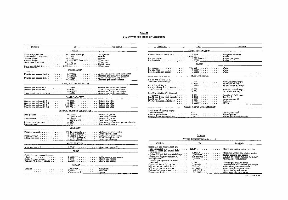
Multiply
Grains (1/7, 000 lb) , . • Troy owices (480 grains), Ounces (avdp). . ••
f:rNo~"sv1tooo 1b,: Long tons (2,240 lb):
Pounds per square inch
Pounds per square foot
Ounces per cubic inch . . . Pounds per cubic foot . . •
Tons Uong) per cubic yard :
Ounces per gallon (U, S, ) Ounces per gallon (U. K. ) Pounds per gallon (U. S, ) Pounds per gallon (U, K,)
Inch-powids
Foot-pounds
toot-pounds pe~ !~ch Ounce-inches. . • •
Feet per second.
Feet per yea:r. . Miles per hour .
Feet per second2 .
Cubic feet per seconc! (second-feet) .••..•....
Cubic feet per minute . . . Gallons (U.S.) pe, minute •
Pounds,
By
MASS
64, 79891 (emctiy) 31. 1035. • . . . 28. 3495 ...... . 0. 45369237 (exactly).
907.185 ..... . 0. 007185 •••. • 1,016.05 .••••.
FORCE AREA
0. 070307. 0. 689476. 4. 88243 •
47. 8803 ••
MASS/VOLUME (DENSITY)
1. 72999 . 16. 0185 . 0. 0160185 1. 32894
MASS/CAPACITY
~- 4893. 6. 2362.
119. 829 . 99. 779 .
BENDING MOMENT OR TORQUE
VELOCITY
30. 48 (exactly). . . 0. 3048 (emctly) • . 0, 965873 X 10-6* , 1, 609344 (exactly). 0. 44704 (emcUyt .
ACCELERATION*
0,30<18* ..
FLOW
o. 028317* o. 4719 • 0.06309 .
FORCE*
0. 453592* ... u:~rx w-5• :
Table II
QUANTITIES AND UNITS OF MECHANICS
Milligrams Grams Grams Kilograms Kilograms Metric tons Kilograms
To obtain
Kilograms per square centimeter Newtons per square cenUmeter Kilograms per square meter Newtons per square meter ·
Grams per cµbic centimeter Kilograms per cubic meter Grams per cubic centimeter Grams per cubic centimeter
Grams per liter Grams per llter Grams per liter Grams per liter
Meter-kilograms Centimeter-dynes Meter-kilograms Centimeter-dynes Centimeter-kilograms per centimeter Gram-centimeters
Centimeters per second Meters per second Centimeters per second Kilometers per hour Meters per second
Meters per second2
Cubic meters per second Liters per second Liters per second
Kilograms Newtons Dynes
Multiply
Br!t!sh thermal units (Btu) •
Btu per pound. Foot-pounds . . . . . . .
Horsepower . . . . . . Btu per hour • • • • • • Foot-pounds per second .
Btu in. /hr ft2 deg F (k, thermal conductivity)
Btu ft/hr ft2 deg F • • : : : Btu/hr fl2 deg F (C, thermal
conductance) . . . . . . .
Deg F hr tt2/Bt~ (R,' the;m'a.J.· resistance} . . . . . . . . .
Btu/lb deg F (c, heat capacity) •
~~1i! 'l;le;m'a! · diff~s1'v1iy>°
Grains/hr tt2 (water vapor transmission) . . . . . .
Perms (permeance) . . . . Perm-inches (permeability)
Multiply
Cubic feet per square foot per day (seepage) • • . • . . •
Pound-seconds per square foot (v!scos!ly) • • . • . • • • . .
Square feet per second (viscosity}. Fahrenhe!l degrees (change)•. Volts per ml!. . . . . . • .
L~:i~!s)r. s~~~ ~o~ ~fo~t~ Ohm-circular mils per foot M!lllcur!es per cubic foot • M!ll!amps per square foot • Gallons per square yard , Pounds per inch.
By
WORK AND ENERGY*
. 0. 252* • 1,055.06 .••.
2. 326 (exactly) 1.35582• ••
POWER
745. 700 ••. 0. 293071 .• 1. 35582 . .
HEAT TRANSFER
1. 442 . 0. 1240. 1. 4880•
0.568 4.882
1. 761 4.1868 1.000• o. 2581 • 0.09290*.
WATER VAPOR TRANSMISSION
16. 7 0. 659 1. 67
Table III
OTHER QUANTITIES AND UNITS
By
304. 8• .••
4. 8824* .. 0. 092903• •. 5/9 exactly . 0. 03937.
10. 764. . 0. 001662 36. 3147* 10. 7639* .
4. 527219• 0.17858•.
To obtain
Kilogram calories Joules Joules per gram Joules
Watts Watts Watts
M!ll!watts/cm deg C
~~ ~~~/h°; ~H ~g C
M1111watts/cm2 deg C Kg cal/hr mZ deg C
Deg C cm2 /mlll!watt J/g deg C Cal/gram deg C cw2/sec M /hr
Grams/24 hr m2 Metric perms Metric perm-centimeters
To obtain
Liters per square meter per day
Kilogram second per square meter Square meters per second Celsius or Kelvin degrees (change)• Kilovolts per millimeter
Lumens per square meter Ohm-square millimeters per meter Mlllicuries per cubic meter Milliamps per square meter Liters per square meter Kilograms per centimeter
GPO 834-341
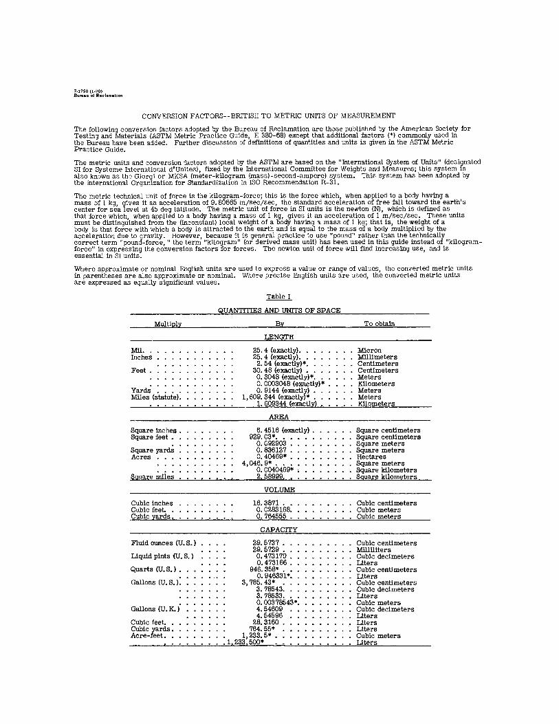
7•1750 (1•70) Bureau of Reclamation
CONVERSION FACTORS--BRITISH TO METRIC UNITS OF MEASUREMENT
The following conversion factors adopted 'oy the Bureau of Reclamation are those published by the American Society for Testin;i and Materials (ASTM Metric Practice Guide, E 380-68) except that additional factors (*) commonly u.sed in the Bureau have been a::lded. Further discussion of definitions of quan~ities and units is given in the ASTM Metric Pra::tice Guide.
The metric units and conversion factors adopted by the ASTM are based on the "International 8'Jstem of Units" (designated SI for Systeme International d'Unites), fixed by the International Committee for Weights and Measures; this system is also known as the Giorgi or MKSA (meter-kilogram (mass)-second-ampere) system. This system has been adopted by the International Organization for Standardization in ISO Recommendation R-31.
The metric technical unit of force is the kilogram-force; this is the force which, when applied to a bo::ly having a mass of 1 kg, gives it an acceleration of 9. 80665 m/sec/sec, the standard acceleration of free fall toward the earth's center for sea level at 45 deg latitude. The metric unit of force in SI units is the newton (N}, which is defined as that force which, when applied to a body having a mass of 1 kg, gives it an acceleration of 1 m/sec/sec. These units must be distinguished from the (in::onstant) local weight of a body having a mass of 1 kg; that is, the weight of a body is that force with which a body is attracted to the earth an::! is equal to the mass of a body multiplied by the acceleration due to gravity. However, because it is general practice to use "pound" rather than the technically correct term "pound-force," the term "kilogram" (or derived mass unit) has been used in this guide instead of "kilogramforce" in expressing the conversion factors for forces. The newton unit of force will find increasing use, an:i is essential in SI units.
Where approximate or nominal English units are used to express a value or range of values, the converted metric units in parentheses are also approximate or nominal. Where precise English units are ased, the converted metric units are expressed as equally significant values.
Table I
QUANTITIES AND UNITS OF SPACE
Multiply By To obtain
LENGTH
Mil. 25. 4 (exactly) •• Micron Inches 25. 4 (exactly) .• Milllmeters
2. 54 (exactly)* •• Centimeters Feet. 30. 48 (exactly) • . Centimeters
0. 3048 (exactly)* .• Meters 0. 0003048 (exactly)* Kilometers
Yards 0. 9144 (exactlf,) • • Meters Miles (s°taiute): 1,609. 344 (exactly * • . Meters .. 1. 609344 (exactly) • Kilometers
AREA
Square inches. 6. 4516 (exactly) • Square centimeters Square feet • 929.03* .••••• Square centimeters
0.092903 • Square meters Square yards 0. 836127 • Square meters Acres 0.40469* • Hectares
4,046. 9*. Square meters o. 0040469* • Square kilometers
Square miles 2.58999. .. Square kilometers
VOLUME
Cubic inches 16.3871 • Cubic centimeters Cubic feet. 0. 0283168: • Cubic meters Cubic yards • 0.764555. Cubic meters
CAPACITY
Fluid ounces (U.S. ) 29.5737 • Cubic centimeters 29.5729. Milliliters
Liquid pints CU. S. ) 0.473179 : Cubic decimeters 0.473166. Llters
Quarts (U.S.) • 946.358* • Cubic centimeters
Gallons (U.S. i: 0. 946331*: Llters 3,785. 43* • Cubic centimeters
3. 78543. -Cubic decimeters 3. 78533 ••• Llters
Gallons (U. K.) o. 00378543*. Cubic meters 4.54609 Cubic decimeters 4.54596 Liters
Cubic feet. 28.3160 Liters Cubic yards • 764.55* Liters Acre-feet. • 1,233. 5* • Cubic meters
.1, 233.500* Liters

REC-ERC-71-10 Colgate, D HYDRAULIC MODEL STUDIES OF CORRUGATED-METAL PIPE UNDERDRAIN ENERGY DISSIPATORS FOR FOREST SERVICE, UNITED STATES DEPARTMENT OF AGRICULTURE '. Bur Reclam Rep REC-ERC-71-10, Div Gen 'Res, Jan 1971. Bureau of Reclamation, Denver, 16p, 20 fig
DESCRIPTORS-/ *maintenance/ design data/ optimum design/ scour/ design/ backfill/ *culverts/ small structures/ backwater/ hydraulic jump/ *model tests/ *hydraulic conduits/ hydraulic models/ *outflows/ jets/ *erosion control/ subcritical flow/ *energy dissipation/ underdrains/ laboratory tests IDENTI Fl ERS-/ Forest Service/ corrugated-metal pipe/ self-cleaning
REC-ERC-71-10 Colgate, D HYDRAULIC MODEL STUDIES OF CORRUGATED-METAL PIPE UNDERDRAIN ENERGY DISSIPATORS FOR FOREST SERVICE, UNITED STATES DEPARTMENT OF AGRICULTURE Bur Reclam Rep REC-ERC-71-10, Div Gen Res, Jan 1971. Bureau of Reclamation, Denver,
· 16p, 20 fig
DESCRIPTORS-/ *maintenance/ design data/ optimum design/ scour/ design/ backfill/ *culverts/ small structures/ backwater/ hydraulic jump/ *model tests/ *hydraulic conduits/ hydraulic models/ *outflows/ jets/ *erosion control/ subcritical flow/ *energy dissi'pation/ underdrains/ laboratory tests IDENTIFIERS-/ Forest Service/ corrugated-metal pipe/ self-cleaning
REC-ERC-71-10 Colgate, D
HYDRAULIC MODEL STUDIES OF CORRUGATED-METAL PIPE UNDERDRAIN ENERGY DISSIPATORS FOR FOREST SERVICE, UNITED STATES DEPARTMENT OF AGRICULTURE
Bur Reclam Rep REC-ERC-71-10, Div Gen Res, Jan 1971. Bureau of Reclamation, Denver, 16p, 20 fig
DESCRIPTORS-/ *maintenance/ design data/ optimum design/ scour/ design/ backfill/ *culverts/ small structures/ backwater/ hydraulic jump/ *model tests/ *hydraulic _conduits/ hydraulic models/ *outflows/ jets/ *erosion control/ subcritical flow/ *energy dissipation/ underdrains/ laboratory tests IDENTIFIERS-/ Forest Service/ corrugated-metal pipe/ self-cleaning
REC-ERC-71-10 Colgate, D HYDRAULIC MODEL STUDIES OF CORRUGATED-METAL PIPE UNDERDRAIN ENERGY DI_SSIPATORS FOR FOREST SERVICE, UNITED STATES DEPARTMENT OF AGRICULTURE Bur Reclam Rep REC-ERC-71-10, Div Gen Res, Jan 1971. Bureau of Reclamation, Denver, 16p, 20 fig
DESCRIPTORS-/ *maintenance/ design data/ optimum design/ scour/ design/ backfill/ *culverts/ small structures/ backwater/ hydraulic jump/ *model tests/ *hydraulic conduits/ hydraulic models/ *outflows/ jets/ *erosion control/ subcritical flow/ *energy dissipation/ underdrains/ laboratory tests IDENTIFIERS-/ Forest Service/ corrugated-metal pipe/ self-cleaning

' •••••••••••••••••••••••••••••••••••••••••••••••••••••••••••••••••••••••••••••• • •••• : ••••••••••••••••••••••••••••••••• • •••••••••••••• I ••••••••••••••••••••••••••••••••••
ABSTRACT
The discharge from small corrugated-metal pipe underdrains tends to erode the bedding material at the underdrain outfall. Protection methods used in the past have been inadequate, and the necessary yearly maintenance and repairs of the underdrain outfall areas are time-consuming and expensive. Hydraulic model studies were used to develop an energy dissipator that would prevent scour at the outfall end of an 18-in. corrugated-metal pipe underdrain. The dissipator is fabricated of lightweight sheet metal, and is easily transported to, and assembled at, the site: The dissipator may be used with any pipe slope between O and 66-2/3%, and will not sweep out at discharges up to that of a pipe flowing full (not under pressure). The dissipator is self-cleaning for either rock or floating debris. The report includes charts for energy dissipator size variations for reduced maximum discharge requirements, and formulas for dimension requirements for dissipators to be used with corrugated-metal pipe sizes other than 18 in.
o••••-•••••••••••••••••••••••••••••••••• ••• •••••.•••• •••• • • • • •• ••••• • • ••• • •• ••• •• ••• ••:••••••• • •••••• ••••••••• • •• •• • • ••• • • • ••• • • ••••• •••••••••••• • •••••••••••• ••••••••••••• .
ABSTRACT
The ~ischarge from sm_all corrugated-metal pipe underdrains tends to erode the bedding material at the underdrain outfall. Protection methods used in the past have been inadequate, and the necessary yearly maintenance and repairs of the underdrain outfall areas are ti_m~-consuming and expensive. Hydraulic model studies were used to develop an energy d1ss1pator that would prevent scour at the outfall end of an 18-in. corrugated-metal pipe underdrain. The dissipator i_s fabricated of lightweight sheet metal, and is easily transported to, and assembled at, the site. The dissipator may be used with any pipe slope between o and 66-2/3%, and will not sweep out at discharges up to that_ of a pipe flowing full (not under pressure). The dissipator is self-cleaning for either rock or floating debris. The report includes charts for ene~gy dissipator size variations for reduced maximum discharge requirements, and formulas for dimension requirements for dissipators to be used with corrugated-metal pipe sizes other than 18 in.
ABSTRACT
The discharge from small corrugated-metal pipe underdrains tends to erode the bedding material at the underdrain outfall. Protection methods used in the past have been inadequate, and the necessary yearly maintenance and repairs of the underdrain outfall areas are time-consuming and expensive. Hydraulic model studies were used to develop an energy dissipator that would prevent scour at the outfall end of an 18-in. corrugated-metal pipe underdrain. The dissipator is fabricated of lightweight sheet metal, and is easily transported to, and assembled at, the site: The dissipator may be used with any pipe slope between O and 66-2/3%, and will not sweep out at discharges up to that of a pipe flowing full (not under pressure). The dissipator is self-cleaning for either rock or floating debris. The report includes charts for energy dissipator size variations for reduced maximum discharge requirements, and formulas for dimension requirements for dissipators to be used with corrugated-metal pipe sizes other than 18 in.
