i!11. nu 0m - dtic
TRANSCRIPT

I!11. nu 0m
DOo/FAoT-_9 Flam m ability, Sm oke, and DryFAA Technical Center Arc Tracking Tests of AircraftAtlantic City International Airport
N.J, 08405 Electrical W ire Insulations
C\I Patricia Cahill
July 1989
Final Report
This document is available to the U.S. publicthrough the National Technical InformationService, Springfield, Virginia 22161.
DTICS ELECTE_
U S Depoartment of Transportation BFederol Aviation Administraton B
89 11 07 042

NOTICE
This document is disseminated under the sponsorshipof the U.S. Department of Transportation in the interest ofInformation exchange. The United States Governmentassumes no liability for the contents or use thereof.
The United States Government does not endorseproducts or manufacturers. Trade or manufacturers'names appear herein solely because they are consideredessential to the objective of this report.

Technical Report Documentation Page
1. Report No. 2 Go~ernmenl Accession No, 3. Recipient s Catalog No
DOT/FAA/CT-89/214. Ttle and S.,btle S. Report Date
July 1989
FLAMMABILITY, SMOKE AND DRY ARC TRACKIN(I TFSTS OF 6. Perforing Orgon,zion Code
AIRCRAFT FLECTR1CAL. WIRE INSULATIONS
8. Performing Organization Report No.
7. Author'% s)
Patricd'2 L. Cahill DOT/FAA/CT-89/21
9. Performng Organization Name and Address 10 Work Un., No (TRAIS)
Federal Aviation Administration ,
Technical Center I . Contract Giant No.
Atlantic City International Airport, NJ 0840513 Type of Report ana Period Coertd
12. Sponsoring Agency Nome and Address
U.S. Department of Transportation Final Report
Federal Aviation Administration
Technical Center 1 Sp"osor,g Agecy Code
Atlantic CIy 7T1teinatio.al Airport, NJ 08405
15. Supplementary Notes
16. Abstract Although three different laboratory-scale tests were ev.luated In this wire
program, only the sixty-degree test is currently required by the Federal Aviat,on
Administration (FAA). All test specimens with the exception of MTL-W-5086/1-?-C
nylon passed this test with average burn lengths within the 3-inch rmsximmm andno flame time. The MIL-W-5086/1 samples marginally passed the 30-second flametiae, and the average burn length was greater than the 3-inch maximum specified
in the FAR.
The smoke test method used in this program called for a straight pilot burnerwhen testing insulated conductor specimens. However, data for a multidirectional
pilot burner were also included in this report, T rgc ,-ariaticor.: - -s 0cccrred
between the two burners for ETFE constructions at both the 5- and 20-minute testpoints. The MIL-W-81381/12 aromatic polyimide and the conposite construction(Teflon/polyimide/Teflon or TPT) showed no appreciable difference in D, between
the two burner types. Moreover, test duration did not affect smoke generationfor these two samples.
A direct correlaticn can be seen between dry arc tracking tests and wet arc
tracking tests (DOT/FAA/CT-88/4). The halogenated polymers formed no conductivechars upon thermal decomposition and, therefore, no dry arc tracking. The MIL-W-81381/12 aromatic polyimide samples formed a conductive char upon thermaldegradation, and severe arc tracking occurred. Extensive damage to all wires inthe bundle occurred due to arc tracking propagation upon circuit breakeiresetting. The TPT composite construction performed well. No dry arc trackingwas evident. This construction behaved similarly to P halop.enated polymor 4nthis respect.
17. Key Word, 18. D,ssr,bution Statement
Drv Arc Trackling Document is available to the public
Sixty-degree Flammability Tests through the National Technical
Flectrical Wire TInsulations Information Service. Springfield,
qmoke Test Virginia 2216]
19. Security Classf. (of this report) 20. Security Coo (of th. r-;.' '2. No ar Pages 2. Prcej
ic In qc i f le d [ In c ] ass f i e d 2 NO. o2
Form DOT F 1700.7 (8-72) Reproduction of compl-rn, page cutforized
B

TABLE OF CONTENTS
Page
EXECUTIVE SUMARY v
INTRODUCTION I
Purpose
Background
DISCUSSION 1
Test Description 1
Test Procedures 1
Test Samples 1
Test Results 3
SUMMARY 4
CONCLUSIONS 5
APPENDIX
A - Sixty-degree Test
Aooession For
NTIS GRA&I
DTIC TAB
UnFUMounced 5
By0jDtrib u ton/
uA_v~ilabilitY Codes
Jut / sotO /
ia
Dist Speial

LIST OF ILLUSTRATIONS
Figure Page
I Test Device 6
2 TPT Photograph 15
3 MIL-W-81381/12 Photograph 15
4 MIL-W-22759/16 Photograph 16
5 MIL-W-5086/1 Photograph 16
6 MIL-W-22759/41 Photograph 17
7 Lab Sample Photograph 17
LIST OF TABLES
Table Page
1 Test Sample Summary - Sixty-degree Test 7
2 Test Sample Summary - Smoke Test 8
3 Test Sample Summary - Dry Arc Tracking Test - TPT 9
4 Test Sample Summary - Dry Arc Tracking Test - MIL-W-81381/12 10
5 Test Sample Summary - Dry Arc Tracking Test - MIL-W-22759/16 11
6 Test Sample Summary - Dry Arc Tracking Test - MIL-W-5086/1 12
7 Test Sample Summary - Dry Arc Tracking Test - MIL-W-22759/41 13
8 Test Sample Summary - Dry Arc Tracking Test - Laboratory 14
Sample
iv
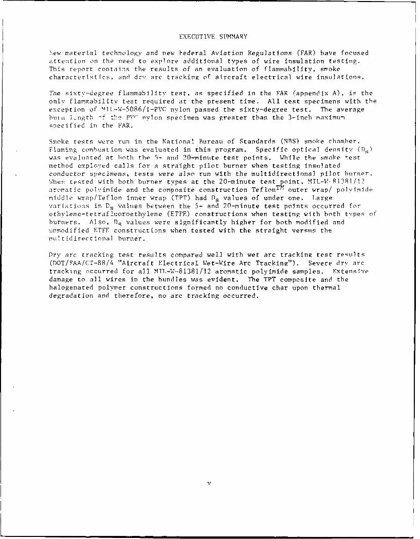
EXECUTIVE SUMMARY
New material technology and new }ederal Aviation Regulations (FAR) have focused
attention on the need to explore additional types of wire insulation testing.This report contains the results of an evaluation of flammability, smoke
characteristics, and dry arc tracking of aircraft electrical wire insulations.
The sixty-degree flammability test, as specified in the FAR (appendix A), is the
only flammability test required at the present time. All test specimens with theexception of NIL-W-5086/l-PVC nylon passed the sixty-degree test. The averagebut il ]ngth -f th pvr nylon specimen was greater than the 3-inch maximum
specified in the FAR.
Smoke tests were run in the National Bureau of Standards (NBS) smoke chamber.Flaming combustion was evaluated in this program. Specific optical density O s )
was evalunted at both the 5- and 20-minute test points. While the smoke test
method employed calls for a straight pilot burner when testing insulatedconductor specimens, tests were also run with the multidirectional pilot burner.Nhen tested with both burner types at the 20-minute test point, MIL-W-91381/12aromatic polyimide and the composite construction TeflonTM outer wrap/ polyimide
middle wrap/Teflon inner wrap (TPT) had D. values of under one. Largevariations in D s values between the 5- and 20-minute test points occurred forethvlene-tetrafluoroethylene (ETFE) constructions when testing with both types of
burners. Also, D. values were significantly higher for both modified and
unmodified ETFE constructions when tested with the straight versus the
multidirectional burner.
Dry arc tracking test results compared well with wet arc tracking test results(DOT/FAA/CT-88/4 "Aircraft Electrical Wet-Wire Arc Tracking"). Severe dry arc
tracking occurred for all MIL-W-81381/12 aromatic polyimide samples. Extensivedamage to all wires in the bundles was evident. The TPT composite and thehalogenated polymer constructions formed no conductive char upon thermaldegradation and therefore, no arc tracking occurred.
v

INTRODUCTION
PURPOSE.
The objective of this project was to evaluate flammability, smokecharacteristics, and dry arc tracking resistance of aircraft electrical wireinsulations.
BACKGROUND.
At the present time, the only flammability test required for wire insulation isthe sixty-degree test in compliance with Part 25.1359(d) in Appendix F of theFederal Aviation Regulations (FAR). With the advent of new material technologyand new Federal Aviation Administration (FAA) regulations requiring morestringent flammability and smoke testing of aircraft materials, a need foradditional types of wire insulation testing would seem apparent. Two candidatesfor these additional types of wire insulation testing are a smoke test and a dryarc tracking test.
DISCUSSION
TEST DESCRIPTIONS.
9IXTY-DEGREE TEST. The sixty-degree test evaluates (1) ease of ignition, (2)flame propagation, (3) self-extinguishment time upon flame removal, and (4) flametime of drippings. This test has shown itself to be a quick and effective meansfor screening flammability characteristics of wire insulations.
SMOKE TEST. In recent years, increased attention has been focused on the effectsof smoke emanating from burning aircraft materials. In the confined environmentof an aircraft cabin, it is imperative that smoke emission from all sources beminimized as the smoke may cause passenger panic and obscure exits and routes ofescape. Transport category aircraft contain miles of wiring, therefore, limitingthe smoke produced by wiring insulation in a fire would help to minimize theeffects discussed above.
DRY ARC TRACKING TEST. One problem that the United States Navy has encounteredis the phenomenon of wet arc tracking (DOT/FAA/CT-88/4 "Aircraft Electrical Wet-Wire Arc Tracking"). While wet arc tracking is not a common occurrence incommercial aircraft, a dry arc tracking test would be beneficial in that a wireinsulation's tendency to form a char upon thermal degradation could becharacterized. Thermal degradation is primarily initiated by the extremely hightemperature of an electrical arc. Upon thermal breakdown, a wire insulation will(1) decompose and give off gaseous byproducts or (2) form a char which may beconductive. If the initial arc were to trip one or more circuit breakers,resetting of the breakers may result in severe damage propagation to the wirebundle if a conductive char is present. This phenomenon is known as arc
tracking.
TEST PROCEDURES.
SIXTY-DEGREE TEST. The sixty-degree test was performed in accordance with theprocedure specified in Appendix F of Part 25 of the FAR. Refer to appendix A forthe test description.
1

SMOKE TEST. The smoke test was performed in accordance with the procedure
specified in the American Society for Testing and Materials (ASTM) Standards F14titled, "Standard Test Method for Specific Optical Density of Smoke CenerateA bySolid Materials for Aerospace Applications." Refer to this method for the testdescription. Only the flaming condition was evaluatpA in this program. Whilethis procedure calls for a straight pilot burner when testing insulatedconductor specimens, data for a multidirectlonal pilot burner is included In thetest results.
DRY ARC TRACKING TEST. This test was performed using a seven-wire bundle cut toa length of 14 inches. Insulation of 3/16 inches was stripped from both ends ofeach wire. The wires were tied in a six-around-one configuration using anappropriate tying material (waxed linen lacing cord, nylon lacing cord, plastictie-wraps, etc.) with the tie nearest the end of the bundle, 1/4 inch back on theinsulation from the stripped wire ends. A second tie was made around the bundle2 inches farther back from the first tie. The tie material used was the waxedlinen lacing cord.
After the bundle was tied, all the exposed wire ends on one side of the bundle
were splayed out such that the strands of each conductor were intermingled withthose of adjacent conductors. A small amount of finely powdered conductivegraphite was applied to the splayed wire ends to insure that an arc was struck.The bundle was then supported horizontally in a lab stand using two clamps
approximately 8 inches apart.
Power was supplied through a 115/220-volt, 400-cycle motor-generator rated at18.75 kVA. It was located approximately 50 feet from the test stand and waswired to the test bench through a 75- and a 20-ampere circuit breaker inside thegenerator control box. Individual fuses in a separate fuse box for each phase, aheavy duty manual on-off switch at the test bench, and seven 7-1/2 ampereKlixonTM aircraft circuit breakers in a box on the test bench completed theelectrical configuration.
Two breakers were connected to phase "A," two to phase "B," two to phase "C," andone to neutral. All seven test leads had alligator clips on the ends tofacilitate connecting to the wires being tested. The test leads were randomly
connected to the seven wires in the test bundle. A 3- by 4-foot shield wasplaced in front of the test setup to protect personnel from the molten metal andburned insulation thrown off when the test arc occurred. Figure I is aphotograph of the test device.
The test arc was initiated by closing the heavy duty manual switch at the testbench. After the initial arc was struck, only one attempt was made to reset anyopen circuit breakers. Ten tests were run on each wire sample.
TFST SAMPL.ES.
Six wire types were evaluated in this test program. Four of these constructions
are currently inservice wires-
MIL-W-81381/12 - KaptonTM aromatic polyimide - liquid H-301 topcoatMIL-W-22759/41 - Extruded radiation cross-linked ETFEMIL-W-22759/16 - Extruded TefzelTM (FTFE)
MIL-W-5086/1 - PVC nylon
2

The fifth wire type evaluated was an experimental composite constructionconsisting of a TeflonTM outer wrap/polyimide middle wrap/Teflon inner wrap(TPT). The sixth wire type was a proprietary cross-linked irradiated ethylene-
tetrafluoroethvlene (FTFE). All test specimens were American Wire Gauge (AWG) 20interconnect w-re;.
TEST RESLLTS.
SIXTY-DEGREE TEST. Table I summarizes the results of the sixty-degree test.
The average burn length of all samples, with the exception of MIL-W-5086/1 waswithin the 3-inch maximum specified in the FAR. The average burn length of theMIL-W-5086/1 samples was 5.1 inches, which exceeds the 3-inch maximum.
No flaTie time after removal of the flame source was recorded for the samples,
with the exception of MIL-W-5086/1. The avezage flame rime for MIL-W-5086/l was26 seconds. This is within the 30-second time limit defined in the FAR. No
drippings from any of the test samples were detected.
SMOKE TEST. Table 2 summarizes the results of the smoke tests performed on the
wire test samples. Ihile the ASTh method employed specifies a straight flameburner, some laboratories use the multidirectional burner. Therefore, data for
both burners are presented. From table 2, the specific optical density (Ds ) forTPT and MIL-W-81381/12 does not significantly vary when comparing 5-minute with20-minute values for both types of burners. Both TPT and MIL-W-81381/12
produced extremely sm.iL amounts of smoke. In both cases, Ds values were underone. When tested with both burner types, MIL-W-5086/1 generated large quantities
of dark smoke. Specific optical density values reached the highest number
capable of computer generation at the 5-minute test interval (D,=776.5)
therefore, samples were not run for 20 minutes. The MIL-W-22759/16 samplesshowed a large variation in D s values between the 5- and 20-minute test intervals
for both burners. Moreover, significant differences in Ds values occurredbetween the two different burners at both the 5- and 20-minute test points withthe straight burner producing higher D. values.
The MIL-W-22759/41 test samples also showed a noticeable difference in D. values
between the 5- and 20-minute test points. This difference occurred with bothburner types: again, the straight burner producing higher Ds values than themultidirectional burner. The extruded rad~ation crosslinked ETFE laboratory
samples produced large quantities of smoke. At the 20-minute test point, D.alues for both burners were 775.0. At the 5-minute test point, the D s was
significantly higher with the straight burner (55.5) than the multidirectional
burner (7.7).
DRY ARC TRACKING TEST. Tables 3 through 8 summarize the results of the dry arc
tracking tests and figures 2 through 7 are photographs of the wire bundles aftertesting. Table 3 presents the data for the only composite construction among thetest specimens. This wire sample incorporated a Teflon outer wrap/polyimide
middle wrap/Teflon inner wrap. No dry are tracking was found. The initial arcs
struck were all moderate in severity. Figure 2 shows the TPT wire bundles aftertesting. Note the appearance of welds and some tube effects (i.e., vaporization
of conductor with insulation material remaining). No evidence of carbonizationwas found on the wire insulation. Data on MIL-W-81381/12 (aromatic polyimide)
samples are presented in table 4. All initial arcs were massive in severity and
caused multiple circuit breakers to trip. Carbonization of the polyimide due to
3

the temperature of the initial arc occurred each time. Upon resetting of thecircuit breakers, severe re-arcing took place resulting in more insulationdegradation. The polyimide samples are shown in figure 3. Tables 5, 6, and 7summarize arc tr;ocking data on three halogenated polymers. All insulationsystems are currently in service. Initial arcs were mild to moderate for allthree sets of samples. No dry arc tracking was found for any of the testspecimens. Upon resetting of tripped circuit breakers, tables 5, 6, and 7 showthat all breakers either stayed in, retripped immediately, or resulted in a smallarc restrike followed by a circuit breaker retrip. Figures 4, 5, and 6 show thewire bundles after testing. Note the similar appearance of all three specimenswith the welds and tube effects. Minimal insulation damage is seen for allsamples. Table 8 presents the data on the laboratory sample of extrudedradiation crosslinked ETFE. Five tests were performed due to a shortage ofsample wire. Initial arcs were mild to moderate. No dry arc tracking was found.Upon resetting of tripped circuit breakers all breakers retripped immediately or
stayed in. The wire bundles are shown in figure 7.
S LiARY
Although three different laboratory-scale tests were evaluated in this wireprogram, only the sixty-degree test is currently required by the Federal AviationAdministration (FAA). All test specimens with the exception of MIL-W-5086/1-PVCnylon passed this test with average burn lengths within the 3-inch maximum andno flame time. The MIL-W-5086/I samples marginally passed the 30-second flametime, and the average burn length was greater than the 3-inch maximum specifiedin the FAR.
The smoke test method used in this program called for a straight pilot burnerwhen testing insulated conductor specimens. However, data for a multidirectionalpilot burner were also included in this report. Large variations in D s occurredbetween the two burners for ETFE constructions at both the 5- and 20-minute testpoints. The MIL-W-81381/12 aromatic polyimide and the composite construction(Teflon/polyimide/Teflon or TPT) showed no appreciable difference in D s betweenthe two burner types. Moreover, test duration did not affect smoke generationfor these two samples.
A direct correlation can be seen between dry arc tracking tests and wet arctracking tests (DOT/FAA/CT-88/4). The halogenated polymers formed no conductivechars upon thermal decomposition and, therefore, no dry arc tracking. The MIL-W-81381/12 aromatic polyimide samples formed a conductive char upon thermal
degradation, and severe arc tracking occurred. Fxtensive damage to all wires inthe bundle occurr due to arc tracking propagation upon circuit breakerresetting. The - composite construction performed well. No dry arc trackingwas evident. This construction behaved similarly to a halogenated polymer inthis respect.

CONCLUSIONS
1. Specific optical density (Ds ) of both modified and unmodified ethylene-
tetrafluoroethylene (ETFE) polymers varies significantly when tested with the
straight versus the multidirectional pilot burner.
2. No difference in Ds was seen for either KaptonTM aromatic polyimide or the
composite construction TeflonTM outer wrap/polyimide middle wrap/Teflon innerwrap (TPT) when tested with both burn holders.
3. No dry arc tracking was seen for any of the specimens tested with the
exception of the MIL-W-81381/12 Kapton samples.
4. The Teflon fluoropolymer tapes of the TPT construction prevented dry arc
tracking.

41

TABLE 1. TEST SAMPLE SUMMARY - SIXTY-DEGREE TEST
Material Burn LengthSpecification (Average of 3 tests) Flame Time Drippings
TPT 1.3 inches 0 0
MIL-W--81381/12 1.4 inches 0 0
MIL-W-22759/16 2.0 inches 0 0
MIL-W-5086/1 5.1 inches 26 seconds 0
MIL-W-22759/41 1.7 inches - 0 0
Lab Sample - 1.6 inches 0 0extruded radiationcrosslinked ETFE
7

TABLE 2. TEST SAMPLE SUMMARY - SMOKE TEST
Flaming Combustion Straight Pilot Burner
M~terial 5-minute D. 20-minute D.Specification (Average of 3 Tests) (Average of 3 Tests)
TPT 0.19 0.84
MIL-W-81381/12 0.05 0.36
MIL-W-22759/16 68.60 364.39
MIL-W-5086/1 776.20 not run(PVC) nylon
MIL-W-22759/41 11.14 182.37
Lab Sample - 55.50 775.00extruded radiationcrosslinked ETFE
Multidirectional Pilot Burner
Material 5-minute Ds 20-minute D.
Specification (Average of 3 Tests) (Average of 3 Tests)
TPT 0.013 0.85
MIL-W-81381/12 0.13 0.13
MIL-W-22759/16 18.67 207.12
MIL-W-5086/1 776.52 not run
MIL-W-22759/41 2.86 105.56
Lab Sample - 7.70 775.00extruded radiationcrosslinked ETFE
8

TABLE 3. TEST SAMPLE SUMMARY - DRY ARC TRACKING TEST
TeflonTM/Polyimide/Teflon (TPT)
Wire Tripped Circuit Breakers Arc NotesBundle Initial Arc (Upon Initial Arc) Track (CB's reset I time)
I moderate 0 no
2 moderate 0 no
3 moderate 0 no
4 moderate 0 no
5 moderate 0 no
6 moderate 1 no CB staved in
7 moderate 0 no
8 moderate 2 no small arc restrike
and retrip. CB
retripped.9 moderate 0 no
10 moderate 0 no
9

TABLE 4. TEST SAMPLE SUMMARY - DRY ARC TRACKING TEST
MIL-W-81381/12 - KapLonT M aromatic polyimide
Wire Tripped Circuit Breakers Arc NotesBundle Initial Arc (Upon Initial Arc) Track (CB's reset I time)
1 massive 4 yes severe rearcing,all breakers
retripped.
2 massive 6 yes severe rearcing,
all breakers
retripped.
3 massive 4 yes severe rearcing,
all breakers
retripped.
4 massive 6 yes severe rearcing,
all breakers
retripped.
5 massive 6 yes severe rearcing,
all breakersretripped.
6 massive 6 yes severe rearcing,all breakers
retripped.
7 massive 6 yes severe rearcing,all breakers
retripped.
massive 6 yes severe rearcing,all breakers
retripped.
9 massive 6 yes severe rearcing,
all breakers
retripped.
10 massive 6 yes severe rearcing,
all breakersretripped.
10

TABLE 5. TEST SAMPLE SUMMARY - DRY ARC TRACKING TEST
MIL-W-22759/16 - TEFZELT M (ETFE)
Wire Tripped Circuit Breakers Arc NotesBundle Initial Arc (Upon Initial Arc) Track (CB's reset I time)
1 moderate 1 no CB stayed in.
2 moderate 2 no Small arc restrike
and retrip. CB
stayed in.
3 moderate 0 no
4 moderate 1 no CB stayed in.
5 moderate 3 no All CB's staved in
6 moderate 0 no
7 moderate 2 no Small arc
restrikes and re-
trips for both CBs
8 mild 0 no
9 moderate 2 no Both CB's stayed
in.
10 moderate 1 no Immediate retrip.
11

TABLE 6. TEST SAMPLE SUMMARY - DRY ARC TRACKING TEST
MIL-W-5086/1 - PVC Nylon
Wire Tripped Circuit Breakers Arc NotesBundle Initial Arc (Upon Initial Arc) Track (CB's reset I time)
1 moderate 0 no
2 mild 0 no
3 mild 0 no
4 moderate 0 no
5 moderate 1 no CB stayed in.
6 mild 0 no
7 mild I no CB stayed in.
8 mild 0 no
9 mild 0 no
10 mild 0 no
12
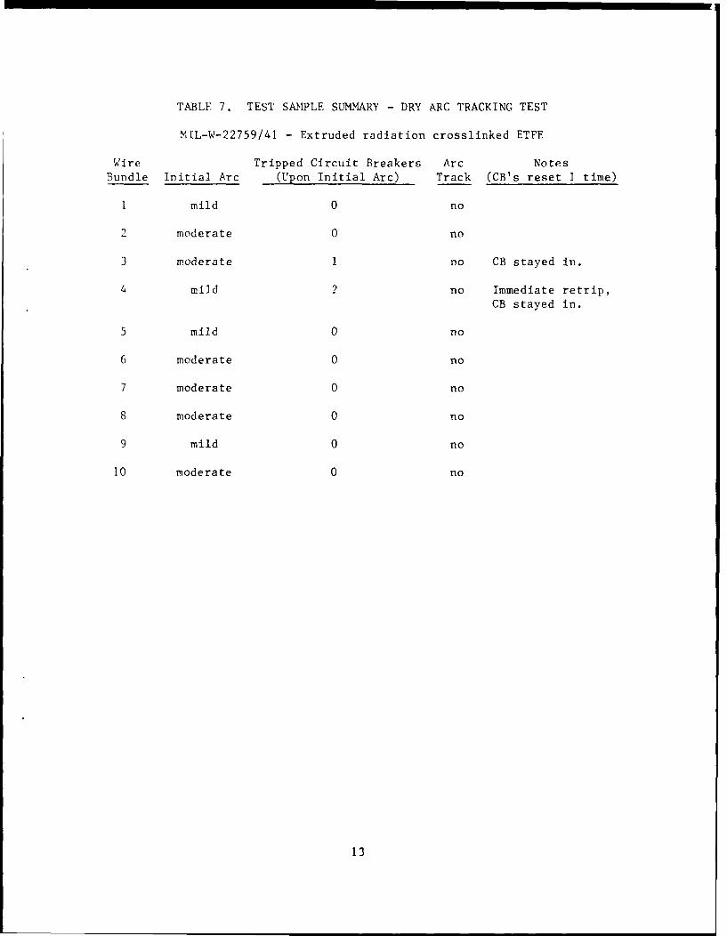
TABLE 7. TEST SAMPLE SUMMARY - DRY ABC TRACKING TEST
MIL-W-22759/41 - Extruded radiation crosslinked ETFE
Wire Tripped Circuit Breakers Arc NotesBundle Initial Arc (Upon Initial Arc) Track (CB's reset I time)
1 mild 0 no
2 moderate 0 no
3 moderate 1 no CB stayed in.
4 mild 2 no Immediate retrip,
CB stayed in.
5 mild 0 no
6 moderate 0 no
7 moderate 0 no
8 moderate 0 no
9 mild 0 no
10 moderate 0 no
13

TABLE 8. TEST SAMPLE SUMMARY - DRY ARC TRACKING TEST LABORATORY SAMPLE
Extruded radiation crosslinked ETFE
Wire Tripped Circuit Breakers Arc NotesBundle Initial Arc (Upon Initial Arc) Track (CB's reset 1 time)
1 moderate 0 no
2 mild 4 no All CB's
immediatelyretripped.
3 mild 4 no All CB's
immediatelyretripped.
4 mild 4 no CB stayed in.
CB retripped.
CB stayed in.CB stayed in.
5 mild 1 no CB stayed in.
14

00
A-4
04
15H

0
C)
zr
04
Is / ,
C-4C
16

40o
,A4
_mpaw.
1 172

APPENDIX A - SIXTY-DEGREE TEST
Chapter 1 - Federal Aviation Administration Part 25, App. G
(g) Sixty-degree test in compliance with Part 25.1359(d). A minimum of threespecimens of each wire specification (make and size) must be tested. Thespecimen of wire or cable (including insulation) must be placed at an angle of600 with the horizontal in the cabinet specified in paragraph (c) of thisappendix with the cabinet door open during the test or must be placed within achamber approximately 2 feet high x 1 foot x 1 foot, open at the top and at onevertical side (front), and which allows sufficient flow of air for completecombustion, but which is free from drafts. The specimen must be parallel to andapproximately 6 inches from the front of the chamber. The lower end of thespecimen must be held rigidly clamped. The upper end of the specimen must passover a pulley or rod and must have an appropriate weight attached to it so thatthe specimen is held tautly throughout the flammability test. The test specimenspan between lower clamp and upper pulley or rod must be 24 inches and must bemarked 8 inches from the lower end to indicate the central point for flameapplication. A flame from a Bunsen or Tirrill burner must be applied to 30seconds at the test mark. The burner must be mounted underneath the test mark onthe specimen, perpendicular to the specimen and at an angle of 300 to thevertical plane of the specimen. The burner must have a nominal bore of three-eighths inch and must be adjusted to provide a 3-inch-high flame with an innercone approximately one-third of the flame height. The minimum temperature of thehottest portion of the flame, as measured with a calibrated thermocouplepyrometer, may not be less than 1,7500 F. The burner must be positioned so thatthe hottest portion of the flame is applied to the test mark onthe wire. Flame time, burn length, and flaming time of drippings, if any, mustbe recorded. The burn length determined in accordance with paragraph (h) of thisappendix must be measured to the nearest one-tenth inch. Breaking of the wirespecimens is not considered a failure.
(h) Burn length. Burn length is the distance from the original edge to thefarthest evidence of damage to the test specimen due to flame impingement,including areas of partial or complete consumption, charring, or embrittlement,but not including areas sooted, stained, warped, or discolored, nor areas wherematerial has shrunk or melted away from the heat source.
A-I
*U S OOVERNMENT PRINTING OFFICE iOW"W911