i/a series hardware -...
TRANSCRIPT

PSS 21H-2Y6 B4
I/A Series® HARDWAREProduct Specifications
Intrinsically Safe I/O Subsystem
ISCM Base Unit for LB (Zone 2) Applications
ISCM Base, Extension and Redundancy Units for FB (Zone 1) Applications
The Intrinsically Safe I/O Subsystem provides integration between the Pepperl+Fuchs™ (P+F) modular intrinsically safe remote I/O systems and the I/A Series® system. The Intrinsically Safe Communications Module (ISCM) enables I/A Series control processors to view the P+F I/O modules as equivalent 200 Series Fieldbus Modules (FBMs), which can be monitored with standard I/A Series blocks and standard InFusion™ or I/A Series system/control configurator applications such as the InFusion Engineering Environment and the Integrated Control Configurator.
FEATURES
Intrinsically safe - supports Zone 2, Div. 2 or Zone 22 (LB-style) environments or Zone 1, or Zone 21 (FB-style) environments
ISCMs interface the 2 Mbps HDLC Module Fieldbus to the FCP270 or ZCP270
Up to 46 (for LB-style Zone 2 Applications) or48 (for FB-style Zone 1 Applications) P+F intrinsically safe I/O modules supported per
optionally redundant ISCM, with a total of16 ISCMs supported per I/A Series control processor (FCP270 or ZCP270); a maximum of 204 modules (ISCMs, I/O modules and 200 Series FBMs) supported per FCP270 and a maximum of 128 modules supported per ZCP270, provided the maximum CP Fieldbus load and intrinsically safe I/O power supply load is not exceeded.

PSS 21H-2Y6 B4Page 2
Redundant ISCMs allow either module to control the process. Role reversal is automatic on detected failures
Letterbug set through a letterbug module with rotary switch plugged into the ISCM.
Monitored by standard System Manager or I/A Series SMDH and FoxView™ displays
“CE” logo marked on product.
OVERVIEW
The Intrinsically Safe I/O Subsystem provides integration between the Pepperl+Fuchs (P+F) modular intrinsically safe remote I/O systems and the I/A Series system. The Intrinsically Safe Communications Module (ISCM) communicates between the two systems, as it enables I/A Series control processors to view supported P+F intrinsically safe I/O modules as equivalent 200 Series Fieldbus Modules (FBMs) over the I/A Series 2 Mbps HDLC Fieldbus. This allows the I/O modules to be monitored with standard I/A Series blocks and standard I/A Series or InFusion system/control configurator applications such as InFusion Engineering Environment and ICC.
This subsystem supports both the P+F intrinsically safe I/O modules and their associated base, extension or redundancy units for Zone 2, Div. 2 or Zone 22 (LB-style(1)) environments orZone 1 or Zone 21 (FB-style(2)) environments. Optionally redundant ISCMs are mounted directly on the appropriate P+F unit along with the I/O modules and power supplies, as shown in Figure 1 and Figure 2. Only I/O modules can be mounted in the extension units. Each I/O module can be plugged into any desired slot on the base or extension unit. ISCMs and power supplies are required to be plugged into their own dedicated slots.
Depending on the model type used, I/O modules can occupy one or two slots in their unit.
ISCMs are installed as single or redundant. In redundant configurations, both ISCMs are always active. In case of a module’s failure, the other provides backup coverage until the failed ISCM is returned to service. An ISCM for Zone 2 applications may support up to 46 LB-style I/O modules, while an ISCM for Zone 1 applications may support up to 48 FB-style I/O modules.
NOTEThe following 200 Series FBM features are not supported on the intrinsically safe I/O modules: Sequence of Events (SOE), TDR, time synchronization, ladder logic, and the EVENT, MDACT and DPIDA blocks.
NOTEThe limit of sixteen ISCMs per subsystem represents the theoretical maximum if the base, extension or redundancy units are not fully fitted with modules. Sixteen base units with sixteen extension units will connect a total of 16 x 46 I/O modules (736). The controller can handle up to 204. If dual-width modules are used, then the subsystem will have 16 x 23 dual-width I/O modules (368) which is outside the scope of the subsystem. In typical scenarios, eight units can be connected to one FCP270.
(1) Local Bus style.(2) Field Bus style.
PSS 21H-2Y6 B4Page 3
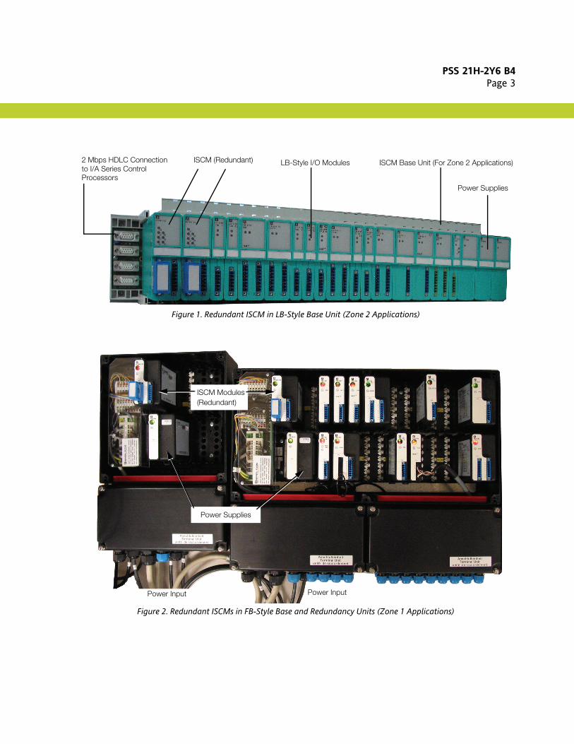
Figure 1. Redundant ISCM in LB-Style Base Unit (Zone 2 Applications)
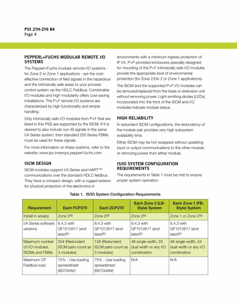
Figure 2. Redundant ISCMs in FB-Style Base and Redundancy Units (Zone 1 Applications)
2 Mbps HDLC Connectionto I/A Series Control
ISCM (Redundant) ISCM Base Unit (For Zone 2 Applications)
Processors
LB-Style I/O Modules
Power Supplies
Power Input
Power Supplies
ISCM Modules(Redundant)
Power Input
PSS 21H-2Y6 B4Page 4
PEPPERL+FUCHS MODULAR REMOTE I/O SYSTEMS
The Pepperl+Fuchs modular remote I/O systems - for Zone 2 or Zone 1 applications - are the cost-effective connection of field signals in the hazardous and the intrinsically safe areas to your process control system via the HDLC Fieldbus. Combinable I/O modules and high modularity offers cost-saving installations. The P+F remote I/O systems are characterized by high functionality and simple handling.
Only intrinsically safe I/O modules from P+F that are listed in this PSS are supported by the ISCM. If it is desired to also include non-IS signals in the same I/A Series system, then standard 200 Series FBMs must be used for these signals.
For more information on these systems, refer to the website: www.ips.invensys.pepperl-fuchs.com
ISCM DESIGN
ISCM modules support I/A Series and HART™ communications over the standard HDLC fieldbus. They have a compact design, with a rugged exterior for physical protection of the electronics in
environments with a minimum ingress protection of IP 54. P+F-provided enclosures specially designed for mounting of the P+F intrinsically safe I/O modules provide the appropriate level of environmental protection (for Zone 2/Div 2 or Zone 1 applications).
The ISCM and the supported P+F I/O modules can be removed/replaced from the base or extension unit without removing power. Light-emitting diodes (LEDs) incorporated into the front of the ISCM and I/O modules indicate module status.
HIGH RELIABILITY
In redundant ISCM configurations, the redundancy of the module pair provides very high subsystem availability time.
Either ISCM may be hot-swapped without upsetting input or output communications to the other module, or removing power from either module.
IS/IO SYSTEM CONFIGURATION REQUIREMENTS
The requirements in Table 1 must be met to ensure proper system operation:
Table 1. IS/IO System Configuration Requirements
Requirement Each FCP270 Each ZCP270Each Zone 2 (LB-
Style) SystemEach Zone 1 (FB-
Style) System
Install in area(s) Zone 2(a) Zone 2(a) Zone 2(a) Zone 1 or Zone 2(a)
I/A Series software versions
8.4.3 with QF1012617 (and later)(b)
8.4.3 with QF1012617 (and later)(b)
8.4.3 with QF1012617 (and later)(b)
8.4.3 with QF1012617 (and later)(b)
Maximum number of I/O modules, ISCMs and FBMs
204 (Redundant ISCM pairs count as 3 modules)
128 (Redundant ISCM pairs count as 3 modules)
46 single width, 23 dual width or any I/O combination
48 single width, 24 dual width or any I/O combination
Maximum CP Fieldbus load
75% - Use loading spreadsheet (B0700AV)
75% - Use loading spreadsheet (B0700AW)
N/A N/A

PSS 21H-2Y6 B4Page 5
ISCMs supported 16 single or redundant pairs
16 single or redundant pairs
One or two per LB-style system
One or two per FB-style system
Power supplies One or two Invensys supplied 24 Volt power supplies, power input 24 V dc or 85 - 265 V ac (or 125 V dc)
One or two Invensys supplied 24 Volt power supplies, power input 24 V dc or 85 - 265 V ac (or 125 V dc)
P+F supplied, two per base or extension unit. Three per unit are required for redundant systems. External optionally redundant 24 V dc power input
P+F supplied, one in main unit, one in redundancy unit, two in extension unit. External power input 24 V dc, 115 V ac or 230 V ac mains
24 V dc Boost Power
N/A N/A Required if 6x10-6x15 modules are installed
Required if 6x10-6x15 modules are installed
Analog Inputs and Analog Outputs
Configuration dependent
Configuration dependent
80 total, 40 each per base or extension unit
80 total, 40 each per base or extension unit
Digital I/O 2x02 modules
Configuration dependent
Configuration dependent
40 total, 20 each per base or extension unit
40 total, 20 each per base or extension unit
Other I/O Modules Configuration dependent
Configuration dependent
Any other combination if the above two limits are not reached.
Any other combination if the above two limits are not reached.
Maximum number of HART devices
Maximum Fieldbus load cannot be exceeded
Maximum Fieldbus load cannot be exceeded
80 80
Maximum number of HART I/O point connections
480 points will use 29% of the fieldbus load capacity
480 points will use 35% of the fieldbus load capacity
480 480
Maximum number of HART pass through sessions
12 12 4 4
(a) Be aware that Zone 1 and Zone 2 installations have other special requirements for power consumption and dissipation. These are observed automatically by P+F’s ATEX audited factories. Other panel builders would have to obtain their own certificates equivalent to P+F’s PTB07ATEX1075 for Zone 1 and PF08CERT1234 for Zone 2.
(b) Windows XP and Windows Server 2003 workstation operating systems only.
Table 1. IS/IO System Configuration Requirements (Continued)
Requirement Each FCP270 Each ZCP270Each Zone 2 (LB-
Style) SystemEach Zone 1 (FB-
Style) System

PSS 21H-2Y6 B4Page 6
MODULAR UNIT MOUNTING
The ISCM mounts on supported P+F-supplied LB-style or FB-style base or extension units, which accommodate different quantities of P+F I/O modules, depending on the application.The ISCM base unit includes signal connectors for the ISCM and P+F I/O modules, redundant independent power connections, and 2 Mbps HDLC module Fieldbus connections for communications to the I/A Series FCP270 or ZCP270.
Redundant ISCMs must be located in the left-most two slots in the LB-style base units. One each of the FB-style ISCMs are located in the main and redundancy units.
Table 2 lists the available ISCM modules and available support equipment.
Zone 2 (LB-Style) P+F Intrinsically Safe Units
and Support Equipment To Support the ISCM
Table 3 lists the supported Zone 2 (LB-Style) I/O base, redundancy and extension units and their associated enclosures and power supplies.
Table 2. ISCM Modules and Support Equipment
Invensys Part No. P+F Model No. Description
P0924GT ISCM8100 Intrinsically Safe Communication Module for Zone 2(LB-style) applications
P0924GU ISCM8200 Intrinsically Safe Communication Module for Zone 1(FB-style) applications
P0924GV LTBM8001 Letterbug rotary switch module (plugs into ISCM8100/8200)
Table 3. P+F Intrinsically Safe Units and Support Equipment To Support the ISCM (Zone 2, LB-Style)
P+F Model No.(a)
(a) Visit the IPS Portal (www.ips.invensys.pepperl-fuchs.com) to order this equipment as it does not have an Invensys part number.
Description
LB 9022 F Zone 2 Redundancy Base Unit with 22 slots for Zone 2 (LB-style) applications
LB 9024 Zone 2 Extension Unit with 24 slots
LB 9547-S70-F Zone 2 stainless steel enclosure with 46 slots for Zone 2 (LB-style) applications
LB 9006 C Zone 2 power supply - 24 V dc input
NOTE: Two LB 9006 C power supplies are required for each base and extension unit. Where redundant ISCMs are also installed, a third power supply is required in each unit to support redundancy.

PSS 21H-2Y6 B4Page 7
Zone 1 (FB-Style) P+F Intrinsically Safe Units and Support Equipment To Support the ISCM
Table 4 lists the supported Zone 1 (FB-Style) I/O base, redundancy and extension units and their associated enclosures and power supplies.
Table 4. P+F Intrinsically Safe Units and Support Equipment To Support the ISCM (Zone 1, FB-Style)
P+F Model No.(a)
(a) Visit the IPS Portal (www.ips.invensys.pepperl-fuchs.com) to order this equipment as it does not have an Invensys part number.
Description
FB 9224-PG0 Zone 1 GRP enclosure with 24 slots
FB 9225-PG0 Zone 1 GRP enclosure with 24 slots (redundant)
FB 9248-PG0 Zone 1 GRP enclosure with 48 slots
FB 9249-PG0 Zone 1 GRP enclosure with 48 slots (redundant)
FB 9224-S60 Zone 1 stainless steel enclosure with 24 slots
FB 9225-S70 Zone 1 stainless steel enclosure with 24 slots (redundant)
FB 9248-S70 Zone 1 stainless steel enclosure with 48 slots
FB 9249-S80 Zone 1 stainless steel enclosure with 48 slots (redundant)
FB 9205 D Zone 1 power supply - 230 V ac / boost power for DO modules FB621x
FB 9206 D Zone 1 power supply - 24 V dc input
FB 9215 B Zone 1 power supply - 230 V ac input
FB 9216 B Zone 1 power supply - 115 V ac input

PSS 21H-2Y6 B4Page 8
Table 5 details the units and equipment provided with each Zone 1 (FB-Style) GRP enclosure.Figure 3 displays examples of these enclosures loaded.
Table 5. Zone 1 (FB-Style) GRP Enclosures Equipment)
P+F Model No.(a) Description Contents
FB 9224-PG0 Zone 1 GRP enclosure with 24 slots
1 socket for communication interface FB 820X
1 socket for power supply FB 92XX
24 sockets for I/O modules
Cable glands (plastic)
2 x M20 for power supply
2 x M20 for bus cable
1 x M20 for service bus cable
1 x M20 for later expansion for redundancy
24 x M16 for 24 I/O cables
24 x M16 blanking plugs
Terminals for mains connection and bus VBG4 protected.
FB 9225-PG0 Zone 1 GRP enclosure with 24 slots (redundant)
2 sockets for communication interface FB 820X
2 sockets for power supply FB 92XX
24 sockets for I/O modules
Cable glands (plastic)
2 x M20 for power supply
2 x M20 for bus cable
1 x M20 for service bus cable
1 x M20 for expansion for redundancy
24 x M16 for 24 I/O cables
24 x M16 blanking plugs
Terminals for mains connection and bus VBG4 protected.

PSS 21H-2Y6 B4Page 9
FB 9248-PG0 Zone 1 GRP enclosure with 48 slots
1 socket for communication interface FB 820X
2 sockets for power supply FB 92XX
48 sockets for I/O modules
Cable glands (plastic) per basic and expansion unit
2 x M20 for power supply
2 x M20 for bus cable
1 x M20 for service bus cable
1 x M20 for later expansion for redundancy
24 x M16 for 24 I/O cables
24 x M16 blanking plugs
Terminals for mains connection and bus VBG4 protected.
FB 9249-PG0 Zone 1 GRP enclosure with 48 slots (redundant)
2 sockets for communication interface FB 820X
4 sockets for power supply FB 92XX
48 sockets for I/O modules
Cable glands (plastic) per basic and expansion unit
2 x M20 for power supply
2 x M20 for bus cable
1 x M20 for service bus cable
1 x M20 for expansion for redundancy
24 x M16 for 24 I/O cables
24 x M16 blanking plugs
Terminals for mains connection and bus VBG4 protected.
(a) Visit the IPS Portal (www.ips.invensys.pepperl-fuchs.com) to order this equipment as it does not have an Invensys part number.
Table 5. Zone 1 (FB-Style) GRP Enclosures Equipment) (Continued)
P+F Model No.(a) Description Contents

PSS 21H-2Y6 B4Page 10
Figure 3. Loaded Zone 1 (FB-Style) GRP Enclosures with Example Units
Zone 1 GRP Enclosure with 24 Slots Zone 1 GRP Enclosure with 24 Slots (Redundant)
Zone 1 GRP Enclosure with 48 Slots (FB 9248-PG0)
Zone 1 GRP Enclosure with 48 Slots (Redundant) (FB 9249-PG0)
(FB 9225-PG0)(FB 9224-PG0)
Dimensional Drawings
136.2 mm (5.4 in)
405
mm
(15.
9 in
)
271
mm
(10.
7 in
)
271 mm (10.7 in) 212 mm (8.3 in) 544 mm (21.4 in)

PSS 21H-2Y6 B4Page 11
Figure 4 displays examples of the Zone 1 (FB-Style) stainless steel enclosures loaded with the appropriate units and equipment.
Figure 4. Loaded Zone 1 (FB-Style) Stainless Steel Enclosures with Example Units
NOTE: Visit the IPS Portal (www.ips.invensys.pepperl-fuchs.com) for more details on these field enclosures, includingthe field enclosures available and how to order them.
Stainless steel enclosure supports one
Legend:
(1) FOL Coupler (Optical fibre)
(2) Busstation
(3) Option screen rails
(4) Redundancy unit
(5) Optional marshalling terminals
redundant IS unit (FB 9249-S80)
Available field enclosure dimensions800 x 1000 x 300 mm
800 x 600 x 300 mm
with 48 slots for I/O modules or 24
Available field enclosure dimensions600 x 600 x 400 mm
Available field enclosure dimensions1000 x 800 x 400 mm
Zone 1 stainless steel FB Remote I/Oenclosure with optional prewired marshalling to terminals supports
I/O modules.Also includes screen rail.
Zone 1 stainless steel FB Remote I/Oenclosure with optional valve banks,and optional marshalling terminals
I/O modules or 24 slots for dual-widthI/O modules.
one IS unit with 24 slots (FB 9224-S60)for I/O modules or 12 slots for dual-width
supports one redundant IS unit(FB 9249-S80) with 48 slots for
Also includes screen rail.
slots for dual-width I/O modules.

PSS 21H-2Y6 B4Page 12
MODULE FIELDBUS COMMUNICATION
The ISCM supports the redundant 2 Mbps HDLC module Fieldbus to communicate with the FCP270 or ZCP270 (via optionally redundant FCM100E/Et modules), as shown in Figure 5 and Figure 6.
The FCP270 can connect to both P+F I/O modules and 200 Series FBMs, provided the appropriate sizing constraints are followed (detailed in the Field Control Processor 270 (FCP270) Sizing Guidelines and Excel Workbook (B0700AV) and Z-Module Control Processor 270 (ZCP270) Sizing Guidelines and Excel Workbook (B0700AW)). To connect simultaneously to 200 Series FBMs, the FCP270 must use the FEM100 to add up to three Expanded Fieldbuses for these FBMs.
NOTEThe FCP270, 200 Series FBMs and their support hardware are suitable for Zone 2 or Class I, Div.2 areas only. Installing this equipment in a Zone 1 area requires the employment of additional protection methods and is your responsibility to implement.
NOTEWhen an FCP270 is connected to both P+F I/O modules and 200 Series FBMs via an FEM100, the Expanded Fieldbus 1 cannot be connected to any FBM baseplates (must be left disconnected), and Expanded Fieldbus 2 can only be used with FBM baseplates addresses 1, 2 and 3 to avoid letterbug addressing conflicts. Expanded Fieldbus 2 and 3 can connect and address all four baseplates (0 through 3).
For more information on the FEM100 and the Expanded Fieldbus, refer to FEM100 Fieldbus Expansion Module (PSS 21H-2Y16 B4).
To connect to a ZCP270, the ISCM connects to an FCM100E/Et module, which in turn connects to the ZCP270 over a 100 Mbps Ethernet fiber optic network (via The MESH control network).
For Zone 2 (LB-style) applications, a maximum of 60 meters (197 ft) of standard fieldbus cable may be used between the FCP270 or FCM100E/Et and the remote I/O system. For Zone 1 (FB-Style) applications, a maximum of 152 meters (500 ft) of high quality twinaxial cable may be used between the FCP270 or FCM100E/Et and the remote I/O system.

PSS 21H-2Y6 B4Page 13
Figure 5. Typical LB-Style (Zone 2) ISCM to FCP270/ZCP270 Network Configuration (Simplified)
FCP270
FCP270
FCM
100E
FCM
100E
100 Mbps Ethernet Fiber 2 Mbps HDLC Module FieldbusOptic Fieldbus (Redundant)(Shielded Twisted Pair Cables)
ZCP270 Control Processor
Modular Baseplate
OR
ISCM
ISCM
P+F LB-Style I/O Modules Power Supplies
FCM100Es
FCP270 Only
FCP270 ControlProcessors
Toward ZCP270Toward FCP270
60m (197 ft) max.
Baseplate
(Fault-Tolerant)(Redundant)
To Other FCM100Es
(Fault-Tolerant)
(See Note 2)
To Other FEMs/FBMs/ISCMs(See Note 2)
24 V dcPowerConnections
P+F LB-Style Base Unit
StandardP+F HDLC
TheMESHControlNetwork
To Next P+F
FieldbusCables
HDLCTerminator(P0916RB)OR
P+F LB-Style I/O Modules Power Supplies
P+F LB-Style Expansion Unit (One Expansion Unit Per Base Unit.)LB Base Unit
X40 - 24 V dcBooster
3. X40 - 24 V dc Booster provides extra auxiliary power for the 4-channel digital outputs for the LB 6110 to LB6115 I/O modules.
(See Note 3)
X03X02X01
(See Note 4)
4. X03 provides power for the shutdown input. Alternatively, shutdown input can be done by use of a contact closure (contact input)
X02 and X01 are for the 24 V dc input power connections.
X40 - 24 V dcBooster(See Note 3)
X03X02X01(See Note 4)
Notes:1. For sizing constraints, refer to Chapter 1 of the B0700DP manual.2. If FEM100 is used with an FCP270 connected to a P+F base/extension unit, there are limitations on the Expansion Fieldbus. See
Appendix A in the Intrinsically Safe I/O Subsystem User’s Guide (B0700DP). FEM100s cannot be directly connected to a P+Fbase/extension unit.
to this connector.
P+F StyleExtensionCable
22 Slots for Single-Width Modules/11 Slots for Dual-Width Modules
24 Slots for Single-Width Modules/12 Slots for Dual-Width Modules

PSS 21H-2Y6 B4Page 14
Figure 6. Typical FB-Style ISCM to FCP270/ZCP270 Network Configuration (Simplified)
Notes:1. For sizing constraints, refer to Chapter 1 of the B0700DP manual.2. If FEM100 is used with an FCP270 connected to a P+F base/extension unit, there are limitations on the Expansion Fieldbus. See
Appendix A of the B0700DP manual for details. FEM100s cannot be directly connected to a P+F base/extension unit.
FCP270
FCP270
FCM
100E
FCM
100E
100 Mbps Ethernet Fiber Cable (P0903VY) Optic Fieldbus (Redundant)
ZCP270 Control Processor
Modular Baseplate
OR
FCM100Es
FCP270 Only
FCP270 ControlProcessors
To ZCP270To FCP270
Baseplate
(Fault-Tolerant)(Redundant)
To Other FCM100Es
(Fault-Tolerant)
(See Note 2)
To Other FEMs/FBMs/ISCMs(See Note 2)
FB-Style ISCMRedundancy Unit (See Note 3)
FB-Style ISCMMain Unit (See Note 3)
FB-Style ISCMExtension Unit (See Note 3)
TCA
TCA
HDLC Cables (P0170GF/GG)(Shielded Twisted Pair Cables)
Cable (FB 9271) Cable (FB 9272) Cable (FB 9273)
110 Ohm Terminations at Each End of the HDLC Cables (152 m (500 ft) Max.) - TCA is on the P0903VY cable
Splitter (P0926LC)
Splitter (P0926LC)
3. FB 9249-PG0 enclosure configuration is shown in this figure. Additional enclosure configurations are available. ISCMs are
TheMESHControlNetwork
plugged into the Main or Redundancy Unit.

PSS 21H-2Y6 B4Page 15
P+F INTRINSICALLY SAFE I/O MODULES SUPPORTED
Supported P+F Intrinsically Safe I/O Modules and Front Connectors Specifications for Zone 2 or
Class I, Div. 2 Environments
The Intrinsically Safe I/O Subsystem supports the following Pepperl+Fuchs intrinsically safe I/O modules in Zone 2 or Class I, Div. 2 environments with a minimum ingress protection of IP 54.
Table 6. Supported P+F Intrinsically Safe I/O Modules (Zone 2 - LB-Style)
P+F Model No.
I/O Channels
Description
Similar to I/A Series
FBMUnit Slot
Analog Input
Analog Output
Digital Input
Digital Output
LB 1101 A - - 2 - Digital Input 207 1
LB 1103 F - - 2(a) - Frequency + direction of rotation (15 KHz)
206 1
LB 1104 F - - 2(a) - Pulse count + direction of rotation (15 KHz)
206 1
LB 1103 FL - - 2(a) - Frequency low + direction of rotation (300 Hz)
206 1
LB 1104 FL - - 2(a) - Pulse count low + direction of rotation (300 Hz)
206 1
LB 1108 A - - 8 - Digital Input 207 2
LB 2101 A - - 2 1 Digital Output with position feedback (22 V, 315 Ω)
241 1
LB 2101 E - - 2 1 Digital Output with position feedback + shutdown input (22 V, 315 Ω)
241 1
LB 2102 A - - 2 1 Digital Output with position feedback (24 V, 210 Ω)
241 1
LB 2103 A - - 2 1 Digital Output with position feedback (24 V, 360 Ω)
241 1
LB 2103 E - - 2 1 Digital Output with position feedback + shutdown input (24 V, 360 Ω)
241 1
LB 2104 A - - 2 1 Digital Output with position feedback (22 V, 220 Ω)
241 1
LB 2105 A - - 2 1 Digital Output with position feedback (22.8 V, 290 Ω)
241 1

PSS 21H-2Y6 B4Page 16
LB 2105 E - - 2 1 Digital Output with position feedback + shutdown input (22.8 V, 290 Ω)
241 1
LB 2112 A - - 2 1 Digital Output with position feedback (25.3 V, 329 Ω)
241 1
LB 2112 E - - 2 1 Digital Output with position feedback + shutdown input (25.3 V, 329 Ω)
241 1
LB 2113 A - - 2 1 Digital Output with position feedback (26.7 V, 509 Ω)
241 1
LB 2113 E - - 2 1 Digital Output with position feedback + shutdown input (26.7 V, 509 Ω)
241 1
LB 3102 A 1 - - - HART® input with Transmitter power (16.5V)
214 1
LB 3104 A 4 - - - Transmitter power 201 2
LB 3105 A 4 - - - HART® and Transmitter power 214 2
LB 4102 A - 1 - - HART® output 215 1
LB 4102 C - 1 - - HART® output with shutdown input 215 1
LB 4104 A - 4 - - Analog Output 237 2
LB 4105 C - 4 - - HART® output with shutdown input 215 2
LB 4105 D - 4 - - HART® output with LFD 215 2
LB 5101 F3 1 - - - 3-wire RTD input 203 1
LB 5101 F4 1 - - - 4-wire RTD input 203 1
LB 5102 F 1 - - - T/C with internal/external CJC RTD input
202 1
LB 5106 A 1 - - - 0 - 10 V input 201 1
LB 5104 F3 4 - - - 3 wire RTD input 203 2
LB 5104 F4 4 - - - 4 wire RTD input 203 2
LB 5105 F 4 - - - T/C with internal CJC RTD 202 2
LB 6101 H - - - 2 Digital Relay Output (230 V/24 V) 242 1
Table 6. Supported P+F Intrinsically Safe I/O Modules (Zone 2 - LB-Style) (Continued)
P+F Model No.
I/O Channels
Description
Similar to I/A Series
FBMUnit Slot
Analog Input
Analog Output
Digital Input
Digital Output

PSS 21H-2Y6 B4Page 17
LB 6005 A - - - 4 Digital Relay Output (230 V/24 V) 242 2
LB 6006 A - - - 8 Digital Relay Output (24 V) 242 2
LB 6108 A - - - 8 20V/8 mA Digital Output per channel, with shut down input
242 2
LB 6110 A - - - 4 Solenoid driver uses boost power (24.5 V, 370 Ω)
242 2
LB 6110 E - - - 4 Solenoid driver uses boost power + shutdown input (24.5 V, 370 Ω)
242 2
LB 6111 A - - - 4 Solenoid driver uses boost power (24.5 V, 320 Ω)
242 2
LB 6111 E - - - 4 Solenoid driver uses boost power + shutdown input (24.5 V, 320 Ω)
242 2
LB 6112 A - - - 4 Solenoid driver uses boost power (17 V, 185 Ω)
242 2
LB 6112 E - - - 4 Solenoid driver uses boost power + shutdown input (17 V, 185 Ω)
242 2
LB 6113 A - - - 4 Solenoid driver uses boost power (23 V, 290 Ω)
242 2
LB 6113 E - - - 4 Solenoid driver uses boost power + shutdown input (23 V, 290 Ω)
242 2
LB 6114 A - - - 4 Solenoid driver uses boost power (23 V, 355 Ω)
242 2
LB 6114 E - - - 4 Solenoid driver uses boost power + shutdown input (23 V, 355 Ω)
242 2
LB 6115 A - - - 4 Solenoid driver uses boost power (16.2 V, 78 Ω)
242 2
LB 6115 ES - - - 4 Solenoid driver uses boost power + shutdown input (16.2 V, 78 Ω)
242 2
(a) Although these modules have two channels, the second channel is for direction detection only.
Table 6. Supported P+F Intrinsically Safe I/O Modules (Zone 2 - LB-Style) (Continued)
P+F Model No.
I/O Channels
Description
Similar to I/A Series
FBMUnit Slot
Analog Input
Analog Output
Digital Input
Digital Output

PSS 21H-2Y6 B4Page 18
Table 7 lists the front connectors used with the Pepperl+Fuchs intrinsically safe I/O modules listed in Table 6. These front connector types are shown in Figure 7.
Figure 7. Front Connector Types for Supported P+F Intrinsically Safe I/O Modules (Zones 1 and 2)
Wire ClampConnector
ScrewConnector
Front ScrewConnector
Hood CoverOnly for ScrewConnector (2)
Coding Strip OnlyWhen Desired
(Not Coded Ex Works)
Ex-e Connector For Newer Hood Cover Supplied with Ex-e Connector For NewerEx-e Type FB-Style I/O Modules with IP30 CoverEx-e Type FB-Style I/O Modules
Table 7. Front Connectors for Supported P+F Intrinsically Safe I/O Modules (Zone 2)
P+F Model No. Description Signal Type
6 Pole Front Connectors
LB 9007 A Screw terminals connector, green, 6-pole Non-Intrinsically Safe
LB 9008 A Cover for connector green, 6-pole Non-Intrinsically Safe
LB 9009 A Wire clamp connector green, 6-pole Non-Intrinsically Safe
LB 9107 A Screw terminals connector blue, 6-pole Intrinsically Safe
LB 9107 P Wire clamp connector blue, 6-pole Intrinsically Safe
LB 9108 A Cover for connector blue, 6-pole Intrinsically Safe
LB 9111 A Cold junction module with hood, blue, 6-pole Intrinsically Safe

PSS 21H-2Y6 B4Page 19
LB 9117 A Front screw connector, blue, 6-pole Intrinsically Safe
8 Pole Front Connectors
LB 9013 A Screw terminals connector green, 8-pole Non-Intrinsically Safe
LB 9014 A Screw terminals connector green, 2 x 8-pole, with label 1-8 and 9-16 Non-Intrinsically Safe
LB 9015 A Wire clamp connector green, 8-pole Non-Intrinsically Safe
LB 9016 A Wire clamp connector green, 2 x 8-pole, with label 1-8 and 9-16 Non-Intrinsically Safe
LB 9018 A Front screw connector 1-8, green Non-Intrinsically Safe
LB 9019 A Front screw connector 1-8 and 9-16, green Non-Intrinsically Safe
LB 9113 A Screw terminals connector blue, 8-pole Intrinsically Safe
LB 9124 A Screw terminals connector blue, 2 x 8-pole, with label 1-8 and 9-16 Intrinsically Safe
LB 9115 A Wire clamp connector blue, 8-pole Intrinsically Safe
LB 9116 A Wire clamp connector blue, 2 x 8-pole, with label 1-8 and 9-16 Intrinsically Safe
LB 9118 A Front screw connector 1-8, blue Intrinsically Safe
LB 9119 A Front screw connector, 2 x 8-pole. 1-8 and 9-16, blue Intrinsically Safe
LB 9120 A Cover for connector blue, 8-pole Intrinsically Safe
LB 9020 A Coding strip for coding the male connector (100 pcs.) n/a
Table 7. Front Connectors for Supported P+F Intrinsically Safe I/O Modules (Zone 2) (Continued)
P+F Model No. Description Signal Type

PSS 21H-2Y6 B4Page 20
P
F
F
F
F
F
F
FF
FF
FF
FF
Supported P+F Intrinsically Safe I/O Modules and Front Connectors Specifications for Zone 1
Environments
The Intrinsically Safe I/O Subsystem supports the following Pepperl+Fuchs intrinsically safe I/O modules in Zone 1 environments with a minimum ingress protection of IP 54.
NOTECertain FB-Style (Zone 1) I/O modules supporting Ex-e terminals use cable tails to attach the EX-e connectors. Newer I/O modules are available with plug-in front EX-e connectors instead of cable tails - as shown in Figure 7. This simplifies installation and the new EX-e terminals no longer require marshalling. The new cage clamp type plug-in connectors are covered by a hood to ensure IP30 protection, as shown in Figure 7. Plastic lugs on the hood ensure that every opening is covered unless occupied by a field wire. Lugs are broken off as more wires are used. Once screwed down, the hood cover secures the connector to the module.
Table 8. Supported P+F Intrinsically Safe I/O Modules (Zone 1 - FB-Style)
+F Model No.
I/O Channels
Description
Similar to I/A Series
FBMUnitSlot
Analog Input
Analog Output
Digital Input
Digital Output
B 1201 B - - 2 - Digital Input 207 1
B 1203 F - - 2(a) - Frequency + direction of rotation (15 KHz)
206 1
B 1204 F - - 2(a) - Pulse count + direction of rotation (15 KHz)
206 1
B 1203 FL - - 2(a) - Frequency low + direction of rotation (300 Hz)
206 1
B 1204 FL - - 2(a) - Pulse count low + direction of rotation (300 Hz)
206 1
B 1208 B - - 8 - Digital Input 207 2
B 1301 BB 1301 B200(b)
- - 2 - Increased safety (NON IS) Digital Input 207 1
B 1303 FB 1303 F2(b)
- - 2(a) - Frequency + direction of rotation (15 KHz)
206 1
B 1303 FLB 1303 FL2(b)
- - 2(a) - Frequency low + direction of rotation (300 Hz)
206 1
B 1304 FB 1304 F2(b)
- - 2(a) - Pulse count + direction of rotation (15 KHz)
206 1
PSS 21H-2Y6 B4Page 21
FF
FF
F
F
F
F
F
F
F
F
F
F
F
F
F
P
B 1304 FLB 1304 FL2(b)
- - 2(a) - Pulse count low + direction of rotation (300 Hz)
206 1
B 1308 BB 1308 B200(b)
- - 8 - Digital Input 207 2
B 2201 B - - 2 1 Digital Output with position feedback (22 V, 315 Ω)
241 1
B 2201 E - - 2 1 Digital Output with position feedback + shutdown input (22 V, 315 Ω)
241 1
B 2202 B - - 2 1 Digital Output with position feedback (24 V, 210 Ω)
241 1
B 2203 B - - 2 1 Digital Output with position feedback (24 V, 360 Ω)
241 1
B 2203 E - - 2 1 Digital Output with position feedback + shutdown input (24 V, 360 Ω)
241 1
B 2204 B - - 2 1 Digital Output with position feedback (22 V, 220 Ω)
241 1
B 2205 B - - 2 1 Digital Output with position feedback (22.8 V, 290 Ω)
241 1
B 2205 E - - 2 1 Digital Output with position feedback + shutdown input (22.8 V, 290 Ω)
241 1
B 2212 B - - 2 1 Digital Output with position feedback (25.3 V, 329 Ω)
241 1
B 2212 E - - 2 1 Digital Output with position feedback + shutdown input (25.3 V, 329 Ω)
241 1
B 2213 B - - 2 1 Digital Output with position feedback (26.7 V, 509 Ω)
241 1
B 2213 E - - 2 1 Digital Output with position feedback + shutdown input (26.7 V, 509 Ω)
241 1
B 3202 B 1 - - - HART® input with Transmitter power (16.5V)
214 1
Table 8. Supported P+F Intrinsically Safe I/O Modules (Zone 1 - FB-Style) (Continued)
+F Model No.
I/O Channels
Description
Similar to I/A Series
FBMUnitSlot
Analog Input
Analog Output
Digital Input
Digital Output

PSS 21H-2Y6 B4Page 22
F
F
FF
FF
F
F
FF
F
F
F
FF
F
F
F
F
F
F
F
F
F
P
B 3204 B 4 - - - Transmitter power 201 2
B 3205 B 4 - - - HART® and Transmitter power 214 2
B 3302 BB 3302 B200(b)
1 - - - HART® input with Transmitter power (16.5V)
214 1
B 3305 BB 3305 B200(b)
4 - - - HART® and Transmitter power 214 2
B 4202 B - 1 - - HART® output 215 1
B 4202 C - 1 - - HART® output with shutdown input 215 1
B 4302 CB 4302 C200(b)
- 1 - - HART® output with shutdown input 215 1
B 4204 B - 4 - - Analog Output 237 2
B 4205 C - 4 - - HART® output with shutdown input 215 2
B 4205 D - 4 - - HART® output with LFD 215 2
B 4305 BB 4305 B200(b)
- 4 - - HART® output with Ex-e 215 2
B 5201 F3 1 - - - 3 wire RTD input 203 1
B 5201 F4 1 - - - 4 wire RTD input 203 1
B 5202 F 1 - - - T/C with internal/external CJC RTD input
202 1
B 5204 F3 4 - - - 3 wire RTD input 203 2
B 5204 F4 4 - - - 4 wire RTD input 203 2
B 5205 F 4 - - - T/C with internal CJC RTD 202 2
B 5206 B 1 - - - 0 - 10 V input 201 1
B 6208 B - - - 8 20V/8mA Digital Output per channel, with shutdown input
242 2
B 6210 B - - - 4 Solenoid driver uses boost power (24.5 V, 370 Ω)
242 2
Table 8. Supported P+F Intrinsically Safe I/O Modules (Zone 1 - FB-Style) (Continued)
+F Model No.
I/O Channels
Description
Similar to I/A Series
FBMUnitSlot
Analog Input
Analog Output
Digital Input
Digital Output
PSS 21H-2Y6 B4Page 23
F
F
F
F
F
F
F
F
F
F
F
F
F
FF
FF
F
(a(b
P
B 6210 E - - - 4 Solenoid driver uses boost power+ shutdown input (24.5 V, 370 Ω)
242 2
B 6211 B - - - 4 Solenoid driver use boost power (24.5 V, 320 Ω)
242 2
B 6211 E - - - 4 Solenoid driver uses boost power+ shutdown input (24.5 V, 320 Ω)
242 2
B 6212 B - - - 4 Solenoid driver uses boost power (17.5 V, 185 Ω)
242 2
B 6212 E - - - 4 Solenoid driver uses boost power+ shutdown input (17.5 V, 185 Ω)
242 2
B 6213 B - - - 4 Solenoid driver uses boost power (23 V, 290 Ω)
242 2
B 6213 E - - - 4 Solenoid driver uses boost power+ shutdown input (23 V, 290 Ω)
242 2
B 6214 B - - - 4 Solenoid driver uses boost power (23 V, 355 Ω)
242 2
B 6214 E - - - 4 Solenoid driver uses boost power+ shutdown input (23 V, 355 Ω)
242 2
B 6215 B - - - 4 Solenoid driver uses boost power (16.2 V, 78 Ω)
242 2
B 6215 ES - - - 4 Solenoid driver uses boost power+ shutdown input (16.2 V, 78 Ω)
242 2
B 6301 H200 - - - 2 Digital Relay Output (230 V/24 V) 242 1
B 6305 B200 - - - 4 Digital Relay Output (230 V/24 V) 242 2
B 6306 BB 6306 B200(b)
- - - 8 Digital Relay Output (24 V) 242 2
B 6308 BB 6308 B200(b)
- - - 8 20V/8mA Digital Output per channel, with shutdown input
242 2
B 9293 F - - - - HDLC Bus Termination Module - 1
) Although these modules have two channels, the second channel is for direction detection only.) This FB-style I/O module has front-mounted Ex-e connector with cable tails. A newer I/O module, listed above this I/O module in the same
table cell, is available for this I/O module with a plug-in front EX-e connector instead of cable tails.
Table 8. Supported P+F Intrinsically Safe I/O Modules (Zone 1 - FB-Style) (Continued)
+F Model No.
I/O Channels
Description
Similar to I/A Series
FBMUnitSlot
Analog Input
Analog Output
Digital Input
Digital Output
PSS 21H-2Y6 B4Page 24
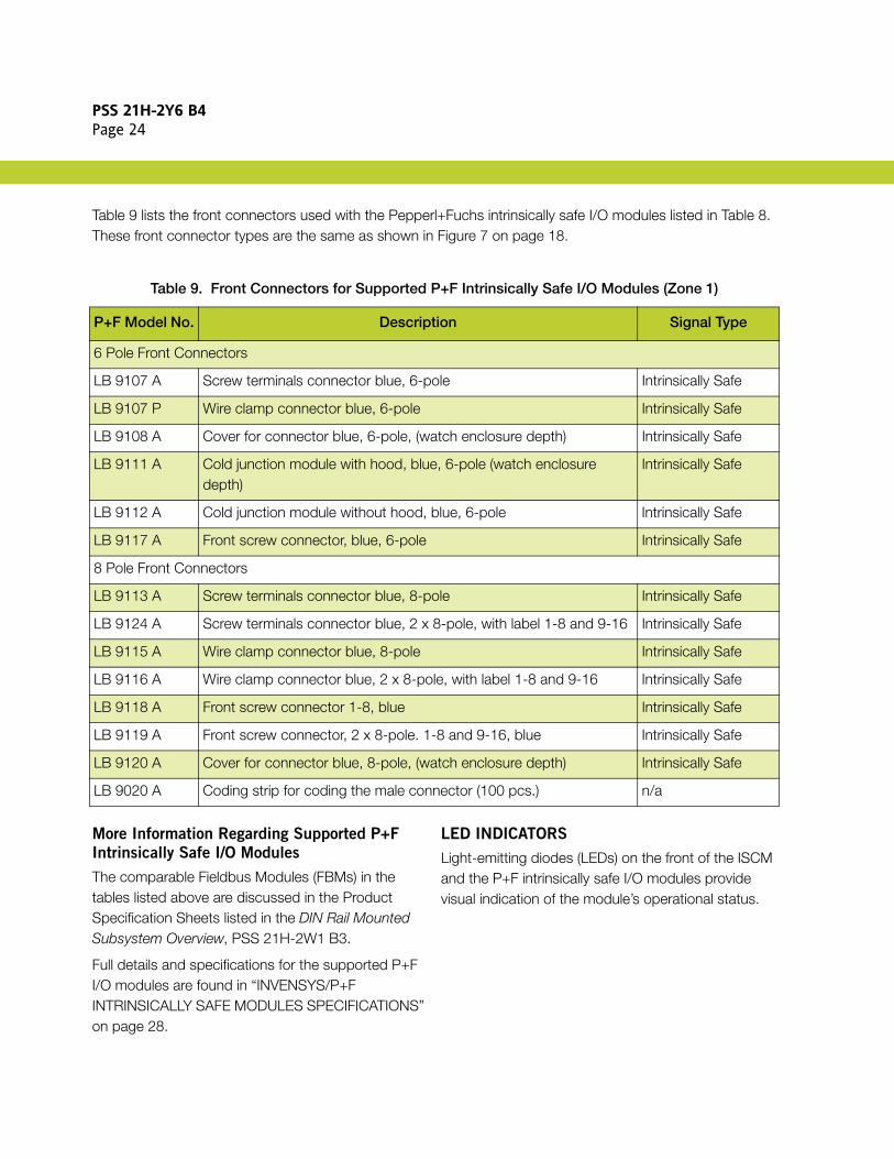
Table 9 lists the front connectors used with the Pepperl+Fuchs intrinsically safe I/O modules listed in Table 8. These front connector types are the same as shown in Figure 7 on page 18.
More Information Regarding Supported P+F
Intrinsically Safe I/O Modules
The comparable Fieldbus Modules (FBMs) in the tables listed above are discussed in the Product Specification Sheets listed in the DIN Rail Mounted Subsystem Overview, PSS 21H-2W1 B3.
Full details and specifications for the supported P+F I/O modules are found in “INVENSYS/P+F INTRINSICALLY SAFE MODULES SPECIFICATIONS” on page 28.
LED INDICATORS
Light-emitting diodes (LEDs) on the front of the ISCM and the P+F intrinsically safe I/O modules provide visual indication of the module’s operational status.
Table 9. Front Connectors for Supported P+F Intrinsically Safe I/O Modules (Zone 1)
P+F Model No. Description Signal Type
6 Pole Front Connectors
LB 9107 A Screw terminals connector blue, 6-pole Intrinsically Safe
LB 9107 P Wire clamp connector blue, 6-pole Intrinsically Safe
LB 9108 A Cover for connector blue, 6-pole, (watch enclosure depth) Intrinsically Safe
LB 9111 A Cold junction module with hood, blue, 6-pole (watch enclosure depth)
Intrinsically Safe
LB 9112 A Cold junction module without hood, blue, 6-pole Intrinsically Safe
LB 9117 A Front screw connector, blue, 6-pole Intrinsically Safe
8 Pole Front Connectors
LB 9113 A Screw terminals connector blue, 8-pole Intrinsically Safe
LB 9124 A Screw terminals connector blue, 2 x 8-pole, with label 1-8 and 9-16 Intrinsically Safe
LB 9115 A Wire clamp connector blue, 8-pole Intrinsically Safe
LB 9116 A Wire clamp connector blue, 2 x 8-pole, with label 1-8 and 9-16 Intrinsically Safe
LB 9118 A Front screw connector 1-8, blue Intrinsically Safe
LB 9119 A Front screw connector, 2 x 8-pole. 1-8 and 9-16, blue Intrinsically Safe
LB 9120 A Cover for connector blue, 8-pole, (watch enclosure depth) Intrinsically Safe
LB 9020 A Coding strip for coding the male connector (100 pcs.) n/a

PSS 21H-2Y6 B4Page 25
INTRINSICALLY SAFE COMMUNICATION MODULES SPECIFICATIONS
The specifications for the Intrinsically Safe Communication Modules and the Letterbug Rotary Switch Module are provided below.
Intrinsically Safe Communication Module for
Zone 2 (LB-Style) Applications (P0924GT)
The ISCM for Zone 2 (LB-style) applications (P0924GT) is designed for installing or mounting in Zone 2 (or in Class 1, Div 2) environments or outside hazardous areas. It supports the following features:
Self-configurating in a redundant system (plug and play)
DCS configuration via HDLC bus (plug and play)
HART communications
Automatic data exchange
Supports 1-8 channel I/O modules (multi-channel)
Hot swappable - plug and play service after replacement
Optional servicebus for extended diagnostics
EMC to EN 61326 and NE21
Figure 8. Intrinsically Safe Communication Module for Zone 2 (LB-Style) Applications (P0924GT)
Technical data and explosion protection specifications are provided below. For mass and dimensions, refer to “PHYSICAL SPECIFICATIONS” on page 92.
Technical Data
FIELDBUS CONNECTION
HDLC to I/A Series Control ProcessorHART COMMUNICATION
Supported through HDLCTRANSFER RATE
2 M BaudPOWER CONSUMPTION
2 WNUMBER OF I/O CHANNELS PER ISCM
Refer to “IS/IO SYSTEM CONFIGURATION REQUIREMENTS” on page 4.BASEPLATE CONNECTIONS
9-Pole HDLC bus connector, power via power supply modulesMAXIMUM FIELDBUS EXTENSION (COPPER)
60 m (197 ft) 2 MBaudADDRESS SETTING
Via Letterbug Rotary Switch Module (P0924GV) plugged into left connector
Explosion Protection
CATEGORY
II 3 G Ex nA II T4APPROVAL
PF 08 CERT 1234
PSS 21H-2Y6 B4Page 26
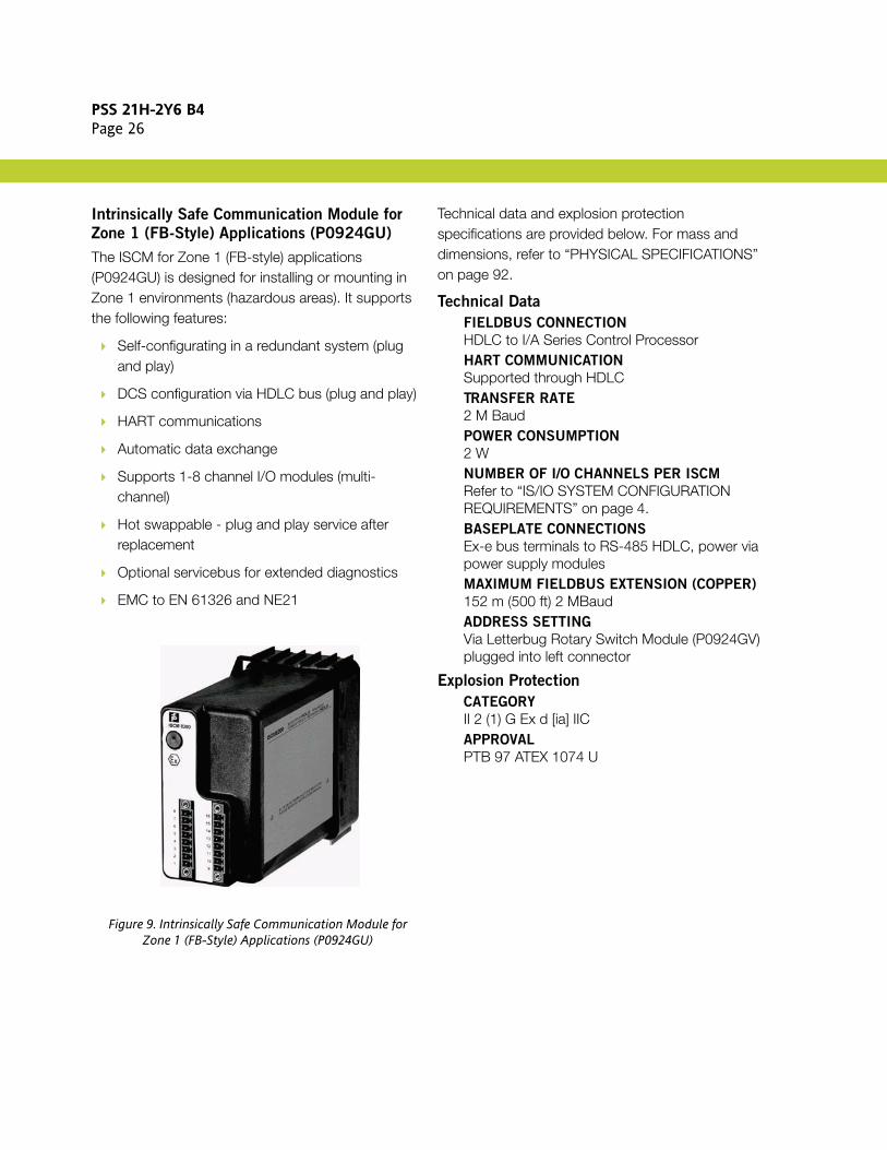
Intrinsically Safe Communication Module for
Zone 1 (FB-Style) Applications (P0924GU)
The ISCM for Zone 1 (FB-style) applications (P0924GU) is designed for installing or mounting in Zone 1 environments (hazardous areas). It supports the following features:
Self-configurating in a redundant system (plug and play)
DCS configuration via HDLC bus (plug and play)
HART communications
Automatic data exchange
Supports 1-8 channel I/O modules (multi-channel)
Hot swappable - plug and play service after replacement
Optional servicebus for extended diagnostics
EMC to EN 61326 and NE21
Figure 9. Intrinsically Safe Communication Module for Zone 1 (FB-Style) Applications (P0924GU)
Technical data and explosion protection specifications are provided below. For mass and dimensions, refer to “PHYSICAL SPECIFICATIONS” on page 92.
Technical Data
FIELDBUS CONNECTION
HDLC to I/A Series Control ProcessorHART COMMUNICATION
Supported through HDLCTRANSFER RATE
2 M BaudPOWER CONSUMPTION
2 WNUMBER OF I/O CHANNELS PER ISCM
Refer to “IS/IO SYSTEM CONFIGURATION REQUIREMENTS” on page 4.BASEPLATE CONNECTIONS
Ex-e bus terminals to RS-485 HDLC, power via power supply modulesMAXIMUM FIELDBUS EXTENSION (COPPER)
152 m (500 ft) 2 MBaudADDRESS SETTING
Via Letterbug Rotary Switch Module (P0924GV) plugged into left connector
Explosion Protection
CATEGORY
II 2 (1) G Ex d [ia] IICAPPROVAL
PTB 97 ATEX 1074 U

PSS 21H-2Y6 B4Page 27
Letterbug Rotary Switch Module (P0924GV)
The Letterbug Rotary Switch Module (P0924GV) has 16 positions (poles) and is plugged into the left-most receptacle on the front of the ISCM, and then screwed down to hold it in place. The fourth character of the ISCM letterbug must be selected by setting the rotary switch on the letterbug module. This character must match the fourth character of the FCM, if attached to an FCM.
Figure 10. Letterbug Rotary Switch Module (P0924GV)
NOTEThe intrinsic safety parameters for inductance and capacitance, refer to ATEX applications where both inductance and capacitance are present in the loop simultaneously. Improved values apply when one of the values is smaller than the one listed in the tables below.

PSS 21H-2Y6 B4Page 28
INVENSYS/P+F INTRINSICALLY SAFE MODULES SPECIFICATIONS
Specifications for the Pepperl+Fuchs intrinsically safe modules are provided below.
Pepperl+Fuchs intrinsically safe modules support the following features:
Hot swappable - plug and play service after replacement
Galvanic isolation between inputs and system/field bus
Line fault detection (LFD)
Permanently self-monitoring
EMC to EN 61326 or NE21
Input communications only
Their additional specifications are provided below.
LB 1101 A (Digital Input Module, Two Isolated
Channels)
The LB 1101 A digital input module is designed for Zone 2 environments and has inputs for contacts, NAMUR proximity switches and optocouplers.
Figure 11. LB 1101 A (Digital Input, Two Isolated Channels)
Inputs and explosion protection specifications are provided below.
Inputs
SIGNAL TYPE
Volt-free contacts and 2 wire NAMUR proximity switchesSWITCHING POINTS
On > 2.1 mAOff < 1.2 mAHYSTERESIS
0.2 mAMINIMUM PULSE DURATION
20 µsLINE FAULT (LFD)
≤ 0.05 mASHORT
≤ 100 ΩSCANNING TIME
6.5 msPOWER CONSUMPTION
Approximately 0.5 W
Explosion Protection
CATEGORY
II (1/2) G [Ex ia] IICAPPROVAL
PTB 03 ATEX 2042IIC SAFETY VALUES (LINEAR)
Uo ≤ 12.6 V Io ≤ 12.8 mA Po ≤ 40.1 mWCo ≤ 720 nF Lo ≤ 2 mH

PSS 21H-2Y6 B4Page 29
LB 1103 F (Frequency Input Module)
The LB 1103 F module supports frequency, and direction of rotation inputs. It is designed for Zone 2 environments and has inputs for contacts, NAMUR proximity switches and optocouplers.
Figure 12. LB 1103 F (Frequency Input Module)
Inputs and explosion protection specifications are provided below.
Inputs
SIGNAL TYPE
Volt-free contacts and 2 wire NAMUR proximity switchesSWITCHING POINTS
On > 2.1 mAOff < 1.2 mAHYSTERESIS
0.2 mAFREQUENCY
0 - 15 kHzPROCESSING TIME
Approximately 50 ms mode dependentMINIMUM PULSE DURATION
20 µsLINE FAULT (LFD)
≤ 0.05 mASHORT
≤ 100 ΩSCANNING TIME
6.5 msPOWER CONSUMPTION
Approximately 0.6 W
Explosion Protection
CATEGORY
II (1/2) G [Ex ia] IICAPPROVAL
PTB 03 ATEX 2042IIC SAFETY VALUES (LINEAR)
Uo ≤ 10.5 V Io ≤ 23.3 mA Po ≤ 61.2mWCo ≤ 816 nF Lo ≤ 2 mH

PSS 21H-2Y6 B4Page 30
LB 1103 FL (Low Frequency Input Module)
The LB 1103 FL module supports low frequency, and direction of rotation inputs. It is designed for Zone 2 environments and has inputs for contacts, NAMUR proximity switches and optocouplers.
Figure 13. LB 1103 FL (Low Frequency Input I/O Module)
Inputs and explosion protection specifications are provided below.
Inputs
SIGNAL TYPE
Volt-free contacts and 2 wire NAMUR proximity switchesSWITCHING POINTS
On > 2.1 mAOff < 1.2 mAHYSTERESIS
0.2 mAFREQUENCY
0 - 300 HzPROCESSING TIME
Approximately 50 ms mode dependentMINIMUM PULSE DURATION
1 msLINE FAULT (LFD)
≤ 0.05 mASHORT
≤ 100 ΩSCANNING TIME
6.5 msPOWER CONSUMPTION
Approximately 0.6 W
Explosion Protection
CATEGORY
II (1/2) G [Ex ia] IICAPPROVAL
PTB 03 ATEX 2042IIC SAFETY VALUES (LINEAR)
Uo ≤ 10.5 V Io ≤ 23.3 mA Po ≤ 61.2mWCo ≤ 816 nF Lo ≤ 2 mH

PSS 21H-2Y6 B4Page 31
LB 1104 F (Pulse Count Input Module)
The LB 1104 F module supports counter (pulse count) and up/down counting inputs. It is designed for Zone 2 environments and has inputs for contacts, NAMUR proximity switches and optocouplers.
Figure 14. LB 1104 F (Pulse Count Input Module)
Inputs and explosion protection specifications are provided below.
Inputs
SIGNAL TYPE
Volt-free contacts and 2 wire NAMUR proximity switchesSWITCHING POINTS
On > 2.1 mAOff < 1.2 mAHYSTERESIS
0.2 mAFREQUENCY
0 - 15 kHzCOUNTER
16 BitPROCESSING TIME
Approximately 50 ms mode dependentMINIMUM PULSE DURATION
20 µsLINE FAULT (LFD)
≤ 0.05 mASHORT
≤ 100 ΩSCANNING TIME
6.5 msPOWER CONSUMPTION
Approximately 0.6 W
Explosion Protection
CATEGORY
II (1/2) G [Ex ia] IICAPPROVAL
PTB 03 ATEX 2042IIC SAFETY VALUES (LINEAR)
Uo ≤ 10.5 V Io ≤ 23.3 mA Po ≤ 61.2mWCo ≤ 816 nF Lo ≤ 2 mH

PSS 21H-2Y6 B4Page 32
LB 1104 FL (Low Frequency Pulse Count Input
Module)
The LB 1104 FL module supports low frequency counter (pulse count) and up/down counting inputs. It is designed for Zone 2 environments and has inputs for contacts, NAMUR proximity switches and optocouplers.
Figure 15. LB 1104 FL (Low Frequency Pulse Count Module)
Inputs and explosion protection specifications are provided below.
Inputs
SIGNAL TYPE
Volt-free contacts and 2 wire NAMUR proximity switchesSWITCHING POINTS
On > 2.1 mAOff < 1.2 mAHYSTERESIS
0.2 mAFREQUENCY
0 - 300HzCOUNTER
16 BitPROCESSING TIME
Approximately 50 ms mode dependentMINIMUM PULSE DURATION
1 msLINE FAULT (LFD)
≤ 0.05 mASHORT
≤ 100 ΩSCANNING TIME
6.5 msPOWER CONSUMPTION
Approximately 0.6 W
Explosion Protection
CATEGORY
II (1/2) G [Ex ia] IICAPPROVAL
PTB 03 ATEX 2042IIC SAFETY VALUES (LINEAR)
Uo ≤ 10.5 V Io ≤ 23.3 mA Po ≤ 61.2mWCo ≤ 816 nF Lo ≤ 2 mH

PSS 21H-2Y6 B4Page 33
LB 1108 A (Digital Input Module, 8-Channels)
The LB 1108 A digital input module is designed for Zone 2 environments and has inputs for contacts, NAMUR proximity switches and optocouplers.
Figure 16. LB 1108 A (Digital Input Module, 8-Channels)
Inputs and explosion protection specifications are provided below.
Inputs
SIGNAL TYPE
Volt-free contacts and 2 wire NAMUR proximity switchesSWITCHING POINTS
On > 2.1 mAOff < 1.2 mAHYSTERESIS
0.2 mAMINIMUM PULSE DURATION
1 msLINE FAULT (LFD)
≤ 0.05 mASHORT
≤ 100 ΩSCANNING TIME
6.5 msPOWER CONSUMPTION
Approximately 0.7 W
Explosion Protection
CATEGORY
II (1/2) G [Ex ia] IICAPPROVAL
PTB 03 ATEX 2042IIC SAFETY VALUES (LINEAR)
Uo ≤ 15.3 V Io ≤ 16.1 mA Po ≤ 61.8 mWCo ≤ 450 nF Lo ≤ 2 mH

PSS 21H-2Y6 B4Page 34
LB 2101 A - LB 2113 A (Digital Output
Modules with Position Feedback)
The Digital Output Modules with Position Feedback (LB 2101 A - LB 2113 A - see Table 10 and Table 11) are designed for Zone 2 environments. They have two digital inputs for contacts, NAMUR proximity switches and optocouplers. Their digital outputs drive intrinsic safety solenoid valves, indicators or sounders.
Figure 17. LB 2101 A - LB 2113 A (Digital Output Modules with Position Feedback)
Inputs and explosion protection specifications are provided below.
Inputs
SIGNAL TYPE
Volt-free contacts and 2 wire proximity switches acc. to DIN19234 or NAMURSWITCHING POINTS
On > 2.1 mAOff < 1.2 mAHYSTERESIS
0.2 mAMINIMUM PULSE DURATION
1 msLINE FAULT (LFD)
≤ 0.05 mASHORT
≤ 100 ΩOUTPUT
Short circuit protectedWATCHDOG
OSS 0.5 seconds after serious faultPOWER CONSUMPTION
Approximately 0.52 W to 1.8 W depending on version
Explosion Protection
CATEGORY
II (1/2) G [Ex ia] IICAPPROVAL
PTB 03 ATEX 2042IIC SAFETY VALUES (LINEAR)
Sensor CircuitUo ≤ 14 V Io ≤ 16 mA Po ≤ 55 mWCo ≤ 418 nF Lo ≤ 5 mH
Output CircuitSee Table 10 and Table 11 below.

PSS 21H-2Y6 B4Page 35
Table 10. LB 2101 A - LB 2113 A Model Variations
P/N Uout Ra/Ω Limit/mA LFD/Ω Uo/V Io/mA Po/mW Co/nF Lo/mH
LB 2101 A 22.0 315 50 20...2000 24.9 91 558 79 1
LB 2102 A 24.0 210 75 110...1200 27.8 183 1270 227 1.9(a)
(a) Only group IIB
LB 2103 A 24.0 360 50 70...2000 27.8 91.5 636 69 0.4
LB 2104 A 22.0 220 50 220...1300 24.2 145 872 92 0.27
LB 2105 A 22.8 290 50 150...2000 25.2 108 681 74 0.5
LB 2112 A 25.3 329 - 25-3500 27.8 108 751 81 0.19
LB 2113 A 26.7 509 - 40...7000 28.7 68 485 69 0.4
Table 11. LB 2101 E - LB 2112 E Model Variations with Bus Independent SIL 2 Shutdown
P/N Uout Ra/Ω Limit/mA LFD/Ω Uo/V Io/mA Po/mW Co/nF Lo/mH
LB 2101 E 22.0 315 50 20...2000 24.9 91 558 79 1
LB 2103 E 24.0 360 50 70...2000 27.8 91.5 636 69 0.4
LB 2105 E 22.8 290 50 150...2000 25.2 108 681 74 0.5
LB 2112 E 25.3 329 - 25-3500 27.8 108 751 81 0.19

PSS 21H-2Y6 B4Page 36
LB 3102 A (HART Analog Input Module with
Transmitter Power Supply)
The LB 3102 A HART analog input module is designed for Zone 2 environments and has an input isolator for separately powered HART devices and a power supply for 2-wire HART transmitters.
Figure 18. LB 3102 A (HART Analog Input Module with Transmitter Power Supply)
Inputs and explosion protection specifications are provided below.
Inputs
FIELD DEVICE POWER SUPPLY
16.5 V (20 mA) incl. 250 ΩINPUT RANGE
4 - 20 mA (0 - 26 mA) HARTINPUT IMPEDANCE
15 Ω (at 5 - 6), 236 Ω (at 1- 6 HART)INTERNAL IMPEDANCE (TERMINAL 2-5)
315 ΩLINEARITY
< 0.1%TEMPERATURE DRIFT
< 0.1% / 10 KLINE MONITOR
Min. 0.5 mAMax. 22 mACONVERSION TIME
≤ 50 msec.POWER CONSUMPTION
1.2 W
Explosion Protection
CATEGORY
II (1/2) G [Ex ia] IICAPPROVAL
PTB 03 ATEX 2042IIC SAFETY VALUES (LINEAR)
Uo ≤ 27 V Io ≤ 92 mA Po ≤ 619 mWCo ≤ 73 nF Lo ≤ 0.4 mHIIC SAFETY VALUES (TRAPEZE RI = 8.28 K)
FOR INPUT 5-6
Uo ≤ 0.7 V Io ≤ 3 mA Po ≤ 2 mWCo ≤ 53 µF Lo ≤ 50 mH Ci ≤ 1.65 nFIIC SAFETY VALUES (TRAPEZE RI = 447 Ω)
FOR INPUT 1-6
Uo ≤ 8.2 V Io ≤ 56 mA Po ≤ 310 mWCo ≤ 1.1 µF Lo ≤ 1 mH Ci ≤ 1.65 nF
PSS 21H-2Y6 B4Page 37
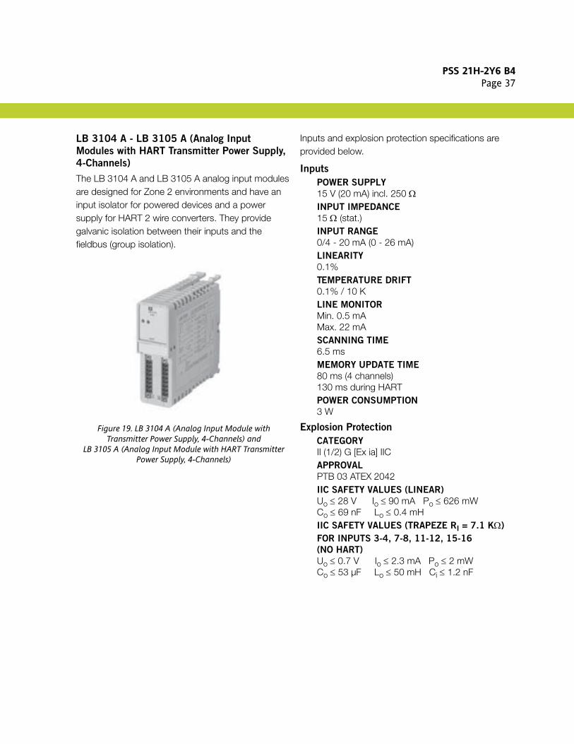
LB 3104 A - LB 3105 A (Analog Input
Modules with HART Transmitter Power Supply,
4-Channels)
The LB 3104 A and LB 3105 A analog input modules are designed for Zone 2 environments and have an input isolator for powered devices and a power supply for HART 2 wire converters. They provide galvanic isolation between their inputs and the fieldbus (group isolation).
Figure 19. LB 3104 A (Analog Input Module with Transmitter Power Supply, 4-Channels) and
LB 3105 A (Analog Input Module with HART Transmitter Power Supply, 4-Channels)
Inputs and explosion protection specifications are provided below.
Inputs
POWER SUPPLY
15 V (20 mA) incl. 250 ΩINPUT IMPEDANCE
15 Ω (stat.)INPUT RANGE
0/4 - 20 mA (0 - 26 mA)LINEARITY
0.1%TEMPERATURE DRIFT
0.1% / 10 KLINE MONITOR
Min. 0.5 mAMax. 22 mASCANNING TIME
6.5 msMEMORY UPDATE TIME
80 ms (4 channels)130 ms during HARTPOWER CONSUMPTION
3 W
Explosion Protection
CATEGORY
II (1/2) G [Ex ia] IICAPPROVAL
PTB 03 ATEX 2042IIC SAFETY VALUES (LINEAR)
Uo ≤ 28 V Io ≤ 90 mA Po ≤ 626 mWCo ≤ 69 nF Lo ≤ 0.4 mHIIC SAFETY VALUES (TRAPEZE RI = 7.1 KΩ)
FOR INPUTS 3-4, 7-8, 11-12, 15-16
(NO HART)
Uo ≤ 0.7 V Io ≤ 2.3 mA Po ≤ 2 mWCo ≤ 53 µF Lo ≤ 50 mH Ci ≤ 1.2 nF

PSS 21H-2Y6 B4Page 38
LB 4102 A - LB 4102 C (HART Analog Output
Modules)
The LB 4102 A and LB 4102 C HART analog output modules are designed for Zone 2 environments and have an output isolator for HART 4-20 mA signals, indicators, positioners, and I/P converters. They provide galvanic isolation between their outputs and the fieldbus.
Figure 20. LB 4102 A (HART Analog Output Module) andLB 4102 C (HART Analog Output Module with Bus
Independent SIL 2 Shutdown)
Outputs and explosion protection specifications are provided below.
Outputs
MAXIMUM LOAD
750 ΩOUTPUT CURRENT
0/4 - 20 mA (short circuit protected)IMIN/MAX
0/25 mA (1 mA for LFD)LINEARITY
< 0.1%CONVERSION TIME
≤ 50 msec.TEMPERATURE DRIFT
< 0.1% / 10 KLINE MONITOR
> 850 Ω ... 4 kΩWATCHDOG CIRCUIT
Output OFF 0.5 sec. after serious faultsPOWER CONSUMPTION
0.8 W
Explosion Protection
CATEGORY
II (1/2) G [Ex ia] IICAPPROVAL
PTB 03 ATEX 2042IIC SAFETY VALUES (LINEAR)
Uo ≤ 27.3 V Io ≤ 87 mA Po ≤ 595 mWCo ≤ 72 nF Lo ≤ 0.4 mH

PSS 21H-2Y6 B4Page 39
LB 4104 A - LB 4105 D (HART Analog Output
Modules, 4-Channels)
The LB 4104 A analog output module, and the LB 4105 C and LB 4105 D HART analog output modules are designed for Zone 2 environments and have an output isolator for indicators, displays, IP converters, positioners, and valves. They provide galvanic isolation between their outputs and the fieldbus (group isolation).
Figure 21. LB 4104 A (Analog Output Module, 4-Channels) and LB 4105 D (HART Analog Output Module, 4-Channels
with Line Monitor)
Outputs and explosion protection specifications are provided below.
Outputs
MAXIMUM LOAD
750 ΩOUTPUT CURRENT
4 - 20 mA (0 - 25 mA) short protectedLINEARITY
0.1%TEMPERATURE DRIFT
0.1% / 10 KLINE MONITOR
Min. 0.5 mATHRESHOLD
> 850 ΩWATCHDOG CIRCUIT
Output OFF 0.5 sec. after serious faultsSCANNING TIME
6.5 msMEMORY UPDATE TIME
58 ms (4-channels)110 ms (during HART communications)POWER CONSUMPTION
3 W
Explosion Protection
CATEGORY
II (1/2) G [Ex ia] IICAPPROVAL
PTB 03 ATEX 2042IIC SAFETY VALUES (LINEAR)
Uo ≤ 27.3 V Io ≤ 93 mA Po ≤ 635 mWCo ≤ 74 nF Lo ≤ 0.4 mH

PSS 21H-2Y6 B4Page 40
LB 5101 F3 (2 or 3-Wire RTD Input Module)
The LB 5101 F3 RTD input module supports 2 or 3-wire RTD (temperature) inputs. It is designed for Zone 2 environments.
Figure 22. LB 5101 F3 (2 or 3-Wire RTD Input Module)
Inputs and explosion protection specifications are provided below.
Inputs
RANGE
0-320 ΩWIRE RESISTANCE
50 Ω maximum each wireRTD LINE FAULT (LFD)
> 500 ΩLINEARITY
< 0.02 %TEMPERATURE DRIFT
< 0.02 %/10 KSENSOR CURRENT
200 µACONVERSION TIME
< 150 ms with LFDPOWER CONSUMPTION
Approximately 0.45 W
Explosion Protection
CATEGORY
II (1/2) G [Ex ia] IICAPPROVAL
PTB 03 ATEX 2042IIC SAFETY VALUES (TRAPEZE RI = 330Ω)
Uo ≤ 2.7 V Io ≤ 43 mA Po ≤ 93 mWCo ≤ 3 µF Lo ≤ 10 mH Ci ≤ 1.25 µF

PSS 21H-2Y6 B4Page 41
LB 5101 F4 (4-Wire RTD Input Module)
The LB 5101 F4 module supports 4-wire RTD (temperature) inputs. It is designed for Zone 2 environments.
Figure 23. LB 5101 F4 (4-Wire RTD Input Module)
Inputs and explosion protection specifications are provided below.
Inputs
RANGE
0-320 ΩWIRE RESISTANCE
50 Ω maximum each wireRTD LINE FAULT (LFD)
> 500 ΩLINEARITY
< 0.02 %TEMPERATURE DRIFT
< 0.02 %/10 KSENSOR CURRENT
200 µACONVERSION TIME
< 150 ms with LFDPOWER CONSUMPTION
Approximately 0.45 W
Explosion Protection
CATEGORY
II (1/2) G [Ex ia] IICAPPROVAL
PTB 03 ATEX 2042IIC SAFETY VALUES (TRAPEZE RI = 330Ω)
Uo ≤ 2.7 V Io ≤ 43 mA Po ≤ 93 mWCo ≤ 3 µF Lo ≤ 10 mH Ci ≤ 1.25 µF

PSS 21H-2Y6 B4Page 42
LB 5102 F (Thermocouple Input Module)
The LB 5102 F module supports thermocouple or mV inputs with cold junction compensation. It is designed for Zone 2 environments.
Figure 24. LB 5102 F (Thermocouple Input Module)
Inputs and explosion protection specifications are provided below.
Inputs
RANGE
E.G. TYPE U, B, E, T, K, S, R, L, J, N, PALLAPLATMEASURING RANGE
-10.5 MV .... + 69.5 MVCOMPENSATION
INTERNAL (AT CONNECTOR) OR EXTERNALCJC PT100 SENSOR CURRENT
200 µACONVERSION TIME FOR INTERNAL CJC
< 250 MS WITH LFDLINEARITY
< 0.007 %TEMPERATURE DRIFT
< 0.02 %/10 KLINE FAULT (LFD)
> 1 KΩPOWER CONSUMPTION
APPROXIMATELY 0.45 W
Explosion Protection
CATEGORY
II (1/2) G [EX IA] IICAPPROVAL
PTB 03 ATEX 2042IIC SAFETY VALUES (TRAPEZE RI = 330Ω)
UO ≤ 1.8 V IO ≤ 43 MA PO ≤ 67 MWCO ≤ 8.7 µF LO ≤ 10 MH CI ≤ 100 NF

PSS 21H-2Y6 B4Page 43
LB 5104 F3 (2 or 3-Wire RTD Input Module,
4-Channels)
The LB 5104 F3 module supports 2 or 3-wire RTD or slide wire sensor inputs (with four channels). It is designed for Zone 2 environments and it has group isolation.
Figure 25. LB 5104 F3 (2 or 3-Wire RTD Input Module,4-Channels)
Inputs and explosion protection specifications are provided below.
Inputs
RTD RANGE
0-320 ΩSLIDE WIRE SENSORS
0-320 ΩSENSOR CURRENT
< 0.22 mAWIRE RESISTANCE
< 50 Ω each wireLINE BREAK DETECTION
> 1 kΩNONLINEARITY
0.02%TEMPERATURE DRIFT
0.02%/10 KSCAN TIME
6.5 msCONVERSION TIME
< 1000 ms (4 channels)CONNECTION
Screw plug-in or wire clamp connectorsPOWER CONSUMPTION
Approximately 0.6W
Explosion Protection
CATEGORY
II (1/2) G [Ex ia] IICAPPROVAL
PTB 03 ATEX 2042IIC SAFETY VALUES (TRAPEZE RI = 103Ω)
Uo ≤ 6.8 V Io ≤ 70 mA Po ≤ 118 mWCo ≤ 1 µF Lo ≤ 5 mH Ci ≤ 100 nF

PSS 21H-2Y6 B4Page 44
LB 5104 F4 (4-Wire RTD Input Module,
4-Channels)
The LB 5104 F4 module supports 4-wire RTD inputs. It is designed for Zone 2 environments and it has group isolation.
Figure 26. LB 5104 F4 (4-Wire RTD Input Module,4-Channels)
Inputs and explosion protection specifications are provided below.
Inputs
RTD RANGE
0-320 ΩSENSOR CURRENT
< 0.22 mAWIRE RESISTANCE
< 50 Ω each wireLINE BREAK DETECTION
> 1 kΩ (break)NONLINEARITY
0.025%TEMPERATURE DRIFT
0.025%/10 KSCAN TIME
6.5 msCONVERSION TIME
< 500 ms (4 channels)CONNECTION
Screw plug-in or wire clamp connectorsPOWER CONSUMPTION
Approximately 0.6W
Explosion Protection
CATEGORY
II (1/2) G [Ex ia] IICAPPROVAL
PTB 03 ATEX 2042IIC SAFETY VALUES (TRAPEZE RI = 103Ω)
Uo ≤ 6.8 V Io ≤ 70 mA Po ≤ 118 mWCo ≤ 1 µF Lo ≤ 5 mH
PSS 21H-2Y6 B4Page 45
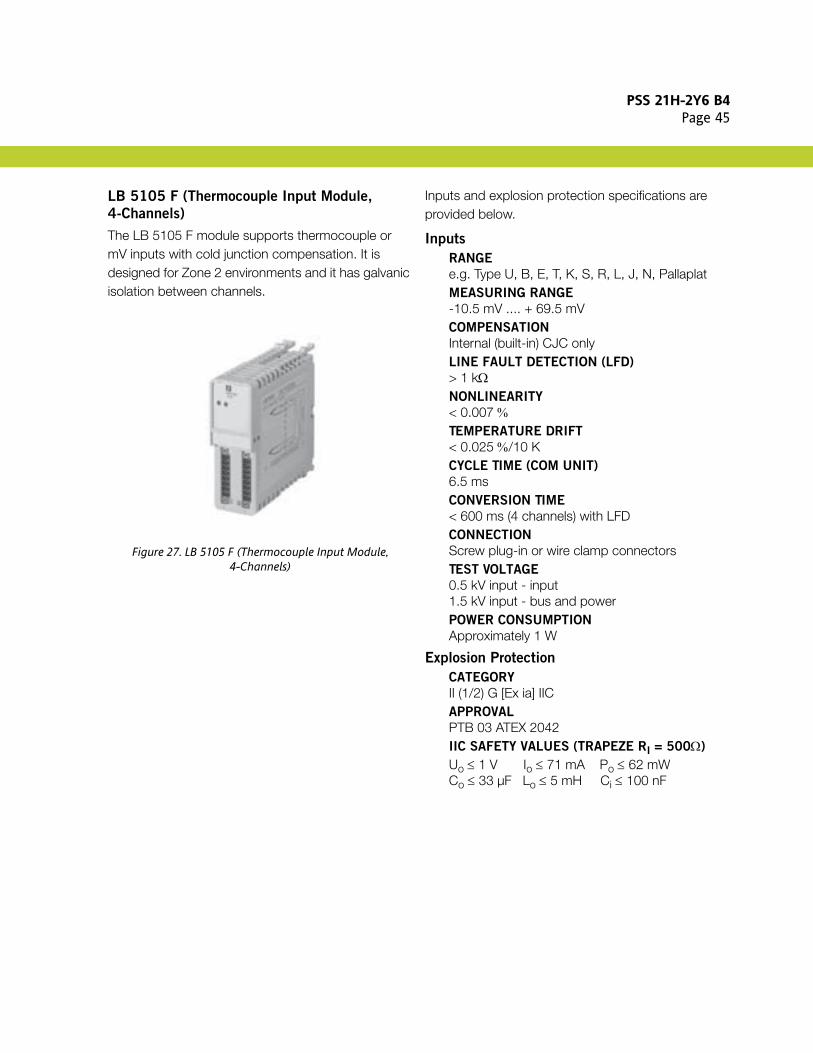
LB 5105 F (Thermocouple Input Module,
4-Channels)
The LB 5105 F module supports thermocouple or mV inputs with cold junction compensation. It is designed for Zone 2 environments and it has galvanic isolation between channels.
Figure 27. LB 5105 F (Thermocouple Input Module,4-Channels)
Inputs and explosion protection specifications are provided below.
Inputs
RANGE
e.g. Type U, B, E, T, K, S, R, L, J, N, PallaplatMEASURING RANGE
-10.5 mV .... + 69.5 mVCOMPENSATION
Internal (built-in) CJC onlyLINE FAULT DETECTION (LFD)
> 1 kΩNONLINEARITY
< 0.007 %TEMPERATURE DRIFT
< 0.025 %/10 KCYCLE TIME (COM UNIT)
6.5 msCONVERSION TIME
< 600 ms (4 channels) with LFDCONNECTION
Screw plug-in or wire clamp connectorsTEST VOLTAGE
0.5 kV input - input1.5 kV input - bus and powerPOWER CONSUMPTION
Approximately 1 W
Explosion Protection
CATEGORY
II (1/2) G [Ex ia] IICAPPROVAL
PTB 03 ATEX 2042IIC SAFETY VALUES (TRAPEZE RI = 500Ω)
Uo ≤ 1 V Io ≤ 71 mA Po ≤ 62 mWCo ≤ 33 µF Lo ≤ 5 mH Ci ≤ 100 nF

PSS 21H-2Y6 B4Page 46
LB 5106 A (Voltage Converter Module)
The LB 5106 A voltage converter module supports inputs for 0-10V input signals. It is designed for Zone 2 environments and it provides galvanic isolation between its input and the fieldbus.
Figure 28. LB 5106 A (Voltage Converter Module)
Inputs and explosion protection specifications are provided below.
Inputs
RANGE
0 - +10 VINPUT IMPEDANCE
100 kΩLINE FAULT DETECTION (LFD)
None LINEARITY
< 0,1% TypicalTEMPERATURE DRIFT
< 0.1% / 10 KCONVERSION TIME
100 msPOWER CONSUMPTION
< 0.45 W
Explosion Protection
CATEGORY
II (1/2) G [Ex ia] IICAPPROVAL
PTB 03 ATEX 2042IIC SAFETY VALUES (LINEAR)
Uo ≤ 0.9 V Io ≤ 0.2 mA Po ≤ 0.2 mWCo ≤ 53 µF Lo ≤ 100 mH Ci ≤ 52 nF

PSS 21H-2Y6 B4Page 47
LB 6005 A (Digital Relay Output Module,
4-Channels)
The LB 6005 A digital relay output module is designed for Zone 2 environments and supports outputs with relay-contacts for LEDs, annunciators and valves. It provides galvanic isolation between its outputs.
Figure 29. LB 6005 A (Digital Relay Output Module,4-Channels)
Outputs and explosion protection specifications are provided below.
Outputs
RELAY CONTACT/CHANNEL
20 V dc, 1 A, 30 W (resistive load)230 V ac, 1 A, 250 vA (resistive load)CONTACT MATERIAL
AgPd gold platedELECTRICAL LIFETIME
0.1 Mio. cyclesMIN. SWITCHING CAPABILITY
> 1 V, > 1 mARESPONSE TIME
Approximately 20 ms (depending on bus cycle time)SCANNING TIME
6.5 msWATCHDOG CIRCUIT
Relay OFF 0.5 sec. after serious faultsPOWER CONSUMPTION
1.2 W
Explosion Protection
CATEGORY
II 3 G Ex nA CII T4APPROVAL
PF 08 CERT 1234

PSS 21H-2Y6 B4Page 48
LB 6006 A (Digital Relay Output Module,
8-Channels)
The LB 6006 A digital relay output module is designed for Zone 2 environments and supports outputs with relay-contacts for LEDs, annunciators or valves. It provides galvanic isolation between its outputs.
Figure 30. LB 6006 A (Digital Relay Output Module,8-Channels)
Outputs and explosion protection specifications are provided below.
Outputs
RELAY CONTACT/CHANNEL
24 V ac/dc, 1 A, 30 W, 30 vA (resistive load)CONTACT MATERIAL
AgPd gold platedELECTRICAL LIFETIME
0.5 Mio. cyclesMIN. SWITCHING CAPABILITY
> 1 V, > 1 mARESPONSE TIME
Approximately 20 ms (depending on bus cycle time)SCANNING TIME
6.5 msWATCHDOG CIRCUIT
Relay OFF 0.5 sec. after serious faultsCONNECTION
Screw plug-in or wire clampPOWER CONSUMPTION
1.6 W
Explosion Protection
CATEGORY
II 3 G Ex nA CII T4APPROVAL
PF 08 CERT 1234
PSS 21H-2Y6 B4Page 49
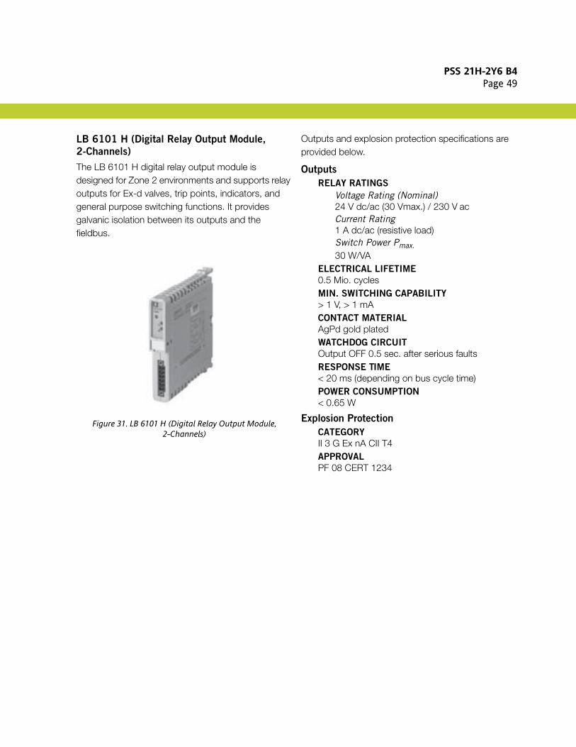
LB 6101 H (Digital Relay Output Module,
2-Channels)
The LB 6101 H digital relay output module is designed for Zone 2 environments and supports relay outputs for Ex-d valves, trip points, indicators, and general purpose switching functions. It provides galvanic isolation between its outputs and the fieldbus.
Figure 31. LB 6101 H (Digital Relay Output Module,2-Channels)
Outputs and explosion protection specifications are provided below.
Outputs
RELAY RATINGS
Voltage Rating (Nominal)24 V dc/ac (30 Vmax.) / 230 V acCurrent Rating1 A dc/ac (resistive load)Switch Power Pmax.30 W/VA
ELECTRICAL LIFETIME
0.5 Mio. cyclesMIN. SWITCHING CAPABILITY
> 1 V, > 1 mACONTACT MATERIAL
AgPd gold platedWATCHDOG CIRCUIT
Output OFF 0.5 sec. after serious faultsRESPONSE TIME
< 20 ms (depending on bus cycle time)POWER CONSUMPTION
< 0.65 W
Explosion Protection
CATEGORY
II 3 G Ex nA CII T4APPROVAL
PF 08 CERT 1234

PSS 21H-2Y6 B4Page 50
LB 6108 A (Digital Output Module,
8-Channels, Low Power)
The LB 6108 A digital output module is designed for Zone 2 environments and supports active 20 V outputs to switch LEDs, indicators, or low power solenoid valves. It provides galvanic isolation between its outputs and the fieldbus (group isolation).
Figure 32. LB 6108 A (Digital Output Module, 8-Channels, Low Power)
Outputs and explosion protection specifications are provided below.
Outputs
DIGITAL OUTPUT (ACTIVE/SHORT
PROTECTED)
20 V, 8 mA per channel (model LB 6108 A)21.6 V/5.2 mA (model LB 6108 C)SCANNING TIME
6.5 msLFD TEST CURRENT
0.33 mAWATCHDOG CIRCUIT
Output volt-free 0.5 sec. after serious faultsPOWER CONSUMPTION
2.2 W
Explosion Protection
CATEGORY
II (2) G [Ex ib] IICAPPROVAL
PTB 03 ATEX 2042IIC SAFETY VALUES (RECTANGULAR) MODEL
A6108
Uo ≤ 28 V Io ≤ 13.5 mA Po ≤ 376 mWCo ≤ 76 nF Lo ≤ 0.5 mHIIC SAFETY VALUES (RECTANGULAR) MODEL
C6108
Uo ≤ 30 V Io ≤ 13.5 mA Po ≤ 404 mWCo ≤ 62 nF Lo ≤ 0.5 mH

PSS 21H-2Y6 B4Page 51
LB 6110 A - LB 6115 ES (Digital Output
Module, 4-Channels, Intrinsically Safe Power)
The LB 6110 A to LB 6115 ES digital output modules are designed for Zone 2 environments and support outputs for intrinsically safe solenoid valves, and for sounders and LEDs. They provide galvanic isolation between their outputs and the fieldbus (group isolation).
Figure 33. LB 6110 A - LB 6115 ES (Digital Output Module, 4-Channels, Intrinsically Safe Power)
Power supply, outputs and explosion protection specifications are provided below.
Power Supply
EXTERNAL POWER
24 V dc, 5 W via Booster connection on backplanes LB 9022, 9023, ..25, ..26, ..27, ..29
Outputs
DRIVE CAPABILITY
See Table 12 and Table 13 below.LINE MONITOR (2MS TEST PULSE)
Every 2.5 sec (LFD)LFD REACTION TIME
10 s (worst case)OUTPUT RESPONSE TIME
> 10 ms (depending on the master)SCAN RATE
6.5 msWATCHDOG CIRCUIT
Output OFF 0.5 sec. after serious faultsCONNECTION
Screw plug-in or wire clamp connectorsPOWER CONSUMPTION
0.6 W
Explosion Protection
CATEGORY
II (2/1) G [Ex ia/ib] IICAPPROVAL
PTB 03 ATEX 2042SAFETY VALUES
See Table 12 and Table 13 below.

PSS 21H-2Y6 B4Page 52
Table 12. LB 6110 A - LB 6115 A Model Variations
P/N U/V Ra/Ω Limit/mA LFD/Ω Uo/V Io/mA Po/mW Co/nF Lo/mH
LB 6110 A 24.5 370 55 90 ... 12000 27.8 90.4 629 81 0.2
LB 6111 A 24.5 320 60 110 ... 12000 27.8 107 744 81 0.2
LB 6112 A 17.0 185 70 95 ... 8000 19.8 142 705 117 0.5
LB 6113 A 23.0 290 60 110 ... 10000 26 110 714 96 0.2
LB 6114 A 23.0 355 55 90 ... 10000 26 88.7 578 96 0.2
LB 6115 A 16.2 78 80 100 ... 8500 18.9 286 1350 150 0.17
Table 13. LB 6110 E - LB 6115 ES Model Variations
P/N U/V Ra/Ω Limit/mA LFD/Ω Uo/V Io/mA Po/mW Co/nF Lo/mH
LB 6110 E 24.5 370 55 90 ... 12000 27.8 90.4 629 81 0.2
LB 6111 E 24.5 320 60 110 ... 12000 27.8 107 744 81 0.2
LB 6112 E 17.0 185 70 95 ... 8000 19.8 142 705 117 0.5
LB 6113 E 23.0 290 60 110 ... 10000 26 110 714 96 0.2
LB 6114 E 23.0 355 55 90 ... 10000 26 88.7 578 96 0.2
LB 6115 ES 16.2 78 80 100 ... 8500 18.9 286 1350 150 0.17
PSS 21H-2Y6 B4Page 53
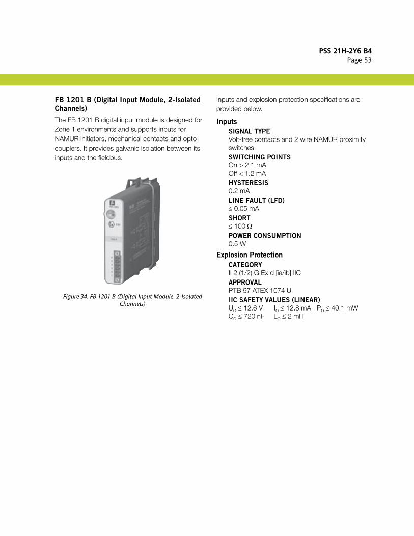
FB 1201 B (Digital Input Module, 2-Isolated
Channels)
The FB 1201 B digital input module is designed for Zone 1 environments and supports inputs for NAMUR initiators, mechanical contacts and opto-couplers. It provides galvanic isolation between its inputs and the fieldbus.
Figure 34. FB 1201 B (Digital Input Module, 2-Isolated Channels)
Inputs and explosion protection specifications are provided below.
Inputs
SIGNAL TYPE
Volt-free contacts and 2 wire NAMUR proximity switchesSWITCHING POINTS
On > 2.1 mAOff < 1.2 mAHYSTERESIS
0.2 mALINE FAULT (LFD)
≤ 0.05 mASHORT
≤ 100 ΩPOWER CONSUMPTION
0.5 W
Explosion Protection
CATEGORY
II 2 (1/2) G Ex d [ia/ib] IICAPPROVAL
PTB 97 ATEX 1074 UIIC SAFETY VALUES (LINEAR)
Uo ≤ 12.6 V Io ≤ 12.8 mA Po ≤ 40.1 mWCo ≤ 720 nF Lo ≤ 2 mH
PSS 21H-2Y6 B4Page 54
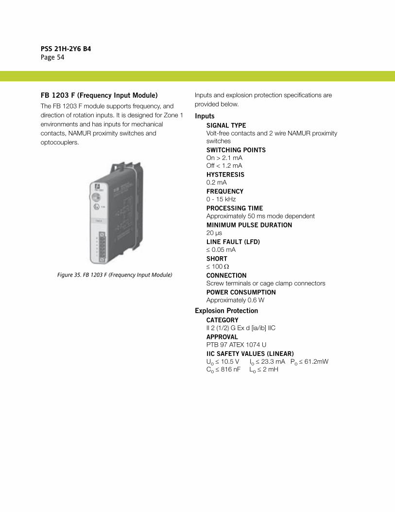
FB 1203 F (Frequency Input Module)
The FB 1203 F module supports frequency, and direction of rotation inputs. It is designed for Zone 1 environments and has inputs for mechanical contacts, NAMUR proximity switches and optocouplers.
Figure 35. FB 1203 F (Frequency Input Module)
Inputs and explosion protection specifications are provided below.
Inputs
SIGNAL TYPE
Volt-free contacts and 2 wire NAMUR proximity switchesSWITCHING POINTS
On > 2.1 mAOff < 1.2 mAHYSTERESIS
0.2 mAFREQUENCY
0 - 15 kHzPROCESSING TIME
Approximately 50 ms mode dependentMINIMUM PULSE DURATION
20 µsLINE FAULT (LFD)
≤ 0.05 mASHORT
≤ 100 ΩCONNECTION
Screw terminals or cage clamp connectorsPOWER CONSUMPTION
Approximately 0.6 W
Explosion Protection
CATEGORY
II 2 (1/2) G Ex d [ia/ib] IICAPPROVAL
PTB 97 ATEX 1074 UIIC SAFETY VALUES (LINEAR)
Uo ≤ 10.5 V Io ≤ 23.3 mA Po ≤ 61.2mWCo ≤ 816 nF Lo ≤ 2 mH

PSS 21H-2Y6 B4Page 55
FB 1203 FL (Low Frequency Input Module)
The FB 1203 FL module supports low frequency, and direction of rotation inputs. It is designed for Zone 1 environments and has inputs for mechanical contacts, NAMUR proximity switches and optocouplers.
Figure 36. FB 1203 FL (Low Frequency Input Module)
Inputs and explosion protection specifications are provided below.
Inputs
SIGNAL TYPE
Volt-free contacts and 2 wire NAMUR proximity switchesSWITCHING POINTS
On > 2.1 mAOff < 1.2 mAHYSTERESIS
0.2 mAFREQUENCY
0 - 300 HzPROCESSING TIME
Approximately 50 ms mode dependentMINIMUM PULSE DURATION
1 msLINE FAULT (LFD)
≤ 0.05 mASHORT
≤ 100 ΩCONNECTION
Screw terminals or cage clamp connectorsPOWER CONSUMPTION
Approximately 0.6 W
Explosion Protection
CATEGORY
II 2 (1/2) G Ex d [ia/ib] IICAPPROVAL
PTB 97 ATEX 1074 UIIC SAFETY VALUES (LINEAR)
Uo ≤ 10.5 V Io ≤ 23.3 mA Po ≤ 61.2mWCo ≤ 816 nF Lo ≤ 2 mH
PSS 21H-2Y6 B4Page 56
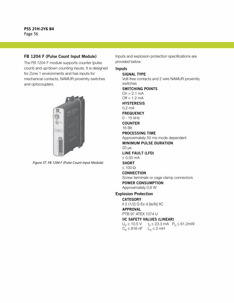
FB 1204 F (Pulse Count Input Module)
The FB 1204 F module supports counter (pulse count) and up/down counting inputs. It is designed for Zone 1 environments and has inputs for mechanical contacts, NAMUR proximity switches and optocouplers.
Figure 37. FB 1204 F (Pulse Count Input Module)
Inputs and explosion protection specifications are provided below.
Inputs
SIGNAL TYPE
Volt-free contacts and 2 wire NAMUR proximity switchesSWITCHING POINTS
On > 2.1 mAOff < 1.2 mAHYSTERESIS
0.2 mAFREQUENCY
0 - 15 kHzCOUNTER
16 BitPROCESSING TIME
Approximately 50 ms mode dependentMINIMUM PULSE DURATION
20 µsLINE FAULT (LFD)
≤ 0.05 mASHORT
≤ 100 ΩCONNECTION
Screw terminals or cage clamp connectorsPOWER CONSUMPTION
Approximately 0.6 W
Explosion Protection
CATEGORY
II 2 (1/2) G Ex d [ia/ib] IICAPPROVAL
PTB 97 ATEX 1074 UIIC SAFETY VALUES (LINEAR)
Uo ≤ 10.5 V Io ≤ 23.3 mA Po ≤ 61.2mWCo ≤ 816 nF Lo ≤ 2 mH

PSS 21H-2Y6 B4Page 57
FB 1204 FL (Low Frequency Pulse Count Input
Module)
The FB 1204 FL module supports low frequency counter (pulse count) and up/down counting inputs. It is designed for Zone 1 environments and has inputs for mechanical contacts, NAMUR proximity switches and optocouplers.
Figure 38. FB 1204 FL (Low Frequency Pulse Count Input Module)
Inputs and explosion protection specifications are provided below.
Inputs
SIGNAL TYPE
Volt-free contacts and 2 wire NAMUR proximity switchesSWITCHING POINTS
On > 2.1 mAOff < 1.2 mAHYSTERESIS
0.2 mAFREQUENCY
0 - 300 HzCOUNTER
16 BitPROCESSING TIME
Approximately 50 ms mode dependentMINIMUM PULSE DURATION
1 msLINE FAULT (LFD)
≤ 0.05 mASHORT
≤ 100 ΩCONNECTION
Screw terminals or cage clamp connectorsPOWER CONSUMPTION
Approximately 0.6 W
Explosion Protection
CATEGORY
II 2 (1/2) G Ex d [ia/ib] IICAPPROVAL
PTB 97 ATEX 1074 UIIC SAFETY VALUES (LINEAR)
Uo ≤ 10.5 V Io ≤ 23.3 mA Po ≤ 61.2mWCo ≤ 816 nF Lo ≤ 2 mH

PSS 21H-2Y6 B4Page 58
FB 1208 B (Digital Input Module, 8-Channels)
The FB 1208 B digital input module is designed for Zone 1 environments and has inputs for contacts, NAMUR-proximity switches and optocouplers. It provides galvanic isolation between its inputs and the fieldbus (group isolation).
Figure 39. FB 1208 B (Digital Input Module, 8-Channels)
Inputs and explosion protection specifications are provided below.
Inputs
SIGNAL TYPE
Volt-free contacts and 2 wire NAMUR proximity switchesSWITCHING POINTS
On > 2.1 mAOff < 1.2 mA1.65 mA +/– 0.25 mAHYSTERESIS
0.2 mALINE FAULT (LFD)
≤ 0.05 mASHORT
≤ 100 ΩSCANNING TIME
6.5 msPOWER CONSUMPTION
0.7 W
Explosion Protection
CATEGORY
II 2 (1/2) G Ex d [ia/ib] IICAPPROVAL
PTB 97 ATEX 1074 UIIC SAFETY VALUES (LINEAR)
Uo ≤ 15.3 V Io ≤ 16.1 mA Po ≤ 61.8 mWCo ≤ 450 nF Lo ≤ 2 mH

PSS 21H-2Y6 B4Page 59
FB 1301 B and FB 1301 B200 (Digital Input
Module, 2-Channels, Ex-e)
The FB 1301 B and FB 1301 B200 digital input modules are designed for Zone 1 environments and have inputs for contacts, NAMUR-proximity switches and optocouplers. They provide galvanic isolation between their inputs as well as their input and the fieldbus, and have Ex-e connections.
Figure 40. FB 1301 B (Digital Input Module, 2-Channels Ex-e)
Inputs and explosion protection specifications are provided below.
Inputs
SIGNAL TYPE
Volt-free contacts and 2 wire NAMUR proximity switchesSWITCHING POINTS
On > 2.1 mAOff < 1.2 mAHYSTERESIS
0.2 mALINE FAULT (LFD)
≤ 0.05 mASHORT
≤ 100 ΩSCANNING TIME
Approximately 6.5 msCONNECTION
FB 1301 BPlug-in Ex-e front connectors with IP30 hood; field wiring goes directly to the connector; connector and hood supplied with I/O module (recommended for new installations)
NOTEA hot work permit is required for access to the connector under the hood.
FB 1301 B2002 m cable tails to Ex-e terminals
POWER CONSUMPTION
0.5 W
Explosion Protection
CATEGORY
II 2 G Ex d IICAPPROVAL
PTB 97 ATEX 1074 U

PSS 21H-2Y6 B4Page 60
FB 1303 F and FB 1303 F2 (Frequency Ex-e
Input Module)
The FB 1303 F and FB 1303 F2 modules support frequency and direction of rotation inputs (1 channel, Ex-e). They are designed for Zone 1 environments and have inputs for contacts, NAMUR proximity switches and optocouplers. Access to Ex-e connections is possible when volt-free.
Figure 41. FB 1303 F (Frequency Ex-e Input Module)
Inputs and explosion protection specifications are provided below.
Inputs
SIGNAL TYPE
Volt-free contacts and 2 wire NAMUR proximity switchesSWITCHING POINTS
On > 2.1 mAOff < 1.2 mAHYSTERESIS
0.2 mAFREQUENCY
0 - 15 kHzPROCESSING TIME
Approximately 50 ms mode dependentMINIMUM PULSE DURATION
20 µsLINE FAULT (LFD)
≤ 0.05 mASHORT
≤ 100 ΩSCANNING TIME
Approximately 6.5 msCONNECTION
FB 1303 FPlug-in Ex-e front connectors with IP30 hood; field wiring goes directly to the connector; connector and hood supplied with I/O module (recommended for new installations)
NOTEA hot work permit is required for access to the connector under the hood.
FB 1303 F22 m cable tails to Ex-e terminals
POWER CONSUMPTION
0.6 W
Explosion Protection
CATEGORY
II 2 G Ex d IICAPPROVAL
PTB 97 ATEX 1074 U

PSS 21H-2Y6 B4Page 61
FB 1303 FL and FB 1303 FL2 (Low Frequency
Ex-e Input Module)
The FB 1303 FL and FB 1303 FL2 modules support low frequency and direction of rotation inputs (1 channel, Ex-e). They are designed for Zone 1 environments and have inputs for contacts, NAMUR proximity switches and optocouplers. Access to Ex-e connections is possible when volt-free.
Figure 42. FB 1303 FL (Low Frequency Ex-e Input Module)
Inputs and explosion protection specifications are provided below.
Inputs
SIGNAL TYPE
Volt-free contacts and 2 wire NAMUR proximity switchesSWITCHING POINTS
On > 2.1 mAOff < 1.2 mAHYSTERESIS
0.2 mAFREQUENCY
0 - 300 HzPROCESSING TIME
Approximately 50 ms mode dependentMINIMUM PULSE DURATION
1 msLINE FAULT (LFD)
≤ 0.05 mASHORT
≤ 100 ΩSCANNING TIME
Approximately 6.5 msCONNECTION
FB 1303 FLPlug-in Ex-e front connectors with IP30 hood; field wiring goes directly to the connector; connector and hood supplied with I/O module (recommended for new installations)
NOTEA hot work permit is required for access to the connector under the hood.
FB 1303 FL22 m cable tails to Ex-e terminals
POWER CONSUMPTION
0.6 W
Explosion Protection
CATEGORY
II 2 G Ex d IICAPPROVAL
PTB 97 ATEX 1074 U
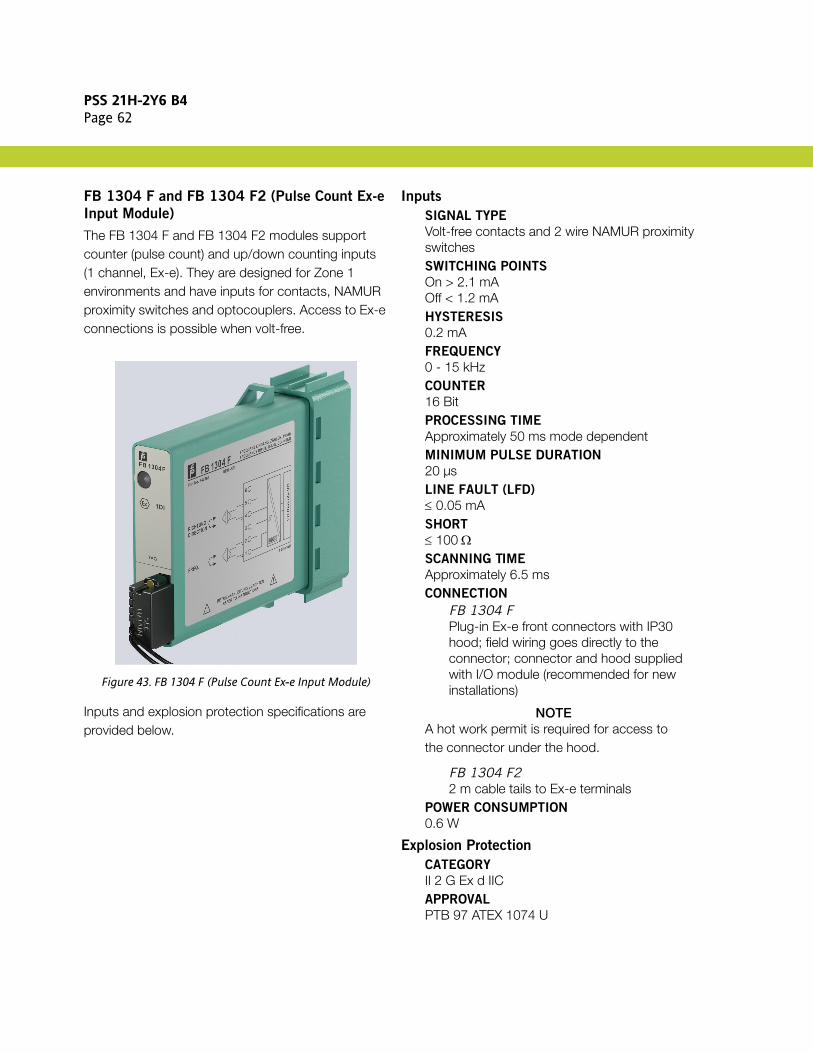
PSS 21H-2Y6 B4Page 62
FB 1304 F and FB 1304 F2 (Pulse Count Ex-e
Input Module)
The FB 1304 F and FB 1304 F2 modules support counter (pulse count) and up/down counting inputs (1 channel, Ex-e). They are designed for Zone 1 environments and have inputs for contacts, NAMUR proximity switches and optocouplers. Access to Ex-e connections is possible when volt-free.
Figure 43. FB 1304 F (Pulse Count Ex-e Input Module)
Inputs and explosion protection specifications are provided below.
Inputs
SIGNAL TYPE
Volt-free contacts and 2 wire NAMUR proximity switchesSWITCHING POINTS
On > 2.1 mAOff < 1.2 mAHYSTERESIS
0.2 mAFREQUENCY
0 - 15 kHzCOUNTER
16 BitPROCESSING TIME
Approximately 50 ms mode dependentMINIMUM PULSE DURATION
20 µsLINE FAULT (LFD)
≤ 0.05 mASHORT
≤ 100 ΩSCANNING TIME
Approximately 6.5 msCONNECTION
FB 1304 FPlug-in Ex-e front connectors with IP30 hood; field wiring goes directly to the connector; connector and hood supplied with I/O module (recommended for new installations)
NOTEA hot work permit is required for access to the connector under the hood.
FB 1304 F22 m cable tails to Ex-e terminals
POWER CONSUMPTION
0.6 W
Explosion Protection
CATEGORY
II 2 G Ex d IICAPPROVAL
PTB 97 ATEX 1074 U

PSS 21H-2Y6 B4Page 63
FB 1304 FL and FB 1304 FL2 (Low Frequency
Pulse Count Input Module)
The FB 1304 FL and FB 1304 FL2 modules support low frequency counter (pulse count) and up/down counting inputs (1 channel, Ex-e). They are designed for Zone 1 environments and have inputs for contacts, NAMUR proximity switches and optocouplers. Access to Ex-e connections is possible when volt-free.
Figure 44. FB 1304 FL (Low Frequency Pulse Count Input Module)
Inputs and explosion protection specifications are provided below.
Inputs
SIGNAL TYPE
Volt-free contacts and 2 wire NAMUR proximity switchesSWITCHING POINTS
On > 2.1 mAOff < 1.2 mAHYSTERESIS
0.2 mAFREQUENCY
0 - 300 HzCOUNTER
16 BitPROCESSING TIME
Approximately 50 ms mode dependentMINIMUM PULSE DURATION
1 msLINE FAULT (LFD)
≤ 0.05 mASHORT
≤ 100 ΩSCANNING TIME
Approximately 6.5 msCONNECTION
FB 1304 FLPlug-in Ex-e front connectors with IP30 hood; field wiring goes directly to the connector; connector and hood supplied with I/O module (recommended for new installations)
NOTEA hot work permit is required for access to the connector under the hood.
FB 1304 FL22 m cable tails to Ex-e terminals
POWER CONSUMPTION
0.6 W
Explosion Protection
CATEGORY
II 2 G Ex d IICAPPROVAL
PTB 97 ATEX 1074 U

PSS 21H-2Y6 B4Page 64
FB 1308 B and FB 1308 B200 (Digital Input
Module, 8-Channels)
The FB 1308 B and FB 1308 B200 digital input modules are designed for Zone 1 environments and have inputs for mechanical contacts and optocouplers. They provide galvanic isolation between their inputs and the fieldbus (group isolation). Access to Ex-e connections is possible when volt-free.
Figure 45. FB 1308 B (Digital Input Module, 8-Channels)
Inputs and explosion protection specifications are provided below.
Inputs
SIGNAL TYPE
Volt-free contacts and 2 wire NAMUR proximity switchesSWITCHING POINTS
On > 2.1 mAOff < 1.2 mA1.65 mA +/– 0.25 mAHYSTERESIS
0.2 mALINE FAULT (LFD)
≤ 0.05 mASHORT
≤ 100 ΩSCANNING TIME
6.5 msCONNECTION
FB 1308 BPlug-in Ex-e front connectors with IP30 hood; field wiring goes directly to the connector; connector and hood supplied with I/O module (recommended for new installations)
NOTEA hot work permit is required for access to the connector under the hood.
FB 1308 B2002 m cable tails to Ex-e terminals
POWER CONSUMPTION
0.7 W
Explosion Protection
CATEGORY
II 2 G Ex d IICAPPROVAL
PTB 97 ATEX 1074 U

PSS 21H-2Y6 B4Page 65
FB 2201 B - FB 2213 E (Digital Output
Module with Position Feedback)
The FB 2201 B - FB 2213 E modules are designed for Zone 1 environments and have two digital inputs for contacts, NAMUR proximity switches and optocouplers. Their digital outputs drive intrinsic safety solenoid valves, indicators or sounders.
Figure 46. FB 2201 B - FB 2213 E (Digital Output Module with Position Feedback)
Inputs, outputs and explosion protection specifications are provided below.
Inputs
SIGNAL TYPE
Volt-free mechanical contacts or 2-wire proximity 2-wire-initiators (EN/IEC 60947-5-6 / NAMUR)SWITCHING POINTS
On > 2.1 mAOff < 1.2 mAHYSTERESIS
0.2 mALINE FAULT (LFD)
≤ 0.05 mASHORT
≤ 100 Ω
Outputs
WITH LINE MONITOR (LFD)
Short circuit protected (see Table 14 and Table 15 below)WATCHDOG CIRCUIT
Output OFF 0.5 sec. after serious faultsPOWER CONSUMPTION
0.52 W - 1.8 W depending on version
Explosion Protection
CATEGORY
II 2 (1/2) G Ex d [ia] IICAPPROVAL
PTB 97 ATEX 1047 UIIC SAFETY VALUES (LINEAR)
Sensor CircuitUo ≤ 14 V Io ≤ 16 mA Po ≤ 55 mWCo ≤ 418 nF Lo ≤ 5 mH
Output CircuitSee Table 14 and Table 15 below

PSS 21H-2Y6 B4Page 66
Table 14. FB 2201 B - FB 2213 B Model Variations
P/N U/V Ra/Ω Limit/mA LFD/Ω Uo/V Io/mA Po/mW Co/nF Lo/mH
FB 2201 B 22.0 315 50 20 ... 2000 24.9 91 558 79 1
FB 2202 B 24.0 210 75(a)
(a) Only Group II B
110 ... 1200 27.8 183 1270 227 1.9(a)
FB 2203 B 24.0 360 50 70 ... 2000 27.8 91.5 636 69 0.4
FB 2204 B 22.0 220 50 220 ... 1300 24.2 145 872 92 0.27
FB 2205 B 22.8 290 50 150 ... 2000 25.2 108 681 74 0.5
FB 2212 B 25.3 329 - 25 ... 3500 27.8 108 751 81 0.19
FB 2213 B 26.7 509 - 40 ... 7000 26.7 68 485 69 0.4
Table 15. FB 2201 E - FB 2213 E Model Variations with Bus Independent SIL 2 Shutdown
P/N U/V Ra/Ω Limit/mA LFD/Ω Uo/V Io/mA Po/mW Co/nF Lo/mH
FB 2201 E 22.0 315 50 20 ... 2000 24.9 91 558 79 1
FB 2203 E 24.0 360 50 70 ... 2000 27.8 91.5 636 69 0.4
FB 2205 E 22.8 290 50 150 ... 2000 25.2 108 681 74 0.5
FB 2212 E 25.3 329 - 25 ... 3500 27.8 108 751 81 0.19
FB 2213 E 26.7 509 - 40 ... 7000 26.7 68 485 69 0.4

PSS 21H-2Y6 B4Page 67
FB 3202 B (HART Analog Input Module with
Transmitter Power Supply)
The FB 3202 B HART analog input module is designed for Zone 1 environments and has an input isolator supporting HART communication for separately powered field devices and a power supply for 2- and 3-wire 4-20 mA transmitters. It provides galvanic isolation.
Figure 47. FB 3202 B (HART Analog Input Module with Transmitter Power Supply)
Inputs and explosion protection specifications are provided below.
Inputs
FIELD DEVICE POWER SUPPLY
16.5 V (20 mA) incl. 250 ΩINPUT RANGE
4 - 20 mA (0 - 26 mA) HARTINPUT IMPEDANCE
15 Ω (at 5 - 6), 236 Ω (at 1- 6 HART)INTERNAL IMPEDANCE (TERMINAL 2-5)
315 ΩLINEARITY
< 0.1%TEMPERATURE DRIFT
< 0.1% / 10 KLINE MONITOR
Min. 0.5 mAMax. 22 mACONVERSION TIME
≤ 50 msec.POWER CONSUMPTION
1.2 W
Explosion Protection
CATEGORY
II 2 (1/2) G Ex d [ia/ib] IICAPPROVAL
PTB 97 ATEX 1074 UIIC SAFETY VALUES (LINEAR)
Uo ≤ 27 V Io ≤ 92 mA Po ≤ 619 mWCo ≤ 73 nF Lo ≤ 0.4 mHIIC SAFETY VALUES (TRAPEZE RI = 8.28 K)
FOR INPUT 5-6
Uo ≤ 0.7 V Io ≤ 3 mA Po ≤ 2 mWCo ≤ 53 µF Lo ≤ 50 mH Ci ≤ 1.65 nFIIC SAFETY VALUES (TRAPEZE RI = 447 Ω)
FOR INPUT 1-6
Uo ≤ 8.2 V Io ≤ 56 mA Po ≤ 310 mWCo ≤ 1.1 µF Lo ≤ 1 mH Ci ≤ 1.65 nF

PSS 21H-2Y6 B4Page 68
FB 3204 B - FB 3205 B (Analog Input
Modules with HART Transmitter Power Supply,
4-Channels)
The FB 3204 B and FB 3205 B analog input modules are designed for Zone 1 environments and have an input isolator for powered devices and a power supply for HART 2 wire converters. They provide galvanic isolation between their inputs and the fieldbus (group isolation).
Figure 48. FB 3204 B (Analog Input Module with Transmitter Power Supply, 4-Channels) and
FB 3205 B (Analog Input Modules with HART Transmitter Power Supply, 4-Channels)
Inputs and explosion protection specifications are provided below.
Inputs
POWER SUPPLY
15 V (20 mA)INPUT IMPEDANCE
15 Ω (stat.), non-HARTINPUT RANGE
0/4 - 20 mA (0 - 26 mA)LINEARITY
0.1%TEMPERATURE DRIFT
0.1% / 10 KLINE MONITOR
Min. 0.5 mAMax. 22 mASCANNING TIME
6.5 msMEMORY UPDATE TIME
80 ms (4 channels) 130 ms during HARTPOWER CONSUMPTION
3 W
Explosion Protection
CATEGORY
II 2 (1/2) G Ex d [ia/ib] IICAPPROVAL
PTB 97 ATEX 1074 UIIC SAFETY VALUES (LINEAR)
Uo ≤ 28 V Io ≤ 90 mA Po ≤ 626 mWCo ≤ 69 nF Lo ≤ 0.4 mHIIC SAFETY VALUES (TRAPEZE RI = 7.1 KΩ)
FOR INPUTS 3-4, 7-8, 11-12, 15-16
(NO HART)
Uo ≤ 0.7 V Io ≤ 2.3 mA Po ≤ 2 mWCo ≤ 53 µF Lo ≤ 50 mH Ci ≤ 1.2 nF

PSS 21H-2Y6 B4Page 69
FB 3302 B and FB 3302 B200 (HART Input
Isolator Module with HART Transmitter Power
Supply, Ex-e)
The FB 3302 B and FB 3302 B200 modules are designed for Zone 1 environments and have an input isolator for HART 2-wire transmitters. They provide galvanic isolation between their inputs and the fieldbus. Access to Ex-e connections is possible when volt-free.
Figure 49. FB 3302 B (HART Input Isolator Module with HART Transmitter Power Supply, Ex-e)
Inputs and explosion protection specifications are provided below.
Inputs
FIELD DEVICE POWER SUPPLY
16.5 V (20 mA) incl. 250 ΩINPUT RANGE
4 - 20 mA (0 - 26 mA)INPUT IMPEDANCE
236 Ω (1-6), 15 Ω (5-6)LINEARITY
0.1%TEMPERATURE DRIFT
0.1% / 10 KLINE MONITOR
Min. 0.5 mAMax. 22 mASCANNING TIME
Approximately 6.5 msCONVERSION TIME
Approximately 50 msPROCESSING TIME
Approximately 50 msCONNECTION
FB 3302 BPlug-in Ex-e front connectors with IP30 hood; field wiring goes directly to the connector; connector and hood supplied with I/O module (recommended for new installations)
NOTEA hot work permit is required for access to the connector under the hood.
FB 3302 B2002 m cable tails to Ex-e terminals
POWER CONSUMPTION
1.2 W
Explosion Protection
CATEGORY
II 2 G Ex d IICAPPROVAL
PTB 97 ATEX 1074 U

PSS 21H-2Y6 B4Page 70
FB 3305 B and FB 3305 B200 (Analog Input
Module with HART Transmitter Power Supply,
4-Channels)
The FB 3305 B and FB 3305 B200 analog input modules are designed for Zone 1 environments and have an input isolator for separately powered devices and a power supply for HART 2 wire converters. They provide galvanic isolation between their inputs and the fieldbus (group isolation). They can be unplugged when their Ex-e circuits are volt-free.
Figure 50. FB 3305 B (Analog Input Module with HART Transmitter Power Supply, 4-Channels)
For these modules, be aware of the following:
Channels for supply circuits:1-2, 5-6, 9-10,13-14
Channels for active inputs: 3-4, 7-8, 11-12,15-16, no HART
Inputs and explosion protection specifications are provided below.
Inputs
POWER SUPPLY
15 V (20 mA) offering HART communicationsINPUT IMPEDANCE
15 Ω (stat.), non-HARTINPUT RANGE
0/4 - 20 mA (0 - 26 mA)CURRENT LIMIT
Approximately 26 mALINEARITY
0.1%TEMPERATURE DRIFT
0.1% / 10 KLINE MONITOR
Min. 0.5 mAMax. 22 mACONNECTION
FB 3305 BPlug-in Ex-e front connectors with IP30 hood; field wiring goes directly to the connector; connector and hood supplied with I/O module (recommended for new installations)
NOTEA hot work permit is required for access to the connector under the hood.
FB 3305 B2002 m cable tails to Ex-e terminals
MEMORY UPDATE TIME
80 ms (4 channels) 130 ms during HART communicationsPOWER CONSUMPTION
3 W
Explosion Protection
CATEGORY
II 2 G Ex d IICAPPROVAL
PTB 97 ATEX 1074 U
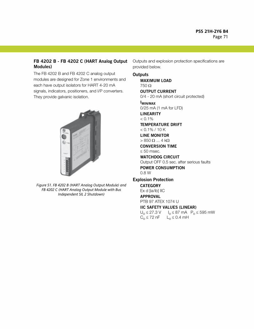
PSS 21H-2Y6 B4Page 71
FB 4202 B - FB 4202 C (HART Analog Output
Modules)
The FB 4202 B and FB 4202 C analog output modules are designed for Zone 1 environments and each have output isolators for HART 4-20 mA signals, indicators, positioners, and I/P converters. They provide galvanic isolation.
Figure 51. FB 4202 B (HART Analog Output Module) andFB 4202 C (HART Analog Output Module with Bus
Independent SIL 2 Shutdown)
Outputs and explosion protection specifications are provided below.
Outputs
MAXIMUM LOAD
750 ΩOUTPUT CURRENT
0/4 - 20 mA (short circuit protected)IMIN/MAX
0/25 mA (1 mA for LFD)LINEARITY
< 0.1%TEMPERATURE DRIFT
< 0.1% / 10 KLINE MONITOR
> 850 Ω ... 4 kΩCONVERSION TIME
≤ 50 msec.WATCHDOG CIRCUIT
Output OFF 0.5 sec. after serious faultsPOWER CONSUMPTION
0.8 W
Explosion Protection
CATEGORY
Ex d [ia/ib] IICAPPROVAL
PTB 97 ATEX 1074 UIIC SAFETY VALUES (LINEAR)
Uo ≤ 27.3 V Io ≤ 87 mA Po ≤ 595 mWCo ≤ 72 nF Lo ≤ 0.4 mH

PSS 21H-2Y6 B4Page 72
FB 4204 B - FB 4205 D (HART Analog Output
Modules, 4-Channels)
The FB 4204 B analog output module and the FB 4205 C and FB 4205 D HART analog output modules are designed for Zone 1 environments and have an output isolator for HART indicators, displays, and IP converters. They provide galvanic isolation between their input and the fieldbus (group isolation) and an optional bus independent shutdown input. Some versions support line monitoring (LFD).
Figure 52. FB 4204 B (Analog Output Modules, 4-Channels),FB 4205 C (HART Analog Output Modules, 4-Channels with
Bus Independent Shutdown) andFB 4205 D (HART Analog Output Modules, 4-Channels with
LFD)
Inputs and explosion protection specifications are provided below.
Inputs
MAXIMUM LOAD
750 ΩOUTPUT CURRENT
4 - 20 mA (0 - 25 mA) short protectedLINEARITY
0.1%TEMPERATURE DRIFT
0.1% / 10 KLINE MONITOR
Min. 0.5 mATHRESHOLD
> 850 ΩWATCHDOG CIRCUIT
Output OFF 0.5 sec. after serious faultsSCANNING TIME
6.5 msMEMORY UPDATE TIME
58 ms (4-channels)110 ms (during HART communications)POWER CONSUMPTION
3 W
Explosion Protection
CATEGORY
II 2 (1/2) G Ex d [ia/ib] IICAPPROVAL
PTB 97 ATEX 1074 UIIC SAFETY VALUES (LINEAR)
Uo ≤ 27.3 V Io ≤ 93 mA Po ≤ 635 mWCo ≤ 74 nF Lo ≤ 0.4 mH

PSS 21H-2Y6 B4Page 73
FB 4302 C and FB 4302 C200 (HART Analog
Output Modules)
The FB 4302 C and FB 4302 C200 HART analog output modules are designed for Zone 1 environments and have an output isolator for HART 4-20 mA signals, indicators, positioners, and I/P converters. They provide galvanic isolation, Ex-e terminals accessible when volt-free and an optional bus independent shutdown feature.
Figure 53. FB 4302 C (HART Analog Output Modules)
Outputs and explosion protection specifications are provided below.
Outputs
MAXIMUM LOAD
750 ΩOUTPUT CURRENT
0/4 - 20 mA (short circuit protected)IMIN/MAX
0/25 mA (1 mA for LFD)LINEARITY
< 0.1%TEMPERATURE DRIFT
< 0.1% / 10 KLINE MONITOR
> 850 Ω ... 4 kΩWATCHDOG CIRCUIT
Output OFF 0.5 sec. after serious faultsCONNECTION
FB 4302 CPlug-in Ex-e front connectors with IP30 hood; field wiring goes directly to the connector; connector and hood supplied with I/O module (recommended for new installations)
NOTEA hot work permit is required for access to the connector under the hood.
FB 4302 C2002 m cable tails to Ex-e terminals
CONVERSION TIME
≤ 50 msec.POWER CONSUMPTION
1 W
Explosion Protection
CATEGORY
II 2 G Ex d IICAPPROVAL
PTB 97 ATEX 1074 U

PSS 21H-2Y6 B4Page 74
FB 4305 B and FB 4305 B200 (HART Analog
Output Module, 4-Channels)
The FB 4305 B and FB 4305 B200 HART analog output modules are designed for Zone 1 environments and has an output isolator for proportional valves, displays or IP converters. They provide galvanic isolation between their inputs and the fieldbus. They can be unplugged when their Ex-e circuits are volt-free.
Figure 54. FB 4305 B (HART Analog Output Module,4-Channels)
Inputs and explosion protection specifications are provided below.
Inputs
MAXIMUM LOAD
750 Ω (at 22 mA)OUTPUT RANGE
4 - 20 mA (0 - 25 mA) short protectedCURRENT LIMIT
Approximately 25 mALINEARITY
0.1%TEMPERATURE DRIFT
0.1% / 10 KLINE MONITOR (LFD)
Min. 0.5 mAWATCHDOG CIRCUIT
Output OFF 0.5 sec. after serious faultsMEMORY UPDATE TIME
58 ms (4-channels)110 ms (during HART communications)CONNECTION
FB 4305 BPlug-in Ex-e front connectors with IP30 hood; field wiring goes directly to the connector; connector and hood supplied with I/O module (recommended for new installations)
NOTEA hot work permit is required for access to the connector under the hood.
FB 4305 B2002 m cable tails to Ex-e terminals
POWER CONSUMPTION
3 W
Explosion Protection
CATEGORY
II 2 G Ex d IICAPPROVAL
PTB 97 ATEX 1074 U
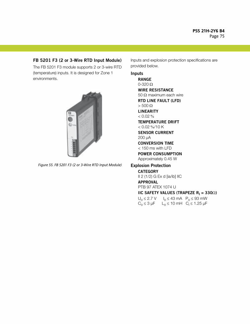
PSS 21H-2Y6 B4Page 75
FB 5201 F3 (2 or 3-Wire RTD Input Module)
The FB 5201 F3 module supports 2 or 3-wire RTD (temperature) inputs. It is designed for Zone 1 environments.
Figure 55. FB 5201 F3 (2 or 3-Wire RTD Input Module)
Inputs and explosion protection specifications are provided below.
Inputs
RANGE
0-320 ΩWIRE RESISTANCE
50 Ω maximum each wireRTD LINE FAULT (LFD)
> 500 ΩLINEARITY
< 0.02 %TEMPERATURE DRIFT
< 0.02 %/10 KSENSOR CURRENT
200 µACONVERSION TIME
< 150 ms with LFDPOWER CONSUMPTION
Approximately 0.45 W
Explosion Protection
CATEGORY
II 2 (1/2) G Ex d [ia/ib] IICAPPROVAL
PTB 97 ATEX 1074 UIIC SAFETY VALUES (TRAPEZE RI = 330Ω)
Uo ≤ 2.7 V Io ≤ 43 mA Po ≤ 93 mWCo ≤ 3 µF Lo ≤ 10 mH Ci ≤ 1.25 µF
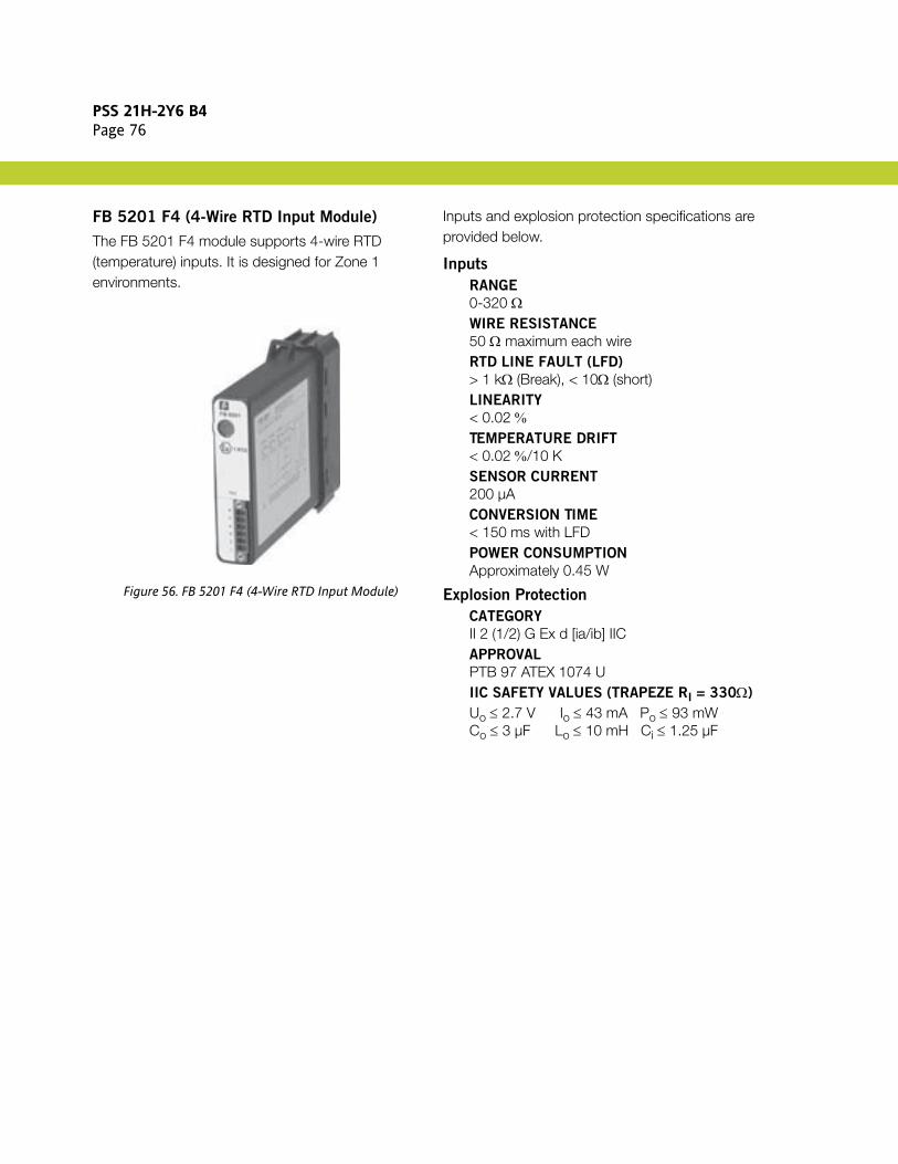
PSS 21H-2Y6 B4Page 76
FB 5201 F4 (4-Wire RTD Input Module)
The FB 5201 F4 module supports 4-wire RTD (temperature) inputs. It is designed for Zone 1 environments.
Figure 56. FB 5201 F4 (4-Wire RTD Input Module)
Inputs and explosion protection specifications are provided below.
Inputs
RANGE
0-320 ΩWIRE RESISTANCE
50 Ω maximum each wireRTD LINE FAULT (LFD)
> 1 kΩ (Break), < 10Ω (short)LINEARITY
< 0.02 %TEMPERATURE DRIFT
< 0.02 %/10 KSENSOR CURRENT
200 µACONVERSION TIME
< 150 ms with LFDPOWER CONSUMPTION
Approximately 0.45 W
Explosion Protection
CATEGORY
II 2 (1/2) G Ex d [ia/ib] IICAPPROVAL
PTB 97 ATEX 1074 UIIC SAFETY VALUES (TRAPEZE RI = 330Ω)
Uo ≤ 2.7 V Io ≤ 43 mA Po ≤ 93 mWCo ≤ 3 µF Lo ≤ 10 mH Ci ≤ 1.25 µF

PSS 21H-2Y6 B4Page 77
FB 5202 F (Thermocouple Input Module)
The FB 5202 F module supports thermocouple or mV inputs with cold junction compensation. It is designed for Zone 1 environments.
Figure 57. FB 5202 F (Thermocouple Input Module)
Inputs and explosion protection specifications are provided below.
Inputs
RANGE
e.g. Type U, B, E, T, K, S, R, L, J, N, PallaplatMEASURING RANGE
-10.5 mV .... + 69.5 mVCOMPENSATION
Internal (at connector) or externalCJC PT100 SENSOR CURRENT
200 µACONVERSION TIME FOR EXTERNAL CJC
< 80 ms with LFDCONVERSION TIME FOR INTERNAL CJC
< 250 ms with LFDLINEARITY
< 0.007 %TEMPERATURE DRIFT
< 0.02 %/10 KLINE FAULT (LFD)
> 1 kΩPOWER CONSUMPTION
Approximately 0.45 W
Explosion Protection
CATEGORY
II 2 (1/2) G Ex d [ia/ib] IICAPPROVAL
PTB 97 ATEX 1074 UIIC SAFETY VALUES (TRAPEZE RI = 330Ω)
Uo ≤ 1.8 V Io ≤ 43 mA Po ≤ 67 mWCo ≤ 8.7 µF Lo ≤ 10 mH Ci ≤ 100 nF

PSS 21H-2Y6 B4Page 78
FB 5204 F3 (2 or 3-Wire RTD Input Module,
4-Channels)
The FB 5204 F3 module supports 2 or 3-wire RTD or slide wire sensor inputs. It is designed for Zone 1 environments and it has group isolation.
Figure 58. FB 5204 F3 (2 or 3-Wire RTD Input Module,4-Channels)
Inputs and explosion protection specifications are provided below.
Inputs
RTD RANGE
0-320 ΩSLIDE WIRE SENSORS
0-320 ΩSENSOR CURRENT
< 0.22 mAWIRE RESISTANCE
< 50 Ω each wireLINE BREAK DETECTION
> 1 kΩ (Break)NONLINEARITY
0.02%TEMPERATURE DRIFT
0.02%/10 KSCAN TIME
6.5 msCONVERSION TIME
< 1000 ms (4 channels)CONNECTION
Screw plug-in or wire clamp connectorsPOWER CONSUMPTION
Approximately 0.6W
Explosion Protection
CATEGORY
II 2 (1/2) G Ex d [ia/ib] IICAPPROVAL
PTB 97 ATEX 1074 UIIC SAFETY VALUES (TRAPEZE RI = 103Ω)
Uo ≤ 6.8 V Io ≤ 70 mA Po ≤ 118 mWCo ≤ 1 µF Lo ≤ 5 mH Ci ≤ 100 nF
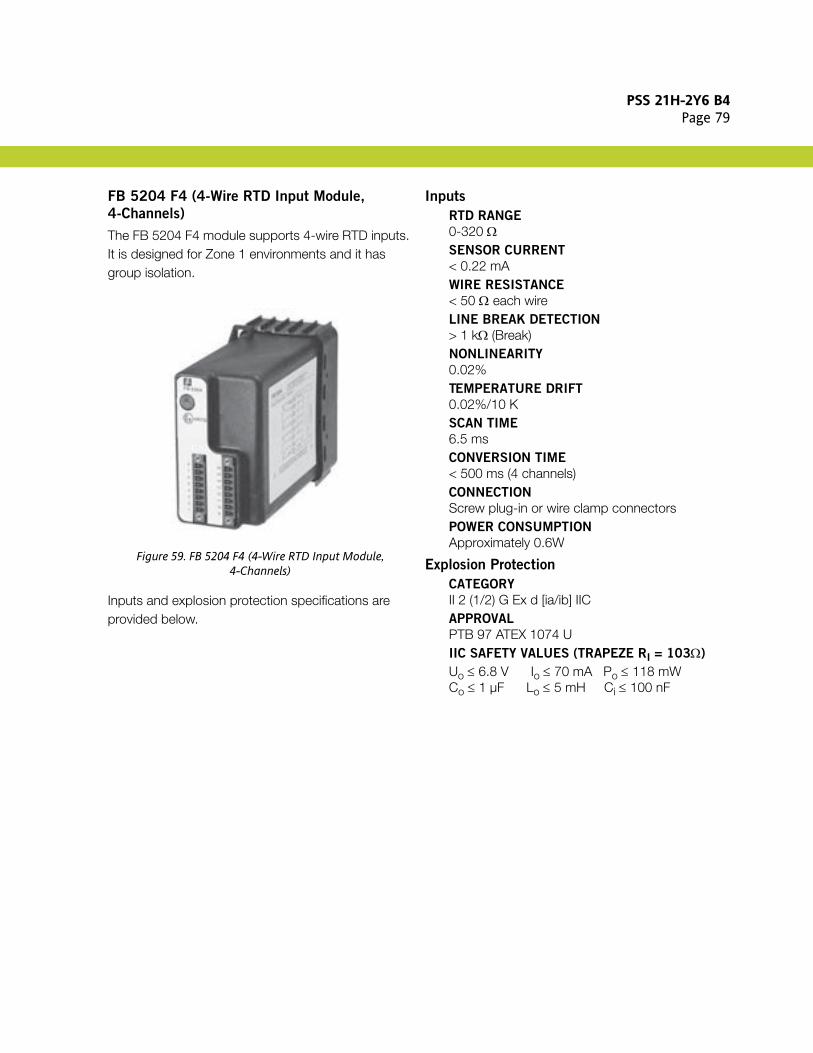
PSS 21H-2Y6 B4Page 79
FB 5204 F4 (4-Wire RTD Input Module,
4-Channels)
The FB 5204 F4 module supports 4-wire RTD inputs. It is designed for Zone 1 environments and it has group isolation.
Figure 59. FB 5204 F4 (4-Wire RTD Input Module,4-Channels)
Inputs and explosion protection specifications are provided below.
Inputs
RTD RANGE
0-320 ΩSENSOR CURRENT
< 0.22 mAWIRE RESISTANCE
< 50 Ω each wireLINE BREAK DETECTION
> 1 kΩ (Break)NONLINEARITY
0.02%TEMPERATURE DRIFT
0.02%/10 KSCAN TIME
6.5 msCONVERSION TIME
< 500 ms (4 channels)CONNECTION
Screw plug-in or wire clamp connectorsPOWER CONSUMPTION
Approximately 0.6W
Explosion Protection
CATEGORY
II 2 (1/2) G Ex d [ia/ib] IICAPPROVAL
PTB 97 ATEX 1074 UIIC SAFETY VALUES (TRAPEZE RI = 103Ω)
Uo ≤ 6.8 V Io ≤ 70 mA Po ≤ 118 mWCo ≤ 1 µF Lo ≤ 5 mH Ci ≤ 100 nF

PSS 21H-2Y6 B4Page 80
FB 5205 F (Thermocouple Input Module,
4-Channels)
The FB 5205 F module supports thermocouple or mV inputs with cold junction compensation. It is designed for Zone 1 environments and it has galvanic isolation between channels.
Figure 60. FB 5205 F (Thermocouple Input Module,4-Channels)
Inputs and explosion protection specifications are provided below.
Inputs
RANGE
e.g. Type U, B, E, T, K, S, R, L, J, N, PallaplatMEASURING RANGE
-10.5 mV .... + 69.5 mVCOMPENSATION
Internal (built-in) CJC onlyLINE FAULT DETECTION (LFD)
> 1 kΩNONLINEARITY
< 0.007 %TEMPERATURE DRIFT
< 0.02 %/10 KCYCLE TIME (COM UNIT)
6.5 msCONVERSION TIME
< 600 ms (4 channels) with LFDCONNECTION
Screw plug-in or wire clamp connectorsTEST VOLTAGE
0.5 kV input - input1.5 kV input - bus and powerPOWER CONSUMPTION
Approximately 1 W
Explosion Protection
CATEGORY
II 2 (1/2) G Ex d [ia/ib] IICAPPROVAL
PTB 97 ATEX 1074 UIIC SAFETY VALUES (TRAPEZE RI = 500Ω)
Uo ≤ 1 V Io ≤ 71 mA Po ≤ 62 mWCo ≤ 33 µF Lo ≤ 5 mH Ci ≤ 100 nF

PSS 21H-2Y6 B4Page 81
FB 5206 B (Voltage Converter Module)
The FB 5206 B voltage converter module supports inputs for 0-10V input signals. It is designed for Zone 1 environments and it provides galvanic isolation between its input and the fieldbus.
Figure 61. FB 5206 B (Voltage Converter Module)
Inputs and explosion protection specifications are provided below.
Inputs
RANGE
0 - +10 VSMALLEST SPAN FOR 0,1%
500 mVINPUT IMPEDANCE
100 kΩLINE FAULT DETECTION (LFD)
NoneLINEARITY
< 0,1% TypicalTEMPERATURE DRIFT
< 0.1% / 10 KCONVERSION TIME
100 msPOWER CONSUMPTION
< 0.45 W
Explosion Protection
CATEGORY
II 2 1) G Ex d [ia/ib] IICAPPROVAL
PTB 97 ATEX 1074 UIIC SAFETY VALUES (LINEAR)
Uo ≤ 0.9 V Io ≤ 0.2 mA Po ≤ 0.2 mWCo ≤ 53 µF Lo ≤ 100 mH Ci ≤ 52 nF

PSS 21H-2Y6 B4Page 82
FB 6208 B (Digital Output Module,
8-Channels, Low Power)
The FB 6208 B digital output module is designed for Zone 1 environments and supports active 20 V outputs to switch LEDs, indicators, or low power solenoid valves. It provides galvanic isolation between its outputs and the fieldbus (group isolation).
Figure 62. FB 6208 B (Digital Output Module, 8-Channels, Low Power with Bus Independent Shutdown)
Outputs and explosion protection specifications are provided below.
Outputs
DIGITAL OUTPUT (ACTIVE/SHORT
PROTECTED)
20 V, 8 mA per channelSCANNING TIME
6.5 msLFD TEST CURRENT
0.33 mAWATCHDOG CIRCUIT
Output volt-free 0.5 sec. after serious faultsPOWER CONSUMPTION
2.2 W
Explosion Protection
CATEGORY
II 2 (2) G Ex d [ib] IICAPPROVAL
PTB 97 ATEX 1074 UIIC SAFETY VALUES (RECTANGULAR) MODEL
A6108
Uo ≤ 28 V Io ≤ 13.5 mA Po ≤ 376 mWCo ≤ 76 nF Lo ≤ 0.5 mHIIC SAFETY VALUES (RECTANGULAR) MODEL
C6108
Uo ≤ 30 V Io ≤ 13.5 mA Po ≤ 404 mWCo ≤ 62 nF Lo ≤ 0.5 mH

PSS 21H-2Y6 B4Page 83
FB 6210 B - FB 6215 ES (Digital Output
Module, 4-Channels, Intrinsically Safe Power)
The FB 6210 B to FB 6215 ES digital output modules are designed for Zone 1 environments and support outputs for intrinsically safe solenoid valves, and for sounders and LEDs. They provide galvanic isolation between their outputs and the fieldbus (group isolation).
Figure 63. FB 6210 B - FB 6215 ES (Digital Output Module, 4-Channels, Intrinsically Safe Power)
Power supply, outputs and explosion protection specifications are provided below.
Power Supply
EXTERNAL POWER
24 V dc, 5 W via Booster Ex-e module front end connection.
Outputs
DRIVE CAPABILITY
See Table 16 and Table 17 below.LINE MONITOR (2MS TEST PULSE)
Every 2.5 secLFD REACTION TIME
10 s (worst case)OUTPUT RESPONSE TIME
> 10 ms (depending on the master)SCAN RATE
6.5 msWATCHDOG CIRCUIT
Output OFF 0.5 sec. after serious faultsCONNECTION
Screw plug-in or wire clamp connectors for intrinsically safe circuits, and wire ends for Booster Ex-ePOWER CONSUMPTION
0.6 W
Explosion Protection
CATEGORY
II 2 (2/1) G Ex de [ia/ib] IICAPPROVAL
PTB 97 ATEX 1074USAFETY VALUES
See Table 16 and Table 17 below.
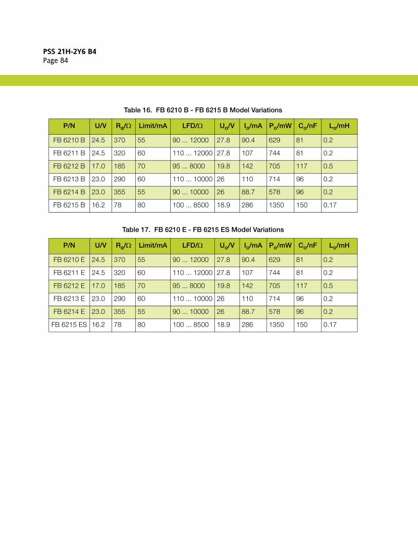
PSS 21H-2Y6 B4Page 84
Table 16. FB 6210 B - FB 6215 B Model Variations
P/N U/V Ra/Ω Limit/mA LFD/Ω Uo/V Io/mA Po/mW Co/nF Lo/mH
FB 6210 B 24.5 370 55 90 ... 12000 27.8 90.4 629 81 0.2
FB 6211 B 24.5 320 60 110 ... 12000 27.8 107 744 81 0.2
FB 6212 B 17.0 185 70 95 ... 8000 19.8 142 705 117 0.5
FB 6213 B 23.0 290 60 110 ... 10000 26 110 714 96 0.2
FB 6214 B 23.0 355 55 90 ... 10000 26 88.7 578 96 0.2
FB 6215 B 16.2 78 80 100 ... 8500 18.9 286 1350 150 0.17
Table 17. FB 6210 E - FB 6215 ES Model Variations
P/N U/V Ra/Ω Limit/mA LFD/Ω Uo/V Io/mA Po/mW Co/nF Lo/mH
FB 6210 E 24.5 370 55 90 ... 12000 27.8 90.4 629 81 0.2
FB 6211 E 24.5 320 60 110 ... 12000 27.8 107 744 81 0.2
FB 6212 E 17.0 185 70 95 ... 8000 19.8 142 705 117 0.5
FB 6213 E 23.0 290 60 110 ... 10000 26 110 714 96 0.2
FB 6214 E 23.0 355 55 90 ... 10000 26 88.7 578 96 0.2
FB 6215 ES 16.2 78 80 100 ... 8500 18.9 286 1350 150 0.17

PSS 21H-2Y6 B4Page 85
FB 6301 H200 (Digital Relay Output Module,
2-Channels, Ex-e)
The FB 6301 H200 digital relay output module is designed for Zone 1 environments and supports switches with 24 V or 230 V power circuits and Ex-d solenoid valves. It provides galvanic isolation between its outputs and the fieldbus, as well as other outputs, and provides access to Ex-e connections when volt-free.
Figure 64. FB 6301 H200 (Digital Relay Output Module,2-Channels, Ex-e)
Outputs and explosion protection specifications are provided below.
Outputs
VOLTAGE RATING (NOMINAL)
24 V dc, 24 V ac (30 V max.) / 230 V acCURRENT RATING
1 A, ac/dc (resistive load)SWITCH POWER
30 vA, 30 W, 230 vAELECTRICAL LIFETIME
0.5 Mio. cyclesMIN. SWITCHING CAPABILITY
> 1 V, > 1 mACONTACT MATERIAL
AgPd gold platedWATCHDOG CIRCUIT
Output OFF 0.5 sec. after serious faultsRESPONSE TIME
Approximately < 20 ms (depending on bus cycle time)SCANNING TIME
Approximately < 6.5 msCONNECTION
2 m cable tails to Ex-e terminalsPOWER CONSUMPTION
0.65 W
Explosion Protection
CATEGORY
II 2 G Ex d IICAPPROVAL
PTB 97 ATEX 1074 U
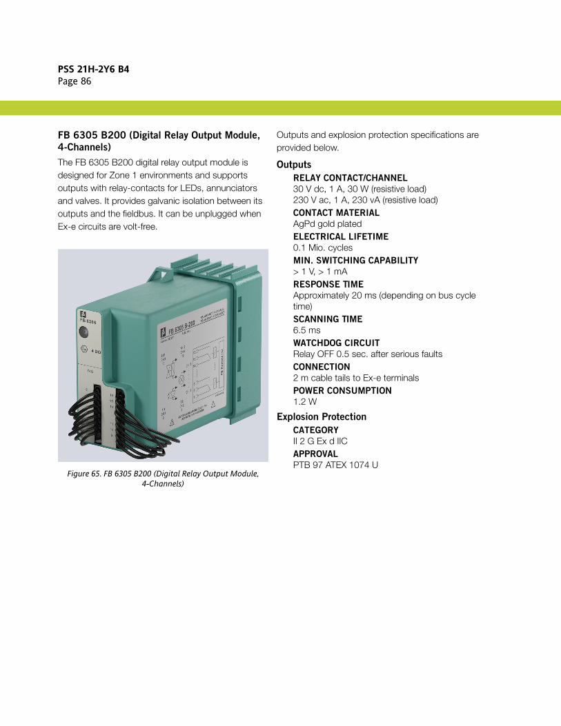
PSS 21H-2Y6 B4Page 86
FB 6305 B200 (Digital Relay Output Module,
4-Channels)
The FB 6305 B200 digital relay output module is designed for Zone 1 environments and supports outputs with relay-contacts for LEDs, annunciators and valves. It provides galvanic isolation between its outputs and the fieldbus. It can be unplugged when Ex-e circuits are volt-free.
Figure 65. FB 6305 B200 (Digital Relay Output Module,4-Channels)
Outputs and explosion protection specifications are provided below.
Outputs
RELAY CONTACT/CHANNEL
30 V dc, 1 A, 30 W (resistive load)230 V ac, 1 A, 230 vA (resistive load)CONTACT MATERIAL
AgPd gold platedELECTRICAL LIFETIME
0.1 Mio. cyclesMIN. SWITCHING CAPABILITY
> 1 V, > 1 mARESPONSE TIME
Approximately 20 ms (depending on bus cycle time)SCANNING TIME
6.5 msWATCHDOG CIRCUIT
Relay OFF 0.5 sec. after serious faultsCONNECTION
2 m cable tails to Ex-e terminalsPOWER CONSUMPTION
1.2 W
Explosion Protection
CATEGORY
II 2 G Ex d IICAPPROVAL
PTB 97 ATEX 1074 U

PSS 21H-2Y6 B4Page 87
FB 6306 B and FB 6306 B200 (Digital Relay
Output Module, 8-Channels)
The FB 6306 B and FB 6306 B200 digital relay output modules are designed for Zone 1 environments and support outputs with relay-contacts for LEDs, annunciators or valves. They provide galvanic isolation between their outputs and the fieldbus. They can be unplugged when Ex-e circuits are volt-free.
Figure 66. FB 6306 B (Digital Relay Output Module,8-Channels)
Outputs and explosion protection specifications are provided below.
Outputs
RELAY CONTACT/CHANNEL
24 V ac/dc, 1 A, 30 W, 30 vA (resistive load)CONTACT MATERIAL
AgPd gold platedELECTRICAL LIFETIME
0.5 Mio. cyclesMIN. SWITCHING CAPABILITY
> 1 V, > 1 mARESPONSE TIME
Approximately 20 ms (depending on bus cycle time)SCANNING TIME
6.5 msWATCHDOG CIRCUIT
Relay OFF 0.5 sec. after serious faultsCONNECTION
FB 6306 BPlug-in Ex-e front connectors with IP30 hood; field wiring goes directly to the connector; connector and hood supplied with I/O module (recommended for new installations)
NOTEA hot work permit is required for access to the connector under the hood.
FB 6306 B2002 m cable tails to Ex-e terminals
POWER CONSUMPTION
1.6 W
Explosion Protection
CATEGORY
II 2 G Ex d IICAPPROVAL
PTB 97 ATEX 1074 U

PSS 21H-2Y6 B4Page 88
FB 6308 B and FB 6308 B200 (Digital Output
Module, 8-Channels, Low Power)
The FB 6308 B and FB 6308 B200 digital output modules are designed for Zone 1 environments and support active outputs for low power loads, such as inputs of control stations. They provide galvanic isolation between their outputs and the fieldbus (group isolation) and a shutdown input. They can be unplugged when their Ex-e circuits are volt-free.
Figure 67. FB 6308 B (Digital Output Module, 8-Channels, Low Power)
Outputs and explosion protection specifications are provided below.
Outputs
DIGITAL OUTPUT (ACTIVE/SHORT
PROTECTED)
20 V, 8 mA per channelSCANNING TIME
6.5 msLFD TEST CURRENT
0.33 mAWATCHDOG CIRCUIT
Output volt-free 0.5 sec. after serious faultsCONNECTION
FB 6308 BPlug-in Ex-e front connectors with IP30 hood; field wiring goes directly to the connector; connector and hood supplied with I/O module (recommended for new installations)
NOTEA hot work permit is required for access to the connector under the hood.
FB 6308 B2002 m cable tails to Ex-e terminals
POWER CONSUMPTION
2.2 W
Explosion Protection
CATEGORY
II 2 G Ex d IICAPPROVAL
PTB 97 ATEX 1074 U

PSS 21H-2Y6 B4Page 89
FB 9293 F (HDLC Bus Termination Module)
The FB 9293 F module terminates the Intrinsically Safe I/O Subsystem’s fieldbus, and must be installed in the unit at the end of the fieldbus. It is designed for Zone 1 environments.
Figure 68. FB 9293 F (HDLC Bus Termination Module)
Inputs and explosion protection specifications are provided below.
Technical Data
BUS TERMINATION
Absolutely necessary for each last stationof a busline for field enclosures and cabinets
Explosion Protection
CATEGORY
II 2 G Ex d IICAPPROVAL
PTB 97 ATEX 1074 U

PSS 21H-2Y6 B4Page 90
FUNCTIONAL SPECIFICATIONS
Process I/O Communications
MODULE FIELDBUS COMMUNICATIONS
ISCM Transmission Rate2 Mbps
Process I/O Capacity
2 Mbps FIELDBUS
Cable LengthZone 2 Applications Between FCP270/FCM100E/Et and Intrinsically Safe I/O Subsystem60 m (197 ft) maximum, standard fieldbus cable Zone 1 Applications Between FCP270/FCM100E/Et and Intrinsically Safe I/O Subsystem152 m (500 ft) maximum, high quality twinaxial cable
P+F I/O ModulesUp to 46 (for Zone 2 applications) or 48 (for Zone 1 applications) supported P+F intrinsically safe I/O modules per ISCMISCMsRefer to “IS/IO SYSTEM CONFIGURATION REQUIREMENTS” on page 4.
NOTEWhen using the ISCM together with 200 Series FBMs under the same FCP270, the FEM100 module must be used to separate the fieldbus for the 200 Series FBMs from the FCP fieldbus. 100 Series FBMs are supported on an FCP270 as long as the FBI100 (Fieldbus Isolator) is used to separate the 100 Series FBMs modules from the FCP fieldbus. When using a ZCP270 with the ISCM, each ISCM must have a dedicated FCM100E/Et pair. 200 Series FBMs may also be supported on another FCM100E/Et pair. 100 Series FBMs may also be supported on yet another FCM100E pair.
NOTE100 Series FBMs are only supported by the FCM100E.
ISCM Letterbug AssignmentISCM letterbug is set through a letterbug module with rotary switch which is plugged into the ISCM.
Power Requirements
ISCM
2 WP+F I/O MODULES
Refer to “INVENSYS/P+F INTRINSICALLY SAFE MODULES SPECIFICATIONS” on page 28.
Input Specifications(3)
ZONE 1 POWER SUPPLIES FB 9215 B
(230 V AC) AND FB 9216 B (115 V AC)
50 to 60 Hz nominalZONE 1 POWER SUPPLY FB 9206 D (24 V DC)
20 to 30 V dc, 24 V dc nominalZONE 2 POWER SUPPLY LB 9006 C (24 V DC)
18 to 30 V dc, 24 V dc nominal
Regulatory Compliance
ISCM - EXPLOSION PROTECTION
ISCM for Zone 2 (LB-Style) Applications (P0924GT)See “Explosion Protection” on page 25.ISCM for Zone 1 (FB-Style) Applications (P0924GU)See “Explosion Protection” on page 26.
P+F I/O MODULES
Refer to “INVENSYS/P+F INTRINSICALLY SAFE MODULES SPECIFICATIONS” on page 28.
(3) For full specifications on all P+F power supplies, see P+F data sheets listed in “FOR MORE INFORMATION” on page 93.

PSS 21H-2Y6 B4Page 91
ENVIRONMENTAL SPECIFICATIONS(4)
Operating
ZONE 2 (LB-STYLE) APPLICATIONS
Category 3 equipment to EC regulations 94/9EC, mounted in Zone 2 or Zone 22 applications
Temperature-20 to +70°C (-4 to +158°F)(in intrinsically safe applications, for explosion protection, 60°C (140°F) maximum)Relative Humidity5 to 95% (noncondensing), <75% annual averageAltitude-300 to +3,000 m (-1,000 to +10,000 ft)Degree of Protection RequiredIP 54 in Zone 2 environmentsIP 6* for flammable dust environments
ZONE 1 (FB-STYLE) APPLICATIONS
Category 2 equipment to EC regulations 94/9EC, mounted in Zone 1 or 21 applications
Temperature (Outside Enclosure)(T6) -20 to +40°C (-4 to +104°F)(T4) -20 to +55°C (-4 to +131°F)Relative Humidity5 to 95% (noncondensing), <75% annual averageAltitude-300 to +3,000 m (-1,000 to +10,000 ft)Degree of Protection RequiredIP 54 in Zone 1 environmentsIP 6* for flammable dust environments
Storage
TEMPERATURE
-20 to +80°C (-4 to +176°F)RELATIVE HUMIDITY
5 to 95% (noncondensing), <75% annual averageALTITUDE
-300 to +12,000 m (-1,000 to +40,000 ft)
Contamination
POLLUTION TEST FOR PLUGS
acc IEC 68-2-4221 days with 25ppm SO2 at +25°C (+77°F) and 75% relative humidityENVIRONMENTAL TEST
Nb acc DIN IEC 68 part 2-14Cb acc DIN IEC 68 part 2-56G3 MIXED GAS CORROSION TEST
To ISA-S71.04.1985 G3 Harsh Group A (Zone 2 LB-Style)
(4) The environmental limits of the ISCM may be enhanced by the type of enclosure containing the module. Refer to the FB Remote I/O Bus System Hardware or LB Remote I/O Bus System Hardware documents (listed in “FOR MORE INFORMATION” on page 93) which describes the specific type of enclosure that is to be used.Be aware that Zone 1 power and bus cables must conform to increased safety requirements. Also consider the voltage drop which may occur across long power cables. Ensure that the remaining voltage does not drop below the minimum required for the power supply.

PSS 21H-2Y6 B4Page 92
PHYSICAL SPECIFICATIONS
MountingThe redundant installation consists of two ISCMs. A single ISCM can also be used.ISCM mounts on an intrinsically safe I/O base or extension unit and/or P+F enclosure (part numbers listed in “PEPPERL+FUCHS MODULAR REMOTE I/O SYSTEMS” on page 4). Refer to the FB Remote I/O Bus System Hardware or LB Remote I/O Bus System Hardware documents (listed in “FOR MORE INFORMATION” on page 93) for details.
ISCM Part Numbers
FOR ZONE 2 (LB-STYLE) APPLICATIONS
P0924GT (P+F P/N ISCM8100) - see page 25FOR ZONE 1 (FB-STYLE) APPLICATIONS
P0924GU (P+F P/N ISCM8200) - see page 26
Accessory Part Numbers
LETTERBUG ROTARY SWITCH MODULE
(PLUGS INTO P0924GT/P0924GU)
P0924GV (P+F P/N LTBM8001) - see page 27
Mass
ISCM (P0924GT) FOR ZONE 2 (LB-STYLE)
APPLICATIONS
0.1 kg (0.2 lb)ISCM (P0924GU) FOR ZONE 1 (FB-STYLE)
APPLICATIONS
1.0 kg (2.2 lb)
Dimensions
FOR ZONE 2 (LB-STYLE) APPLICATIONS
Double-Width ModulesHeight96 mm (3.78 in)Width32 mm (1.26 in)Depth100 mm (3.91 in)
Single-Width ModulesHeight96 mm (3.78 in)Width16 mm (0.63 in)Depth100 mm (3.91 in)
FOR ZONE 1 (FB-STYLE) APPLICATIONS
Double-Width ModulesHeight107 mm (4.21 in)Width57 mm (2.24 in)Depth132 mm (5.20 in)
Single-Width ModulesHeight107 mm (4.21 in)Width29 mm (1.14 in)Depth132 mm (5.20 in)

PSS 21H-2Y6 B4Page 93
FOR MORE INFORMATION
For more information, refer to the following Product Specification Sheets (PSS) and documentation:
Document Number Title
PSS 21H-1B9 B3 Field Control Processor (FCP270)
PSS 21H-1B10 B3 Z-Module Control Processor 270 (ZCP270)
PSS 21H-2W1 B3 DIN Rail Mounted Subsystem Overview
PSS 21H-2Y10 B4 FCM100Et Redundant Fieldbus Communications Module
PSS 21H-2Y11 B4 FCM100E Redundant Fieldbus Communications Module
PSS 21H-2Y16 B4 FEM100 Fieldbus Expansion Module
(Not Invensys-supplied)
FB Remote I/O Bus System Hardware (Revision B and earlier revisions of this document are titled “Operating Instructions for FB Remote I/O Housings Model FB92xx, FB9224, FB 9225, FB9248, FB9249 Base Unit, Extension Unit, Redundancy Unit”) - available at Pepperl+Fuchs website: www.pepperl-fuchs.com
(Not Invensys-supplied)
LB Remote I/O Bus System Hardware - available at Pepperl+Fuchs website: www.pepperl-fuchs.com
(Not Invensys-supplied)
LB 9006 24 V DC Power Supply Data Sheet - available at Pepperl+Fuchs website: www.pepperl-fuchs.com
(Not Invensys-supplied)
FB 9206 24 V DC Power Supply Data Sheet - available at Pepperl+Fuchs website: www.pepperl-fuchs.com
(Not Invensys-supplied)
FB 9204 - FB 9216 Power Supply Data Sheet - available at Pepperl+Fuchs website: www.pepperl-fuchs.com

PSS 21H-2Y6 B4Page 94

PSS 21H-2Y6 B4Page 95

PSS 21H-2Y6 B4Page 96
Invensys Operations Management5601 Granite Parkway Suite 1000Plano, TX 75024United States of Americahttp://iom.invensys.com
Global Customer SupportInside U.S.: 1-866-746-6477Outside U.S.: 1-508-549-2424 or contact your local Invensys representative.Email: [email protected]: http://support.ips.invensys.com
Invensys, Foxboro, I/A Series, InFusion, FoxView and the Invensys logo are trademarks of Invensys plc, its subsidiaries, and affiliates.All other brands and product names may be the trademarks of their respective owners.
Copyright 2009-2010 Invensys Systems, Inc. All rights reserved. Unauthorized duplication or distribution is strictly prohibited.
MB 21A 1110