iai 03 rc general_cj0203-2_a_p145-300_rod
TRANSCRIPT

RCP4 ROBO Cylinder RCP4 ROBO Cylinder
145 Rod Type
Rod Type
Rod Type
RCP4 RCP3RCP2
ERC3ERC2RCD
RCA2RCARCS2
RCP4 series
Standard Type Coupling Type 52mm Width RCP4-RA5C 14761mm Width RCP4-RA6C 149
Side-Mounted Motor Type 52mm Width RCP4-RA5R 15161mm Width RCP4-RA6R 153
RCP3 series
Mini Type Coupling Type 22mm Width RCP3-RA2AC 15528mm Width RCP3-RA2BC 157
Side-Mounted Motor Type 22mm Width RCP3-RA2AR 15928mm Width RCP3-RA2BR 161
RCP2 series
Standard Type Coupling Type 25mm Width RCP2-RA2C 16335mm Width RCP2-RA3C 165
High-Thrust Type Coupling Type 85mm Width RCP2-RA8C 167Side-Mounted Motor Type 85mm Width RCP2-RA8R 169Coupling Type 100mm Width RCP2-RA10C 171
Short-Length Type Standard Type 45mm Width RCP2-SRA4R 173Single-Guide Type 45mm Width RCP2-SRGS4R 175Double-Guide Type 45mm Width RCP2-SRGD4R 177
Controller-Integrated Type with Pulse Motor
ERC3 series
Controller-Integrated Type Standard Type 45mm Width ERC3-RA4C 17964mm Width ERC3-RA6C 181
ERC2 series
Controller-Integrated Type Standard Type 58mm Width ERC2-RA6C 18368mm Width ERC2-RA7C 185
Single-Guide Type 58mm Width ERC2-RGS6C 18768mm Width ERC2-RGS7C 189
Double-Guide Type 58mm Width ERC2-RGD6C 19168mm Width ERC2-RGD7C 193
DC Brushless Motor Type
RCD series
Mini Cylinder 12mm Width RCD-RA1D 195
Pulse Motor Type

RCP4 ROBO Cylinder RCP4 ROBO Cylinder
Rod Type 146
RCA2 series24VServoMotorType
Mini Rod Type Coupling Type 18mm Width RCA2-RA2AC 197Side-Mounted Motor Type 18mm Width RCA2-RA2AR 199Short-Length Type 28mm Width RCA2-RN3NA 201
34mm Width RCA2-RN4NA 20328mm Width RCA2-RP3NA 20534mm Width RCA2-RP4NA 207
Single-Guide Type 28mm Width RCA2-GS3NA 20934mm Width RCA2-GS4NA 211
Double-Guide Type 28mm Width RCA2-GD3NA 21334mm Width RCA2-GD4NA 215
Slide Unit Type 60mm Width RCA2-SD3NA 21772mm Width RCA2-SD4NA 219
RCA series24VServo MotorType
Standard Type Coupling Type ø32mm RCA-RA3C 221ø37mm RCA-RA4C 223
Build-in Type ø32mm RCA-RA3D 225ø37mm RCA-RA4D 227
Side-Mounted Motor Type ø32mm RCA-RA3R 229ø37mm RCA-RA4R 231
Short-Length Type 45mm Width RCA-SRA4R 233Single-Guide Type Coupling Type ø32mm RCA-RGS3C 235
ø37mm RCA-RGS4C 237Build-in Type ø32mm RCA-RGS3D 239
ø37mm RCA-RGS4D 241Short-Length Type 45mm Width RCA-SRGS4R 243
Double-Guide Type Coupling Type ø32mm RCA-RGD3C 245ø37mm RCA-RGD4C 247
Build-in Type ø32mm RCA-RGD3D 249ø37mm RCA-RGD4D 251
Side-Mounted Motor Type ø32mm RCA-RGD3R 253ø37mm RCA-RGD4R 255
Short-Length Type 45mm Width RCA-SRGD4R 257
RCS2 series200VServoMotorType
Mini Rod Type Short-Length Type 46mm Width RCS2-RN5N 25946mm Width RCS2-RP5N 26146mm Width RCS2-GS5N 26346mm Width RCS2-GD5N 26594mm Width RCS2-SD5N 267
Standard Type Coupling Type ø37mm RCS2-RA4C 26955mm Width RCS2-RA5C 271
Build-in Type ø37mm RCS2-RA4D 273Short-Length Type 75mm Width RCS2-SRA7BD 275Side-Mounted Motor Type ø37mm RCS2-RA4R 277
55mm Width RCS2-RA5R 279130mm Width RCS2-RA13R 281
Single-Guide Type Coupling Type ø37mm RCS2-RGS4C 28355mm Width RCS2-RGS5C 285
Build-in Type ø37mm RCS2-RGS4D 287Short-Length Type 75mm Width RCS2-SRGS7BD 289
Double-Guide Type Coupling Type ø37mm RCS2-RGD4C 29155mm Width RCS2-RGD5C 293
Build-in Type ø37mm RCS2-RGD4D 295Short-Length Type 75mm Width RCS2-SRGD7BD 297Side-Mounted Motor Type ø37mm RCS2-RGD4R 299
Mini
Mini
Mini
SliderType
RodType
Table/Arm/Flat Type
Linear ServoType
Gripper/Rotary Type
Clean-room Type
Splash-ProofType
Pulse Motor
Servo Motor (24V)
Servo Motor (200V)
LinearServo Motor
Standard
Standard
Standard
ControllersIntegrated
ControllersIntegrated
Rod Type

RCP4 ROBO Cylinder RCP4 ROBO Cylinder
147 RCP4-RA5C
Mini
Mini
Mini
SliderType
RodType
Table/Arm/
Flat Type
Linear ServoType
Gripper/Rotary
Type
Clean-room Type
Splash-ProofType
Pulse Motor
Servo Motor (24V)
Servo Motor (200V)
LinearServo Motor
Standard
Standard
Standard
ControllersIntegrated
ControllersIntegrated
Appendix
P.5
(1) The maximum payload is the value when operated at 0.3G (0.2G with some models) acceleration. The upper limit of acceleration is 1G (*). Note that raising the acceleration causes the payload to drop.
(*) The specific value varies depending on the connected controller and actuator lead. For details, refer to “Selection References” on page A-101 and A-103.
(2) Take note that the maximum payload and maximum speed vary depending on the controller connected to the RCP4. (Refer to the actuator specifications below.)
(3) All horizontal payloads are values when an external guide is used.(4) See page A-71 for details on push motion.
Built-in guide mechanism
Actuator Specifications
Model number Lead(mm)
Connected controller
Maximum payload Max. push force (N)
Stroke(mm)Horizontal (kg) Vertical (kg)
Standard specification
RCP4-RA5C-I-42P-20- ➀ -P3- ➁ - ➂ 20 PCON-CA 6 1.5 56
50 to 400
(every 50mm)
MSEP-C 6 1.5 (*)
RCP4-RA5C-I-42P-12- ➀ -P3- ➁ - ➂ 12 PCON-CA 25 4 93MSEP-C 25 (*) 4 (*)
RCP4-RA5C-I-42P-6- ➀ -P3- ➁ - ➂ 6 PCON-CA 40 10 185MSEP-C 40 (*) 10 (*)
RCP4-RA5C-I-42P-3- ➀ -P3- ➁ - ➂ 3 PCON-CA 60 20 370MSEP-C 40 (*) 10 (*)High-thrust specification RCP4-RA5C-I-42SP-3- ➀ -P3- ➁ - ➂ -B 3 PCON-CA — 35 750— — —
■ Leads and Payloads ■ Stroke and Maximum Speed
Code explanation ➀ Stroke ➁ Cable length ➂ Options *See page A-71 for details on push motion. (Unit: mm/s)
Lead(mm)
Stroke 50~400(every 50mm)Connected cotroller
20 PCON-CA 800MSEP-C 640
12 PCON-CA 700MSEP-C 500
6 PCON-CA 450MSEP-C 250
3(Standard)
PCON-CA 225MSEP-C 125
3(High-thrust) PCON-CA 80
(*) When operated at 0.2 G
Stroke (mm) Standard priceStandard High-thrust
50 — —100 — —150 — —200 — —250 — —300 — —350 — —400 — —
Stroke
Name Option code Page Standard PriceBrake B ➝ A-42 —Optional cable exit direction (top) CJT ➝ A-42 —Optional cable exit direction (right) CJR ➝ A-42 —Optional cable exit direction (left) CJL ➝ A-42 —Optional cable exit direction (bottom) CJB ➝ A-42 —Flange bracket FL ➝ A-44 —Non-motor end specification NM ➝ A-52 —Scraper SC ➝ A-55 —
➂Options
(*1) The value at lead 20 is shown in [ ].
Item DescriptionDrive method Ball screw, ø10mm, rolled C10Positioning repeatability (*1) ±0.02mm [±0.03mm]Lost motion 0.1mm or less Rod ø22mm stainless steel pipeRod non-rotation precision ±0 degAllowable rod load mass Refer to page 148 and page A-117Rod tip overhang distance 100mm or lessAmbient operating temperature/humidity 0 to 40°C, 85% RH max. (Non-condensing)
Actuator Specifications
RCP4-RA5C Horizontal, PCON-CA connected RCP4-RA5C Vertical, PCON-CA connected
RCP4-RA5C Horizontal, MSEP connected RCP4-RA5C Vertical, MSEP connected
This graph assumes that the actuator is operated at 0.3 G. This graph assumes that the
actuator is operated at 0.3 G.Horizontal
Horizontal
Vertical
Vertical
800 900500300 600 700400100 2000Speed (mm/s)
800 900500300 600 700400100 2000Speed (mm/s)
500300 600 700400100 2000Speed (mm/s)
500300 600 700400100 2000Speed (mm/s)
Payl
oad
(kg)
40
35
30
25
20
15
10
5
0
Lead 3 (High-thrust speci�cation)
Lead 3 (Standard speci�cation)
Lead 3
Lead 3
Lead 3
Lead 6
Lead 6
Lead 6
Lead 6
Lead 12
Lead 12
Lead 12
Lead 12
Lead 20
Lead 20
1221.5
4
41.5
4
3
Lead 20
Lead 20
66
25
816
3
70
60
50
40
30
20
10
0
Payl
oad
(kg)
Payl
oad
(kg)
25
20
15
10
5
01
0.5
This graph assumes that theactuator is operated at 0.2 G.
Payl
oad
(kg)
4540353025201510
50
6
The values for leads 3/6/12 are based on operation at 0.2G,
and lead 20 is 0.3G.
■ Correlation Diagrams of Speed and Payload * The values of the horizontal specification assume that an external guide is used.
Operated by the MSEP-C
Operated by the PCON-CA
RCP4-RA5CROBO Cylinder, Rod Type, Motor Unit Coupled, Actuator Width 52mm, 24-V Pulse Motor
RCS2Series Type Encoder type Cable lengthMotor type Lead Stroke OptionsApplicable controller
I P3
42P: Pulse motor, size 4242SP: High-thrust pulse motor size 42
I: Incremental P3: PCON-CA MSEP-C
N: None P: 1m S: 3m M: 5mX : Custom lengthR : Robot cable
See Options below.
* If the high-thrust pulse motor is selected, the actuator comes standard with option B (Brake).
50: 50mm
400: 400mm(50mm pitch increments)
20 : 20mm 12 : 12mm 6 : 6mm 3 : 3mm
* See page Pre-47 for details on the model descriptions.
RA5CModel SpecificationItems
RCP4
Cable LengthType Cable symbol Standard price
Standard typeP (1m) —S (3m) —M (5m) —
Special lengthX06 (6m) ~ X10 (10m) —X11 (11m) ~ X15 (15m) —X16 (16m) ~ X20 (20m) —
Robot cable
R01 (1m) ~ R03 (3m) —R04 (4m) ~ R05 (5m) —R06 (6m) ~ R10 (10m) —R11 (11m) ~ R15 (15m) —R16 (16m) ~ R20 (20m) —
* See page A-59 for cables for maintenance.

RCP4 ROBO Cylinder RCP4 ROBO Cylinder
RCP4-RA5C 148
Mini
Mini
Mini
SliderType
RodType
Table/Arm/Flat Type
Linear ServoType
Gripper/Rotary Type
Clean-room Type
Splash-ProofType
Pulse Motor
Servo Motor (24V)
Servo Motor (200V)
LinearServo Motor
Standard
Standard
Standard
ControllersIntegrated
ControllersIntegrated
CAD drawings can be downloaded from the website. www.intelligentactuator.com
Dimensional Drawings
21.5
29.5
105 (without brake)145 (with brake)166 (High-thrust speci�cation)K
41.5 (Standard, brake equipped)40.5 (High-thrust speci�cation)
L
20 (300)
M10×1.25
35B×100PM
A
18.5C×100PN
G
113.5 (without brake)153.5 (with brake)174.5 (High-thrust speci�cation)
Cable exit 4 directions (optional)
Option code: CJTCable: Top
Option code: CJBCable: Bottom
Option code: CJRCable: Right
Option code: CJLCable: Left
26 24
Oblong hole, depth 5.5(from the bottom of the base)
47 2.52.5
ø8
ø4.534.
55
4-M6, depth 12 (*4)
ME
5052
29.55258 ø39
14
14
X
SE Home ME3(2)*23(2)*2
Stroke
Front housing (*4)
D-M4, depth 72-ø4H7, depth 5.5
(from the bottom of the base)
18
Y J (reamed hole and oblong hole pitch)
Ground tap M3, depth 6(Same on the opposite side)
F-ø4.5, through ø8 counterbored, depth 4.5 (from the opposite side)
Allowable bending radiusof securing cable: R50
Cable joint connector (*1)22 7.5 (width across �ats)(*3)31.5
Oute
r dia
met
er o
f rod
: 022
Reference plane
Detail view of X(Mounting hole and
reference plane)
19
�32
10(41.5)
6580
30457
4-6.6 bored, through
17
(19.
6)
M10×1.25
Supplied rod end nut
6
5
40+0
.012
Detail Y
■ Dimensions with Flange (Optional) (*4)
2.0
1.8
1.6
1.4
1.2
1.0
0.8
0.6
0.4
0.2
0.0
De�
ectio
n (m
m)
0 10 20 30 40 50Load at end of rod (N)
Home50st100st150st200st250st
300st
350st
400st
■ Rod Deflection of RCP4-RA5C (Reference Values) (The graph below plots deflection as measured by installing the actuator vertically and applying a force to the rod from one side.)
2D CAD2D
CAD
Appendix
P.15
Stroke 50 100 150 200 250 300 350 400
LWithout brake 300 350 400 450 500 550 600 650
With brake 340 390 440 490 540 590 640 690 High-thrust specification 360 410 460 510 560 610 660 710
A 73.5 123.5 173.5 223.5 273.5 323.5 373.5 423.5B 0 0 1 1 2 2 3 3C 0 0 0 1 1 2 2 3D 4 4 6 6 8 8 10 10F 4 4 4 6 6 8 8 10G 127 177 227 277 327 377 427 477J 18.5 68.5 118.5 168.5 218.5 268.5 318.5 368.5 K 153.5 203.5 253.5 303.5 353.5 403.5 453.5 503.5 M 73.5 123.5 73.5 123.5 73.5 123.5 73.5 123.5N 35 85 135 85 135 85 135 85
Allowable static load at end of rod (N) 65.6 51.2 41.7 34.9 29.8 25.7 22.4 19.7 Allowable dynamic load at end of rod (N)
Load offset 0mm 32.4 23.6 18.1 14.4 11.6 9.5 7.7 6.2 Load offset 100mm 25.6 19.7 15.7 12.7 10.4 8.6 7.1 5.7
Allowable static torque at end of rod (N•m) 6.6 5.2 4.3 3.7 3.2 2.8 2.6 2.3 Allowable dynamic torque at end of rod (N•m) 2.6 2.0 1.6 1.3 1.0 0.9 0.7 0.6 Weight
(kg)Without brake 1.9 2.1 2.4 2.7 2.9 3.2 3.4 3.7
With brake 2.1 2.4 2.6 2.9 3.1 3.4 3.7 3.9
■ Dimensions and Mass by Stroke
(*1) Connect the motor-encoder integrated cable here.(*2) During home return, be careful to avoid interference from peripheral objects because the slider travels until the mechanical end. Also, please note that the lengths between Home and ME, SE and ME are 2mm for the high-thrust specification. (*3) The orientation of the bolt varies depending on the product.(*4) If the actuator is installed using the front housing and flange, make sure the actuator will not receive any external force. ME : Mechanical end SE : Stroke end
RCP4 series actuators can be operated with the controllers indicated below. Select the type according to your intended application.
Applicable Controllers
* indicates I/O type (NP/PN). * indicates number of axes (1 to 8). * indicates field network specification symbol. * indicates N (NPN specification) or P (PNP specification) symbol.* indicates P (Standard specification) or SP (High-thrust specification) symbol.
Name Externalview Model number Features Maximum number of
positioning pointsInputpower
Power supply capacity
Standardprice
Reference page
Positioner type High-output specification PCON-CA-42I- -2-0 Equipped with a high-output driver
PIO control supported 512 points
DC24V
Refer to P618
—
➝ P607Pulse-train typeHigh-output specification PCON-CA-42I-PL-2-0 Equipped with a high-output driver
Pulse-train input supported — —
Field network typeHigh-output specification PCON-CA-42I- -0-0 Equipped with a high-output driver
Field network supported 768 points —
Solenoid valve multi-axis type PIO specification MSEP-C- -~- -2-0 Positioner type based on PIO control, allowing up to 8 axes
to be connected 3 pointsRefer to
P572 — ➝ P563Solenoid valve multi-axis type
Network specification MSEP-C- -~- -0-0 Field network-ready positioner type, allowing up to 8 axes to be connected 256 points

RCP4 ROBO Cylinder
149 RCP4-RA6C
Mini
Mini
Mini
SliderType
RodType
Table/Arm/
Flat Type
Linear ServoType
Gripper/Rotary
Type
Clean-room Type
Splash-ProofType
Pulse Motor
Servo Motor (24V)
Servo Motor (200V)
LinearServo Motor
Standard
Standard
Standard
ControllersIntegrated
ControllersIntegrated
RCP4-RA6C Horizontal, PCON-CA connected RCP4-RA6C Vertical, PCON-CA connected
RCP4-RA6C Horizontal, MSEP connected RCP4-RA6C Vertical, MSEP connected
800 900500300 600 700400100 2000Speed (mm/s)
500300 600 700400100 2000Speed (mm/s)
500300 600 700400100 2000Speed (mm/s)
500300 600 700400100 2000Speed (mm/s)
Payl
oad
(kg)
908070605040302010
0
Payl
oad
(kg)
60
50
40
30
20
10
0
Payl
oad
(kg)
30
25
20
15
10
5
0
Payl
oad
(kg)
60
50
40
30
20
10
0
This graph assumes that the actuator is operated at 0.3 G.
Horizontal
HorizontalVertical
This graph assumes that theactuator is operated at 0.2 G.
Lead 4
Lead 4 Lead 4
Lead 8
Lead 8Lead 8
Lead 16
Lead 16
Lead 16Lead 24
Lead 24
Lead 24
22
17.5
2
21
11
15
55
35
18 15
5
This graph assumes that the actuator is operated at 0.3 G.
VerticalLead 4 (High-thrust speci�cation)
Lead 4 (Standard speci�cation)
Lead 8Lead 16 Lead 24
2 3338
18
28
55
4
The values for leads 4/8/16 are based on operation at 0.2G,
and lead 24 is 0.3G.
Appendix
P.5
Built-in guide mechanism
(1) The maximum payload is the value when operated at 0.3G (0.2G with some models) acceleration. The upper limit of acceleration is 1G (*). Note that raising the acceleration causes the payload to drop.
(*) The specific value varies depending on the connected controller and actuator lead. For details, refer to “Selection References” on page A-101 and A-103.
(2) Take note that the maximum payload and maximum speed vary depending on the controller connected to the RCP4. (Refer to the actuator specifications below.)
(3) All horizontal payloads are values when an external guide is used.(4) See page A-71 for details on push motion.
Name Option code Page Standard PriceBrake B ➝ A-42 —Optional cable exit direction (top) CJT ➝ A-42 —Optional cable exit direction (right) CJR ➝ A-42 —Optional cable exit direction (left) CJL ➝ A-42 —Optional cable exit direction (bottom) CJB ➝ A-42 —Flange bracket FL ➝ A-44 —Non-motor end specification NM ➝ A-52 —Scraper SC ➝ A-55 —
➂OptionsItem Description
Drive method Ball screw, ø12mm, rolled C10Positioning repeatability (*1) ±0.02mm [±0.03mm]Lost motion 0.1mm or less Rod ø25mm stainless steel pipeRod non-rotation precision ±0 degAllowable rod load mass Refer to page 150 and page A-117Rod tip overhang distance 100mm or lessAmbient operating temperature/humidity 0 to 40°C, 85% RH max. (Non-condensing)
Actuator Specifications
(*1) The value at lead 24 is shown in [ ].
■ Correlation Diagrams of Speed and Payload * The values of the horizontal specification assume that an external guide is used.
Operated by the MSEP-C
Operated by the PCON-CA
*The PCON-CFA is designed exclusively for the high-thrust specification.
Actuator Specifications
Model number Lead(mm)
Connected controller
Maximum payload Max. push force (N)
Stroke(mm)Horizontal (kg) Vertical (kg)
Standard specification
RCP4-RA6C-I-56P-24- ➀ -P3- ➁ - ➂ 24 PCON-CA 20 3 182
50 to 500
(every 50mm)
MSEP-C 18 3 (*)
RCP4-RA6C-I-56P-16- ➀ -P3- ➁ - ➂ 16 PCON-CA 50 8 273MSEP-C 40 (*) 5 (*)
RCP4-RA6C-I-56P-8- ➀ -P3- ➁ - ➂ 8 PCON-CA 60 18 547MSEP-C 50 (*) 17.5 (*)
RCP4-RA6C-I-56P-4- ➀ -P3- ➁ - ➂ 4 PCON-CA 80 28 1094MSEP-C 55 (*) 26 (*)High-thrust specification RCP4-RA6C-I-56SP-4- ➀ -P4- ➁ - ➂ -B 4 PCON-CFA — 55 1106— — —
■ Leads and Payloads ■ Stroke and Maximum Speed
Code explanation ➀ Stroke ➁ Cable length ➂ Options *See page A-71 for details on push motion. (Unit: mm/s)
Lead(mm)
Stroke 50~500(every 50mm)Connected cotroller
24 PCON-CA 800<600>MSEP-C 600<400>
16 PCON-CA 700<560>MSEP-C 420
8 PCON-CA 420MSEP-C 210
4(Standard)
PCON-CA 210MSEP-C 140
4(High-thrust) PCON-CFA 90
(*) When operated at 0.2 G
The values in < > apply when the actuator is used vertically.
➀Stroke
Stroke (mm) Standard priceStandard High-thrust
50 — —100 — —150 — —200 — —250 — —300 — —350 — —400 — —450 — —500 — —
RCP4-RA6CROBO Cylinder, Rod Type, Motor Unit Coupled, Actuator Width 61mm, 24-V Pulse Motor
RCS2Series Type Encoder type Cable lengthMotor type Lead Stroke OptionsApplicable controller
I
56P: Pulse motor, size 5656SP: High-thrust pulse motor size 56
I: Incremental P3: PCON-CA MSEP-CP4: PCON-CFA
N: None P: 1m S: 3m M: 5mX : Custom lengthR : Robot cable
See Options below.
* If the high-thrust pulse motor is selected, the actuator comes standard with option B (Brake).
50: 50mm
500: 500mm(50mm pitch increments)
24 : 24mm 16 : 16mm 8 : 8mm 4 : 4mm
* See page Pre-47 for details on the model descriptions.
SA6CModel SpecificationItems
RCP4
Cable LengthType Cable symbol Standard price
Standard typeP (1m) —S (3m) —M (5m) —
Special lengthX06 (6m) ~ X10 (10m) —X11 (11m) ~ X15 (15m) —X16 (16m) ~ X20 (20m) —
Robot cable
R01 (1m) ~ R03 (3m) —R04 (4m) ~ R05 (5m) —R06 (6m) ~ R10 (10m) —R11 (11m) ~ R15 (15m) —R16 (16m) ~ R20 (20m) —
* See page A-59 for cables for maintenance.

RCP4 ROBO Cylinder
RCP4-RA6C 150
Mini
Mini
Mini
SliderType
RodType
Table/Arm/Flat Type
Linear ServoType
Gripper/Rotary Type
Clean-room Type
Splash-ProofType
Pulse Motor
Servo Motor (24V)
Servo Motor (200V)
LinearServo Motor
Standard
Standard
Standard
ControllersIntegrated
ControllersIntegrated
2.0
1.8
1.6
1.4
1.2
1.0
0.8
0.6
0.4
0.2
0.00 10 20 30 40 50
Load at end of rod (N)
De�
ectio
n (m
m)
Home50st100st150st200st250st300st350st
400st
450st
500st
■ Rod Deflection of RCP4-RA6C (Reference Values) (The graph below plots deflection as measured by installing the actuator vertically and applying a force to the rod from one side.)
Y
X
3(2)*2 3(2)*2
L
54 (Standard, brake equipped)57 (High-thrust speci�cation) K
133 (without brake)183 (with brake)183 (High-thrust speci�cation)
32
21
ME SE
30.542
A35
G25
143.5 (without brake)193.5 (with brake)193.5 (High-thrust speci�cation)
B×100PM
20C×100PN76
31
D-M5, depth 9
ø43
5661
3358
76
19
19
ø4.5
ø8
5
54.
5
40+0
.012
Detail Y
5
4-M8, depth 16 (*4)
Home ME
M14×1.5Stroke
Reference plane
Detail view of X(Mounting hole and
reference plane)
Out
er d
iam
eter
of
rod:
ø25 9.5 (width across �ats) (*3)
Front housing (*4)
2-ø4H7, depth 5.5(from the bottom of the base)
Oblong hole, depth 5.5(from the bottom of the base)
J (reamed hole and oblong hole pitch)
F-ø4.5, through ø8 counterbored, depth 4.5 (from the opposite side)
Ground tap M3, depth 6(Same on the opposite side)
(300)(54)
M14×1.5
Supplied rod end nut
8 22
(25.
4)
19
�32
Allowable bending radius of securing cable: R50
Cable joint connector (*1)
20
Cable exit 4 directions (optional)
Option code: CJTCable: Top
Option code: CJBCable: Bottom
Option code: CJRCable: Right
Option code: CJLCable: Left
127695
33508
4-9 bored, through
■ Dimensions with Flange (Optional) (*4)
Dimensional Drawings
CAD drawings can be downloaded from the website. www.intelligentactuator.com
2D CAD2D
CAD
Appendix
P.15
Stroke 50 100 150 200 250 300 350 400 450 500
LWithout brake 368.5 418.5 468.5 518.5 568.5 618.5 668.5 718.5 768.5 818.5With brake 418.5 468.5 518.5 568.5 618.5 668.5 718.5 768.5 818.5 868.5
High-thrust specification 421.5 471.5 521.5 571.5 621.5 671.5 721.5 771.5 821.5 871.5 A 76 126 176 226 276 326 376 426 476 526B 0 0 1 1 2 2 3 3 4 4C 0 0 0 1 1 2 2 3 3 4D 4 4 6 6 8 8 10 10 12 12F 6 6 6 8 8 10 10 12 12 14G 146 196 246 296 346 396 446 496 546 596J 91 141 191 241 291 341 391 441 491 541 K 181.5 231.5 281.5 331.5 381.5 431.5 481.5 531.5 581.5 631.5 M 76 126 76 126 76 126 76 126 76 126N 30 80 130 80 130 80 130 80 130 80
Allowable static load at end of rod (N) 112.7 91.5 76.7 65.7 57.2 50.4 44.8 40.2 36.2 32.7 Allowable dynamic load at end of rod (N)
Load offset 0mm 49.0 37.4 29.9 24.5 20.4 17.1 14.5 12.3 10.3 8.6 Load offset 100mm 38.7 31.0 25.5 21.4 18.1 15.4 13.2 11.2 9.5 8.0
Allowable static torque at end of rod (N•m) 11.4 9.3 7.9 6.8 6.0 5.4 4.9 4.5 4.1 3.8 Allowable dynamic torque at end of rod (N•m) 3.9 3.1 2.5 2.1 1.8 1.5 1.3 1.1 1.0 0.8 Weight
(kg)Without brake 3.4 3.7 4.1 4.4 4.7 5.0 5.4 5.7 6.0 6.3
With brake 3.9 4.2 4.6 4.9 5.2 5.5 5.9 6.2 6.5 6.8
■ Dimensions and Mass by Stroke
(*1) Connect the motor-encoder integrated cable here.(*2) During home return, be careful to avoid interference from peripheral objects because the slider travels until the mechanical end. Also, please note that the lengths between Home and ME, SE and ME are 2mm for the high-thrust specification. (*3) The orientation of the bolt varies depending on the product.(*4) If the actuator is installed using the front housing and flange, make sure the actuator will not receive any external force. ME : Mechanical end SE : Stroke end
RCP4 series actuators can be operated with the controllers indicated below. Select the type according to your intended application.
Applicable Controllers
* indicates I/O type (NP/PN). * indicates number of axes (1 to 8). * indicates field network specification symbol. * indicates N (NPN specification) or P (PNP specification) symbol.
Name Externalview Model number Features Maximum number of
positioning pointsInputpower
Power supply capacity
Standardprice
Reference page
Positioner type High-output specification PCON-CA-56PI- -2-0 Equipped with a high-output driver
PIO control supported 512 points
DC24V
Refer to P618
—
➝ P607Pulse-train typeHigh-output specification PCON-CA-56PI-PL--2-0 Equipped with a high-output driver
Pulse-train input supported — —
Field network typeHigh-output specification PCON-CA-56PI- -0-0 Equipped with a high-output driver
Field network supported 768 points —
Solenoid valve multi-axis type PIO specification MSEP-C- -~- -2-0 Positioner type based on PIO control, allowing up to
8 axes to be connected 3 points Refer toP572 — ➝ P563Solenoid valve multi-axis type
Network specification MSEP-C- -~- -0-0 Field network-ready positioner type, allowing up to 8 axes to be connected 256 points
Positioner type PCON-CFA-56SPI- -2-0 High-thrust specificationPositioner type based on PIO control 512 points
DC24V Refer to P618
—
➝ P607Pulse-train type PCON-CFA-56SPI-PL--2-0 High-thrust specificationPulse-train input type — —
Field network type PCON-CFA-56SPI- -0-0 High-thrust specificationSupporting 7 major field networks 768 points —

RCP4 ROBO Cylinder
151 RCP4-RA5R
Mini
Mini
Mini
SliderType
RodType
Table/Arm/
Flat Type
Linear ServoType
Gripper/Rotary
Type
Clean-room Type
Splash-ProofType
Pulse Motor
Servo Motor (24V)
Servo Motor (200V)
LinearServo Motor
Standard
Standard
Standard
ControllersIntegrated
ControllersIntegrated
RCP4-RA5R Horizontal, PCON-CA connected RCP4-RA5R Vertical, PCON-CA connected
RCP4-RA5R Horizontal, MSEP connected RCP4-RA5R Vertical, MSEP connected
800 900500300 600 700400100 2000Speed (mm/s)
500300 600 700400100 2000Speed (mm/s)
500300 600 700400100 2000Speed (mm/s)
This graph assumes that the actuator is operated at 0.3 G.
This graph assumes that the actuator is operated at 0.3 G.
This graph assumes that the actuator is operated at 0.2 G.
Horizontal
Horizontal
Vertical
Vertical
Lead 3
Lead 3
Lead 3
Lead 3
Lead 6
Lead 6
Lead 6
Lead 6
Lead 12
Lead 12
Lead 12
Lead 12
Lead 20
Lead 20
Lead 20
Lead 20
64
3
816
6
6
25
21.5
4
21
134
1.5 0.5
Payl
oad
(kg)
25
20
15
10
5
0
Payl
oad
(kg)
25
20
15
10
5
0
4540353025201510
50
Payl
oad
(kg)
800 900500300 600 700400100 2000Speed (mm/s)
Payl
oad
(kg)
70
60
50
40
30
20
10
0
The values for leads 3/6/12 arebased on operation at 0.2G,
and lead 20 is 0.3G.
Appendix
P.5
(1) The maximum payload is the value when operated at 0.3G (0.2G with some models) acceleration. The upper limit of acceleration is 1 G (*). Note that raising the acceleration causes the payload to drop.
(*) The specific value varies depending on the connected controller and actuator lead. For details, refer to “Selection References” on page A-105 and A-107.
(2) Take note that the maximum payload and maximum speed vary depending on the controller connected to the RCP4. (Refer to the actuator specifications below.)
(3) All horizontal payloads are values when an external guide is used.(4) See page A-71 for details on push motion.
Built-in guide mechanism
The “Motor side-mounted to the left (ML)” option is selected for the actuator shown above.
RCP4-RA5R
* Be sure to specify either "ML" or "MR" as the motor side-mounted direction.
ROBO Cylinder, Rod Type, Side-mounted Motor, Actuator Width 52mm, 24-V Pulse Motor
RCS2Series Type Encoder type Cable lengthMotor type
42PLead Stroke OptionsApplicable controller
I P3
42P: Pulse motor, size 42
I: Incremental P3: PCON-CA MSEP-C
N: None P: 1m S: 3m M: 5mX : Custom lengthR : Robot cable
See Options below.50: 50mm
400: 400mm(50mm pitch increments)
20 : 20mm 12 : 12mm 6 : 6mm 3 : 3mm
* See page Pre-47 for details on the model descriptions.
RA5RModel SpecificationItems
RCP4
Actuator Specifications
Model number Lead(mm)
Connected controller
Maximum payload Max. push force (N)
Stroke(mm)Horizontal (kg) Vertical (kg)
RCP4-RA5R-I-42P-20- ➀ -P3- ➁ - ➂ 20 PCON-CA 6 1.5 56
50 to 400
(every 50mm)
MSEP-C 6 1.5 (*)
RCP4-RA5R-I-42P-12- ➀ -P3- ➁ - ➂ 12 PCON-CA 25 4 93MSEP-C 25 (*) 4 (*)
RCP4-RA5R-I-42P-6- ➀ -P3- ➁ - ➂ 6 PCON-CA 40 10 185MSEP-C 40 (*) 10 (*)
RCP4-RA5R-I-42P-3- ➀ -P3- ➁ - ➂ 3 PCON-CA 60 20 370MSEP-C 40 (*) 20 (*)
■ Leads and Payloads ■ Stroke and Maximum Speed
Code explanation ➀ Stroke ➁ Cable length ➂ Options *See page A-71 for details on push motion. (Unit: mm/s)
Lead(mm)
Stroke 50~400(every 50mm)Connected cotroller
20 PCON-CA 800MSEP-C 640
12 PCON-CA 700MSEP-C 500
6 PCON-CA 450MSEP-C 250
3 PCON-CA 225MSEP-C 125
(*) When operated at 0.2 G
Stroke (mm) Standard price50 —
100 —150 —200 —250 —300 —350 —400 —
➀Stroke
* With brake option at 50 stroke, flange bracket can not be used because flange and motor cover may interfere.
Name Option code Page Standard PriceBrake (*) B ➝ A-42 —Optional cable exit direction (top) CJT ➝ A-42 —Optional cable exit direction (outside) CJO ➝ A-42 —Optional cable exit direction (bottom) CJB ➝ A-42 —Flange bracket (*) FL ➝ A-44 —Motor side-mounted to the left (Standard) ML ➝ A-52 —Motor side-mounted to the Right MR ➝ A-52 —Non-motor end specification NM ➝ A-52 —Scraper SC ➝ A-55 —
➂Options
Item DescriptionDrive method Ball screw, ø10mm, rolled C10Positioning repeatability (*1) ±0.02mm [±0.03mm]Lost motion 0.1mm or less Rod ø22mm stainless steel pipeRod non-rotation precision ±0 degAllowable rod load mass Refer to page 152 and page A-117Rod tip overhang distance 100mm or lessAmbient operating temperature/humidity 0 to 40°C, 85% RH max. (Non-condensing)
Actuator Specifications
(*1) The value at lead 20 is shown in [ ].
■ Correlation Diagrams of Speed and Payload * The values of the horizontal specification assume that an external guide is used.
Operated by the MSEP-C
Operated by the PCON-CA
Cable LengthType Cable symbol Standard price
Standard typeP (1m) —S (3m) —M (5m) —
Special lengthX06 (6m) ~ X10 (10m) —X11 (11m) ~ X15 (15m) —X16 (16m) ~ X20 (20m) —
Robot cable
R01 (1m) ~ R03 (3m) —R04 (4m) ~ R05 (5m) —R06 (6m) ~ R10 (10m) —R11 (11m) ~ R15 (15m) —R16 (16m) ~ R20 (20m) —
* See page A-59 for cables for maintenance.

RCP4 ROBO Cylinder
RCP4-RA5R 152
Mini
Mini
Mini
SliderType
RodType
Table/Arm/Flat Type
Linear ServoType
Gripper/Rotary Type
Clean-room Type
Splash-ProofType
Pulse Motor
Servo Motor (24V)
Servo Motor (200V)
LinearServo Motor
Standard
Standard
Standard
ControllersIntegrated
ControllersIntegrated
ø4.534.
55
Reference plane
4+0.
012
0 5
Detail Y
(28)
(13)
(19.
6)
(28.
5)
22 7.5 (width across �ats) (*3)31.5
Out
er d
iam
eter
of
rod:
ø22
20(300)(32.5)116 (ithout brake)
156 (with brake)Ground tap M3, depth 6(Same on the opposite side)
M10×1.25
Allowable bending radius of securing cable: R50
K
L
3
Stroke
3
41.5
ME (*2)ME SE SE
27.5
29.5
37
37
4-M5, depth 15
17M10×1.25
Supplied rod end nut
6
B×100PM
A 35G 3618
Y
ø4H7, depth 5.5(from the bottom of the base)
F-04.5, through ø8 counterbored, depth 4.5 (from the opposite side)
Oblong hole, depth 5.5(from the bottom of the base)D-M4, depth 7
24
18.5C×100PN
26
5052
118.5
29.5
5253
P.C.D.39
4-M6, depth 12, equal pitch of 90°
14
14
45°
647
ø8
Detail view of X(Mounting hole and reference plane)
J (reamed hole and oblong hole pitch)J (reamed hole and oblong hole pitch)
X
10(41.5)
6580
30457
4-6.6 bored, through
Front housing (*4)
Cable joint connector (*1)
CJT: Top
CJT: TopCJO:
Outside
CJB: Bottom
CJB: Bottom
CJO: Outside
Cable exit 3 directions (optional)Motor direction: MLMotor direction: MR
19
�32
* With brake option at 50 stroke, flange bracket can not be used because flange and motor cover may interfere.
■ Dimensions with Flange (Optional) (*4)
2.0
1.8
1.6
1.4
1.2
1.0
0.8
0.6
0.4
0.2
0.0
De�
ectio
n (m
m)
0 10 20 30 40 50Load at end of rod (N)
Home50st100st150st200st250st
300st
350st
400st
■ Rod Deflection of RCP4-RA5R (Reference Values) (The graph below plots deflection as measured by installing the actuator vertically and applying a force to the rod from one side.)
Dimensional Drawings
CAD drawings can be downloaded from the website. www.intelligentactuator.com Appendix
P.15
Stroke 50 100 150 200 250 300 350 400L 181 231 281 331 381 431 481 531A 73.5 123.5 173.5 223.5 273.5 323.5 373.5 423.5B 0 0 1 1 2 2 3 3C 0 0 0 1 1 2 2 3D 4 4 6 6 8 8 10 10F 4 4 4 6 6 8 8 10G 127 177 227 277 327 377 427 477J 18.5 68.5 118.5 168.5 218.5 268.5 318.5 368.5 K 153.5 203.5 253.5 303.5 353.5 403.5 453.5 503.5 M 73.5 123.5 73.5 123.5 73.5 123.5 73.5 123.5N 35 85 135 85 135 85 135 85
Allowable static load at end of rod (N) 65.6 51.2 41.7 34.9 29.8 25.7 22.4 19.7 Allowable dynamic load at end of rod (N)
Load offset 0mm 32.4 23.6 18.1 14.4 11.6 9.5 7.7 6.2 Load offset 100mm 25.6 19.7 15.7 12.7 10.4 8.6 7.1 5.7
Allowable static torque at end of rod (N•m) 6.6 5.2 4.3 3.7 3.2 2.8 2.6 2.3 Allowable dynamic torque at end of rod (N•m) 2.6 2.0 1.6 1.3 1.0 0.9 0.7 0.6 Weight
(kg)Without brake 2.1 2.4 2.6 2.9 3.2 3.4 3.7 4.0
With brake 2.3 2.6 2.9 3.1 3.4 3.7 3.9 4.2
■ Dimensions and Mass by Stroke
2D CAD2D
CAD
(*1) Connect the motor-encoder integrated cable here.(*2) During home return, be careful to avoid interference from peripheral objects because the slider travels until the mechanical end. (*3) The orientation of the bolt varies depending on the product.(*4) If the actuator is installed using the front housing and flange, make sure the actuator will not receive any external force. ME : Mechanical end SE : Stroke end
RCP4 series actuators can be operated with the controllers indicated below. Select the type according to your intended application.
Applicable Controllers
* indicates I/O type (NP/PN). * indicates number of axes (1 to 8). * indicates field network specification symbol. * indicates N (NPN specification) or P (PNP specification) symbol.
Name Externalview Model number Features Maximum number of
positioning pointsInputpower
Power supply capacity
Standardprice
Reference page
Positioner type High-output specification PCON-CA-42PI- -2-0 Equipped with a high-output driver
PIO control supported 512 points
DC24V
Refer to P618
—
➝ P607Pulse-train typeHigh-output specification PCON-CA-42PI-PL--2-0 Equipped with a high-output driver
Pulse-train input supported — —
Field network typeHigh-output specification PCON-CA-42PI- -0-0 Equipped with a high-output driver
Field network supported 768 points —
Solenoid valve multi-axis type PIO specification MSEP-C- -~- -2-0 Positioner type based on PIO control, allowing up to 8 axes
to be connected 3 pointsRefer to
P572 — ➝ P563Solenoid valve multi-axis type
Network specification MSEP-C- -~- -0-0 Field network-ready positioner type, allowing up to 8 axes to be connected 256 points

RCP4 ROBO Cylinder
Mini
Mini
Mini
SliderType
RodType
Table/Arm/
Flat Type
Linear ServoType
Gripper/Rotary
Type
Clean-room Type
Splash-ProofType
Pulse Motor
Servo Motor (24V)
Servo Motor (200V)
LinearServo Motor
Standard
Standard
Standard
ControllersIntegrated
ControllersIntegrated
153 RCP4-RA6R
RCP4-RA6R Horizontal, PCON-CA connected RCP4-RA6R Vertical, PCON-CA connected
RCP4-RA6R Horizontal, MSEP connected RCP4-RA6R Vertical, MSEP connected
This graph assumes that the actuator is operated at 0.3 G.
This graph assumes that the actuator is operated at 0.3 G.
Horizontal
Horizontal
Vertical
Lead 4
Lead 4Lead 4
Lead 4
Lead 8
Lead 8Lead 8
Lead 8
Lead 16
Lead 16
Lead 16
Lead 16Lead 24
Lead 24
Lead 24
Lead 24
2 2
222
17.5
51
11
15
35
55
18
15 43 33
8
18
28
800 900500300 600 700400100 2000Speed (mm/s)
500300 600 700400100 2000Speed (mm/s)
500300 600 700400100 2000Speed (mm/s)
500300 600 700400100 2000Speed (mm/s)
Payl
oad
(kg)
908070605040302010
0
Payl
oad
(kg)
60
50
40
30
20
10
0
Payl
oad
(kg)
30
25
20
15
10
5
0
Payl
oad
(kg)
30
25
20
15
10
5
0
This graph assumes that the actuator is operated at 0.2 G.
Vertical
The values for leads 4/8/16 are based on operation at 0.2G,
and lead 24 is 0.3G.
Appendix
P.5
Built-in guide mechanism
(1) The maximum payload is the value when operated at 0.3G (0.2G with some models) acceleration. The upper limit of acceleration is 1 G (*). Note that raising the acceleration causes the payload to drop.
(*) The specific value varies depending on the connected controller and actuator lead. For details, refer to “Selection References” on page A-105 and A-107.
(2) Take note that the maximum payload and maximum speed vary depending on the controller connected to the RCP4. (Refer to the actuator specifications below.)
(3) All horizontal payloads are values when an external guide is used.(4) See page A-71 for details on push motion.
The “Motor side-mounted to the left (ML)” option is selected for the actuator shown above.
RCP4-RA6R
* Be sure to specify either "ML" or "MR" as the motor side-mounted direction.
ROBO Cylinder, Rod Type, Side-mounted Motor, Actuator Width 61mm, 24-V Pulse Motor
RCS2Series Type Encoder type Cable lengthMotor type
56PLead Stroke OptionsApplicable controller
I P3
56P: Pulse motor, size 56
I: Incremental P3: PCON-CA MSEP-C
N: None P: 1m S: 3m M: 5mX : Custom lengthR : Robot cable
See Options below.50: 50mm
500: 500mm(50mm pitch increments)
24 : 24mm 16 : 16mm 8 : 8mm 4 : 4mm
* See page Pre-47 for details on the model descriptions.
RA6RModel SpecificationItems
RCP4
Stroke (mm) Standard price50 —
100 —150 —200 —250 —300 —350 —400 —450 —500 —
➀Stroke
Item DescriptionDrive method Ball screw, ø12mm, rolled C10Positioning repeatability (*1) ±0.02mm [±0.03mm]Lost motion 0.1mm or less Rod ø25mm stainless steel pipeRod non-rotation precision ±0 degAllowable rod load mass Refer to page 154 and page A-117Rod tip overhang distance 100mm or lessAmbient operating temperature/humidity 0 to 40°C, 85% RH max. (Non-condensing)
Actuator Specifications
(*1) The value at lead 24 is shown in [ ].* With brake option at 50 stroke, flange bracket can not be used because flange and motor cover may interfere.
Name Option code Page Standard PriceBrake (*) B ➝ A-42 —Optional cable exit direction (top) CJT ➝ A-42 —Optional cable exit direction (outside) CJO ➝ A-42 —Optional cable exit direction (bottom) CJB ➝ A-42 —Flange bracket (*) FL ➝ A-44 —Motor side-mounted to the left (Standard) ML ➝ A-52 —Motor side-mounted to the Right MR ➝ A-52 —Non-motor end specification NM ➝ A-52 —Scraper SC ➝ A-55 —
➂Options
Actuator Specifications
Model number Lead(mm)
Connected controller
Maximum payload Max. push force (N)
Stroke(mm)Horizontal (kg) Vertical (kg)
RCP4-RA6R-I-56P-24- ➀ -P3- ➁ - ➂ 24 PCON-CA 20 3 182
50 to 500
(every 50mm)
MSEP-C 18 3 (*)
RCP4-RA6R-I-56P-16- ➀ -P3- ➁ - ➂ 16 PCON-CA 50 8 273MSEP-C 40 (*) 5 (*)
RCP4-RA6R-I-56P-8- ➀ -P3- ➁ - ➂ 8 PCON-CA 60 18 547MSEP-C 50 (*) 17.5 (*)
RCP4-RA6R-I-56P-4- ➀ -P3- ➁ - ➂ 4 PCON-CA 80 28 1094MSEP-C 55 (*) 26 (*)
■ Leads and Payloads ■ Stroke and Maximum Speed
Code explanation ➀ Stroke ➁ Cable length ➂ Options *See page A-71 for details on push motion.
(Unit: mm/s)
Lead(mm)
Stroke 50~500(every 50mm)Connected cotroller
24 PCON-CA 800<600>MSEP-C 600<400>
16 PCON-CA 560MSEP-C 420
8 PCON-CA 420<350>MSEP-C 210
4 PCON-CA 175MSEP-C 140
(*) When operated at 0.2 G
The values in < > apply when the actuator is used vertically.
*The values of lead 8 apply when acceleration is at 0.1G.
■ Correlation Diagrams of Speed and Payload * The values of the horizontal specification assume that an external guide is used.
Operated by the MSEP-C
Operated by the PCON-CA
Cable LengthType Cable symbol Standard price
Standard typeP (1m) —S (3m) —M (5m) —
Special lengthX06 (6m) ~ X10 (10m) —X11 (11m) ~ X15 (15m) —X16 (16m) ~ X20 (20m) —
Robot cable
R01 (1m) ~ R03 (3m) —R04 (4m) ~ R05 (5m) —R06 (6m) ~ R10 (10m) —R11 (11m) ~ R15 (15m) —R16 (16m) ~ R20 (20m) —
* See page A-59 for cables for maintenance.

RCP4 ROBO Cylinder
RCP4-RA6R 154
Mini
Mini
Mini
SliderType
RodType
Table/Arm/Flat Type
Linear ServoType
Gripper/Rotary Type
Clean-room Type
Splash-ProofType
Pulse Motor
Servo Motor (24V)
Servo Motor (200V)
LinearServo Motor
Standard
Standard
Standard
ControllersIntegrated
ControllersIntegrated
2.0
1.8
1.6
1.4
1.2
1.0
0.8
0.6
0.4
0.2
0.00 10 20 30 40 50
Load at end of rod (N)
De�
ectio
n (m
m)
Home50st100st150st200st250st300st350st
400st
450st
500st
■ Rod Deflection of RCP4-RA6R (Reference Values) (The graph below plots deflection as measured by installing the actuator vertically and applying a force to the rod from one side.)
5
54.
5
4+0
.012
0 5
Detail Y
30.5 9.5 (width across �ats) (*3)42
Out
er d
iam
eter
of
rod:
ø25
M14×1.5
(13)
(55)
(28)
(14)
(300)(37)
(54)
20148.5 (without brake)198.5 (with brake)
Ground tap M3, depth 6(Same on the opposite side)
3Stroke
354
K 33L
ME (*2)ME SE SE
48
3348
4-M6, depth 14
22
25.4
M14×1.5
Supplied rod end nut
8
20C×100PN76
B×100PMA
35J (reamed hole and oblong hole pitch)G25 43.5
31
Oblong hole, depth 5.5(from the bottom of the base)
2-ø4H7, depth 5.5(from the bottom of the base) D-M5, depth 9 F-ø4.5, through
ø8 counterbored, depth 4.5 (from the opposite side)
Y
P.C.D.43
4-M8, depth 16, equal pitch of 90°
56
3358
19
19
45°
60 75.25150
63.5
2.5
61
X
Reference planeø8
ø4.5
Detail view of X(Mounting hole and reference plane)
Allowable bending radius of securing cable: R50
CJT: Top
CJT: TopCJO:
Outside
CJB: Bottom
CJB: Bottom
CJO: Outside
Cable exit 3 directions (optional)Motor direction: MLMotor direction: MR
19
�32
127695
33508
4-9 bored, through
Front housing (*4)
Cable joint connector (*1)
* With brake option at 50 stroke, flange bracket can not be used because flange and motor cover may interfere.
■ Dimensions with Flange (Optional) (*4)
Dimensional Drawings
CAD drawings can be downloaded from the website. www.intelligentactuator.com Appendix
P.15
RCP4 series actuators can be operated with the controllers indicated below. Select the type according to your intended application.
Applicable Controllers
* indicates I/O type (NP/PN). * indicates number of axes (1 to 8). * indicates field network specification symbol. * indicates N (NPN specification) or P (PNP specification) symbol.
Name Externalview Model number Features Maximum number of
positioning pointsInputpower
Power supply capacity
Standardprice
Reference page
Positioner type High-output specification PCON-CA-56PI- -2-0 Equipped with a high-output driver
PIO control supported 512 points
DC24V
Refer to P618
—
➝ P607Pulse-train typeHigh-output specification PCON-CA-56PI-PL--2-0 Equipped with a high-output driver
Pulse-train input supported — —
Field network typeHigh-output specification PCON-CA-56PI- -0-0 Equipped with a high-output driver
Field network supported 768 points —
Solenoid valve multi-axis type PIO specification MSEP-C- -~- -2-0 Positioner type based on PIO control, allowing up to 8 axes
to be connected 3 pointsRefer to
P572 — ➝ P563Solenoid valve multi-axis type
Network specification MSEP-C- -~- -0-0 Field network-ready positioner type, allowing up to 8 axes to be connected 256 points
(*1) Connect the motor-encoder integrated cable here.(*2) During home return, be careful to avoid interference from peripheral objects because the slider travels until the mechanical end. (*3) The orientation of the bolt varies depending on the product.(*4) If the actuator is installed using the front housing and flange, make sure the actuator will not receive any external force. ME : Mechanical end SE : Stroke end
Stroke 50 100 150 200 250 300 350 400 450 500L 214.5 264.5 314.5 364.5 414.5 464.5 514.5 564.5 614.5 664.5A 76 126 176 226 276 326 376 426 476 526B 0 0 1 1 2 2 3 3 4 4C 0 0 0 1 1 2 2 3 3 4D 4 4 6 6 8 8 10 10 12 12F 6 6 6 8 8 10 10 2 12 14G 146 196 246 296 346 396 446 496 546 596J 91 141 191 241 291 341 391 441 491 541K 181.5 231.5 281.5 331.5 381.5 431.5 481.5 531.5 581.5 631.5M 76 126 76 126 76 126 76 126 76 126N 30 80 130 80 130 80 130 80 130 80
Allowable static load at end of rod (N) 112.7 91.5 76.7 65.7 57.2 50.4 44.8 40.2 36.2 32.7Allowable dynamic load at end of rod (N)
Load offset 0mm 49.0 37.4 29.9 24.5 20.4 17.1 14.5 12.3 10.3 8.6Load offset 100mm 38.7 31.0 25.5 21.4 18.1 15.4 13.2 11.2 9.5 8.0
Allowable static torque at end of rod (N•m) 11.4 9.3 7.9 6.8 6.0 5.4 4.9 4.5 4.1 3.8Allowable dynamic torque at end of rod (N•m) 3.9 3.1 2.5 2.1 1.8 1.5 1.3 1.1 1.0 0.8Weight
(kg)Without brake 3.9 4.2 4.5 4.8 5.1 5.5 5.8 6.1 6.4 6.8
With brake 4.4 4.7 5.0 5.3 5.6 6.0 6.3 6.6 6.9 7.3
■ Dimensions and Mass by Stroke
2D CAD2D
CAD

RCP3 ROBO Cylinder
Mini
Mini
Mini
SliderType
RodType
Table/Arm/
Flat Type
Linear ServoType
Gripper/Rotary
Type
Clean-room Type
Splash-ProofType
Pulse Motor
Servo Motor (24V)
Servo Motor (200V)
LinearServo Motor
Standard
Standard
Standard
ControllersIntegrated
ControllersIntegrated
155 RCP3-RA2AC
P
O I N T
Notes on Selection
(1) The payload is the value when the actuator is operated at an acceleration of 0.3G (0.2G for the lead screw specification, if used vertically). The acceleration limit is the value indicated above. (2) The horizontal payload is the value when used in combination with an external guide. Please note that if an external force is applied to the rod in a direction other than the proper direction the rod travels, the detent may get damaged. (3) The maximum pushing force is the value when the actuator is operated at a speed of 5mm/s. See page A-71 for details on push motion.(4) Service life decreases significantly if used in a dusty environment.
Appendix
P.5
➀Stroke (mm)
Standard priceFeed screw
Ball screwLead screw
High thrust type Standard type25 — — —50 — — —75 — — —
100 — — —
➀Stroke
Item DescriptionDrive method Ball screw/Lead screw, ø4mm, rolled C10Lost motion Ball screw: 0.1mm or less/Lead screw: 0.3mm or less (default value)Base Material: Aluminum, white alumite treated Guide Slide guideAmbient operating temperature/humidity 0 to 40°C, 85% RH max. (No condensing)
Service life Lead screw specification Horizontal: 10 million cycles, Vertical: 5 million cyclesBall screw specification 5,000km or 50 million cycles
Actuator Specifications
Type Cable symbol Standard price
Standard type(Robot cable)
P (1m) —S (3m) —M (5m) —
Special lengthX06 (6m) ~ X10 (10m) —X11 (11m) ~ X15 (15m) —X16 (16m) ~ X20 (20m) —
* The standard cable for the RCP3 is the robot cable.* See page A-59 for cables for maintenance.
➂Cable Length
Name Option code Page Standard PriceBrake B ➝ A-42 —Non-motor end specification NM ➝ A-52 —
➃Options
20015010050002001501005000
0.5
1
1.5
2
2.5
2001501005000
0.25
0.5
0.75
1
1.25
0.51
1.52
2.53
3.54
4.5
2001501005000
0.25
0.5
0.75
1
1.25
2001501005000
0.25
0.5
0.75
1
2001501005000
0.1
0.3
0.2
0.5
0.4
0.61.5
Load
cap
acity
(Kg)
Lo
ad c
apac
ity (K
g)
HorizontalBall screw type, high thrust Ball screw type, standard Lead screw type
Speed (mm/s)
Vertical
1mm Lead 1mm Lead 1mm Lead 1mm Lead 1mm Lead 1mm Lead
Ball screw type, high thrust Ball screw type, standard Lead screw type
Speed (mm/s)
1mm Lead 1mm Lead
0.325 0.20.2 0.125
0.250.625 0.375
1mm Lead
2mm Lead2mm Lead 2mm Lead2mm Lead
2mm Lead2mm Lead
2mm Lead2mm Lead
2mm Lead2mm Lead 2mm Lead2mm Lead
4mm Lead 4mm Lead 4mm Lead 4mm Lead 4mm Lead 4mm Lead
4mm Lead 4mm Lead 4mm Lead 4mm Lead 4mm Lead 4mm Lead
Model number Motor type
Feed screw
Lead(mm)
Maximum payload Maximum pushing force (N)
Positioning repeatability
(mm)Stroke
(mm)Horizontal (kg) Vertical (kg)
RCP3-RA2AC-1-20SP-4- ➀ - ➁ - ➂ - ➃High
thrust
Ball screw
4 1 0.325
See page A-81.
±0.0225 to 100
(every 25mm)
RCP3-RA2AC-1-20SP-2- ➀ - ➁ - ➂ - ➃ 2 2 0.625
RCP3-RA2AC-1-20SP-1- ➀ - ➁ - ➂ - ➃ 1 4 1.25
RCP3-RA2AC-1-20P- 4 - ➀ - ➁ - ➂ - ➃
Standard
4 0.5 0.2
RCP3-RA2AC-1-20P -2 - ➀ - ➁ - ➂ - ➃ 2 1 0.375
RCP3-RA2AC-1-20P -1 - ➀ - ➁ - ➂ - ➃ 1 2 0.75
RCP3-RA2AC-1-20P-4S- ➀ - ➁ - ➂ - ➃
Standard Lead screw
4 0.25 0.125
±0.05RCP3-RA2AC-1-20P-2S- ➀ - ➁ - ➂ - ➃ 2 0.5 0.25
RCP3-RA2AC-1-20P-1S- ➀ - ➁ - ➂ - ➃ 1 1 0.5
Actuator Specifications■ Leads and Payloads ■ Stroke and Maximum Speed
Legend ➀ Stroke ➁ Applicable Controller ➂ Cable length ➃ Options *See page A-71 for details on push motion.
Stroke 25(mm)
50~100(mm)Lead
Ball
scre
w
4 180 200
2 100
1 50
Lead
scr
ew
4 180 200
2 100
1 50
(Unit: mm/s)
RCP3-RA2AC 20P: Pulse motor, size 20 Standard type20SP: Pulse motor, size 20 High thrust type
ROBO Cylinder, Mini Rod Type, Motor Unit Coupled Type, Actuator Width 22mm Pulse Motor, Ball Screw Specification/Lead Screw Specification
RCS2Series Type Encoder type Cable lengthMotor type Lead Stroke OptionsApplicable controller
I
I: Incremental *The Simple absolute encoder is also considered type "I".
P1: PCON-PL/PO/SE PSELP3: PCON-CA PMEC/PSEP MSEP
N: None P: 1m S: 3m M: 5mX : Custom length
B: BrakeNM: Non-motor end
25: 25mm
100: 100mm(every 25mm)
4: Ball screw 4mm 2: Ball screw 2mm 1: Ball screw 1mm 4S: Lead screw 4mm2S: Lead screw 2mm 1S: Lead screw 1mm* See page Pre-47 for details on the model descriptions.
RA2ACModel SpecificationItems
RCP3
nCorrelation Diagrams of Speed and Load CapacityWith the RCP3 series, due to the characteristics of the pulse motor, load capacity decreases as the speed increases. Use the chart below to confirm that the desired speed and load capacity requirements are met.

RCP3 ROBO Cylinder
Mini
Mini
Mini
SliderType
RodType
Table/Arm/Flat Type
Linear ServoType
Gripper/Rotary Type
Clean-room Type
Splash-ProofType
Pulse Motor
Servo Motor (24V)
Servo Motor (200V)
LinearServo Motor
Standard
Standard
Standard
ControllersIntegrated
ControllersIntegrated
RCP3-RA2AC 156
12.524
.51
Z
10
D-M3 Depth 4mm
2-ø3H7 Depth 3mm (from the bottom of the base)
Secure at least 100mm
Cable jointconnector *1
(200)
Standard type: 73.5High thrust type: 90.5
Brake housing
Standard type: 117.5High thrust type: 134.5
* Please note: When installing the brake unit, the bottom of the brake housing protrudes by 1mm beyond the actuator main body.
L
28A
A
3 (width across �ats) *3
L
28
1510
26.5 BC
2ST 23.5
2 7.5
ø17h
7ø1
210
M6x
1.0 1.5715
12
7.5
(Brake-equipped)
(No brake)
2-M3 Depth 4mm 16±0.1
8±0.
1
22
12.526
ME SE Home ME *2
3H7
Dep
th 3
mm
(from
the
bott
om o
f the
bas
e)
Detail Z Dimensions of nut at tip of rod
3.6
M6×1.0
(11.5
)
10
4
Dimensional Drawings
CAD drawings can be downloaded from the website. www.intelligentactuator.com
ST : Stroke ME : Mechanical end SE : Stroke end
* Brake equipped models are 0.1kg heavier.
Name Externalview Model number Features Maximum number of
positioning pointsInputpower
Power-supply capacity
Standardprice
Reference page
Solenoid Valve Type
PMEC-C-20SPI- -2-PMEC-C-20PI- -2- Easy-to-use controller, even for beginners
3 points
AC100VAC200V
Refer to P541 — ➝ P537
PSEP-C-20SPI- -2-0PSEP-C-20PI- -2-0
Simple controller operable with the same signal as a solenoid valve
DC24V
Refer to P555 — ➝ P547
Solenoid valve multi-axis type PIO specification MSEP-C- -~- -2-0 Positioner type based on PIO control,
allowing up to 8 axes to be connected Refer to P572 — ➝ P563
Solenoid valve multi-axis type Network specification MSEP-C- -~- -0-0 Field network-ready positioner type,
allowing up to 8 axes to be connected 256 points
Positioner typeHigh-output specification
PCON-CA-20SPI- -2-0PCON-CA-20PI- -2-0
Equipped with a high-output driverPositioner type based on PIO control 512 points
Refer to P618
—
➝ P607Pulse-train typeHigh-output specification
PCON-CA-20SPI-PL-2-0PCON-CA-20PI-PL-2-0
Equipped with a high-output driverPulse-train input type (—) —
Field network typeHigh-output specification
PCON-CA-20SPI- -0-0PCON-CA-20PI- -0-0
Equipped with a high-output driverSupporting 7 major field networks 768 points —
Pulse Train Input Type (Differential Line Driver)
PCON-PL-20SPI- -2-0PCON-PL-20PI- -2-0
Pulse train input type with differential line driver support
(—)Refer to
P628
—
➝ P623Pulse Train Input Type (Open Collector)
PCON-PO-20SPI- -2-0PCON-PO-20PI- -2-0
Pulse train input type with open collector support —
Serial Communication Type PCON-SE-20SPI-N-0-0PCON-SE-20PI-N-0-0 Dedicated Serial Communication 64 points —
Program Control Type
PSEL-CS-1-20SPI- -2-0PSEL-CS-1-20PI- -2-0
Programmed operation is possible. Can operate up to 2 axes 1,500 points Refer to
P671 — ➝ P665
* This is for the single-axis PSEL. * indicates I/O type (NP/PN). * indicates power supply voltage (1: 100V / 2: 100~240V).* indicates number of axes (1 to 8). * indicates field network specification symbol. * indicates N (NPN specification) or P (PNP specification) symbol.
RCP3 series actuators can be operated with the controllers indicated below. Select the type according to your intended application.Applicable Controllers
■ Dimensions and Weight by Stroke Stroke 25 50 75 100
L
Standard type
No brake 168 193 218 243Brake-equipped 212 237 262 287
High thrust type
No brake 185 210 235 260Brake-equipped 229 254 279 304
A 94.5 119.5 144.5 169.5B 25 50 75 100C 0 0 0 50D 4 4 4 6
Weight (kg) 0.31 0.33 0.36 0.37
2D CAD2D
CAD(*1) Connect the motor-encoder integrated cable here.(*2) During home return, be careful to avoid interference from peripheral objects because the slider travels until the mechanical end. (*3) The orientation of the bolt varies depending on the product.
Do not apply any external force on the rod from any direction other than the direction of the rod's motion. If a force is exerted on the rod in a perpendicular or rotational direction, the detent may become damaged.
Note:
Appendix
P.15

RCP3 ROBO Cylinder RCP3 ROBO Cylinder
157 RCP3-RA2BC
Mini
Mini
Mini
SliderType
RodType
Table/Arm/
Flat Type
Linear ServoType
Gripper/Rotary
Type
Clean-room Type
Splash-ProofType
Pulse Motor
Servo Motor (24V)
Servo Motor (200V)
LinearServo Motor
Standard
Standard
Standard
ControllersIntegrated
ControllersIntegrated
30020010000123456789
300200100000.5
11.5
22.5
33.5
44.5
30020010000
0.25
0.5
0.75
1
1.25
30020010000
0.5
1
1.5
2
2.5
300200100000.20.40.6
0.81
1.2
1.41.6
30020010000
0.2
0.1
0.3
0.4
0.5
0.61.51.5
0.750.75
0.375
1.25
0.6250.3250.325
0.25
0.125
Load
cap
acity
(Kg)
Lo
ad c
apac
ity (K
g)
Ball screw type, high thrust Ball screw type, standard Lead screw type
Ball screw type, high thrust Ball screw type, standard Lead screw type
Speed (mm/s)
Speed (mm/s)
Horizontal
Vertical
1mm Lead 2mm Lead
1mm Lead 2mm Lead
1mm Lead 1mm Lead
1mm Lead 1mm Lead 1mm Lead 1mm Lead
1mm Lead 1mm Lead
2mm Lead2mm Lead
2mm Lead2mm Lead2mm Lead2mm Lead2mm Lead2mm Lead2mm Lead2mm Lead
2mm Lead4mm Lead
2mm Lead4mm Lead
2mm Lead2mm Lead
2mm Lead2mm Lead
6mm Lead 6mm Lead 6mm Lead 6mm Lead
6mm Lead 6mm Lead 6mm Lead 6mm Lead 4mm Lead 4mm Lead 4mm Lead 4mm Lead 4mm Lead 6mm Lead
4mm Lead 4mm Lead 4mm Lead 4mm Lead 4mm Lead 6mm Lead
nCorrelation Diagrams of Speed and Load CapacityWith the RCP3 series, due to the characteristics of the pulse motor, load capacity decreases as the speed increases. Use the chart below to confirm that the desired speed and load capacity requirements are met.
P
O I N T
Notes on Selection
(1) The payload is the value when the actuator is operated at an acceleration of 0.3G (0.2G for the lead screw specification, if used vertically). The acceleration limit is the value indicated above. (2) The horizontal payload is the value when used in combination with an external guide. Please note that if an external force is applied to the rod in a direction other than the proper direction the rod travels, the detent may get damaged. (3) The maximum pushing force is the value when the actuator is operated at a speed of 5mm/s. See page A-71 for details on push motion.(4) Service life decreases significantly if used in a dusty environment.
Appendix
P.5
Item DescriptionDrive method Ball screw/Lead screw, ø6mm, rolled C10Lost motion Ball screw: 0.1mm or less/Lead screw: 0.3mm or less (default value)Base Material: Aluminum, white alumite treated Guide Slide guideAmbient operating temperature/humidity 0 to 40°C, 85% RH max. (No condensing)
Service life Lead screw specification Horizontal: 5 million cycles, Vertical: 10 million cyclesBall screw specification 5,000km or 50 million cycles
Actuator Specifications
Type Cable symbol Standard price
Standard type(Robot cable)
P (1m) —S (3m) —M (5m) —
Special lengthX06 (6m) ~ X10 (10m) —X11 (11m) ~ X15 (15m) —X16 (16m) ~ X20 (20m) —
* The standard cable for the RCP3 is the robot cable.* See page A-59 for cables for maintenance.
➂Cable Length
➀Stroke (mm)
Standard priceFeed screw
Ball screwLead screw
High thrust type Standard type25 — — —50 — — —75 — — —
100 — — —125 — — —150 — — —
Name Option code Page Standard PriceBrake B ➝ A-42 —Non-motor end specification NM ➝ A-52 —
➀Stroke
➃Options
Model number Motor type
Feed screw
Lead(mm)
Maximum payload Maximum pushing force (N)
Positioning repeatability
(mm)Stroke
(mm)Horizontal (kg) Vertical (kg)
RCP3-RA2BC-1-20SP-6- ➀ - ➁ - ➂ - ➃
High thrust
Ball screw
6 1 0.325
See page A-81.
±0.0225 to 150
(every 25mm)
RCP3-RA2BC-1-20SP-4- ➀ - ➁ - ➂ - ➃ 4 2 0.625
RCP3-RA2BC-1-20SP-2- ➀ - ➁ - ➂ - ➃ 2 4 1.25
RCP3-RA2BC-1-20SP-1- ➀ - ➁ - ➂ - ➃ 1 8 2.5
RCP3-RA2BC-1-20P- 6 - ➀ - ➁ - ➂ - ➃
Standard
6 0.5 0.2
RCP3-RA2BC-1-20P- 4 - ➀ - ➁ - ➂ - ➃ 4 1 0.375
RCP3-RA2BC-1-20P- 2 - ➀ - ➁ - ➂ - ➃ 2 2 0.75
RCP3-RA2BC-1-20P- 1 - ➀ - ➁ - ➂ - ➃ 1 4 1.5
RCP3-RA2BC-1-20P-6S- ➀ - ➁ - ➂ - ➃Standard Lead
screw
6 0.25 0.125
±0.05RCP3-RA2BC-1-20P-4S- ➀ - ➁ - ➂ - ➃ 4 0.5 0.25
RCP3-RA2BC-1-20P-2S- ➀ - ➁ - ➂ - ➃ 2 1 0.5
Actuator Specifications■ Leads and Payloads ■ Stroke and Maximum Speed
Stroke 25(mm)
50(mm)
75~150(mm)Lead
Ball
scre
w
6 180 280 300
4 180 200
2 100
1 50
Lead
scr
ew
6 180 280 300
4 180 200
2 100
(Unit: mm/s)Legend ➀ Stroke ➁ Applicable Controller ➂ Cable length ➃ Options *See page A-71 for details on push motion.
RCP3-RA2BC 20P: Pulse motor, size 20 Standard type20SP: Pulse motor, size 20 High thrust type
ROBO Cylinder, Mini Rod Type, Motor Unit Coupled Type, Actuator Width 28mm Pulse Motor, Ball Screw Specification/Lead Screw Specification
RCS2Series Type Encoder type Cable lengthMotor type Lead Stroke OptionsApplicable controller
I
I: Incremental *The Simple absolute encoder is also considered type "I".
P1: PCON-PL/PO/SE PSELP3: PCON-CA PMEC/PSEP MSEP
N: None P: 1m S: 3m M: 5mX : Custom length
B: BrakeNM: Non-motor end
25: 25mm
150: 150mm(every 25mm)
6: Ball screw 6mm 4: Ball screw 4mm 2: Ball screw 2mm 1: Ball screw 1mm 6S: Lead screw 6mm4S: Lead screw 4mm2S: Lead screw 2mm* See page Pre-47 for details on the model descriptions.
RA2BCModel SpecificationItems
RCP3

RCP3 ROBO Cylinder RCP3 ROBO Cylinder
Mini
Mini
Mini
SliderType
RodType
Table/Arm/Flat Type
Linear ServoType
Gripper/Rotary Type
Clean-room Type
Splash-ProofType
Pulse Motor
Servo Motor (24V)
Servo Motor (200V)
LinearServo Motor
Standard
Standard
Standard
ControllersIntegrated
ControllersIntegrated
RCP3-RA2BC 158
24.5
2.5
14
Cable jointconnector *1
(200)
Secure at least 100mm
D-M3 Depth 4mm2-ø3H7 Depth 3mm (from the bottom of the base)
15BC
26.510
Z
10
Detail Z
Dimensions of nut at tip of rod
4
3H7
Dep
th 3
mm
(from
the b
otto
m o
f the
bas
e)
3.6
M6×1.0
(11.5
)
10
28.5
14
10±0.128
20±0
.1
4-M3 Depth 4mm
3 (width across �ats) *3
20±0.17.5
23.5ST2
Home SEME
2
ME *2
(No brake)
15 7 1.5
12
M6x
1.0
ø17h
7ø1
210
7.5
(Brake-equipped)
L
A
L
A
28
28
Standard type: 73.5High thrust type: 90.5
Standard type: 117.5High thrust type: 134.5
Dimensional Drawings
CAD drawings can be downloaded from the website. www.intelligentactuator.com
2D CAD2D
CAD
ST : Stroke ME : Mechanical end SE : Stroke end
* Brake equipped models are 0.1kg heavier.
Name Externalview Model number Features Maximum number of
positioning pointsInputpower
Power-supply capacity
Standardprice
Reference page
Solenoid Valve Type
PMEC-C-20SPI- -2-PMEC-C-20PI- -2- Easy-to-use controller, even for beginners
3 points
AC100VAC200V
Refer to P541 — ➝ P537
PSEP-C-20SPI- -2-0PSEP-C-20PI- -2-0
Simple controller operable with the same signal as a solenoid valve
DC24V
Refer to P555 — ➝ P547
Solenoid valve multi-axis type PIO specification MSEP-C- -~- -2-0 Positioner type based on PIO control,
allowing up to 8 axes to be connected Refer to P572 — ➝ P563
Solenoid valve multi-axis type Network specification MSEP-C- -~- -0-0 Field network-ready positioner type,
allowing up to 8 axes to be connected 256 points
Positioner typeHigh-output specification
PCON-CA-20SPI- -2-0PCON-CA-20PI- -2-0
Equipped with a high-output driverPositioner type based on PIO control 512 points
Refer to P618
—
➝ P607Pulse-train typeHigh-output specification
PCON-CA-20SPI-PL-2-0PCON-CA-20PI-PL-2-0
Equipped with a high-output driverPulse-train input type (—) —
Field network typeHigh-output specification
PCON-CA-20SPI- -0-0PCON-CA-20PI- -0-0
Equipped with a high-output driverSupporting 7 major field networks 768 points —
Pulse Train Input Type (Differential Line Driver)
PCON-PL-20SPI- -2-0PCON-PL-20PI- -2-0
Pulse train input type with differential line driver support
(—)Refer to
P628
—
➝ P623Pulse Train Input Type (Open Collector)
PCON-PO-20SPI- -2-0PCON-PO-20PI- -2-0
Pulse train input type with open collector support —
Serial Communication Type PCON-SE-20SPI-N-0-0PCON-SE-20PI-N-0-0 Dedicated Serial Communication 64 points —
Program Control Type
PSEL-CS-1-20SPI- -2-0PSEL-CS-1-20PI- -2-0
Programmed operation is possible. Can operate up to 2 axes 1500 points Refer to
P671 — ➝ P665
* This is for the single-axis PSEL. * indicates I/O type (NP/PN). * indicates power supply voltage (1: 100V / 2: 100~240V).* indicates number of axes (1 to 8). * indicates field network specification symbol. * indicates N (NPN specification) or P (PNP specification) symbol.
RCP3 series actuators can be operated with the controllers indicated below. Select the type according to your intended application.Applicable Controllers
■ Dimensions and Weight by Stroke Stroke 25 50 75 100 125 150
L
Standard type
No brake 168 193 218 243 268 293Brake-equipped 212 237 262 287 312 337
High thrust type
No brake 185 210 235 260 285 310Brake-equipped 229 254 279 304 329 354
A 94.5 119.5 144.5 169.5 194.5 219.5B 25 50 75 100 125 150C 0 0 0 50 62.5 75D 4 4 4 6 6 6
Weight (kg) 0.36 0.39 0.42 0.45 0.48 0.51
(*1) Connect the motor-encoder integrated cable here.(*2) During home return, be careful to avoid interference from peripheral objects because the slider travels until the mechanical end. (*3) The orientation of the bolt varies depending on the product.
Do not apply any external force on the rod from any direction other than the direction of the rod's motion. If a force is exerted on the rod in a perpendicular or rotational direction, the detent may become damaged.
Note:
Appendix
P.15

RCP3 ROBO Cylinder
159 RCP3-RA2AR
Mini
Mini
Mini
SliderType
RodType
Table/Arm/
Flat Type
Linear ServoType
Gripper/Rotary
Type
Clean-room Type
Splash-ProofType
Pulse Motor
Servo Motor (24V)
Servo Motor (200V)
LinearServo Motor
Standard
Standard
Standard
ControllersIntegrated
ControllersIntegrated
20015010050002001501005000
0.5
1
1.5
2
2.5
2001501005000
0.25
0.5
0.75
1
1.25
0.51
1.52
2.53
3.54
4.5
2001501005000
0.25
0.5
0.75
1
1.25
2001501005000
0.25
0.5
0.75
1
2001501005000
0.1
0.3
0.2
0.5
0.4
0.61.5
Load
cap
acity
(Kg)
Lo
ad c
apac
ity (K
g)
HorizontalBall screw type, high thrust Ball screw type, standard Lead screw type
Speed (mm/s)
Vertical
1mm Lead 1mm Lead 1mm Lead 1mm Lead 1mm Lead 1mm Lead
Ball screw type, high thrust Ball screw type, standard Lead screw type
Speed (mm/s)
1mm Lead 1mm Lead
0.325 0.20.2 0.125
0.250.625 0.375
1mm Lead
2mm Lead2mm Lead 2mm Lead2mm Lead
2mm Lead2mm Lead
2mm Lead2mm Lead
2mm Lead2mm Lead 2mm Lead2mm Lead
4mm Lead 4mm Lead 4mm Lead 4mm Lead 4mm Lead 4mm Lead
4mm Lead 4mm Lead 4mm Lead 4mm Lead 4mm Lead 4mm Lead
nCorrelation Diagrams of Speed and Load CapacityWith the RCP3 series, due to the characteristics of the pulse motor, load capacity decreases as the speed increases. Use the chart below to confirm that the desired speed and load capacity requirements are met.
P
O I N T
Notes on Selection
(1) The payload is the value when the actuator is operated at an acceleration of 0.3G (0.2G for the lead screw specification, if used vertically). The acceleration limit is the value indicated above. (2) The horizontal payload is the value when used in combination with an external guide. Please note that if an external force is applied to the rod in a direction other than the proper direction the rod travels, the detent may get damaged. (3) The maximum pushing force is the value when the actuator is operated at a speed of 5mm/s. See page A-71 for details on push motion.(4) Service life decreases significantly if used in a dusty environment.
Appendix
P.5
The “Motor side-mounted to the left (ML)” option is selected for the actuator shown above.
➀Stroke (mm)
Standard priceFeed screw
Ball screwLead screw
High thrust type Standard type25 — — —50 — — —75 — — —
100 — — —
➀Stroke
Item DescriptionDrive method Ball screw/Lead screw, ø4mm, rolled C10Lost motion Ball screw: 0.1mm or less/Lead screw: 0.3mm or less (default value)Base Material: Aluminum, white alumite treated Guide Slide guideAmbient operating temperature/humidity 0 to 40°C, 85% RH max. (No condensing)
Service life Lead screw specification Horizontal: 10 million cycles, Vertical: 5 million cyclesBall screw specification 5,000km or 50 million cycles
Actuator Specifications
Type Cable symbol Standard price
Standard typeP (1m) —S (3m) —M (5m) —
Special lengthX06 (6m) ~ X10 (10m) —X11 (11m) ~ X15 (15m) —X16 (16m) ~ X20 (20m) —
* The standard cable for the RCP3 is the robot cable.* See page A-59 for cables for maintenance.
➂Cable Length
Model number Motor type
Feed screw
Lead(mm)
Maximum payload Maximum pushing force (N)
Positioning repeatability
(mm)Stroke
(mm)Horizontal (kg) Vertical (kg)
RCP3-RA2AR-1-20SP-4- ➀ - ➁ - ➂ - ➃High
thrust
Ball screw
4 1 0.325
See page A-81.
±0.0225 to 100
(every 25mm)
RCP3-RA2AR-1-20SP-2- ➀ - ➁ - ➂ - ➃ 2 2 0.625
RCP3-RA2AR-1-20SP-1- ➀ - ➁ - ➂ - ➃ 1 4 1.25
RCP3-RA2AR-1-20P-4- ➀ - ➁ - ➂ - ➃
Standard
4 0.5 0.2
RCP3-RA2AR-1-20P-2- ➀ - ➁ - ➂ - ➃ 2 1 0.375
RCP3-RA2AR-1-20P-1- ➀ - ➁ - ➂ - ➃ 1 2 0.75
RCP3-RA2AR-1-20P-4S- ➀ - ➁ - ➂ - ➃
Standard Lead screw
4 0.25 0.125
±0.05RCP3-RA2AR-1-20P-2S- ➀ - ➁ - ➂ - ➃ 2 0.5 0.25
RCP3-RA2AR-1-20P-1S- ➀ - ➁ - ➂ - ➃ 1 1 0.5
Actuator Specifications■ Leads and Payloads ■ Stroke and Maximum Speed
Stroke 25(mm)
50~100(mm)Lead
Ball
scre
w
4 180 200
2 100
1 50
Lead
scr
ew
4 180 200
2 100
1 50
(Unit: mm/s)Legend ➀ Stroke ➁ Applicable Controller ➂ Cable length ➃ Options *See page A-71 for details on push motion.
➃OptionsName Option code Page Standard Price
Brake B ➝ A-42 —Side-mounted motor to the left (standard) ML ➝ A-52 —Side-mounted motor to the right MR ➝ A-52 —Non-motor end specification NM ➝ A-52 —
RCP3-RA2AR
* Be sure to specify either "ML" or "MR" as the motor side-mounted direction.
ROBO Cylinder, Mini Rod Type, Side-mounted Motor Type, Actuator Width 22mm Pulse Motor, Ball Screw Specification/Lead Screw Specification
RCS2Series Type Encoder type Cable lengthMotor type Lead Stroke OptionsApplicable controller
I
20P: Pulse motor, size 20 Standard type20SP: Pulse motor, size 20 High thrust type
I: Incremental *The Simple absolute encoder is also considered type "I".
P1: PCON-PL/PO/SE PSELP3: PCON-CA PMEC/PSEP MSEP
N: None P: 1m S: 3m M: 5mX : Custom length
See Options below.25: 25mm
100: 100mm(every 25mm)
4: Ball screw 4mm 2: Ball screw 2mm 1: Ball screw 1mm 4S: Lead screw 4mm2S: Lead screw 2mm 1S: Lead screw 1mm* See page Pre-47 for details on the model descriptions.
RA2ARModel SpecificationItems
RCP3

RCP3 ROBO Cylinder
RCP3-RA2AR 160
Mini
Mini
Mini
SliderType
RodType
Table/Arm/Flat Type
Linear ServoType
Gripper/Rotary Type
Clean-room Type
Splash-ProofType
Pulse Motor
Servo Motor (24V)
Servo Motor (200V)
LinearServo Motor
Standard
Standard
Standard
ControllersIntegrated
ControllersIntegrated
(Brake-equipped)
10
(11.
5)
Z
2-ø3H7 Depth 3mm (from the bottom of the base)
D-M3 Depth 5mm
26.5 B 15C10
(Secure at least 100mm)
A 17L
ME SE
2 2 7.5ST 23.5
Home ME*2
Cable jointconnector *1 (200)
Standard type: 88.5High thrust type: 105.5
*Please note: When installing the brake unit, the bottom of the brake housing protrudes by 1mm beyond the actuator main body.
7.5A 17
L
Standard type: 117.5High thrust type: 134.5
(No brake)
ø17h
7ø1
210
M6x
1.0
1215
3 (width across �ats) *3
1.57
4
Detail Z
3H7
Dep
th 3
mm
(from
the b
otto
m o
f the
bas
e)
26 2412.5
±0.1
1.5
3.6
M6x1.0
10
22
Dimensions of nut at tip of rod
27 258
(5.5)
2-M3 Depth 4mm
8±0
.1 16
Dimensional Drawings
CAD drawings can be downloaded from the website. www.intelligentactuator.com
2D CAD2D
CAD
ST : Stroke ME : Mechanical end SE : Stroke end
Name Externalview Model number Features Maximum number of
positioning pointsInputpower
Power-supply capacity
Standardprice
Reference page
Solenoid Valve Type
PMEC-C-20SPI- -2-PMEC-C-20PI- -2- Easy-to-use controller, even for beginners
3 points
AC100VAC200V
Refer to P541 — ➝ P537
PSEP-C-20SPI- -2-0PSEP-C-20PI- -2-0
Simple controller operable with the same signal as a solenoid valve
DC24V
Refer to P555 — ➝ P547
Solenoid valve multi-axis type PIO specification MSEP-C- -~- -2-0 Positioner type based on PIO control,
allowing up to 8 axes to be connected Refer to P572 — ➝ P563
Solenoid valve multi-axis type Network specification MSEP-C- -~- -0-0 Field network-ready positioner type,
allowing up to 8 axes to be connected 256 points
Positioner typeHigh-output specification
PCON-CA-20SPI- -2-0PCON-CA-20PI- -2-0
Equipped with a high-output driverPositioner type based on PIO control 512 points
Refer to P618
—
➝ P607Pulse-train typeHigh-output specification
PCON-CA-20SPI-PL-2-0PCON-CA-20PI-PL-2-0
Equipped with a high-output driverPulse-train input type (—) —
Field network typeHigh-output specification
PCON-CA-20SPI- -0-0PCON-CA-20PI- -0-0
Equipped with a high-output driverSupporting 7 major field networks 768 points —
Pulse Train Input Type (Differential Line Driver)
PCON-PL-20SPI- -2-0PCON-PL-20PI- -2-0
Pulse train input type with differential line driver support
(—)Refer to
P628
—
➝ P623Pulse Train Input Type (Open Collector)
PCON-PO-20SPI- -2-0PCON-PO-20PI- -2-0
Pulse train input type with open collector support —
Serial Communication Type PCON-SE-20SPI-N-0-0PCON-SE-20PI-N-0-0 Dedicated Serial Communication 64 points —
Program Control Type
PSEL-CS-1-20SPI- -2-0PSEL-CS-1-20PI- -2-0
Programmed operation is possible. Can operate up to 2 axes 1500 points Refer to
P671 — ➝ P665
* This is for the single-axis PSEL. * indicates I/O type (NP/PN). * indicates power supply voltage (1: 100V / 2: 100~240V).* indicates number of axes (1 to 8). * indicates field network specification symbol. * indicates N (NPN specification) or P (PNP specification) symbol.
RCP3 series actuators can be operated with the controllers indicated below. Select the type according to your intended application.Applicable Controllers
* Brake equipped models are 0.1kg heavier.■ Dimensions and Weight by Stroke
Stroke 25 50 75 100L 111.5 136.5 161.5 186.5A 94.5 119.5 144.5 169.5B 25 50 75 100C 0 0 0 50D 4 4 4 6
Weight (kg) 0.34 0.36 0.39 0.4
(*1) Connect the motor-encoder integrated cable here.(*2) During home return, be careful to avoid interference from peripheral objects because the slider travels until the mechanical end. (*3) The orientation of the bolt varies depending on the product.
Do not apply any external force on the rod from any direction other than the direction of the rod's motion. If a force is exerted on the rod in a perpendicular or rotational direction, the detent may become damaged.
Note:
Appendix
P.15* The drawing below shows the specification of the
motor side-mounted to the left.

RCP3 ROBO Cylinder
161 RCP3-RA2BR
Mini
Mini
Mini
SliderType
RodType
Table/Arm/
Flat Type
Linear ServoType
Gripper/Rotary
Type
Clean-room Type
Splash-ProofType
Pulse Motor
Servo Motor (24V)
Servo Motor (200V)
LinearServo Motor
Standard
Standard
Standard
ControllersIntegrated
ControllersIntegrated
30020010000123456789
30020010000
0.51
1.52
2.53
3.54
4.5
30020010000
0.25
0.5
0.75
1
1.25
30020010000
0.5
1
1.5
2
2.5
30020010000
0.2
0.4
0.6
0.8
1
1.2
1.41.6
30020010000
0.2
0.1
0.3
0.4
0.5
0.61.51.5
0.750.75
0.375
1.25
0.625
0.25
0.125
Load
cap
acity
(Kg)
Lo
ad c
apac
ity (K
g)
Ball screw type, high thrust Ball screw type, standard Lead screw type
Ball screw type, high thrust Ball screw type, standard Lead screw type
Speed (mm/s)
Speed (mm/s)
Horizontal
Vertical
1mm Lead 2mm Lead
1mm Lead 2mm Lead
1mm Lead 1mm Lead
1mm Lead 1mm Lead 1mm Lead 1mm Lead
1mm Lead 1mm Lead
2mm Lead2mm Lead
2mm Lead2mm Lead2mm Lead2mm Lead2mm Lead2mm Lead2mm Lead2mm Lead
2mm Lead4mm Lead
2mm Lead4mm Lead
2mm Lead2mm Lead
2mm Lead2mm Lead
6mm Lead 6mm Lead 6mm Lead 6mm Lead
6mm Lead 6mm Lead 6mm Lead 6mm Lead 4mm Lead 4mm Lead 4mm Lead 4mm Lead 4mm Lead 6mm Lead
4mm Lead 4mm Lead 4mm Lead 4mm Lead 4mm Lead 6mm Lead 0.3250.325
nCorrelation Diagrams of Speed and Load CapacityWith the RCP3 series, due to the characteristics of the pulse motor, load capacity decreases as the speed increases. Use the chart below to confirm that the desired speed and load capacity requirements are met.
P
O I N T
Notes on Selection
(1) The payload is the value when the actuator is operated at an acceleration of 0.3G (0.2G for the lead screw specification, if used vertically). The acceleration limit is the value indicated above. (2) The horizontal payload is the value when used in combination with an external guide. Please note that if an external force is applied to the rod in a direction other than the proper direction the rod travels, the detent may get damaged. (3) The maximum pushing force is the value when the actuator is operated at a speed of 5mm/s. See page A-71 for details on push motion.(4) Service life decreases significantly if used in a dusty environment.
Appendix
P.5
Model number Motor type
Feed screw
Lead(mm)
Maximum payload Maximum pushing force (N)
Positioning repeatability
(mm)Stroke
(mm)Horizontal (kg) Vertical (kg)
RCP3-RA2BR-1-20SP-6- ➀ - ➁ - ➂ - ➃
High thrust
Ball screw
6 1 0.325
See page A-81.
±0.0225 to 150
(every 25mm)
RCP3-RA2BR-1-20SP-4- ➀ - ➁ - ➂ - ➃ 4 2 0.625
RCP3-RA2BR-1-20SP-2- ➀ - ➁ - ➂ - ➃ 2 4 1.25
RCP3-RA2BR-1-20SP-1- ➀ - ➁ - ➂ - ➃ 1 8 2.5
RCP3-RA2BR-1-20P-6- ➀ - ➁ - ➂ - ➃
Standard
6 0.5 0.2
RCP3-RA2BR-1-20P-4- ➀ - ➁ - ➂ - ➃ 4 1 0.375
RCP3-RA2BR-1-20P-2- ➀ - ➁ - ➂ - ➃ 2 2 0.75
RCP3-RA2BR-1-20P-1- ➀ - ➁ - ➂ - ➃ 1 4 1.5
RCP3-RA2BR-1-20P-6S- ➀ - ➁ - ➂ - ➃Standard Lead
screw
6 0.25 0.125
±0.05RCP3-RA2BR-1-20P-4S- ➀ - ➁ - ➂ - ➃ 4 0.5 0.25
RCP3-RA2BR-1-20P-2S- ➀ - ➁ - ➂ - ➃ 2 1 0.5
Actuator Specifications■ Leads and Payloads ■ Stroke and Maximum Speed
Code explanation ➀ Stroke ➁ Applicable Controller ➂ Cable length ➃ Options *See page A-71 for details on push motion.
Stroke 25(mm)
50(mm)
75~150(mm)Lead
Ball
scre
w
6 180 280 300
4 180 200
2 100
1 50
Lead
scr
ew
6 180 280 300
4 180 200
2 100
(Unit: mm/s)
The “Motor side-mounted to the left (ML)” option is selected for the actuator shown above.
➀Stroke (mm)
Standard priceFeed screw
Ball screwLead screw
High thrust type Standard type25 — — —50 — — —75 — — —
100 — — —125 — — —150 — — —
➀Stroke
Item DescriptionDrive method Ball screw/Lead screw, ø6mm, rolled C10Lost motion Ball screw: 0.1mm or less/Lead screw: 0.3mm or less (default value)Base Material: Aluminum, white alumite treated Guide Slide guideAmbient operating temperature/humidity 0 to 40°C, 85% RH max. (No condensing)
Service life Lead screw specification Horizontal: 10 million cycles, Vertical: 5 million cyclesBall screw specification 5,000km or 50 million cycles
Actuator Specifications
Type Cable symbol Standard price
Standard typeP (1m) —S (3m) —M (5m) —
Special lengthX06 (6m) ~ X10 (10m) —X11 (11m) ~ X15 (15m) —X16 (16m) ~ X20 (20m) —
* The standard cable for the RCP3 is the robot cable.* See page A-59 for cables for maintenance.
➂Cable Length
Name Option code Page Standard PriceBrake B ➝ A-42 —Side-mounted motor to the left (standard) ML ➝ A-52 —Side-mounted motor to the right MR ➝ A-52 —Non-motor end specification NM ➝ A-52 —
➃Options
RCP3-RA2BR
* Be sure to specify either "ML" or "MR" as the motor side-mounted direction.
ROBO Cylinder, Mini Rod Type, Side-mounted Motor Type, Actuator Width 28mm Pulse Motor, Ball Screw Specification/Lead Screw Specification
RCS2Series Type Encoder type Cable lengthMotor type Lead Stroke OptionsApplicable controller
I
20P: Pulse motor, size 20 Standard type20SP: Pulse motor, size 20 High thrust type
I: Incremental *The Simple absolute encoder is also considered type "I".
P1: PCON-PL/PO/SE PSELP3: PCON-CA PMEC/PSEP MSEP
N: None P: 1m S: 3m M: 5mX :Custom length
See Options below.25: 25mm
150: 150mm(every 25mm)
6: Ball screw 6mm 4: Ball screw 4mm 2: Ball screw 2mm 1: Ball screw 1mm 6S: Lead screw 6mm4S: Lead screw 4mm2S: Lead screw 2mm* See page Pre-47 for details on the model descriptions.
RA2BRModel SpecificationItems
RCP3

RCP3 ROBO Cylinder
RCP3-RA2BR 162
Mini
Mini
Mini
SliderType
RodType
Table/Arm/Flat Type
Linear ServoType
Gripper/Rotary Type
Clean-room Type
Splash-ProofType
Pulse Motor
Servo Motor (24V)
Servo Motor (200V)
LinearServo Motor
Standard
Standard
Standard
ControllersIntegrated
ControllersIntegrated
3.6
M6×1.0
10
Z
10
26.5 B 1510 C
D-M3 Depth 4mm2-ø3H7 Depth 3mm (from the bottom of the base)
Secure at least 100mm
LA 17
ME SE
2 2 7.5ST 23.5
Home ME*2
Cable jointconnector *1 (200)
3 (width across �ats) *3
Standard type: 88.5High thrust type: 105.5
Brake Housing
177.5
LA
Standard type: 117.5High thrust type: 134.5
ø17h
7ø1
210
M6x
1.0 15 7
121.5
(Brake-equipped)
(No brake)
3H7
Dep
th 3
mm
(from
the b
otto
m o
f the
bas
e)
Detail Z
20±0.1
28.5
24
(11.
5)
1420±0
.1
10±0.128
Dimensions of nut at tip of rod
27 22.5
4-M3 Depth 4mm
ST : Stroke ME : Mechanical end SE : Stroke end
Do not apply any external force on the rod from any direction other than the direction of the rod's motion. If a force is exerted on the rod in a perpendicular or rotational direction, the detent may become damaged.
Note:
Dimensional Drawings
CAD drawings can be downloaded from the website. www.intelligentactuator.com
2D CAD2D
CAD
Name Externalview Model number Features Maximum number of
positioning pointsInputpower
Power-supply capacity
Standardprice
Reference page
Solenoid Valve Type
PMEC-C-20SPI- -2-PMEC-C-20PI- -2- Easy-to-use controller, even for beginners
3 points
AC100VAC200V
Refer to P541 — ➝ P537
PSEP-C-20SPI- -2-0PSEP-C-20PI- -2-0
Simple controller operable with the same signal as a solenoid valve
DC24V
Refer to P555 — ➝ P547
Solenoid valve multi-axis type PIO specification MSEP-C- -~- -2-0 Positioner type based on PIO control,
allowing up to 8 axes to be connected Refer to P572 — ➝ P563
Solenoid valve multi-axis type Network specification MSEP-C- -~- -0-0 Field network-ready positioner type,
allowing up to 8 axes to be connected 256 points
Positioner typeHigh-output specification
PCON-CA-20SPI- -2-0PCON-CA-20PI- -2-0
Equipped with a high-output driverPositioner type based on PIO control 512 points
Refer to P618
—
➝ P607Pulse-train typeHigh-output specification
PCON-CA-20SPI-PL-2-0PCON-CA-20PI-PL-2-0
Equipped with a high-output driverPulse-train input type (—) —
Field network typeHigh-output specification
PCON-CA-20SPI- -0-0PCON-CA-20PI- -0-0
Equipped with a high-output driverSupporting 7 major field networks 768 points —
Pulse Train Input Type (Differential Line Driver)
PCON-PL-20SPI- -2-0PCON-PL-20PI- -2-0
Pulse train input type with differential line driver support
(—)Refer to
P628
—
➝ P623Pulse Train Input Type (Open Collector)
PCON-PO-20SPI- -2-0PCON-PO-20PI- -2-0
Pulse train input type with open collector support —
Serial Communication Type PCON-SE-20SPI-N-0-0PCON-SE-20PI-N-0-0 Dedicated Serial Communication 64 points —
Program Control Type
PSEL-CS-1-20SPI- -2-0PSEL-CS-1-20PI- -2-0
Programmed operation is possible. Can operate up to 2 axes 1500 points Refer to
P671 — ➝ P665
* This is for the single-axis PSEL. * indicates I/O type (NP/PN). * indicates power supply voltage (1: 100V / 2: 100~240V).* indicates number of axes (1 to 8). * indicates field network specification symbol. * indicates N (NPN specification) or P (PNP specification) symbol.
RCP3 series actuators can be operated with the controllers indicated below. Select the type according to your intended application.Applicable Controllers
(*1) Connect the motor-encoder integrated cable here.(*2) During home return, be careful to avoid interference from peripheral objects because the slider travels until the mechanical end. (*3) The orientation of the bolt varies depending on the product.
* Brake equipped models are 0.1kg heavier.■ Dimensions and Weight by Stroke
Stroke 25 50 75 100 125 150L 111.5 136.5 161.5 186.5 211.5 236.5A 94.5 119.5 144.5 169.5 194.5 219.5B 25 50 75 100 125 150C 0 0 0 50 62.5 75D 4 4 4 6 6 6
Weight (kg) 0.38 0.41 0.44 0.47 0.5 0.53
Appendix
P.15* The drawing below shows the specification of the
motor side-mounted to the left.

RCP2 ROBO Cylinder
163 RCP2-RA2C
Mini
Mini
Mini
SliderType
RodType
Table/Arm/
Flat Type
Linear ServoType
Gripper/Rotary
Type
Clean-room Type
Splash-ProofType
Pulse Motor
Servo Motor (24V)
Servo Motor (200V)
LinearServo Motor
Standard
Standard
Standard
ControllersIntegrated
ControllersIntegrated
00 5 10 15 20 25 30 35
5 10 15 20 25 30 35
2
4
6
8
10
12
14
00
Speed (mm/s)
Speed (mm/s)
0.5
1
1.5
2
2.5
3
3.5
1mm lead
1mm lead
1mm lead
1mm leadVertical
Horizontal
7
Load
Cap
acity
(kg
)Lo
ad C
apac
ity (k
g)
00 5 10 15 20 25 30 35
5 10 15 20 25 30 35
2
4
6
8
10
12
14
00
Speed (mm/s)
Speed (mm/s)
0.5
1
1.5
2
2.5
3
3.5
1mm lead
1mm lead
1mm lead
1mm leadVertical
Horizontal
7
Load
Cap
acity
(kg
)Lo
ad C
apac
ity (k
g)
Appendix
P.5
➀Stroke (mm) Standard price
25 —50 —75 —
100 —
➀Stroke
Item DescriptionDrive method Ball screw, ø6mm, rolled C10Positioning repeatability ±0.02mmLost motion 0.1mm or lessRod ø12mmRod non-rotation precision ±2.1 deg Ambient operating temperature/humidity 0 to 40°C, 85% RH max. (Non-condensing)
Actuator SpecificationsName Option code Page Standard Price
Flange FL ➝ A-44 —Foot bracket FT ➝ A-48 —
➃Options
Model number Lead(mm)
Maximum payload Maximum pushing force (N)
Stroke(mm)Horizontal (kg) Vertical (kg)
RCP2-RA2C-I-20P-1- ➀ - ➁ - ➂ - ➃ 1 7 2.5 10025 to 100
(every 25mm)
Actuator Specifications■ Lead and Payloads ■ Stroke and Maximum Speed
Code explanation ➀ Stroke ➁ Applicable Controller ➂ Cable length ➃ Options *See page A-71 for details on push motion.
Stroke 25~100(every 50mm)Lead
1 25
(Unit: mm/s)
Type Cable symbol Standard price
Standard typeP (1m) —S (3m) —M (5m) —
Special lengthX06 (6m) ~ X10 (10m) —X11 (11m) ~ X15 (15m) —X16 (16m) ~ X20 (20m) —
Robot cable
R01 (1m) ~ R03 (3m) —R04 (4m) ~ R05 (5m) —R06 (6m) ~ R10 (10m) —R11 (11m) ~ R15 (15m) —R16 (16m) ~ R20 (20m) —
* See page A-59 for cables for maintenance.
➂Cable Length
n Speed vs. Load CapacityDue to the characteristics of the pulse motor, the RCP2 series' load capacity decreases at high speeds. In the table below, check if your desired speed and load capacity are supported.
P
O I N T
Notes on Selection
(1) Since the RCP2 series use a pulse motor, the load capacity decreases at high speeds. Check in the Speed vs. Load Capacity graph to see if your desired speed and load capacity are supported. (2) The load capacity is based on operation at an acceleration of 0.05G. 0.05G is the upper limit of the acceleration. In addition, the horizontal load capacity is based on the use of an external guide. If an external force is exerted on the rod from a direction other than the motion of the rod, the detent may become damaged. (3) See page A-71 for details on push motion.
RCP2-RA2C ROBO Cylinder, Rod Type, Actuator Width 25mm, Pulse Motor, Straight Type
RCS2Series Type Encoder type Cable lengthMotor type
20PLead Stroke OptionsApplicable controller
I 1
20P: Pulse motor, 20size
I: Incremental *The Simple absolute encoder is also considered type "I".
P1: PCON-PL/PO/SE PSELP3: PCON-CA PMEC/PSEP MSEP
N: None P: 1m S: 3m M: 5mX: Custom length X: Robot cable
See Options below.25: 25mm
100: 100mm(25mm pitch increments)
1: 1mm
* See page Pre-47 for details on the model descriptions.
RA2CModel SpecificationItems
RCP2

RCP2 ROBO Cylinder
RCP2-RA2C 164
Mini
Mini
Mini
SliderType
RodType
Table/Arm/Flat Type
Linear ServoType
Gripper/Rotary Type
Clean-room Type
Splash-ProofType
Pulse Motor
Servo Motor (24V)
Servo Motor (200V)
LinearServo Motor
Standard
Standard
Standard
ControllersIntegrated
ControllersIntegrated
4-M3 effective depth 5
14
19
10 P
Home
SEME
ME*2
(1)
0.25
Stroke
12
10
±1L
61Secure at least100
(200)
M8×1.25
2
14
20
2025 ø20
12.5 2
Ro
d d
iam
eter
ø12
4-M3 effective depth 6
25
42
(2.5)
Cable jointconnector *1
Dimensional Drawings
CAD drawings can be downloaded from the website. www.intelligentactuator.com
2D CAD2D
CAD
Do not apply any external force on the rod from any direction other than the direction of the rod's motion. If a force is exerted on the rod in a perpendicular or rotational direction, the detent may become damaged.
Note:
* The RA2C is not available in non-motor end configuration, due to its construction.
Appendix
P.15
■ Dimensions and Weight by Stroke Stroke 25 50 75 100
ℓ 70 95 120 145L 157.5 182.5 207.5 232.5P 45 70 95 120
Weight (kg) 0.4 0.5 0.6 0.7
(*1) Connect the motor and encoder cables here. (See page A-59 for details on cables.)(*2) After homing, the rod moves to the ME, therefore, please watch for any interference with surrounding objects. ME : Mechanical end SE : Stroke end
Name Externalview Model number Features Maximum number of
positioning pointsInputpower
Power-supply capacity
Standardprice
Reference page
Solenoid Valve TypePMEC-C-20PI- -2- Easy-to-use controller, even for beginners
3 points
AC100VAC200V
Refer to P541 — ➝ P537
PSEP-C-20PI- -2-0 Simple controller operable with the same signal as a solenoid valve
DC24V
Refer to P555 — ➝ P547
Solenoid valve multi-axis type PIO specification MSEP-C- -~- -2-0 Positioner type based on PIO control,
allowing up to 8 axes to be connected Refer to P572 — ➝ P563
Solenoid valve multi-axis type Network specification MSEP-C- -~- -0-0 Field network-ready positioner type,
allowing up to 8 axes to be connected 256 points
Positioner typeHigh-output specification PCON-CA-20PI- -2-0 Equipped with a high-output driver
Positioner type based on PIO control 512 points
Refer to P618
—
➝ P607Pulse-train typeHigh-output specification PCON-CA-20PI-PL-2-0 Equipped with a high-output driver
Pulse-train input type (—) —
Field network typeHigh-output specification PCON-CA-20PI- -0-0 Equipped with a high-output driver
Supporting 7 major field networks 768 points —
Pulse Train Input Type (Differential Line Driver) PCON-PL-20PI- -2-0 Pulse train input type with differential line
driver support(—)
Refer to P628
—
➝ P623Pulse Train Input Type (Open Collector) PCON-PO-20PI- -2-0 Pulse train input type with open collector
support —
Serial Communication Type PCON-SE-20PI-N-0-0 Dedicated Serial Communication 64 points —
Program Control Type PSEL-CS-1-20PI- -2-0 Programmed operation is possible.
Can operate up to 2 axes 1,500 points Refer to P671 — ➝ P665
* This is for the single-axis PSEL. * indicates I/O type (NP/PN). * indicates power supply voltage (1: 100V / 2: 100~240V).* indicates number of axes (1 to 8). * indicates field network specification symbol. * indicates N (NPN specification) or P (PNP specification) symbol.
RCP2 series actuators can be operated with the controllers indicated below. Select the type according to your intended application.Applicable Controllers

RCP2 ROBO Cylinder
165 RCP2-RA3C
Mini
Mini
Mini
SliderType
RodType
Table/Arm/
Flat Type
Linear ServoType
Gripper/Rotary
Type
Clean-room Type
Splash-ProofType
Pulse Motor
Servo Motor (24V)
Servo Motor (200V)
LinearServo Motor
Standard
Standard
Standard
ControllersIntegrated
ControllersIntegrated
00 50 100 150 200 250 300 350
5
10
15
20
25
30
35
0 50 100 150 200 250 300 3500
Speed (mm/s)
Speed (mm/s)
2
4
6
8
10
12
14
Vertical
Horizontal2.5mm lead
5mm lead
2.5mm lead
2.5mm lead
5mm lead
2.5mm lead
5mm lead
5mm lead
4 2
1
Load
Cap
acity
(kg
)Lo
ad C
apac
ity (k
g)
00 50 100 150 200 250 300 350
5
10
15
20
25
30
35
0 50 100 150 200 250 300 3500
Speed (mm/s)
Speed (mm/s)
2
4
6
8
10
12
14
Vertical
Horizontal2.5mm lead
5mm lead
2.5mm lead
2.5mm lead
5mm lead
2.5mm lead
5mm lead
5mm lead
4 2
1
Load
Cap
acity
(kg
)Lo
ad C
apac
ity (k
g)
Appendix
P.5
P
O I N T
Notes on Selection
(1) When the stroke increases, the maximum speed will drop to prevent the ball screw from reaching the critical rotational speed. Use the actuator specification table below to check the maximum speed at the stroke you desire.(2) Since the RCP2 series use a pulse motor, the load capacity decreases at high speeds. Check in the Speed vs. Load Capacity graph to see if your desired speed and load capacity are supported.(3) The load capacity is based on operation at an acceleration of 0.02G. 0.02G is the upper limit of the acceleration. In addition, the horizontal load capacity is based on the use of an external guide. If an external force is exerted on the rod from a direction other than the motion of the rod, the detent may become damaged.(4) See page A-71 for details on push motion.
Item DescriptionDrive method Ball screw, ø8mm, rolled C10Positioning repeatability ±0.02mmLost motion 0.1mm or lessRod ø22mmRod non-rotation precision ±1.5 deg Ambient operating temperature/humidity 0 to 40°C, 85% RH max. (Non-condensing)
Actuator SpecificationsName Option code Page Standard Price
Flange FL ➝ A-44 —Foot bracket FT ➝ A-48 —Non-motor end specification NM ➝ A-52 —
➃Options
Type Cable symbol Standard price
Standard typeP (1m) —S (3m) —M (5m) —
Special lengthX06 (6m) ~ X10 (10m) —X11 (11m) ~ X15 (15m) —X16 (16m) ~ X20 (20m) —
Robot cable
R01 (1m) ~ R03 (3m) —R04 (4m) ~ R05 (5m) —R06 (6m) ~ R10 (10m) —R11 (11m) ~ R15 (15m) —R16 (16m) ~ R20 (20m) —
* See page A-59 for cables for maintenance.
➂Cable Length
n Speed vs. Load CapacityDue to the characteristics of the pulse motor, the RCP2 series' load capacity decreases at high speeds. In the table below, check if your desired speed and load capacity are supported.
➀Stroke (mm) Standard price
50 —100 —150 —200 —
➀Stroke
Model number Lead(mm)
Maximum payload (Note 1) Maximum pushing force (Note 2)
Stroke(mm)Horizontal (kg) Vertical (kg)
RCP2-RA3C-I-28P-5- ➀ - ➁ - ➂ - ➃ 5 ~15 ~6 73.5 50 to 200
(every 50mm)RCP2-RA3C-I-28P-2.5- ➀ - ➁ - ➂ - ➃ 2.5 ~30 ~10 156.8
Actuator Specifications■ Leads and Payloads ■ Stroke and Maximum Speed
Code explanation ➀ Stroke ➁ Applicable Controller ➂ Cable length ➃ Options *See page A-71 for details on push motion.
Stroke 50~200(every 50mm)Lead
5 187
2.5 114
(Unit: mm/s)
(Note 1) Please note that the maximum load capacity decreases as the speed increases.
RCP2-RA3C ROBO Cylinder, Rod Type, Actuator Width 35mm, Pulse Motor, Straight Type
RCS2Series Type Encoder type Cable lengthMotor type
28PLead Stroke OptionsApplicable controller
I
28P: Pulse motor, 28size
P1: PCON-PL/PO/SE PSELP3: PCON-CA PMEC/PSEP MSEP
N: None P: 1m S: 3m M: 5mX: Custom length X: Robot cable
See Options below.50: 50mm
200: 200mm(50mm pitch increments)
* See page Pre-47 for details on the model descriptions.
RA3CModel SpecificationItems
RCP2
I: Incremental *The Simple absolute encoder is also considered type "I".
5: 5mm2.5: 2.5mm
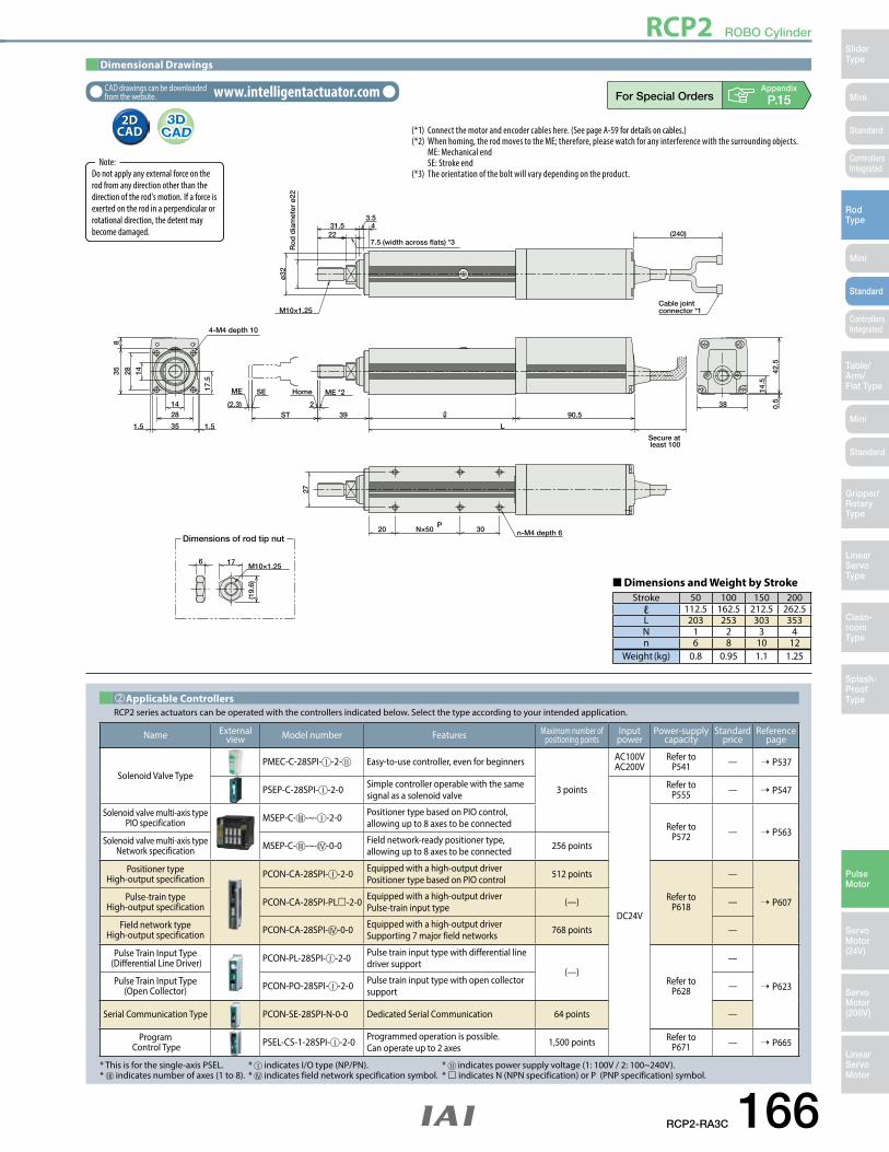
RCP2 ROBO Cylinder
RCP2-RA3C 166
Mini
Mini
Mini
SliderType
RodType
Table/Arm/Flat Type
Linear ServoType
Gripper/Rotary Type
Clean-room Type
Splash-ProofType
Pulse Motor
Servo Motor (24V)
Servo Motor (200V)
LinearServo Motor
Standard
Standard
Standard
ControllersIntegrated
ControllersIntegrated
Dimensions of rod tip nutn-M4 depth 6
6
(19.
6)
17 M10×1.25
1428
351.5 1.5
14
17.5
2835
38
14.5
0.5
42.5
4-M4 depth 10
(2.3) 2ST 39 90.5
L
Secure at least 100
20 N×50P
30
27
ME SE ME *2Home
7.5 (width across flats) *3
43.5
31.522
Ro
d d
iam
eter
ø22
ø32
M10×1.25
8
Cable jointconnector *1
(240)
Dimensional Drawings
CAD drawings can be downloaded from the website. www.intelligentactuator.com
2D CAD2D
CAD (*1) Connect the motor and encoder cables here. (See page A-59 for details on cables.)(*2) When homing, the rod moves to the ME; therefore, please watch for any interference with the surrounding objects. ME: Mechanical end SE: Stroke end(*3) The orientation of the bolt will vary depending on the product.Do not apply any external force on the
rod from any direction other than the direction of the rod's motion. If a force is exerted on the rod in a perpendicular or rotational direction, the detent may become damaged.
Note:
Name Externalview Model number Features Maximum number of
positioning pointsInputpower
Power-supply capacity
Standardprice
Reference page
Solenoid Valve TypePMEC-C-28SPI- -2- Easy-to-use controller, even for beginners
3 points
AC100VAC200V
Refer to P541 — ➝ P537
PSEP-C-28SPI- -2-0 Simple controller operable with the same signal as a solenoid valve
DC24V
Refer to P555 — ➝ P547
Solenoid valve multi-axis type PIO specification MSEP-C- -~- -2-0 Positioner type based on PIO control,
allowing up to 8 axes to be connected Refer to P572 — ➝ P563
Solenoid valve multi-axis type Network specification MSEP-C- -~- -0-0 Field network-ready positioner type,
allowing up to 8 axes to be connected 256 points
Positioner typeHigh-output specification PCON-CA-28SPI- -2-0 Equipped with a high-output driver
Positioner type based on PIO control 512 points
Refer to P618
—
➝ P607Pulse-train typeHigh-output specification PCON-CA-28SPI-PL-2-0 Equipped with a high-output driver
Pulse-train input type (—) —
Field network typeHigh-output specification PCON-CA-28SPI- -0-0 Equipped with a high-output driver
Supporting 7 major field networks 768 points —
Pulse Train Input Type (Differential Line Driver) PCON-PL-28SPI- -2-0 Pulse train input type with differential line
driver support(—)
Refer to P628
—
➝ P623Pulse Train Input Type (Open Collector) PCON-PO-28SPI- -2-0 Pulse train input type with open collector
support —
Serial Communication Type PCON-SE-28SPI-N-0-0 Dedicated Serial Communication 64 points —
Program Control Type PSEL-CS-1-28SPI- -2-0 Programmed operation is possible.
Can operate up to 2 axes 1,500 points Refer to P671 — ➝ P665
* This is for the single-axis PSEL. * indicates I/O type (NP/PN). * indicates power supply voltage (1: 100V / 2: 100~240V).* indicates number of axes (1 to 8). * indicates field network specification symbol. * indicates N (NPN specification) or P (PNP specification) symbol.
RCP2 series actuators can be operated with the controllers indicated below. Select the type according to your intended application.Applicable Controllers
■ Dimensions and Weight by Stroke Stroke 50 100 150 200
ℓ 112.5 162.5 212.5 262.5L 203 253 303 353N 1 2 3 4n 6 8 10 12
Weight (kg) 0.8 0.95 1.1 1.25
Appendix
P.15

RCP2 ROBO Cylinder RCP2 ROBO Cylinder
167 RCP2-RA8C
Mini
Mini
Mini
SliderType
RodType
Table/Arm/
Flat Type
Linear ServoType
Gripper/Rotary
Type
Clean-room Type
Splash-ProofType
Pulse Motor
Servo Motor (24V)
Servo Motor (200V)
LinearServo Motor
Standard
Standard
Standard
ControllersIntegrated
ControllersIntegrated
120
100
80
60
40
20
00 50 100 150 200 250 300 Speed (mm/sec) Operated with the PCON-CFA
Payl
oad
(kg)
5mm lead
10mm lead
10
RCP2-RA8C Holizontal
80
70
60
50
40
30
20
10
00 50 100 150 200 250 300 Speed (mm/sec) Operated with the PCON-CFA
Payl
oad
(kg)
3 2
5mm lead
10mm lead
RCP2-RA8C Vertical
n Speed vs. Load Capacity
Appendix
P.5
P
O I N T
Notes on Selection
(1) The load capacity is based on operation at an acceleration of 0.1G for 5mm-lead, and 0.2G for 10mm-lead. These values are the upper limits for the acceleration.(2) Please note that the controller for the RA8C will be the PCON-CFA (for high-thrust motors).(3) The horizontal load capacity is based on the use of an external guide.(4) See page A-71 for details on push motion.
Item DescriptionDrive method Ball screw, ø16mm, rolled C10Positioning repeatability ±0.02mmLost motion 0.1mm or lessRod ø40mm Stainless steel pipeRod non-rotation precision ±1.0 deg Ambient operating temperature/humidity 0 to 40°C, 85% RH max. (Non-condensing)
Actuator SpecificationsName Option code Page Standard Prices
Connector cable exit direction A1 ~ A3 ➝ A-41 —Brake B ➝ A-42 —Flange FL ➝ A-44 —Foot bracket FT ➝ A-48 —Non-motor end specification NM ➝ A-52 —
➂Options
Model number Lead(mm)
Connectioncable
Maximum payload Maximum pushing force (N)
Stroke(mm)Horizontal (kg) Vertical (kg)
RCP2-RA8C-I-60P-10- ➀ -P4- ➁ - ➂ 10 PCON-CFA 60 40 1,000 50 to 300
(every 50mm)RCP2-RA8C-I-60P-5- ➀ -P4- ➁ - ➂ 5 PCON-CFA 100 70 2,000
Actuator Specifications■ Leads and Payloads ■ Stroke and Maximum Speed
Code explanation ➀ Stroke ➁ Cable length ➂ Options *See page A-71 for details on push motion.
Stroke 50~300(every 50mm)Lead
10 300
5 150
(Unit: mm/s)
Type Cable symbol Standard price
Standard typeP (1m) —S (3m) —M (5m) —
Special lengthX06 (6m) ~ X10 (10m) —X11 (11m) ~ X15 (15m) —X16 (16m) ~ X20 (20m) —
Robot cable
R01 (1m) ~ R03 (3m) —R04 (4m) ~ R05 (5m) —R06 (6m) ~ R10 (10m) —R11 (11m) ~ R15 (15m) —R16 (16m) ~ R20 (20m) —
* See page A-59 for cables for maintenance.
➁Cable Length
➀Stroke (mm) Standard price
50 —100 —150 —200 —250 —300 —
➀Stroke
RCP2-RA8C 60P: Pulse motor, 60size
10: 10mm5: 5mm
50: 50mm
300: 300mm(every 50mm)
RCS2Series Type Encoder type Cable lengthMotor type
60PLead Stroke OptionsApplicable controller
I
I: Incremental P4: PCON-CFA N: None P: 1m S: 3m M: 5mX: Custom length X: Robot cable
See Options below.
* See page Pre-47 for details on the model descriptions.
RA8CModel SpecificationItems
RCP2
ROBO Cylinder, High-Thrust Rod Type, Motor Unit Coupled, Actuator Width 85mm, 24-V Pulse Motor
P4

RCP2 ROBO Cylinder RCP2 ROBO Cylinder
RCP2-RA8C 168
Mini
Mini
Mini
SliderType
RodType
Table/Arm/Flat Type
Linear ServoType
Gripper/Rotary Type
Clean-room Type
Splash-ProofType
Pulse Motor
Servo Motor (24V)
Servo Motor (200V)
LinearServo Motor
Standard
Standard
Standard
ControllersIntegrated
ControllersIntegrated
4 34.5 1111540S.E.M.E.
67
67 86
85
43.5
55
35 50 50 Ax100
60
550 85
10016
67120 67
(B)
L
(2.6)
(67)
st+124.5
st+124.5
34.5 50 11135 D
100
130
25
1686
(18)
30M20x1.5 12
4-ø8.5, through
Dimensions of thefoot bracket type 4-ø8.5, through
st+320 (Brake)
C-M8, depth 16
2-ø5H7, reamed, depth 5
(Ream
er pit
ch±0
.02)
12 (Across flats area)
ME(*2)
4Home
st
35 (E�ective thread)
M20x1.5
ø40 (
Oute
r diam
eter
of ro
d)
ø70
Secure at least 100mm
Cable joint connector *1
(18)
(34.
6)
4-M8, depth 16
27
(Acr
oss f
lats
are
a) (*
3)
Dimensions of the rod tip nut
Dimensions of the flange type Dimensions of the brake type
Load (kg)
10 50403020 60 70
6,000
5,000
4,000
3,000
1,000
2,000
00
48.5kg
Serv
ice
life
(km
)
Relationship of payload and service life (lead 5, used vertically)
Dimensional Drawings
CAD drawings can be downloaded from the website. www.intelligentactuator.com
2D CAD2D
CAD(*1) Connect the motor and encoder cables here.(*2) During home return, the rod will move all the way to the ME. Accordingly, pay attention to prevent possible contact between the rod and surrounding parts during home return. ME: Mechanical End SE: Stroke End Reference dimensions are shown in parentheses.
(*3) The orientation of the bolt will vary depending on the product.(*4) When installing the actuator by using flange and front housing, be careful not to apply external force to the main body. ME : Mechanical end SE : Stroke end
Do not apply any external force on the rod from any direction other than the direction of the rod's motion. If a force is exerted on the rod in a perpendicular or rotational direction, the detent may become damaged.
Note:
Stroke 50 100 150 200 250 300L 320 370 420 470 520 570A 0 0 1 1 2 2B 39.5 89.5 39.5 89.5 39.5 89.5C 6 6 8 8 10 10D 100 100 200 200 300 300
Weight (kg)
without brake 6.5 7.4 8.2 9.1 9.9 10.7with brake 7.5 8.4 9.2 10.1 10.9 11.7
■ Dimensions and Weights by Stroke (mm)
Name Externalview Model number Features Maximum number of
positioning pointsInputpower
Power-supply capacity
Standardprice
Reference page
Positioner type PCON-CFA-60PI-NP--0-PCON-CFA-60PI-PN--0-
Equipped with a high-output driverPositioner type based on PIO control 512 points
DC24V Refer to P618
—
➝ P607Pulse-train type PCON-CFA-60PI-PLN--0-PCON-CFA-60PI-PLP--0-
Equipped with a high-output driverPulse-train input type (—) —
Field network type PCON-CFA-60PI- -0-0- Equipped with a high-output driverSupporting 7 major field networks 768 points —
* indicates field network specification symbol (DV, CC, PR, CN, ML, EC, EP).
RCP2 series actuators can be operated with the controllers indicated below. Select the type according to your intended application.
Applicable Controllers
Appendix
P.15

RCP2 ROBO Cylinder
169 RCP2-RA8R
Mini
Mini
Mini
SliderType
RodType
Table/Arm/
Flat Type
Linear ServoType
Gripper/Rotary
Type
Clean-room Type
Splash-ProofType
Pulse Motor
Servo Motor (24V)
Servo Motor (200V)
LinearServo Motor
Standard
Standard
Standard
ControllersIntegrated
ControllersIntegrated
80
70
60
50
40
30
20
10
00 50 100 150 200 250 300
Speed (mm/sec) Operated with the PCON-CFAPa
yloa
d (k
g)
15
4
10mm lead
5mm lead
120
100
80
60
40
20
00 50 100 150 200 250 300
Speed (mm/sec) Operated with the PCON-CFA
Payl
oad
(kg)
5mm lead
10mm lead75
12
RCP2-RA8R Horizontal
RCP2-RA8R Vertical
n Speed vs. Load Capacity
Item DescriptionDrive method Ball screw, ø16mm, rolled C10Positioning repeatability ±0.02mmLost motion 0.1mm or lessRod ø40mm Stainless steel pipeRod non-rotation precision ±1.0 deg Ambient operating temperature/humidity 0 to 40°C, 85% RH max. (Non-condensing)
Actuator SpecificationsName Option code Page Standard Prices
Connector cable exit direction A1 ~ A3 ➝ A-41 —Brake B ➝ A-42 —Flange FL ➝ A-44 —Foot bracket FT ➝ A-48 —Non-motor end specification NM ➝ A-52 —Side-mounted motor at the top MT1/MT2/MT3 ➝ A-57 —Side-mounted motor to the right MR1/MR2 ➝ A-57 —Side-mounted motor to the left ML1/ML3 ➝ A-57 —
➂Options
■ Stroke and Maximum Speed
Model number Lead(mm)
Connectioncable
Maximum payload Maximum pushing force (N
Stroke(mm)Horizontal (kg) Vertical (kg)
RCP2-RA8R-I-60P-10- ➀ -P4- ➁ - ➂ 10 PCON-CFA 60 40 1,000 50 to 300
(every 50mm)RCP2-RA8R-I-60P-5- ➀ -P4- ➁ - ➂ 5 PCON-CFA 100 70 2,000
Actuator Specifications■ Leads and Payloads
Code explanation ➀ Stroke ➁ Cable length ➂ Options *See page A-71 for details on push motion.
Stroke 50~300(every 50mm)Lead
10 200
5 100
(Unit: mm/s)
Type Cable symbol Standard price
Standard typeP (1m) —S (3m) —M (5m) —
Special lengthX06 (6m) ~ X10 (10m) —X11 (11m) ~ X15 (15m) —X16 (16m) ~ X20 (20m) —
Robot cable
R01 (1m) ~ R03 (3m) —R04 (4m) ~ R05 (5m) —R06 (6m) ~ R10 (10m) —R11 (11m) ~ R15 (15m) —R16 (16m) ~ R20 (20m) —
* See page A-59 for cables for maintenance.
➁Cable Length
➀Stroke (mm) Standard price
50 —100 —150 —200 —250 —300 —
➀Stroke
RCP2-RA8R 60P: Pulse motor, 60size
10: 10mm5: 5mm
50: 50mm
300: 300mm(every 50mm)
ROBO Cylinder, High-Thrust Rod Type, Side-mounted Motor Type, Actuator Width 85mm, 24-V Pulse Motor
RCS2Series Type Encoder type Cable lengthMotor type
60PLead Stroke OptionsApplicable controller
I P4
I: Incremental P4: PCON-CFA N: None P: 1m S: 3m M: 5mX: Custom length X: Robot cable
See Options below.
* Please specify side-mounted motor direction by an option code.* See page Pre-47 for details on the model descriptions.
RA8RModel SpecificationItems
RCP2
P
O I N T
Notes on Selection
(1) The load capacity is based on operation at an acceleration of 0.1G for 5mm-lead, and 0.2G for 10mm-lead. These values are the upper limits for the acceleration.(2) Please note that the controller for the RA8R will be the PCON-CFA (for high-thrust motors).(3) The horizontal load capacity is based on the use of an external guide.(4) See page A-71 for details on push motion.
Appendix
P.5

RCP2 ROBO Cylinder
RCP2-RA8R 170
Mini
Mini
Mini
SliderType
RodType
Table/Arm/Flat Type
Linear ServoType
Gripper/Rotary Type
Clean-room Type
Splash-ProofType
Pulse Motor
Servo Motor (24V)
Servo Motor (200V)
LinearServo Motor
Standard
Standard
Standard
ControllersIntegrated
ControllersIntegrated
S.E.M.E.4 15 st+124.5 47
L
208.5
3020.5110
6785
671
176
43.5
67 86
6785
177
50
(17)
(17)
(67)
(43.
5)
85
100 1667120
Dimensions of the flange type
1617
7
35
67
111247
4768.520.5
D
100
130
25
Dimensions of thefoot bracket type Dimensions of the brake type
4-ø8.5, through
4-ø8.5, through
st+171.5
(B)Ax100505035
60
(Ream
er pit
ch±0
.02)
55
2-ø5H7, reamed, depth 5
C-M8, depth 16
4-M8, depth 16
Secure at least 100mm
Cable joint connector *1
ø70
5
4-M8, depth 16
27
(Acr
oss f
lats
are
a) (*
3)
st
Home ME(*2)
4
4012 (Across flats area)
ø40 (
Oute
r diam
eter
of ro
d)
35 (E�ective thread) M20x1.5
30M20x1.5 12
(34.
6)
Dimensions of the rod tip nut
Load (kg)
10 50403020 60 70
6,000
5,000
4,000
3,000
1,000
2,000
00
48.5kg
Serv
ice
life
(km
)
Relationship of payload and service life (lead 5, used vertically)
Do not apply any external force on the rod from any direction other than the direction of the rod's motion. If a force is exerted on the rod in a perpendicular or rotational direction, the detent may become damaged.
Note:
Name Externalview Model number Features Maximum number of
positioning pointsInputpower
Power-supply capacity
Standardprice
Reference page
Positioner type PCON-CFA-60PI-NP--0-PCON-CFA-60PI-PN--0-
Equipped with a high-output driverPositioner type based on PIO control 512 points
DC24V Refer to P618
—
➝ P607Pulse-train type PCON-CFA-60PI-PLN--0-PCON-CFA-60PI-PLP--0-
Equipped with a high-output driverPulse-train input type (—) —
Field network type PCON-CFA-60PI- -0-0- Equipped with a high-output driverSupporting 7 major field networks 768 points —
* indicates field network specification symbol (DV, CC, PR, CN, ML, EC, EP).
RCP2 series actuators can be operated with the controllers indicated below. Select the type according to your intended application.
Applicable Controllers
Stroke 50 100 150 200 250 300L 221.5 271.5 321.5 371.5 421.5 471.5A 0 0 1 1 2 2B 39.5 89.5 39.5 89.5 39.5 89.5C 6 7 8 8 10 10D 100 100 200 200 300 300
Weight (kg)
without brake 7.7 8.6 9.4 10.3 11.1 12with brake 8.6 9.5 10.3 11.2 12.0 12.9
■ Dimensions and Weights by Stroke (mm)
Dimensional Drawings
CAD drawings can be downloaded from the website. www.intelligentactuator.com
2D CAD2D
CAD
Appendix
P.15(*1) Connect the motor and encoder cables here.(*2) When homing, the rod moves to the ME; therefore, please watch for any interference with the surrounding objects. (*3) The orientation of the bolt will vary depending on the product.(*4) When installing the actuator by using flange and front housing, be careful not to apply external force to the main body. ME : Mechanical end SE : Stroke end

RCP2 ROBO Cylinder
171 RCP2-RA10C
Mini
Mini
Mini
SliderType
RodType
Table/Arm/
Flat Type
Linear ServoType
Gripper/Rotary
Type
Clean-room Type
Splash-ProofType
Pulse Motor
Servo Motor (24V)
Servo Motor (200V)
LinearServo Motor
Standard
Standard
Standard
ControllersIntegrated
ControllersIntegrated
Speed (mm/s)
Speed (mm/s)
10
100
1000
0 50 100 150 200 250 300
Horizontal
5mm lead
10mm lead
2.5mm lead
5mm lead
5mm lead5mm lead
10mm lead
10mm lead10mm lead
2.5mm lead
2.5mm lead2.5mm lead
1
10
100
1000
0 50 100 150 200
Vertical
300
150
80
15
150
80
36
10Lo
ad C
apac
ity (k
g)
Load
Cap
acity
(kg
)
Speed (mm/s)
Speed (mm/s)
10
100
1000
0 50 100 150 200 250 300
Horizontal
5mm lead
10mm lead
2.5mm lead
5mm lead
5mm lead5mm lead
10mm lead
10mm lead10mm lead
2.5mm lead
2.5mm lead2.5mm lead
1
10
100
1000
0 50 100 150 200
Vertical
300
150
80
15
150
80
36
10
Load
Cap
acity
(kg
)Lo
ad C
apac
ity (k
g)
P
O I N T
Notes on Selection
(1) Minimum speed is set per each lead. (10mm-lead: 10mm/s, 5mm-lead: 5mm/s, 2.5-lead: 1mm/s) Please note that if the actuator is operated below the minimum speed, vibration may occur.(2) Since the RCP2 series use a pulse motor, the load capacity decreases at high speeds. Check in the Speed vs. Load Capacity graph to see if your desired speed and load capacity are supported. (3) The load capacity is based on operation at an acceleration of 0.04G for 10mm-lead, 0.02G for 5mm-lead, and 0.01G for 2.5-lead. This is the upper limit of the acceleration. In addition, the horizontal load capacity is based on the use of an external guide. If an external force is exerted on the rod from a direction other than the motion of the rod, the detent may become damaged. (4) See page A-71 for details on push motion.
Appendix
P.5
n Speed vs. Load CapacityDue to the characteristics of the pulse motor, the RCP2 series' load capacity decreases at high speeds. In the table below, check if your desired speed and load capacity are supported.
Item DescriptionDrive method Ball screw, ø20mm, rolled C10Positioning repeatability ±0.02mmLost motion 0.1mm or lessRod diameter ø40mmRod non-rotation precision ±1.0 deg Ambient operating temperature/humidity 0 to 40°C, 85% RH max. (Non-condensing)
Actuator SpecificationsName Option code Page Standard Price
Connector cable exit direction A1 ~ A3 ➝ A-41 —Brake B ➝ A-42 —Flange FL ➝ A-46 —Foot bracket FT ➝ A-48 —
➂Options
* See page A-59 for cables for maintenance.
Type Cable symbol Standard price
Standard typeP (1m) —S (3m) —M (5m) —
Special lengthX06 (6m) ~ X10 (10m) —X11 (11m) ~ X15 (15m) —X16 (16m) ~ X20 (20m) —
Robot cable
R01 (1m) ~ R03 (3m) —R04 (4m) ~ R05 (5m) —R06 (6m) ~ R10 (10m) —R11 (11m) ~ R15 (15m) —R16 (16m) ~ R20 (20m) —
➁Cable Length
➀Stroke (mm) Standard price
50 —100 —150 —200 —250 —300 —
➀Stroke
Model number Lead(mm)
Maximum payload (Note 1) Positioning repeatability
(mm)Stroke
(mm)Horizontal (kg) Vertical (kg)
RCP2-RA10C-1-86P-10- ➀ -P4- ➁ - ➂ 10 ~80 ~80 1,50050 to 300
(every 50mm)
RCP2-RA10C-1-86P-5- ➀ -P4- ➁ - ➂ 5 150 ~100 3,000
RCP2-RA10C-1-86P-2.5- ➀ -P4- ➁ - ➂ 2.5 300 ~150 6,000
Actuator Specifications■ Leads and Payloads ■ Stroke and Maximum Speed
Legend ➀ Stroke ➁ Cable length ➂ Options *See page A-71 for details on push motion.
Stroke 50~300(every 50mm)Lead
10 250 <167>
5 125
2.5 63
(Unit: mm/s)The values in < > apply when the actuator is used vertically.
(Note 1) Please note that the maximum load capacity decreases as the speed increases.
RCP2-RA10C ROBO Cylinder, High-Thrust Rod Type, Actuator Width 100mm, Pulse Motor, Straight Type
RCS2Series Type Encoder type Cable lengthMotor type
86PLead Stroke OptionsApplicable controller
I P4
86P: Pulse motor, size 86
P4: PCON-CFA N: NoneP: 1mS: 3mM: 5mX : Custom lengthR : Robot cable
See Options below.50: 50mm
300: 300mm(50mm pitch increments)
10: 10mm5: 5mm
2.5: 2.5mm
* See page Pre-47 for details on the model descriptions.
RA10CModel SpecificationItems
RCP2
I: Incremental

RCP2 ROBO Cylinder
RCP2-RA10C 172
Mini
Mini
Mini
SliderType
RodType
Table/Arm/Flat Type
Linear ServoType
Gripper/Rotary Type
Clean-room Type
Splash-ProofType
Pulse Motor
Servo Motor (24V)
Servo Motor (200V)
LinearServo Motor
Standard
Standard
Standard
ControllersIntegrated
ControllersIntegrated
52.5 45.5 117.5
(1)
ST+11537
37 (effective screw section)
26
L
117.5
(200)
52.5
95
80
32
M22×1.5
37
13
4-M10 depth 18
100
100 Home ME *2ME SE
(1)
ø70
h10
4-M10 through40
M22×1.5
13.5 (width across flats) *3
5
27.5
5 Effective ST (81)5
ST+16020
40
80
Cable jointconnector *1
Dimensions of the supplied nut
Dimensions of the brake section
10000
5000
1000
100
10
Vertical payload (kg)
2.5 lead type 5 lead type 10 lead type
39kg rated 51kg rated150kg max 100kg max 47kg rated 80kg max.
0 25 50 75 100 125 150
10000
5000
1000
100
10
Vertical payload (kg)0 25 50 75 100
Vertical payload (kg)20 40 60 80
10000
5000
1000
100
10
0
Ser
vice
life
(km
)
Ser
vice
life
(km
)
Ser
vice
life
(km
)
Dimensional Drawings
CAD drawings can be downloaded from the website. www.intelligentactuator.com
2D CAD2D
CAD
(*1) Connect the motor and encoder cables here. Please note that although the motor cable is the same as RCP2 series, the encoder cable is series-specific. (See page A-59 for details on cables.)(*2) During home return, be careful to avoid interference from peripheral objects because the slider travels until the mechanical end. ME : Mechanical end SE : Stroke end The values enclosed in "( )" are reference dimentions.(*3) The orientation of the bolt varies depending on the product.
* The RA10C is not available in non-motor end configuration, due to its construction.
Appendix
P.15
Do not apply any external force on the rod from any direction other than the direction of the rod's motion. If a force is exerted on the rod in a perpendicular or rotational direction, the detent may become damaged.
Note:
The rated value is the maximum value that can meet a service life of 5,000km. The maximum value is the value at which it is still operable. Please note that operation with values exceeding the rated value will result in a decrease in the service life, as shown in the graphs.
Note:
Name Externalview Model number Features Maximum number of
positioning pointsInputpower
Power-supply capacity
Standardprice
Reference page
Positioner type PCON-CFA-86PI-NP--0-PCON-CFA-86PI-PN--0-
Equipped with a high-output driverPositioner type based on PIO control 512 points
DC24V Refer to P618
—
➝ P607Pulse-train type PCON-CFA-86PI-PLN--0-PCON-CFA-86PI-PLP--0-
Equipped with a high-output driverPulse-train input type (—) —
Field network type PCON-CFA-86PI- -0-0- Equipped with a high-output driverSupporting 7 major field networks 768 points —
* indicates field network specification symbol (DV, CC, PR, CN, ML, EC, EP).
RCP2 series actuators can be operated with the controllers indicated below. Select the type according to your intended application.Applicable Controllers
Stroke 50 100 150 200 250 300L 372 422 472 522 572 622
Weight (kg) 9 9.5 10 10.5 11 11.5
■ Dimensions and Weights by Stroke
Vertical Payload and Service Life
● The service life of a rod-type ROBO Cylinder is 5,000km. However, since the RCP2-RA10C has a larger maximum thrust compared to other types, its service life will largely depend on the load capacity and pushing force used. Therefore, when selecting your product using the Speed vs. Load Capacity, or Pushing Force vs. Current Limit graphs, check the service life using the Load Capacity vs. Load Capacity, and Pushing Force vs. Load Capacity graphs.
* Compared to the standard model, the brake-equipped model is longer by 45.5mm and heavier by 1.5kg.

173 RCP2-SRA4R
Mini
Mini
Mini
SliderType
RodType
Table/Arm/
Flat Type
Linear ServoType
Gripper/Rotary
Type
Clean-room Type
Splash-ProofType
Pulse Motor
Servo Motor (24V)
Servo Motor (200V)
LinearServo Motor
Standard
Standard
Standard
ControllersIntegrated
ControllersIntegrated
RCP2 ROBO Cylinder
0
5
10
15
20
25
30
35
40
0 50 100 150 200 250Speed (mm/s)
300
0
2
4
6
8
10
12
14
16
18
20
0 50 100 150 200 250Speed (mm/s)
300
Vertical
Horizontal
5mm lead
2.5mm lead2.5mm lead
5mm lead
2.5mm lead
5mm lead
2.5mm lead15
9
15
9
3
Load
Cap
acity
(kg
)Lo
ad C
apac
ity (k
g)
0
5
10
15
20
25
30
35
40
0 50 100 150 200 250Speed (mm/s)
300
0
2
4
6
8
10
12
14
16
18
20
0 50 100 150 200 250Speed (mm/s)
300
Vertical
Horizontal
5mm lead
2.5mm lead2.5mm lead
5mm lead
2.5mm lead
5mm lead
2.5mm lead15
9
15
9
3
Load
Cap
acity
(kg
)Lo
ad C
apac
ity (k
g)
n Speed vs. Load CapacityDue to the characteristics of the pulse motor, the RCP2 series' load capacity decreases at high speeds. In the table below, check if your desired speed and load capacity are supported.
P
O I N T
Notes on Selection
(1) Since the RCP2 series use a pulse motor, the load capacity decreases at high speeds. Check in the Speed vs. Load Capacity graph to see if your desired speed and load capacity are supported. (2) The load capacity is based on operation at an acceleration of 0.3G (0.2G is for the 2.5mm-lead model, or when used vertically). This is the upper limit of the acceleration. (3) The horizontal load capacity is based on the use of an external guide. If an external force is exerted on the rod from a direction other than the motion of the rod, the detent may become damaged. (4) See page A-71 for details on push motion.
Appendix
P.5
Item DescriptionDrive method Ball screw, ø8mm, rolled C10Positioning repeatability ±0.02mmLost motion 0.1mm or lessRod diameter ø22mmRod non-rotation precision —Ambient operating temperature/humidity 0 to 40°C, 85% RH max. (Non-condensing)
Actuator Specifications
Type Cable symbol Standard price
Standard type(Robot cable)
P (1m) —S (3m) —M (5m) —
Special lengthX06 (6m) ~ X10 (10m) —X11 (11m) ~ X15 (15m) —X16 (16m) ~ X20 (20m) —
* The cable is a motor-encoder integrated cable, and is provided as a robot cable.* See page A-59 for cables for maintenance.
➂Cable Length
➀Stroke (mm) Standard price
25 ~ 50 —60 ~ 100 —
150 —200 —
➀Stroke
Model number Lead(mm)
Maximum payload (Note 1) Positioning repeatability
(mm)Stroke
(mm)Horizontal (kg) Vertical (kg)
RCP2-SRA4R-1-35P-5- ➀ - ➁ - ➂ - ➃ 5 ~25 ~9 112 20 to 200
(every 10mm)(Note 2)RCP2-SRA4R-1-35P-2.5- ➀ - ➁ - ➂ - ➃ 2.5 ~35 ~15 224
Actuator Specifications■ Leads and Payloads ■ Stroke and Maximum Speed
Legend ➀ Stroke ➁ Applicable Controller ➂ Cable length ➃ Options *See page A-71 for details on push motion.
Stroke 20~200(every 10mm)Lead
5 250
2.5 125
(Unit: mm/s)
(Note 1) Please note that the maximum load capacity decreases as the speed increases. (Note 2) 50mm increments over 100mm.
Name Option code Page Standard PriceBrake B ➝ A-42 —Flange bracket (front) FL ➝ A-44 —Flange bracket (rear) FLR ➝ A-46 —Foot bracket 1 (base mounting) FT ➝ A-48 —Foot bracket 2 (right/left side mounting) FT2/FT4 ➝ A-48 —Non-motor end specification NM ➝ A-52 —
➃Options
* The brake is available for strokes of 70mm or more.
RCP2-SRA4R ROBO Cylinder, Short-length Rod Type, Actuator Width 45mm, Pulse Motor, Side-mounted Motor
RCS2Series Type Encoder type Cable lengthMotor type
35PLead Stroke OptionsApplicable controller
I
35P: Pulse motor, size 35
I: Incremental *The Simple absolute encoder is also considered type "I".
P1: PCON-PL/PO/SE PSELP3: PCON-CA PMEC/PSEP MSEP
N: NoneP: 1mS: 3mM: 5mX : Custom length
* See options below.20: 20mm
200: 200mm(10mm pitch increments)
* 50mm increments over 100mm* See page Pre-47 for details on the model descriptions.
SRA4RModel SpecificationItems
RCP2
5: 5mm2.5: 2.5mm

RCP2-SRA4R 174
Mini
Mini
Mini
SliderType
RodType
Table/Arm/Flat Type
Linear ServoType
Gripper/Rotary Type
Clean-room Type
Splash-ProofType
Pulse Motor
Servo Motor (24V)
Servo Motor (200V)
LinearServo Motor
Standard
Standard
Standard
ControllersIntegrated
ControllersIntegrated
RCP2 ROBO Cylinder
6
Dimensions of the Supplied Nut
M10×1.25
(19.
6)
17
4-M6 depth 12
34
34
M10×1.25
ø20
ø22
ø32
7.5 (width across flats)22
31.5 4.8 4.2
4-M6 depth 12
Cable jointconnector (*1)
width across flats (*3)
4534
9550
45 34 14
14
22.5
(210
)
Sec
ure
at le
ast
100
E-M4 depth 10
34
8D×50C24
ME SE ME (*2)Home
E-M4 depth 10(same on the opposite side)
34
C D×50 1517
LA
22B40.5
3
st
3
ST : StrokeSE : Stroke endME: Mechanical end
Dimensional Drawings
CAD drawings can be downloaded from the website. www.intelligentactuator.com
2D CAD2D
CAD
(*1) Connect the motor-encoder integrated cable here. (See page A-59 for details on cables.)(*2) During home return, be careful to avoid interference from peripheral objects because the rod moves until the mechanical end. (*3) The orientation of the bolt varies depending on the product.
Do not apply any external force on the rod from any direction other than the direction of the rod's motion. If a force is exerted on the rod in a perpendicular or rotational direction, the detent may become damaged.
Note:
* This is for the single-axis PSEL. * indicates I/O type (NP/PN). * indicates power supply voltage (1: 100V / 2: 100~240V).* indicates number of axes (1 to 8). * indicates field network specification symbol. * indicates N (NPN specification) or P (PNP specification) symbol.
RCP2 series actuators can be operated with the controllers indicated below. Select the type according to your intended application.Applicable Controllers
Name Externalview Model number Features Maximum number of
positioning pointsInputpower
Power-supply capacity
Standardprice
Reference page
Solenoid Valve TypePMEC-C-35PI- -2- Easy-to-use controller, even for beginners
3 points
AC100VAC200V
Refer to P541 — ➝ P537
PSEP-C-35PI- -2-0 Simple controller operable with the same signal as a solenoid valve
DC24V
Refer to P555 — ➝ P547
Solenoid valve multi-axis type PIO specification MSEP-C- -~- -2-0 Positioner type based on PIO control,
allowing up to 8 axes to be connected Refer to P572 — ➝ P563
Solenoid valve multi-axis type Network specification MSEP-C- -~- -0-0 Field network-ready positioner type,
allowing up to 8 axes to be connected 256 points
Positioner typeHigh-output specification PCON-CA-35PI- -2-0 Equipped with a high-output driver
Positioner type based on PIO control 512 points
Refer to P618
—
➝ P607Pulse-train typeHigh-output specification PCON-CA-35PI-PL-2-0 Equipped with a high-output driver
Pulse-train input type (—) —
Field network typeHigh-output specification PCON-CA-35PI- -0-0 Equipped with a high-output driver
Supporting 7 major field networks 768 points —
Pulse Train Input Type (Differential Line Driver) PCON-PL-35PI- -2-0 Pulse train input type with differential line
driver support(—)
Refer to P628
—
➝ P623Pulse Train Input Type (Open Collector) PCON-PO-35PI- -2-0 Pulse train input type with open collector
support —
Serial Communication Type PCON-SE-35PI-N-0-0 Dedicated Serial Communication 64 points —
Program Control Type PSEL-CS-1-35PI- -2-0 Programmed operation is possible.
Can operate up to 2 axes 1,500 points Refer to P671 — ➝ P665
Appendix
P.15
* The exterior dimensions for the brake-equipped model is no different than the standard model. However, 70mm is the minimum stroke of the brake-equipped models. (i.e. The brake is not compatible at 60mm strokes and under.)
■ Dimensions and Weights by Stroke (Add 0.2kg for brake equipped)
Stroke 20 30 40 50 60 70 80 90 100 150 200L 124.5 134.5 144.5 154.5 164.5 174.5 184.5 194.5 204.5 254.5 304.5A 84 94 104 114 124 134 144 154 164 214 264B 62 72 82 92 102 112 122 132 142 192 242C 30 40 50 60 70 30 40 50 60 60 60D 0 0 0 0 0 1 1 1 1 2 3E 4 4 4 4 4 6 6 6 6 8 10
Weight (kg) 0.83 0.89 0.96 1.02 1.08 1.14 1.21 1.27 1.33 1.64 1.95
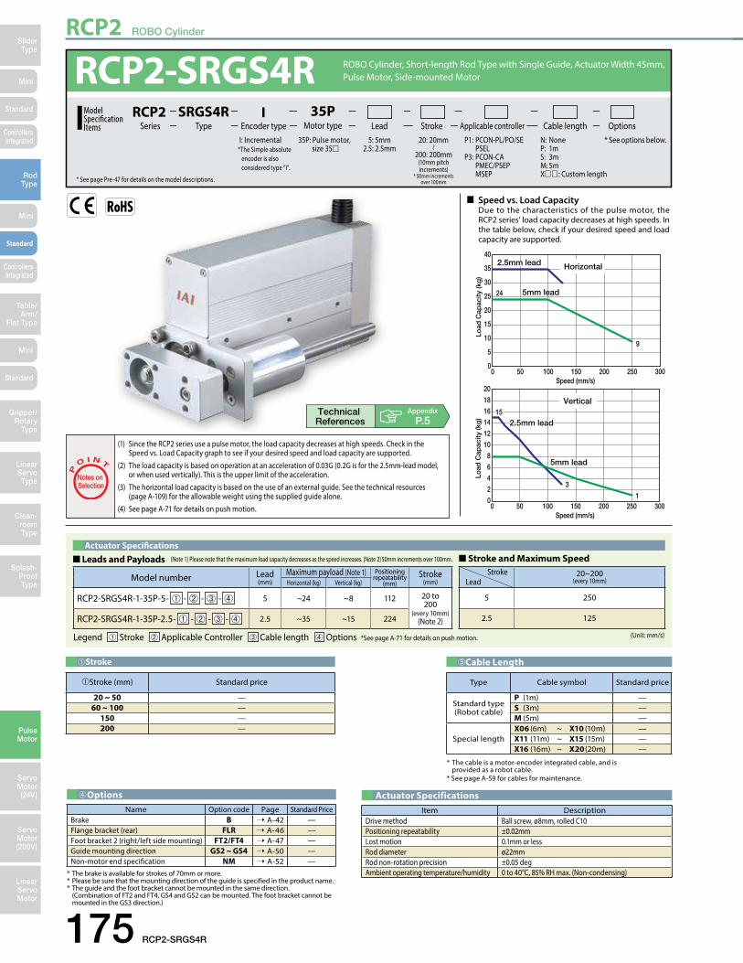
RCP2 ROBO Cylinder
175 RCP2-SRGS4R
Mini
Mini
Mini
SliderType
RodType
Table/Arm/
Flat Type
Linear ServoType
Gripper/Rotary
Type
Clean-room Type
Splash-ProofType
Pulse Motor
Servo Motor (24V)
Servo Motor (200V)
LinearServo Motor
Standard
Standard
Standard
ControllersIntegrated
ControllersIntegrated
0
5
10
15
20
25
30
35
40
0 50 100 150 200 250Speed (mm/s)
300
0
2
4
6
8
10
12
14
16
18
20
0 50 100 150 200 250Speed (mm/s)
300
Vertical
Horizontal
5mm lead
2.5mm lead2.5mm lead
5mm lead
2.5mm lead
5mm lead
2.5mm lead1515
24
9
1
3
Load
Cap
acity
(kg
)Lo
ad C
apac
ity (k
g)
0
5
10
15
20
25
30
35
40
0 50 100 150 200 250Speed (mm/s)
300
0
2
4
6
8
10
12
14
16
18
20
0 50 100 150 200 250Speed (mm/s)
300
Vertical
Horizontal
5mm lead
2.5mm lead2.5mm lead
5mm lead
2.5mm lead
5mm lead
2.5mm lead1515
24
9
1
3Lo
ad C
apac
ity (k
g)
Load
Cap
acity
(kg
)
n Speed vs. Load CapacityDue to the characteristics of the pulse motor, the RCP2 series' load capacity decreases at high speeds. In the table below, check if your desired speed and load capacity are supported.
P
O I N T
Notes on Selection
(1) Since the RCP2 series use a pulse motor, the load capacity decreases at high speeds. Check in the Speed vs. Load Capacity graph to see if your desired speed and load capacity are supported. (2) The load capacity is based on operation at an acceleration of 0.03G (0.2G is for the 2.5mm-lead model, or when used vertically). This is the upper limit of the acceleration. (3) The horizontal load capacity is based on the use of an external guide. See the technical resources (page A-109) for the allowable weight using the supplied guide alone. (4) See page A-71 for details on push motion.
Appendix
P.5
Item DescriptionDrive method Ball screw, ø8mm, rolled C10Positioning repeatability ±0.02mmLost motion 0.1mm or lessRod diameter ø22mmRod non-rotation precision ±0.05 degAmbient operating temperature/humidity 0 to 40°C, 85% RH max. (Non-condensing)
Actuator Specifications
Type Cable symbol Standard price
Standard type(Robot cable)
P (1m) —S (3m) —M (5m) —
Special lengthX06 (6m) ~ X10 (10m) —X11 (11m) ~ X15 (15m) —X16 (16m) ~ X20 (20m) —
* The cable is a motor-encoder integrated cable, and is provided as a robot cable.* See page A-59 for cables for maintenance.
➂Cable Length
➀Stroke (mm) Standard price
20 ~ 50 —60 ~ 100 —
150 —200 —
➀Stroke
Name Option code Page Standard PriceBrake B ➝ A-42 —Flange bracket (rear) FLR ➝ A-46 —Foot bracket 2 (right/left side mounting) FT2/FT4 ➝ A-47 —Guide mounting direction GS2 ~ GS4 ➝ A-50 —Non-motor end specification NM ➝ A-52 —
➃Options
* The brake is available for strokes of 70mm or more.* Please be sure that the mounting direction of the guide is specified in the product name.* The guide and the foot bracket cannot be mounted in the same direction. (Combination of FT2 and FT4, GS4 and GS2 can be mounted. The foot bracket cannot be mounted in the GS3 direction.)
RCP2-SRGS4R5: 5mm
2.5: 2.5mm
ROBO Cylinder, Short-length Rod Type with Single Guide, Actuator Width 45mm, Pulse Motor, Side-mounted Motor
RCS2Series Type Encoder type Cable lengthMotor type
35PLead Stroke OptionsApplicable controller
I
35P: Pulse motor, size 35
I: Incremental *The Simple absolute encoder is also considered type "I".
P1: PCON-PL/PO/SE PSELP3: PCON-CA PMEC/PSEP MSEP
N: NoneP: 1mS: 3mM: 5mX : Custom length
* See options below.20: 20mm
200: 200mm(10mm pitch increments)
* 50mm increments over 100mm* See page Pre-47 for details on the model descriptions.
SRGS4RModel SpecificationItems
RCP2
Model number Lead(mm)
Maximum payload (Note 1) Positioning repeatability
(mm)Stroke
(mm)Horizontal (kg) Vertical (kg)
RCP2-SRGS4R-1-35P-5- ➀ - ➁ - ➂ - ➃ 5 ~24 ~8 112 20 to 200
(every 10mm)(Note 2)RCP2-SRGS4R-1-35P-2.5- ➀ - ➁ - ➂ - ➃ 2.5 ~35 ~15 224
Actuator Specifications■ Leads and Payloads ■ Stroke and Maximum Speed
Legend ➀ Stroke ➁ Applicable Controller ➂ Cable length ➃ Options *See page A-71 for details on push motion.
Stroke 20~200(every 10mm)Lead
5 250
2.5 125
(Unit: mm/s)
(Note 1) Please note that the maximum load capacity decreases as the speed increases. (Note 2) 50mm increments over 100mm.

RCP2 ROBO Cylinder
RCP2-SRGS4R 176
Mini
Mini
Mini
SliderType
RodType
Table/Arm/Flat Type
Linear ServoType
Gripper/Rotary Type
Clean-room Type
Splash-ProofType
Pulse Motor
Servo Motor (24V)
Servo Motor (200V)
LinearServo Motor
Standard
Standard
Standard
ControllersIntegrated
ControllersIntegrated
ST : Stroke
st3 (The amount of shaft movement from the ME on the home-side to the home position)
4-M6 depth 12
34
34
ME SE Home ME (*2)
5.5
ø10
808
2.5
1520
45
4st+6042.5
5 (The amount of shaft overhang at SE)3st
3
E-M4 depth 10
34
8D×50C24
6-M5 depth 12
90.545.5 45
9550
.544
0.5
20 307.5
22.5
53030
E-M4 depth 10(same on the opposite side)
14.520
34L
34.5 8 A22B
15D×50C17
Cable jointconnector (*1)
(210
)
ø34
Sec
ure
at le
ast
100
GS3Bottom-mounted
GS4Left-
mountedActuator
GS2Right-
mounted
(View A)
Guide mounting direction (as viewed from view A)
SE : Stroke endME: Mechanical end
Dimensional Drawings
CAD drawings can be downloaded from the website. www.intelligentactuator.com
2D CAD2D
CAD
(*1) Connect the motor-encoder integrated cable here. (See page A-59 for details on cables.)(*2) When homing, the rod moves to the mechanical end position; therefore, please watch for
any interference with the surrounding objects.
Name Externalview Model number Features Maximum number of
positioning pointsInputpower
Power-supply capacity
Standardprice
Reference page
Solenoid Valve TypePMEC-C-35PI- -2- Easy-to-use controller, even for beginners
3 points
AC100VAC200V
Refer to P541 — ➝ P537
PSEP-C-35PI- -2-0 Simple controller operable with the same signal as a solenoid valve
DC24V
Refer to P555 — ➝ P547
Solenoid valve multi-axis type PIO specification MSEP-C- -~- -2-0 Positioner type based on PIO control,
allowing up to 8 axes to be connected Refer to P572 — ➝ P563
Solenoid valve multi-axis type Network specification MSEP-C- -~- -0-0 Field network-ready positioner type,
allowing up to 8 axes to be connected 256 points
Positioner typeHigh-output specification PCON-CA-35PI- -2-0 Equipped with a high-output driver
Positioner type based on PIO control 512 points
Refer to P618
—
➝ P607Pulse-train typeHigh-output specification PCON-CA-35PI-PL-2-0 Equipped with a high-output driver
Pulse-train input type (—) —
Field network typeHigh-output specification PCON-CA-35PI- -0-0 Equipped with a high-output driver
Supporting 7 major field networks 768 points —
Pulse Train Input Type (Differential Line Driver) PCON-PL-35PI- -2-0 Pulse train input type with differential line
driver support(—)
Refer to P628
—
➝ P623Pulse Train Input Type (Open Collector) PCON-PO-35PI- -2-0 Pulse train input type with open collector
support —
Serial Communication Type PCON-SE-35PI-N-0-0 Dedicated Serial Communication 64 points —
Program Control Type PSEL-CS-1-35PI- -2-0 Programmed operation is possible.
Can operate up to 2 axes 1,500 points Refer to P671 — ➝ P665
* This is for the single-axis PSEL. * indicates I/O type (NP/PN). * indicates power supply voltage (1: 100V / 2: 100~240V).* indicates number of axes (1 to 8). * indicates field network specification symbol. * indicates N (NPN specification) or P (PNP specification) symbol.
RCP2 series actuators can be operated with the controllers indicated below. Select the type according to your intended application.Applicable Controllers
Appendix
P.15
* The exterior dimensions for the brake-equipped model is no different than the standard model. However, 70mm is the minimum stroke of the brake-equipped models. (i.e. The brake is not compatible at 60mm strokes and under.)
■ Dimensions and Weights by Stroke (Add 0.2kg for brake equipped)
Stroke 20 30 40 50 60 70 80 90 100 150 200L 126.5 136.5 146.5 156.5 166.5 176.5 186.5 196.5 206.5 256.5 306.5A 84 94 104 114 124 134 144 154 164 214 264B 62 72 82 92 102 112 122 132 142 192 242C 30 40 50 60 70 30 40 50 60 60 60D 0 0 0 0 0 1 1 1 1 2 3E 4 4 4 4 4 6 6 6 6 8 10
Weight (kg) 1.2 1.27 1.34 1.41 1.48 1.54 1.61 1.68 1.75 2.09 2.43

RCP2 ROBO Cylinder
177 RCP2-SRGD4R
Mini
Mini
Mini
SliderType
RodType
Table/Arm/
Flat Type
Linear ServoType
Gripper/Rotary
Type
Clean-room Type
Splash-ProofType
Pulse Motor
Servo Motor (24V)
Servo Motor (200V)
LinearServo Motor
Standard
Standard
Standard
ControllersIntegrated
ControllersIntegrated
0
5
10
15
20
25
30
35
40
0 50 100 150 200 250Speed (mm/s)
300
0
2
4
6
8
10
12
14
16
18
20
0 50 100 150 200 250Speed (mm/s)
300
Vertical
Horizontal
5mm lead
2.5mm lead2.5mm lead
5mm lead
2.5mm lead
5mm lead
2.5mm lead1515
24
9
1
3
Load
Cap
acity
(kg
)Lo
ad C
apac
ity (k
g)
0
5
10
15
20
25
30
35
40
0 50 100 150 200 250Speed (mm/s)
300
0
2
4
6
8
10
12
14
16
18
20
0 50 100 150 200 250Speed (mm/s)
300
Vertical
Horizontal
5mm lead
2.5mm lead2.5mm lead
5mm lead
2.5mm lead
5mm lead
2.5mm lead1515
24
9
1
3Lo
ad C
apac
ity (k
g)
Load
Cap
acity
(kg
)
P
O I N T
Notes on Selection
(1) Since the RCP2 series use a pulse motor, the load capacity decreases at high speeds. Check in the Speed vs. Load Capacity graph to see if your desired speed and load capacity are supported. (2) The load capacity is based on operation at an acceleration of 0.03G (0.2G is for the 2.5mm-lead model, or when used vertically). This is the upper limit of the acceleration. (3) The horizontal load capacity is based on the use of an external guide. See the technical resources (page A-110) for the allowable weight using the supplied guide alone. (4) See page A-71 for details on push motion.
Appendix
P.5
Item DescriptionDrive method Ball screw, ø8mm, rolled C10Positioning repeatability ±0.02mmLost motion 0.1mm or lessRod diameter ø22mmRod non-rotation precision ±0.05 degAmbient operating temperature/humidity 0 to 40°C, 85% RH max. (Non-condensing)
Actuator Specifications
n Speed vs. Load CapacityDue to the characteristics of the pulse motor, the RCP2 series' load capacity decreases at high speeds. In the table below, check if your desired speed and load capacity are supported.
➀Stroke (mm) Standard price
25 ~ 50 —60 ~ 100 —
150 —200 —
➀Stroke
* The brake is available for strokes of 70mm or more.
RCP2-SRGD4RModel SpecificationItems
ROBO Cylinder, Short-length Rod Type with Double Guide, Actuator Width 45mm, Pulse Motor, Side-mounted Motor
RCS2Series Type Encoder type Cable lengthMotor type
35PLead Stroke OptionsApplicable controller
I
35P: Pulse motor, size 35
I: Incremental *The Simple absolute encoder is also considered type "I".
P1: PCON-PL/PO/SE PSELP3: PCON-CA PMEC/PSEP MSEP
N: NoneP: 1mS: 3mM: 5mX : Custom length
* See options below.20: 20mm
200: 200mm(10mm pitch increments)
* 50mm increments over 100mm* See page Pre-47 for details on the model descriptions.
SRGD4RRCP2
5: 5mm2.5: 2.5mm
* The cable is a motor-encoder integrated cable, and is provided as a robot cable.* See page A-59 for cables for maintenance.
➂Cable Length
Type Cable symbol Standard price
Standard type(Robot cable)
P (1m) —S (3m) —M (5m) —
Special lengthX06 (6m) ~ X10 (10m) —X11 (11m) ~ X15 (15m) —X16 (16m) ~ X20 (20m) —
Model number Lead(mm)
Maximum payload (Note 1) Positioning repeatability
(mm)Stroke
(mm)Horizontal (kg) Vertical (kg)
RCP2-SRGD4R-1-35P-5- ➀ - ➁ - ➂ - ➃ 5 ~24 ~8 112 20 to 200
(every 10mm)(Note 2)RCP2-SRGD4R-1-35P-2.5- ➀ - ➁ - ➂ - ➃ 2.5 ~35 ~15 224
Actuator Specifications■ Leads and Payloads ■ Stroke and Maximum Speed
Legend ➀ Stroke ➁ Applicable Controller ➂ Cable length ➃ Options *See page A-71 for details on push motion.
Stroke 20~200(every 10mm)Lead
5 250
2.5 125
(Unit: mm/s)
(Note 1) Please note that the maximum load capacity decreases as the speed increases. (Note 2) 50mm increments over 100mm.
➃OptionsName Option code Page Standard Price
Brake B ➝ A-42 —Flange bracket (rear) FLR ➝ A-46 —Non-motor end specification NM ➝ A-52 —

RCP2 ROBO Cylinder
RCP2-SRGD4R 178
Mini
Mini
Mini
SliderType
RodType
Table/Arm/Flat Type
Linear ServoType
Gripper/Rotary Type
Clean-room Type
Splash-ProofType
Pulse Motor
Servo Motor (24V)
Servo Motor (200V)
LinearServo Motor
Standard
Standard
Standard
ControllersIntegrated
ControllersIntegrated
ST : Stroke
15.5
7.5
8-M5 depth 12(for mounting work piece)
34
L
14.52034.5 8 A
22B15D×50C17
E-M4 depth 10
8D×50C24
34
ME SE Home ME (*2)
5.5
ø10
ø34
15.5
7.5
4545
4st+6042.55 (shaft overhang at SE) st 3 (Amount of shaft movement from ME to home)3
st
3
34
4-M6 depth 12
34
4-M5(for mounting the actuator)
9550
.50.
544 34 30
7.520
45.545.5 45
136126105
3030 30
E-M4 depth 10(same on the opposite side)
Cable jointconnector (*1)
(210
)
Sec
ure
at le
ast
100
22.5
SE : Stroke endME : Mechanical end
Dimensional Drawings
CAD drawings can be downloaded from the website. www.intelligentactuator.com
2D CAD2D
CAD
Appendix
P.15
Name Externalview Model number Features Maximum number of
positioning pointsInputpower
Power-supply capacity
Standardprice
Reference page
Solenoid Valve TypePMEC-C-35PI- -2- Easy-to-use controller, even for beginners
3 points
AC100VAC200V
Refer to P541 — ➝ P537
PSEP-C-35PI- -2-0 Simple controller operable with the same signal as a solenoid valve
DC24V
Refer to P555 — ➝ P547
Solenoid valve multi-axis type PIO specification MSEP-C- -~- -2-0 Positioner type based on PIO control,
allowing up to 8 axes to be connected Refer to P572 — ➝ P563
Solenoid valve multi-axis type Network specification MSEP-C- -~- -0-0 Field network-ready positioner type,
allowing up to 8 axes to be connected 256 points
Positioner typeHigh-output specification PCON-CA-35PI- -2-0 Equipped with a high-output driver
Positioner type based on PIO control 512 points
Refer to P618
—
➝ P607Pulse-train typeHigh-output specification PCON-CA-35PI-PL-2-0 Equipped with a high-output driver
Pulse-train input type (—) —
Field network typeHigh-output specification PCON-CA-35PI- -0-0 Equipped with a high-output driver
Supporting 7 major field networks 768 points —
Pulse Train Input Type (Differential Line Driver) PCON-PL-35PI- -2-0 Pulse train input type with differential line
driver support(—)
Refer to P628
—
➝ P623Pulse Train Input Type (Open Collector) PCON-PO-35PI- -2-0 Pulse train input type with open collector
support —
Serial Communication Type PCON-SE-35PI-N-0-0 Dedicated Serial Communication 64 points —
Program Control Type PSEL-CS-1-35PI- -2-0 Programmed operation is possible.
Can operate up to 2 axes 1,500 points Refer to P671 — ➝ P665
* This is for the single-axis PSEL. * indicates I/O type (NP/PN). * indicates power supply voltage (1: 100V / 2: 100~240V).* indicates number of axes (1 to 8). * indicates field network specification symbol. * indicates N (NPN specification) or P (PNP specification) symbol.
RCP2 series actuators can be operated with the controllers indicated below. Select the type according to your intended application.Applicable Controllers
(*1) Connect the motor-encoder integrated cable here. (See page A-59 for details on cables.)(*2) When homing, the rod moves to the mechanical end position; therefore, please watch for
any interference with the surrounding objects.
(Add 0.2kg for brake equipped)■ Dimensions and Weights by StrokeStroke 20 30 40 50 60 70 80 90 100 150 200
L 126.5 136.5 146.5 156.5 166.5 176.5 186.5 196.5 206.5 256.5 306.5A 84 94 104 114 124 134 144 154 164 214 264B 62 72 82 92 102 112 122 132 142 192 242C 30 40 50 60 70 30 40 50 60 60 60D 0 0 0 0 0 1 1 1 1 2 3E 4 4 4 4 4 6 6 6 6 8 10
Weight (kg) 1.47 1.55 1.62 1.7 1.77 1.84 1.92 1.99 2.07 2.44 2.81
* The exterior dimensions for the brake-equipped model is no different than the standard model. However, 70mm is the minimum stroke of the brake-equipped models. (i.e. The brake is not compatible at 60mm strokes and under.)

ERC3 ROBO Cylinder
179 ERC3-RA4C
Mini
Mini
Mini
SliderType
RodType
Table/Arm/
Flat Type
Linear ServoType
Gripper/Rotary
Type
Clean-room Type
Splash-ProofType
Pulse Motor
Servo Motor (24V)
Servo Motor (200V)
LinearServo Motor
Standard
Standard
Standard
ControllersIntegrated
ControllersIntegrated
High-output setting enabled (Factory default)
05
1015202530
454035
0 100 200 300 400 500 700 900600 800Speed (mm/s)
0 100 200 300 400 500 700 900600 800Speed (mm/s)
02468
1012
20181614
Paylo
ad (k
g)
Paylo
ad (k
g)
Lead 3Lead 3Lead 3Lead 3
Lead 6Lead 6
Lead 6Lead 6Lead 12Lead 12Lead 12Lead 12
Lead 20Lead 20 Lead 20Lead 2044
111.51.5
4.54.5
116666
5.55.5
1616
HorizontalHorizontal VerticalVertical
0.53.5
The values below are based on operation at 0.3 G.
n Speed vs. Load CapacityDue to the characteristics of the pulse motor, the ERC3 series' load capacity decreases at high speeds. In the table below, check if your desired speed and load capacity are supported.
Appendix
P.5
Type Cable symbol Standard price
Standard(Robot Cables)
P (1m) —S (3m) —M (5m) —
Special length X06 (6m) ~ X10 (10m) —* See page 586 for cables for maintenance.
➂Cable Length
Name Option code Page Standard PriceBrake B ➝ A-42 —Simple absolute specification ABU ➝ A-42 — (*)Flange FL ➝ A-45 —Foot bracket FT ➝ A-48 —Non-motor end specification NM ➝ A-52 —
➃Options
(*) If the simple absolute specification is selected, SE (SIO type) I/O type and the separately sold PIO converter with simple absolute specification (with battery) are required.
Stroke (mm) Standard price
50 —100 —150 —200 —250 —300 —
➀Stroke
Model number Lead(mm)
Maximum payload (Note 1) Maximum push force (N)
Stroke(mm)Horizontal (kg) Vertical (kg)
ERC3-RA4C-I-42P-20- ➀ - ➁ - ➂ - ➃ 20 6 1.5 56
50 to 300
(every 50mm)
ERC3-RA4C-I-42P-12- ➀ - ➁ - ➂ - ➃ 12 25 4.5 93
ERC3-RA4C-I-42P-6- ➀ - ➁ - ➂ - ➃ 6 40 12 185
ERC3-RA4C-I-42P-3- ➀ - ➁ - ➂ - ➃ 3 40 18 370
Actuator Specifications (High-output Setting Enabled)■ Leads and Payloads ■ Stroke and Maximum Speed
Legend ➀ Stroke ➁ I/O type ➂ Cable length ➃ Options *See page A-71 for details on push motion.
Stroke 50~200(every 50mm)
250(mm)
300(mm)Lead
20 800
12 700 695 485
6 450 345 240
3 225 170 120
(Unit: mm/s)
(Note 1) Please note that the maximum load capacity decreases as the speed increases.
P
O I N T
Notes on Selection
(1) If the high-output setting is enabled (factory default), the duty must be limited. (Refer to page A-95.) If the high-output setting is disabled, the payload and maximum speed become lower, but the actuator can be used at a duty of 100%. Refer to the operation manual for information on how to change the high-output setting.(2) Refer to page A-99 for the payload at each speed/acceleration when the high-output setting is enabled. (3) The value for the horizontal load capacity is with an external guide. (4) See page A-71 for details on push motion.
Item DescriptionDrive method Ball screw, ø10mm, rolled C10Positioning repeatability (*) ±0.02mm [±0.03mm]Lost motion (*) 0.1mm or less [0.2mm or less]Rod diameter ø25mmRod non-rotation precision ±1.5 degAmbient operating temperature/humidity 0 to 40°C, 85% RH max. (Non-condensing)
Actuator Specifications
(*) The specification in [ ] applies when the lead is 20mm.
ERC3-RA4CRCS2
Series Type Encoder type Cable length Controller TypeMotor type42P
Lead Stroke OptionsI/O typeI
42: Pulse motor I: Incremental NP: PIO (NPN) typePN: PIO (PNP) typeSE: SIO typePLN: pulse-train (NPN) typePLP: pulse-train (PNP) type
N: None P: 1m S: 3m M: 5mX : Custom length
CN: CON type MC: MEC type
B : BrakeNM : Non-motor endABU : Simple absolute specificationFL : FlangeFT : Foot bracket
50: 50mm
300: 300mm(50mm pitch increments)
20: 20mm12: 12mm 6: 6mm 3: 3mm
* See page Pre-47 for details on the model descriptions.
RA4CModel SpecificationItems
ERC3
Controller-Integrated, Rod Type, Actuator Width 45mm, Pulse Motor, Straight Type

ERC3 ROBO Cylinder
ERC3-RA4C 180
Mini
Mini
Mini
SliderType
RodType
Table/Arm/Flat Type
Linear ServoType
Gripper/Rotary Type
Clean-room Type
Splash-ProofType
Pulse Motor
Servo Motor (24V)
Servo Motor (200V)
LinearServo Motor
Standard
Standard
Standard
ControllersIntegrated
ControllersIntegrated
2D CAD2D
CAD
Dimensional Drawings
CAD drawings can be downloaded from the website. www.intelligentactuator.com Appendix
P.15
I/O typeControllers (Built into the Actuator)
With the ERC3 series, one of the following five types of built-in controllers can be selected depending on the external input/output (I/O) type. Select the type that meets your purpose.
Name Externalview Model number Features Maximum number of
positioning pointsInputpower
Power-supply capacity
Standardprice
Reference page
PIO type (NPN specification) ERC3-RA4C-I-42P---NP--
Simple control type accommodating up to 16 positioning points
16
DC24V
High-output setting
enabled:3.5A rated4.2A max.
High-output setting
disabled:2.2A
— ➝ P577
PIO type (PNP specification) ERC3-RA4C-I-42P---PN--
I/O type supporting inputs/outputs of the
PNP specification often used overseas
16
SIO type ERC3-RA4C-I-42P---SE--
High-function type accommodating up to 512 positioning points (PIO converter is used)
512
Pulse-train type (NPN
specification)ERC3-RA4C-I-42P---PLN--
Pulse-train input type supporting the NPN
specification —
Pulse-train type (PNP
specification)ERC3-RA4C-I-42P---PLP--
Pulse-train input type supporting the PNP
specification—
Dimensions and Mass by StrokeStroke 50 100 150 200 250 300
L 286 336 386 436 486 536 F 142 192 242 292 342 392
Weight (kg) 1.4 1.7 2.0 2.3 2.6 2.9
Teaching port
Cable joint connector *1
27.248
.1186.5
105.742.5
17
(19.
6)
M10×1.25
Supplied rod end nut
66
6
M4
3
173445
55.3
345216
.7
29.5
68.7
A
4.37.3
2.7
4.3
ø25
ø32
453022
M10×1.25
3 339
144L
ME SE 105.7
External view of the brake speci�cationThe overall length of the brake speci�cation is 42.5 mm longer than the standard speci�cation and its mass is 0.4 kg heavier.
Stroke
ME(*2)HOMEF (E�ective range of the T-slot)
Supplied square nut for mounting via the T-slot(4 pcs are supplied)
4-M6 depth 12
22 (W
idth
acr
oss
�ats
, 3 lo
catio
ns)
Detail A
8 (Width across �ats) *3
*1 Connect the power & I/O cable. Refer to page 586 for details on this cable SE: Stroke End ME: Mechanical End
*2 The rod moves to the ME during home return, so pay attention to possible contact with surroundingstructures.
*3 The orientation of the bolt will vary depending on the product.

ERC3 ROBO Cylinder
181 ERC3-RA6C
Mini
Mini
Mini
SliderType
RodType
Table/Arm/
Flat Type
Linear ServoType
Gripper/Rotary
Type
Clean-room Type
Splash-ProofType
Pulse Motor
Servo Motor (24V)
Servo Motor (200V)
LinearServo Motor
Standard
Standard
Standard
ControllersIntegrated
ControllersIntegrated
High-output setting enabled (Factory default)
The values below are based on operation at 0.3 G.
Paylo
ad (k
g)
Paylo
ad (k
g)
0102030405060
8070
0 100 200 300 400 500 700600Speed (mm/s)
0 100 200 300 400 500 700 900600 800Speed (mm/s)
0
5
10
15
20
25
30Lead 4Lead 4 Lead 4Lead 4
Lead 8Lead 8
Lead 8Lead 8Lead 16Lead 16
Lead 16Lead 16Lead 24Lead 24 Lead 24Lead 24
5555
1313 1515
22 2222
3333
88
17.517.5
2.52.533
HorizontalHorizontal VerticalVerticalPa
yload
(kg)
Paylo
ad (k
g)0
102030405060
8070
0 100 200 300 400 500 700600Speed (mm/s)
0 100 200 300 400 500 700 900600 800Speed (mm/s)
0
5
10
15
20
25
30Lead 4Lead 4 Lead 4Lead 4
Lead 8Lead 8
Lead 8Lead 8Lead 16Lead 16
Lead 16Lead 16Lead 24Lead 24 Lead 24Lead 24
5555
1313 1515
22 2222
3333
88
17.517.5
2.52.533
HorizontalHorizontal VerticalVertical
The values below are based on operation at 0.3 G.
n Speed vs. Load CapacityDue to the characteristics of the pulse motor, the ERC3 series' load capacity decreases at high speeds. In the table below, check if your desired speed and load capacity are supported.
Appendix
P.5
Type Cable symbol Standard price
Standard(Robot Cables)
P (1m) —S (3m) —M (5m) —
Special length X06 (6m) ~ X10 (10m) —* See page 586 for cables for maintenance.
➂Cable Length
Name Option code Page Standard PriceBrake B ➝ A-42 —Simple absolute specification ABU ➝ A-42 — (*)Flange FL ➝ A-45 —Foot bracket FT ➝ A-48 —Non-motor end NM ➝ A-52 —
➃Options
(*) If the simple absolute specification is selected, SE (SIO type) I/O type and the separately sold PIO converter with simple absolute specification (with battery) are required.
Stroke (mm) Standard price
50 —100 —150 —200 —250 —300 —
➀Stroke
Item DescriptionDrive method Ball screw, ø10mm, rolled C10Positioning repeatability (*) ±0.02mm [±0.03mm]Lost motion (*) 0.1mm or less [0.2mm or less]Rod diameter ø25mmRod non-rotation precision ±1.5 degAmbient operating temperature/humidity 0 to 40°C, 85% RH max. (Non-condensing)
Actuator Specifications
(*) The specification in [ ] applies when the lead is 20mm.
ERC3-RA6C
* See page Pre-47 for details on the model descriptions.
Model SpecificationItems
Controller-Integrated, Rod Type, Actuator Width 64mm, Pulse Motor, Straight Type
RCS2Series Type Encoder type Cable length Controller TypeMotor type
56PLead Stroke OptionsI/O type
I
56: Pulse motor I: Incremental NP: PIO (NPN) typePN: PIO (PNP) typeSE: SIO typePLN: pulse-train (NPN) typePLP: pulse-train (PNP) type
N: None P: 1m S: 3m M: 5mX : Custom Length
CN: CON type MC: MEC type
B : BrakeNM : Non-motor endABU : Simple absolute specificationFL : FlangeFT : Foot bracket
50: 50mm
300: 300mm(50mm pitch increments)
24: 24mm16: 16mm 8: 8mm 4: 4mm
RA6CERC3
P
O I N T
Notes on Selection
(1) If the high-output setting is enabled (factory default), the duty must be limited. (Refer to page A-95.) If the high-output setting is disabled, the payload and maximum speed become lower, but the actuator can be used at a duty of 100%. Refer to the operation manual for information on how to change the high-output setting.(2) Refer to page A-99 for the payload at each speed/acceleration when the high-output setting is enabled. (3) The value for the horizontal load capacity is with an external guide. (4) See page A-71 for details on push motion.
Model number Lead(mm)
Maximum payload (Note 1) Maximum push force (N)
Stroke(mm)Horizontal (kg) Vertical (kg)
ERC3-RA6C-I-56P-24- ➀ - ➁ - ➂ - ➃ 24 13 3 182
50 to 300
(every 50mm)
ERC3-RA6C-I-56P-16- ➀ - ➁ - ➂ - ➃ 16 40 8 273
ERC3-RA6C-I-56P-8- ➀ - ➁ - ➂ - ➃ 8 55 17.5 547
ERC3-RA6C-I-56P-4- ➀ - ➁ - ➂ - ➃ 4 70 25 1094
Actuator Specifications■ Leads and Payloads ■ Stroke and Maximum Speed
Legend ➀ Stroke ➁ I/O type ➂ Cable length ➃ Options *See page A-71 for details on push motion.
Stroke 50~250(every 50mm)
300(mm)Lead
24 800 <600>
16 700 <560>
8 420 400
4 210 <175> 200 <175>
(Unit: mm/s)
(Note 1) Please note that the maximum load capacity decreases as the speed increases.
* The values enclosed in < > apply to vertical settings.* The values of lead 8 and lead 4 apply when acceleration is at 0.1G.

ERC3 ROBO Cylinder
ERC3-RA6C 182
Mini
Mini
Mini
SliderType
RodType
Table/Arm/Flat Type
Linear ServoType
Gripper/Rotary Type
Clean-room Type
Splash-ProofType
Pulse Motor
Servo Motor (24V)
Servo Motor (200V)
LinearServo Motor
Standard
Standard
Standard
ControllersIntegrated
ControllersIntegrated
25506469
40
507213
85
A
6.510.5
3.6
8
10
10
M6
Supplied square nut for mounting via the T-slot(4 pcs are supplied)
5
22
(25.
4)
M14×1.5
Supplied rod end nut
8
33 176.5L49.5
ME(*2)ME SE SE
227.5134.551
134.5
4540.530.5
M14×1.5
Teaching port
Cable joint connector *1
44.965
.8
Detail A
10 (Width across �ats) (*3)
ø43
ø30
4-M8 depth 16
27 (W
idth
acr
oss �
ats,
3 lo
catio
ns)
Stroke F (E�ective range of the T-slot)
External view of the brake speci�cationThe overall length of the brake speci�cation is 51 mm longer than the standard speci�cation and its mass is 0.5 kg heavier.
2D CAD2D
CAD
Dimensional Drawings
CAD drawings can be downloaded from the website. www.intelligentactuator.com Appendix
P.15
I/O typeControllers (Built into the Actuator)
With the ERC3 series, one of the following five types of built-in controllers can be selected depending on the external input/output (I/O) type. Select the type that meets your purpose.
Name Externalview Model number Features Maximum number of
positioning pointsInputpower
Power-supply capacity
Standardprice
Reference page
PIO type (NPN specification) ERC3-RA6C-I-56P---NP--
Simple control type accommodating up to 16 positioning points
16
DC24V
High-output setting
enabled:3.5A rated4.2A max.
High-output setting
disabled:2.2A
— ➝ P577
PIO type (PNP specification) ERC3-RA6C-I-56P---PN--
I/O type supporting inputs/outputs of the
PNP specification often used overseas
16
SIO type ERC3-RA6C-I-56P---SE--
High-function type accommodating up to 512 positioning points (PIO converter is used)
512
Pulse-train type (NPN
specification)ERC3-RA6C-I-56P---PLN--
Pulse-train input type supporting the NPN
specification —
Pulse-train type (PNP
specification)ERC3-RA6C-I-56P---PLP--
Pulse-train input type supporting the PNP
specification —
Dimensions and Mass by StrokeStroke 50 100 150 200 250 300
L 334.5 384.5 434.5 484.5 534.5 584.5F 158 208 258 308 358 408
Weight (kg) 3.9 4.4 4.9 5.4 5.9 6.4
*1 Connect the power & I/O cable. Refer to page 586 for details on this cable SE: Stroke End ME: Mechanical End
*2 The rod moves to the ME during home return, so pay attention to possible contact with surroundingstructures.
*3 The orientation of the bolt will vary depending on the product.

ERC2 ROBO Cylinder
183 ERC2-RA6C
Mini
Mini
Mini
SliderType
RodType
Table/Arm/
Flat Type
Linear ServoType
Gripper/Rotary
Type
Clean-room Type
Splash-ProofType
Pulse Motor
Servo Motor (24V)
Servo Motor (200V)
LinearServo Motor
Standard
Standard
Standard
ControllersIntegrated
ControllersIntegrated
00 100 200 300 400 500 600 700
10
20
30
40
50
60
70
0 100 200 300 400 500 600 7000
Speed (mm/s)
Speed (mm/s)
5
10
15
20
25
30
35
12mm lead
6mm lead3mm lead
12mm lead
6mm lead3mm lead
6mm lead
12mm lead
3mm lead
6mm lead
12mm lead
3mm lead
Vertical
Horizontal
25
2.5
2.5 0.5
1818
12
4.5
4
Load
Cap
acity
(kg
)Lo
ad C
apac
ity (k
g)
n Speed vs. Load CapacityDue to the characteristics of the pulse motor, the ERC2 series' load capacity decreases at high speeds. In the table below, check if your desired speed and load capacity are supported.
P
O I N T
Notes on Selection
(1) When the stroke increases, the maximum speed will drop to prevent the ball screw from reaching the critical rotational speed. Use the actuator specification table below to check the maximum speed at the stroke you desire.(2) Since the ERC2 series use a pulse motor, the load capacity decreases at high speeds. Check in the Speed vs. Load Capacity graph to see if your desired speed and load capacity are supported. (3) The load capacity is based on operation at an acceleration of 0.3G (0.2G for the 3mm-lead model, or when used vertically). This is the upper limit of the acceleration.(4) The value for the horizontal load capacity is with an external guide.(5) See page A-71 for details on push motion.
Item DescriptionDrive method Ball screw, ø10mm, rolled C10Positioning repeatability ±0.02mmLost motion 0.1mm or lessRod diameter ø22mm special SUS typeRod non-rotation precision ±1.5 deg Ambient operating temperature/humidity 0 to 40°C, 85% RH max. (Non-condensing)
Actuator SpecificationsName Option code Page Standard Price
Brake B ➝ A-42 —Foot bracket FT ➝ A-47 —Non-motor end specification NM ➝ A-52 —
➃Options
Type Cable symbol Standard price
Standard typeP (1m) —S (3m) —M (5m) —
Special length X06 (6m) ~ X10 (3m) —
Double endedW01 (1m) ~ W03 (5m) —W04 (4m) ~ W05 (10m) —W06 (6m) ~ W10 (10m) —
Robot cableR01 (1m) ~ R03 (3m) —R04 (4m) ~ R05 (5m) —R06 (6m) ~ R10 (10m) —
Double endedRobot cable
RW01 (1m) ~ RW03 (3m) —RW04 (4m) ~ RW05 (5m) —RW06 (6m) ~ RW10 (10m) —
The values in < > apply to the SE type.* See page 606 for cables for maintenance.
➂Cable Length
➀Stroke (mm) Standard price
50 —100 —150 —200 —250 —300 —
➀Stroke
Appendix
P.5
ERC2-RA6C Controller-Integrated, Rod Type, Actuator Width 58mm, Pulse Motor, Straight Type
RCS2Series Type Encoder type Cable lengthMotor type
PMLead Stroke OptionsI/O type
I
PM: Pulse motor I: Incremental NP: PIO (NPN) typePN: PIO (PNP) typeSE: SIO type
N : None P : 1mS : 3m M : 5mX : Custom lengthW : Double-ended cableR : Robot cableRW : Double-ended Robot cable
B : BrakeFT : Foot bracketNM : Non-motor end
50: 50mm
300: 300mm(50mm pitch
increments)
12: 12mm 6: 6mm 3: 3mm
* See page Pre-47 for details on the model descriptions.
RA6CModel SpecificationItems
ERC2
Model number Lead(mm)
Maximum payload (Note 1) Maximum push force (N)
Stroke(mm)Horizontal (kg) Vertical (kg)
ERC2-RA6C-I-PM-12- ➀ - ➁ - ➂ - ➃ 12 ~25 ~4.5 7850 to 300
(every 50mm)
ERC2-RA6C-I-PM-6- ➀ - ➁ - ➂ - ➃ 6 ~40 ~12 157
ERC2-RA6C-I-PM-3- ➀ - ➁ - ➂ - ➃ 3 40 ~18 304
Actuator Specifications■ Leads and Payloads ■ Stroke and Maximum Speed
Code explanation ➀ Stroke ➁ I/O type ➂ Cable length ➃ Options *See page A-71 for details on push motion.
Stroke 50~250(every 50mm)
300(mm)Lead
12 600 500
6 300 250
3 150 125
(Unit: mm/s)
(Note 1) Please note that the maximum load capacity decreases as the speed increases.

ERC2 ROBO Cylinder
ERC2-RA6C 184
Mini
Mini
Mini
SliderType
RodType
Table/Arm/Flat Type
Linear ServoType
Gripper/Rotary Type
Clean-room Type
Splash-ProofType
Pulse Motor
Servo Motor (24V)
Servo Motor (200V)
LinearServo Motor
Standard
Standard
Standard
ControllersIntegrated
ControllersIntegrated
Teaching port
C718 31.7
M8×1.25 nuts (3 types)M8×1.25
2
37.5
20
43.5 118.5
ME*2Home
BStroke L
Ro
d d
iam
eter
ø
22ø
40h7
49.7 A
82
118.5
* Compared to the standard model, the brake-equipped model is longer by 43.5mm and heavier by 0.5kg.
(Note) The actual orientation of the bolt may differ by product.
Brake Specifications Diagram
20
(300)
*1Connect the power and I/O cables.See page 606 for details on cables. *2When homing, the slider moves to the ME; therefore, please watch for any interference with the surrounding objects.ME: Mechanical end
Cable jointconnector *1
Brake unit
4-ø5.5
75.6
544451
27
585444
13 (width
across flats)
Secure at least 100
* The SIO type does not have a teaching port.
PIO Type SIO Type
Stroke 50 100 150 200 250 300L 293.5 343.5 393.5 443.5 493.5 543.5A 175 225 275 325 375 425C 91 141 191 241 291 341
Weight (kg) 1.6 1.7 1.8 2.0 2.1 2.2
Dimensions and Mass by Stroke
2D CAD2D
CAD
Dimensional Drawings
CAD drawings can be downloaded from the website. www.intelligentactuator.com Appendix
P.15
Do not apply any external force on the rod from any direction other than the direction of the rod's motion. If a force is exerted on the rod in a perpendicular or rotational direction, the detent may become damaged.
Note:
I/O type (Controller built into the Actuator) ②I/O typeWith the ERC2 series, one of the following three types of built-in controllers can be selected depending on the external input/output (I/O) type. Select the type that meets your purpose.
Name External view Model number Features Maximum number of positioning points
Input power
Power supply capacity
Standard price
Reference page
PIOType(NPN
Specification)ERC2-RA6C-I-PM---NP--
Simple control type with up to 16-point
positioning16
DC24V 2A max. — ➝ P597
PIOType(PNP
Specification)ERC2-RA6C-I-PM---PN--
Supports the PNP I/O commonly used
overseas.16
SIOType ERC2-RA6C-I-PM---SE--
Field Network Connection Serial
(Gateway unit used)64

ERC2 ROBO Cylinder
185 ERC2-RA7C
Mini
Mini
Mini
SliderType
RodType
Table/Arm/
Flat Type
Linear ServoType
Gripper/Rotary
Type
Clean-room Type
Splash-ProofType
Pulse Motor
Servo Motor (24V)
Servo Motor (200V)
LinearServo Motor
Standard
Standard
Standard
ControllersIntegrated
ControllersIntegrated
00 100 200 300 400 500 600 700
10
20
30
40
50
60
70
0 100 200 300 400 500 600 7000
Speed (mm/s)
Speed (mm/s)
5
10
15
20
25
30
35
16mm lead
8mm lead4mm lead
16mm lead
8mm lead4mm lead
8mm lead
16mm lead
4mm lead
8mm lead
16mm lead
4mm leadVertical
Horizontal
25
55
3.5 2
2 1 0.5
17.517.5
Load
Cap
acity
(kg
)Lo
ad C
apac
ity (k
g)
Appendix
P.5
n Speed vs. Load CapacityDue to the characteristics of the pulse motor, the ERC2 series' load capacity decreases at high speeds. In the table below, check if your desired speed and load capacity are supported.
Item DescriptionDrive method Ball screw, ø12mm, rolled C10Positioning repeatability ±0.02mmLost motion 0.1mm or lessRod diameter ø30mm special SUS typeRod non-rotation precision ±1.5 deg Ambient operating temperature/humidity 0 to 40°C, 85% RH max. (Non-condensing)
Actuator SpecificationsName Option code Page Standard Price
Brake B ➝ A-42 —Foot bracket FT ➝ A-47 —Non-motor end specification NM ➝ A-52 —
➃Options
➀Stroke (mm) Standard price
50 —100 —150 —200 —250 —300 —
➀Stroke
ERC2-RA7CRCS2
Series Type Encoder type Cable lengthMotor typePM
Lead Stroke OptionsI/O typeI
PM: Pulse motor I: Incremental NP: PIO (NPN) typePN: PIO (PNP) typeSE: SIO type
N : None P : 1mS : 3m M : 5mX : Custom lengthW : Double-ended cableR : Robot cableRW : Double-ended Robot cable
B : BrakeFT : Foot bracketNM : Non-motor end
50: 50mm
300: 300mm(50mm pitch
increments)
16: 16mm 8: 8mm 4: 4mm
* See page Pre-47 for details on the model descriptions.
RA7CModel SpecificationItems
ERC2
Controller-Integrated, Rod Type, Actuator Width 68mm, Pulse Motor, Straight TypeP
O I N T
Notes on Selection
(1) When the stroke increases, the maximum speed will drop to prevent the ball screw from reaching the critical rotational speed. Use the actuator specification table below to check the maximum speed at the stroke you desire.(2) Since the ERC2 series use a pulse motor, the load capacity decreases at high speeds. Check in the Speed vs. Load Capacity graph to see if your desired speed and load capacity are supported. (3) The load capacity is based on operation at an acceleration of 0.3G (0.2G for the 4mm-lead model, or when used vertically). This is the upper limit of the acceleration.(4) The value for the horizontal load capacity is with an external guide.(5) See page A-71 for details on push motion.
Type Cable symbol Standard price
Standard typeP (1m) —S (3m) —M (5m) —
Special length X06 (6m) ~ X10 (3m) —
Double endedW01 (1m) ~ W03 (5m) —W04 (4m) ~ W05 (10m) —W06 (6m) ~ W10 (10m) —
Robot cableR01 (1m) ~ R03 (3m) —R04 (4m) ~ R05 (5m) —R06 (6m) ~ R10 (10m) —
Double endedRobot cable
RW01 (1m) ~ RW03 (3m) —RW04 (4m) ~ RW05 (5m) —RW06 (6m) ~ RW10 (10m) —
The values in < > apply to the SE type.* See page 606 for cables for maintenance.
➂Cable Length
Model number Lead(mm)
Maximum payload (Note 1) Maximum push force (N)
Stroke(mm)Horizontal (kg) Vertical (kg)
ERC2-RA7C-I-PM-16- ➀ - ➁ - ➂ - ➃ 16 ~40 ~5 22050 to 300
(every 50mm)
ERC2-RA7C-I-PM-8- ➀ - ➁ - ➂ - ➃ 8 ~50 ~17.5 441
ERC2-RA7C-I-PM-4- ➀ - ➁ - ➂ - ➃ 4 ~55 ~25 873
Actuator Specifications■ Leads and Payloads ■ Stroke and Maximum Speed
Code explanation ➀ Stroke ➁ I/O type ➂ Cable length ➃ Options *See page A-71 for details on push motion.
Stroke 50~300(every 50mm)Lead
16 450 <400>
8 250 <200>
4 125
(Unit: mm/s)* The values enclosed in < > apply to vertical settings.
(Note 1) Please note that the maximum load capacity decreases as the speed increases.

ERC2 ROBO Cylinder
ERC2-RA7C 186
Mini
Mini
Mini
SliderType
RodType
Table/Arm/Flat Type
Linear ServoType
Gripper/Rotary Type
Clean-room Type
Splash-ProofType
Pulse Motor
Servo Motor (24V)
Servo Motor (200V)
LinearServo Motor
Standard
Standard
Standard
ControllersIntegrated
ControllersIntegrated
Brake unit
C921 40
M10×1.5 nuts (3 types)M10×1.5
49
4
51.5
20
118.5
ME*2Home
BStroke L
ø45
h7
61
8.52
A 118.5
* Compared to the standard model, the brake-equipped model is longer by 49mm and heavier by 0.5kg.
Brake Specifications Diagram
(300)
Cable jointconnector*1
Teaching port
20
When homing, the slider moves to the ME; therefore,please watch for any interference with the surrounding objects.
*2
Connect the power and I/O cables. See page 606 for details on cables
*1
ME: Mechanical end
4-ø6.6
647
5032
1
686450
17 (width
across flats)
Secure at least 100
Ro
d d
iam
eter
ø
30
89.6
* The SIO type does not have a teaching port.
PIO Type SIO Type
(Note) The actual orientation of the bolt may differ by product.
Stroke 50 100 150 200 250 300L 312.5 362.5 412.5 462.5 512.5 562.5A 194 244 294 344 394 444C 106 156 206 256 306 356
Weight (kg) 2.7 2.9 3.0 3.2 3.3 3.5
Dimensions and Mass by Stroke
2D CAD2D
CAD
Dimensional Drawings
CAD drawings can be downloaded from the website. www.intelligentactuator.com Appendix
P.15
Do not apply any external force on the rod from any direction other than the direction of the rod's motion. If a force is exerted on the rod in a perpendicular or rotational direction, the detent may become damaged.
Note:
I/O type (Controller built into the Actuator) ②I/O typeWith the ERC2 series, one of the following three types of built-in controllers can be selected depending on the external input/output (I/O) type. Select the type that meets your purpose.
Name External view Model number Features Maximum number of positioning points
Input power
Power supply capacity
Standard price
Reference page
PIOType(NPN
Specification)ERC2-RA7C-I-PM---NP--
Simple control type with up to 16-point
positioning16
DC24V 2A max. — ➝ P597
PIOType(PNP
Specification)ERC2-RA7C-I-PM---PN--
Supports the PNP I/O commonly used
overseas.16
SIOType ERC2-RA7C-I-PM---SE--
Field Network Connection Serial
(Gateway unit used)64

ERC2 ROBO Cylinder
187 ERC2-RGS6C
Mini
Mini
Mini
SliderType
RodType
Table/Arm/
Flat Type
Linear ServoType
Gripper/Rotary
Type
Clean-room Type
Splash-ProofType
Pulse Motor
Servo Motor (24V)
Servo Motor (200V)
LinearServo Motor
Standard
Standard
Standard
ControllersIntegrated
ControllersIntegrated
0 100 200 300 400 500 600 7000
5
10
15
20
25
30
35
00 100 200
Speed (mm/s)
Speed (mm/s)
300 400 500 600 700
10
20
30
40
50
60
70
6mm lead
12mm lead
3mm lead
6mm lead
12mm lead
3mm lead
Vertical
0.5
4.5
12
1818
2.54
12mm lead
6mm lead3mm lead
12mm lead
6mm lead3mm lead
Horizontal
12
25
2.5
Load
Cap
acity
(kg
)Lo
ad C
apac
ity (k
g)
Appendix
P.5
n Speed vs. Load CapacityDue to the characteristics of the pulse motor, the ERC2 series' load capacity decreases at high speeds. In the table below, check if your desired speed and load capacity are supported.
Item DescriptionDrive method Ball screw, ø10mm, rolled C10Positioning repeatability ±0.02mmLost motion 0.1mm or lessRod diameter ø22mm special SUS typeRod non-rotation precision ±1.5 deg Ambient operating temperature/humidity 0 to 40°C, 85% RH max. (Non-condensing)
Actuator SpecificationsName Option code Page Standard Price
Brake B ➝ A-42 —Foot bracket FT ➝ A-47 —Non-motor end specification NM ➝ A-52 —
➃Options
➀Stroke (mm) Standard price
50 —100 —150 —200 —250 —300 —
➀Stroke
P
O I N T
Notes on Selection
(1) When the stroke increases, the maximum speed will drop to prevent the ball screw from reaching the critical rotational speed. Use the actuator specification table below to check the maximum speed at the stroke you desire.(2) Since the ERC2 series use a pulse motor, the load capacity decreases at high speeds. Check in the Speed vs. Load Capacity graph to see if your desired speed and load capacity are supported. (3) The load capacity is based on operation at an acceleration of 0.3G (0.2G for the 3mm-lead model, or when used vertically). This is the upper limit of the acceleration.(4) The value for the horizontal load capacity is with an external guide.(5) See page A-71 for details on push motion.
ERC2-RGS6C Controller-integrated, Rod Type with Single Guide, Actuator Width 58mm, Pulse Motor, Straight Type
RCS2Series Type Encoder type Cable lengthMotor type
PMLead Stroke OptionsI/O type
I
PM: Pulse motor I: Incremental NP: PIO (NPN) typePN: PIO (PNP) typeSE: SIO type
N : None P : 1mS : 3m M : 5mX : Custom lengthW : Double-ended cableR : Robot cableRW : Double-ended Robot cable
B : BrakeFT : Foot bracketNM : Non-motor end
50: 50mm
300: 300mm(50mm pitch
increments)
12: 12mm 6: 6mm 3: 3mm
* See page Pre-47 for details on the model descriptions.
RA6CModel SpecificationItems
ERC2
Model number Lead(mm)
Maximum payload (Note 1) Maximum push force (N)
Stroke(mm)Horizontal (kg) Vertical (kg)
ERC2-RGS6C-I-PM-12- ➀ - ➁ - ➂ - ➃ 12 ~25 ~4.5 7850 to 300
(every 50mm)
ERC2-RGS6C-I-PM-6- ➀ - ➁ - ➂ - ➃ 6 ~40 ~12 157
ERC2-RGS6C-I-PM-3- ➀ - ➁ - ➂ - ➃ 3 40 ~18 304
Actuator Specifications■ Leads and Payloads ■ Stroke and Maximum Speed
Code explanation ➀ Stroke ➁ I/O type ➂ Cable length ➃ Options *See page A-71 for details on push motion.
Stroke 50~250(every 50mm)
300(mm)Lead
12 600 500
6 300 250
3 150 125
(Unit: mm/s)
(Note 1) Please note that the maximum load capacity decreases as the speed increases.
Type Cable symbol Standard price
Standard typeP (1m) —S (3m) —M (5m) —
Special length X06 (6m) ~ X10 (3m) —
Double endedW01 (1m) ~ W03 (5m) —W04 (4m) ~ W05 (10m) —W06 (6m) ~ W10 (10m) —
Robot cableR01 (1m) ~ R03 (3m) —R04 (4m) ~ R05 (5m) —R06 (6m) ~ R10 (10m) —
Double endedRobot cable
RW01 (1m) ~ RW03 (3m) —RW04 (4m) ~ RW05 (5m) —RW06 (6m) ~ RW10 (10m) —
The values in < > apply to the SE type.* See page 606 for cables for maintenance.
➂Cable Length
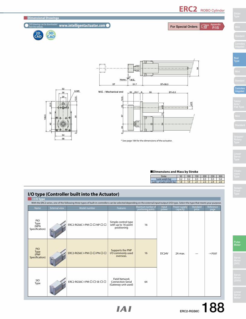
ERC2 ROBO Cylinder
ERC2-RGS6C 188
Mini
Mini
Mini
SliderType
RodType
Table/Arm/Flat Type
Linear ServoType
Gripper/Rotary Type
Clean-room Type
Splash-ProofType
Pulse Motor
Servo Motor (24V)
Servo Motor (200V)
LinearServo Motor
Standard
Standard
Standard
ControllersIntegrated
ControllersIntegrated
106.
5
M.E.Home
54
2
ST 51.7 ST+58.3
1354
ø10
ø34
ST+3.355823.720
12.5
1057
243
22.5
3740
7
12.5
913
58
54
52
30
20
6-M5 M.E. : Mechanical end
Stroke 50 100 150 200 250 300Guide weight (kg) 0.2 0.2 0.3 0.3 0.3 0.4
Guide + actuator weight (kg) 1.8 1.9 2.1 2.3 2.4 2.6
Dimensions and Mass by Stroke
* See page 184 for the dimensions of the actuator.
2D CAD2D
CAD
Dimensional Drawings
CAD drawings can be downloaded from the website. www.intelligentactuator.com Appendix
P.15
I/O type (Controller built into the Actuator) ②I/O typeWith the ERC2 series, one of the following three types of built-in controllers can be selected depending on the external input/output (I/O) type. Select the type that meets your purpose.
Name External view Model number Features Maximum number of positioning points
Input power
Power supply capacity
Standard price
Reference page
PIOType(NPN
Specification)ERC2-RGS6C-I-PM---NP--
Simple control type with up to 16-point
positioning16
DC24V 2A max. — ➝ P597
PIOType(PNP
Specification)ERC2-RGS6C-I-PM---PN--
Supports the PNP I/O commonly used
overseas.16
SIOType ERC2-RGS6C-I-PM---SE--
Field Network Connection Serial
(Gateway unit used)64

ERC2 ROBO Cylinder
189 ERC2-RGS7C
Mini
Mini
Mini
SliderType
RodType
Table/Arm/
Flat Type
Linear ServoType
Gripper/Rotary
Type
Clean-room Type
Splash-ProofType
Pulse Motor
Servo Motor (24V)
Servo Motor (200V)
LinearServo Motor
Standard
Standard
Standard
ControllersIntegrated
ControllersIntegrated
00 100 200 300 400 500 600 700
10
20
30
40
50
60
70
0 100 200 300 400 500 600 7000
Speed (mm/s)
Speed (mm/s)
5
10
15
20
25
30
35
16mm lead
8mm lead
4mm lead
16mm lead
8mm lead
4mm lead
8mm lead
16mm lead
4mm lead
8mm lead
16mm lead
4mm lead
8mm lead
16mm lead
4mm leadVertical
Horizontal
25
55
3.5
2
17.517.5
1 0.5
2
Load
Cap
acity
(kg
)Lo
ad C
apac
ity (k
g)
n Speed vs. Load CapacityDue to the characteristics of the pulse motor, the ERC2 series' load capacity decreases at high speeds. In the table below, check if your desired speed and load capacity are supported.
Item DescriptionDrive method Ball screw, ø12mm, rolled C10Positioning repeatability ±0.02mmLost motion 0.1mm or lessRod diameter ø30mm special SUS typeRod non-rotation precision ±0.05 deg Ambient operating temperature/humidity 0 to 40°C, 85% RH max. (Non-condensing)
Actuator SpecificationsName Option code Page Standard Price
Brake B ➝ A-42 —Foot bracket FT ➝ A-47 —Non-motor end specification NM ➝ A-52 —
➃Options
➀Stroke (mm) Standard price
50 —100 —150 —200 —250 —300 —
➀Stroke
ERC2-RGS7C Controller-integrated, Rod Type with Single Guide, Actuator Width 68mm, Pulse Motor, Straight Type
RCS2Series Type Encoder type Cable lengthMotor type
PMLead Stroke OptionsI/O type
I
PM: Pulse motor I: Incremental NP: PIO (NPN) typePN: PIO (PNP) typeSE: SIO type
N : None P : 1mS : 3m M : 5mX : Custom lengthW : Double-ended cableR : Robot cableRW : Double-ended Robot cable
B : BrakeFT : Foot bracketNM : Non-motor end
50: 50mm
300: 300mm(50mm pitch
increments)
16: 16mm 8: 8mm 4: 4mm
* See page Pre-47 for details on the model descriptions.
RGS7CModel SpecificationItems
ERC2
P
O I N T
Notes on Selection
(1) When the stroke increases, the maximum speed will drop to prevent the ball screw from reaching the critical rotational speed. Use the actuator specification table below to check the maximum speed at the stroke you desire.(2) Since the ERC2 series use a pulse motor, the load capacity decreases at high speeds. Check in the Speed vs. Load Capacity graph to see if your desired speed and load capacity are supported. (3) The load capacity is based on operation at an acceleration of 0.3G (0.2G for the 4mm-lead model, or when used vertically). This is the upper limit of the acceleration.(4) The value for the horizontal load capacity is with an external guide.(5) See page A-71 for details on push motion.
Type Cable symbol Standard price
Standard typeP (1m) —S (3m) —M (5m) —
Special length X06 (6m) ~ X10 (3m) —
Double endedW01 (1m) ~ W03 (5m) —W04 (4m) ~ W05 (10m) —W06 (6m) ~ W10 (10m) —
Robot cableR01 (1m) ~ R03 (3m) —R04 (4m) ~ R05 (5m) —R06 (6m) ~ R10 (10m) —
Double endedRobot cable
RW01 (1m) ~ RW03 (3m) —RW04 (4m) ~ RW05 (5m) —RW06 (6m) ~ RW10 (10m) —
The values in < > apply to the SE type.* See page 606 for cables for maintenance.
➂Cable Length
Appendix
P.5
Model number Lead(mm)
Maximum payload (Note 1) Maximum push force (N)
Stroke(mm)Horizontal (kg) Vertical (kg)
ERC2-RGS7C-I-PM-16- ➀ - ➁ - ➂ - ➃ 16 ~40 ~5 22050 to 300
(every 50mm)
ERC2-RGS7C-I-PM-8- ➀ - ➁ - ➂ - ➃ 8 ~50 ~17.5 441
ERC2-RGS7C-I-PM-4- ➀ - ➁ - ➂ - ➃ 4 ~55 ~25 873
Actuator Specifications■ Leads and Payloads ■ Stroke and Maximum Speed
Code explanation ➀ Stroke ➁ I/O type ➂ Cable length ➃ Options *See page A-71 for details on push motion.
Stroke 50~250(every 50mm)Lead
16 450 <400>
8 250 <200>
4 125
(Unit: mm/s)
(Note 1) Please note that the maximum load capacity decreases as the speed increases.
* The values enclosed in < > apply to vertical settings.

ERC2 ROBO Cylinder
ERC2-RGS7C 190
Mini
Mini
Mini
SliderType
RodType
Table/Arm/Flat Type
Linear ServoType
Gripper/Rotary Type
Clean-room Type
Splash-ProofType
Pulse Motor
Servo Motor (24V)
Servo Motor (200V)
LinearServo Motor
Standard
Standard
Standard
ControllersIntegrated
ControllersIntegrated
117
Home M.E.
4
ST 62 ST+61
64
64
12.5
ø12
ø36
ST+3.557.5103022
12.5
1062
.529
3
12.5
101.
53
22.5
37.5
507
68
64
62
34
25
6-M6
M.E. : Mechanical end
2D CAD2D
CAD
Dimensional Drawings
CAD drawings can be downloaded from the website. www.intelligentactuator.com Appendix
P.15
Stroke 50 100 150 200 250 300Guide weight (kg) 0.3 0.3 0.4 0.4 0.5 0.5
Guide + actuator weight (kg) 3.0 3.2 3.4 3.6 3.8 4.0
Dimensions and Mass by Stroke
* See page 186 for the dimensions of the actuator.
I/O type (Controller built into the Actuator) ②I/O typeWith the ERC2 series, one of the following three types of built-in controllers can be selected depending on the external input/output (I/O) type. Select the type that meets your purpose.
Name External view Model number Features Maximum number of positioning points
Input power
Power supply capacity
Standard price
Reference page
PIOType(NPN
Specification)ERC2-RGS7C-I-PM---NP--
Simple control type with up to 16-point
positioning16
DC24V 2A max. — ➝ P597
PIOType(PNP
Specification)ERC2-RGS7C-I-PM---PN--
Supports the PNP I/O commonly used
overseas.16
SIOType ERC2-RGS7C-I-PM---SE--
Field Network Connection Serial
(Gateway unit used)64

ERC2 ROBO Cylinder
191 ERC2-RGD6C
Mini
Mini
Mini
SliderType
RodType
Table/Arm/
Flat Type
Linear ServoType
Gripper/Rotary
Type
Clean-room Type
Splash-ProofType
Pulse Motor
Servo Motor (24V)
Servo Motor (200V)
LinearServo Motor
Standard
Standard
Standard
ControllersIntegrated
ControllersIntegrated
P
O I N T
Notes on Selection
(1) When the stroke increases, the maximum speed will drop to prevent the ball screw from reaching the critical rotational speed. Use the actuator specification table below to check the maximum speed at the stroke you desire.(2) Since the ERC2 series use a pulse motor, the load capacity decreases at high speeds. Check in the Speed vs. Load Capacity graph to see if your desired speed and load capacity are supported. (3) The load capacity is based on operation at an acceleration of 0.3G (0.2G for the 3mm-lead model, or when used vertically). This is the upper limit of the acceleration.(4) The value for the horizontal load capacity is with an external guide.(5) See page A-71 for details on push motion.
Model number Lead(mm)
Maximum payload (Note 1) Maximum push force (N)
Stroke(mm)Horizontal (kg) Vertical (kg)
ERC2-RGD6C-I-PM-12- ➀ - ➁ - ➂ - ➃ 12 ~25 ~4.5 7850 to 300
(every 50mm)
ERC2-RGD6C-I-PM-6- ➀ - ➁ - ➂ - ➃ 6 ~40 ~12 157
ERC2-RGD6C-I-PM-3- ➀ - ➁ - ➂ - ➃ 3 40 ~18 304
Actuator Specifications■ Leads and Payloads ■ Stroke and Maximum Speed
Code explanation ➀ Stroke ➁ I/O type ➂ Cable length ➃ Options *See page A-71 for details on push motion.
Stroke 50~250(every 50mm)
300(mm)Lead
12 600 500
6 300 250
3 150 125
(Unit: mm/s)
(Note 1) Please note that the maximum load capacity decreases as the speed increases.
00 100 200 300 400 500 600 700
10
20
30
40
50
60
70
0 100 200 300 400 500 600 7000
Speed (mm/s)
Speed (mm/s)
5
10
15
20
25
30
35
12mm lead6mm lead
3mm lead
6mm lead
12mm lead
3mm lead
12mm lead6mm lead
3mm lead
6mm lead
12mm lead
3mm lead
Vertical
Horizontal
12
25
2.5
0.52.5
1818
12
4.5
4
Load
Cap
acity
(kg
)Lo
ad C
apac
ity (k
g)
Appendix
P.5
n Speed vs. Load CapacityDue to the characteristics of the pulse motor, the ERC2 series' load capacity decreases at high speeds. In the table below, check if your desired speed and load capacity are supported.
Item DescriptionDrive method Ball screw, ø10mm, rolled C10Positioning repeatability ±0.02mmLost motion 0.1mm or lessRod diameter ø22mm special SUS typeRod non-rotation precision ±0.05 deg Ambient operating temperature/humidity 0 to 40°C, 85% RH max. (Non-condensing)
Actuator SpecificationsName Option code Page Standard PriceBrake B ➝ A-42 —Foot bracket FT ➝ A-47 —Non-motor end specification NM ➝ A-52 —
➃Options
Stroke (mm) Standard price
50 —100 —150 —200 —250 —300 —
➀Stroke
ERC2-RGD6C Controller-integrated, Rod Type with Double Guide, Actuator Width 58mm, Pulse Motor, Straight Type
RCS2Series Type Encoder type Cable lengthMotor type
PMLead Stroke OptionsI/O type
I
PM: Pulse motor I: Incremental NP: PIO (NPN) typePN: PIO (PNP) typeSE: SIO type
N : None P : 1mS : 3m M : 5mX : Custom lengthW : Double-ended cableR : Robot cableRW : Double-ended Robot cable
B : BrakeFT : Foot bracketNM : Non-motor end
50: 50mm
300: 300mm(50mm pitch
increments)
12: 12mm 6: 6mm 3: 3mm
* See page Pre-47 for details on the model descriptions.
RGD6CModel SpecificationItems
ERC2
Type Cable symbol Standard price
Standard typeP (1m) —S (3m) —M (5m) —
Special length X06 (6m) ~ X10 (3m) —
Double endedW01 (1m) ~ W03 (5m) —W04 (4m) ~ W05 (10m) —W06 (6m) ~ W10 (10m) —
Robot cableR01 (1m) ~ R03 (3m) —R04 (4m) ~ R05 (5m) —R06 (6m) ~ R10 (10m) —
Double endedRobot cable
RW01 (1m) ~ RW03 (3m) —RW04 (4m) ~ RW05 (5m) —RW06 (6m) ~ RW10 (10m) —
The values in < > apply to the SE type.* See page 606 for cables for maintenance.
➂Cable Length

ERC2 ROBO Cylinder
ERC2-RGD6C 192
Mini
Mini
Mini
SliderType
RodType
Table/Arm/Flat Type
Linear ServoType
Gripper/Rotary Type
Clean-room Type
Splash-ProofType
Pulse Motor
Servo Motor (24V)
Servo Motor (200V)
LinearServo Motor
Standard
Standard
Standard
ControllersIntegrated
ControllersIntegrated
2D CAD2D
CAD
Dimensional Drawings
CAD drawings can be downloaded from the website. www.intelligentactuator.com Appendix
P.15
51.7
23.720
159
134
114
ST
Home M.E.
2
ST+58.3
1354
54
20
145
114
5453
52
42
30
4-M5
8-M5
ø34
ø10
ST+3.3558M.E. : Mechanical end
Stroke 50 100 150 200 250 300Guide weight (kg) 0.4 0.4 0.5 0.6 0.6 0.7
Guide + actuator weight (kg) 2.0 2.1 2.3 2.6 2.7 2.9
Dimensions and Mass by Stroke
* See page 184 for the dimensions of the actuator.
I/O type (Controller built into the Actuator) ②I/O typeWith the ERC2 series, one of the following three types of built-in controllers can be selected depending on the external input/output (I/O) type. Select the type that meets your purpose.
Name External view Model number Features Maximum number of positioning points
Input power
Power supply capacity
Standard price
Reference page
PIOType(NPN
Specification)ERC2-RGD6C-I-PM---NP--
Simple control type with up to 16-point
positioning16
DC24V 2A max. — ➝ P597
PIOType(PNP
Specification)ERC2-RGD6C-I-PM---PN--
Supports the PNP I/O commonly used
overseas.16
SIOType ERC2-RGD6C-I-PM---SE--
Field Network Connection Serial
(Gateway unit used)64

ERC2 ROBO Cylinder
193 ERC2-RGD7C
Mini
Mini
Mini
SliderType
RodType
Table/Arm/
Flat Type
Linear ServoType
Gripper/Rotary
Type
Clean-room Type
Splash-ProofType
Pulse Motor
Servo Motor (24V)
Servo Motor (200V)
LinearServo Motor
Standard
Standard
Standard
ControllersIntegrated
ControllersIntegrated
P
O I N T
Notes on Selection
(1) When the stroke increases, the maximum speed will drop to prevent the ball screw from reaching the critical rotational speed. Use the actuator specification table below to check the maximum speed at the stroke you desire.(2) Since the ERC2 series use a pulse motor, the load capacity decreases at high speeds. Check in the Speed vs. Load Capacity graph to see if your desired speed and load capacity are supported. (3) The load capacity is based on operation at an acceleration of 0.3G (0.2G for the 4mm-lead model, or when used vertically). This is the upper limit of the acceleration.(4) The value for the horizontal load capacity is with an external guide.(5) See page A-71 for details on push motion.
Model number Lead(mm)
Maximum payload (Note 1) Maximum push force (N)
Stroke(mm)Horizontal (kg) Vertical (kg)
ERC2-RGD7C-I-PM-16- ➀ - ➁ - ➂ - ➃ 16 ~40 ~5 22050 to 300
(every 50mm)
ERC2-RGD7C-I-PM-8- ➀ - ➁ - ➂ - ➃ 8 ~50 ~17.5 441
ERC2-RGS7C-I-PM-4- ➀ - ➁ - ➂ - ➃ 4 ~55 ~25 873
Actuator Specifications■ Leads and Payloads ■ Stroke and Maximum Speed
Code explanation ➀ Stroke ➁ I/O type ➂ Cable length ➃ Options *See page A-71 for details on push motion.
Stroke 50~300(every 50mm)Lead
16 450 <400>
8 250 <200>
4 125
(Unit: mm/s)
(Note 1) Please note that the maximum load capacity decreases as the speed increases.
00 100 200 300 400 500 600 700
10
20
30
40
50
60
70
0 100 200 300 400 500 600 7000
Speed (mm/s)
Speed (mm/s)
5
10
15
20
25
30
35
16mm lead
8mm lead4mm lead
16mm lead
8mm lead4mm lead Horizontal
25
55
3.5 2
8mm lead
16mm lead
4mm lead
8mm lead
16mm lead
4mm leadVertical
2
17.517.5
1 0.5
Load
Cap
acity
(kg
)Lo
ad C
apac
ity (k
g)
Appendix
P.5
n Speed vs. Load CapacityDue to the characteristics of the pulse motor, the ERC2 series' load capacity decreases at high speeds. In the table below, check if your desired speed and load capacity are supported.
Item DescriptionDrive method Ball screw, ø12mm, rolled C10Positioning repeatability ±0.02mmLost motion 0.1mm or lessRod diameter ø30mm special SUS typeRod non-rotation precision ±0.05 deg Ambient operating temperature/humidity 0 to 40°C, 85% RH max. (Non-condensing)
Actuator SpecificationsName Option code Page Standard Price
Brake B ➝ A-42 —Foot bracket FT ➝ A-47 —Non-motor end specification NM ➝ A-52 —
➃Options
Stroke (mm) Standard price
50 —100 —150 —200 —250 —300 —
➀Stroke
ERC2-RGD7C Controller-integrated, Rod Type with Double Guide, Actuator Width 68mm, Pulse Motor, Straight Type
RCS2Series Type Encoder type Cable lengthMotor type
PMLead Stroke OptionsI/O type
I
PM: Pulse motor I: Incremental NP: PIO (NPN) typePN: PIO (PNP) typeSE: SIO type
N : None P : 1mS : 3m M : 5mX : CustomW : Double-ended cableR : Robot cableRW : Double-ended Robot cable
See Options below.50: 50mm
300: 300mm(50mm pitch
increments)
16: 16mm 8: 8mm 4: 4mm
* See page Pre-47 for details on the model descriptions.
RGD7CModel SpecificationItems
ERC2
Type Cable symbol Standard price
Standard typeP (1m) —S (3m) —M (5m) —
Special length X06 (6m) ~ X10 (3m) —
Double endedW01 (1m) ~ W03 (5m) —W04 (4m) ~ W05 (10m) —W06 (6m) ~ W10 (10m) —
Robot cableR01 (1m) ~ R03 (3m) —R04 (4m) ~ R05 (5m) —R06 (6m) ~ R10 (10m) —
Double endedRobot cable
RW01 (1m) ~ RW03 (3m) —RW04 (4m) ~ RW05 (5m) —RW06 (6m) ~ RW10 (10m) —
The values in < > apply to the SE type.* See page 606 for cables for maintenance.
➂Cable Length

ERC2 ROBO Cylinder
ERC2-RGD7C 194
Mini
Mini
Mini
SliderType
RodType
Table/Arm/Flat Type
Linear ServoType
Gripper/Rotary Type
Clean-room Type
Splash-ProofType
Pulse Motor
Servo Motor (24V)
Servo Motor (200V)
LinearServo Motor
Standard
Standard
Standard
ControllersIntegrated
ControllersIntegrated
2D CAD2D
CAD
Dimensional Drawings
CAD drawings can be downloaded from the website. www.intelligentactuator.com
ST 62 ST+61MEHome
4
170
145
125
12.5
64
64
ø12
ø36
ST+3.557.5103022
158
125
656362523425
8-M6
4-M6
ME: Mechanical end
Appendix
P.15
* See page 186 for the dimensions of the actuator.
Stroke 50 100 150 200 250 300Guide weight (kg) 0.5 0.6 0.7 0.8 0.9 1.0
Guide + actuator weight (kg) 3.2 3.5 3.7 4.0 4.2 4.5
Dimensions and Mass by Stroke
I/O type (Controller built into the Actuator) ②I/O typeWith the ERC2 series, one of the following three types of built-in controllers can be selected depending on the external input/output (I/O) type. Select the type that meets your purpose.
Name External view Model number Features Maximum number of positioning points
Input power
Power supply capacity
Standard price
Reference page
PIOType(NPN
Specification)ERC2-RGD7C-I-PM---NP--
Simple control type with up to 16-point
positioning16
DC24V 2A max. — ➝ P597
PIOType(PNP
Specification)ERC2-RGD7C-I-PM---PN--
Supports the PNP I/O commonly used
overseas.16
SIOType ERC2-RGD7C-I-PM---SE--
Field Network Connection Serial
(Gateway unit used)64

RCD ROBO Cylinder
195 RCD-RA1DA
Mini
Mini
Mini
SliderType
RodType
Table/Arm/
Flat Type
Linear ServoType
Gripper/Rotary
Type
Clean-room Type
Splash-ProofType
Pulse Motor
DC Brushless
Motor
Servo Motor (200V)
LinearServo Motor
Standard
Standard
Standard
ControllersIntegrated
ControllersIntegrated
Appendix
P.5
n Electric Current Limit and Pushing Force
Item DescriptionDrive method Ball screw, ø3mmPositioning repeatability ±0.05mmLost motion 0.2mm or less Encoder resolution 400 pulses/revBase Material: Aluminum, white alumite treatedAllowable static moment 0.02 N•mRod non-rotation precision ±3 degAmbient operating temperature/humidity 0 to 40°C, 85% RH max. (Non-condensing) Service life 10 million cycles (for horizontal and vertical)
Actuator Specifications
Type Cable symbol Standard price
Standard typeP (1m) —S (3m) —M (5m) —
Special lengthX06 (6m) ~ X10 (10m) —X11 (11m) ~ X15 (15m) —X16 (16m) ~ X20 (20m) —
Robot cable
R01 (1m) ~ R03 (3m) —R04 (4m) ~ R05 (5m) —R06 (6m) ~ R10 (10m) —R11 (11m) ~ R15 (15m) —R16 (16m) ~ R20 (20m) —
* See page A-59 for cables for maintenance.
➁Cable Length
Stroke (mm) Standard price
10 —20 —30 —
➀Stroke
P
O I N T
Notes on Selection
(1) The load capacity is based on operation at an acceleration of 1G. This is the upper limit of the acceleration/deceleration speed.(2) The horizontal payload is the value when used in combination with an external guide. Please note that if an external force is applied to the rod in a direction other than the proper direction the rod travels, the detent may get damaged.(3) The push motion is when operated at 5mm/s.(4) Since this model uses a lead screw, the actuator specifications may change according to the usage.(5) Take note that, since there is no brake, the rod may come down when the power is turned off if the actuator is used vertically. (6) See page A-71 for details on push motion.
Model number Motor output (W)
FeedScrew
Lead(mm)
Maximum payload Maximum push force (N)
Stroke(mm)Horizontal (kg) Vertical (kg)
RCD-RA1DA-I-3-2- ➀ -D3- ➁ 2.5 Lead screw 2 0.7 0.3 4.2
10 to 30(every
10 mm)
Actuator Specifications■ Lead and Payloads ■ Stroke and Maximum Speed
Legend ➀ Stroke ➁ Cable length *See page A-71 for details on push motion.
Lead (mm)
10~30(every 10mm)
2 300
(Unit: mm/s)
0 20 8040 6010 30 50 700
Electric current limit (%)
Push
ing
forc
e (N
)
1
2
3
4
7
6
5 Max. value
Min. value
Electric current limit and pushing forcePush speed of 5 mm/sec
0.410.41 0.850.851.281.28
1.721.722.162.16
2.602.601.051.05
2.042.04
3.023.02
4.014.01
4.994.99
5.985.98
RCD-RA1DA ROBO Cylinder, Ultra-Compact Rod Type, Actuator Width 12mm, DC24V Brushless Motor
RCS2Series Type Encoder type Cable lengthMotor type
3Lead Stroke Applicable Controller
I 2 D3
3: DC Brushless Motor 2.5W
I: Incremental D3: DSEP N : None P : 1mS : 3m M : 5mX : Custom lengthR : Robot cable
10: 10mm
30: 30mm(Every 10mm)
2: 2mm
* See page Pre-47 for details on the model descriptions.
RA1DAModel SpecificationItems
RCD
* The ranges shown in this graph take into account efficiency deterioration caused by wear on the lead screw. Always use the product within the maximum and minimum values.

RCD ROBO Cylinder
RCD-RA1DA 196
Mini
Mini
Mini
SliderType
RodType
Table/Arm/Flat Type
Linear ServoType
Gripper/Rotary Type
Clean-room Type
Splash-ProofType
Pulse Motor
DC Brushless Motor
Servo Motor (200V)
LinearServo Motor
Standard
Standard
Standard
ControllersIntegrated
ControllersIntegrated
ME: Mechanical end
SE: Stroke end
MEHomeSEME
12 0-0.2
12 0 -0
.2
φ14 0-0.2
(Installation nut not shown)
0.5
13.3
φ10h8
Installation nut
Cable joint conector*
Rod-tip nut
16.2
M10
×1.0
14
Installation nut (included)
φ5
Stroke0.2 0.2
26.6
61
220
φ8.
3
φ5.
1
8
L812
10
3.24
8.1
7
M4×
0.7
Rod-tip nut (included)
M10
×1.0
M4×
0.7
0-0.022
2D CAD2D
CAD
Appendix
P.15
Dimensional Drawings
CAD drawings can be downloaded from the website. www.intelligentactuator.com
Stroke 10 20 30
L 52 62 72
Weight (g) 47 51 55
Applicable ControllersRCD series actuators can be operated with the controllers indicated below. Select the type according to your intended application.
* indicates I/O type (NP/PN).
Name Externalview Model Description Maximum number of
positioning pointsInput
VoltagePower-supply
capacityStandard
price See Page
Solenoid valve type DSEP-C-3I- -2-0
Operable with the same signal as a solenoid valve. Supports both single and
double solenoid types.3 points DC24V
(Standard specification)
Rated: 0.7AMaximum: 2.5A
— ➝ P547
Dust-proof solenoid valve
typeDSEP-CW-3I- -2-0
(*) Connect the motor-encoder integrated cable here. (See page A-59 for details on cables.)

RCA2 ROBO Cylinder
197 RCA2-RA2AC
Mini
Mini
Mini
SliderType
RodType
Table/Arm/
Flat Type
Linear ServoType
Gripper/Rotary
Type
Clean-room Type
Splash-ProofType
Pulse Motor
Servo Motor (24V)
Servo Motor (200V)
LinearServo Motor
Standard
Standard
Standard
ControllersIntegrated
ControllersIntegrated
Cable Length
* The standard cable for the RCA2 is the robot cable.* See page A-59 for cables for maintenance.
Type Cable symbol Standard price
Standard(Robot Cables)
P (1m) —S (3m) —M (5m) —
Special lengthX06 (6m) ~ X10 (10m) —X11 (11m) ~ X15 (15m) —X16 (16m) ~ X20 (20m) —
AppendixP.5
Actuator Specifications
Item DescriptionDrive System Ball screw, ø4mm, rolled C10Lost motion 0.1mm or lessBase Material: Aluminum, white alumite treatedRod non-rotation preciseness ±3.0 degAmbient operating temperature, humidity 0 to 40oC, 85% RH or less (Non-condensing)Service life 5,000km
Options
Name Option code See page Standard priceNon-motor end specification NM ➝ A-52 —
Stroke
Stroke (mm) Standard price
25 —50 —75 —
100 —
� Leads and Payloads � Stroke and Maximum SpeedActuator Specifications
(Unit: mm/s)
Model number Motor output (W)
Feed screw
Lead(mm)
Max. Load Capacity Ratedthrust (N)
Positioning Repeatability
(mm)
Stroke(mm)Horizontal (kg) Vertical (kg)
RCA2-RA2AC-I-5-4- ➀ -A3- ➁ - ➂
5 Ballscrew
4 0.5 0.25 21.4
±0.02 25~100(every 25mm)RCA2-RA2AC-I-5-2- ➀ -A3- ➁ - ➂ 2 1 0.5 42.3
RCA2-RA2AC-I-5-1- ➀ -A3- ➁ - ➂ 1 2 1 85.5
Stroke 25(mm)
50~100(mm)Lead
4 180 200
2 100
1 50
Ball
scre
w
Code explanation ➀ Stroke ➁ Cable length ➂ Options *See page A-71 for details on push motion.
(1) The load capacity is based on operation at an acceleration of 0.3G. This value is the upper limit for the acceleration.
(2) The horizontal payload is the value when used in combination with an external guide. Please note that if an external force is applied to the rod in a direction other than the proper direction the rod travels, the detent may get damaged.
(3) Take note that, since there is no brake, the slider may come down when the power is turned off if the actuator is used vertically.
(4) See page A-71 for details on push motion.
RCA2-RA2AC Robo Cylinder, Mini Rod Type, Motor Unit Coupled Type, Actuator Width 18mm, 24V Servo Motor, Ball Screw Specification
5: 5W Servo motor
Lead Stroke Cable length OptionsTypeRA2AC
Encoder typeI
Motor type5
Applicable controllerSeriesRCA2Model
SpecificationItems
25: 25mm
100: 100mm(every 25mm)
A3
* See page Pre-47 for details on the model descriptions.
A3: ASEP MSEP
I: Incremental* The Simple absolute
encoder is also considered type "I".
N: None P: 1m S: 3m M: 5mX: Custom Length
See Options below.4 : 4mm2 : 2mm1 : 1mm

RCA2 ROBO Cylinder
Mini
Mini
Mini
SliderType
RodType
Table/Arm/Flat Type
Linear ServoType
Gripper/Rotary Type
Clean-room Type
Splash-ProofType
Pulse Motor
Servo Motor (24V)
Servo Motor (200V)
LinearServo Motor
Standard
Standard
Standard
ControllersIntegrated
ControllersIntegrated
Dimensional Drawings
CAD drawings can be downloaded from the website. www.intelligentactuator.com
RCA2-RA2AC 198
A×2521.5 15
B-M2 Depth 4mm (25)
14
(11.
5)
st22
5.518.5
ME SE
14
14
10 (across �ats)
9
18
Dimensions of nut at tip of rod
18
Home
2-M2Depth 4mm
ME
ø16
ø12
1.5
23
12
M6×1.0
(10)
L2
20
82
L1
(Secure at least 100mm)
19.8
Cable jointconnector *1
(200)
3.6
M6×1.0
10
2D CAD2D
CAD
AppendixP.15
Stroke 25 50 75 100L1 163.5 188.5 213.5 238.5L2 81.5 106.5 131.5 156.5A 1 2 3 4B 4 6 8 10
Weight (kg) 0.17 0.19 0.2 0.22
�Dimensions and Weight by Stroke
SE : Stroke endME : Mechanical end
(*1) Connect the motor-encoder integrated cable here.(*2) During home return, be careful to avoid interference from peripheral objects because the slider travels until the mechanical end. (*3) The orientation of the nut varies depending on the product.
Do not apply any external force on the rod from any direction other than the direction of the rod's motion.If a force is exerted on the rod in a perpendicular or rotational direction, the detent may become damaged.
Note:
RCA2 series actuators can be operated with the controllers indicated below. Select the type according to your intended application.
Applicable Controllers
* indicates I/O type (NP/PN). * indicates number of axes (1 to 8). * indicates field network specification symbol.
Name Externalview Model number Features Maximum number of
positioning pointsInputpower
Power supply capacity
Standardprice
Reference page
Solenoid valve type ASEP-C-5SI- -2-0 Simple controller operable with the same signal as a solenoid valve
3 points
DC24V 1A rated2A max.
— ➝ P547
Solenoid valve multi-axis type PIO specification MSEP-C- -~- -2-0 Positioner type based on PIO control,
allowing up to 8 axes to be connected— ➝ P563
Solenoid valve multi-axis type Network specification MSEP-C- -~- -0-0 Field network-ready positioner type,
allowing up to 8 axes to be connected256 points

RCA2 ROBO Cylinder
Mini
Mini
Mini
SliderType
RodType
Table/Arm/
Flat Type
Linear ServoType
Gripper/Rotary
Type
Clean-room Type
Splash-ProofType
Pulse Motor
Servo Motor (24V)
Servo Motor (200V)
LinearServo Motor
Standard
Standard
Standard
ControllersIntegrated
ControllersIntegrated
199 RCA2-RA2AR
Cable Length
* The standard cable for the RCA2 is the robot cable.* See page A-59 for cables for maintenance.
Type Cable symbol Standard price
Standard(Robot Cables)
P (1m) —S (3m) —M (5m) —
Special lengthX06 (6m) ~ X10 (10m) —X11 (11m) ~ X15 (15m) —X16 (16m) ~ X20 (20m) —
AppendixP.5
Actuator Specifications
Item DescriptionDrive System Ball screw, ø4mm, rolled C10Lost Motion 0.1mm or lessBase Material: Aluminum, white alumite treatedRod non-rotation preciseness ±3.0 degAmbient operating temperature, humidity 0 to 40oC, 85% RH or less (Non-condensing)Service life 5,000km
Stroke
Stroke (mm) Standard price
25 —50 —75 —
100 —
(1) The load capacity is based on operation at an acceleration of 0.3G. This value is the upper limit for the acceleration.
(2) The horizontal payload is the value when used in combination with an external guide. Please note that if an external force is applied to the rod in a direction other than the proper direction the rod travels, the detent may get damaged.
(3) Take note that, since there is no brake, the slider may come down when the power is turned off if the actuator is used vertically.
(4) See page A-71 for details on push motion.
RCA2-RA2AR Robo Cylinder, Mini Rod Type, Side-mounted Motor Type, Actuator Width 18mm, 24V Servo Motor, Ball Screw Specification
5: Servo motor 5W
Lead Stroke Cable length OptionsTypeRA2AR
Encoder typeI
Motor type5
Applicable controllerSeriesRCA2Model
SpecificationItems
25: 25mm
100: 100mm(every 25mm)
A3
* See page Pre-47 for details on the model descriptions.
A3: ASEP MSEP
I: Incremental* The Simple absolute
encoder is also considered type "I".
N: None P: 1m S: 3m M: 5mX: Custom Length
See Options below. * Be sure to specify which side the motor is to be mounted (ML/MR).
4 : 4mm2 : 2mm1 : 1mm
Options
Name Option code See page Standard priceSide-mounted motor to the left ML ➝ A-52 —Side-mounted motor to the right MR ➝ A-52 —Side-mounted motor to the top MT ➝ A-52 —Non-motor end specification NM ➝ A-52 —
Pictured: Left-mounted motor model (ML).
� Leads and Payloads � Stroke and Maximum SpeedActuator Specifications
(Unit: mm/s)
Model number Motor output (W)
Feed screw
Lead(mm)
Max. Load Capacity Ratedthrust (N)
Positioning Repeatability
(mm)
Stroke(mm)Horizontal (kg) Vertical (kg)
RCA2-RA2AR-I-5-4- ➀ -A3- ➁ - ➂
5 Ballscrew
4 0.5 0.25 21.4
±0.02 25~100(every 25mm)RCA2-RA2AR-I-5-2- ➀ -A3- ➁ - ➂ 2 1 0.5 42.3
RCA2-RA2AR-I-5-1- ➀ -A3- ➁ - ➂ 1 2 1 85.5
Stroke 25(mm)
50~100(mm)Lead
4 180 200
2 100
1 50
Ball
scre
w
Code explanation ➀ Stroke ➁ Cable length ➂ Options *See page A-71 for details on push motion.

RCA2 ROBO Cylinder
Mini
Mini
Mini
SliderType
RodType
Table/Arm/Flat Type
Linear ServoType
Gripper/Rotary Type
Clean-room Type
Splash-ProofType
Pulse Motor
Servo Motor (24V)
Servo Motor (200V)
LinearServo Motor
Standard
Standard
Standard
ControllersIntegrated
ControllersIntegrated
Dimensional Drawings
CAD drawings can be downloaded from the website. www.intelligentactuator.com
RCA2-RA2AR 200
1
114
14
14
9
2-M2Depth 4mm
Seatingsurfaces
MT Speci�cation
Seating surfacesPay attention to protrusions
B-M2 Depth 4mm
21.5
(25)
(2.9)
A×25 15
89Secure at least 100mm
22 st 5.518.5
MESEME Home
2-M2Depth 4mm
Motor-encoder cable connector (*1)
19.8
41
10 (across �ats)
18
14
16.2 2.9
1418
9
3.6
M6×1.0
(11.5
)
10
Dimensions of nut at tip of rod
ø16
ø12
1.523
12
M6×1.0
(10)
L1L2 32.5
2D CAD2D
CAD
AppendixP.15
Stroke 25 50 75 100L1 114 139 164 189L2 81.5 106.5 131.5 156.5A 1 2 3 4B 4 6 8 10
Weight (kg) 0.21 0.22 0.24 0.25
�Dimensions and Weight by Stroke
SE : Stroke endME : Mechanical end
ML Specification
(*1) Connect the motor-encoder integrated cable here.(*2) During home return, be careful to avoid interference from peripheral objects because the slider travels until the mechanical end. (*3) The orientation of the nut varies depending on the product. *The drawing below shows the specification with motor side-mounted to the left (ML).
Do not apply any external force on the rod from any direction other than the direction of the rod's motion.If a force is exerted on the rod in a perpendicular or rotational direction, the detent may become damaged.
Note:
RCA2 series actuators can be operated with the controllers indicated below. Select the type according to your intended application.
Applicable Controllers
* indicates I/O type (NP/PN). * indicates number of axes (1 to 8). * indicates field network specification symbol.
Name Externalview Model number Features Maximum number of
positioning pointsInputpower
Power supply capacity
Standardprice
Reference page
Solenoid valve type ASEP-C-5SI- -2-0 Simple controller operable with the same signal as a solenoid valve
3 points
DC24V 1A rated2A max.
— ➝ P547
Solenoid valve multi-axis type PIO specification MSEP-C- -~- -2-0 Positioner type based on PIO control,
allowing up to 8 axes to be connected— ➝ P563
Solenoid valve multi-axis type Network specification MSEP-C- -~- -0-0 Field network-ready positioner type,
allowing up to 8 axes to be connected256 points

RCA2 ROBO Cylinder
Mini
Mini
Mini
SliderType
RodType
Table/Arm/
Flat Type
Linear ServoType
Gripper/Rotary
Type
Clean-room Type
Splash-ProofType
Pulse Motor
Servo Motor (24V)
Servo Motor (200V)
LinearServo Motor
Standard
Standard
Standard
ControllersIntegrated
ControllersIntegrated
201 RCA2-RN3NA
Cable Length
* The standard cable for the RCA2 is the robot cable.* See page A-59 for cables for maintenance.
Type Cable symbol Standard price
Standard(Robot Cables)
P (1m) —S (3m) —M (5m) —
Special lengthX06 (6m) ~ X10 (10m) —X11 (11m) ~ X15 (15m) —X16 (16m) ~ X20 (20m) —
Actuator Specifications
Item DescriptionDrive System Ball screw/Lead screw, ø4mm, rolled C10
Lost Motion Ball screw: 0.1mm or lessLead screw: 0.3mm or less (initial value)
Frame Material: Aluminum, white alumite treatedAmbient operating temperature, humidity 0 to 40oC, 85% RH or less (Non-condensing)
Service lifeLead screw specification Horizontal specification: 10 million cycles,
Vertical specification: 5 million cycles
Ball screw specification 5,000km or 50 million cycles
(1) The screw is not equipped with an anti-rotation device, so please attach a guide or similar locking device to the tip of the screw prior to use. (If there is no anti-rotation device attached, the screw cannot extend or retract.) When connecting the anti-rotation device to the rod , do not use a floating joint. Please refer to page A-11 for the instruction details.
(2) The horizontal payload is the value when the actuator uses an external guide. (3) The payload is the value when the actuator is operated at an acceleration of 0.3 G (0.2G for lead 1,
if used vertically and for lead screw specification). The acceleration limit is the value indicated above.(4) Do not apply an external force on the rod in any direction other than the direction the rod is moving in.(5) If the actuator is used vertically, pay attention to rod contact because the rod will come down when
the power is turned off.(6) See page A-71 for details on push motion.
Options
Name Option code See page Standard priceBrake B ➝ A-42 —Connector cable exits from the left K1 ➝ A-51 —Connector cable exits from the front K2 ➝ A-51 —Connector cable exits from the right K3 ➝ A-51 —Power-saving specification LA ➝ A-52 —
Stroke
Stroke(mm)
Standard priceFeed screw
Ball screw Lead screw30 — —50 — —
� Leads and Payloads � Stroke and Maximum SpeedActuator Specifications
(Unit: mm/s)
Model number Motor output (W)
Feed screw
Lead(mm)
Max. Load Capacity Ratedthrust (N)
Positioning Repeatability
(mm)
Stroke(mm)Horizontal (kg) Vertical (kg)
RCA2-RN3NA-I-10-4- ➀ - ➁ - ➂ - ➃
10 Ballscrew
4 0.75 0.25 42.7
±0.02 3050RCA2-RN3NA-I-10-2- ➀ - ➁ - ➂ - ➃ 2 1.5 0.5 85.5
RCA2-RN3NA-I-10-1- ➀ - ➁ - ➂ - ➃ 1 3 1 170.9
RCA2-RN3NA-I-10-4S- ➀ - ➁ - ➂ - ➃
10 Leadscrew
4 0.25 0.125 25.1
±0.05 3050RCA2-RN3NA-I-10-2S- ➀ - ➁ - ➂ - ➃ 2 0.5 0.25 50.3
RCA2-RN3NA-I-10-1S- ➀ - ➁ - ➂ - ➃ 1 1 0.5 100.5
Stroke 30(mm)
50(mm)Lead
4 200
2 100
1 50
4 200
2 100
1 50
Ball
scre
wLe
ad s
crew
Code explanation ➀ Stroke ➁ Applicable controller ➂ Cable length ➃ Options *See page A-71 for details on push motion.
RCA2-RN3NA Robo Cylinder, Mini Rod Type, Short-Length Nut Mounting Type, Actuator Width 28mm, 24V Servo Motor, Ball Screw Specification/Lead Screw Specification
10: 10W Servo motor
Lead Stroke Cable length OptionsTypeRN3NA
Encoder typeI
Motor type10
Applicable controllerSeriesRCA2Model
SpecificationItems
30: 30mm 50: 50mm
* See page Pre-47 for details on the model descriptions.
A1: ACON ASEL A3: AMEC ASEP MSEP
I: Incremental* The Simple absolute
encoder is also considered type "I".
N: None P: 1m S: 3m M: 5mX: Custom Length
See options below. 4 : Ball screw 4mm 2 : Ball screw 2mm 1 : Ball screw 1mm 4S : Lead screw 4mm 2S : Lead screw 2mm 1S : Lead screw 1mm
AppendixP.5

RCA2 ROBO Cylinder
Mini
Mini
Mini
SliderType
RodType
Table/Arm/Flat Type
Linear ServoType
Gripper/Rotary Type
Clean-room Type
Splash-ProofType
Pulse Motor
Servo Motor (24V)
Servo Motor (200V)
LinearServo Motor
Standard
Standard
Standard
ControllersIntegrated
ControllersIntegrated
Dimensional Drawings
CAD drawings can be downloaded from the website. www.intelligentactuator.com
RCA2-RN3NA 202
ST : StrokeME : Mechanical end
6
3.2
M20×1.0
ø30.8
29
M5×0.8
(9.2
)
8
Nut A Nut B
7.8 (E�ective screw thread length)
12.5 (E�ective screw thread length)
2ST
L2L1 Secure at least 100mm
M5
12
15
6
ø9-0
.10
1
Home ME *2
11.5
23.6
28
28
223
22 3 2-M4Depth 4mm
30
(300)
12m
m (w
idth
acro
ss �a
ts) *3
29m
m
(wid
th ac
ross
�at
s) *3
M20×1.0Nut B
Nut A Cable joint connector *1
K2
Cable exit direction options
K3
K1
28(Main unit)
38.5
(Brake equipped)
1.4
28
27.6(Brake)
Position adjustment seal
ø20h
8
2D CAD2D
CAD
AppendixP.15
(*1) Connect the motor-encoder integrated cable here.(*2) During home return, be careful to avoid interference from peripheral objects because the slider travels until the mechanical end. (*3) The orientation of the nut varies depending on the product.
* This is for the single-axis ASEL. * Enter the code "LA" in when the power-saving specification is specified. * indicates I/O type (NP/PN).* indicates number of axes (1 to 8). * indicates field network specification symbol.
RCA2 series actuators can be operated with the controllers indicated below. Select the type according to your intended application. * ACON-CY also can be used.Applicable Controllers
Name Externalview Model number Features Maximum number of
positioning pointsInputpower
Power-supply capacity
Standardprice
Reference page
Solenoid Valve Type
AMEC-C-10I - -2-1 Easy-to-use controller, even for beginners
3 points
AC100V 2.4A rated — ➝ P537
ASEP-C-10I - -2-0 Simple controller operable with the same signal as a solenoid valve
DC24V
(Standard)1.3A rated4.4A max.
(Power-saving)1.3A rated2.5A max.
— ➝ P547
Solenoid valve multi-axis type PIO specification MSEP-C- -~- -2-0 Positioner type based on PIO control,
allowing up to 8 axes to be connected— ➝ P563
Solenoid valve multi-axis type Network specification MSEP-C- -~- -0-0 Field network-ready positioner type,
allowing up to 8 axes to be connected 256 points
Positioner type ACON-C-10I - -2-0Positioning is possible for up to 512 points 512 points
—
➝ P631
Safety-Compliant Positioner Type ACON-CG-10I - -2-0 —
Pulse Train Input Type (Differential Line Driver) ACON-PL-10I - -2-0 Pulse train input type with
differential line driver support(—)
—
Pulse Train Input Type (Open Collector) ACON-PO-10I - -2-0 Pulse train input type with open
collector support —
Serial Communication Type ACON-SE-10I -N-0-0 Dedicated Serial Communication 64 points —
Program Control Type ASEL-CS-1-10I - -2-0 Programmed operation is possible.
Can operate up to 2 axes 1,500 points — ➝ P675
Stroke 30 50L1 112 132L2 73.5 93.5
Weight (kg) 0.25 0.27
�Dimensions and Weight by Stroke* Brake-equipped models are heavier by 0.1kg.
This product doesn't come with an anti-rotation device. Please add an anti-rotation device such as a guide or similar locking device to the tip of the screw prior to use.
Note:

RCA2 ROBO Cylinder
Mini
Mini
Mini
SliderType
RodType
Table/Arm/
Flat Type
Linear ServoType
Gripper/Rotary
Type
Clean-room Type
Splash-ProofType
Pulse Motor
Servo Motor (24V)
Servo Motor (200V)
LinearServo Motor
Standard
Standard
Standard
ControllersIntegrated
ControllersIntegrated
203 RCA2-RN4NA
Cable Length
* The standard cable for the RCA2 is the robot cable.* See page A-59 for cables for maintenance.
Type Cable symbol Standard price
Standard(Robot Cables)
P (1m) —S (3m) —M (5m) —
Special lengthX06 (6m) ~ X10 (10m) —X11 (11m) ~ X15 (15m) —X16 (16m) ~ X20 (20m) —
AppendixP.5
Actuator Specifications
Item DescriptionDrive System Ball screw/Lead screw, ø6mm, rolled C10
Lost Motion Ball screw: 0.1mm or lessLead screw: 0.3mm or less (initial value)
Frame Material: Aluminum, white alumite treatedAmbient operating temperature, humidity 0 to 40oC, 85% RH or less (Non-condensing)
Service lifeLead screw specification Horizontal specification: 10 million cycles,
Vertical specification: 5 million cycles
Ball screw specification 5,000km or 50 million cycles
(1) The screw is not equipped with an anti-rotation device, so please attach a guide or similar locking device to the tip of the screw prior to use. (If there is no anti-rotation device attached, the screw cannot extend or retract.) When connecting the anti-rotation device to the rod, do not use a floating joint. Please refer to page A-11 for the instruction details.
(2) The horizontal payload is the value when the actuator uses an external guide. (3) The payload is the value when the actuator is operated at an acceleration of 0.3 G (0.2G for lead 2,
if used vertically and for lead screw specification). The acceleration limit is the value indicated above.(4) Do not apply an external force on the rod in any direction other than the direction the rod is moving in.(5) If the actuator is used vertically, pay attention to rod contact because the rod will come down when
the power is turned off.(6) See page A-71 for details on push motion.
Stroke
Stroke(mm)
Standard priceFeed screw
Ball screw Lead screw30 — —50 — —
RCA2-RN4NA Robo Cylinder, Mini Rod Type, Short-Length Nut Mounting Type, Actuator Width 34mm, 24V Servo Motor, Ball Screw Specification/Lead Screw Specification
20: 20W Servo motor
Lead Stroke Cable length OptionsTypeRN4NA
Encoder typeI
Motor type20
Applicable controllerSeriesRCA2Model
SpecificationItems
30: 30mm 50: 50mm
* See page Pre-47 for details on the model descriptions.
A1: ACON ASEL A3: AMEC ASEP MSEP
I: Incremental* The Simple absolute
encoder is also considered type "I".
N: None P: 1m S: 3m M: 5mX: Custom Length
See options below. 6 : Ball screw 6mm 4 : Ball screw 4mm 2 : Ball screw 2mm 6S : Lead screw 6mm 4S : Lead screw 4mm 2S : Lead screw 2mm
� Leads and Payloads � Stroke and Maximum SpeedActuator Specifications
(Unit: mm/s)
Model number Motor output (W)
Feed screw
Lead(mm)
Max. Load Capacity Ratedthrust (N)
Positioning Repeatability
(mm)
Stroke(mm)Horizontal (kg) Vertical (kg)
RCA2-RN4NA-I-20-6- ➀ - ➁ - ➂ - ➃
20 Ballscrew
6 2 0.5 33.8
±0.02 3050RCA2-RN4NA-I-20-4- ➀ - ➁ - ➂ - ➃ 4 3 0.75 50.7
RCA2-RN4NA-I-20-2- ➀ - ➁ - ➂ - ➃ 2 6 1.5 101.5
RCA2-RN4NA-I-20-6S- ➀ - ➁ - ➂ - ➃
20 Leadscrew
6 0.25 0.125 19.9
±0.05 3050RCA2-RN4NA-I-20-4S- ➀ - ➁ - ➂ - ➃ 4 0.5 0.25 29.8
RCA2-RN4NA-I-20-2S- ➀ - ➁ - ➂ - ➃ 2 1 0.5 59.7
Stroke 30(mm)
50(mm)Lead
6 270 <220> 300
4 200
2 100
6 220 300
4 200
2 100
Ball
scre
wLe
ad s
crew
* The values enclosed in < > apply to vertical settings.Code explanation ➀ Stroke ➁ Applicable controller ➂ Cable length ➃ Options *See page A-71 for details on push motion.
Options
Name Option code See page Standard priceBrake B ➝ A-42 —Connector cable exits from the left K1 ➝ A-51 —Connector cable exits from the front K2 ➝ A-51 —Connector cable exits from the right K3 ➝ A-51 —Power-saving specification LA ➝ A-52 —

RCA2 ROBO Cylinder SliderType
Mini
Mini
Mini
RodType
Table/Arm/Flat Type
Linear ServoType
Gripper/Rotary Type
Clean-room Type
Splash-ProofType
Pulse Motor
Servo Motor (24V)
Servo Motor (200V)
LinearServo Motor
Standard
Standard
Standard
ControllersIntegrated
ControllersIntegrated
Dimensional Drawings
CAD drawings can be downloaded from the website. www.intelligentactuator.com
RCA2-RN4NA 204
7
3.6
M24×1.0
ø34
32
M6×1.0
(11.
5)
10
Nut A Nut B
ST : StrokeME : Mechanical end
2
9.5 (E�ective screw thread length)
14.5 (E�ective screw thread length)
STL217
L1
15 7
M6
1
ME *2
11.5
34
34
23.6
264
26 4
2-M4Depth 8mm
30
M24×1.0 (300)
Cable joint connector *1
Nut B
ø24h
8
Nut A
Secure at least 100mm
ø9-0
.10
Home
12m
m (w
idth
acro
ss �
ats)
*3
32m
m
(wid
th ac
ross
�at
s) *3
K2
Cable exit direction options
K3
K1
(Brake equipped)
34(Main unit)
33.6(Brake)
Position adjustment seal
43
1.4
34
2D CAD2D
CAD
AppendixP.15
(*1) Connect the motor-encoder integrated cable here.(*2) During home return, be careful to avoid interference from peripheral objects because the slider travels until the mechanical end. (*3) The orientation of the nut varies depending on the product.
RCA2 series actuators can be operated with the controllers indicated below. Select the type according to your intended application. * ACON-CY also can be used.Applicable Controllers
Name Externalview Model number Features Maximum number of
positioning pointsInputpower
Power-supply capacity
Standardprice
Reference page
Solenoid Valve Type
AMEC-C-20I - -2-1 Easy-to-use controller, even for beginners
3 points
AC100V 2.4A rated — ➝ P537
ASEP-C-20I - -2-0 Simple controller operable with the same signal as a solenoid valve
DC24V
(Standard)1.3A rated4.4A max.
(Power-saving)1.3A rated2.5A max.
— ➝ P547
Solenoid valve multi-axis type PIO specification MSEP-C- -~- -2-0 Positioner type based on PIO control,
allowing up to 8 axes to be connected— ➝ P563
Solenoid valve multi-axis type Network specification MSEP-C- -~- -0-0 Field network-ready positioner type,
allowing up to 8 axes to be connected 256 points
Positioner type ACON-C-20I - -2-0Positioning is possible for up to 512 points 512 points
—
➝ P631
Safety-Compliant Positioner Type ACON-CG-20I - -2-0 —
Pulse Train Input Type (Differential Line Driver) ACON-PL-20I - -2-0 Pulse train input type with
differential line driver support(—)
—
Pulse Train Input Type (Open Collector) ACON-PO-20I - -2-0 Pulse train input type with open
collector support —
Serial Communication Type ACON-SE-20I -N-0-0 Dedicated Serial Communication 64 points —
Program Control Type ASEL-CS-1-20I - -2-0 Programmed operation is possible.
Can operate up to 2 axes 1,500 points — ➝ P675
* This is for the single-axis ASEL. * Enter the code "LA" in when the power-saving specification is specified. * indicates I/O type (NP/PN).* indicates number of axes (1 to 8). * indicates field network specification symbol.
This product doesn't come with an anti-rotation device. Please add an anti-rotation device such as a guide or similar locking device to the tip of the screw prior to use.
Note:
Stroke 30 50L1 123 143.5L2 80 100
Weight (kg) 0.4 0.44
�Dimensions and Weight by Stroke* Brake-equipped models are heavier by 0.15kg.

RCA2 ROBO Cylinder
Mini
Mini
Mini
SliderType
RodType
Table/Arm/
Flat Type
Linear ServoType
Gripper/Rotary
Type
Clean-room Type
Splash-ProofType
Pulse Motor
Servo Motor (24V)
Servo Motor (200V)
LinearServo Motor
Standard
Standard
Standard
ControllersIntegrated
ControllersIntegrated
205 RCA2-RP3NA
Cable Length
* The standard cable for the RCA2 is the robot cable.* See page A-59 for cables for maintenance.
Type Cable symbol Standard price
Standard(Robot Cables)
P (1m) —S (3m) —M (5m) —
Special lengthX06 (6m) ~ X10 (10m) —X11 (11m) ~ X15 (15m) —X16 (16m) ~ X20 (20m) —
AppendixP.5
Actuator Specifications
Item DescriptionDrive System Ball screw/Lead screw, ø4mm, rolled C10
Lost Motion Ball screw: 0.1mm or lessLead screw: 0.3mm or less (initial value)
Frame Material: Aluminum, white alumite treatedAmbient operating temperature, humidity 0 to 40oC, 85% RH or less (Non-condensing)
Service lifeLead screw specification Horizontal specification: 10 million cycles,
Vertical specification: 5 million cycles
Ball screw specification 5,000km or 50 million cycles
(1) The screw is not equipped with an anti-rotation device, so please attach a guide or similar locking device to the tip of the screw prior to use. (If there is no anti-rotation device attached, the screw cannot extend or retract.) When connecting the anti-rotation device to the rod, do not use a floating joint. Please refer to page A-11 for the instruction details.
(2) The horizontal payload is the value when the actuator uses an external guide. (3) The payload is the value when the actuator is operated at an acceleration of 0.3 G (0.2G for lead 1,
if used vertically and for lead screw specification). The acceleration limit is the value indicated above.(4) Do not apply an external force on the rod in any direction other than the direction the rod is moving in.(5) If the actuator is used vertically, pay attention to rod contact because the rod will come down when
the power is turned off.(6) See page A-71 for details on push motion.
Stroke
Stroke(mm)
Standard priceFeed screw
Ball screw Lead screw30 — —50 — —
� Leads and Payloads � Stroke and Maximum SpeedActuator Specifications
(Unit: mm/s)
Model number Motor output (W)
Feed screw
Lead(mm)
Max. Load Capacity Ratedthrust (N)
Positioning Repeatability
(mm)
Stroke(mm)Horizontal (kg) Vertical (kg)
RCA2-RP3NA-I-10-4- ➀ - ➁ - ➂ - ➃
10 Ballscrew
4 0.75 0.25 42.7
±0.02 3050RCA2-RP3NA-I-10-2- ➀ - ➁ - ➂ - ➃ 2 1.5 0.5 85.5
RCA2-RP3NA-I-10-1- ➀ - ➁ - ➂ - ➃ 1 3 1 170.9
RCA2-RP3NA-I-10-4S- ➀ - ➁ - ➂ - ➃
10 Leadscrew
4 0.25 0.125 25.1
±0.05 3050RCA2-RP3NA-I-10-2S- ➀ - ➁ - ➂ - ➃ 2 0.5 0.25 50.3
RCA2-RP3NA-I-10-1S- ➀ - ➁ - ➂ - ➃ 1 1 0.5 100.5
Stroke 30(mm)
50(mm)Lead
4 200
2 100
1 50
4 200
2 100
1 50
Ball
scre
wLe
ad s
crew
Code explanation ➀ Stroke ➁ Applicable controller ➂ Cable length ➃ Options *See page A-71 for details on push motion.
RCA2-RP3NA Robo Cylinder, Mini Rod Type, Short-Length Tapped-Hole Mounting Type, Actuator Width 28mm, 24V Servo Motor, Ball Screw Specification/Lead Screw Specification
10: 10W Servo motor
Lead Stroke Cable length OptionsTypeRP3NA
Encoder typeI
Motor type10
Applicable controllerSeriesRCA2Model
SpecificationItems
30: 30mm 50: 50mm
* See page Pre-47 for details on the model descriptions.
A1: ACON ASEL A3: AMEC ASEP MSEP
I: Incremental* The Simple absolute
encoder is also considered type "I".
N: None P: 1m S: 3m M: 5mX: Custom Length
See options below. 4 : Ball screw 4mm 2 : Ball screw 2mm 1 : Ball screw 1mm 4S : Lead screw 4mm 2S : Lead screw 2mm 1S : Lead screw 1mm
Options
Name Option code See page Standard priceBrake B ➝ A-42 —Connector cable exits from the left K1 ➝ A-51 —Connector cable exits from the front K2 ➝ A-51 —Connector cable exits from the right K3 ➝ A-51 —Power-saving specification LA ➝ A-52 —

RCA2 ROBO Cylinder
Mini
Mini
Mini
SliderType
RodType
Table/Arm/Flat Type
Linear ServoType
Gripper/Rotary Type
Clean-room Type
Splash-ProofType
Pulse Motor
Servo Motor (24V)
Servo Motor (200V)
LinearServo Motor
Standard
Standard
Standard
ControllersIntegrated
ControllersIntegrated
Dimensional Drawings
CAD drawings can be downloaded from the website. www.intelligentactuator.com
RCA2-RP3NA 206
2 L2
-0.0
330
1.5
L1
12
-0.10
1
30
28
2821
21
11.5
23.6
22
22
3
3
3.2 8
7.8 (E�ective screw threadlength)
ST
ø23
h8
M5
ø9
Home ME*2
12
(with
acr
oss
�ats
) *3
4-M4Depth 8
2-M4Depth 4
Secure at least 100 mm
(300)
M5×0.8
(9.2
)
Cable joint connector *1
Nut A
ST : StrokeME : Mechanical end
Nut A
K2
Cable exit direction options
K3
K1
28(Main unit)
38.5
(Brake equipped)
1.4
28
27.6(Brake)
Position adjustment seal
2D CAD2D
CAD
AppendixP.15
(*1) Connect the motor-encoder integrated cable here.(*2) During home return, be careful to avoid interference from peripheral objects because the slider travels until the mechanical end. (*3) The orientation of the nut varies depending on the product.
RCA2 series actuators can be operated with the controllers indicated below. Select the type according to your intended application. * ACON-CY also can be used.Applicable Controllers
Name Externalview Model number Features Maximum number of
positioning pointsInputpower
Power-supply capacity
Standardprice
Reference page
Solenoid Valve Type
AMEC-C-10I - -2-1 Easy-to-use controller, even for beginners
3 points
AC100V 2.4A rated — ➝ P537
ASEP-C-10I - -2-0 Simple controller operable with the same signal as a solenoid valve
DC24V
(Standard)1.3A rated4.4A max.
(Power-saving)1.3A rated2.5A max.
— ➝ P547
Solenoid valve multi-axis type PIO specification MSEP-C- -~- -2-0 Positioner type based on PIO control,
allowing up to 8 axes to be connected— ➝ P563
Solenoid valve multi-axis type Network specification MSEP-C- -~- -0-0 Field network-ready positioner type,
allowing up to 8 axes to be connected 256 points
Positioner type ACON-C-10I - -2-0Positioning is possible for up to 512 points 512 points
—
➝ P631
Safety-Compliant Positioner Type ACON-CG-10I - -2-0 —
Pulse Train Input Type (Differential Line Driver) ACON-PL-10I - -2-0 Pulse train input type with
differential line driver support(—)
—
Pulse Train Input Type (Open Collector) ACON-PO-10I - -2-0 Pulse train input type with open
collector support —
Serial Communication Type ACON-SE-10I -N-0-0 Dedicated Serial Communication 64 points —
Program Control Type ASEL-CS-1-10I - -2-0 Programmed operation is possible.
Can operate up to 2 axes 1,500 points — ➝ P675
* This is for the single-axis ASEL. * Enter the code "LA" in when the power-saving specification is specified. * indicates I/O type (NP/PN).* indicates number of axes (1 to 8). * indicates field network specification symbol.
This product doesn't come with an anti-rotation device. Please add an anti-rotation device such as a guide or similar locking device to the tip of the screw prior to use.
Note:
Stroke 30 50L1 98.5 118.5L2 73.5 93.5
Weight (kg) 0.2 0.22
�Dimensions and Weight by Stroke* Brake-equipped models are heavier by 0.1kg.

RCA2 ROBO Cylinder
Mini
Mini
Mini
SliderType
RodType
Table/Arm/
Flat Type
Linear ServoType
Gripper/Rotary
Type
Clean-room Type
Splash-ProofType
Pulse Motor
Servo Motor (24V)
Servo Motor (200V)
LinearServo Motor
Standard
Standard
Standard
ControllersIntegrated
ControllersIntegrated
207 RCA2-RP4NA
Cable Length
* The standard cable for the RCA2 is the robot cable.* See page A-59 for cables for maintenance.
Type Cable symbol Standard price
Standard(Robot Cables)
P (1m) —S (3m) —M (5m) —
Special lengthX06 (6m) ~ X10 (10m) —X11 (11m) ~ X15 (15m) —X16 (16m) ~ X20 (20m) —
AppendixP.5
Actuator Specifications
Item DescriptionDrive System Ball screw/Lead screw, ø6mm, rolled C10
Lost Motion Ball screw: 0.1mm or lessLead screw: 0.3mm or less (initial value)
Frame Material: Aluminum, white alumite treatedAmbient operating temperature, humidity 0 to 40oC, 85% RH or less (Non-condensing)
Service lifeLead screw specification Horizontal specification: 10 million cycles,
Vertical specification: 5 million cycles
Ball screw specification 5,000km or 50 million cycles
(1) The screw is not equipped with an anti-rotation device, so please attach a guide or similar locking device to the tip of the screw prior to use. (If there is no anti-rotation device attached, the screw cannot extend or retract.) When connecting the anti-rotation device to the rod, do not use a floating joint. Please refer to page A-11 for the instruction details.
(2) The horizontal payload is the value when the actuator uses an external guide. (3) The payload is the value when the actuator is operated at an acceleration of 0.3 G (0.2G for lead 2,
if used vertically and for lead screw specification). The acceleration limit is the value indicated above.(4) Do not apply an external force on the rod in any direction other than the direction the rod is moving in.(5) If the actuator is used vertically, pay attention to rod contact because the rod will come down when
the power is turned off.(6) See page A-71 for details on push motion.
Stroke
Stroke(mm)
Standard priceFeed screw
Ball screw Lead screw30 — —50 — —
RCA2-RP4NA Robo Cylinder, Mini Rod Type, Short-Length Tapped-Hole Mounting Type, Actuator Width 34mm, 24V Servo Motor, Ball Screw Specification/Lead Screw Specification
20: 20W Servo motor
Lead Stroke Cable length OptionsTypeRP4NA
Encoder typeI
Motor type20
Applicable controllerSeriesRCA2Model
SpecificationItems
30: 30mm 50: 50mm
* See page Pre-47 for details on the model descriptions.
A1: ACON ASEL A3: AMEC ASEP MSEP
I: Incremental* The Simple absolute
encoder is also considered type "I".
N: None P: 1m S: 3m M: 5mX: Custom Length
See options below. 6 : Ball screw 6mm 4 : Ball screw 4mm 2 : Ball screw 2mm 6S : Lead screw 6mm 4S : Lead screw 4mm 2S : Lead screw 2mm
� Leads and Payloads � Stroke and Maximum SpeedActuator Specifications
(Unit: mm/s)
Model number Motor output (W)
Feed screw
Lead(mm)
Max. Load Capacity Ratedthrust (N)
Positioning Repeatability
(mm)
Stroke(mm)Horizontal (kg) Vertical (kg)
RCA2-RP4NA-I-20-6- ➀ - ➁ - ➂ - ➃
20 Ballscrew
6 2 0.5 33.8
±0.02 3050RCA2-RP4NA-I-20-4- ➀ - ➁ - ➂ - ➃ 4 3 0.75 50.7
RCA2-RP4NA-I-20-2- ➀ - ➁ - ➂ - ➃ 2 6 1.5 101.5
RCA2-RP4NA-I-20-6S- ➀ - ➁ - ➂ - ➃
20 Leadscrew
6 0.25 0.125 19.9
±0.05 3050RCA2-RP4NA-I-20-4S- ➀ - ➁ - ➂ - ➃ 4 0.5 0.25 29.8
RCA2-RP4NA-I-20-2S- ➀ - ➁ - ➂ - ➃ 2 1 0.5 59.7
Stroke 30(mm)
50(mm)Lead
6 270 <220> 300
4 200
2 100
6 220 300
4 200
2 100
Ball
scre
wLe
ad s
crew
Code explanation ➀ Stroke ➁ Applicable controller ➂ Cable length ➃ Options *See page A-71 for details on push motion.* The values enclosed in < > apply to vertical settings.
Options
Name Option code See page Standard priceBrake B ➝ A-42 —Connector cable exits from the left K1 ➝ A-51 —Connector cable exits from the front K2 ➝ A-51 —Connector cable exits from the right K3 ➝ A-51 —Power-saving specification LA ➝ A-52 —

RCA2 ROBO Cylinder
Mini
Mini
Mini
SliderType
RodType
Table/Arm/Flat Type
Linear ServoType
Gripper/Rotary Type
Clean-room Type
Splash-ProofType
Pulse Motor
Servo Motor (24V)
Servo Motor (200V)
LinearServo Motor
Standard
Standard
Standard
ControllersIntegrated
ControllersIntegrated
CAD drawings can be downloaded from the website. www.intelligentactuator.com
RCA2-RP4NA 208
Dimensional Drawings
2
-0.0
330
1.5
15
ø9-0
.10
1
11.5
26
26
4
4
23.6
26
26 34
34
30
ST : StrokeME : Mechanical end
(300)
9.5 (E�ective screw thread length)
STL2
L1
Home 2-M4Depth 8
4-M4Depth 8
Secure at least 100mm
Cable joint connector *1
Nut A
M6
12 (
wid
th a
cros
s �at
s) *3
ø25
h8
3.6
(11.5
)
10
M6×1.0
Nut A
ME *2
K2
Cable exit direction options
K3
K1
34(Main unit)
33.6(Brake)
Position adjustment seal
(Brake equipped)
43
1.4
34
2D CAD2D
CAD
AppendixP.15
(*1) Connect the motor-encoder integrated cable here.(*2) During home return, be careful to avoid interference from peripheral objects because the slider travels until the mechanical end. (*3) The orientation of the nut varies depending on the product.
RCA2 series actuators can be operated with the controllers indicated below. Select the type according to your intended application. * ACON-CY also can be used.Applicable Controllers
Name Externalview Model number Features Maximum number of
positioning pointsInputpower
Power-supply capacity
Standardprice
Reference page
Solenoid Valve Type
AMEC-C-20I - -2-1 Easy-to-use controller, even for beginners
3 points
AC100V 2.4A rated — ➝ P537
ASEP-C-20I - -2-0 Simple controller operable with the same signal as a solenoid valve
DC24V
(Standard)1.3A rated4.4A max.
(Power-saving)1.3A rated2.5A max.
— ➝ P547
Solenoid valve multi-axis type PIO specification MSEP-C- -~- -2-0 Positioner type based on PIO control,
allowing up to 8 axes to be connected— ➝ P563
Solenoid valve multi-axis type Network specification MSEP-C- -~- -0-0 Field network-ready positioner type,
allowing up to 8 axes to be connected 256 points
Positioner type ACON-C-20I - -2-0Positioning is possible for up to 512 points 512 points
—
➝ P631
Safety-Compliant Positioner Type ACON-CG-20I - -2-0 —
Pulse Train Input Type (Differential Line Driver) ACON-PL-20I - -2-0 Pulse train input type with
differential line driver support(—)
—
Pulse Train Input Type (Open Collector) ACON-PO-20I - -2-0 Pulse train input type with open
collector support —
Serial Communication Type ACON-SE-20I -N-0-0 Dedicated Serial Communication 64 points —
Program Control Type ASEL-CS-1-20I - -2-0 Programmed operation is possible.
Can operate up to 2 axes 1,500 points — ➝ P675
* This is for the single-axis ASEL. * Enter the code "LA" in when the power-saving specification is specified. * indicates I/O type (NP/PN).* indicates number of axes (1 to 8). * indicates field network specification symbol.
This product doesn't come with an anti-rotation device. Please add an anti-rotation device such as a guide or similar locking device to the tip of the screw prior to use.
Note:
Stroke 30 50L1 108 128L2 80 100
Weight (kg) 0.32 0.36
�Dimensions and Weight by Stroke* Brake-equipped models are heavier by 0.15kg.

RCA2 ROBO Cylinder
Mini
Mini
Mini
SliderType
RodType
Table/Arm/
Flat Type
Linear ServoType
Gripper/Rotary
Type
Clean-room Type
Splash-ProofType
Pulse Motor
Servo Motor (24V)
Servo Motor (200V)
LinearServo Motor
Standard
Standard
Standard
ControllersIntegrated
ControllersIntegrated
209 RCA2-GS3NA
Model number Motor output (W)
Feed screw
Lead(mm)
Max. Load Capacity Ratedthrust (N)
Positioning Repeatability
(mm)
Stroke(mm)Horizontal (kg) Vertical (kg)
RCA2-GS3NA-I-10-4- ➀ - ➁ - ➂ - ➃
10 Ballscrew
4 0.75 0.25 42.7
±0.02 3050RCA2-GS3NA-I-10-2- ➀ - ➁ - ➂ - ➃ 2 1.5 0.5 85.5
RCA2-GS3NA-I-10-1- ➀ - ➁ - ➂ - ➃ 1 3 1 170.9
RCA2-GS3NA-I-10-4S- ➀ - ➁ - ➂ - ➃
10 Leadscrew
4 0.25 0.125 25.1
±0.05 3050RCA2-GS3NA-I-10-2S- ➀ - ➁ - ➂ - ➃ 2 0.5 0.25 50.3
RCA2-GS3NA-I-10-1S- ➀ - ➁ - ➂ - ➃ 1 1 0.5 100.5
Code explanation ➀ Stroke ➁ Applicable controller ➂ Cable length ➃ Options *See page A-71 for details on push motion.
Cable Length
* The standard cable for the RCA2 is the robot cable.* See page A-59 for cables for maintenance.
Type Cable symbol Standard price
Standard(Robot Cables)
P (1m) —S (3m) —M (5m) —
Special lengthX06 (6m) ~ X10 (10m) —X11 (11m) ~ X15 (15m) —X16 (16m) ~ X20 (20m) —
AppendixP.5
Actuator Specifications
Item DescriptionDrive System Ball screw/Lead screw, ø4mm, rolled C10
Lost Motion Ball screw: 0.1mm or lessLead screw: 0.3mm or less (initial value)
Frame Material: Aluminum, white alumite treatedAmbient operating temperature, humidity 0 to 40oC, 85% RH or less (Non-condensing)
Service lifeLead screw specification Horizontal specification: 10 million cycles,
Vertical specification: 5 million cycles
Ball screw specification 5,000km or 50 million cycles
(1) The horizontal payload is the value when used in combination with a guide so that a radial load and moment load are not applied to the rod. Please refer to page A-110 for correlation diagrams of the end load and service life when a guide is not installed. Also note that single-guide types cannot be used if a force is applied in the rotating direction. Use double-guide types in these applications.
(2) The payload is the value when the actuator is operated at an acceleration of 0.3 G (0.2G for lead 1, if used vertically and for lead screw specification). The acceleration limit is the value indicated above.
(3) If the actuator is used vertically, pay attention to rod contact because the rod will come down when the power is turned off.
(4) See page A-71 for details on push motion.
� Leads and Payloads � Stroke and Maximum SpeedActuator Specifications
(Unit: mm/s)
Stroke 30(mm)
50(mm)Lead
4 200
2 100
1 50
4 200
2 100
1 50
Ball
scre
wLe
ad s
crew
RCA2-GS3NA Robo Cylinder, Mini Rod Type, Short-Length Single-Guide Type, Actuator Width 28mm, 24V Servo Motor, Ball Screw Specification/Lead Screw Specification
10: 10W Servo motor
Lead Stroke Cable length OptionsTypeGS3NA
Encoder typeI
Motor type10
Applicable controllerSeriesRCA2Model
SpecificationItems
30: 30mm 50: 50mm
* See page Pre-47 for details on the model descriptions.
A1: ACON ASEL A3: AMEC ASEP MSEP
I: Incremental* The Simple absolute
encoder is also considered type "I".
N: None P: 1m S: 3m M: 5mX: Custom Length
See options below. 4 : Ball screw 4mm 2 : Ball screw 2mm 1 : Ball screw 1mm 4S : Lead screw 4mm 2S : Lead screw 2mm 1S : Lead screw 1mm
Options
Name Option code See page Standard priceBrake B ➝ A-42 —Connector cable exits from the left K1 ➝ A-51 —Connector cable exits from the front K2 ➝ A-51 —Connector cable exits from the right K3 ➝ A-51 —Power-saving specification LA ➝ A-52 —
Stroke
Stroke(mm)
Standard priceFeed screw
Ball screw Lead screw30 — —50 — —

RCA2 ROBO Cylinder
Mini
Mini
Mini
SliderType
RodType
Table/Arm/Flat Type
Linear ServoType
Gripper/Rotary Type
Clean-room Type
Splash-ProofType
Pulse Motor
Servo Motor (24V)
Servo Motor (200V)
LinearServo Motor
Standard
Standard
Standard
ControllersIntegrated
ControllersIntegrated
CAD drawings can be downloaded from the website. www.intelligentactuator.com
RCA2-GS3NA 210
Dimensional Drawings
2
4
30
3015
L1L28
2-ø3 0+0.03
315.
5
2-3 0+0.05
11.5
22
34
23.6
3
3
4
40
24
16
165
4
28
420
+0.03
30
+0.
05
28
K2
Cable exit direction options
K3
K1
Secure at least 100mmST
(Same as opposite side) 8-M4 Depth 4
Depth 3 (Same as opposite side)
Depth 3(Same as opposite side)
Home ME *23-M4Depth 4
4-M4 Throughø3 Depth 3
Dept
h 3
4
3025
175.
5
10 ø3 0+0.03
3 0+0.05
4-M4 Depth 6
Depth 3
Depth 3
ST : StrokeME : Mechanical end
17
30 stroke50 stroke
4
5.5
17
2510 30
3 depth 3
+0.03
0+0.05
10
5.5
2-M4 depth 4 (*) (300)
Cable jointconnector (*1)
4-M4 depth 4(*)
ø3 0 depth 3
30
(Brake equipped)
38.5 1.4
28
14
22
37
28(Main unit)
2-M4,depth 4
27.6(Brake)
2D CAD2D
CAD
AppendixP.15
(*1) Connect the motor-encoder integrated cable here.(*2) During home return, be careful to avoid interference from peripheral objects because the slider travels until the mechanical end. *Please make sure the screw-in depth doesn't exceed this dimension.
RCA2 series actuators can be operated with the controllers indicated below. Select the type according to your intended application. * ACON-CY also can be used.Applicable Controllers
Name Externalview Model number Features Maximum number of
positioning pointsInputpower
Power-supply capacity
Standardprice
Reference page
Solenoid Valve Type
AMEC-C-10I - -2-1 Easy-to-use controller, even for beginners
3 points
AC100V 2.4A rated — ➝ P537
ASEP-C-10I - -2-0 Simple controller operable with the same signal as a solenoid valve
DC24V
(Standard)1.3A rated4.4A max.
(Power-saving)1.3A rated2.5A max.
— ➝ P547
Solenoid valve multi-axis type PIO specification MSEP-C- -~- -2-0 Positioner type based on PIO control,
allowing up to 8 axes to be connected— ➝ P563
Solenoid valve multi-axis type Network specification MSEP-C- -~- -0-0 Field network-ready positioner type,
allowing up to 8 axes to be connected 256 points
Positioner type ACON-C-10I - -2-0Positioning is possible for up to 512 points 512 points
—
➝ P631
Safety-Compliant Positioner Type ACON-CG-10I - -2-0 —
Pulse Train Input Type (Differential Line Driver) ACON-PL-10I - -2-0 Pulse train input type with
differential line driver support(—)
—
Pulse Train Input Type (Open Collector) ACON-PO-10I - -2-0 Pulse train input type with open
collector support —
Serial Communication Type ACON-SE-10I -N-0-0 Dedicated Serial Communication 64 points —
Program Control Type ASEL-CS-1-10I - -2-0 Programmed operation is possible.
Can operate up to 2 axes 1,500 points — ➝ P675
* This is for the single-axis ASEL. * Enter the code "LA" in when the power-saving specification is specified. * indicates I/O type (NP/PN).* indicates number of axes (1 to 8). * indicates field network specification symbol.
Stroke 30 50L1 89.5 109.5L2 73.5 93.5
Weight (kg) 0.32 0.36
�Dimensions and Weight by Stroke* Brake-equipped models are heavier by 0.1kg.

RCA2 ROBO Cylinder
Mini
Mini
Mini
SliderType
RodType
Table/Arm/
Flat Type
Linear ServoType
Gripper/Rotary
Type
Clean-room Type
Splash-ProofType
Pulse Motor
Servo Motor (24V)
Servo Motor (200V)
LinearServo Motor
Standard
Standard
Standard
ControllersIntegrated
ControllersIntegrated
211 RCA2-GS4NA
Cable Length
* The standard cable for the RCA2 is the robot cable.* See page A-59 for cables for maintenance.
Type Cable symbol Standard price
Standard(Robot Cables)
P (1m) —S (3m) —M (5m) —
Special lengthX06 (6m) ~ X10 (10m) —X11 (11m) ~ X15 (15m) —X16 (16m) ~ X20 (20m) —
AppendixP.5
Actuator Specifications
Item DescriptionDrive System Ball screw/Lead screw, ø6mm, rolled C10
Lost Motion Ball screw: 0.1mm or lessLead screw: 0.3mm or less (initial value)
Frame Material: Aluminum, white alumite treatedAmbient operating temperature, humidity 0 to 40oC, 85% RH or less (Non-condensing)
Service lifeLead screw specification Horizontal specification: 10 million cycles,
Vertical specification: 5 million cycles
Ball screw specification 5,000km or 50 million cycles
Stroke
Stroke(mm)
Standard priceFeed screw
Ball screw Lead screw30 — —50 — —
RCA2-GS4NA Robo Cylinder, Mini Rod Type, Short-Length Single-Guide Type, Actuator Width 34mm, 24V Servo Motor, Ball Screw Specification/Lead Screw Specification
20: 20W Servo motor
Lead Stroke Cable length OptionsTypeGS4NA
Encoder typeI
Motor type20
Applicable controllerSeriesRCA2Model
SpecificationItems
30: 30mm 50: 50mm
* See page Pre-47 for details on the model descriptions.
A1: ACON ASEL A3: AMEC ASEP MSEP
I: Incremental* The Simple absolute
encoder is also considered type "I".
N: None P: 1m S: 3m M: 5mX: Custom Length
See options below. 6 : Ball screw 6mm 4 : Ball screw 4mm 2 : Ball screw 2mm 6S : Lead screw 6mm 4S : Lead screw 4mm 2S : Lead screw 2mm
� Leads and Payloads � Stroke and Maximum SpeedActuator Specifications
(Unit: mm/s)
Model number Motor output (W)
Feed screw
Lead(mm)
Max. Load Capacity Ratedthrust (N)
Positioning Repeatability
(mm)
Stroke(mm)Horizontal (kg) Vertical (kg)
RCA2-GS4NA-I-20-6- ➀ - ➁ - ➂ - ➃
20 Ballscrew
6 2 0.5 33.8
±0.02 3050RCA2-GS4NA-I-20-4- ➀ - ➁ - ➂ - ➃ 4 3 0.75 50.7
RCA2-GS4NA-I-20-2- ➀ - ➁ - ➂ - ➃ 2 6 1.5 101.5
RCA2-GS4NA-I-20-6S- ➀ - ➁ - ➂ - ➃
20 Leadscrew
6 0.25 0.125 19.9
±0.05 3050RCA2-GS4NA-I-20-4S- ➀ - ➁ - ➂ - ➃ 4 0.5 0.25 29.8
RCA2-GS4NA-I-20-2S- ➀ - ➁ - ➂ - ➃ 2 1 0.5 59.7
Stroke 30(mm)
50(mm)Lead
6 270 <220> 300
4 200
2 100
6 220 300
4 200
2 100
Ball
scre
wLe
ad s
crew
Code explanation ➀ Stroke ➁ Applicable controller ➂ Cable length ➃ Options *See page A-71 for details on push motion.* The values enclosed in < > apply to vertical settings.
(1) The horizontal payload is the value when used in combination with a guide so that a radial load and moment load are not applied to the rod. Please refer to page A-110 for correlation diagrams of the end load and service life when a guide is not installed. Also note that single-guide types cannot be used if a force is applied in the rotating direction. Use double-guide types in these applications.
(2) The payload is the value when the actuator is operated at an acceleration of 0.3 G (0.2G for lead 2, if used vertically and for lead screw specification). The acceleration limit is the value indicated above.
(3) If the actuator is used vertically, pay attention to rod contact because the rod will come down when the power is turned off.
(4) See page A-71 for details on push motion.
Options
Name Option code See page Standard priceBrake B ➝ A-42 —Connector cable exits from the left K1 ➝ A-51 —Connector cable exits from the front K2 ➝ A-51 —Connector cable exits from the right K3 ➝ A-51 —Power-saving specification LA ➝ A-52 —

RCA2 ROBO Cylinder
Mini
Mini
Mini
SliderType
RodType
Table/Arm/Flat Type
Linear ServoType
Gripper/Rotary Type
Clean-room Type
Splash-ProofType
Pulse Motor
Servo Motor (24V)
Servo Motor (200V)
LinearServo Motor
Standard
Standard
Standard
ControllersIntegrated
ControllersIntegrated
CAD drawings can be downloaded from the website. www.intelligentactuator.com
RCA2-GS4NA 212
Dimensional Drawings
4
2
L110 L2
301530
2-3 0+0.05
2-ø3 0+0.03
737
11.5
23.6
26
43
4
4
4
3034
49 51
205
206
ø3 0+0.03
30+0.
0534
4
207
25
10 30
30
ø3 0+0.03
3 0+0.05
ST
Home ME *2 3-M4Depth 8
4-M4 Through
ST : StrokeME : Mechanical end
Secure at least 100mm
(300)
Cable joint connector *1
4
301025
207
ø3 0+0.03
3 0+0.05
4-M4 Depth 8
Depth 3
Depth 3
Depth 3(Same as opposite side) (Same as opposite side)
8-M4 Depth 5
Depth 3(Same as opposite side)
Depth 3
4-M4 Depth 5 (*)
Depth 3
Depth 3D
epth
3
K2
Cable exit direction options
K3
K1
(Brake equipped)
43 1.4
34
17
34(Main unit)
33.6(Brake)
47
26 42-M4,depth 8
2D CAD2D
CAD
AppendixP.15
(*1) Connect the motor-encoder integrated cable here.(*2) During home return, be careful to avoid interference from peripheral objects because the slider travels until the mechanical end. *Please make sure the screw-in depth doesn't exceed this dimension.
RCA2 series actuators can be operated with the controllers indicated below. Select the type according to your intended application. * ACON-CY also can be used.Applicable Controllers
Name Externalview Model number Features Maximum number of
positioning pointsInputpower
Power-supply capacity
Standardprice
Reference page
Solenoid Valve Type
AMEC-C-20I - -2-1 Easy-to-use controller, even for beginners
3 points
AC100V 2.4A rated — ➝ P537
ASEP-C-20I - -2-0 Simple controller operable with the same signal as a solenoid valve
DC24V
(Standard)1.3A rated4.4A max.
(Power-saving)1.3A rated2.5A max.
— ➝ P547
Solenoid valve multi-axis type PIO specification MSEP-C- -~- -2-0 Positioner type based on PIO control,
allowing up to 8 axes to be connected— ➝ P563
Solenoid valve multi-axis type Network specification MSEP-C- -~- -0-0 Field network-ready positioner type,
allowing up to 8 axes to be connected 256 points
Positioner type ACON-C-20I - -2-0Positioning is possible for up to 512 points 512 points
—
➝ P631
Safety-Compliant Positioner Type ACON-CG-20I - -2-0 —
Pulse Train Input Type (Differential Line Driver) ACON-PL-20I - -2-0 Pulse train input type with
differential line driver support(—)
—
Pulse Train Input Type (Open Collector) ACON-PO-20I - -2-0 Pulse train input type with open
collector support —
Serial Communication Type ACON-SE-20I -N-0-0 Dedicated Serial Communication 64 points —
Program Control Type ASEL-CS-1-20I - -2-0 Programmed operation is possible.
Can operate up to 2 axes 1,500 points — ➝ P675
* This is for the single-axis ASEL. * Enter the code "LA" in when the power-saving specification is specified. * indicates I/O type (NP/PN).* indicates number of axes (1 to 8). * indicates field network specification symbol.
Stroke 30 50L1 98 118L2 80 100
Weight (kg) 0.55 0.63
�Dimensions and Weight by Stroke* Brake-equipped models are heavier by 0.15kg.

RCA2 ROBO Cylinder
Mini
Mini
Mini
SliderType
RodType
Table/Arm/
Flat Type
Linear ServoType
Gripper/Rotary
Type
Clean-room Type
Splash-ProofType
Pulse Motor
Servo Motor (24V)
Servo Motor (200V)
LinearServo Motor
Standard
Standard
Standard
ControllersIntegrated
ControllersIntegrated
213 RCA2-GD3NA
Cable Length
* The standard cable for the RCA2 is the robot cable.* See page A-59 for cables for maintenance.
Type Cable symbol Standard price
Standard(Robot Cables)
P (1m) —S (3m) —M (5m) —
Special lengthX06 (6m) ~ X10 (10m) —X11 (11m) ~ X15 (15m) —X16 (16m) ~ X20 (20m) —
AppendixP.5
Actuator Specifications
Item DescriptionDrive System Ball screw/Lead screw, ø4mm, rolled C10
Lost Motion Ball screw: 0.1mm or lessLead screw: 0.3mm or less (initial value)
Frame Material: Aluminum, white alumite treatedAmbient operating temperature, humidity 0 to 40oC, 85% RH or less (Non-condensing)
Service lifeLead screw specification Horizontal specification: 10 million cycles,
Vertical specification: 5 million cycles
Ball screw specification 5,000km or 50 million cycles
(1) The horizontal payload is the value when used in combination with a guide so that a radial load and moment load are not applied to the rod. Please refer to page A-111 for correlation diagrams of the end load and service life when a guide is not installed.
(2) The payload is the value when the actuator is operated at an acceleration of 0.3 G (0.2G for lead 1, if used vertically and for lead screw specification). The acceleration limit is the value indicated above.
(3) If the actuator is used vertically, pay attention to rod contact because the rod will come down when the power is turned off.
(4) See page A-71 for details on push motion.
Stroke
Stroke(mm)
Standard priceFeed screw
Ball screw Lead screw30 — —50 — —
� Leads and Payloads � Stroke and Maximum SpeedActuator Specifications
(Unit: mm/s)
Model number Motor output (W)
Feed screw
Lead(mm)
Max. Load Capacity Ratedthrust (N)
Positioning Repeatability
(mm)
Stroke(mm)Horizontal (kg) Vertical (kg)
RCA2-GD3NA-I-10-4- ➀ - ➁ - ➂ - ➃
10 Ballscrew
4 0.75 0.25 42.7
±0.02 3050RCA2-GD3NA-I-10-2- ➀ - ➁ - ➂ - ➃ 2 1.5 0.5 85.5
RCA2-GD3NA-I-10-1- ➀ - ➁ - ➂ - ➃ 1 3 1 170.9
RCA2-GD3NA-I-10-4S- ➀ - ➁ - ➂ - ➃
10 Lead screw
4 0.25 0.125 25.1
±0.05 3050RCA2-GD3NA-I-10-2S- ➀ - ➁ - ➂ - ➃ 2 0.5 0.25 50.3
RCA2-GD3NA-I-10-1S- ➀ - ➁ - ➂ - ➃ 1 1 0.5 100.5
Stroke 30(mm)
50(mm)Lead
4 200
2 100
1 50
4 200
2 100
1 50
Ball
scre
wLe
ad s
crew
Code explanation ➀ Stroke ➁ Applicable controller ➂ Cable length ➃ Options *See page A-71 for details on push motion.
RCA2-GD3NA Robo Cylinder, Mini Rod Type, Short-Length Double-Guide Type, Actuator Width 28mm, 24V Servo Motor, Ball Screw Specification/Lead Screw Specification
10: 10W Servo motor
Lead Stroke Cable length OptionsTypeGD3NA
Encoder typeI
Motor type10
Applicable controllerSeriesRCA2Model
SpecificationItems
30: 30mm 50: 50mm
* See page Pre-47 for details on the model descriptions.
A1: ACON ASEL A3: AMEC ASEP MSEP
I: Incremental* The Simple absolute
encoder is also considered type "I".
N: None P: 1m S: 3m M: 5mX: Custom Length
See options below. 4 : Ball screw 4mm 2 : Ball screw 2mm 1 : Ball screw 1mm 4S : Lead screw 4mm 2S : Lead screw 2mm 1S : Lead screw 1mm
Options
Name Option code See page Standard priceBrake B ➝ A-42 —Connector cable exits from the left K1 ➝ A-51 —Connector cable exits from the front K2 ➝ A-51 —Connector cable exits from the right K3 ➝ A-51 —Power-saving specification LA ➝ A-52 —

RCA2 ROBO Cylinder
Mini
Mini
Mini
SliderType
RodType
Table/Arm/Flat Type
Linear ServoType
Gripper/Rotary Type
Clean-room Type
Splash-ProofType
Pulse Motor
Servo Motor (24V)
Servo Motor (200V)
LinearServo Motor
Standard
Standard
Standard
ControllersIntegrated
ControllersIntegrated
CAD drawings can be downloaded from the website. www.intelligentactuator.com
RCA2-GD3NA 214
Dimensional Drawings
Secure at least 100mm
11.5
644
23.6
20 44-M4 depth 4
446
420
1
407
2824
5654
4-M4 through17
0+0.05 depth 3
ø3 +0.03
164
3
0 depth 3
4
30
15
L2
(same as opposite side)8-M4 depth 6
2-ø3 +0.03 depth 3 (same as opposite side)
depth 3(same as opposite side)
30
2
ST L18
2-3 0+0.05Home
0
ME *2
4
253010
175.
5
3 0+0.05 depth 3
4-M4 depth 6
depth 3ø3 0+0.03
50 stroke
5.5
17 depth 3
2510 30
4-M4 depth 6
ø3 0+0.03
3 depth 3+0.050
4
10
175.
5
30 stroke
(300)
Cable jointconnector (*1)
2-M4 depth 6
30
(Brake equipped)38.5 1.
428
28
644
20
28(Main unit)
27.6(Brake)
4-M4,
depth 44
K2
Cable exit direction options
K3
K1
ST: StrokeME: Mechanical end
2D CAD2D
CAD
AppendixP.15
RCA2 series actuators can be operated with the controllers indicated below. Select the type according to your intended application. * ACON-CY also can be used.Applicable Controllers
Name Externalview Model number Features Maximum number of
positioning pointsInputpower
Power-supply capacity
Standardprice
Reference page
Solenoid Valve Type
AMEC-C-10I - -2-1 Easy-to-use controller, even for beginners
3 points
AC100V 2.4A rated — ➝ P537
ASEP-C-10I - -2-0 Simple controller operable with the same signal as a solenoid valve
DC24V
(Standard)1.3A rated4.4A max.
(Power-saving)1.3A rated2.5A max.
— ➝ P547
Solenoid valve multi-axis type PIO specification MSEP-C- -~- -2-0 Positioner type based on PIO control,
allowing up to 8 axes to be connected— ➝ P563
Solenoid valve multi-axis type Network specification MSEP-C- -~- -0-0 Field network-ready positioner type,
allowing up to 8 axes to be connected 256 points
Positioner type ACON-C-10I - -2-0Positioning is possible for up to 512 points 512 points
—
➝ P631
Safety-Compliant Positioner Type ACON-CG-10I - -2-0 —
Pulse Train Input Type (Differential Line Driver) ACON-PL-10I - -2-0 Pulse train input type with
differential line driver support(—)
—
Pulse Train Input Type (Open Collector) ACON-PO-10I - -2-0 Pulse train input type with open
collector support —
Serial Communication Type ACON-SE-10I -N-0-0 Dedicated Serial Communication 64 points —
Program Control Type ASEL-CS-1-10I - -2-0 Programmed operation is possible.
Can operate up to 2 axes 1,500 points — ➝ P675
* This is for the single-axis ASEL. * Enter the code "LA" in when the power-saving specification is specified. * indicates I/O type (NP/PN).* indicates number of axes (1 to 8). * indicates field network specification symbol.
Stroke 30 50L1 89.5 109.5L2 73.5 93.5
Weight (kg) 0.41 0.48
� Dimensions and Weight by Stroke* Brake-equipped models are heavier by 0.1kg.
(*1) Connect the motor-encoder integrated cable here.(*2) During home return, be careful to avoid interference from peripheral objects because the slider travels until the mechanical end.

RCA2 ROBO Cylinder
Mini
Mini
Mini
SliderType
RodType
Table/Arm/
Flat Type
Linear ServoType
Gripper/Rotary
Type
Clean-room Type
Splash-ProofType
Pulse Motor
Servo Motor (24V)
Servo Motor (200V)
LinearServo Motor
Standard
Standard
Standard
ControllersIntegrated
ControllersIntegrated
215 RCA2-GD4NA
Cable Length
* The standard cable for the RCA2 is the robot cable.* See page A-59 for cables for maintenance.
Type Cable symbol Standard price
Standard(Robot Cables)
P (1m) —S (3m) —M (5m) —
Special lengthX06 (6m) ~ X10 (10m) —X11 (11m) ~ X15 (15m) —X16 (16m) ~ X20 (20m) —
AppendixP.5
Actuator Specifications
Item DescriptionDrive System Ball screw/Lead screw, ø6mm, rolled C10
Lost Motion Ball screw: 0.1mm or lessLead screw: 0.3mm or less (initial value)
Frame Material: Aluminum, white alumite treatedAmbient operating temperature, humidity 0 to 40oC, 85% RH or less (Non-condensing)
Service lifeLead screw specification Horizontal specification: 10 million cycles,
Vertical specification: 5 million cycles
Ball screw specification 5,000km or 50 million cycles
Stroke
Stroke(mm)
Standard priceFeed screw
Ball screw Lead screw30 — —50 — —
RCA2-GD4NA Robo Cylinder, Mini Rod Type, Short-Length Double-Guide Type, Actuator Width 34mm, 24V Servo Motor, Ball Screw Specification/Lead Screw Specification
20: 20W Servo motor
Lead Stroke Cable length OptionsTypeGD4NA
Encoder typeI
Motor type20
Applicable controllerSeriesRCA2Model
SpecificationItems
30: 30mm 50: 50mm
* See page Pre-47 for details on the model descriptions.
A1: ACON ASEL A3: AMEC ASEP MSEP
I: Incremental* The Simple absolute
encoder is also considered type "I".
N: None P: 1m S: 3m M: 5mX: Custom Length
See options below. 6 : Ball screw 6mm 4 : Ball screw 4mm 2 : Ball screw 2mm 6S : Lead screw 6mm 4S : Lead screw 4mm 2S : Lead screw 2mm
� Leads and Payloads � Stroke and Maximum SpeedActuator Specifications
(Unit: mm/s)
Model number Motor output (W)
Feed screw
Lead(mm)
Max. Load Capacity Ratedthrust (N)
Positioning Repeatability
(mm)
Stroke(mm)Horizontal (kg) Vertical (kg)
RCA2-GD4NA-I-20-6- ➀ - ➁ - ➂ - ➃
20 Ballscrew
6 2 0.5 33.8
±0.02 3050RCA2-GD4NA-I-20-4- ➀ - ➁ - ➂ - ➃ 4 3 0.75 50.7
RCA2-GD4NA-I-20-2- ➀ - ➁ - ➂ - ➃ 2 6 1.5 101.5
RCA2-GD4NA-I-20-6S- ➀ - ➁ - ➂ - ➃
20 Leadscrew
6 0.25 0.125 19.9
±0.05 3050RCA2-GD4NA-I-20-4S- ➀ - ➁ - ➂ - ➃ 4 0.5 0.25 29.8
RCA2-GD4NA-I-20-2S- ➀ - ➁ - ➂ - ➃ 2 1 0.5 59.7
Stroke 30(mm)
50(mm)Lead
6 270 <220> 300
4 200
2 100
6 220 300
4 200
2 100
Ball
scre
wLe
ad s
crew
Code explanation ➀ Stroke ➁ Applicable controller ➂ Cable length ➃ Options *See page A-71 for details on push motion.* The values enclosed in < > apply to vertical settings.
(1) The horizontal payload is the value when used in combination with a guide so that a radial load and moment load are not applied to the rod. Please refer to page A-111 for correlation diagrams of the end load and service life when a guide is not installed.
(2) The payload is the value when the actuator is operated at an acceleration of 0.3 G (0.2G for lead 2, if used vertically and for lead screw specification). The acceleration limit is the value indicated above.
(3) If the actuator is used vertically, pay attention to rod contact because the rod will come down when the power is turned off.
(4) See page A-71 for details on push motion.
Options
Name Option code See page Standard priceBrake B ➝ A-42 —Connector cable exits from the left K1 ➝ A-51 —Connector cable exits from the front K2 ➝ A-51 —Connector cable exits from the right K3 ➝ A-51 —Power-saving specification LA ➝ A-52 —

RCA2 ROBO Cylinder
Mini
Mini
Mini
SliderType
RodType
Table/Arm/Flat Type
Linear ServoType
Gripper/Rotary Type
Clean-room Type
Splash-ProofType
Pulse Motor
Servo Motor (24V)
Servo Motor (200V)
LinearServo Motor
Standard
Standard
Standard
ControllersIntegrated
ControllersIntegrated
CAD drawings can be downloaded from the website. www.intelligentactuator.com
RCA2-GD4NA 216
Dimensional Drawings
4
2
ST
30
547
L110 L2
30
15
2-3 0+0.05
2-ø3 0+0.03
284
1
205
9
66 68
3034
19
0+0.03
3 0+0.05
4
253010
207
30
ø3 0+0.03
3 0+0.05
Home ME *2
11.5
26 4
566
23.6
4-M4Depth 8
48
Secure at least 100mm
(300)
Cable joint connector *1
4
30
25
207
ø3 0+0.03
3 0+0.05
10
4-M4 Depth 8
Depth 3
Depth 3
(Same as opposite side) 8-M4 Depth 8Depth 3
(Same as opposite side)
Depth 3 (Same as opposite side)
Depth 3
4-M4 Depth 8
Depth 3
4-M4 Through
ø3 Depth 3
Depth 3
K2
Cable exit direction options
K3
K1 (Brake equipped)
43 1.4
34
34
656
26
34(Main unit)
33.6(Brake)
4-M4,
depth 84
ST: StrokeME: Mechanical end
AppendixP.15
(*1) Connect the motor-encoder integrated cable here.(*2) During home return, be careful to avoid interference from peripheral objects because the slider travels until the mechanical end.
RCA2 series actuators can be operated with the controllers indicated below. Select the type according to your intended application. * ACON-CY also can be used.Applicable Controllers
Name Externalview Model number Features Maximum number of
positioning pointsInputpower
Power-supply capacity
Standardprice
Reference page
Solenoid Valve Type
AMEC-C-20I - -2-1 Easy-to-use controller, even for beginners
3 points
AC100V 2.4A rated — ➝ P537
ASEP-C-20I - -2-0 Simple controller operable with the same signal as a solenoid valve
DC24V
(Standard)1.3A rated4.4A max.
(Power-saving)1.3A rated2.5A max.
— ➝ P547
Solenoid valve multi-axis type PIO specification MSEP-C- -~- -2-0 Positioner type based on PIO control,
allowing up to 8 axes to be connected— ➝ P563
Solenoid valve multi-axis type Network specification MSEP-C- -~- -0-0 Field network-ready positioner type,
allowing up to 8 axes to be connected 256 points
Positioner type ACON-C-20I - -2-0Positioning is possible for up to 512 points 512 points
—
➝ P631
Safety-Compliant Positioner Type ACON-CG-20I - -2-0 —
Pulse Train Input Type (Differential Line Driver) ACON-PL-20I - -2-0 Pulse train input type with
differential line driver support(—)
—
Pulse Train Input Type (Open Collector) ACON-PO-20I - -2-0 Pulse train input type with open
collector support —
Serial Communication Type ACON-SE-20I -N-0-0 Dedicated Serial Communication 64 points —
Program Control Type ASEL-CS-1-20I - -2-0 Programmed operation is possible.
Can operate up to 2 axes 1,500 points — ➝ P675
* This is for the single-axis ASEL. * Enter the code "LA" in when the power-saving specification is specified. * indicates I/O type (NP/PN).* indicates number of axes (1 to 8). * indicates field network specification symbol.
Stroke 30 50L1 98 118L2 80 100
Weight (kg) 0.64 0.76
�Dimensions and Weight by Stroke* Brake-equipped models are heavier by 0.15kg.
2D CAD2D
CAD

RCA2 ROBO Cylinder
Mini
Mini
Mini
SliderType
RodType
Table/Arm/
Flat Type
Linear ServoType
Gripper/Rotary
Type
Clean-room Type
Splash-ProofType
Pulse Motor
Servo Motor (24V)
Servo Motor (200V)
LinearServo Motor
Standard
Standard
Standard
ControllersIntegrated
ControllersIntegrated
217 RCA2-SD3NA
Cable Length
* The standard cable for the RCA2 is the robot cable.* See page A-59 for cables for maintenance.
Type Cable symbol Standard price
Standard(Robot Cables)
P (1m) —S (3m) —M (5m) —
Special lengthX06 (6m) ~ X10 (10m) —X11 (11m) ~ X15 (15m) —X16 (16m) ~ X20 (20m) —
AppendixP.5
Actuator Specifications
Item DescriptionDrive System Ball screw/Lead screw, ø4mm, rolled C10
Lost Motion Ball screw: 0.1mm or lessLead screw: 0.3mm or less (initial value)
Frame Material: Aluminum, white alumite treatedAmbient operating temperature, humidity 0 to 40oC, 85% RH or less (Non-condensing)
Service lifeLead screw specification Horizontal specification: 10 million cycles,
Vertical specification: 5 million cycles
Ball screw specification 5,000km or 50 million cycles
(1) The horizontal payload is the value when used in combination with a guide so that a radial load and moment load are not applied to the rod. Please refer to page A-111 for correlation diagrams of the end load and service life when a guide is not installed.
(2) The payload is the value when the actuator is operated at an acceleration of 0.3 G (0.2G for lead 1, if used vertically and for lead screw specification). The acceleration limit is the value indicated above.
(3) The vertical payload is the value when the actuator is mounted and side bracket is operated. Take note that in vertical operation, the side bracket cannot be mounted to operate the actuator.
(4) If the actuator is used vertically, pay attention to rod contact because the rod will come down when the power is turned off.
(5) See page A-71 for details on push motion.
Options
Name Option code See page Standard priceConnector cable exits from the left K1 ➝ A-51 —Connector cable exits from the right K3 ➝ A-51 —Power-saving specification LA ➝ A-52 —
Stroke
Stroke(mm)
Standard priceFeed screw
Ball screw Lead screw25 — —50 — —
RCA2-SD3NA Robo Cylinder, Mini Rod Type, Short-Length Double-Guide Slide Unit Type, Actuator Width 60mm, 24V Servo Motor, Ball Screw Specification/Lead Screw Specification
10: 10W Servo motor
Lead Stroke Cable length OptionsTypeSD3NA
Encoder typeI
Motor type10
Applicable controllerSeriesRCA2Model
SpecificationItems
25: 25mm 50: 50mm
* See page Pre-47 for details on the model descriptions.
A1: ACON ASEL A3: AMEC ASEP MSEP
I: Incremental* The Simple absolute
encoder is also considered type "I".
N: None P: 1m S: 3m M: 5mX: Custom Length
See options below. 4 : Ball screw 4mm 2 : Ball screw 2mm 1 : Ball screw 1mm 4S : Lead screw 4mm 2S : Lead screw 2mm 1S : Lead screw 1mm
� Leads and Payloads � Stroke and Maximum SpeedActuator Specifications
(Unit: mm/s)
Model number Motor output (W)
Feed screw
Lead(mm)
Max. Load Capacity Ratedthrust (N)
Positioning Repeatability
(mm)
Stroke(mm)Horizontal (kg) Vertical (kg)
RCA2-SD3NA-I-10-4- ➀ - ➁ - ➂ - ➃
10 Ballscrew
4 0.75 0.25(*1) 42.7
±0.02 2550RCA2-SD3NA-I-10-2- ➀ - ➁ - ➂ - ➃ 2 1.5 0.5
(*1) 85.5
RCA2-SD3NA-I-10-1- ➀ - ➁ - ➂ - ➃ 1 3 1(*1) 170.9
RCA2-SD3NA-I-10-4S- ➀ - ➁ - ➂ - ➃
10 Leadscrew
4 0.25 0.125(*1) 25.1
±0.05 2550RCA2-SD3NA-I-10-2S- ➀ - ➁ - ➂ - ➃ 2 0.5 0.25
(*1) 50.3
RCA2-SD3NA-I-10-1S- ➀ - ➁ - ➂ - ➃ 1 1 0.5(*1) 100.5
Stroke 25(mm)
50(mm)Lead
4 200
2 100
1 50
4 200
2 100
1 50
Ball
scre
wLe
ad s
crew
Code explanation ➀ Stroke ➁ Applicable controller ➂ Cable length ➃ Options *See page A-71 for details on push motion.
(*1)When the main unit side is fixed.

RCA2 ROBO Cylinder
Mini
Mini
Mini
SliderType
RodType
Table/Arm/Flat Type
Linear ServoType
Gripper/Rotary Type
Clean-room Type
Splash-ProofType
Pulse Motor
Servo Motor (24V)
Servo Motor (200V)
LinearServo Motor
Standard
Standard
Standard
ControllersIntegrated
ControllersIntegrated
CAD drawings can be downloaded from the website. www.intelligentactuator.com
RCA2-SD3NA 218
Dimensional Drawings
60
44
29
23.5
23.6
1
4
2
ST L188 73.5
301025
17
1 3+0.05
ø3+0.03
28
8
5.5
44
3030151530
+0.03
4 2-3+0.05
562
6
38 52
L2 4
0
0
0
0
30
4-M4 Depth 6
Depth 3
Depth 3
Home ME *2
(Same as opposite side) 2×-M4 Depth 6
2-ø3 Depth 3 (Same as opposite side)
Depth 3 (Same as opposite side)
2×2-ø3.3
2×2-ø4H7Depth 5
2×2-M4 Depth 8
Secure at least 100mm
(Cable length is approximately 300mm.)
Cable joint connector *1
ST : StrokeME : Mechanical end
10 5.5
17
Cable exit direction options
K3
K1
2-M4 Depth 6View A
View A
11.5
2D CAD2D
CAD
AppendixP.15
(*1) Connect the motor-encoder integrated cable here.(*2) During home return, be careful to avoid interference from peripheral objects because the slider travels until the mechanical end.
RCA2 series actuators can be operated with the controllers indicated below. Select the type according to your intended application. * ACON-CY also can be used.Applicable Controllers
Name Externalview Model number Features Maximum number of
positioning pointsInputpower
Power-supply capacity
Standardprice
Reference page
Solenoid Valve Type
AMEC-C-10I - -2-1 Easy-to-use controller, even for beginners
3 points
AC100V 2.4A rated — ➝ P537
ASEP-C-10I - -2-0 Simple controller operable with the same signal as a solenoid valve
DC24V
(Standard)1.3A rated4.4A max.
(Power-saving)1.3A rated2.5A max.
— ➝ P547
Solenoid valve multi-axis type PIO specification MSEP-C- -~- -2-0 Positioner type based on PIO control,
allowing up to 8 axes to be connected— ➝ P563
Solenoid valve multi-axis type Network specification MSEP-C- -~- -0-0 Field network-ready positioner type,
allowing up to 8 axes to be connected 256 points
Positioner type ACON-C-10I - -2-0Positioning is possible for up to 512 points 512 points
—
➝ P631
Safety-Compliant Positioner Type ACON-CG-10I - -2-0 —
Pulse Train Input Type (Differential Line Driver) ACON-PL-10I - -2-0 Pulse train input type with
differential line driver support(—)
—
Pulse Train Input Type (Open Collector) ACON-PO-10I - -2-0 Pulse train input type with open
collector support —
Serial Communication Type ACON-SE-10I -N-0-0 Dedicated Serial Communication 64 points —
Program Control Type ASEL-CS-1-10I - -2-0 Programmed operation is possible.
Can operate up to 2 axes 1,500 points — ➝ P675
* This is for the single-axis ASEL. * Enter the code "LA" in when the power-saving specification is specified. * indicates I/O type (NP/PN).* indicates number of axes (1 to 8). * indicates field network specification symbol.
Stroke 25 50L1 131 156L2 123 148
Weight (kg) 0.48 0.5
�Dimensions and Weight by Stroke

RCA2 ROBO Cylinder
Mini
Mini
Mini
SliderType
RodType
Table/Arm/
Flat Type
Linear ServoType
Gripper/Rotary
Type
Clean-room Type
Splash-ProofType
Pulse Motor
Servo Motor (24V)
Servo Motor (200V)
LinearServo Motor
Standard
Standard
Standard
ControllersIntegrated
ControllersIntegrated
219 RCA2-SD4NA
Cable Length
* The standard cable for the RCA2 is the robot cable.* See page A-59 for cables for maintenance.
Type Cable symbol Standard price
Standard(Robot Cables)
P (1m) —S (3m) —M (5m) —
Special lengthX06 (6m) ~ X10 (10m) —X11 (11m) ~ X15 (15m) —X16 (16m) ~ X20 (20m) —
AppendixP.5
Actuator Specifications
Item DescriptionDrive System Ball screw/Lead screw, ø6mm, rolled C10
Lost Motion Ball screw: 0.1mm or lessLead screw: 0.3mm or less (initial value)
Frame Material: Aluminum, white alumite treatedAmbient operating temperature, humidity 0 to 40oC, 85% RH or less (Non-condensing)
Service lifeLead screw specification Horizontal specification: 10 million cycles,
Vertical specification: 5 million cycles Ball screw specification 5,000km or 50 million cycles
Options
Name Option code See page Standard priceConnector cable exits from the left K1 ➝ A-51 —Connector cable exits from the right K3 ➝ A-51 —Power-saving specification LA ➝ A-52 —
Stroke
Stroke(mm)
Standard priceFeed screw
Ball screw Lead screw25 — —50 — —75 — —
RCA2-SD4NA Robo Cylinder, Mini Rod Type, Short-Length Double-Guide Slide Unit Type, Actuator Width 72mm, 24V Servo Motor, Ball Screw Specification/Lead Screw Specification
20: 20W Servo motor
Lead Stroke Cable length OptionsTypeSD4NA
Encoder typeI
Motor type20
Applicable controllerSeriesRCA2Model
SpecificationItems
25: 25mm50: 50mm75: 75mm
* See page Pre-47 for details on the model descriptions.
A1: ACON ASEL A3: AMEC ASEP MSEP
I: Incremental* The Simple absolute
encoder is also considered type "I".
N: None P: 1m S: 3m M: 5mX: Custom Length
See options below. 6 : Ball screw 6mm 4 : Ball screw 4mm 2 : Ball screw 2mm 6S : Lead screw 6mm 4S : Lead screw 4mm 2S : Lead screw 2mm
(1) The horizontal payload is the value when used in combination with a guide so that a radial load and moment load are not applied to the rod. Please refer to page A-111 for correlation diagrams of the end load and service life when a guide is not installed.
(2) The payload is the value when the actuator is operated at an acceleration of 0.3 G (0.2G for 2mm-lead if used vertically and for lead screw specification). The acceleration limit is the value indicated above.
(3) The vertical payload is the value when the actuator is mounted and side bracket is operated. Take note that in vertical operation, the side bracket cannot be mounted to operate the actuator.
(4) If the actuator is used vertically, pay attention to rod contact because the rod will come down when the power is turned off.
(5) See page A-71 for details on push motion.
� Leads and Payloads � Stroke and Maximum SpeedActuator Specifications
(Unit: mm/s)
Model number Motor output (W)
Feed screw
Lead(mm)
Max. Load Capacity Ratedthrust (N)
Positioning Repeatability
(mm)
Stroke(mm)Horizontal (kg) Vertical (kg)
RCA2-SD4NA-I-20-6- ➀ - ➁ - ➂ - ➃
20 Ballscrew
6 2 0.5(*1) 33.8
±0.02255075
RCA2-SD4NA-I-20-4- ➀ - ➁ - ➂ - ➃ 4 3 0.75(*1) 50.7
RCA2-SD4NA-I-20-2- ➀ - ➁ - ➂ - ➃ 2 6 1.5(*1) 101.5
RCA2-SD4NA-I-20-6S- ➀ - ➁ - ➂ - ➃
20 Leadscrew
6 0.25 0.125(*1) 19.9
±0.05255075
RCA2-SD4NA-I-20-4S- ➀ - ➁ - ➂ - ➃ 4 0.5 0.25(*1) 29.8
RCA2-SD4NA-I-20-2S- ➀ - ➁ - ➂ - ➃ 2 1 0.5(*1) 59.7
Stroke 25(mm)
50~75(mm)Lead
6 240 <200> 300
4 200
2 100
6 200 300
4 200
2 100
Ball
scre
wLe
ad s
crew
Code explanation ➀ Stroke ➁ Applicable controller ➂ Cable length ➃ Options *See page A-71 for details on push motion.* The values enclosed in < > apply to vertical settings.
(*1)When the main unit side is fixed.

RCA2 ROBO Cylinder
Mini
Mini
Mini
SliderType
RodType
Table/Arm/Flat Type
Linear ServoType
Gripper/Rotary Type
Clean-room Type
Splash-ProofType
Pulse Motor
Servo Motor (24V)
Servo Motor (200V)
LinearServo Motor
Standard
Standard
Standard
ControllersIntegrated
ControllersIntegrated
CAD drawings can be downloaded from the website. www.intelligentactuator.com
RCA2-SD4NA 220
Dimensional Drawings
30
Cable joint connector *1
2
4
ST
20
253010
34
1080810
L1
4-M4 Depth 8
3 +0.05 0 Depth 3
ø3+0.03 0 Depth 3
(Same as opposite side) (Same as opposite side)
7
Home
72
5229 1 35
54
303015
682
7
2×2-ø4.2
45 62
L2
2×2-M5 Depth 10
Secure at least 100mm
(Cable length is approximately 300mm.)
(Same as opposite side)8-M4 Depth 8
2-ø3 +0.03 0 Depth 3
4
2-3+0.05 0 Depth 3 (Same as opposite side)
2×2-ø4H7Depth 5
ME *2
(Same as opposite side)
ST : StrokeME : Mechanical end
View A K3
K2
View A
Cable exit direction options
23.6
11.5
2D CAD2D
CAD
AppendixP.15
(*1) Connect the motor-encoder integrated cable here.(*2) During home return, be careful to avoid interference from peripheral objects because the slider travels until the mechanical end.
RCA2 series actuators can be operated with the controllers indicated below. Select the type according to your intended application. * ACON-CY also can be used.Applicable Controllers
Name Externalview Model number Features Maximum number of
positioning pointsInputpower
Power-supply capacity
Standardprice
Reference page
Solenoid Valve Type
AMEC-C-20I - -2-1 Easy-to-use controller, even for beginners
3 points
AC100V 2.4A rated — ➝ P537
ASEP-C-20I - -2-0 Simple controller operable with the same signal as a solenoid valve
DC24V
(Standard)1.3A rated4.4A max.
(Power-saving)1.3A rated2.5A max.
— ➝ P547
Solenoid valve multi-axis type PIO specification MSEP-C- -~- -2-0 Positioner type based on PIO control,
allowing up to 8 axes to be connected— ➝ P563
Solenoid valve multi-axis type Network specification MSEP-C- -~- -0-0 Field network-ready positioner type,
allowing up to 8 axes to be connected 256 points
Positioner type ACON-C-20I - -2-0Positioning is possible for up to 512 points 512 points
—
➝ P631
Safety-Compliant Positioner Type ACON-CG-20I - -2-0 —
Pulse Train Input Type (Differential Line Driver) ACON-PL-20I - -2-0 Pulse train input type with
differential line driver support(—)
—
Pulse Train Input Type (Open Collector) ACON-PO-20I - -2-0 Pulse train input type with open
collector support —
Serial Communication Type ACON-SE-20I -N-0-0 Dedicated Serial Communication 64 points —
Program Control Type ASEL-CS-1-20I - -2-0 Programmed operation is possible.
Can operate up to 2 axes 1,500 points — ➝ P675
* This is for the single-axis ASEL. * Enter the code "LA" in when the power-saving specification is specified. * indicates I/O type (NP/PN).* indicates number of axes (1 to 8). * indicates field network specification symbol.
Stroke 25 50 75L1 141 166 191L2 131 156 181
Weight (kg) 0.73 0.75 0.77
�Dimensions and Weight by Stroke

RCA ROBO Cylinder
Mini
Mini
Mini
SliderType
RodType
Table/Arm/
Flat Type
Linear ServoType
Gripper/Rotary
Type
Clean-room Type
Splash-ProofType
Pulse Motor
Servo Motor (24V)
Servo Motor (200V)
LinearServo Motor
Standard
Standard
Standard
ControllersIntegrated
ControllersIntegrated
221 RCA-RA3C
AppendixP.5
Actuator Specifications
Item DescriptionDrive System Ball screw, ø8mm, rolled C10Positioning Repeatability ±0.02mmLost Motion 0.1mm or lessBase Material: Aluminum, white alumite treatedRod diameter ø16mmNon-rotating accuracy of rod ±1.0 degAmbient operating temperature, humidity 0 to 40oC, 85% RH or less (Non-condensing)
Stroke
Stroke (mm) Standard price
50 —100 —150 —200 —
(excluding the2.5-mm lead model)
Cable Length
Type Cable symbol Standard Price
StandardP (1m) —S (3m) —M (5m) —
Special lengthX06 (6m) ~ X10 (10m) —X11 (11m) ~ X15 (15m) —X16 (16m) ~ X20 (20m) —
Robot Cable
R01 (1m) ~ R03 (3m) —R04 (4m) ~ R05 (5m) —R06 (6m) ~ R10 (10m) —R11 (11m) ~ R15 (15m) —R16 (16m) ~ R20 (20m) —
* See page A-59 for cables for maintenance.
Options
Name Option code See page Standard priceBrake B ➝ A-42 —Foot bracket FT ➝ A-49 —Flange bracket (front) FL ➝ A-45 —Flange bracket (back) FLR ➝ A-46 —High-acceleration/deceleration (*1) HA ➝ A-50 —Home sensor (*2) HS ➝ A-50 —Power-saving (*3) LA ➝ A-52 —Knuckle joint NJ ➝ A-53 —Non-motor end specification NM ➝ A-52 —Trunnion bracket (front) TRF ➝ A-57 —Trunnion bracket (back) TRR ➝ A-58 —
(*1) The high-acceleration/deceleration option is not available for 2.5mm-lead model.(*2) The home sensor (HS) cannot be used on the Non-motor end models.(*3) The high-acceleration/deceleration option and the power-saving option cannot be used simultaneously.
(1) When the stroke increases, the maximum will drop to prevent the ball screw from reaching the critical rotational speed. Use the actuator specification table below to check the maximum speed at the stroke you desire.
(2) The load capacity is based on operating the standard and power-saving models at 0.3G (0.2G for 2.5mm-lead), and 1G acceleration for the high-acceleration models (2.5mm-lead model excluded). (The values in the table below are the upper limits, even if the acceleration/deceleration is decreased.)
(3) The values for the horizontal load capacity assume the use of an external guide, so that there is no external force from any direction other than the forward/backward direction of the rod.
(4) See page A-71 for details on push motion.
RCA-RA3C Robo Cylinder, Rod Type, ø32mm Diameter, 24V Servo Motor, Coupled
20: 20W Servo motor
Lead Stroke Cable length OptionsTypeRA3C
Encoder typeI
Motor type20
Applicable controllerSeriesRCAModel
SpecificationItems
50: 50mm
200: 200mm(50mm pitch increments)
* See page Pre-47 for details on the model descriptions.
A1: ASEP MSEP A3: AMEC ASEP MSEP
I: Incremental* The Simple absolute
encoder is also considered type "I".
N: None P: 1m S: 3m M: 5mX: Custom Length R: Robot Cable
See Options below. 10 : 10mm 5 : 5mm 2.5 : 2.5mm
� Leads and Payloads � Stroke and Maximum SpeedActuator Specifications
(Unit: mm/s)
Model number Motor output (W)
Lead(mm)
Max. Load Capacity Ratedthrust (N)
Stroke(mm)Horizontal (kg) Vertical (kg)
RCA-RA3C-I-20-10- ➀ - ➁ - ➂ - ➃
20
10 4.0 1.5 36.2
50~200(every 50mm)RCA-RA3C-I-20-5- ➀ - ➁ - ➂ - ➃ 5 9.0 3.0 72.4
RCA-RA3C-I-20-2.5- ➀ - ➁ - ➂ - ➃ 2.5 18.0 6.5 144.8
Stroke 50~200(every 50mm)Lead
10 500
5 250
2.5 125
Code explanation ➀ Stroke ➁ Applicable controller ➂ Cable length ➃ Options *See page A-71 for details on push motion.

RCA ROBO Cylinder
Mini
Mini
Mini
SliderType
RodType
Table/Arm/Flat Type
Linear ServoType
Gripper/Rotary Type
Clean-room Type
Splash-ProofType
Pulse Motor
Servo Motor (24V)
Servo Motor (200V)
LinearServo Motor
Standard
Standard
Standard
ControllersIntegrated
ControllersIntegrated
CAD drawings can be downloaded from the website. www.intelligentactuator.com
RCA-RA3C 222
Dimensional Drawings
5
ø48.6
ø34M26x1.5
M35x1.5
M8×1.25
(15.
01)
134687 32
Dimensions of Nut A
ø48.6
ø48.6
2018
18
M8×1.25(effective screw thread range 16)
M35×1.5(effective screw thread range 17.5)M26×1.5
(effective screw thread range 15.5)
ø16
(rod
OD
)
14 (width across flats) *3
8 10 14
40 (width across flats)32 (width across flats) *3
L
ø35ø42
Sec
ure
at le
ast
100
ø32
85.517
Nut B
Nut A
Nut C
ME *2HomeSEME
3
ℓ
ℓ
3
st 49
ø16
(rod
OD
)
14 (width across flats)
8 10 1440 (width across flats)32 (width across flats)
Lø
32
17
Nut B
Nut A
Nut C
ME*2HomeSEME
3 3
st 49
43
(ø35
)
(ø42
)
124.5
Dimensions of Nut B Dimensions of Nut C
[Brake-Equipped]
[No Brake]
Cable jointconnector *1
2D CAD2D
CAD
AppendixP.15
Do not apply any external force on the rod from any direction other than the direction of the rod's motion. If a force is exerted on the rod in a perpendicular or rotational direction, the detent may become damaged.
Note:Stroke 50 100 150 200
L 283.5 333.5 383.5 433.5ℓ 132 182 232 282
Weight (kg) 0.7 0.8 0.9 1.0
�Dimensions and Weight by StrokeRCA-RA3C (without brake)
Stroke 50 100 150 200L 322.5 372.5 422.5 472.5ℓ 132 182 232 282
Weight (kg) 0.9 1.0 1.1 1.2
RCA-RA3C (with brake)
RCA series actuators can be operated with the controllers indicated below. Select the type according to your intended application. * ACON-CY also can be used.Applicable Controllers
Name Externalview Model number Features Maximum number of
positioning pointsInputpower
Power-supply capacity
Standardprice
Reference page
Solenoid Valve Type
AMEC-C-20SI - -2-1 Easy-to-use controller, even for beginners
3 points
AC100V 2.4A rated — ➝ P537
ASEP-C-20SI - -2-0 Simple controller operable with the same signal as a solenoid valve
DC24V
(Standard)1.7A rated5.1A max.
(Power-saving)1.7A rated3.4A max.
— ➝ P547
Solenoid valve multi-axis type PIO specification MSEP-C- -~- -2-0 Positioner type based on PIO control,
allowing up to 8 axes to be connected— ➝ P563
Solenoid valve multi-axis type Network specification MSEP-C- -~- -0-0 Field network-ready positioner type,
allowing up to 8 axes to be connected 256 points
Positioner type ACON-C-20SI - -2-0Positioning is possible for up to 512 points 512 points
—
➝ P631
Safety-Compliant Positioner Type ACON-CG-20SI - -2-0 —
Pulse Train Input Type (Differential Line Driver) ACON-PL-20SI - -2-0 Pulse train input type with
differential line driver support(—)
—
Pulse Train Input Type (Open Collector) ACON-PO-20SI - -2-0 Pulse train input type with open
collector support —
Serial Communication Type ACON-SE-20SI -N-0-0 Dedicated Serial Communication 64 points —
Program Control Type ASEL-CS-1-20SI - -2-0 Programmed operation is possible.
Can operate up to 2 axes 1,500 points — ➝ P675
* This is for the single-axis ASEL. * Enter the code "HA" or "LA" in when the high-acceleration/deceleration option or the power-saving option is specified. * indicates I/O type (NP/PN). * indicates number of axes (1 to 8). * indicates field network specification symbol.
(*1) Connect the motor and encoder cables here. See page A-59 for details on cables.(*2) After homing, the slider moves to the ME, therefore, please watch for any interference with surrounding objects. ME : Mechanical end SE : Stroke end(*3) The orientation of the bolt varies depending on the product.

RCA ROBO Cylinder
Mini
Mini
Mini
SliderType
RodType
Table/Arm/
Flat Type
Linear ServoType
Gripper/Rotary
Type
Clean-room Type
Splash-ProofType
Pulse Motor
Servo Motor (24V)
Servo Motor (200V)
LinearServo Motor
Standard
Standard
Standard
ControllersIntegrated
ControllersIntegrated
223 RCA-RA4C
AppendixP.5
RCA-RA4C Robo Cylinder, Rod Type, ø37mm Diameter, 24V Servo Motor, Coupled
20: 20W Servo motor 30: 30W Servo motor
Lead Stroke Cable length OptionsTypeRA4C
Encoder type Motor type Applicable controllerSeriesRCAModel
SpecificationItems
50: 50mm
300: 300mm(50mm pitch increments)
* See page Pre-47 for details on the model descriptions.
A1: ACON ASEL A3: AMEC ASEP MSEP
I : IncrementalA: Absolute* The absolute models are only compatible with ASEL. Simple absolute encoders are considered incremental.
N: None P: 1m S: 3m M: 5mX: Custom Length R: Robot Cable
See Options below. 12 : 12mm 6 : 6mm 3 : 3mm
(*1) Except all 20W models and 30W 3mm lead models
(1) When the stroke increases, the maximum will drop to prevent the ball screw from reaching the critical rotational speed. Use the actuator specification table below to check the maximum speed at the stroke you desire.
(2) The load capacity is based on operating the standard and power-saving models at 0.3G (0.2G for 3mm-lead), and 1G acceleration for the high-acceleration models (3mm-lead model excluded). (The values in the table below are the upper limits, even if the acceleration/deceleration is decreased.)
(3) The values for the horizontal load capacity assume the use of an external guide, so that there is no external force from any direction other than the forward/backward direction of the rod.
(4) See page A-71 for details on push motion.
� Leads and Payloads � Stroke and Maximum SpeedActuator Specifications
(Unit: mm/s)
Code explanation ➀ Stroke ➁ Applicable controller ➂ Cable length ➃ Options *See page A-71 for details on push motion.
Model number Motor output (W)
Lead(mm)
Max. Load Capacity Ratedthrust (N)
Stroke(mm)Horizontal (kg) Vertical (kg)
RCA-RA4C- ➀ -20-12- ➁ - ➂ - ➃ - ➄
20
12 3.0 1.0 18.9
50~300(every 50mm)
RCA-RA4C- ➀ -20-6- ➁ - ➂ - ➃ - ➄ 6 6.0 2.0 37.7
RCA-RA4C- ➀ -20-3- ➁ - ➂ - ➃ - ➄ 3 12.0 4.0 75.4
RCA-RA4C- ➀ -30-12- ➁ - ➂ - ➃ - ➄
30
12 4.0 1.5 28.3
RCA-RA4C- ➀ -30-6- ➁ - ➂ - ➃ - ➄ 6 9.0 3.0 56.6
RCA-RA4C- ➀ -30-3- ➁ - ➂ - ➃ - ➄ 3 18.0 6.5 113.1
Stroke 50~300(every 50mm)Lead
12 600
6 300
3 150
Cable Length
Type Cable symbol Standard Price
StandardP (1m) —S (3m) —M (5m) —
Special lengthX06 (6m) ~ X10 (10m) —X11 (11m) ~ X15 (15m) —X16 (16m) ~ X20 (20m) —
Robot Cable
R01 (1m) ~ R03 (3m) —R04 (4m) ~ R05 (5m) —R06 (6m) ~ R10 (10m) —R11 (11m) ~ R15 (15m) —R16 (16m) ~ R20 (20m) —
* See page A-59 for cables for maintenance.
Actuator Specifications
Item DescriptionDrive System Ball screw, ø10mm, rolled C10Positioning Repeatability ±0.02mmLost Motion 0.1mm or lessBase Material: Aluminum, white alumite treatedRod diameter ø20mmNon-rotating accuracy of rod ±1.0 degAmbient operating temperature, humidity 0 to 40oC, 85% RH or less (Non-condensing)
Options
Name Option code See page Standard priceBrake B ➝ A-42 —Foot bracket FT ➝ A-49 —Flange bracket (front) FL ➝ A-45 —Flange bracket (back) FLR ➝ A-46 —High-acceleration/deceleration (*1) HA ➝ A-50 —Home sensor (*2) HS ➝ A-50 —Power-saving (*3) LA ➝ A-52 —Knuckle joint NJ ➝ A-53 —Non-motor end specification NM ➝ A-52 —Trunnion bracket (front) TRF ➝ A-57 —Trunnion bracket (back) TRR ➝ A-58 —
(*1) The high-acceleration/deceleration option is not available for all the 20W models, not 30W with 3mm-lead model.(*2) The home sensor (HS) cannot be used on the Non-motor end models.(*3) The high-acceleration/deceleration option and the power-saving option cannot be used simultaneously.
Encoder Type/Stroke
➁Stroke (mm)
Standard priceEncoder Type
Incremental AbsoluteMotor Output (W) Motor Output (W)
20W 30W 20W 30W50 — — — —
100 — — — —150 — — — —200 — — — —250 — — — —300 — — — —
(*1)

RCA ROBO Cylinder
Mini
Mini
Mini
SliderType
RodType
Table/Arm/Flat Type
Linear ServoType
Gripper/Rotary Type
Clean-room Type
Splash-ProofType
Pulse Motor
Servo Motor (24V)
Servo Motor (200V)
LinearServo Motor
Standard
Standard
Standard
ControllersIntegrated
ControllersIntegrated
CAD drawings can be downloaded from the website. www.intelligentactuator.com
RCA-RA4C 224
Dimensional Drawings
Cable jointconnector *1
6
(19.
6)
17
ø52.8ø40.2
5038
M10x1.25
8
M40×1.5M30×1.5
10
ø52.8
22
22
20
M10×1.25(effective screw thread range 20)
M40×1.5(effective screw thread range 19.5)M30×1.5
(effective screw thread range 17.5)
ø52.8
ø20
(rod
OD
)
L
m
ø50
Incr
emen
tal
ø42
Abso
lute
ø48
ø37
47 (width across flats)
36 (width across flats) *3
19 (width across flats)*3
3
st
3
16109
56 19
Nut A
Nut C
Nut B
ME *2HomeME
SE
ø20 (
rod
OD)
L
m
47
ø37
47 (width across flats)
36 (width across flats)
19 (width across flats)
3
st
3
16109
56 19
Nut A
Nut C
Nut B
ME *2HomeME
SE
Incr
emen
tal ø
42A
bsol
ute
ø48
(ø50
)
Nut A Nut B
Nut C
[Brake-Equipped]
[No Brake]
Sec
ure
at
leas
t 10
0
ℓ
ℓ
(*1) Connect the motor and encoder cables here. See page A-59 for details on cables.(*2) After homing, the slider moves to the ME, therefore, please watch for any interference with surrounding objects. ME : Mechanical end SE : Stroke end(*3) The orientation of the bolt varies depending on the product.
2D CAD2D
CAD
AppendixP.15
Stroke 50 100 150 200 250 300
L20W Increm. 279.5 329.5 379.5 429.5 479.5 529.5
Absol. 292.5 342.5 392.5 442.5 492.5 542.5
30W Increm. 294.5 344.5 394.5 444.5 494.5 544.5Absol. 307.5 357.5 407.5 457.5 507.5 557.5
ℓ 137 187 237 287 337 387
m20W Increm. 67.5
Absol. 80.5
30W Increm. 82.5Absol. 95.5
Weight (kg) 1.1 1.2 1.4 1.5 1.7 1.8
�Dimensions and Weight by StrokeRCA-RA4C (without brake)
Stroke 50 100 150 200 250 300
L20W Increm. 322.5 372.5 422.5 472.5 522.5 572.5
Absol. 335.5 385.5 435.5 485.5 535.5 585.5
30W Increm. 337.5 387.5 437.5 487.5 537.5 587.5Absol. 350.5 400.5 450.5 500.5 550.5 600.5
ℓ 137 187 237 287 337 387
m20W Increm. 110.5
Absol. 123.5
30W Increm. 125.5Absol. 138.5
Weight (kg) 1.3 1.4 1.6 1.7 1.9 2.0
RCA-RA4C (with brake)
Do not apply any external force on the rod from any direction other than the direction of the rod's motion. If a force is exerted on the rod in a perpendicular or rotational direction, the detent may become damaged.
Note:
RCA series actuators can be operated with the controllers indicated below. Select the type according to your intended application. * ACON-CY also can be used.Applicable Controllers
Name Externalview Model number Features Maximum number of
positioning pointsInputpower
Power-supply capacity
Standardprice
Reference page
Solenoid Valve Type
AMEC-C-20I - -2-1AMEC-C-30I - -2-1
Easy-to-use controller, even for beginners
3 points
AC100V 2.4A rated — ➝ P537
ASEP-C-20I - -2-0ASEP-C-30I - -2-0
Simple controller operable with the same signal as a solenoid valve
DC24V
(Standard)20W
1.3A rated4.4A max.
30W1.3A rated4.4A max.
(Power-saving)20W
1.3A rated2.5A max.
30W1.3A rated2.2A max.
— ➝ P547
Solenoid valve multi-axis type PIO specification MSEP-C- -~- -2-0 Positioner type based on PIO control,
allowing up to 8 axes to be connected— ➝ P563
Solenoid valve multi-axis type Network specification MSEP-C- -~- -0-0 Field network-ready positioner type,
allowing up to 8 axes to be connected 256 points
Positioner type ACON-C-20I - -2-0ACON-C-30I - -2-0 Positioning is possible for up to 512
points 512 points
—
➝ P631
Safety-Compliant Positioner Type
ACON-CG-20I - -2-0ACON-CG-30I - -2-0 —
Pulse Train Input Type (Differential Line Driver)
ACON-PL-20I - -2-0ACON-PL-30I - -2-0
Pulse train input type with differential line driver support
(—)
—
Pulse Train Input Type (Open Collector)
ACON-PO-20I - -2-0ACON-PO-30I - -2-0
Pulse train input type with open collector support —
Serial Communication Type ACON-SE-20I -N-0-0ACON-SE-30I -N-0-0 Dedicated Serial Communication 64 points —
Program Control Type
ASEL-CS-1-20 - -2-0ASEL-CS-1-30 - -2-0
Programmed operation is possible. Can operate up to 2 axes 1,500 points — ➝ P675
* This is for the single-axis ASEL. * indicates encoder type (I: incremental, A: absolute) * Enter the code "HA" or "LA" in when the high-acceleration/deceleration option or the power-saving option is specified. * indicates I/O type (NP/PN). * indicates number of axes (1 to 8). * indicates field network specification symbol.

RCA ROBO Cylinder
Mini
Mini
Mini
SliderType
RodType
Table/Arm/
Flat Type
Linear ServoType
Gripper/Rotary
Type
Clean-room Type
Splash-ProofType
Pulse Motor
Servo Motor (24V)
Servo Motor (200V)
LinearServo Motor
Standard
Standard
Standard
ControllersIntegrated
ControllersIntegrated
225 RCA-RA3D
AppendixP.5
Actuator Specifications
Item DescriptionDrive System Ball screw, ø8mm, rolled C10Positioning Repeatability ±0.02mmLost Motion 0.1mm or lessBase Material: Aluminum, white alumite treatedRod diameter ø16mmNon-rotating accuracy of rod ±1.0 degAmbient operating temperature, humidity 0 to 40oC, 85% RH or less (Non-condensing)
Stroke
Stroke (mm) Standard price
50 —100 —150 —200 —
� Leads and Payloads � Stroke and Maximum SpeedActuator Specifications
(Unit: mm/s)
Model number Motor output (W)
Lead(mm)
Max. Load Capacity Ratedthrust (N)
Stroke(mm)Horizontal (kg) Vertical (kg)
RCA-RA3D-I-20-10- ➀ - ➁ - ➂ - ➃
20
10 4.0 1.5 36.2
50~200(every 50mm)RCA-RA3D-I-20-5- ➀ - ➁ - ➂ - ➃ 5 9.0 3.0 72.4
RCA-RA3D-I-20-2.5- ➀ - ➁ - ➂ - ➃ 2.5 18.0 6.5 144.8
Code explanation ➀ Stroke ➁ Applicable controller ➂ Cable length ➃ Options *See page A-71 for details on push motion.
Stroke 50~200(every 50mm)Lead
10 500
5 250
2.5 125
Cable Length
Type Cable symbol Standard Price
StandardP (1m) —S (3m) —M (5m) —
Special lengthX06 (6m) ~ X10 (10m) —X11 (11m) ~ X15 (15m) —X16 (16m) ~ X20 (20m) —
Robot Cable
R01 (1m) ~ R03 (3m) —R04 (4m) ~ R05 (5m) —R06 (6m) ~ R10 (10m) —R11 (11m) ~ R15 (15m) —R16 (16m) ~ R20 (20m) —
* See page A-59 for cables for maintenance.Options
Name Option code See page Standard priceFoot bracket FT ➝ A-49 —Flange bracket (front) FL ➝ A-45 —Flange bracket (back) FLR ➝ A-46 —Home sensor HS ➝ A-50 —Power-saving LA ➝ A-52 —Knuckle joint NJ ➝ A-53 —Non-motor end specification NM ➝ A-52 —Trunnion bracket (front) TRF ➝ A-57 —Trunnion bracket (back) TRR ➝ A-58 —
*The home sensor (HS) cannot be used on the Non-motor end models.
(1) When the stroke increases, the maximum will drop to prevent the ball screw from reaching the critical rotational speed. Use the actuator specification table below to check the maximum speed at the stroke you desire.
(2) The load capacity is based on operation at an acceleration of 0.3G (0.2G for 2.5mm-lead model). These values are the upper limits for the acceleration.
(3) The values for the horizontal load capacity assume the use of an external guide, so that there is no external force from any direction other than the forward/backward direction of the rod.
(4) Please note that there is no brake option for the motor built-in specification.(5) See page A-71 for details on push motion.
RCA-RA3D Robo Cylinder, Rod Type, ø32mm Diameter, 24V Servo Motor, Built-In (Direct-Coupled) Motor
20: 20W Servo motor
Lead Stroke Cable length OptionsTypeRA3D
Encoder typeI
Motor type20
Applicable controllerSeriesRCAModel
SpecificationItems
50: 50mm
200: 200mm(50mm pitch increments)
* See page Pre-47 for details on the model descriptions.
A1: ACON ASEL A3: AMEC ASEP MSEP
I: Incremental* The Simple absolute
encoder is also considered type "I".
N: None P: 1m S: 3m M: 5mX: Custom Length R: Robot Cable
See Options below. 10 : 10mm 5 : 5mm 2.5 : 2.5mm

RCA ROBO Cylinder
Mini
Mini
Mini
SliderType
RodType
Table/Arm/Flat Type
Linear ServoType
Gripper/Rotary Type
Clean-room Type
Splash-ProofType
Pulse Motor
Servo Motor (24V)
Servo Motor (200V)
LinearServo Motor
Standard
Standard
Standard
ControllersIntegrated
ControllersIntegrated
CAD drawings can be downloaded from the website. www.intelligentactuator.com
RCA-RA3D 226
Dimensional Drawings
ø16
(rod
OD
)
L
66.5
ø48.6
ø48.6
14 (width across flats) *38 10 14
40 (width across flats)32 (width across flats) *3
ø35
ø42
ø32
17ℓ
20
18
Nut B
Nut A
5
ø48.6
ø34M26x1.5
M35x1.5
M8×1.25
(15.
01)
134687 32
18
M8×1.25(effective screw thread range 16)
Nut C
ME*2HomeSEME
3 3
st 49
M35×1.5(effective screw thread range 17.5)
M26×1.5(effective screw thread range 15.5)
Dimensions of Nut A Dimensions of Nut B Dimensions of Nut C
Sec
ure
at
leas
t 10
0
Cable jointconnector *1
[No Brake]
AppendixP.15
Do not apply any external force on the rod from any direction other than the direction of the rod's motion. If a force is exerted on the rod in a perpendicular or rotational direction, the detent may become damaged.
Note:
Stroke 50 100 150 200L 264.5 314.5 364.5 414.5ℓ 132 182 232 282
Weight (kg) 0.7 0.8 0.9 1.0
�Dimensions and Weight by StrokeRCA-RA3D (without brake)
RCA-RA3D models are not equipped with a brake.
(*1) Connect the motor and encoder cables here. See page A-59 for details on cables.(*2) After homing, the slider moves to the ME, therefore, please watch for any interference with surrounding objects. ME : Mechanical end SE : Stroke end(*3) The orientation of the bolt varies depending on the product.
2D CAD2D
CAD
RCA series actuators can be operated with the controllers indicated below. Select the type according to your intended application. * ACON-CY also can be used.Applicable Controllers
Name Externalview Model number Features Maximum number of
positioning pointsInputpower
Power-supply capacity
Standardprice
Reference page
Solenoid Valve Type
AMEC-C-20SI - -2-1 Easy-to-use controller, even for beginners
3 points
AC100V 2.4A rated — ➝ P537
ASEP-C-20SI - -2-0 Simple controller operable with the same signal as a solenoid valve
DC24V
(Standard)1.7A rated5.1A max.
(Power-saving)1.7A rated3.4A max.
— ➝ P547
Solenoid valve multi-axis type PIO specification MSEP-C- -~- -2-0 Positioner type based on PIO control,
allowing up to 8 axes to be connected— ➝ P563
Solenoid valve multi-axis type Network specification MSEP-C- -~- -0-0 Field network-ready positioner type,
allowing up to 8 axes to be connected 256 points
Positioner type ACON-C-20SI - -2-0Positioning is possible for up to 512 points 512 points
—
➝ P631
Safety-Compliant Positioner Type ACON-CG-20SI - -2-0 —
Pulse Train Input Type (Differential Line Driver) ACON-PL-20SI - -2-0 Pulse train input type with
differential line driver support(—)
—
Pulse Train Input Type (Open Collector) ACON-PO-20SI - -2-0 Pulse train input type with open
collector support —
Serial Communication Type ACON-SE-20SI -N-0-0 Dedicated Serial Communication 64 points —
Program Control Type ASEL-CS-1-20SI - -2-0 Programmed operation is possible.
Can operate up to 2 axes 1,500 points — ➝ P675
* This is for the single-axis ASEL. * Enter the code "LA" in when the power-saving specification is specified. * indicates I/O type (NP/PN).* indicates number of axes (1 to 8). * indicates field network specification symbol.

RCA ROBO Cylinder
Mini
Mini
Mini
SliderType
RodType
Table/Arm/
Flat Type
Linear ServoType
Gripper/Rotary
Type
Clean-room Type
Splash-ProofType
Pulse Motor
Servo Motor (24V)
Servo Motor (200V)
LinearServo Motor
Standard
Standard
Standard
ControllersIntegrated
ControllersIntegrated
227 RCA-RA4D
AppendixP.5
RCA-RA4D Robo Cylinder, Rod Type, ø37mm Diameter, 24V Servo Motor, Built-In (Direct-Coupled) Motor
20: 20W Servo motor 30: 30W Servo motor
Lead Stroke Cable length OptionsTypeRA4D
Encoder type Motor type Applicable controllerSeriesRCAModel
SpecificationItems
50: 50mm
300: 300mm(50mm pitch increments)
* See page Pre-47 for details on the model descriptions.
A1: ACON ASEL A3: AMEC ASEP MSEP
I : IncrementalA: Absolute* The absolute models are only compatible with ASEL. Simple absolute encoders are considered incremental.
N: None P: 1m S: 3m M: 5mX: Custom Length R: Robot Cable
See Options below. 12 : 12mm 6 : 6mm 3 : 3mm
� Leads and Payloads � Stroke and Maximum SpeedActuator Specifications
(Unit: mm/s)
Code explanation ➀ Encoder ➁ Stroke ➂ Applicable controller ➃ Cable length ➄ Options *See page A-71 for details on push motion.
Model number Motor output (W)
Lead(mm)
Max. Load Capacity Ratedthrust (N)
Stroke(mm)Horizontal (kg) Vertical (kg)
RCA-RA4D- ➀ -20-12- ➁ - ➂ - ➃ - ➄
20
12 3.0 1.0 18.9
50~300(every 50mm)
RCA-RA4D- ➀ -20-6- ➁ - ➂ - ➃ - ➄ 6 6.0 2.0 37.7
RCA-RA4D- ➀ -20-3- ➁ - ➂ - ➃ - ➄ 3 12.0 4.0 75.4
RCA-RA4D- ➀ -30-12- ➁ - ➂ - ➃ - ➄
30
12 4.0 1.5 28.3
RCA-RA4D- ➀ -30-6- ➁ - ➂ - ➃ - ➄ 6 9.0 3.0 56.6
RCA-RA4D- ➀ -30-3- ➁ - ➂ - ➃ - ➄ 3 18.0 6.5 113.1
Stroke 50~300(every 50mm)Lead
12 600
6 300
3 150
Cable Length
Type Cable symbol Standard Price
StandardP (1m) —S (3m) —M (5m) —
Special lengthX06 (6m) ~ X10 (10m) —X11 (11m) ~ X15 (15m) —X16 (16m) ~ X20 (20m) —
Robot Cable
R01 (1m) ~ R03 (3m) —R04 (4m) ~ R05 (5m) —R06 (6m) ~ R10 (10m) —R11 (11m) ~ R15 (15m) —R16 (16m) ~ R20 (20m) —
* See page A-59 for cables for maintenance.
Actuator Specifications
Item DescriptionDrive System Ball screw, ø10mm, rolled C10Positioning Repeatability ±0.02mmLost Motion 0.1mm or lessBase Material: Aluminum, white alumite treatedRod diameter ø20mmNon-rotating accuracy of rod ±1.0 degAmbient operating temperature, humidity 0 to 40oC, 85% RH or less (Non-condensing)
Options
Name Option code See page Standard priceFoot bracket FT ➝ A-49 —Flange bracket (front) FL ➝ A-45 —Flange bracket (back) FLR ➝ A-46 —Home sensor HS ➝ A-50 —Power-saving LA ➝ A-52 —Knuckle joint NJ ➝ A-53 —Non-motor end specification NM ➝ A-52 —Trunnion bracket (front) TRF ➝ A-57 —Trunnion bracket (back) TRR ➝ A-58 —
*The home sensor (HS) cannot be used on the Non-motor end models.
Encoder Type/Stroke
➁Stroke (mm)
Standard priceEncoder Type
Incremental AbsoluteMotor Output (W) Motor Output (W)
20W 30W 20W 30W50 — — — —
100 — — — —150 — — — —200 — — — —250 — — — —300 — — — —
(1) When the stroke increases, the maximum will drop to prevent the ball screw from reaching the critical rotational speed. Use the actuator specification table below to check the maximum speed at the stroke you desire.
(2) The load capacity is based on operation at an acceleration of 0.3G (0.2G for 3mm-lead model). These values are the upper limits for the acceleration.
(3) The values for the horizontal load capacity assume the use of an external guide, so that there is no external force from any direction other than the forward/backward direction of the rod.
(4) Please note that there is no brake option for the motor built-in specification.(5) See page A-71 for details on push motion.

RCA ROBO Cylinder
Mini
Mini
Mini
SliderType
RodType
Table/Arm/Flat Type
Linear ServoType
Gripper/Rotary Type
Clean-room Type
Splash-ProofType
Pulse Motor
Servo Motor (24V)
Servo Motor (200V)
LinearServo Motor
Standard
Standard
Standard
ControllersIntegrated
ControllersIntegrated
CAD drawings can be downloaded from the website. www.intelligentactuator.com
RCA-RA4D 228
Dimensional Drawings
ø50
Incr
emen
tal ø
42Ab
solu
te ø
48
ø20
(rod
OD)
L
m
6
ø37
ø52.8
ø52.8
47 (width across flats)
36 (width across flats) *3
19 (width across flats)*3
3
st
3
16109
56 19ℓ
22
22
20
(19.
6)
17
ø52.8ø40.2
5038
M10x1.25
8
M40×1.5M30×1.5
10
M10×1.25(effective screw thread range 20)
Nut A
Nut C
M40×1.5(effective screw thread range 19.5)
M30×1.5(effective screw thread range 17.5)
Nut B
MEHomeME
SE
Nut A Nut BNut C
Sec
ure
at
leas
t 10
0
Cable jointconnector *1
[No Brake]
AppendixP.15
Stroke 50 100 150 200 250 300
L20W Increm. 257.5 307.5 357.5 407.5 457.5 507.5
Absol. 270.5 320.5 370.5 420.5 470.5 520.5
30W Increm. 272.5 322.5 372.5 422.5 472.5 522.5Absol. 285.5 335.5 385.5 435.5 485.5 535.5
ℓ 137 187 237 287 337 387
m20W Increm. 45.5
Absol. 58.5
30W Increm. 60.5Absol. 73.5
Weight (kg) 1.0 1.2 1.3 1.5 1.6 1.8
�Dimensions and Weight by StrokeRCA-RA4D (without brake)
Do not apply any external force on the rod from any direction other than the direction of the rod's motion. If a force is exerted on the rod in a perpendicular or rotational direction, the detent may become damaged.
Note:
RCA-RA4D models are not equipped with a brake.
(*1) Connect the motor and encoder cables here. See page A-59 for details on cables.(*2) After homing, the slider moves to the ME, therefore, please watch for any interference with surrounding objects. ME : Mechanical end SE : Stroke end(*3) The orientation of the bolt varies depending on the product.
2D CAD2D
CAD
CAD drawings can be downloaded from the website. www.intelligentactuator.com
RCA series actuators can be operated with the controllers indicated below. Select the type according to your intended application. * ACON-CY also can be used.Applicable Controllers
Name Externalview Model number Features Maximum number of
positioning pointsInputpower
Power-supply capacity
Standardprice
Reference page
Solenoid Valve Type
AMEC-C-20I - -2-1AMEC-C-30I - -2-1
Easy-to-use controller, even for beginners
3 points
AC100V 2.4A rated — ➝ P537
ASEP-C-20I - -2-0ASEP-C-30I - -2-0
Simple controller operable with the same signal as a solenoid valve
DC24V
(Standard)20W
1.3A rated4.4A max.
30W1.3A rated4.4A max.
(Power-saving)20W
1.3A rated2.5A max.
30W1.3A rated2.2A max.
— ➝ P547
Solenoid valve multi-axis type PIO specification MSEP-C- -~- -2-0 Positioner type based on PIO control,
allowing up to 8 axes to be connected— ➝ P563
Solenoid valve multi-axis type Network specification MSEP-C- -~- -0-0 Field network-ready positioner type,
allowing up to 8 axes to be connected 256 points
Positioner type ACON-C-20I - -2-0ACON-C-30I - -2-0 Positioning is possible for up to 512
points 512 points
—
➝ P631
Safety-Compliant Positioner Type
ACON-CG-20I - -2-0ACON-CG-30I - -2-0 —
Pulse Train Input Type (Differential Line Driver)
ACON-PL-20I - -2-0ACON-PL-30I - -2-0
Pulse train input type with differential line driver support
(—)
—
Pulse Train Input Type (Open Collector)
ACON-PO-20I - -2-0ACON-PO-30I - -2-0
Pulse train input type with open collector support —
Serial Communication Type ACON-SE-20I -N-0-0ACON-SE-30I -N-0-0 Dedicated Serial Communication 64 points —
Program Control Type
ASEL-CS-1-20 - -2-0ASEL-CS-1-30 - -2-0
Programmed operation is possible. Can operate up to 2 axes 1,500 points — ➝ P675
* This is for the single-axis ASEL. * indicates encoder type (I: incremental, A: absolute) * Enter the code "LA" in when the power-saving specification is specified.* indicates I/O type (NP/PN). * indicates number of axes (1 to 8). * indicates field network specification symbol.
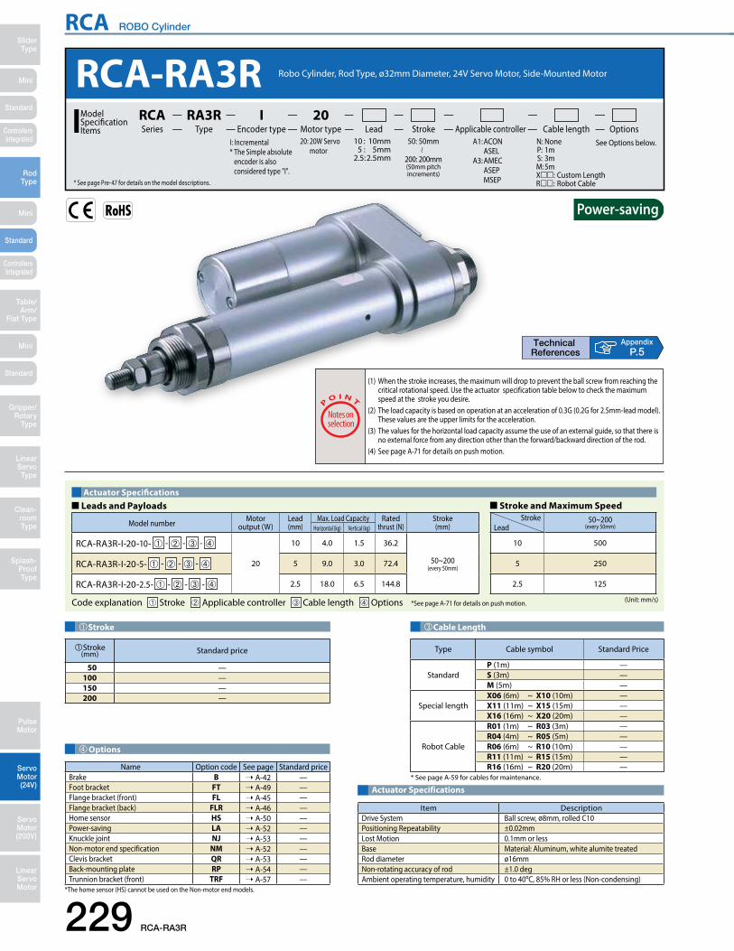
RCA ROBO Cylinder
Mini
Mini
Mini
SliderType
RodType
Table/Arm/
Flat Type
Linear ServoType
Gripper/Rotary
Type
Clean-room Type
Splash-ProofType
Pulse Motor
Servo Motor (24V)
Servo Motor (200V)
LinearServo Motor
Standard
Standard
Standard
ControllersIntegrated
ControllersIntegrated
229 RCA-RA3R
AppendixP.5
Actuator Specifications
Item DescriptionDrive System Ball screw, ø8mm, rolled C10Positioning Repeatability ±0.02mmLost Motion 0.1mm or lessBase Material: Aluminum, white alumite treatedRod diameter ø16mmNon-rotating accuracy of rod ±1.0 degAmbient operating temperature, humidity 0 to 40oC, 85% RH or less (Non-condensing)
Stroke
Stroke (mm) Standard price
50 —100 —150 —200 —
� Leads and Payloads � Stroke and Maximum SpeedActuator Specifications
(Unit: mm/s)
Model number Motor output (W)
Lead(mm)
Max. Load Capacity Ratedthrust (N)
Stroke(mm)Horizontal (kg) Vertical (kg)
RCA-RA3R-I-20-10- ➀ - ➁ - ➂ - ➃
20
10 4.0 1.5 36.2
50~200(every 50mm)RCA-RA3R-I-20-5- ➀ - ➁ - ➂ - ➃ 5 9.0 3.0 72.4
RCA-RA3R-I-20-2.5- ➀ - ➁ - ➂ - ➃ 2.5 18.0 6.5 144.8
Code explanation ➀ Stroke ➁ Applicable controller ➂ Cable length ➃ Options *See page A-71 for details on push motion.
Stroke 50~200(every 50mm)Lead
10 500
5 250
2.5 125
Cable Length
Type Cable symbol Standard Price
StandardP (1m) —S (3m) —M (5m) —
Special lengthX06 (6m) ~ X10 (10m) —X11 (11m) ~ X15 (15m) —X16 (16m) ~ X20 (20m) —
Robot Cable
R01 (1m) ~ R03 (3m) —R04 (4m) ~ R05 (5m) —R06 (6m) ~ R10 (10m) —R11 (11m) ~ R15 (15m) —R16 (16m) ~ R20 (20m) —
* See page A-59 for cables for maintenance.
RCA-RA3R Robo Cylinder, Rod Type, ø32mm Diameter, 24V Servo Motor, Side-Mounted Motor
20: 20W Servo motor
Lead Stroke Cable length OptionsTypeRA3R
Encoder typeI
Motor type20
Applicable controllerSeriesRCAModel
SpecificationItems
50: 50mm
200: 200mm(50mm pitch increments)
* See page Pre-47 for details on the model descriptions.
A1: ACON ASEL A3: AMEC ASEP MSEP
I: Incremental* The Simple absolute
encoder is also considered type "I".
N: None P: 1m S: 3m M: 5mX: Custom Length R: Robot Cable
See Options below. 10 : 10mm 5 : 5mm 2.5 : 2.5mm
(1) When the stroke increases, the maximum will drop to prevent the ball screw from reaching the critical rotational speed. Use the actuator specification table below to check the maximum speed at the stroke you desire.
(2) The load capacity is based on operation at an acceleration of 0.3G (0.2G for 2.5mm-lead model). These values are the upper limits for the acceleration.
(3) The values for the horizontal load capacity assume the use of an external guide, so that there is no external force from any direction other than the forward/backward direction of the rod.
(4) See page A-71 for details on push motion.
Options
*The home sensor (HS) cannot be used on the Non-motor end models.
Name Option code See page Standard priceBrake B ➝ A-42 —Foot bracket FT ➝ A-49 —Flange bracket (front) FL ➝ A-45 —Flange bracket (back) FLR ➝ A-46 —Home sensor HS ➝ A-50 —Power-saving LA ➝ A-52 —Knuckle joint NJ ➝ A-53 —Non-motor end specification NM ➝ A-52 —Clevis bracket QR ➝ A-53 —Back-mounting plate RP ➝ A-54 —Trunnion bracket (front) TRF ➝ A-57 —

RCA ROBO Cylinder
Mini
Mini
Mini
SliderType
RodType
Table/Arm/Flat Type
Linear ServoType
Gripper/Rotary Type
Clean-room Type
Splash-ProofType
Pulse Motor
Servo Motor (24V)
Servo Motor (200V)
LinearServo Motor
Standard
Standard
Standard
ControllersIntegrated
ControllersIntegrated
CAD drawings can be downloaded from the website. www.intelligentactuator.com
RCA-RA3R 230
Dimensional Drawings
ø42
ø16
(rod
OD
)
M8 depth 15
32 (width across flats) *3
14 (width across flats) *3
3 3
181818
84.4
42.4
84.4
42.4
31
L
st ℓ
ℓ
49
8 10
P
2585.5
ø32
ø35
(15
.01
)
135
ø34
7 32
M26×1.5(effective screw thread range 15.5)
Nut A
Nut A
M26x1.5
M8×1.25
M8×1.25(effective screw thread range 16)
Nut B
ME *2HomeME
SE
M26×1.5(effective screw thread range 15.5)
Sec
ure
at le
ast
100
ø42
ø16
(rod
OD
)
32 (width across flats)
14 (width across flats)
3 3
31st
L
49
8 10
P
25124.5
43ø
32ø
35 Nut A
Nut A
Nut B
ME *2HomeME
SE
[Brake-Equipped]
[No Brake]
Dimensions of Nut A Dimensions of Nut B
Cable jointconnector *1
AppendixP.15
Do not apply any external force on the rod from any direction other than the direction of the rod's motion. If a force is exerted on the rod in a perpendicular or rotational direction, the detent may become damaged.
Note:
(*1) Connect the motor and encoder cables here. See page A-59 for details on cables.(*2) After homing, the slider moves to the ME, therefore, please watch for any interference with surrounding objects. ME : Mechanical end SE : Stroke end(*3) The orientation of the bolt varies depending on the product.
2D CAD2D
CAD
Stroke 50 100 150 200L 218 268 318 368ℓ 120 170 220 270P 116.5
Weight (kg) 0.8 0.9 1.0 1.1
�Dimensions and Weight by StrokeRCA-RA3R (without brake)
Stroke 50 100 150 200L 218 268 318 368ℓ 120 170 220 270P 155.5
Weight (kg) 1.0 1.1 1.2 1.3
RCA-RA3R (with brake)
RCA series actuators can be operated with the controllers indicated below. Select the type according to your intended application. * ACON-CY also can be used.Applicable Controllers
Name Externalview Model number Features Maximum number of
positioning pointsInputpower
Power-supply capacity
Standardprice
Reference page
Solenoid Valve Type
AMEC-C-20SI - -2-1 Easy-to-use controller, even for beginners
3 points
AC100V 2.4A rated — ➝ P537
ASEP-C-20SI - -2-0 Simple controller operable with the same signal as a solenoid valve
DC24V
(Standard)1.7A rated5.1A max.
(Power-saving)1.7A rated3.4A max.
— ➝ P547
Solenoid valve multi-axis type PIO specification MSEP-C- -~- -2-0 Positioner type based on PIO control,
allowing up to 8 axes to be connected— ➝ P563
Solenoid valve multi-axis type Network specification MSEP-C- -~- -0-0 Field network-ready positioner type,
allowing up to 8 axes to be connected 256 points
Positioner type ACON-C-20SI - -2-0Positioning is possible for up to 512 points 512 points
—
➝ P631
Safety-Compliant Positioner Type ACON-CG-20SI - -2-0 —
Pulse Train Input Type (Differential Line Driver) ACON-PL-20SI - -2-0 Pulse train input type with
differential line driver support(—)
—
Pulse Train Input Type (Open Collector) ACON-PO-20SI - -2-0 Pulse train input type with open
collector support —
Serial Communication Type ACON-SE-20SI -N-0-0 Dedicated Serial Communication 64 points —
Program Control Type ASEL-CS-1-20SI - -2-0 Programmed operation is possible.
Can operate up to 2 axes 1,500 points — ➝ P675
* This is for the single-axis ASEL. * Enter the code "LA" in when the power-saving specification is specified. * indicates I/O type (NP/PN).* indicates number of axes (1 to 8). * indicates field network specification symbol.

RCA ROBO Cylinder
Mini
Mini
Mini
SliderType
RodType
Table/Arm/
Flat Type
Linear ServoType
Gripper/Rotary
Type
Clean-room Type
Splash-ProofType
Pulse Motor
Servo Motor (24V)
Servo Motor (200V)
LinearServo Motor
Standard
Standard
Standard
ControllersIntegrated
ControllersIntegrated
231 RCA-RA4R
AppendixP.5
RCA-RA4R Robo Cylinder, Rod Type, ø37mm Diameter, 24V Servo Motor, Side-Mounted Motor
20: 20W Servo motor 30: 30W Servo motor
Lead Stroke Cable length OptionsTypeRA4R
Encoder type Motor type Applicable controllerSeriesRCAModel
SpecificationItems
50: 50mm
300: 300mm(50mm pitch increments)
* See page Pre-47 for details on the model descriptions.
A1: ACON ASEL A3: AMEC ASEP MSEP
I : IncrementalA: Absolute* The absolute models are only compatible with ASEL. Simple absolute encoders are considered incremental.
N: None P: 1m S: 3m M: 5mX: Custom Length R: Robot Cable
See Options below. 12 : 12mm 6 : 6mm 3 : 3mm
(1) When the stroke increases, the maximum will drop to prevent the ball screw from reaching the critical rotational speed. Use the actuator specification table below to check the maximum speed at the stroke you desire.
(2) The load capacity is based on operation at an acceleration of 0.3G (0.2G for 3mm-lead model). These values are the upper limits for the acceleration.
(3) The values for the horizontal load capacity assume the use of an external guide, so that there is no external force from any direction other than the forward/backward direction of the rod.
(4) See page A-71 for details on push motion.
� Leads and Payloads � Stroke and Maximum SpeedActuator Specifications
(Unit: mm/s)
Code explanation ➀ Encoder ➁ Stroke ➂ Applicable controller ➃ Cable length ➄ Options *See page A-71 for details on push motion.
Model number Motor output (W)
Lead(mm)
Max. Load Capacity Ratedthrust (N)
Stroke(mm)Horizontal (kg) Vertical (kg)
RCA-RA4R- ➀ -20-12- ➁ - ➂ - ➃ - ➄
20
12 3.0 1.0 18.9
50~300(every 50mm)
RCA-RA4R- ➀ -20-6- ➁ - ➂ - ➃ - ➄ 6 6.0 2.0 37.7
RCA-RA4R- ➀ -20-3- ➁ - ➂ - ➃ - ➄ 3 12.0 4.0 75.4
RCA-RA4R- ➀ -30-12- ➁ - ➂ - ➃ - ➄
30
12 4.0 1.5 28.3
RCA-RA4R- ➀ -30-6- ➁ - ➂ - ➃ - ➄ 6 9.0 3.0 56.6
RCA-RA4R- ➀ -30-3- ➁ - ➂ - ➃ - ➄ 3 18.0 6.5 113.1
Stroke 50~300(every 50mm)Lead
12 600
6 300
3 150
Cable Length
Type Cable symbol Standard Price
StandardP (1m) —S (3m) —M (5m) —
Special lengthX06 (6m) ~ X10 (10m) —X11 (11m) ~ X15 (15m) —X16 (16m) ~ X20 (20m) —
Robot Cable
R01 (1m) ~ R03 (3m) —R04 (4m) ~ R05 (5m) —R06 (6m) ~ R10 (10m) —R11 (11m) ~ R15 (15m) —R16 (16m) ~ R20 (20m) —
* See page A-59 for cables for maintenance.
Actuator Specifications
Item DescriptionDrive System Ball screw, ø10mm, rolled C10Positioning Repeatability ±0.02mmLost Motion 0.1mm or lessBase Material: Aluminum, white alumite treatedRod diameter ø20mmNon-rotating accuracy of rod ±1.0 degAmbient operating temperature, humidity 0 to 40oC, 85% RH or less (Non-condensing)
Encoder Type/Stroke
➁Stroke (mm)
Standard priceEncoder Type
Incremental AbsoluteMotor Output (W) Motor Output (W)
20W 30W 20W 30W50 — — — —
100 — — — —150 — — — —200 — — — —250 — — — —300 — — — —
Options
*The home sensor (HS) cannot be used on the Non-motor end models.
Name Option code See page Standard priceBrake B ➝ A-42 —Foot bracket FT ➝ A-49 —Flange bracket (front) FL ➝ A-45 —Flange bracket (back) FLR ➝ A-46 —Home sensor HS ➝ A-50 —Power-saving LA ➝ A-52 —Knuckle joint NJ ➝ A-53 —Non-motor end specification NM ➝ A-52 —Clevis bracket QR ➝ A-53 —Back-mounting plate RP ➝ A-54 —Trunnion bracket (front) TRF ➝ A-57 —

RCA ROBO Cylinder
Mini
Mini
Mini
SliderType
RodType
Table/Arm/Flat Type
Linear ServoType
Gripper/Rotary Type
Clean-room Type
Splash-ProofType
Pulse Motor
Servo Motor (24V)
Servo Motor (200V)
LinearServo Motor
Standard
Standard
Standard
ControllersIntegrated
ControllersIntegrated
CAD drawings can be downloaded from the website. www.intelligentactuator.com
RCA-RA4R 232
Dimensional Drawings
ø37
48
Incr
emen
tal ø
42Ab
solu
te ø
48
ø50
ø20
(ro
d O
D)
Pm
M10×1.25depth 18
50.5
98.5
50.5
98.5
3 3
19 (width across flats)*3
36 (width across flats) *3
L
33ℓ
ℓ
56
9 10
26
20 2022(1
9.6)
17
ø40.2
38
M10x1.25
8
M30×1. 5
6
M30×1.5(effective screw thread range 17.5)
Nut A
st
HomeSEME ME*2
M30×1.5(effective screw thread range 17.5)
Nut B
Nut A
Cable jointconnector *1
M10×1.25(effective screw thread range 20)
Sec
ure
at le
ast
100
ø37
Incr
emen
tal ø
42Ab
solu
te ø
48 ø50
ø20
(ro
d O
D)
Pm
3 3
19 (width across flats) 36 (width across flats)
L
3356
9 10
26
47
Nut A
st
HomeSEME ME
Nut B
Nut A
Nut A Nut B
[Brake-Equipped]
[No Brake]
AppendixP.15
Stroke 50 100 150 200 250 300
L20W Increm. 234 284 334 384 434 484
Absol. 234 284 334 384 434 484
30W Increm. 234 284 334 384 434 484Absol. 234 284 334 384 434 484
ℓ 125 175 225 275 325 375
m20W Increm. 67.5
Absol. 80.5
30W Increm. 82.5Absol. 95.5
P20W Increm. 100.5
Absol. 113.5
30W Increm. 115.5Absol. 128.5
Weight (kg) 1.2 1.4 1.5 1.7 1.8 2.0
�Dimensions and Weight by StrokeRCA-RA4R (without brake)
Stroke 50 100 150 200 250 300
L20W Increm. 234 284 334 384 434 484
Absol. 234 284 334 384 434 484
30W Increm. 234 284 334 384 434 484Absol. 234 284 334 384 434 484
ℓ 125 175 225 275 325 375
m20W Increm. 110.5
Absol. 123.5
30W Increm. 125.5Absol. 138.5
P20W Increm. 143.5
Absol. 156.5
30W Increm. 158.5Absol. 171.5
Weight (kg) 1.4 1.6 1.7 1.9 2.0 2.2
RCA-RA4R (with brake)
Do not apply any external force on the rod from any direction other than the direction of the rod's motion. If a force is exerted on the rod in a perpendicular or rotational direction, the detent may become damaged.
Note:
(*1) Connect the motor and encoder cables here. See page A-59 for details on cables.(*2) After homing, the slider moves to the ME, therefore, please watch for any interference with surrounding objects. ME : Mechanical end SE : Stroke end(*3) The orientation of the bolt varies depending on the product.
2D CAD2D
CAD
RCA series actuators can be operated with the controllers indicated below. Select the type according to your intended application. * ACON-CY also can be used.Applicable Controllers
Name Externalview Model number Features Maximum number of
positioning pointsInputpower
Power-supply capacity
Standardprice
Reference page
Solenoid Valve Type
AMEC-C-20I - -2-1AMEC-C-30I - -2-1
Easy-to-use controller, even for beginners
3 points
AC100V 2.4A rated — ➝ P537
ASEP-C-20I - -2-0ASEP-C-30I - -2-0
Simple controller operable with the same signal as a solenoid valve
DC24V
(Standard)20W
1.3A rated4.4A max.
30W1.3A rated4.4A max.
(Power-saving)20W
1.3A rated2.5A max.
30W1.3A rated2.2A max.
— ➝ P547
Solenoid valve multi-axis type PIO specification MSEP-C- -~- -2-0 Positioner type based on PIO control,
allowing up to 8 axes to be connected— ➝ P563
Solenoid valve multi-axis type Network specification MSEP-C- -~- -0-0 Field network-ready positioner type,
allowing up to 8 axes to be connected 256 points
Positioner type ACON-C-20I - -2-0ACON-C-30I - -2-0 Positioning is possible for up to 512
points 512 points
—
➝ P631
Safety-Compliant Positioner Type
ACON-CG-20I - -2-0ACON-CG-30I - -2-0 —
Pulse Train Input Type (Differential Line Driver)
ACON-PL-20I - -2-0ACON-PL-30I - -2-0
Pulse train input type with differential line driver support
(—)
—
Pulse Train Input Type (Open Collector)
ACON-PO-20I - -2-0ACON-PO-30I - -2-0
Pulse train input type with open collector support —
Serial Communication Type ACON-SE-20I -N-0-0ACON-SE-30I -N-0-0 Dedicated Serial Communication 64 points —
Program Control Type
ASEL-CS-1-20 - -2-0ASEL-CS-1-30 - -2-0
Programmed operation is possible. Can operate up to 2 axes 1,500 points — ➝ P675
* This is for the single-axis ASEL. * indicates encoder type (I: incremental, A: absolute) * Enter the code "LA" in when the power-saving specification is specified.* indicates I/O type (NP/PN). * indicates number of axes (1 to 8). * indicates field network specification symbol.

RCA ROBO Cylinder
Mini
Mini
Mini
SliderType
RodType
Table/Arm/
Flat Type
Linear ServoType
Gripper/Rotary
Type
Clean-room Type
Splash-ProofType
Pulse Motor
Servo Motor (24V)
Servo Motor (200V)
LinearServo Motor
Standard
Standard
Standard
ControllersIntegrated
ControllersIntegrated
233 RCA-SRA4R
Stroke
AppendixP.5
Actuator Specifications
Item DescriptionDrive System Ball screw, ø8mm, rolled C10Positioning Repeatability ±0.02mmLost Motion 0.1mm or lessRod diameter ø22mmNon-rotating accuracy of rod —Ambient operating temperature, humidity 0 to 40oC, 85% RH or less (Non-condensing)
Stroke(mm) Standard price
20~50 —60~100 —
150 —200 —
Cable Length
Type Cable symbol Standard Price
Standard(Robot Cables)
P (1m) —S (3m) —M (5m) —
Special lengthX06 (6m) ~ X10 (10m) —X11 (11m) ~ X15 (15m) —X16 (16m) ~ X20 (20m) —
* The cable is a motor-encoder integrated cable, and is provided as a robot cable.* See page A-59 for cables for maintenance.
(1) The load capacity is based on operation at an acceleration of 0.3G (0.2G for the 2.5mm-lead model, or when used vertically). This is the upper limit of the acceleration.
(2) The horizontal load capacity is based on the use of an external guide. If an external force is exerted on the rod from a direction other than the motion of the rod, the detent may become damaged.
(3) See page A-71 for details on push motion.
Options
* The brake is available for strokes of 70mm or more.
Name Option code See page Standard priceBrake B ➝ A-42 —Flange bracket (front) FL ➝ A-44 —Flange bracket (back) FLR ➝ A-46 —Foot bracket 1 (base mounting) FT ➝ A-48 —Foot bracket 2 (right/left side mounting) FT2/FT4 ➝ A-50 —Power-saving LA ➝ A-52 —Non-motor end specification NM ➝ A-52 —
RCA-SRA4R20: 20W Servo motor
Lead Stroke Cable length OptionsTypeSRA4R
Encoder typeI
Motor type20
Applicable controllerSeriesRCAModel
SpecificationItems
20: 20mm
200: 200mm(10mm pitch increments)* Set in 50mm increments over 100mm* See page Pre-47 for details on the model descriptions.
A1: ACON ASEL A3: AMEC ASEP MSEP
I: Incremental* The Simple absolute
encoder is also considered type "I".
N: None P: 1m S: 3m M: 5mX: Custom Length
See Options below. 5 : 5mm 2.5 : 2.5mm
Robo Cylinder, Rod Type, Actuator Width 45mm, Servo Motor, Short-Length Type
� Leads and Payloads � Stroke and Maximum SpeedActuator Specifications
(Unit: mm/s)
Model number Motor output (W)
Lead(mm)
Max. Load Capacity Ratedthrust (N)
Stroke(mm)Horizontal (kg) Vertical (kg)
RCA-SRA4R-I-20-5- ➀ - ➁ - ➂ - ➃20
5 9 (Note1) 3 41 20~200(every 10mm)
(Note A)RCA-SRA4R-I-20-2.5- ➀ - ➁ - ➂ - ➃ 2.5 18 (Note1) 6.5 81
Code explanation ➀ Stroke ➁ Applicable controller ➂ Cable length ➃ Options *See page A-71 for details on push motion.
Stroke 20~200(every 10mm)Lead
5 250
2.5 125
(Note A) 50mm increments over 100mm.

RCA ROBO Cylinder
Mini
Mini
Mini
SliderType
RodType
Table/Arm/Flat Type
Linear ServoType
Gripper/Rotary Type
Clean-room Type
Splash-ProofType
Pulse Motor
Servo Motor (24V)
Servo Motor (200V)
LinearServo Motor
Standard
Standard
Standard
ControllersIntegrated
ControllersIntegrated
Dimensional Drawings
RCA-SRA4R 234
6
Dimensions of the Supplied Nut
M10×1.25
(19.
6)
17
4-M6 depth 12
34
34
M10×1.25
ø22
ø32
7.5 (width across flats)22
31.5 4.8 4.2
4-M6 depth 12
Cable jointconnector (*1)
width across flats (*3)
4534
9550
45 34 14
14
22.5
(210
)
Sec
ure
at le
ast
100
E-M4 depth 10
348D×50C24
ME SE ME (*2)Home
E-M4 depth 10(same with opposite side)
34
C D×50 1517
LA
22B40.5
3
st
3
ST : StrokeSE : Stroke endME : Mechanical end
CAD drawings can be downloaded from the website. www.intelligentactuator.com Appendix
P.15
Do not apply any external force on the rod from any direction other than the direction of the rod's motion. If a force is exerted on the rod in a perpendicular or rotational direction, the detent may become damaged.
Note:
* This is for the single-axis ASEL. * Enter the code "LA" in when the power-saving specification is specified. * indicates I/O type (NP/PN).* indicates number of axes (1 to 8). * indicates field network specification symbol.
RCA series actuators can be operated with the controllers indicated below. Select the type according to your intended application. * ACON-CY also can be used.Applicable Controllers
Name Externalview Model number Features Maximum number of
positioning pointsInputpower
Power-supply capacity
Standardprice
Reference page
Solenoid Valve Type
AMEC-C-20I - -2-1 Easy-to-use controller, even for beginners
3 points
AC100V 2.4A rated — ➝ P537
ASEP-C-20I - -2-0 Simple controller operable with the same signal as a solenoid valve
DC24V
(Standard)1.3A rated4.4A max.
(Power-saving)1.3A rated2.5A max.
— ➝ P547
Solenoid valve multi-axis type PIO specification MSEP-C- -~- -2-0 Positioner type based on PIO control,
allowing up to 8 axes to be connected— ➝ P563
Solenoid valve multi-axis type Network specification MSEP-C- -~- -0-0 Field network-ready positioner type,
allowing up to 8 axes to be connected 256 points
Positioner type ACON-C-20I - -2-0Positioning is possible for up to 512 points 512 points
—
➝ P631
Safety-Compliant Positioner Type ACON-CG-20I - -2-0 —
Pulse Train Input Type (Differential Line Driver) ACON-PL-20I - -2-0 Pulse train input type with
differential line driver support(—)
—
Pulse Train Input Type (Open Collector) ACON-PO-20I - -2-0 Pulse train input type with open
collector support —
Serial Communication Type ACON-SE-20I -N-0-0 Dedicated Serial Communication 64 points —
Program Control Type ASEL-CS-1-20I - -2-0 Programmed operation is possible.
Can operate up to 2 axes 1,500 points — ➝ P675
(*1) Connect the motor-encoder integrated cable here. See page A-59 for details on cables.(*2) After homing, the slider moves to the ME, therefore, please watch for any interference with surrounding objects.(*3) The orientation of the bolt varies depending on the product.
* The exterior dimensions for the brake-equipped model is no different than the standard model. However, 70mm is the minimum stroke of the brake-equipped models. (i.e. The brake is not compatible at 60mm strokes and under.)
2D CAD2D
CAD
Stroke 20 30 40 50 60 70 80 90 100 150 200L 124.5 134.5 144.5 154.5 164.5 174.5 184.5 194.5 204.5 254.5 304.5 A 84 94 104 114 124 134 144 154 164 214 264 B 62 72 82 92 102 112 122 132 142 192 242C 30 40 50 60 70 30 40 50 60 60 60D 0 0 0 0 0 1 1 1 1 2 3E 4 4 4 4 4 6 6 6 6 8 10
Weight (kg) 0.78 0.84 0.9 0.96 1.03 1.09 1.15 1.21 1.27 1.59 1.9
�Dimensions and Weight by Stroke (Add 0.2kg for brake equipped)

RCA ROBO Cylinder
Mini
Mini
Mini
SliderType
RodType
Table/Arm/
Flat Type
Linear ServoType
Gripper/Rotary
Type
Clean-room Type
Splash-ProofType
Pulse Motor
Servo Motor (24V)
Servo Motor (200V)
LinearServo Motor
Standard
Standard
Standard
ControllersIntegrated
ControllersIntegrated
235 RCA-RGS3C
AppendixP.5
Actuator Specifications
Item DescriptionDrive System Ball screw, ø8mm, rolled C10Positioning Repeatability ±0.02mmLost Motion 0.1mm or lessGuide Single guide (guide rod diameter ø8mm, Ball bush type)Rod diameter ø16mmNon-rotating accuracy of rod ±0.05 degAmbient operating temperature, humidity 0 to 40oC, 85% RH or less (Non-condensing)
Stroke
Stroke (mm) Standard price
50 —100 —150 —200 —
� Leads and Payloads � Stroke and Maximum SpeedActuator Specifications
(Unit: mm/s)
Model number Motor output (W)
Lead(mm)
Max. Load Capacity Ratedthrust (N)
Stroke(mm)Horizontal (kg) Vertical (kg)
RCA-RGS3C-I-20-10- ➀ - ➁ - ➂ - ➃
20
10 4.0 1.2 36.2
50~200(every 50mm)RCA-RGS3C-I-20-5- ➀ - ➁ - ➂ - ➃ 5 9.0 2.7 72.4
RCA-RGS3C-I-20-2.5- ➀ - ➁ - ➂ - ➃ 2.5 18.0 6.2 144.8
Code explanation ➀ Stroke ➁ Applicable controller ➂ Cable length ➃ Options *See page A-71 for details on push motion.
Stroke 50~200(every 50mm)Lead
10 500
5 250
2.5 125
Cable Length
Type Cable symbol Standard Price
StandardP (1m) —S (3m) —M (5m) —
Special lengthX06 (6m) ~ X10 (10m) —X11 (11m) ~ X15 (15m) —X16 (16m) ~ X20 (20m) —
Robot Cable
R01 (1m) ~ R03 (3m) —R04 (4m) ~ R05 (5m) —R06 (6m) ~ R10 (10m) —R11 (11m) ~ R15 (15m) —R16 (16m) ~ R20 (20m) —
* See page A-59 for cables for maintenance.
RCA-RGS3C Robo Cylinder, Rod Type with Single Guide, ø32mm Diameter, 24V Servo Motor, Coupled
20: 20W Servo motor
Lead Stroke Cable length OptionsTypeRGS3C
Encoder typeI
Motor type20
Applicable controllerSeriesRCAModel
SpecificationItems
50: 50mm
200: 200mm(50mm pitch increments)
* See page Pre-47 for details on the model descriptions.
A1: ACON ASEL A3: AMEC ASEP MSEP
I: Incremental* The Simple absolute
encoder is also considered type "I".
N: None P: 1m S: 3m M: 5mX: Custom LengthR: Robot Cable
See Options below. 10 : 10mm 5 : 5mm 2.5 : 2.5mm
(1) When the stroke increases, the maximum speed will drop to prevent the ball screw from reaching the critical rotational speed. Use the actuator specification table below to check the maximum speed at the stroke you desire.
(2) The load capacity is based on operating the standard and power-saving models at 0.3G (0.2G for 2.5mm-lead), and 1G acceleration for the high-acceleration models (2.5mm-lead model excluded). The values in the table below are the upper limits, even if the acceleration/deceleration is decreased.
(3) The values for the horizontal load capacity reflect the use of an external guide. See the technical resources (page A-110) for the allowable weight using the supplied guide alone.
(4) See page A-71 for details on push motion.
Options
Name Option code See page Standard priceBrake B ➝ A-42 —Foot bracket FT ➝ A-49 —High-acceleration/deceleration (*1) HA ➝ A-50 —Home sensor (*2) HS ➝ A-50 —Power-saving (*3) LA ➝ A-52 —Non-motor end specification NM ➝ A-52 —Trunnion bracket (back) TRR ➝ A-58 —
(*1) The high-acceleration/deceleration option is not available for 2.5mm-lead model.(*2) The home sensor (HS) cannot be used on the non-motor end models.(*3) The high-acceleration/deceleration option and the power-saving option cannot be used simultaneously.
(excluding the 2.5mm-lead model)

RCA ROBO Cylinder
Mini
Mini
Mini
SliderType
RodType
Table/Arm/Flat Type
Linear ServoType
Gripper/Rotary Type
Clean-room Type
Splash-ProofType
Pulse Motor
Servo Motor (24V)
Servo Motor (200V)
LinearServo Motor
Standard
Standard
Standard
ControllersIntegrated
ControllersIntegrated
Dimensional Drawings
RCA-RGS3C 236
CAD drawings can be downloaded from the website. www.intelligentactuator.com
Cable jointconnector *1
462415
37.5
7052
.530
.5
14
4-C2
8 85.517L
5(st+12)53
Shaft overhang at SE
MEHome
(st+65)
12 st 3
35st
33
20
ø8 (g
uide
rod
OD
)
4-M5
8
41.5
19.5
702415
30.5
3729
Bracket B
Bracket A
12
4-C2
1020
.510 52
.530
.5
30
20
37
70
4646
6-M4 through-hole
ø16
(rod
OD
)
14 (width across flats)
40 (width across flats)32 (width across flats)
ø35
ø42
ø32
Nut BNut A
ME*2HomeME SE
M35×1.5(effective screw thread range 17.5)
M26x1.5M35x1.5
8
ø34
4632
ø48.6
7
14 43
8 ℓ
ℓ
124.517L
5(st+12)53
Bracket B
Bracket A14 (width across flats)
40 (width across flats)32 (width across flats)
ø35
ø42
ø32
Nut BNut A
Secu
re a
t lea
st 1
00
Nut A
Bracket BBracket A
Nut B
[Brake-Equipped]
[No Brake]
AppendixP.15
(*1) Connect the motor and encoder cables here. See page A-59 for details on cables.(*2) After homing, the slider moves to the ME, therefore, please watch for any interference with surrounding objects. ME : Mechanical end SE : Stroke end
2D CAD2D
CAD
Stroke 50 100 150 200L 277.5 327.5 377.5 427.5ℓ 140 190 240 290
Weight (kg) 0.9 1.1 1.2 1.3
Stroke 50 100 150 200L 316.5 366.5 416.5 466.5ℓ 140 190 240 290
Weight (kg) 1.1 1.3 1.4 1.5
�Dimensions and Weight by StrokeRCA-RGS3C (without brake)
RCA-RGS3C (with brake)
RCA series actuators can be operated with the controllers indicated below. Select the type according to your intended application. * ACON-CY also can be used.Applicable Controllers
Name Externalview Model number Features Maximum number of
positioning pointsInputpower
Power-supply capacity
Standardprice
Reference page
Solenoid Valve Type
AMEC-C-20SI - -2-1 Easy-to-use controller, even for beginners
3 points
AC100V 2.4A rated — ➝ P537
ASEP-C-20SI - -2-0 Simple controller operable with the same signal as a solenoid valve
DC24V
(Standard)1.7A rated5.1A max.
(Power-saving)1.7A rated3.4A max.
— ➝ P547
Solenoid valve multi-axis type PIO specification MSEP-C- -~- -2-0 Positioner type based on PIO control,
allowing up to 8 axes to be connected— ➝ P563
Solenoid valve multi-axis type Network specification MSEP-C- -~- -0-0 Field network-ready positioner type,
allowing up to 8 axes to be connected 256 points
Positioner type ACON-C-20SI - -2-0Positioning is possible for up to 512 points 512 points
—
➝ P631
Safety-Compliant Positioner Type ACON-CG-20SI - -2-0 —
Pulse Train Input Type (Differential Line Driver) ACON-PL-20SI - -2-0 Pulse train input type with
differential line driver support(—)
—
Pulse Train Input Type (Open Collector) ACON-PO-20SI - -2-0 Pulse train input type with open
collector support —
Serial Communication Type ACON-SE-20SI -N-0-0 Dedicated Serial Communication 64 points —
Program Control Type ASEL-CS-1-20SI - -2-0 Programmed operation is possible.
Can operate up to 2 axes 1,500 points — ➝ P675
* This is for the single-axis ASEL. * Enter the code "HA" or "LA" in when the high-acceleration/deceleration option or the power-saving option is specified. * indicates I/O type (NP/PN). * indicates number of axes (1 to 8). * indicates field network specification symbol.

RCA ROBO Cylinder
Mini
Mini
Mini
SliderType
RodType
Table/Arm/
Flat Type
Linear ServoType
Gripper/Rotary
Type
Clean-room Type
Splash-ProofType
Pulse Motor
Servo Motor (24V)
Servo Motor (200V)
LinearServo Motor
Standard
Standard
Standard
ControllersIntegrated
ControllersIntegrated
237 RCA-RGS4C
AppendixP.5
RCA-RGS4C Robo Cylinder, Rod Type with Single Guide, ø37mm Diameter, 24V Servo Motor, Coupled
20: 20W Servo motor 30: 30W Servo motor
Lead Stroke Cable length OptionsTypeRGS4C
Encoder type Motor type Applicable controllerSeriesRCAModel
SpecificationItems
50: 50mm
300: 300mm(50mm pitch increments)
* See page Pre-47 for details on the model descriptions.
A1: ACON ASEL A3: AMEC ASEP MSEP
I: IncrementalA: Absolute* Absolute encoder models can only use ASEL. When the actuator is used with the simple absolute encoder, the model is considered an incremental model.
N: None P: 1m S: 3m M: 5mX: Custom Length R: Robot Cable
See Options below. 12 : 12mm 6 : 6mm 3 : 3mm
� Leads and Payloads � Stroke and Maximum SpeedActuator Specifications
(Unit: mm/s)
Code explanation ➀ Encoder ➁ Stroke ➂ Applicable controller ➃ Cable length ➄ Options *See page A-71 for details on push motion.
Model number Motor output (W)
Lead(mm)
Max. Load Capacity Ratedthrust (N)
Stroke(mm)Horizontal (kg) Vertical (kg)
RCA-RGS4C- ➀ -20-12- ➁ - ➂ - ➃ - ➄
20
12 3.0 0.5 18.9
50~300(every 50mm)
RCA-RGS4C- ➀ -20-6- ➁ - ➂ - ➃ - ➄ 6 6.0 1.5 37.7
RCA-RGS4C- ➀ -20-3- ➁ - ➂ - ➃ - ➄ 3 12.0 3.5 75.4
RCA-RGS4C- ➀ -30-12- ➁ - ➂ - ➃ - ➄
30
12 4.0 1.0 28.3
RCA-RGS4C- ➀ -30-6- ➁ - ➂ - ➃ - ➄ 6 9.0 2.5 56.6
RCA-RGS4C- ➀ -30-3- ➁ - ➂ - ➃ - ➄ 3 18.0 6.0 113.1
Stroke 50~300(every 50mm)Lead
12 600
6 300
3 150
Cable Length
Type Cable symbol Standard Price
StandardP (1m) —S (3m) —M (5m) —
Special lengthX06 (6m) ~ X10 (10m) —X11 (11m) ~ X15 (15m) —X16 (16m) ~ X20 (20m) —
Robot Cable
R01 (1m) ~ R03 (3m) —R04 (4m) ~ R05 (5m) —R06 (6m) ~ R10 (10m) —R11 (11m) ~ R15 (15m) —R16 (16m) ~ R20 (20m) —
* See page A-59 for cables for maintenance.
Stroke
➁Stroke (mm)
Standard priceEncoder Type
Incremental AbsoluteMotor Output (W) Motor Output (W)
20W 30W 20W 30W50 — — — —
100 — — — —150 — — — —200 — — — —250 — — — —300 — — — —
(*1) Except all 20W models and 30W 3mm lead models
(1) When the stroke increases, the maximum speed will drop to prevent the ball screw from reaching the critical rotational speed. Use the actuator specification table below to check the maximum speed at the stroke you desire.
(2) The load capacity is based on operating the standard and power-saving models at 0.3G (0.2G for 3mm-lead), and 1G acceleration for the high-acceleration models (3mm-lead model excluded). (The values in the table below are the upper limits, even if the acceleration/deceleration is decreased.)
(3) The values for the horizontal load capacity reflect the use of an external guide. See the technical resources (page A-111) for the allowable weight using the supplied guide alone.
(4) See page A-71 for details on push motion.
Options
Name Option code See page Standard priceBrake B ➝ A-42 —Foot bracket FT ➝ A-49 —High-acceleration/deceleration (*1) HA ➝ A-50 —Home sensor (*2) HS ➝ A-50 —Power-saving (*3) LA ➝ A-52 —Non-motor end specification NM ➝ A-52 —Trunnion bracket (back) TRR ➝ A-58 —
(*1) The high-acceleration/deceleration option is not available for all 20W models and 30W model with 3mm lead.(*2) The home sensor (HS) cannot be used on the non-motor end models.(*3) The high-acceleration/deceleration option and the power-saving option cannot be used simultaneously.
Actuator Specifications
Item DescriptionDrive System Ball screw, ø10mm, rolled C10Positioning Repeatability ±0.02mmLost Motion 0.1mm or lessGuide Single guide (guide rod diameter ø10mm, Ball bush type)Rod diameter ø20mmNon-rotating accuracy of rod ±0.05 degAmbient operating temperature, humidity 0 to 40oC, 85% RH or less (Non-condensing)
(*1)

RCA ROBO Cylinder
Mini
Mini
Mini
SliderType
RodType
Table/Arm/Flat Type
Linear ServoType
Gripper/Rotary Type
Clean-room Type
Splash-ProofType
Pulse Motor
Servo Motor (24V)
Servo Motor (200V)
LinearServo Motor
Standard
Standard
Standard
ControllersIntegrated
ControllersIntegrated
Dimensional Drawings
RCA2-RGS4C 238
ø52.8ø40.2
50388
M40×1.5M30×1.5
10
4-M54-
C2
8
8136.5
26
5022
372915
5915
36.5
4-C2
6-M5 through-hole
302010
1026
.5
Nut A
Bracket BBracket A
Nut B
[Brake-Equipped]
[No Brake]
Cable jointconnector *1
554426
15
81 59 36.5
ø50
50
81
Bracket A
Bracket B
169
47 (width across flats)
36 (width across flats)
19 (width across flats)
Nut A
Nut B
ø37
Lm19ℓ
1
(st+11)63
5030
(st+74)Home
Shaft overhang at SE
ME
3st11
41
ME *2HomeME SE
33
st
M40×1.5(effective screw thread range 19.5)
22
ø10
(gui
de ro
d O
D)
ø20
(ro
d O
D)
Sec
ure
at
leas
t 10
0
(ø50
)
Bracket A
Bracket B
16 479
47 (width across flats)
36 (width across flats)19 (width across flats)
Nut A
Nut B
ø37
Lm19
1
(st+11)63
Incremental ø42Absolute ø48
Incr
emen
tal
ø42
Ab
solu
te
ø48
ℓ
AppendixP.15
Stroke 50 100 150 200 250 300
L20W Increm. 272.5 322.5 372.5 422.5 472.5 522.5
Absol. 285.5 335.5 385.5 435.5 485.5 535.5
30W Increm. 287.5 337.5 387.5 437.5 487.5 537.5Absol. 300.5 350.5 400.5 450.5 500.5 550.5
ℓ 145 195 245 295 345 395
m20W Increm. 67.5
Absol. 80.5
30W Increm. 82.5Absol. 95.5
Weight (kg) 1.5 1.6 1.8 2.0 2.2 2.4
�Dimensions and Weight by StrokeRCA-RGS4C (without brake)
Stroke 50 100 150 200 250 300
L20W Increm. 315.5 365.5 415.5 465.5 515.5 565.5
Absol. 328.5 378.5 428.5 478.5 528.5 578.5
30W Increm. 330.5 380.5 430.5 480.5 530.5 580.5Absol. 343.5 393.5 443.5 493.5 543.5 593.5
ℓ 145 195 245 295 345 395
m20W Increm. 110.5
Absol. 123.5
30W Increm. 125.5Absol. 138.5
Weight (kg) 1.7 1.8 2.0 2.2 2.4 2.6
RCA-RGS4C (with brake)
(*1) Connect the motor and encoder cables here. See page A-59 for details on cables.(*2) After homing, the slider moves to the ME, therefore, please watch for any interference with surrounding objects. ME : Mechanical end SE : Stroke end
2D CAD2D
CAD
CAD drawings can be downloaded from the website. www.intelligentactuator.com
RCA series actuators can be operated with the controllers indicated below. Select the type according to your intended application. * ACON-CY also can be used.Applicable Controllers
Name Externalview Model number Features Maximum number of
positioning pointsInputpower
Power-supply capacity
Standardprice
Reference page
Solenoid Valve Type
AMEC-C-20I - -2-1AMEC-C-30I - -2-1
Easy-to-use controller, even for beginners
3 points
AC100V 2.4A rated — ➝ P537
ASEP-C-20I - -2-0ASEP-C-30I - -2-0
Simple controller operable with the same signal as a solenoid valve
DC24V
(Standard)20W
1.3A rated4.4A max.
30W1.3A rated4.4A max.
(Power-saving)20W
1.3A rated2.5A max.
30W1.3A rated2.2A max.
— ➝ P547
Solenoid valve multi-axis type PIO specification MSEP-C- -~- -2-0 Positioner type based on PIO control,
allowing up to 8 axes to be connected— ➝ P563
Solenoid valve multi-axis type Network specification MSEP-C- -~- -0-0 Field network-ready positioner type,
allowing up to 8 axes to be connected 256 points
Positioner type ACON-C-20I - -2-0ACON-C-30I - -2-0 Positioning is possible for up to 512
points 512 points
—
➝ P631
Safety-Compliant Positioner Type
ACON-CG-20I - -2-0ACON-CG-30I - -2-0 —
Pulse Train Input Type (Differential Line Driver)
ACON-PL-20I - -2-0ACON-PL-30I - -2-0
Pulse train input type with differential line driver support
(—)
—
Pulse Train Input Type (Open Collector)
ACON-PO-20I - -2-0ACON-PO-30I - -2-0
Pulse train input type with open collector support —
Serial Communication Type ACON-SE-20I -N-0-0ACON-SE-30I -N-0-0 Dedicated Serial Communication 64 points —
Program Control Type
ASEL-CS-1-20 - -2-0ASEL-CS-1-30 - -2-0
Programmed operation is possible. Can operate up to 2 axes 1,500 points — ➝ P675
* This is for the single-axis ASEL. * indicates encoder type (I: incremental, A: absolute) * Enter the code "HA" or "LA" in when the high-acceleration/deceleration option or the power-saving option is specified. * indicates I/O type (NP/PN). * indicates number of axes (1 to 8). * indicates field network specification symbol.

RCA ROBO Cylinder
Mini
Mini
Mini
SliderType
RodType
Table/Arm/
Flat Type
Linear ServoType
Gripper/Rotary
Type
Clean-room Type
Splash-ProofType
Pulse Motor
Servo Motor (24V)
Servo Motor (200V)
LinearServo Motor
Standard
Standard
Standard
ControllersIntegrated
ControllersIntegrated
239 RCA-RGS3D
AppendixP.5
Actuator Specifications
Item DescriptionDrive System Ball screw, ø8mm, rolled C10Positioning Repeatability ±0.02mmLost Motion 0.1mm or lessGuide Single guide (guide rod diameter ø8mm, Ball bush type)Rod diameter ø16mmNon-rotating accuracy of rod ±0.05 degAmbient operating temperature, humidity 0 to 40oC, 85% RH or less (Non-condensing)
Stroke
Stroke (mm) Standard price
50 —100 —150 —200 —
� Leads and Payloads � Stroke and Maximum SpeedActuator Specifications
(Unit: mm/s)
Model number Motor output (W)
Lead(mm)
Max. Load Capacity Ratedthrust (N)
Stroke(mm)Horizontal (kg) Vertical (kg)
RCA-RGS3D-I-20-10- ➀ - ➁ - ➂ - ➃
20
10 4.0 1.2 36.2
50~200(every 50mm)RCA-RGS3D-I-20-5- ➀ - ➁ - ➂ - ➃ 5 9.0 2.7 72.4
RCA-RGS3D-I-20-2.5- ➀ - ➁ - ➂ - ➃ 2.5 18.0 6.2 144.8
Code explanation ➀ Stroke ➁ Applicable controller ➂ Cable length ➃ Options *See page A-71 for details on push motion.
Stroke 50~200(every 50mm)Lead
10 500
5 250
2.5 125
Cable Length
Type Cable symbol Standard Price
StandardP (1m) —S (3m) —M (5m) —
Special lengthX06 (6m) ~ X10 (10m) —X11 (11m) ~ X15 (15m) —X16 (16m) ~ X20 (20m) —
Robot Cable
R01 (1m) ~ R03 (3m) —R04 (4m) ~ R05 (5m) —R06 (6m) ~ R10 (10m) —R11 (11m) ~ R15 (15m) —R16 (16m) ~ R20 (20m) —
* See page A-59 for cables for maintenance.
RCA-RGS3D Robo Cylinder, Rod Type with Single Guide, ø32mm Diameter, 24V Servo Motor, Built-In Model
20: 20W Servo motor
Lead Stroke Cable length OptionsTypeRGS3D
Encoder typeI
Motor type20
Applicable controllerSeriesRCAModel
SpecificationItems
50: 50mm
200: 200mm(50mm pitch increments)
* See page Pre-47 for details on the model descriptions.
A1: ACON ASEL A3: AMEC ASEP MSEP
I: Incremental* The Simple absolute
encoder is also considered type "I".
N: None P: 1m S: 3m M: 5mX: Custom Length R: Robot Cable
See Options below. 10 : 10mm 5 : 5mm 2.5 : 2.5mm
(1) When the stroke increases, the maximum speed will drop to prevent the ball screw from reaching the critical rotational speed. Use the actuator specification table below to check the maximum speed at the stroke you desire.
(2) The load capacity is based on operation at an acceleration of 0.3G (0.2G for the 2.5mm-lead model). This is the upper limit of the acceleration.
(3) The values for the horizontal load capacity reflect the use of an external guide. See the technical resources (page A-110) for the allowable weight using the supplied guide alone.
(4) See page A-71 for details on push motion.
Options
Name Option code See page Standard priceFoot bracket FT ➝ A-49 —Home sensor HS ➝ A-50 —Power-saving LA ➝ A-52 —Non-motor end specification NM ➝ A-52 —Trunnion bracket (back) TRR ➝ A-58 —
* The home sensor (HS) cannot be used on the non-motor end models.

RCA ROBO Cylinder
Mini
Mini
Mini
SliderType
RodType
Table/Arm/Flat Type
Linear ServoType
Gripper/Rotary Type
Clean-room Type
Splash-ProofType
Pulse Motor
Servo Motor (24V)
Servo Motor (200V)
LinearServo Motor
Standard
Standard
Standard
ControllersIntegrated
ControllersIntegrated
Dimensional Drawings
RCA-RGS3D 240
CAD drawings can be downloaded from the website. www.intelligentactuator.com
[No Brake]
Cable jointconnector*1
ø35
ø42
4624
1537
.5
70 52.5 30
.5
14
8 ℓ 66.517
L
5(st+12)53
Shaft overhang at SE
MEHome
(st+65)
12 st 3
35st
33
20
ø8 (g
uide
rod
OD
)
Bracket B
Bracket A
37
70
4646
ø16
(rod
OD
)
14 (width across flats)
40 (width across flats)
32 (width across flats)ø3
2
Nut B
Nut A
ME *2HomeME SE
(effective screw thread range 17.5)M35×1.5
4-C24-M5
8
41.5
19.5
70
2415
30.5
37
2912
4-C2
1020
.510 52
.530.5
30
20
6-M4 through-hole
M26x1.5M35x1.5
8
ø34
4632
ø48.6
7
Bracket BBracket A
Nut BNut A
Secu
re a
t le
ast 1
00
AppendixP.15
(*1) Connect the motor and encoder cables here. See page A-59 for details on cables.(*2) After homing, the slider moves to the ME, therefore, please watch for any interference with surrounding objects. ME : Mechanical end SE : Stroke end
2D CAD2D
CAD
Stroke 50 100 150 200L 258.5 308.5 358.5 408.5ℓ 140 190 240 290
Weight (kg) 0.9 1.1 1.2 1.3
�Dimensions and Weight by StrokeRCA-RGS3D (without brake)
RCA-RGS3D models are not equipped with a brake.
RCA series actuators can be operated with the controllers indicated below. Select the type according to your intended application. * ACON-CY also can be used.Applicable Controllers
Name Externalview Model number Features Maximum number of
positioning pointsInputpower
Power-supply capacity
Standardprice
Reference page
Solenoid Valve Type
AMEC-C-20SI - -2-1 Easy-to-use controller, even for beginners
3 points
AC100V 2.4A rated — ➝ P537
ASEP-C-20SI - -2-0 Simple controller operable with the same signal as a solenoid valve
DC24V
(Standard)1.7A rated5.1A max.
(Power-saving)1.7A rated3.4A max.
— ➝ P547
Solenoid valve multi-axis type PIO specification MSEP-C- -~- -2-0 Positioner type based on PIO control,
allowing up to 8 axes to be connected— ➝ P563
Solenoid valve multi-axis type Network specification MSEP-C- -~- -0-0 Field network-ready positioner type,
allowing up to 8 axes to be connected 256 points
Positioner type ACON-C-20SI - -2-0Positioning is possible for up to 512 points 512 points
—
➝ P631
Safety-Compliant Positioner Type ACON-CG-20SI - -2-0 —
Pulse Train Input Type (Differential Line Driver) ACON-PL-20SI - -2-0 Pulse train input type with
differential line driver support(—)
—
Pulse Train Input Type (Open Collector) ACON-PO-20SI - -2-0 Pulse train input type with open
collector support —
Serial Communication Type ACON-SE-20SI -N-0-0 Dedicated Serial Communication 64 points —
Program Control Type ASEL-CS-1-20SI - -2-0 Programmed operation is possible.
Can operate up to 2 axes 1,500 points — ➝ P675
* This is for the single-axis ASEL. * Enter the code "LA" in when the power-saving specification is specified. * indicates I/O type (NP/PN). * indicates number of axes (1 to 8). * indicates field network specification symbol.

RCA ROBO Cylinder
Mini
Mini
Mini
SliderType
RodType
Table/Arm/
Flat Type
Linear ServoType
Gripper/Rotary
Type
Clean-room Type
Splash-ProofType
Pulse Motor
Servo Motor (24V)
Servo Motor (200V)
LinearServo Motor
Standard
Standard
Standard
ControllersIntegrated
ControllersIntegrated
241 RCA-RGS4D
AppendixP.5
RCA-RGS4D Robo Cylinder, Rod Type with Single Guide, ø37mm Diameter, 24V Servo Motor, Built-In Model
20: 20W Servo motor 30: 30W Servo motor
Lead Stroke Cable length OptionsTypeRGS4D
Encoder type Motor type Applicable controllerSeriesRCAModel
SpecificationItems
50: 50mm
300: 300mm(50mm pitch increments)
* See page Pre-47 for details on the model descriptions.
A1: ACON ASEL A3: AMEC ASEP MSEP
I: IncrementalA: Absolute* Absolute encoder models can only use ASEL. When the actuator is used with the simple absolute encoder, the model is considered an incremental model.
N: None P: 1m S: 3m M: 5mX: Custom Length R: Robot Cable
See Options below. 12 : 12mm 6 : 6mm 3 : 3mm
(1) When the stroke increases, the maximum speed will drop to prevent the ball screw from reaching the critical rotational speed. Use the actuator specification table below to check the maximum speed at the stroke you desire.
(2) The load capacity is based on operation at an acceleration of 0.3G (0.2G for the 3mm-lead model). This is the upper limit of the acceleration.
(3) The values for the horizontal load capacity reflect the use of an external guide. See the technical resources (page A-111) for the allowable weight using the supplied guide alone.
(4) See page A-71 for details on push motion.
� Leads and Payloads � Stroke and Maximum SpeedActuator Specifications
(Unit: mm/s)
Code explanation ➀ Encoder ➁ Stroke ➂ Applicable controller ➃ Cable length ➄ Options *See page A-71 for details on push motion.
Model number Motor output (W)
Lead(mm)
Max. Load Capacity Ratedthrust (N)
Stroke(mm)Horizontal (kg) Vertical (kg)
RCA-RGS4D- ➀ -20-12- ➁ - ➂ - ➃ - ➄
20
12 3.0 0.5 18.9
50~300(every 50mm)
RCA-RGS4D- ➀ -20-6- ➁ - ➂ - ➃ - ➄ 6 6.0 1.5 37.7
RCA-RGS4D- ➀ -20-3- ➁ - ➂ - ➃ - ➄ 3 12.0 3.5 75.4
RCA-RGS4D- ➀ -30-12- ➁ - ➂ - ➃ - ➄
30
12 4.0 1.0 28.3
RCA-RGS4D- ➀ -30-6- ➁ - ➂ - ➃ - ➄ 6 9.0 2.5 56.6
RCA-RGS4D- ➀ -30-3- ➁ - ➂ - ➃ - ➄ 3 18.0 6.0 113.1
Stroke 50~300(every 50mm)Lead
12 600
6 300
3 150
Cable Length
Type Cable symbol Standard Price
StandardP (1m) —S (3m) —M (5m) —
Special lengthX06 (6m) ~ X10 (10m) —X11 (11m) ~ X15 (15m) —X16 (16m) ~ X20 (20m) —
Robot Cable
R01 (1m) ~ R03 (3m) —R04 (4m) ~ R05 (5m) —R06 (6m) ~ R10 (10m) —R11 (11m) ~ R15 (15m) —R16 (16m) ~ R20 (20m) —
* See page A-59 for cables for maintenance.
Options
Name Option code See page Standard priceFoot bracket FT ➝ A-49 —Home sensor HS ➝ A-50 —Power-saving LA ➝ A-52 —Non-motor end specification NM ➝ A-52 —Trunnion bracket (back) TRR ➝ A-58 —
*The home sensor (HS) cannot be used on the non-motor end models.
Stroke
➁Stroke (mm)
Standard priceEncoder Type
Incremental AbsoluteMotor Output (W) Motor Output (W)
20W 30W 20W 30W50 — — — —
100 — — — —150 — — — —200 — — — —250 — — — —300 — — — —
Actuator Specifications
Item DescriptionDrive System Ball screw, ø10mm, rolled C10Positioning Repeatability ±0.02mmLost Motion 0.1mm or lessGuide Single guide (guide rod diameter ø10mm, Ball bush type)Rod diameter ø20mmNon-rotating accuracy of rod ±0.05 degAmbient operating temperature, humidity 0 to 40oC, 85% RH or less (Non-condensing)

RCA ROBO Cylinder
Mini
Mini
Mini
SliderType
RodType
Table/Arm/Flat Type
Linear ServoType
Gripper/Rotary Type
Clean-room Type
Splash-ProofType
Pulse Motor
Servo Motor (24V)
Servo Motor (200V)
LinearServo Motor
Standard
Standard
Standard
ControllersIntegrated
ControllersIntegrated
Dimensional Drawings
RCA2-RGS4D 242
(st+74)
HomeShaft overhang at SE
ME
3st11
41
ME *2HomeME SE
33
st
M40×1.5(effective screw thread range 19.5)
22
ø10
(gui
de
rod
OD
)
ø20
(ro
d O
D)
4-M5 4-C2
8
8136.5
26
5022
37
2915
59
1536
.5
4-C2
6-M5 through-hole
30
20
1010
26.5
Bracket A
55
44
26
15
81 59 36.5
50
30
ø52.8ø40.2
50388
M40×1.5M30×1.5
10
Nut BNut A
50
81
L
ø50
Bracket A
Bracket B
16
9
47 (width across flats)
36 (width across flats)
19 (width across flats)
Nut A
Nut B
ø37
19
1
(st+11)63
ℓ m
Sec
ure
at
leas
t 10
0
Bracket B
Cable jointconnector*1
[No Brake]
Incr
emen
tal ø
42A
bso
lute
ø48
AppendixP.15
Stroke 50 100 150 200 250 300
L20W Increm. 250.5 300.5 350.5 400.5 450.5 500.5
Absol. 263.5 313.5 363.5 413.5 463.5 513.5
30W Increm. 265.5 315.5 365.5 415.5 465.5 515.5Absol. 278.5 328.5 378.5 428.5 478.5 528.5
ℓ 145 195 245 295 345 395
m20W Increm. 45.5
Absol. 58.5
30W Increm. 60.5Absol. 73.5
Weight (kg) 1.3 1.5 1.7 1.9 2.1 2.3
�Dimensions and Weight by StrokeRCA-RGS4D (without brake)
RCA-RGS4D models are not equipped with a brake.
(*1) Connect the motor and encoder cables here. See page A-59 for details on cables.(*2) After homing, the slider moves to the ME, therefore, please watch for any interference with surrounding objects. ME : Mechanical end SE : Stroke end
2D CAD2D
CAD
CAD drawings can be downloaded from the website. www.intelligentactuator.com
RCA series actuators can be operated with the controllers indicated below. Select the type according to your intended application. * ACON-CY also can be used.Applicable Controllers
Name Externalview Model number Features Maximum number of
positioning pointsInputpower
Power-supply capacity
Standardprice
Reference page
Solenoid Valve Type
AMEC-C-20I - -2-1AMEC-C-30I - -2-1
Easy-to-use controller, even for beginners
3 points
AC100V 2.4A rated — ➝ P537
ASEP-C-20I - -2-0ASEP-C-30I - -2-0
Simple controller operable with the same signal as a solenoid valve
DC24V
(Standard)20W
1.3A rated4.4A max.
30W1.3A rated4.4A max.
(Power-saving)20W
1.3A rated2.5A max.
30W1.3A rated2.2A max.
— ➝ P547
Solenoid valve multi-axis type PIO specification MSEP-C- -~- -2-0 Positioner type based on PIO control,
allowing up to 8 axes to be connected— ➝ P563
Solenoid valve multi-axis type Network specification MSEP-C- -~- -0-0 Field network-ready positioner type,
allowing up to 8 axes to be connected 256 points
Positioner type ACON-C-20I - -2-0ACON-C-30I - -2-0 Positioning is possible for up to 512
points 512 points
—
➝ P631
Safety-Compliant Positioner Type
ACON-CG-20I - -2-0ACON-CG-30I - -2-0 —
Pulse Train Input Type (Differential Line Driver)
ACON-PL-20I - -2-0ACON-PL-30I - -2-0
Pulse train input type with differential line driver support
(—)
—
Pulse Train Input Type (Open Collector)
ACON-PO-20I - -2-0ACON-PO-30I - -2-0
Pulse train input type with open collector support —
Serial Communication Type ACON-SE-20I -N-0-0ACON-SE-30I -N-0-0 Dedicated Serial Communication 64 points —
Program Control Type
ASEL-CS-1-20 - -2-0ASEL-CS-1-30 - -2-0
Programmed operation is possible. Can operate up to 2 axes 1,500 points — ➝ P675
* This is for the single-axis ASEL. * indicates encoder type (I: incremental, A: absolute) * Enter the code "LA" in when the power-saving specification is specified.* indicates I/O type (NP/PN). * indicates number of axes (1 to 8). * indicates field network specification symbol.

RCA ROBO Cylinder RCA ROBO Cylinder
Mini
Mini
Mini
SliderType
RodType
Table/Arm/
Flat Type
Linear ServoType
Gripper/Rotary
Type
Clean-room Type
Splash-ProofType
Pulse Motor
Servo Motor (24V)
Servo Motor (200V)
LinearServo Motor
Standard
Standard
Standard
ControllersIntegrated
ControllersIntegrated
243 RCA-SRGS4R
AppendixP.5
Actuator Specifications
Item DescriptionDrive System Ball screw, ø8mm, rolled C10Positioning Repeatability ±0.02mmLost Motion 0.1mm or lessRod diameter ø22mmNon-rotating accuracy of rod ±0.05 degAmbient operating temperature, humidity 0 to 40oC, 85% RH or less (Non-condensing)
Stroke
Stroke(mm) Standard price
20~50 —60~100 —
150 —200 —
Cable Length
Type Cable symbol Standard Price
Standard(Robot Cables)
P (1m) —S (3m) —M (5m) —
Special lengthX06 (6m) ~ X10 (10m) —X11 (11m) ~ X15 (15m) —X16 (16m) ~ X20 (20m) —
* The cable is a motor-encoder integrated cable, and is provided as a robot cable.* See page A-59 for cables for maintenance.
(1) The load capacity is based on operation at an acceleration of 0.3G (0.2G for the 2.5mm-lead model, or when used vertically). This is the upper limit of the acceleration.
(2) The values for the horizontal load capacity reflect the use of an external guide. See the technical resources (page A-111) for the allowable weight using the supplied guide alone.
(3) See page A-71 for details on push motion.
Options
* The brake is available for strokes of 70mm or more.* Please be sure that the mounting direction of the guide is specified in the product name.* The guide and the foot bracket cannot be mounted in the same direction. (Combination of GS2 and FT4, GS4 and FT2 can be mounted. The foot bracket cannot be mounted in the GS3 direction.)
Name Option code See page Standard priceBrake B ➝ A-42 —Flange bracket (back) FLR ➝ A-46 —Foot bracket 2 (right/left side mounting) FT2/FT4 ➝ A-50 —Guide mounting direction GS2 ~ GS4 ➝ A-50 —Power-saving LA ➝ A-52 —Non-motor end specification NM ➝ A-52 —
RCA-SRGS4R20: 20W Servo motor
Lead Stroke Cable length OptionsTypeSRGS4R
Encoder typeI
Motor type20
Applicable controllerSeriesRCAModel
SpecificationItems
20: 20mm
200: 200mm(10mm pitch increments)* Set in 50mm increments over 100mm* See page Pre-47 for details on the model descriptions.
A1: ACON ASEL A3: AMEC ASEP MSEP
I: Incremental* The Simple absolute
encoder is also considered type "I".
N: None P: 1m S: 3m M: 5mX: Custom Length
See Options below. 5 : 5mm 2.5 : 2.5mm
Robo Cylinder, Rod Type with Single Guide, Actuator Width 45mm, Servo Motor, Short-Length Model, Side-Mounted Motor
� Leads and Payloads � Stroke and Maximum SpeedActuator Specifications
(Unit: mm/s)
Model number Motor output (W)
Lead(mm)
Max. Load Capacity Ratedthrust (N)
Stroke(mm)Horizontal (kg) Vertical (kg)
RCA-SRGS4R-I-20-5- ➀ - ➁ - ➂ - ➃20
5 9 (Note1) 2 41 20~200(every 10mm)
(Note A)RCA-SRGS4R-I-20-2.5- ➀ - ➁ - ➂ - ➃ 2.5 18 (Note1) 5.5 81
Code explanation ➀ Stroke ➁ Applicable controller ➂ Cable length ➃ Options *See page A-71 for details on push motion.
Stroke 20~200(every 10mm)Lead
5 250
2.5 125
(Note A) 50mm increments over 100mm.

RCA ROBO Cylinder RCA ROBO Cylinder
Mini
Mini
Mini
SliderType
RodType
Table/Arm/Flat Type
Linear ServoType
Gripper/Rotary Type
Clean-room Type
Splash-ProofType
Pulse Motor
Servo Motor (24V)
Servo Motor (200V)
LinearServo Motor
Standard
Standard
Standard
ControllersIntegrated
ControllersIntegrated
Dimensional Drawings
RCA-SRGS4R 244
CAD drawings can be downloaded from the website. www.intelligentactuator.com
st 3 (Amount of shaft movement from ME to home)
4-M6 depth 12
34
34
ME SE Home ME (*2)
5.5
ø10
808
2.5
1520
45
4st+6042.55 (shaft overhang at SE)3
st
3
E-M4 depth 10
34
8D×50C24
6-M5 depth 12
90.545.5 45
9550
.544
0.5
20 307.5
22.5
53030
E-M4 depth 10(same with opposite side)
14.520
34L
34.5 8 A22B
15D×50C17
Cable jointconnector (*1)
(210
)
ø34
Sec
ure
at le
ast
100
(View A)
Guide mounting direction (as viewed from View A)
GS3Bottom-mounted
GS4Left-
mountedActuator
GS2Right-
mounted ST : StrokeSE : Stroke endME : Mechanical end
AppendixP.15
(*1) Connect the motor-encoder integrated cable here. See page A-59 for details on cables.(*2) After homing, the slider moves to the ME, therefore, please watch for any interference with surrounding objects.
* The exterior dimensions for the brake-equipped model is no different than the standard model. However, 70mm is the minimum stroke of the brake-equipped models. (i.e. The brake is not compatible at 60mm strokes and under.)
2D CAD2D
CAD
Stroke 20 30 40 50 60 70 80 90 100 150 200L 126.5 136.5 146.5 156.5 166.5 176.5 186.5 196.5 206.5 256.5 306.5 A 84 94 104 114 124 134 144 154 164 214 264 B 62 72 82 92 102 112 122 132 142 192 242C 30 40 50 60 70 30 40 50 60 60 60D 0 0 0 0 0 1 1 1 1 2 3E 4 4 4 4 4 6 6 6 6 8 10
Weight (kg) 1.15 1.21 1.28 1.35 1.42 1.49 1.56 1.62 1.69 2.03 2.38
�Dimensions and Weight by Stroke (Add 0.2kg for brake equipped)
* This is for the single-axis ASEL. * Enter the code "LA" in when the power-saving specification is specified. * indicates I/O type (NP/PN).* indicates number of axes (1 to 8). * indicates field network specification symbol.
RCA series actuators can be operated with the controllers indicated below. Select the type according to your intended application. * ACON-CY also can be used.Applicable Controllers
Name Externalview Model number Features Maximum number of
positioning pointsInputpower
Power-supply capacity
Standardprice
Reference page
Solenoid Valve Type
AMEC-C-20I - -2-1 Easy-to-use controller, even for beginners
3 points
AC100V 2.4A rated — ➝ P537
ASEP-C-20I - -2-0 Simple controller operable with the same signal as a solenoid valve
DC24V
(Standard)1.3A rated4.4A max.
(Power-saving)1.3A rated2.5A max.
— ➝ P547
Solenoid valve multi-axis type PIO specification MSEP-C- -~- -2-0 Positioner type based on PIO control,
allowing up to 8 axes to be connected— ➝ P563
Solenoid valve multi-axis type Network specification MSEP-C- -~- -0-0 Field network-ready positioner type,
allowing up to 8 axes to be connected 256 points
Positioner type ACON-C-20I - -2-0Positioning is possible for up to 512 points 512 points
—
➝ P631
Safety-Compliant Positioner Type ACON-CG-20I - -2-0 —
Pulse Train Input Type (Differential Line Driver) ACON-PL-20I - -2-0 Pulse train input type with
differential line driver support(—)
—
Pulse Train Input Type (Open Collector) ACON-PO-20I - -2-0 Pulse train input type with open
collector support —
Serial Communication Type ACON-SE-20I -N-0-0 Dedicated Serial Communication 64 points —
Program Control Type ASEL-CS-1-20I - -2-0 Programmed operation is possible.
Can operate up to 2 axes 1,500 points — ➝ P675

RCA ROBO Cylinder
Mini
Mini
Mini
SliderType
RodType
Table/Arm/
Flat Type
Linear ServoType
Gripper/Rotary
Type
Clean-room Type
Splash-ProofType
Pulse Motor
Servo Motor (24V)
Servo Motor (200V)
LinearServo Motor
Standard
Standard
Standard
ControllersIntegrated
ControllersIntegrated
245 RCA-RGD3C
AppendixP.5
Actuator Specifications
Item DescriptionDrive System Ball screw, ø8mm, rolled C10Positioning Repeatability ±0.02mmLost Motion 0.1mm or lessGuide Single guide (guide rod diameter ø8mm, Ball bush type)Rod diameter ø16mmNon-rotating accuracy of rod ±0.05 degAmbient operating temperature, humidity 0 to 40oC, 85% RH or less (Non-condensing)
Stroke
Stroke (mm) Standard price
50 —100 —150 —200 —
� Leads and Payloads � Stroke and Maximum SpeedActuator Specifications
(Unit: mm/s)
Model number Motor output (W)
Lead(mm)
Max. Load Capacity Ratedthrust (N)
Stroke(mm)Horizontal (kg) Vertical (kg)
RCA-RGD3C-I-20-10- ➀ - ➁ - ➂ - ➃
20
10 4.0 1.2 36.2
50~200(every 50mm)RCA-RGD3C-I-20-5- ➀ - ➁ - ➂ - ➃ 5 9.0 2.7 72.4
RCA-RGD3C-I-20-2.5- ➀ - ➁ - ➂ - ➃ 2.5 18.0 6.2 144.8
Code explanation ➀ Stroke ➁ Applicable controller ➂ Cable length ➃ Options *See page A-71 for details on push motion.
Stroke 50~200(every 50mm)Lead
10 500
5 250
2.5 125
Cable Length
Type Cable symbol Standard Price
StandardP (1m) —S (3m) —M (5m) —
Special lengthX06 (6m) ~ X10 (10m) —X11 (11m) ~ X15 (15m) —X16 (16m) ~ X20 (20m) —
Robot Cable
R01 (1m) ~ R03 (3m) —R04 (4m) ~ R05 (5m) —R06 (6m) ~ R10 (10m) —R11 (11m) ~ R15 (15m) —R16 (16m) ~ R20 (20m) —
* See page A-59 for cables for maintenance.
RCA-RGD3C Robo Cylinder, Rod Type with Double Guide, ø32mm Diameter, 24V Servo Motor, Coupled
20: 20W Servo motor
Lead Stroke Cable length OptionsTypeRGD3C
Encoder typeI
Motor type20
Applicable controllerSeriesRCAModel
SpecificationItems
50: 50mm
200: 200mm(50mm pitch increments)
* See page Pre-47 for details on the model descriptions.
A1: ACON ASEL A3: AMEC ASEP MSEP
I: Incremental* The Simple absolute
encoder is also considered type "I".
N: None P: 1m S: 3m M: 5mX: Custom Length R: Robot Cable
See Options below. 10 : 10mm 5 : 5mm 2.5 : 2.5mm
(1) When the stroke increases, the maximum speed will drop to prevent the ball screw from reaching the critical rotational speed. Use the actuator specification table below to check the maximum speed at the stroke you desire.
(2) The load capacity is based on operating the standard and power-saving models at 0.3G (0.2G for 2.5mm-lead), and 1G acceleration for the high-acceleration models (2.5mm-lead model excluded). The values in the table below are the upper limits, even if the acceleration/deceleration is decreased.
(3) The values for the horizontal load capacity reflect the use of an external guide. See the technical resources (page A-112) for the allowable weight using the supplied guide alone.
(4) See page A-71 for details on push motion.
Options
Name Option code See page Standard priceBrake B ➝ A-42 —Foot bracket FT ➝ A-49 —High-acceleration/deceleration (*1) HA ➝ A-50 —Home sensor (*2) HS ➝ A-50 —Power-saving (*3) LA ➝ A-52 —Non-motor end specification NM ➝ A-52 —Trunnion bracket (back) TRR ➝ A-58 —
(*1) The high-acceleration/deceleration option is not available for 2.5mm-lead model.(*2) The home sensor (HS) cannot be used on the non-motor end models.(*3) The high-acceleration/deceleration option and the power-saving option cannot be used simultaneously.
(excluding the 2.5mm-lead model)

RCA ROBO Cylinder
Mini
Mini
Mini
SliderType
RodType
Table/Arm/Flat Type
Linear ServoType
Gripper/Rotary Type
Clean-room Type
Splash-ProofType
Pulse Motor
Servo Motor (24V)
Servo Motor (200V)
LinearServo Motor
Standard
Standard
Standard
ControllersIntegrated
ControllersIntegrated
Dimensional Drawings
RCA-RGD3C 246
CAD drawings can be downloaded from the website. www.intelligentactuator.com
Cable jointconnector *1
4-C2
4-M5 (throughhole)
8
92 83
3729128-M4
(throughhole)
4-C2
75
3020
20.5
20.5
20 M26x1.5M35x1.5
8
ø34
4632
ø48.6
7
Bracket A Bracket B
Nut A Nut B
92 83 75 61
2920
48.63730
14
8
92
48.6
ø32
85.517L
ℓ5(st+12)53
Shaft overhang at SE
MEHome
(st+65)
12 st 3
35st
33
20
ø8 (g
uide
rod
OD
)Bracket B
Bracket A
ø16
(rod
OD
)
14 (width across flats)
40 (width across flats)
32 (width across flats)
ø35
ø42
Nut B
Nut A
MEHomeME SE
M35×1.5 (effective screw thread range 17.5)
Secu
re a
t le
ast 1
00
14
8
ø32
17
124.5
Lℓ
5(st+12)53
Bracket B
Bracket A14 (width across flats)
32 (width across flats)
Nut A
43
(ø35
)
(ø42
)
[Brake-Equipped]
[No Brake]
AppendixP.15
(*1) Connect the motor and encoder cables here. See page A-59 for details on cables.(*2) After homing, the slider moves to the ME, therefore, please watch for any interference with surrounding objects. ME : Mechanical end SE : Stroke end
2D CAD2D
CAD
Stroke 50 100 150 200L 277.5 327.5 377.5 427.5ℓ 140 190 240 290
Weight (kg) 1.1 1.2 1.4 1.5
Stroke 50 100 150 200L 316.5 366.5 416.5 466.5ℓ 140 190 240 290
Weight (kg) 1.3 1.4 1.6 1.7
�Dimensions and Weight by StrokeRCA-RGD3C (without brake)
RCA-RGD3C (with brake)
RCA series actuators can be operated with the controllers indicated below. Select the type according to your intended application. * ACON-CY also can be used.Applicable Controllers
Name Externalview Model number Features Maximum number of
positioning pointsInputpower
Power-supply capacity
Standardprice
Reference page
Solenoid Valve Type
AMEC-C-20SI - -2-1 Easy-to-use controller, even for beginners
3 points
AC100V 2.4A rated — ➝ P537
ASEP-C-20SI - -2-0 Simple controller operable with the same signal as a solenoid valve
DC24V
(Standard)1.7A rated5.1A max.
(Power-saving)1.7A rated3.4A max.
— ➝ P547
Solenoid valve multi-axis type PIO specification MSEP-C- -~- -2-0 Positioner type based on PIO control,
allowing up to 8 axes to be connected— ➝ P563
Solenoid valve multi-axis type Network specification MSEP-C- -~- -0-0 Field network-ready positioner type,
allowing up to 8 axes to be connected 256 points
Positioner type ACON-C-20SI - -2-0Positioning is possible for up to 512 points 512 points
—
➝ P631
Safety-Compliant Positioner Type ACON-CG-20SI - -2-0 —
Pulse Train Input Type (Differential Line Driver) ACON-PL-20SI - -2-0 Pulse train input type with
differential line driver support(—)
—
Pulse Train Input Type (Open Collector) ACON-PO-20SI - -2-0 Pulse train input type with open
collector support —
Serial Communication Type ACON-SE-20SI -N-0-0 Dedicated Serial Communication 64 points —
Program Control Type ASEL-CS-1-20SI - -2-0 Programmed operation is possible.
Can operate up to 2 axes 1,500 points — ➝ P675
* This is for the single-axis ASEL. * Enter the code "HA" or "LA" in when the high-acceleration/deceleration option or the power-saving option is specified. * indicates I/O type (NP/PN). * indicates number of axes (1 to 8). * indicates field network specification symbol.

RCA ROBO Cylinder
Mini
Mini
Mini
SliderType
RodType
Table/Arm/
Flat Type
Linear ServoType
Gripper/Rotary
Type
Clean-room Type
Splash-ProofType
Pulse Motor
Servo Motor (24V)
Servo Motor (200V)
LinearServo Motor
Standard
Standard
Standard
ControllersIntegrated
ControllersIntegrated
247 RCA-RGD4C
RCA-RGD4C Robo Cylinder, Rod Type with Double Guide, ø37mm Diameter, 24V Servo Motor, Coupled
20: 20W Servo motor 30: 30W Servo motor
Lead Stroke Cable length OptionsTypeRGD4C
Encoder type Motor type Applicable controllerSeriesRCAModel
SpecificationItems
50: 50mm
300: 300mm(50mm pitch increments)
* See page Pre-47 for details on the model descriptions.
A1: ACON ASEL A3: AMEC ASEP MSEP
I: IncrementalA: Absolute* Absolute encoder models can only use ASEL. When the actuator is used with the simple absolute encoder, the model is considered an incremental model.
N: None P: 1m S: 3m M: 5mX: Custom Length R: Robot Cable
See Options below. 12 : 12mm 6 : 6mm 3 : 3mm
� Leads and Payloads � Stroke and Maximum SpeedActuator Specifications
(Unit: mm/s)
Code explanation ➀ Encoder ➁ Stroke ➂ Applicable controller ➃ Cable length ➄ Options *See page A-71 for details on push motion.
Model number Motor output (W)
Lead(mm)
Max. Load Capacity Ratedthrust (N)
Stroke(mm)Horizontal (kg) Vertical (kg)
RCA-RGD4C- ➀ -20-12- ➁ - ➂ - ➃ - ➄
20
12 3.0 0.5 18.9
50~300(every 50mm)
RCA-RGD4C- ➀ -20-6- ➁ - ➂ - ➃ - ➄ 6 6.0 1.5 37.7
RCA-RGD4C- ➀ -20-3- ➁ - ➂ - ➃ - ➄ 3 12.0 3.5 75.4
RCA-RGD4C- ➀ -30-12- ➁ - ➂ - ➃ - ➄
30
12 4.0 1.0 28.3
RCA-RGD4C- ➀ -30-6- ➁ - ➂ - ➃ - ➄ 6 9.0 2.5 56.6
RCA-RGD4C- ➀ -30-3- ➁ - ➂ - ➃ - ➄ 3 18.0 6.0 113.1
Stroke 50~300(every 50mm)Lead
12 600
6 300
3 150
Cable Length
Type Cable symbol Standard Price
StandardP (1m) —S (3m) —M (5m) —
Special lengthX06 (6m) ~ X10 (10m) —X11 (11m) ~ X15 (15m) —X16 (16m) ~ X20 (20m) —
Robot Cable
R01 (1m) ~ R03 (3m) —R04 (4m) ~ R05 (5m) —R06 (6m) ~ R10 (10m) —R11 (11m) ~ R15 (15m) —R16 (16m) ~ R20 (20m) —
* See page A-59 for cables for maintenance.
Encoder Type/Stroke
➁Stroke (mm)
Standard priceEncoder Type
Incremental AbsoluteMotor Output (W) Motor Output (W)
20W 30W 20W 30W50 — — — —
100 — — — —150 — — — —200 — — — —250 — — — —300 — — — —
(*1) Except all 20W models and 30W 3mm lead models
(1) When the stroke increases, the maximum speed will drop to prevent the ball screw from reaching the critical rotational speed. Use the actuator specification table below to check the maximum speed at the stroke you desire.
(2) The load capacity is based on operating the standard and power-saving models at 0.3G (0.2G for 3mm-lead), and 1G acceleration for the high-acceleration models (3mm-lead model excluded). (The values in the table below are the upper limits, even if the acceleration/deceleration is decreased.)
(3) The values for the horizontal load capacity reflect the use of an external guide. See the technical resources (page A-112) for the allowable weight using the supplied guide alone.
(4) See page A-71 for details on push motion.
Options
Name Option code See page Standard priceBrake B ➝ A-42 —Foot bracket FT ➝ A-49 —High-acceleration/deceleration (*1) HA ➝ A-50 —Home sensor (*2) HS ➝ A-50 —Power-saving (*3) LA ➝ A-52 —Non-motor end specification NM ➝ A-52 —Trunnion bracket (back) TRR ➝ A-58 —
(*1) The high-acceleration/deceleration option is not available for all 20W models and 30W model with 3mm lead.(*2) The home sensor (HS) cannot be used on the non-motor end models.(*3) The high-acceleration/deceleration option and the power-saving option cannot be used simultaneously.
Actuator Specifications
Item DescriptionDrive System Ball screw, ø10mm, rolled C10Positioning Repeatability ±0.02mmLost Motion 0.1mm or lessGuide Double guide (guide rod diameter ø10mm, Ball bush type)Rod diameter ø20mmNon-rotating accuracy of rod ±0.05 degAmbient operating temperature, humidity 0 to 40oC, 85% RH or less (Non-condensing)
(*1)
AppendixP.5

RCA ROBO Cylinder
Mini
Mini
Mini
SliderType
RodType
Table/Arm/Flat Type
Linear ServoType
Gripper/Rotary Type
Clean-room Type
Splash-ProofType
Pulse Motor
Servo Motor (24V)
Servo Motor (200V)
LinearServo Motor
Standard
Standard
Standard
ControllersIntegrated
ControllersIntegrated
Dimensional Drawings
RCA2-RGD4C 248
[No Brake]
[Brake-Equipped]
8
110
100
3729
15
8826
.520
26.5
3020
ø52.8ø40.2
50388
M40×1.5M30×1.5
10
4-M5 4-C2
4-C28-M5
through-hole
Nut BNut A
Bracket BBracket A
52.8
110
100
88 73 20
3730
2920
ø50
L
m
52.8
ø37
110
Bracket A
Bracket B
169
47 (width across flats)
36 (width across flats)
19 (width across flats)
Nut A
Nut B
19ℓ
ℓ
1
(st+11)63
(st+74)
HomeShaft overhang at SE
ME
3st11
41
ME *2HomeME SE
33
st
M40×1.5(effective screw thread range 19.5)
22
ø10
(gui
de ro
d O
D)
ø20
(rod
OD
)
Secu
re a
t le
ast 1
00
L
m
47
(ø50
)ø37
Bracket A
Bracket B
169
36 (width across flats)
19 (width across flats)
Nut A
Nut B
19
1
(st+11)63
Cable jointconnector *1
Incremental ø42Absolute ø48
Incr
emen
tal
ø42
Abs
olut
e ø4
8
AppendixP.15
Stroke 50 100 150 200 250 300
L20W Increm. 272.5 322.5 372.5 422.5 472.5 522.5
Absol. 285.5 335.5 385.5 435.5 485.5 535.5
30W Increm. 287.5 337.5 387.5 437.5 487.5 537.5Absol. 300.5 350.5 400.5 450.5 500.5 550.5
ℓ 145 195 245 295 345 395
m20W Increm. 67.5
Absol. 80.5
30W Increm. 82.5Absol. 95.5
Weight (kg) 1.8 2.0 2.2 2.4 2.6 2.8
�Dimensions and Weight by StrokeRCA-RGD4C (without brake)
Stroke 50 100 150 200 250 300
L20W Increm. 315.5 365.5 415.5 465.5 515.5 565.5
Absol. 328.5 378.5 428.5 478.5 528.5 578.5
30W Increm. 330.5 380.5 430.5 480.5 530.5 580.5Absol. 343.5 393.5 443.5 493.5 543.5 593.5
ℓ 145 195 245 295 345 395
m20W Increm. 110.5
Absol. 123.5
30W Increm. 125.5Absol. 138.5
Weight (kg) 2.0 2.2 2.4 2.6 2.8 3.0
RCA-RGD4C (with brake)
(*1) Connect the motor and encoder cables here. See page A-59 for details on cables.(*2) After homing, the slider moves to the ME, therefore, please watch for any interference with surrounding objects. ME : Mechanical end SE : Stroke end
2D CAD2D
CAD
CAD drawings can be downloaded from the website. www.intelligentactuator.com
RCA series actuators can be operated with the controllers indicated below. Select the type according to your intended application. * ACON-CY also can be used.Applicable Controllers
Name Externalview Model number Features Maximum number of
positioning pointsInputpower
Power-supply capacity
Standardprice
Reference page
Solenoid Valve Type
AMEC-C-20I - -2-1AMEC-C-30I - -2-1
Easy-to-use controller, even for beginners
3 points
AC100V 2.4A rated — ➝ P537
ASEP-C-20I - -2-0ASEP-C-30I - -2-0
Simple controller operable with the same signal as a solenoid valve
DC24V
(Standard)20W
1.3A rated4.4A max.
30W1.3A rated4.4A max.
(Power-saving)20W
1.3A rated2.5A max.
30W1.3A rated2.2A max.
— ➝ P547
Solenoid valve multi-axis type PIO specification MSEP-C- -~- -2-0 Positioner type based on PIO control,
allowing up to 8 axes to be connected— ➝ P563
Solenoid valve multi-axis type Network specification MSEP-C- -~- -0-0 Field network-ready positioner type,
allowing up to 8 axes to be connected 256 points
Positioner type ACON-C-20I - -2-0ACON-C-30I - -2-0 Positioning is possible for up to 512
points 512 points
—
➝ P631
Safety-Compliant Positioner Type
ACON-CG-20I - -2-0ACON-CG-30I - -2-0 —
Pulse Train Input Type (Differential Line Driver)
ACON-PL-20I - -2-0ACON-PL-30I - -2-0
Pulse train input type with differential line driver support
(—)
—
Pulse Train Input Type (Open Collector)
ACON-PO-20I - -2-0ACON-PO-30I - -2-0
Pulse train input type with open collector support —
Serial Communication Type ACON-SE-20I -N-0-0ACON-SE-30I -N-0-0 Dedicated Serial Communication 64 points —
Program Control Type
ASEL-CS-1-20 - -2-0ASEL-CS-1-30 - -2-0
Programmed operation is possible. Can operate up to 2 axes 1,500 points — ➝ P675
* This is for the single-axis ASEL. * indicates encoder type (I: incremental, A: absolute) * Enter the code "HA" or "LA" in when the high-acceleration/deceleration option or the power-saving option is specified. * indicates I/O type (NP/PN). * indicates number of axes (1 to 8). * indicates field network specification symbol.

RCA ROBO Cylinder
Mini
Mini
Mini
SliderType
RodType
Table/Arm/
Flat Type
Linear ServoType
Gripper/Rotary
Type
Clean-room Type
Splash-ProofType
Pulse Motor
Servo Motor (24V)
Servo Motor (200V)
LinearServo Motor
Standard
Standard
Standard
ControllersIntegrated
ControllersIntegrated
249 RCA-RGD3D
AppendixP.5
Stroke
Stroke (mm) Standard price
50 —100 —150 —200 —
� Leads and Payloads � Stroke and Maximum SpeedActuator Specifications
(Unit: mm/s)
Model number Motor output (W)
Lead(mm)
Max. Load Capacity Ratedthrust (N)
Stroke(mm)Horizontal (kg) Vertical (kg)
RCA-RGD3D-I-20-10- ➀ - ➁ - ➂ - ➃
20
10 4 1.2 36.2
50~200(every 50mm)RCA-RGD3D-I-20-5- ➀ - ➁ - ➂ - ➃ 5 9 2.7 72.4
RCA-RGD3D-I-20-2.5- ➀ - ➁ - ➂ - ➃ 2.5 18 6.2 144.8
Code explanation ➀ Stroke ➁ Applicable controller ➂ Cable length ➃ Options *See page A-71 for details on push motion.
Stroke 50~200(every 50mm)Lead
10 500
5 250
2.5 125
Cable Length
Type Cable symbol Standard Price
StandardP (1m) —S (3m) —M (5m) —
Special lengthX06 (6m) ~ X10 (10m) —X11 (11m) ~ X15 (15m) —X16 (16m) ~ X20 (20m) —
Robot Cable
R01 (1m) ~ R03 (3m) —R04 (4m) ~ R05 (5m) —R06 (6m) ~ R10 (10m) —R11 (11m) ~ R15 (15m) —R16 (16m) ~ R20 (20m) —
* See page A-59 for cables for maintenance.
RCA-RGD3D Robo Cylinder, Rod Type with Double Guide, ø32mm Diameter, 24V Servo Motor, Built-In Model
20: 20W Servo motor
Lead Stroke Cable length OptionsTypeRGD3D
Encoder typeI
Motor type20
Applicable controllerSeriesRCAModel
SpecificationItems
50: 50mm
200: 200mm(50mm pitch increments)
* See page Pre-47 for details on the model descriptions.
A1: ACON ASEL A3: AMEC ASEP MSEP
I: Incremental* The Simple absolute
encoder is also considered type "I".
N: None P: 1m S: 3m M: 5mX: Custom Length R: Robot Cable
See Options below. 10 : 10mm 5 : 5mm 2.5 : 2.5mm
(1) When the stroke increases, the maximum speed will drop to prevent the ball screw from reaching the critical rotational speed. Use the actuator specification table below to check the maximum speed at the stroke you desire.
(2) The load capacity is based on operation at an acceleration of 0.3G (0.2G for 2.5mm-lead model). These values are the upper limits for the acceleration.
(3) The values for the horizontal load capacity reflect the use of an external guide. See the technical resources (page A-112) for the allowable weight using the supplied guide alone.
(4) See page A-71 for details on push motion.
Options
Name Option code See page Standard priceFoot bracket FT ➝ A-49 —Home sensor HS ➝ A-50 —Power-saving LA ➝ A-52 —Non-motor end specification NM ➝ A-52 —Trunnion bracket (back) TRR ➝ A-58 —
*The home sensor (HS) cannot be used on the non-motor end models.
Actuator Specifications
Item DescriptionDrive System Ball screw, ø8mm, rolled C10Positioning Repeatability ±0.02mmLost Motion 0.1mm or lessGuide Double guide (guide rod diameter ø8mm, Ball bush type)Rod diameter ø16mmNon-rotating accuracy of rod ±0.05 degAmbient operating temperature, humidity 0 to 40oC, 85% RH or less (Non-condensing)

RCA ROBO Cylinder
Mini
Mini
Mini
SliderType
RodType
Table/Arm/Flat Type
Linear ServoType
Gripper/Rotary Type
Clean-room Type
Splash-ProofType
Pulse Motor
Servo Motor (24V)
Servo Motor (200V)
LinearServo Motor
Standard
Standard
Standard
ControllersIntegrated
ControllersIntegrated
Dimensional Drawings
RCA-RGD3D 250
CAD drawings can be downloaded from the website. www.intelligentactuator.com
Cable jointconnector *1
92
48.6
4-C2
(through-hole)4-M5 8
92 83
37
29128-M4(through-hole)
4-C2
75
30
20
20.5
20.5
20 M26x1.5M35x1.5
8
ø34
4632
ø48.6
7
Bracket A Bracket B
Nut A Nut B
92 83 75 61
29
20
48.6
37
30
ø35
ø42
14
8
ø32
ℓ 66.517
L
5(st+12)53
Shaft overhang at SE
MEHome
(st+65)
12 st 3
35st
33
20
ø8
(gui
de
rod
OD
)Bracket B
Bracket A
ø16
(ro
d O
D)
14 (width across flats)
40 (width across flats)
32 (width across flats)
Nut B
Nut A
MEHomeME SE
(effective screw thread range 17.5)M35×1.5
Secu
re a
t le
ast 1
00
[No Brake]
AppendixP.15
(*1) Connect the motor and encoder cables here. See page A-59 for details on cables.(*2) After homing, the slider moves to the ME, therefore, please watch for any interference with surrounding objects. ME : Mechanical end SE : Stroke end
2D CAD2D
CAD
Stroke 50 100 150 200L 258.5 308.5 358.5 408.5ℓ 140 190 240 290
Weight (kg) 1.1 1.2 1.4 1.5
�Dimensions and Weight by StrokeRCA-RGD3D (without brake)
RCA-RGD3D models are not equipped with a brake.
RCA series actuators can be operated with the controllers indicated below. Select the type according to your intended application. * ACON-CY also can be used.Applicable Controllers
Name Externalview Model number Features Maximum number of
positioning pointsInputpower
Power-supply capacity
Standardprice
Reference page
Solenoid Valve Type
AMEC-C-20SI - -2-1 Easy-to-use controller, even for beginners
3 points
AC100V 2.4A rated — ➝ P537
ASEP-C-20SI - -2-0 Simple controller operable with the same signal as a solenoid valve
DC24V
(Standard)1.7A rated5.1A max.
(Power-saving)1.7A rated3.4A max.
— ➝ P547
Solenoid valve multi-axis type PIO specification MSEP-C- -~- -2-0 Positioner type based on PIO control,
allowing up to 8 axes to be connected— ➝ P563
Solenoid valve multi-axis type Network specification MSEP-C- -~- -0-0 Field network-ready positioner type,
allowing up to 8 axes to be connected 256 points
Positioner type ACON-C-20SI - -2-0Positioning is possible for up to 512 points 512 points
—
➝ P631
Safety-Compliant Positioner Type ACON-CG-20SI - -2-0 —
Pulse Train Input Type (Differential Line Driver) ACON-PL-20SI - -2-0 Pulse train input type with
differential line driver support(—)
—
Pulse Train Input Type (Open Collector) ACON-PO-20SI - -2-0 Pulse train input type with open
collector support —
Serial Communication Type ACON-SE-20SI -N-0-0 Dedicated Serial Communication 64 points —
Program Control Type ASEL-CS-1-20SI - -2-0 Programmed operation is possible.
Can operate up to 2 axes 1,500 points — ➝ P675
* This is for the single-axis ASEL. * Enter the code "LA" in when the power-saving specification is specified. * indicates I/O type (NP/PN).* indicates number of axes (1 to 8). * indicates field network specification symbol.

RCA ROBO Cylinder
Mini
Mini
Mini
SliderType
RodType
Table/Arm/
Flat Type
Linear ServoType
Gripper/Rotary
Type
Clean-room Type
Splash-ProofType
Pulse Motor
Servo Motor (24V)
Servo Motor (200V)
LinearServo Motor
Standard
Standard
Standard
ControllersIntegrated
ControllersIntegrated
251 RCA-RGD4D
AppendixP.5
RCA-RGD4D Robo Cylinder, Rod Type with Double Guide, ø37mm Diameter, 24V Servo Motor, Built-In Model
20: 20W Servo motor 30: 30W Servo motor
Lead Stroke Cable length OptionsTypeRGD4D
Encoder type Motor type Applicable controllerSeriesRCAModel
SpecificationItems
50: 50mm
300: 300mm(50mm pitch increments)
* See page Pre-47 for details on the model descriptions.
A1: ACON ASEL A3: AMEC ASEP MSEP
I: IncrementalA: Absolute* Absolute encoder models can only use ASEL. When the actuator is used with the simple absolute encoder, the model is considered an incremental model.
N: None P: 1m S: 3m M: 5mX: Custom Length R: Robot Cable
See Options below. 12 : 12mm 6 : 6mm 3 : 3mm
(1) When the stroke increases, the maximum speed will drop to prevent the ball screw from reaching the critical rotational speed. Use the actuator specification table below to check the maximum speed at the stroke you desire.
(2) The load capacity is based on operation at an acceleration of 0.3G (0.2G for 3mm-lead model). These values are the upper limits for the acceleration.
(3) The values for the horizontal load capacity reflect the use of an external guide. See the technical resources (page A-112) for the allowable weight using the supplied guide alone.
(4) See page A-71 for details on push motion.
� Leads and Payloads � Stroke and Maximum SpeedActuator Specifications
(Unit: mm/s)
Code explanation ➀ Encoder ➁ Stroke ➂ Applicable controller ➃ Cable length ➄ Options *See page A-71 for details on push motion.
Model number Motor output (W)
Lead(mm)
Max. Load Capacity Ratedthrust (N)
Stroke(mm)Horizontal (kg) Vertical (kg)
RCA-RGD4D- ➀ -20-12- ➁ - ➂ - ➃ - ➄
20
12 3.0 0.5 18.9
50~300(every 50mm)
RCA-RGD4D- ➀ -20-6- ➁ - ➂ - ➃ - ➄ 6 6.0 1.5 37.7
RCA-RGD4D- ➀ -20-3- ➁ - ➂ - ➃ - ➄ 3 12.0 3.5 75.4
RCA-RGD4D- ➀ -30-12- ➁ - ➂ - ➃ - ➄
30
12 4.0 1.0 28.3
RCA-RGD4D- ➀ -30-6- ➁ - ➂ - ➃ - ➄ 6 9.0 2.5 56.6
RCA-RGD4D- ➀ -30-3- ➁ - ➂ - ➃ - ➄ 3 18.0 6.0 113.1
Stroke 50~300(every 50mm)Lead
12 600
6 300
3 150
Cable Length
Type Cable symbol Standard Price
StandardP (1m) —S (3m) —M (5m) —
Special lengthX06 (6m) ~ X10 (10m) —X11 (11m) ~ X15 (15m) —X16 (16m) ~ X20 (20m) —
Robot Cable
R01 (1m) ~ R03 (3m) —R04 (4m) ~ R05 (5m) —R06 (6m) ~ R10 (10m) —R11 (11m) ~ R15 (15m) —R16 (16m) ~ R20 (20m) —
* See page A-59 for cables for maintenance.
Options
Name Option code See page Standard priceFoot bracket FT ➝ A-49 —Home sensor HS ➝ A-50 —Power-saving LA ➝ A-52 —Non-motor end specification NM ➝ A-52 —Trunnion bracket (back) TRR ➝ A-58 —
*The home sensor (HS) cannot be used on the non-motor end models.
Encoder Type/Stroke
➁Stroke (mm)
Standard priceEncoder Type
Incremental AbsoluteMotor Output (W) Motor Output (W)
20W 30W 20W 30W50 — — — —
100 — — — —150 — — — —200 — — — —250 — — — —300 — — — —
Item DescriptionDrive System Ball screw, ø10mm, rolled C10Positioning Repeatability ±0.02mmLost Motion 0.1mm or lessGuide Double guide (guide rod diameter ø10mm, Ball bush type)Rod diameter ø20mmNon-rotating accuracy of rod ±0.05 degAmbient operating temperature, humidity 0 to 40oC, 85% RH or less (Non-condensing)
Actuator Specifications

RCA ROBO Cylinder
Mini
Mini
Mini
SliderType
RodType
Table/Arm/Flat Type
Linear ServoType
Gripper/Rotary Type
Clean-room Type
Splash-ProofType
Pulse Motor
Servo Motor (24V)
Servo Motor (200V)
LinearServo Motor
Standard
Standard
Standard
ControllersIntegrated
ControllersIntegrated
Dimensional Drawings
RCA2-RGD4D 252
52.8
110
100
88 73 20
2920
30
37
8
110
100
3729
15
8826
.520
26.5
30
20
52.8
ø37
110
L
ℓ m
ø50
Bracket A
Bracket B
16
9
47 (width across flats)
36 (width across flats)
19 (width across flats)
Nut A
Nut B
19
1
(st+11)63
(st+74)
HomeShaft overhang at SE
ME
3st11
41
ME*2HomeME SE
33
st
(effective screw thread range 19.5) ) M40×1.5
22
ø10
(gui
de ro
d O
D)
ø20
(rod
OD
)
ø52.8ø40.2
50388
M40×1.5M30×1.5
10
4-M54-
C2
4-C2
8-M5 through-hole
Nut BNut A Nut BNut A
Bracket A Bracket B
Secu
re a
t le
ast 1
00
Cable jointconnector *1
[No Brake]
Incr
emen
tal
ø42
Abso
lute
ø4
8
AppendixP.15
Stroke 50 100 150 200 250 300
L20W Increm. 250.5 300.5 350.5 400.5 450.5 500.5
Absol. 263.5 313.5 363.5 413.5 463.5 513.5
30W Increm. 265.5 315.5 365.5 415.5 465.5 515.5Absol. 278.5 328.5 378.5 428.5 478.5 528.5
ℓ 145 195 245 295 345 395
m20W Increm. 45.5
Absol. 58.5
30W Increm. 60.5Absol. 73.5
Weight (kg) 1.6 1.8 2.1 2.3 2.5 2.7
�Dimensions and Weight by StrokeRCA-RGD4D (without brake)
RCA-RGD4D models are not equipped with a brake.
(*1) Connect the motor and encoder cables here. See page A-59 for details on cables.(*2) After homing, the slider moves to the ME, therefore, please watch for any interference with surrounding objects. ME : Mechanical end SE : Stroke end
2D CAD2D
CAD
CAD drawings can be downloaded from the website. www.intelligentactuator.com
RCA series actuators can be operated with the controllers indicated below. Select the type according to your intended application. * ACON-CY also can be used.Applicable Controllers
Name Externalview Model number Features Maximum number of
positioning pointsInputpower
Power-supply capacity
Standardprice
Reference page
Solenoid Valve Type
AMEC-C-20I - -2-1AMEC-C-30I - -2-1
Easy-to-use controller, even for beginners
3 points
AC100V 2.4A rated — ➝ P537
ASEP-C-20I - -2-0ASEP-C-30I - -2-0
Simple controller operable with the same signal as a solenoid valve
DC24V
(Standard)20W
1.3A rated4.4A max.
30W1.3A rated4.4A max.
(Power-saving)20W
1.3A rated2.5A max.
30W1.3A rated2.2A max.
— ➝ P547
Solenoid valve multi-axis type PIO specification MSEP-C- -~- -2-0 Positioner type based on PIO control,
allowing up to 8 axes to be connected— ➝ P563
Solenoid valve multi-axis type Network specification MSEP-C- -~- -0-0 Field network-ready positioner type,
allowing up to 8 axes to be connected 256 points
Positioner type ACON-C-20I - -2-0ACON-C-30I - -2-0 Positioning is possible for up to 512
points 512 points
—
➝ P631
Safety-Compliant Positioner Type
ACON-CG-20I - -2-0ACON-CG-30I - -2-0 —
Pulse Train Input Type (Differential Line Driver)
ACON-PL-20I - -2-0ACON-PL-30I - -2-0
Pulse train input type with differential line driver support
(—)
—
Pulse Train Input Type (Open Collector)
ACON-PO-20I - -2-0ACON-PO-30I - -2-0
Pulse train input type with open collector support —
Serial Communication Type ACON-SE-20I -N-0-0ACON-SE-30I -N-0-0 Dedicated Serial Communication 64 points —
Program Control Type
ASEL-CS-1-20 - -2-0ASEL-CS-1-30 - -2-0
Programmed operation is possible. Can operate up to 2 axes 1,500 points — ➝ P675
* This is for the single-axis ASEL. * indicates encoder type (I: incremental, A: absolute) * Enter the code "LA" in when the power-saving specification is specified.* indicates I/O type (NP/PN). * indicates number of axes (1 to 8). * indicates field network specification symbol.

RCA ROBO Cylinder
Mini
Mini
Mini
SliderType
RodType
Table/Arm/
Flat Type
Linear ServoType
Gripper/Rotary
Type
Clean-room Type
Splash-ProofType
Pulse Motor
Servo Motor (24V)
Servo Motor (200V)
LinearServo Motor
Standard
Standard
Standard
ControllersIntegrated
ControllersIntegrated
253 RCA-RGD3R
AppendixP.5
Actuator Specifications
Item DescriptionDrive System Ball screw, ø8mm, rolled C10Positioning Repeatability ±0.02mmLost Motion 0.1mm or lessBase Material: Aluminum, white alumite treatedRod diameter ø16mmNon-rotating accuracy of rod ±0.05 degAmbient operating temperature, humidity 0 to 40oC, 85% RH or less (Non-condensing)
Stroke
Stroke (mm) Standard price
50 —100 —150 —200 —
� Leads and Payloads � Stroke and Maximum SpeedActuator Specifications
(Unit: mm/s)
Model number Motor output (W)
Lead(mm)
Max. Load Capacity Ratedthrust (N)
Stroke(mm)Horizontal (kg) Vertical (kg)
RCA-RGD3R-I-20-10- ➀ - ➁ - ➂ - ➃
20
10 4.0 1.2 36.2
50~200(every 50mm)RCA-RGD3R-I-20-5- ➀ - ➁ - ➂ - ➃ 5 9.0 2.7 72.4
RCA-RGD3R-I-20-2.5- ➀ - ➁ - ➂ - ➃ 2.5 18.0 6.2 144.8
Code explanation ➀ Stroke ➁ Applicable controller ➂ Cable length ➃ Options *See page A-71 for details on push motion.
Stroke 50~200(every 50mm)Lead
10 500
5 250
2.5 125
Cable Length
Type Cable symbol Standard Price
StandardP (1m) —S (3m) —M (5m) —
Special lengthX06 (6m) ~ X10 (10m) —X11 (11m) ~ X15 (15m) —X16 (16m) ~ X20 (20m) —
Robot Cable
R01 (1m) ~ R03 (3m) —R04 (4m) ~ R05 (5m) —R06 (6m) ~ R10 (10m) —R11 (11m) ~ R15 (15m) —R16 (16m) ~ R20 (20m) —
* See page A-59 for cables for maintenance.
(1) When the stroke increases, the maximum speed will drop to prevent the ball screw from reaching the critical rotational speed. Use the actuator specification table below to check the maximum speed at the stroke you desire.
(2) The load capacity is based on operation at an acceleration of 0.3G (0.2G for 2.5mm-lead model). These values are the upper limits for the acceleration.
(3) The values for the horizontal load capacity assume the use of an external guide, so that there is no external force from any direction other than the forward/backward direction of the rod. See the technical resources (page A-112) for the allowable weight using the supplied guide alone.
(4) See page A-71 for details on push motion.
Options
Name Option code See page Standard priceBrake B ➝ A-42 —Foot bracket FT ➝ A-49 —Flange bracket (back) FLR ➝ A-46 —Home sensor HS ➝ A-50 —Power-saving LA ➝ A-52 —Non-motor end specification NM ➝ A-52 —Clevis bracket QR ➝ A-53 —Back-mounting plate RP ➝ A-54 —
*The home sensor (HS) cannot be used on the non-motor end models.
RCA-RGD3R20: 20W Servo motor
Lead Stroke Cable length OptionsTypeRGD3R
Encoder typeI
Motor type20
Applicable controllerSeriesRCAModel
SpecificationItems
50: 50mm
200: 200mm(50mm pitch increments)
* See page Pre-47 for details on the model descriptions.
A1: ACON ASEL A3: AMEC ASEP MSEP
I: Incremental* The Simple absolute
encoder is also considered type "I".
N: None P: 1m S: 3m M: 5mX: Custom Length R: Robot Cable
See Options below. 10 : 10mm 5 : 5mm 2.5 : 2.5mm
Robo Cylinder, Rod Type with Double Guide, ø32mm Diameter, 24V Servo Motor, Side-mounted Motor

RCA ROBO Cylinder
Mini
Mini
Mini
SliderType
RodType
Table/Arm/Flat Type
Linear ServoType
Gripper/Rotary Type
Clean-room Type
Splash-ProofType
Pulse Motor
Servo Motor (24V)
Servo Motor (200V)
LinearServo Motor
Standard
Standard
Standard
ControllersIntegrated
ControllersIntegrated
Dimensional Drawings
RCA-RGD3R 254
CAD drawings can be downloaded from the website. www.intelligentactuator.com
[Brake-Equipped]
[No Brake]
124.5
43ø
35
ø42
155.5
25
20
ø8
42
8
(st+65)
35012
758392
2029 30 37
20.5
2020
.5
92 83
812
37
293020
75
61
ME *2ME HomeSE
14 (width across flats) *3
Bracket BBracket A
33
st
L
ℓ35 1831
4-M5
4-C2 4-
C28-M4 through-holeø
42
ø16
(ro
d O
D) M8 depth 15
84.4
42.4
116.5
2585.59.5
ø35
ø34
7 32
Nut A
Nut A
M26x1.5
Bracket BBracket A
Nut A
(st+65)
35012
ME*2ME HomeSE
14 (width across flats)
33
st
ø16
(ro
d O
D)
Nut A
Nut A
Sec
ure
at le
ast
100
Cable jointconnector *1
AppendixP.15
2D CAD2D
CAD
Stroke 50 100 150 200L 212 262 312 362ℓ 128 178 228 278
Weight (kg) 1.2 1.3 1.5 1.6
�Dimensions and Weight by StrokeRCA-RGD3R (without brake)
Stroke 50 100 150 200L 212 262 312 362ℓ 128 178 228 278
Weight (kg) 1.4 1.5 1.7 1.8
RCA-RGD3R (with brake)
(*1) Connect the motor and encoder cables here. See page A-59 for details on cables.(*2) After homing, the slider moves to the ME, therefore, please watch for any interference with surrounding objects. ME : Mechanical end SE : Stroke end(*3) The orientation of the bolt varies depending on the product.
RCA series actuators can be operated with the controllers indicated below. Select the type according to your intended application. * ACON-CY also can be used.Applicable Controllers
Name Externalview Model number Features Maximum number of
positioning pointsInputpower
Power-supply capacity
Standardprice
Reference page
Solenoid Valve Type
AMEC-C-20SI - -2-1 Easy-to-use controller, even for beginners
3 points
AC100V 2.4A rated — ➝ P537
ASEP-C-20SI - -2-0 Simple controller operable with the same signal as a solenoid valve
DC24V
(Standard)1.7A rated5.1A max.
(Power-saving)1.7A rated3.4A max.
— ➝ P547
Solenoid valve multi-axis type PIO specification MSEP-C- -~- -2-0 Positioner type based on PIO control,
allowing up to 8 axes to be connected— ➝ P563
Solenoid valve multi-axis type Network specification MSEP-C- -~- -0-0 Field network-ready positioner type,
allowing up to 8 axes to be connected 256 points
Positioner type ACON-C-20SI - -2-0Positioning is possible for up to 512 points 512 points
—
➝ P631
Safety-Compliant Positioner Type ACON-CG-20SI - -2-0 —
Pulse Train Input Type (Differential Line Driver) ACON-PL-20SI - -2-0 Pulse train input type with
differential line driver support(—)
—
Pulse Train Input Type (Open Collector) ACON-PO-20SI - -2-0 Pulse train input type with open
collector support —
Serial Communication Type ACON-SE-20SI -N-0-0 Dedicated Serial Communication 64 points —
Program Control Type ASEL-CS-1-20SI - -2-0 Programmed operation is possible.
Can operate up to 2 axes 1,500 points — ➝ P675
* This is for the single-axis ASEL. * Enter the code "LA" in when the power-saving specification is specified. * indicates I/O type (NP/PN).* indicates number of axes (1 to 8). * indicates field network specification symbol.

RCA ROBO Cylinder
Mini
Mini
Mini
SliderType
RodType
Table/Arm/
Flat Type
Linear ServoType
Gripper/Rotary
Type
Clean-room Type
Splash-ProofType
Pulse Motor
Servo Motor (24V)
Servo Motor (200V)
LinearServo Motor
Standard
Standard
Standard
ControllersIntegrated
ControllersIntegrated
255 RCA-RGD4R
AppendixP.5
� Leads and Payloads � Stroke and Maximum SpeedActuator Specifications
(Unit: mm/s)
Code explanation ➀ Encoder ➁ Stroke ➂ Applicable controller ➃ Cable length ➄ Options *See page A-71 for details on push motion.
Model number Motor output (W)
Lead(mm)
Max. Load Capacity Ratedthrust (N)
Stroke(mm)Horizontal (kg) Vertical (kg)
RCA-RGD4R- ➀ -20-12- ➁ - ➂ - ➃ - ➄
20
12 3.0 0.5 18.9
50~300(every 50mm)
RCA-RGD4R- ➀ -20-6- ➁ - ➂ - ➃ - ➄ 6 6.0 1.5 37.7
RCA-RGD4R- ➀ -20-3- ➁ - ➂ - ➃ - ➄ 3 12.0 3.5 75.4
RCA-RGD4R- ➀ -30-12- ➁ - ➂ - ➃ - ➄
30
12 4.0 1.0 28.3
RCA-RGD4R- ➀ -30-6- ➁ - ➂ - ➃ - ➄ 6 9.0 2.5 56.6
RCA-RGD4R- ➀ -30-3- ➁ - ➂ - ➃ - ➄ 3 18.0 6.0 113.1
Stroke 50~300(every 50mm)Lead
12 600
6 300
3 150
Cable Length
Type Cable symbol Standard Price
StandardP (1m) —S (3m) —M (5m) —
Special lengthX06 (6m) ~ X10 (10m) —X11 (11m) ~ X15 (15m) —X16 (16m) ~ X20 (20m) —
Robot Cable
R01 (1m) ~ R03 (3m) —R04 (4m) ~ R05 (5m) —R06 (6m) ~ R10 (10m) —R11 (11m) ~ R15 (15m) —R16 (16m) ~ R20 (20m) —
* See page A-59 for cables for maintenance.
Encoder Type/Stroke
➁Stroke (mm)
Standard priceEncoder Type
Incremental AbsoluteMotor Output (W) Motor Output (W)
20W 30W 20W 30W50 — — — —
100 — — — —150 — — — —200 — — — —250 — — — —300 — — — —
(1) When the stroke increases, the maximum speed will drop to prevent the ball screw from reaching the critical rotational speed. Use the actuator specification table below to check the maximum speed at the stroke you desire.
(2) The load capacity is based on operation at an acceleration of 0.3G (0.2G for 3mm-lead model). These values are the upper limits for the acceleration.
(3) The values for the horizontal load capacity assume the use of an external guide, so that there is no external force from any direction other than the forward/backward direction of the rod. See the technical resources (page A-112) for the allowable weight using the supplied guide alone.
(4) See page A-71 for details on push motion.
RCA-RGD4R20: 20W Servo motor 30: 30W Servo motor
Lead Stroke Cable length OptionsTypeRGD4R
Encoder type Motor type Applicable controllerSeriesRCAModel
SpecificationItems
50: 50mm
300: 300mm(50mm pitch increments)
* See page Pre-47 for details on the model descriptions.
A1: ACON ASEL A3: AMEC ASEP MSEP
I: IncrementalA: Absolute* Absolute encoder models can only use ASEL. When the actuator is used with the simple absolute encoder, the model is considered an incremental model.
N: None P: 1m S: 3m M: 5mX: Custom Length R: Robot Cable
See Options below. 12 : 12mm 6 : 6mm 3 : 3mm
Robo Cylinder, Rod Type with Double Guide, Actuator Width 37mm, 24V Servo Motor, Side-mounted Motor
Options
Name Option code See page Standard priceBrake B ➝ A-42 —Foot bracket FT ➝ A-49 —Flange bracket (back) FLR ➝ A-46 —Home sensor HS ➝ A-50 —Power-saving LA ➝ A-52 —Non-motor end specification NM ➝ A-52 —Clevis bracket QR ➝ A-53 —Back-mounting plate RP ➝ A-54 —
*The home sensor (HS) cannot be used on the non-motor end models.
Actuator Specifications
Item DescriptionDrive System Ball screw, ø10mm, rolled C10Positioning Repeatability ±0.02mmLost Motion 0.1mm or lessBase Material: Aluminum, white alumite treatedRod diameter ø20mmNon-rotating accuracy of rod ±0.05 degAmbient operating temperature, humidity 0 to 40oC, 85% RH or less (Non-condensing)

RCA ROBO Cylinder
Mini
Mini
Mini
SliderType
RodType
Table/Arm/Flat Type
Linear ServoType
Gripper/Rotary Type
Clean-room Type
Splash-ProofType
Pulse Motor
Servo Motor (24V)
Servo Motor (200V)
LinearServo Motor
Standard
Standard
Standard
ControllersIntegrated
ControllersIntegrated
Dimensional Drawings
RCA2-RGD4R 256
[No Brake]
[Brake-Equipped]
ø40.2
388
M30×1.5Nut A
P
m
26.5
20
Bracket B
Bracket A
311
29
100
110
30
20
2029 30 37
20
7388
100
110
8826
.5
2041
st
37
ℓ
19 (width across flats)*3
3
(st+74)
933
L
4-C2
8-M5 through-hole
15 8
4-C2
4-M5
48
3
st
ME *2ME SE Home
ø50
ø20
(rod
OD
)
Depth 18M10×1.25
50.5
98.5
26
9.5
9.5
Nut ANut A
Bracket A Bracket B
311 st
19 (width across flats)
3
(st+74)
3
st
ME *2ME SE Home
ø20
(rod
OD
)
Nut ANut A
Incr
emen
tal
ø42
Abs
olut
e
ø
48
Incr
emen
tal
ø42
Abs
olut
e
ø
48In
crem
enta
l ø
42A
bsol
ute
ø48
ø50
Pm 26
47
Secu
re a
t le
ast 1
00
Cable jointconnector *1
AppendixP.15
2D CAD2D
CAD
CAD drawings can be downloaded from the website. www.intelligentactuator.com
Stroke 50 100 150 200 250 300
L20W Increm. 227 277 327 377 427 477
Absol. 227 277 327 377 427 477
30W Increm. 227 277 327 377 427 477Absol. 227 277 327 377 427 477
ℓ 133 183 233 283 333 383
m20W Increm. 67.5
Absol. 80.5
30W Increm. 82.5Absol. 95.5
P20W Increm. 100.5
Absol. 113.5
30W Increm. 115.5Absol. 128.5
Weight (kg) 1.9 2.2 2.3 2.6 2.7 3.0
�Dimensions and Weight by StrokeRCA-RGD4R (without brake)
Stroke 50 100 150 200 250 300
L20W Increm. 227 277 327 377 427 477
Absol. 227 277 327 377 427 477
30W Increm. 227 277 327 377 427 477Absol. 227 277 327 377 427 477
ℓ 133 183 233 283 333 383
m20W Increm. 110.5
Absol. 123.5
30W Increm. 125.5Absol. 138.5
P20W Increm. 143.5
Absol. 156.5
30W Increm. 158.5Absol. 171.5
Weight (kg) 2.1 2.4 2.5 2.8 2.9 3.2
RCA-RGD4R (with brake)
(*1) Connect the motor and encoder cables here. See page A-59 for details on cables.(*2) After homing, the slider moves to the ME, therefore, please watch for any interference with surrounding objects. ME : Mechanical end SE : Stroke end(*3) The orientation of the bolt varies depending on the product.
RCA series actuators can be operated with the controllers indicated below. Select the type according to your intended application. * ACON-CY also can be used.Applicable Controllers
Name Externalview Model number Features Maximum number of
positioning pointsInputpower
Power-supply capacity
Standardprice
Reference page
Solenoid Valve Type
AMEC-C-20I - -2-1AMEC-C-30I - -2-1
Easy-to-use controller, even for beginners
3 points
AC100V 2.4A rated — ➝ P537
ASEP-C-20I - -2-0ASEP-C-30I - -2-0
Simple controller operable with the same signal as a solenoid valve
DC24V
(Standard)20W
1.3A rated4.4A max.
30W1.3A rated4.4A max.
(Power-saving)20W
1.3A rated2.5A max.
30W1.3A rated2.2A max.
— ➝ P547
Solenoid valve multi-axis type PIO specification MSEP-C- -~- -2-0 Positioner type based on PIO control,
allowing up to 8 axes to be connected— ➝ P563
Solenoid valve multi-axis type Network specification MSEP-C- -~- -0-0 Field network-ready positioner type,
allowing up to 8 axes to be connected 256 points
Positioner type ACON-C-20I - -2-0ACON-C-30I - -2-0 Positioning is possible for up to 512
points 512 points
—
➝ P631
Safety-Compliant Positioner Type
ACON-CG-20I - -2-0ACON-CG-30I - -2-0 —
Pulse Train Input Type (Differential Line Driver)
ACON-PL-20I - -2-0ACON-PL-30I - -2-0
Pulse train input type with differential line driver support
(—)
—
Pulse Train Input Type (Open Collector)
ACON-PO-20I - -2-0ACON-PO-30I - -2-0
Pulse train input type with open collector support —
Serial Communication Type ACON-SE-20I -N-0-0ACON-SE-30I -N-0-0 Dedicated Serial Communication 64 points —
Program Control Type
ASEL-CS-1-20 - -2-0ASEL-CS-1-30 - -2-0
Programmed operation is possible. Can operate up to 2 axes 1,500 points — ➝ P675
* This is for the single-axis ASEL. * indicates encoder type (I: incremental, A: absolute) * Enter the code "LA" in when the power-saving specification is specified.* indicates I/O type (NP/PN). * indicates number of axes (1 to 8). * indicates field network specification symbol.

RCA ROBO Cylinder RCA ROBO Cylinder
Mini
Mini
Mini
SliderType
RodType
Table/Arm/
Flat Type
Linear ServoType
Gripper/Rotary
Type
Clean-room Type
Splash-ProofType
Pulse Motor
Servo Motor (24V)
Servo Motor (200V)
LinearServo Motor
Standard
Standard
Standard
ControllersIntegrated
ControllersIntegrated
257 RCA-SRGD4R
AppendixP.5
Actuator Specifications
Item DescriptionDrive System Ball screw, ø8mm, rolled C10Positioning Repeatability ±0.02mmLost Motion 0.1mm or lessRod diameter ø22mmNon-rotating accuracy of rod ±0.05 degAmbient operating temperature, humidity 0 to 40oC, 85% RH or less (Non-condensing)
Stroke
Stroke(mm) Standard price
20~50 —60~100 —
150 —200 —
Cable Length
Type Cable symbol Standard Price
Standard(Robot Cables)
P (1m) —S (3m) —M (5m) —
Special lengthX06 (6m) ~ X10 (10m) —X11 (11m) ~ X15 (15m) —X16 (16m) ~ X20 (20m) —
* The standard cable is the motor-encoder integrated robot cable.* See page A-59 for cables for maintenance.
(1) The load capacity is based on operation at an acceleration of 0.3G (0.2G for the 2.5mm-lead model, or when used vertically). This is the upper limit of the acceleration.
(2) The values for the horizontal load capacity reflect the use of an external guide. See the technical resources (page A-112) for the allowable weight using the supplied guide alone.
(3) See page A-71 for details on push motion.
Options
* The brake is available for strokes of 70mm or more.
Name Option code See page Standard priceBrake B ➝ A-42 —Flange bracket (back) FLR ➝ A-46 —Power-saving LA ➝ A-52 —Non-motor end specification NM ➝ A-52 —
RCA-SRGD4R20: 20W Servo motor
Lead Stroke Cable length OptionsTypeSRGD4R
Encoder typeI
Motor type20
Applicable controllerSeriesRCAModel
SpecificationItems
20: 20mm
200: 200mm(10mm pitch increments)* Set in 50mm increments over 100mm* See page Pre-47 for details on the model descriptions.
A1: ACON ASEL A3: AMEC ASEP MSEP
I: Incremental* The Simple absolute
encoder is also considered type "I".
N: None P: 1m S: 3m M: 5mX: Custom Length
See Options below. 5 : 5mm 2.5 : 2.5mm
Robo Cylinder, Rod Type with Double Guide, Actuator Width 45mm, Servo Motor, Short-Length Model
� Leads and Payloads � Stroke and Maximum SpeedActuator Specifications
(Unit: mm/s)
Model number Motor output (W)
Lead(mm)
Max. Load Capacity Ratedthrust (N)
Stroke(mm)Horizontal (kg) Vertical (kg)
RCA-SRGD4R-I-20-5- ➀ - ➁ - ➂ - ➃20
5 9 (Note1) 2 41 20~200(every 10mm)
(Note A)RCA-SRGD4R-I-20-2.5- ➀ - ➁ - ➂ - ➃ 2.5 18 (Note1) 5.5 81
Code explanation ➀ Stroke ➁ Applicable controller ➂ Cable length ➃ Options *See page A-71 for details on push motion.
Stroke 20~200(every 10mm)Lead
5 250
2.5 125
(Note A) 50mm increments over 100mm.

RCA ROBO Cylinder RCA ROBO Cylinder
Mini
Mini
Mini
SliderType
RodType
Table/Arm/Flat Type
Linear ServoType
Gripper/Rotary Type
Clean-room Type
Splash-ProofType
Pulse Motor
Servo Motor (24V)
Servo Motor (200V)
LinearServo Motor
Standard
Standard
Standard
ControllersIntegrated
ControllersIntegrated
Dimensional Drawings
RCA-SRGD4R 258
CAD drawings can be downloaded from the website. www.intelligentactuator.com
15.5
7.5
8-M5 depth 12(for mounting work piece)
34
L
14.52034.5 8 A
22B15D×50C17
E-M4 depth 10
8D×50C24
34
ME SE Home ME (*2)
5.5
ø10
ø34
15.5
7.5
4545
4st+6042.5
5 (shaft overhang at SE) st 3 (Amount of shaft movement from ME to home)3
st
3
34
4-M6 depth 12
34
4-M5(for mounting the actuator)
9550
.50.
544 34 30
7.520
45.545.5 45
136126105
3030 30
E-M4 depth 10(same with opposite side)
Cable jointconnector (*1)
(210
)
Sec
ure
at le
ast
100
22.5
ST : StrokeSE : Stroke endME : Mechanical end
AppendixP.15
(*1) Connect the motor-encoder integrated cable here. See page A-59 for details on cables.(*2) After homing, the slider moves to the ME, therefore, please watch for any interference with surrounding objects.
* The exterior dimensions for the brake-equipped model is no different than the standard model. However, 70mm is the minimum stroke of the brake-equipped models. (i.e. The brake is not compatible at 60mm strokes and under.)
2D CAD2D
CAD
Stroke 20 30 40 50 60 70 80 90 100 150 200L 126.5 136.5 146.5 156.5 166.5 176.5 186.5 196.5 206.5 256.5 306.5 A 84 94 104 114 124 134 144 154 164 214 264 B 62 72 82 92 102 112 122 132 142 192 242C 30 40 50 60 70 30 40 50 60 60 60D 0 0 0 0 0 1 1 1 1 2 3E 4 4 4 4 4 6 6 6 6 8 10
Weight (kg) 1.42 1.49 1.56 1.64 1.71 1.79 1.86 1.94 2.01 2.38 2.75
�Dimensions and Weight by Stroke (Add 0.2kg for brake equipped)
* This is for the single-axis ASEL. * Enter the code "LA" in when the power-saving specification is specified. * indicates I/O type (NP/PN).* indicates number of axes (1 to 8). * indicates field network specification symbol.
RCA series actuators can be operated with the controllers indicated below. Select the type according to your intended application. * ACON-CY also can be used.Applicable Controllers
Name Externalview Model number Features Maximum number of
positioning pointsInputpower
Power-supply capacity
Standardprice
Reference page
Solenoid Valve Type
AMEC-C-20I - -2-1 Easy-to-use controller, even for beginners
3 points
AC100V 2.4A rated — ➝ P537
ASEP-C-20I - -2-0 Simple controller operable with the same signal as a solenoid valve
DC24V
(Standard)1.3A rated4.4A max.
(Power-saving)1.3A rated2.5A max.
— ➝ P547
Solenoid valve multi-axis type PIO specification MSEP-C- -~- -2-0 Positioner type based on PIO control,
allowing up to 8 axes to be connected— ➝ P563
Solenoid valve multi-axis type Network specification MSEP-C- -~- -0-0 Field network-ready positioner type,
allowing up to 8 axes to be connected 256 points
Positioner type ACON-C-20I - -2-0Positioning is possible for up to 512 points 512 points
—
➝ P631
Safety-Compliant Positioner Type ACON-CG-20I - -2-0 —
Pulse Train Input Type (Differential Line Driver) ACON-PL-20I - -2-0 Pulse train input type with
differential line driver support(—)
—
Pulse Train Input Type (Open Collector) ACON-PO-20I - -2-0 Pulse train input type with open
collector support —
Serial Communication Type ACON-SE-20I -N-0-0 Dedicated Serial Communication 64 points —
Program Control Type ASEL-CS-1-20I - -2-0 Programmed operation is possible.
Can operate up to 2 axes 1,500 points — ➝ P675

RCS2 ROBO Cylinder
Mini
Mini
Mini
SliderType
RodType
Table/Arm/
Flat Type
Linear ServoType
Gripper/Rotary
Type
Clean-room Type
Splash-ProofType
Pulse Motor
Servo Motor (24V)
Servo Motor (200V)
LinearServo Motor
Standard
Standard
Standard
ControllersIntegrated
ControllersIntegrated
259 RCS2-RN5N
Actuator Specifications
Item DescriptionDrive System Ball screw, ø8mm, rolled C10Lost Motion 0.1mm or lessFrame Material: Aluminum, white alumite treatedAmbient operating temperature, humidity 0 to 40oC, 85% RH or less (Non-condensing)Service life 5,000km or 50 million cycles
Stroke
Stroke(mm) Standard price
50 —75 —
Cable Length
Type Cable symbol Standard Price
StandardP (1m) —S (3m) —M (5m) —
Special lengthX06 (6m) ~ X10 (10m) —X11 (11m) ~ X15 (15m) —X16 (16m) ~ X20 (20m) —
Robot Cable
R01 (1m) ~ R03 (3m) —R04 (4m) ~ R05 (5m) —R06 (6m) ~ R10 (10m) —R11 (11m) ~ R15 (15m) —R16 (16m) ~ R20 (20m) —
* See page A-59 for cables for maintenance.
Options
Name Option code See page Standard priceBrake B ➝ A-42 —CE compliance CE ➝ A-42 —Connector cable exits (left) K1 ➝ A-51 —Connector cable exits (front) K2 ➝ A-51 —Connector cable exits (right) K3 ➝ A-51 —
RCS2-RN5N60: 60W Servo motor
Lead Stroke Cable length OptionsTypeRN5N
Encoder typeI
Motor type60
Applicable controllerSeriesRCS2Model
SpecificationItems
50: 50mm75: 75mm
T2
* See page Pre-47 for details on the model descriptions.
T2: SCON-CA SSEL XSEL-P/Q
I: Incremental specification
N: None P: 1m S: 3m M: 5mX: Custom Length R: Robot Cable
See options below. 10 : 10mm 5 : 5mm 2.5 : 2.5mm
Robo Cylinder, Mini Rod Type, Short-Length Tapped-Hole Mounting Type, Actuator Width 46mm, 200V Servo Motor, Ball Screw Specification
� Leads and Payloads � Stroke and Maximum SpeedActuator Specifications
Model number Motor output (W)
Feed screw
Lead(mm)
Max. Load Capacity Ratedthrust (N)
Positioning Repeatability
(mm)
Stroke(mm)Horizontal (kg) Vertical (kg)
RCS2-RN5N-I-60-10- ➀ -T2- ➁ - ➂
60 Ball screw
10 5 1.5 89
±0.02 5075RCS2-RN5N-I-60-5- ➀ -T2- ➁ - ➂ 5 10 3 178
RCS2-RN5N-I-60-2.5- ➀ -T2- ➁ - ➂ 2.5 20 6 356
Code explanation ➀ Stroke ➁ Cable length ➂ Options *See page A-71 for details on push motion. (Unit: mm/s)
Stroke 50(mm)
75(mm)Lead
10 280 <230> 380 <330>
5 250 <230> 250
2.5 125
* The values enclosed in < > apply to vertical settings.
*CE compliance is optional.
(1) The lead screw is not equipped with an anti-rotation device, so please attach a guide or similar locking device to the tip of the lead screw prior to use. (If there is no anti-rotation device attached, the lead screw cannot extend or retract.) When connecting the anti-rotation device and rod, do not use a floating joint. Please refer to page A-11 for the instruction details.
(2) The horizontal payload is the value when the actuator uses an external guide.(3) The payload is the value when the actuator is operated at an acceleration of 0.3 G (0.2G for 2.5mm-lead)
horizontally and 0.2G vertically. The acceleration limit is the value indicated above.(4) Do not apply an external force on the rod in any direction other than the direction the rodis moving in.(5) If the actuator is used vertically, pay attention to rod contact because the rod will come down when the
power is turned off.(6) See page A-71 for details on push motion.
AppendixP.5

RCS2 ROBO Cylinder
Mini
Mini
Mini
SliderType
RodType
Table/Arm/Flat Type
Linear ServoType
Gripper/Rotary Type
Clean-room Type
Splash-ProofType
Pulse Motor
Servo Motor (24V)
Servo Motor (200V)
LinearServo Motor
Standard
Standard
Standard
ControllersIntegrated
ControllersIntegrated
Dimensional Drawings
RCS2-RN5N 260
CAD drawings can be downloaded from the website. www.intelligentactuator.com Appendix
P.15
Home positionadjustment seal
Cable joint connector (*)
positionadjustment seal
2-M5, Depth 10
33
37
46 (Body)45.6 (Brake)
(With Brake size)
1.947
46
3 L220
L1
36
(300)
ME
A
Nut B
Secure at least 100 mm
Nut A
Home
st
M35×1.5(E�ective screw thread length 17.5)
14 (w
ith
acro
ss �a
ts) *3
Detailed view A
M8 (
E�ec
tive s
crew
thre
ad le
ngth
12)
ø11
-0.0
50
14 1.5
36
46
46
(15)
16
13
M8×1.25
5
ø48.6
46
M35×1.5
8
Nut A
Nut B
<Di�erent connector cable exit direction> (Option)
Model number: K1 (Exits from the left)
Model number: K2 (Exits from the front)
Model number: K3 (Exits from the right)
2D CAD2D
CAD(*1) Connect the motor and encoder cables here. See page A-59 for details on cables.(*2) After homing, the slider moves to the ME, therefore, please watch for any interference with surrounding objects. ME : Mechanical end SE : Stroke end(*3) The orientation of the nut varies depending on the product.
This product doesn't come with the screw stopper. Please add a stopper before use.
Note:
* The values of SSEL and XSEL assume a 1-axis specification. * indicates the type of power-supply voltage (1: 100 V/2: Single-phase 200 V). * indicates the XSEL type (P/Q).
Name Externalview Model number Features Maximum number of
positioning pointsInputpower
Power-supply capacity
Standardprice
Reference page
Positioner Type
SCON-CA-60I-NP-2-
Up to 512 positioning points are supported 512 points
Single- phase
100 VAC
Single- phase
200 VAC
3-phase 200 VAC (XSEL-P/ Q only)
218 VA max.
* Varies depending on the controller. Refer to the operation manual for details.
—
➝ P643
Solenoid mode Can be operated with the same controls used for solenoid valves 7 points
Network mode Can be moved by direct numerical specification 768 points
Pulse-train input controlmode Can be controlled using pulse trains ( —) —
Program control type1 or 2 axes SSEL-CS-1-60I-NP-2-
Program operation is supported Up to two axes can be operated
20,000 points — ➝ P685
Program control type1 or 6 axes XSEL- -1-60I-N1-EEE-2-3
Program operation is supported Up to six axes can be operated
20,000 points — ➝ P695
Please note that this model cannot be connected to the XSEL-P/Q type (5-axis/6-axis), XSEL-R/S type, or MSCON.
RCS2 series actuators can be operated with the controllers indicated below. Select the type according to your intended application.
Applicable Controllers
Stroke 50 75L1 168.5 193.5L2 108 133
Weight (kg) 1.0 1.1
�Dimensions and Weight by Stroke* Brake-equipped models are heavier by 0.26kg.

RCS2 ROBO Cylinder
Mini
Mini
Mini
SliderType
RodType
Table/Arm/
Flat Type
Linear ServoType
Gripper/Rotary
Type
Clean-room Type
Splash-ProofType
Pulse Motor
Servo Motor (24V)
Servo Motor (200V)
LinearServo Motor
Standard
Standard
Standard
ControllersIntegrated
ControllersIntegrated
261 RCS2-RP5N
Actuator Specifications
Item DescriptionDrive System Ball screw, ø8mm, rolled C10Lost Motion 0.1mm or lessFrame Material: Aluminum, white alumite treatedAmbient operating temperature, humidity 0 to 40oC, 85% RH or less (Non-condensing)Service life 5,000km or 50 million cycles
Stroke
Stroke(mm) Standard price
50 —75 —
Cable Length
Type Cable symbol Standard Price
StandardP (1m) —S (3m) —M (5m) —
Special lengthX06 (6m) ~ X10 (10m) —X11 (11m) ~ X15 (15m) —X16 (16m) ~ X20 (20m) —
Robot Cable
R01 (1m) ~ R03 (3m) —R04 (4m) ~ R05 (5m) —R06 (6m) ~ R10 (10m) —R11 (11m) ~ R15 (15m) —R16 (16m) ~ R20 (20m) —
* See page A-59 for cables for maintenance.
RCS2-RP5N60: 60W Servo motor
Lead Stroke Cable length OptionsTypeRP5N
Encoder typeI
Motor type60
Applicable controllerSeriesRCS2Model
SpecificationItems
50: 50mm75: 75mm
T2
* See page Pre-47 for details on the model descriptions.
T2: SCON-CA SSEL XSEL-P/Q
I: Incremental specification
N: None P: 1m S: 3m M: 5mX: Custom Length R: Robot Cable
See options below. 10 : 10mm 5 : 5mm 2.5 : 2.5mm
Robo Cylinder, Mini Rod Type, Short-Length Tapped-Hole Mounting Type, Actuator Width 46mm, 200V Servo Motor, Ball Screw Specification
� Leads and Payloads � Stroke and Maximum SpeedActuator Specifications
Model number Motor output (W)
Feed screw
Lead(mm)
Max. Load Capacity Ratedthrust (N)
Positioning Repeatability
(mm)
Stroke(mm)Horizontal (kg) Vertical (kg)
RCS2-RP5N-I-60-10- ➀ -T2- ➁ - ➂
60 Ball screw
10 5 1.5 89
±0.02 5075RCS2-RP5N-I-60-5- ➀ -T2- ➁ - ➂ 5 10 3 178
RCS2-RP5N-I-60-2.5- ➀ -T2- ➁ - ➂ 2.5 20 6 356
Code explanation ➀ Stroke ➁ Cable length ➂ Options *See page A-71 for details on push motion. (Unit: mm/s)
Stroke 50(mm)
75(mm)Lead
10 280 <230> 380 <330>
5 250 <230> 250
2.5 125
* The values enclosed in < > apply to vertical settings.
*CE compliance is optional.
(1) The lead screw is not equipped with an anti-rotation device, so please attach a guide or similar locking device to the tip of the lead screw prior to use. (If there is no anti-rotation device attached, the lead screw cannot extend or retract.) When connecting the anti-rotation device and rod, do not use a floating joint. Please refer to page A-11 for the instruction details.
(2) The horizontal payload is the value when the actuator uses an external guide.(3) The payload is the value when the actuator is operated at an acceleration of 0.3 G (0.2G for 2.5mm-lead)
horizontally and 0.2G vertically. The acceleration limit is the value indicated above.(4) Do not apply an external force on the rod in any direction other than the direction the rodis moving in.(5) If the actuator is used vertically, pay attention to rod contact because the rod will come down when the
power is turned off.(6) See page A-71 for details on push motion.
AppendixP.5
Options
Name Option code See page Standard priceBrake B ➝ A-42 —CE compliance CE ➝ A-42 —Connector cable exits (left) K1 ➝ A-51 —Connector cable exits (front) K2 ➝ A-51 —Connector cable exits (right) K3 ➝ A-51 —

RCS2 ROBO Cylinder
Mini
Mini
Mini
SliderType
RodType
Table/Arm/Flat Type
Linear ServoType
Gripper/Rotary Type
Clean-room Type
Splash-ProofType
Pulse Motor
Servo Motor (24V)
Servo Motor (200V)
LinearServo Motor
Standard
Standard
Standard
ControllersIntegrated
ControllersIntegrated
Dimensional Drawings
RCS2-RP5N 262
CAD drawings can be downloaded from the website. www.intelligentactuator.com Appendix
P.15
ST3 L2
L1
2.5
36
ME
A37
33
14 1.5
1.947
46
13
M8×1.25
5
36
4-M5, Depth 10
46
46
35
3516
(15)
positionadjustment seal
(With Brake size)
46 (Body)45.6 (Brake)
Home positionadjustment seal
2-M5, Depth 10
Cable joint connector (*)(300)
14 (w
ith a
cros
s �at
s) *3
Nut A
ø11
-0.0
50
ø36
h8-0
.039
0
Home
Secure at least 100 mm
Detailed view A
M8
(E�e
ctiv
e sc
rew
thre
ad le
ngth
12)
<Di�erent connector cable exit direction> (Option)
Nut A
Model number: K1 (Exits from the left)
Model number: K2 (Exits from the front)
Model number: K3 (Exits from the right)
2D CAD2D
CAD(*1) Connect the motor and encoder cables here. See page A-59 for details on cables.(*2) After homing, the slider moves to the ME, therefore, please watch for any interference with surrounding objects. ME : Mechanical end SE : Stroke end(*3) The orientation of the nut varies depending on the product.
Stroke 50 75L1 150 175L2 108 133
Weight (kg) 0.85 1.0
�Dimensions and Weight by Stroke* Brake-equipped models are heavier by 0.26kg.
* The values of SSEL and XSEL assume a 1-axis specification. * indicates the type of power-supply voltage (1: 100 V/2: Single-phase 200 V). * indicates the XSEL type (P/Q).
Name Externalview Model number Features Maximum number of
positioning pointsInputpower
Power-supply capacity
Standardprice
Reference page
Positioner Type
SCON-CA-60I-NP-2-
Up to 512 positioning points are supported 512 points
Single- phase
100 VAC
Single- phase
200 VAC
3-phase 200 VAC (XSEL-P/ Q only)
218 VA max.
* Varies depending on the controller. Refer to the operation manual for details.
—
➝ P643
Solenoid mode Can be operated with the same controls used for solenoid valves 7 points
Network mode Can be moved by direct numerical specification 768 points
Pulse-train input controlmode Can be controlled using pulse trains ( —) —
Program control type1 or 2 axes SSEL-CS-1-60I-NP-2-
Program operation is supported Up to two axes can be operated
20,000 points — ➝ P685
Program control type1 or 6 axes XSEL- -1-60I-N1-EEE-2-3
Program operation is supported Up to six axes can be operated
20,000 points — ➝ P695
Please note that this model cannot be connected to the XSEL-P/Q type (5-axis/6-axis), XSEL-R/S type, or MSCON.
RCS2 series actuators can be operated with the controllers indicated below. Select the type according to your intended application.
Applicable Controllers

RCS2 ROBO Cylinder
Mini
Mini
Mini
SliderType
RodType
Table/Arm/
Flat Type
Linear ServoType
Gripper/Rotary
Type
Clean-room Type
Splash-ProofType
Pulse Motor
Servo Motor (24V)
Servo Motor (200V)
LinearServo Motor
Standard
Standard
Standard
ControllersIntegrated
ControllersIntegrated
263 RCS2-GS5N
Actuator Specifications
Item DescriptionDrive System Ball screw, ø8mm, rolled C10Lost Motion 0.1mm or lessFrame Material: Aluminum, white alumite treatedAmbient operating temperature, humidity 0 to 40oC, 85% RH or less (Non-condensing)Service life 5,000km or 50 million cycles
Stroke
Stroke(mm) Standard price
50 —75 —
Cable Length
Type Cable symbol Standard Price
StandardP (1m) —S (3m) —M (5m) —
Special lengthX06 (6m) ~ X10 (10m) —X11 (11m) ~ X15 (15m) —X16 (16m) ~ X20 (20m) —
Robot Cable
R01 (1m) ~ R03 (3m) —R04 (4m) ~ R05 (5m) —R06 (6m) ~ R10 (10m) —R11 (11m) ~ R15 (15m) —R16 (16m) ~ R20 (20m) —
* See page A-59 for cables for maintenance.
RCS2-GS5N60: 60W Servo motor
Lead Stroke Cable length OptionsTypeGS5N
Encoder typeI
Motor type60
Applicable controllerSeriesRCS2Model
SpecificationItems
50: 50mm75: 75mm
T2
* See page Pre-47 for details on the model descriptions.
T2: SCON-CA SSEL XSEL-P/Q
I: Incremental specification
N: None P: 1m S: 3m M: 5mX: Custom Length R: Robot Cable
See options below. 10 : 10mm 5 : 5mm 2.5 : 2.5mm
Robo Cylinder, Mini Rod Type, Short-Length Single-Guide Type, Actuator Width 46mm, 200V Servo Motor, Ball Screw Specification
� Leads and Payloads � Stroke and Maximum SpeedActuator Specifications
Model number Motor output (W)
Feed screw
Lead(mm)
Max. Load Capacity Ratedthrust (N)
Positioning Repeatability
(mm)
Stroke(mm)Horizontal (kg) Vertical (kg)
RCS2-GS5N-I-60-10- ➀ -T2- ➁ - ➂
60 Ball screw
10 5 1.5 89
±0.02 5075RCS2-GS5N-I-60-5- ➀ -T2- ➁ - ➂ 5 10 3 178
RCS2-GS5N-I-60-2.5- ➀ -T2- ➁ - ➂ 2.5 20 6 356
Code explanation ➀ Stroke ➁ Cable length ➂ Options *See page A-71 for details on push motion. (Unit: mm/s)
Stroke 50(mm)
75(mm)Lead
10 280 <230> 380 <330>
5 250 <230> 250
2.5 125
* The values enclosed in < > apply to vertical settings.
*CE compliance is optional.
(1) The horizontal payload is the value when used in combination with a guide so that a radial load and moment load are not applied to the rod. See page A-110 for correlation diagrams of the end load and service life when a guide is not installed. Also note that single-guide types cannot be used if a force is applied in the rotating direction. Use double-guide types in these applications.
(2) The payload is the value when the actuator is operated at an acceleration of 0.3 G (0.2G for 2.5mm-lead) horizontally and 0.2G vertically. The acceleration limit is the value indicated above.
(3) If the actuator is used vertically, pay attention to rod contact because the rod will come down when the power is turned off.
(4) See page A-71 for details on push motion.
AppendixP.5
Options
Name Option code See page Standard priceBrake B ➝ A-42 —CE compliance CE ➝ A-42 —Connector cable exits (left) K1 ➝ A-51 —Connector cable exits (front) K2 ➝ A-51 —Connector cable exits (right) K3 ➝ A-51 —

RCS2 ROBO Cylinder
Mini
Mini
Mini
SliderType
RodType
Table/Arm/Flat Type
Linear ServoType
Gripper/Rotary Type
Clean-room Type
Splash-ProofType
Pulse Motor
Servo Motor (24V)
Servo Motor (200V)
LinearServo Motor
Standard
Standard
Standard
ControllersIntegrated
ControllersIntegrated
Dimensional Drawings
RCS2-GS5N 264
CAD drawings can be downloaded from the website. www.intelligentactuator.com Appendix
P.15
928
4215
6
36
36
6
3
STL2
L1
434222
950
12
ME
33
37
55
36
16
46 (Body)
45.6 (Brake)
61.5
(6.5
)(6
.5)
(16.
5)
37
2-M5, Depth 10
4-M5, Depth 10
(With Brake size)
23
1.947
46
4-M5, Depth 10ø5 H9 Depth 50
+0.030 6
5815
44
289
ø5 H9 Depth 50+0.030
<Di�erent connector cable exit direction> (Option)
Model number: K1 (Exits from the left)
Model number: K2 (Exits from the front)
Model number: K3 (Exits from the right)
4-M5, Through
ø5 H9 Depth 50+0.030
5 H
9De
pth
50+0
.030
6
4642
66 68
269
268
23
HOME
(Same as opposite side)2-ø5 H9 Depth 50
+0.030
Secure at least100 mm(Same as opposite side)
2-5 H9 Depth 50+0.030
8-M5, Depth 7.5 (Same as opposite side)
Cable joint connector (*)
ø5 H9 Depth 50+0.030
(300)
ø5 H9 Depth 50+0.030
4-M5, Depth 7.5
2D CAD2D
CAD(*1) Connect the motor and encoder cables here. See page A-59 for details on cables.(*2) After homing, the slider moves to the ME, therefore, please watch for any interference with surrounding objects. ME : Mechanical end SE : Stroke end
Stroke 50 75L1 130 155L2 108 133
Weight (kg) 1.3 1.4
�Dimensions and Weight by Stroke* Brake-equipped models are heavier by 0.26kg.
* The values of SSEL and XSEL assume a 1-axis specification. * indicates the type of power-supply voltage (1: 100 V/2: Single-phase 200 V). * indicates the XSEL type (P/Q).
Name Externalview Model number Features Maximum number of
positioning pointsInputpower
Power-supply capacity
Standardprice
Reference page
Positioner Type
SCON-CA-60I-NP-2-
Up to 512 positioning points are supported 512 points
Single- phase
100 VAC
Single- phase
200 VAC
3-phase 200 VAC (XSEL-P/ Q only)
218 VA max.
* Varies depending on the controller. Refer to the operation manual for details.
—
➝ P643
Solenoid mode Can be operated with the same controls used for solenoid valves 7 points
Network mode Can be moved by direct numerical specification 768 points
Pulse-train input controlmode Can be controlled using pulse trains ( —) —
Program control type1 or 2 axes SSEL-CS-1-60I-NP-2-
Program operation is supported Up to two axes can be operated
20,000 points — ➝ P685
Program control type1 or 6 axes XSEL- -1-60I-N1-EEE-2-3
Program operation is supported Up to six axes can be operated
20,000 points — ➝ P695
Please note that this model cannot be connected to the XSEL-P/Q type (5-axis/6-axis), XSEL-R/S type, or MSCON.
RCS2 series actuators can be operated with the controllers indicated below. Select the type according to your intended application.
Applicable Controllers

RCS2 ROBO Cylinder
Mini
Mini
Mini
SliderType
RodType
Table/Arm/
Flat Type
Linear ServoType
Gripper/Rotary
Type
Clean-room Type
Splash-ProofType
Pulse Motor
Servo Motor (24V)
Servo Motor (200V)
LinearServo Motor
Standard
Standard
Standard
ControllersIntegrated
ControllersIntegrated
265 RCS2-GD5N
Actuator Specifications
Item DescriptionDrive System Ball screw, ø8mm, rolled C10Lost Motion 0.1mm or lessFrame Material: Aluminum, white alumite treatedAmbient operating temperature, humidity 0 to 40oC, 85% RH or less (Non-condensing)Service life 5,000km or 50 million cycles
Stroke
Stroke(mm) Standard price
50 —75 —
Cable Length
Type Cable symbol Standard Price
StandardP (1m) —S (3m) —M (5m) —
Special lengthX06 (6m) ~ X10 (10m) —X11 (11m) ~ X15 (15m) —X16 (16m) ~ X20 (20m) —
Robot Cable
R01 (1m) ~ R03 (3m) —R04 (4m) ~ R05 (5m) —R06 (6m) ~ R10 (10m) —R11 (11m) ~ R15 (15m) —R16 (16m) ~ R20 (20m) —
* See page A-59 for cables for maintenance.
RCS2-GD5N60: 60W Servo motor
Lead Stroke Cable length OptionsTypeGD5N
Encoder typeI
Motor type60
Applicable controllerSeriesRCS2Model
SpecificationItems
50: 50mm75: 75mm
T2
* See page Pre-47 for details on the model descriptions.
T2: SCON-CA SSEL XSEL-P/Q
I: Incremental specification
N: None P: 1m S: 3m M: 5mX: Custom LengthR: Robot Cable
See options below. 10 : 10mm 5 : 5mm 2.5 : 2.5mm
Robo Cylinder, Mini Rod Type, Short-Length Double-Guide Type, Actuator Width 46mm, 200V Servo Motor, Ball Screw Specification
� Leads and Payloads � Stroke and Maximum SpeedActuator Specifications
Model number Motor output (W)
Feed screw
Lead(mm)
Max. Load Capacity Ratedthrust (N)
Positioning Repeatability
(mm)
Stroke(mm)Horizontal (kg) Vertical (kg)
RCS2-GD5N-I-60-10- ➀ -T2- ➁ - ➂
60 Ball screw
10 5 1.5 89
±0.02 5075RCS2-GD5N-I-60-5- ➀ -T2- ➁ - ➂ 5 10 3 178
RCS2-GD5N-I-60-2.5- ➀ -T2- ➁ - ➂ 2.5 20 6 356
Code explanation ➀ Stroke ➁ Cable length ➂ Options *See page A-71 for details on push motion. (Unit: mm/s)
Stroke 50(mm)
75(mm)Lead
10 280 <230> 380 <330>
5 250 <230> 250
2.5 125
* The values enclosed in < > apply to vertical settings.
*CE compliance is optional.
(1) The horizontal payload is the value when used in combination with a guide so that a radial load and moment load are not applied to the rod. See page A-111 for correlation diagrams of the end load and service life when a guide is not installed.
(2) The payload is the value when the actuator is operated at an acceleration of 0.3 G (0.2G for 2.5mm-lead) horizontally and 0.2G vertically. The acceleration limit is the value indicated above.
(3) If the actuator is used vertically, pay attention to rod contact because the rod will come down when the power is turned off.
(4) See page A-71 for details on push motion.
AppendixP.5
Options
Name Option code See page Standard priceBrake B ➝ A-42 —CE compliance CE ➝ A-42 —Connector cable exits (left) K1 ➝ A-51 —Connector cable exits (front) K2 ➝ A-51 —Connector cable exits (right) K3 ➝ A-51 —

RCS2 ROBO Cylinder
Mini
Mini
Mini
SliderType
RodType
Table/Arm/Flat Type
Linear ServoType
Gripper/Rotary Type
Clean-room Type
Splash-ProofType
Pulse Motor
Servo Motor (24V)
Servo Motor (200V)
LinearServo Motor
Standard
Standard
Standard
ControllersIntegrated
ControllersIntegrated
Dimensional Drawings
RCS2-GD5N 266
CAD drawings can be downloaded from the website. www.intelligentactuator.com Appendix
P.15
Cable joint connector (*)(300)
6-M5, Depth 10
4-M5, Depth 10
37
77
36
16
33
46 (Body)45.6 (Brake)
77
37(With Brake size)
1.9
45
46
47
Secure at least 100 mm
8-M5, Depth 10 (Same as opposite side)
ø5 H9 Depth 50+0.030
ø5 H9 Depth 50+0.030
ø5 H9 Depth 50+0.030
ø5 H9 Depth 50+0.030
ø5 H9 Depth 50+0.030
ø5 H9 Depth 50+0.030
ø5 H9 Depth 50+0.030
6
ST3 L2
L1
72
42224-M5, Through
43
MEHOME
32
6
4642
9088
30
64
6
2812
1
<Di�erent connector cable exit direction> (Option)
Model number: K1 (Exits from the left)
Model number: K2 (Exits from the front)
Model number: K3 (Exits from the right)
4-M5, Depth 10
6
5844
15
289
4-M5, Depth 10
ø5 H9 Depth 50+0.030
6
36
4215
289
9
2D CAD2D
CAD(*1) Connect the motor and encoder cables here. See page A-59 for details on cables.(*2) After homing, the slider moves to the ME, therefore, please watch for any interference with surrounding objects. ME : Mechanical end SE : Stroke end
Stroke 50 75L1 130 155L2 108 133
Weight (kg) 1.6 1.9
�Dimensions and Weight by Stroke* Brake-equipped models are heavier by 0.26kg.
* The values of SSEL and XSEL assume a 1-axis specification. * indicates the type of power-supply voltage (1: 100 V/2: Single-phase 200 V). * indicates the XSEL type (P/Q).
Name Externalview Model number Features Maximum number of
positioning pointsInputpower
Power-supply capacity
Standardprice
Reference page
Positioner Type
SCON-CA-60I-NP-2-
Up to 512 positioning points are supported 512 points
Single- phase
100 VAC
Single- phase
200 VAC
3-phase 200 VAC (XSEL-P/ Q only)
218 VA max.
* Varies depending on the controller. Refer to the operation manual for details.
—
➝ P643
Solenoid mode Can be operated with the same controls used for solenoid valves 7 points
Network mode Can be moved by direct numerical specification 768 points
Pulse-train input controlmode Can be controlled using pulse trains ( —) —
Program control type1 or 2 axes SSEL-CS-1-60I-NP-2-
Program operation is supported Up to two axes can be operated
20,000 points — ➝ P685
Program control type1 or 6 axes XSEL- -1-60I-N1-EEE-2-3
Program operation is supported Up to six axes can be operated
20,000 points — ➝ P695
Please note that this model cannot be connected to the XSEL-P/Q type (5-axis/6-axis), XSEL-R/S type, or MSCON.
RCS2 series actuators can be operated with the controllers indicated below. Select the type according to your intended application.
Applicable Controllers

RCS2 ROBO Cylinder
Mini
Mini
Mini
SliderType
RodType
Table/Arm/
Flat Type
Linear ServoType
Gripper/Rotary
Type
Clean-room Type
Splash-ProofType
Pulse Motor
Servo Motor (24V)
Servo Motor (200V)
LinearServo Motor
Standard
Standard
Standard
ControllersIntegrated
ControllersIntegrated
267 RCS2-SD5N
Actuator Specifications
Item DescriptionDrive System Ball screw, ø8mm, rolled C10Lost Motion 0.1mm or lessFrame Material: Aluminum, white alumite treatedAmbient operating temperature, humidity 0 to 40oC, 85% RH or less (Non-condensing)Service life 5,000km or 50 million cycles
Stroke
Stroke(mm) Standard price
50 —75 —
Cable Length
Type Cable symbol Standard Price
StandardP (1m) —S (3m) —M (5m) —
Special lengthX06 (6m) ~ X10 (10m) —X11 (11m) ~ X15 (15m) —X16 (16m) ~ X20 (20m) —
Robot Cable
R01 (1m) ~ R03 (3m) —R04 (4m) ~ R05 (5m) —R06 (6m) ~ R10 (10m) —R11 (11m) ~ R15 (15m) —R16 (16m) ~ R20 (20m) —
* See page A-59 for cables for maintenance.
Options
Name Option code See page Standard priceCE compliance CE ➝ A-42 —Connector cable exits (left) K1 ➝ A-51 —Connector cable exits (right) K3 ➝ A-51 —
RCS2-SD5N60: 60W Servo motor
Lead Stroke Cable length OptionsTypeSD5N
Encoder typeI
Motor type60
Applicable controllerSeriesRCS2Model
SpecificationItems
50: 50mm75: 75mm
T2
* See page Pre-47 for details on the model descriptions.
T2: SCON-CA SSEL XSEL-P/Q
I: Incremental specification
N: None P: 1m S: 3m M: 5mX: Custom Length R: Robot Cable
See options below. 10 : 10mm 5 : 5mm 2.5 : 2.5mm
Robo Cylinder, Mini Rod Type, Short-Length Double-Guide Slide Unit Type, Actuator Width 94mm, 200V Servo Motor, Ball Screw Specification
� Leads and Payloads � Stroke and Maximum SpeedActuator Specifications
Model number Motor output (W)
Feed screw
Lead(mm)
Max. Load Capacity Ratedthrust (N)
Positioning Repeatability
(mm)
Stroke(mm)Horizontal (kg) Vertical (kg)
RCS2-SD5N-I-60-10- ➀ -T2- ➁ - ➂
60 Ball screw
10 5 1.5 89
±0.02 5075RCS2-SD5N-I-60-5- ➀ -T2- ➁ - ➂ 5 10 3 178
RCS2-SD5N-I-60-2.5- ➀ -T2- ➁ - ➂ 2.5 20 6 356
Code explanation ➀ Stroke ➁ Cable length ➂ Options *See page A-71 for details on push motion. (Unit: mm/s)
Stroke 50(mm)
75(mm)Lead
10 280 <230> 380 <330>
5 250 <230> 250
2.5 125
* The values enclosed in < > apply to vertical settings.
*CE compliance is optional.
(1) The horizontal payload is the value when used in combination with a guide so that a radial load and moment load are not applied to the rod. See page A-111 for correlation diagrams of the end load and service life when a guide is not installed.
(2) The payload is the value when the actuator is operated at an acceleration of 0.3 G (0.2G for 2.5mm-lead) horizontally and 0.2G vertically. The acceleration limit is the value indicated above.
(3) The vertical payload is the value when the acuator is mounted and side bracket is operated. Take note that in vertical operation, the side bracket cannot be mounted to operate the actuator.
(4) If the actuator is used vertically, pay attention to rod contact because the rod will come down when the power is turned off.
(5) See page A-71 for details on push motion.
AppendixP.5

RCS2 ROBO Cylinder
Mini
Mini
Mini
SliderType
RodType
Table/Arm/Flat Type
Linear ServoType
Gripper/Rotary Type
Clean-room Type
Splash-ProofType
Pulse Motor
Servo Motor (24V)
Servo Motor (200V)
LinearServo Motor
Standard
Standard
Standard
ControllersIntegrated
ControllersIntegrated
Dimensional Drawings
RCS2-SD5N 268
CAD drawings can be downloaded from the website. www.intelligentactuator.com Appendix
P.15
6
ST
3
3 ST
L112 10
581544
289
108
46
4-M5 Depth 10ø5 H9 0
+0.030Depth 5
5H9 0+0.030 Depth 5
12
2
Home ME
ME
94
40 482
74
6
729
8-M5 Depth 10 (Same as opposite side)
64 84
2×2-M6 Depth 12L2
902
2x2-ø5.2
2-ø5 H9 0+ 0.030
Depth 5 (Same as opposite side)
2-5 H9 0+ 0.030
Depth 5 (Same as opposite side)2×2-ø5 H9 Depth 50
+0.030
<Di�erent connector cable exit direction> (Option)
Model number: K1 (Exits from the left)
Model number: K3 (Exits from the right)
A
A
Secure at least100 mm
* View from in the �gure above
Cable joint connector *143
4222
Stroke 50 75L1 204 229L2 192 217
Weight (kg) 1.9 1.94
�Dimensions and Weight by Stroke
2D CAD2D
CAD(*1) Connect the motor-encoder integrated cable here. See page A-59 for details on cables.(*2) After homing, the slider moves to the ME, therefore, please watch for any interference with surrounding objects. ME : Mechanical end SE : Stroke end
* The values of SSEL and XSEL assume a 1-axis specification. * indicates the type of power-supply voltage (1: 100 V/2: Single-phase 200 V). * indicates the XSEL type (P/Q).
Name Externalview Model number Features Maximum number of
positioning pointsInputpower
Power-supply capacity
Standardprice
Reference page
Positioner Type
SCON-CA-60I-NP-2-
Up to 512 positioning points are supported 512 points
Single- phase
100 VAC
Single- phase
200 VAC
3-phase 200 VAC (XSEL-P/ Q only)
218 VA max.
* Varies depending on the controller. Refer to the operation manual for details.
—
➝ P643
Solenoid mode Can be operated with the same controls used for solenoid valves 7 points
Network mode Can be moved by direct numerical specification 768 points
Pulse-train input controlmode Can be controlled using pulse trains ( —) —
Program control type1 or 2 axes SSEL-CS-1-60I-NP-2-
Program operation is supported Up to two axes can be operated
20,000 points — ➝ P685
Program control type1 or 6 axes XSEL- -1-60I-N1-EEE-2-3
Program operation is supported Up to six axes can be operated
20,000 points — ➝ P695
Please note that this model cannot be connected to the XSEL-P/Q type (5-axis/6-axis), XSEL-R/S type, or MSCON.
RCS2 series actuators can be operated with the controllers indicated below. Select the type according to your intended application.
Applicable Controllers

Mini
Mini
Mini
SliderType
RodType
Table/Arm/
Flat Type
Linear ServoType
Gripper/Rotary
Type
Clean-room Type
Splash-ProofType
Pulse Motor
Servo Motor (24V)
Servo Motor (200V)
LinearServo Motor
Standard
Standard
Standard
ControllersIntegrated
ControllersIntegrated
RCS2 ROBO Cylinder
269 RCS2-RA4C
*CE compliance is optional.
AppendixP.5
� Leads and Payloads � Stroke and Maximum SpeedActuator Specifications
(Unit: mm/s)
Code explanation ➀ Encoder ➁ Stroke ➂ Applicable controller ➃ Cable length ➄ Options *See page A-71 for details on push motion.
Model number Motor output (W)
Lead(mm)
Max. Load Capacity Ratedthrust (N)
Stroke(mm)Horizontal (kg) Vertical (kg)
RCS2-RA4C- ➀ -20-12- ➁ - ➂ - ➃ - ➄
20
12 3.0 1.0 18.9
50~300(every 50mm)
RCS2-RA4C- ➀ -20-6- ➁ - ➂ - ➃ - ➄ 6 6.0 2.0 37.7
RCS2-RA4C- ➀ -20-3- ➁ - ➂ - ➃ - ➄ 3 12.0 4.0 75.4
RCS2-RA4C- ➀ -30-12- ➁ - ➂ - ➃ - ➄
30
12 4.0 1.5 28.3
RCS2-RA4C- ➀ -30-6- ➁ - ➂ - ➃ - ➄ 6 9.0 3.0 56.6
RCS2-RA4C- ➀ -30-3- ➁ - ➂ - ➃ - ➄ 3 18.0 6.5 113.1
Stroke 50~300(every 50mm)Lead
12 600
6 300
3 150
Cable Length
Type Cable symbol Standard Price
StandardP (1m) —S (3m) —M (5m) —
Special lengthX06 (6m) ~ X10 (10m) —X11 (11m) ~ X15 (15m) —X16 (16m) ~ X20 (20m) —
Robot Cable
R01 (1m) ~ R03 (3m) —R04 (4m) ~ R05 (5m) —R06 (6m) ~ R10 (10m) —R11 (11m) ~ R15 (15m) —R16 (16m) ~ R20 (20m) —
* See page A-59 for cables for maintenance.
Encoder Type/Stroke
➁Stroke (mm)
Standard priceEncoder Type
Incremental AbsoluteMotor Output (W) Motor Output (W)20W 30W 20W 30W
50 — — — —100 — — — —150 — — — —200 — — — —250 — — — —300 — — — —
(*1) Except all 20W models and 30W 3mm lead models
Actuator Specifications
Item DescriptionDrive System Ball screw, ø10mm, rolled C10Positioning Repeatability ±0.02mmLost Motion 0.1mm or lessBase Material: Aluminum, white alumite treatedRod diameter ø20mmNon-rotating accuracy of rod ±1.0 degAmbient operating temperature, humidity 0 to 40oC, 85% RH or less (Non-condensing)
RCS2-RA4C Robo Cylinder, Rod Type, ø37mm Diameter, 200V Servo Motor, Coupled
20: 20W Servo motor 30:30W Servo motor
Lead Stroke Cable length OptionsTypeRA4C
Encoder type Motor type Applicable controllerSeriesRCS2Model
SpecificationItems
* See page Pre-47 for details on the model descriptions.
T1: XSEL-J/K T2: SCON MSCON SSEL XSEL-P/Q XSEL-R/S
I : Incremental A : Absoulute
N: None P: 1m S: 3m M: 5mX: Custom Length R: Robot Cable
See options below. 12 : 12mm 6 : 6mm 3 : 3mm
50: 50mm
300: 300mm(50mm pitch increments)
(1) When the stroke increases, the maximum speed will drop to prevent the ball screw from reaching the critical rotational speed. Use the actuator specification table below to check the maximum speed at the stroke you desire.(2) The load capacity is based on operation of the standard model at 0.3G (0.2G for 3mm-lead), and the high acceleration/deceleration model at 1G (excluding the 3mm-lead model). (Even when the acceleration/deceleration is dropped, the maximum load capacity values shown in the table below are the upper limits.(3) The values for the horizontal load capacity assume the use of an external guide, so that there is no external force from any direction other than the forward/backward direction of the rod.(4) See page A-71 for details on push motion.
Options
(*1) The high-acceleration/deceleration option is not available for all 20W models and 30W model with 3mm lead.(*2) The home sensor (HS) cannot be used on the non-motor end models.
Name Option code See page Standard priceBrake B ➝ A-42 —CE compliance CE ➝ A-42 —Foot bracket FT ➝ A-49 —Flange bracket (front) FL ➝ A-45 —Flange bracket (back) FLR ➝ A-47 —High-acceleration/deceleration (*1) HA ➝ A-50 —Home sensor (*2) HS ➝ A-50 —Knuckle joint NJ ➝ A-53 —Non-motor end specification NM ➝ A-52 —Trunnion bracket (front) TRF ➝ A-57 —Trunnion bracket (back) TRR ➝ A-58 —
(*1)

Dimensional Drawings
RCS2 ROBO Cylinder
Mini
Mini
Mini
SliderType
RodType
Table/Arm/Flat Type
Linear ServoType
Gripper/Rotary Type
Clean-room Type
Splash-ProofType
Pulse Motor
Servo Motor (24V)
Servo Motor (200V)
LinearServo Motor
Standard
Standard
Standard
ControllersIntegrated
ControllersIntegrated
RCS2-RA4C 270
CAD drawings can be downloaded from the website. www.intelligentactuator.com Appendix
P.15
Cable jointconnector *1
6
(19.
6)
17
ø52.8ø40.2
5038
M10x1.25
8
M40×1.5M30×1.5
10
ø52.8
22
22
20
M10×1.25(effective screw thread range 20)
M40×1.5(effective screw thread range 19.5)
M30×1.5(effective screw thread range 17.5)
ø52.8
ø20
(rod
OD
)
L
ℓ m
ø50
ø48
ø37
47 (width across flats)
36 (width across flats)*3
19 (width across flats)*3
3
st
3
16109
56 19
Nut A
Nut C
Nut B
ME *2HomeME
SE
ø20
(rod
OD
)
L
m
47
ø37
47 (width across flats)
36 (width across flats)
19 (width across flats)
3
st
3
16109
56 19ℓ
Nut A
Nut C
Nut B
ME*2HomeME
SE
(ø48
)
(ø50
)
Nut A Nut B
Nut C
[Brake-Equipped]
[No Brake]
Sec
ure
at le
ast
100
40°
Name Externalview Model number Features Maximum number of
positioning pointsInputpower
Power supply capacity
Standardprice
Reference page
Positioner mode
SCON-CA-20 -NP-2-SCON-CA-30D -NP-2-
Up to 512 positioning points are supported.
512 points
Single-phase 100VAC
Single-phase 200VAC
3-phase 200VAC
(XSEL-P/Q/R/S ONLY)
126 VA max.
* Power supply capacity will vary depending on the controller, so please refer to the instruction manual for details.
—
➝ P643
Solenoid valve mode
Actuators can be operated through the same control used for solenoid valves.
7 points
Field network type
Movement by numerical specification is supported. 768 points —
Pulse-train input control
type
Dedicated pulse-train input type (—) —
Positioner multi-axis,
network type
MSCON-C-1-20 - -0-MSCON-C-1-30D - -0-
Up to 6 axes can be operated. Movement by numerical specification is supported.
256 points — ➝ P655
Program control type,
1 to 2 axes
SSEL-CS-1-20 -NP-2-SSEL-CS-1-30D -NP-2-
Program operation is supported. Up to 2 axes can be operated. 20,000 points — ➝ P685
Program control type,
1 to 8 axes
XSEL- -1-20 -N1-EEE-2-XSEL- -1-30D -N1-EEE-2-
Program operation is supported. Up to 8 axes can be operated.
Varies depending on the number of axes connected
— ➝ P695
RCS2-series actuators can be operated with the following controllers. Select an appropriate controller type according to your application.Applicable Controllers
* This is for the single-axis MSCON, SSEL, and XSEL. * indicates the encoder type (I: Incremental / A: Absolute).* indicates the power-supply voltage type (1: 100V / 2: Single-phase 200V). * indicates the XSEL type (J / K / P / Q / R / S).* indicates the power-supply voltage type (1: 100 V / 2: Single-phase 200V / 3: Three-phase 200V). * indicates field network specification symbol.
Stroke 50 100 150 200 250 300
L 20W 292.5 342.5 392.5 442.5 492.5 542.5 30W 307.5 357.5 407.5 457.5 507.5 557.5ℓ 137 187 237 287 337 487
m 20W 80.530W 95.5
Weight (kg) 1.1 1.2 1.4 1.5 1.7 1.8
�Dimensions and Weight by StrokeRCS2-RA4C (without brake)
Stroke 50 100 150 200 250 300
L 20W 335.5 385.5 435.5 485.5 535.5 585.5 30W 350.5 400.5 450.5 500.5 550.5 600.5ℓ 137 187 237 287 337 487
m 20W 123.530W 138.5
Weight (kg) 1.3 1.5 1.6 1.7 1.9 2.0
RCS2-RA4C (with brake)
Do not apply any external force on the rod from any direction other than the direction of the rod's motion. If a force is exerted on the rod in a perpendicular or rotational direction,the detent may become damaged.
Note:
2D CAD2D
CAD(*1) Connect the motor and encoder cables here. See page A-59 for details on cables.(*2) After homing, the slider moves to the ME, therefore, please watch for any interference with surrounding objects. ME : Mechanical end SE : Stroke end(*3) The orientation of the bolt varies depending on the product.

Mini
Mini
Mini
SliderType
RodType
Table/Arm/
Flat Type
Linear ServoType
Gripper/Rotary
Type
Clean-room Type
Splash-ProofType
Pulse Motor
Servo Motor (24V)
Servo Motor (200V)
LinearServo Motor
Standard
Standard
Standard
ControllersIntegrated
ControllersIntegrated
271 RCS2-RA5C
RCS2 ROBO Cylinder
*CE compliance is optional.
AppendixP.5
� Leads and Payloads � Stroke and Maximum SpeedActuator Specifications
(Unit: mm/s)
Code explanation ➀ Encoder ➁ Stroke ➂ Applicable controller ➃ Cable length ➄ Options *See page A-71 for details on push motion.
Model number Motor output (W)
Lead(mm)
Max. Load Capacity Ratedthrust (N)
Stroke(mm)Horizontal (kg) Vertical (kg)
RCS2-RA5C- ➀ -60-16- ➁ - ➂ - ➃ - ➄
60
16 12.0 2.0 63.8
50~300(every 50mm)
RCS2-RA5C- ➀ -60-8- ➁ - ➂ - ➃ - ➄ 8 25.0 5.0 127.5
RCS2-RA5C- ➀ -60-4- ➁ - ➂ - ➃ - ➄ 4 50.0 11.5 255.1
RCS2-RA5C- ➀ -100-16- ➁ - ➂ - ➃ - ➄
100
16 15.0 3.5 105.8
RCS2-RA5C- ➀ -100-8- ➁ - ➂ - ➃ - ➄ 8 30.0 9.0 212.7
RCS2-RA5C- ➀ -100-4- ➁ - ➂ - ➃ - ➄ 4 60.0 18.0 424.3
Stroke 50~250(every 50mm)
300(mm)Lead
16 800 755
8 400 377
4 200 188
Cable Length
Type Cable symbol Standard Price
StandardP (1m) —S (3m) —M (5m) —
Special lengthX06 (6m) ~ X10 (10m) —X11 (11m) ~ X15 (15m) —X16 (16m) ~ X20 (20m) —
Robot Cable
R01 (1m) ~ R03 (3m) —R04 (4m) ~ R05 (5m) —R06 (6m) ~ R10 (10m) —R11 (11m) ~ R15 (15m) —R16 (16m) ~ R20 (20m) —
* See page A-59 for cables for maintenance.
Encoder Type/Stroke
➁Stroke (mm)
Standard priceEncoder Type
Incremental AbsoluteMotor Output (W) Motor Output (W)60W 100W 60W 100W
50 — — — —100 — — — —150 — — — —200 — — — —250 — — — —300 — — — —
(*1) Except all 60W models and 100W 4mm lead models
Actuator Specifications
Item DescriptionDrive System Ball screw, ø12mm, rolled C10Positioning Repeatability ±0.02mmLost Motion 0.1mm or lessBase Material: Aluminum, white alumite treatedRod diameter ø30mmNon-rotating accuracy of rod ±0.7 degAmbient operating temperature, humidity 0 to 40oC, 85% RH or less (Non-condensing)
RCS2-RA5C Robo Cylinder, Rod Type, Actuator Width 55mm, 200V Servo Motor, Coupled
60 : 60W Servo motor 100 : 100W Servo motor
Lead Stroke Cable length OptionsTypeRA5C
Encoder type Motor type Applicable controllerSeriesRCS2Model
SpecificationItems
* See page Pre-47 for details on the model descriptions.
T1: XSEL-J/K T2: SCON MSCON SSEL XSEL-P/Q XSEL-R/S
I : Incremental A : Absoulute
N: None P: 1m S: 3m M: 5mX: Custom LengthR: Robot Cable
See options below. 16 : 16mm 8 : 8mm 4 : 4mm
50: 50mm
300: 300mm(50mm pitch increments)
(1) When the stroke increases, the maximum speed will drop to prevent the ball screw from reaching the critical rotational speed. Use the actuator specification table below to check the maximum speed at the stroke you desire.(2) The load capacity is based on operation of the standard model at 0.3G (0.2G for 4mm-lead), and the high acceleration/deceleration model at 1G (0.2G for 4mm-lead). (Even when the acceleration/deceleration is dropped, the maximum load capacity values shown in the table below are the upper limits.(3) The values for the horizontal load capacity assume the use of an external guide, so that there is no external force from any direction other than the forward/backward direction of the rod.(4) See page A-71 for details on push motion.
Options
(*1) The high-acceleration/deceleration option is not available for all 60W models and100W model with 4mm lead.
Name Option code See page Standard priceConnector cable exit direction A2 ➝ A-41Brake B ➝ A-42 —CE compliance CE ➝ A-42 —Flange bracket FL ➝ A-45 —Foot bracket FT ➝ A-49 —High-acceleration/deceleration (*1) HA ➝ A-50 —
(*1)

Dimensional Drawings
Mini
Mini
Mini
SliderType
RodType
Table/Arm/Flat Type
Linear ServoType
Gripper/Rotary Type
Clean-room Type
Splash-ProofType
Pulse Motor
Servo Motor (24V)
Servo Motor (200V)
LinearServo Motor
Standard
Standard
Standard
ControllersIntegrated
ControllersIntegrated
RCS2-RA5C 272
CAD drawings can be downloaded from the website. www.intelligentactuator.com Appendix
P.15
RCS2 ROBO Cylinder
Details of section A
Dimensions of the Supplied Nut
8 22
(25.
4)
M14×1.5
4.3
7.3
1.8
4.3
19
26
19264455
44
55
ø28
ø30
ø43
30.59.5 (width across flats) *3
42 6 4
M14×1.5
(4.8) 4
52 m
Secure at least 100
L
ℓ
(300)
ST
ME SE Home ME *2
4-M6 depth 12
(72)
(62)
Section A 0.5
540.
5
540.50.5
(4.8) 4
52 ℓ m
72.5
L
ST
ME SE Home ME *2
Cable jointconnector *1
[Brake-Equipped]
[No Brake]
Name Externalview Model number Features Maximum number of
positioning pointsInputpower
Power supply capacity
Standardprice
Reference page
Positioner mode
SCON-CA-60 -NP-2-SCON-CA-100 -NP-2-
Up to 512 positioning points are supported.
512 points
Single-phase 100VAC
Single-phase 200VAC
3-phase 200VAC
(XSEL-P/Q/R/S ONLY)
314 VA max.
* Power supply capacity will vary depending on the controller, so please refer to the instruction manual for details.
—
➝ P643
Solenoid valve mode
Actuators can be operated through the same control used for solenoid valves.
7 points
Field network type
Movement by numerical specification is supported. 768 points —
Pulse-train input control
type
Dedicated pulse-train input type (—) —
Positioner multi-axis,
network type
MSCON-C-1-60 - -0-MSCON-C-1-100 - -0-
Up to 6 axes can be operated. Movement by numerical specification is supported.
256 points — ➝ P655
Program control type,
1 to 2 axes
SSEL-CS-1-60 -NP-2-SSEL-CS-1-100 -NP-2-
Program operation is supported. Up to 2 axes can be operated. 20,000 points — ➝ P685
Program control type,
1 to 8 axes
XSEL- -1-60 -N1-EEE-2-XSEL- -1-100 -N1-EEE-2-
Program operation is supported. Up to 8 axes can be operated.
Varies depending on the number of axes connected
— ➝ P695
RCS2-series actuators can be operated with the following controllers. Select an appropriate controller type according to your application.Applicable Controllers
* This is for the single-axis MSCON, SSEL, and XSEL. * indicates the encoder type (I: Incremental / A: Absolute).* indicates the power-supply voltage type (1: 100V / 2: Single-phase 200V). * indicates the XSEL type (J / K / P / Q / R / S).* indicates the power-supply voltage type (1: 100 V / 2: Single-phase 200V / 3: Three-phase 200V). * indicates field network specification symbol.
Stroke 50 100 150 200 250 300
L 60W 282 332 382 432 482 532 100W 300 350 400 450 500 550ℓ 138 188 238 288 338 388
m 60W 92100W 110
Weight (kg) 1.9 2.2 2.5 2.8 3.1 3.4
�Dimensions and Weight by StrokeRCS2-RA5C (without brake)
Stroke 50 100 150 200 250 300
L 60W 354.5 404.5 454.5 504.5 554.5 604.5 100W 372.5 422.5 472.5 522.5 572.5 622.5ℓ 138 188 238 288 338 388
m 60W 164.5100W 182.5
Weight (kg) 2.2 2.5 2.8 3.1 3.4 3.7
RCS2-RA5C (with brake)
Do not apply any external force on the rod from any direction other than the direction of the rod's motion. If a force is exerted on the rod in a perpendicular or rotational direction,the detent may become damaged.
Note:
2D CAD2D
CAD(*1) Connect the motor and encoder cables here. See page A-59 for details on cables.(*2) After homing, the slider moves to the ME, therefore, please watch for any interference with surrounding objects. ME : Mechanical end SE : Stroke end(*3) The orientation of the bolt varies depending on the product.
* The RA5C is not available in non-motor end configuration, due to its construction.

Mini
Mini
Mini
SliderType
RodType
Table/Arm/
Flat Type
Linear ServoType
Gripper/Rotary
Type
Clean-room Type
Splash-ProofType
Pulse Motor
Servo Motor (24V)
Servo Motor (200V)
LinearServo Motor
Standard
Standard
Standard
ControllersIntegrated
ControllersIntegrated
273 RCS2-RA4D
RCS2 ROBO Cylinder
*CE compliance is optional.
AppendixP.5
� Leads and Payloads � Stroke and Maximum SpeedActuator Specifications
(Unit: mm/s)
Code explanation ➀ Encoder ➁ Stroke ➂ Applicable controller ➃ Cable length ➄ Options *See page A-71 for details on push motion.
Model number Motor output (W)
Lead(mm)
Max. Load Capacity Ratedthrust (N)
Stroke(mm)Horizontal (kg) Vertical (kg)
RCS2-RA4D- ➀ -20-12- ➁ - ➂ - ➃ - ➄
20
12 3.0 1.0 18.9
50~300(every 50mm)
RCS2-RA4D- ➀ -20-6- ➁ - ➂ - ➃ - ➄ 6 6.0 2.0 37.7
RCS2-RA4D- ➀ -20-3- ➁ - ➂ - ➃ - ➄ 3 12.0 4.0 75.4
RCS2-RA4D- ➀ -30-12- ➁ - ➂ - ➃ - ➄
30
12 4.0 1.5 28.3
RCS2-RA4D- ➀ -30-6- ➁ - ➂ - ➃ - ➄ 6 9.0 3.0 56.6
RCS2-RA4D- ➀ -30-3- ➁ - ➂ - ➃ - ➄ 3 18.0 6.5 113.1
Stroke 50~300(every 50mm)Lead
12 600
6 300
3 150
Cable Length
Type Cable symbol Standard Price
StandardP (1m) —S (3m) —M (5m) —
Special lengthX06 (6m) ~ X10 (10m) —X11 (11m) ~ X15 (15m) —X16 (16m) ~ X20 (20m) —
Robot Cable
R01 (1m) ~ R03 (3m) —R04 (4m) ~ R05 (5m) —R06 (6m) ~ R10 (10m) —R11 (11m) ~ R15 (15m) —R16 (16m) ~ R20 (20m) —
* See page A-59 for cables for maintenance.
Encoder Type/Stroke
➁Stroke (mm)
Standard priceEncoder Type
Incremental AbsoluteMotor Output (W) Motor Output (W)20W 30W 20W 30W
50 — — — —100 — — — —150 — — — —200 — — — —250 — — — —300 — — — —
Actuator Specifications
Item DescriptionDrive System Ball screw, ø10mm, rolled C10Positioning Repeatability ±0.02mmLost Motion 0.1mm or lessBase Material: Aluminum, white alumite treatedRod diameter ø20mmNon-rotating accuracy of rod ±1.0 degAmbient operating temperature, humidity 0 to 40oC, 85% RH or less (Non-condensing)
(1) When the stroke increases, the maximum speed will drop to prevent the ball screw from reaching the critical rotational speed. Use the actuator specification table below to check the maximum speed at the stroke you desire.(2) The load capacity is based on operation at an acceleration of 0.3G (0.2G for 3mm-lead model), This is the upper limit of the acceleration.(3) The values for the horizontal load capacity assume the use of an external guide, so that there is no external force from any direction other than the forward/backward direction of the rod.(4) See page A-71 for details on push motion.
RCS2-RA4D 20 : 20W Servo motor 30 : 30W Servo motor
Lead Stroke Cable length OptionsTypeRA4D
Encoder type Motor type Applicable controllerSeriesRCS2Model
SpecificationItems
* See page Pre-47 for details on the model descriptions.
T1: XSEL-J/K T2: SCON MSCON SSEL XSEL-P/Q XSEL-R/S
I : Incremental A : Absoulute
N: None P: 1m S: 3m M: 5mX: Custom Length R: Robot Cable
See options below. 12 : 12mm 6 : 6mm 3 : 3mm
50: 50mm
300: 300mm(50mm pitch increments)
Robo Cylinder, Rod Type, ø37mm Diameter, 200V Servo Motor, Built-in (Direct-Coupled) Motor
Options
*The home sensor (HS) cannot be used on the non-motor end models.
Name Option code See page Standard priceCE compliance CE ➝ A-42 —Foot bracket FT ➝ A-49 —Flange bracket (front) FL ➝ A-45 —Flange bracket (back) FLR ➝ A-46 —Home sensor HS ➝ A-50 —Knuckle joint NJ ➝ A-53 —Non-motor end specification NM ➝ A-52 —Trunnion bracket (front) TRF ➝ A-57 —Trunnion bracket (back) TRR ➝ A-58 —

Dimensional Drawings
Mini
Mini
Mini
SliderType
RodType
Table/Arm/Flat Type
Linear ServoType
Gripper/Rotary Type
Clean-room Type
Splash-ProofType
Pulse Motor
Servo Motor (24V)
Servo Motor (200V)
LinearServo Motor
Standard
Standard
Standard
ControllersIntegrated
ControllersIntegrated
RCS2-RA4D 274
CAD drawings can be downloaded from the website. www.intelligentactuator.com Appendix
P.15
RCS2 ROBO Cylinder
ø50
ø48ø
20 (r
od
OD
)
L
ℓ m
6
ø37
47 (width across flats)
36 (width across flats)*3
19 (width across flats)
3
st
3
16109
56 19
22
22
20
(19.
6)
17
ø52.8ø40.2
5038
M10x1.25
8
M40×1.5M30×1.5
10
M10×1.25(effective screw thread range 20)
Nut A
Nut C
M40×1.5(effective screw thread range 19.5)
M30×1.5(effective screw thread range 17.5)
Nut B
MEHomeME
SE
Nut A Nut BNut C
Sec
ure
at le
ast
100
Cable jointconnector *1
[No Brake]
ø52.8
ø52.8
40°
Name Externalview Model number Features Maximum number of
positioning pointsInputpower
Power supply capacity
Standardprice
Reference page
Positioner mode
SCON-CA-20 -NP-2-SCON-CA-30D -NP-2-
Up to 512 positioning points are supported.
512 points
Single-phase 100VAC
Single-phase 200VAC
3-phase 200VAC
(XSEL-P/Q/R/S ONLY)
126 VA max.
* Power supply capacity will vary depending on the controller, so please refer to the instruction manual for details.
—
➝ P643
Solenoid valve mode
Actuators can be operated through the same control used for solenoid valves.
7 points
Field network type
Movement by numerical specification is supported. 768 points —
Pulse-train input control
type
Dedicated pulse-train input type (—) —
Positioner multi-axis,
network type
MSCON-C-1-20 - -0-MSCON-C-1-30D - -0-
Up to 6 axes can be operated. Movement by numerical specification is supported.
256 points — ➝ P655
Program control type,
1 to 2 axes
SSEL-CS-1-20 -NP-2-SSEL-CS-1-30D -NP-2-
Program operation is supported. Up to 2 axes can be operated. 20,000 points — ➝ P685
Program control type,
1 to 8 axes
XSEL- -1-20 -N1-EEE-2-XSEL- -1-30D -N1-EEE-2-
Program operation is supported. Up to 8 axes can be operated.
Varies depending on the number of axes connected
— ➝ P695
RCS2-series actuators can be operated with the following controllers. Select an appropriate controller type according to your application.Applicable Controllers
* This is for the single-axis MSCON, SSEL, and XSEL. * indicates the encoder type (I: Incremental / A: Absolute).* indicates the power-supply voltage type (1: 100V / 2: Single-phase 200V). * indicates the XSEL type (J / K / P / Q / R / S).* indicates the power-supply voltage type (1: 100 V / 2: Single-phase 200V / 3: Three-phase 200V). * indicates field network specification symbol.
Stroke 50 100 150 200 250 300
L 20W 270.5 320.5 370.5 420.5 470.5 520.5 30W 285.5 335.5 385.5 435.5 485.5 535.5ℓ 137 187 237 287 337 487
m 20W 58.530W 73.5
Weight (kg) 1.0 1.2 1.3 1.5 1.6 1.8
�Dimensions and Weight by StrokeRCS2-RA4D (without brake)
Do not apply any external force on the rod from any direction other than the direction of the rod's motion. If a force is exerted on the rod in a perpendicular or rotational direction,the detent may become damaged.
Note:
2D CAD2D
CAD(*1) Connect the motor and encoder cables here. See page A-59 for details on cables.(*2) After homing, the slider moves to the ME, therefore, please watch for any interference with surrounding objects. ME : Mechanical end SE : Stroke end(*3) The orientation of the bolt varies depending on the product.
RCS2-RA4D models are not equipped with a brake.

Mini
Mini
Mini
SliderType
RodType
Table/Arm/
Flat Type
Linear ServoType
Gripper/Rotary
Type
Clean-room Type
Splash-ProofType
Pulse Motor
Servo Motor (24V)
Servo Motor (200V)
LinearServo Motor
Standard
Standard
Standard
ControllersIntegrated
ControllersIntegrated
275 RCS2-SRA7BD
RCS2 ROBO Cylinder
RCS2-SRA7BD 60 : 60W Servo motor 100 : 100W Servo motor 150 : 150W Servo Motor
Lead Stroke Cable length OptionsTypeSRA7BD
Encoder typeI
Motor type Applicable controllerSeriesRCS2Model
SpecificationItems
* See page Pre-47 for details on the model descriptions.
T1: XSEL-J/K T2: SCON SSEL XSEL-P/Q
I : Incremental N: None P: 1m S: 3m M: 5mX: Custom Length R: Robot Cable
See options below. 16 : 16mm 8 : 8mm 4 : 4mm
50: 50mm
300: 300mm(50mm pitch increments)
Robo Cylinder, Rod Type, Actuator Width 75mm, 200V Servo Motor, Short-Length Type
� Leads and Payloads � Stroke and Maximum SpeedActuator Specifications
(Unit: mm/s)
Code explanation ➀ Stroke ➁ Applicable controller ➂ Cable length ➃ Options *The values for the horizontal load capacity reflect the use of an external guide. *See page A-71 for details on push motion.
Model number Motor output (W)
Lead(mm)
RatedAcceleration (G)
Load Capacity at Rated Acceleration MaxAcceleration (G)
Load Capacity at Max. Acceleration Ratedthrust (N)
Stroke(mm)Horizontal (kg) Vertical (kg) Horizontal (kg) Vertical (kg)
RCS2-SRA7BD-I-60-16- ➀ - ➁ - ➂ - ➃
60
16 0.25 5 2 0.35 2.5 1 63
50~300(every 50mm)
RCS2-SRA7BD-I-60-8- ➀ - ➁ - ➂ - ➃ 8 0.15 10 5 0.25 5 2.5 127
RCS2-SRA7BD-I-60-4- ➀ - ➁ - ➂ - ➃ 4 0.05 20 10 0.15 10 5 254
RCS2-SRA7BD-I-100-16- ➀ - ➁ - ➂ - ➃
100
16 0.3 10 3.5 0.4 5 1.5 103
RCS2-SRA7BD-I-100-8- ➀ - ➁ - ➂ - ➃ 8 0.2 22 9 0.3 10 4.5 207
RCS2-SRA7BD-I-100-4- ➀ - ➁ - ➂ - ➃ 4 0.1 40 19.5 0.2 20 9 414
RCS2-SRA7BD-I-150-16- ➀ - ➁ - ➂ - ➃
150
16 0.3 15 6.5 0.4 7.5 3 157
RCS2-SRA7BD-I-150-8- ➀ - ➁ - ➂ - ➃ 8 0.2 35 14.5 0.3 17.5 7 314
RCS2-SRA7BD-I-150-4- ➀ - ➁ - ➂ - ➃ 4 0.1 55 22.5 0.2 27.5 11 628
Stroke 50~300(every 50mm)Lead
16 800
8 400
4 200
Cable Length
Type Cable symbol Standard Price
StandardP (1m) —S (3m) —M (5m) —
Special lengthX06 (6m) ~ X10 (10m) —X11 (11m) ~ X15 (15m) —X16 (16m) ~ X20 (20m) —
Robot Cable
R01 (1m) ~ R03 (3m) —R04 (4m) ~ R05 (5m) —R06 (6m) ~ R10 (10m) —R11 (11m) ~ R15 (15m) —R16 (16m) ~ R20 (20m) —
* See page A-59 for cables for maintenance.
Stroke
➀Stroke (mm)Standard price
Motor Output (W)60W 100W 150W
50 — — —100 — — —150 — — —200 — — —250 — — —300 — — —
Actuator Specifications
Item DescriptionDrive System Ball screw, ø12mm, rolled C10Positioning Repeatability ±0.02mmLost Motion 0.1mm or lessBase Material: Aluminum, white alumite treatedRod diameter ø35mmNon-rotating accuracy of rod —Ambient operating temperature, humidity 0 to 40oC, 85% RH or less (Non-condensing)
Options
Name Option code See page Standard priceConnector cable exit direction A1~A3 ➝ A-41 —Brake B ➝ A-42 —Flange FL ➝ A-45 —Foot bracket FT ➝ A-49 —Extended rod tip RE ➝ A-54 —
(1) When operated at the rated acceleration, the maximum load capacity is the load capacity at the rated acceleration.(2) When operated at the maximum acceleration, the maximum load capacity is the load capacity at the maximum acceleration.(3) If positioning repeatability and/or lost motion is required, the rotation of the rod must be restricted. In this case, select a model with a guide, or add a separate guide.(4) The standard model may exhibit vibration of the rod at long strokes. If this is an issue, select a model with a guide, or add a separate guide.(5) The values for the horizontal load capacity reflect the use of an external guide.(6) See page A-71 for details on push motion.
AppendixP.5

Dimensional Drawings
Mini
Mini
Mini
SliderType
RodType
Table/Arm/Flat Type
Linear ServoType
Gripper/Rotary Type
Clean-room Type
Splash-ProofType
Pulse Motor
Servo Motor (24V)
Servo Motor (200V)
LinearServo Motor
Standard
Standard
Standard
ControllersIntegrated
ControllersIntegrated
RCS2-SRA7BD 276
RCS2 ROBO Cylinder
(300)Cable jointconnector *1
Secure at least 100 36.5 (additional to standard)
*2
Home
NoteThe orientation of the bolt will vary depending on the product.
Home
4-M5 depth 12
r-M5 depth 12
Dimensions of the Supplied Nut (1pc)
pitch
If brake-equipped:the model is heavier
by 0.3kg.
Ro
d O
D ø
35
18 (w
idth
ac
ross
flat
s)
18 (width across flats)
NoteThe orientation of the ø35 outer circumference groove varies with product.
Dimension for extended rod tip
19 (width across flats)
CAD drawings can be downloaded from the website. www.intelligentactuator.com Appendix
P.15
2D CAD2D
CAD(*1) Connect the motor and encoder cables here. See page A-59 for details on cables.(*2) After homing, the slider moves to the ME, therefore, please watch for any interference with surrounding objects. ST: Stroke SE : Stroke end ME : Mechanical end (*3) The orientation of the bolt varies depending on the product.
Name Externalview Model number Features Maximum number of
positioning pointsInputpower
Power-supply capacity
Standardprice
Reference page
Positioner mode
SCON-CA- I-NP-2-
Up to 512 positioning points are supported. 512 points
Single- phase
100VAC
Single- phase
200VAC
3-phase 200VAC (XSEL-P/ Q only)
408 VA max.
* Varies depending on the controller. Refer to the operation manual for details.
—
➝ P643
Solenoid valve mode
Actuators can be operated through the same control used for solenoid valves.
7 points
Field network type Movement by numerical specification is supported. 768 points
Pulse-train input control type Dedicated pulse-train input type (—) —
Program control type1 or 2 axes SSEL-CS-1- I-NP-2-
Program operation is supported Up to two axes can be operated
20,000 points — ➝ P685
Program control type1 or 6 axes XSEL- -1- I-N1-EEE-2-
Program operation is supported Up to six axes can be operated
20,000 points — ➝ P695
RCS2 series actuators can be operated with the controllers indicated below. Select the type according to your intended application.Applicable Controllers
* This is for the single-axis SSEL, and XSEL. * Indicates the wattage (60/100/150).* Indicates the power-supply voltage type (1: 100 V / 2: Single-phase 200 V). * Indicates the XSEL type (J / K / P / Q ).* Indicates the power-supply voltage type (1: 100 V / 2: Single-phase 200 V / 3: Three-phase 200 V).
Please note that this model cannot be connected to the XSEL-P/Q type (5-axis/6-axis), XSEL-R/S type, or MSCON.
A slit is provided in the side of the actuator body to prevent pauses due to forward/backward operation.Please be careful when operating in the dusty environment. The dust may enter inside from the slit.
Note:
* The SRA7BD is not available in non-motor end configuration, due to its construction.
Stroke 50 100 150 200 250 300
L60W 126 176 226 276 326 376
100W 133 176 226 276 326 376 150W 145 176 226 276 326 376
m60W 69 119 169 219 269 319
100W 76 119 169 219 269 319 150W 88 119 169 219 269 319
n 25 35 35 35 35 35p 0 0 1 2 3 4r 4 4 6 8 10 12
Weight(kg)
60W 2.4 2.9 3.5 4.1 4.6 5.2 100W 2.6 3.1 3.7 4.2 4.8 5.4 150W 2.9 3.3 3.9 4.4 5 5.6
�Dimensions and Weight by StrokeDo not apply any external force on the rod from any direction other than the direction of the rod's motion. If a force is exerted on the rod in a perpendicular or rotational direction,the detent may become damaged.
Note:

Mini
Mini
Mini
SliderType
RodType
Table/Arm/
Flat Type
Linear ServoType
Gripper/Rotary
Type
Clean-room Type
Splash-ProofType
Pulse Motor
Servo Motor (24V)
Servo Motor (200V)
LinearServo Motor
Standard
Standard
Standard
ControllersIntegrated
ControllersIntegrated
277 RCS2-RA4R
RCS2 ROBO Cylinder
*CE compliance is optional.
AppendixP.5
� Leads and Payloads � Stroke and Maximum SpeedActuator Specifications
(Unit: mm/s)
Code explanation ➀ Encoder ➁ Stroke ➂ Applicable controller ➃ Cable length ➄ Options *See page A-71 for details on push motion.
Model number Motor output (W)
Lead(mm)
Max. Load Capacity Ratedthrust (N)
Stroke(mm)Horizontal (kg) Vertical (kg)
RCS2-RA4R- ➀ -20-12- ➁ - ➂ - ➃ - ➄
20
12 3.0 1.0 18.9
50~300(every 50mm)
RCS2-RA4R- ➀ -20-6- ➁ - ➂ - ➃ - ➄ 6 6.0 2.0 37.7
RCS2-RA4R- ➀ -20-3- ➁ - ➂ - ➃ - ➄ 3 12.0 4.0 75.4
RCS2-RA4R- ➀ -30-12- ➁ - ➂ - ➃ - ➄
30
12 4.0 1.5 28.3
RCS2-RA4R- ➀ -30-6- ➁ - ➂ - ➃ - ➄ 6 9.0 3.0 56.6
RCS2-RA4R- ➀ -30-3- ➁ - ➂ - ➃ - ➄ 3 18.0 6.5 113.1
Stroke 50~300(every 50mm)Lead
12 600
6 300
3 150
Cable Length
Type Cable symbol Standard Price
StandardP (1m) —S (3m) —M (5m) —
Special lengthX06 (6m) ~ X10 (10m) —X11 (11m) ~ X15 (15m) —X16 (16m) ~ X20 (20m) —
Robot Cable
R01 (1m) ~ R03 (3m) —R04 (4m) ~ R05 (5m) —R06 (6m) ~ R10 (10m) —R11 (11m) ~ R15 (15m) —R16 (16m) ~ R20 (20m) —
* See page A-59 for cables for maintenance.
Encoder Type/Stroke
➁Stroke (mm)
Standard priceEncoder Type
Incremental AbsoluteMotor Output (W) Motor Output (W)20W 30W 20W 30W
50 — — — —100 — — — —150 — — — —200 — — — —250 — — — —300 — — — —
Actuator Specifications
Item DescriptionDrive System Ball screw, ø10mm, rolled C10Positioning Repeatability ±0.02mmLost Motion 0.1mm or lessBase Material: Aluminum, white alumite treatedRod diameter ø20mmNon-rotating accuracy of rod ±1.0 degAmbient operating temperature, humidity 0 to 40oC, 85% RH or less (Non-condensing)
(1) When the stroke increases, the maximum speed will drop to prevent the ball screw from reaching the critical rotational speed. Use the actuator specification table below to check the maximum speed at the stroke you desire.(2) The load capacity is based on operation at an acceleration of 0.3G (0.2G for 3mm-lead model), This is the upper limit of the acceleration.(3) The values for the horizontal load capacity assume the use of an external guide, so that there is no external force from any direction other than the forward/backward direction of the rod.(4) See page A-71 for details on push motion.
RCS2-RA4R Robo Cylinder, Rod Type, ø37mm Diameter, 200V Servo Motor, Side-mounted Motor
20 : 20W Servo motor 30 : 30W Servo motor
Lead Stroke Cable length OptionsTypeRA4R
Encoder type Motor type Applicable controllerSeriesRCS2Model
SpecificationItems
* See page Pre-47 for details on the model descriptions.
T1: XSEL-J/K T2: SCON MSCON SSEL XSEL-P/Q XSEL-R/S
I : Incremental A : Absoulute
N: None P: 1m S: 3m M: 5mX: Custom Length R: Robot Cable
See options below. 12 : 12mm 6 : 6mm 3 : 3mm
50: 50mm
300: 300mm(50mm pitch increments)
Options
*The home sensor (HS) cannot be used on the non-motor end models.
Name Option code See page Standard priceBrake B ➝ A-42 —CE compliance CE ➝ A-42 —Foot bracket FT ➝ A-49 —Flange bracket (front) FL ➝ A-45 —Flange bracket (back) FLR ➝ A-46 —Home sensor HS ➝ A-50 —Knuckle joint NJ ➝ A-53 —Non-motor end specification NM ➝ A-52 —Clevis bracket QR ➝ A-53 —Back-mounting plate RP ➝ A-54 —Trunnion bracket (front) TRF ➝ A-57 —

Dimensional Drawings
Mini
Mini
Mini
SliderType
RodType
Table/Arm/Flat Type
Linear ServoType
Gripper/Rotary Type
Clean-room Type
Splash-ProofType
Pulse Motor
Servo Motor (24V)
Servo Motor (200V)
LinearServo Motor
Standard
Standard
Standard
ControllersIntegrated
ControllersIntegrated
RCS2-RA4R 278
CAD drawings can be downloaded from the website. www.intelligentactuator.com Appendix
P.15
RCS2 ROBO Cylinder
Cable jointconnector *1
ø37
48
ø48
ø50
ø20
(ro
d O
D)
Pm
M10 depth 18
50.5
98.5
50.5
98.5
3 3
19 (width across flats) *3
36 (width across flats)
L
33ℓ56
9 10
26
20 2022
(19.
6)
17
ø40.2
38
M10x1.25
8
M30×1.5
6
M30×1.5(effective screw thread range 17.5)
Nut A
st
HomeSEME ME *2
M30×1.5(effective screw thread range 17.5)
Nut B
Nut A*3
M10×1.25(effective screw thread range 20)
Sec
ure
at le
ast
100
ø37
ø48 ø50
ø20
(ro
d O
D)
Pm
3 3
19 (width across flats) *3
36 (width across flats)
L
ℓ 3356
9 10
26
47
Nut A
st
HomeSEME ME
Nut B
Nut A
Nut A Nut B
[Brake-Equipped]
[No Brake]
40°
Name Externalview Model number Features Maximum number of
positioning pointsInputpower
Power supply capacity
Standardprice
Reference page
Positioner mode
SCON-CA-20 -NP-2-SCON-CA-30D -NP-2-
Up to 512 positioning points are supported.
512 points
Single-phase 100VAC
Single-phase 200VAC
3-phase 200VAC
(XSEL-P/Q/R/S ONLY)
126 VA max.
* Power supply capacity will vary depending on the controller, so please refer to the instruction manual for details.
—
➝ P643
Solenoid valve mode
Actuators can be operated through the same control used for solenoid valves.
7 points
Field network type
Movement by numerical specification is supported. 768 points —
Pulse-train input control
type
Dedicated pulse-train input type ( —) —
Positioner multi-axis,
network type
MSCON-C-1-20 - -0-MSCON-C-1-30D - -0-
Up to 6 axes can be operated. Movement by numerical specification is supported.
256 points — ➝ P655
Program control type,
1 to 2 axes
SSEL-CS-1-20 -NP-2-SSEL-CS-1-30D -NP-2-
Program operation is supported. Up to 2 axes can be operated. 20,000 points — ➝ P685
Program control type,
1 to 8 axes
XSEL- -1-20 -N1-EEE-2-XSEL- -1-30D -N1-EEE-2-
Program operation is supported. Up to 8 axes can be operated.
Varies depending on the number of axes connected
— ➝ P695
RCS2-series actuators can be operated with the following controllers. Select an appropriate controller type according to your application.Applicable Controllers
* This is for the single-axis MSCON, SSEL, and XSEL. * indicates the encoder type (I: Incremental / A: Absolute).* indicates the power-supply voltage type (1: 100V / 2: Single-phase 200V). * indicates the XSEL type (J / K / P / Q / R / S).* indicates the power-supply voltage type (1: 100 V / 2: Single-phase 200V / 3: Three-phase 200V). * indicates field network specification symbol.
Stroke 50 100 150 200 250 300
L 20W 234 284 334 384 434 484 30W 234 284 334 384 434 484ℓ 125 175 225 275 325 375
m 20W 80.530W 95.5
P 20W 113.530W 128.5
Weight (kg) 1.2 1.4 1.5 1.7 1.8 2.0
�Dimensions and Weight by StrokeRCS2-RA4R (without brake)
Stroke 50 100 150 200 250 300
L 20W 234 284 334 384 434 484 30W 234 284 334 384 434 484ℓ 125 175 225 275 325 375
m 20W 123.530W 138.5
P 20W 156.530W 171.5
Weight (kg) 1.4 1.6 1.7 1.9 2.0 2.2
RCS2-RA4R (with brake)
Do not apply any external force on the rod from any direction other than the direction of the rod's motion. If a force is exerted on the rod in a perpendicular or rotational direction,the detent may become damaged.
Note:
2D CAD2D
CAD (*1) Connect the motor and encoder cables here. See page A-59 for details on cables.(*2) After homing, the slider moves to the ME, therefore, please watch for any interference with surrounding objects. ME : Mechanical end SE : Stroke end(*3) The orientation of the bolt varies depending on the product.

Mini
Mini
Mini
SliderType
RodType
Table/Arm/
Flat Type
Linear ServoType
Gripper/Rotary
Type
Clean-room Type
Splash-ProofType
Pulse Motor
Servo Motor (24V)
Servo Motor (200V)
LinearServo Motor
Standard
Standard
Standard
ControllersIntegrated
ControllersIntegrated
279 RCS2-RA5R
RCS2 ROBO Cylinder
*CE compliance is optional.
AppendixP.5
Cable Length
Type Cable symbol Standard Price
StandardP (1m) —S (3m) —M (5m) —
Special lengthX06 (6m) ~ X10 (10m) —X11 (11m) ~ X15 (15m) —X16 (16m) ~ X20 (20m) —
Robot Cable
R01 (1m) ~ R03 (3m) —R04 (4m) ~ R05 (5m) —R06 (6m) ~ R10 (10m) —R11 (11m) ~ R15 (15m) —R16 (16m) ~ R20 (20m) —
* See page A-59 for cables for maintenance.
Encoder Type/Stroke
➁Stroke (mm)
Standard priceEncoder Type
Incremental AbsoluteI A
50 — —100 — —150 — —200 — —250 — —300 — —
Actuator Specifications
Item DescriptionDrive System Ball screw, ø12mm, rolled C10Positioning Repeatability ±0.02mmLost Motion 0.1mm or lessBase Material: Aluminum, white alumite treatedRod diameter ø30mmNon-rotating accuracy of rod ±0.7 degAmbient operating temperature, humidity 0 to 40oC, 85% RH or less (Non-condensing)
(1) When the stroke increases, the maximum speed will drop to prevent the ball screw from reaching the critical rotational speed. Use the actuator specification table below to check the maximum speed at the stroke you desire.(2) The load capacity is based on operation at an acceleration of 0.3G (0.2G for 4mm-lead model), This is the upper limit of the acceleration.(3) The values for the horizontal load capacity assume the use of an external guide, so that there is no external force from any direction other than the forward/backward direction of the rod.(4) See page A-71 for details on push motion.
Options
Name Option code See page Standard priceConnector cable exit direction A2 ➝ A-41 —Brake B ➝ A-42 —CE compliance CE ➝ A-42 —Flange FL ➝ A-45 —Foot bracket FT ➝ A-49 —Left-mounted motor (standard) ML ➝ A-52 —Right-mounted motor MR ➝ A-52 —
� Leads and Payloads � Stroke and Maximum SpeedActuator Specifications
(Unit: mm/s)
Code explanation ➀ Encoder ➁ Stroke ➂ Applicable controller ➃ Cable length ➄ Options *See page A-71 for details on push motion.
Model number Motor output (W)
Lead(mm)
Max. Load Capacity Ratedthrust (N)
Stroke(mm)Horizontal (kg) Vertical (kg)
RCS2-RA5R- ➀ -60-16- ➁ - ➂ - ➃ - ➄
60
16 12.0 2.0 63.8
50~300(every 50mm)RCS2-RA5R- ➀ -60-8- ➁ - ➂ - ➃ - ➄ 8 25.0 5.0 127.5
RCS2-RA5R- ➀ -60-4- ➁ - ➂ - ➃ - ➄ 4 50.0 11.5 255.1
Stroke 50~250(every 50mm)
300(mm)Lead
16 800 755
8 400 377
4 200 188
RCS2-RA5R Robo Cylinder, Rod Type, Actuator Width 55mm, 200V Servo Motor, Side-mounted Motor
60 : 60W Servo motor
Lead Stroke Cable length OptionsTypeRA5R
Encoder type Motor type60
Applicable controllerSeriesRCS2Model
SpecificationItems
* See page Pre-47 for details on the model descriptions.
T1: XSEL-J/K T2: SCON MSCON SSEL XSEL-P/Q XSEL-R/S
I : Incremental A : Absoulute
N: None P: 1m S: 3m M: 5mX: Custom Length R: Robot Cable
See options below. * Be sure to specify which side the motor is to be mounted (ML/MR).
16 : 16mm 8 : 8mm 4 : 4mm
50: 50mm
300: 300mm(50mm pitch increments)

Dimensional Drawings
Mini
Mini
Mini
SliderType
RodType
Table/Arm/Flat Type
Linear ServoType
Gripper/Rotary Type
Clean-room Type
Splash-ProofType
Pulse Motor
Servo Motor (24V)
Servo Motor (200V)
LinearServo Motor
Standard
Standard
Standard
ControllersIntegrated
ControllersIntegrated
RCS2-RA5R 280
CAD drawings can be downloaded from the website. www.intelligentactuator.com Appendix
P.15
RCS2 ROBO Cylinder
Details of section A
4.37.3
1.8
4.3
Dimensions of the Supplied Nut
8 22
(25.
4)
M14×1.5
(4.8) 4
ST
ME SE ME *2Home
L
122.
5
1926445510
543.
5
19264455(63)
(72)
4-M6 depth 12
section A
54
30.5
9.5 (width across flats) *3
42 6 4
ø28
ø30
ø43
M14×1.5
83 39
52 ℓ 62
300
30.5
9.5 (width across flats) *3
42 6 4
ø28
ø30
ø43
M14×1.5
52
L
ℓ 3972.5
Cable jointconnector *1
[Brake-Equipped]
[No Brake]
Name Externalview Model number Features Maximum number of
positioning pointsInputpower
Power supply capacity
Standardprice
Reference page
Positioner mode
SCON-CA-60 -NP-2-
Up to 512 positioning points are supported.
512 points
Single-phase 100VAC
Single-phase 200VAC
3-phase 200VAC
(XSEL-P/Q/R/S ONLY)
218 VA max.
* Power supply capacity will vary depending on the controller, so please refer to the instruction manual for details.
—
➝ P643
Solenoid valve mode
Actuators can be operated through the same control used for solenoid valves.
7 points
Field network type
Movement by numerical specification is supported. 768 points —
Pulse-train input control
type
Dedicated pulse-train input type ( —) —
Positioner multi-axis,
network typeMSCON-C-1-60 - -0-
Up to 6 axes can be operated. Movement by numerical specification is supported.
256 points — ➝ P655
Program control type,
1 to 2 axesSSEL-CS-1-60 -NP-2- Program operation is supported.
Up to 2 axes can be operated. 20,000 points — ➝ P685
Program control type,
1 to 8 axesXSEL- -1-60 -N1-EEE-2- Program operation is supported.
Up to 8 axes can be operated.
Varies depending on the number of axes connected
— ➝ P695
RCS2-series actuators can be operated with the following controllers. Select an appropriate controller type according to your application.Applicable Controllers
* This is for the single-axis MSCON, SSEL, and XSEL. * indicates the encoder type (I: Incremental / A: Absolute).* indicates the power-supply voltage type (1: 100V / 2: Single-phase 200V). * indicates the XSEL type (J / K / P / Q / R / S).* indicates the power-supply voltage type (1: 100 V / 2: Single-phase 200V / 3: Three-phase 200V). * indicates field network specification symbol.
Do not apply any external force on the rod from any direction other than the direction of the rod's motion. If a force is exerted on the rod in a perpendicular or rotational direction,the detent may become damaged.
Note:
2D CAD2D
CAD
(*1) Connect the motor and encoder cables here. See page A-59 for details on cables.(*2) After homing, the slider moves to the ME, therefore, please watch for any interference with surrounding objects. ME : Mechanical end SE : Stroke end(*3) The orientation of the bolt varies depending on the product.
Stroke 50 100 150 200 250 300L 252 302 352 402 452 502ℓ 138 188 238 288 338 388
Weight (kg) 2.3 2.6 2.9 3.2 3.5 3.8
�Dimensions and Weight by StrokeRCS2-RA5R (without brake)
Stroke 50 100 150 200 250 300L 301.5 351.5 401.5 451.5 501.5 551.5ℓ 138 188 238 288 338 388
Weight (kg) 2.6 2.9 3.2 3.5 3.8 4.1
RCS2-RA5R (with brake)
* The RA5R is not available in non-motor end configuration, due to its construction.

Mini
Mini
Mini
SliderType
RodType
Table/Arm/
Flat Type
Linear ServoType
Gripper/Rotary
Type
Clean-room Type
Splash-ProofType
Pulse Motor
Servo Motor (24V)
Servo Motor (200V)
LinearServo Motor
Standard
Standard
Standard
ControllersIntegrated
ControllersIntegrated
281 RCS2-RA13R
RCS2 ROBO Cylinder
*CE compliance is optional.
AppendixP.5
Cable Length
Type Cable symbol Standard Price
StandardP (1m) —S (3m) —M (5m) —
Special lengthX06 (6m) ~ X10 (10m) —X11 (11m) ~ X15 (15m) —X16 (16m) ~ X20 (20m) —
Robot Cable
R01 (1m) ~ R03 (3m) —R04 (4m) ~ R05 (5m) —R06 (6m) ~ R10 (10m) —R11 (11m) ~ R15 (15m) —R16 (16m) ~ R20 (20m) —
* See page A-59 for cables for maintenance.
Actuator Specifications
(*1) The number of pushes arwe based on the maximum pushing force and a distance of 1mm.
Item DescriptionDrive System Ball screw, ø32mm, rolled C10Positioning Repeatability ±0.01mmBacklash 0.2mm or lessRod diameter ø50mm (ball spline)Allowable load moment of the rod 120 N∙mAmbient operating temperature, humidity 0 to 40oC, 85% RH or less (Non-condensing)Push force service life 10 million pushes (*1)
Options
(Note: )The load cell type option can be operable only when the SCON-CA controller is used.The load cell type (with cable track) option and a flange option cannot be selected simultaneously.
Name Option code See page Standard priceBrake (with brake box) B ➝ A-42 —Brake (without brake box) BN ➝ A-42 —CE compliance CE ➝ A-42 —Top-mounted motor MT1/MT2/MT3 ➝ P282 —Right-mounted motor MR1/MR2 ➝ P282 —Left-mounted motor ML1/ML3 ➝ P282 —Flange FL ➝ A-46 —Foot bracket FT ➝ A-49 —Load cell type (with cable track) LCT ➝ A-51 —Load cell type (without cable track) LCN ➝ A-51 —
RCS2-RA13R 750 : 750W Servo motor
Lead Stroke Cable length OptionsTypeRA13R
Encoder type Motor type750
Applicable controllerSeriesRCS2Model
SpecificationItems
T2
* See page Pre-47 for details on the model descriptions.
T2: SCON SSEL XSEL-P/Q XSEL-R/S
I : Incremental A : Absoulute
N: None P: 1m S: 3m M: 5mX: Custom Length R: Robot Cable
See options below. * Please be sure to specify one of the codes for the motor mounting direction and the cable exit direction.
2.5 : 2.5mm 1.25 : 1.25mm
50: 50mm
200: 200mm(50mm pitch increments)
Robo Cylinder, Ultra High Thrust Rod Type, Actuator Width 130mm, 200V Servo Motor, Side-mounted Motor
Note:● The correlation between the pushing force and the current limit are only rough guide values, and may deviate from the actual numbers.● The pushing force may be inconsistent if the current limit is low. Therefore, please set it at 20% or higher.● The travel speed while the pushing force is acting is fixed at 10mm/s. The graph shows pushing action at 10mm/s. Please note that the pushing force will decrease if the speed changes.● Depending on operational conditions, the pushing force may decrease due to the rise in the temperature of the motor.
�Pushing Force vs. Current Limit
(1) When performing pushing operation, duration of continuous use is preset for the set pushing force. In addition, the continuous thrust (with load and duty factored in) must be less than the rated thrust. For details, please see selection reference material (➝page A-83).
(2) The load capacity is based on operation at an acceleration of 0.02G for 2.5mm-lead, and 0.01G for 1.25mm-lead. This is the upper limit of the acceleration.
(3) The values for the horizontal load capacity assume the use of an external guide, so that there is no external force from any direction other than the forward/backward direction of the rod.
(4) The brake option requires, in addition to the actuator and the controller, a brake box (see accessories on page 282).
* Continuous pushing is allowed if the current limit value during push motion is equal to 70% or less, but there is a pushing time limit when 71% or more. See page A-83 for the details.
� Leads and Payloads � Stroke and Maximum SpeedActuator Specifications
(Unit: mm/s)Code explanation ➀ Encoder ➁ Stroke ➂ Cable Length ➃ Options
Stroke 50 100 150 200Lead
2.5 85 120 125
1.25 62
Model number Motor output (W)
Lead(mm)
MaxAcceleration (G)
Max. Load Capacity Ratedthrust (N)
Continuous Pushing Force (N)
MaximumPush Force (N)
Stroke(mm)Horizontal (kg) Vertical (kg)
RCS2-RA13R- ➀ -750-2.5- ➁ -T2 ➂ - ➃750
2.5 0.02 400 200 5106 3567 9800 50~200(every 50mm)RCS2-RA13R- ➀ -750-1.25- ➁ -T2 ➂ - ➃ 1.25 0.01 500 300 10211 7141 19600
* The values for the horizontal load capacity reflect the use of an external guide.* See page A-71 for details on push motion.
Encoder Type/Stroke
➁Stroke (mm)
Standard priceEncoder Type
Incremental Absolute1t type (2.5mm lead) 2t type (1.25mm lead) 1t type (2.5mm lead) 2t type (1.25mm lead)
50 — — — —100 — — — —150 — — — —200 — — — —
0
5000
10000
15000
20000
25000
0 5020 100 150 200 250Current Limit (%)
19600
9800
2000
1000
1.25mm lead
Pus
hing
Fo
rce
(N)
2.5mm lead

Dimensional Drawings
Mini
Mini
Mini
SliderType
RodType
Table/Arm/Flat Type
Linear ServoType
Gripper/Rotary Type
Clean-room Type
Splash-ProofType
Pulse Motor
Servo Motor (24V)
Servo Motor (200V)
LinearServo Motor
Standard
Standard
Standard
ControllersIntegrated
ControllersIntegrated
RCS2-RA13R 282
CAD drawings can be downloaded from the website. www.intelligentactuator.com Appendix
P.15
RCS2 ROBO Cylinder
16
Cable jointconnector *1
[No Brake]
8M-12, depth24
(*2)
(wid
th a
cros
s �at
s)36
dia
gona
l
5095
124130
450 95
6612
812
428
616
M30×1.5
ME(*1)
ME SE5
5
st
45 (e�ective screw thread range)
44 13016 (width across �ats)
ø50
(rod
OD
)
50
(110)
(130) 90124
Homest+232.5 77 771 1
103
ST+439.5L
(251)
57
15265.5162
142
103
Secure at least 100
ø85h
7
5
[Brake-Equipped]
[Load cell type]
D-M12, depth 182-ø8H7, depth 10
AE
(C)B×100P
70 709412 M
in 10
0
12
(ST+439.5)
ø70
154.
5
ø50
(286
)(1
54.5
)
4-ø5
Note:The brake box requires a DC24V (max1A) power.
Brake box (included)(Included in the brake-equipped model)
Standalone model: RCB-110-RA13-0
2D CAD2D
CAD
(*1) Connect the motor and encoder cables here. See page A-59 for details on cables.(*2) During home return, be careful to avoid interference from peripheral objects because the slider travels until the mechanical end.(*3) The orientation of the bolt varies depending on the product.
Name Externalview Model number Features Maximum number of
positioning pointsInputpower
Power-supply capacity
Standardprice
Reference page
Positioner mode
(Standard)SCON-CA-750 -NP-2-2
(Load cell type)SCON-CA-750S -NP-2-2
Up to 512 positioning points are supported. 512 points
Single-Phase 200VAC
(SCON-CA/SSEL only)
Three-phase 200VAC
(XSEL-P/Q/R/S only)
1569VA max.
* When operating a 750W single-axis model.
—
➝ P643
Solenoid valve mode
Actuators can be operated through the same control used for solenoid valves.
7 points
Field network type Movement by numerical specification is supported. 768 points
Pulse-train input control type Dedicated pulse-train input type ( —) —
Program control type1 or 2 axes SSEL-CS-1-750 -NP-2 Program operation is supported
Up to two axes can be operated 20,000 points — ➝ P685
Program control type1 or 6 axes XSEL- -1-750 -N1-EEE-2- Program operation is supported
Up to eight axes can be operated
Varies depending on the number of axes connected
— ➝ P695
RCS2 series actuators can be operated with the controllers indicated below. Select the type according to your intended application.
Applicable Controllers
* This is for the single-axis SSEL, and XSEL. * Indicates the encoder type (I: Incremental / A: Absolute).* Indicates the XSEL type (P / Q / R / S). * Indicates the power-supply voltage type (1: 100 V / 2: Single-phase 200 V / 3: Three-phase 200 V).
(Note:) The load cell type option can be operable only when the SCON-CA controller is used.
Motor-mounting direction / Cable exit direction (options)
Note:Please be sure to specify one of the codes for the motor mounting direction and the cable exit direction.
Option Code MT1 MT2 MR1 ML1MT3 MR2 ML3Motor-mounting directionCable exit direction
Top (standard)Top (standard)
TopRight
Top
Left
RightTop
LeftTop
RightRight
LeftLeft
Stroke 50 100 150 200L 599.5 649.5 699.5 749.5 A 40 65 40 65 B 2 2 3 3C 42.5 67.5 42.5 67.5D 6 6 8 8E 90 115 90 115
Weight (kg) 33 34 35 36
�Dimensions and Weight by StrokeRCS2-RA13R* Adding a brake will increase the actuator's overall
length by 57mm, and its weight by 2.0kg.
Note:The brake-equipped model (option code: "-B")always comes with a brake box.If you want to order just the brake-equipped actuator, specify the option code "-BN".
SE : Stroke endME : Mechanical end

Mini
Mini
Mini
SliderType
RodType
Table/Arm/
Flat Type
Linear ServoType
Gripper/Rotary
Type
Clean-room Type
Splash-ProofType
Pulse Motor
Servo Motor (24V)
Servo Motor (200V)
LinearServo Motor
Standard
Standard
Standard
ControllersIntegrated
ControllersIntegrated
283 RCS2-RGS4C
RCS2 ROBO Cylinder
*CE compliance is optional.
AppendixP.5
RCS2-RGS4C 20 : 20W Servo motor 30 : 30W Servo motor
Lead Stroke Cable length OptionsTypeRGS4C
Encoder type Motor type Applicable controllerSeriesRCS2Model
SpecificationItems
* See page Pre-47 for details on the model descriptions.
T1: XSEL-J/K T2: SCON MSCON SSEL XSEL-P/Q XSEL-R/S
I : Incremental A : Absoulute
N: None P: 1m S: 3m M: 5mX: Custom Length R: Robot Cable
See options below. 12 : 12mm 6 : 6mm 3 : 3mm
50: 50mm
300: 300mm(50mm pitch increments)
Robo Cylinder, Rod Type with Single Guide, ø37mm Diameter, 200V Servo Motor, Coupled
(*1) Except all 20W models and 30W 3mm lead models
� Leads and Payloads � Stroke and Maximum SpeedActuator Specifications
(Unit: mm/s)
Code explanation ➀ Encoder ➁ Stroke ➂ Applicable controller ➃ Cable length ➄ Options *See page A-71 for details on push motion.
Model number Motor output (W)
Lead(mm)
Max. Load Capacity Ratedthrust (N)
Stroke(mm)Horizontal (kg) Vertical (kg)
RCS2-RGS4C- ➀ -20-12- ➁ - ➂ - ➃ - ➄
20
12 3.0 0.5 18.9
50~300(every 50mm)
RCS2-RGS4C- ➀ -20-6- ➁ - ➂ - ➃ - ➄ 6 6.0 1.5 37.7
RCS2-RGS4C- ➀ -20-3- ➁ - ➂ - ➃ - ➄ 3 12.0 3.5 75.4
RCS2-RGS4C- ➀ -30-12- ➁ - ➂ - ➃ - ➄
30
12 4.0 1.0 28.3
RCS2-RGS4C- ➀ -30-6- ➁ - ➂ - ➃ - ➄ 6 9.0 2.5 56.6
RCS2-RGS4C- ➀ -30-3- ➁ - ➂ - ➃ - ➄ 3 18.0 6.0 113.1
Stroke 50~300(every 50mm)Lead
12 600
6 300
3 150
Cable Length
Type Cable symbol Standard Price
StandardP (1m) —S (3m) —M (5m) —
Special lengthX06 (6m) ~ X10 (10m) —X11 (11m) ~ X15 (15m) —X16 (16m) ~ X20 (20m) —
Robot Cable
R01 (1m) ~ R03 (3m) —R04 (4m) ~ R05 (5m) —R06 (6m) ~ R10 (10m) —R11 (11m) ~ R15 (15m) —R16 (16m) ~ R20 (20m) —
* See page A-59 for cables for maintenance.
Encoder Type/Stroke
➁Stroke (mm)
Standard priceEncoder Type
Incremental AbsoluteMotor Output (W) Motor Output (W)20W 30W 20W 30W
50 — — — —100 — — — —150 — — — —200 — — — —250 — — — —300 — — — —
Actuator Specifications
Item DescriptionDrive System Ball screw, ø10mm, rolled C10Positioning Repeatability ±0.02mmLost Motion 0.1mm or lessGuide Single guide (guide rod diameter ø10mm, ball bush type)Rod diameter ø20mmNon-rotating accuracy of rod ±0.05 degAmbient operating temperature, humidity 0 to 40oC, 85% RH or less (Non-condensing)
OptionsName Option code See page Standard price
Brake B ➝ A-42 —CE compliance CE ➝ A-42 —Foot bracket FT ➝ A-49 —High-acceleration/deceleration (*1) HA ➝ A-50 —Home sensor (*2) HS ➝ A-50 —Non-motor end specification NM ➝ A-52 —Trunnion bracket (back) TRR ➝ A-58 —
(*1) The high-acceleration/deceleration option is not available for all 20W models and 30W model with 3mm lead.(*2) The home sensor (HS) cannot be used on the non-motor end models.
(1) When the stroke increases, the maximum speed will drop to prevent the ball screw from reaching the critical rotational speed. Use the actuator specification table below to check the maximum speed at the stroke you desire.(2) The load capacity is based on operating the standard and power-saving models at 0.3G (0.2G for 3mm-lead), and 1G acceleration for the high-acceleration models (3mm-lead model excluded). (The values in the table below are the upper limits, even if the acceleration/deceleration is decreased.)(3) The values for the horizontal load capacity assume the use of an external guide, so that there is no external force from any direction other than the forward/backward direction of the rod. See the technical resources (page A-111) for the allowable weight using the supplied guide alone.(4) See page A-71 for details on push motion.
(*1)

Dimensional Drawings
Mini
Mini
Mini
SliderType
RodType
Table/Arm/Flat Type
Linear ServoType
Gripper/Rotary Type
Clean-room Type
Splash-ProofType
Pulse Motor
Servo Motor (24V)
Servo Motor (200V)
LinearServo Motor
Standard
Standard
Standard
ControllersIntegrated
ControllersIntegrated
RCS2-RGS4C 284
CAD drawings can be downloaded from the website. www.intelligentactuator.com Appendix
P.15
RCS2 ROBO Cylinder
[Brake-Equipped]
[No Brake]
Cable jointconnector *1
554426
15
81 59 36.5
ø50
ø48
50
81
Bracket A
Bracket B
169
47 (width across flats)
36 (width across flats) *3
19 (width across flats) *3
Nut A
Nut Bø
37
L
ℓ m19
1
(st+11)63
5030
(st+74)
Home
Shaft overhang at SE
ME
3st11
41
ME*2HomeME SE
33
st
M40×1.5(effective screw thread range 19.5)
22
ø10
(gui
de ro
d O
D)
ø20
(ro
d O
D)
ø52.8ø40.2
50388
M40×1.5M30×1.5
10
4-M5 4-C2
8
8136.5
26
5022
372915
5915
36.5
4-C2
6-M5 through-hole
302010
1026
.5
Sec
ure
at le
ast
100
(ø50
)
(ø48
)
Bracket A
Bracket B
16 479
47 (width across flats)36 (width across flats)19 (width
across flats)Nut A
Nut B
ø37
Lm19ℓ
1
(st+11)63
Nut A
Bracket BBracket A
Nut B
40°
Name Externalview Model number Features Maximum number of
positioning pointsInputpower
Power supply capacity
Standardprice
Reference page
Positioner mode
SCON-CA-20 -NP-2-SCON-CA-30D -NP-2-
Up to 512 positioning points are supported.
512 points
Single-phase 100VAC
Single-phase 200VAC
3-phase 200VAC
(XSEL-P/Q/R/S ONLY)
126 VA max.
* Power supply capacity will vary depending on the controller, so please refer to the instruction manual for details.
—
➝ P643
Solenoid valve mode
Actuators can be operated through the same control used for solenoid valves.
7 points
Field network type
Movement by numerical specification is supported. 768 points —
Pulse-train input control
type
Dedicated pulse-train input type ( —) —
Positioner multi-axis,
network type
MSCON-C-1-20 - -0-MSCON-C-1-30D - -0-
Up to 6 axes can be operated. Movement by numerical specification is supported.
256 points — ➝ P655
Program control type,
1 to 2 axes
SSEL-CS-1-20 -NP-2-SSEL-CS-1-30D -NP-2-
Program operation is supported. Up to 2 axes can be operated. 20,000 points — ➝ P685
Program control type,
1 to 8 axes
XSEL- -1-20 -N1-EEE-2-XSEL- -1-30D -N1-EEE-2-
Program operation is supported. Up to 8 axes can be operated.
Varies depending on the number of axes connected
— ➝ P695
RCS2-series actuators can be operated with the following controllers. Select an appropriate controller type according to your application.Applicable Controllers
* This is for the single-axis MSCON, SSEL, and XSEL. * indicates the encoder type (I: Incremental / A: Absolute).* indicates the power-supply voltage type (1: 100V / 2: Single-phase 200V). * indicates the XSEL type (J / K / P / Q / R / S).* indicates the power-supply voltage type (1: 100 V / 2: Single-phase 200V / 3: Three-phase 200V). * indicates field network specification symbol.
2D CAD2D
CAD (*1) Connect the motor and encoder cables here. See page A-59 for details on cables.(*2) After homing, the slider moves to the ME, therefore, please watch for any interference with surrounding objects. ME : Mechanical end SE : Stroke end(*3) The orientation of the bolt varies depending on the product.
Stroke 50 100 150 200 250 300
L 20W 285.5 335.5 385.5 435.5 485.5 535.5 30W 300.5 350.5 400.5 450.5 500.5 550.5ℓ 145 195 245 295 345 395
m 20W 80.530W 95.5
Weight (kg) 1.5 1.6 1.8 2.0 2.2 2.4
Stroke 50 100 150 200 250 300
L 20W 328.5 387.5 428.5 478.5 528.5 578.5 30W 343.5 393.5 443.5 493.5 543.5 593.5ℓ 145 195 245 295 345 395
m 20W 123.530W 138.5
Weight (kg) 1.7 1.8 2.0 2.2 2.4 2.6
�Dimensions and Weight by StrokeRCS2-RGS4C (without brake)
RCS2-RGS4C (with brake)

Mini
Mini
Mini
SliderType
RodType
Table/Arm/
Flat Type
Linear ServoType
Gripper/Rotary
Type
Clean-room Type
Splash-ProofType
Pulse Motor
Servo Motor (24V)
Servo Motor (200V)
LinearServo Motor
Standard
Standard
Standard
ControllersIntegrated
ControllersIntegrated
285 RCS2-RGS5C
RCS2 ROBO Cylinder
*CE compliance is optional.
AppendixP.5
RCS2-RGS5C 60 : 60W Servo motor 100 : 100W Servo motor
Lead Stroke Cable length OptionsTypeRGS5C
Encoder type Motor type Applicable controllerSeriesRCS2Model
SpecificationItems
* See page Pre-47 for details on the model descriptions.
T1: XSEL-J/K T2: SCON MSCON SSEL XSEL-P/Q XSEL-R/S
I : Incremental A : Absoulute
N: None P: 1m S: 3m M: 5mX: Custom Length R: Robot Cable
See options below. 16 : 16mm 8 : 8mm 4 : 4mm
50: 50mm
300: 300mm(50mm pitch increments)
Robo Cylinder, Rod Type with Single Guide, Actuator Width 55mm, 200V Servo Motor, Coupled
(*1) Except all 60W models and 100W 4mm lead models
(1) When the stroke increases, the maximum speed will drop to prevent the ball screw from reaching the critical rotational speed. Use the actuator specification table below to check the maximum speed at the stroke you desire.(2) The load capacity is based on operating the standard and power-saving models at 0.3G (0.2G for 4mm-lead), and 1G acceleration for the high-acceleration models (4mm-lead model excluded). (The values in the table below are the upper limits, even if the acceleration/deceleration is decreased.)(3) The values for the horizontal load capacity assume the use of an external guide, so that there is no external force from any direction other than the forward/backward direction of the rod. See the technical resources (page A-111) for the allowable weight using the supplied guide alone.(4) See page A-71 for details on push motion.
Cable Length
Type Cable symbol Standard Price
StandardP (1m) —S (3m) —M (5m) —
Special lengthX06 (6m) ~ X10 (10m) —X11 (11m) ~ X15 (15m) —X16 (16m) ~ X20 (20m) —
Robot Cable
R01 (1m) ~ R03 (3m) —R04 (4m) ~ R05 (5m) —R06 (6m) ~ R10 (10m) —R11 (11m) ~ R15 (15m) —R16 (16m) ~ R20 (20m) —
* See page A-59 for cables for maintenance.
Encoder Type/Stroke
➁Stroke (mm)
Standard priceEncoder Type
Incremental AbsoluteMotor Output (W) Motor Output (W)60W 100W 60W 100W
50 — — — —100 — — — —150 — — — —200 — — — —250 — — — —300 — — — —
Actuator Specifications
Item DescriptionDrive System Ball screw, ø12mm, rolled C10Positioning Repeatability ±0.02mmLost Motion 0.1mm or lessGuide Single guide (guide rod diameter ø10mm, ball bush type)Rod diameter ø30mmNon-rotating accuracy of rod ±0.1 degAmbient operating temperature, humidity 0 to 40oC, 85% RH or less (Non-condensing)
Options
Name Option code See page Standard priceConnector cable exit direction A2 ➝ A-41 —Brake B ➝ A-42 —CE compliance CE ➝ A-42 —Foot bracket FT ➝ A-49 —Guide mounting direction GS2~GS4 ➝ A-50 —High acceleration/deceleration (*1) HA ➝ A-50 —
(*1) The high-acceleration/deceleration option is not available for all 60W models and 100W model with 4mm lead.
� Leads and Payloads � Stroke and Maximum SpeedActuator Specifications
(Unit: mm/s)
Code explanation ➀ Encoder ➁ Stroke ➂ Applicable controller ➃ Cable length ➄ Options *See page A-71 for details on push motion.
Model number Motor output (W)
Lead(mm)
Max. Load Capacity Ratedthrust (N)
Stroke(mm)Horizontal (kg) Vertical (kg)
RCS2-RGS5C- ➀ -60-16- ➁ - ➂ - ➃ - ➄
60
16 12.0 1.3 63.8
50~300(every 50mm)
RCS2-RGS5C- ➀ -60-8- ➁ - ➂ - ➃ - ➄ 8 25.0 4.3 127.5
RCS2-RGS5C- ➀ -60-4- ➁ - ➂ - ➃ - ➄ 4 50.0 10.8 255.1
RCS2-RGS5C- ➀ -100-16- ➁ - ➂ - ➃ - ➄
100
16 15.0 2.8 105.8
RCS2-RGS5C- ➀ -100-8- ➁ - ➂ - ➃ - ➄ 8 30.0 8.3 212.7
RCS2-RGS5C- ➀ -100-4- ➁ - ➂ - ➃ - ➄ 4 60.0 17.3 424.3
Stroke 50~250(every 50mm)
300(mm)Lead
16 800 755
8 400 377
4 200 188
(*1)

Dimensional Drawings
Mini
Mini
Mini
SliderType
RodType
Table/Arm/Flat Type
Linear ServoType
Gripper/Rotary Type
Clean-room Type
Splash-ProofType
Pulse Motor
Servo Motor (24V)
Servo Motor (200V)
LinearServo Motor
Standard
Standard
Standard
ControllersIntegrated
ControllersIntegrated
RCS2-RGS5C 286
CAD drawings can be downloaded from the website. www.intelligentactuator.com Appendix
P.15
RCS2 ROBO Cylinder
300
10442.5
2555
158
25 19 67.5
ø36
ø12
st+14.5
m72.5
Lℓ
Dimensions of the Supplied Nut
Details of T-slot
10442.5
2555
158
25 19 67.5
ø36
ø12
st
st+14.5
54st
(4.8) 4
4 (Amount of shaft movement from ME to home)st+72
ME SE ME*2Home
14.5 (Shaft overhang at SE)
T-slot pitch: 26(For mounting actuator,
3 places)
3040
0.5
5
95
105
40
6-M6 depth 15(for mounting work piece)
Act
uato
r he
ight
: 55
40
54 0.50.5
Actuator width: 55
mL
ℓ 0.554
(62)
0.5
0.5
0.5
54 (72)
M4
3.27
(9.9
)
4.3
4.3
1.8
7.3
Cable jointconnector *1
Guide mounting direction (as viewed from view A)
(view A)
GS3Bottom-mounted
GS4Left-
mountedActuator
GS2Right-
mounted
(Standard)Top-
mounted
Name Externalview Model number Features Maximum number of
positioning pointsInputpower
Power supply capacity
Standardprice
Reference page
Positioner mode
SCON-CA-60 -NP-2-SCON-CA-100 -NP-2-
Up to 512 positioning points are supported.
512 points
Single-phase 100VAC
Single-phase 200VAC
3-phase 200VAC
(XSEL-P/Q/R/S ONLY)
314 VA max.
* Power supply capacity will vary depending on the controller, so please refer to the instruction manual for details.
—
➝ P643
Solenoid valve mode
Actuators can be operated through the same control used for solenoid valves.
7 points
Field network type
Movement by numerical specification is supported. 768 points —
Pulse-train input control
type
Dedicated pulse-train input type ( —) —
Positioner multi-axis,
network type
MSCON-C-1-60 - -0-MSCON-C-1-100 - -0-
Up to 6 axes can be operated. Movement by numerical specification is supported.
256 points — ➝ P655
Program control type,
1 to 2 axes
SSEL-CS-1-60 -NP-2-SSEL-CS-1-100 -NP-2-
Program operation is supported. Up to 2 axes can be operated. 20,000 points — ➝ P685
Program control type,
1 to 8 axes
XSEL- -1-60 -N1-EEE-2-XSEL- -1-100 -N1-EEE-2-
Program operation is supported. Up to 8 axes can be operated.
Varies depending on the number of axes connected
— ➝ P695
RCS2-series actuators can be operated with the following controllers. Select an appropriate controller type according to your application.Applicable Controllers
* This is for the single-axis MSCON, SSEL, and XSEL. * indicates the encoder type (I: Incremental / A: Absolute).* indicates the power-supply voltage type (1: 100V / 2: Single-phase 200V). * indicates the XSEL type (J / K / P / Q / R / S).* indicates the power-supply voltage type (1: 100 V / 2: Single-phase 200V / 3: Three-phase 200V). * indicates field network specification symbol.
2D CAD2D
CAD(*1) Connect the motor and encoder cables here. See page A-59 for details on cables.(*2) After homing, the slider moves to the ME, therefore, please watch for any interference with surrounding objects. ME : Mechanical end SE : Stroke end
Stroke 50 100 150 200 250 300
L 60W 284 334 384 434 484 534 100W 302 352 402 452 502 552ℓ 138 188 238 288 338 388
m 60W 92100W 110
Weight (kg) 2.5 2.8 3.2 3.6 3.9 4.3
Stroke 50 100 150 200 250 300
L 60W 356.5 406.5 456 506.5 556.5 606.5 100W 374.5 424.5 474.5 524.5 574.5 624.5ℓ 138 188 238 288 338 388
m 60W 164.5100W 182.5
Weight (kg) 2.8 3.1 3.5 3.9 4.2 4.6
�Dimensions and Weight by StrokeRCS2-RGS5C (without brake) RCS2-RGS5C (with brake)
* The RGS5C is not available in non-motor end configuration, due to its construction.

Mini
Mini
Mini
SliderType
RodType
Table/Arm/
Flat Type
Linear ServoType
Gripper/Rotary
Type
Clean-room Type
Splash-ProofType
Pulse Motor
Servo Motor (24V)
Servo Motor (200V)
LinearServo Motor
Standard
Standard
Standard
ControllersIntegrated
ControllersIntegrated
287 RCS2-RGS4D
RCS2 ROBO Cylinder
*CE compliance is optional.
AppendixP.5
RCS2-RGS4D 20 : 20W Servo motor 30 : 30W Servo motor
Lead Stroke Cable length OptionsTypeRGS4D
Encoder type Motor type Applicable controllerSeriesRCS2Model
SpecificationItems
* See page Pre-47 for details on the model descriptions.
T1: XSEL-J/K T2: SCON MSCON SSEL XSEL-P/Q XSEL-R/S
I : Incremental A : Absoulute
N: None P: 1m S: 3m M: 5mX: Custom Length R: Robot Cable
See options below. 12 : 12mm 6 : 6mm 3 : 3mm
50: 50mm
300: 300mm(50mm pitch increments)
Robo Cylinder, Rod Type with Single Guide, ø37mm Diameter, 200V Servo Motor, Built-In Model
Cable Length
Type Cable symbol Standard Price
StandardP (1m) —S (3m) —M (5m) —
Special lengthX06 (6m) ~ X10 (10m) —X11 (11m) ~ X15 (15m) —X16 (16m) ~ X20 (20m) —
Robot Cable
R01 (1m) ~ R03 (3m) —R04 (4m) ~ R05 (5m) —R06 (6m) ~ R10 (10m) —R11 (11m) ~ R15 (15m) —R16 (16m) ~ R20 (20m) —
* See page A-59 for cables for maintenance.
Encoder Type/Stroke
➁Stroke (mm)
Standard priceEncoder Type
Incremental AbsoluteMotor Output (W) Motor Output (W)20W 30W 20W 30W
50 — — — —100 — — — —150 — — — —200 — — — —250 — — — —300 — — — —
Actuator Specifications
Item DescriptionDrive System Ball screw, ø10mm, rolled C10Positioning Repeatability ±0.02mmLost Motion 0.1mm or lessGuide Single guide (guide rod diameter ø10mm, ball bush type)Rod diameter ø20mmNon-rotating accuracy of rod ±0.05 degAmbient operating temperature, humidity 0 to 40oC, 85% RH or less (Non-condensing)
� Leads and Payloads � Stroke and Maximum SpeedActuator Specifications
(Unit: mm/s)
Code explanation ➀ Encoder ➁ Stroke ➂ Applicable controller ➃ Cable length ➄ Options *See page A-71 for details on push motion.
Model number Motor output (W)
Lead(mm)
Max. Load Capacity Ratedthrust (N)
Stroke(mm)Horizontal (kg) Vertical (kg)
RCS2-RGS4D- ➀ -20-12- ➁ - ➂ - ➃ - ➄
20
12 3.0 0.5 18.9
50~300(every 50mm)
RCS2-RGS4D- ➀ -20-6- ➁ - ➂ - ➃ - ➄ 6 6.0 1.5 37.7
RCS2-RGS4D- ➀ -20-3- ➁ - ➂ - ➃ - ➄ 3 12.0 3.5 75.4
RCS2-RGS4D- ➀ -30-12- ➁ - ➂ - ➃ - ➄
30
12 4.0 1.0 28.3
RCS2-RGS4D- ➀ -30-6- ➁ - ➂ - ➃ - ➄ 6 9.0 2.5 56.6
RCS2-RGS4D- ➀ -30-3- ➁ - ➂ - ➃ - ➄ 3 18.0 6.0 113.1
Stroke 50~300(every 50mm)Lead
12 600
6 300
3 150
Options
Name Option code See page Standard priceCE compliance CE ➝ A-42 —Foot bracket FT ➝ A-49 —Home sensor HS ➝ A-50 —Non-motor end specification NM ➝ A-52 —Trunnion bracket (back) TRR ➝ A-58 —
*The home sensor (HS) cannot be used on the non-motor end models.
(1) When the stroke increases, the maximum speed will drop to prevent the ball screw from reaching the critical rotational speed. Use the actuator specification table below to check the maximum speed at the stroke you desire.(2) The load capacity is based on operating the standard and power-saving models at 0.3G (0.2G for 3mm-lead model). This is the upper limit of the acceleration.(3) The values for the horizontal load capacity assume the use of an external guide, so that there is no external force from any direction other than the forward/backward direction of the rod. See the technical resources (page A-111) for the allowable weight using the supplied guide alone.(4) See page A-71 for details on push motion.

Dimensional Drawings
Mini
Mini
Mini
SliderType
RodType
Table/Arm/Flat Type
Linear ServoType
Gripper/Rotary Type
Clean-room Type
Splash-ProofType
Pulse Motor
Servo Motor (24V)
Servo Motor (200V)
LinearServo Motor
Standard
Standard
Standard
ControllersIntegrated
ControllersIntegrated
RCS2-RGS4D 288
CAD drawings can be downloaded from the website. www.intelligentactuator.com Appendix
P.15
RCS2 ROBO Cylinder
(st+74)
Home
Shaft overhang at SE
ME
3st11
41
ME *2HomeME SE
33
st
(effective screw thread range 19.5)M40×1.5
22
ø10
(gui
de
rod
OD
)
ø20
(ro
d O
D)
4-M5 4-C2
8
8136.5
26
5022
37
2915
59
1536
.5
4-C2
6-M5 through-hole
30
20
1010
26.5
Bracket A
55
44
26
15
81 59 36.5
50
30
ø52.8ø40.2
50388
M40×1.5M30×1.5
10
Nut BNut A
50
81
L
ℓ
ø50
ø48
Bracket A
Bracket B
16
9
47 (width across flats)
36 (width across flats)19 (width across flats)
Nut A
Nut B
ø37
19
1
(st+11)63
m
Sec
ure
at le
ast
100
Bracket B
Cable jointconnector *1
40°
Name Externalview Model number Features Maximum number of
positioning pointsInputpower
Power supply capacity
Standardprice
Reference page
Positioner mode
SCON-CA-20 -NP-2-SCON-CA-30D -NP-2-
Up to 512 positioning points are supported.
512 points
Single-phase 100VAC
Single-phase 200VAC
3-phase 200VAC
(XSEL-P/Q/R/S ONLY)
126 VA max.
* Power supply capacity will vary depending on the controller, so please refer to the instruction manual for details.
—
➝ P643
Solenoid valve mode
Actuators can be operated through the same control used for solenoid valves.
7 points
Field network type
Movement by numerical specification is supported. 768 points —
Pulse-train input control
type
Dedicated pulse-train input type ( —) —
Positioner multi-axis,
network type
MSCON-C-1-20 - -0-MSCON-C-1-30D - -0-
Up to 6 axes can be operated. Movement by numerical specification is supported.
256 points — ➝ P655
Program control type,
1 to 2 axes
SSEL-CS-1-20 -NP-2-SSEL-CS-1-30D -NP-2-
Program operation is supported. Up to 2 axes can be operated. 20,000 points — ➝ P685
Program control type,
1 to 8 axes
XSEL- -1-20 -N1-EEE-2-XSEL- -1-30D -N1-EEE-2-
Program operation is supported. Up to 8 axes can be operated.
Varies depending on the number of axes connected
— ➝ P695
RCS2-series actuators can be operated with the following controllers. Select an appropriate controller type according to your application.Applicable Controllers
* This is for the single-axis MSCON, SSEL, and XSEL. * indicates the encoder type (I: Incremental / A: Absolute).* indicates the power-supply voltage type (1: 100V / 2: Single-phase 200V). * indicates the XSEL type (J / K / P / Q / R / S).* indicates the power-supply voltage type (1: 100 V / 2: Single-phase 200V / 3: Three-phase 200V). * indicates field network specification symbol.
2D CAD2D
CAD(*1) Connect the motor and encoder cables here. See page A-59 for details on cables.(*2) After homing, the slider moves to the ME, therefore, please watch for any interference with surrounding objects. ME : Mechanical end SE : Stroke end
Stroke 50 100 150 200 250 300
L 20W 263.5 313.5 363.5 413.5 463.5 513.5 30W 278.5 328.5 378.5 428.5 478.5 528.5ℓ 145 195 245 295 345 395
m 20W 58.530W 73.5
Weight (kg) 1.3 1.5 1.7 1.9 2.1 2.3
�Dimensions and Weight by StrokeRCS2-RGS4D (without brake)
RCS2-RGS4D models are not equipped with a brake.

Mini
Mini
Mini
SliderType
RodType
Table/Arm/
Flat Type
Linear ServoType
Gripper/Rotary
Type
Clean-room Type
Splash-ProofType
Pulse Motor
Servo Motor (24V)
Servo Motor (200V)
LinearServo Motor
Standard
Standard
Standard
ControllersIntegrated
ControllersIntegrated
289 RCS2-SRGS7BD
RCS2 ROBO Cylinder
AppendixP.5
RCS2-SRGS7BD 60 : 60W Servo motor 100 : 100W Servo motor 150 : 150W Servo Motor
Lead Stroke Cable length OptionsTypeSRGS7BD
Encoder typeI
Motor type Applicable controllerSeriesRCS2Model
SpecificationItems
* See page Pre-47 for details on the model descriptions.
T1: XSEL-J/K T2: SCON SSEL XSEL-P/Q
I : Incremental N: None P: 1m S: 3m M: 5mX: Custom Length R: Robot Cable
See options below. 16 : 16mm 8 : 8mm 4 : 4mm
50: 50mm
300: 300mm(50mm pitch increments)
Robo Cylinder, Rod Type with Single Guide, Actuator Width 75mm, 200V Servo Motor, Short-Length Model
Cable Length
Type Cable symbol Standard Price
StandardP (1m) —S (3m) —M (5m) —
Special lengthX06 (6m) ~ X10 (10m) —X11 (11m) ~ X15 (15m) —X16 (16m) ~ X20 (20m) —
Robot Cable
R01 (1m) ~ R03 (3m) —R04 (4m) ~ R05 (5m) —R06 (6m) ~ R10 (10m) —R11 (11m) ~ R15 (15m) —R16 (16m) ~ R20 (20m) —
* See page A-59 for cables for maintenance.
Stroke
➀Stroke (mm)Standard price
Motor Output (W)60W 100W 150W
50 — — —100 — — —150 — — —200 — — —250 — — —300 — — —
Actuator Specifications
Item DescriptionDrive System Ball screw, ø12mm, rolled C10Positioning Repeatability ±0.02mmLost Motion 0.1mm or lessGuide Single guide (guide rod diameter ø10mm, ball bush type)Rod diameter ø35mmNon-rotating accuracy of rod ±0.1 degAmbient operating temperature, humidity 0 to 40oC, 85% RH or less (Non-condensing)
� Leads and Payloads � Stroke and Maximum SpeedActuator Specifications
(Unit: mm/s)
Code explanation ➀ Stroke ➁ Applicable controller ➂ Cable length ➃ Options *See page A-71 for details on push motion.
Model number Motor output (W)
Lead(mm)
RatedAcceleration (G)
Load Capacity at Rated Acceleration MaxAcceleration (G)
Load Capacity at Max. Acceleration Ratedthrust (N)
Stroke(mm)Horizontal (kg) Vertical (kg) Horizontal (kg) Vertical (kg)
RCS2-SRGS7BD-I-60-16- ➀ - ➁ - ➂ - ➃
60
16 0.25 5 1.5 0.35 2.5 0.5 63
50~300(every 50mm)
RCS2-SRGS7BD-I-60-8- ➀ - ➁ - ➂ - ➃ 8 0.15 10 4.5 0.25 5 2 127
RCS2-SRGS7BD-I-60-4- ➀ - ➁ - ➂ - ➃ 4 0.05 20 9.5 0.15 10 4.5 254
RCS2-SRGS7BD-I-100-16- ➀ - ➁ - ➂ - ➃
100
16 0.3 10 3 0.4 5 1 103
RCS2-SRGS7BD-I-100-8- ➀ - ➁ - ➂ - ➃ 8 0.2 22 8.5 0.3 10 4 207
RCS2-SRGS7BD-I-100-4- ➀ - ➁ - ➂ - ➃ 4 0.1 40 19 0.2 20 8.5 414
RCS2-SRGS7BD-I-150-16- ➀ - ➁ - ➂ - ➃
150
16 0.3 15 6 0.4 7.5 2.5 157
RCS2-SRGS7BD-I-150-8- ➀ - ➁ - ➂ - ➃ 8 0.2 35 14 0.3 17.5 6.5 314
RCS2-SRGS7BD-I-150-4- ➀ - ➁ - ➂ - ➃ 4 0.1 55 22 0.2 27.5 10.5 628
Stroke 50~300(every 50mm)Lead
16 800
8 400
4 200
Options
Name Option code See page Standard priceConnector cable exit direction A1~A3 ➝ A-41 —Brake B ➝ A-42 —Foot bracket FT ➝ A-49 —Guide mounting direction GS2~GS4 ➝ A-50 —Extended rod tip RE ➝ A-54 —
(1) When operated at the rated acceleration, the maximum load capacity is the load capacity at the rated acceleration.(2) When operated at the maximum acceleration, the maximum load capacity is the load capacity at the maximum acceleration.(3) The values for the horizontal load capacity assume the use of an external guide, so that there is no external force from any direction other than the forward/backward direction of the rod. See the technical resources (page A-111) for the allowable weight using the supplied guide alone.(4) See page A-71 for details on push motion.

Dimensional Drawings
Mini
Mini
Mini
SliderType
RodType
Table/Arm/Flat Type
Linear ServoType
Gripper/Rotary Type
Clean-room Type
Splash-ProofType
Pulse Motor
Servo Motor (24V)
Servo Motor (200V)
LinearServo Motor
Standard
Standard
Standard
ControllersIntegrated
ControllersIntegrated
RCS2-SRGS7BD 290
CAD drawings can be downloaded from the website. www.intelligentactuator.com Appendix
P.15
RCS2 ROBO Cylinder
(View A)→
4
ST4
70
ø16
ø18
2521
(35.5) 9 m 5755 (69.5) L
68.9HomeME*2
SEME
16.5
50
n
25407375
3020
5050
1010
120
9536
.51
131.
5
7.5
GS4Left-
mounted
GS2Right-
mountedActuator
GS2Bottom-
mounted
15 (18) for 100W-50ST27 (30) for 150W-50ST
8 (11)ST+8.1
Secure at least 100
* For brake-equipped model, see standard type (see P276)
Cable jointconnector *1(300)
6-M6 Dept 25
r-M5, depth 12
* The value inside ( ) is the dimension for the extended rod tip model.
px50 pitch
Guide mounting direction (as viewed from view A)
(Standard)top-
mounted
2D CAD2D
CAD(*1) Connect the motor and encoder cables here. See page A-59 for details on cables.(*2) After homing, the slider moves to the ME, therefore, please watch for any interference with surrounding objects. ST: Stroke SE : Stroke end ME : Mechanical end
A slit is provided in the side of the actuator body to prevent pauses due to forward/backward operation. Please make a separate request for a dustproof/splash-proof model. Please be careful when operating in the dusty environment. The dust may enter inside from the slit.
Note:
* The SRGS7BD is not available in n on-motor end configuration, due to its construction.
Stroke 50 100 150 200 250 300
L60W 126 176 226 276 326 376
100W 133 176 226 276 326 376 150W 145 176 226 276 326 376
m60W 69 119 169 219 269 319
100W 76 119 169 219 269 319 150W 88 119 169 219 269 319
n 25 35 35 35 35 35p 0 0 1 2 3 4r 4 4 6 8 10 12
Weight(kg)
60W 3.5 4.1 4.8 5.4 6.1 6.7 100W 3.7 4.3 4.9 5.6 6.2 6.9 150W 4 4.5 5.1 5.8 6.4 7.1
�Dimensions and Weight by Stroke
Name Externalview Model number Features Maximum number of
positioning pointsInputpower
Power-supply capacity
Standardprice
Reference page
Positioner mode
SCON-CA- I-NP-2-
Up to 512 positioning points are supported. 512 points
Single- phase
100VAC
Single- phase
200VAC
3-phase 200VAC (XSEL-P/ Q only)
408 VA max.
* Varies depending on the controller. Refer to the operation manual for details.
—
➝ P643
Solenoid valve mode
Actuators can be operated through the same control used for solenoid valves.
7 points
Field network type Movement by numerical specification is supported. 768 points
Pulse-train input control type Dedicated pulse-train input type (—) —
Program control type1 or 2 axes SSEL-CS-1- I-NP-2-
Program operation is supported Up to two axes can be operated
20,000 points — ➝ P685
Program control type1 or 6 axes XSEL- -1- I-N1-EEE-2-
Program operation is supported Up to six axes can be operated
20,000 points — ➝ P695
RCS2 series actuators can be operated with the controllers indicated below. Select the type according to your intended application.Applicable Controllers
* This is for the single-axis SSEL, and XSEL. * Indicates the wattage (60/100/150).* Indicates the power-supply voltage type (1: 100 V / 2: Single-phase 200 V). * Indicates the XSEL type (J / K / P / Q ).* Indicates the power-supply voltage type (1: 100 V / 2: Single-phase 200 V / 3: Three-phase 200 V).
Please note that this model cannot be connected to the XSEL-P/Q type (5-axis/6-axis), XSEL-R/S type, or MSCON.

Mini
Mini
Mini
SliderType
RodType
Table/Arm/
Flat Type
Linear ServoType
Gripper/Rotary
Type
Clean-room Type
Splash-ProofType
Pulse Motor
Servo Motor (24V)
Servo Motor (200V)
LinearServo Motor
Standard
Standard
Standard
ControllersIntegrated
ControllersIntegrated
291 RCS2-RGD4C
RCS2 ROBO Cylinder
*CE compliance is optional.
AppendixP.5
RCS2-RGD4C 20 : 20W Servo motor 30 : 30W Servo motor
Lead Stroke Cable length OptionsTypeRGD4C
Encoder type Motor type Applicable controllerSeriesRCS2Model
SpecificationItems
* See page Pre-47 for details on the model descriptions.
T1: XSEL-J/K T2: SCON MSCON SSEL XSEL-P/Q XSEL-R/S
I : Incremental A : Absoulute
N: None P: 1m S: 3m M: 5mX: Custom Length R: Robot Cable
See options below. 12 : 12mm 6 : 6mm 3 : 3mm
50: 50mm
300: 300mm(50mm pitch increments)
Robo Cylinder, Rod Type with Double Guide, ø37mm Diameter, 200V Servo Motor, Coupled
(*1) Except all 20W models and 30W 3mm lead models
� Leads and Payloads � Stroke and Maximum SpeedActuator Specifications
(Unit: mm/s)
Code explanation ➀ Encoder ➁ Stroke ➂ Applicable controller ➃ Cable length ➄ Options *See page A-71 for details on push motion.
Model number Motor output (W)
Lead(mm)
Max. Load Capacity Ratedthrust (N)
Stroke(mm)Horizontal (kg) Vertical (kg)
RCS2-RGD4C- ➀ -20-12- ➁ - ➂ - ➃ - ➄
20
12 3.0 0.5 18.9
50~300(every 50mm)
RCS2-RGD4C- ➀ -20-6- ➁ - ➂ - ➃ - ➄ 6 6.0 1.5 37.7
RCS2-RGD4C- ➀ -20-3- ➁ - ➂ - ➃ - ➄ 3 12.0 3.5 75.4
RCS2-RGD4C- ➀ -30-12- ➁ - ➂ - ➃ - ➄
30
12 4.0 1.0 28.3
RCS2-RGD4C- ➀ -30-6- ➁ - ➂ - ➃ - ➄ 6 9.0 2.5 56.6
RCS2-RGD4C- ➀ -30-3- ➁ - ➂ - ➃ - ➄ 3 18.0 6.0 113.1
Stroke 50~300(every 50mm)Lead
12 600
6 300
3 150
Cable Length
Type Cable symbol Standard Price
StandardP (1m) —S (3m) —M (5m) —
Special lengthX06 (6m) ~ X10 (10m) —X11 (11m) ~ X15 (15m) —X16 (16m) ~ X20 (20m) —
Robot Cable
R01 (1m) ~ R03 (3m) —R04 (4m) ~ R05 (5m) —R06 (6m) ~ R10 (10m) —R11 (11m) ~ R15 (15m) —R16 (16m) ~ R20 (20m) —
* See page A-59 for cables for maintenance.
Encoder Type/Stroke
➁Stroke (mm)
Standard priceEncoder Type
Incremental AbsoluteMotor Output (W) Motor Output (W)20W 30W 20W 30W
50 — — — —100 — — — —150 — — — —200 — — — —250 — — — —300 — — — —
Actuator Specifications
Item DescriptionDrive System Ball screw, ø10mm, rolled C10Positioning Repeatability ±0.02mmLost Motion 0.1mm or lessGuide Double guide (guide rod diameter ø10mm, ball bush type)Rod diameter ø20mmNon-rotating accuracy of rod ±0.05 degAmbient operating temperature, humidity 0 to 40oC, 85% RH or less (Non-condensing)
Options
Name Option code See page Standard priceBrake B ➝ A-42 —CE compliance CE ➝ A-42 —Foot bracket FT ➝ A-49 —High-acceleration/deceleration (*1) HA ➝ A-50 —Home sensor (*2) HS ➝ A-50 —Non-motor end specification NM ➝ A-52 —Trunnion bracket (back) TRR ➝ A-58 —
(*1) The high-acceleration/deceleration option is not available for all 20W models and 30W model with 3mm lead.(*2) The home sensor (HS) cannot be used on the non-motor end models.
(*1)
(1) When the stroke increases, the maximum speed will drop to prevent the ball screw from reaching the critical rotational speed. Use the actuator specification table below to check the maximum speed at the stroke you desire.(2) The load capacity is based on operating the standard and power-saving models at 0.3G (0.2G for 3mm-lead), and 1G acceleration for the high-acceleration models (3mm-lead model excluded). (The values in the table below are the upper limits, even if the acceleration/deceleration is decreased.)(3) The values for the horizontal load capacity assume the use of an external guide, so that there is no external force from any direction other than the forward/backward direction of the rod. See the technical resources (page A-112) for the allowable weight using the supplied guide alone.(4) See page A-71 for details on push motion.

Dimensional Drawings
Mini
Mini
Mini
SliderType
RodType
Table/Arm/Flat Type
Linear ServoType
Gripper/Rotary Type
Clean-room Type
Splash-ProofType
Pulse Motor
Servo Motor (24V)
Servo Motor (200V)
LinearServo Motor
Standard
Standard
Standard
ControllersIntegrated
ControllersIntegrated
RCS2-RGD4C 292
CAD drawings can be downloaded from the website. www.intelligentactuator.com Appendix
P.15
RCS2 ROBO Cylinder
8
110
100
3729
15
8826
.520
26.5
3020
ø52.8ø40.2
50388
M40×1.5M30×1.5
10
4-M5 4-C2
4-C28-M5
through-hole
Nut BNut A
Bracket BBracket A
52.8
110
100
88 73 20
3730
2920
ø48
ø50
L
m
52.8
ø37
110
Bracket A
Bracket B
169
47 (width across flats)
36 (width across flats)
19 (width across flats)
Nut A
Nut B
19
1
(st+11)63
(st+74)
HomeShaft overhang at SE
ME
3st11
41
ME*2HomeMESE
33
st
M40×1.5(effective screw thread range 19.5)
22
ø10
(gui
de
rod
OD
)
ø20
(ro
d O
D)
Sec
ure
at
leas
t 10
0
L
ℓ
ℓ
m
47
(ø48
)
(ø50
)ø37
Bracket A
Bracket B
169
36 (width across flats)
19 (width across flats)
Nut A
Nut B
19
1
(st+11)63
Cable jointconnector *1
[Brake-Equipped]
[No Brake]
40°
Name Externalview Model number Features Maximum number of
positioning pointsInputpower
Power supply capacity
Standardprice
Reference page
Positioner mode
SCON-CA-20 -NP-2-SCON-CA-30D -NP-2-
Up to 512 positioning points are supported.
512 points
Single-phase 100VAC
Single-phase 200VAC
3-phase 200VAC
(XSEL-P/Q/R/S ONLY)
126 VA max.
* Power supply capacity will vary depending on the controller, so please refer to the instruction manual for details.
—
➝ P643
Solenoid valve mode
Actuators can be operated through the same control used for solenoid valves.
7 points
Field network type
Movement by numerical specification is supported. 768 points —
Pulse-train input control
type
Dedicated pulse-train input type ( —) —
Positioner multi-axis,
network type
MSCON-C-1-20 - -0-MSCON-C-1-30D - -0-
Up to 6 axes can be operated. Movement by numerical specification is supported.
256 points — ➝ P655
Program control type,
1 to 2 axes
SSEL-CS-1-20 -NP-2-SSEL-CS-1-30D -NP-2-
Program operation is supported. Up to 2 axes can be operated. 20,000 points — ➝ P685
Program control type,
1 to 8 axes
XSEL- -1-20 -N1-EEE-2-XSEL- -1-30D -N1-EEE-2-
Program operation is supported. Up to 8 axes can be operated.
Varies depending on the number of axes connected
— ➝ P695
RCS2-series actuators can be operated with the following controllers. Select an appropriate controller type according to your application.Applicable Controllers
* This is for the single-axis MSCON, SSEL, and XSEL. * indicates the encoder type (I: Incremental / A: Absolute).* indicates the power-supply voltage type (1: 100V / 2: Single-phase 200V). * indicates the XSEL type (J / K / P / Q / R / S).* indicates the power-supply voltage type (1: 100 V / 2: Single-phase 200V / 3: Three-phase 200V). * indicates field network specification symbol.
2D CAD2D
CAD(*1) Connect the motor and encoder cables here. See page A-59 for details on cables.(*2) After homing, the slider moves to the ME, therefore, please watch for any interference with surrounding objects. ME : Mechanical end SE : Stroke end
Stroke 50 100 150 200 250 300
L 20W 285.5 335.5 385.5 435.5 485.5 535.5 30W 300.5 350.5 400.5 450.5 500.5 550.5ℓ 145 195 245 295 345 395
m 20W 80.530W 95.5
Weight (kg) 1.8 2.0 2.2 2.4 2.6 2.8
Stroke 50 100 150 200 250 300
L 20W 328.5 378.5 428.5 478.5 528.5 578.5 30W 343.5 393.5 443.5 493.5 543.5 593.5ℓ 145 195 245 295 345 395
m 20W 123.530W 138.5
Weight (kg) 2.0 2.2 2.4 2.6 2.8 3.0
�Dimensions and Weight by StrokeRCS2-RGD4C (without brake)
RCS2-RGD4C (with brake)

Mini
Mini
Mini
SliderType
RodType
Table/Arm/
Flat Type
Linear ServoType
Gripper/Rotary
Type
Clean-room Type
Splash-ProofType
Pulse Motor
Servo Motor (24V)
Servo Motor (200V)
LinearServo Motor
Standard
Standard
Standard
ControllersIntegrated
ControllersIntegrated
293 RCS2-RGD5C
RCS2 ROBO Cylinder
*CE compliance is optional.
AppendixP.5
RCS2-RGD5C 60 : 60W Servo motor 100 : 100W Servo motor
Lead Stroke Cable length OptionsTypeRGD5C
Encoder type Motor type Applicable controllerSeriesRCS2Model
SpecificationItems
* See page Pre-47 for details on the model descriptions.
T1: XSEL-J/K T2: SCON MSCON SSEL XSEL-P/Q XSEL-R/S
I : Incremental A : Absoulute
N: None P: 1m S: 3m M: 5mX: Custom Length R: Robot Cable
See options below. 16 : 16mm 8 : 8mm 4 : 4mm
50: 50mm
300: 300mm(50mm pitch increments)
Robo Cylinder, Rod Type with Double Guide, Actuator Width 55mm, 200V Servo Motor, Coupled
(*1) Except all 60W models and 100W 4mm lead models
(1) When the stroke increases, the maximum speed will drop to prevent the ball screw from reaching the critical rotational speed. Use the actuator specification table below to check the maximum speed at the stroke you desire.(2) The load capacity is based on operating the standard and power-saving models at 0.3G (0.2G for 4mm-lead), and 1G acceleration for the high-acceleration models (4mm-lead model excluded). (The values in the table below are the upper limits, even if the acceleration/deceleration is decreased.)(3) The values for the horizontal load capacity assume the use of an external guide, so that there is no external force from any direction other than the forward/backward direction of the rod. See the technical resources (page A-112) for the allowable weight using the supplied guide alone.(4) See page A-71 for details on push motion.
� Leads and Payloads � Stroke and Maximum SpeedActuator Specifications
(Unit: mm/s)
Code explanation ➀ Encoder ➁ Stroke ➂ Applicable controller ➃ Cable length ➄ Options *See page A-71 for details on push motion.
Model number Motor output (W)
Lead(mm)
Max. Load Capacity Ratedthrust (N)
Stroke(mm)Horizontal (kg) Vertical (kg)
RCS2-RGD5C- ➀ -60-16- ➁ - ➂ - ➃ - ➄
60
16 12.0 1.3 63.8
50~300(every 50mm)
RCS2-RGD5C- ➀ -60-8- ➁ - ➂ - ➃ - ➄ 8 25.0 4.3 127.5
RCS2-RGD5C- ➀ -60-4- ➁ - ➂ - ➃ - ➄ 4 50.0 10.8 255.1
RCS2-RGD5C- ➀ -100-16- ➁ - ➂ - ➃ - ➄
100
16 15.0 2.8 105.8
RCS2-RGD5C- ➀ -100-8- ➁ - ➂ - ➃ - ➄ 8 30.0 8.3 212.7
RCS2-RGD5C- ➀ -100-4- ➁ - ➂ - ➃ - ➄ 4 60.0 17.3 424.3
Stroke 50~250(every 50mm)
300(mm)Lead
16 800 755
8 400 377
4 200 188
Cable Length
Type Cable symbol Standard Price
StandardP (1m) —S (3m) —M (5m) —
Special lengthX06 (6m) ~ X10 (10m) —X11 (11m) ~ X15 (15m) —X16 (16m) ~ X20 (20m) —
Robot Cable
R01 (1m) ~ R03 (3m) —R04 (4m) ~ R05 (5m) —R06 (6m) ~ R10 (10m) —R11 (11m) ~ R15 (15m) —R16 (16m) ~ R20 (20m) —
* See page A-59 for cables for maintenance.
Encoder Type/Stroke
➁Stroke (mm)
Standard priceEncoder Type
Incremental AbsoluteMotor Output (W) Motor Output (W)60W 100W 60W 100W
50 — — — —100 — — — —150 — — — —200 — — — —250 — — — —300 — — — —
Actuator Specifications
Item DescriptionDrive System Ball screw, ø12mm, rolled C10Positioning Repeatability ±0.02mmLost Motion 0.1mm or lessGuide Double guide (guide rod diameter ø12mm, ball bush type)Rod diameter ø30mmNon-rotating accuracy of rod ±0.08 degAmbient operating temperature, humidity 0 to 40oC, 85% RH or less (Non-condensing)
OptionsName Option code See page Standard price
Connector cable exit direction A2 ➝ A-41 —Brake B ➝ A-42 —CE compliance CE ➝ A-42 —Foot bracket FT ➝ A-49 —High acceleration/deceleration (*1) HA ➝ A-50 —
(*1) The high-acceleration/deceleration option is not available for all 60W models and 100W model with 4mm lead.
(*1)

Dimensional Drawings
Mini
Mini
Mini
SliderType
RodType
Table/Arm/Flat Type
Linear ServoType
Gripper/Rotary Type
Clean-room Type
Splash-ProofType
Pulse Motor
Servo Motor (24V)
Servo Motor (200V)
LinearServo Motor
Standard
Standard
Standard
ControllersIntegrated
ControllersIntegrated
RCS2-RGD5C 294
CAD drawings can be downloaded from the website. www.intelligentactuator.com Appendix
P.15
RCS2 ROBO Cylinder
* The RGD5C is not available in non-motor end configuration, due to its construction.
[Brake-Equipped]
[No Brake]
Dimensions of the Supplied NutDetails of the T-slot
1044
st
14.5 (shaft overhang at SE)
14.5 (shaft overhang at SE)
54st
(4.8) 4
4 (Amount of shaft movement from ME to home)
5510
13.5
5510
13.5
25 19 67.5
st+72
ø36
ø12
ME HomeSE ME*2
st+14.5
Actuator width: 5551 51
44540.
50.
5
T-slot pitch: 26(For mounting actuator, 2 places)
4040 40
130
147
157
Act
uato
r he
ight
: 55
8-M6 depth 15(for mounting work piece)
4-M6(for mounting actuator)
30 40
0.554
(62)
0.5
0.5
0.5
54 (72)
m
L
ℓ
ℓ1044
st
54st
(4.8) 4
4 (Amount of shaft movement from ME to home)st+72
ME HomeSE ME*2
m
72.5
L
M4
3.27(9
.9)4.3
4.3
1.8
7.3
Cable jointconnector *1
Name Externalview Model number Features Maximum number of
positioning pointsInputpower
Power supply capacity
Standardprice
Reference page
Positioner mode
SCON-CA-60 -NP-2-SCON-CA-100 -NP-2-
Up to 512 positioning points are supported.
512 points
Single-phase 100VAC
Single-phase 200VAC
3-phase 200VAC
(XSEL-P/Q/R/S ONLY)
314 VA max.
* Power supply capacity will vary depending on the controller, so please refer to the instruction manual for details.
—
➝ P643
Solenoid valve mode
Actuators can be operated through the same control used for solenoid valves.
7 points
Field network type
Movement by numerical specification is supported. 768 points —
Pulse-train input control
type
Dedicated pulse-train input type ( —) —
Positioner multi-axis,
network type
MSCON-C-1-60 - -0-MSCON-C-1-100 - -0-
Up to 6 axes can be operated. Movement by numerical specification is supported.
256 points — ➝ P655
Program control type,
1 to 2 axes
SSEL-CS-1-60 -NP-2-SSEL-CS-1-100 -NP-2-
Program operation is supported. Up to 2 axes can be operated. 20,000 points — ➝ P685
Program control type,
1 to 8 axes
XSEL- -1-60 -N1-EEE-2-XSEL- -1-100 -N1-EEE-2-
Program operation is supported. Up to 8 axes can be operated.
Varies depending on the number of axes connected
— ➝ P695
RCS2-series actuators can be operated with the following controllers. Select an appropriate controller type according to your application.Applicable Controllers
* This is for the single-axis MSCON, SSEL, and XSEL. * indicates the encoder type (I: Incremental / A: Absolute).* indicates the power-supply voltage type (1: 100V / 2: Single-phase 200V). * indicates the XSEL type (J / K / P / Q / R / S).* indicates the power-supply voltage type (1: 100 V / 2: Single-phase 200V / 3: Three-phase 200V). * indicates field network specification symbol.
2D CAD2D
CAD(*1) Connect the motor and encoder cables here. See page A-59 for details on cables.(*2) After homing, the slider moves to the ME, therefore, please watch for any interference with surrounding objects. ME : Mechanical end SE : Stroke end
Stroke 50 100 150 200 250 300
L 60W 284 334 384 434 484 524 100W 302 352 402 452 502 552ℓ 138 188 238 288 338 388
m 60W 92100W 110
Weight (kg) 2.7 3.0 3.4 3.8 4.2 5.5
�Dimensions and Weight by StrokeRCS2-RGD5C (without brake)
Stroke 50 100 150 200 250 300
L 60W 356.5 406.5 456.5 506.5 556.5 606.5 100W 374.5 424.5 474.5 524.5 574.5 624.5ℓ 138 188 238 288 338 388
m 60W 164.5100W 182.5
Weight (kg) 3.0 3.3 3.7 4.1 4.5 5.8
RCS2-RGD5C (with brake)

Mini
Mini
Mini
SliderType
RodType
Table/Arm/
Flat Type
Linear ServoType
Gripper/Rotary
Type
Clean-room Type
Splash-ProofType
Pulse Motor
Servo Motor (24V)
Servo Motor (200V)
LinearServo Motor
Standard
Standard
Standard
ControllersIntegrated
ControllersIntegrated
295 RCS2-RGD4D
RCS2 ROBO Cylinder
*CE compliance is optional.
AppendixP.5
RCS2-RGD4D 20 : 20W Servo motor 30 : 30W Servo motor
Lead Stroke Cable length OptionsTypeRGD4D
Encoder type Motor type Applicable controllerSeriesRCS2Model
SpecificationItems
* See page Pre-47 for details on the model descriptions.
T1: XSEL-J/K T2: SCON MSCON SSEL XSEL-P/Q XSEL-R/S
I : Incremental A : Absoulute
N: None P: 1m S: 3m M: 5mX: Custom Length R: Robot Cable
See options below. 12 : 12mm 6 : 6mm 3 : 3mm
50: 50mm
300: 300mm(50mm pitch increments)
Robo Cylinder, Rod Type with Double Guide, ø37mm Diameter, 200V Servo Motor, Built-In Model
(1) When the stroke increases, the maximum speed will drop to prevent the ball screw from reaching the critical rotational speed. Use the actuator specification table below to check the maximum speed at the stroke you desire.(2) The load capacity is based on operation at an acceleration of 0.3G (0.2G for the 3mm-lead model). This is the upper limit of the acceleration.(3) The values for the horizontal load capacity assume the use of an external guide, so that there is no external force from any direction other than the forward/backward direction of the rod. See the technical resources (page A-112) for the allowable weight using the supplied guide alone.(4) See page A-71 for details on push motion.
Cable Length
Type Cable symbol Standard Price
StandardP (1m) —S (3m) —M (5m) —
Special lengthX06 (6m) ~ X10 (10m) —X11 (11m) ~ X15 (15m) —X16 (16m) ~ X20 (20m) —
Robot Cable
R01 (1m) ~ R03 (3m) —R04 (4m) ~ R05 (5m) —R06 (6m) ~ R10 (10m) —R11 (11m) ~ R15 (15m) —R16 (16m) ~ R20 (20m) —
* See page A-59 for cables for maintenance.
Encoder Type/Stroke
➁Stroke (mm)
Standard priceEncoder Type
Incremental AbsoluteMotor Output (W) Motor Output (W)20W 30W 20W 30W
50 — — — —100 — — — —150 — — — —200 — — — —250 — — — —300 — — — —
Actuator Specifications
Item DescriptionDrive System Ball screw, ø10mm, rolled C10Positioning Repeatability ±0.02mmLost Motion 0.1mm or lessGuide Double guide (guide rod diameter ø10mm, ball bush type)Rod diameter ø20mmNon-rotating accuracy of rod ±0.05 degAmbient operating temperature, humidity 0 to 40oC, 85% RH or less (Non-condensing)
OptionsName Option code See page Standard price
CE compliance CE ➝ A-42 —Foot bracket FT ➝ A-49 —Home sensor HS ➝ A-50 —Non-motor end specification NM ➝ A-52 —Trunnion bracket (back) TRR ➝ A-58 —
*The home sensor (HS) cannot be used on the non-motor end models.
� Leads and Payloads � Stroke and Maximum SpeedActuator Specifications
(Unit: mm/s)
Code explanation ➀ Encoder ➁ Stroke ➂ Applicable controller ➃ Cable length ➄ Options *See page A-71 for details on push motion.
Model number Motor output (W)
Lead(mm)
Max. Load Capacity Ratedthrust (N)
Stroke(mm)Horizontal (kg) Vertical (kg)
RCS2-RGD4D- ➀ -20-12- ➁ - ➂ - ➃ - ➄
20
12 3.0 0.5 18.9
50~300(every 50mm)
RCS2-RGD4D- ➀ -20-6- ➁ - ➂ - ➃ - ➄ 6 6.0 1.5 37.7
RCS2-RGD4D- ➀ -20-3- ➁ - ➂ - ➃ - ➄ 3 12.0 3.5 75.4
RCS2-RGD4D- ➀ -30-12- ➁ - ➂ - ➃ - ➄
30
12 4.0 1.0 28.3
RCS2-RGD4D- ➀ -30-6- ➁ - ➂ - ➃ - ➄ 6 9.0 2.5 56.6
RCS2-RGD4D- ➀ -30-3- ➁ - ➂ - ➃ - ➄ 3 18.0 6.0 113.1
Stroke 50~300(every 50mm)Lead
12 600
6 300
3 150

Dimensional Drawings
Mini
Mini
Mini
SliderType
RodType
Table/Arm/Flat Type
Linear ServoType
Gripper/Rotary Type
Clean-room Type
Splash-ProofType
Pulse Motor
Servo Motor (24V)
Servo Motor (200V)
LinearServo Motor
Standard
Standard
Standard
ControllersIntegrated
ControllersIntegrated
RCS2-RGD4D 296
CAD drawings can be downloaded from the website. www.intelligentactuator.com Appendix
P.15
RCS2 ROBO Cylinder
[No Brake]
52.8
110
100
88 73 20
2920
30
37
8
110
100
3729
15
8826
.520
26.5
30
20
52.8
ø37
110
L
ℓ m
ø50
ø48
Bracket A
Bracket B
16
9
47 (widthacross flats)
36 (width across flats)
19 (width across flats)
Nut A
Nut B
19
1
(st+11)63
(st+74)
HomeShaft overhang at SE
ME
3st11
41
ME*2HomeME SE
33
st
M40×1.5(effective screw thread range 19.5)
22
ø10
(gui
de
rod
OD
)
ø20
(ro
d O
D)
ø52.8
50388
M40×1.5M30×1.5
10
4-M54-
C2
4-C28-M5
through-hole
Nut BNut A
Bracket A Bracket B
Sec
ure
at le
ast
100
Cable jointconnector *1
ø40.2
40°
Name Externalview Model number Features Maximum number of
positioning pointsInputpower
Power supply capacity
Standardprice
Reference page
Positioner mode
SCON-CA-20 -NP-2-SCON-CA-30D -NP-2-
Up to 512 positioning points are supported.
512 points
Single-phase 100VAC
Single-phase 200VAC
3-phase 200VAC
(XSEL-P/Q/R/S ONLY)
126 VA max.
* Power supply capacity will vary depending on the controller, so please refer to the instruction manual for details.
—
➝ P643
Solenoid valve mode
Actuators can be operated through the same control used for solenoid valves.
7 points
Field network type
Movement by numerical specification is supported. 768 points —
Pulse-train input control
type
Dedicated pulse-train input type ( —) —
Positioner multi-axis,
network type
MSCON-C-1-20 - -0-MSCON-C-1-30D - -0-
Up to 6 axes can be operated. Movement by numerical specification is supported.
256 points — ➝ P655
Program control type,
1 to 2 axes
SSEL-CS-1-20 -NP-2-SSEL-CS-1-30D -NP-2-
Program operation is supported. Up to 2 axes can be operated. 20,000 points — ➝ P685
Program control type,
1 to 8 axes
XSEL- -1-20 -N1-EEE-2-XSEL- -1-30D -N1-EEE-2-
Program operation is supported. Up to 8 axes can be operated.
Varies depending on the number of axes connected
— ➝ P695
RCS2-series actuators can be operated with the following controllers. Select an appropriate controller type according to your application.Applicable Controllers
* This is for the single-axis MSCON, SSEL, and XSEL. * indicates the encoder type (I: Incremental / A: Absolute).* indicates the power-supply voltage type (1: 100V / 2: Single-phase 200V). * indicates the XSEL type (J / K / P / Q / R / S).* indicates the power-supply voltage type (1: 100 V / 2: Single-phase 200V / 3: Three-phase 200V). * indicates field network specification symbol.
2D CAD2D
CAD(*1) Connect the motor and encoder cables here. See page A-59 for details on cables.(*2) After homing, the slider moves to the ME, therefore, please watch for any interference with surrounding objects. ME : Mechanical end SE : Stroke end
Stroke 50 100 150 200 250 300
L 20W 263.5 313.5 363.5 413.5 463.5 513.5 30W 278.5 328.5 378.5 428.5 478.5 528.5ℓ 145 195 245 295 345 395
m 20W 58.530W 73.5
Weight (kg) 1.6 1.8 2.1 2.3 2.5 2.7
�Dimensions and Weight by StrokeRCS2-RGD4D (without brake)
RCS2-RGD4D models are not equipped with a brake.

Mini
Mini
Mini
SliderType
RodType
Table/Arm/
Flat Type
Linear ServoType
Gripper/Rotary
Type
Clean-room Type
Splash-ProofType
Pulse Motor
Servo Motor (24V)
Servo Motor (200V)
LinearServo Motor
Standard
Standard
Standard
ControllersIntegrated
ControllersIntegrated
297 RCS2-SRGD7BD
RCS2 ROBO Cylinder
AppendixP.5
RCS2-SRGD7BD 60 : 60W Servo motor 100 : 100W Servo motor 150 : 150W Servo motor
Lead Stroke Cable length OptionsTypeSRGD7BD
Encoder typeI
Motor type Applicable controllerSeriesRCS2Model
SpecificationItems
* See page Pre-47 for details on the model descriptions.
T1: XSEL-J/K T2: SCON SSEL XSEL-P/Q
I : Incremental N: None P: 1m S: 3m M: 5mX: Custom Length R: Robot Cable
See options below. 16 : 16mm 8 : 8mm 4 : 4mm
50: 50mm
300: 300mm(50mm pitch increments)
Robo Cylinder, Rod Type with Double Guide, Actuator Width 75mm, 200V Servo Motor, Short-Length Model
� Leads and Payloads � Stroke and Maximum SpeedActuator Specifications
(Unit: mm/s)
Code explanation ➀ Stroke ➁ Applicable controller ➂ Cable length ➃ Options *See page A-71 for details on push motion.
Model number Motor output (W)
Lead(mm)
RatedAcceleration (G)
Load Capacity at Rated Acceleration MaxAcceleration (G)
Load Capacity at Max. Acceleration Ratedthrust (N)
Stroke(mm)Horizontal (kg) Vertical (kg) Horizontal (kg) Vertical (kg)
RCS2-SRGD7BD-I-60-16- ➀ - ➁ - ➂ - ➃
60
16 0.25 5 1 0.35 2.5 (N/A) 63
50~300(every 50mm)
RCS2-SRGD7BD-I-60-8- ➀ - ➁ - ➂ - ➃ 8 0.15 10 4 0.25 5 1.5 127
RCS2-SRGD7BD-I-60-4- ➀ - ➁ - ➂ - ➃ 4 0.05 20 9 0.15 10 4 254
RCS2-SRGD7BD-I-100-16- ➀ - ➁ - ➂ - ➃
100
16 0.3 10 2.5 0.4 5 0.5 103
RCS2-SRGD7BD-I-100-8- ➀ - ➁ - ➂ - ➃ 8 0.2 22 8 0.3 10 3.5 207
RCS2-SRGD7BD-I-100-4- ➀ - ➁ - ➂ - ➃ 4 0.1 40 18.5 0.2 20 8 414
RCS2-SRGD7BD-I-150-16- ➀ - ➁ - ➂ - ➃
150
16 0.3 15 5.5 0.4 7.5 2 157
RCS2-SRGD7BD-I-150-8- ➀ - ➁ - ➂ - ➃ 8 0.2 35 13.5 0.3 17.5 6 314
RCS2-SRGD7BD-I-150-4- ➀ - ➁ - ➂ - ➃ 4 0.1 55 21.5 0.2 27.5 10 628
Stroke 50~300(every 50mm)Lead
16 800
8 400
4 200
Cable Length
Type Cable symbol Standard Price
StandardP (1m) —S (3m) —M (5m) —
Special lengthX06 (6m) ~ X10 (10m) —X11 (11m) ~ X15 (15m) —X16 (16m) ~ X20 (20m) —
Robot Cable
R01 (1m) ~ R03 (3m) —R04 (4m) ~ R05 (5m) —R06 (6m) ~ R10 (10m) —R11 (11m) ~ R15 (15m) —R16 (16m) ~ R20 (20m) —
* See page A-59 for cables for maintenance.
Stroke
➀Stroke (mm)Standard price
Motor Output (W)60W 100W 150W
50 — — —100 — — —150 — — —200 — — —250 — — —300 — — —
Actuator Specifications
Item DescriptionDrive System Ball screw, ø12mm, rolled C10Positioning Repeatability ±0.02mmLost Motion 0.1mm or lessGuide Double guide (guide rod diameter ø16mm, ball bush type)Rod diameter ø35mmNon-rotating accuracy of rod ±0.08 degAmbient operating temperature, humidity 0 to 40oC, 85% RH or less (Non-condensing)
OptionsName Option code See page Standard price
Connector cable exit direction A1~A3 ➝ A-41 —Brake B ➝ A-42 —Foot bracket FT ➝ A-49 —Guide mounting direction GS2~GS4 ➝ A-50 —Extended rod tip RE ➝ A-54 —
(1) When operated at the rated acceleration, the maximum load capacity is the load capacity at the rated acceleration.(2) When operated at the maximum acceleration, the maximum load capacity is the load capacity at the maximum acceleration.(3) The values for the horizontal load capacity assume the use of an external guide, so that there is no external force from any direction other than the forward/backward direction of the rod. See the technical resources (page A-112) for the allowable weight using the supplied guide alone.(4) See page A-71 for details on push motion.

Dimensional Drawings
Mini
Mini
Mini
SliderType
RodType
Table/Arm/Flat Type
Linear ServoType
Gripper/Rotary Type
Clean-room Type
Splash-ProofType
Pulse Motor
Servo Motor (24V)
Servo Motor (200V)
LinearServo Motor
Standard
Standard
Standard
ControllersIntegrated
ControllersIntegrated
RCS2-SRGD7BD 298
CAD drawings can be downloaded from the website. www.intelligentactuator.com Appendix
P.15
RCS2 ROBO Cylinder
4
ST42555 (69.5)
21(35.5) 9 m
L57
SEME
125
50
16.5ø1
6ø4
8
68.9 ST+8.1
n
50100157
125175
12.5
12.52540
17.5
3030
60 731
8-M6, depth 25
4-M6, depth 9
HomeME*2
* The value inside ( ) is the dimension for the extended rod tip model.
Secure at least 100
* For brake-equipped model, see standard type (see P276)
Cable jointconnector *1
15 (18) for 100W-50ST27 (30) for 150W-50ST
8(11)
(300)
r-M5, dept 12 px50 pitch
2D CAD2D
CAD* The SRGD7BD is not available in non-motor end configuration, due to its construction.
Stroke 50 100 150 200 250 300
L60W 126 176 226 276 326 376
100W 133 176 226 276 326 376 150W 145 176 226 276 326 376
m60W 69 119 169 219 269 319
100W 76 119 169 219 269 319 150W 88 119 169 219 269 319
n 25 35 35 35 35 35p 0 0 1 2 3 4r 4 4 6 8 10 12
Weight(kg)
60W 4.3 5 5.7 6.4 7.2 7.9 100W 4.5 5.1 5.9 6.6 7.3 8 150W 4.8 5.3 6.1 6.8 7.5 8.2
�Dimensions and Weight by Stroke
(*1) Connect the motor and encoder cables here. See page A-59 for details on cables.(*2) After homing, the slider moves to the ME, therefore, please watch for any interference with surrounding objects. ST: Stroke SE : Stroke end ME : Mechanical end
A slit is provided in the side of the actuator body to prevent pauses due to forward/backward operation. Please make a separate request for a dustproof/splash-proof model.Please be careful when operating in the dusty environment. The dust may enter inside from the slit.
Note:
Name Externalview Model number Features Maximum number of
positioning pointsInputpower
Power-supply capacity
Standardprice
Reference page
Positioner mode
SCON-CA- I-NP-2-
Up to 512 positioning points are supported. 512 points
Single- phase
100VAC
Single- phase
200VAC
3-phase 200VAC (XSEL-P/ Q only)
408 VA max.
* Varies depending on the controller. Refer to the operation manual for details.
—
➝ P643
Solenoid valve mode
Actuators can be operated through the same control used for solenoid valves.
7 points
Field network type Movement by numerical specification is supported. 768 points
Pulse-train input control type Dedicated pulse-train input type (—) —
Program control type1 or 2 axes SSEL-CS-1- I-NP-2-
Program operation is supported Up to two axes can be operated
20,000 points — ➝ P685
Program control type1 or 6 axes XSEL- -1- I-N1-EEE-2-
Program operation is supported Up to six axes can be operated
20,000 points — ➝ P695
RCS2 series actuators can be operated with the controllers indicated below. Select the type according to your intended application.Applicable Controllers
* This is for the single-axis SSEL, and XSEL. * Indicates the wattage (60/100/150).* Indicates the power-supply voltage type (1: 100 V / 2: Single-phase 200 V). * Indicates the XSEL type (J / K / P / Q ).* Indicates the power-supply voltage type (1: 100 V / 2: Single-phase 200 V / 3: Three-phase 200 V).
Please note that this model cannot be connected to the XSEL-P/Q type (5-axis/6-axis), XSEL-R/S type, or MSCON.
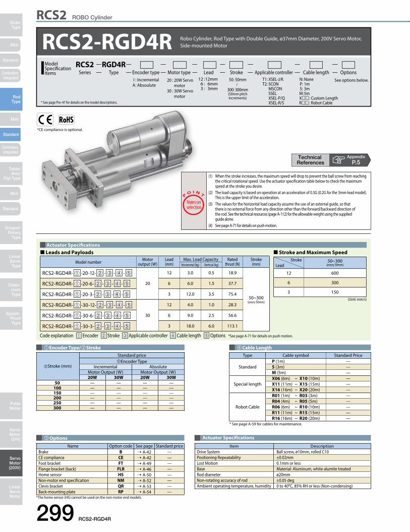
Mini
Mini
Mini
SliderType
RodType
Table/Arm/
Flat Type
Linear ServoType
Gripper/Rotary
Type
Clean-room Type
Splash-ProofType
Pulse Motor
Servo Motor (24V)
Servo Motor (200V)
LinearServo Motor
Standard
Standard
Standard
ControllersIntegrated
ControllersIntegrated
299 RCS2-RGD4R
RCS2 ROBO Cylinder
*CE compliance is optional.
AppendixP.5
RCS2-RGD4R 20 : 20W Servo motor 30 : 30W Servo motor
Lead Stroke Cable length OptionsTypeRGD4R
Encoder type Motor type Applicable controllerSeriesRCS2Model
SpecificationItems
* See page Pre-47 for details on the model descriptions.
T1: XSEL-J/K T2: SCON MSCON SSEL XSEL-P/Q XSEL-R/S
I : Incremental A : Absoulute
N: None P: 1m S: 3m M: 5mX: Custom Length R: Robot Cable
See options below. 12 : 12mm 6 : 6mm 3 : 3mm
50: 50mm
300: 300mm(50mm pitch increments)
Robo Cylinder, Rod Type with Double Guide, ø37mm Diameter, 200V Servo Motor, Side-mounted Motor
(1) When the stroke increases, the maximum speed will drop to prevent the ball screw from reaching the critical rotational speed. Use the actuator specification table below to check the maximum speed at the stroke you desire.(2) The load capacity is based on operation at an acceleration of 0.3G (0.2G for the 3mm-lead model). This is the upper limit of the acceleration.(3) The values for the horizontal load capacity assume the use of an external guide, so that there is no external force from any direction other than the forward/backward direction of the rod. See the technical resources (page A-112) for the allowable weight using the supplied guide alone.(4) See page A-71 for details on push motion.
Cable LengthType Cable symbol Standard Price
StandardP (1m) —S (3m) —M (5m) —
Special lengthX06 (6m) ~ X10 (10m) —X11 (11m) ~ X15 (15m) —X16 (16m) ~ X20 (20m) —
Robot Cable
R01 (1m) ~ R03 (3m) —R04 (4m) ~ R05 (5m) —R06 (6m) ~ R10 (10m) —R11 (11m) ~ R15 (15m) —R16 (16m) ~ R20 (20m) —
* See page A-59 for cables for maintenance.
Encoder Type/Stroke
➁Stroke (mm)
Standard priceEncoder Type
Incremental AbsoluteMotor Output (W) Motor Output (W)20W 30W 20W 30W
50 — — — —100 — — — —150 — — — —200 — — — —250 — — — —300 — — — —
Actuator Specifications
Item DescriptionDrive System Ball screw, ø10mm, rolled C10Positioning Repeatability ±0.02mmLost Motion 0.1mm or lessBase Material: Aluminum, white alumite treatedRod diameter ø20mmNon-rotating accuracy of rod ±0.05 degAmbient operating temperature, humidity 0 to 40oC, 85% RH or less (Non-condensing)
OptionsName Option code See page Standard price
Brake B ➝ A-42 —CE compliance CE ➝ A-42 —Foot bracket FT ➝ A-49 —Flange bracket (back) FLR ➝ A-46 —Home sensor HS ➝ A-50 —Non-motor end specification NM ➝ A-52 —Clevis bracket QR ➝ A-53 —Back-mounting plate RP ➝ A-54 —
*The home sensor (HS) cannot be used on the non-motor end models.
� Leads and Payloads � Stroke and Maximum SpeedActuator Specifications
(Unit: mm/s)
Code explanation ➀ Encoder ➁ Stroke ➂ Applicable controller ➃ Cable length ➄ Options *See page A-71 for details on push motion.
Model number Motor output (W)
Lead(mm)
Max. Load Capacity Ratedthrust (N)
Stroke(mm)Horizontal (kg) Vertical (kg)
RCS2-RGD4R- ➀ -20-12- ➁ - ➂ - ➃ - ➄
20
12 3.0 0.5 18.9
50~300(every 50mm)
RCS2-RGD4R- ➀ -20-6- ➁ - ➂ - ➃ - ➄ 6 6.0 1.5 37.7
RCS2-RGD4R- ➀ -20-3- ➁ - ➂ - ➃ - ➄ 3 12.0 3.5 75.4
RCS2-RGD4R- ➀ -30-12- ➁ - ➂ - ➃ - ➄
30
12 4.0 1.0 28.3
RCS2-RGD4R- ➀ -30-6- ➁ - ➂ - ➃ - ➄ 6 9.0 2.5 56.6
RCS2-RGD4R- ➀ -30-3- ➁ - ➂ - ➃ - ➄ 3 18.0 6.0 113.1
Stroke 50~300(every 50mm)Lead
12 600
6 300
3 150

Dimensional Drawings
Mini
Mini
Mini
SliderType
RodType
Table/Arm/Flat Type
Linear ServoType
Gripper/Rotary Type
Clean-room Type
Splash-ProofType
Pulse Motor
Servo Motor (24V)
Servo Motor (200V)
LinearServo Motor
Standard
Standard
Standard
ControllersIntegrated
ControllersIntegrated
RCS2-RGD4R 300
CAD drawings can be downloaded from the website. www.intelligentactuator.com Appendix
P.15
RCS2 ROBO Cylinder
[Brake-Equipped]
[No Brake]
Pm
20
ø48
Bracket B
Bracket A
311
2029 30 37
7388
100110
2041
st
ℓ
19 (width across flats)
3
(st+74)
933
L
48
3st
MEME SE Home
ø50
ø20
(Ro
d O
D)
Depth 18M10 × 1.25
50.5
98.5
269.5
Nut ANut A
9.5
311 st
19 (width across flats)
3
(st+74)
3st
MEME SE Home
ø20
(Ro
d O
D)
Nut ANut A
ø48 ø50
Pm
47
26
26.5
20
29
100
110
3020
8826
.5
37
4-C2
8-M5 through-hole
15 8
4-C2
4-M5
Bracket A Bracket B
40°
Sec
ure
at le
ast
100
Cable jointconnector *1
Name Externalview Model number Features Maximum number of
positioning pointsInputpower
Power supply capacity
Standardprice
Reference page
Positioner mode
SCON-CA-20 -NP-2-SCON-CA-30D -NP-2-
Up to 512 positioning points are supported.
512 points
Single-phase 100VAC
Single-phase 200VAC
3-phase 200VAC
(XSEL-P/Q/R/S ONLY)
126 VA max.
* Power supply capacity will vary depending on the controller, so please refer to the instruction manual for details.
—
➝ P643
Solenoid valve mode
Actuators can be operated through the same control used for solenoid valves.
7 points
Field network type
Movement by numerical specification is supported. 768 points —
Pulse-train input control
type
Dedicated pulse-train input type (—) —
Positioner multi-axis,
network type
MSCON-C-1-20 - -0-MSCON-C-1-30D - -0-
Up to 6 axes can be operated. Movement by numerical specification is supported.
256 points — ➝ P655
Program control type,
1 to 2 axes
SSEL-CS-1-20 -NP-2-SSEL-CS-1-30D -NP-2-
Program operation is supported. Up to 2 axes can be operated. 20,000 points — ➝ P685
Program control type,
1 to 8 axes
XSEL- -1-20 -N1-EEE-2-XSEL- -1-30D -N1-EEE-2-
Program operation is supported. Up to 8 axes can be operated.
Varies depending on the number of axes connected
— ➝ P695
RCS2-series actuators can be operated with the following controllers. Select an appropriate controller type according to your application.Applicable Controllers
* This is for the single-axis MSCON, SSEL, and XSEL. * indicates the encoder type (I: Incremental / A: Absolute).* indicates the power-supply voltage type (1: 100V / 2: Single-phase 200V). * indicates the XSEL type (J / K / P / Q / R / S).* indicates the power-supply voltage type (1: 100 V / 2: Single-phase 200V / 3: Three-phase 200V). * indicates field network specification symbol.
2D CAD2D
CAD(*1) Connect the motor and encoder cables here. See page A-59 for details on cables.(*2) After homing, the slider moves to the ME, therefore, please watch for any interference with surrounding objects. ME : Mechanical end SE : Stroke end(*3) The orientation of the bolt varies depending on the product.
Stroke 50 100 150 200 250 300
L 20W 227 277 327 377 427 477 30W 227 277 327 377 427 477ℓ 133 183 233 283 333 383
m 20W 80.530W 95.5
P 20W 113.530W 128.5
Weight (kg) 1.9 2.2 2.3 2.6 2.7 3.0
�Dimensions and Weight by StrokeRCS2-RGD4R (without brake)
Stroke 50 100 150 200 250 300
L 20W 227 277 327 377 427 477 30W 227 277 327 377 427 477ℓ 133 183 233 283 333 383
m 20W 123.w530W 138.5
P 20W 156.530W 171.5
Weight (kg) 2.1 2.4 2.5 2.8 2.9 3.2
RCS2-RGD4R (with brake)