iaq concept, energy recovery options, hrw design...
TRANSCRIPT

By
Energy Recovery – Applied to IAQ
Understanding
IAQ Concept, Energy Recovery Options,
HRW Design Parameters and DOAS
By
Milind Mate – Manager Exports (DRI)
Sanjiv Sachdeva – Managing Director (Sauter Middle East)
Mehul Modi – Regional Manager (GESS)
Vivek Thombre – Branch Manager (DRI)
Our Presentation Today
� Indoor Air Quality Concept
� Fresh Air Energy Design Dilemma
� Energy Recovery Options
� Heat Recovery Wheel Evaluation Parameters
� Heat Recovery Wheel Applications Green Buildings / Hospitals
� RH Management Concerns
� DOAS Concept & Technology Options � DOAS Concept & Technology Options
� DOAS Integration with Parallel system / Chilled beams
� Dehumidification Technology for swimming Pools
� Commercial Air & Gas Purification Units
� Cooling Pads Air Conditioning for Dry Places

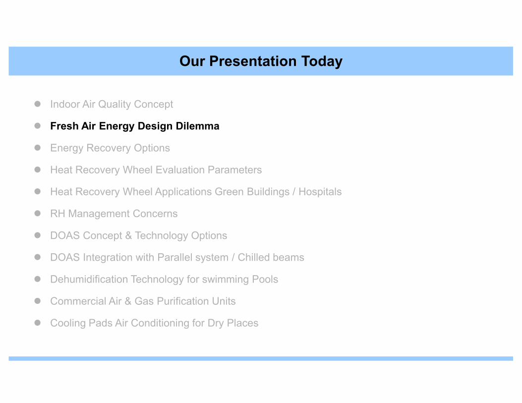
Our Presentation Today
� Indoor Air Quality Concept
� Fresh Air Energy Design Dilemma
� Energy Recovery Options
� Heat Recovery Wheel Evaluation Parameters
� Heat Recovery Wheel Applications Green Buildings / Hospitals
� RH Management Concerns
� DOAS Concept & Technology Options
� DOAS Integration with Parallel system / Chilled beams
� Dehumidification Technology for swimming Pools
� Commercial Air & Gas Purification Units
� Cooling Pads Air Conditioning for Dry Places

IAQ stands for 'Indoor Air Quality'
Indoor Air Quality (IAQ) refer to the nature of the conditioned (Heat/Cool) Air that
circulate throughout space/area where we work and live i.e. the air we breathe
during most of our lives.
What is IAQ?
during most of our lives.

Indoor Air Quality (IAQ)
• Health professionals consistent and persistent concerns on thehealth hazards caused in workplaces and the increasing number oflawsuits all over the world have prompted the HVAC designer to sitback and think.
• With research clearly indicating that we spend 90 % of our timeindoors and the growing scientific evidence that the air indoor isindoors and the growing scientific evidence that the air indoor isalmost 10 to 100 times more polluted than outside, the risk to healthis much greater indoors than outdoors.
• Modern techniques and construction have added to the problem, withmore and more airtight buildings replacing the leaky buildings ofyesteryears.

Outdoor Indoor Pollutants
Air VOCs + CO2
Viruses + Formaldehyde+
Conditioned Space
Viruses + Formaldehyde
Outdoor Air Cause Higher level of
Pollutants Pollution indoors !!

Optimum Humidity Ranges
Decreased in Bar Width
Indicate Decrease in Effect
Optimum
Zone
Bacteria
Viruses
Fungi
MitesMites
Respiratory
infections*
Allergic Rhinitis
and Asthma
Chemical
Interactions
Ozone
Production
10 20 30 40 50 60 70 80 90
Percent Relative Humidity
*Insufficient data above 50% R.H. Source: Sterling: ASHRAE 1985.
�eye, nose and throat irritation
�headache
�fatigue
�reduced concentration
�irritability
Poor IAQ results in
�irritability
�dry skin and nose bleeds . . . . .

Poor IAQ also results in
• Asthma
• Bronchitis
• Dermatitis
• Flu
• Pneumonia
• Sinusitis• Sinusitis
People have varying degrees of sensitivity to humidity, which increasesthe problem.

� Environmental tobacco smoke (ETS)
� Formaldehydes
� Radon
� Asbestos
� VOC from solvents,paints, varnishes, carpets etc.
� Biological organisms like bacteria ,viruses , fungus
INDOOR AIR POLLUTANTS
� Odours and dust &
� All outdoor pollutants - sulphur, nitrogen dioxide, carbon monoxide, high pollen counts, pesticides, chemicals etc.

Methods to Enhance IAQ. . . . to reduce Indoor Air Pollution
Control sourceof pollution
Removepollutants from air
Although, source control is the most effective way of dealing with Indoor Air Quality (IAQ) problem, it is often impractical, expensive and sometimes
Effective Option
expensive and sometimes impossible. Increasing
ventilation/dilutionAir cleaning
• Not a substitute for fresh outside air
• Do not revitalize the air
• Cannot rid indoor air of particulate contaminants
• Have no effect on concentration of pollutants like formaldehyde, carbon monoxide and other gases

Ventilation
Ventilation is the movement of air and it’s contained pollutants to outdoorsand flow of fresh air indoors.
• The flow of fresh air dilutes the concentration of pollutant indoors.
• It is ideal way of keeping indoor air clean.
However, simple mechanical ventilation increases the fresh air
load on conditioning systems resulting increase in tonnage . . .
more energy cost.

Indoor Air Quality (IAQ)

Increase in Ventilation Rate Yields Reduction in Airborne Infections
Source : Nunnelly, R.R., Designing for Absolute Moisture, May, 2002.
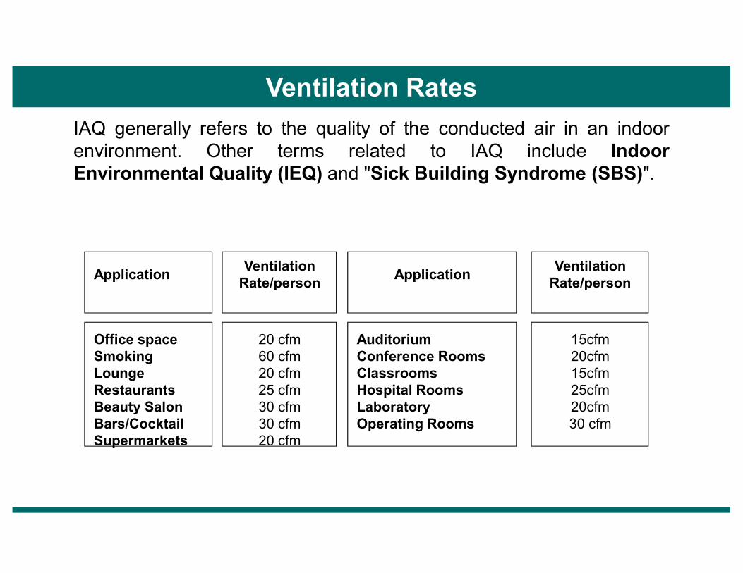
Ventilation Rates
IAQ generally refers to the quality of the conducted air in an indoorenvironment. Other terms related to IAQ include IndoorEnvironmental Quality (IEQ) and "Sick Building Syndrome (SBS)".
ApplicationVentilation Rate/person
Application Ventilation Rate/personRate/person Rate/person
Office spaceSmoking LoungeRestaurantsBeauty SalonBars/CocktailSupermarkets
20 cfm60 cfm20 cfm25 cfm30 cfm30 cfm20 cfm
AuditoriumConference RoomsClassroomsHospital RoomsLaboratoryOperating Rooms
15cfm20cfm15cfm25cfm20cfm30 cfm
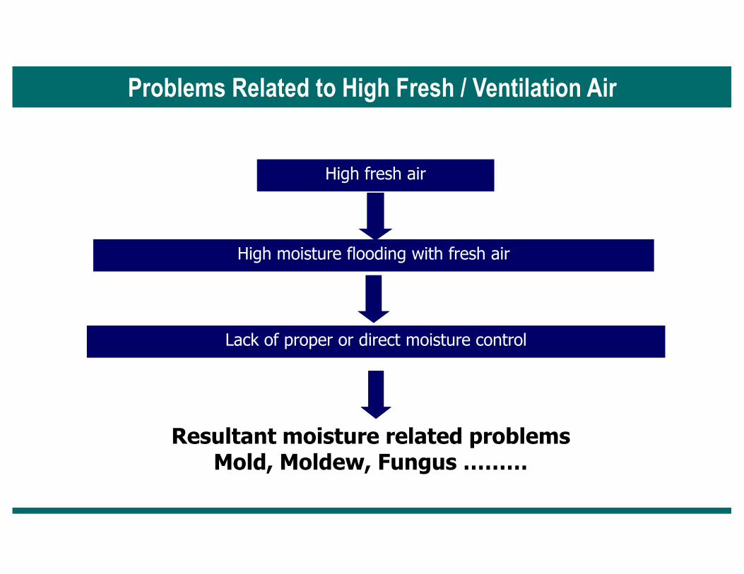
High moisture flooding with fresh air
Problems Related to High Fresh / Ventilation Air
High fresh air
Resultant moisture related problemsMold, Moldew, Fungus ………
Lack of proper or direct moisture control
Ventilation Load
The "Ventilation Load Index" or VLI, is a fairly new term that is gaining popularity in
our industry. It was introduced to emphasize the difference between the sensible and
latent ventilation loads (in ton-hrs/cfm) of outside air introduced inside to a space
neutral condition (72 degrees F/55% RH).

VLI Load Profile
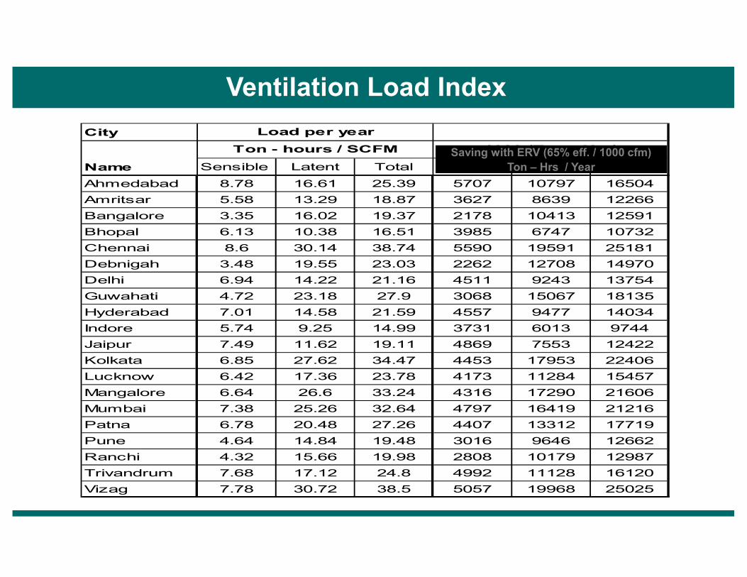
Ventilation Load Index
City
Name Sensible Latent Total Sensible Latent Total
Ahmedabad 8.78 16.61 25.39 5707 10797 16504
Amritsar 5.58 13.29 18.87 3627 8639 12266
Bangalore 3.35 16.02 19.37 2178 10413 12591
Bhopal 6.13 10.38 16.51 3985 6747 10732
Chennai 8.6 30.14 38.74 5590 19591 25181
Debnigah 3.48 19.55 23.03 2262 12708 14970
Delhi 6.94 14.22 21.16 4511 9243 13754
Ton - hours / SCFM 1000 (Ton - Hrs)
Load per year
Saving with ERV (65% eff. / 1000 cfm)Ton – Hrs / Year
Guwahati 4.72 23.18 27.9 3068 15067 18135
Hyderabad 7.01 14.58 21.59 4557 9477 14034
Indore 5.74 9.25 14.99 3731 6013 9744
Jaipur 7.49 11.62 19.11 4869 7553 12422
Kolkata 6.85 27.62 34.47 4453 17953 22406
Lucknow 6.42 17.36 23.78 4173 11284 15457
Mangalore 6.64 26.6 33.24 4316 17290 21606
Mumbai 7.38 25.26 32.64 4797 16419 21216
Patna 6.78 20.48 27.26 4407 13312 17719
Pune 4.64 14.84 19.48 3016 9646 12662
Ranchi 4.32 15.66 19.98 2808 10179 12987
Trivandrum 7.68 17.12 24.8 4992 11128 16120
Vizag 7.78 30.72 38.5 5057 19968 25025
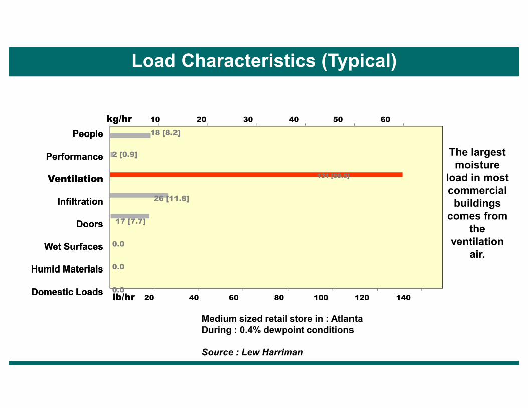
Load Characteristics (Typical)
kg/hr 10 20 30 40 50 60
PeoplePeople
Performance Performance
VentilationVentilation
InfiltrationInfiltration
18 [8.2]
2 [0.9]
131 [59.5]
26 [11.8]
The largest moisture
load in most commercial buildings
lb/hr 20 40 60 80 100 120 140
InfiltrationInfiltration
DoorsDoors
Wet SurfacesWet Surfaces
Humid MaterialsHumid Materials
Domestic LoadsDomestic Loads
17 [7.7]
0.0
0.0
0.0
buildings comes from
the ventilation
air.
Medium sized retail store in : AtlantaDuring : 0.4% dewpoint conditions
Source : Lew Harriman
� Indoor Air Quality Concept
� Fresh Air Energy Design Dilemma
� Energy Recovery Options
� Heat Recovery Wheel Evaluation Parameters
� Heat Recovery Wheel Applications Green Buildings / Hospitals
Our Presentation Today
� RH Management Concerns
� DOAS Concept & Technology Options
� DOAS Integration with Parallel system / Chilled beams
� Dehumidification Technology for swimming Pools
� Commercial Air & Gas Purification Units
� Cooling Pads Air Conditioning for Dry Places
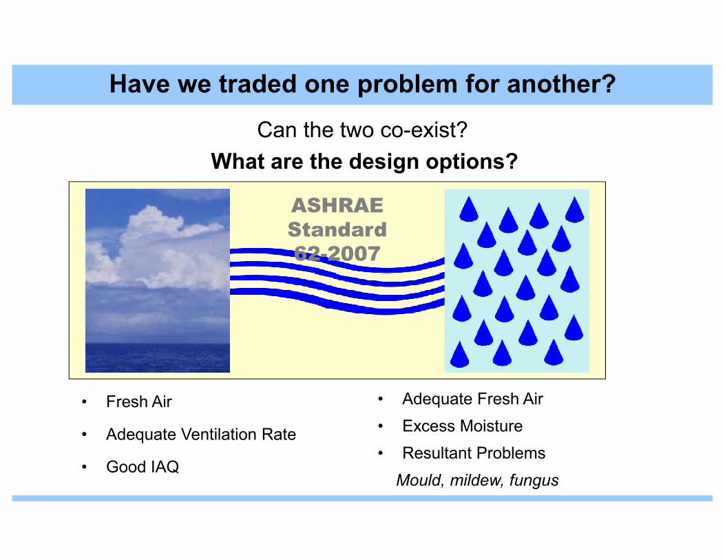
What are the design options?
ASHRAE
Standard
62-2007
Have we traded one problem for another?
Can the two co-exist?
• Fresh Air
• Adequate Ventilation Rate
• Good IAQ
• Adequate Fresh Air
• Excess Moisture
• Resultant Problems
Mould, mildew, fungus

• The conventional energy efficient building practices, resulted in construction of
‘tighter’ building spaces, using re-circulated air for ventilation. Poor design principles
were employed to enable energy conservation in air-conditioned spaces,
jeopardizing the health of the occupants.
• Fresh air ventilation runs contrary to the guidelines being followed by HVAC
professionals. Higher fresh air ventilation needs translate into higher outdoor air
changes per changes, which leads to more air-conditioning loads necessitating
installation of higher capacity plants. This leads to higher initial cost and higher
The Designer’s Dilemma
installation of higher capacity plants. This leads to higher initial cost and higher
energy bills.
• The right humidity levels have to be maintained despite the increased ventilation
rates and also to avoid expensive and inefficient solution like re-heat.
• New standards and increased awareness of the effect of IAQ on health necessitates
the engineers and building designers conceptualize and provide cost effective
solution to indoor air quality requirements.

� Indoor Air Quality Concept
� Fresh Air Energy Design Dilemma
� Energy Recovery Options
� Heat Recovery Wheel Evaluation Parameters
� Heat Recovery Wheel Applications Green Buildings / Hospitals
� RH Management Concerns
Our Presentation Today
� RH Management Concerns
� DOAS Concept & Technology Options
� DOAS Integration with Parallel system / Chilled beams
� Dehumidification Technology for swimming Pools
� Commercial Air & Gas Purification Units
� Cooling Pads Air Conditioning for Dry Places
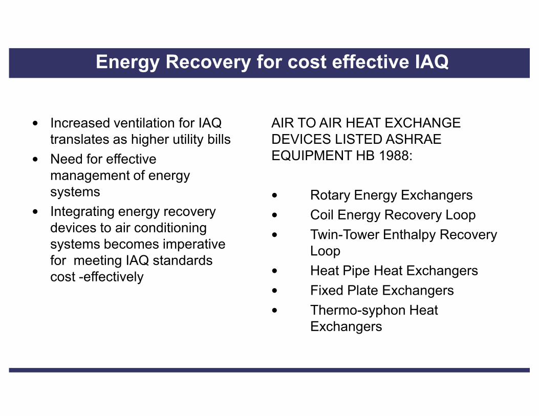
• Increased ventilation for IAQ translates as higher utility bills
• Need for effective management of energy systems
• Integrating energy recovery
AIR TO AIR HEAT EXCHANGE DEVICES LISTED ASHRAE EQUIPMENT HB 1988:
• Rotary Energy Exchangers
• Coil Energy Recovery Loop
Energy Recovery for cost effective IAQ
• Integrating energy recovery devices to air conditioning systems becomes imperative for meeting IAQ standards cost -effectively
• Coil Energy Recovery Loop
• Twin-Tower Enthalpy Recovery Loop
• Heat Pipe Heat Exchangers
• Fixed Plate Exchangers
• Thermo-syphon Heat Exchangers

Flat Plate Core (Counter Flow) Flat Plate Core (Cross Flow)
Rotary Wheel CoreRotary Wheel Core Heat Pipe CoreHeat Pipe Core
Fresh AirFresh AirStreamStream
Fresh AirFresh AirStreamStream
Exhaust Air Exhaust Air StreamStream
Exhaust Air Exhaust Air StreamStream
Heat Recovery Technologies
Rotary Wheel CoreRotary Wheel Core Heat Pipe CoreHeat Pipe Core
Exhaust Air Exhaust Air StreamStream
Fresh AirFresh AirStreamStream
Fresh AirFresh AirStreamStream
Exhaust Air Exhaust Air StreamStream
Heat PipesHeat Pipes
Rotating Heat Rotating Heat WheelWheel
Most Effective Technology for Total Energy Recovery
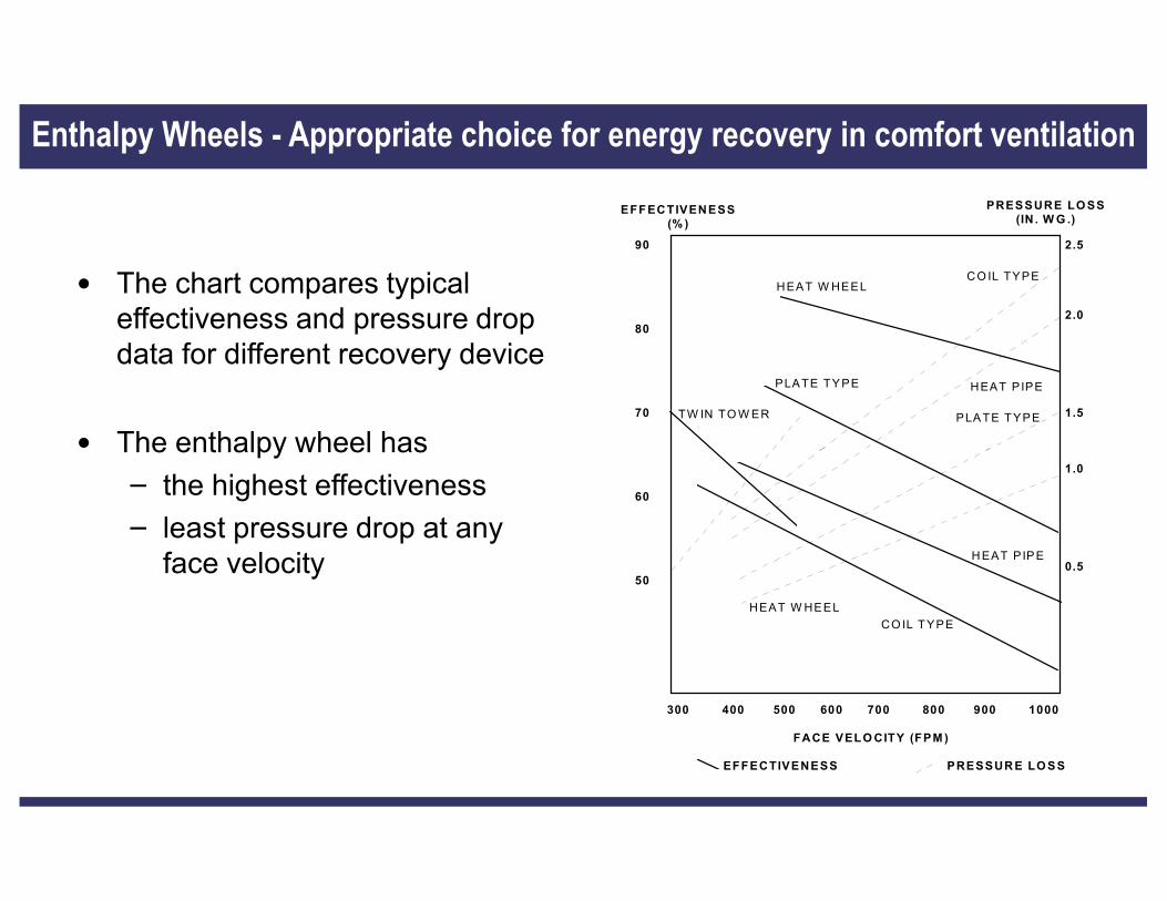
• The chart compares typical effectiveness and pressure drop data for different recovery device
• The enthalpy wheel has
Enthalpy Wheels - Appropriate choice for energy recovery in comfort ventilation
EFFECTIVENESS(% )
PRESSURE LOSS(IN . WG .)
90
80
70
2.5
2.0
1.5
CO IL TYPE
HEAT P IPE
PLA TE TYPE
HEAT W HEEL
PLATE TY PE
TW IN TO W ER
• The enthalpy wheel has
– the highest effectiveness
– least pressure drop at any face velocity
60
50
1.0
0.5
300 400 500 600 700 800 900 1000
FACE VELOCITY (FPM)
EFFECTIVENESS PRESSURE LOSS
H EAT PIP E
CO IL TYPE
HEAT W HEEL

Return AirExhaust Air
25 DEG C, 50% RH9.70 Grm/Kg
42.1o C, 36.6% RH18.7 Grm/Kg
Total Energy Recovery Wheel Principle of Operation
Supply AirOutdoor Air
29.7oC, 47.6% RH12.2 Grm/Kg
460 C, 33%RH 20.7 Grm/Kg

� Indoor Air Quality Concept
� Fresh Air Energy Design Dilemma
� Energy Recovery Options
� Heat Recovery Wheel Evaluation Parameters
� Heat Recovery Wheel Applications Green Buildings / Hospitals
� RH Management Concerns
Our Presentation Today
� RH Management Concerns
� DOAS Concept & Technology Options
� DOAS Integration with Parallel system / Chilled beams
� Dehumidification Technology for swimming Pools
� Commercial Air & Gas Purification Units
� Cooling Pads Air Conditioning for Dry Places

Following are some parameters based on which one can evaluate each optionand then test it for ones application. The various parameters important for pickingup the right option are
i. Ventilation load profile
ii. Efficiency profile
iii. Substrate type / Desiccant type
iv. Pressure drops
Evaluation Parameters for Choosing Right Technology
iv. Pressure drops
v. Cross contamination
vi. Microbial growth on substrate
vii. Fire Rating
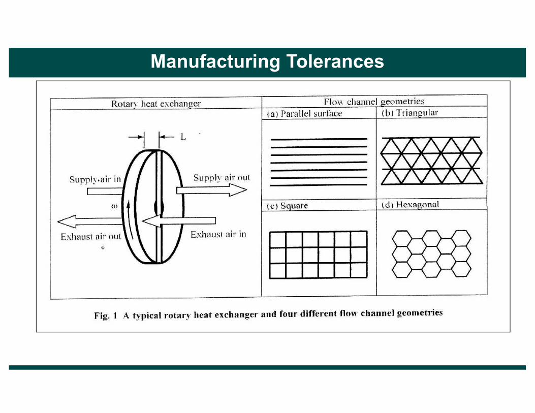
viii. Manufacturing Tolerances
ix. Structural Strength
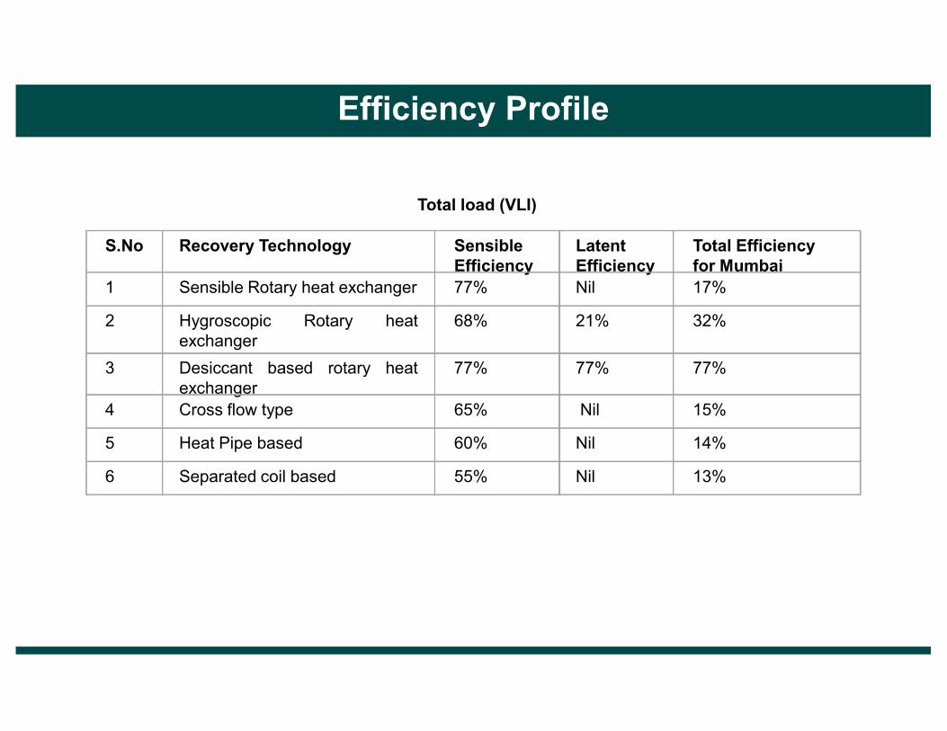
Total load (VLI)
S.No Recovery Technology SensibleEfficiency
LatentEfficiency
Total Efficiency for Mumbai
1 Sensible Rotary heat exchanger 77% Nil 17%
2 Hygroscopic Rotary heatexchanger
68% 21% 32%
3 Desiccant based rotary heat 77% 77% 77%
Efficiency Profile
3 Desiccant based rotary heatexchanger
77% 77% 77%
4 Cross flow type 65% Nil 15%
5 Heat Pipe based 60% Nil 14%
6 Separated coil based 55% Nil 13%

Latent Efficiency Desiccant Carryover
Etched (oxidized Alumunium) Low High
Molecular Sieve 3AO High Negligible
Molecular Sieve 4AO High Moderate
Substrate / Desiccant type
Molecular Sieve 4AO High Moderate
Silica Gel High High
Source : (GTRI report)

Pressure drops across the heat recovery wheel are dependent on followingcharacteristics:
• Pitch Height/Width of Flute
• Substrate Type
• Fouling
• Heat Exchanger Width
Pressure Drops
Pitch ProfileFlute Geometry
p-pitch
h-height
d-depthCoating1. Thickness (gsm)2. Isotherm3. Heat of adsorption 4. Heat Capacity
Substrate1. Thickness (gsm)2. Specific Heat3. Specific Gravity
Recommended 0.1” per 100 FPM of Face Velocity

Pressure Drop
Sensible Efficiency
Latent Efficiency
200mm deep etched aluminum substrate HRW
0.51” 68% 21%
Pressure Drops
270 mm deep desiccant based aluminum substrate HRW
0.76” 78% 76%
100 mm deep synthetic fibre HRW 1.24” 70.6% 66.8%

Variations in Pore Diameter among Desiccants
EF
DCA B
Cross Contamination
3 5 10 25 50 100
Pore Diameter in Angstroms (Å)A - 3Å Molecular SieveB - 4Å Molecular SieveC - 5 Å Molecular SieveD - 10Å Molecular SieveE - Activated AluminaF - Silica Gel
4
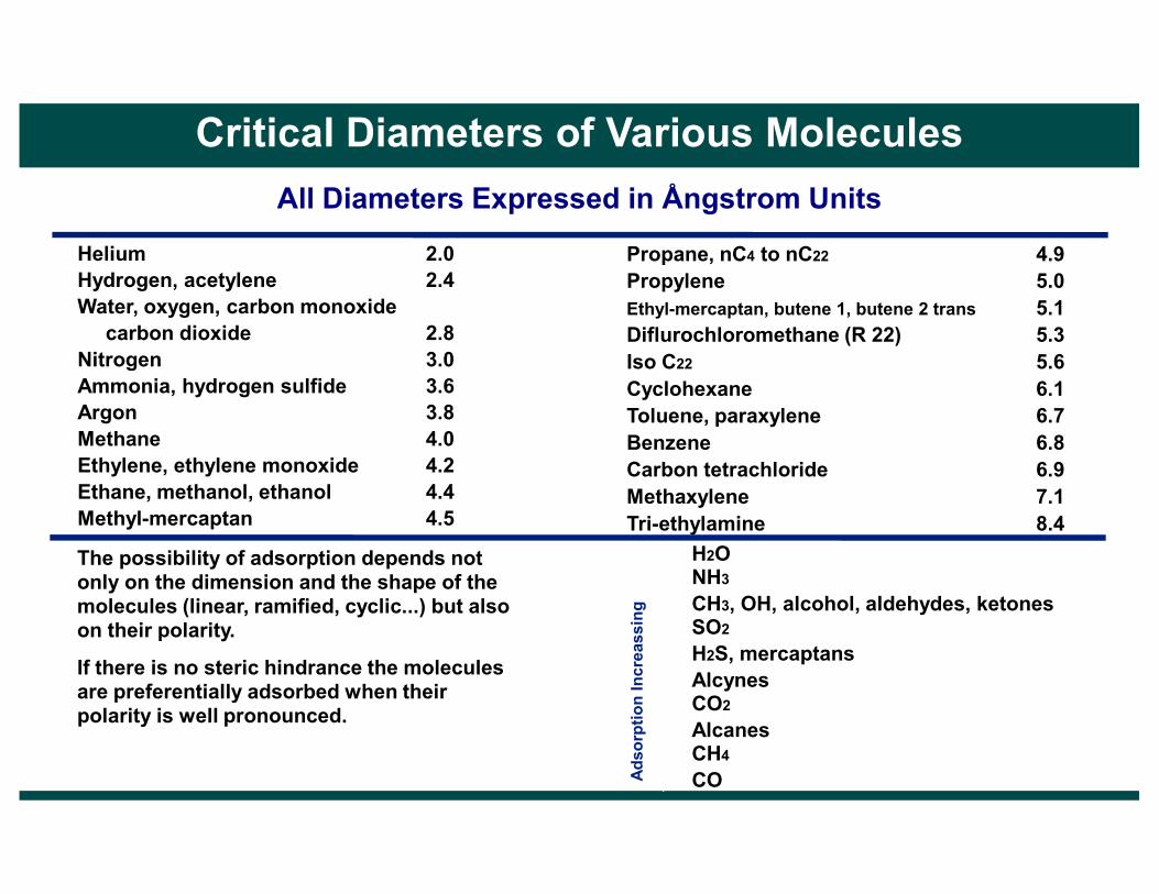
All Diameters Expressed in Ångstrom Units
Helium 2.0Hydrogen, acetylene 2.4Water, oxygen, carbon monoxidecarbon dioxide 2.8
Nitrogen 3.0Ammonia, hydrogen sulfide 3.6Argon 3.8Methane 4.0
Propane, nC4 to nC22 4.9Propylene 5.0Ethyl-mercaptan, butene 1, butene 2 trans 5.1Diflurochloromethane (R 22) 5.3Iso C22 5.6Cyclohexane 6.1Toluene, paraxylene 6.7Benzene 6.8
Critical Diameters of Various Molecules
Methane 4.0Ethylene, ethylene monoxide 4.2Ethane, methanol, ethanol 4.4Methyl-mercaptan 4.5
Benzene 6.8Carbon tetrachloride 6.9Methaxylene 7.1Tri-ethylamine 8.4
The possibility of adsorption depends not only on the dimension and the shape of the molecules (linear, ramified, cyclic...) but also on their polarity.
If there is no steric hindrance the molecules are preferentially adsorbed when their polarity is well pronounced.
H2ONH3CH3, OH, alcohol, aldehydes, ketonesSO2H2S, mercaptansAlcynesCO2AlcanesCH4COA
dsorption Increassing

Common Pollutants
Molecular sieve 3AO
Molecular sieve 4AO
Oxidized Aluminum
Silica Gel
Acetaldehyde 0% >30% >50% >50%
Acetic Acid 0% 30-50% >50% >50%
Acetone 0% <10% 10-30% 10-30%
Amyl Alcohol 0% 0% 30-50% 30-50%
Benzene 0% 0% 10-30% 10-30%
Butanol 0% 10-30% 30-50% 30-50%
Butylacetate 0% <10% 10-30% 10-30%
Cross Contamination
Butylacetate 0% <10% 10-30% 10-30%
Butryic Acid 0% 0% >50% >50%
Carbon Dioxide 0% 1% 1-20% 1-20%
Chloroform 0% 0% 30-50% 30-50%
Cyclohexane 0% 0% <10% <10%
Dichlorobenzene 0% 0% <10% <10%
Dioxane 0% 30-50% >50% >50%
Ethanol 0% 30-50% 30-50% 30-50%
Ethyl Acetate 0% 0% 10-30% 10-30%
Desiccant Carryover (source Semco)
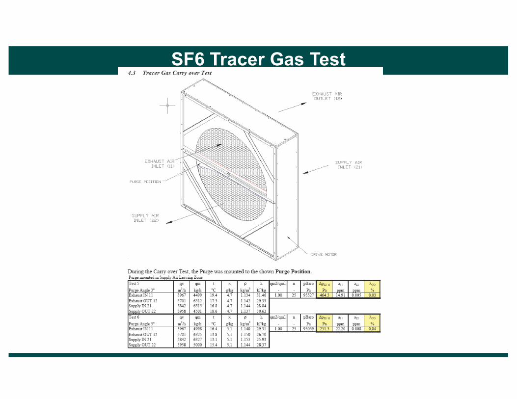
SF6 Tracer Gas Test

Microbial growth
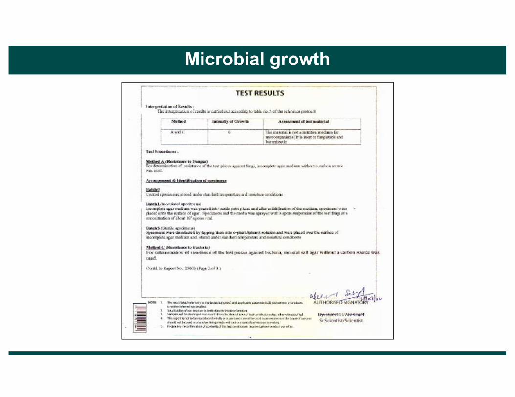
Microbial growth

Microbial growth

Fire Rating

Fire Rating
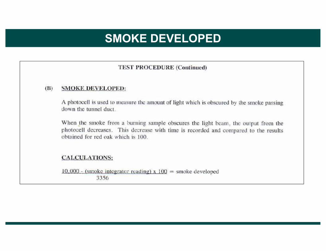
SMOKE DEVELOPED

SMOKE DEVELOPED
Manufacturing Tolerances

Couple
Torque
Air flow
Structural Strength
Air flow
Torque

Wheel
Type
Sensible
Efficiency
Latent
Efficiency
TR
Recovery
Annual
Energy
Saving
s
(A)
Pressure
Drop
(Pa)
Energy
Consumption
of TFA/year (B) (with Additional
200 pascal for
external/ filters)
Net
savings/
Year
C= (A-B)
Savings in
First cost
due to TR
Reduction
(D)
Savings
for Ist
Year of
operati
ons
C+D
Savings
for 15
Years
E=15C+
D
Wheel
A
Wheel
B
68% 21% 24.8 3,46,000/- 170 1,53,120/- 1,92,880- 6,20,000/- 8,12,880- 35,13,200/-
77% 77% 62.8 8,80,000/- 195 1,63,152/- 7,16,848/- 15,70,000/- 22,86,848/- 1,23,22,720/-
LCS (Life Cycle Savings)
Wheel
C68.7% 64.6% 53.8 7,47,500/- 333 2,11,200/- 5,36,300/- 13,45,000/- 18,81,300/- 93,89,500/-
Outside Conditions = 90DB/86WB
Inside Conditions = 72 DB / 62 WB / 55% RH
Wheel A = 200 mm deep Aluminum substrate Hygroscopic wheel
Wheel B = 270 mm deep Aluminum substrate MS 3A0 coated wheel
Wheel C = 100 mm deep synthetic fibre MS 4A0 wheel
CFM = 10000 (1800 mm wheel dia)
CITY = KOLKATA
VLI = 34.47 TR-hr/cfm/yr
CALL CENTRE = 16 HR OPERATION
300 days per yr
Power Consumption = 1.1 kw/ TR
Chilled Water System = Rs. 25000/ TR

WheelType
CrossContamination
Microbialgrowth
FireRating
StructuralStrength
ManufacturingTolerances
Wheel A
Wheel B
HIGH NIL SUITABLE MODERATE MODERATE
NIL NIL SUITABLE HIGH NEGLIGIBLE
Qualitative Factors
Wheel C MODERATE PROBABILITY RISK LOW MODERATE
Wheel A = 200 mm deep Aluminum substrate Hygroscopic wheel
Wheel B = 270 mm deep Aluminum substrate MS 3A0 coated wheel
Wheel C = 100 mm deep synthetic fibre MS 4A0 wheel

While finalizing recovery system it is also important that some more aspects be kept in mind while finalizing HVAC design. Some such considerations are
• Balanced/ Unbalanced air flow
• Corrosive Environment
• Redundancy
• Casing leakage Standard
Other Considerations
• Casing leakage Standard
• Space requirements/ Duct adequacies
• Purge

Many designers simply use 50 – 70 % of the exhaust air (leave rest for leakage) to recover energy citing the need to keep positive pressure to reduce infiltration.
Although the thought is fine but modern building have very low leakage class and a 10%unbalance in the supply air/ exhaust air is sufficient to satisfy that need.
Dumping 30-40% exhaust is a waste of energy.
Unbalance = X 100 %SA – EA
SA
Balanced/Unbalanced Air Flow
Corrosive EnvironmentIf the internal or external environment is highly corrosive i.e. has a very level ofacidic or basic compounds, adequate case should be taken to choose the rightsubstrate. Many manufacturers specify special substrate for highly acidicenvironments like battery manufacturing etc. Even for mildly corrosiveenvironment like Animal houses special wheels made by manufacturers, areavailable. Also organic vapours also effect the latent recovery of the wheel andhas a masking effect on desiccant. Special filters for such application areadvised.
Once a recovery system is put in place, automatically the load requirementreduces. It has been a practice to keep the chiller tonnage as designed (withoutrecovery) and use the recovery device for energy saving only.
Such redundancy not only increases the first cost but also makes the chillers run
Redundancy
Such redundancy not only increases the first cost but also makes the chillers runon partial loads all the time.
This reduces the efficiency of chiller as they are most efficient of full load.

OutsideAir SupplyAir
Theory of Operation - A specific volume of air is allowed to bypass into exhaustair stream, minimizing carryover of contaminants from return air.
Illustration of Wheel Purge Section
ReturnAir
WheelRotation
ExhaustAir
Purge angle is a function of air velocity,and purge volume is afunction of wheel volumeand rotation speed.

Outside Air Supply Air
Carryover Zone Wheel Rotation
Media Carry Over
Return AirExhaust Air
Due to the fixed volume of air being transferred as the wheelrotates, cross contamination of the air streams occurs.

Efficiency : S.E. > 75% L.E. > 75%Pressure Drop : less than 0.1” per 100 FPMSubstrate : AluminumDesiccant : Desiccant MS 3A0
Microbial Growth : Tested for 0% growth of fungi / Bacteria as per DINEN ISO 846.
Fire Rating : Should be 0% Flame spread0-5 class for smoke developed
Manufacturing
CHECK LIST
ManufacturingTolerance : Minimum deviation from mean hydraulic diameter
vertical windingStructural Strength : Suggested 200 mm deep or higherPurge : MustBalance : 10% unbalanceCorrosiveEnvironment : Right substrateRedundancy : Remove extra chiller capacity
Casing : Class B of Eurovent Standard

� Indoor Air Quality Concept
� Fresh Air Energy Design Dilemma
� Energy Recovery Options
� Heat Recovery Wheel Evaluation Parameters
� Heat Recovery Wheel Applications Green Buildings / Hospitals
Our Presentation Today
� RH Management Concerns
� DOAS Concept & Technology Options
� DOAS Integration with Parallel system / Chilled beams
� Dehumidification Technology for swimming Pools
� Commercial Air & Gas Purification Units
� Cooling Pads Air Conditioning for Dry Places

A green building is an environmentally sustainable building-designed,constructed and operated to minimize the total environmental impacts.
The main strategy to achieve a green building status includes:
� Reduced energy consumption
� Better IEQ (Indoor Environmental Quality)
Green Building
� Better IEQ (Indoor Environmental Quality)
� Water conservation
� Recycling waste

� LEED (Leadership in Energy & Environmental design) is a “Green BuildingRating System” which attempts to certify and push the advancement of aglobal implementation of green buildings and development standards.
� Under LEED extra points can be gained by increasing the Fresh Air Quantityby at least 30% above the minimum rates required by ASHRAE standard 62%
LEED
by at least 30% above the minimum rates required by ASHRAE standard 62%2007 as determined by EQ-requisite 1.

The LEED standard states “Increase breathing zone outdoor air ventilation rates toall occupied spaces by at least 30% above the minimum rates required by ASHRAEStandard 62.1-2007 as determined by EQ Prerequisite 1”.
This increased amount of ventilation has definitely solved IAQ related problems, butthe inability to maintain the right humidity by our HVAC systems has lead us to otherproblems.
Mold & Mildew are serious dilemma in itself, which are caused by lack of humidity
Outdoor Air Requirements for Ventilation of Air Conditioned Spaces
Mold & Mildew are serious dilemma in itself, which are caused by lack of humiditycontrol. The question is “Have we Traded one problem with the other”.

Fresh Air Facts
Olympia Tech. Park - Chennai, India
Fresh Air Facts� Internal room comfort at 730 F +_ 2 and RH not exceeding 60% as against a prevailing norm of
730 F +_ 2 and RH not exceeding 65 %.
� Installation of carbon dioxide sensors to monitor indoor air quality and replace stale CO2 laden air with a fresh in-draft whenever C02 exceeds a certain level.
� Planned indoor fresh air quality at 20 CFM per person (ASHRAE Standards) as against the prevailing norm of 15 CFM.
� Air replacement cycle adapted to the number of people present in the indoor area; when the number of people declined, the sensors monitor this accordingly and slow down the air replacement frequency from five per hour to two per hour and vice versa.
� 102 no.'s of Treated Fresh Air Units model FLE-150 with Heat Recovery Wheels Model HRW-950, each handles 2400 cfm of fresh air.

• HOSPITALS • NURSING HOMES • CLINICS ...
Special Areas� Operation Theaters � Nurseries� Burn Wards� ICUs� Labs
Why do you need to Treat Fresh Air in
� Labs� Isolation Wards (TB, HIV, etc.)
To
� Avoid infection from spreading� Maintain IAQ� Keep Utility/Air conditioning Bills down

� To restrict air movement in and between various depts.
� For ventilation and filtration V.
� To dilute and remove contamination--
� odour, airborne micro-organisms, viruses, hazardous chemical and
Hospital Vs. General Building Airconditioning
� odour, airborne micro-organisms, viruses, hazardous chemical and radioactive substances.
� Varying temperature and humidity requirements.
� Design sophistication neededV
� For accurate control of environmental conditions

Source: ASHRAE STANDARD 62.1

Good IAQ and high energy efficiency in Medicity aremaintained through properly designed HVAC systems.
DRI has installed 24 units of Treated Fresh Air Units(TFAs) to ensure considerable reduction in installedtonnage, reduction in utility bills for entire life cycle,enhanced IAQ and productivity and reduced health risks.
Medicity Hospital, India
� Total Fresh Air provided by DRI TFA's = 1,19,300 cfm
� Air Conditioning tonnage reduction = 526 TR

� Indoor Air Quality Concept
� Fresh Air Energy Design Dilemma
� Energy Recovery Options
� Heat Recovery Wheel Evaluation Parameters
� Heat Recovery Wheel Applications Green Buildings / Hospitals
Our Presentation Today
� RH Management Concerns
� DOAS Concept & Technology Options
� DOAS Integration with Parallel system / Chilled beams
� Dehumidification Technology for swimming Pools
� Commercial Air & Gas Purification Units
� Cooling Pads Air Conditioning for Dry Places
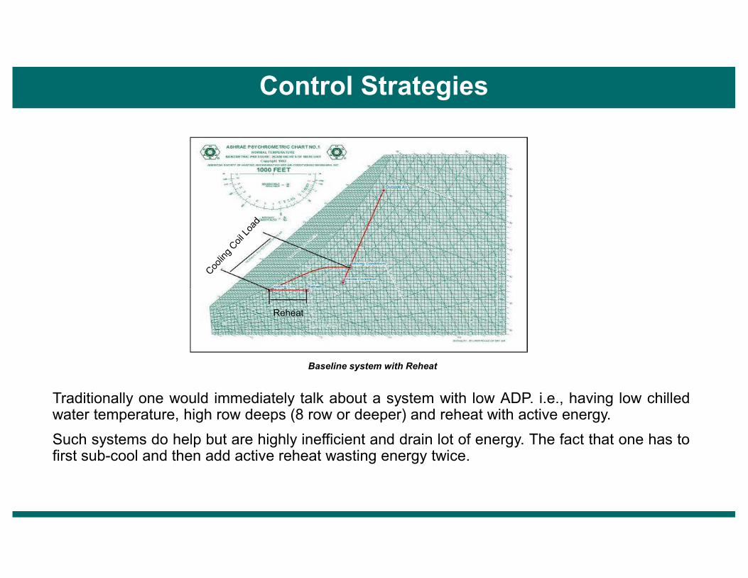
Control Strategies
Traditionally one would immediately talk about a system with low ADP. i.e., having low chilledwater temperature, high row deeps (8 row or deeper) and reheat with active energy.
Such systems do help but are highly inefficient and drain lot of energy. The fact that one has tofirst sub-cool and then add active reheat wasting energy twice.
Baseline system with Reheat
Reheat

Moisture removal by aconventional cooling unit issmall or negligible unless therun time is in excess of 40 to50%.
Research by Hensender
10
5
Measured Cooling Coil Performance @ Rated Conditions
Latent Capacity (1,000 Btu/h)
ON Cycle
This is what happens in conventional air-conditioning units handling high moisture loads with little sensible loads.
An example of passive Humidity/Moisture control in a 3 ton unit
After the compressor
shuts off, moisture
condensed on
the cooling coil
re-evaporates
Research by Hensender
0 10 20 30 4050
Time (min.)
5
0
–5
–10
Latent Capacity (1,000 Btu/h)
Compressor
CycleMoistur
eRemoval OFF
CycleMoistur
eAddition

� Indoor Air Quality Concept
� Fresh Air Energy Design Dilemma
� Energy Recovery Options
� Heat Recovery Wheel Evaluation Parameters
� Heat Recovery Wheel Applications Green Buildings / Hospitals
Our Presentation Today
� RH Management Concerns
� DOAS Concept & Technology Options
� DOAS Integration with Parallel system / Chilled beams
� Dehumidification Technology for swimming Pools
� Commercial Air & Gas Purification Units
� Cooling Pads Air Conditioning for Dry Places

DOAS Approach
� Divide the load into the two components i.e. Sensible & Latent.
� Approach commonly referred to as the “Divide and Conquer”.
� All the latent load brought by outside air is removed at the source & also air is supplied at a low dew point to take care of internal latent load.
� The parallel internal cooling devices are then limited to take care of sensible cooling load.

DOAS Sample Calculation
Consider a two storied Call Center in Mumbai with the following load profile
1) Peak Wet Bulb temperature with mean = 93OF DB/82O
coincidental dry bulb (0.4%) (peak enthalpy) FWB/149 gr/lb2) Inside condition = 72OF DB/55%
RH/65gr/lb3) Inside Load patternGROUND FLOOR (GF)Effective room Sensible Heat = 451680 Btu/hrEffective room Latent Heat = 98000 Btu/hrOccupancy = 300 PersonsFIRST FLOOR (FF)Effective room Sensible Heat = 515832 Btu/hrEffective room Latent Heat = 101000 Btu/hrOccupancy = 325 Persons4) Outdoor Air FlowsGROUND FLOOR (GF) = 300 x 20 = 6000 cfm with 20 cfm per personFIRST FLOOR (FF) = 325 x 20 = 6500 cfm5) Humidity Ratio rise for DOAS to maintain 65 gr/lb insideGROUND FLOOR (GF)GROUND FLOOR (GF)Effective room Latent Heat = 98000 Btu/hrBypassed OA Latent Heat (6000 x (149-65) x0.68x0.12) = 41126 Btu/hr1.2 - Bypass Factor Internal Latent Loads W/o OA load = 56874 Btu/hrHumidity Rise ∆WGF = 56874 = 13.9gr/lb
0.68 x 6000FIRST FLOOR (FF)Effective room Latent Heat = 101000 Btu/hrBypassed OA Latent Heat (6500 x (149-65) x0.68x0.12) = 44554 Btu/hrInternal Latent Loads W/o OA load = 56446 Btu/hrHumidity Rise ∆WFF = 56446 = 12.8gr/lb
0.68 x 6500Hence we choose ∆W Selected = 13.9gr/lb6) Supply air dew point (DOAS)
W supply = W Inside– ∆W Selected = 65 – 13.9 = 51.1 gr/lb
T supply = 49OF Dew point7) Supply air Temperature (DOAS) = 70OF
Hence one can design a Dedicated Outside Air System with 70OF DB/ 49O F DP as supply air condition and internal AHU’s will work as sensible cooling devices only.
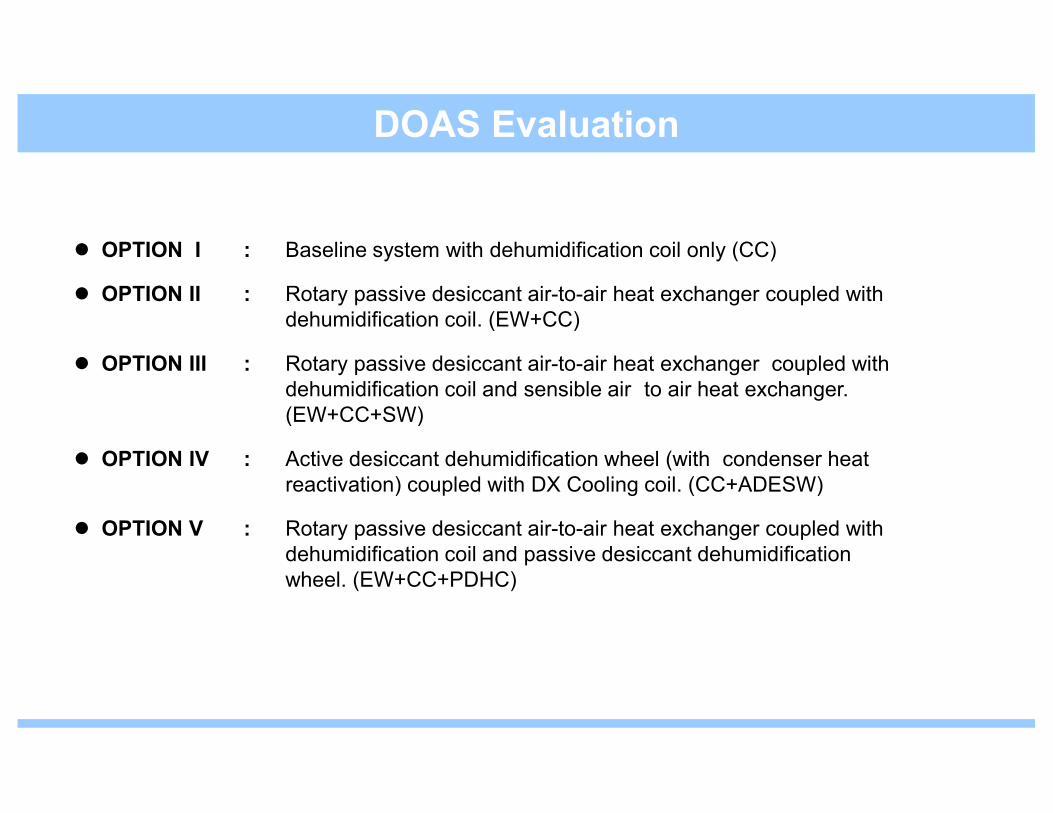
� OPTION I : Baseline system with dehumidification coil only (CC)
� OPTION II : Rotary passive desiccant air-to-air heat exchanger coupled with dehumidification coil. (EW+CC)
� OPTION III : Rotary passive desiccant air-to-air heat exchanger coupled with dehumidification coil and sensible air to air heat exchanger. (EW+CC+SW)
DOAS Evaluation
(EW+CC+SW)
� OPTION IV : Active desiccant dehumidification wheel (with condenser heat reactivation) coupled with DX Cooling coil. (CC+ADESW)
� OPTION V : Rotary passive desiccant air-to-air heat exchanger coupled with dehumidification coil and passive desiccant dehumidification wheel. (EW+CC+PDHC)

Schedule of DOAS System with Cooling Coil

Schedule of DOAS with Enthalpy Wheel and Cooling Coil
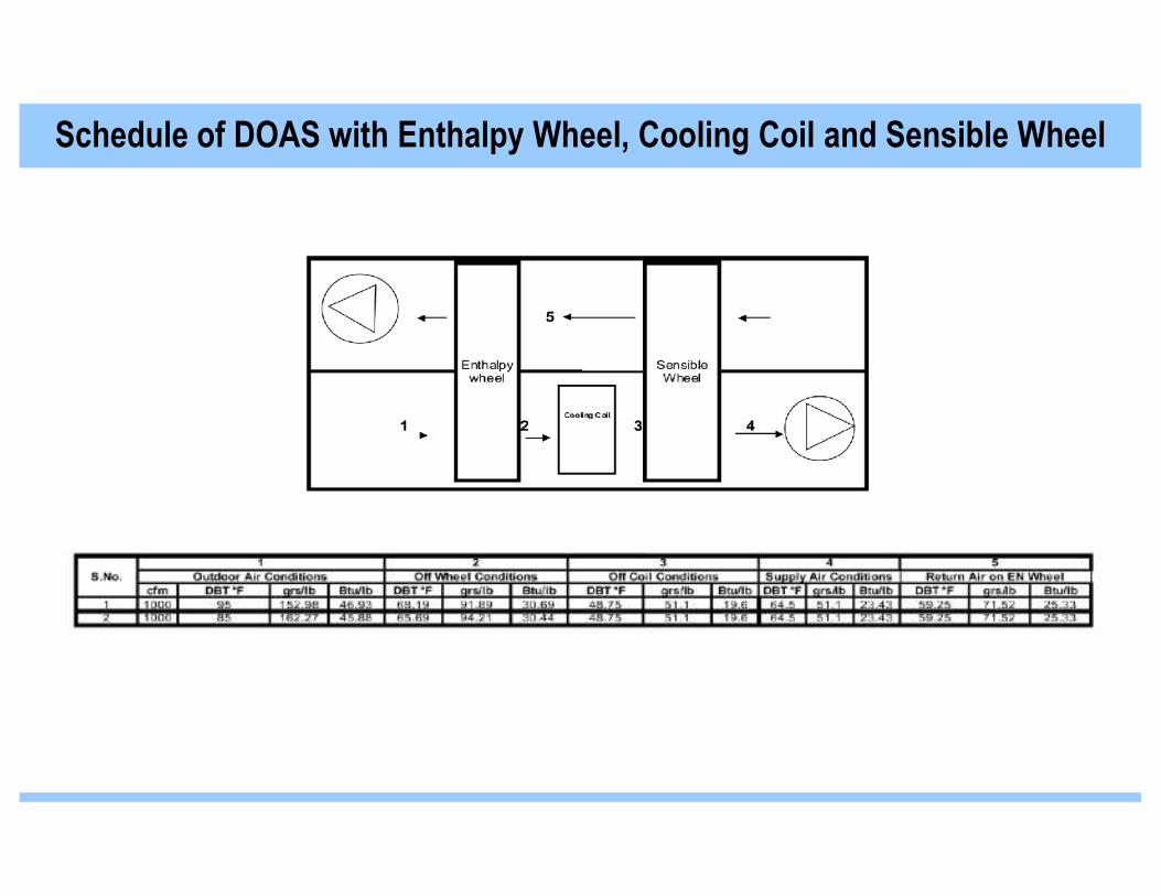
Schedule of DOAS with Enthalpy Wheel, Cooling Coil and Sensible Wheel

(React with Condenser Heat at 120°°°°F)
Schedule of DOAS with Cooling Coil and Active Desiccant Wheel
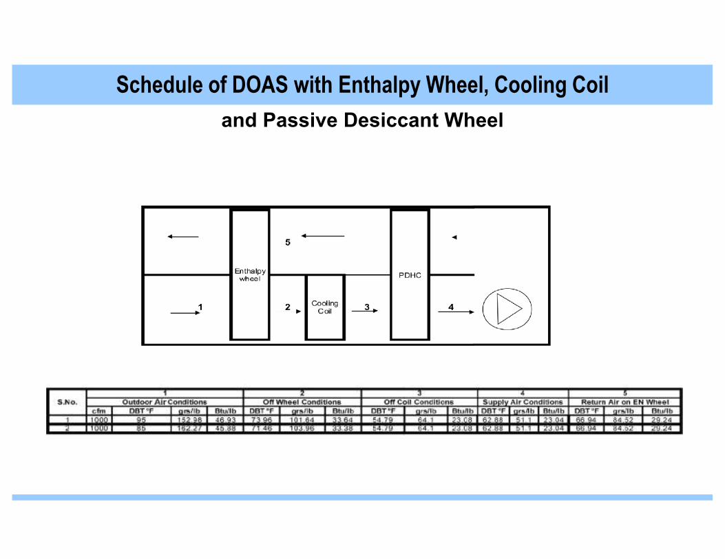
and Passive Desiccant Wheel
Schedule of DOAS with Enthalpy Wheel, Cooling Coil

System load at Mumbai Monsoon Condition

System load at Mumbai Summer Condition

The Ultimate Fresh Air HVAC System

Psychometric Process

Working Principle of Passive Desiccant Wheel
The unique passive desiccant wheel (Patent Pending) has the ability to be regenerated with the50% RH room return air allowing for substantial moisture removal through dehumidification ofthe saturated (100% RH) Fresh Air being supplied to the room. This is intelligently controlled bythe DRISmart EMS (Energy Management System) to regulate speed optimization for differentload conditions and different outside conditions.

� Indoor Air Quality Concept
� Fresh Air Energy Design Dilemma
� Energy Recovery Options
� Heat Recovery Wheel Evaluation Parameters
� Heat Recovery Wheel Applications Green Buildings / Hospitals
Our Presentation Today
� RH Management Concerns
� DOAS Concept & Technology Options
� DOAS Integration with Parallel system / Chilled beams
� Dehumidification Technology for swimming Pools
� Commercial Air & Gas Purification Units
� Cooling Pads Air Conditioning for Dry Places
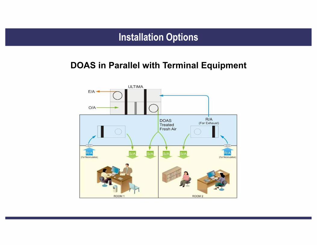
DOAS in Parallel with Terminal Equipment
Installation Options

DOAS in Series with Terminal Equipment
Installation Options

When using the DOAS approach the internal cooling devices work only as sensible coolingdevices. The options available for internal cooling / heating are:
Parallel Sensible Cooling Options
Unitary ACs
Fan Coil Units
Radiant Cooling Panels
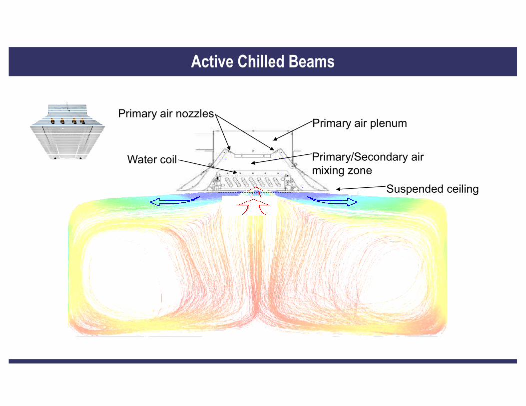
Primary air plenum
Suspended ceiling
Water coil
Primary air nozzles
Primary/Secondary air mixing zone
Active Chilled Beams
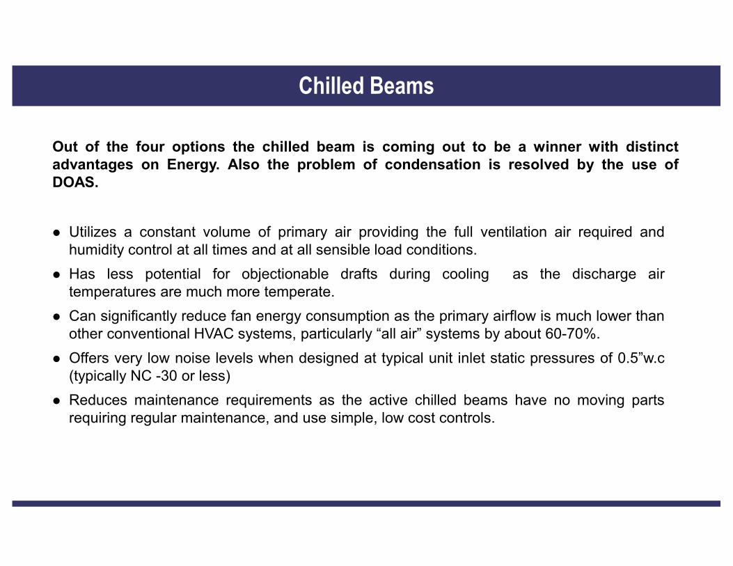
Out of the four options the chilled beam is coming out to be a winner with distinctadvantages on Energy. Also the problem of condensation is resolved by the use ofDOAS.
� Utilizes a constant volume of primary air providing the full ventilation air required andhumidity control at all times and at all sensible load conditions.
� Has less potential for objectionable drafts during cooling as the discharge air
Chilled Beams
temperatures are much more temperate.
� Can significantly reduce fan energy consumption as the primary airflow is much lower thanother conventional HVAC systems, particularly “all air” systems by about 60-70%.
� Offers very low noise levels when designed at typical unit inlet static pressures of 0.5”w.c(typically NC -30 or less)
� Reduces maintenance requirements as the active chilled beams have no moving partsrequiring regular maintenance, and use simple, low cost controls.

� Indoor Air Quality Concept
� Fresh Air Energy Design Dilemma
� Energy Recovery Options
� Heat Recovery Wheel Evaluation Parameters
� Heat Recovery Wheel Applications Green Buildings / Hospitals
Our Presentation Today
� RH Management Concerns
� DOAS Concept & Technology Options
� DOAS Integration with Parallel system / Chilled beams
� Dehumidification Technology for swimming Pools
� Commercial Air & Gas Purification Units
� Cooling Pads Air Conditioning for Dry Places
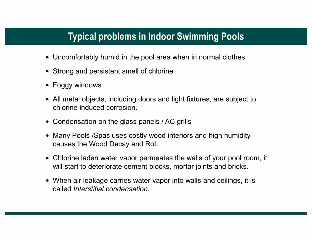
• Uncomfortably humid in the pool area when in normal clothes
• Strong and persistent smell of chlorine
• Foggy windows
• All metal objects, including doors and light fixtures, are subject to chlorine induced corrosion.
• Condensation on the glass panels / AC grills
Typical problems in Indoor Swimming Pools
• Condensation on the glass panels / AC grills
• Many Pools /Spas uses costly wood interiors and high humidity causes the Wood Decay and Rot.
• Chlorine laden water vapor permeates the walls of your pool room, it will start to deteriorate cement blocks, mortar joints and bricks.
• When air leakage carries water vapor into walls and ceilings, it is called Interstitial condensation.
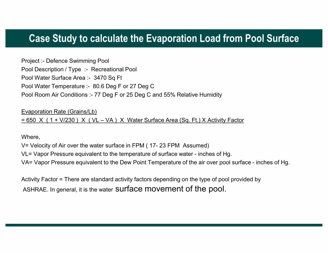
Project :- Defence Swimming Pool
Pool Description / Type :- Recreational Pool
Pool Water Surface Area :- 3470 Sq Ft
Pool Water Temperature :- 80.6 Deg F or 27 Deg C
Pool Room Air Conditions :- 77 Deg F or 25 Deg C and 55% Relative Humidity
Evaporation Rate (Grains/Lb)
= 650 X ( 1 + V/230 ) X ( VL – VA ) X Water Surface Area (Sq. Ft.) X Activity Factor
Case Study to calculate the Evaporation Load from Pool Surface
Where,
V= Velocity of Air over the water surface in FPM ( 17- 23 FPM Assumed)
VL= Vapor Pressure equivalent to the temperature of surface water - inches of Hg.
VA= Vapor Pressure equivalent to the Dew Point Temperature of the air over pool surface - inches of Hg.
Activity Factor = There are standard activity factors depending on the type of pool provided by
ASHRAE. In general, it is the water surface movement of the pool.

Therefore ( from the vapor pressure tables & ASHRAE standards)
VL= 1.05372 at pool Water Temperature of 80.6 Deg F
VA= 0.51527 at Dew Point Temperature of Room Air that is 59.6 Deg F
Activity Factor = 0.65 for Recreational
Now Substituting the Values in the formula
VL- VA = 1.05372 – 0.51527 = 0.53845 inches of Hg
CASE STUDY CONTINUATION
Evaporation Rate (Grains/Lb)
= 650 X ( 1 + V/230 ) X ( VL – VA ) X Water Surface Area (Sq. Ft.) X Activity Factor
= 650 X ( 1 + 23/230 ) X (0.53845 ) X 3470 (Sq. Ft.) X 0.65
Evaporation Rate = 885795 Grains/ Hr OR 57.5 Kg/ Hr
Note:- Always keep pool water temperature is kept 1 Deg C or 2 Deg F lower than the Room temperature to avoid chilling effect on the human body.

SYSTEM FLOW DIAGRAM

● The pool dehumidifying equipment not only needs to remove the evaporated moisture, but also the moisture from the Fresh Air and the People. The problems in an indoor pool humidity control arises, when there is a single system to control temperature and humidity.
● Once the temperature is maintained, the cooling coil would stop the cooling as the system is driven by thermostat.
● This would stop the condensation taking place at the cooling coil ( i.e. it stops the moisture removal from the swimming pool air )
● However, there is a constant evaporation from the pool surface, causing the humidity to shoot
WHY REQUIRE DESICCANT BASED DEHUMIDIFIER ?
up, and leading to various problems described earlier.
Solution
● The best way to tackle / address to the humidity problem in an indoor pool is to
DIVIDE & CONQUER
● Separate the Temperature Control and the Humidity Control
● Temperature is controlled by the Cooling Coils and Thermostat
● Humidity is controlled by the Desiccant Dehumidifier and Humidistat

Major benefits realized through humidity control in Indoor Swimming Pools usingsorbtion technologies are:
• Reduced injuries due to avoidance of slipping and falling accidents due to wetfloor.
• Reduction in annual maintenance costs.
• No fogging, condensation, rusting and rotting .
SUMMARY & CONCLUSION
• No fogging, condensation, rusting and rotting .
• Independent temperature and humidity control.
• Year round Comfort conditions for humans.
• No Molds & Mildew on the wall / duct surfaces
• Improved sanitation in indoor pool area through elimination of overhead grillcondensation.
� Indoor Air Quality Concept
� Fresh Air Energy Design Dilemma
� Energy Recovery Options
� Heat Recovery Wheel Evaluation Parameters
� Heat Recovery Wheel Applications Green Buildings / Hospitals
Our Presentation Today
� RH Management Concerns
� DOAS Concept & Technology Options
� DOAS Integration with Parallel system / Chilled beams
� Dehumidification Technology for swimming Pools
� Commercial Air & Gas Purification Units
� Cooling Pads Air Conditioning for Dry Places

� to prevent CORROSION of process computers and delicate electronic equipment inindustries such as oil refineries, pulp & paper mills, chemical plants etc., caused byacid gases (hydrogen sulphide, sulphur dioxide, nitrogen oxides), mercaptans andchlorides.
� to control ODOUR problems in municipal waste water treatment plants located near /in crowded urban areas.
Why do you need a Air & Gas Purification?
1 96
in crowded urban areas.
� to maintain acceptable IAQ levels in enclosed air conditioned places.
The SOLUTION to corrosion and odour problems lies in GASEOUS FILTRATION,
which involves passing the contaminated air stream through a bed of dry media
placed in a properly designed housing.
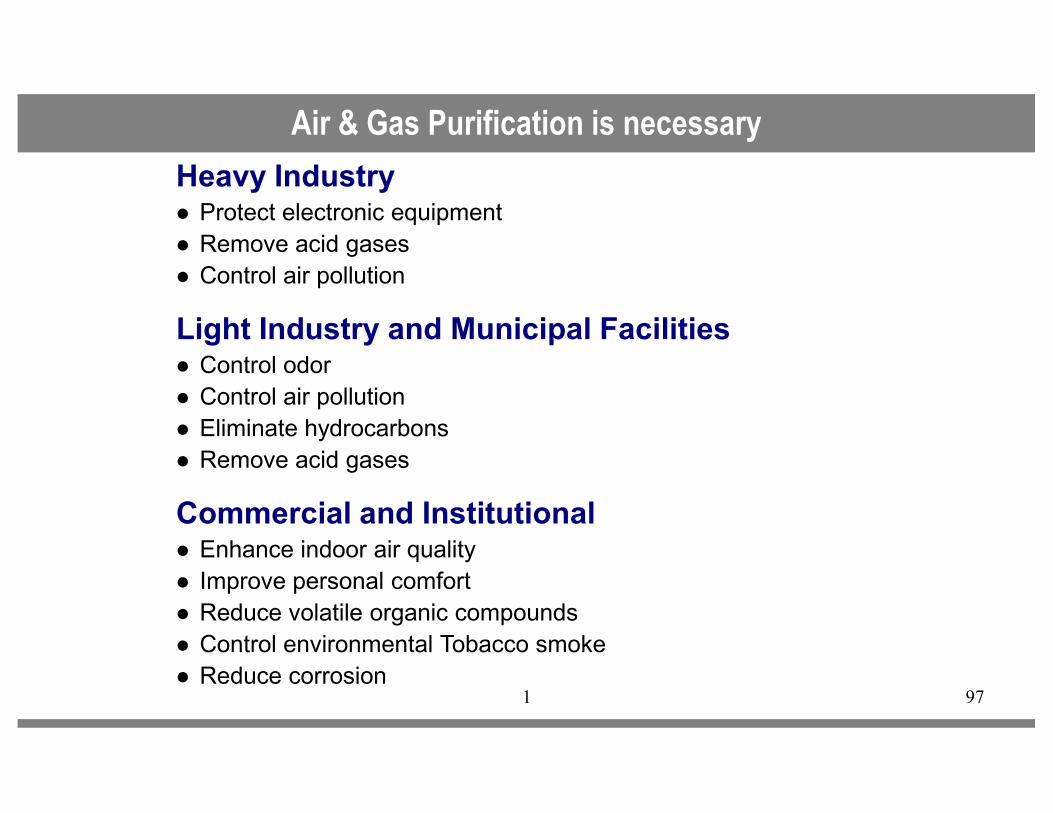
Heavy Industry� Protect electronic equipment� Remove acid gases� Control air pollution
Light Industry and Municipal Facilities� Control odor� Control air pollution
Air & Gas Purification is necessary
1 97
� Control air pollution� Eliminate hydrocarbons� Remove acid gases
Commercial and Institutional� Enhance indoor air quality� Improve personal comfort� Reduce volatile organic compounds� Control environmental Tobacco smoke� Reduce corrosion

There are three methods of control for gas contaminants :
• Source control : Removal of source [s] of the contaminants –not possible always.
• Ventilation control : Introduce clean air into the spaces todilute the level of the contaminants within acceptable limits.
• Removal control : Control contaminants by either physical or
Methods of Control
1 98
• Removal control : Control contaminants by either physical orchemical means.
THIS IS WHAT WE DO.
"To achieve an acceptable level of contaminant control,
economically, a combined strategy of dilution and removal
control may be required ".

The Air & Gas Purification helps to filter gaseous contaminants like SO2, H2S etc. from air
Air & Gas Purification
1 99

�Relative Humidity : <60% at <6% change per hour
�Temperature : 17-24°°°°C + 3°°°°C change
�Room pressure; 12.5 - 25 pa
Recommended Room Environmental Standards
1 100
�Corrosion rates:
Copper <10 angstroms/24 hours<300 angstroms/Month
Silver <10 angstrom/24hours<300 angstrom/Month

Our Presentation Today
� Indoor Air Quality Concept
� Fresh Air Energy Design Dilemma
� Energy Recovery Options
� Heat Recovery Wheel Evaluation Parameters
� Heat Recovery Wheel Applications Green Buildings / Hospitals
� RH Management Concerns
� DOAS Concept & Technology Options
� DOAS Integration with Parallel system / Chilled beams
� Dehumidification Technology for swimming Pools
� Commercial Air & Gas Purification Units
� Cooling Pads Air Conditioning for Dry Places
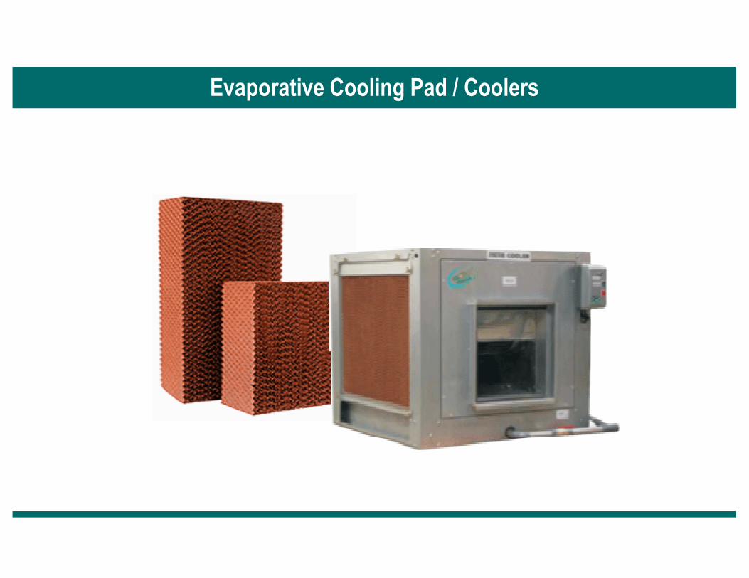
Evaporative Cooling Pad / Coolers

� Psychrometrically referred as Adiabatic Saturation Process
� Adding water in vapor form to the air cools the air
� Evaporation process is used to cool the air passing through a wetted cooling media.
TECHNICAL PARAMETERS
� Wet Bulb Depression : is the difference between Dry bulb and Wet bulb
Evaporative Cooling Process
� Wet Bulb Depression : is the difference between Dry bulb and Wet bulb temperatures
� Evaporation rate : The rate at which water is absorbed into the air passing through the cooling media , measured in gallons of water per minute.
� Cooling Efficiency : The percent of temperature drop across the cooling media compared to the wet bulb Depression .Also termed Saturation Efficiency as it refers to amount of moisture packed in the air

Methods of Cooling
� Fogging Systems/ Spray Type Systems
� Evaporative Cooling Pads
EVAPORATIVE COOLING PADS
Evaporative Cooing Pads are called so because water gets evaporated when itcomes in contact with the air. It withdraws the Sensible heat of air as the heat ofevaporation. This process in turn brings down the temperature of air. The airtemperature thus approaches the WBT of the incoming air.
The functioning of Evaporative Pad is very simple. The air is allowed to passthrough the pad and at the same time water is added at the top throughdistributor.
Advantages of Evaporative Cooling :
- Low Pay back period
- Low Operational costs
- Low Maintenance costs
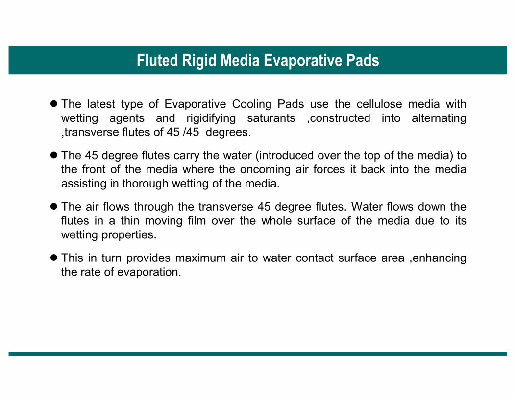
Fluted Rigid Media Evaporative Pads
� The latest type of Evaporative Cooling Pads use the cellulose media withwetting agents and rigidifying saturants ,constructed into alternating,transverse flutes of 45 /45 degrees.
� The 45 degree flutes carry the water (introduced over the top of the media) tothe front of the media where the oncoming air forces it back into the mediaassisting in thorough wetting of the media.
� The air flows through the transverse 45 degree flutes. Water flows down theflutes in a thin moving film over the whole surface of the media due to itswetting properties.
� This in turn provides maximum air to water contact surface area ,enhancingthe rate of evaporation.

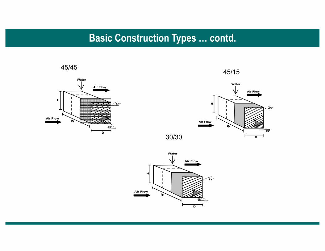
Basic Construction Types
The unique air-to-liquid contact media consisting of corrugated sheets ofwettable, strong cellulose material impregnated specially with decay –resisting chemicals. The impregnation also makes the materials stiff enoughto make it Self-supporting and protects the media against decompositioncaused by water and air very effectively.
FLUTE HEIGHT
� Due to corrugation each sheet of the pad looks like sinusoidal wave, almostsemi circular in nature double the radius of each semicircle is called FluteHeight.
� Types – Cooling pad is broadly classified into two types on the basis of FluteHeight. Generally two types of flute height are available in the market e.g.5MM & 7MM. These pads are further subdivided on the basis of flute angles.
Air Flow
Air Flow
W
H
Water
45°
45°
Air Flow
Air Flow
W
H
Water
45°
45/45 45/15
Basic Construction Types … contd.
D
45° W
D
15°
Air Flow
Air Flow
W
D
H
Water
30°
30°
30/30
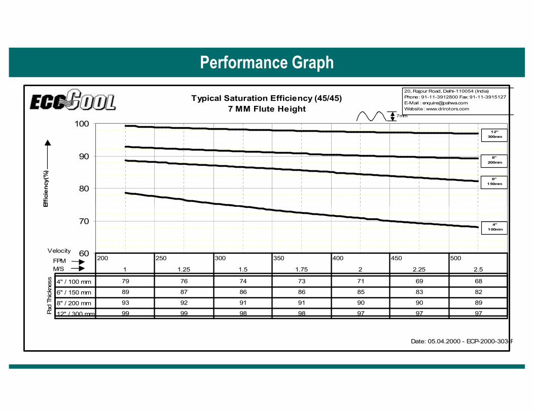
Typical Saturation Efficiency (45/45)7 MM Flute Height
80
90
100
Efficiency(%)
20, Rajpur Road, Delhi-110054 (India)
Phone : 91-11-3912800 Fax: 91-11-3915127
E-Mail : [email protected]
Website : www.drirotors.com
6"
150mm
8"
200mm
12"
300mm
7mm
Performance Graph
60
70
Efficiency(%)
4" / 100 mm 79 76 74 73 71 69 68
6" / 150 mm 89 87 86 86 85 83 82
8" / 200 mm 93 92 91 91 90 90 89
12" / 300 mm 99 99 98 98 97 97 97
200 250 300 350 400 450 500
1 1.25 1.5 1.75 2 2.25 2.5
FPM
M/S
Velocity
Pad
Thic
kness
Date: 05.04.2000 - ECP-2000-303-R
4"
100mm

PIPE LINE
CHILLER
COOLING
Cooling Module
SUPPLY IN
DRAIN
COOLINGMODULE
PUMP
MODULE
MOUNTING

To further explore existing and upcoming
Desiccant Technologies in HVAC Systems
please visit our websites
www.drirotors.com
www.bryair.com

Thank You !Thank You !