ib series operating instructions - · ib series half/full step driver operating instructions ......
TRANSCRIPT

T
intelligent motion systems, inc.
Excellence in MotionTM
IB SERIESHALF/FULL STEP STEPPING MOTOR DRIVERS
IB462 IB463 IB104 IB106 IB1010
OPERATING INSTRUCTIONS
370 N. MAIN ST., PO BOX 457, MARLBOROUGH, CT 06447PH. (860) 295-6102, FAX (860) 295-6107
Internet: http://www.imshome.com, E-Mail: [email protected]
TM

The information in this book has been carefully checked and isbelieved to be accurate; however, no responsibility is assumed forinaccuracies.
Intelligent Motion Systems, Inc., reserves the right to make changeswithout further notice to any products herein to improve reliability,function or design. Intelligent Motion Systems, Inc., does not assumeany liability arising out of the application or use of any product or circuitdescribed herein; niether does it convey any license under its patentrights of others. Intelligent Motion Systems and aretrademarks of Intelligent Motion Systems, Inc.
Intelligent Motion Systems, Inc.’s general policy does not recommendthe use of its products in life support or aircraft applications wherein afailure or malfunction of the product may directly threaten life or injury.Per Intelligent Motion Systems, Inc.’s terms and conditions of sales, theuser of Intelligent Motion Systems, Inc., products in life support oraircraft applications assumes all risks of such use and indemnifiesIntelligent Motion Systems, Inc., against all damages.
TM
© 2000 by Intelligent Motion Systems, Inc.All Rights Reserved
IB Series Half/Full Step Driver Operating InstructionsRevision 05.19.2000

1
Contents
IMPORTANT! READ THIS FIRST! ........................................................... 5The Product Manual ...................................................................................... 5Connecting the IB Series Driver to Your System .......................................... 5Notes and Warnings ..................................................................................... 6
Part I: General InformationSection 1.1: Introduction to the IB Series Drivers ................................. 8
Features and Benefits ................................................................................... 9Section 1.2: Theory of Operation ........................................................ 11
Section Overview ......................................................................................... 11Circuit Operation ......................................................................................... 11Output Wave Sequences ............................................................................12Timing .........................................................................................................13
Section 1.3: Selecting a Power Supply ............................................... 14Section Overview .........................................................................................14Selecting a Power Supply ...........................................................................14Recommended Wiring ................................................................................16AC Line Filtering ..........................................................................................17
Section 1.4: Motor Selection and Connection .................................... 18Section Overview .........................................................................................18Selecting a Motor .........................................................................................18Motor Wiring ................................................................................................21
Section 1.5: Interfacing to the IB Series Drive .................................... 25Section Overview .........................................................................................25Layout and Interface Guidelines .................................................................25Pin Assignment and Description ................................................................26Basic Connections ......................................................................................27Interfacing Motor Power (+V) .......................................................................27Interfacing the Logic Inputs .........................................................................28Controlling the Output Current ....................................................................30
Section 1.6: Troubleshooting .............................................................. 32Section Overview .........................................................................................32Basic Troubleshooting ................................................................................32Problem Symptoms and Possible Causes ...............................................32Contacting Application Support ..................................................................34The IMS Web Site ........................................................................................35Returning Your Product to IMS ....................................................................35
Part 2: Hardware ReferenceSection 2.1: IB462 ................................................................................. 38
Section Overview .........................................................................................38Mechanical Specifications ..........................................................................38Electrical Specifications ..............................................................................39Thermal Specifications ...............................................................................39

2
Current Adjust Resistor Values ..................................................................40Recommended IMS Power Supplies .........................................................41Recommended IMS Motors ........................................................................41Options and Accessories ...........................................................................42
Section 2.2: IB463 ................................................................................. 43Section Overview .........................................................................................43Mechanical Specifications ..........................................................................43Electrical Specifications ..............................................................................44Thermal Specifications ...............................................................................44Current Adjust Resistor Values ..................................................................45Recommended IMS Power Supplies .........................................................46Recommended IMS Motors ........................................................................46Options and Accessories ...........................................................................47
Section 2.3: IB104 ................................................................................. 48Section Overview .........................................................................................48Mechanical Specifications ..........................................................................48Electrical Specifications ..............................................................................49Thermal Specifications ...............................................................................49Current Adjust Resistor Values ..................................................................50Recommended IMS Power Supplies .........................................................51Recommended IMS Motors ........................................................................52Options and Accessories ...........................................................................52
Section 2.4: IB106 ................................................................................. 53Section Overview .........................................................................................53Mechanical Specifications ..........................................................................53Electrical Specifications ..............................................................................54Thermal Specifications ...............................................................................54Current Adjust Resistor Values ..................................................................55Recommended IMS Power Supplies .........................................................56Recommended IMS Motors ........................................................................57Options and Accessories ...........................................................................57
Section 2.5: IB1010 ............................................................................... 58Section Overview .........................................................................................58Mechanical Specifications ..........................................................................58Electrical Specifications ..............................................................................59Thermal Specifications ...............................................................................59Current Adjust Resistor Values ..................................................................60Recommended IMS Power Supplies .........................................................61Recommended IMS Motors ........................................................................61Options and Accessories ...........................................................................62
Appendix A: OPT140 ............................................................................ 63Optional Interface Board .............................................................................63
Appendix B: Cooling Solutions .......................................................... 67H-4X Heat Sink ............................................................................................67H-100 Heat Sink ..........................................................................................67Thermal Pads .............................................................................................68
Appendix C: Miscellaneous Accessories ............................................ 70

3
List of FiguresFigure 1.2.1 IB Series Block Diagram .................................................... 11Figure 1.2.2 Normal Mode Phase Sequence .........................................12Figure 1.2.3 Wave Mode Phase Sequence ............................................13Figure 1.2.4 Half Step Mode Phase Sequence ......................................13Figure 1.2.5 Timing .................................................................................13Figure 1.4.1 Per Phase Winding Inductance ..........................................20Figure 1.4.2 8 Lead Motor Series Connection ........................................22Figure 1.4.3 8 Lead Motor Parallel Connection ......................................22Figure 1.4.4 6 Lead Motor Half Coil Connection ....................................23Figure 1.4.5 6 Lead Motor Full Coil Connection .....................................23Figure 1.4.6 4 Lead Motor Connection ...................................................24Figure 1.5.1 Basic Connections .............................................................27Figure 1.5.2 Opto-coupler Input Circuit ...................................................28Figure 1.5.3 TTL Interface .......................................................................29Figure 1.5.4 Open Collector Interface .....................................................29Figure 1.5.5 74HC/54HC/74HCT/54HCT Interface ................................30Figure 1.5.6 Current Adjust Resistor Placement ....................................30Figure 1.5.7 Switching Phase Currents ..................................................31Figure 1.5.8 Isolated Switching of Phase Currents ................................31Figure 2.1.1 IB462 Dimensions ..............................................................38Figure 2.2.1 IB463 Dimensions ..............................................................43Figure 2.3.1 IB104 Dimensions ..............................................................48Figure 2.4.1 IB106 Dimensions ..............................................................53Figure 2.5.1 IB1010 Dimensions ............................................................58Figure A.1 PT-140 Dimensions ...........................................................63Figure A.2 OPT-140 Placement ...........................................................65Figure A.3 OPT-140 Schematic Representation .................................65Figure B.1 H-4X Heat Sink ....................................................................67Figure B.2 H-100X Heat Sink ...............................................................68
4
List of TablesTable 1.4.1 Motor Connections ................................................................21Table 1.5.1 Pin Assignment and Description ..........................................26Table 2.1.1 IB462 Electrical Specifications ..............................................39Table 2.1.2 IB462 Thermal Specifications ...............................................39Table 2.1.3 IB462 Current Adjust Resistor Values ..................................40Table 2.1.4 IP402 Power Supply Specifications ......................................41Table 2.2.1 IB463 Electrical Specifications ..............................................44Table 2.2.2 IB463 Thermal Specifications ...............................................44Table 2.2.3 IB463 Current Adjust Resistor Values ..................................45Table 2.2.4 IP404 Power Supply Specifications ......................................46Table 2.3.1 IB104 Electrical Specifications ..............................................49Table 2.3.2 IB104 Thermal Specifications ...............................................49Table 2.3.3 IB104 Current Adjust Resistor Values ..................................50Table 2.3.4 IP804 Power Supply Specifications ......................................51Table 2.3.5 ISP300-7 Power Supply Specifications .................................51Table 2.4.1 IB106 Electrical Specifications ..............................................54Table 2.4.2 IB106 Thermal Specifications ...............................................54Table 2.4.3 IB106 Current Adjust Resistor Values ..................................55Table 2.4.4 IP804 Power Supply Specifications ......................................56Table 2.4.4 ISP300-7 Power Supply Specifications .................................56Table 2.5.1 IB1010 Electrical Specifications ............................................59Table 2.5.2 IB1010 Thermal Specifications .............................................59Table 2.5.3 IB1010 Current Adjust Resistor Values ................................60Table 2.5.4 IP806 Power Supply Specifications ......................................61Table A.1 OPT-140 Pin Configuration ...................................................66

5
IMPORTANT! READ THIS FIRST!
The P r o du c t Manua l
U s i n g T h i s M a n u a l
This manual is divided into two parts:
Part 1 is General Information, which covers details common to the entireIB Series of products such as operational theory, connection and interfaceinstructions, and troubleshooting.
Part 2 is Hardware Reference. This part contains sections with informa-tion specific to each individual IB drive. Here you will find details such asmechanical, electrical and thermal specifications, current control resistorvalue tables and recommended power supplies and motors for each IBseries drive. Do not attempt to connect or use your drive without firstconsulting the section specific to the IB series drive you purchased!
H y p e r l i n k s
The IB series product manual in it’s electronic format (ib.pdf) can bedownloaded from the IMS website at www.imshome.com This versionincludes a hyperlink feature that allows the reader tolink from a referenced feature to a full description ofthat feature attributes and functions. Words with ahyperlink function are blue, italic and underlined andare further identifiable because the cursor changesfrom a normal pointer to a “finger” pointer whenplaced over the word.
Connecting The IB Series Driver to your System
All logic inputs are optically isolated and MUST have acurrent limiting resistor at each input.
Most regulated supplies use a voltage interrupt or “crow-bar” current limit. That is, when the supply senses anover-current condition, it will turn off the output voltage fora time, and then back on again. This will continue until theover-current condition is cleared. Therefore, when using aregulated power supply for drive voltage, the supply shouldprovide current sufficient enough to handle the high inrushmotor current during power-up. If it does not, the powersupply will switch into current limit and cut off regulatingvoltage to the drive. This can cause damage to the IBSeries Motor Driver! Methods that will correct this conditionare as follows:
6
No t e s a n d Wa rn i n g s
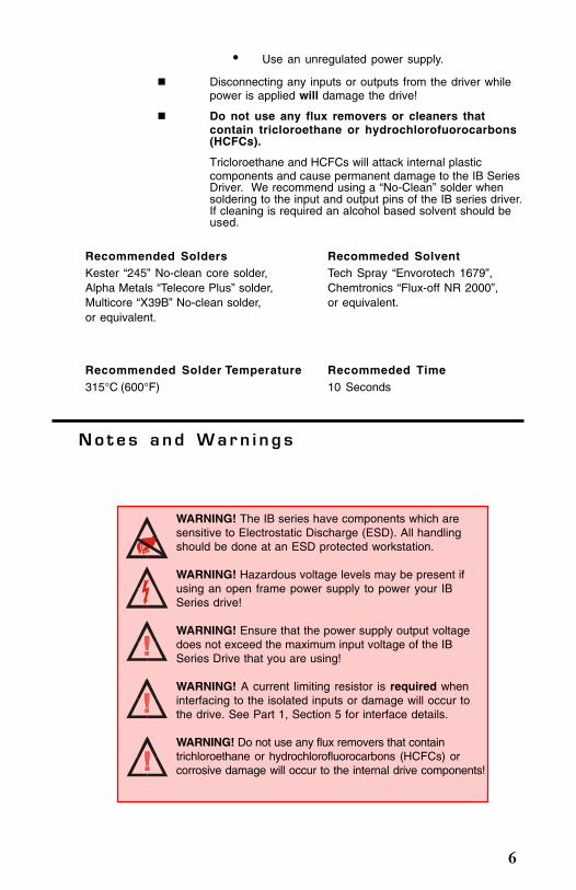
• Use an unregulated power supply.
Disconnecting any inputs or outputs from the driver whilepower is applied will damage the drive!
Do not use any flux removers or cleaners thatcontain tricloroethane or hydrochlorofuorocarbons(HCFCs).
Tricloroethane and HCFCs will attack internal plasticcomponents and cause permanent damage to the IB SeriesDriver. We recommend using a “No-Clean” solder whensoldering to the input and output pins of the IB series driver.If cleaning is required an alcohol based solvent should beused.
Recommended Solders Recommeded SolventKester “245” No-clean core solder, Tech Spray “Envorotech 1679”,Alpha Metals “Telecore Plus” solder, Chemtronics “Flux-off NR 2000”,Multicore “X39B” No-clean solder, or equivalent.or equivalent.
WARNING! The IB series have components which aresensitive to Electrostatic Discharge (ESD). All handlingshould be done at an ESD protected workstation.
WARNING! Hazardous voltage levels may be present ifusing an open frame power supply to power your IBSeries drive!
WARNING! Ensure that the power supply output voltagedoes not exceed the maximum input voltage of the IBSeries Drive that you are using!
WARNING! A current limiting resistor is required wheninterfacing to the isolated inputs or damage will occur tothe drive. See Part 1, Section 5 for interface details.
WARNING! Do not use any flux removers that containtrichloroethane or hydrochlorofluorocarbons (HCFCs) orcorrosive damage will occur to the internal drive components!
Recommended Solder Temperature Recommeded Time315°C (600°F) 10 Seconds

7
GeneralInformation
Part I
Section 1.1–Introduction
Section 1.2–Theory of Operation
Section 1.3–Selecting a Power Supply
Section 1.4–Selecting a Motor
Section 1.5–Interfacing
Section 1.6–Troubleshooting

8
S e c t i o n 1 . 1Introduction to the IB Series Drivers
I B S e r i e s H a l f / F u l l S t e p D r i v e r s
The IB series of miniature high performance stepper motor drives aredesigned for today’s quality minded, price sensitive market. The 40 voltseries has a +12 to +40 VDC input voltage, up to 3.5 Amps per phasedrive current and a maximum step frequency of 40kHz. The 80V serieshas a +24 to +80 VDC input voltage, up to a powerful 9 Amps per phaseof drive current and a maximum step frequency of 250kHz. All of thesedrives feature pin compatibility, optically isolated logic inputs, and a 20kHz chopping rate to reduce noise. In addition, all these drives are singlesupply.
T h e 4 0 V L i n e o f I B D r i v e s
I B462
The IB462 packs a powerful 160 Watts into less than 3 cu. in. This driveoperates from +12 to +40VDC and effortlessly outputs 2 Amps per phase.This high voltage allows for greater speeds at higher torque without having toresort to expensive drives or larger motors.
The high efficiency of the IB462 chopper drive along with its miniaturesize make it ideally suited to replace the less efficient L/R drives. Inaddition, the low cost and off-the-shelf availability of the IB462 permitsan immediate, cost effective solution to an in-house design.
I B463
The IB463 has an output capability of up to 3.5 Amps per phase and,while it operates at the same voltage range as the IB462, it can deliver 1.4times more power. This equates to 230 Watts of power in a package thatonly requires 3.6 cubic inches of real estate.
The IB463 is ideal for those applications requiring more power, but wheresize and cost are still important factors.
T h e 8 0 V L i n e o f I B D r i v e s
The IB104, 106 and 1010 use MOSFET technology to achieve high powerfrom a miniature package. These drives are designed to get maximumperformance from larger, higher torque motors. This type of performanceis required for today’s most demanding applications.
9
F e a t u r e s a n d B en e f i t s
G e n e r a l F e a t u r e s
Very Low Cost.
Single Supply.
On-Board Phase Logic.
Isolated Inputs.
PC Board or Chassis Mountable.
Extremely Small Size.
20 kHz Chopping Rate.
Full or Half Step.
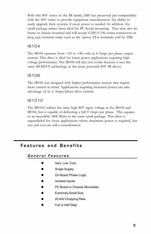
With this 80V series of the IB family, IMS has preserved pin compatibilitywith the 40V series to provide equipment manufacturer’s the ability toeasily upgrade their systems if more power is needed. In addition, thesmall package makes them ideal for PC board mounting. They may also beframe or chassis mounted and will accept 0.200/0.196 center connectors orplug type terminal strips such as the option TS-6 terminals sold by IMS.
I B104
The IB104 operates from +24 to +80 volts at 4 Amps per phase outputcurrent. This drive is ideal for lower power applications requiring highvoltage performance. The IB104 will also run cooler because it uses thesame MOSFET technology as the more powerful 80V IB drives.
I B106
The IB106 was designed with higher performance motors that requiremore current in mind. Applications requiring increased power can takeadvantage of its 6 Amps/phase drive current.
I B1010
The IB1010 utilizes the same high 80V input voltage as the IB104 andIB106, but is capable of delivering a full 9 Amps per phase. This equatesto an incredible 1800 Watts in the same small package. This drive isunparalleled for those applications where maximum power is required, butsize and cost are still a consideration.
10
P r o d u c t S p e c i f i c F e a t u r e s
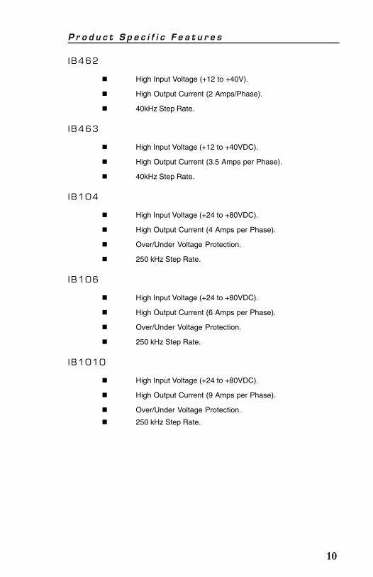
I B462
High Input Voltage (+12 to +40V).
High Output Current (2 Amps/Phase).
40kHz Step Rate.
I B463
High Input Voltage (+12 to +40VDC).
High Output Current (3.5 Amps per Phase).
40kHz Step Rate.
I B104
High Input Voltage (+24 to +80VDC).
High Output Current (4 Amps per Phase).
Over/Under Voltage Protection.
250 kHz Step Rate.
I B106
High Input Voltage (+24 to +80VDC).
High Output Current (6 Amps per Phase).
Over/Under Voltage Protection.
250 kHz Step Rate.
I B1010
High Input Voltage (+24 to +80VDC).
High Output Current (9 Amps per Phase).
Over/Under Voltage Protection.
250 kHz Step Rate.

11
S e c t i o n 1 . 2T h e o r y o f O p e r a t i o n
S e c t i o n O v e r v i e w
This section will cover the circuit operation for the IB series drives.
Circuit Operation.
Output Wave Sequences.
Timing.
C i r c u i t O p e r a t i o n
The IB series drives are bipolar chopping stepper motor drives. Theyreceive step clock, direction and mode signals from the system controllerand generate constant phase currents which are adjustable in magnitude.
The principal functions are: a translator which generates the motor phasesequences, a dual PWM chopper circuit which regulates the current in themotor windings and a power stage to drive the motor. The translatorgenerates three different sequences selected by the half/full step input.These are normal (two phases energized), wave drive (one phase energized)
Figure 1.2.1: IB Series Block Diagram
TRANS LATORDRIVE LO GIC
+5 VD C+5v
REGULATOR
OS CILLATO R
Q
S R
Q
S R-
+
-
+
+5 VDC
+5 VDC
Q
C
D
ENABLE P IN 1
LOG IC GR OU ND P IN 2
H ALF / FU LL S TEP PIN 3
STEP C LO CK P IN 4
C W /C CW P IN 5
C UR REN T AD JU ST P IN 6
FILTER
FILTER
P IN 8 +V
PIN 12 A
PIN 11 A
PIN 10 B
PIN 9 B
PIN 7 GR O UND
OU TPUTBRIDGE
OU TPUTBRIDGE
12
and half step (alternately one phase energized/ two phases energized).
A common on-board oscillator drives the dual chopper. It supplies pulseswhich set two flip-flops. When the current in a winding reaches theprogrammed peak value a corresponding comparator resets its flip-flop,shutting down the output stage until the next oscillator pulse comes along.
Because the windings in the motor store energy, current will continue toflow through the windings during the off period. The peak current forboth windings is programmed by the current adjust input.
The output stage consists of dual full bridge drivers. The IB Series drivescan be disabled by a logic HIGH signal on the enable input. Ultra fastrecovery fly-back rectifiers are used to improve efficiency and help reducenoise.
Ou t p u t Wav e S equ en c e s
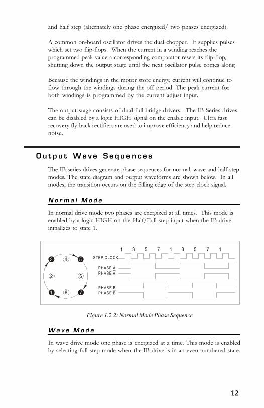
The IB series drives generate phase sequences for normal, wave and half stepmodes. The state diagram and output waveforms are shown below. In allmodes, the transition occurs on the falling edge of the step clock signal.
N o r m a l M o d e
In normal drive mode two phases are energized at all times. This mode isenabled by a logic HIGH on the Half/Full step input when the IB driveinitializes to state 1.
W a v e M o d e
In wave drive mode one phase is energized at a time. This mode is enabledby selecting full step mode when the IB drive is in an even numbered state.
Figure 1.2.2: Normal Mode Phase Sequence
1
3 5
7
2
4
6
8
1 3 5 7 1 3 5 7 1
STEP CLOCK
PHASE A
PHASE B
PHASE A
PHASE B
13
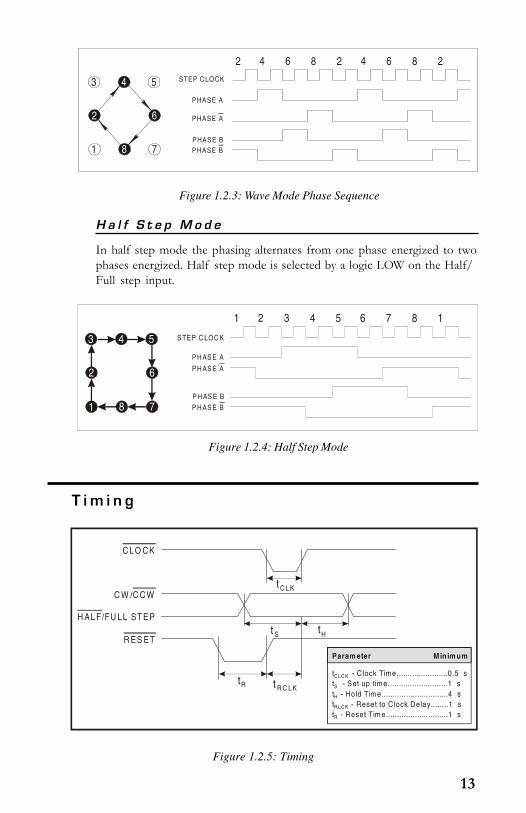
H a l f S t e p M o d e
In half step mode the phasing alternates from one phase energized to twophases energized. Half step mode is selected by a logic LOW on the Half/Full step input.
T i m i n g
Figure 1.2.5: Timing
Figure 1.2.3: Wave Mode Phase Sequence
1
3 5
7
2
4
6
8
2 4 6 8 2 4 6 8 2
STEP C LOCK
PHASE A
PHASE B
PHASE A
PHASE B
Figure 1.2.4: Half Step Mode
1
3 5
7
2
4
6
8
1 2 3 4 5 6 7 8 1
S TEP C LOC K
P H AS E A
P H AS E B
P H AS E A
P H AS E B
t C L K
t S tH
tR t R C LK
C LO CK
C W /C C W
H AL F/FU LL ST E P
R ES ET
Param eter M in im um
t - C lock Time.......................0.5 st - Set up time...........................1 st - Hold Tim e..............................4 st - Reset to C lock Delay........1 s
C LC K
S
H
R LC K
t - Reset Tim e............................1 sR
14
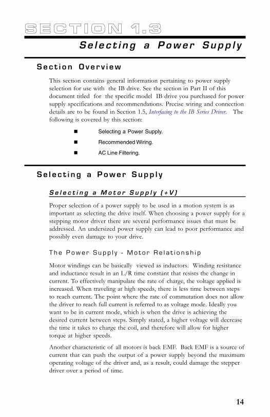
S e c t i o n 1 . 3Se l e c t i n g a P owe r S upp l y
S e c t i o n O v e r v i e w
This section contains general information pertaining to power supplyselection for use with the IB drive. See the section in Part II of thisdocument titled for the specific model IB drive you purchased for powersupply specifications and recommendations. Precise wiring and connectiondetails are to be found in Section 1.5, Interfacing to the IB Series Driver. Thefollowing is covered by this section:
Selecting a Power Supply.
Recommended Wiring.
AC Line Filtering.
Se l e c t i n g a P owe r S upp l y
S e l e c t i n g a M o t o r S u p p l y ( + V )
Proper selection of a power supply to be used in a motion system is asimportant as selecting the drive itself. When choosing a power supply for astepping motor driver there are several performance issues that must beaddressed. An undersized power supply can lead to poor performance andpossibly even damage to your drive.
T h e P o w e r S u p p l y - M o t o r R e l a t i o n s h i p
Motor windings can be basically viewed as inductors. Winding resistanceand inductance result in an L/R time constant that resists the change incurrent. To effectively manipulate the rate of charge, the voltage applied isincreased. When traveling at high speeds, there is less time between stepsto reach current. The point where the rate of commutation does not allowthe driver to reach full current is referred to as voltage mode. Ideally youwant to be in current mode, which is when the drive is achieving thedesired current between steps. Simply stated, a higher voltage will decreasethe time it takes to charge the coil, and therefore will allow for highertorque at higher speeds.
Another characteristic of all motors is back EMF. Back EMF is a source ofcurrent that can push the output of a power supply beyond the maximumoperating voltage of the driver and, as a result, could damage the stepperdriver over a period of time.

15
T h e P o w e r S u p p l y - D r i v e r R e l a t i o n s h i p
The IB series driver is very current efficient as far as the power supply isconcerned. Once the motor has charged one or both windings of themotor, all the power supply has to do is replace losses in the system. Thecharged winding acts as an energy storage in that the current will recirculatewithin the bridge, and in and out of each phase reservoir. This results in aless than expected current draw on the supply.
Stepping motor drivers are designed with the intention that a user’s powersupply output will ramp up to greater or equal to the minimum operatingvoltage. The initial current surge is quite substantial and could damage thedriver if the supply is undersized. The output of the power supply couldfall below the operating range of the driver upon a current surge if it isundersized. This could cause the power supply to start oscillating in andout of the voltage range of the driver and result in damage to either thesupply, the driver, or both. There are two types of supplies commonlyused, regulated and unregulated, both of which can be switching or linear.All have their advantages and disadvantages.
R e g u l a t e d v s . U n r e g u l a t e d
An unregulated linear supply is less expensive and more resilient tocurrent surges, however, the voltage decreases with increasing currentdraw. This can cause problems if the voltage drops below the workingrange of the drive. Also of concern are the fluctuations in line voltage.This can cause the unregulated linear supply to be above or below theanticipated or acceptable voltage.
A regulated supply maintains a stable output voltage, which is good forhigh speed performance. They are also not bothered by line fluctuations,however, they are more expensive. Depending on the current regulation,a regulated supply may crowbar or current clamp and lead to an oscilla-tion that may cause damage to the driver and/or power supply. BackEMF can cause problems for regulated supplies as well. The currentregeneration may be too large for the regulated supply to absorb. Thiscould lead to an over voltage condition which could damage the outputcircuitry of the IB driver.
Non IMS switching power supplies and regulated linear supplies withover-current protection are not recommended because of their inability tohandle the surge currents inherit in stepping motor systems.
WARNING! Do not connect or disconnect motor or powerleads with power applied!

16
R e c o m m e n d e d W i r i n g
R u l e s o f W i r i n g a n d S h i e l d i n g
Noise is always present in a system that involves high power and smallsignal circuitry. Regardless of the power configuration used for yoursystem, there are some wiring and shielding rules that should be followedto keep the signal-to-noise ratio as small as possible.
R u l e s o f W i r i n g
Power supply and motor wiring should be shieldedtwisted pairs run separately from signal carrying wires.
A minimum of 1 twist per inch is recommended.
Motor wiring should be shielded twisted pairs using 20-gauge wire or, for distance greater than 5 feet, 18 gaugeor better.
Power ground return should be as short as possible toestablished ground.
Power supply wiring should be shielded twisted pairs.Use 18 gauge wire if load is less than 4 amps, or 16gauge for more than 4 amps.
Do not “daisy-chain” power wiring to system components.
R u l e s o f S h i e l d i n g
The shield must be tied to zero-signal reference potential.In order for shielding to be effective it is necessary for thesignal to be earthed or grounded.
Do not assume that earth ground is true earth ground.Depending on the distance to the main power cabinet itmay be necessary to sink a ground rod at a criticallocation.
The shield must be connected so that shield currents drainto signal-earth connections.
The number of separate shields required in a system isequal to the number of independent signals beingprocessed plus one for each power entrance.
The shield should be tied to a single point to preventground loops.
A second shield can be used over the primary shield,however, the second shield is tied to ground at both ends.
17
R e c o m m e n d e d P o w e r S u p p l y C a b l e s
Power supply cables must not run parallel to logic level wiring as noise willbe coupled onto the logic signals from the power supply cables. If morethan one driver is to be connected to the same power supply, run separatepower and ground leads to each driver from the power supply. Thefollowing Belden cables (or equivalent) are recommended for use with theIB series drive.
Twisted Pair Jacketed
<4 Amps DC ......................... Belden part# 9740 or equivalent 18 AWG>4 Amps DC ......................... Belden part# 8471 or equivalent 16 AWG
AC L i n e F i l t e r i n g
The output voltage of an unregulated power supply will vary with the ACinput applied. It is recommended that an AC line filter be used to preventdamage to the IB series drive due to a lightning strike or power surge.
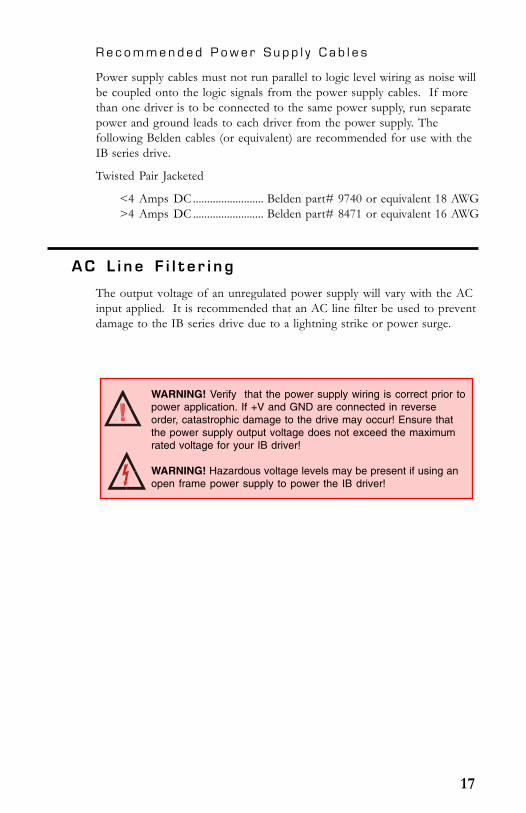
WARNING! Verify that the power supply wiring is correct prior topower application. If +V and GND are connected in reverseorder, catastrophic damage to the drive may occur! Ensure thatthe power supply output voltage does not exceed the maximumrated voltage for your IB driver!
WARNING! Hazardous voltage levels may be present if using anopen frame power supply to power the IB driver!

18
S e c t i o n 1 . 4Moto r S e l e c t i o n a n d C onne c t i o n
S e c t i o n O v e r v i e w
This section covers the motor configurations for the IB series drive, as wellas general information concerning motor selection and connection. Forspecific motor recommendations see the section in Part II of this docu-ment pertaining to the model IB drive which you purchased.
Selecting a Motor.
Motor Wiring.
Connecting the Motor.
Se l e c t i n g a Mo t o r
When selecting a stepper motor for your application there are severalfactors that need to be taken into consideration.
How will the motor be coupled to the load?
How much torque is required to move the load?
How fast does the load need to move or accelerate?
What degree of accuracy is required when positioning theload?
While determining the answers to these and other questions is beyond thescope of this document, they are details that you must know in order toselect a motor that is appropriate for your application. These details willeffect everything from the power supply voltage to the type and wiringconfiguration of your stepper motor, as well as the current and half/fullstep settings of your IB series drive.
T y p e s a n d C o n s t r u c t i o n o f S t e p p i n g M o t o r s
The stepping motor, while classed as a DC motor, is actually an AC motorthat is operated by trains of pulses. Though it is called a “stepping motor”it is in reality a polyphase synchronous motor. This means it has multiplephases wound in the stator and the rotor is dragged along in synchronismwith the rotating magnetic field. The IB series drivers are designed to workwith the following types of stepping motors:
1) Permanent Magnet (PM).
2) Hybrid Stepping Motors.
19
Hybrid stepping motors combine the features of the PM stepping motorswith the features of another type of stepping motor called a VariableReluctance Motor (VR). A VR motor is a low torque and load capacitymotor typically used in instrumentation. The IB series drivers cannot beused with VR motors as they have no permanent magnet.
On hybrid motors the phases are wound on toothed segments of thestator assembly. The rotor consists of a permanent magnet with a toothedouter surface which allows precision motion accurate to within ± 3 percent. Hybridstepping motors are available with step angles varying from 0.45° to 15°, with 1.8°being the most commonly used. Torque capacity in hybrid steppers range from 5 -8000 ounce-inches. Because of their smaller step angles, hybrid motors have ahigher degree of suitability in applications where precise load positioning andsmooth motion is required.
S i z i n g a M o t o r f o r Yo u r S y s t e m
The IB series drivers are bipolar drivers which work equally well with both bipolarand unipolar motors (i.e. 8 and 4 lead motors, and 6 lead center tapped motors).
To maintain a given set motor current the IB drive chops the voltage using aconstant 20kHz chopping frequency and a varying duty cycle. Duty cycles thatexceed 50% can cause unstable chopping. This characteristic is directly related to themotor’s winding inductance. In order to avoid this situation, it is necessary tochoose a motor with a low winding inductance. The lower the winding inductance,the higher the step rate possible.
Wind ing I nduc tance
Since the IB drive is a constant current source, it is not necessary to use a motor thatis rated at the same voltage as the supply voltage. What is important is that thedrive is set to the motor’s rated current. Precise current control settings areexplained in the sections of Part II of this document that pertain to the model IBdrive which you purchased.
As was discussed in the previous section, Selecting a Power Supply , the higher thevoltage used the faster the current can flow through the motor windings. This inturn means a higher step rate, or motor speed. Care should be taken not to exceedthe maximum voltage of the driver. Therefore, in choosing a motor for a systemdesign, the best performance for a specified torque is a motor with the lowestpossible winding inductance used in conjunction with highest possible drivervoltage.
The winding inductance will determine the motor type and wiring configurationbest suited for your system. While the equation used to size a motor for yoursystem is quite simple, several factors fall into play at this point.
The winding inductance of a motor is rated in milliHenrys(mH) per phase. Theamount of inductance will depend on the wiring configuration of the motor.
20
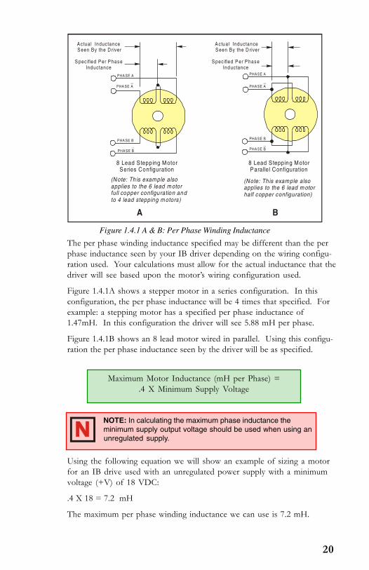
Figure 1.4.1 A & B: Per Phase Winding Inductance
The per phase winding inductance specified may be different than the perphase inductance seen by your IB driver depending on the wiring configu-ration used. Your calculations must allow for the actual inductance that thedriver will see based upon the motor’s wiring configuration used.
Figure 1.4.1A shows a stepper motor in a series configuration. In thisconfiguration, the per phase inductance will be 4 times that specified. Forexample: a stepping motor has a specified per phase inductance of1.47mH. In this configuration the driver will see 5.88 mH per phase.
Figure 1.4.1B shows an 8 lead motor wired in parallel. Using this configu-ration the per phase inductance seen by the driver will be as specified.
Using the following equation we will show an example of sizing a motorfor an IB drive used with an unregulated power supply with a minimumvoltage (+V) of 18 VDC:
.4 X 18 = 7.2 mH
The maximum per phase winding inductance we can use is 7.2 mH.
Maximum Motor Inductance (mH per Phase) =.4 X Minimum Supply Voltage
NOTE: In calculating the maximum phase inductance theminimum supply output voltage should be used when using anunregulated supply.
PHA SE A
PHA SE B
8 Lead Stepping MotorSeries Configuration
8 Lead Stepping MotorParallel Configuration
PHA SE A
PHA SE A
PHA SE BPHA SE B
PHA SE A
PHA SE B
(Note: Th is example alsoapplies to the 6 lead m otorfull copper configuration and to 4 lead stepping m otors)
(Note: Th is example alsoapplies to the 6 lead m otorhalf copper configuration)
S pec ified P er P has eInductance
S pec ified P er P has eInductance
A ctual Inductance S een By the D river
A ctual Inductance S een By the D river
A B

21
NOTE: The physical direction of the motor with respect to thedirection input will depend upon the connection of the motorwindings. To switch the direction of the motor with respect tothe direction input, switch the wires on either phase A orphase B outputs.
WARNING! Do not connect or disconnect motor or powerleads with power applied!
M o t o r W i r i n g
As with the power supply wiring, motor wiring should be run separatelyfrom logic wiring to minimize noise coupled onto the logic signals. Motorcabling exceeding 1 foot in length should be shielded twisted pairs toreduce the transmission of EMI (ElectroMagnetic Interference) which canlead to rough motor operation and poor system performance overall. For
more information on wiring and shielding, please refer to Rules of Wiringand Shielding in Section 1.3 of this manual.
Recommended motor cables:
Dual twisted pair shielded (separate shields)
< 4A RMS per phase current .......... Belden Part# 9368 or equivalent 18 AWG.> 4A RMS per phase current .......... Belden Part# 1492A or equivalent 16 AWG.
When using a bipolar motor, the motor must be within 100 feet of thedrive.
Table 1.4.1: Motor Connections
Conne c t i n g t h e Mo t o r
The motor leads are connected to the following connector pins:
Phase Connector Pin
Phase A ................................................................................... 12Phase A ................................................................................... 11Phase B ................................................................................... 10Phase B .................................................................................... 9
22
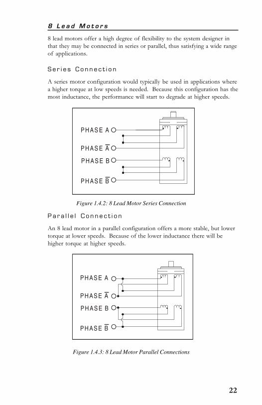
P a r a l l e l C o n n e c t i o n
An 8 lead motor in a parallel configuration offers a more stable, but lowertorque at lower speeds. Because of the lower inductance there will behigher torque at higher speeds.
Figure 1.4.3: 8 Lead Motor Parallel Connections
Figure 1.4.2: 8 Lead Motor Series Connection
8 L e a d M o t o r s
8 lead motors offer a high degree of flexibility to the system designer inthat they may be connected in series or parallel, thus satisfying a wide rangeof applications.
S e r i e s C o n n e c t i o n
A series motor configuration would typically be used in applications wherea higher torque at low speeds is needed. Because this configuration has themost inductance, the performance will start to degrade at higher speeds.
P H A S E A
P H A S E A
P H A S E B
P H A S E B
PH AS E A
PH AS E A
PH AS E B
PH AS E B
23
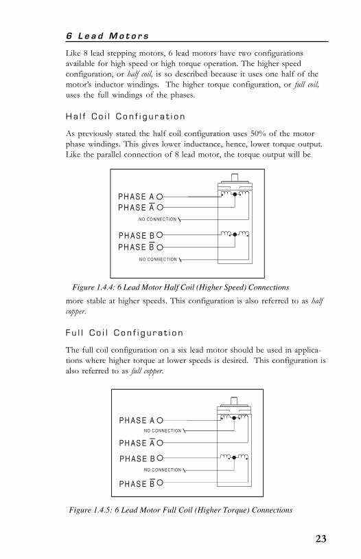
6 L e a d M o t o r s
Like 8 lead stepping motors, 6 lead motors have two configurationsavailable for high speed or high torque operation. The higher speedconfiguration, or half coil, is so described because it uses one half of themotor’s inductor windings. The higher torque configuration, or full coil,uses the full windings of the phases.
H a l f C o i l C o n f i g u r a t i o n
As previously stated the half coil configuration uses 50% of the motorphase windings. This gives lower inductance, hence, lower torque output.Like the parallel connection of 8 lead motor, the torque output will be
Figure 1.4.4: 6 Lead Motor Half Coil (Higher Speed) Connections
more stable at higher speeds. This configuration is also referred to as halfcopper.
F u l l C o i l C o n f i g u r a t i o n
The full coil configuration on a six lead motor should be used in applica-tions where higher torque at lower speeds is desired. This configuration isalso referred to as full copper.
Figure 1.4.5: 6 Lead Motor Full Coil (Higher Torque) Connections
P H A S E A
N O CO NNEC TION
N O CO NNEC TION
P H A S E A
P H A S E BP H A S E B
PH AS E ANO C ONNECTION
NO C ONNECTION
PH AS E A
PH AS E B
PH AS E B

24
4 L e a d M o t o r s
4 lead motors are the least flexible but easiest to wire. Speed and torquewill depend on winding inductance.
Figure 1.4.6: 4 Lead Motor Connections
PH AS E A
PH AS E A
PH AS E B
PH AS E B

25
S e c t i o n 1 . 5I n t e r f a c i n g t o t h e I B S e r i e s D r i v e
S e c t i o n O v e r v i e w
The IB series drive may be incorporated directly in the user’s printed circuitboard. It may also be chassis mounted and interfaced to using eithersoldered wire connection or the optional plug on terminal strips (IMS PNTS-6). In order to operate, the IB drive must have the following connec-tions
Motor Power (+V).
Motor.
Logic Interface (Step Clock, Direction).
The section also contains pin assignment and description, and sample logicand current adjust interface circuit examples.
L a y o u t a n d I n t e r f a c e Gu i d e l i n e s
Logic level signals should not run parallel to motor phase signals. Themotor phase signals will couple noise onto the logic level signals. This willcause rough motor motion and unreliable system operation. Motor phasesignals should be run as pairs and should be separated from other signalsby ground traces where possible
When leaving the board, motor cables should not run parallel with otherwires. Phases should be wired using twisted pairs. If motor cabling inexcess of one foot is required, motor cabling should be shielded twistedpairs to reduce the transmission of EMI. The shield must be tied to ACground at driver end only. The motor end must be left floating.
If more than one driver is connected to the power supply, separate powerand ground connections from each driver to the power supply should beused.
The power supply cables need to be a twisted pair if power is connectedfrom a source external to the board. If multiple drivers are used with anexternal power source, and it is not possible to run separate power andground connections to each driver, a low impedance electrolytic capacitorequivalent to two times the total capacitance of all driver capacitors and ofequal voltage must be placed at the power input of the board.

26
P i n A s s i g nmen t a n d De s c r i p t i o n
Table 1.5.1: Pin Assignment and Description
noitpircseDdnatnemngissAniPevirDseireSBI
#NIP NOITCNUF SLIATED
1 elbanE .delbaneerastuptuoesahpeht,WOLcigoLnehW
2 dnuorGcigoLehtrofhtapnruterehtsinipsihT.nommoClangiScigoL
dluohsnipsihtnoitalosiniatniamotredronI.stupnicigol.)dnuorGrewoP(7nipotdetcennocebton
3 tupnIpetSlluF/flaH
etatsWOLcigoLaninehW.tupnitcelespetSlluF/flaHevirdehtHGIHnehW.edompetsflahnieblliwevirdeht-enOro,edoMevaW.edompetsllufnignitarepoeblliw
llufgnitcelesybdeniatbosi,edompetsllufnO-esahP.etatsderebmunnevenatasievirdBIehtnehwpets
ybtessi,edompetsllufnO-esahP-owTro,edoMlamroNderebmunddonatasievirdehtnehwpetsllufgnitceles
tievirdBIehtotdeilppasirewopnehW.etatssinoitarepopetslluffI.1etatsotsezilaitiniyllacitamotua
.edoMlamroNotniogyllacitamotualliwBIehtdetceleseeS noitarepOfoyroehT:2noitceS .sliatederomrof
4 tupnIkcolCpetStupnisihtnoeslupHGIHevitcanA.tupnikcolCpetS
nosruccopetsehT.tnemercnienorotomehtsecnavda.langissihtfoegdegnillafeht
5 tupnIWCC/WC
.tupnilortnocnoitceridesiwkcolcretnuoc/esiwkcolCehtnosdnepednoitatorrotomfonoitceridlacisyhP
yllanretnisitupnisihT.sgnidniwrotomehtfonoitcennoc.dezinorhcnys
6 tsujdAtnerruC
detcennocsirotsiserA.tupnitnemtsujdAtnerruCesahPtsujdaot)7niP(dnuorGrewoPdnatupnisihtneewteb
,dettimosirotsiserehtfI.rotomehtfotnerrucesahpehtehttaeblliwrotomehtfoesahphcaenitnerruceht
IItraPninoitcesehteeS.revirdehtfotnerrucmumixamuoyevirdBIledomehtotgniniatreptnemucodsihtfo
.snoitauqednaselbatrotsiserrofdesahcrup
7 dnuorGrewoP .)DNG(nruterylppusrewoP
8 V+ .tupniylppusrewoP
9 BØ .tuptuoBesahprotoM
01 BØ .tuptuoBesahprotoM
11 AØ .tuptuoAesahprotoM
21 AØ .tuptuoAesahprotoM
NOTE: See the section in Part II of this document pertaining tothe model IB drive you purchased for electrical specificationsof the input/output signals.

27
Bas i c C o nn e c t i o n s
The diagram below illustrates the basic connections required to operate theIB series driver. The connection of each part is discussed at length in thissection. In order to run the IB drive the following is required: a powersupply, a stepping motor, and a control interface supplying step clock anddirection.
I n t e r f a c i n g Mo t o r P owe r ( + V )
Pins 7 (+V), and 8 (Ground) are used to connect motor DC power to theIB drive. A low impedance aluminum electrolytic capacitor is required.The continuous operating voltage of the capacitor should exceed themaximum supply voltage (+V) as well as any additional voltage caused bythe motor’s back EMF.
The value of the capacitor should be approximately 150µF for every Ampof peak per phase output current and should be placed as close to pins 7and 8 as possible. See figure 1.5.1 for connection drawing.
See the section titled for the model IB drive you purchased in Part II ofthis document for power supply specifications and recommendations.
Figure 1.5.1: Basic Connections
E N A B LE
H
C W
LO G ICG R O U N D
/F
S T E PC LO C K
/C C W
C U R R E N TA D JU S T
P H A S E A
P H A S E
P H A S E B
V +
G R O U N D
A
P H A S E B
POW ERSU PPLY
AC LINE CORD
E A R T H
AC L IN EF ILT E R
H O TN E UT
+ V
G N D
CO NTROLLE RINTE RFA C E
O U T P U T
G R O U N D
O U T P U T
C L O C K
O U T P U T
PIN 1
IN P U TC A P A C IT O R
D A S H E D L IN E IN D IC AT E S T H AT T H EC O N N E C T IO N O F T H IS IN P U T IS N O T R E Q U IR E D F O R D R IV E R T O O P E R A T E .
DRAWNBY JA
WARNING! A current limiting resistor or recommendedinterface is required in series with the logic inputs! Use ofthese inputs without this resistor or recommended interfacewill result in damage to the drive!
EXAMPLE: 5.2A (Peak Output Current)@ 70VDC X 150µF = 780µF 100V
28
I n t e r f a c i n g t h e L o g i c I n p u t s
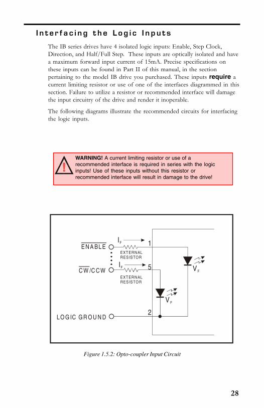
The IB series drives have 4 isolated logic inputs: Enable, Step Clock,Direction, and Half/Full Step. These inputs are optically isolated and havea maximum forward input current of 15mA. Precise specifications onthese inputs can be found in Part II of this manual, in the sectionpertaining to the model IB drive you purchased. These inputs require acurrent limiting resistor or use of one of the interfaces diagrammed in thissection. Failure to utilize a resistor or recommended interface will damagethe input circuitry of the drive and render it inoperable.
The following diagrams illustrate the recommended circuits for interfacingthe logic inputs.
WARNING! A current limiting resistor or use of arecommended interface is required in series with the logicinputs! Use of these inputs without this resistor orrecommended interface will result in damage to the drive!
Figure 1.5.2: Opto-coupler Input Circuit
E N A BLE
C W /C C W
LO G IC G R O U N D
IF
IF VF
V F
EXT ERN ALRES ISTOR
EXT ERN ALRES ISTOR
1
5
2
29
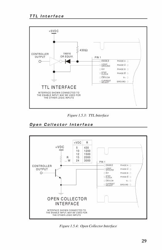
Figure 1.5.3: TTL Interface
O p e n C o l l e c t o r I n t e r f a c e
Figure 1.5.4: Open Collector Interface
E N A B L E
H
C W
LO G ICG R O U N D
/F
S T E PC LO C K
/C C W
C U R R E N TA D JU S T
P H A S E A
P H A S E
P H A S E B
P H A S E
V +
G R O U N D
A
B
PIN 1
DRAWNBY JA
+ 5 V D C
CONTROLLEROUTPUT
4 3 0Ω1N916
OR EQUIV.
T TL IN TE R FA C EIN TER FA C E SH O W N C O N N ECTED TO
THE E N ABLE IN PUT, M AY BE USED FO RTHE O THER LO G IC IN PUTS
T T L I n t e r f a c e
E N A B L E
H
C W
L O G ICG R O U N D
/F
S T E PC L O C K
/C C W
C U R R EN TA D JU S T
P H A S E A
P H A S E
P H A S E B
P H A S E
V +
G R O U N D
A
B
P IN 1
DRAWNBY JA
+V D C
CO NTR O LLE RO UTPUT
R… W
O P EN C O LLE C TO RIN TER FA C E
IN TE R FAC E SH O W N CO N N EC TE D TOTH E EN ABLE INP U T, M AY B E U SED FO R
TH E O THE R LO G IC INP UTS
+V DC
510121524
4301200150020003000
R

30
7 4 H C / 5 4 H C / 7 4 H C T / 5 4 H C T I n t e r f a c e
C on t r o l l i n g t h e Ou t p u t C u r r e n t
The IB series drivers are internally configured to run at full current. Inorder to lower the output current a resistor must be placed between pin 6(Current Adjust) and pin 7 (Power Ground). This resistor value will bedifferent for each model of the IB series. The section pertaining to eachparticular model contains a table that lists output current settings andadjust resistor values.
Figure 1.5.5: 74HC/54HC/74HCT/54HCT Interface
Figure 1.5.6: Current Adjust Resistor Placement
EN A BLE
H
C W
LO GICG R O UN D
/F
ST EPC LO C K
/C C W
C U R R EN TAD JU S T
PH A SE A
PH A SE
PH A SE
PH A SE B
V+
G R O UN D
A
B
PIN 1
DRAWNBY JA
+5VD C
C O N TR O LLE RO U T PUT
430… W
Ω
74H C /54H C /74H C T/54H C TIN TER FAC E
IN TER FAC E SHOW N CO N NECTED TOTHE EN ABLE INPU T, M AY BE USED FOR
THE O THER LOGIC INPUTS
EN A BLE
H
C W
LO GICG R O U N D
/F
ST EPC LO C K
/C C W
C U R RE N TAD JU S T
PH A SE A
PH A SE
PH A SE B
PH A SE
V+
G R O U N D
A
B
PIN 1
DRAWNBY JA
CURRE NT A DJUS TRES ISTO R
NOTE: See thesection in Part II ofthis documentpertaining to the
model IB drive purchased forresistor value tables.
NOTE: If a resistoris not placedbetween Pins 6and 7, the drive
will be at full current.

31
Figure 1.5.7: Switching Phase Currents
Figure 1.5.8: Isolated Switching of Phase Currents
It is possible to switch the current adjust resistor value using the circuitexamples provided in this section. These circuits may be used to switchfrom one output current setting to another, or to reduce the current in themotor windings when the motor is in a locked position. Use of this willreduce motor and drive heating considerably.
E N A B LE
H
C W
LO G ICG R O U N D
/F
S T E PC LO C K
/C C W
C U R R E N TA D JU S T
P H A S E A
P H A S E
P H A S E
P H A S E B
V +
G R O U N D
A
B
PIN 1
DRAWNBY JA
Q 1 Q 2
+5 V G S W ILL T U R N O N F E T SQ 1 - Q 2 : V N O 3 0 0 L O R E Q U IV.
R 1AD J R 2AD J
S e e H a rd w a re R e fe re n cep a rt fo r R (cu rre n ta d ju s t re s is to r) va lu es .
adj
EN A BL E
H
C W
L O GICG R O U N D
/F
ST EPC L O C K
/C C W
C U R R EN TAD JU S T
PH A SE A
PH A SE
PH A SE
PH A SE B
V+
G R O U N D
A
B
PIN 1
DRAWNBY JA
Q 1 (V N O 3 00 L O R E Q U IV.)
R A D J
R
+ 1 0V
4 N 2 5 /4 N 2 6
IF
1 0 0kΩ
+VR =
0 .2 x IF
M IN I = 10m AF
S e e H a rdw a re R e fere n cep a rt fo r R (cu rre n ta d ju s t re s is to r) va lu e s .
adj

32
S e c t i o n 1 . 6Tr o u b l e s h o o t i n g
S e c t i o n O v e r v i e w
This section will cover the following:
Basic Troubleshooting.
Common Problems/Solutions.
Contacting Application Support.
Product Return Procedure.
24 Month Limited Warranty.
B a s i c Tr o u b l e s h o o t i n g
In the event that your IB series drive doesn’t operate properly, the first stepis to identify whether the problem is electrical or mechanical in nature. Thenext step is to isolate the system component that is causing the problem.As part of this process you may have to disconnect the individual compo-nents that make up your system and verify that they operate independently.It is important to document each step in the troubleshooting process.You may need this documentation to refer back to at a later date. Thesedetails will greatly assist one of our application engineers in determiningthe problem should you need assistance.
Many of the problems that effect motion control systems can be traced toelectrical noise, software errors, or mistakes in wiring.
P r ob l em S ymp t oms a n d P o s s i b l e C a u s e s
S y m p t o m
Motor does not move.
P o s s i b l e P r o b l e m
No power.
Step clock is not grounded to opto supply ground.
Unit is in a reset condition.
Unit is disabled.

33
S y m p t o m
Motor moves in the wrong direction.
P o s s i b l e P r o b l e m
Motor phases may be connected in reverse.
S y m p t o m
Erratic motor motion.
P o s s i b l e P r o b l e m
Motor/power wiring unshielded or not twisted pair.
Logic wiring next to motor/power wiring.
Ground loop in system.
Open winding of motor.
Phase blown on drive.
S y m p t o m
Motor stalls during acceleration.
P o s s i b l e P r o b l e m
Incorrect current adjust setting or resistor value.
Motor is undersized for application.
Acceleration on controller is set to high.
Power supply voltage too low.
S y m p t o m
Excessive motor and driver heating.
P o s s i b l e P r o b l e m
Inadequate heat sinking / cooling.
Current set too high.

34
S y m p t o m
Inadequate holding torque.
P o s s i b l e P r o b l e m
Incorrect current adjust setting or resistor value.
Con t a c t i n g App l i c a t i o n S uppo r t
In the event that you are unable to isolate the problem with your IB seriesdriver, the first action you should take is to contact the distributor fromwhom you originally purchased your product or IMS Application Supportat 860-295-6102 or by fax at 860-295-6107. Be prepared to answer thefollowing questions:
What is the application?
In detail, how is the system configured?
What is the system environment? (Temperature, humidity,exposure to chemical vapors, etc.).
What external equipment is the system interfaced to?
Th e IMS Web S i t e
Another product support resource is the IMS website located atwww.imshome.com. This site is updated monthly with tech tips, applicationsand new product updates.
Re t u r n i n g Yo u r P r o d u c t t o IMS
If Application Support determines that your IB series drive needs to bereturned to the factory for repair or replacement, you will need to take thefollowing steps:
Obtain an RMA (Returned Material Authorization) numberand shipping instructions from Customer Service.
Fill out the “Reported Problem” field in detail on the RMAform that Customer Service will fax you.
Enclose the product being returned, and the RMA form inthe box. Package product in its original container ifpossible. If original packaging is unavailable ensure that theproduct is enclosed in approved antistatic packing material.Write the RMA number on the box.

35
The normal repair lead time is 10 business days. Should you need yourproduct returned in a shorter time period you may request that a “HOT”status be placed upon it while obtaining an RMA number. Should thefactory determine that the product repair is not covered under warranty,you will be notified of any charges.

36
Page Intentionally Left Blank
37
HardwareReference
Part II
Section 2.1–IB462
Section 2.2–IB463
Section 2.3–IB104
Section 2.4–IB106
Section 2.5–IB1010
38
S e c t i o n 2 . 1I B 4 6 2
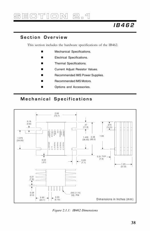
S e c t i o n O v e r v i e w
This section includes the hardware specifications of the IB462.
Mechanical Specifications.
Electrical Specifications.
Thermal Specifications.
Current Adjust Resistor Values.
Recommended IMS Power Supplies.
Recommended IMS Motors.
Options and Accessories.
M e c h a n i c a l S p e c i f i c a t i o n s
Figure 2.1.1: IB462 Dimensions
EN
AB
LE
HCW
LOG
ICG
RO
UN
D
/F
ST
EP
CLO
CK
/CC
W
CU
RR
EN
TA
DJU
ST
PH
AS
E A
PH
AS
E
PH
AS
E B
V+
GR
OU
ND A
PH
AS
E B
.5 7 5(1 4 .5 )
1 .9 5
0 .3 1 T Y P(7 .9 )
1 .2 5(3 1 .8 )
0 .3 1(7 .9 )
0 .0 9(2 .3 )
0 .9 5(2 4 .1 )
0 .2 0(5 .1 0 )
.0 4 5 (1 .14 ) S Q . P IN
2 .3 8(6 0 .5 )
1 .4 35(3 6 .4 5)
.4 7(11 .9)
0 .2 8(7 .1 )
2 .9 0(7 3 .7 )
1 .3 75(3 4 .9 3)
0 .1 9(4 .8 )
0 .0 2(.5 1 )
D im ensions in Inches (m m )

39
E l e c t r i c a l S p e c i f i c a t i o n s
Table 2.1.1: IB462 Electrical Specifications
Table 2.1.2: IB462 Thermal Specifications
T h e r m a l S p e c i f i c a t i o n s
snoitacificepSlacirtcelE264BI
noitacificepS noitidnoCtseT .niM .pyT .xaM tinU
TnoitidnoCtseTllarevO A CDV04=V+,C°52=
)egatloVrotoM(V+ 21 *04 V
Ii tnerruCtupnI 2 A
IQ tnerruCtnecseiuQ gnitaolFstuptuO 57 Am
V EC noitarutaSecruoS)h(tasegatloV
Ii A2= 8.1 6.2 V
V EC noitarutaSecruoS)i(tasegatloV
Ii A2= 7.1 4.2 V
B RV nwodkaerBesreveRtupnIegatloV
5 V
VF egatloVdrawroFtupnI IF Am01= 5.1 57.1 V
IF tnerruCdrawroFtupnI 5 5.7 51 Am
T KLC htdiWesluPkcolCpetS 3 Sm
TS emiTpu-teS F/H&WCC/WC 2 Sm
TH emiTdloH F/H&WCC/WC 5.5 Sm
FC ycneuqerFnoitatummoC 04 zHk
VsidelbasidstuptuoesahpehthtiwegatlovtupnimumixamehT* XAM .%01+
snoitacificepSlamrehT264BI
noitacificepS tinU
erutarepmeTtneibmA C°05+ot0
erutarepmeTegarotS C°521+ot04-
erutarepmeTesaCmumixaM C°07
NOTE: Additional cooling may be required to limit casetemperature to 70°C. An optional heat sink, IMS PN H-4X, isavailable. See Appendix B: Cooling Solutions, for details.

40
Cu r r e n t A d j u s t R e s i s t o r Va l u e s
The table below lists the phase currents and their associated adjust resistorvalue. Figure 2.1.2 illustrates the reference circuit and contains the equationfor calculating the current adjust resistor value.
Table 2.1.3: IB462 Current Adjust Resistor Values
264BIehtrofseulaVecnerefeRdnarotsiseRtsujdAtnerruC
tnerruCtuptuO)kaePspmA(
ecnerefeR)stloV(
eulaVrotsiseR)%1smhO(
1.0 50.0 0.12
2.0 01.0 2.44
3.0 51.0 8.96
4.0 02.0 001
5.0 52.0 331
6.0 03.0 961
7.0 53.0 512
8.0 04.0 762
9.0 54.0 423
0.1 05.0 204
1.1 55.0 784
2.1 06.0 406
3.1 56.0 057
4.1 07.0 139
5.1 57.0 0121
6.1 08.0 0261
7.1 58.0 0622
8.1 09.0 0753
9.1 59.0 0867
0.2 00.1 TIUCRICNEPO
NOTE: If a resistor is not placedbetween Pins 6 and 7, the drive willbe at full current.

41
Recommended IMS Powe r S upp l i e s
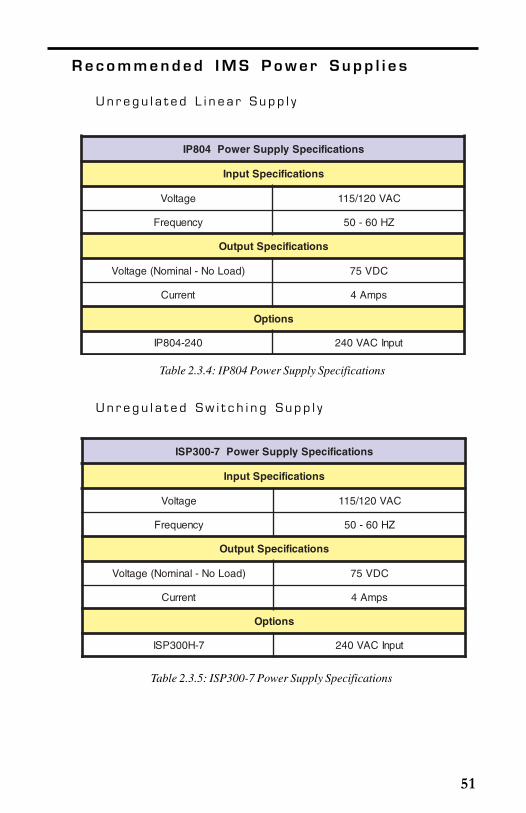
U n r e g u l a t e d L i n e a r S u p p l y
Recommended IMS Mo t o r s
IMS stocks the following 1.8° hybrid stepping motors that are recom-mended for the IB462. All IMS motors are CE marked. For moredetailed information on these motors, please see the IMS catalog or website at www.imshome.com.
17 Frame Motors
Single Shaft Double ShaftM2-1713-S .................................................................... M2-1713-DM2-1715-S .................................................................... M2-1715-DM2-1719-S .................................................................... M2-1719-D
23 Frame Motors
Single Shaft Double ShaftM2-2215-S .................................................................... M2-2215-DM2-2220-S .................................................................... M2-2220-DM2-2232-S .................................................................... M2-2232-D
snoitacificepSylppuSrewoP204PI
snoitacificepStupnI
egatloV CAV021/511
ycneuqerF ZH06-05
snoitacificepStuptuO
)daoLoN-lanimoN(egatloV CDV04
tnerruC spmA2
snoitpO
042-204PI tupnICAV042
Table 2.1.4: IP402 Power Supply Specifications

42
IMS also carries a new series of 23 frame enhanced stepping motors that arerecommended for use with the IB462. These motors use a unique relationshipbetween the rotor and stator to generate more torque per frame size whileensuring more precise positioning and increased accuracy.
The special design allows the motors to provide higher torque than standardstepping motors while maintaining a steadier torque and reducing torque drop-off.
The motors are available in 3 stack sizes, single or double shaft, with orwithout encoders. They handle currents up to 3 Amps in series or 6 Ampsparallel, and holding torque ranges from 95 oz-in to 230 oz-in (67 N-cm to162 N-cm).
These CE rated motors are ideal for applications where higher torque isrequired.
23 Frame High Torque Motors
Single Shaft Double ShaftMH-2218-S .................................................................. MH-2218-DMH-2222-S .................................................................. MH-2222-DMH-2231-S .................................................................. MH-2231-D
Op t i o n s a n d A c c e s s o r i e s
See appendices for descriptions and technical data on these accessories.
Thermal Isolating Pad ....................................................TI-462
Thermal Non-Isolating Pad ......................................... TN-462
Heat Sink ............................................................................H-4X
Interface Board ............................................................... OPT140
Plug-on Screw Terminal Set ............................................ TS-6
43
S e c t i o n 2 . 2I B 4 6 3
S e c t i o n O v e r v i e w
This section includes the hardware specifications of the IB463.
Mechanical Specifications.
Electrical Specifications.
Thermal Specifications.
Current Adjust Resistor Values.
Recommended IMS Power Supplies.
Recommended IMS Motors.
Options and Accessories.
M e c h a n i c a l S p e c i f i c a t i o n s
Figure 2.2.1: IB463 Dimensions
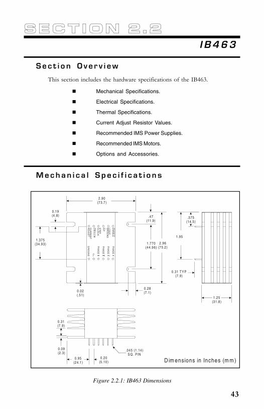
EN
AB
LE
HCW
LOG
ICG
RO
UN
D
/F
ST
EP
CLO
CK
/CC
W
CU
RR
EN
TA
DJU
ST
PH
AS
E A
PH
AS
E
PH
AS
E B
V+
GR
OU
ND A
PH
AS
E B
1 .375(3 4.9 3)
0 .19(4 .8)
2 .90(7 3.7 )
0 .02(.5 1)
1 .770(4 4.9 6)
0 .28(7 .1)
2 .96(7 5.2 )
.47(11.9)
.575(1 4.5 )
1 .95
0 .31 T Y P(7 .9)
1 .25(3 1.8 )
0 .31(7 .9)
0 .09(2 .3)
0 .95(2 4.1 )
0 .20(5 .10 )
.045 (1 .14 ) S Q . P IN
D im ensions in Inches (m m )
44
E l e c t r i c a l S p e c i f i c a t i o n s
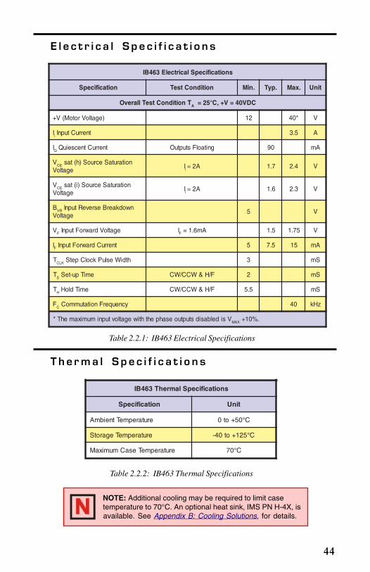
Table 2.2.1: IB463 Electrical Specifications
Table 2.2.2: IB463 Thermal Specifications
T h e r m a l S p e c i f i c a t i o n s
snoitacificepSlacirtcelE364BI
noitacificepS noitidnoCtseT .niM .pyT .xaM tinU
TnoitidnoCtseTllarevO A CDV04=V+,C°52=
)egatloVrotoM(V+ 21 *04 V
Ii tnerruCtupnI 5.3 A
IQ tnerruCtnecseiuQ gnitaolFstuptuO 09 Am
V EC noitarutaSecruoS)h(tasegatloV
Ii A2= 7.1 4.2 V
V EC noitarutaSecruoS)i(tasegatloV
Ii A2= 6.1 3.2 V
B RV nwodkaerBesreveRtupnIegatloV
5 V
VF egatloVdrawroFtupnI IF Am6.1= 5.1 57.1 V
IF tnerruCdrawroFtupnI 5 5.7 51 Am
T KLC htdiWesluPkcolCpetS 3 Sm
TS emiTpu-teS F/H&WCC/WC 2 Sm
TH emiTdloH F/H&WCC/WC 5.5 Sm
FC ycneuqerFnoitatummoC 04 zHk
VsidelbasidstuptuoesahpehthtiwegatlovtupnimumixamehT* XAM .%01+
snoitacificepSlamrehT364BI
noitacificepS tinU
erutarepmeTtneibmA C°05+ot0
erutarepmeTegarotS C°521+ot04-
erutarepmeTesaCmumixaM C°07
NOTE: Additional cooling may be required to limit casetemperature to 70°C. An optional heat sink, IMS PN H-4X, isavailable. See Appendix B: Cooling Solutions, for details.

45
Cu r r e n t A d j u s t R e s i s t o r Va l u e s
Table 2.2.3: IB463 Current Adjust Resistor Values
364BIehtrofseulaVecnerefeRdnarotsiseRtsujdAtnerruC
tnerruCtuptuO)kaePspmA(
ecnerefeR)stloV(
eulaVrotsiseR)%1smhO(
1.0 20..0 52.8
2.0 40.0 9.61
3.0 60.0 1.62
4.0 80.0 5.63
5.0 01.0 4.64
6.0 21.0 6.75
7.0 41.0 8.96
8.0 61.0 5.28
9.0 81.0 6.79
0.1 02.0 011
1.1 22.0 721
2.1 42.0 741
3.1 62.0 561
4.1 82.0 781
5.1 03.0 012
6.1 23.0 732
7.1 43.0 162
8.1 63.0 492
9.1 83.0 233
0.2 04.0 473
1.2 24.0 224
2.2 44.0 574
3.2 64.0 635
4.2 84.0 46
5.2 05.0 896
6.2 25.0 608
7.2 45.0 139
8.2 65.0 0011
9.2 85.0 0331
0.3 06.0 0561
1.3 26.0 0512
2.3 46.0 0492
3.3 66.0 0464
4.3 86.0 0359
5.3 07.0 TIUCRICNEPO

46
Recommended IMS Powe r S upp l i e s
U n r e g u l a t e d L i n e a r S u p p l y
Recommended IMS Mo t o r s
IMS stocks the following 1.8° hybrid stepping motors that are recom-mended for the IB463. All IMS motors are CE marked. For moredetailed information on these motors please see the IMS catalog or website at www.imshome.com.
17 Frame Motors
Single Shaft Double ShaftM2-1713-S .................................................................... M2-1713-DM2-1715-S .................................................................... M2-1715-DM2-1719-S .................................................................... M2-1719-D
23 Frame Motors
Single Shaft Double ShaftM2-2215-S .................................................................... M2-2215-DM2-2220-S .................................................................... M2-2220-DM2-2232-S .................................................................... M2-2232-DM2-2240-S .................................................................... M2-2240-D
IMS also carries a new series of 23 frame enhanced stepping motors thatare recommended for use with the IB463. These motors use a unique
snoitacificepSylppuSrewoP404PI
snoitacificepStupnI
egatloV CAV021/511
ycneuqerF ZH06-05
snoitacificepStuptuO
)daoLoN-lanimoN(egatloV CDV04
tnerruC spmA4
snoitpO
042-404PI tupnICAV042
Table 2.2.4: IP404 Power Supply Specifications

47
relationship between the rotor and stator to generate more torque perframe size while ensuring more precise positioning and increased accuracy.
The special design allows the motors to provide higher torque thanstandard stepping motors while maintaining a steadier torque andreducing torque drop-off.
The motors are available in 3 stack sizes, single or double shaft, with orwithout encoders. They handle currents up to 3 Amps in series or 6Amps parallel, and holding torque ranges from 95 oz-in to 230 oz-in (67N-cm to 162 N-cm).
These CE rated motors are ideal for applications where higher torque isrequired.
23 Frame High Torque Motors
Single Shaft Double ShaftMH-2218-S .................................................................. MH-2218-DMH-2222-S .................................................................. MH-2222-DMH-2231-S .................................................................. MH-2231-D
Op t i o n s a n d A c c e s s o r i e s
See appendices for descriptions and technical data on these accessories.
Thermal Isolating Pad ....................................................TI-463
Thermal Non-Isolating Pad ......................................... TN-463
Heat Sink ............................................................................H-4X
Interface Board ............................................................... OPT-140
Plug-on Screw Terminal Set ............................................. TS-6

48
S e c t i o n 2 . 3I B 1 0 4
S e c t i o n O v e r v i e w
This section includes the hardware specifications of the IB104.
Mechanical Specifications.
Electrical Specifications.
Thermal Specifications.
Current Adjust Resistor Values.
Recommended IMS Power Supplies.
Recommended IMS Motors.
Options and Accessories.
M e c h a n i c a l S p e c i f i c a t i o n s
Figure 2.3.1: IB104 Dimensions
ENAB LE
H
C W
LOGICG ROUN D
/F
STE PC LO C K
/CC W
C URREN TADJUST
PHAS E A
PHAS E
PHAS E
PHAS E B
V+
G ROUN D
A
B2.90
(73.7)
4.96(126.0)
1.00(25.4)
0.188(4.8)
0.28(7.1)
0.02(0.51)
0.10(2.54)
1.47(37.3)
0.27(6.86)
1.25(31.8)
0.31(7.9)
0.09(2.3)
0.95(24.1)
0.20(5.1)
.045 (1.14) S Q PIN
3.95(100.3)
0.95(24.1)
D im ensions in Inches (m m )
49
E l e c t r i c a l S p e c i f i c a t i o n s
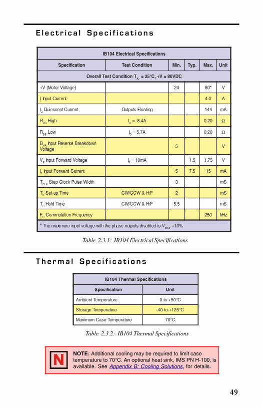
Table 2.3.1: IB104 Electrical Specifications
Table 2.3.2: IB104 Thermal Specifications
T h e r m a l S p e c i f i c a t i o n s
snoitacificepSlacirtcelE401BI
noitacificepS noitidnoCtseT .niM .pyT .xaM tinU
TnoitidnoCtseTllarevO A CDV08=V+,C°52=
)egatloVrotoM(V+ 42 *08 V
Ii tnerruCtupnI 0.4 A
IQ tnerruCtnecseiuQ gnitaolFstuptuO 441 Am
R SD hgiH ID A4.8-= 02.0 Ω
R SD woL ID A7.5= 02.0 Ω
B RV nwodkaerBesreveRtupnIegatloV
5 V
VF egatloVdrawroFtupnI IF Am01= 5.1 57.1 V
IF tnerruCdrawroFtupnI 5 5.7 51 Am
T KLC htdiWesluPkcolCpetS 3 Sm
TS emiTpu-teS F/H&WCC/WC 2 Sm
TH emiTdloH F/H&WCC/WC 5.5 Sm
FC ycneuqerFnoitatummoC 052 zHk
VsidelbasidstuptuoesahpehthtiwegatlovtupnimumixamehT* XAM .%01+
snoitacificepSlamrehT401BI
noitacificepS tinU
erutarepmeTtneibmA C°05+ot0
erutarepmeTegarotS C°521+ot04-
erutarepmeTesaCmumixaM C°07
NOTE: Additional cooling may be required to limit casetemperature to 70°C. An optional heat sink, IMS PN H-100, isavailable. See Appendix B: Cooling Solutions, for details.
50
Cu r r e n t A d j u s t R e s i s t o r Va l u e s
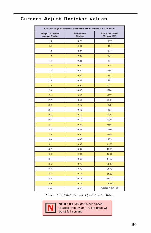
Table 2.3.3: IB104 Current Adjust Resistor Values
401BIehtrofseulaVecnerefeRdnarotsiseRtsujdAtnerruC
tnerruCtuptuO)kaePspmA(
ecnerefeR)stloV(
eulaVrotsiseR)%1smhO(
0.1 02.0 701
1.1 22.0 121
2.1 42.0 731
3.1 62.0 451
4.1 82.0 471
5.1 03.0 191
6.1 23.0 512
7.1 43.0 732
8.1 63.0 162
9.1 83.0 782
0.2 04.0 423
1.2 24.0 753
2.2 44.0 293
3.2 64.0 234
4.2 84.0 784
5.2 05.0 635
6.2 25.0 095
7.2 45.0 566
8.2 65.0 057
9.2 85.0 548
0.3 06.0 359
1.3 26.0 0011
2.3 46.0 0721
3.3 66.0 0051
4.3 86.0 0871
5.3 07.0 0122
6.3 27.0 0782
7.3 47.0 0293
8.3 67.0 0095
9.3 87.0 00421
0.4 08.0 TIUCRICNEPO
NOTE: If a resistor is not placedbetween Pins 6 and 7, the drive willbe at full current.
51
Recommended IMS Powe r S upp l i e s
U n r e g u l a t e d L i n e a r S u p p l y
U n r e g u l a t e d S w i t c h i n g S u p p l y
snoitacificepSylppuSrewoP408PI
snoitacificepStupnI
egatloV CAV021/511
ycneuqerF ZH06-05
snoitacificepStuptuO
)daoLoN-lanimoN(egatloV CDV57
tnerruC spmA4
snoitpO
042-408PI tupnICAV042
Table 2.3.4: IP804 Power Supply Specifications
snoitacificepSylppuSrewoP7-003PSI
snoitacificepStupnI
egatloV CAV021/511
ycneuqerF ZH06-05
snoitacificepStuptuO
)daoLoN-lanimoN(egatloV CDV57
tnerruC spmA4
snoitpO
7-H003PSI tupnICAV042
Table 2.3.5: ISP300-7 Power Supply Specifications

52
Recommended IMS Mo t o r s
IMS stocks the following 1.8° hybrid stepping motors that are recom-mended for the IB104. All IMS motors are CE marked. For more detailedinformation on these motors please see the IMS catalog or web site atwww.imshome.com.
23 Frame MotorsSingle Shaft Double ShaftM2-2215-S .................................................................... M2-2215-DM2-2220-S .................................................................... M2-2220-DM2-2232-S .................................................................... M2-2232-DM2-2240-S .................................................................... M2-2240-D
34 Frame MotorsSingle Shaft Double ShaftM2-3424-S .................................................................... M2-3424-DM2-3437-S .................................................................... M2-3437-D
IMS also carries a new series of 23 frame enhanced stepping motors that arerecommended for use with the IB104. These motors use a unique relationshipbetween the rotor and stator to generate more torque per frame size while ensuringmore precise positioning and increased accuracy.
The special design allows the motors to provide higher torque than standardstepping motors while maintaining a steadier torque and reducing torque drop-off.
The motors are available in 3 stack sizes, single or double shaft, with or withoutencoders. They handle currents up to 3 Amps in series or 6 Amps parallel, andholding torque ranges from 95 oz-in to 230 oz-in (67 N-cm to 162 N-cm).
These CE rated motors are ideal for applications where higher torque is required.
23 Frame High Torque MotorsSingle Shaft Double ShaftMH-2218-S .................................................................. MH-2218-DMH-2222-S .................................................................. MH-2222-DMH-2231-S .................................................................. MH-2231-D
Op t i o n s a n d A c c e s s o r i e s
See appendices for descriptions and technical data on these accessories.
Thermal Isolating Pad ....................................................TI-100Thermal Non-Isolating Pad ......................................... TN-100Heat Sink ........................................................................... H-100Interface Board ............................................................... OPT-140Plug-on Screw Terminal Set ............................................. TS-6

53
S e c t i o n 2 . 4I B 1 0 6
S e c t i o n O v e r v i e w
This section includes the hardware specifications of the IB106.
Mechanical Specifications.
Electrical Specifications.
Thermal Specifications.
Current Adjust Resistor Values.
Recommended IMS Power Supplies.
Recommended IMS Motors.
Options and Accessories.
M e c h a n i c a l S p e c i f i c a t i o n s
Figure 2.4.1: IB106 Dimensions
ENABLE
H
CW
LOGICGROUND
/F
STEPCLOCK
/CCW
CURRENTADJUST
PHASE A
PHASE
PHASE
PHASE B
V+
GROUND
A
B2.90
(73.7)
4.96(126.0)
1.00(25.4)
0.188(4.8)
0.28(7.1)
0.02(0.51)
0.10(2.54)
1.47(37.3)
0.27(6.86)
1.25(31.8)
0.31(7.9)
0.09(2.3)
0.95(24.1)
0.20(5.1)
.045 (1.14) SQ PIN
3.95(100.3)
0.95(24.1)
D im ensions in Inches (m m )

54
E l e c t r i c a l S p e c i f i c a t i o n s
Table 2.4.1: IB106 Electrical Specifications
Table 2.4.2: IB106 Thermal Specifications
T h e r m a l S p e c i f i c a t i o n s
snoitacificepSlacirtcelE601BI
noitacificepS noitidnoCtseT .niM .pyT .xaM tinU
TnoitidnoCtseTllarevO A CDV08=V+,C°52=
)egatloVrotoM(V+ 42 *08 V
Ii tnerruCtupnI 0.6 A
IQ tnerruCtnecseiuQ gnitaolFstuptuO 441 Am
R )NO(SD HGIH ID A11-= 711.0 Ω
R )NO(SD WOL ID A51= 50.0 77.0 Ω
B RV nwodkaerBesreveRtupnIegatloV
5 V
VF egatloVdrawroFtupnI IF Am6.1= 5.1 57.1 V
IF tnerruCdrawroFtupnI 5 3.6 51 Am
T KLC htdiWesluPkcolCpetS 3 Sm
TS emiTpu-teS F/H&WCC/WC 2 Sm
TH emiTdloH F/H&WCC/WC 5.5 Sm
FC ycneuqerFnoitatummoC 052 zHk
VsidelbasidstuptuoesahpehthtiwegatlovtupnimumixamehT* XAM .%01+
snoitacificepSlamrehT601BI
noitacificepS tinU
erutarepmeTtneibmA C°05+ot0
erutarepmeTegarotS C°521+ot04-
erutarepmeTesaCmumixaM C°07
NOTE: Additional cooling may be required to limit casetemperature to 70°C. An optional heat sink, IMS PN H-100 isavailable. See Appendix B: Cooling Solutions, for details.
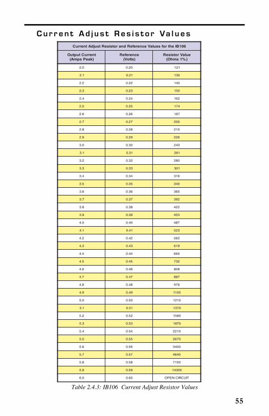
55
Cu r r e n t A d j u s t R e s i s t o r Va l u e s
Table 2.4.3: IB106 Current Adjust Resistor Values
601BIehtrofseulaVecnerefeRdnarotsiseRtsujdAtnerruC
tnerruCtuptuO)kaePspmA(
ecnerefeR)stloV(
eulaVrotsiseR)%1smhO(
0.2 02.0 121
1.2 12.0 031
2.2 22.0 041
3.2 32.0 051
4.2 42.0 261
5.2 52.0 471
6.2 62.0 781
7.2 72.0 002
8.2 82.0 512
9.2 92.0 622
0.3 03.0 342
1.3 13.0 162
2.3 23.0 082
3.3 33.0 103
4.3 43.0 613
5.3 53.0 043
6.3 63.0 563
7.3 73.0 293
8.3 83.0 224
9.3 93.0 354
0.4 04.0 784
1.4 14.0 325
2.4 24.0 265
3.4 34.0 916
4.4 44.0 566
5.4 54.0 237
6.4 64.0 608
7.4 74.0 788
8.4 84.0 679
9.4 94.0 0011
0.5 05.0 0121
1.5 15.0 0731
2.5 25.0 0851
3.5 35.0 0781
4.5 45.0 0122
5.5 55.0 0762
6.5 65.0 0043
7.5 75.0 0464
8.5 85.0 0517
9.5 95.0 00341
0.6 06.0 TIUCRICNEPO

56
Recommended IMS Powe r S upp l i e s
U n r e g u l a t e d L i n e a r S u p p l y
U n r e g u l a t e d S w i t c h i n g S u p p l y
snoitacificepSylppuSrewoP408PI
snoitacificepStupnI
egatloV CAV021/511
ycneuqerF ZH06-05
snoitacificepStuptuO
)daoLoN-lanimoN(egatloV CDV57
tnerruC spmA4
snoitpO
042-408PI tupnICAV042
Table 2.4.4: IP804 Power Supply Specifications
snoitacificepSylppuSrewoP7-003PSI
snoitacificepStupnI
egatloV CAV021/511
ycneuqerF ZH06-05
snoitacificepStuptuO
)daoLoN-lanimoN(egatloV CDV57
tnerruC spmA4
snoitpO
7-H003PSI tupnICAV042
Table 2.4.5: ISP300-7 Power Supply Specifications

57
Recommended IMS Mo t o r s
IMS stocks the following 1.8° hybrid stepping motors that are recom-mended for the IB106. All IMS motors are CE marked. For more detailedinformation on these motors please see the IMS catalog or web site atwww.imshome.com.
23 Frame Motors
Single Shaft Double ShaftM2-2215-S .................................................................... M2-2215-DM2-2220-S .................................................................... M2-2220-DM2-2232-S .................................................................... M2-2232-DM2-2240-S .................................................................... M2-2240-D
34 Frame Motors
Single Shaft Double ShaftM2-3424-S .................................................................... M2-3424-DM2-3437-S .................................................................... M2-3437-DM2-3450-S .................................................................... M2-3450-D
IMS also carries a new series of 23 frame enhanced stepping motors that arerecommended for use with the IB106. These motors use a unique relationshipbetween the rotor and stator to generate more torque per frame size whileensuring more precise positioning and increased accuracy.
The special design allows the motors to provide higher torque than standardstepping motors while maintaining a steadier torque and reducing torque drop-off.
The motors are available in 3 stack sizes, single or double shaft, with or withoutencoders. They handle currents up to 3 Amps in series or 6 Amps parallel, andholding torque ranges from 95 oz-in to 230 oz-in (67 N-cm to 162 N-cm).
These CE rated motors are ideal for applications where higher torque is required.
23 Frame High Torque Motors
Single Shaft Double ShaftMH-2218-S .................................................................. MH-2218-DMH-2222-S .................................................................. MH-2222-DMH-2231-S .................................................................. MH-2231-D
Op t i o n s a n d A c c e s s o r i e s
Thermal Isolating Pad ....................................................TI-100Thermal Non-Isolating Pad ......................................... TN-100Heat Sink ........................................................................... H-100Interface Board ............................................................... OPT-140Plug-on Screw Terminal Set ............................................. TS-6

58
S e c t i o n 2 . 5I B 1 0 1 0
S e c t i o n O v e r v i e w
This section includes the hardware specifications of the IB1010.
Mechanical Specifications.
Electrical Specifications.
Thermal Specifications.
Current Adjust Resistor Values.
Recommended IMS Power Supplies.
Recommended IMS Motors.
Options and Accessories.
M e c h a n i c a l S p e c i f i c a t i o n s
Figure 2.5.1: IB1010 Dimensions
ENABLE
H
CW
LOGICGROUND
/F
STEPCLOCK
/CCW
CURRENTADJUST
PHASE A
PHASE
PHASE
PHASE B
V+
GROUND
A
B2.90
(73.7)
4.96(126.0)
1.00(25.4)
0.188(4.8)
0.28(7.1)
0.02(0.51)
0.10(2.54)
1.47(37.3)
0.27(6.86)
1.25(31.8)
0.31(7.9)
0.09(2.3)
0.95(24.1)
0.20(5.1)
.045 (1.14) SQ PIN
3.95(100.3)
0.95(24.1)
D im ensions in Inches (m m )
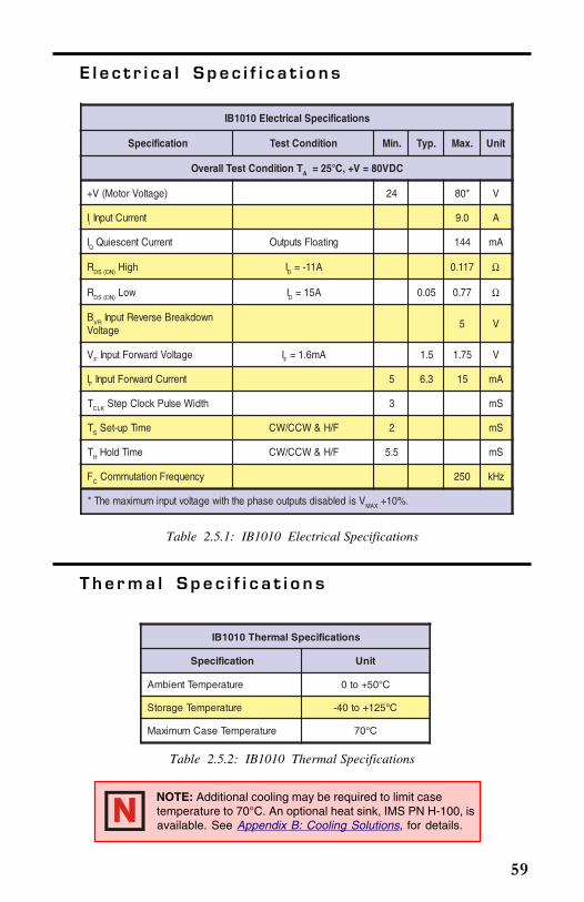
59
E l e c t r i c a l S p e c i f i c a t i o n s
Table 2.5.1: IB1010 Electrical Specifications
Table 2.5.2: IB1010 Thermal Specifications
NOTE: Additional cooling may be required to limit casetemperature to 70°C. An optional heat sink, IMS PN H-100, isavailable. See Appendix B: Cooling Solutions, for details.
T h e r m a l S p e c i f i c a t i o n s
snoitacificepSlacirtcelE0101BI
noitacificepS noitidnoCtseT .niM .pyT .xaM tinU
TnoitidnoCtseTllarevO A CDV08=V+,C°52=
)egatloVrotoM(V+ 42 *08 V
Ii tnerruCtupnI 0.9 A
IQ tnerruCtnecseiuQ gnitaolFstuptuO 441 Am
R )NO(SD hgiH ID A11-= 711.0 Ω
R )NO(SD woL ID A51= 50.0 77.0 Ω
B RV nwodkaerBesreveRtupnIegatloV
5 V
VF egatloVdrawroFtupnI IF Am6.1= 5.1 57.1 V
IF tnerruCdrawroFtupnI 5 3.6 51 Am
T KLC htdiWesluPkcolCpetS 3 Sm
TS emiTpu-teS F/H&WCC/WC 2 Sm
TH emiTdloH F/H&WCC/WC 5.5 Sm
FC ycneuqerFnoitatummoC 052 zHk
VsidelbasidstuptuoesahpehthtiwegatlovtupnimumixamehT* XAM .%01+
snoitacificepSlamrehT0101BI
noitacificepS tinU
erutarepmeTtneibmA C°05+ot0
erutarepmeTegarotS C°521+ot04-
erutarepmeTesaCmumixaM C°07

60
Cu r r e n t A d j u s t R e s i s t o r Va l u e s
Table 2.5.3: IB1010 Current Adjust Resistor Values
0101BIehtrofseulaVecnerefeRdnarotsiseRtsujdAtnerruC
tnerruCtuptuO)kaePspmA(
ecnerefeR)stloV(
eulaVrotsiseR)%1smhO(
0.2 02.0 201
2.2 22.0 511
4.2 42.0 031
6.2 62.0 741
8.2 82.0 261
0.3 03.0 871
2.3 23.0 691
4.3 43.0 122
6.3 63.0 732
8.3 83.0 162
0.4 04.0 782
2.4 24.0 613
4.4 44.0 423
6.4 64.0 473
8.4 84.0 214
0.5 05.0 354
2.5 25.0 784
4.5 45.0 635
6.5 65.0 095
8.5 85.0 946
0.6 06.0 517
2.6 26.0 787
4.6 46.0 788
6.6 66.0 679
8.6 86.0 0011
0.7 07.0 0721
2.7 27.0 0741
4.7 47.0 0561
6.7 67.0 0691
8.7 87.0 0232
0.8 08.0 0782
2.8 28.0 0563
4.8 48.0 0994
6.8 68.0 0867
8.8 88.0 00851
0.9 09.0 TIUCRICNEPO

61
Recommended IMS Powe r S upp l i e s
U n r e g u l a t e d L i n e a r S u p p l y
Recommended IMS Mo t o r s
IMS stocks the following 1.8° hybrid stepping motors that are recom-mended for the IB1010 All IMS motors are CE marked. For moredetailed information on these motors please see the IMS catalog or website at www.imshome.com.
34 Frame Motors
Single Shaft Double ShaftM2-3450-S .................................................................... M2-3450-D
42 Frame Motors
Single Shaft Double ShaftM2-4247-S .................................................................... M2-4247-DM2-4270-S .................................................................... M2-4270-DM2-4288-S .................................................................... M2-4288-D
snoitacificepSylppuSrewoP608PI
snoitacificepStupnI
egatloV CAV021/511
ycneuqerF ZH06-05
snoitacificepStuptuO
)daoLoN-lanimoN(egatloV CDV57
tnerruC spmA6
snoitpO
042-608PI tupnICAV042
Table 2.5.4: IP806 Power Supply Specifications

62
Op t i o n s a n d A c c e s s o r i e s
See appendices for descriptions and technical data on these accessories.
Thermal Isolating Pad ....................................................TI-100
Thermal Non-Isolating Pad ......................................... TN-100
Heat Sink ........................................................................... H-100
Interface Board ............................................................... OPT-140
Plug-on Screw Terminal Set ............................................. TS-6

63
A p p e n d i x AO P T 1 4 0
Op t i o n a l I n t e r f a c e B oa r d
The OPT140 adds such features to the IB seriesdrive as:
A Removable Screw Terminal Interface.
Isolated Current Reduction.
470Ω Pull-up Resistors on Logic Inputs.
Input Capacitor.
D e t e r m i n i n g t h e R e s i s t o r V a l u e s
S e t t i n g t h e O u t p u t C u r r e n t
To set the output current on the IB series drive using the OPT140 boardyou will need to place R4 (See Figure A.1 below for resistor location). Thevalue resistor needed will match the resistor table for the model IB driveyou purchased.
Figure A.1: OPT-140 Dimensions
D C
4N25
4315TK
19
R 5
R 1
R 4IMS O P T140
Q 1
P1
1 2 3 4 5 6 7 8 9 10 11 12 13 14
2.26(57.5)
3.00(76.2)
1.28(32.5)
Current Adjust
ReductionAdjust
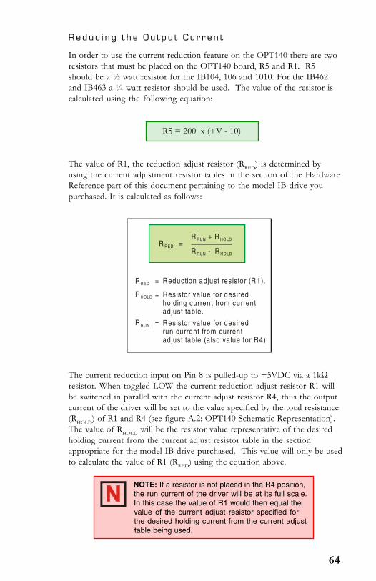
64
R e d u c i n g t h e O u t p u t C u r r e n t
In order to use the current reduction feature on the OPT140 there are tworesistors that must be placed on the OPT140 board, R5 and R1. R5should be a ½ watt resistor for the IB104, 106 and 1010. For the IB462and IB463 a ¼ watt resistor should be used. The value of the resistor iscalculated using the following equation:
R5 = 200 x (+V - 10)
The value of R1, the reduction adjust resistor (RRED) is determined byusing the current adjustment resistor tables in the section of the HardwareReference part of this document pertaining to the model IB drive youpurchased. It is calculated as follows:
The current reduction input on Pin 8 is pulled-up to +5VDC via a 1kΩresistor. When toggled LOW the current reduction adjust resistor R1 willbe switched in parallel with the current adjust resistor R4, thus the outputcurrent of the driver will be set to the value specified by the total resistance(RHOLD) of R1 and R4 (see figure A.2: OPT140 Schematic Representation).The value of RHOLD will be the resistor value representative of the desiredholding current from the current adjust resistor table in the sectionappropriate for the model IB drive purchased. This value will only be usedto calculate the value of R1 (RRED) using the equation above.
R + RRUN HO LD
R - RRUN HOLD
R RED =
R RED
R HOLD
R RUN
=
=
=
Reduction adjust res isto r (R 1).
Resistor va lue fo r desiredhold ing curren t from currentadjust table .
Resistor va lue fo r desiredrun current from currentadjust table (a lso value for R4).
NOTE: If a resistor is not placed in the R4 position,the run current of the driver will be at its full scale.In this case the value of R1 would then equal thevalue of the current adjust resistor specified forthe desired holding current from the current adjusttable being used.
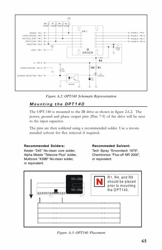
65
Figure A.3: OPT140 Placement
M o u n t i n g t h e O P T 1 4 0
The OPT-140 is mounted to the IB drive as shown in figure 2.6.2. Thepower, ground and phase output pins (Pins 7-9) of the drive will be nextto the input capacitor.
The pins are then soldered using a recommended solder. Use a recom-mended solvent for flux removal if required.
Recommended Solders: Recommeded Solvent:Kester “245” No-clean core solder, Tech Spray “Envorotech 1679”,Alpha Metals “Telecore Plus” solder, Chemtronics “Flux-off NR 2000”,Multicore “X39B” No-clean solder, or equivalent.or equivalent.
Figure A.2: OPT140 Schematic Representation
IBD R IV E R
PIN 1
+5V
+5V
+5V
R8470Ω
R7470Ω
R6470Ω
R2470Ω
R 31kΩ
C 12200 F
100Vµ
R5 R1
R4
Z 110V
Q 1V N O 300L
4N 25 /26
+
P H A S E A P IN 9
P H A S E A P IN 1 0
P H A S E B P IN 11
P H A S E B P IN 1 2
E N A B L E P IN 1
L O G IC G R O U N D P IN 2
H A L F /FU L L S TE P P IN 4
S T E P C L O C K P IN 5
D IR E C T IO N P IN 6
+ 5V D C P IN 7
P O W E R G R O U N D P IN 14
+ V P IN 13
C U R R E N T R E D U C TIO N P IN 8
R 1, R 4 , and R 5shou ld be p lacedprior to m ounting the O P T140.

66
Table A.1: OPT140 Pin Configuration
O P T 1 4 0 P i n C o n f i g u r a t i o n
WARNING! Do not connect +5VDC directly to pins 1, 4, 5, 6. Anopen collector driver should be used to control these inputs. SeeSection 1.5: Interfacing to the IB Series Drive, for interfaceconfigurations!
noitpircseDdnatnemngissAniP041-TPO
#NIP NOITCNUF SLIATED
1 elbanEstuptuoesahpeht,etats)evitca(WOLcigoLaninehW
.delbaneera
2 dnuorGcigoLehtrofhtapnruterehtsinipsihT.nommoClangiScigoL
dluohsnipsihtnoitalosiniatniamotredronI.stupnicigol.)dnuorGrewoP(7nipotdetcennocebton
3 tcennoCoN -
4 tupnIpetSlluF/flaHeeS.tupnitcelespetSlluF/flaH :2noitceS,1traP
noitarepOfoyroehT .sliatederomrof
5 tupnIkcolCpetStupnisihtnoeslupHGIHevitcanA.tupnikcolCpetS
nosruccopetsehT.tnemercnienorotomehtsecnavda.langissihtfoegdegnillafeht
6 tupnIWCC/WC
.tupnilortnocnoitceridesiwkcolcretnuoc/esiwkcolCehtnosdnepednoitatorrotomfonoitceridlacisyhP
yllanretnisitupnisihT.sgnidniwrotomehtfonoitcennoc.revirdehtnidezinorhcnys
7 CDV5+ .tupniCDV5+
8 noitcudeRtnerruCehtnitnerrucehtecuderlliwtupnisihtnoWOLcigoL
eeS.4Rdna1RybdeificepseulavehtotsgnidniwrotomnerruCtuptuOehtgnicudeR t .noitaluclacrotsiserrof,
9 BØ .tuptuoBesahprotoM
01 BØ .tuptuoBesahprotoM
11 AØ .tuptuoAesahprotoM
21 AØ .tuptuoAesahprotoM
31 V+ .decafretnigniebevirdseiresBIrofnoitacificepseeS
41 DNG .dnuorgrewoP

67
A p p e n d i x BC o o l i n g S o l u t i o n s
H -4X Hea t S i n k
The H-4X heat sink is designed for use withthe IB462 and IB463. The H-4X comes withthe following items:
(1) H-4X heat sink.
(4) 8 X 32 mounting screws/washers.(1) TN-462 or TN-463 non-isolating thermal pad.
M e c h a n i c a l S p e c i f i c a t i o n s
6.00(152.4)
5.50(139.7)
3.15(80.1)
3.51(89.5)
8 X32 Threaded6 PLACES
IB462
IB463
0.85(21.6)
Figure B.1: H-4X Heat Sink, Dimensions in Inches (mm)
H -100 Hea t S i n k
The H-100 heat sink is designed for use with the IB104, IB106 andIB1010. The H-100 comes with the following items:
(1) H-100 heat sink.
(4) 8 X 32 mounting screws/washers.
(1) TN-100 non-isolating thermal pad.
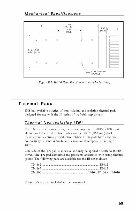
68
M e c h a n i c a l S p e c i f i c a t i o n s
7.00(177.8)
2.93(74.4)
2.48(63.0)
4.15(105.4)
8 X32 Threaded4 PLACES
1.32(33.5)
Figure B.2: H-100 Heat Sink, Dimensions in Inches (mm)
Th e rma l P a d s
IMS has available a series of non-isolating and isolating thermal padsdesigned for use with the IB series of half/full step drivers.
T h e r m a l N o n - I s o l a t i n g ( T N )
The TN thermal non-isolating pad is a composite of .0015” (.038 mm)aluminum foil coated on both sides with a .0025” (.063 mm) thickthermally and electrically conductive rubber. These pads have a thermalconductivity of 0.65 W/m-K and a maximum temperature rating of180°C.
One side of the TN pad is adhesive and may be applied directly to the IBdriver. The TN pad eliminates the problems associated with using thermalgrease. The following pads are available for the IB series drives:
TN-462 ............................................................................... IB462TN-463 ............................................................................... IB463TN-100 ............................................................... IB104, IB106 & IB1010
These pads are also included in the heat sink kit.

69
T h e r m a l I s o l a t i n g ( T I )
The TI thermal isolating pad uses a 0.006” (0.15mm) special film whichhas high thermal conductivity (0.9 W/m-K) and high dielectric strength(5000 Cps). The TI thermal insulating pad can withstand high voltagesand does not require thermal grease to transfer heat. The following padsare available for the IB series drivers:
TI-462 ................................................................................. IB462TI-463 ................................................................................. IB463TI-100 ................................................................. IB104, IB106 & IB1010

70
A P P e n d i x CM i s c e l l a n e o u s A c c e s s o r i e s
TS - 6 S c r ew Te r m i n a l S e t
The TS-6 screw terminal set is available asan option for the IB series drivers. Thesesix position terminal blocks plug directlyonto the IB drive connector pins.
There are two of the six positionterminals per set.
When using the TS-6 screw terminals thefollowing practices should be observed:
Wire Size .................................................................... 14 to 22 AWGWire Strip Length .................................................... 0.238” (6.0 mm)Tightening Torque ................................................ 7 lb-in (0.79 N-m)

TWENTY- FOUR MONTH L IM I T EDW A R R A N T Y
Intelligent Motion Systems, Inc., warrants its products against defects inmaterials and workmanship for a period of 24 months from receipt by theend-user. During the warranty period, IMS will either, at its option, repair orreplace Products which prove to be defective.
EXCLUSIONS
The above warranty shall not apply to defects resulting from: improper orinadequate handling by customer; improper or inadequate customer wiring;unauthorized modification or misuse; or operation outside of the electricaland/or environmental specifications for the Product.
OBTAINING WARRANTY SERVICE
To obtain warranty service, a returned material authorization number (RMA)must be obtained from customer service at (860) 295-6102 before returningproduct for service. Customer shall prepay shipping charges for Productsreturned to IMS for warranty service and IMS shall pay for return ofProducts to customer. However, customer shall pay all shipping charges,duties and taxes for Products returned to IMS from another country.
WARRANTY LIMITATIONS
IMS makes no other warranty, either expressed or implied, with respect tothe Product. IMS specifically disclaims the implied warranties of merchant-ability and fitness for a particular purpose. Some jurisdictions do not allowlimitations on how long an implied warranty lasts, so the above limitation orexclusion may not apply to you. However, any implied warranty of merchant-ability or fitness is limited to the 24-month duration of this written warranty.
EXCLUSIVE REMEDIES
If your Product should fail during the warranty period, call customer serviceat (860) 295-6102 to obtain a returned material authorization number (RMA)before returning product for service. Please include a written description ofthe problem along with contact name and address. Send failed product to:Intelligent Motion Systems, Inc., 370 N. Main St., Marlborough, Connecticut06447. Also enclose information regarding the circumstances prior toProduct failure.

IB Series Operating InstructionsOM-IB SERIESV05.19.2000