ibacos 2001 final technical report: building-scale project ... · march 2003 • nrel/sr-550-31506...
TRANSCRIPT

March 2003 • NREL/SR-550-31506
IBACOS Consortium Pittsburgh, Pennsylvania
IBACOS 2001 Final Technical Report: Building-Scale Project Results
National Renewable Energy Laboratory 1617 Cole Boulevard Golden, Colorado 80401-3393 NREL is a U.S. Department of Energy Laboratory Operated by Midwest Research Institute • Battelle • Bechtel
Contract No. DE-AC36-99-GO10337

March 2003 • NREL/SR-550-31506
IBACOS 2001 Final Technical Report: Building-Scale Project Results
IBACOS Consortium Pittsburgh, Pennsylvania
NREL Technical Monitor: P. Norton Prepared under Subcontract No. Task Order KAR-8-18608-12
National Renewable Energy Laboratory 1617 Cole Boulevard Golden, Colorado 80401-3393 NREL is a U.S. Department of Energy Laboratory Operated by Midwest Research Institute • Battelle • Bechtel
Contract No. DE-AC36-99-GO10337

NOTICE This report was prepared as an account of work sponsored by an agency of the United States government. Neither the United States government nor any agency thereof, nor any of their employees, makes any warranty, express or implied, or assumes any legal liability or responsibility for the accuracy, completeness, or usefulness of any information, apparatus, product, or process disclosed, or represents that its use would not infringe privately owned rights. Reference herein to any specific commercial product, process, or service by trade name, trademark, manufacturer, or otherwise does not necessarily constitute or imply its endorsement, recommendation, or favoring by the United States government or any agency thereof. The views and opinions of authors expressed herein do not necessarily state or reflect those of the United States government or any agency thereof.
Available electronically at http://www.osti.gov/bridge
Available for a processing fee to U.S. Department of Energy and its contractors, in paper, from:
U.S. Department of Energy Office of Scientific and Technical Information P.O. Box 62 Oak Ridge, TN 37831-0062 phone: 865.576.8401 fax: 865.576.5728 email: [email protected]
Available for sale to the public, in paper, from:
U.S. Department of Commerce National Technical Information Service 5285 Port Royal Road Springfield, VA 22161 phone: 800.553.6847 fax: 703.605.6900 email: [email protected] online ordering: http://www.ntis.gov/ordering.htm
Printed on paper containing at least 50% wastepaper, including 20% postconsumer waste

i
Table of Contents
Building-Scale Project Results ..............................................................................1
John Wieland Homes and Neighborhoods: Atlanta, Georgia ................................2
Greystone Village: Cicero, Indiana......................................................................12
Medallion Homes: San Antonio, Texas ...............................................................19
Farm Development: Dutchess County, New York ...............................................27
ContraVest Properties: Tucson, Arizona .............................................................38
Montgomery and Rust, Village A Pilot Home in Summerset at Frick Park: Pittsburgh, Pennsylvania ...............................................................................49
Bibliography ........................................................................................................60

ii

iii
List of Figures
Figure 1. Front elevation of The New American Home 2002 ................................................2
Figure 2. The home has five zone dampers; two can be seen on supply ductwork coming from one of the two air handlers .................................................................4
Figure 3. Analyzing the fan and furnace control system was a key part of evaluating the performance of the home. The control settings inside each unit were evaluated to ensure that air distribution performance would meet design goals ......................4
Figure 4. The child’s loft is located in attic space behind the vaulted roof rafters. The OSB sheathing was installed on its outward-facing walls to separate the loft space from the attic, thereby improving building airtightness and thermal performance ..............................................................................................7
Figure 5. Building felt was used to provide greater wall moisture protection behind the cultured stone. Membrane flashing was used to cover the sill rough opening. The top window flange was slipped under the housewrap after the window was installed with its flanges back caulked (except for the sill flange) ........9
Figure 6. The ranch and two-story model pilot homes .........................................................12
Figure 7. The builder constructed an unvented crawlspace with insulated walls and a source for conditioned air............................................................................14
Figure 8. Front elevation of the pilot home with synthetic stone cladding .............................19
Figure 9. The final duct installation incorporated a horizontal duct board trunk in the bulkhead with flex duct runs perpendicular to this main trunk ...............................23
Figure 10. A fresh-air intake duct with a constant airflow regulator runs from the outside to the return plenum. The furnace operates continuously on low speed to provide whole-house ventilation .............................................................24
Figure 11. Draftstopping applied at the top of the second-floor bulkhead...............................25
Figure 12. Front of pilot home with Owens Corning cultured stone and vinyl siding ...............27
Figure 13. R-19 batt insulation filled the cavities of the Superior Wall foundation (insulation gaps and band joists were filled in later). Because the drywall finish in the basement was extremely important a stand-alone frame wall was set in front of the foundation ..........................................................................29
Figure 14. On the left is an example of the careful mastic sealing done on a return trunk line that runs beside a sealed and insulated supply trunk. On the right are two return branches that terminate in the high wall on the first floor with mastic sealant at joints and foil-faced tape on the longitudinal seams of the sheet metal oval ducts ................................................................................30
iv
Figure 15. The four-way throw supply diffusers installed are 6 to 10 ft away from the perimeter and distribute air evenly throughout each of the smaller bedrooms.......32
Figure 16. The portion of the ventilation system from fan to the diffuser is shown. It was insulated to prevent condensation. Ductwork in the attic is insulated with R-6. To ensure full and even attic insulation coverage, ductwork was raised above the drywall (at left). The ventilation register is at the edge of the two-story foyer space............................................................................................33
Figure 17. The ventilation ceiling register (on right) is about 9 ft away from the second-floor central return ...................................................................................33
Figure 18. Based on discussions at the time of the benchmarking visit, the builder has now instituted a window and door flashing strategy. The builder was instructed in the correct sequence for placing the membrane flashing, as well as the best time to install the window and its integration with the plastic housewrap. The application in this photo occurred several months before pilot home construction began; although the sill flashing was installed incorrectly at that time, it is a step in the right direction and a major advancement for the builder..................................................................................37
Figure 19. One of the Courtyard Homes near completion ......................................................38
Figure 20. Windows are flashed with an adhesive membrane ...............................................40
Figure 21. Blown-in-place fiberglass insulation is installed in the exterior walls and ceiling before drywall is installed...........................................................................43
Figure 22. Flex duct runs branch out from the central supply plenum to the various rooms in the house. The central return grille and plenum are located directly below the air-handling unit on the roof to minimize duct length and leakage points................................................................................................44
Figure 23. Jump ducts are successfully used to transfer return air from the bedrooms to the central hallway space .................................................................44
Figure 24. A Solatube daylighting system is installed above the kitchen counter .................45
Figure 25. A 5-in. fresh-air duct penetrates the top of the closet where the heat-pump water heater will be installed. This outdoor air will be mixed with house air pulled from the closet (connected to the hallway with a louvered door). The cooled air leaving the heat-pump water heater is connected to the central return plenum in the attic................................................47
Figure 26. Front elevation of the Village A pilot home............................................................49
Figure 27. The foundation walls were insulated on the exterior below grade and above grade behind the brick veneer. The above-grade walls had ½-in. OSB at corners covered with ½-in. XPS insulation board, with 1-in. XPS insulation board on the rest of the wall ..................................................................51
v
Figure 28. Draftstopping was installed behind tubs, shower surrounds, fireplaces, and duct chases. These wall cavities were preinsulated, and the draftstopping was caulked to the framing members on all edges ..........................54
Figure 29. The foundation walls were insulated above and below grade with semirigid fiberglass board. XPS insulation board was used on all above-grade walls and taped to improve airtightness and create a drainage plane ............................55
Figure 30. Dupont FlexWrap was used to flash the windows. The sill was flashed before the window was installed ...............................................................56
Figure 31. After the window was installed, FlexWrap was installed on the jambs then across the window head................................................................................57

vi
Building America
The U.S. Department of Energy’s Building America Program is reengineering the American home for energy efficiency and affordability. Building America works with the residential building industry to develop and implement innovative building processes and technologies – innovations that save builders and homeowners millions of dollars in construction and energy costs. This Final Report is one of a series of reports that are products of the Building America program. The National Renewable Energy Laboratory maintains the contracts on Building America Teams, and the NREL Center for Buildings and Thermal Systems provides technical oversight for the program. Teams submit their Final Reports for publication by NREL. Technical Reports with further details on Building America projects can be obtained through the Building America Web site at www.buildingamerica.com in the Building America document database.
NREL/SR-550-31380 Building America Field Projects: Results for the Consortium for Advanced Residential Buildings (CARB) (Task Order KAR-8-18411-10) Consortium for Advanced Residential Buildings (CARB) Steven Winter Associates, Inc. 50 Washington Street Norwalk, CT 06854 (203) 857-0200 NREL/SR-550-31726 Hickory Consortium 2001 Final Report (Deliverable 8.C.1.6 Task Order KAR-8-18413-08) Hickory Consortium Mark Kelley 85 Depot Road Harvard, MA 01451 (617) 491-1888 NREL/SR-550-31506 IBACOS 2001 Final Technical Report: Building-Scale Project Results (Deliverable 12.A.6 Task Order KAR-8-18608-12) Integrated Building and Construction Solutions (IBACOS) Brad Oberg 2214 Liberty Ave Pittsburgh, PA 15222 (412) 765-3664

1
Building-Scale Project Results
The focus of the IBACOS Building America Builder Program activities is working with builders to construct homes on a widespread basis that perform significantly better than their contemporary version and that advance residential building products and technologies. As part of the activities, performance goals are set for all homes in the areas of energy efficiency, indoor air quality, comfort, and durability. Integrated design, engineering, and construction-related work are conducted for each project. This work focuses on meeting the established goals through technical solutions.
Each project provides a valuable learning experience of how each individual builder responds in the design, construction, and implementation phases. Because the builder projects are found in different climate zones, deal with different subcontractors, and use a variety of construction products and techniques, each faces different and complex technical situations, which makes each project experience unique.
IBACOS was involved with six building-scale projects in four climate zones in 2001. In the mixed climate zone is a project in Atlanta, Georgia. The hot-humid climate zone hosts a project in San Antonio, Texas. The cold climate zone features projects in Dutchess County, New York; Cicero, Indiana; and Pittsburgh, Pennsylvania. In the hot-dry climate zone of Tucson, Arizona, there is one project.
This report examines the key technical results of each project, the lessons learned, cost and performance trade-offs, and future plans for replication of project successes.

2
John Wieland Homes and Neighborhoods: Atlanta, Georgia This project by John Wieland Homes and Neighborhoods features a home built to a very high level of energy efficiency. As The New American Home (TNAH) 2002, it will be the showcase house for the National Association of Home Builders’ International Builders Show in Atlanta, Georgia (mixed climate zone). The home will be on display during the February 2002 conference and open for scheduled tours by attendees. The home is an original architectural design, specific for the home. It contains the latest products and technologies provided by approximately 50 different leading companies and manufacturers.
The home (Figure 1) has 4,650 square feet (ft2) of floor area on two floors, with an additional 2,500 ft2 in the finished basement. The basement and first floor each have 10-ft ceilings. The second floor contains a child’s loft (10 ft x 15 ft) suspended 8 ft above the floor. There is a 17-ft x 35-ft unvented crawlspace in the home. The volume of the home is about 80,600 cubic feet (ft3), and it sold for over $1.22 million.
Figure 1. Front elevation of The New American Home (TNAH) 2002.
Key Technologies
Specifications and design details were developed for the home to meet energy efficiency and durability goals established by the Building America Program. The energy efficiency goal was that the home reach a Home Energy Ratings System (HERS) score of 90.
IBACOS determined which key technologies and practices to use on the home based on the established goals. We then consulted with management and field supervision for the builder and with participating product manufacturers. The builder was very willing to explore new technologies in the home and made every effort to follow explicitly the specifications developed. Their cooperation made the incorporation of new products and practices easy.
3
The key technologies used in the home can be summarized as follows:
• Air distribution was optimized through a carefully detailed and engineered duct layout that divided the home into five thermal zones, each provided with temperature control (see Figure 2 and Figure 3). Determination of zone areas took into account solar heat gain and homeowner occupancy. Ductwork was kept within conditioned space wherever possible; however, due to space limitations and the general goal of keeping supply registers high (in this cooling climate), ductwork was run through attic space in some cases. Fiberglass ductboard, insulated flex duct (R-6 in attic space), and sheet metal were used in combination. Ductwork airtightness methods to reduce duct air leakage focused on the use of United Laboratories (UL) 181 approved water-based mastic. Panning of air in floor and wall cavities was not allowed, although some minor cases (in which sealing was attempted) did occur.
• The number of heating, ventilation, and air conditioning (HVAC) systems (two) was optimized based on the heating and cooling loads predicted by detailed analysis and the zone control strategy. Two energy-efficient Lennox furnaces (93% annual fuel utilization efficiency [AFUE]) and condensing units (11.7 and 12.5 seasonal energy efficiency ratio [SEER]) were used.
• An energy recovery ventilator (ERV) that operates on a continuous basis provides mechanical ventilation. The unit delivers fresh air, tempered by the ventilator, into the return-air side of each furnace. It has the ability to provide dehumidification of the ventilation air in the summer and heat recovery in the winter while ensuring better indoor air quality. Ultraviolet air treatment systems were included in each system as well.
• To improve building airtightness, a great deal of emphasis was placed on draftstopping holes to ensure air barrier continuity. Given the strict airtightness goal and the intricate layout of the home, this practice was essential. The numerous penetrations through the envelope required sealing as well. The crawlspace area is unvented and conditioned.
• Thermal performance was improved for above-grade and below-grade components of the building envelope. Vaulted ceilings received special attention to maintain the air space beside the radiant roof sheathing while keeping insulation levels high (R-26). Windows have excellent thermal resistance and low solar heat gain.
• Long-term durability of the building shell was enhanced with the greater use of flashing and drainage-control measures. Flashing membrane was used around window rough openings, a plastic housewrap was applied as a drainage layer, and felt paper was installed behind the cultured stone wall to provide additional drying capability.

4
Figure 2. The home has five zone dampers; two can be seen on supply ductwork coming from one of the two air handlers.
Figure 3. Analyzing the fan and furnace control system was a key part of evaluating the performance of the home. The control settings inside each unit were evaluated
to ensure that air distribution performance would meet design goals.

5
Testing and Evaluation Results
The final blower door and duct leakage to the outside tests were conducted by the Southface Energy Institute, with IBACOS’s guidance, on November 20, 2001. Flow plate measurements, flow hood measurements, and zone-control analysis work were conducted at the same time as part of HVAC system evaluation and commissioning work.
Building Airtightness Test Results The blower door test was used to determine the air leakage rate of the building envelope for the home. The final test found that the home has an air leakage rate of 5.0 air changes per hour (ACH) at 50 Pascals (Pa), or 0.25 natural air changes. This result meets the airtightness goal of 0.35 natural air changes, or less, as established for the project by the EarthCraft House Program. Although the induced flow rate, 6,825 cfm, is large, the house volume is large as well (80,600 ft3).
There are several possible areas where air leakage could be occurring. These include the master bedroom floor, between the crawlspace and the porch, and around the direct-vent fireplaces. Clearly the draftstopping work performed by the builder helped the home to meet the airtightness goal.
Air Distribution Test Results Duct blaster testing to determine duct leakage to the outside found only 51 cfm of leakage at 25 Pa pressure in total for both systems. Earlier testing found that the total combined duct air leakage was 806 cfm, which was higher than the 360 cfm target. This information suggests that almost all duct leakage is occurring within the home, even though there is some ductwork in unconditioned space.
The HVAC contractor used water-based mastic sealant to limit air leakage at flex and sheet metal duct connections and UL 181 approved tape to seal fiberglass ductboard joints. Although total duct leakage exceeded the target, this is common in large homes where the duct runs are quite lengthy, especially when the long ductboard trunk lines are considered.
Airflow measurements at registers found that all supply airflows, except for the ones in the master bedroom and the great room, meet design airflow rates. IBACOS and Southface are working with the builder and their subcontractors to increase airflow to the master bedroom and great room by eliminating ductwork restrictions and rebalancing airflows in those zones.
Energy Performance Results IBACOS used the REM/Rate energy simulation software program to predict loads and annual energy consumption for the home. The HERS score determined for the home was 91, which exceeds the targeted 90. For such a complex and large home, meeting this goal was no small matter, and the builder deserves to be congratulated for implementing and following the specifications and design details.
Project Benefits and Lessons Learned
John Wieland Homes had never built a home to such a level of energy efficiency. Consequently the project was a great learning experience for those directly involved and provides the company with tangible examples of the benefits of certain construction practices and technologies. Improvements in the

6
areas of air distribution, HVAC system optimization, building airtightness, mechanical ventilation, thermal envelope performance, and envelope durability stand out as project highlights.
Air Distribution and HVAC Optimization For a house as large and spread out as this one, one key to the successful optimization of the HVAC system is the use of the zone damper system following a detailed duct layout. Typically, the builder's HVAC subcontractor would zone a large home by using separate air handling units for each area of the home deemed to need separate temperature and humidity control. A home this size would normally have four or five separate air handling units (which is the case for the house next door).
Based on the heating and cooling load calculations, which took into account the improved thermal performance of the home (mainly through higher performance windows and increased building airtightness), it was determined that two HVAC systems could adequately condition the home. Both units were contained within conditioned space (in a centrally located basement mechanical room). This is not typical of homes in Atlanta as usually one or more units are located in the attic. The in-depth load analysis determined that five zones would cover the home adequately. This number of zones allows for flexibility in temperature control in the home. An important part of ensuring the system performs as planned is making the ducts airtight through the use of UL 181 approved, water-based mastic. IBACOS performed a commissioning exercise to ensure that the system performs correctly, as it is a new method for the HVAC subcontractor.
This air distribution and equipment optimization strategy demonstrated to John Wieland Homes and their HVAC subcontractor that there is an alterative to area zoning using an individual HVAC unit for each zone. A strategy using zone dampers, although it requires some design and engineering effort up front and familiarization with zone control systems, benefits the builder because fewer HVAC units are needed, translating into lower construction costs. Homeowners are impressed with a state-of-the-art HVAC system, and having a comfortable home serves as the best proof of the performance of this kind of system.
For both the builder's personnel involved in the project and the HVAC subcontractor, the air distribution and equipment optimization strategy was a learning process. In general, the strategy was implemented well.
Building Airtightness A key technology used to meet the energy efficiency goal for this building project is having an airtight building envelope. The air barrier strategy to meet this requirement uses drywall as the main air barrier. But to be effective, an air barrier must be continuous. Because drywall is absent from several exterior wall and ceiling locations, draftstopping must be used to make up for the gaps in the air barrier. Sealing of penetrations through the air barrier completes the building airtightness measures. Plastic housewrap placed on the exterior sheathing also helps to increase overall airtightness. The use of draftstopping to control air leakage is a new technique for the builder and the framing subcontractor who did most of this work.
7
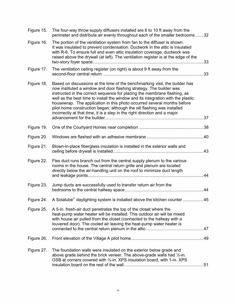
To aid in the placement of draftstopping, IBACOS presented to the builder's superintendent house plans indicating areas where draftstopping was needed. Also, during several site visits, we made suggestions to the superintendent on locations where this technique needed to be done. The typical locations for draftstopping include behind bathtubs, fireplaces, chases on exterior walls, and at chases through the ceiling. In addition, there were many other spots that needed to be draftstopped, especially walls that separated conditioned space from unconditioned space. For example, the attic side face of the walls for the child's loft was sheathed on three sides with oriented strand board (OSB) to meet draftstopping needs (Figure 4). The master bedroom overhang was another area that required draftstopping, although this location did not receive the suggested treatment.
The builder and their framing subcontractor learned about draftstopping and how useful the practice is in controlling air leakage. The fact that it is an inexpensive practice that can use scrap materials and, if properly scheduled with the framer, does not add to labor costs, will make the practice easier to integrate into the builder's general construction practice.
Figure 4. The child’s loft is located in attic space behind the vaulted roof rafters. The OSB sheathing was installed on its outward-facing walls to separate the loft space
from the attic, thereby improving building airtightness and thermal performance.
Mechanical Ventilation Mechanical ventilation systems are not common in new homes in Atlanta, and this will likely remain the case until such systems are required by code. The energy recovery ventilator (ERV) system installed is an efficient system that takes in outdoor air during the winter and preheats it, and takes in outdoor air during the summer and removes humidity from it before it enters the home. Such a system is a good choice for mechanical ventilation of large homes in this climate.
The builder and HVAC subcontractor gained experience in the installation of a mechanical ventilation system. The project took out a lot of the mystery of such a system. Considering that the builder has a
8
custom homes branch that builds homes to the size of this house, greater use of ERVs should occur, especially if the builder effectively markets the indoor air quality benefits.
Thermal Envelope Improvements The most significant thermal envelope improvement in this project is in the windows. Considering that the standard windows used by the builder are double-glazed units with no low-emissivity (low-E) coating, the Peachtree windows used, with an overall heat transfer coefficient (U) value of 0.35 Btu/ft2•h•°F and a solar heat goan coefficient (SHGC) of 0.32, are a major step in energy efficiency. The reduction in heating and cooling loads resulting from the better windows are significant because of the large number of windows in the home.
The benefit of having a smaller-sized HVAC system, because of better windows, is now apparent to the builder. John Wieland Homes now has to work on obtaining a “production level” window at a price that they are comfortable with (a task that they are currently undertaking).
The builder also used radiant barrier roof sheathing for the first time and noted that it helped make the home cooler in summer. They also learned from IBACOS that the foil facing on the sheathing acts as a vapor barrier. Therefore, the air space requirement along the sheathing’s face, required for the radiant barrier to be effective, must also be respected in order to remove potential water vapor in the area. Through the use of low profile ¾-in. fiberglass baffles, an air space was maintained in vaulted roof sections. Once the extra air space requirement was maintained, additional insulation was installed. Two layers of R-13 batts filled up the balance of the vaulted roof cavity, resulting in a R-26 nominal insulation value in 2 x 8 rafter situations.
Through this project, John Wieland Homes learned the benefits of radiant barrier roof sheathing on cooling load reduction. In the process they learned that using this sheathing requires that its air space requirements be maintained.
Durability Improvements In this project, wall durability was enhanced through the use of flashing around windows and doors and the correct use of drainage layers behind the exterior cladding. At a minimum, flexible membrane flashing was installed at the sills of window rough openings in the home. This method protects the most vulnerable area of the window framing from potential moisture problems and is a big improvement from current practice, which relies on housewrap overlapping the framing or no protection at all. Protecting window and door openings from moisture intrusion will improve the durability of the home The window installer became familiar with Dupont’s new Flexwrap product as a result of working on this home. The builder also became familiar with flashing installation techniques and now has an idea of the material cost of one type of these products.
Covering the exterior wall sheathing with a plastic housewrap is often done by the builder, and, if installed properly, it acts as an effective drainage layer. But depending on the exterior cladding, having plastic housewrap as the only drainage layer may not provide enough moisture protection for the wall. Areas that have a synthetic stone cladding require the felt back-up layer because this stone can act as

9
storage for water, which under some vapor pressure conditions, can be passed on to the wood framing in the wall. For this reason, building felt (15 lb.) was placed on sensitive areas of exterior walls in conjunction with the housewrap to give an additional layer of protection (Figure 5).
Builder personnel who worked directly on the project now have a better understanding of the dynamics of moisture movement in walls and how to effectively deal with the properties of different cladding systems. Installation of the additional drainage layer was neither costly nor time-consuming.
.
Figure 5. Building felt was used to provide greater wall moisture protection behind the cultured stone. Membrane flashing was used to cover the sill rough opening. The top
window flange was slipped under the housewrap (above), after the window was installed with its flanges back-caulked (except for the sill flange).
Cost and Performance Considerations
Because this project received a great number of products and technologies for free or at a greatly reduced cost, cost considerations in the project were not as important as in typical construction. This makes it difficult to compare the costs of standard practice against the costs for implementing the improvements. This is especially true in the case of the HVAC system, which was provided at a greatly reduced cost together with the labor for its installation. The only key technology that the builder had to cover was the draftstopping for the home, and the material and labor for this practice for the entire home was less than $500.
The key performance considerations for the project are that it is an energy-efficient home and that it is adequately heated and cooled. Final testing confirmed that the home met energy efficiency goals with a

10
HERS score of 91. It may be that this experience has given John Wieland Homes the confidence to proceed with a community built completely to EarthCraft House standards (which has an energy efficiency component). HVAC commissioning work confirmed that rooms receive adequate conditioning. In the case of the master bedroom, remediation work is being carried out to ensure that this area is comfortable as well.
Future Plans
This project highlighted to the builder several possible ways that they can improve all of their homes, resulting in greater customer satisfaction, fewer callbacks and warranty claims, and overall better quality homes. IBACOS recommends that they consider the following:
Draftstopping to Increase Building Airtightness. Keeping the interior air barrier (drywall) continuous is important for reducing energy consumption, and preventing drafts, condensation, and cold spots. Draftstopping can be used to fill in the gaps in walls and ceilings where there is no drywall present. Because scrap materials are often used, the material cost for draftstopping work is low. The framing subcontractors can do a lot of the work when they initially frame the home, so labor costs also can be low, especially with a little planning before the framing. Room walls adjacent to unconditioned attic space and overhangs deserve particular attention. Because the costs to do this work are small and the benefits are several, the builder should consider adopting this practice in all of its homes, as many other builders have. The chances of this technology being implemented are high.
Optimizing the Number of HVAC Units The number of HVAC units that the builder installs, especially in their larger homes, can be greatly reduced. A zone damper system could be used instead to provide independent temperature control in different areas of the home. In most cases, duct runs would not be much longer, especially if the HVAC units are located centrally. Because one zone damper system costs a lot less than one air handling unit, the builder stands to save money with this practice without sacrificing comfort. Key to optimizing the number of HVAC units is minimizing loads by installing high performance windows and increasing building airtightness. The builder would be able to pay for these with the savings from having fewer air handling units.
The key to implementing this technology is the cooperation of the HVAC subcontractors. As long as they are knowledgeable of zone control systems, comfortable with installing and commissioning them, and transfer the appropriate cost savings to the builder, then this technology will likely be widely implemented. If, on the other hand, the HVAC subcontractor has more to gain financially by selling more air handling units (instead of zone control systems), then the chances of implementation will be a lot lower. It is important that the builder discuss the matter in detail with the HVAC subcontractor.

11
• Appropriate Drainage Plane and Flashing Strategy In this project, IBACOS emphasized to the builder using sheathing wraps over exterior sheathings and flexible membrane flashing around windows and doors. Although the builder commonly uses a plastic housewrap on the exterior sheathing, we recommended that they use a 15-lb. building felt, in combination with the housewrap, behind the synthetic stone on the exterior walls. Because the stone can act as a water storage reservoir, additional protection, in the form of the building felt and the air gap created behind it, will ensure that the wood framing will be exposed to less moisture when vapor drives pressure to the interior.
The builder tends to rely on the plastic housewrap to protect the rough opening of windows. This is, however, an unreliable method because if the wrap is not installed carefully, it may not cover the intended areas. Tyvec’s new FlexWrap membrane flashing was used with some success to provide protection on the rough opening sills. Other less expensive flashing membranes can be used as well. Furthermore, by slipping the top window flange underneath the housewrap above it, water can be drained away from the header rough opening.
IBACOS recommends that the builder use building felt in combination with housewrap behind exterior cladding materials like stucco, brick, and stone applications where there is no air space, or a severely blocked air space behind them. The sills of window rough openings need to be protected from moisture, so we recommend a flexible membrane flashing material. Window flanges should be back caulked (except the bottom one).
The likelihood that all of the mentioned durability measures will be implemented are high given the builder's familiarity with the technologies and the fact that these practices can save them in warranty costs.
Higher Performance Windows The energy savings associated with using windows that have a low-E coating are beneficial. The builder can market to potential customers the added benefit that low-E windows reduce fading of fabrics, and temperature conditions in the home will be more even. Upgrading to these windows is a significant cost, but the load reduction that the windows would bring is key to optimizing the entire HVAC system and thereby reducing overall construction costs and increasing system efficiency. For the builder's Atlanta operations, we recommend windows with values of U-0.35 and SHGC-0.35.
The builder is exploring the costs involved to obtain low-E coated windows. They are confident that these windows can be found at a reasonable price, so implementation should occur in the near future.
12
Greystone Village: Cicero, Indiana
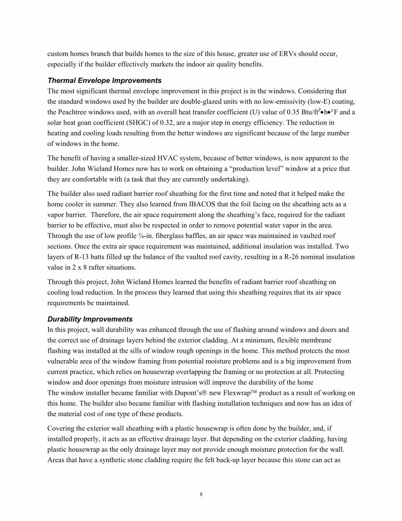
Greystone Village is a 122-unit single-family home ENERGY STAR development catering to retirees and other buyers of affordable housing in Cicero, Indiana, just north of the city of Indianapolis. Coronado Ridge Development, an Indiana-based construction-management and residential-development company, is working with the Estridge Companies of Indianapolis to design and build the community. IBACOS provided design and construction support to ensure that the homes meet the energy efficiency and durability goals established.
Five models are available in the community: two ranches and three two-story models. Each model is manufactured by the same company and set on crawlspace block foundations at the project site. Final integration of space conditioning, ventilation, and other services is done on-site by the developer. Two pilot homes were built first, a ranch (1,400 ft2) and a two-story (1,800 ft2), as sales models and to prototype Building America system concepts (Figure 6).
Figure 6. The ranch and two-story model pilot homes.
Key Technologies
Specifications and design details were developed for all five models to meet energy efficiency and durability goals established by the Building America Program. The energy efficiency goal is a HERS score of 86 (ENERGY STAR level).
Even though five different models were designed, the key technologies and practices that would be used on the homes were the same for all of them, with the two-story units requiring some additional attention. Since the homes were manufactured by Crest Homes, under contract to Estridge and Coronado Ridge, design and specification was coordinated with them in conjunction with on-site requirements.

13
The key technologies used in the homes can be summarized as follows:
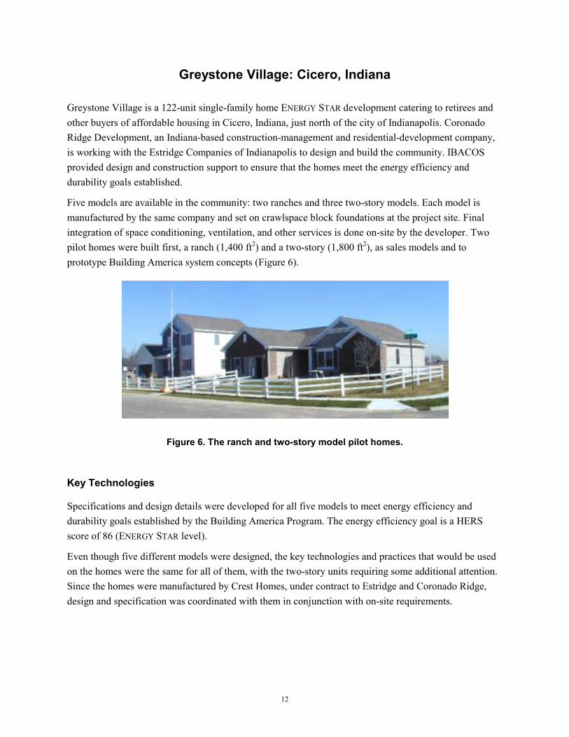
• The crawlspace foundation area was designed and built so that it was inside the building envelope (part of the conditioned space). It was constructed without vents and with a source of conditioned air . Foundation walls and band joists were insulated to R-11. A 6-mil polyethylene sheet was installed to cover the entire floor. Most building airtightness focused on the crawlspace area, penetrations into that area, and its connections with the manufactured modules of the home (Figure 7).
• One downflow furnace with two-stage heating is located within a first-floor mechanical room. The furnace has an efficiency of 91% and is direct vented. To make purchasing simple and more economical, each home will have the same 60,000 Btu/h input furnace. Low-speed heating provides even and consistent temperatures without using the furnace’s maximum capacity.
• Ductwork traveled through the conditioned crawlspace for the ranch model. As per standard manufactured-housing practice, the second-floor return ductwork in the two-story model traveled through unconditioned attic space. Ductwork airtightness measures to reduce duct air leakage include the use of UL 181 approved tape on fiberglass ductboard. Greater use of water-based mastic on other duct joints was needed. Panning of air in floor and wall cavities was not allowed, except in pre-approved circumstances in the wall.
• Different capacity condensing units were used for the ranch and two-story models. A 2.5-ton unit was used for the ranch, while a 3-ton unit was used for the two-story. SEER 10 condensing units were used, mainly because of cost considerations and the number of cooling days.
• To provide mechanical ventilation, a duct was connected from the outdoors to the return-air side of the furnace. Fresh air is drawn into the home by the central fan in the furnace. A mechanical damper in the duct is operated by a ventilation controller, which is set to operate for specific time periods.
• The windows installed, which are the manufacturer's standard product, have good thermal resistance (U-0.38) and low solar heat gain (SHGC-0.29).
• Long-term durability of the building shell was enhanced by the use of a plastic housewrap as a drainage layer.
14
Figure 7. The builder constructed an unvented crawlspace with insulated walls and a source for conditioned air.
Testing and Evaluation Results
The final blower door test, duct leakage tests, and flow plate and air distribution measurements were conducted by IBACOS in November 2001 on both pilot homes.
Building Airtightness Test Results The blower door test was used to determine the air leakage rate of the building envelope for each home. From test data we determined that the ranch home has an air leakage rate of 5.8 ACH at 50 Pa, and the two-story home has an air leakage rate of 5.5 ACH at 50 Pa. The main area where air leakage is occurring is in the crawlspace. The developer is working on correcting the sources for the air leakage.
Air Distribution Test Results Through duct blaster test data we determined that duct air leakage in both homes was high. In both cases the return side leakage accounted for 59% of the total. The return plenum was panned in the floor joist cavity underneath the furnace and was a significant source of duct leakage. Greater attention to sealing efforts would be needed to decrease duct air leakage.
Airflow measurements in the ranch home found that all registers, except for the register in the bathroom of the first floor, had acceptable airflows. In the two-story home, measured airflow in the kitchen and the master bathroom was less than the design flow rate. Reduced airflow was also observed in the return ductwork and grilles. The HVAC subcontractor is examining the problem airflows on the supply and return system.

15
Energy Performance Results IBACOS used the REM/Rate energy-simulation software program to predict loads and annual energy consumption for both homes. The HERS score determined for the ranch model was 87, which exceeds the ENERGY STAR target of 86. For the two-story model, the score was 85. The two-story model did not meet the energy efficiency goal because of high building envelope leakage and return air leakage to the attic. Because this was the builder’s first attempt at building energy efficient homes with manufactured modules, changes to typical practice presented challenges, and the builder deserves to be commended for their effort. The builders are addressing the deficiencies found in both homes to improve the HERS scores and, in the case of the two-story model, to ensure that it obtains a HERS score of 86.
Project Benefits and Lessons Learned
The construction of the pilot homes was a crucial step in integrating the manufactured modules with their crawlspace foundations built on-site, while making the entire home energy efficient. Coordinating this work, which included implementing key technologies, was a challenge and resulted in several lessons learned.
Effective Air Distribution In these homes, duct construction is done partly in the factory and partly on-site. In the ranch home, most of the ductwork was installed on-site. Return air was panned in wall cavities as per standard factory practice. As per specifications, the manufacturer placed return grilles low on the wall instead of high on the wall and therefore limited the amount of air leakage due to panning. Because it was standard practice, the manufacturer was not interested in eliminating the panning of returns in favor of a fully ducted system without increasing the costs. Such a change would also mean that the manufacturer would have to alter some steps of their manufacturing process. Furthermore, the HVAC subcontractor created a return-air plenum in the floor joist space underneath the furnace (in the crawlspace), which was a major source of duct leakage and needs to be addressed in future homes. Combined with the leakiness of the crawlspace area, the leaky return ductwork can draw outside air into the crawlspace and eventually into the supply ductwork. This can lead to increased energy use and homeowner discomfort. The importance of a well-sealed duct system was an important lesson in this project.
In the two-story home, the leaky return air situation is made worse by having an additional floor with its own separate return system. This ductwork system draws return air from ceiling locations on the second floor and takes it to a central return trunk, which then travels down a chase to the first-floor mechanical room where it connects to the return air plenum. This system is installed in the factory, and the on-site HVAC subcontractor does not do any further work on it. Air distribution testing of the performance of the six return-air grilles in the second floor found that four of them were drawing very little air and were essentially ineffective. This has prompted the manufacturer to examine the performance and quality of its second-floor return system.
The air distribution construction techniques were a learning process for personnel of the three groups involved in building the community (i.e., builder, developer, and manufacturer) and the HVAC

16
subcontractor. The duct-sealing guidelines need to be given more attention, with UL 181 duct mastic used throughout the duct system. Panning of return ductwork needs to be avoided as much as possible. The builder, developer, manufacturer and HVAC subcontractor are working together to develop solutions to these issues.
Crawlspace Construction A key technology used to meet the energy efficiency goal for the pilot homes is an airtight building envelope. With the manufactured modules found to be airtight in a benchmarking visit at the construction site, the key to controlling airtightness resided in the construction of the crawlspaces and how well they are integrated with building modules. Testing showed that there were several areas in the crawlspace that required more attention to consistently meet energy efficiency goals and ensure comfortable and well-performing homes.
The bond between the manufactured modules and the crawlspace foundation has to be structurally sufficient and airtight. Attempts to caulk the joint between the foundation and the band joist produced mixed airtightness results. Site personnel now realize the importance of installing sill sealer.
Penetrations leading into the crawlspace were also found to need more attention. Specifically, the ventilation duct penetrated the band joist. Foam spray is needed to fill the space between the duct and the hole cut in the joist. Another key penetration into the crawlspace was its access door, as a lot of air leakage goes around the door and under its sill. Some kind of weather-stripping is needed around the door, and the block sill needs to be filled with mortar or concrete. The importance of more effective airtightness techniques, which are not costly, is now apparent.
Mechanical Ventilation Having a mechanical ventilation system in the project homes was considered an innovation by its builders. A simple and inexpensive passive supply ventilation system was specified. The furnace fan draws outdoor air through dedicated ductwork into the return plenum. A mechanical damper is in place on the duct and is supposed to be controlled by a ventilation controller. The controller regulates how much outdoor air is drawn into the HVAC system in accordance with a preset schedule. When no ventilation air is required, the mechanical damper closes. In both pilot homes it appears that the controller is not functioning as intended and that ventilation air is not being delivered to the home. The HVAC subcontractor is examining the wiring between the controller and the mechanical damper.
The mechanical ventilation system was a learning experience for the HVAC subcontractors because it was the first time they had to install such a system. All the recommended components were installed, but further work is necessary to ensure that they work together correctly.

17
Construction Management The construction of the pilot homes was a crucial step for both the builder and developer in integrating the manufactured modules with their crawlspace foundations built on-site, while making the entire home energy efficient. Coordinating this work was a challenge. Usually there is one party responsible for the construction of a home—the builder. In the case of this project there were three parties—the manufacturer of the home modules, the builder who headed up the design and construction management of the home, and the developer who was responsible for on-site activities. This management and construction structure meant that a lot more construction management coordination was necessary for these homes. Consequently, there was a lot more potential for things to go wrong because of the many opportunities for miscommunication.
Miscommunication most often happened at the site. The requirements related to making the crawlspace airtight, with regard to sealing gaps and penetrations, and proper air distribution techniques, did not appear to make it to the field personnel. It was learned that more effective communication to the site is necessary. With the experience gained in the construction of the pilot homes, performance results should be improved in future homes.
Cost and Performance Considerations Because the homes will be offered for $120,000 to $150,000, construction costs must be controlled. Consequently, the builder examined ways to save money without seriously affecting performance. They saved $450 (or about 9%) by using a Bryant 91% AFUE two-stage furnace over the originally specified 93% AFUE two-stage furnace. This change did not dramatically alter the energy efficiency of the home. A further $200 would have been saved if they would have used a single-stage Bryant 90% AFUE furnace, but they agreed that the two-stage unit was a wiser investment that would result in better homeowner comfort because of the even heating offered at its low heating stage. The HVAC subcontractor priced the mechanical ventilation system very reasonably at $200, so very little cost cutting could be accomplished there. An air filter was found that met the intent of the specification while costing $150 less than the original specification. Building a crawlspace foundation unvented, conditioned, and with walls insulated did not cost dramatically different than the typical vented version.
Future Plans
The pilot homes highlighted to the builder and developer several possible ways that they can improve all of the homes in the 121-unit project so that each meets ENERGY STAR goals. IBACOS has recommended that the following practices be implemented immediately on the pilot homes and all future homes in the community.

18
• Increase Crawlspace Airtightness The crawlspace, a conditioned space, is considered a usable part of the home and needs to be treated as such. This is a new concept for some in the building industry; the crawlspace has always been treated as a buffer space. As a conditioned space, it needs to be made airtight with respect to the outdoors (and not necessarily the house above). Therefore, all penetrations, including ventilation ducts, piping, and access doors must be carefully sealed (with foam, caulk, gaskets, or weather-stripping). Also, the band joist area needs to be more airtight. Sill sealer needs to be used under the plate, and the joint between the plate and the band joist must not have any gaps. All of this airtightness work combined is inexpensive, greatly improves the performance of the home and has to be carried out to ensure that energy efficiency goals are realized.
• Decrease Duct Leakage and Improve Air Distribution Performance Performance testing indicated that air leakage in the duct system, especially in the return system, needs to be reduced. Leakage reduction is critical in stopping air from outdoors and from the attic space (in the two-story situation) from being unintentionally drawn into the return ductwork. Outdoor air drawn into duct leaks increases heating and cooling loads. This energy penalty is reflected in a home’s HERS score, particularly for two-story homes when measured duct leakage is used in analysis. To control duct leakage, UL 181 approved duct mastic should be used to seal all joints between sheet metal and flex ducts. UL 181 tape can be used to seal joints in fiberglass ductboard. The HVAC subcontractor should examine the supply and return ductwork and registers that had low airflows and work with the builder to develop a solution to low air distribution issues.
• Mechanical Ventilation System Operation The HVAC subcontractor needs to ensure that the mechanical ventilation system is operating as intended. In particular the wiring between the controller and the mechanical damper must be complete.
19
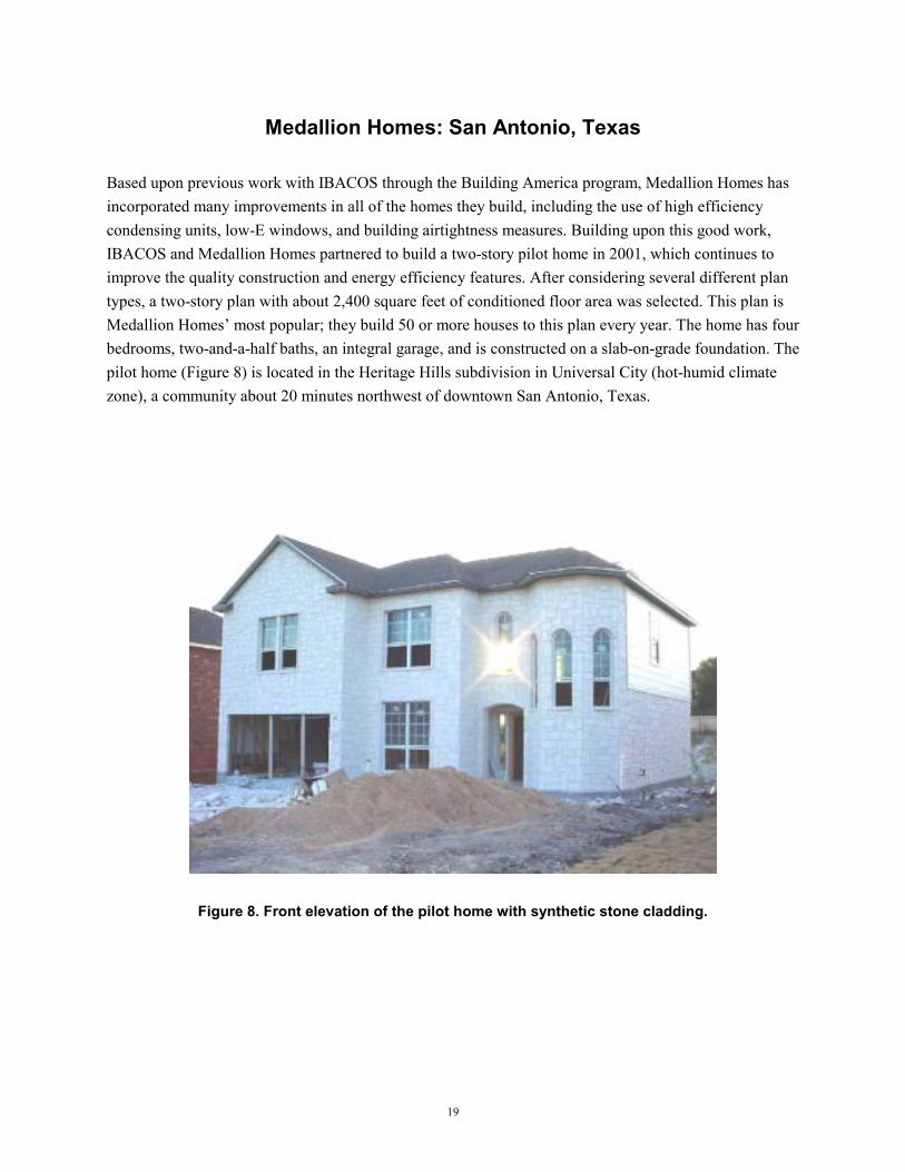
Medallion Homes: San Antonio, Texas
Based upon previous work with IBACOS through the Building America program, Medallion Homes has incorporated many improvements in all of the homes they build, including the use of high efficiency condensing units, low-E windows, and building airtightness measures. Building upon this good work, IBACOS and Medallion Homes partnered to build a two-story pilot home in 2001, which continues to improve the quality construction and energy efficiency features. After considering several different plan types, a two-story plan with about 2,400 square feet of conditioned floor area was selected. This plan is Medallion Homes’ most popular; they build 50 or more houses to this plan every year. The home has four bedrooms, two-and-a-half baths, an integral garage, and is constructed on a slab-on-grade foundation. The pilot home (Figure 8) is located in the Heritage Hills subdivision in Universal City (hot-humid climate zone), a community about 20 minutes northwest of downtown San Antonio, Texas.
Figure 8. Front elevation of the pilot home with synthetic stone cladding.

20
Key Technologies
Specifications were developed for the pilot home to meet energy efficiency and durability goals established by the Building America program. The energy efficiency goal is a HERS score of 90.
The key technologies used in the home can be summarized as follows:
• The house was designed and built with one HVAC unit inside the conditioned space rather than two systems in the attic (as is the typical case for this model). This optimization took into account the heating and cooling loads predicted by detailed analysis. A variable-speed furnace (80% AFUE) and condensing unit (14 SEER) were used. Cooling capacity requirements were reduced from 5 tons to 3.5 tons.
• To improve building airtightness, a great deal of emphasis was placed on draftstopping holes to ensure air barrier continuity. With a strict airtightness goal, it was important to minimize the number of penetrations in the exterior shell.
• Air distribution was optimized through a carefully detailed and engineered duct layout that focused on keeping all of the ductwork within the conditioned space of the house. Ductwork serving the second floor was located in a bulkhead constructed in the second-floor ceiling space. Ductwork airtightness measures to reduce duct air leakage focused on the use of UL 181 approved water-based mastic.
• A passive supply mechanical ventilation system provides outdoor air on a continuous basis to help maintain better indoor air quality. The furnace operates continuously on low speed and draws in outdoor air through a duct connected to the return air plenum. The amount of outdoor air is fixed at 60 cfm by the constant airflow regulator installed.
Testing and Evaluation Results
Final testing work was conducted by IBACOS, the National Renewable Energy Laboratory (NREL), and the builder as a joint effort October 23 to 24, 2001. Tests conducted include a blower door test, a duct pressurization test, flow plate, flow hood, and ventilation air flow rate measurements.
Building Airtightness Test Results The blower door test was used to determine the air leakage rate of the building envelope for the home. At a pressure of 50 Pa, an airflow of 1,600 cfm was induced by the blower door. This value is the equivalent of 4.2 ACH at 50 Pa, or 0.23 natural air changes. This result does not meet the stringent airtightness goal of 3.0 ACH at 50 Pa initially set for the pilot home. There are several possible areas where air leakage could be occurring, including duct penetrations to the mechanical closet and potential leakage paths in the exterior walls.

21
Air Distribution Test Results Duct tests were performed on the HVAC system in the home to quantify the amount of air leakage in the entire duct system. The total duct air leakage was found to be 180 cfm. Medallion wanted to reduce this value, so the HVAC crew plans to come back to the home and improve the ductwork before the homeowner moves in. They will continue to seal the ductwork until the leakage is reduced to 70 cfm.
The flow measuring plate was used to measure the airflow rate at the air handling unit. From measurements, we determined that the airflow rate was 1,260 cfm at cooling speed, slightly less than the manufacturer’s specification of 1,300 cfm. The system should still work well and remove more humidity during cooling operation. We determined that the airflow rate was 565 cfm at low speed, which is very close to the manufacturer’s specification of 570 cfm. This furnace operates continuously on low speed for ventilation. The fan was measured using 70 W of electricity at this speed.
The flow hood was used to measure the airflow at each floor, wall, and ceiling register when the air handling unit was running at cooling speed (high). From test data, we determined that the duct system was properly balanced, according to the design for the pilot home.
Energy Performance Results IBACOS used the REM/Rate energy simulation software program to predict loads and annual energy consumption for the home. The HERS score determined for the home was 90, which meets the target of 90. Even though some of the performance targets were just missed, the home performed well enough to meet the established energy efficiency goal.
Project Benefits and Lessons Learned
Even though the builder has experience building energy-efficient homes, this second pilot home project was a good learning experience for them. The areas of HVAC system optimization, mechanical ventilation, and building airtightness stand out as project highlights.
HVAC Optimization All of the builder’s homes that have more than 2,300 ft2 of conditioned floor area typically have two mechanical systems located in the attic. One system serves the second floor, while the other serves the first floor. Therefore, most of the ductwork for these homes is located in the attic, where it is exposed to extreme outdoor conditions. Through IBACOS’s initial pilot home with the builder, the builder learned that bringing the mechanical equipment and ductwork inside the home reduces the load and energy consumption of the house by almost 25%. This one improvement alone can enable the builder to downsize from two mechanical systems to one system on houses in the range of 2,300 to 2,800 ft2 floor space.
In this current pilot home project, IBACOS worked closely with the builder’s design staff and mechanical contractor to develop a comprehensive duct system design. Because cooling is the priority in that climate, all supply and return diffusers throughout the home are located in the ceiling or high on the walls, contributing to better air distribution. Given the particular configuration of the plan, the best location for a

22
mechanical closet was on the first floor between the house and garage. From this location, ductwork for the first floor spaces was integrated into the floor structure for the second floor. All of the diffusers for the first floor are located in the ceiling.
A bulkhead was created above bathrooms and closets on the second floor to create a duct distribution plenum for the second-floor spaces. The second-floor ceiling was raised to 9 ft, while the ceiling at the bulkhead was dropped to 7 ft 8 in., leaving more than 12 in. for duct distribution. Most of the diffusers for the second floor are located at high sidewalls, at the edges of the bulkhead. The diffusers are correctly sized to ensure that the conditioned air is effectively distributed in the room.
These changes called for a new design that, as is often the case, was a challenge to implement in the field. Because the field crew was not familiar with the new practices required, they initially had some difficulty understanding the ductwork design until IBACOS visited the site and clarified the design. After IBACOS trained the field crew on the techniques needed to achieve the new design, the crew successfully installed a ductboard supply trunk running horizontally through the bulkhead in the second floor, almost the entire length of the house (Figure 9). All the supply duct runs came off this trunk at locations near each diffuser.
Attention to duct sealing was accomplished with the use of UL 181 approved, water-based mastic sealant. Though air leakage in the duct system was higher than the target value, the system should still perform effectively. Airflow measurements confirmed that enough air is being delivered to rooms.
A high-efficiency condensing unit and furnace with a variable-speed blower complemented the duct layout. The furnace fan can operate on low speed when no conditioning is needed and distribute the fresh outdoor air provided by the mechanical ventilation system. Because of cost considerations, a zone control system was not installed.
The home’s only thermostat resides in the study on the second floor. To control the high humidity experienced in San Antonio, a Carrier programmable thermostat with dehumidification control was installed in the pilot home. The Thermidistat™ control device can vary the runtime and airflows of the cooling system to provide maximum latent load removal and keep humidity levels comfortable.
The pilot home project demonstrated that a single HVAC system, within the conditioned space, is a workable design. It can also save the builder in construction costs.

23
Figure 9. The final duct installation incorporated a horizontal duct board trunk in the bulkhead with flex duct runs perpendicular to this main trunk.
Mechanical Ventilation Since the builder began working with IBACOS in 1998, they have begun to install mechanical ventilation systems in all of their homes. The system we recommended is an energy efficient variable-speed fan in the furnace that can be used to provide mechanical ventilation and is a cost effective solution.
The fan will be set to run continuously at low speed whenever the thermostat is not calling for heating or cooling. At this low-speed setting, the furnace fan moves about 500 cfm of air while using about 100 W of electrical power. This is less power than most ERVs or HRVs, so it is an economical option for providing ventilation air, with respect to fan power consumption. A 5-in. round duct was routed from a fresh-air intake at the second-floor band joist and connected to the return plenum near the furnace. This fresh-air duct has been equipped with a 60 cfm constant airflow regulator, which is designed to maintain a flow of 60 cfm of fresh air whenever the furnace fan is operating, even at varying speeds (Figure 10). When the furnace fan operates, fresh air will be drawn into the house through the fresh-air duct, mixed with house air in the return plenum, drawn through the pleated media filter, conditioned by the central system, and then distributed throughout the house.
Medallion Homes valued learning how to develop an appropriate mechanical ventilation strategy. This pilot home project built on the lessons learned from the first project so that the builder developed an improved to provide mechanical ventilation. The builder's personnel and HVAC subcontractor also gained a great deal of knowledge on mechanical ventilation in the process.

24
Figure 10. A fresh-air intake duct with a constant airflow regulator runs from the outside to the return plenum. The furnace operates continuously on
low speed to provide whole-house ventilation.
Building Airtightness Key to meeting the energy efficiency goal for this pilot home is having an airtight building envelope. Medallion Homes’ standard construction practices include constructing an airtight building shell. For this reason, they also install a mechanical ventilation system in all of their homes.
The builder currently seals all penetrations in exterior walls and at the insulated ceiling with expanding foam sealant. All windows and doors are also sealed with low-expansion foam. All bottom plates are caulked to the subfloor, and the drywall functions as the main air barrier in the homes.
Because the drywall is not continuous throughout the home, IBACOS specified draftstopping in several locations in the pilot home to make the air barrier complete. Draftstopping was specified for the walls behind, and the lid above, the direct vent fireplace unit. Draftstopping was also specified for behind the tub and shower surround in the second-floor bathroom, and behind the jacuzzi tub and shower stall in the master bathroom. Finally, draftstopping was specified at the 9-ft ceiling height above the second-floor bulkhead (Figure 11). This will create a continuous air barrier at the 9-ft ceiling height across the second floor, with fewer penetrations for air diffusers and ceiling lights. IBACOS reviewed all of this work with the builder's construction staff and trades-people before construction, and with the site supervisor during the framing stage.
All of the draftstopping was installed at the ceiling of the second-floor bulkhead, but the draftstopping in the walls did not get installed. The purchasing department did not get the appropriate materials on-site, so the trades and the site supervisor had to move forward without it. This miscommunication resulted in the pilot home not being able to reach the airtightness target set for the pilot home.

25
Figure 11. Draftstopping applied at the top of the second-floor bulkhead.
In any case, the builder appreciates the value of this construction technique and is committed to draftstopping all of their homes. They will revise their purchasing process to accommodate this change in practice.
Cost and Performance Considerations With a HERS score of 90, the builder is pleased that the pilot home met the energy efficiency requirements established. This rating would not have been met if the ductwork in the home was not all contained within conditioned space.
The builder was able to track most of the costs for upgrading the model to the improved standard. There were significant cost savings through the optimized HVAC system strategy. One less HVAC unit reduced cooling capacity dropped from 5 tons to 3.5 tons, and savings were substantial. The builder decided to spend these savings on the upgraded two-speed furnace, the ventilation system, draftstopping for building airtightness, and duct-sealing measures. Unfortunately, money was also spent to fix learning curve problems. In all, the builder reports that the pilot home project cost an additional $300. IBACOS believes that there were enough remediation costs associated with the home that, if the design was followed correctly from the start, the builder would have ended up saving construction costs.

26
Future Plans
This two-story pilot home project suggested to the builder several possible ways of improving all of their homes to result in greater customer satisfaction, fewer callbacks and warranty claims, and overall better-quality homes. IBACOS recommends that they consider the following:
• HVAC Optimization Strategy Duct system testing in the pilot home again confirms that the total load on the mechanical system is reduced dramatically when the ductwork is located in the house, rather than in the attic. Reworking the duct system for the builder's houses would be a significant design effort. Most of its homes do not have much space to accommodate a mechanical closet and duct distribution. A systems integration design process would need to look at integrating the ductwork into the structure of the houses. The performance benefits certainly justify this redesign effort. This improvement will enable the builder to downsize the mechanical equipment on all of its homes, and in many cases, use one system instead of two. This could provide significant cost savings for the builder, which would enable it to make other improvements to its houses.
• Improved Mechanical Ventilation The variable-speed fan in the furnace is a good way of providing mechanical ventilation. The furnace fan operates on low speed, pulls a controlled amount of fresh air from the outside, filters and conditions the air, and distributes the fresh air throughout the home. This system gives the builder maximum value from the high-efficiency HVAC equipment, and provides another good marketing story and competitive advantage for the builder. This strategy should be implemented in more of the builder’s homes.
• Draftstopping to Increase Building Airtightness Medallion Homes is committed to building airtight homes, and understands the benefit of using draftstopping. The next step is for them is to work through the logistical issues of implementing this technique in the field.

27
Farm Development: Dutchess County, New York
Pilot Home 2001
Farm Development Corporation’s pilot home demonstrates quality and energy efficiency (Figure 12). The home, which will act as a sales model for Farm for several years, is on a hill overlooking a valley in their Dalton Farm community in Dutchess County, New York (cold climate zone, near Poughkeepsie). Farm received support from the Owens Corning System Thinking Builder Program in conjunction with Building America.
The home has a full basement with a 9-ft ceiling. Its two stories provide a total of 3,360 ft2. The garage is also heated and will act as the primary sales center in the home. The home features a number of Owens Corning products, including cultured stone, vinyl siding, insulation, asphalt shingles, and acoustic studs.
Figure 12. Front of pilot home with Owens Corning cultured stone and vinyl siding.
Key Technologies
Specifications and design details were developed for the home to meet energy efficiency and durability goals established by the Building America Program. The minimum energy efficiency goal is a HERS score of 86.
IBACOS determined the key technologies and practices that would be used on the home based on the goals established and then consulting with the builder and Owens Corning. The builder provided clear leadership to their subtrades on meeting the requirements.
28
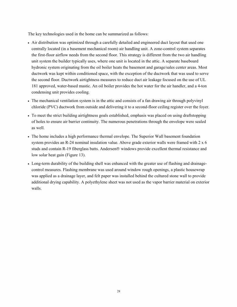
The key technologies used in the home can be summarized as follows:
• Air distribution was optimized through a carefully detailed and engineered duct layout that used one centrally located (in a basement mechanical room) air handling unit. A zone-control system separates the first-floor airflow needs from the second floor. This strategy is different from the two air handling unit system the builder typically uses, where one unit is located in the attic. A separate baseboard hydronic system originating from the oil boiler heats the basement and garage/sales center areas. Most ductwork was kept within conditioned space, with the exception of the ductwork that was used to serve the second floor. Ductwork airtightness measures to reduce duct air leakage focused on the use of UL 181 approved, water-based mastic. An oil boiler provides the hot water for the air handler, and a 4-ton condensing unit provides cooling.
• The mechanical ventilation system is in the attic and consists of a fan drawing air through polyvinyl chloride (PVC) ductwork from outside and delivering it to a second-floor ceiling register over the foyer.
• To meet the strict building airtightness goals established, emphasis was placed on using draftstopping of holes to ensure air barrier continuity. The numerous penetrations through the envelope were sealed as well.
• The home includes a high performance thermal envelope. The Superior Wall basement foundation system provides an R-24 nominal insulation value. Above grade exterior walls were framed with 2 x 6 studs and contain R-19 fiberglass batts. Andersen windows provide excellent thermal resistance and low solar heat gain (Figure 13).
• Long-term durability of the building shell was enhanced with the greater use of flashing and drainage-control measures. Flashing membrane was used around window rough openings, a plastic housewrap was applied as a drainage layer, and felt paper was installed behind the cultured stone wall to provide additional drying capability. A polyethylene sheet was not used as the vapor barrier material on exterior walls.

29
Figure 13. R-19 batt insulation filled the cavities of the Superior Wall foundation (insulation gaps and band joists were filled in later). Because the drywall finish in the basement was extremely
important, a stand-alone frame wall was set in front of the foundation.
Testing and Evaluation Results
The final blower door test and flow plate and air distribution measurements were conducted by IBACOS in November 2001. At the predrywall stage, a duct blaster test was conducted to determine duct leakage.
Building Airtightness Test Results The blower door test was used to determine the air leakage rate of the building envelope for the home. From final test data, we determined that the home has an air leakage rate of 4.1 ACH at 50 Pa. This result, by considering testing tolerances, meets the airtightness goal of 4.0 air changes per hour, or less. The induced flow rate was 3,480 cfm at 50 Pa. The final house volume was 50,950 ft³.
There did not appear to be any areas where major air leakage was occurring. Only smaller areas showed leakage, including the attic hatch, the weather-stripping around exterior doors, and the numerous penetrations through the building envelope. Clearly the draftstopping work performed by the builder helped the home to meet the airtightness goals established.
Air Distribution Test Results Duct blaster testing at the predrywall stage to determine duct leakage of the ductwork and the air handling unit found only 260 cfm of leakage in total. Considering the amount of ductwork in the home, especially sheet metal, this result is very good, even though it exceeds the original target.
Based on IBACOS’ recommendation, the HVAC subcontractor used UL 181 approved, water-based mastic, instead of oil-based mastic, on duct joints with foil-faced tape except for longitudinal seams in oval ducts where foil-faced tape was allowed (Figure 14).

30
Figure 14. On the left is an example of the careful mastic sealing done on a return trunk line that
runs beside a sealed and insulated supply trunk. On the right are two return branches that terminate in the high wall on the first floor with mastic sealant at joints and foil-faced tape on the
longitudinal seams of the sheet metal oval ducts.
From airflow measurement data we determined that all registers met design airflow, except the one in a bedroom, where the flow was 33% low. Because there are balancing dampers at each branch duct takeoff, airflow will be rebalanced in the second-floor system to increase the airflow to this register.
Based on flow plate measurement data, we determined that the air handling unit moved 1,180 cfm of air in heating mode and 1,330 cfm in cooling mode, although the value found by adding all register flows was about 40% higher. Based on standard air delivery specifications, a 4-ton air handling unit is expected to move about 1,600 cfm of air at high speed. IBACOS is examining both sets of measurement equipment to try to explain the discrepancy.
Energy Performance Results IBACOS used the REM/Rate energy simulation software program to predict loads and annual energy consumption for the home. The HERS score determined for the home was 88, which exceeds the target of 86 and qualifies the home for ENERGY STAR certification. Considering that this is the first home that the builder attempted to build to a higher level of energy efficiency, the fact that they easily met the target is very encouraging. The builder is currently in discussion with the New York State ENERGY STAR program to have all of their homes become ENERGY STAR certified. With the success of the pilot home project, such a goal will now be a lot more easily attained.
Project Benefits and Lessons Learned
The pilot home project was a great learning experience for the builder. Not only did those individuals directly involved in its construction gain an education in building science and quality construction, builder management brought other site superintendents to training and testing sessions so they too could

31
learn. Improvements in the areas of air distribution and HVAC optimization, building airtightness, mechanical ventilation, thermal envelope performance, and envelope durability stand out as project highlights.
Air Distribution and HVAC Optimization Having one air handler for a home the size of the pilot is a significant change for the builder's HVAC subcontractors. They would normally install a separate air handling unit in the attic to serve the second floor. Other builders might install a separate system in the attic to serve the master bedroom. It is clear that measures to improve the thermal performance of the home (mainly through higher performance windows and increased building airtightness) reduced the heating and cooling loads and helped to allow the use of only one air handling unit.
Having only the one air handling unit has forced the subcontractors to concentrate more on the delivery of air to rooms. They accomplished this by following the detailed duct layout. They wisely followed details like centrally positioning supply registers in bedrooms (between 6 and 10 ft away from the perimeter wall) (Figure 15) and installing balancing dampers at branch duct takeoffs. At the request of the subcontractor, register placement followed common practice so that on the first floor, supply registers will be positioned in the floor and returns will be kept high in the wall. On the second floor, supply registers will be placed in the ceiling, and returns will be placed low on interior walls.
The zone damper system works well with two dampers used to control the first floor and one damper located in the main supply trunk that runs up the central chase to the attic. All ductwork in the attic was insulated to a minimum of R-6, and the subcontractor went even further by deciding to insulate supply ductwork (and some return ductwork) that traveled through conditioned space. Panning of return air through wall and floor joist cavities was not permitted. The subcontractors became familiar with the best (and less toxic) mastic sealant to use to seal duct joints. Considering that this was their first attempt, they performed admirably.
This air distribution and equipment optimization strategy showed the builder and their HVAC subcontractor that there is an alternative to area zoning other than using individual HVAC units for each zone. Such a strategy, although it requires some design and engineering effort upfront and familiarization with zone control systems, benefits the builder because fewer HVAC units are needed, which translates into lower construction costs.

32
Figure 15. The four-way throw supply diffusers are 6 to 10 ft away from the perimeter and
distribute air evenly throughout each of the smaller bedrooms.
Building Airtightness To meet the energy efficiency goal for the pilot home, building airtightness is critical. The air barrier strategy is focused on using drywall as the main air barrier. But in order to be effective, an air barrier must be continuous. Because drywall is absent from several exterior wall and ceiling locations, draftstopping must be used to make up for the gaps in the air barrier. In addition, penetrations through the air barrier should be sealed. Plastic housewrap placed on the exterior sheathing also helps to increase overall airtightness. The use of draftstopping to control air leakage is a new technique for the builder, who used their own laborers for most of this work.
IBACOS presented a checklist that detailed areas needing draftstop sheathing to the site superintendent. During our site visits, we identified to the superintendent additional areas where draftstopping was needed. The locations we identified for draftstopping include behind bathtubs, shower enclosures, fireplaces, and chases on exterior walls and through the ceiling. Several spots that separated conditioned space from unconditioned space required draftstopping as well. Blower door test results confirm that the builder successfully carried out the prescribed airtightness techniques.
The builder gained additional knowledge about draftstopping through this project. They know that it is an inexpensive practice that can save them a lot of problems related to cold and drafty spots in rooms. The practice would also help them meet ENERGY STAR requirements.
Mechanical Ventilation The use of mechanical ventilation in their homes was a new practice for the builder, but with an airtight building envelope, ventilation became a necessity. A simple supply ventilation system (Figure 16) with air delivery to the ceiling of the two-story foyer (Figure 17) was specified and installed. A Fantech FR100 in-line fan draws air from outside, through PVC piping. This system has a low first cost.
Air temperatures and humidity levels are being monitored to evaluate the impact of the ventilation air supply on the space conditions.
The builders are now more familiar with the benefits and necessity of mechanical ventilation.

33
Figure 16. The portion of the ventilation system from fan to the diffuser is shown. It was insulated to prevent condensation. Ductwork in the attic is insulated with R-6. To ensure full and even attic insulation coverage, ductwork was raised above the drywall (at left). The ventilation register is at
the edge of the two-story foyer space.
Figure 17. The ventilation ceiling register (on right) is about 9 ft away from the second-floor central return.

34
Thermal Envelope Improvements There are two significant thermal envelope improvements that the builder instituted in the pilot home. The first is the windows, which have been upgraded to Andersen 400 series windows with a low-E coating (U-0.35, SHGC-0.29). This window is an improvement over the normally used standard double-glazed window unit with no low-emissivity coating. The reduction in heating and cooling loads resulting from the better windows is significant because of the large number of windows in the home. The other area of significant thermal performance improvement is the foundation. Although the builder typically uses the Superior Wall foundation system on all of their homes, they usually leave the cavities of the system uninsulated. Adding R-19 batt insulation in the cavities greatly diminishes heat loss through the foundation.
These thermal performance improvements were vital in reducing the size of the HVAC system (especially because of the better windows). The builder realizes that the cost savings associated with using one zone-controlled air handling unit can be used to pay for the thermal performance improvements.
Durability Improvements Building envelope durability was enhanced through the use of flashing around windows and doors and the correct use of drainage layers behind the exterior cladding. Flexible membrane flashing was installed at the sills of window rough openings and then over the flanges of the windows, first over the window jambs and then the headers. Plastic housewrap overlapped the flashing to create an effective drainage layer. These techniques will protect window and door openings from moisture intrusion.
Farm Development typically covers the exterior wall sheathing with a plastic housewrap. If installed properly, the housewrap acts as an effective drainage layer. Depending on the exterior cladding, however, having plastic housewrap as the only drainage layer may not provide enough moisture protection for the wall. For this reason, building felt (15 lb.) was placed on sensitive areas of exterior walls in conjunction with the housewrap to provide an additional layer of protection. Areas that have a synthetic stone cladding require the felt back-up layer because this stone can act as a water reservoir, which under certain conditions can pass moisture to the wood framing in the wall. The felt creates an air space that hinders the interior part of the wall from getting wet and therefore increases its drying potential.
The builder now understands the principles and dynamics of moisture movement in walls and how to effectively deal with the properties of different cladding systems. Installation of the additional drainage layer was not costly nor time-consuming.
Cost and Performance Considerations
The builder built their first home that meets ENERGY STAR requirements (HERS 86) by carefully following the recommendations made by IBACOS. With a HERS score of 88, they met the requirements by a comfortable margin. This is encouraging for them, especially if they consider building all of their homes to that standard. It also means that if they find it necessary to reduce costs when building future energy efficient homes, they can fine-tune designs by knowing the level of construction effort expended on the pilot home and what was the associated energy efficiency result.

35
Because this home is a specially designed and built model, the builder was able to track some of the costs for upgrading it to the ENERGY STAR level. The biggest upgrade cost was for the windows. This amounted to an extra $6,000 for Andersen windows with a low-E coating. With Andersen introducing a less expensive low-E coated window in 2002, this incremental cost could fall to between $1,000 and $2,000 for the number of windows in the pilot home. The builder realized about $2,500 in construction cost savings by going with the optimized HVAC strategy. This optimized strategy includes the extra duct sealing work performed, but it does not include the heating system for the basement, which was a special feature for this home. The builder calculates that they spent an extra $800 for more insulation. This includes the R-19 batts in the cavities of the foundation system and upgrading attic insulation levels to R-38 with batts. This compares with the normal practice of leaving the interior part of the foundation system uninsulated and using R-30 blown-in insulation in the attic. Because the original requirement for foundation system insulation was R-11, the builder could have saved some money without jeopardizing their ENERGY STAR rating (but they wisely choose to insulate with R-19 and play it safe). The additional cost associated with the mechanical ventilation system was $200, although the fan and controller were both supplied by IBACOS. Draftstopping and additional airtightness work cost about $500.
The bottom-line upgrade cost for the builder to build the pilot home was $5,000. This cost could easily be reduced to zero on future homes if low-E window costs fall as predicted, if the builder optimizes the insulation values needed to meet ENERGY STAR and if draftstopping and additional airtightness work could be done more productively.
Future Plans
The pilot home project suggested several possible ways that the builder can improve all of their homes, resulting in more energy-efficient and overall better quality homes that produce greater customer satisfaction and fewer callbacks and warranty claims. IBACOS recommends that they consider the following items.
The pilot home proved that the trend to have more HVAC units in a home is unjustified. One air-handling unit, with a zone damper system, is suitable for most large homes. Depending on the size and configuration of the home, a zone control system may not be necessary. Because this strategy is a proven concept in the builder's largest production home built to date, adapting this practice to smaller homes would pose little problem. Long-term monitoring over four seasons will evaluate space temperatures and energy consumption to substantiate performance claims.
Air distribution in the home was greatly improved with effective duct-sealing practices to ensure that air is delivered to and drawn from its intended locations. To make this work, all air must travel through ductwork, so panning of return air is not an option. These practices should be adopted as a strategy for all of the builder's homes. If the builder does proceed with ENERGY STAR certification as standard practice, then the strategy will have to be adopted.

36
• Draftstopping to Increase Building Airtightness Keeping the interior air barrier (drywall) continuous is important for reducing energy consumption and preventing drafts, condensation, and cold spots. Draftstopping can be used to fill in the gaps in walls and ceilings where there is no drywall present. Such work is critical in the climate in which the builder works. The greater use of scrap materials in this practice needs to be considered; more coordination of labor will bring the costs to do this work down. Even though the builder has adopted draftstopping at rooms over garages, they need to adopt this practice in a greater number of locations in a home as prominent as the pilot home project. The chances of this technology being fully implemented are high.
• Mechanical Ventilation Strategy With the builder able and interested in increasing the airtightness of their homes, there is an increased need for mechanical ventilation. IBACOS has presented to the builder management different ventilation system options available, including heat-recovery ventilators, supply fans, exhaust fans, and passive supply systems. We recommend that the builder choose one of the systems for widespread implementation as soon as possible. IBACOS can provide guidance on the most applicable system.
• Increasing Building Durability As a result of earlier discussions, the builder has instituted window flashing detailing to prevent moisture intrusion issues in that area (Figure 18). The integration of the flashing with their plastic housewrap was also discussed. In the course of the pilot home project, IBACOS recommended that they use a 15-lb. building felt, in combination with the housewrap, behind synthetic stone on exterior walls. Because the stone can act as a water reservoir, additional protection, in the form of the building felt and the air gap created behind it, will ensure that the wood framing behind that will be exposed to less moisture when vapor pressure drives moisture toward the interior and that the wall will dry out more easily.
IBACOS recommends that the builder use building felt in combination with housewrap behind exterior cladding materials like stucco, brick, and stone applications where there is no air space, or a severely blocked air space behind them. They should continue their flashing practices around windows and doors.
It is very likely that all of the mentioned durability measures will be implemented by the builder because they have implemented many measures already. They also understand that these practices can save them a lot in warranty costs.

37
Figure 18. Based on discussions at the time of the benchmarking visit, the builder has now instituted a window and door flashing strategy. The builder was instructed in the correct
sequence for placing the membrane flashing as well as the best time to install the window and its integration with the plastic housewrap. The application in this photo occurred several months
before pilot home construction began; although the sill flashing was installed incorrectly at that time, it is a step in the right direction and a major advancement for the builder.
• Increasing Thermal Envelope Performance Whether or not the builder decides to build all of their homes to the ENERGY STAR level, they should consider widespread thermal envelope improvements. Using high-performance (low-E coated) windows is a must for the climate in which they build. Attic insulation levels need to be increased from their R-30 standard, and Superior Wall foundation systems should be insulated to a minimum of R-11 on the inside. All of these improvements can be easily marketed to consumers, especially during times of high energy prices. Because the builder now knows a way to more effectively communicate the benefits of such improvements, through the use of energy simulation software, integrating thermal envelope improvements into their standard construction specification should happen quickly.

38
ContraVest Properties: Tucson, Arizona
ContraVest Properties has been a homebuilder in the Tucson, Arizona, region (hot-dry climate zone) for more than 10 years. The company builds a wide range of homes, including large custom homes and small houses for first-time home buyers. ContraVest Properties has distinguished themselves from their competitors by focusing on energy efficient construction.
ContraVest Properties has purchased more than 100 home sites in the Community of Civano. They are building a series of seven different house plans, all on slab-on-grade foundations, ranging in size from 1,300 square feet to 1,800 square feet of conditioned floor area. Some of the houses are Courtyard Homes (Figure 19), which are placed on narrower sites, while the Desert Country Homes are spacious, one-story designs placed on slightly larger lots. All of these houses were specifically designed by ContraVest Properties for the Community of Civano and are designed to comply with the sustainability and energy requirements of the Civano Code.
Figure 19. One of the Courtyard Homes near completion.
Key Technologies
IBACOS worked with ContraVest Properties to develop specifications and a systems engineering design for all seven of their house plan types that conform to the requirements of the Civano Code. The Civano Code has two main requirements that all of the homebuilders must comply with: that they build homes that are 50% more energy efficient than the Model Energy Code (heating, cooling and water heating energy consumption only) and meet the beneficial use of solar requirements as defined by the Civano Code.

39
IBACOS determined the key technologies and practices that would be used on all the builder's houses in the community based on established goals. These key technologies and practices were refined during design discussions with the builder's management and construction supervisors. The builder was eager to meet the performance goals cost-effectively using techniques familiar to local trades. Given their input, the final specifications were tailored to meet the builder's needs.
The key technologies used in all the homes can be summarized as follows:
• Thermal performance of the above grade components of the building envelope was improved. Exterior walls were framed with 2 x 6 studs and the cavities were insulated with R-19 blown in place fiberglass. The walls were sheathed with R-3 expanded polystyrene over the entire wall area and finished on the exterior with traditional stucco. Aluminum frame windows with double-pane, low-E glass were used and properly flashed when installed in the walls. Ceilings were insulated with R-38 blown-in fiberglass insulation.
• To improve building airtightness, the drywall was installed as an airtight system. On the exterior walls, the drywall was glued at top and bottom plates and around all the windows and doors. At interior walls on the second floor, the drywall was glued to the top plates. Locations in the exterior walls where no drywall is installed (behind tubs, shower surrounds, duct chases, etc.) were pre-insulated and sealed with draftstopping by the framing crew. The builder also worked with a local airtightness contractor to seal all penetrations in exterior walls and ceilings, including wiring and plumbing penetrations, ceiling fixtures, and window and door rough opening gaps, with expanding foam.
• The community's sustainability code requires that all of the houses incorporate some beneficial use of solar energy to reduce the energy demands for heating, cooling, and domestic water heating. The code outlines an extensive list of devices and methods that may be used to achieve compliance with this requirement, including solar thermal space heating or domestic water-heating systems, photovoltaic power systems, solar daylighting systems, a solar food dehydrator built into the structure, and passive building heating for the winter through the use of optimal window shade structures and orientation. The builder used a solar daylighting system to meet this requirement.
• Energy-efficient mechanical equipment was installed to increase the energy efficiency of the home. A heat pump unit with 12 SEER cooling performance and 7.5 Heating Seasonal Performance Factor (HSPF) heating performance was used. The unit is located on the roof of the home.
• All of the duct runs use insulated flex duct, which is meticulously sealed with duct mastic at all connections. These duct runs are located in the attic and buried with blown-in fiberglass insulation. The main duct plenums, which penetrate through the roof to the heat pump unit above, are made with insulated sheet metal duct and sealed with duct mastic. A central return with jump ducts to the bedrooms was used to minimize the length of return duct, while still equalizing pressures throughout the house while the system is operating.
• An energy efficient heat-pump water heater with an Energy Factor of 2.5 is being installed in all the houses. This unit will help keep the house cool throughout the summer, as it pulls heat from the house

40
and rejects the heat into the domestic hot water tank. The mechanical ventilation system for the house was also integrated into the heat-pump water heater. A portion of the intake air for the heat-pump water heater is drawn from outside; the rest is drawn from the house. After heat is extracted from this mixed air stream, the air is ducted into the return plenum of the central air handling unit. Therefore, the heat-pump water heater pre-cools the fresh air intake during the hot and long Tucson summer.
• Long-term durability of the building shell was enhanced with the greater use of flashing and drainage-control measures. An adhesive membrane was used to flash around window (Figure 20) and door rough openings, and intersections between the roof and wall were flashed.
Figure 20. Windows are flashed with an adhesive membrane.
Testing and Evaluation Results
The final blower door test was conducted by Tucson Electric Power, with guidance from IBACOS, on November 12, 2001, for the first model home, a Courtyard model. A duct pressurization test was conducted on this home in September, after the ductwork was installed but before the air handling unit was installed. Flow plate measurements and flow hood measurements were conducted at the same time as part of HVAC system evaluation and commissioning work.
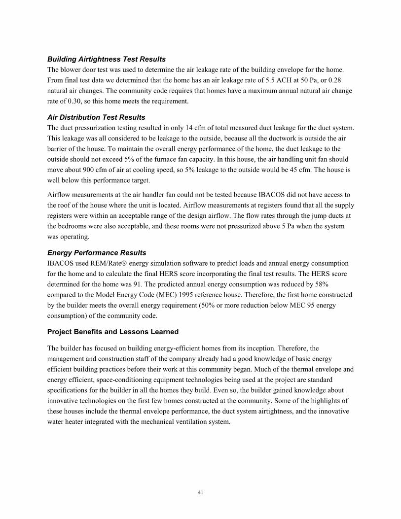
41
Building Airtightness Test Results The blower door test was used to determine the air leakage rate of the building envelope for the home. From final test data we determined that the home has an air leakage rate of 5.5 ACH at 50 Pa, or 0.28 natural air changes. The community code requires that homes have a maximum annual natural air change rate of 0.30, so this home meets the requirement.
Air Distribution Test Results The duct pressurization testing resulted in only 14 cfm of total measured duct leakage for the duct system. This leakage was all considered to be leakage to the outside, because all the ductwork is outside the air barrier of the house. To maintain the overall energy performance of the home, the duct leakage to the outside should not exceed 5% of the furnace fan capacity. In this house, the air handling unit fan should move about 900 cfm of air at cooling speed, so 5% leakage to the outside would be 45 cfm. The house is well below this performance target.
Airflow measurements at the air handler fan could not be tested because IBACOS did not have access to the roof of the house where the unit is located. Airflow measurements at registers found that all the supply registers were within an acceptable range of the design airflow. The flow rates through the jump ducts at the bedrooms were also acceptable, and these rooms were not pressurized above 5 Pa when the system was operating.
Energy Performance Results IBACOS used REM/Rate energy simulation software to predict loads and annual energy consumption for the home and to calculate the final HERS score incorporating the final test results. The HERS score determined for the home was 91. The predicted annual energy consumption was reduced by 58% compared to the Model Energy Code (MEC) 1995 reference house. Therefore, the first home constructed by the builder meets the overall energy requirement (50% or more reduction below MEC 95 energy consumption) of the community code.
Project Benefits and Lessons Learned
The builder has focused on building energy-efficient homes from its inception. Therefore, the management and construction staff of the company already had a good knowledge of basic energy efficient building practices before their work at this community began. Much of the thermal envelope and energy efficient, space-conditioning equipment technologies being used at the project are standard specifications for the builder in all the homes they build. Even so, the builder gained knowledge about innovative technologies on the first few homes constructed at the community. Some of the highlights of these houses include the thermal envelope performance, the duct system airtightness, and the innovative water heater integrated with the mechanical ventilation system.

42
Thermal Envelope Improvements The main lesson learned about the thermal envelope in these houses is that a high level of energy efficiency can be achieved while using mostly conventional construction practices. The above-grade walls were framed with 2 x 6 studs in order to have a deeper cavity to allow for more insulation (Figure 21). The builder already uses this framing system as standard practice, partly for improved energy performance, and partly to have a thicker wall that matches the architectural style of adobe and mass wall construction common in the Tucson region. These walls are finished on the exterior with a typical stucco system using expanded polystyrene insulation board, wire mesh, and standard cement stucco. The polystyrene creates a good bonding surface for the stucco, improves the thermal performance of the wall, and increases the airtightness of the wall system. In this way, the builder ends up with a high performance wall using materials and construction methods that are very familiar to local tradespeople and, therefore, are implemented with good quality and consistency.
Another lesson was learned with the windows used on these houses. Aluminum frame windows with no thermal break are being used. The builder prefers these because years of experience have shown that these window frames are durable in the hot sun of the desert climate. The windows have a high performance, low-E glazing system installed in this frame. Because of the high performance of the glazing, the window as a unit has a low SHGC, but an average U-value, as rated by the National Fenestration Rating Council. The Tucson climate is cooling dominated; therefore, the solar gain is the main energy concern with respect to the windows. Even though the windows have no thermal break, they still perform well in the most important aspect for their climate: limiting solar heat gain in the summer. Therefore, these windows can be part of a high performance home in a hot-dry climate.

43
Figure 21. Blown-in-place fiberglass insulation is installed in the exterior walls and ceiling before drywall is installed
Duct System Airtightness The builder and their HVAC contractor typically install a duct system using insulated sheet metal at a central plenum, and flex duct runs are distributed to the rest of the house from this central point (Figure 22). The HVAC contractor was also familiar with duct mastic, jump ducts (Figure 23), and keeping the ducts close to the drywall ceiling so that they can be buried with blown-in insulation. The contractor was already well equipped to implement the duct systems designed for these houses.
IBACOS worked with the HVAC contractor to improve the duct-sealing techniques using duct mastic. The results on the first house were exemplary. The entire duct system had only 14 cfm of leakage at 25 Pa when a preliminary duct pressurization test was conducted after the mechanical rough-in. Because the ductwork is extremely tight and buried within the attic insulation, it is nearly equivalent to a well-sealed duct system located completely within conditioned space. IBACOS will closely monitor the actual performance of the house and the duct system over time to verify that the system is performing as desired.

44
Figure 22. Flex duct runs branch out from the central supply plenum to the various rooms in the house. The central return grille and plenum are located directly below the air-handling unit on the
roof to minimize duct length and leakage points.
Figure 23. Jump ducts are successfully used to transfer return air
from the bedrooms to the central hallway space.

45
Solar Design Strategy The builder opted to use a solar daylighting system to meet the community's solar use requirement. The community code defines a solar daylighting system as follows: “…systems specifically designed to capture and redirect visible solar energy, while controlling infrared energy (conventional skylights are specifically excluded), for at least one half of the non-bedroom space.” IBACOS’ initial response to this design challenge was to use the double-glazed, low-E windows in the houses as part of the daylighting system. The builder's houses have large amounts of window area, which provide lots of daylight. However, the community and the Metropolitan Energy Commission of Tucson did not deem this to be an appropriate strategy, perhaps because the windows face any and all cardinal directions depending on the orientation of each construction lot. Therefore, tubular skylights are being used to provide daylight in the homes.
The builder preferred to use tubular skylights manufactured by Solatube, Inc. (Figure 24). Based on information gained from the manufacturer, IBACOS has calculated the number of Solatubes that must be installed in each house plan to meet the beneficial use of solar requirements of the community code.
Figure 24. A Solatube daylighting system installed above the kitchen counter.

46
Energy Efficient Water Heater Integrated with Mechanical Ventilation To meet the energy consumption requirements of the community code, installing an efficient domestic water heating system is a must. Many of the homebuilders in this community have opted for solar batch water heaters as a means of using solar energy to efficiently heat the water. Based on energy analysis, this system is predicted to provide energy efficient water heating and also meet the beneficial use of solar requirements of the community code. However, long-term monitoring conducted by IBACOS of occupied homes in the community with solar water heaters shows that in the real world these systems may not be as effective as predicted. The main problem is that significant amounts of hot water are used early in the morning, as the occupants shower and prepare for their day, while the water in the batch collector is still cold. Given this information, IBACOS was interested in exploring heat-pump water heaters as an effective alternative, and the builder was also interested in evaluating this innovative system.
The heat-pump water heater extracts heat from air and heats water in the hot water storage tank. Therefore, it cools the air that passes through the heat pump as it heats the water. In a hot climate like Tucson, the heat-pump water heater can draw air from the house, cool this air while it heats the water, and then supply the cooled air back to the house. In this way, the heat-pump water heater is able to efficiently perform two necessary functions simultaneously: cool the house and heat water for domestic hot water needs. The heat-pump water heater can result in water-heating energy savings and cooling-energy savings.
To obtain maximum benefit from the heat-pump water heater, IBACOS worked with the manufacturer and the builder to integrate the mechanical ventilation system for the house into the heat-pump water heater system. Throughout much of the year, the fresh air intake for a mechanical ventilation system in Tucson will introduce hot air into the house. This outdoor air will be preconditioned before it is distributed throughout the house. A heat-pump water heater could be used to cool this fresh air intake before it is delivered to the conditioned space in the house (Figure 25).
This is exactly what the system in the builder's houses accomplishes. When the heat pump operates, it draws some air from outside and some from in the house. This air is cooled as the heat pump removes heat from the air and heats the hot water in the storage tank. This air is then ducted back to the return plenum of the central air handler, providing preconditioned fresh air for the house. The builder, IBACOS, and the HVAC contractor have learned a lot about heat-pump water heaters and integrated mechanical ventilation through this exploration. IBACOS will monitor the long-term effectiveness of this system to efficiently heat water, determine what portion of the cooling load for the house is offset, and its effectiveness in providing preconditioned mechanical ventilation for the house.

47
Figure 25. A 5-in. fresh-air duct penetrates the top of the closet where the heat-pump water heater will be installed. This outdoor air will be mixed with house air pulled from the closet (connected to the hallway with a louvered door). The cooled air leaving the heat-pump water heater is connected
to the central return plenum in the attic.
Cost and Performance Considerations
This community is a unique project in that the development team has developed performance requirements that set a high level of quality for all the houses in the neighborhood. The community's energy code is being used in the marketing for the community to help distinguish this neighborhood as the best place to live in the region. Because high performance housing has been promised in the marketing and mandated by the developer, all of the builders are serious about delivering high-quality houses, even if construction costs are higher. In this environment, the builders will focus on performance benefits while trying to keep construction costs to a minimum.
The builder believes that the specifications developed for and being implemented on its seven house types in the community are winners in terms of performance and cost. The builder believes that the heat-pump water heater is a more cost-effective solution for energy-efficient hot water than a solar batch collector. The heat-pump water heater system itself is less expensive and easier to install, not requiring extra framing members in the roof to carry the structural loads of a batch collector. This system should also have fewer maintenance costs, due to the relative simplicity of the system.
Fresh air duct
Duct connecting heat pump to the central return plenum

48
Future Plans
In all of the work discussed above, IBACOS and the builder intended from the outset to develop a workable design and set of specifications that the builder could implement on all of the houses they build in the community. Based on the success of the first model home constructed and tested, the builder is eager to continue replicating this innovative, high-performance solution on all future homes in the community.
The builder is also interested in taking energy efficiency a step further on some of the houses and integrating photovoltaic energy systems into the homes to approach a zero energy house design. Based on a good working relationship to date in the community, the builder would like IBACOS to assist them with the systems integration engineering necessary to implement such a project. IBACOS and the builder will continue to discuss the possibility of moving forward with this exciting work in the year 2002.

49
Montgomery and Rust, Village A Pilot Home in Summerset at Frick Park: Pittsburgh, Pennsylvania
The Village A pilot home (Figure 26) was the first home to be constructed at Summerset at Frick Park, a planned new landmark community of 713 homes located three miles from downtown Pittsburgh (cold climate zone). This pilot home was intended to help Montgomery & Rust, Inc., understand the Summerset Home Performance Standards and become proficient at implementing the innovative construction practices necessary to achieve the performance goals set forth in the standards. IBACOS worked closely with Montgomery & Rust throughout the design and construction of the home in order to use a systems integration engineering approach to maximize performance, while minimizing construction costs. This pilot home process also included extensive field training for Montgomery & Rust’s construction staff and sub-trades, to facilitate high quality construction throughout the remainder of the project.
The Village A home has about 2,800 ft2 of floor area on two floors. The front two-thirds of the house is supported by a full basement, with about 1,000 ft2 of floor area, while the back third rests on an unvented crawlspace. The first floor has 10-ft ceilings, while the second floor has 9-ft ceilings. The house contains three bedrooms and two-and-a-half baths. The volume of the home is about 42,300 ft3.
Figure 26. Front elevation of the Village A pilot home.

50
Key Technologies
Specifications and design details were developed for the home to meet energy efficiency and durability goals established by the community's home performance standards. The energy efficiency goal is a HERS score of 86.
IBACOS determined the key technologies and practices that would be used on the home based on what was needed to meet the established goals and then consulting with the builder's management and field supervision staff. The builder was very willing to explore new technologies in the home and made every effort to follow explicitly the specifications developed. Their cooperation made the incorporation of innovative products and practices easy.
A final report to the builder outlined in detail the specifications to which the home was built and the technologies and practices used to meet them. The key technologies used in the home can be summarized as follows:
• Thermal performance of above-grade and below-grade components of the building envelope was improved. The basement and crawlspace walls were insulated full height, the above-grade walls included insulated foam sheathing (Figure 27), and the ceilings were well insulated (R-38 flat ceilings and R-30 vaulted ceilings). The windows had excellent thermal resistance and low solar heat gain.
• A great deal of emphasis was placed on improving building airtightness, both to improve the durability of the home and to reduce operating energy costs. From the mud sill plate to the top plate of the second floor, the above-grade walls used a double air barrier system for maximum airtightness. The primary air barrier was the interior drywall. To make this air barrier complete, special attention was given to sealing the framing at the band joists and to draftstopping behind tubs, showers, fireplaces, duct chases, and bulkheads. The foam sheathing on the exterior of the walls was installed as a secondary air barrier and drainage plane. The drywall ceiling at the attic floor was sealed from above to create an airtight lid at the top of the house. The crawlspace area is unvented and conditioned.
• Long-term durability of the building shell was enhanced with the greater use of flashing and drainage control measures. Flashing membrane was used around window rough openings, and the insulated foam sheathing was applied as a drainage layer.
• High-quality mechanical equipment was installed in the home to increase energy efficiency and combustion safety. A 93% AFUE, direct-vent furnace with a 12 SEER air conditioning system was used. The cooling system uses Carrier’s Puron environmentally friendly refrigerant. An energy-efficient, power-vented water heater was also installed in this house.
• A high-quality duct system was designed to provide calculated amounts of conditioned air to each room to maintain comfort. All of the ductwork was located within conditioned space and sealed with duct mastic to increase energy efficiency and air delivery to the conditioned spaces. The duct system was carefully integrated with the framing system and plumbing system to maximize performance. The entire return system was ducted to minimize duct air leakage.

51
A mechanical ventilation system was installed to help maintain the indoor air quality in the house. All of the point source exhaust fans in the bathrooms and kitchen were ducted to the outside to reduce air pollutants, and all the mechanical equipment including fire-places were direct vent, so that the combustion air was decoupled from the house air.
Figure 27. The foundation walls were insulated on the exterior below grade and above grade behind the brick veneer. The above-grade walls had ½-in. OSB at corners covered with ½-in. XPS
insulation board, with 1-in. XPS insulation board on the rest of the wall.
Testing and Evaluation Results
The final blower door and duct-leakage-to-the-outside tests were conducted by IBACOS on November 20, 2001. Flow plate measurements and flow hood measurements were conducted at the same time as part of HVAC system evaluation and commissioning work.
52
Building Airtightness Test Results The blower door test was used to determine the air leakage rate of the building envelope for the home. The final test found that the home has an air leakage rate of 3.0 ACH at 50 Pa, or 0.15 natural air changes. The community's home performance standard set the target for building airtightness at 2.5 ACH at 50 Pa, and sets a maximum allowable level of 4.0 ACH at 50 Pa. Therefore, this pilot home missed the performance target, but is well within the acceptable range outlined by the standard.
IBACOS observed significant air leakage paths at two locations: around the fireplace (Figure 28) and at the insulated ceiling of the second floor. In both locations, miscommunications between the builder and the airtightness subcontractor resulted in several penetrations not being sealed. Most of these challenges were due to the adjusted construction sequence involving the airtightness subcontractor as a new trade in the construction process. At the second-floor ceiling, the insulation crew installed the blown-in fiberglass before the airtightness crew had an opportunity to seal penetrations. In future homes, this miscommunication will be rectified, and the homes should perform even better with respect to airtightness.
Air Distribution Test Results The duct blaster testing resulted in only 11 cfm of total measured duct leakage to the outside for the duct system. Earlier testing found that the total duct air leakage was around 100 cfm. The community home performance standard does not include a specific requirement for duct leakage. To maintain the overall energy performance of the home, the duct leakage to the outside should not exceed 5% of the furnace fan capacity. In this house, the furnace fan moves about 1,240 cfm of air at cooling speed, so 5% leakage to the outside would be 62 cfm. The house is well below this performance target.
Airflow measurements at the furnace fan tested very close to the specified airflow of 1,210 cfm. Because of the extensive duct system in the house, a 4-ton furnace fan was installed to provide adequate airflow even though the house has a 3-ton system. This fan was set on medium-high for cooling operation, and the total system airflow was measured at 1,240 cfm. Airflow measurements at registers found that all the supply registers were within an acceptable range of the design airflow. Several of the first-floor registers had slightly high flow rates, while the second-floor bedrooms had slightly low flow rates. The system can still be fine-tuned with the balancing dampers installed on the first-floor duct runs. The return ducts to the second floor are much longer than the first floor, so they were designed to be oversized to balance the return. However, the first-floor return ducts were also oversized by the contractor in the field, and the return grilles on the second floor were undersized, so the airflows at the second-floor return grilles were restricted.
Energy Performance Results IBACOS used our proprietary QuEST (Quick Engineered Solutions Tool) energy simulation software program to predict loads and annual energy consumption for the home. The HERS score determined for the home was 88, which exceeds the targeted 86. Given that this is the first house built to this plan and construction specifications, the builder deserves to be congratulated for learning the innovative

53
construction techniques quickly and achieving high performance results by implementing and following the specifications and design details.
Project Benefits and Lessons Learned
The builder had never built a home to such a level of energy efficiency. Consequently, the Village A pilot home was a great learning experience for those directly involved and provides the company with tangible examples of the benefits of certain construction practices and technologies. The areas of improved air distribution, HVAC optimization, building airtightness, mechanical ventilation, thermal envelope performance, and envelope durability stand out as project highlights.
Thermal Envelope Improvements The many improvements made to the thermal envelope were new construction practices for the builder. One area that received a significant amount of analysis and design consideration was the insulated basement and crawlspace walls. To meet the overall energy efficiency goals for the house, IBACOS wanted to insulate these walls to R-10 at the full height of the wall. Based on the architectural standards for the community, the exterior of the house is brick veneer. The builder was familiar with semirigid fiberglass insulation boards used below grade to provide insulation performance and drainage capabilities. The challenge was how the above grade portion of the foundation walls would be insulated. Fiberglass batt blankets installed in the inside on the top portion of the wall were considered, and the same product installed full height was also considered. The builder, however, was not keen about the appearance of the basement with this blanket product. Therefore, a construction detail was developed that used the semirigid fiberglass insulation board sandwiched between the brick veneer and the above grade portion of the block wall. This resulted in full-height insulation to the exterior of the block wall, which helps keep the walls warm and dry throughout the winter. This solution works well thermally and with respect to durability and also works well in the field with the builder's construction process.
Extruded polystyrene insulation board was used to improve the thermal performance of the above grade portions of the wall (Figure 29). This insulation can be continuous along the entire wall surface, thus minimizing thermal bridging through framing members. More importantly, this insulated sheathing keeps the wall cavities and framing members warmer during the winter, which reduces the potential for condensation in the wall. Discussions about this product and the appropriate thickness to be used in the walls allowed the builder to gain a better understanding of the movement of moisture in above-grade walls and how to avoid moisture problems.
The windows were also a major improvement in the thermal shell as compared to the builder's standard practices. The Andersen windows with high performance glass represent a major improvement in energy efficiency, durability, and comfort. IBACOS was also able to provide some calculations to show the relationship between the improved thermal envelope and improved windows to the reduced mechanical equipment sizing. This has helped the builder reduce costs, while having an improved product to market to homebuyers.
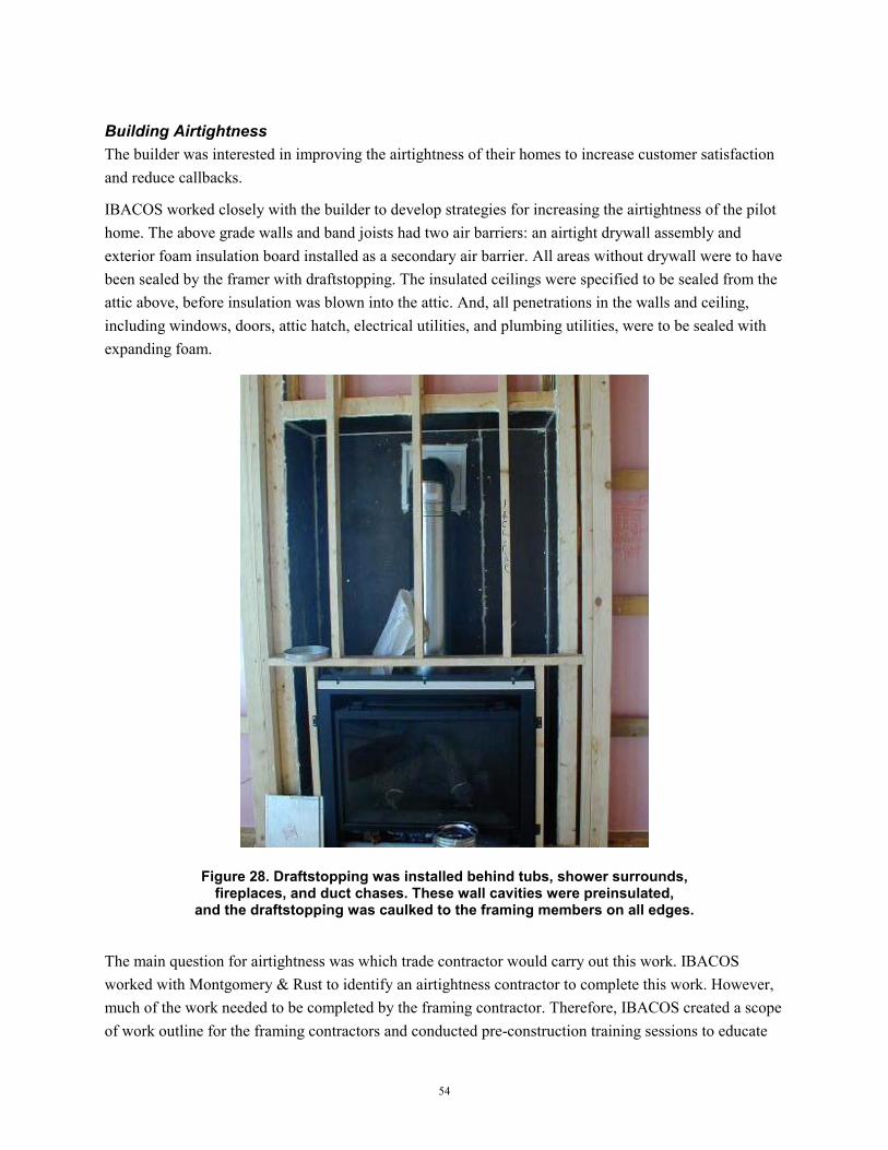
54
Building Airtightness The builder was interested in improving the airtightness of their homes to increase customer satisfaction and reduce callbacks.
IBACOS worked closely with the builder to develop strategies for increasing the airtightness of the pilot home. The above grade walls and band joists had two air barriers: an airtight drywall assembly and exterior foam insulation board installed as a secondary air barrier. All areas without drywall were to have been sealed by the framer with draftstopping. The insulated ceilings were specified to be sealed from the attic above, before insulation was blown into the attic. And, all penetrations in the walls and ceiling, including windows, doors, attic hatch, electrical utilities, and plumbing utilities, were to be sealed with expanding foam.
Figure 28. Draftstopping was installed behind tubs, shower surrounds, fireplaces, and duct chases. These wall cavities were preinsulated,
and the draftstopping was caulked to the framing members on all edges.
The main question for airtightness was which trade contractor would carry out this work. IBACOS worked with Montgomery & Rust to identify an airtightness contractor to complete this work. However, much of the work needed to be completed by the framing contractor. Therefore, IBACOS created a scope of work outline for the framing contractors and conducted pre-construction training sessions to educate

55
the framers and the site supervisors on each airtightness measure. IBACOS constructed a full-scale mock-up of a portion of the house in our Innovation Center to conduct hands-on training. IBACOS then visited the site throughout the construction process to ensure that these measures were properly implemented in the field, and that any lingering questions were answered.
Despite all this effort, the process of implementing all the airtightness measures did not proceed without some glitches. On the first home, the airtightness contractor received a different work order for the exterior walls than originally discussed, causing him to make multiple trips to the site to get everything completed in the walls. The penetration through the chimney wall for the direct-vent fireplace flue was not sealed, as both the airtightness contractor and the fireplace installer thought that the other was responsible for the work. Next, the insulation crew blew loose-fill fiberglass into the attic before the airtightness contractor had an opportunity to seal the ceiling from above. The insulation contractor thought he was doing the site supervisor a favor by taking the initiative to do the work and inadvertently threw off the construction process. In the process of building this pilot home, the builder and their various trades learned the new scopes of work for each contractor and the revised construction process for properly implementing the airtightness measures. With a clearer understanding of this process, IBACOS anticipates that the next few houses the builder and these trades build will have even better airtightness than the pilot home.
Figure 29. The foundation walls were insulated above and below grade with semirigid fiberglass board. XPS insulation board was used on all above-grade walls
and taped to improve airtightness and create a drainage plane.

56
Durability Improvements In the Village A pilot home, wall durability was enhanced through the use of flashing around windows and doors and the correct use of a drainage layer behind the exterior cladding. Flexible membrane flashing was installed at the sills of window rough openings in the home. This method protects the most vulnerable area of the window framing from potential moisture problems. The window installer became familiar with Dupont’s new Flexwrap product as a result of this work. After the sill was flashed, the window was set in place with caulk behind the side and head flange. Last, the membrane flashing was applied on each window jamb and then across the head of the window (Figure 30, Figure 31).
The extruded polystyrene insulation board on the exterior walls was used to create a secondary drainage plane behind the exterior cladding. A tongue-and-groove insulation board was used, and then all of the seams between the boards were sealed with tape. This drainage plane assembly was used behind the brick veneers and behind the fiber cement siding used on parts of the walls. Builder personnel who worked directly on the project now have a better understanding of the dynamics of moisture movement in walls and how to effectively deal with the properties of different cladding systems.
Figure 30. Dupont FlexWrap was used to flash the windows. The sill was flashed before the window was installed.

57
Figure 31. After the window was installed, FlexWrap was installed on the jambs, then across the window head.
Air Distribution and HVAC Optimization For builder personnel involved in the project and the HVAC subcontractor, the air distribution and equipment optimization strategy was a learning process. In general, the contractor learned proper protocol for sizing mechanical equipment for a high-performance home, for properly sizing the duct system to balance conditioned airflows, and for properly selecting a furnace fan to deliver the proper amount of air through the duct system. Unfortunately, the initial systems integration design that included open-web floor trusses for the first and second floor was revised by the builder to have solid 2-x-10 floor framing for the first floor. This decision saved some costs for the framing materials, but it resulted in extra steel beams in the basement that blocked the best path for the duct trunks. This complicated the duct system, increasing the number of fittings and length of duct. This, in turn, increased the total external static pressure the duct system, which meant that a larger furnace fan was needed to move the proper amount of air throughout the house. This discussion revealed to builder staff the interrelationships of the various systems in the house, especially the framing system and duct system. IBACOS has been able to convince the builder to switch back to the original design with engineered wood-floor framing for the next Village A house.
The HVAC contractor and the builder also learned about the value of using a fully ducted return system and sealing all the ductwork with mastic. As a benchmarking exercise, IBACOS conducted duct pressurization tests on some of the homes the builder constructed with the same HVAC contractor before the design work began on this pilot home. This benchmarking gave all parties involved an understanding of the performance of the current practices with respect to duct leakage. Both were present when IBACOS conducted the preliminary and final duct pressurization tests on the pilot home, and they were able to immediately see the difference in leakage compared to their standard practices. This entire process
58
has helped the builder and their HVAC contractor install higher quality systems that maintain better comfort and improve their bottom line by reducing callbacks and complaints.
Mechanical Ventilation and Indoor Air Quality Installing a mechanical ventilation system and developing an indoor air quality strategy for the home was a new effort for the builder. Almost all of the homes Montgomery and Rust has built over the years have not had mechanical ventilation systems, instead relying on natural infiltration to provide fresh air. Given that the pilot home was going to be made as airtight as possible, the builder was eager to have a mechanical ventilation system, but they did not want it to be expensive. Therefore, IBACOS developed an exhaust with passive supply ventilation system using an energy-efficient, low-sone, two-speed bath exhaust fan. The fan is intended to run continuously on low speed, exhausting about 60 cfm of air. The occupants can turn the fan up to high speed when using the bathroom, at which point the fan should move about 110 cfm of air. A 5-in. fresh air intake duct with a 50-cfm constant airflow regulator was also installed from the first-floor band joist to the return plenum. Therefore, whenever the central system is operating, the ventilation system will be balanced, and fresh air will be filtered and distributed throughout the house. When the system is operating, a controlled opening for make-up air for the exhaust fan is provided.
IBACOS had to work closely with the electrician to get the two-speed bath fan properly installed. IBACOS installed a mock-up of the system in our Innovation Center, and provided the electrician with a wiring diagram after he had difficulty replicating the system in the field. The builder was pleased with the ventilation system.
In many previous homes, the builder installed ventless gas fireplaces, as they were very popular with their homebuyers. For the pilot home, IBACOS explained to the builder the indoor air quality concerns and health issues related to ventless fireplaces. Through these discussions, the builder came to understand the importance of using direct-vent fireplaces and mechanical equipment. IBACOS also worked with the builder to ensure that the kitchen exhaust hood and all the bath fans were ducted to the outside. Through the pilot home process, the builder gained valuable experience with building houses that help maintain good indoor air quality.
Cost and Performance Considerations
This neighborhood is a unique project in that the development team has developed home performance standards that set a high level of quality for all the houses in the neighborhood. These standards are being used in marketing for the community to help distinguish this neighborhood as the best place to live in the region. This is part of a message that has caught the interest of many potential homebuyers, and the homebuilders are seeing the market appeal of high-quality housing in the context of a landmark community. The developer had to hold a lottery among the interested buyers to determine who would purchase homes in the first phase of construction. Because high-performance housing has been promised in the marketing and mandated by the developer, all of the builders are serious about delivering high-quality houses, even if construction costs are higher.

59
That said, the builder believes that the innovative technologies discussed above are costing them an additional $5,000 more than similar-sized houses they have built previously to lower performance standards. However, the high demand for these high-performance homes indicates that these increased construction costs may be helping rather than hurting the bottom line. While the construction costs are increased by $5,000, the value in the eyes of the potential buyers is increased much more than this amount, so the builder is able to increase profits.
Future Plans
The pilot home was intended to develop a workable design and set of specifications for the builder to implement on all of the houses they build in this neighborhood. Based on the mandate of the community home performance standard, the builder is committed to constructing high performance homes. The purpose of the pilot home process and the associated construction training was to accelerate the learning curve associated with implementing new and improved construction practices and to determine the optimal high performance solutions for the builder and their team of trades.
The builder is pleased with the performance of the pilot home and all of the products and construction systems recommended by IBACOS. They are already in the process of replicating these specifications on three other house plans. As they begin to replicate the improved construction process, the builder will look to make some improvements based on the knowledge gained from the pilot home. These improvements are discussed below.
• Building Airtightness Montgomery and Rust and their trades completed 90% or more of the airtightness measures on the pilot home. They now have a better understanding of the construction process for sealing the insulated ceilings from above before the attic insulation is installed. The site supervisor also has a much clearer picture of what to expect from the airtightness contractor and can do a better job of inspecting their work and ensuring that they do not miss items throughout the house. These items should improve the airtightness of the next houses enough to hit the target of 2.5 ACH at 50 Pa called for in the community's home performance standards.
• Air Distribution and Framing Integration On the next Village A home, the framing system for the first floor will be engineered framing members, most likely wood TJI (Trus Joist MacMillan Incorporated) joists. In this case, the framing for the first and second floors will span the same direction, and the duct trunks can run parallel to the steel beams in the basement. This will simplify the duct system in the basement, which in the first home had multiple supply trunks nestled between the 2 x 10 floor joists. The reduced fittings and duct length will reduce the external static pressure and result in better airflow throughout the house. This system will also greatly reduce the labor necessary to install and seal the ductwork, which should reduce total costs for the house.
The return system for the first and second floors will be sized and installed according to design to properly balance return airflows.
60
Bibliography
Internal Brochure: IBACOS, Inc. John Wieland Homes and Neighborhoods: NREL / Building America Brochure, The New American Home 2002. Pittsburgh: IBACOS, January 2002.
External Article:
IBACOS, Inc. John Wieland Homes and Neighborhoods: "Plantation Island: The New American Home 2002." BUILDER Magazine, p. 136-160, February 2002.
Presentations:
IBACOS, Inc. John Wieland Homes and Neighborhoods: Presentation given by IBACOS at the International Builder's Show in Atlanta, February 2002. IBACOS, Inc. Medallion Presentation Report - Given by IBACOS to Medallion Homes management in San Antonio, January 2002.
Internal Technical Reports:
IBACOS, Inc. John Wieland Homes and Neighborhoods; The New American Home 2002 Final Report. Pittsburgh: IBACOS, December 2001. IBACOS, Inc. Greystone Village Pilot Homes Final Report. Pittsburgh: IBACOS, December 2001. IBACOS, Inc. Farm Development Pilot Home at Dalton Farm Community Final Specifications Report. Pittsburgh: IBACOS, December 2001. IBACOS, Inc. ContraVest Properties Energy Analyses for Six House Types at the Community of Civano. Pittsburgh: IBACOS, July 2000. IBACOS, Inc. Calumet Management Site Visit Follow-up Report. Pittsburgh: IBACOS, August 2001. IBACOS, Inc. Calumet Management Unit #9 Final Test Results Report. Pittsburgh: IBACOS, October 2001. IBACOS, Inc. Calumet Pilot Homes Coffee Creek Development, Energy and Durability Specifications. Pittsburgh: IBACOS, April 2001. IBACOS, Inc. Montgomery & Rust, Inc: As-Built Specifications for Village A Pilot Home. Pittsburgh: IBACOS, July 2000.

REPORT DOCUMENTATION PAGE
Form Approved OMB NO. 0704-0188
Public reporting burden for this collection of information is estimated to average 1 hour per response, including the time for reviewing instructions, searching existing data sources, gathering and maintaining the data needed, and completing and reviewing the collection of information. Send comments regarding this burden estimate or any other aspect of this collection of information, including suggestions for reducing this burden, to Washington Headquarters Services, Directorate for Information Operations and Reports, 1215 Jefferson Davis Highway, Suite 1204, Arlington, VA 22202-4302, and to the Office of Management and Budget, Paperwork Reduction Project (0704-0188), Washington, DC 20503. 1. AGENCY USE ONLY (Leave blank)
2. REPORT DATE
March 2003
3. REPORT TYPE AND DATES COVERED
Subcontractor Report
4. TITLE AND SUBTITLE IBACOS 2001 Final Technical Report: Building-Scale Project Results
6. AUTHOR(S) IBACOS Consortium
5. FUNDING NUMBERS
KAR-8-18608-12
7. PERFORMING ORGANIZATION NAME(S) AND ADDRESS(ES)
IBACOS Consortium 2214 Liberty Ave. Pittsburgh, PA 15222
8. PERFORMING ORGANIZATION
REPORT NUMBER
9. SPONSORING/MONITORING AGENCY NAME(S) AND ADDRESS(ES)
National Renewable Energy Laboratory 1617 Cole Blvd. Golden, CO 80401-3393
10. SPONSORING/MONITORING
AGENCY REPORT NUMBER NREL/SR-550-31506
11. SUPPLEMENTARY NOTES
NREL Technical Monitor: Paul Norton 12a. DISTRIBUTION/AVAILABILITY STATEMENT
National Technical Information Service U.S. Department of Commerce 5285 Port Royal Road
Springfield, VA 22161
12b. DISTRIBUTION CODE
13. ABSTRACT (Maximum 200 words)
The focus of the IBACOS Building America Builder Program activities is working with builders to construct homes on a widespread basis that perform significantly better than their contemporary version and that advance residential building products and technologies. As part of the activities, performance goals are set for all homes in the areas of energy efficiency, indoor air quality, comfort, and durability. Integrated design, engineering, and construction-related work are conducted for each project. This work focuses on meeting the established goals through technical solutions.
15. NUMBER OF PAGES
14. SUBJECT TERMS IBACOS, Integrated Building and Construction Solutions, energy efficient housing, Building America, U.S. Department of Energy
16. PRICE CODE
17. SECURITY CLASSIFICATION
OF REPORT Unclassified
18. SECURITY CLASSIFICATION
OF THIS PAGE Unclassified
19. SECURITY CLASSIFICATION
OF ABSTRACT Unclassified
20. LIMITATION OF ABSTRACT
UL
NSN 7540-01-280-5500 Standard Form 298 (Rev. 2-89) Prescribed by ANSI Std. Z39-18 298-102