ibm ds8870 and ibm z systems synergy
TRANSCRIPT

Redpaper
Front cover
IBM DS8880 and IBM z Systems Synergy
Bert Dufrasne
Werner Bauer
Sherry Brunson
Andre Coelho
Peter Kimmel
Robert Tondini

International Technical Support Organization
IBM DS8880 and IBM z Systems Synergy
January 2017
REDP-5186-01
© Copyright International Business Machines Corporation 2015, 2017. All rights reserved.Note to U.S. Government Users Restricted Rights -- Use, duplication or disclosure restricted by GSA ADP ScheduleContract with IBM Corp.
Second Edition (January 2017)
This edition applies to IBM DS8880 firmware Release 8.2.
This document was created or updated on January 20, 2017.
Note: Before using this information and the product it supports, read the information in “Notices” on page v.
Contents
Notices . . . . . . . . . . . . . . . . . . . . . . . . . . . . . . . . . . . . . . . . . . . . . . . . . . . . . . . . . . . . . . . . . .vTrademarks . . . . . . . . . . . . . . . . . . . . . . . . . . . . . . . . . . . . . . . . . . . . . . . . . . . . . . . . . . . . . . vi
Preface . . . . . . . . . . . . . . . . . . . . . . . . . . . . . . . . . . . . . . . . . . . . . . . . . . . . . . . . . . . . . . . . . viiAuthors. . . . . . . . . . . . . . . . . . . . . . . . . . . . . . . . . . . . . . . . . . . . . . . . . . . . . . . . . . . . . . . . . . viiNow you can become a published author, too! . . . . . . . . . . . . . . . . . . . . . . . . . . . . . . . . . . viiiComments welcome. . . . . . . . . . . . . . . . . . . . . . . . . . . . . . . . . . . . . . . . . . . . . . . . . . . . . . . . ixStay connected to IBM Redbooks . . . . . . . . . . . . . . . . . . . . . . . . . . . . . . . . . . . . . . . . . . . . . ix
Chapter 1. Introduction. . . . . . . . . . . . . . . . . . . . . . . . . . . . . . . . . . . . . . . . . . . . . . . . . . . . 11.1 IBM DS8000 and z Systems synergy . . . . . . . . . . . . . . . . . . . . . . . . . . . . . . . . . . . . . . . 2
1.1.1 The z Systems server heritage . . . . . . . . . . . . . . . . . . . . . . . . . . . . . . . . . . . . . . . . 21.1.2 The disk storage system heritage . . . . . . . . . . . . . . . . . . . . . . . . . . . . . . . . . . . . . . 21.1.3 The connecting layer. . . . . . . . . . . . . . . . . . . . . . . . . . . . . . . . . . . . . . . . . . . . . . . . 21.1.4 Putting the pieces together: Synergy . . . . . . . . . . . . . . . . . . . . . . . . . . . . . . . . . . . 21.1.5 The mainframe and storage end-to-end configuration model . . . . . . . . . . . . . . . . . 3
1.2 Synergy items . . . . . . . . . . . . . . . . . . . . . . . . . . . . . . . . . . . . . . . . . . . . . . . . . . . . . . . . . 41.2.1 Disaster recovery and high availability items . . . . . . . . . . . . . . . . . . . . . . . . . . . . . 41.2.2 Data protection and backup . . . . . . . . . . . . . . . . . . . . . . . . . . . . . . . . . . . . . . . . . . 41.2.3 Management and configuration synergy items . . . . . . . . . . . . . . . . . . . . . . . . . . . . 51.2.4 DS8880 and z/OS performance synergy items. . . . . . . . . . . . . . . . . . . . . . . . . . . . 5
Chapter 2. Disaster recovery and high availability . . . . . . . . . . . . . . . . . . . . . . . . . . . . . 72.1 DS8000 Copy Services functions . . . . . . . . . . . . . . . . . . . . . . . . . . . . . . . . . . . . . . . . . . 8
2.1.1 Metro Mirror 2-site synchronous volume replication . . . . . . . . . . . . . . . . . . . . . . . . 82.1.2 Global Mirror 2-site asynchronous volume replication . . . . . . . . . . . . . . . . . . . . . . 92.1.3 zGlobal Mirror 2-site asynchronous volume replication . . . . . . . . . . . . . . . . . . . . 102.1.4 Metro/Global Mirror (MGM) 3-site solution . . . . . . . . . . . . . . . . . . . . . . . . . . . . . . 122.1.5 Multiple Target PPRC 3-site solutions . . . . . . . . . . . . . . . . . . . . . . . . . . . . . . . . . 14
2.2 z/OS HyperSwap. . . . . . . . . . . . . . . . . . . . . . . . . . . . . . . . . . . . . . . . . . . . . . . . . . . . . . 172.3 Copy Services Manager and HyperSwap . . . . . . . . . . . . . . . . . . . . . . . . . . . . . . . . . . . 18
2.3.1 HyperSwap to site H2 . . . . . . . . . . . . . . . . . . . . . . . . . . . . . . . . . . . . . . . . . . . . . . 212.3.2 Return to site H1 . . . . . . . . . . . . . . . . . . . . . . . . . . . . . . . . . . . . . . . . . . . . . . . . . . 212.3.3 Summary. . . . . . . . . . . . . . . . . . . . . . . . . . . . . . . . . . . . . . . . . . . . . . . . . . . . . . . . 23
2.4 Geographically Dispersed Parallel Sysplex (GDPS) . . . . . . . . . . . . . . . . . . . . . . . . . . . 232.4.1 GDPS and DS8000 synergy features . . . . . . . . . . . . . . . . . . . . . . . . . . . . . . . . . . 242.4.2 GDPS and DS8000 synergy summary . . . . . . . . . . . . . . . . . . . . . . . . . . . . . . . . . 28
Chapter 3. Data protection and backup . . . . . . . . . . . . . . . . . . . . . . . . . . . . . . . . . . . . . 293.1 Fast replication backup . . . . . . . . . . . . . . . . . . . . . . . . . . . . . . . . . . . . . . . . . . . . . . . . . 30
3.1.1 SMS construct copy pool to support FRBACKUP as input . . . . . . . . . . . . . . . . . . 303.1.2 Copy pool backup storage group for output to FRBACKUP . . . . . . . . . . . . . . . . . 313.1.3 Combining copy pool and copy pool backup storage group . . . . . . . . . . . . . . . . . 333.1.4 FRBACKUP brings it all together . . . . . . . . . . . . . . . . . . . . . . . . . . . . . . . . . . . . . 333.1.5 FRBACKUP software-based interaction . . . . . . . . . . . . . . . . . . . . . . . . . . . . . . . . 35
3.2 Using FlashCopy with DB2 and IMS . . . . . . . . . . . . . . . . . . . . . . . . . . . . . . . . . . . . . . . 363.2.1 FlashCopy and DB2 for z/OS synergy . . . . . . . . . . . . . . . . . . . . . . . . . . . . . . . . . 363.2.2 FlashCopy and IMS for z/OS synergy. . . . . . . . . . . . . . . . . . . . . . . . . . . . . . . . . . 38
© Copyright IBM Corp. 2015, 2017. All rights reserved. iii
Chapter 4. Management and configuration . . . . . . . . . . . . . . . . . . . . . . . . . . . . . . . . . . 414.1 Storage pool design considerations . . . . . . . . . . . . . . . . . . . . . . . . . . . . . . . . . . . . . . . 42
4.1.1 Storage pool design considerations within z/OS. . . . . . . . . . . . . . . . . . . . . . . . . . 424.1.2 DS8000 storage pools . . . . . . . . . . . . . . . . . . . . . . . . . . . . . . . . . . . . . . . . . . . . . 454.1.3 Combining SMS storage groups and DS8000 extent pools . . . . . . . . . . . . . . . . . 46
4.2 Extended address volume (EAV) V2. . . . . . . . . . . . . . . . . . . . . . . . . . . . . . . . . . . . . . . 474.2.1 Data set type dependencies on an EAV R2 . . . . . . . . . . . . . . . . . . . . . . . . . . . . . 484.2.2 z/OS prerequisites for EAV volumes. . . . . . . . . . . . . . . . . . . . . . . . . . . . . . . . . . . 494.2.3 How to identify an EAV 2 . . . . . . . . . . . . . . . . . . . . . . . . . . . . . . . . . . . . . . . . . . . 504.2.4 EAV R2 migration considerations . . . . . . . . . . . . . . . . . . . . . . . . . . . . . . . . . . . . . 50
4.3 Dynamic volume expansion (DVE) . . . . . . . . . . . . . . . . . . . . . . . . . . . . . . . . . . . . . . . . 514.4 Quick initialization . . . . . . . . . . . . . . . . . . . . . . . . . . . . . . . . . . . . . . . . . . . . . . . . . . . . . 524.5 Volume formatting overwrite protection. . . . . . . . . . . . . . . . . . . . . . . . . . . . . . . . . . . . . 534.6 Channel paths and control-unit-initiated reconfiguration. . . . . . . . . . . . . . . . . . . . . . . . 554.7 CKD thin provisioning . . . . . . . . . . . . . . . . . . . . . . . . . . . . . . . . . . . . . . . . . . . . . . . . . . 554.8 DSCLI on z/OS . . . . . . . . . . . . . . . . . . . . . . . . . . . . . . . . . . . . . . . . . . . . . . . . . . . . . . . 57
Chapter 5. IBM z Systems and DS8880 performance . . . . . . . . . . . . . . . . . . . . . . . . . . 595.1 Parallel access volume (PAV), HyperPAV, and SuperPAV . . . . . . . . . . . . . . . . . . . . . 60
5.1.1 Dynamic PAV tuning with z/OS Workload Manager . . . . . . . . . . . . . . . . . . . . . . . 625.1.2 HyperPAV . . . . . . . . . . . . . . . . . . . . . . . . . . . . . . . . . . . . . . . . . . . . . . . . . . . . . . . 635.1.3 Resource Measurement Facility (RMF) reporting on PAV . . . . . . . . . . . . . . . . . . 655.1.4 PAV and HyperPAV in z/VM environments. . . . . . . . . . . . . . . . . . . . . . . . . . . . . . 665.1.5 SuperPAV . . . . . . . . . . . . . . . . . . . . . . . . . . . . . . . . . . . . . . . . . . . . . . . . . . . . . . . 67
5.2 Multiple allegiance. . . . . . . . . . . . . . . . . . . . . . . . . . . . . . . . . . . . . . . . . . . . . . . . . . . . . 705.3 I/O priority queuing . . . . . . . . . . . . . . . . . . . . . . . . . . . . . . . . . . . . . . . . . . . . . . . . . . . . 715.4 Modified Indirect Data Access Word (MIDAW) . . . . . . . . . . . . . . . . . . . . . . . . . . . . . . . 725.5 Caching algorithm optimized for z Systems . . . . . . . . . . . . . . . . . . . . . . . . . . . . . . . . . 735.6 z High Performance FICON for IBM z Systems (zHPF) . . . . . . . . . . . . . . . . . . . . . . . . 75
5.6.1 DB2 enhancements with zHPF . . . . . . . . . . . . . . . . . . . . . . . . . . . . . . . . . . . . . . . 775.6.2 Extended distance and extended distance II . . . . . . . . . . . . . . . . . . . . . . . . . . . . 785.6.3 Enhanced FICON Information Unit (IU) pacing. . . . . . . . . . . . . . . . . . . . . . . . . . . 79
5.7 Easy Tier . . . . . . . . . . . . . . . . . . . . . . . . . . . . . . . . . . . . . . . . . . . . . . . . . . . . . . . . . . . . 805.7.1 Easy Tier Application . . . . . . . . . . . . . . . . . . . . . . . . . . . . . . . . . . . . . . . . . . . . . . 805.7.2 Heat map transfer (HMT) . . . . . . . . . . . . . . . . . . . . . . . . . . . . . . . . . . . . . . . . . . . 82
5.8 I/O Priority Manager and WLM for z/OS integration . . . . . . . . . . . . . . . . . . . . . . . . . . . 835.9 zHyperWrite . . . . . . . . . . . . . . . . . . . . . . . . . . . . . . . . . . . . . . . . . . . . . . . . . . . . . . . . . 85
5.9.1 zHyperWrite installation and enablement . . . . . . . . . . . . . . . . . . . . . . . . . . . . . . . 875.10 DS8000 Copy Services performance considerations . . . . . . . . . . . . . . . . . . . . . . . . . 885.11 DS8000 and z13 and z13s I/O enhancements . . . . . . . . . . . . . . . . . . . . . . . . . . . . . . 90
5.11.1 FICON Dynamic Routing (FIDR). . . . . . . . . . . . . . . . . . . . . . . . . . . . . . . . . . . . . 915.11.2 Forward Error Correction (FER) . . . . . . . . . . . . . . . . . . . . . . . . . . . . . . . . . . . . . 935.11.3 Read Diagnostic Parameters (RDP) for improved fault isolation . . . . . . . . . . . . 945.11.4 SAN Fabric I/O Priority management . . . . . . . . . . . . . . . . . . . . . . . . . . . . . . . . . 96
5.12 zEnterprise Data Compression (zEDC). . . . . . . . . . . . . . . . . . . . . . . . . . . . . . . . . . . . 98
Related publications . . . . . . . . . . . . . . . . . . . . . . . . . . . . . . . . . . . . . . . . . . . . . . . . . . . . . 99IBM Redbooks . . . . . . . . . . . . . . . . . . . . . . . . . . . . . . . . . . . . . . . . . . . . . . . . . . . . . . . . . . . 99Other publications . . . . . . . . . . . . . . . . . . . . . . . . . . . . . . . . . . . . . . . . . . . . . . . . . . . . . . . 100Online resources . . . . . . . . . . . . . . . . . . . . . . . . . . . . . . . . . . . . . . . . . . . . . . . . . . . . . . . . 100Help from IBM . . . . . . . . . . . . . . . . . . . . . . . . . . . . . . . . . . . . . . . . . . . . . . . . . . . . . . . . . . 100
iv IBM DS8880 and IBM z Systems Synergy
Notices
This information was developed for products and services offered in the US. This material might be available from IBM in other languages. However, you may be required to own a copy of the product or product version in that language in order to access it.
IBM may not offer the products, services, or features discussed in this document in other countries. Consult your local IBM representative for information on the products and services currently available in your area. Any reference to an IBM product, program, or service is not intended to state or imply that only that IBM product, program, or service may be used. Any functionally equivalent product, program, or service that does not infringe any IBM intellectual property right may be used instead. However, it is the user’s responsibility to evaluate and verify the operation of any non-IBM product, program, or service.
IBM may have patents or pending patent applications covering subject matter described in this document. The furnishing of this document does not grant you any license to these patents. You can send license inquiries, in writing, to:IBM Director of Licensing, IBM Corporation, North Castle Drive, MD-NC119, Armonk, NY 10504-1785, US
INTERNATIONAL BUSINESS MACHINES CORPORATION PROVIDES THIS PUBLICATION “AS IS” WITHOUT WARRANTY OF ANY KIND, EITHER EXPRESS OR IMPLIED, INCLUDING, BUT NOT LIMITED TO, THE IMPLIED WARRANTIES OF NON-INFRINGEMENT, MERCHANTABILITY OR FITNESS FOR A PARTICULAR PURPOSE. Some jurisdictions do not allow disclaimer of express or implied warranties in certain transactions, therefore, this statement may not apply to you.
This information could include technical inaccuracies or typographical errors. Changes are periodically made to the information herein; these changes will be incorporated in new editions of the publication. IBM may make improvements and/or changes in the product(s) and/or the program(s) described in this publication at any time without notice.
Any references in this information to non-IBM websites are provided for convenience only and do not in any manner serve as an endorsement of those websites. The materials at those websites are not part of the materials for this IBM product and use of those websites is at your own risk.
IBM may use or distribute any of the information you provide in any way it believes appropriate without incurring any obligation to you.
The performance data and client examples cited are presented for illustrative purposes only. Actual performance results may vary depending on specific configurations and operating conditions.
Information concerning non-IBM products was obtained from the suppliers of those products, their published announcements or other publicly available sources. IBM has not tested those products and cannot confirm the accuracy of performance, compatibility or any other claims related to non-IBM products. Questions on the capabilities of non-IBM products should be addressed to the suppliers of those products.
Statements regarding IBM’s future direction or intent are subject to change or withdrawal without notice, and represent goals and objectives only.
This information contains examples of data and reports used in daily business operations. To illustrate them as completely as possible, the examples include the names of individuals, companies, brands, and products. All of these names are fictitious and any similarity to actual people or business enterprises is entirely coincidental.
COPYRIGHT LICENSE:
This information contains sample application programs in source language, which illustrate programming techniques on various operating platforms. You may copy, modify, and distribute these sample programs in any form without payment to IBM, for the purposes of developing, using, marketing or distributing application programs conforming to the application programming interface for the operating platform for which the sample programs are written. These examples have not been thoroughly tested under all conditions. IBM, therefore, cannot guarantee or imply reliability, serviceability, or function of these programs. The sample programs are provided “AS IS”, without warranty of any kind. IBM shall not be liable for any damages arising out of your use of the sample programs.
© Copyright IBM Corp. 2015, 2017. All rights reserved. v
Trademarks
IBM, the IBM logo, and ibm.com are trademarks or registered trademarks of International Business Machines Corporation, registered in many jurisdictions worldwide. Other product and service names might be trademarks of IBM or other companies. A current list of IBM trademarks is available on the web at “Copyright and trademark information” at http://www.ibm.com/legal/copytrade.shtml
The following terms are trademarks or registered trademarks of International Business Machines Corporation, and might also be trademarks or registered trademarks in other countries.
AIX®CICS®DB2®DS8000®Easy Tier®ECKD™Enterprise Storage Server®FICON®FlashCopy®GDPS®Geographically Dispersed Parallel
Sysplex™HyperSwap®
IBM®IBM z Systems®IBM z13®IBM zHyperWrite™IMS™Parallel Sysplex®POWER8®Redbooks®Redpaper™Redbooks (logo) ®Resource Measurement Facility™RMF™S/390®
System Storage®Tivoli®z Systems®z/Architecture®z/OS®z/VM®z/VSE®z10™z13™z13s™z9®zEnterprise®
The following terms are trademarks of other companies:
Linux is a trademark of Linus Torvalds in the United States, other countries, or both.
Windows, and the Windows logo are trademarks of Microsoft Corporation in the United States, other countries, or both.
UNIX is a registered trademark of The Open Group in the United States and other countries.
Other company, product, or service names may be trademarks or service marks of others.
vi IBM DS8880 and IBM z Systems Synergy
Preface
From inception, what is known today as IBM® z Systems® always had a close and unique relation to its storage. Over the years, improvements to the z Systems processors and storage software, the disk storage systems and their communication architecture have constantly reinforced the synergy.
This IBM Redpaper™ publication summarizes and highlights the various aspects, advanced functions, and technologies that are often pioneered by IBM, and that make the IBM z Systems and the IBM DS8880 an ideal combination.
This paper is intended for those who have some familiarity with z Systems and the IBM DS8000® series and want a condensed but comprehensive overview of the synergy items up to the IBM z13® and z13s™, and the IBM DS8880 Release 8.2 firmware.
Authors
This paper was produced by a team of specialists from around the world working at the International Technical Support Organization (ITSO), San Jose Center.
Bert Dufrasne is an IBM Certified IT Specialist and Project Leader for IBM System Storage® disk products at the ITSO, San Jose Center. He has worked at IBM in various IT areas. He has written many IBM Redbooks® publications and has developed and taught technical workshops. Before joining the ITSO, he worked for IBM Global Services as an Application Architect. He holds a Master’s degree in Electrical Engineering.
Werner Bauer is a Certified Consulting IT Specialist in Germany. He has more than 30 years of experience in storage software and hardware, and with IBM S/390® and IBM z/OS®. His areas of expertise include disaster recovery (DR) solutions based on IBM enterprise disk storage systems. Werner is a frequent speaker at storage conferences and GUIDE SHARE EUROPE (GSE) meetings. He has also written extensively for various Redbooks publications about the DS8000. He holds a degree in Economics from the University of Heidelberg, and in Mechanical Engineering from FH Heilbronn. He currently works with System Vertrieb Alexander (SVA), an IBM Premier Business Partner.
Sherry Brunson joined IBM in March 1985 and worked as a Large System Customer Engineer before becoming a Top Gun in 1990. Sherry is a Top Gun in Eastern US for all storage products, POWER Systems, and z Systems. She has supported and implemented DS8000 and scaled out network appliance storage products globally and also developed and taught educational classes. She also has taught z Systems classes in the US.
Andre Coelho is a Consulting IT Storage Specialist in Rio de Janeiro, Brazil. He works for Internal Accounts (US and EMEA). He has over 30 years of experience in z/OS and predecessor operating systems. His areas of expertise include among others, DFSMS, DFSMShsm, and DFSMSrmm, DS8000, and Hydra. He has contributed to several Redbooks publications.
© Copyright IBM Corp. 2015, 2017. All rights reserved. vii
Peter Kimmel is an IT Specialist and ATS team lead with the Enterprise Storage Solutions team at the EMEA Storage Competence Center (ESCC) in Kelsterbach, Germany. He joined IBM Storage in 1999 and since then has worked with all the various IBM Enterprise Storage Server® (ESS) and System Storage DS8000 generations, with a focus on architecture and performance. He was involved in the Early Shipment Programs (ESPs) of these early installations, and co-authored several DS8000 Redbooks publications. Peter holds a Diploma (MSc) degree in Physics from the University of Kaiserslautern.
Robert Tondini is a Certified Senior IT Specialist based in IBM Australia, providing storage technical support. He has 20 years of experience in the mainframe and storage environments. His areas of expertise include IBM high-end disk and tape storage subsystems and disaster recovery solutions. He co-authored several Redbooks publications and workshops for IBM enterprise storage systems, Advanced Copy Services, and IBM Tivoli® Storage Productivity Center for Replication.
Thanks to the following people for their contributions to this project:
Nick Clayton, Scott Compton, Craig Gordon, Roger Hathorn, Hank Sautter, Brian Sherman, Paul Spagnolo, Warren Stanley, Alexander Warmuth, Teena Werley, Sonny Williams, Harry YudenfriendIBM
Alan Hicks, Howard Johnson, Brian StefflerBrocade
Now you can become a published author, too!
Here’s an opportunity to spotlight your skills, grow your career, and become a published author—all at the same time! Join an ITSO residency project and help write a book in your area of expertise, while honing your experience using leading-edge technologies. Your efforts will help to increase product acceptance and customer satisfaction, as you expand your network of technical contacts and relationships. Residencies run from two to six weeks in length, and you can participate either in person or as a remote resident working from your home base.
Find out more about the residency program, browse the residency index, and apply online at:
ibm.com/redbooks/residencies.html
viii IBM DS8880 and IBM z Systems Synergy
Comments welcome
Your comments are important to us!
We want our papers to be as helpful as possible. Send us your comments about this paper or other IBM Redbooks publications in one of the following ways:
� Use the online Contact us review Redbooks form found at:
ibm.com/redbooks
� Send your comments in an email to:
� Mail your comments to:
IBM Corporation, International Technical Support OrganizationDept. HYTD Mail Station P0992455 South RoadPoughkeepsie, NY 12601-5400
Stay connected to IBM Redbooks
� Find us on Facebook:
http://www.facebook.com/IBMRedbooks
� Follow us on Twitter:
http://twitter.com/ibmredbooks
� Look for us on LinkedIn:
http://www.linkedin.com/groups?home=&gid=2130806
� Explore new Redbooks publications, residencies, and workshops with the IBM Redbooks weekly newsletter:
https://www.redbooks.ibm.com/Redbooks.nsf/subscribe?OpenForm
� Stay current on recent Redbooks publications with RSS Feeds:
http://www.redbooks.ibm.com/rss.html
Preface ix

x IBM DS8880 and IBM z Systems Synergy
Chapter 1. Introduction
This chapter provides background information about the topics covered in this paper and that make the IBM DS8880 and IBM z Systems® servers an ideal combination.
Although most of the synergy items discussed here apply when combining the DS8880 with a comprehensive z/OS software level, some apply also to other operating systems that use IBM z Systems, including zLinux, z/TPF, z/VM®, and z/VSE®.
This chapter includes the following topics:
� IBM DS8000 and z Systems synergy� Synergy items
1
© Copyright IBM Corp. 2015, 2017. All rights reserved. 1
1.1 IBM DS8000 and z Systems synergy
This section presents some historical background to show that the strong ties between the IBM DS8000 and z Systems go back to their origins.
1.1.1 The z Systems server heritage
IBM owns the architecture of z Systems hardware and fundamental software, such as IBM z/OS, z/VM, z/Linux, z/TPF, or z/VSE with their components and subsystems such as I/O Supervisor, Channel Subsystem, and access methods to data on connected disk storage systems.
Since the advent of mainframe servers in 1964 with the IBM System/360 server family, this server architecture is continuously enhanced and developed to provide the most reliable application server on the market while still maintaining operational efficiency. IBM z Systems today can reach any level of scalability needed to run the most demanding workloads.
1.1.2 The disk storage system heritage
With disk storage servers IBM also has a rich history and extensive experience. IBM created the first randomly accessed disk storage system in 1956, and also pioneered many technological breakthrough achievements. IBM invented, developed, and built more advanced disk storage servers culminating today with the most advanced disk storage server, the IBM DS8000 storage systems, and its flagship, the DS8880 model.
1.1.3 The connecting layer
The piece that brings these products together and has them interact in an optimal fashion is finally a connection technology that IBM also invented and continuously enhances and improves through the years.
The technology’s first appearance was in 1990 when IBM presented a newly created serial I/O protocol between z Systems servers and storage systems, ESCON. It was implemented to run through optical fiber technology to replace the aged copper-based bus and tag channel interface technology, and overcome performance and distance limitations imposed by these parallel channels.
In 1998, this serial I/O interface technology was eventually enhanced to IBM FICON® technology, using full duplex Fibre Channel and multiplexing capabilities. FICON is the IBM interpretation of Fibre Channel technology that IBM enhanced for z Systems optimal connection performance, reliability and security.
1.1.4 Putting the pieces together: Synergy
Because IBM owns all of these building blocks and their respective architectures, integrating these components to get the best overall efficiency from the complete solution is easier. This is what we call synergy and is based on the fact that each component understands the potential of other components and can make the best use of it. Integrating the DS8880, z Systems, and communication components results in a combination that offers more than just the sum of its individual components.
2 IBM DS8880 and IBM z Systems Synergy
1.1.5 The mainframe and storage end-to-end configuration model
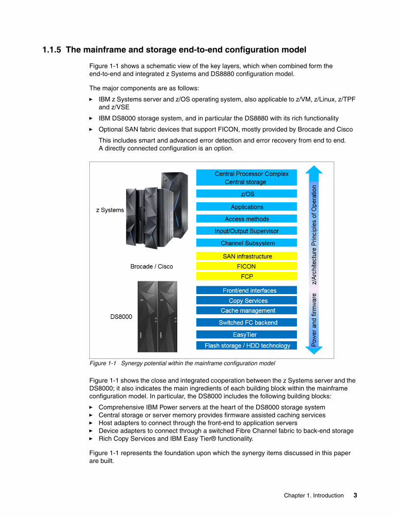
Figure 1-1 shows a schematic view of the key layers, which when combined form the end-to-end and integrated z Systems and DS8880 configuration model.
The major components are as follows:
� IBM z Systems server and z/OS operating system, also applicable to z/VM, z/Linux, z/TPF and z/VSE
� IBM DS8000 storage system, and in particular the DS8880 with its rich functionality
� Optional SAN fabric devices that support FICON, mostly provided by Brocade and Cisco
This includes smart and advanced error detection and error recovery from end to end.A directly connected configuration is an option.
Figure 1-1 Synergy potential within the mainframe configuration model
Figure 1-1 shows the close and integrated cooperation between the z Systems server and the DS8000; it also indicates the main ingredients of each building block within the mainframe configuration model. In particular, the DS8000 includes the following building blocks:
� Comprehensive IBM Power servers at the heart of the DS8000 storage system� Central storage or server memory provides firmware assisted caching services� Host adapters to connect through the front-end to application servers� Device adapters to connect through a switched Fibre Channel fabric to back-end storage� Rich Copy Services and IBM Easy Tier® functionality.
Figure 1-1 represents the foundation upon which the synergy items discussed in this paper are built.
Chapter 1. Introduction 3
1.2 Synergy items
This paper highlights the most important and popular synergy items of z Systems server and DS8000 disk storage server.
1.2.1 Disaster recovery and high availability items
Chapter 2, “Disaster recovery and high availability” on page 7 has details of the Copy Services functions that the DS8000 provides, which are as follows:
� IBM FlashCopy® with all its options
FlashCopy is a popular function and is the foundation for solutions such as the IBM DB2® BACKUP SYSTEM utility and other exploiters. BACKUP SYSTEM is closely interconnected in z/OS with DFSMS software constructs such as Copy Pools and Copy Pool Backup Storage Groups.
� Global Copy
This is used to asynchronously replicating volumes without guaranteeing consistent data at the target site.
� Global Mirror
This is used to asynchronously replicating volumes while guaranteeing consistent data at the target site, by combining Global Copy and FlashCopy.
� Metro Mirror
This is another popular function to synchronously replicate data from a source volume to a target volume and is usually managed through Tivoli Storage Productivity Center for Replication or the IBM Geographically Dispersed Parallel Sysplex™ (IBM GDPS®).
� z Global Mirror (zGM)
This is another 2-site disaster recovery solution and is formerly known as Extended Remote Copy (XRC). zGM still requires proper firmware support in the primary or source storage system but relies mainly on its software based component which is the System Data Mover within z/OS.
� 3-site solutions
These include cascaded Metro/Global Mirror (MGM) and Multiple Target Peer-to-Peer Remote Copy (MT-PPRC), which provide two copies based on a single source volume. These copies can be either both synchronously replicated copies or asynchronously replicated copies or a mixture of both, synchronous and asynchronous replications.
� Another 3-site multi-target volume replication relationship consists of a Metro Mirror relationship and a zGM replication relationship from the same primary or source volume.
1.2.2 Data protection and backup
Chapter 3, “Data protection and backup” on page 29 covers the software-based interface to FlashCopy.
This support is integrated into system-managed storage within z/OS and can be exploited by any other utility or application also.
An exploiter of this software-based support is the BACKUP SYSTEM DB2 utility. Its availability started with z/OS 1.8 and was significantly enhanced in subsequent versions, for example to include FlashCopy Consistency Groups support.
4 IBM DS8880 and IBM z Systems Synergy
1.2.3 Management and configuration synergy items
Chapter 4, “Management and configuration” on page 41 explains how z/OS storage software integrates with DS8000 extent pools and has considerations for defining storage pools based on what is needed from an application perspective.
That chapters also explains the integration between z/OS storage software and DS8000 volume management, and more explicitly discusses these items:
� Extended addressing volumes (EAV)
EAV provides support for z/OS large volumes allowing to reduce the total number of volumes within a Parallel Sysplex configuration.
� Quick Initialization (Quick Init)
This allows for any new volume that is created within the DS8000 to be used almost immediately by the host without having to wait until the full internal initialization process is complete.
� Dynamic volume expansion (DVE)
This is another synergy item that is possible through collaboration between storage software and DS8000. With DVE, the size of existing volumes within a DS8000 can dynamically be increased as needed.
� DS8000 Query Host Access function
This is exploited by IBM Device Support Facility (ICKDSF) and GDPS and is used to protect volumes from accidental formatting and data-overwriting.
� CKD Thin Provisioning
Starting with Release 8.1.1. of the DS8880 microcode, CKD volumes can be created as extent space-efficient (ESE) volumes and can use small extents (21 cylinders).
1.2.4 DS8880 and z/OS performance synergy items
Chapter 5, “IBM z Systems and DS8880 performance” on page 59 describes the rich performance functions of z/OS and DS8000 that efficiently complement each other. See these sections:
� 5.1, “Parallel access volume (PAV), HyperPAV, and SuperPAV” on page 60
The IBM Enterprise Storage Server, a predecessor of the DS8000 Series, already supported the Parallel Access Volumes feature, in concert with z/OS. HyperPAV and SuperPAV are consequent enhancements within the DS8000 and supported today at the z/OS system software level.
� 5.2, “Multiple allegiance” on page 70
Multiple allegiance is another capability, also initially introduced with the Enterprise Storage Server and enhanced with the DS8000.
� 5.3, “I/O priority queuing” on page 71
I/O priority queuing allows I/O from separate z/OS system images to be queued and therefore handled in a priority order.
� 5.4, “Modified Indirect Data Access Word (MIDAW)” on page 72
MIDAW is a modification to IBM z/Architecture® channel programming providing a method to gather data from and to scatter data to non-contiguous storage locations during an I/O operation. This capability has a positive effect on FICON channel performance. The DFSMS Media Manager, a z/OS I/O driver that is logically located between the access
Chapter 1. Introduction 5
method and the Input/Output Supervisor (IOS) during the execution of an I/O operation, uses MIDAWs. Its use has grown over time, specifically in z/DB2 environments.
� 5.5, “Caching algorithm optimized for z Systems” on page 73
DS8000 cache management is another important piece in providing outstanding performance when reading or writing data to the storage system. In an autonomic fashion, the DS8000 firmware chooses the most appropriate caching algorithm, in an adaptive manner, to handle host data as fast and efficiently as possible.
� 5.6, “z High Performance FICON for IBM z Systems (zHPF)” on page 75
The z Systems High Performance FICON (zHPF) within the z Systems architecture is another significant enhancement, particular to the z Systems Channel Subsystem and its I/O drivers. zHPF represents a significant change in how to execute channel programs and reduce the I/O management overhead within the z Systems server, on the channel itself. zHPF benefits from the enhanced host adapter capabilities in the DS8000.
� 5.7, “Easy Tier” on page 80
Easy Tier is another significant improvement for the DS8000. IBM Easy Tier allows the DS8000 to automatically and adequately place the data on the proper back-end storage tier, and can also balance workload within a tier.
� 5.8, “I/O Priority Manager and WLM for z/OS integration” on page 83
The z Systems Workload Manager (zWLM), in conjunction with the DS8000 Priority Manager is another example of how z Systems can cooperate with the DS8000. This cooperation leads to end-to-end managed priority of z/OS based workloads.
� 5.9, “zHyperWrite” on page 85
A particular enhancement is zHyperWrite, which allows the I/O driver to schedule up to three parallel write I/Os and direct one or two of these writes to Metro Mirror (MM) target volumes to avoid the potential synchronous replication overhead of Metro Mirror.
� 5.10, “DS8000 Copy Services performance considerations” on page 88
See why understanding the potential impact to an application write I/O is important when this I/O is replicated. We distinguish between Copy Services provided by the DS8000, thus mainly controlled by the DS8000 firmware, and the z/OS software-based replication solution, z Global Mirror (zGM, formerly known as Extended Remote Copy, XRC). zGM still requires respective support in the primary storage system.
� 5.11, “DS8000 and z13 and z13s I/O enhancements” on page 90
With z Systems server z13, z13s and later, and DS8880 or DS8870 with firmware releases 7.5 and later, a series of SAN fabric-related enhancements are introduced. These enhancements relate to the 16 Gbps SAN port technology including the z13 FICON channels. Also new functions are built-in to accommodate the higher speed and address a higher potential of transmitting errors through Forward Error Correction and also Fibre Channel Read Diagnostic Parameters. FICON Dynamic Routing will use dynamic routing capabilities in the fabric, provided by the SAN fabric vendors.
� 5.12, “zEnterprise Data Compression (zEDC)” on page 98
Another synergy component we can pinpoint is the IBM zEnterprise® Data Compression (zEDC) capability and the hardware adapter called zEDC Express that can be used with z/OS V2.1 and later.
6 IBM DS8880 and IBM z Systems Synergy
Chapter 2. Disaster recovery and high availability
This chapter describes the various data and volume replication techniques that are implemented in the DS8000 as Copy Services, and which provide the foundations for disaster recovery operations and enable high data availability. The DS8000 Copy Services are complemented by management frameworks and functions built directly into the z Systems software and firmware. This functional complementarity allows a further enhanced automation approach that can handle almost any potential incident, even in an unattended environment composed of z Systems servers and DS8000 storage systems.
This chapter includes the following topics:
� DS8000 Copy Services functions� z/OS HyperSwap� Copy Services Manager and HyperSwap� Geographically Dispersed Parallel Sysplex (GDPS)
2
© Copyright IBM Corp. 2015, 2017. All rights reserved. 7
2.1 DS8000 Copy Services functions
The DS8000 provides broad and rich Copy Services functions. They can be used for 2-site or 3-site solutions. Although not discussed in this paper, another possibility is to combine these Copy Services capabilities and expanding to 4-site configurations, if required.
2.1.1 Metro Mirror 2-site synchronous volume replication
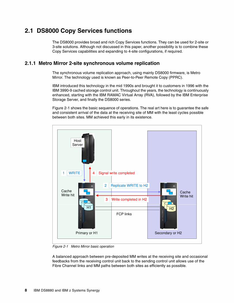
The synchronous volume replication approach, using mainly DS8000 firmware, is Metro Mirror. The technology used is known as Peer-to-Peer Remote Copy (PPRC).
IBM introduced this technology in the mid 1990s and brought it to customers in 1996 with the IBM 3990-9 cached storage control unit. Throughout the years, the technology is continuously enhanced, starting with the IBM RAMAC Virtual Array (RVA), followed by the IBM Enterprise Storage Server, and finally the DS8000 series.
Figure 2-1 shows the basic sequence of operations. The real art here is to guarantee the safe and consistent arrival of the data at the receiving site of MM with the least cycles possible between both sites. MM achieved this early in its existence.
Figure 2-1 Metro Mirror basic operation
A balanced approach between pre-deposited MM writes at the receiving site and occasional feedbacks from the receiving control unit back to the sending control unit allows use of the Fibre Channel links and MM paths between both sites as efficiently as possible.
HostServer
WRITE
Replicate WRITE to H2
Signal write completed
Cache Write hit
Cache Write hit
Write completed in H2
1
2
3
4
FCP links
H1 H2
Primary or H1 Secondary or H2
8 IBM DS8880 and IBM z Systems Synergy
2.1.2 Global Mirror 2-site asynchronous volume replication
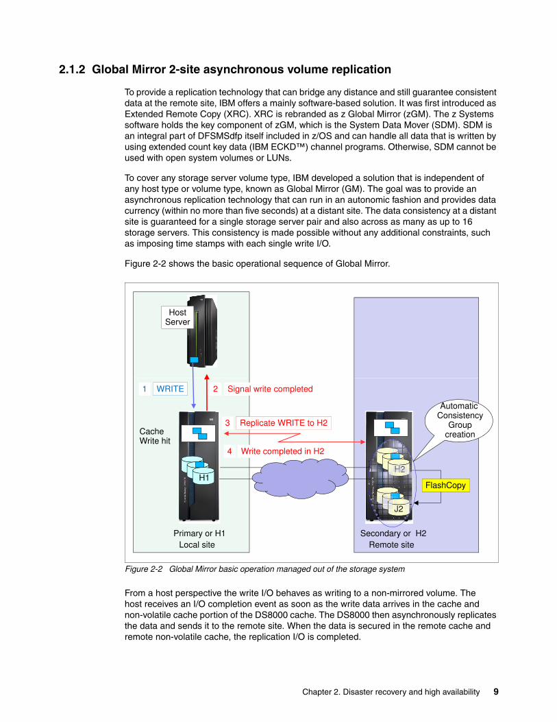
To provide a replication technology that can bridge any distance and still guarantee consistent data at the remote site, IBM offers a mainly software-based solution. It was first introduced as Extended Remote Copy (XRC). XRC is rebranded as z Global Mirror (zGM). The z Systems software holds the key component of zGM, which is the System Data Mover (SDM). SDM is an integral part of DFSMSdfp itself included in z/OS and can handle all data that is written by using extended count key data (IBM ECKD™) channel programs. Otherwise, SDM cannot be used with open system volumes or LUNs.
To cover any storage server volume type, IBM developed a solution that is independent of any host type or volume type, known as Global Mirror (GM). The goal was to provide an asynchronous replication technology that can run in an autonomic fashion and provides data currency (within no more than five seconds) at a distant site. The data consistency at a distant site is guaranteed for a single storage server pair and also across as many as up to 16 storage servers. This consistency is made possible without any additional constraints, such as imposing time stamps with each single write I/O.
Figure 2-2 shows the basic operational sequence of Global Mirror.
Figure 2-2 Global Mirror basic operation managed out of the storage system
From a host perspective the write I/O behaves as writing to a non-mirrored volume. The host receives an I/O completion event as soon as the write data arrives in the cache and non-volatile cache portion of the DS8000 cache. The DS8000 then asynchronously replicates the data and sends it to the remote site. When the data is secured in the remote cache and remote non-volatile cache, the replication I/O is completed.
HostServer
H2
WRITE
Replicate WRITE to H2
Signal write completed1
3
2
Cache Write hit
Automatic Consistency
Groupcreation
Write completed in H24
H1H2
Local site Remote site
J2
FlashCopy
Primary or H1 Secondary or H2
Chapter 2. Disaster recovery and high availability 9
Global Mirror combines the Global Copy and FlashCopy functions: Global Copy performs the data replication and FlashCopy secures the previous data from H2 onto J2 before the respective track on H2 is overwritten by the replication I/O. So, J2 behaves like a journal for H2.
GM and its consistency group creation process is solely performed within the DS8000 storage servers. Synergy comes into play when managing such a configuration through Copy Services Manager or the Geographically Dispersed Parallel Sysplex (GDPS).
2.1.3 zGlobal Mirror 2-site asynchronous volume replication
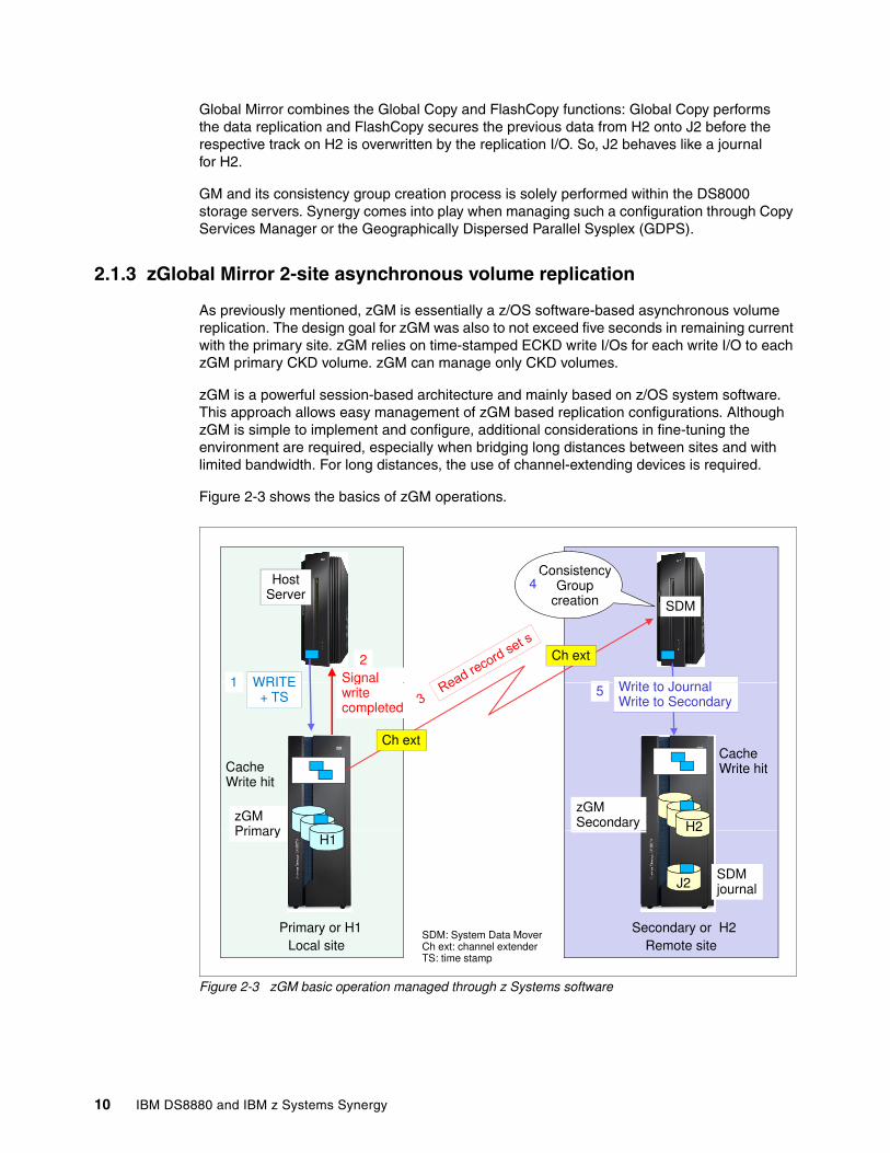
As previously mentioned, zGM is essentially a z/OS software-based asynchronous volume replication. The design goal for zGM was also to not exceed five seconds in remaining current with the primary site. zGM relies on time-stamped ECKD write I/Os for each write I/O to each zGM primary CKD volume. zGM can manage only CKD volumes.
zGM is a powerful session-based architecture and mainly based on z/OS system software. This approach allows easy management of zGM based replication configurations. Although zGM is simple to implement and configure, additional considerations in fine-tuning the environment are required, especially when bridging long distances between sites and with limited bandwidth. For long distances, the use of channel-extending devices is required.
Figure 2-3 shows the basics of zGM operations.
Figure 2-3 zGM basic operation managed through z Systems software
HostServer
Signal WRITE1
2
ConsistencyGroup
creation4
SDM
W it t J l
Ch ext
H2
gwrite completed
WRITE+ TS
1
Cache Write hit
zGMPrimary
zGMSecondary
Cache Write hit
Write to JournalWrite to Secondary
5
Ch ext
H1H2
Local site Remote site
SDMjournal
Primary or H1 Secondary or H2
Primary
J2
SDM: System Data MoverCh ext: channel extenderTS: time stamp
10 IBM DS8880 and IBM z Systems Synergy
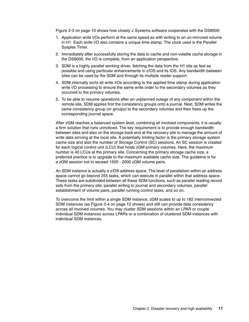
Figure 2-3 on page 10 shows how closely z Systems software cooperates with the DS8000:
1. Application write I/Os perform at the same speed as with writing to an un-mirrored volume in H1. Each write I/O also contains a unique time stamp. The clock used is the Parallel Sysplex Timer.
2. Immediately after successfully storing the data to cache and non-volatile cache storage in the DS8000, the I/O is complete, from an application perspective.
3. SDM is a highly parallel working driver, fetching the data from the H1 site as fast as possible and using particular enhancements in z/OS and its IOS. Any bandwidth between sites can be used by the SDM and through its multiple reader support.
4. SDM internally sorts all write I/Os according to the applied time stamp during application write I/O processing to ensure the same write order to the secondary volumes as they occurred to the primary volumes.
5. To be able to resume operations after an unplanned outage of any component within the remote site, SDM applies first the consistency groups onto a journal. Next, SDM writes the same consistency group (or groups) to the secondary volumes and then frees up the corresponding journal space.
After zGM reaches a balanced system level, combining all involved components, it is usually a firm solution that runs unnoticed. The key requirement is to provide enough bandwidth between sites and also on the storage back end at the recovery site to manage the amount of write data arriving at the local site. A potentially limiting factor is the primary storage system cache size and also the number of Storage Control (SC) sessions. An SC session is created for each logical control unit (LCU) that holds zGM primary volumes. Here, the maximum number is 40 LCUs at the primary site. Concerning the primary storage cache size, a preferred practice is to upgrade to the maximum available cache size. The guideline is for a zGM session not to exceed 1500 - 2000 zGM volume pairs.
An SDM instance is actually a z/OS address space. The level of parallelism within an address space cannot go beyond 255 tasks, which can execute in parallel within that address space. These tasks are subdivided between all these SDM functions, such as parallel reading record sets from the primary site, parallel writing to journal and secondary volumes, parallel establishment of volume pairs, parallel running control tasks, and so on.
To overcome the limit within a single SDM instance, zGM scales to up to 182 interconnected SDM instances (as Figure 2-4 on page 12 shows) and still can provide data consistency across all involved volumes. You may cluster SDM sessions within an LPAR or couple individual SDM instances across LPARs or a combination of clustered SDM instances with individual SDM instances.
Chapter 2. Disaster recovery and high availability 11
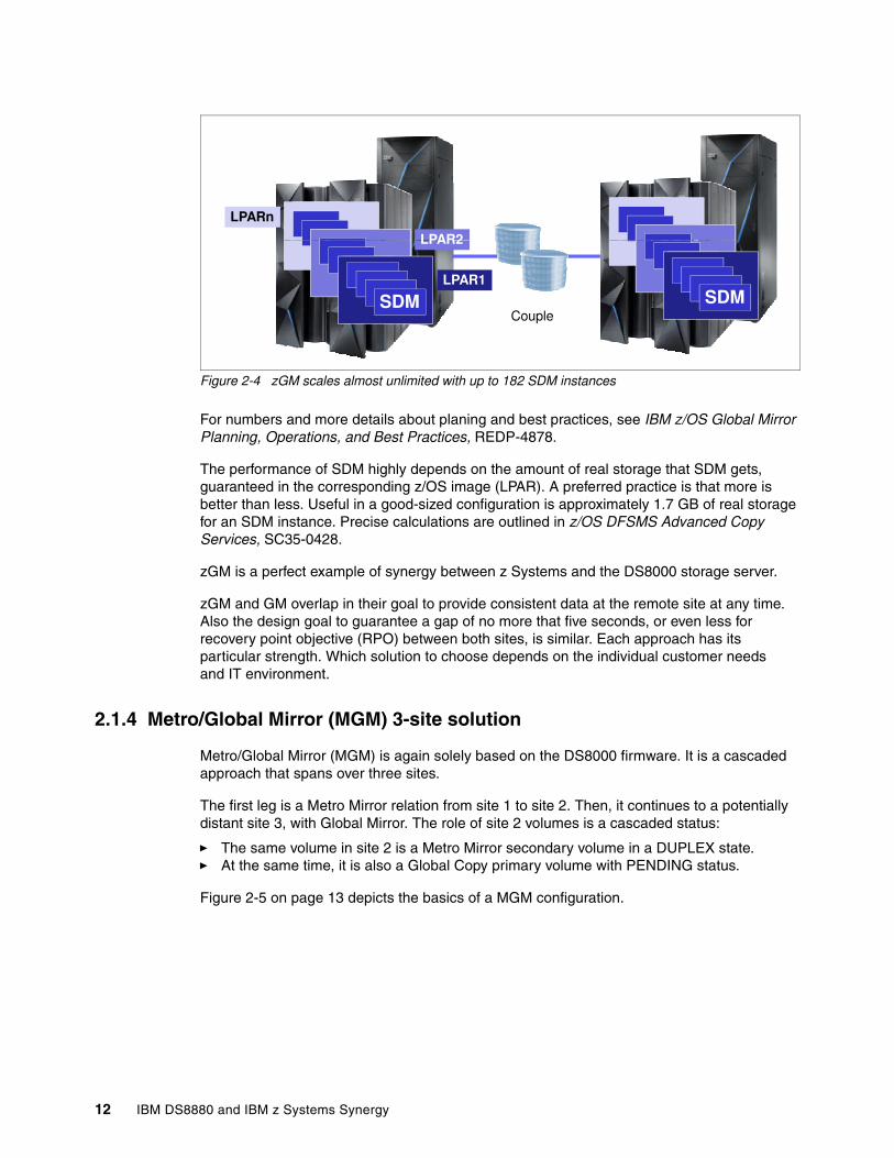
Figure 2-4 zGM scales almost unlimited with up to 182 SDM instances
For numbers and more details about planing and best practices, see IBM z/OS Global Mirror Planning, Operations, and Best Practices, REDP-4878.
The performance of SDM highly depends on the amount of real storage that SDM gets, guaranteed in the corresponding z/OS image (LPAR). A preferred practice is that more is better than less. Useful in a good-sized configuration is approximately 1.7 GB of real storage for an SDM instance. Precise calculations are outlined in z/OS DFSMS Advanced Copy Services, SC35-0428.
zGM is a perfect example of synergy between z Systems and the DS8000 storage server.
zGM and GM overlap in their goal to provide consistent data at the remote site at any time. Also the design goal to guarantee a gap of no more that five seconds, or even less for recovery point objective (RPO) between both sites, is similar. Each approach has its particular strength. Which solution to choose depends on the individual customer needs and IT environment.
2.1.4 Metro/Global Mirror (MGM) 3-site solution
Metro/Global Mirror (MGM) is again solely based on the DS8000 firmware. It is a cascaded approach that spans over three sites.
The first leg is a Metro Mirror relation from site 1 to site 2. Then, it continues to a potentially distant site 3, with Global Mirror. The role of site 2 volumes is a cascaded status:
� The same volume in site 2 is a Metro Mirror secondary volume in a DUPLEX state.� At the same time, it is also a Global Copy primary volume with PENDING status.
Figure 2-5 on page 13 depicts the basics of a MGM configuration.
LPARn
LPAR2
SDMSDM
SDMSDMSDM
SDMSDMSDM LPAR2
LPAR1
SDMSDMSDM
SDM
SDMSDMSDM
SDMCouple
12 IBM DS8880 and IBM z Systems Synergy
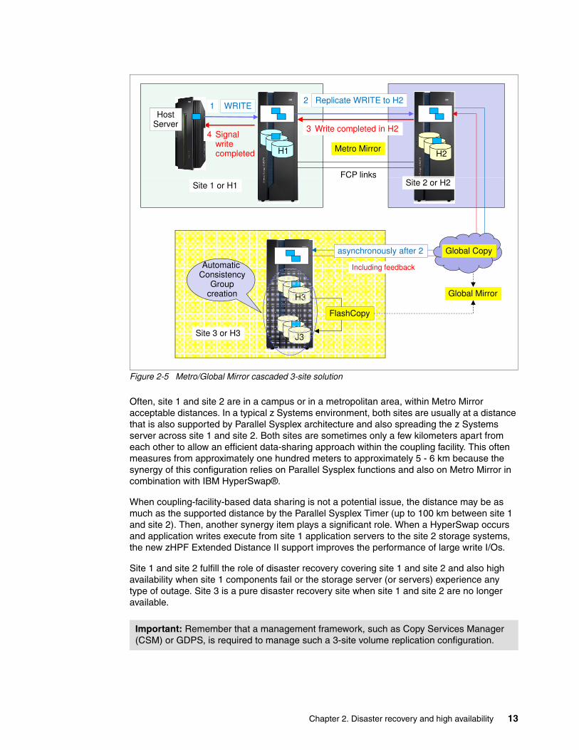
Figure 2-5 Metro/Global Mirror cascaded 3-site solution
Often, site 1 and site 2 are in a campus or in a metropolitan area, within Metro Mirror acceptable distances. In a typical z Systems environment, both sites are usually at a distance that is also supported by Parallel Sysplex architecture and also spreading the z Systems server across site 1 and site 2. Both sites are sometimes only a few kilometers apart from each other to allow an efficient data-sharing approach within the coupling facility. This often measures from approximately one hundred meters to approximately 5 - 6 km because the synergy of this configuration relies on Parallel Sysplex functions and also on Metro Mirror in combination with IBM HyperSwap®.
When coupling-facility-based data sharing is not a potential issue, the distance may be as much as the supported distance by the Parallel Sysplex Timer (up to 100 km between site 1 and site 2). Then, another synergy item plays a significant role. When a HyperSwap occurs and application writes execute from site 1 application servers to the site 2 storage systems, the new zHPF Extended Distance II support improves the performance of large write I/Os.
Site 1 and site 2 fulfill the role of disaster recovery covering site 1 and site 2 and also high availability when site 1 components fail or the storage server (or servers) experience any type of outage. Site 3 is a pure disaster recovery site when site 1 and site 2 are no longer available.
Important: Remember that a management framework, such as Copy Services Manager (CSM) or GDPS, is required to manage such a 3-site volume replication configuration.
WRITE1Host
Server
H1 H2
2
FCP links
3Signal write completed
4
Metro Mirror
Replicate WRITE to H2
Write completed in H2
Automatic C i
FCP linksSite 1 or H1
Global Copyasynchronously after 2
Including feedback
Site 2 or H2
H3
J3
FlashCopy
ConsistencyGroup
creation
Site 3 or H3
Global Mirror
g
Chapter 2. Disaster recovery and high availability 13
2.1.5 Multiple Target PPRC 3-site solutions
Multiple Target PPRC (MT-PPRC) is available with DS8880 or DS8870 configurations with firmware levels 7.4 or later. It is also a 3-site Copy Services configuration.
It is called Multiple-Target PPRC, reusing again the term PPRC, because it can have two Copy Services based volume copies in site 2 and another in site 3. These Copy Services relationships can be either of two approaches:
� Two Metro Mirror relationships of the same site 1 volume � A combination of a Metro Mirror relationship between site 1 and site 2 and a second
Global Mirror or Global Copy relationship from site 1 to another site 3
Both approaches are described.
MT-PPRC can be used to migrate data from primary or secondary DS8000 storage systems in PPRC configuration. The use of MT-PPRC allows for a migration procedure with either little or no periods of time where the system is not protected by mirroring.
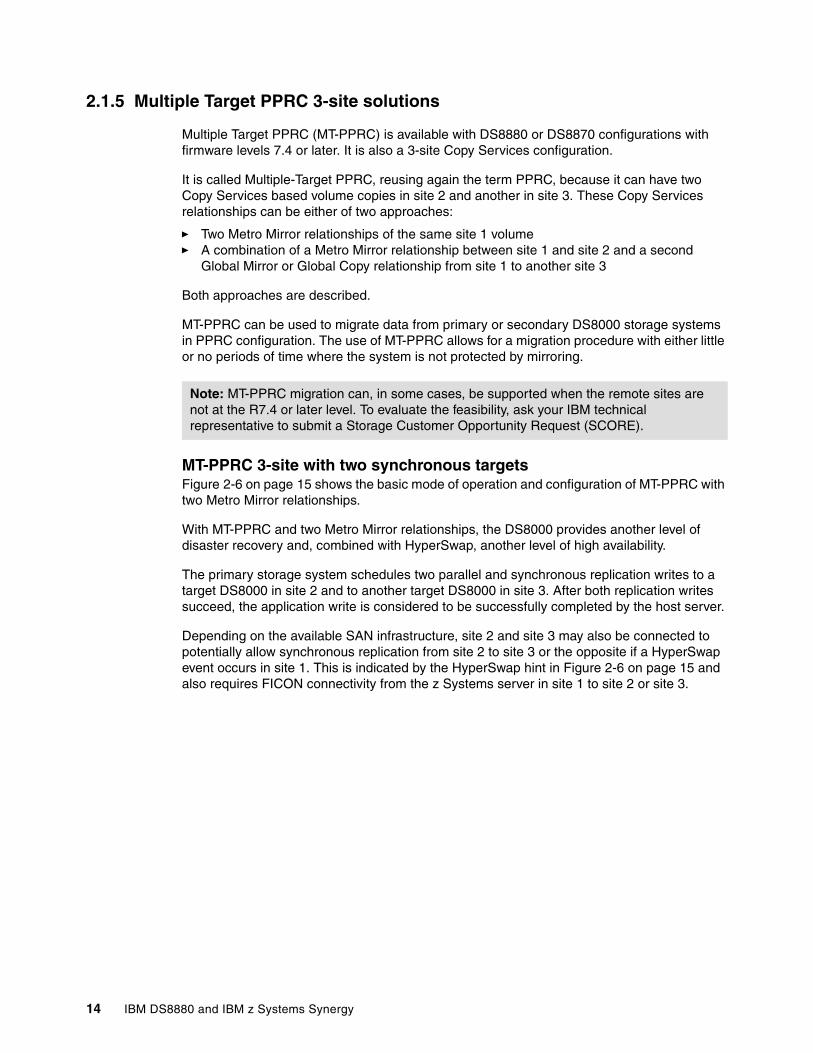
MT-PPRC 3-site with two synchronous targetsFigure 2-6 on page 15 shows the basic mode of operation and configuration of MT-PPRC with two Metro Mirror relationships.
With MT-PPRC and two Metro Mirror relationships, the DS8000 provides another level of disaster recovery and, combined with HyperSwap, another level of high availability.
The primary storage system schedules two parallel and synchronous replication writes to a target DS8000 in site 2 and to another target DS8000 in site 3. After both replication writes succeed, the application write is considered to be successfully completed by the host server.
Depending on the available SAN infrastructure, site 2 and site 3 may also be connected to potentially allow synchronous replication from site 2 to site 3 or the opposite if a HyperSwap event occurs in site 1. This is indicated by the HyperSwap hint in Figure 2-6 on page 15 and also requires FICON connectivity from the z Systems server in site 1 to site 2 or site 3.
Note: MT-PPRC migration can, in some cases, be supported when the remote sites are not at the R7.4 or later level. To evaluate the feasibility, ask your IBM technical representative to submit a Storage Customer Opportunity Request (SCORE).
14 IBM DS8880 and IBM z Systems Synergy
Figure 2-6 Multiple Target PPRC with two synchronous targets
Managing such a 3-site MT-PPRC configuration is supported by GDPS (GDPS/MTMM), or by Copy Services Manager. This is also proof of how closely z Systems based Copy Services software and HyperSwap interact with the connected DS8000 storage servers.
MT-PPRC 3-site with synchronous and asynchronous targetFigure 2-7 on page 16, which shows another possible MT-PPRC configuration, implies a Parallel Sysplex configuration across site 1 and site 2.
Storage system in site 1 synchronously replicates disk storage volumes over Metro Mirror to site 2.
Although the SAN fabric configuration in Figure 2-7 on page 16 also allows a cascaded configuration from site 2 to site 3, the implication here is that Global Mirror is the second Copy Services relationship from site 1 to site 3 and running through a SAN fabric, which might have SAN switches in all three sites. This configuration allows for the highest flexibility.
HostServer
Signal H2
Cache Write hit
4
2
Replicate WRITE to H22Replicate WRITE to H32
Metro Mirror
HyperSwap
WRITE
gwrite completed
Cache Write hit
Site 2 or H21
3
Cache 23
Metro Mirror
Metro Mirror
FCP links
H1
Site 1 or H1 3 Write completed in H3
H3
Site 3 or H3
Write hit
FCP links
3 Write completed in H2
Chapter 2. Disaster recovery and high availability 15
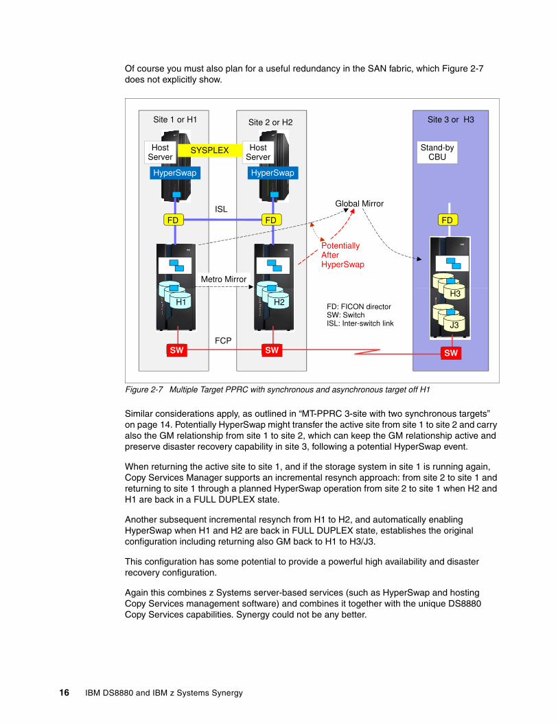
Of course you must also plan for a useful redundancy in the SAN fabric, which Figure 2-7 does not explicitly show.
Figure 2-7 Multiple Target PPRC with synchronous and asynchronous target off H1
Similar considerations apply, as outlined in “MT-PPRC 3-site with two synchronous targets” on page 14. Potentially HyperSwap might transfer the active site from site 1 to site 2 and carry also the GM relationship from site 1 to site 2, which can keep the GM relationship active and preserve disaster recovery capability in site 3, following a potential HyperSwap event.
When returning the active site to site 1, and if the storage system in site 1 is running again, Copy Services Manager supports an incremental resynch approach: from site 2 to site 1 and returning to site 1 through a planned HyperSwap operation from site 2 to site 1 when H2 and H1 are back in a FULL DUPLEX state.
Another subsequent incremental resynch from H1 to H2, and automatically enabling HyperSwap when H1 and H2 are back in FULL DUPLEX state, establishes the original configuration including returning also GM back to H1 to H3/J3.
This configuration has some potential to provide a powerful high availability and disaster recovery configuration.
Again this combines z Systems server-based services (such as HyperSwap and hosting Copy Services management software) and combines it together with the unique DS8880 Copy Services capabilities. Synergy could not be any better.
Site 1 or H1
HostServer
Site 3 or H3Site 2 or H2
HostServer
Stand-byCBU
SYSPLEX
HyperSwap HyperSwap
FD FD FDISL
Metro Mirror
Global Mirror
PotentiallyAfterHyperSwap
H1H3
H2
J3
SW SW SWFCP
FD: FICON directorSW: SwitchISL: Inter-switch link
16 IBM DS8880 and IBM z Systems Synergy
2.2 z/OS HyperSwap
For many years, z/OS has provided the capability to transparently swap the access from one device to another device. First exploitations for disk storage volumes happened with PPRC dynamic address switching (P/DAS). Through system commands such as IOACTION and SWAP, transparently switching I/O from a primary Metro Mirror volume to a secondary Metro Mirror volume is possible. This capability was implemented in the last editions of IBM 3990-6 and IBM RVA disk storage control units.
For details, see these IBM Knowledge Center pages:
� http://www.ibm.com/support/knowledgecenter/SSLTBW_2.2.0/com.ibm.zos.v2r2.antg000/pdas.htm
� http://www.ibm.com/support/knowledgecenter/en/SSLTBW_2.2.0/com.ibm.zos.v2r2.antg000/gr392.htm
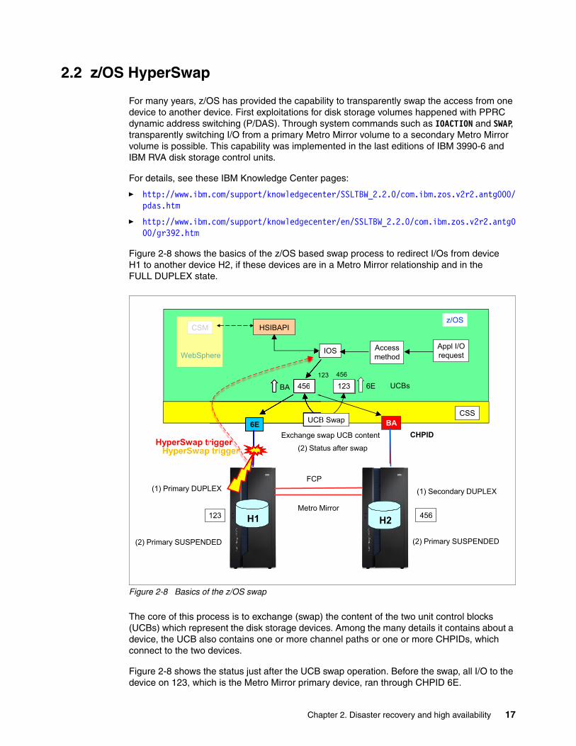
Figure 2-8 shows the basics of the z/OS based swap process to redirect I/Os from device H1 to another device H2, if these devices are in a Metro Mirror relationship and in the FULL DUPLEX state.
Figure 2-8 Basics of the z/OS swap
The core of this process is to exchange (swap) the content of the two unit control blocks (UCBs) which represent the disk storage devices. Among the many details it contains about a device, the UCB also contains one or more channel paths or one or more CHPIDs, which connect to the two devices.
Figure 2-8 shows the status just after the UCB swap operation. Before the swap, all I/O to the device on 123, which is the Metro Mirror primary device, ran through CHPID 6E.
HSIBAPIz/OS
WebSphere
CSM
Appl I/O
requestAccess
methodIOS
CSS
BA6E
123 456
123 456456 123
(2) Primary SUSPENDED
UCB Swap
H1
FCP
H2
(1) Secondary DUPLEX(1) Primary DUPLEX
UCBs
(2) Primary SUSPENDED
BA 6E
Exchange swap UCB content
(2) Status after swap
Metro Mirror
CHPIDHyperSwap trigger
ere
6E
456
UCB
BA
Exchange sw
(2) Statriggerr
123 456
Chapter 2. Disaster recovery and high availability 17
Eventually all I/O traffic to 123 is stopped before the actual swap operation occurs. After all I/O to 123 is quiesced, the swap process exchanges the UCB content of device 123 and device 456. After the swap is completed, IOS resumes I/O operations, and the UCB eventually directs the resumed I/O to CHPID BA, which connects to device 456. A prior step of the swap process is also to change the Metro Mirror status of the device on 456 from SECONDARY DUPLEX to PRIMARY SUSPENDED state.
IBM enhanced this swap process and also raised the number of swap operations executing in parallel. With today’s processor speed, and creating dedicated highly parallel executing swap services within the HyperSwap address space, many thousands of swap operations can occur in single digit number of seconds. Highly cultivating this swap process to today’s standard is now called HyperSwap and performs in its own address space.
In addition to the actual swap operation that today’s z/OS HyperSwap service provides, certain DS8000 Copy Services commands can be issued during the swap operation to trigger freeze and failover functions within the DS8000.
Also, HyperSwap operation IOS perfectly understands HyperSwap triggers to autonomically perform a HyperSwap operation after such a trigger is raised, based on an issue to or within the primary storage server in H1.
Because this HyperSwap service is not an externalized interface, another authorized user must enable this service and exercise a close cooperation with this z/OS based HyperSwap service.
Currently, authorized users of HyperSwap services are Copy Services Manager, and GDPS. Both solutions manage Copy Services configuration and now closely interact with the HyperSwap address space to provide the Copy Services configuration to HyperSwap services after the configuration is an proper FULL DUPLEX state. Another convincing example of the z Systems and DS8000 synergy.
2.3 Copy Services Manager and HyperSwap
Copy Services Manager, formerly known as Tivoli Storage Productivity Center for Replication (TPC-R), is required to use HyperSwap within z/OS for a Metro Mirror configuration. This section does not describe the Copy Services Manager beyond the fact that it manages sessions. Such a session contains all Metro Mirror volume pairs that are set up and defined within a Parallel Sysplex configuration. From a user perspective, the entity of management is just the session.
Copy Services Manager is server-based and includes two interfaces: graphical user interface (GUI) and a command-line interface (CLI). The Copy Services Manager server is usually preinstalled on the DS8880 HMC, or it can run on all common server platforms like IBM AIX®, Linux, Microsoft Windows, and on z/OS within the UNIX System Services or UNIX System Services shell.
Copy Services Manager can handle all z/OS based CKD volumes within its Metro Mirror session, even when the Copy Services Manager server is hosted on the HMC, or a distributed server. However, a good practice is to take advantage of the robust z Systems server platform and place the Copy Services Manager server in a z/OS LPAR. Furthermore, when possible, you can also host the Copy Services Manager stand-by server in another z/OS LPAR at the other site.
18 IBM DS8880 and IBM z Systems Synergy
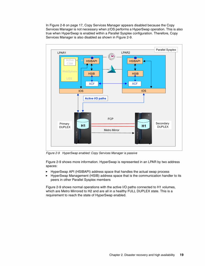
In Figure 2-8 on page 17, Copy Services Manager appears disabled because the Copy Services Manager is not necessary when z/OS performs a HyperSwap operation. This is also true when HyperSwap is enabled within a Parallel Sysplex configuration. Therefore, Copy Services Manager is also disabled as shown in Figure 2-9.
Figure 2-9 HyperSwap enabled: Copy Services Manager is passive
Figure 2-9 shows more information. HyperSwap is represented in an LPAR by two address spaces:
� HyperSwap API (HSIBAPI) address space that handles the actual swap process� HyperSwap Management (HSIB) address space that is the communication handler to its
peers in other Parallel Sysplex members
Figure 2-9 shows normal operations with the active I/O paths connected to H1 volumes, which are Metro Mirrored to H2 and are all in a healthy FULL DUPLEX state. This is a requirement to reach the state of HyperSwap enabled.
HSIB
HSIBAPI
HSIB
HSIBAPI
LPAR1 LPAR2
WebSphere
IOS
XCFXCF
IOS
Parallel Sysplex
XCF
Active
CSM
USS
Acitve I/O paths
Primary
DUPLEX
Secondary
DUPLEXH1
FCP
Metro Mirror
H1
Chapter 2. Disaster recovery and high availability 19
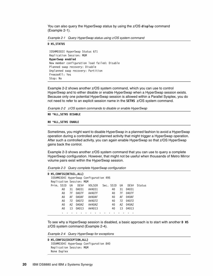
You can also query the HyperSwap status by using the z/OS display command (Example 2-1).
Example 2-1 Query HyperSwap status using z/OS system command
D HS,STATUS
IOSHM0303I HyperSwap Status 671 Replication Session: MGM HyperSwap enabled New member configuration load failed: Disable Planned swap recovery: Disable Unplanned swap recovery: Partition FreezeAll: Yes Stop: No
Example 2-2 shows another z/OS system command, which you can use to control HyperSwap and to either disable or enable HyperSwap when a HyperSwap session exists. Because only one potential HyperSwap session is allowed within a Parallel Sysplex, you do not need to refer to an explicit session name in the SETHS z/OS system command.
Example 2-2 z/OS system commands to disable or enable HyperSwap
RO *ALL,SETHS DISABLE
RO *ALL,SETHS ENABLE
Sometimes, you might want to disable HyperSwap in a planned fashion to avoid a HyperSwap operation during a controlled and planned activity that might trigger a HyperSwap operation. After such a controlled activity, you can again enable HyperSwap so that z/OS HyperSwap gains back the control.
Example 2-3 shows another z/OS system command that you can use to query a complete HyperSwap configuration. However, that might not be useful when thousands of Metro Mirror volume pairs exist within the HyperSwap session.
Example 2-3 Query complete HyperSwap configuration
D HS,CONFIG(DETAIL,ALL) IOSHM0304I HyperSwap Configuration 495 Replication Session: MGM Prim. SSID UA DEV# VOLSER Sec. SSID UA DEV# Status A0 31 0A031 A#A031 40 31 04031 A0 7F 0A07F A#A07F 40 7F 0407F A0 AF 0A0AF A#A0AF 40 AF 040AF A0 72 0A072 A#A072 40 72 04072 A0 A2 0A0A2 A#A0A2 40 A2 040A2 A0 13 0A013 A#A013 40 13 04013 . . . . . . . . . . . . . . . .
To see why a HyperSwap session is disabled, a basic approach is to start with another D HS z/OS system command (Example 2-4).
Example 2-4 Query HyperSwap for exceptions
D HS,CONFIG(EXCEPTION,ALL) IOSHM0304I HyperSwap Configuration 840 Replication Session: MGM None Duplex
20 IBM DS8880 and IBM z Systems Synergy
2.3.1 HyperSwap to site H2
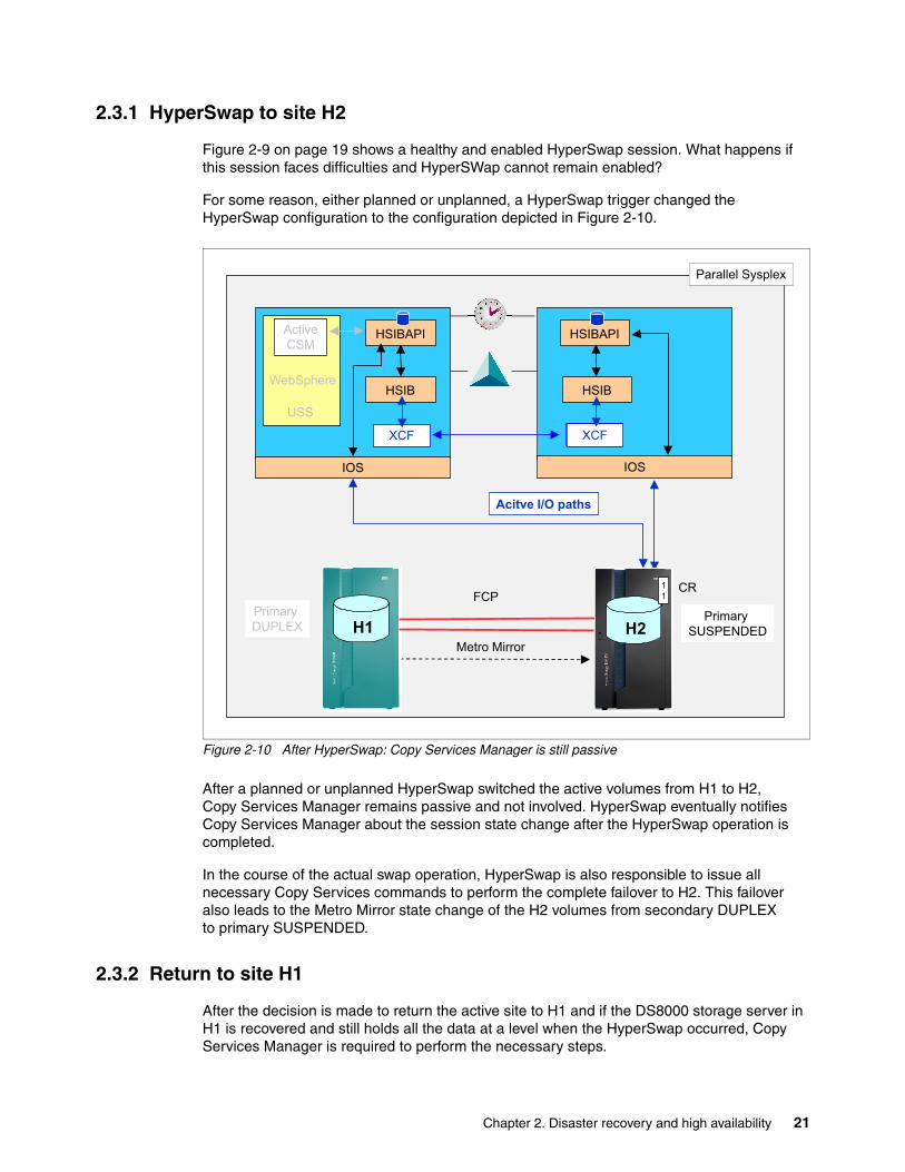
Figure 2-9 on page 19 shows a healthy and enabled HyperSwap session. What happens if this session faces difficulties and HyperSWap cannot remain enabled?
For some reason, either planned or unplanned, a HyperSwap trigger changed the HyperSwap configuration to the configuration depicted in Figure 2-10.
Figure 2-10 After HyperSwap: Copy Services Manager is still passive
After a planned or unplanned HyperSwap switched the active volumes from H1 to H2, Copy Services Manager remains passive and not involved. HyperSwap eventually notifies Copy Services Manager about the session state change after the HyperSwap operation is completed.
In the course of the actual swap operation, HyperSwap is also responsible to issue all necessary Copy Services commands to perform the complete failover to H2. This failover also leads to the Metro Mirror state change of the H2 volumes from secondary DUPLEX to primary SUSPENDED.
2.3.2 Return to site H1
After the decision is made to return the active site to H1 and if the DS8000 storage server in H1 is recovered and still holds all the data at a level when the HyperSwap occurred, Copy Services Manager is required to perform the necessary steps.
HSIB
HSIBAPI
HSIB
HSIBAPI
WebSphere
IOS
XCFXCF
IOS
Parallel Sysplex
XCF
Active
CSM
USS
Acitve I/O paths
Primary
SUSPENDED
Primary
DUPLEX H1
FCP
Metro Mirror
H2
CR1
1
Chapter 2. Disaster recovery and high availability 21
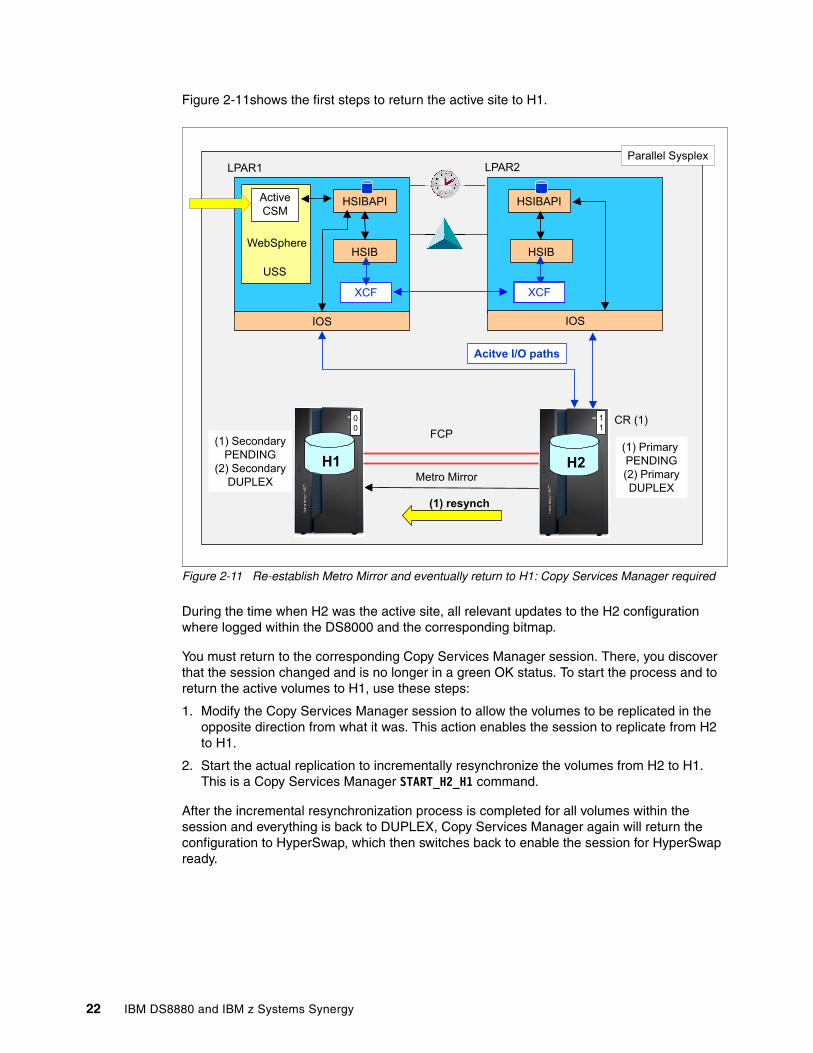
Figure 2-11shows the first steps to return the active site to H1.
Figure 2-11 Re-establish Metro Mirror and eventually return to H1: Copy Services Manager required
During the time when H2 was the active site, all relevant updates to the H2 configuration where logged within the DS8000 and the corresponding bitmap.
You must return to the corresponding Copy Services Manager session. There, you discover that the session changed and is no longer in a green OK status. To start the process and to return the active volumes to H1, use these steps:
1. Modify the Copy Services Manager session to allow the volumes to be replicated in the opposite direction from what it was. This action enables the session to replicate from H2 to H1.
2. Start the actual replication to incrementally resynchronize the volumes from H2 to H1. This is a Copy Services Manager START_H2_H1 command.
After the incremental resynchronization process is completed for all volumes within the session and everything is back to DUPLEX, Copy Services Manager again will return the configuration to HyperSwap, which then switches back to enable the session for HyperSwap ready.
HSIB
HSIBAPI
HSIB
HSIBAPI
WebSphere
IOS
XCFXCF
IOS
Parallel Sysplex
XCF
Active
CSM
USS
Acitve I/O paths
(1) Primary
PENDING
(2) Primary
DUPLEX
(1) Secondary
PENDING
(2) Secondary
DUPLEX
H1
FCP
Metro Mirror
H2
(1) resynch
LPAR1 LPAR2
CR (1)1
10
0
22 IBM DS8880 and IBM z Systems Synergy
To finally return the active volumes back to H1 is another two-step process:
1. Issue a planned HyperSwap, either through the Copy Services Manager or through the SETHS SWAP z/OS system command. This command again performs a swap operation and puts the active volumes back to H1, including the Metro Mirror status of primary SUSPENDED.
2. Copy Services Manager does the same double action as before:
a. Allows the session to replicate from H1to H2.
b. Resynchronizes all the volume pairs from H1to H2 through another START_H1_H2 command.
After all Metro Mirror pairs are in the full DUPLEX state, CSM again signals the new configuration to HyperSwap, which in turn enables HyperSwap ready and the replication continues now from H1 to H2.
2.3.3 Summary
Copy Services Manager follows the high IBM standards that also apply for the enhancements made to the z Systems server and also to the DS8000 storage server.
Copy Services Manager is the enabler for z/OS and its HyperSwap function. This synergy allows a 2-site or 3-site Metro Mirror based disk volume configuration to achieve high standards in data availability and disaster recovery readiness and in a fully transparent fashion to the application I/Os.
2.4 Geographically Dispersed Parallel Sysplex (GDPS)
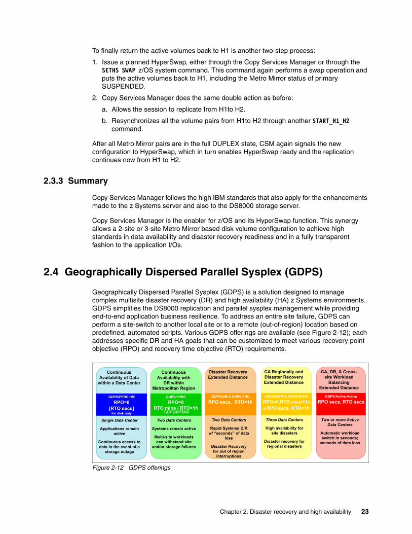
Geographically Dispersed Parallel Sysplex (GDPS) is a solution designed to manage complex multisite disaster recovery (DR) and high availability (HA) z Systems environments. GDPS simplifies the DS8000 replication and parallel sysplex management while providing end-to-end application business resilience. To address an entire site failure, GDPS can perform a site-switch to another local site or to a remote (out-of-region) location based on predefined, automated scripts. Various GDPS offerings are available (see Figure 2-12); each addresses specific DR and HA goals that can be customized to meet various recovery point objective (RPO) and recovery time objective (RTO) requirements.
Figure 2-12 GDPS offerings
Continuous Availability of Data
within a Data Center
Single Data Center
Applications remain active
Continuous access to data in the event of a
storage outage
GDPS/PPRC HMRPO=0
[RTO secs]for disk only
Disaster Recovery Extended Distance
Two Data Centers
Rapid Systems D/R w/ “seconds” of data
loss
Disaster Recoveryfor out of region
interruptions
GDPS/GM & GDPS/XRCRPO secs, RTO<1h
CA Regionally and Disaster Recovery Extended Distance
Three Data Centers
High availability for site disasters
Disaster recovery for regional disasters
GDPS/MGM & GDPS/MzGMRPO=0,RTO mins/<1h& RPO secs, RTO<1h
CA, DR, & Cross-site Workload
BalancingExtended Distance
Two or more Active Data Centers
Automatic workload switch in seconds;
seconds of data loss
GDPS/Active-ActiveRPO secs, RTO secs
Continuous Availability with
DR within Metropolitan Region
GDPS/PPRCRPO=0
RTO mins / RTO<1h
Two Data Centers
Systems remain active
Multi-site workloads can withstand site
and/or storage failures
GDPS/MTMM
Chapter 2. Disaster recovery and high availability 23
One difference between options is in the type of the DS8000 Copy Services that are used as a building block for DR and HA design. The following list provides more details about Copy Services that are used:
� GDPS/PPRC HyperSwap Manager (HM) and GDPS/PPRC are based on DS8000 synchronous data replication, Metro Mirror (known as PPRC).
� GDPS/GM is based on the DS8000 Global Mirror, asynchronous form of remote copy.
� GDPS/XRC uses asynchronous data replication, Extended Remote Copy (also known as zGM).
� GDPS/MGM uses both Metro Mirror and Global Mirror disk replication for a 3-site or 4-site DR and HA environment.
� GDPS/MTMM provides support for Multiple Target Metro Mirror on DS8000. GDPS/MTMM provides similar capabilities as those already available in GDPS/PPRC while extending PPRC management and HyperSwap capabilities to cover the two replication legs.
� GDPS/MzGM uses both Metro Mirror and XRC or zGM disk replication for a 3-site or 4-site DR and HA environment.
� GDPS Active/Active is a multisite HA/DR solution at virtually unlimited distances. This solution is based on software-based asynchronous mirroring between two active production sysplexes running the same applications with the ability to process workloads in either site.
For more information about GDPS and each option, see IBM GDPS Family: An Introduction to Concepts and Capabilities, SG24-6374.
2.4.1 GDPS and DS8000 synergy features
Almost all GDPS solutions (except for GDPS active/active) rely on IBM disk replication technologies used in the DS8000 storage family. This section provides information about the key DS8000 technologies that GDPS supports and uses.
Metro Mirror (PPRC) failover/failback supportWhen a primary disk failure occurs and the disks are switched to the secondary devices, failover/failback support eliminates the need to do a full copy when reestablishing replication in the opposite direction. Because the primary and secondary volumes are often in the same state when the freeze occurred, the only differences between the volumes are the updates that occur to the secondary devices after the switch. Failover processing sets the secondary devices to primary suspended status and starts change-recording for any subsequent changes made. When the mirror is reestablished with failback processing, the original primary devices become secondary devices and a resynchronization of changed tracks occurs.
GDPS/PPRC transparently uses the failover/failback capability. This support mitigates RPO exposures by reducing the amount of time needed to resynchronize mirroring after a HyperSwap. Of course, the resynchronization time depends on how long mirroring was suspended and the number of changed tracks that must be transferred.
GDPS now also supports Multi-Target Metro Mirror on the IBM DS8880 and DS8870. Initial support is for two synchronous copies from a single primary volume, also known as a Multi-Target Metro Mirror (MTMM) configuration. GDPS/MTMM provides similar capabilities as those already available in GDPS/PPRC while extending PPRC management and HyperSwap capabilities to cover the two replication legs.
24 IBM DS8880 and IBM z Systems Synergy
Global CopyGlobal Copy (also formerly known as PPRC-XD) is an asynchronous form of the DS8000 advanced copy functions. GDPS uses Global Copy rather than synchronous Metro Mirror (PPRC) to reduce the performance impact of certain remote copy operations that potentially involve a large amount of data. The replication links are typically sized for steady state update activity, but not for bulk synchronous replication, such as initial volume copy or resynchronization.
There is no need to perform initial copy or resynchronizations using synchronous copy because the secondary disks cannot be made consistent until all disks in the configuration reach the duplex state. Therefore, GDPS supports initial copy and resynchronization using asynchronous Global Copy. When GDPS initiates copy operations in asynchronous copy mode, GDPS monitors progress of the copy operation and when the volumes are near full duplex state, GDPS converts the replication from the asynchronous copy mode to synchronous. Initial copy or resynchronization using Global Copy eliminates the performance impact of synchronous mirroring on production workloads.
Exploitation of the asynchronous copy allows clients to establish or resynchronize mirroring during periods of high production workload, and can potentially reduce the time during which the configuration is exposed.
DS8000 Health Message AlertAn unplanned HyperSwap is invoked automatically by GDPS in case of a primary disk failure.
In addition to a disk problem being detected as a result of an I/O operation, also possible is for a primary disk subsystem to proactively report that it is experiencing an acute problem. The DS8000 systems have a special microcode function known as the Storage Controller Health Message Alert capability. It will alert z/OS when hardware events occur, generating a message and Event Notification Facility (ENF) signal as in Example 2-5.
Example 2-5 DS8880 Health Message Alert
IEA074I STORAGE CONTROLLER HEALTH,MC=20,TOKEN=1004,SSID=AB01, DEVICE NED=2107.961.IBM.75.0000000ABCD1.0100,PPRC SECONDARY CONTROLLER RECOVERY ACTION
Problems of different severities are reported by DS8000. Those problems that are classified as acute are also treated as HyperSwap triggers. After systems are swapped to use the secondary disks, the disk subsystem and operating system can try to perform recovery actions on the former primary without impacting the applications using those disks.
One main benefit of the Health Message Alert function is to reduce false freeze events. GDPS Freeze and Conditional Stop actions will query secondary disk subsystem to determine if systems can be allowed to continue in a freeze event.
Metro Mirror (PPRC) suspension (Summary Event Notification)A Metro Mirror suspension generates a message aggregation also known as Summary Event Notification. This aggregation dramatically reduces host interrupts and operator messages when Metro Mirror volume pair is suspended.
When GDPS performs a freeze, all primary devices in the Metro Mirror configuration suspend. This can result in significant State Change Interrupt (SCI) traffic and many messages in all of the systems. GDPS, in conjunction with z/OS 1.13 (and later) and microcode on the DS8000 disk systems, supports reporting suspensions in a summary message per DS8000 logical control unit (LCU) instead of at the individual device level.
Chapter 2. Disaster recovery and high availability 25
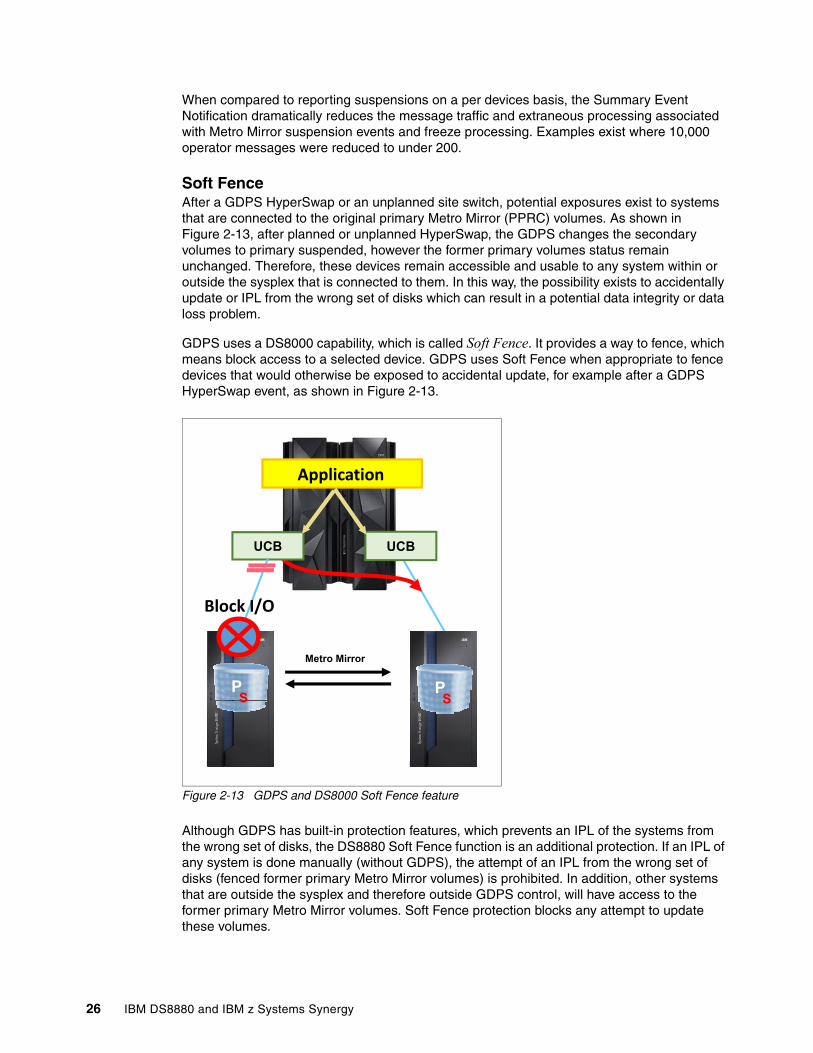
When compared to reporting suspensions on a per devices basis, the Summary Event Notification dramatically reduces the message traffic and extraneous processing associated with Metro Mirror suspension events and freeze processing. Examples exist where 10,000 operator messages were reduced to under 200.
Soft FenceAfter a GDPS HyperSwap or an unplanned site switch, potential exposures exist to systems that are connected to the original primary Metro Mirror (PPRC) volumes. As shown in Figure 2-13, after planned or unplanned HyperSwap, the GDPS changes the secondary volumes to primary suspended, however the former primary volumes status remain unchanged. Therefore, these devices remain accessible and usable to any system within or outside the sysplex that is connected to them. In this way, the possibility exists to accidentally update or IPL from the wrong set of disks which can result in a potential data integrity or data loss problem.
GDPS uses a DS8000 capability, which is called Soft Fence. It provides a way to fence, which means block access to a selected device. GDPS uses Soft Fence when appropriate to fence devices that would otherwise be exposed to accidental update, for example after a GDPS HyperSwap event, as shown in Figure 2-13.
Figure 2-13 GDPS and DS8000 Soft Fence feature
Although GDPS has built-in protection features, which prevents an IPL of the systems from the wrong set of disks, the DS8880 Soft Fence function is an additional protection. If an IPL of any system is done manually (without GDPS), the attempt of an IPL from the wrong set of disks (fenced former primary Metro Mirror volumes) is prohibited. In addition, other systems that are outside the sysplex and therefore outside GDPS control, will have access to the former primary Metro Mirror volumes. Soft Fence protection blocks any attempt to update these volumes.
Metro Mirror
Application
PS P
S
UCB UCB
Block I/O
26 IBM DS8880 and IBM z Systems Synergy
On Demand DumpWhen problems occur with disk subsystems, such as those that result in an unplanned HyperSwap, a mirroring suspension, or performance issues, a lack of diagnostic data from the time that the event occurs can result in difficulties in identifying the root cause of the problem. Taking a full statesave can lead to temporary disruption to host I/O. The On Demand Dump (ODD) capability of the DS8880 facilitates taking a nondisruptive statesave (NDSS) at the time such an event occurs. The DS8000 microcode does this automatically for certain events such as generating a dump of the primary disk system that triggers a freeze event and also allows an NDSS to be requested by an exploiter. This enables first failure data capture (FFDC) and thus ensures that diagnostic data is available to help problem determination.
GDPS provides support for taking an NDSS using the remote copy panels (or web GUI). In addition to this support, GDPS autonomically takes an NDSS if an unplanned freeze or HyperSwap event occurs.
Query Host AccessWhen a Metro Mirror (PPRC) disk pair is being established, the device that is the target (secondary) must not be used by any system. The same is true when establishing a FlashCopy relationship to a target device. If the target is in use, the establishment of the PPRC or FlashCopy relationship fails. When such failures occur, identifying which system is delaying the operation can be a tedious task. The Query Host Access DS8000 function provides the means to query and identify what system is using a selected device. This function is used by the IBM Device Support Facilities (ICKDSF) utility (see 4.5, “Volume formatting overwrite protection” on page 53), and also by GDPS.
GDPS adds its usability in several ways:
� Query Host Access identifies the LPAR that is using the selected device through the CPU serial number and LPAR number. For the operations staff to translate this information to a system or CPU and LPAR name is still a tedious job. GDPS does this translation and presents the operator with more readily usable information, avoiding this additional translation effort.
� When GDPS is requested to perform a PPRC or FlashCopy establish operation, GDPS first performs Query Host Access to determine whether the operation is expected to succeed or fail as a result of one or more target devices being in use. GDPS alerts the operator if the operation is expected to fail, and identifies the target devices in use and the LPARs holding them.
� GDPS continually monitors the target devices defined in the GDPS configuration and alerts operations that target devices are in use when they should not be. This allows operations to fix the reported problems in a timely manner.
� With GDPS, the operator can perform ad hoc Query Host Access to any selected device using the GDPS panels (or GUI).
Chapter 2. Disaster recovery and high availability 27
DS8000 Easy Tier Heat Map TransferIBM DS8000 Easy Tier and Heat Map Transfer (HMT) are described in 5.7, “Easy Tier” on page 80. Easy Tier HMT is the DS8000 capability to transfer the Easy Tier learning from a Metro Mirror (PPRC) primary to the secondary disk subsystem such that the secondary disk system can also be optimized based on this learning and will have similar performance characteristics in the HyperSwap event.
GDPS integrates support for HMT. The appropriate Heat Map Transfer actions (such as start and stop of the processing and reversing transfer direction) are incorporated into the GDPS managed processes. For example, if Metro Mirror is temporarily suspended by GDPS for a planned or unplanned secondary disk outage, HMT is also suspended, or if Metro Mirror direction is reversed as a result of a HyperSwap, HMT direction is also reversed.
As of GDPS 3.12 and later, HMT is supported for all available GDPS options (2-site, 3-site, and 4-site environments).
2.4.2 GDPS and DS8000 synergy summary
GDPS is specifically designed for a complex multi-site or single-site z Systems environments. It provides the capability to manage disk remote copy, to automate Parallel Sysplex operation tasks, and perform failure recovery from a single point of control in an easy and automated way. Continuous collaboration over many years between z Systems, GDPS, and DS8000 development teams delivered a robust HA and DR design that is commonly used among z Systems clients.
With its HyperSwap capability, GDPS is the ideal solution if you target for 99.9999% availability.
Moreover, it also allows clients to run disaster recovery tests more frequently without affecting production. The more you practice your DR process, the more confident you become in recovering your systems and applications if real disaster strikes.
28 IBM DS8880 and IBM z Systems Synergy
Chapter 3. Data protection and backup
Traditional data protection and backup typically rely on a point-in-time copy, which allows restoring data only from when that copy, or backup, was created. As the name implies, continuous data protection in contrast to traditional data protection and backup has no defined schedule. However, it is usually an asynchronously created copy, which does not necessarily guarantee consistent data at any one time. There are utilities and other software or middleware based functions available to overcome this shortcoming of continuous data backup.
Nevertheless, massive data backups still rely on a point-in-time backup copy combined with serialization efforts. For example, database subsystems can temporarily quiesce databases and related data sets, forcing a buffer flush to permanent storage. The challenge is then to create a backup copy as quickly as possible to make the database data sets available again. Several solutions were developed over time, but the basic and simplest approach is still to create a consistent backup as quickly as possible, and also instantly reusable.
With the DS8000, the foundation for this simple backup approach is based on the FlashCopy function. The next step was to develop software that could intelligently use FlashCopy to have a fast process to flash or snap a volume or data set.
With z/OS 1.5, IBM introduced the first edition of fast replication backup (FRBACKUP). DB2 is able to use this function for DB2 system-level backup and to control the serialization effort that guarantees a consistent set of the complete system level backup, including all DB2 table space and logs. DB2 also maintains its repository, for instance by updating the bootstrap data set (BSDS) to reflect all backup activity.
Over the years, FRBACKUP has been enhanced to the level that is now implemented in z/OS 2.2.
This chapter describes FRBACKUP and other backup solutions that use FlashCopy with DB2 and IBM IMS™, adding to the list of synergy items between z Systems server and DS8000 storage servers.
This chapter includes the following topics:
� Fast replication backup� Using FlashCopy with DB2 and IMS
3
© Copyright IBM Corp. 2015, 2017. All rights reserved. 29
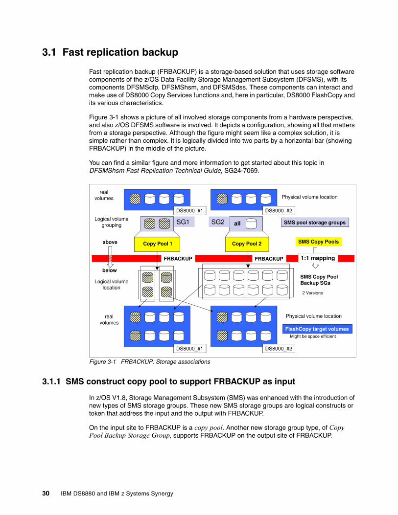
3.1 Fast replication backup
Fast replication backup (FRBACKUP) is a storage-based solution that uses storage software components of the z/OS Data Facility Storage Management Subsystem (DFSMS), with its components DFSMSdfp, DFSMShsm, and DFSMSdss. These components can interact and make use of DS8000 Copy Services functions and, here in particular, DS8000 FlashCopy and its various characteristics.
Figure 3-1 shows a picture of all involved storage components from a hardware perspective, and also z/OS DFSMS software is involved. It depicts a configuration, showing all that matters from a storage perspective. Although the figure might seem like a complex solution, it is simple rather than complex. It is logically divided into two parts by a horizontal bar (showing FRBACKUP) in the middle of the picture.
You can find a similar figure and more information to get started about this topic in DFSMShsm Fast Replication Technical Guide, SG24-7069.
Figure 3-1 FRBACKUP: Storage associations
3.1.1 SMS construct copy pool to support FRBACKUP as input
In z/OS V1.8, Storage Management Subsystem (SMS) was enhanced with the introduction of new types of SMS storage groups. These new SMS storage groups are logical constructs or token that address the input and the output with FRBACKUP.
On the input site to FRBACKUP is a copy pool. Another new storage group type, of Copy Pool Backup Storage Group, supports FRBACKUP on the output site of FRBACKUP.
SG2SG1
FRBACKUP 1:1 mappingFRBACKUP
volumesreal
Physical volume location
all
SMS Copy Pools
DS8000_#1 DS8000_#2
Logical volumegrouping
Copy Pool 1 Copy Pool 2
SMS pool storage groups
above
below
Physical volume location
FlashCopy target volumesvolumes
real
DS8000_#1 DS8000_#2
Logical volumelocation
SMS Copy PoolBackup SGs
2 Versions
Might be space efficient
below
30 IBM DS8880 and IBM z Systems Synergy
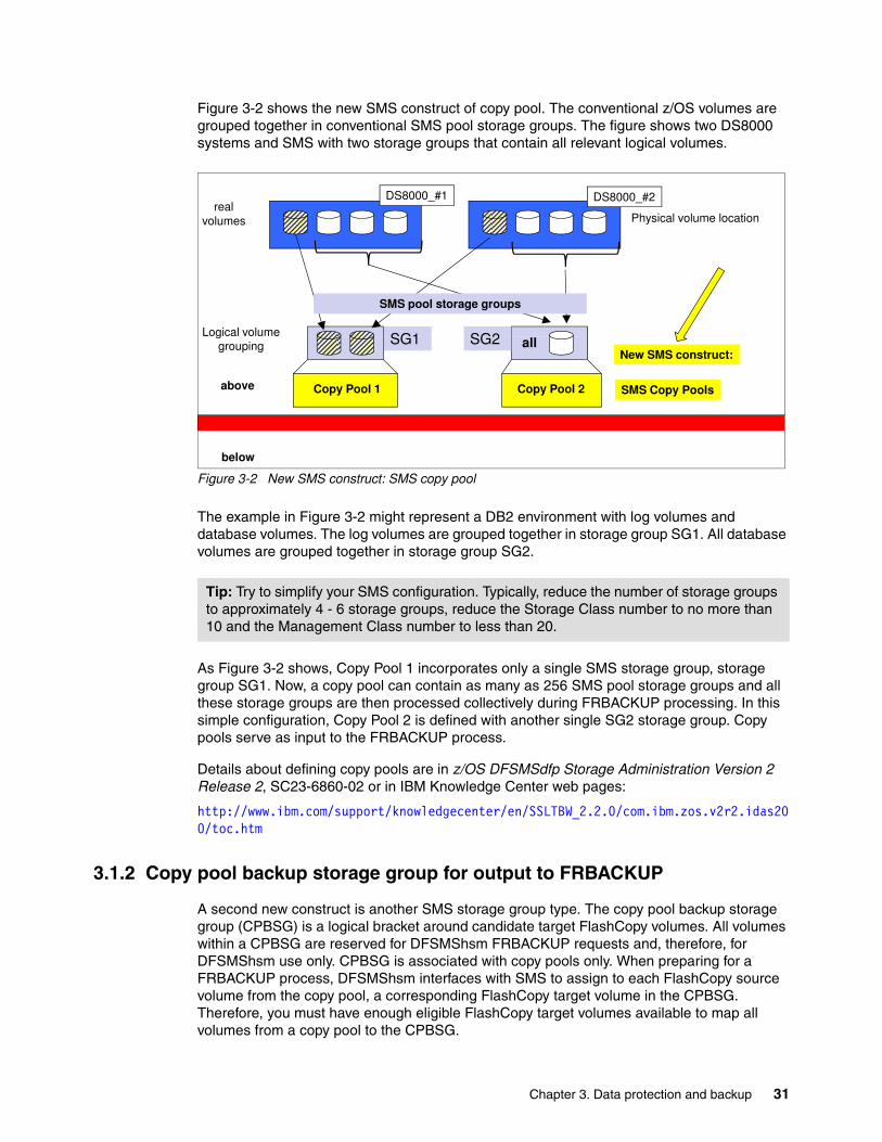
Figure 3-2 shows the new SMS construct of copy pool. The conventional z/OS volumes are grouped together in conventional SMS pool storage groups. The figure shows two DS8000 systems and SMS with two storage groups that contain all relevant logical volumes.
Figure 3-2 New SMS construct: SMS copy pool
The example in Figure 3-2 might represent a DB2 environment with log volumes and database volumes. The log volumes are grouped together in storage group SG1. All database volumes are grouped together in storage group SG2.
As Figure 3-2 shows, Copy Pool 1 incorporates only a single SMS storage group, storage group SG1. Now, a copy pool can contain as many as 256 SMS pool storage groups and all these storage groups are then processed collectively during FRBACKUP processing. In this simple configuration, Copy Pool 2 is defined with another single SG2 storage group. Copy pools serve as input to the FRBACKUP process.
Details about defining copy pools are in z/OS DFSMSdfp Storage Administration Version 2 Release 2, SC23-6860-02 or in IBM Knowledge Center web pages:
http://www.ibm.com/support/knowledgecenter/en/SSLTBW_2.2.0/com.ibm.zos.v2r2.idas200/toc.htm
3.1.2 Copy pool backup storage group for output to FRBACKUP
A second new construct is another SMS storage group type. The copy pool backup storage group (CPBSG) is a logical bracket around candidate target FlashCopy volumes. All volumes within a CPBSG are reserved for DFSMShsm FRBACKUP requests and, therefore, for DFSMShsm use only. CPBSG is associated with copy pools only. When preparing for a FRBACKUP process, DFSMShsm interfaces with SMS to assign to each FlashCopy source volume from the copy pool, a corresponding FlashCopy target volume in the CPBSG. Therefore, you must have enough eligible FlashCopy target volumes available to map all volumes from a copy pool to the CPBSG.
Tip: Try to simplify your SMS configuration. Typically, reduce the number of storage groups to approximately 4 - 6 storage groups, reduce the Storage Class number to no more than 10 and the Management Class number to less than 20.
SG2SG1
volumesreal
Physical volume location
DS8000_#2
Logical volume
DS8000_#1
SMS pool storage groups
SG2SG1 all
SMS Copy Pools
ggrouping
Copy Pool 1 Copy Pool 2above
New SMS construct:
below
Chapter 3. Data protection and backup 31
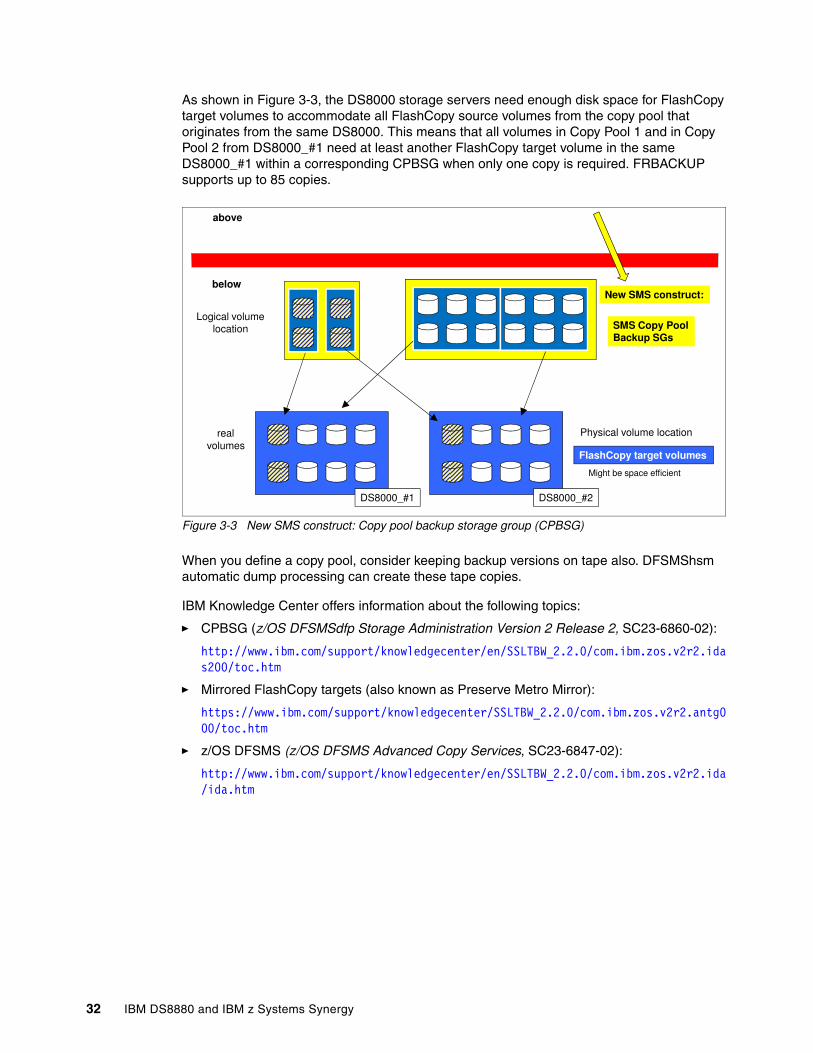
As shown in Figure 3-3, the DS8000 storage servers need enough disk space for FlashCopy target volumes to accommodate all FlashCopy source volumes from the copy pool that originates from the same DS8000. This means that all volumes in Copy Pool 1 and in Copy Pool 2 from DS8000_#1 need at least another FlashCopy target volume in the same DS8000_#1 within a corresponding CPBSG when only one copy is required. FRBACKUP supports up to 85 copies.
Figure 3-3 New SMS construct: Copy pool backup storage group (CPBSG)
When you define a copy pool, consider keeping backup versions on tape also. DFSMShsm automatic dump processing can create these tape copies.
IBM Knowledge Center offers information about the following topics:
� CPBSG (z/OS DFSMSdfp Storage Administration Version 2 Release 2, SC23-6860-02):
http://www.ibm.com/support/knowledgecenter/en/SSLTBW_2.2.0/com.ibm.zos.v2r2.idas200/toc.htm
� Mirrored FlashCopy targets (also known as Preserve Metro Mirror):
https://www.ibm.com/support/knowledgecenter/SSLTBW_2.2.0/com.ibm.zos.v2r2.antg000/toc.htm
� z/OS DFSMS (z/OS DFSMS Advanced Copy Services, SC23-6847-02):
http://www.ibm.com/support/knowledgecenter/en/SSLTBW_2.2.0/com.ibm.zos.v2r2.ida/ida.htm
Logical volumelocation SMS Copy Pool
Backup SGs
above
belowNew SMS construct:
Physical volume location
FlashCopy target volumesvolumes
real
DS8000_#1 DS8000_#2
Might be space efficient
32 IBM DS8880 and IBM z Systems Synergy
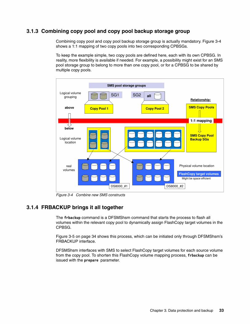
3.1.3 Combining copy pool and copy pool backup storage group
Combining copy pool and copy pool backup storage group is actually mandatory. Figure 3-4 shows a 1:1 mapping of two copy pools into two corresponding CPBSGs.
To keep the example simple, two copy pools are defined here, each with its own CPBSG. In reality, more flexibility is available if needed. For example, a possibility might exist for an SMS pool storage group to belong to more than one copy pool, or for a CPBSG to be shared by multiple copy pools.
Figure 3-4 Combine new SMS constructs
3.1.4 FRBACKUP brings it all together
The frbackup command is a DFSMShsm command that starts the process to flash all volumes within the relevant copy pool to dynamically assign FlashCopy target volumes in the CPBSG.
Figure 3-5 on page 34 shows this process, which can be initiated only through DFSMShsm’s FRBACKUP interface.
DFSMShsm interfaces with SMS to select FlashCopy target volumes for each source volume from the copy pool. To shorten this FlashCopy volume mapping process, frbackup can be issued with the prepare parameter.
SG2SG1
1:1 mapping
all
SMS Copy Pools
SMS Copy Pool
Logical volumegrouping
Copy Pool 1 Copy Pool 2
SMS pool storage groups
above
below
Relationship:
Physical volume location
FlashCopy target volumesvolumes
real
DS8000_#1 DS8000_#2
Logical volumelocation
pyBackup SGs
Might be space efficient
Chapter 3. Data protection and backup 33
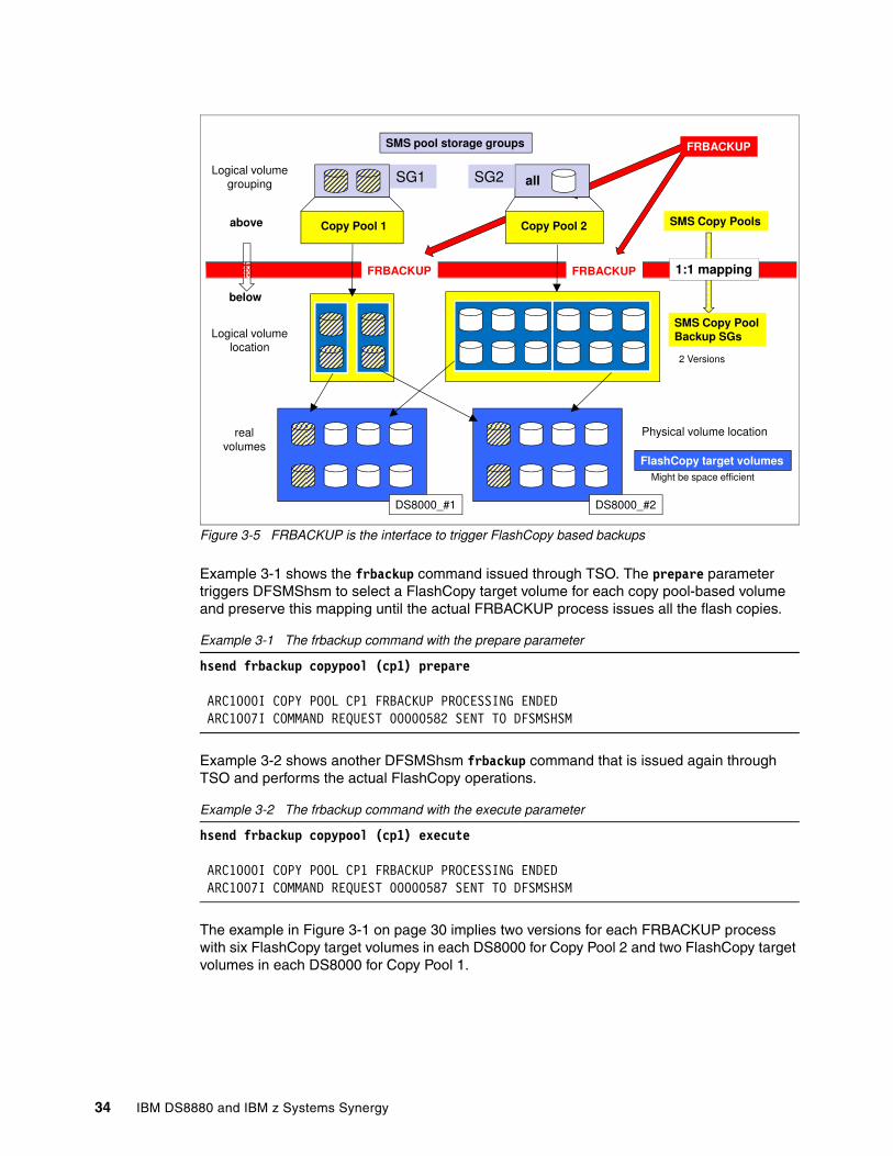
Figure 3-5 FRBACKUP is the interface to trigger FlashCopy based backups
Example 3-1 shows the frbackup command issued through TSO. The prepare parameter triggers DFSMShsm to select a FlashCopy target volume for each copy pool-based volume and preserve this mapping until the actual FRBACKUP process issues all the flash copies.
Example 3-1 The frbackup command with the prepare parameter
hsend frbackup copypool (cp1) prepare
ARC1000I COPY POOL CP1 FRBACKUP PROCESSING ENDED ARC1007I COMMAND REQUEST 00000582 SENT TO DFSMSHSM
Example 3-2 shows another DFSMShsm frbackup command that is issued again through TSO and performs the actual FlashCopy operations.
Example 3-2 The frbackup command with the execute parameter
hsend frbackup copypool (cp1) execute ARC1000I COPY POOL CP1 FRBACKUP PROCESSING ENDED ARC1007I COMMAND REQUEST 00000587 SENT TO DFSMSHSM
The example in Figure 3-1 on page 30 implies two versions for each FRBACKUP process with six FlashCopy target volumes in each DS8000 for Copy Pool 2 and two FlashCopy target volumes in each DS8000 for Copy Pool 1.
SG2SG1
FRBACKUP 1:1 mappingFRBACKUP
all
SMS Copy Pools
SMS Copy Pool
Logical volumegrouping
Copy Pool 1 Copy Pool 2
SMS pool storage groups
above
below
FRBACKUP
Physical volume location
FlashCopy target volumesvolumes
real
DS8000_#1 DS8000_#2
Logical volumelocation
pyBackup SGs
2 Versions
Might be space efficient
34 IBM DS8880 and IBM z Systems Synergy
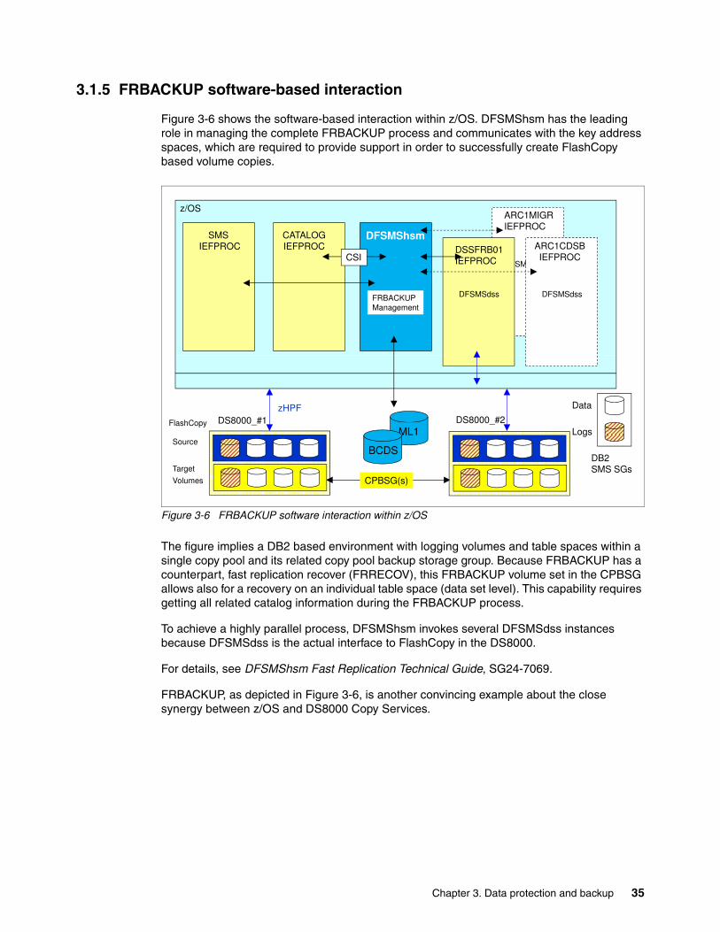
3.1.5 FRBACKUP software-based interaction
Figure 3-6 shows the software-based interaction within z/OS. DFSMShsm has the leading role in managing the complete FRBACKUP process and communicates with the key address spaces, which are required to provide support in order to successfully create FlashCopy based volume copies.
Figure 3-6 FRBACKUP software interaction within z/OS
The figure implies a DB2 based environment with logging volumes and table spaces within a single copy pool and its related copy pool backup storage group. Because FRBACKUP has a counterpart, fast replication recover (FRRECOV), this FRBACKUP volume set in the CPBSG allows also for a recovery on an individual table space (data set level). This capability requires getting all related catalog information during the FRBACKUP process.
To achieve a highly parallel process, DFSMShsm invokes several DFSMSdss instances because DFSMSdss is the actual interface to FlashCopy in the DS8000.
For details, see DFSMShsm Fast Replication Technical Guide, SG24-7069.
FRBACKUP, as depicted in Figure 3-6, is another convincing example about the close synergy between z/OS and DS8000 Copy Services.
DFSMShsmSMS IEFPROC
CATALOGIEFPROC
ARC1MIGRIEFPROC
z/OS
FRBACKUPManagement
CSIDFSMSdss
DSSFRB01IEFPROC
DFSMSdss
ARC1CDSBIEFPROC
DFSMSdss
DB2SMS SGs
Logs
Data
Target
Volumes
ML1
BCDS
DS8000_#2FlashCopy
Source
zHPFDS8000_#1
CPBSG(s)
Chapter 3. Data protection and backup 35
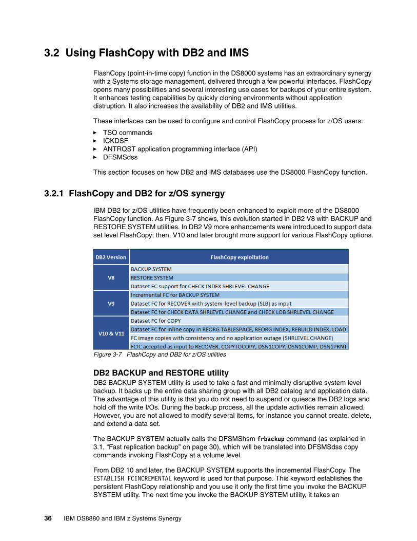
3.2 Using FlashCopy with DB2 and IMS
FlashCopy (point-in-time copy) function in the DS8000 systems has an extraordinary synergy with z Systems storage management, delivered through a few powerful interfaces. FlashCopy opens many possibilities and several interesting use cases for backups of your entire system. It enhances testing capabilities by quickly cloning environments without application distruption. It also increases the availability of DB2 and IMS utilities.
These interfaces can be used to configure and control FlashCopy process for z/OS users:
� TSO commands� ICKDSF� ANTRQST application programming interface (API)� DFSMSdss
This section focuses on how DB2 and IMS databases use the DS8000 FlashCopy function.
3.2.1 FlashCopy and DB2 for z/OS synergy
IBM DB2 for z/OS utilities have frequently been enhanced to exploit more of the DS8000 FlashCopy function. As Figure 3-7 shows, this evolution started in DB2 V8 with BACKUP and RESTORE SYSTEM utilities. In DB2 V9 more enhancements were introduced to support data set level FlashCopy; then, V10 and later brought more support for various FlashCopy options.
Figure 3-7 FlashCopy and DB2 for z/OS utilities
DB2 BACKUP and RESTORE utilityDB2 BACKUP SYSTEM utility is used to take a fast and minimally disruptive system level backup. It backs up the entire data sharing group with all DB2 catalog and application data. The advantage of this utility is that you do not need to suspend or quiesce the DB2 logs and hold off the write I/Os. During the backup process, all the update activities remain allowed. However, you are not allowed to modify several items, for instance you cannot create, delete, and extend a data set.
The BACKUP SYSTEM actually calls the DFSMShsm frbackup command (as explained in 3.1, “Fast replication backup” on page 30), which will be translated into DFSMSdss copy commands invoking FlashCopy at a volume level.
From DB2 10 and later, the BACKUP SYSTEM supports the incremental FlashCopy. The ESTABLISH FCINCREMENTAL keyword is used for that purpose. This keyword establishes the persistent FlashCopy relationship and you use it only the first time you invoke the BACKUP SYSTEM utility. The next time you invoke the BACKUP SYSTEM utility, it takes an
36 IBM DS8880 and IBM z Systems Synergy
incremental FlashCopy from the physical background copy. This persistent incremental FlashCopy relationship can be terminated with BACKUP SYSTEM END FCINCREMENTAL parameter.
After the BACKUP SYSTEM completes, the restore is done using the RESTORE SYSTEM utility which can restore a complete system. Similar to the BACKUP SYSTEM utility, RESTORE SYSTEM calls the DFSMShsm FRRECOV command, which is accordingly translated into DFSMSdss copy commands invoking FlashCopy in the background.
Another possibility is to restore an individual DB2 object (table space or index) from the full system backup. Unlike the full BACKUP SYSTEM and RESTORE SYSTEM, which use the FlashCopy on the volume level, when the single DB2 object is recovered, the data set level FlashCopy is used. The SYSTEM_LEVEL_BACKUPS parameter should be YES (default is NO).
And again, DFSMShsm is used in the background to extract the data set from the volume level FlashCopy taken with BACKUP SYSTEM.
DB2 FlashCopy image copy utilityDB2 10 and later has an option to invoke data set level FlashCopy to create image copies. The Image Copy utility supports it, however, the data set level FlashCopy can be exploited by any DB2 utility that creates an inline image copy, such as a DB2 reorg, load, rebuild index, and reorg index. By using FlashCopy in the background, the z Systems CPU is off-loaded to the DS8000 FlashCopy process. In addition, the Image Copy utility is completed as soon at the FlashCopy relationship is established.
FlashCopy image copy can be taken concurrently with share level reference Image Copies, and without any impact on the applications.
Unlike the BACKUP SYSTEM, FlashCopy image copy invokes DFSMSdss directly. Because DFSMShsm is not involved, there is no need for planning your data placement (for example, ICF catalogs and so on). The only requirement is that all DB2 volumes must be SMS managed.
As soon as the FlashCopy image copy is created, it is available for restoring. And again, the recover utility, when it restores the FlashCopy image copy object, invokes FlashCopy through DFSMSdss.
Check Index, Check Data, and Check LOB utilitiesAlthough the Check Index, Check Data, and Check LOB utilities are not used frequently, they are some of the most important utilities regarding data corruption analysis. They can help you find the level of corruption and the best recovery processes. Here, the FlashCopy synergy with these Check utilities plays an important role. In the situation where you suspect data corruption, a prompt investigation is critical. Running the Check utilities while the application is running can save enormous time.
FlashCopy provides an option to run a Check utility nondisruptively with share level change (SHRLEVEL CHANGE parameter) included. Using this option will create a shadow data sets of data, indexes, and large objects (LOB) that can be checked by the utility using the DSFSMdss copy command (FlashCopy). As soon as the FlashCopy is established (several seconds), the Check utility starts using the shadow data set (FlashCopy target data set). The shadow data set is in read-only mode only during the time that is required for the FlashCopy relationship to be established. After the DFSMSdss confirms that the FlashCopy is established, full read and write access to the data set is restored.
Chapter 3. Data protection and backup 37
Therefore, without FlashCopy and the Check utility with share level access, the shadow data set is be created with the standard I/O using the z Systems resources rather than DS8000. This process can be disruptive for the application. To avoid this situation, a suggestion is to update the ZPARM FlashCopy fastreplication keyword to REQUIRED, rather than PREFFERED, which is default value in DB2 V10 and later. This parameter guarantees that the FlashCopy will be used every time. If problems occur while invoking the FlashCopy, the Check utility fails, which is better than suffering any application outage.
3.2.2 FlashCopy and IMS for z/OS synergy
Various IMS utilities, as is the case with DB2, use DFSMSdss to invoke the DS8000 FlashCopy function. This section provides information about IMS High Performance Image Copy (IMS HP IC) used for IMS backup and restore.
IMS High Performance Image Copy (IMS HP IC)IMS HP IC provides fast back up and recovery of database data. Although it includes many services, we focus on Advanced Image Copy Services, which allow IMS HP IC to produce faster image copies and to increase availability time for IMS databases.
The Advanced Image Copy Services use the DFSMSdss cross-memory application programming interface (API), ADRXMAIA, to process the DFSMSdss DUMP and COPY commands. These commands allow IMS HP IC to use the DS8000 FlashCopy advanced point-in-time copy function.
The FlashCopy and IMS synergy allows you to back up a database or any collection of data at a point in time and with minimum downtime for the database. The database is unavailable only long enough for DFSMSdss to initialize a FlashCopy relationship for the data (data set level FlashCopy), which is a small fraction of the time required for a complete backup. The copy that is made does not include any update activity. As soon as the FlashCopy relationship is established, DFSMSdss releases all the serialization it holds on the data, informs the Advanced Image Copy services about it so that update activity can resume, and begins reading the data.
38 IBM DS8880 and IBM z Systems Synergy
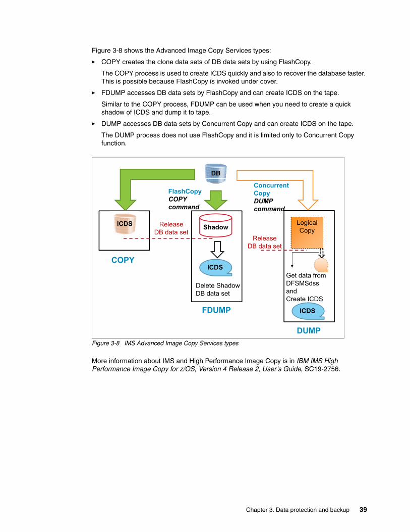
Figure 3-8 shows the Advanced Image Copy Services types:
� COPY creates the clone data sets of DB data sets by using FlashCopy.
The COPY process is used to create ICDS quickly and also to recover the database faster. This is possible because FlashCopy is invoked under cover.
� FDUMP accesses DB data sets by FlashCopy and can create ICDS on the tape.
Similar to the COPY process, FDUMP can be used when you need to create a quick shadow of ICDS and dump it to tape.
� DUMP accesses DB data sets by Concurrent Copy and can create ICDS on the tape.
The DUMP process does not use FlashCopy and it is limited only to Concurrent Copy function.
Figure 3-8 IMS Advanced Image Copy Services types
More information about IMS and High Performance Image Copy is in IBM IMS High Performance Image Copy for z/OS, Version 4 Release 2, User’s Guide, SC19-2756.
Shadow Logical
Copy
FlashCopyCOPYcommand
ConcurrentCopyDUMPcommand
Release
DB data setRelease
DB data set
ICDS
Delete Shadow
DB data set
Get data from
DFSMSdss
and
Create ICDS
ICDS
COPY
FDUMP
DUMP
DB
ICDS
Chapter 3. Data protection and backup 39

40 IBM DS8880 and IBM z Systems Synergy
Chapter 4. Management and configuration
This chapter describes enhancements in z/OS that help to simplify storage management, leaving it to the system to automatically and autonomically manage the storage. The foundation to reach this goal was developed through system-managed storage and has been available since 1989. Enhancements over the past years to today’s z/OS Version 2 level have perfected the storage software within z/OS.
The focus in this chapter is on storage pool designs and on particular enhancements jointly developed by the z/OS and DS8000 development teams to achieve more synergy between both units.
This chapter includes the following topics:
� Storage pool design considerations (from z/OS and DS8000 storage server perspectives)� Extended address volume (EAV) V2� Dynamic volume expansion (DVE)� Quick initialization� Volume formatting overwrite protection� Channel paths and control-unit-initiated reconfiguration� CKD thin provisioning� DSCLI on z/OS
4
© Copyright IBM Corp. 2015, 2017. All rights reserved. 41
4.1 Storage pool design considerations
Storage pool design considerations were always a source of debate. Discussions originated in the early days when customers discovered that they could not manually manage the growing numbers of their disk-based volumes.
IBM responded to requirements to address this challenge by introducing system-managed storage and its corresponding system storage software. The approach was to no longer necessarily focus on volume awareness and rather turn to a pool concept. The pool was the container for many volumes and disk storage was able to be managed on a pool level.
Eventually storage pool design considerations also evolved with the introduction of storage systems, such as the DS8000, offering other possibilities.
This section covers both views, system-managed storage and DS8000, and how both are combined to contribute to the synergy between z Systems server and DS8000 storage servers.
4.1.1 Storage pool design considerations within z/OS
System storage software, such as Data Facility Storage Management Subsystem (DFSMS), manages information: from creating a file or data set, its initial placement in the storage hierarchy, through its entire lifecycle until the file is eventually deleted. The z/OS Storage Management Subsystem (SMS), can automate management storage tasks and reduce the related costs. This is achieved through a policy-based data management, availability management, space management, and even performance management, which DFSMS provides in an autonomic fashion. Ultimately, it is complemented by the DS8000 disk storage server and its rich variety of functions that work well with DFSMS and its components, as described in 4.1.3, “Combining SMS storage groups and DS8000 extent pools” on page 46.
All of this starts with the initial placement of a newly allocated file within a storage hierarchy, and includes consideration for storage tiers in the DS8000 where the data reside. to each individual file, SMS assigns policy-based attributes. Those attributes may change over the lifecycle of that file.
Besides logically grouping attributes such as the SMS Data Class (DC), SMS Storage Class (SC), and SMS Management Class (MC) constructs, SMS also has the concept of Storage Group (SG).
Files finally are assigned to an SG or set of SGs. Ideally the criteria for where to place the file should be solely dictated by the SC attributes, and is controlled by the last Automatic Class Selection (ACS) routine. After an optional DC ACS routine, a mandatory SC ACS routine, followed by another optional MC ACS routine, this chain of ACS routines is concluded by the SG ACS routine. The result of the SG ACS routine finally ends in a list of candidate volumes where this file will be placed. Behind this candidate volume list is sophisticated logic to create the volume list. z/OS components and measurements are involved to review this volume list to finally identify the optimal volume for the file.
So, the key construct from a pooling viewpoint is the SMS SG. The preferred approach was always to create only a small number of SMS SGs and to populate each SMS SG with as many volumes as possible. This approach delegates to the system software the control for how to use and populate each single volume within the SMS SG. The system software has all the information about the configuration and the capabilities of each storage technology within the SMS SG. Performance-related service-level requirements can be addressed by SC attributes.
42 IBM DS8880 and IBM z Systems Synergy
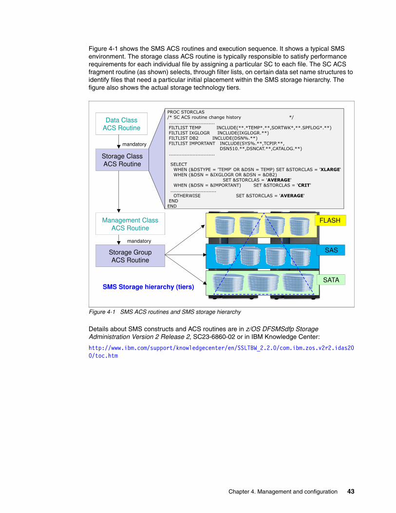
Figure 4-1 shows the SMS ACS routines and execution sequence. It shows a typical SMS environment. The storage class ACS routine is typically responsible to satisfy performance requirements for each individual file by assigning a particular SC to each file. The SC ACS fragment routine (as shown) selects, through filter lists, on certain data set name structures to identify files that need a particular initial placement within the SMS storage hierarchy. The figure also shows the actual storage technology tiers.
Figure 4-1 SMS ACS routines and SMS storage hierarchy
Details about SMS constructs and ACS routines are in z/OS DFSMSdfp Storage Administration Version 2 Release 2, SC23-6860-02 or in IBM Knowledge Center:
http://www.ibm.com/support/knowledgecenter/en/SSLTBW_2.2.0/com.ibm.zos.v2r2.idas200/toc.htm
��������������������� ������������������� ��������������������������������������������������������������������������������������� !�"������������#����$%�#�������&����'���������(&�&��������� !�"�(&�&����'��������������������������������!)*������������ !�"!��+���'�������������������������������������������������� !�"�,�+���#��������#��������������
!��-./���#!�������#���&���'���������������������������������
�����������������$0���"1!��,���2�3����4����1!���2�����'�����1�������2�3������4��$0���"1!���2�1�(&�&�����1!���2�1!)*'
����1�������2�3�5�����3$0���"1!���2�1��������'������������1�������2�3��3�������������������������������0��$������������������������������1�������2�3�5�����3�
��!�����������������������������������������������������������!
Storage ClassACS Routine
Data ClassACS Routine
mandatory
��!�
Storage GroupACS Routine
Management ClassACS Routine
SMS Storage hierarchy (tiers)
FLASH
SAS
SATA
mandatory
Chapter 4. Management and configuration 43
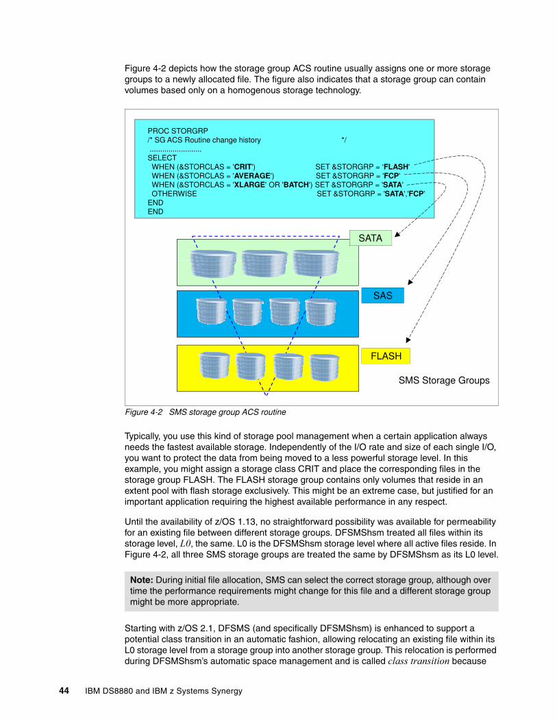
Figure 4-2 depicts how the storage group ACS routine usually assigns one or more storage groups to a newly allocated file. The figure also indicates that a storage group can contain volumes based only on a homogenous storage technology.
Figure 4-2 SMS storage group ACS routine
Typically, you use this kind of storage pool management when a certain application always needs the fastest available storage. Independently of the I/O rate and size of each single I/O, you want to protect the data from being moved to a less powerful storage level. In this example, you might assign a storage class CRIT and place the corresponding files in the storage group FLASH. The FLASH storage group contains only volumes that reside in an extent pool with flash storage exclusively. This might be an extreme case, but justified for an important application requiring the highest available performance in any respect.
Until the availability of z/OS 1.13, no straightforward possibility was available for permeability for an existing file between different storage groups. DFSMShsm treated all files within its storage level, L0, the same. L0 is the DFSMShsm storage level where all active files reside. In Figure 4-2, all three SMS storage groups are treated the same by DFSMShsm as its L0 level.
Starting with z/OS 2.1, DFSMS (and specifically DFSMShsm) is enhanced to support a potential class transition in an automatic fashion, allowing relocating an existing file within its L0 storage level from a storage group into another storage group. This relocation is performed during DFSMShsm’s automatic space management and is called class transition because
Note: During initial file allocation, SMS can select the correct storage group, although over time the performance requirements might change for this file and a different storage group might be more appropriate.
PROC STORGRP /* SG ACS Routine change history */......................... SELECTWHEN (&STORCLAS = 'CRIT') SET &STORGRP = ‘FLASH' WHEN (&STORCLAS = 'AVERAGE') SET &STORGRP = 'FCP'WHEN (&STORCLAS = 'XLARGE' OR 'BATCH') SET &STORGRP = 'SATA'OTHERWISE SET &STORGRP = 'SATA','FCP'
ENDEND
SATA
FLASH
SAS
SMS Storage Groups
44 IBM DS8880 and IBM z Systems Synergy
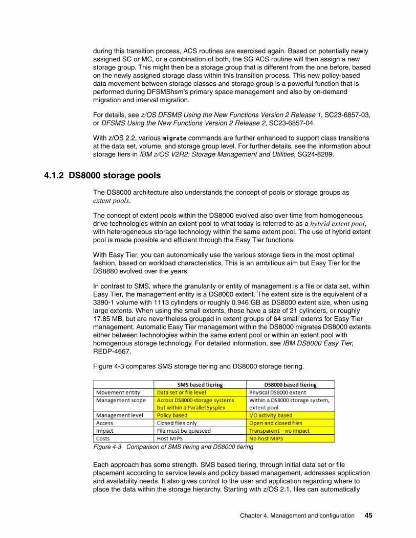
during this transition process, ACS routines are exercised again. Based on potentially newly assigned SC or MC, or a combination of both, the SG ACS routine will then assign a new storage group. This might then be a storage group that is different from the one before, based on the newly assigned storage class within this transition process. This new policy-based data movement between storage classes and storage group is a powerful function that is performed during DFSMShsm’s primary space management and also by on-demand migration and interval migration.
For details, see z/OS DFSMS Using the New Functions Version 2 Release 1, SC23-6857-03, or DFSMS Using the New Functions Version 2 Release 2, SC23-6857-04.
With z/OS 2.2, various migrate commands are further enhanced to support class transitions at the data set, volume, and storage group level. For further details, see the information about storage tiers in IBM z/OS V2R2: Storage Management and Utilities, SG24-8289.
4.1.2 DS8000 storage pools
The DS8000 architecture also understands the concept of pools or storage groups as extent pools.
The concept of extent pools within the DS8000 evolved also over time from homogeneous drive technologies within an extent pool to what today is referred to as a hybrid extent pool, with heterogeneous storage technology within the same extent pool. The use of hybrid extent pool is made possible and efficient through the Easy Tier functions.
With Easy Tier, you can autonomically use the various storage tiers in the most optimal fashion, based on workload characteristics. This is an ambitious aim but Easy Tier for the DS8880 evolved over the years.
In contrast to SMS, where the granularity or entity of management is a file or data set, within Easy Tier, the management entity is a DS8000 extent. The extent size is the equivalent of a 3390-1 volume with 1113 cylinders or roughly 0.946 GB as DS8000 extent size, when using large extents. When using the small extents, these have a size of 21 cylinders, or roughly 17.85 MB, but are nevertheless grouped in extent groups of 64 small extents for Easy Tier management. Automatic Easy Tier management within the DS8000 migrates DS8000 extents either between technologies within the same extent pool or within an extent pool with homogenous storage technology. For detailed information, see IBM DS8000 Easy Tier, REDP-4667.
Figure 4-3 compares SMS storage tiering and DS8000 storage tiering.
Figure 4-3 Comparison of SMS tiering and DS8000 tiering
Each approach has some strength. SMS based tiering, through initial data set or file placement according to service levels and policy based management, addresses application and availability needs. It also gives control to the user and application regarding where to place the data within the storage hierarchy. Starting with z/OS 2.1, files can automatically
Chapter 4. Management and configuration 45

transition between different SMS storage groups. This capability currently requires that the file not be open to an active application.
Easy Tier, from that standpoint, can relocate DS8000 extents without affecting a file that might be in use by an application.
Easy Tier does not understand application needs immediately. Its intention is rather to use the available storage technology in an economical fashion, to use expensive flash memory when the performance impact on HDD based technology with its latency might hurt an application.
4.1.3 Combining SMS storage groups and DS8000 extent pools
Combining both tiering approaches is possible, as shown in Figure 4-4.
Figure 4-4 SMS storage groups with and without mixed storage technology
This figure shows four potential SMS storage groups. Storage group Flash is intended to protect crucial and important files from being potentially hurt by automatic Easy Tier. Therefore, this storage group has its volumes solely defined in an DS8000 extent pool that consists of only flash memory, only SSD technology, or both. Through SMS, class transition storage administration can automatically relocate files according the application needs and requirements. This might be especially helpful to address important applications that can run only at month-end or quarterly. But then, they must have the best available performance, which the configuration can provide.
The Ent storage group has all its volumes defined within DS8000 extent pools containing enterprise level HDDs (SAS based, 10K/15K rpm). Typically, HDDs provide sufficient performance and usually z Systems controlled I/O is, anyway, using the DS8000 cache storage so efficiently that it can provide good I/O performance because of high cache-hit ratios.
Flash
HybridEnt
Flash
DS80000 extentData set / file
EasyTier
SMSClass
Transition
Nearline
EntEasyTier
46 IBM DS8880 and IBM z Systems Synergy
A nearline SMS storage group uses high-capacity 7200-rpm SAS-based HDDs. All related volumes are defined in DS8000 extent pools containing 7.2K HDDs only. To that storage tier, SMS can direct files that do not need high performance and require the least I/O service time.
The fourth SMS storage group has all its volumes defined in DS8000 hybrid extent pools, which might contain (Figure 4-4 on page 46 shows) SAS HDDs and also some flash technology. To here, SMS can allocate files that show a regular load pattern but with different I/O behavior and I/O skews. However, Easy Tier in automatic mode can, over time, see the I/O skew and might start moving extents within the pool. The Easy Tier intratier capability will relocate certain extents from overloaded ranks to ranks with less activity within the affected extent pool.
So, combining SMS Storage Groups and DS8000 Easy Tier tiering approaches might lead to the best achievable results from a total systems perspective. This proves another tight integration between z Systems and DS8000 to achieve to best possible results in an economical fashion with highly automated and transparent functions serving the z Systems customers.
4.2 Extended address volume (EAV) V2
Today’s large storage facilities tend to expand to larger CKD volume capacities. Some installations are nearing or beyond the z/OS addressable unit control block (UCB) 64 KB limitation disk storage. Because of the four-digit device addressing limitation, one must define larger CKD volumes by increasing the number of cylinders per volume.
EAV V1 supports volumes with up to 262,668 cylinders. EAV V2 supports up to 1,182,006 cylinders (about 1 TB).
With the introduction of EAVs, the addressing changed from track to cylinder addressing. The partial change from track to cylinder addressing creates the following address areas on EAV volumes:
� Track Managed Space: The area on an EAV that is located within the first 65,520 cylinders. The use of the 16-bit cylinder addressing allows a theoretical maximum address of 65,535 cylinders. To allocate more cylinders, you must have a new format to address the area above 65,520 cylinders.
For 16-bit cylinder numbers, the existing track address format is CCCCHHHH:
– HHHH: 16-bit track number– CCCC: 16-bit track cylinder
� Cylinder Managed Space: The area on an EAV that is located above the first 65,520 cylinders. This space is allocated in multicylinder units (MCUs), which currently have a size of 21 cylinders. A new cylinder-track address format addresses the extended capacity on an EAV.
For 28-bit cylinder numbers, the format is CCCCcccH:
– CCCC: The low order 16 bits of a 28-bit cylinder number– ccc: The high order 12 bits of a 28-bit cylinder number– H: A 4-bit track number (0 - 14)
Chapter 4. Management and configuration 47
The z/OS components and products now support 1,182,006 cylinders:
� DS8000 and z/OS V1.R12 or later support CKD EAV volume sizes:
– 3390 Model A: 1 to 1,182,006 cylinders (approximately 1004 TB addressable storage)– 3390 Model A: Up to 1062 x 3390 Model 1 (Four times the size of EAV R1)
� Configuration granularity:
– 1-cylinder boundary sizes: 1 to 56,520 cylinders– 1113-cylinder boundary sizes: 56,763 (51 x 1113) to 1,182,006 (1062 x 1113) cylinders
The size of an existing Mod 3/9/A volume can be increased to its maximum supported size by using dynamic volume expansion (DVE). See 4.3, “Dynamic volume expansion (DVE)” on page 51.
The volume table copy (VTOC) allocation method for an EAV volume was changed compared to the VTOC used for traditional smaller volumes. The size of an EAV VTOC index was increased four-fold, and now has 8192 blocks instead of 2048 blocks. Because no space remains inside the Format 1 data set control block (DSCB), new DSCB formats (Format 8 and Format 9) were created to protect existing programs from seeing unexpected track addresses. These DSCBs are called extended attribute DSCBs. Format 8 and 9 DSCBs are new for EAV. The existing Format 4 DSCB also was changed to point to the new Format 8 DSCB.
4.2.1 Data set type dependencies on an EAV R2
EAV R2 includes the following data set type dependencies:
� All Virtual Storage Access Method (VSAM) sequential data set types: Extended and large format, basic direct access method (BDAM), partitioned data set (PDS), partitioned data set extended (PDSE), VSAM volume data set (VVDS), and basic catalog structure (BCS) can be placed on the extended addressing space (EAS), which is cylinder managed space, of an EAV R2 volume that is running on z/OS V1.12 and later. Consider this information:
– Includes all VSAM data types, such as key-sequenced data set (KSDS), relative record data set (RRDS), entry-sequenced data set (ESDS), linear data set, and IBM DB2, IBM IMS, IBM CICS®, and z Systems file system (zFS) data sets.
– The VSAM data sets placed on an EAV volume can be Storage Management Subsystem (SMS) or non-SMS managed.
� For an EAV Release 2 volume, the following data sets might exist, but are not eligible to have extents in the extended address space (cylinder managed space):
– VSAM data sets with incompatible control area (CA) sizes– VTOC (it is still restricted to the first 64K-1 tracks)– VTOC index– Page data sets– A VSAM data set with embedded or keyrange attributes is currently not supported– Hierarchical file system (HFS) file system– SYS1.NUCLEUS
All other data sets can be placed on an EAV R2 EAS.
In the current releases, you can expand all Mod 3/9/A to a large EAV 2 by using DVE. For a sequential data set, VTOC reformat is run automatically if REFVTOC=ENABLE is enabled in the DEVSUPxx parmlib member.
48 IBM DS8880 and IBM z Systems Synergy
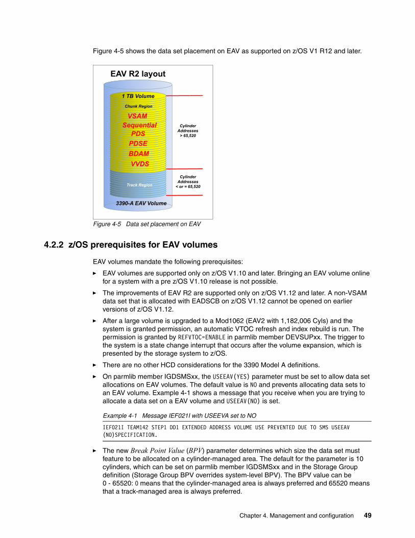
Figure 4-5 shows the data set placement on EAV as supported on z/OS V1 R12 and later.
Figure 4-5 Data set placement on EAV
4.2.2 z/OS prerequisites for EAV volumes
EAV volumes mandate the following prerequisites:
� EAV volumes are supported only on z/OS V1.10 and later. Bringing an EAV volume online for a system with a pre z/OS V1.10 release is not possible.
� The improvements of EAV R2 are supported only on z/OS V1.12 and later. A non-VSAM data set that is allocated with EADSCB on z/OS V1.12 cannot be opened on earlier versions of z/OS V1.12.
� After a large volume is upgraded to a Mod1062 (EAV2 with 1,182,006 Cyls) and the system is granted permission, an automatic VTOC refresh and index rebuild is run. The permission is granted by REFVTOC=ENABLE in parmlib member DEVSUPxx. The trigger to the system is a state change interrupt that occurs after the volume expansion, which is presented by the storage system to z/OS.
� There are no other HCD considerations for the 3390 Model A definitions.
� On parmlib member IGDSMSxx, the USEEAV(YES) parameter must be set to allow data set allocations on EAV volumes. The default value is NO and prevents allocating data sets to an EAV volume. Example 4-1 shows a message that you receive when you are trying to allocate a data set on a EAV volume and USEEAV(NO) is set.
Example 4-1 Message IEF021I with USEEVA set to NO
IEF021I TEAM142 STEP1 DD1 EXTENDED ADDRESS VOLUME USE PREVENTED DUE TO SMS USEEAV (NO)SPECIFICATION.
� The new Break Point Value (BPV) parameter determines which size the data set must feature to be allocated on a cylinder-managed area. The default for the parameter is 10 cylinders, which can be set on parmlib member IGDSMSxx and in the Storage Group definition (Storage Group BPV overrides system-level BPV). The BPV value can be 0 - 65520: 0 means that the cylinder-managed area is always preferred and 65520 means that a track-managed area is always preferred.
3390-A EAV Volume
EAV R2 layout
CylinderAddresses
< or = 65,520
CylinderAddresses
> 65,520
Chunk Region
Track Region
1 TB Volume
VSAMSequential
PDSEBDAMVVDS
PDS
Chapter 4. Management and configuration 49
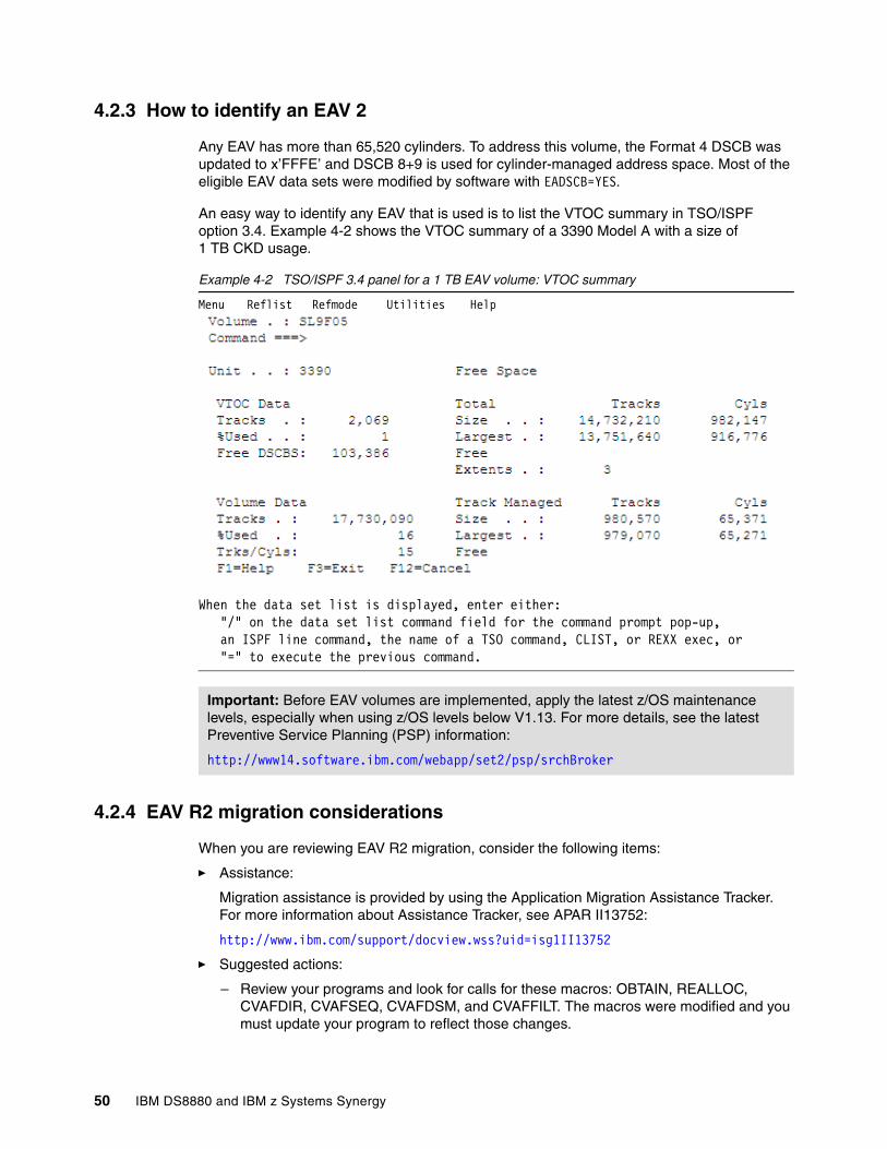
4.2.3 How to identify an EAV 2
Any EAV has more than 65,520 cylinders. To address this volume, the Format 4 DSCB was updated to x’FFFE’ and DSCB 8+9 is used for cylinder-managed address space. Most of the eligible EAV data sets were modified by software with EADSCB=YES.
An easy way to identify any EAV that is used is to list the VTOC summary in TSO/ISPF option 3.4. Example 4-2 shows the VTOC summary of a 3390 Model A with a size of 1 TB CKD usage.
Example 4-2 TSO/ISPF 3.4 panel for a 1 TB EAV volume: VTOC summary
Menu Reflist Refmode Utilities Help
When the data set list is displayed, enter either: "/" on the data set list command field for the command prompt pop-up, an ISPF line command, the name of a TSO command, CLIST, or REXX exec, or "=" to execute the previous command.
4.2.4 EAV R2 migration considerations
When you are reviewing EAV R2 migration, consider the following items:
� Assistance:
Migration assistance is provided by using the Application Migration Assistance Tracker. For more information about Assistance Tracker, see APAR II13752:
http://www.ibm.com/support/docview.wss?uid=isg1II13752
� Suggested actions:
– Review your programs and look for calls for these macros: OBTAIN, REALLOC, CVAFDIR, CVAFSEQ, CVAFDSM, and CVAFFILT. The macros were modified and you must update your program to reflect those changes.
Important: Before EAV volumes are implemented, apply the latest z/OS maintenance levels, especially when using z/OS levels below V1.13. For more details, see the latest Preventive Service Planning (PSP) information:
http://www14.software.ibm.com/webapp/set2/psp/srchBroker
50 IBM DS8880 and IBM z Systems Synergy
– Look for programs that calculate volume or data set size by any means, including reading a VTOC or VTOC index directly with a basic sequential access method (BSAM) or EXCP DCB. This task is important because now you have new values that are returning for the volume size.
– Review your programs and look for EXCP and STARTIO macros for direct access storage device (DASD) channel programs and other programs that examine DASD channel programs or track addresses. Now that a new addressing mode exist, programs must be updated.
– Look for programs that examine any of the many operator messages that contain a DASD track, block address, data set, or volume size. The messages now show new values.
� Migrating data:
– Define new EAVs by creating them on the DS8880 or expanding existing volumes by using DVE.
– Add new EAV volumes to storage groups and storage pools, and update automatic class selection (ACS) routines.
– Copy data at the volume level: IBM Transparent Data Migration Facility (IBM TDMF), Data Facility Storage Management Subsystem data set services (DFSMSdss), IBM DS8000 Copy Services Metro Mirror (formerly known as PPRC), Global Mirror, Global Copy, and FlashCopy.
– Copy data at the data set level: DS8000 FlashCopy, SMS attrition, IBM z/OS Dataset Migration Facility (IBM zDMF), DFSMSdss, and DFSMShsm.
All data set types are currently good volume candidates for EAV R2 except for the following types: work volumes, TSO batch and load libraries, and system volumes.
4.3 Dynamic volume expansion (DVE)
Dynamic volume expansion (DVE) simplifies management by enabling easier online volume expansion for z Systems to support application data growth, and to support data center migration and consolidation to larger volumes in order to ease addressing constraints.
The size of an existing Mod 3/9/A volume can be increased to its maximum supported size by using DVE. The volume can be dynamically increased in size on DS8000 system by using GUI or DSCLI. Example 4-3 shows how the volume can be increased using the DS8000 DSCLI interface.
Example 4-3 Dynamically expand CKD volume
dscli> chckdvol -cap 262268 -captype cyl 9ab0CMUC00022I chckdvol: CKD Volume 9AB0 successfully modified.
DVE can be done while the volume remains online to the z/OS host system. When a volume is dynamically expanded, the VTOC and VTOC index must be reformatted to map the additional space. With z/OS V1.11 and later, an increase in volume size is detected by the system, which then does an automatic VTOC and rebuilds the index.
Chapter 4. Management and configuration 51

The following options are available:
� DEVSUPxx parmlib options
The system is informed by state change interrupts (SCIs), which are controlled by the following parameters:
– REFVTOC=ENABLE
With this option, the device manager causes the volume VTOC to be automatically rebuilt when a volume expansion is detected.
– REFVTOC=DISABLE
This is the default. An ICKDSF batch job must be submitted to rebuild the VTOC before the newly added space on the volume can be used. Invoke ICKDSF with REFORMAT/REFVTOC to update the VTOC and index to reflect the real device capacity. The following message is issued when the volume expansion is detected:
IEA019I dev, volser, VOLUME CAPACITY CHANGE,OLD=xxxxxxxx,NEW=yyyyyyyy
� Use the SET DEVSUP=xx command to enable automatic VTOC and index reformatting after an IPL or disabling.
� Use the F DEVMAN,ENABLE(REFVTOC) command to communicate with the device manager address space to rebuild the VTOC. However, update the DEVSUPxx parmlib member to ensure it remains enabled across subsequent IPLs.
4.4 Quick initialization
Whenever the new volumes are assigned to host, any new capacity allocated to it should be initialized. On a CKD logical volume, any CKD logical track that is read before it written is formatted with a default record 0, which contains a count field with the physical cylinder and head of the logical track, record (R) = 0, key length (KL) = 0, and data length (DL) = 8. The data field contains 8 bytes of zeroes.
IBM DS8000 system supports quick volume initialization function (Quick Init) for z Systems environments, designed to make the newly provisioned CKD volumes accessible to the host immediately after being created and assigned to it. The Quick Init function is automatically invoked whenever the new volume is created or the existing one is expanded. It initializes the newly allocated space dynamically, allowing logical volumes to be configured and placed online to host more quickly. Therefore, manually initializing a volume from the host side is not necessary.
If the volume is expanded using the DS8000 Dynamic Volume Expansion function, normal read and write access to the logical volume is allowed during the initialization process. Depending on the operation, the quick initialization can be started for the entire logical volume or for an extent range on the logical volume.
Quick initialization improves device initialization speeds, simplifies the host storage provisioning process and in addition it allows a Copy Services relationship to be established soon after a device is created.
Note: For the dynamic volume expansion function, volumes cannot be in Copy Services relationships (point-in-time copy or FlashCopy, Metro Mirror, Global Mirror, Metro/Global Mirror, and z/OS Global Mirror) during expansion. Copy Services relationships must be stopped until the source and target volumes are at their new capacity, and then the Copy Service pair can be re-established.
52 IBM DS8880 and IBM z Systems Synergy
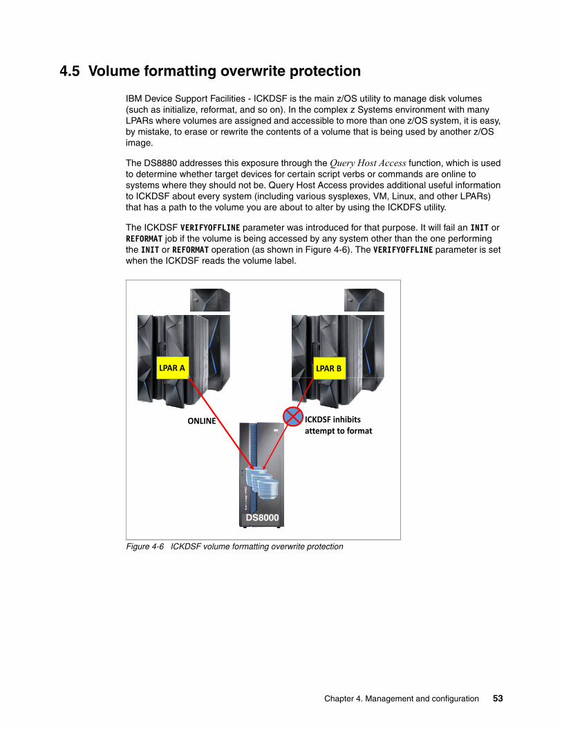
4.5 Volume formatting overwrite protection
IBM Device Support Facilities - ICKDSF is the main z/OS utility to manage disk volumes (such as initialize, reformat, and so on). In the complex z Systems environment with many LPARs where volumes are assigned and accessible to more than one z/OS system, it is easy, by mistake, to erase or rewrite the contents of a volume that is being used by another z/OS image.
The DS8880 addresses this exposure through the Query Host Access function, which is used to determine whether target devices for certain script verbs or commands are online to systems where they should not be. Query Host Access provides additional useful information to ICKDSF about every system (including various sysplexes, VM, Linux, and other LPARs) that has a path to the volume you are about to alter by using the ICKDFS utility.
The ICKDSF VERIFYOFFLINE parameter was introduced for that purpose. It will fail an INIT or REFORMAT job if the volume is being accessed by any system other than the one performing the INIT or REFORMAT operation (as shown in Figure 4-6). The VERIFYOFFLINE parameter is set when the ICKDSF reads the volume label.
Figure 4-6 ICKDSF volume formatting overwrite protection
DS8870
LPAR A LPAR B
ONLINE ICKDSF inhibits attempt to format
DS8000
Chapter 4. Management and configuration 53
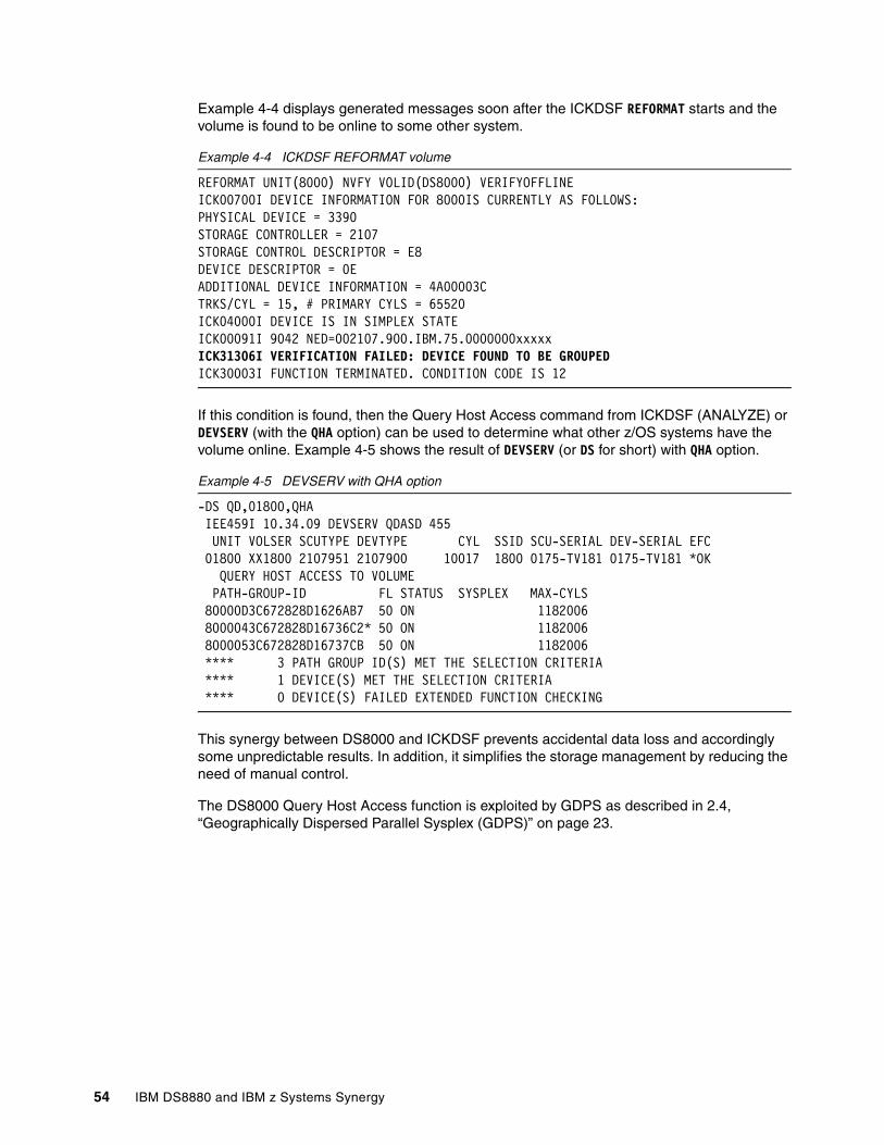
Example 4-4 displays generated messages soon after the ICKDSF REFORMAT starts and the volume is found to be online to some other system.
Example 4-4 ICKDSF REFORMAT volume
REFORMAT UNIT(8000) NVFY VOLID(DS8000) VERIFYOFFLINEICK00700I DEVICE INFORMATION FOR 8000IS CURRENTLY AS FOLLOWS:PHYSICAL DEVICE = 3390STORAGE CONTROLLER = 2107STORAGE CONTROL DESCRIPTOR = E8DEVICE DESCRIPTOR = 0EADDITIONAL DEVICE INFORMATION = 4A00003CTRKS/CYL = 15, # PRIMARY CYLS = 65520ICK04000I DEVICE IS IN SIMPLEX STATEICK00091I 9042 NED=002107.900.IBM.75.0000000xxxxxICK31306I VERIFICATION FAILED: DEVICE FOUND TO BE GROUPEDICK30003I FUNCTION TERMINATED. CONDITION CODE IS 12
If this condition is found, then the Query Host Access command from ICKDSF (ANALYZE) or DEVSERV (with the QHA option) can be used to determine what other z/OS systems have the volume online. Example 4-5 shows the result of DEVSERV (or DS for short) with QHA option.
Example 4-5 DEVSERV with QHA option
-DS QD,01800,QHA IEE459I 10.34.09 DEVSERV QDASD 455 UNIT VOLSER SCUTYPE DEVTYPE CYL SSID SCU-SERIAL DEV-SERIAL EFC 01800 XX1800 2107951 2107900 10017 1800 0175-TV181 0175-TV181 *OK QUERY HOST ACCESS TO VOLUME PATH-GROUP-ID FL STATUS SYSPLEX MAX-CYLS 80000D3C672828D1626AB7 50 ON 1182006 8000043C672828D16736C2* 50 ON 1182006 8000053C672828D16737CB 50 ON 1182006 **** 3 PATH GROUP ID(S) MET THE SELECTION CRITERIA **** 1 DEVICE(S) MET THE SELECTION CRITERIA **** 0 DEVICE(S) FAILED EXTENDED FUNCTION CHECKING
This synergy between DS8000 and ICKDSF prevents accidental data loss and accordingly some unpredictable results. In addition, it simplifies the storage management by reducing the need of manual control.
The DS8000 Query Host Access function is exploited by GDPS as described in 2.4, “Geographically Dispersed Parallel Sysplex (GDPS)” on page 23.
54 IBM DS8880 and IBM z Systems Synergy
4.6 Channel paths and control-unit-initiated reconfiguration
In the z Systems environment, normal practice is to provide multiple paths from each host to a storage system. Typically, four or eight paths are installed. The channels in each host that can access each logical control unit (LCU) in the DS8000 are defined in the hardware configuration definition (HCD) or I/O configuration data set (IOCDS) for that host. Dynamic Path Selection (DPS) allows the channel subsystem to select any available (non-busy) path to initiate an operation to the disk subsystem. Dynamic Path Reconnect (DPR) allows the DS8880 to select any available path to a host to reconnect and resume a disconnected operation; for example, to transfer data after disconnection because of a cache miss.
These functions are part of the IBM z Systems architecture and are managed by the channel subsystem on the host and the DS8000.
A physical FICON path is established when the DS8000 port sees light on the fiber; for example, a cable is plugged in to a DS8880 host adapter, a processor or the DS8880 is powered on, or a path is configured online by z/OS. Now, logical paths are established through the port between the host and some or all of the LCUs in the DS8880 are controlled by the HCD definition for that host. This configuration happens for each physical path between a z Systems host and the DS8880. Multiple system images can be in a CPU. Logical paths are established for each system image. The DS8880 then knows which paths can be used to communicate between each LCU and each host.
Control-unit initiated reconfiguration (CUIR) varies a path or paths offline to all z Systems hosts to allow service to an I/O enclosure or host adapter, then varies on the paths to all host systems when the host adapter ports are available. This function automates channel path management in z Systems environments in support of selected DS8000 service actions.
CUIR is available for the DS8880 when operated in the z/OS and IBM z/VM environments. CUIR provides automatic channel path vary on and vary off actions to minimize manual operator intervention during selected DS8880 service actions.
CUIR also allows the DS8880 to request that all attached system images set all paths that are required for a particular service action to the offline state. System images with the appropriate level of software support respond to such requests by varying off the affected paths, and either notifying the DS8880 storage system that the paths are offline or that it cannot take the paths offline. CUIR reduces manual operator intervention and the possibility of human error during maintenance actions, and reduces the time that is required for the maintenance. This function is useful in environments in which many z/OS or z/VM systems are attached to a DS8880.
4.7 CKD thin provisioning
Starting with DS8880 code levels R8.1.1 (bundles 88.11 and later), the DS8880 allows CKD volumes to be formatted as thin-provisioned extent space-efficient (ESE) volumes. These ESE volumes do physical allocation only on writes and only when another new extent is needed to satisfy the capacity of the incoming write block. The allocation granularity, and so the size of these extents, then is either 1113 cylinders, or 21 cylinders, depending on how the extent pool was formatted. Obviously, using small extents makes more sense in the context of thin provisioning.
One scenario to use such thinly provisioned volumes is, for instance, only for FlashCopy target volumes, or for Global Mirror Journal volumes, allowing them to be space-efficient while maintaining standard (thick) volume sizes for the operational source volumes. ESE volumes
Chapter 4. Management and configuration 55
that are preferably placed on 21-cylinder extent pools are the replacement for the former track-space efficient (TSE) volumes, which are no longer supported.
Another scenario is to create all volumes as ESE volumes. In PPRC relationships, this has the advantage that on initial replication, extents that are not yet allocated in a primary volume do not need to be replicated, thereby saving on bandwidth also.
Thin provisioning in general requires a tight control of the capacity that is free physically in the given extent pool, especially when doing over-provisioning. Yet these controls are there, along with respective alert thresholds and alerts that can be set.
AdvantagesThin provisioning can make storage administration easier. You can provision large volumes when you configure a new IBM DS8880. You do not have to manage different volume sizes, when you use a 3390 Model 1 size, a Model 9, or better a Model 27, and so on. You can make all volumes large and of the same size. At times, a volume or device address is required to communicate with the control unit, such as the utility device for XRC. Such a volume can include a minimum capacity. With thin provisioning, you still can use a large volume because less data is written to such a volume, its size in actual physical space remains small, and no storage capacity is wasted.
For many z/OS customers, migrating to larger volumes is a task they avoid because it involves substantial work. As a result, many customers have too many small 3390 Model 3 volumes. With thin provisioning, they can define large volumes and migrate data from other storage systems to an IBM DS8880 that is defined with thin-provisioned volumes and likely use even less space. Most migration methods facilitate copying small volumes to a larger volume. You refresh the VTOC of the volume to recognize the new size.
APARsCheck APARs for thin provisioning. The initial z/OS support was provided with the corresponding software exploitation of small programming enhancement (SPE) for z/OS V2.1 and later: APARs PI47180, OA48710, OA48723, OA48711, OA48709, OA48707, OA50453 and OA50675.
Space releaseSpace is released when a volume is deleted. Space also is released on FlashCopy target volumes when the target volume is thin-provisioned. A space release also is done on the target of a Metro Mirror or Global Copy when the relationship is established if the source and target are thin-provisioned.
Introduced with the R8.2 DS8880 code and APAR OA50675 is the ability for storage administrators to perform an extent-level space release with a new DFSMSdss SPACEREL command. It is a volume-level command to scan and release free extents from volumes back to the extent pool. The SPACEREL command can be issued for volumes or storage groups and has the following format:
SPACERelDDName(ddn)DYNam(volser,unit)STORGRP(groupname)
For more details about this topic, see IBM DS8880 Thin Provisioning, REDP-5343.
56 IBM DS8880 and IBM z Systems Synergy
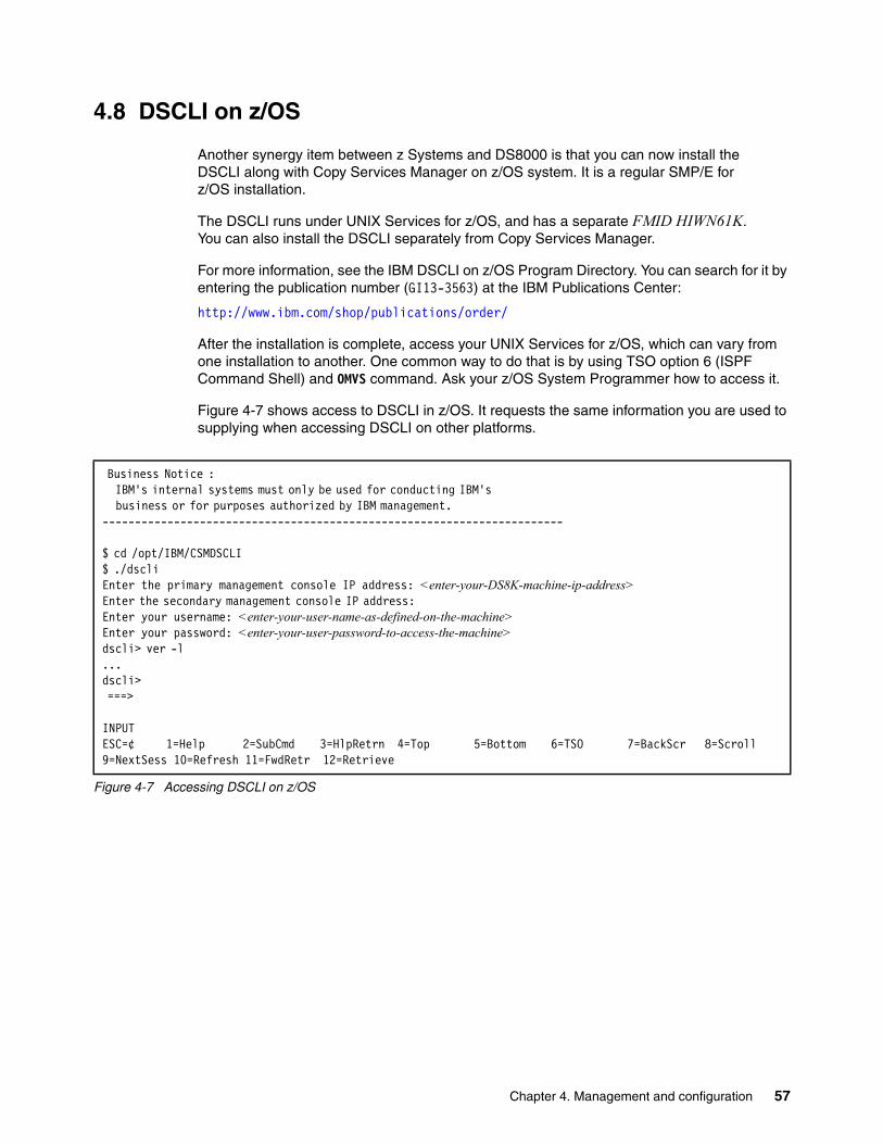
4.8 DSCLI on z/OS
Another synergy item between z Systems and DS8000 is that you can now install the DSCLI along with Copy Services Manager on z/OS system. It is a regular SMP/E for z/OS installation.
The DSCLI runs under UNIX Services for z/OS, and has a separate FMID HIWN61K. You can also install the DSCLI separately from Copy Services Manager.
For more information, see the IBM DSCLI on z/OS Program Directory. You can search for it by entering the publication number (GI13-3563) at the IBM Publications Center:
http://www.ibm.com/shop/publications/order/
After the installation is complete, access your UNIX Services for z/OS, which can vary from one installation to another. One common way to do that is by using TSO option 6 (ISPF Command Shell) and OMVS command. Ask your z/OS System Programmer how to access it.
Figure 4-7 shows access to DSCLI in z/OS. It requests the same information you are used to supplying when accessing DSCLI on other platforms.
Figure 4-7 Accessing DSCLI on z/OS
Business Notice : IBM's internal systems must only be used for conducting IBM's business or for purposes authorized by IBM management. ----------------------------------------------------------------------- $ cd /opt/IBM/CSMDSCLI $ ./dscli Enter the primary management console IP address: <enter-your-DS8K-machine-ip-address> Enter the secondary management console IP address: Enter your username: <enter-your-user-name-as-defined-on-the-machine> Enter your password: <enter-your-user-password-to-access-the-machine> dscli> ver -l ... dscli> ===> INPUTESC=¢ 1=Help 2=SubCmd 3=HlpRetrn 4=Top 5=Bottom 6=TSO 7=BackScr 8=Scroll 9=NextSess 10=Refresh 11=FwdRetr 12=Retrieve
Chapter 4. Management and configuration 57
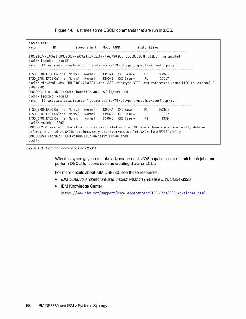
Figure 4-8 illustrates some DSCLI commands that are run in z/OS.
Figure 4-8 Common commands on DSCLI
With this synergy, you can take advantage of all z/OS capabilities to submit batch jobs and perform DSCLI functions such as creating disks or LCUs.
For more details about IBM DS8880, see these resources:
� IBM DS8880 Architecture and Implementation (Release 8.2), SG24-8323
� IBM Knowledge Center:
https://www.ibm.com/support/knowledgecenter/ST5GLJ/ds8000_kcwelcome.html
dscli> lssi Name ID Storage Unit Model WWNN State ESSNet ======================================================================================== IBM.2107-75ACA91 IBM.2107-75ACA91 IBM.2107-75ACA90 980 5005076303FFD13E Online Enabled dscli> lsckdvol -lcu EF Name ID accstate datastate configstate deviceMTM voltype orgbvols extpool cap (cyl) =========================================================================================== ITSO_EF00 EF00 Online Normal Normal 3390-A CKD Base - P1 262668 ITSO_EF01 EF01 Online Normal Normal 3390-9 CKD Base - P1 10017 dscli> mkckdvol -dev IBM.2107-75ACA91 -cap 3339 -datatype 3390 -eam rotateexts -name ITSO_#h -extpool P1 EF02-EF02 CMUC00021I mkckdvol: CKD Volume EF02 successfully created. dscli> lsckdvol -lcu EF Name ID accstate datastate configstate deviceMTM voltype orgbvols extpool cap (cyl) =========================================================================================== ITSO_EF00 EF00 Online Normal Normal 3390-A CKD Base - P1 262668 ITSO_EF01 EF01 Online Normal Normal 3390-9 CKD Base - P1 10017 ITSO_EF02 EF02 Online Normal Normal 3390-3 CKD Base - P1 3339 dscli> rmckdvol EF02 CMUC00023W rmckdvol: The alias volumes associated with a CKD base volume are automatically deleted before deletion of the CKD base volume. Are you sure you want to delete CKD volume EF02? Ýy/n¨: y CMUC00024I rmckdvol: CKD volume EF02 successfully deleted. dscli>
58 IBM DS8880 and IBM z Systems Synergy
Chapter 5. IBM z Systems and DS8880 performance
This chapter describes z Systems and DS8880 synergy features from a performance perspective and how these features contribute to enhanced resiliency of an overall mainframe storage infrastructure.
This chapter includes the following topics:
� Parallel access volume (PAV), HyperPAV, and SuperPAV� Multiple allegiance� I/O priority queuing� Modified Indirect Data Access Word (MIDAW)� Caching algorithm optimized for z Systems� z High Performance FICON for IBM z Systems (zHPF)� Easy Tier� I/O Priority Manager and WLM for z/OS integration� zHyperWrite� DS8000 Copy Services performance considerations� DS8000 and z13 and z13s I/O enhancements� zEnterprise Data Compression (zEDC)
5
© Copyright IBM Corp. 2015, 2017. All rights reserved. 59
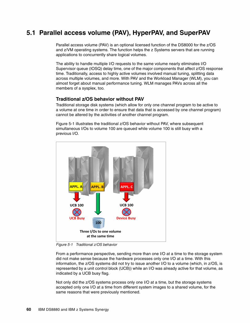
5.1 Parallel access volume (PAV), HyperPAV, and SuperPAV
Parallel access volume (PAV) is an optional licensed function of the DS8000 for the z/OS and z/VM operating systems. The function helps the z Systems servers that are running applications to concurrently share logical volumes.
The ability to handle multiple I/O requests to the same volume nearly eliminates I/O Supervisor queue (IOSQ) delay time, one of the major components that affect z/OS response time. Traditionally, access to highly active volumes involved manual tuning, splitting data across multiple volumes, and more. With PAV and the Workload Manager (WLM), you can almost forget about manual performance tuning. WLM manages PAVs across all the members of a sysplex, too.
Traditional z/OS behavior without PAVTraditional storage disk systems (which allow for only one channel program to be active to a volume at one time in order to ensure that data that is accessed by one channel program) cannot be altered by the activities of another channel program.
Figure 5-1 illustrates the traditional z/OS behavior without PAV, where subsequent simultaneous I/Os to volume 100 are queued while volume 100 is still busy with a previous I/O.
Figure 5-1 Traditional z/OS behavior
From a performance perspective, sending more than one I/O at a time to the storage system did not make sense because the hardware processes only one I/O at a time. With this information, the z/OS systems did not try to issue another I/O to a volume (which, in z/OS, is represented by a unit control block (UCB)) while an I/O was already active for that volume, as indicated by a UCB busy flag.
Not only did the z/OS systems process only one I/O at a time, but the storage systems accepted only one I/O at a time from different system images to a shared volume, for the same reasons that were previously mentioned.
DS8870
APPL. A
UCB 100
APPL. B APPL. C
100
UCB 100
UCB Busy Device Busy
Three I/Os to one volume at the same time
60 IBM DS8880 and IBM z Systems Synergy
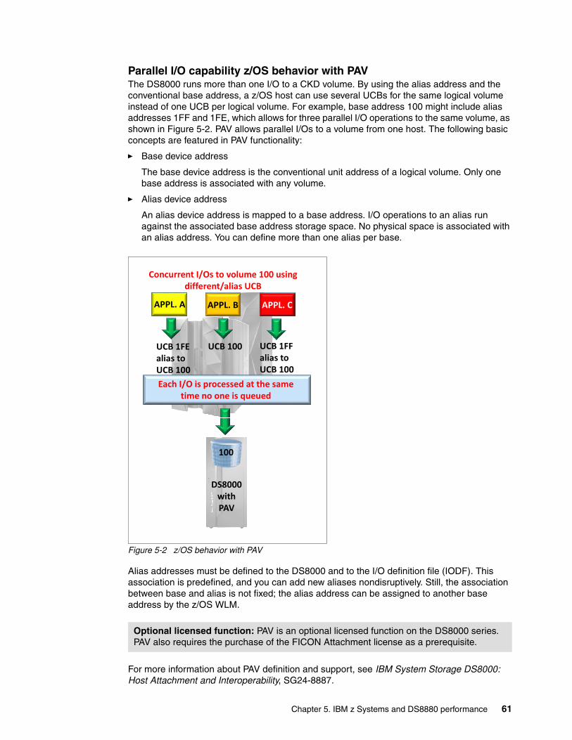
Parallel I/O capability z/OS behavior with PAVThe DS8000 runs more than one I/O to a CKD volume. By using the alias address and the conventional base address, a z/OS host can use several UCBs for the same logical volume instead of one UCB per logical volume. For example, base address 100 might include alias addresses 1FF and 1FE, which allows for three parallel I/O operations to the same volume, as shown in Figure 5-2. PAV allows parallel I/Os to a volume from one host. The following basic concepts are featured in PAV functionality:
� Base device address
The base device address is the conventional unit address of a logical volume. Only one base address is associated with any volume.
� Alias device address
An alias device address is mapped to a base address. I/O operations to an alias run against the associated base address storage space. No physical space is associated with an alias address. You can define more than one alias per base.
Figure 5-2 z/OS behavior with PAV
Alias addresses must be defined to the DS8000 and to the I/O definition file (IODF). This association is predefined, and you can add new aliases nondisruptively. Still, the association between base and alias is not fixed; the alias address can be assigned to another base address by the z/OS WLM.
For more information about PAV definition and support, see IBM System Storage DS8000: Host Attachment and Interoperability, SG24-8887.
Optional licensed function: PAV is an optional licensed function on the DS8000 series. PAV also requires the purchase of the FICON Attachment license as a prerequisite.
APPL. A
UCB 1FF alias to UCB 100
APPL. B APPL. C
100
UCB 100
Each I/O is processed at the same time no one is queued
UCB 1FE alias to UCB 100
Concurrent I/Os to volume 100 using different/alias UCB
DS8000 with PAV
Chapter 5. IBM z Systems and DS8880 performance 61
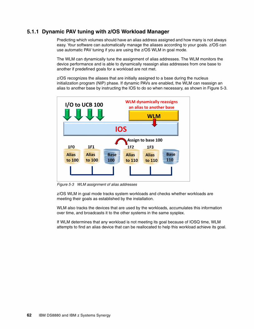
5.1.1 Dynamic PAV tuning with z/OS Workload ManagerPredicting which volumes should have an alias address assigned and how many is not always easy. Your software can automatically manage the aliases according to your goals. z/OS can use automatic PAV tuning if you are using the z/OS WLM in goal mode.
The WLM can dynamically tune the assignment of alias addresses. The WLM monitors the device performance and is able to dynamically reassign alias addresses from one base to another if predefined goals for a workload are not met.
z/OS recognizes the aliases that are initially assigned to a base during the nucleus initialization program (NIP) phase. If dynamic PAVs are enabled, the WLM can reassign an alias to another base by instructing the IOS to do so when necessary, as shown in Figure 5-3.
Figure 5-3 WLM assignment of alias addresses
z/OS WLM in goal mode tracks system workloads and checks whether workloads are meeting their goals as established by the installation.
WLM also tracks the devices that are used by the workloads, accumulates this information over time, and broadcasts it to the other systems in the same sysplex.
If WLM determines that any workload is not meeting its goal because of IOSQ time, WLM attempts to find an alias device that can be reallocated to help this workload achieve its goal.
Assign to base 100
WLM
Base 100
I/O to UCB 100
IOS
1F0
WLM dynamically reassigns an alias to another base
Alias to 100
1F1
Alias to 100
1F3
Alias to 110
1F2
Alias to 110
Base 110
62 IBM DS8880 and IBM z Systems Synergy
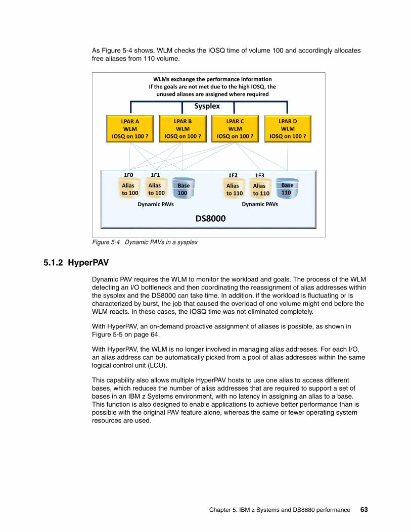
As Figure 5-4 shows, WLM checks the IOSQ time of volume 100 and accordingly allocates free aliases from 110 volume.
Figure 5-4 Dynamic PAVs in a sysplex
5.1.2 HyperPAV
Dynamic PAV requires the WLM to monitor the workload and goals. The process of the WLM detecting an I/O bottleneck and then coordinating the reassignment of alias addresses within the sysplex and the DS8000 can take time. In addition, if the workload is fluctuating or is characterized by burst, the job that caused the overload of one volume might end before the WLM reacts. In these cases, the IOSQ time was not eliminated completely.
With HyperPAV, an on-demand proactive assignment of aliases is possible, as shown in Figure 5-5 on page 64.
With HyperPAV, the WLM is no longer involved in managing alias addresses. For each I/O, an alias address can be automatically picked from a pool of alias addresses within the same logical control unit (LCU).
This capability also allows multiple HyperPAV hosts to use one alias to access different bases, which reduces the number of alias addresses that are required to support a set of bases in an IBM z Systems environment, with no latency in assigning an alias to a base. This function is also designed to enable applications to achieve better performance than is possible with the original PAV feature alone, whereas the same or fewer operating system resources are used.
Dynamic PAVs
LPAR A WLM
IOSQ on 100 ?
Base 100
Sysplex
1F0
Alias to 100
1F1
Alias to 100
1F3
Alias to 110
1F2
Alias to 110
Base 110
Dynamic PAVs
DS8000
LPAR B WLM
IOSQ on 100 ?
LPAR C WLM
IOSQ on 100 ?
LPAR D WLM
IOSQ on 100 ?
WLMs exchange the performance information If the goals are not met due to the high IOSQ, the
unused aliases are assigned where required
Chapter 5. IBM z Systems and DS8880 performance 63
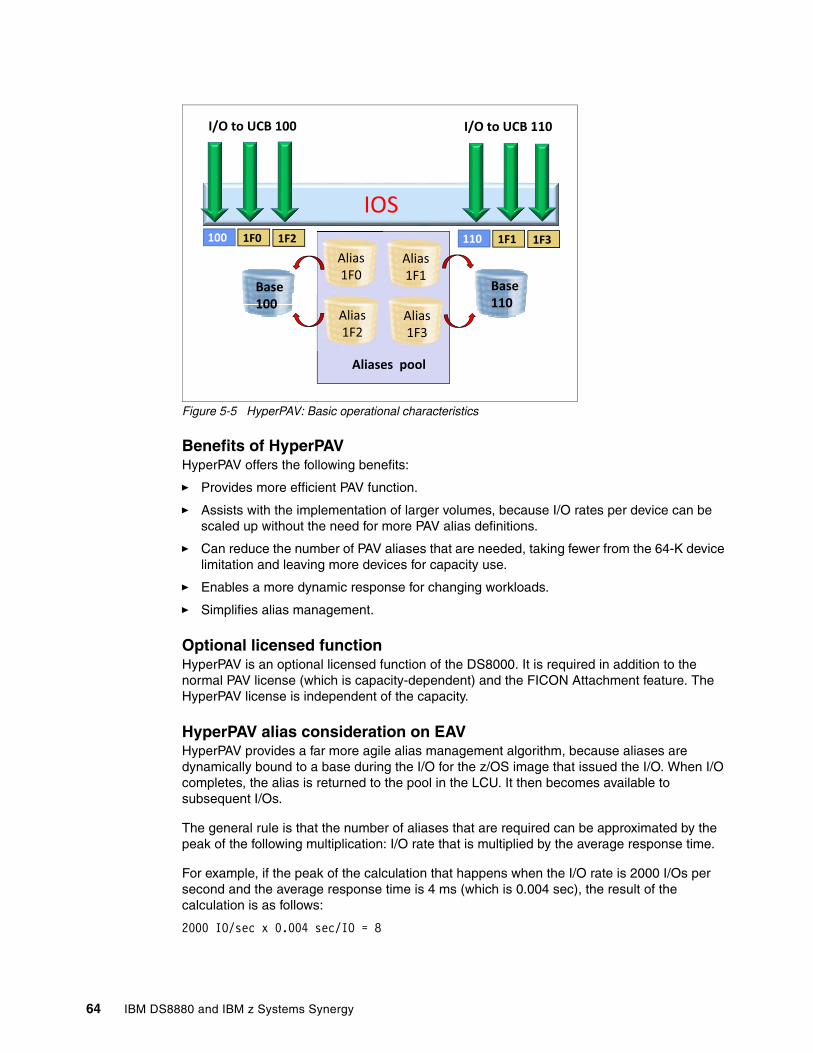
Figure 5-5 HyperPAV: Basic operational characteristics
Benefits of HyperPAVHyperPAV offers the following benefits:
� Provides more efficient PAV function.
� Assists with the implementation of larger volumes, because I/O rates per device can be scaled up without the need for more PAV alias definitions.
� Can reduce the number of PAV aliases that are needed, taking fewer from the 64-K device limitation and leaving more devices for capacity use.
� Enables a more dynamic response for changing workloads.
� Simplifies alias management.
Optional licensed functionHyperPAV is an optional licensed function of the DS8000. It is required in addition to the normal PAV license (which is capacity-dependent) and the FICON Attachment feature. The HyperPAV license is independent of the capacity.
HyperPAV alias consideration on EAVHyperPAV provides a far more agile alias management algorithm, because aliases are dynamically bound to a base during the I/O for the z/OS image that issued the I/O. When I/O completes, the alias is returned to the pool in the LCU. It then becomes available to subsequent I/Os.
The general rule is that the number of aliases that are required can be approximated by the peak of the following multiplication: I/O rate that is multiplied by the average response time.
For example, if the peak of the calculation that happens when the I/O rate is 2000 I/Os per second and the average response time is 4 ms (which is 0.004 sec), the result of the calculation is as follows:
2000 IO/sec x 0.004 sec/IO = 8
Aliases pool
Base 100
I/O to UCB 100
IOS
Alias 1F0
Base 110
Alias 1F2
Alias 1F1
Alias 1F3
I/O to UCB 110
100 1F0 1F2 110 1F1 1F3
64 IBM DS8880 and IBM z Systems Synergy
This result means that the average number of I/O operations that are running at one time for that LCU during the peak period is eight. Therefore, eight aliases should be able to handle the peak I/O rate for that LCU. However, because this calculation is based on the average during the IBM Resource Measurement Facility™ (RMF™) period, multiply the result by two to accommodate higher peaks within that RMF interval. So, in this case, the advised number of aliases is 16 (2 x 8 = 16).
A more precise approach to really know how many PAVs are needed is to look at the RMF I/O Queuing Activity LCU report. The report shows these two values:
� HyperPAV Wait Ratio: Ratio of the number of times an I/O did not start and the total number of I/O requests
� HyperPAV Maximum: Maximum number of concurrently in-use HyperPAV alias
If a value exists for the HyperPAV Wait Ratio, more PAVs are needed. If there is no waiting (no value), then the maximum is the number of PAVs needed. Those values must of course be monitored and evaluated over time, looking for peaks and comparing values for various LPARs.
Depending on the workload, there is a huge reduction in PAV-alias UCBs with HyperPAV. The combination of HyperPAV and EAV allows you to significantly reduce the constraint on the 64-K device address limit and, in turn, increase the amount of addressable storage that is available on z/OS. With multiple subchannel sets (MSS) on IBM z Systems, you have even more flexibility in device configuration. The EAV volumes are supported only on IBM z/OS V1.10 and later.
See these Redbooks publications:
� For more information about EAV specifications and considerations, see IBM System Storage DS8000: Host Attachment and Interoperability, SG24-8887.
� For more information about MSS, see Multiple Subchannel Sets: An Implementation View, REDP-4387.
HyperPAV implementation and system requirementsFor more information about support and implementation guidance, see IBM System Storage DS8000: Host Attachment and Interoperability, SG24-8887.
5.1.3 Resource Measurement Facility (RMF) reporting on PAV
RMF reports the number of exposures for each device in these reports:
� Monitor/DASD Activity report� Monitor II and Monitor III Device reports
If the device is a HyperPAV base device, the number is followed by the letter “H” (for example, 5.4H). This value is the average number of HyperPAV volumes (base and alias) in that interval. RMF reports all I/O activity against the base address, not by the individual base and associated aliases. The performance information for the base includes all base and alias I/O activity.
Chapter 5. IBM z Systems and DS8880 performance 65
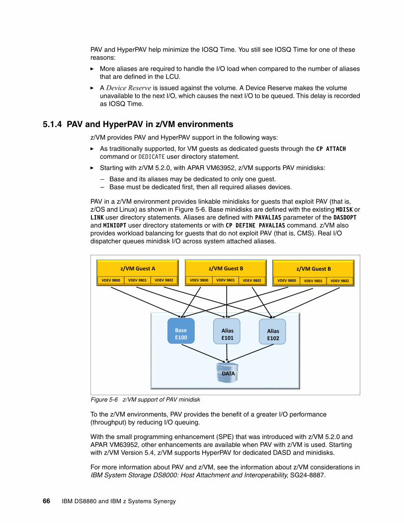
PAV and HyperPAV help minimize the IOSQ Time. You still see IOSQ Time for one of these reasons:
� More aliases are required to handle the I/O load when compared to the number of aliases that are defined in the LCU.
� A Device Reserve is issued against the volume. A Device Reserve makes the volume unavailable to the next I/O, which causes the next I/O to be queued. This delay is recorded as IOSQ Time.
5.1.4 PAV and HyperPAV in z/VM environmentsz/VM provides PAV and HyperPAV support in the following ways:
� As traditionally supported, for VM guests as dedicated guests through the CP ATTACH command or DEDICATE user directory statement.
� Starting with z/VM 5.2.0, with APAR VM63952, z/VM supports PAV minidisks:
– Base and its aliases may be dedicated to only one guest.– Base must be dedicated first, then all required aliases devices.
PAV in a z/VM environment provides linkable minidisks for guests that exploit PAV (that is, z/OS and Linux) as shown in Figure 5-6. Base minidisks are defined with the existing MDISK or LINK user directory statements. Aliases are defined with PAVALIAS parameter of the DASDOPT and MINIOPT user directory statements or with CP DEFINE PAVALIAS command. z/VM also provides workload balancing for guests that do not exploit PAV (that is, CMS). Real I/O dispatcher queues minidisk I/O across system attached aliases.
Figure 5-6 z/VM support of PAV minidisk
To the z/VM environments, PAV provides the benefit of a greater I/O performance (throughput) by reducing I/O queuing.
With the small programming enhancement (SPE) that was introduced with z/VM 5.2.0 and APAR VM63952, other enhancements are available when PAV with z/VM is used. Starting with z/VM Version 5.4, z/VM supports HyperPAV for dedicated DASD and minidisks.
For more information about PAV and z/VM, see the information about z/VM considerations in IBM System Storage DS8000: Host Attachment and Interoperability, SG24-8887.
z/VM Guest A
DATA
Base E100
Alias E101
VDEV 9800 VDEV 9801 VDEV 9802
z/VM Guest B
VDEV 9800 VDEV 9801 VDEV 9802
z/VM Guest B
VDEV 9800 VDEV 9801 VDEV 9802
Alias E102
66 IBM DS8880 and IBM z Systems Synergy
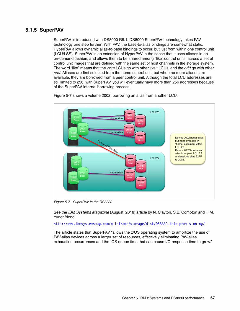
5.1.5 SuperPAV
SuperPAV is introduced with DS8000 R8.1. DS8000 SuperPAV technology takes PAV technology one step further: With PAV, the base-to-alias bindings are somewhat static. HyperPAV allows dynamic alias-to-base bindings to occur, but just from within one control unit (LCU/LSS). SuperPAV is an extension of HyperPAV in the sense that it uses aliases in an on-demand fashion, and allows them to be shared among “like” control units, across a set of control unit images that are defined with the same set of host channels in the storage system. The word “like” means that the even LCUs go with other even LCUs, and the odd go with other odd. Aliases are first selected from the home control unit, but when no more aliases are available, they are borrowed from a peer control unit. Although the total LCU addresses are still limited to 256, with SuperPAV, you will eventually have more than 256 addresses because of the SuperPAV internal borrowing process.
Figure 5-7 shows a volume 2002, borrowing an alias from another LCU.
Figure 5-7 SuperPAV in the DS8880
See the IBM Systems Magazine (August, 2016) article by N. Clayton, S.B. Compton and H.M. Yudenfriend:
http://www.ibmsystemsmag.com/mainframe/storage/disk/DS8880-thin-provisioning/
The article states that SuperPAV “allows the z/OS operating system to amortize the use of PAV-alias devices across a larger set of resources, effectively eliminating PAV-alias exhaustion occurrences and the IOS queue time that can cause I/O response time to grow.”
20FF
Alias
20FE
Alias
20FD
Alias
20FD
Alias
22FF
Alias
22FE
Alias
22FD
Alias
22FD
Alias
LCU 20
LCU 22
20FF
Alias
20FD
Alias
Home Alias
Home Alias
Home Alias
Device 2002 needs alias
but none available in
“home” alias pool within
LCU 20.
Device 2002 borrows an
alias from peer LCU 22
and assigns alias 22FF
to 2002.
2000
Base
2002
Base
2200
Base
2202
Base
2201
Base
2001
Base
Chapter 5. IBM z Systems and DS8880 performance 67
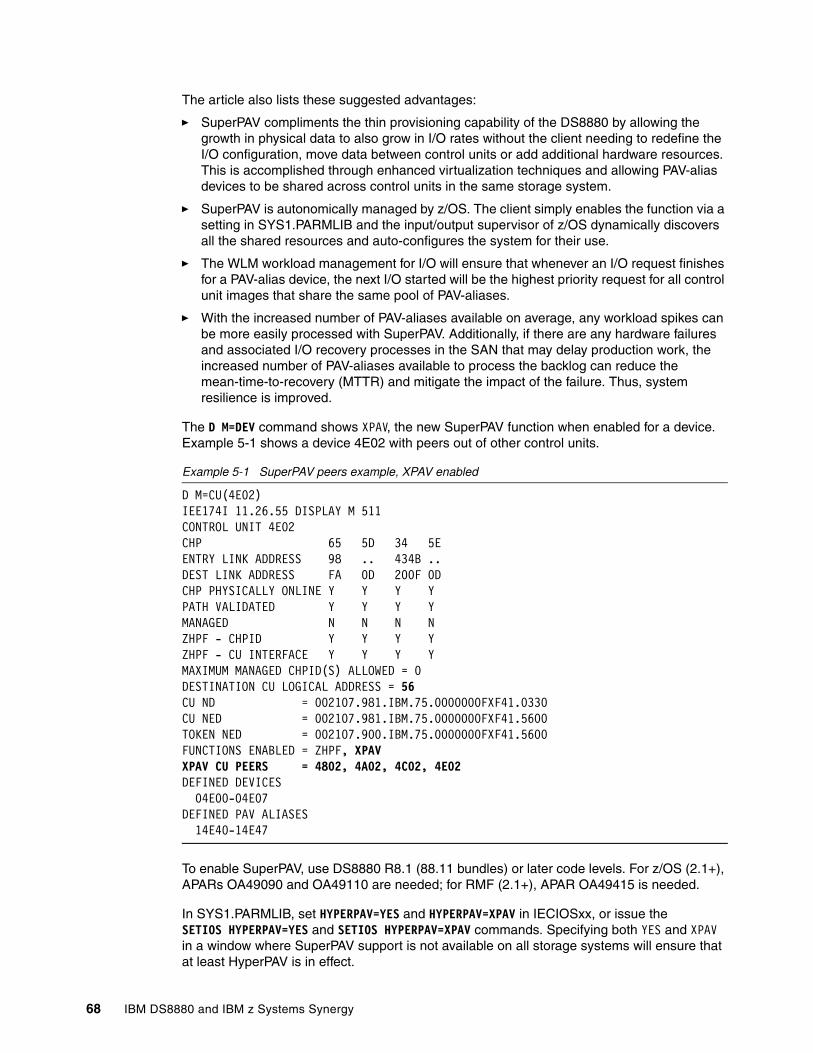
The article also lists these suggested advantages:
� SuperPAV compliments the thin provisioning capability of the DS8880 by allowing the growth in physical data to also grow in I/O rates without the client needing to redefine the I/O configuration, move data between control units or add additional hardware resources. This is accomplished through enhanced virtualization techniques and allowing PAV-alias devices to be shared across control units in the same storage system.
� SuperPAV is autonomically managed by z/OS. The client simply enables the function via a setting in SYS1.PARMLIB and the input/output supervisor of z/OS dynamically discovers all the shared resources and auto-configures the system for their use.
� The WLM workload management for I/O will ensure that whenever an I/O request finishes for a PAV-alias device, the next I/O started will be the highest priority request for all control unit images that share the same pool of PAV-aliases.
� With the increased number of PAV-aliases available on average, any workload spikes can be more easily processed with SuperPAV. Additionally, if there are any hardware failures and associated I/O recovery processes in the SAN that may delay production work, the increased number of PAV-aliases available to process the backlog can reduce the mean-time-to-recovery (MTTR) and mitigate the impact of the failure. Thus, system resilience is improved.
The D M=DEV command shows XPAV, the new SuperPAV function when enabled for a device.Example 5-1 shows a device 4E02 with peers out of other control units.
Example 5-1 SuperPAV peers example, XPAV enabled
D M=CU(4E02) IEE174I 11.26.55 DISPLAY M 511 CONTROL UNIT 4E02 CHP 65 5D 34 5E ENTRY LINK ADDRESS 98 .. 434B .. DEST LINK ADDRESS FA 0D 200F 0D CHP PHYSICALLY ONLINE Y Y Y Y PATH VALIDATED Y Y Y Y MANAGED N N N N ZHPF - CHPID Y Y Y Y ZHPF - CU INTERFACE Y Y Y Y MAXIMUM MANAGED CHPID(S) ALLOWED = 0 DESTINATION CU LOGICAL ADDRESS = 56 CU ND = 002107.981.IBM.75.0000000FXF41.0330CU NED = 002107.981.IBM.75.0000000FXF41.5600TOKEN NED = 002107.900.IBM.75.0000000FXF41.5600FUNCTIONS ENABLED = ZHPF, XPAV XPAV CU PEERS = 4802, 4A02, 4C02, 4E02 DEFINED DEVICES 04E00-04E07 DEFINED PAV ALIASES 14E40-14E47
To enable SuperPAV, use DS8880 R8.1 (88.11 bundles) or later code levels. For z/OS (2.1+), APARs OA49090 and OA49110 are needed; for RMF (2.1+), APAR OA49415 is needed.
In SYS1.PARMLIB, set HYPERPAV=YES and HYPERPAV=XPAV in IECIOSxx, or issue the SETIOS HYPERPAV=YES and SETIOS HYPERPAV=XPAV commands. Specifying both YES and XPAV in a window where SuperPAV support is not available on all storage systems will ensure that at least HyperPAV is in effect.
68 IBM DS8880 and IBM z Systems Synergy
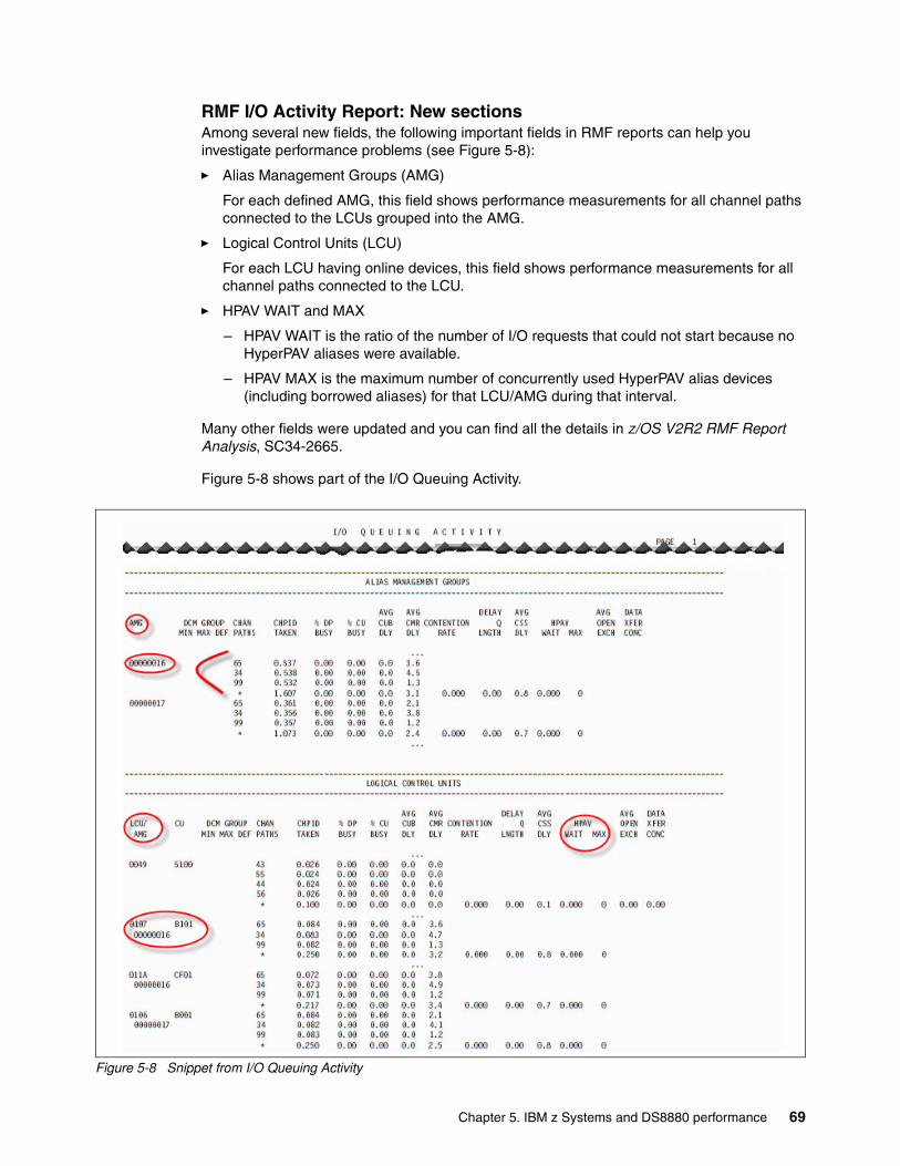
RMF I/O Activity Report: New sectionsAmong several new fields, the following important fields in RMF reports can help you investigate performance problems (see Figure 5-8):
� Alias Management Groups (AMG)
For each defined AMG, this field shows performance measurements for all channel paths connected to the LCUs grouped into the AMG.
� Logical Control Units (LCU)
For each LCU having online devices, this field shows performance measurements for all channel paths connected to the LCU.
� HPAV WAIT and MAX
– HPAV WAIT is the ratio of the number of I/O requests that could not start because no HyperPAV aliases were available.
– HPAV MAX is the maximum number of concurrently used HyperPAV alias devices (including borrowed aliases) for that LCU/AMG during that interval.
Many other fields were updated and you can find all the details in z/OS V2R2 RMF Report Analysis, SC34-2665.
Figure 5-8 shows part of the I/O Queuing Activity.
Figure 5-8 Snippet from I/O Queuing Activity
Chapter 5. IBM z Systems and DS8880 performance 69
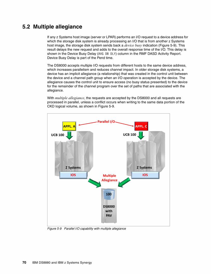
5.2 Multiple allegiance
If any z Systems host image (server or LPAR) performs an I/O request to a device address for which the storage disk system is already processing an I/O that is from another z Systems host image, the storage disk system sends back a device busy indication (Figure 5-9). This result delays the new request and adds to the overall response time of the I/O. This delay is shown in the Device Busy Delay (AVG DB DLY) column in the RMF DASD Activity Report. Device Busy Delay is part of the Pend time.
The DS8000 accepts multiple I/O requests from different hosts to the same device address, which increases parallelism and reduces channel impact. In older storage disk systems, a device has an implicit allegiance (a relationship) that was created in the control unit between the device and a channel path group when an I/O operation is accepted by the device. The allegiance causes the control unit to ensure access (no busy status presented) to the device for the remainder of the channel program over the set of paths that are associated with the allegiance.
With multiple allegiance, the requests are accepted by the DS8000 and all requests are processed in parallel, unless a conflict occurs when writing to the same data portion of the CKD logical volume, as shown in Figure 5-9.
Figure 5-9 Parallel I/O capability with multiple allegiance
APPL. A APPL. C
100
UCB 100
IOS
UCB 100
Parallel I/O
DS8000 with PAV
CCB 100
IOSMultiple Allegiance
Z Systems Z Systems
70 IBM DS8880 and IBM z Systems Synergy
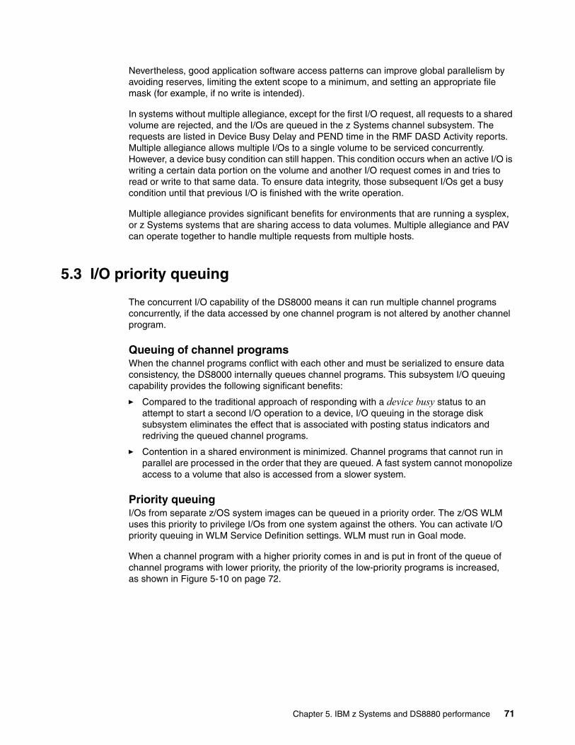
Nevertheless, good application software access patterns can improve global parallelism by avoiding reserves, limiting the extent scope to a minimum, and setting an appropriate file mask (for example, if no write is intended).
In systems without multiple allegiance, except for the first I/O request, all requests to a shared volume are rejected, and the I/Os are queued in the z Systems channel subsystem. The requests are listed in Device Busy Delay and PEND time in the RMF DASD Activity reports. Multiple allegiance allows multiple I/Os to a single volume to be serviced concurrently. However, a device busy condition can still happen. This condition occurs when an active I/O is writing a certain data portion on the volume and another I/O request comes in and tries to read or write to that same data. To ensure data integrity, those subsequent I/Os get a busy condition until that previous I/O is finished with the write operation.
Multiple allegiance provides significant benefits for environments that are running a sysplex, or z Systems systems that are sharing access to data volumes. Multiple allegiance and PAV can operate together to handle multiple requests from multiple hosts.
5.3 I/O priority queuing
The concurrent I/O capability of the DS8000 means it can run multiple channel programs concurrently, if the data accessed by one channel program is not altered by another channel program.
Queuing of channel programsWhen the channel programs conflict with each other and must be serialized to ensure data consistency, the DS8000 internally queues channel programs. This subsystem I/O queuing capability provides the following significant benefits:
� Compared to the traditional approach of responding with a device busy status to an attempt to start a second I/O operation to a device, I/O queuing in the storage disk subsystem eliminates the effect that is associated with posting status indicators and redriving the queued channel programs.
� Contention in a shared environment is minimized. Channel programs that cannot run in parallel are processed in the order that they are queued. A fast system cannot monopolize access to a volume that also is accessed from a slower system.
Priority queuingI/Os from separate z/OS system images can be queued in a priority order. The z/OS WLM uses this priority to privilege I/Os from one system against the others. You can activate I/O priority queuing in WLM Service Definition settings. WLM must run in Goal mode.
When a channel program with a higher priority comes in and is put in front of the queue of channel programs with lower priority, the priority of the low-priority programs is increased, as shown in Figure 5-10 on page 72.
Chapter 5. IBM z Systems and DS8880 performance 71
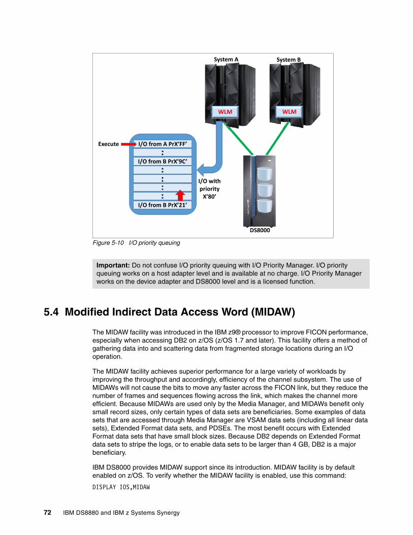
Figure 5-10 I/O priority queuing
5.4 Modified Indirect Data Access Word (MIDAW)
The MIDAW facility was introduced in the IBM z9® processor to improve FICON performance, especially when accessing DB2 on z/OS (z/OS 1.7 and later). This facility offers a method of gathering data into and scattering data from fragmented storage locations during an I/O operation.
The MIDAW facility achieves superior performance for a large variety of workloads by improving the throughput and accordingly, efficiency of the channel subsystem. The use of MIDAWs will not cause the bits to move any faster across the FICON link, but they reduce the number of frames and sequences flowing across the link, which makes the channel more efficient. Because MIDAWs are used only by the Media Manager, and MIDAWs benefit only small record sizes, only certain types of data sets are beneficiaries. Some examples of data sets that are accessed through Media Manager are VSAM data sets (including all linear data sets), Extended Format data sets, and PDSEs. The most benefit occurs with Extended Format data sets that have small block sizes. Because DB2 depends on Extended Format data sets to stripe the logs, or to enable data sets to be larger than 4 GB, DB2 is a major beneficiary.
IBM DS8000 provides MIDAW support since its introduction. MIDAW facility is by default enabled on z/OS. To verify whether the MIDAW facility is enabled, use this command:
DISPLAY IOS,MIDAW
Important: Do not confuse I/O priority queuing with I/O Priority Manager. I/O priority queuing works on a host adapter level and is available at no charge. I/O Priority Manager works on the device adapter and DS8000 level and is a licensed function.
DS8000
I/O with priority
X’80’
Execute
System A
DS8000
WLM WLM
System B
I/O from A PrX’FF’
I/O from B PrX’9C’
I/O from B PrX’21’
72 IBM DS8880 and IBM z Systems Synergy
If the facility is disabled, update the IECIOSxx member with MIDAW=YES.
For more information about advantages for DB2 with enabled MIDAW, see How does the MIDAW Facility Improve the Performance of FICON Channels Using DB2 and other workloads?, REDP-4201.
5.5 Caching algorithm optimized for z Systems
One main differentiator among available enterprise storage systems today is the internal cache and its algorithm. Cache size and its utilization efficiency is an important factor to consider when sizing the storage to meet a client’s performance requirements.
With IBM DS8880 and its powerful IBM POWER8® processors, managing large cache with small cache slots of 4 KB becomes possible. Disk systems generally divide cache into fixed size slots. A slot (sometimes known as “segment” or “cache page”) is used to hold contiguous data, so randomly read or written blocks are assigned different slots. The more random the I/Os and the smaller the block sizes, the more cache that is wasted because of large slot sizes. Therefore, the DS8880 small cache slots are the main contributing factor regarding the efficient cache utilization.
The small cache slots are served by sophisticated caching algorithms, another significant advantage of the IBM DS8000 from a performance perspective. These algorithms in conjunction with the small cache slot size, optimize cache hits and cache utilization. Cache hits are also optimized for different workloads, such as sequential workload and transaction-oriented random workload, which may be active at the same time. Therefore, the DS8880 provides excellent I/O response times.
The following caching algorithms are used in the DS8880 systems:
� Sequential Prefetching in Adaptive Replacement Cache (SARC)
The SARC algorithm was developed by IBM Storage Development in partnership with IBM Research. It is a self-tuning, self-optimizing solution for a wide range of workloads with a varying mix of sequential and random I/O streams. SARC is inspired by the Adaptive Replacement Cache (ARC) algorithm and inherits many features of it.
SARC attempts to determine the following cache characteristics:
– When and which data is copied into the cache.– Which data is evicted when the cache becomes full. – How the algorithm dynamically adapts to different workloads.
The decision to copy data into the DS8880 cache can be triggered from these policies:
– Demand paging
Eight disk blocks (a 4 K cache page) are brought in only on a cache miss. Demand paging is always active for all volumes and ensures that I/O patterns with some locality discover at least recently used data in the cache.
– Prefetching
Data is copied into the cache speculatively even before it is requested. To prefetch, a prediction of likely data accesses is needed. Because effective, sophisticated prediction schemes need an extensive history of page accesses (which is not feasible in real systems), SARC uses prefetching for sequential workloads. Sequential access patterns naturally arise in many z Systems workloads, such as database scans, copy, backup, and recovery. The goal of sequential prefetching is to detect sequential access and effectively prefetch the likely cache data to minimize cache misses.
Chapter 5. IBM z Systems and DS8880 performance 73
� Adaptive multi-stream prefetching (AMP)
In DS8880, adaptive multi-stream prefetching (AMP), an algorithm that was developed by IBM Research, manages the sequential workload. AMP is an autonomic, workload-responsive, self-optimizing prefetching technology that adapts the amount of prefetch and the timing of prefetch on a per-application basis to maximize the performance of the system. The AMP algorithm solves the following problems that plague most other prefetching algorithms:
– Prefetch wastage occurs when prefetched data is evicted from the cache before it can be used.
– Cache pollution occurs when less useful data is prefetched instead of more useful data.
By wisely choosing the prefetching parameters, AMP provides optimal sequential read performance and maximizes the aggregate sequential read throughput of the system. The timing of the prefetches is also continuously adapted for each stream to avoid misses and any cache pollution. SARC and AMP play complementary roles.
� Intelligent Write Caching (IWC)
Another cache algorithm, referred to as Intelligent Write Caching (IWC), is implemented in the DS8000 series. IWC improves performance through better write cache management and a better destaging order of writes. This algorithm is a combination of CLOCK, a predominantly read cache algorithm, and CSCAN, an efficient write cache algorithm. From this combination, IBM produced a powerful and widely applicable write cache algorithm.
� Adaptive List Prefetch (ALP)
ALP enables prefetch of a list of non-sequential tracks, providing improved performance for DB2 workloads.
z Systems workloads, in particular z/OS applications, such as DB2, have been modified to provide various hints to the DS8880 disk storage system on sequential processing in addition to database I/O operations. Optimization of what data is in DS8880 cache at any point in time enables clients to fully optimize the use of existing cache by significantly improving cache hits and I/O response time.
For more information about DS8000 cache algorithms, see IBM DS8880 Architecture and Implementation (Release 8.2), SG24-8323.
74 IBM DS8880 and IBM z Systems Synergy
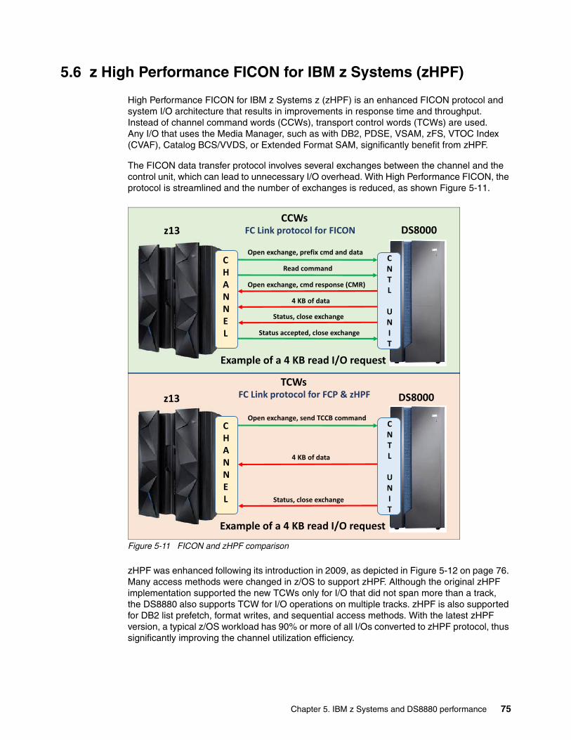
5.6 z High Performance FICON for IBM z Systems (zHPF)
High Performance FICON for IBM z Systems z (zHPF) is an enhanced FICON protocol and system I/O architecture that results in improvements in response time and throughput. Instead of channel command words (CCWs), transport control words (TCWs) are used. Any I/O that uses the Media Manager, such as with DB2, PDSE, VSAM, zFS, VTOC Index (CVAF), Catalog BCS/VVDS, or Extended Format SAM, significantly benefit from zHPF.
The FICON data transfer protocol involves several exchanges between the channel and the control unit, which can lead to unnecessary I/O overhead. With High Performance FICON, the protocol is streamlined and the number of exchanges is reduced, as shown Figure 5-11.
Figure 5-11 FICON and zHPF comparison
zHPF was enhanced following its introduction in 2009, as depicted in Figure 5-12 on page 76. Many access methods were changed in z/OS to support zHPF. Although the original zHPF implementation supported the new TCWs only for I/O that did not span more than a track, the DS8880 also supports TCW for I/O operations on multiple tracks. zHPF is also supported for DB2 list prefetch, format writes, and sequential access methods. With the latest zHPF version, a typical z/OS workload has 90% or more of all I/Os converted to zHPF protocol, thus significantly improving the channel utilization efficiency.
DS8000
CHANNEL
CNTL
UNIT
DS8000z13
Open exchange, prefix cmd and data
Read command
Open exchange, cmd response (CMR)
4 KB of data
Status, close exchange
Status accepted, close exchange
Example of a 4 KB read I/O request
CHANNEL
CNTL
UNIT
DS8000z13
Open exchange, send TCCB command
Status, close exchange
Example of a 4 KB read I/O request
CCWs
4 KB of data
FC Link protocol for FICON
TCWsFC Link protocol for FCP & zHPF
Chapter 5. IBM z Systems and DS8880 performance 75
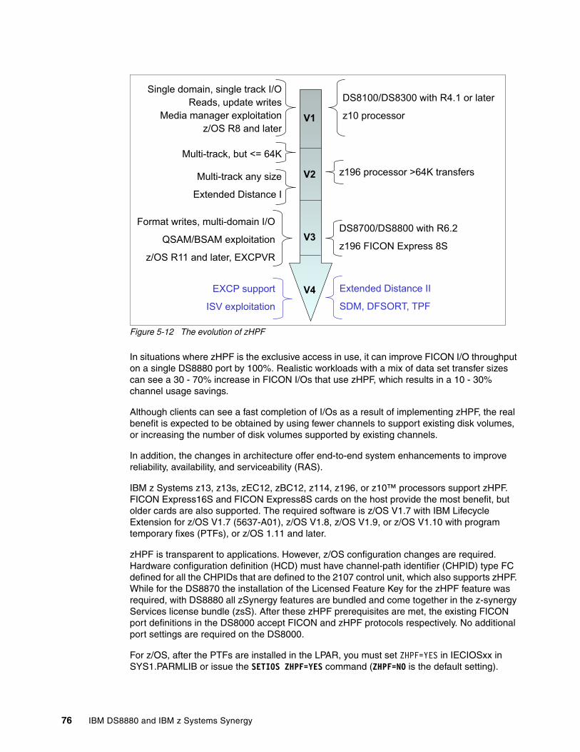
Figure 5-12 The evolution of zHPF
In situations where zHPF is the exclusive access in use, it can improve FICON I/O throughput on a single DS8880 port by 100%. Realistic workloads with a mix of data set transfer sizes can see a 30 - 70% increase in FICON I/Os that use zHPF, which results in a 10 - 30% channel usage savings.
Although clients can see a fast completion of I/Os as a result of implementing zHPF, the real benefit is expected to be obtained by using fewer channels to support existing disk volumes, or increasing the number of disk volumes supported by existing channels.
In addition, the changes in architecture offer end-to-end system enhancements to improve reliability, availability, and serviceability (RAS).
IBM z Systems z13, z13s, zEC12, zBC12, z114, z196, or z10™ processors support zHPF. FICON Express16S and FICON Express8S cards on the host provide the most benefit, but older cards are also supported. The required software is z/OS V1.7 with IBM Lifecycle Extension for z/OS V1.7 (5637-A01), z/OS V1.8, z/OS V1.9, or z/OS V1.10 with program temporary fixes (PTFs), or z/OS 1.11 and later.
zHPF is transparent to applications. However, z/OS configuration changes are required. Hardware configuration definition (HCD) must have channel-path identifier (CHPID) type FC defined for all the CHPIDs that are defined to the 2107 control unit, which also supports zHPF. While for the DS8870 the installation of the Licensed Feature Key for the zHPF feature was required, with DS8880 all zSynergy features are bundled and come together in the z-synergy Services license bundle (zsS). After these zHPF prerequisites are met, the existing FICON port definitions in the DS8000 accept FICON and zHPF protocols respectively. No additional port settings are required on the DS8000.
For z/OS, after the PTFs are installed in the LPAR, you must set ZHPF=YES in IECIOSxx in SYS1.PARMLIB or issue the SETIOS ZHPF=YES command (ZHPF=NO is the default setting).
Extended Distance II
SDM, DFSORT, TPF
EXCP support
ISV exploitation
V4
V1
DS8100/DS8300 with R4.1 or later
z10 processor
Format writes, multi-domain I/O
QSAM/BSAM exploitation
z/OS R11 and later, EXCPVR
Multi-track, but <= 64K
Multi-track any size
Extended Distance I
z196 processor >64K transfers
Single domain, single track I/O
Reads, update writes
Media manager exploitation
z/OS R8 and later
DS8700/DS8800 with R6.2
z196 FICON Express 8S
V2
V3
76 IBM DS8880 and IBM z Systems Synergy
To use zHPF for queried sequential access method (QSAM), basic sequential access method (BSAM), and basic partitioned access method (BPAM), you might need to enable it. It can be dynamically enabled by SETSMS or by the entry SAM_USE_HPF(YES | NO) in IGDSMSxx parmlib member. The default for z/OS 1.13 and later is YES; the default for z/OS 1.11 and 1.12 is NO.
5.6.1 DB2 enhancements with zHPF
In 2011, the zHPF with the DS8000 microcode delivered significant performance improvements for DB2. Today, all DB2 I/Os, including format writes and list prefetches are eligible for zHPF. In addition to it, DB2 can benefit from the DS8880 caching algorithm known as List Prefetch Optimizer thus providing even better performance. Although the objective of zHPF list prefetch is to reduce the I/O connect time, the objective of List Prefetch Optimizer is to reduce disconnect time.
DB2 typically does a maximum of two parallel list prefetch I/Os. With List Prefetch, zHPF sends a list of tracks in a Locate Record command followed by several read commands, allowing many parallel retrievals from disk. Furthermore, the Locate Record command now sends a list of non-contiguous records to prefetch, which increases the cache-hit rate for subsequent read commands.
Depending on the hardware configuration (FICON Express cards 4, 8, and 16 Gb) and DB2 version, performance can vary. As DB2 10 and later fully exploits zHPF along with the FICON Express 8S/16S on z Systems and DS8000, the following DB2 functions are improved:
� DB2 queries � Table scans� Index-to-data access, especially when the index cluster ratio is not high � Index scans, especially when the index is disorganized� Reads of a large fragmented objects (LOBs)� New extent allocation during inserts� DB2 REORG� Sequential reads � Writes to the shadow objects� Reads from a non-partitioned index� Log applies� DB2 LOAD and REBUILD� DB2 Incremental COPY� RECOVER and RESTORE� DB2 RUNSTATS table sampling
DB2 for z/OS and DS8000 zHPF synergy provides significant throughput gains in many areas resulting in reduced transaction response time and batch windows.
For more information about DB2 and List Prefetch Optimizer, see DB2 for z/OS and List Prefetch Optimizer, REDP-4862.
DB2 Castout AcceleratorIn DB2, a castout refers to the process of writing pages from the group buffer pool to disk. DB2 writes long chains that typically contain multiple locate record domains. Traditionally, each I/O in the chain is synchronized individually, whereas DB2 requires that only the updates are written in order. With DS8880 (bundles 88.11.25.0 and later, required), the Media Manager is enhanced to signal to the DS8000 that a single locate record domain exists, even though multiple embedded locate records exist. The entire I/O chain is treated as though this is a single locate record domain.
Chapter 5. IBM z Systems and DS8880 performance 77
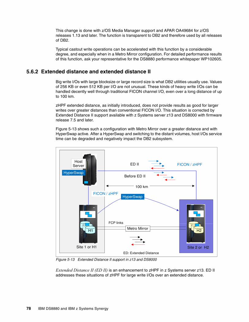
This change is done with z/OS Media Manager support and APAR OA49684 for z/OS releases 1.13 and later. The function is transparent to DB2 and therefore used by all releases of DB2.
Typical castout write operations can be accelerated with this function by a considerable degree, and especially when in a Metro Mirror configuration. For detailed performance results of this function, ask your representative for the DS8880 performance whitepaper WP102605.
5.6.2 Extended distance and extended distance II
Big write I/Os with large blocksize or large record size is what DB2 utilities usually use. Values of 256 KB or even 512 KB per I/O are not unusual. These kinds of heavy write I/Os can be handled decently well through traditional FICON channel I/O, even over a long distance of up to 100 km.
zHPF extended distance, as initially introduced, does not provide results as good for larger writes over greater distances than conventional FICON I/O. This situation is corrected by Extended Distance II support available with z Systems server z13 and DS8000 with firmware release 7.5 and later.
Figure 5-13 shows such a configuration with Metro Mirror over a greater distance and with HyperSwap active. After a HyperSwap and switching to the distant volumes, host I/Os service time can be degraded and negatively impact the DB2 subsystem.
Figure 5-13 Extended Distance II support in z13 and DS8000
Extended Distance II (ED II) is an enhancement to zHPF in z Systems server z13. ED II addresses these situations of zHPF for large write I/Os over an extended distance.
HostServer
HyperSwap
FICON / zHPF
Before ED II
ED II
FCP links
FICON / zHPF
100 km
HyperSwap
H1
Site 1 or H1
H2
Site 2 or H2
FCP links
Metro Mirror
ED: Extended Distance
78 IBM DS8880 and IBM z Systems Synergy
Similar considerations applied to Metro Mirror over Fibre Channel Protocol (FCP). To allow for increased distances of up to 300 km, Metro Mirror and its variations introduced the concept of pre-deposit writes which reduce the number of round trips of standard FCP I/Os to a single round trip.
Although zHPF Extended Distance (ED I) already uses the concept of pre-deposit writes, the benefits are limited to writes that are less than 64 KB. zHPF Extended Distance II goes beyond the capabilities of the FCP by allowing the channel to burst up to the whole write data length for an operation.
zHPF Extended Distance II improves large write I/O performance over longer distances for z Systems server z13 to DS8000 with firmware release 7.5 and later, reinforcing again the synergy between z Systems server z13/z13s and DS8880.
5.6.3 Enhanced FICON Information Unit (IU) pacing
The Information Unit (IU) pacing credit is the maximum number of IUs that a channel sends on a FICON exchange until it receives a command-response (CMR) IU, and that will allow the next send.
FICON standard default for IU pacing credits is 16. At extended distances and greater speed links, this limitation will cause relative latency for programs.
Enhanced IU pacing, available with DS8000 Release 8.2 and later, uses the persistent pacing feature to change the operating pacing credit to 64. Certain channel programs can see the latency reduced by nearly 4 times:
� CCW chains that contain more than 16 commands� DB2 log writes in GDPS multi-site workload environments
Enhanced IU pacing also benefit the FICON write performance of large writes at long distances and also the zGM (XRC) initial copy performance.
This feature applies only to 16G Fibre Channel (16GFC) Host Bus Adapters.
z/OS Global Mirror copy timesThis component also benefits from the persistent IU pacing as it allows more CCWs in the chain.
On the system data mover (SDM), the TracksPerRead parameter is not limited to 15 although it is documented as such. If the necessary resources to exploit the enhanced IU pacing are in place, a better value for TracksPerRead is 61. Certainly, those improvements will rely on the network until it can keep up. Results can vary depending on your network.
IBM Knowledge Center has more information:
https://ibm.biz/BdshcA
Chapter 5. IBM z Systems and DS8880 performance 79
5.7 Easy Tier
DS8000 Easy Tier technology is designed to enhance performance and balance workloads across different disk tiers. It enables the system, automatically and without disruption to applications, to relocate data (at the extent level) across up to three storage tiers. Having the right data on the right tier to provide a remarkable quality of service (performance and cost) to a client’s data is the main Easy Tier goal. Among z Systems clients, 10% of T0 drives (Flash/SSD) managing 90% of the I/Os is common. To be able to move extents, some free space or free extents must be available in an extent pool. For more information about space for Easy Tier, see “Space for Easy Tier” in IBM DS8880 Architecture and Implementation (Release 8.2), SG24-8323.
Easy Tier I/O workload monitoring collects I/O statistics from the physical back end, which means the back-end I/O activity on the DS8000 rank level. The system monitors the stage and destage activity of each extent that is allocated to a logical volume in the extent pool and calculates a temperature (a measure based on I/O activity) metric for each extent, also referred to as a heat map.
5.7.1 Easy Tier Application
Over time, new and improved Easy Tier functions are developed to integrate client applications with an Easy Tier algorithm, also known as Easy Tier Application. The architecture allows z Systems applications to communicate performance requirements for optimal data set placement, by communicating application performance information (hints) to the Easy Tier Application API. The application hint sets the intent, and Easy Tier moves the data set extents to the correct tier.
Figure 5-14 on page 81 shows details of the Easy Tier architecture for z Systems applications that provide data placement hints to the Easy Tier API (by using DFSMS). Currently, this is limited to DB2 for z/OS only. IBM DB2 for z/OS uses specific DFSMS functions to communicate directive data placements to Easy Tier.
80 IBM DS8880 and IBM z Systems Synergy
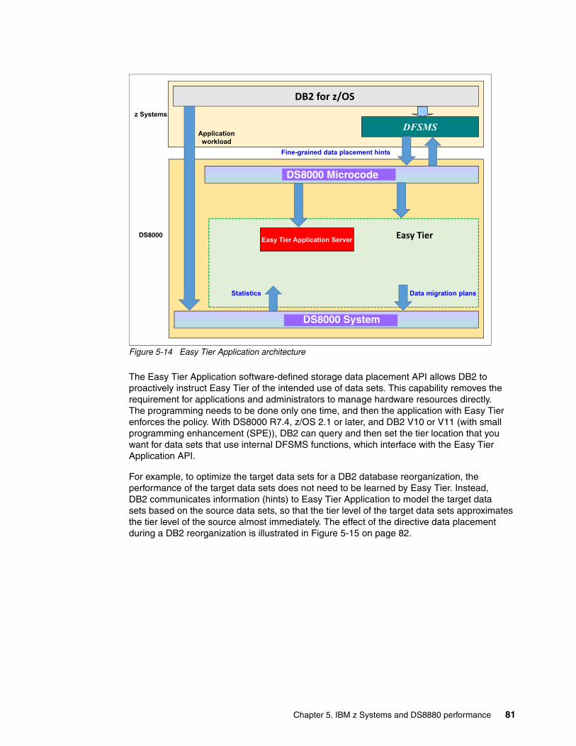
Figure 5-14 Easy Tier Application architecture
The Easy Tier Application software-defined storage data placement API allows DB2 to proactively instruct Easy Tier of the intended use of data sets. This capability removes the requirement for applications and administrators to manage hardware resources directly. The programming needs to be done only one time, and then the application with Easy Tier enforces the policy. With DS8000 R7.4, z/OS 2.1 or later, and DB2 V10 or V11 (with small programming enhancement (SPE)), DB2 can query and then set the tier location that you want for data sets that use internal DFSMS functions, which interface with the Easy Tier Application API.
For example, to optimize the target data sets for a DB2 database reorganization, the performance of the target data sets does not need to be learned by Easy Tier. Instead, DB2 communicates information (hints) to Easy Tier Application to model the target data sets based on the source data sets, so that the tier level of the target data sets approximates the tier level of the source almost immediately. The effect of the directive data placement during a DB2 reorganization is illustrated in Figure 5-15 on page 82.
DS8870 System
Easy Tier Application Server
z Systems
Applicationworkload
Statistics Data migration plans
Fine-grained data placement hints
DS8870 Microcode
DFSMS
DS8870 Easy Tier
DB2 for z/OS
DS8000
DS8000 Microcode
DS8000 System
Chapter 5. IBM z Systems and DS8880 performance 81
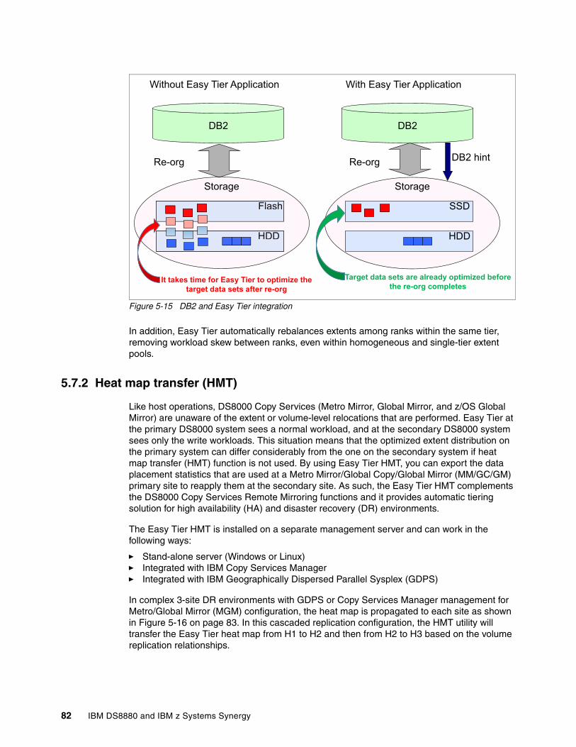
Figure 5-15 DB2 and Easy Tier integration
In addition, Easy Tier automatically rebalances extents among ranks within the same tier, removing workload skew between ranks, even within homogeneous and single-tier extent pools.
5.7.2 Heat map transfer (HMT)
Like host operations, DS8000 Copy Services (Metro Mirror, Global Mirror, and z/OS Global Mirror) are unaware of the extent or volume-level relocations that are performed. Easy Tier at the primary DS8000 system sees a normal workload, and at the secondary DS8000 system sees only the write workloads. This situation means that the optimized extent distribution on the primary system can differ considerably from the one on the secondary system if heat map transfer (HMT) function is not used. By using Easy Tier HMT, you can export the data placement statistics that are used at a Metro Mirror/Global Copy/Global Mirror (MM/GC/GM) primary site to reapply them at the secondary site. As such, the Easy Tier HMT complements the DS8000 Copy Services Remote Mirroring functions and it provides automatic tiering solution for high availability (HA) and disaster recovery (DR) environments.
The Easy Tier HMT is installed on a separate management server and can work in the following ways:
� Stand-alone server (Windows or Linux)� Integrated with IBM Copy Services Manager � Integrated with IBM Geographically Dispersed Parallel Sysplex (GDPS)
In complex 3-site DR environments with GDPS or Copy Services Manager management for Metro/Global Mirror (MGM) configuration, the heat map is propagated to each site as shown in Figure 5-16 on page 83. In this cascaded replication configuration, the HMT utility will transfer the Easy Tier heat map from H1 to H2 and then from H2 to H3 based on the volume replication relationships.
HDD
Flash
DB2
Re-org
DB2
Storage
SSD
HDD
Re-orgDB2 hint
Without Easy Tier Application With Easy Tier Application
It takes time for Easy Tier to optimize the target data sets after re-org
Target data sets are already optimized before the re-org completes
HDD
Flash
Storage
82 IBM DS8880 and IBM z Systems Synergy
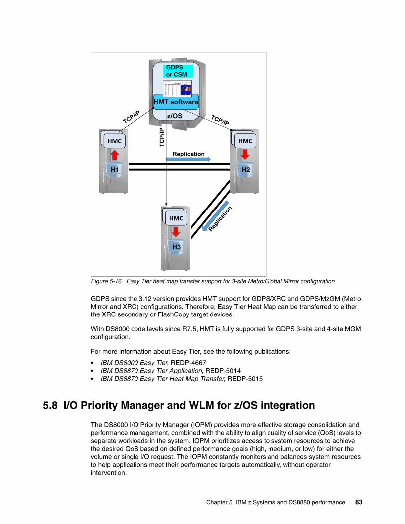
Figure 5-16 Easy Tier heat map transfer support for 3-site Metro/Global Mirror configuration
GDPS since the 3.12 version provides HMT support for GDPS/XRC and GDPS/MzGM (Metro Mirror and XRC) configurations. Therefore, Easy Tier Heat Map can be transferred to either the XRC secondary or FlashCopy target devices.
With DS8000 code levels since R7.5, HMT is fully supported for GDPS 3-site and 4-site MGM configuration.
For more information about Easy Tier, see the following publications:
� IBM DS8000 Easy Tier, REDP-4667� IBM DS8870 Easy Tier Application, REDP-5014� IBM DS8870 Easy Tier Heat Map Transfer, REDP-5015
5.8 I/O Priority Manager and WLM for z/OS integration
The DS8000 I/O Priority Manager (IOPM) provides more effective storage consolidation and performance management, combined with the ability to align quality of service (QoS) levels to separate workloads in the system. IOPM prioritizes access to system resources to achieve the desired QoS based on defined performance goals (high, medium, or low) for either the volume or single I/O request. The IOPM constantly monitors and balances system resources to help applications meet their performance targets automatically, without operator intervention.
H1
Replication
z/OS
HMT software
HMCHMC
H2
HMCHMC
H3
HMCHMC
GDPS or TPC-R
TCP/
IP
GDPSor CSM
Chapter 5. IBM z Systems and DS8880 performance 83
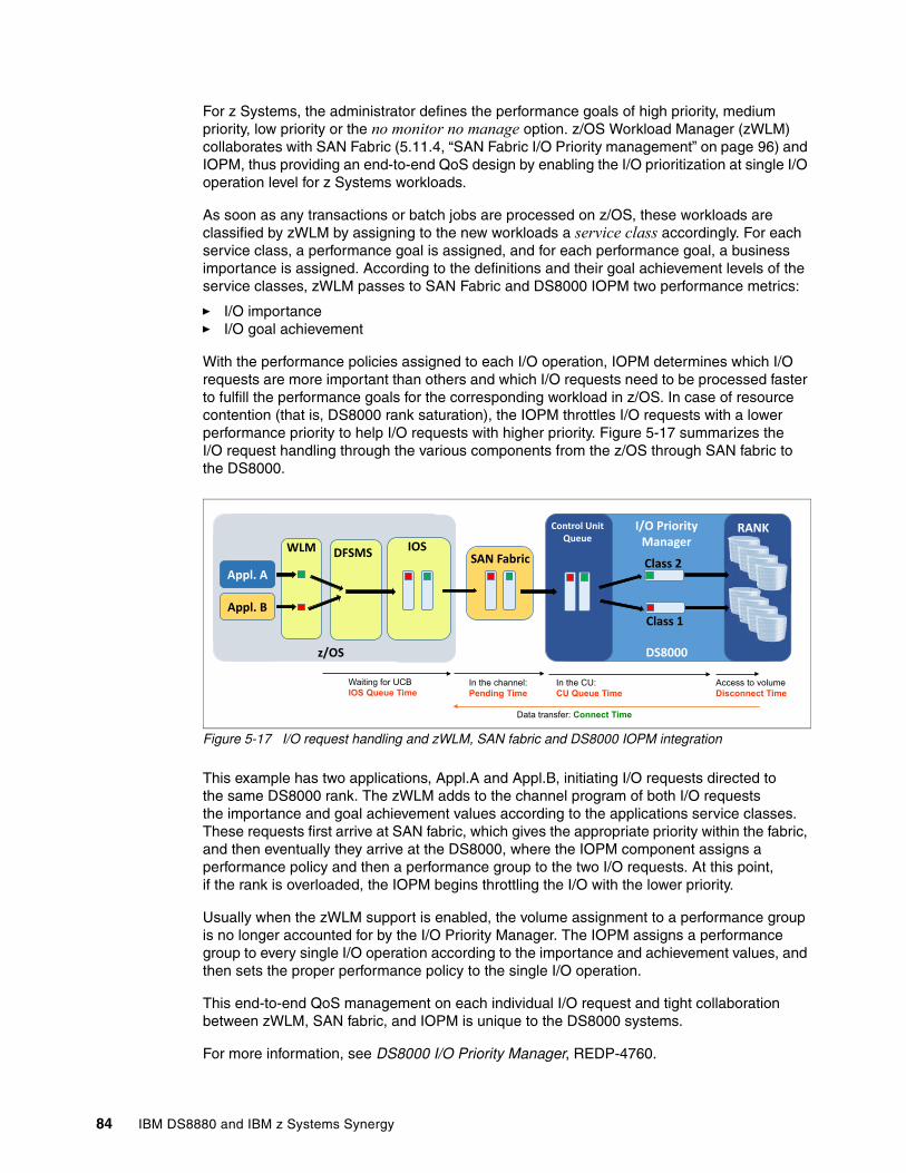
For z Systems, the administrator defines the performance goals of high priority, medium priority, low priority or the no monitor no manage option. z/OS Workload Manager (zWLM) collaborates with SAN Fabric (5.11.4, “SAN Fabric I/O Priority management” on page 96) and IOPM, thus providing an end-to-end QoS design by enabling the I/O prioritization at single I/O operation level for z Systems workloads.
As soon as any transactions or batch jobs are processed on z/OS, these workloads are classified by zWLM by assigning to the new workloads a service class accordingly. For each service class, a performance goal is assigned, and for each performance goal, a business importance is assigned. According to the definitions and their goal achievement levels of the service classes, zWLM passes to SAN Fabric and DS8000 IOPM two performance metrics:
� I/O importance� I/O goal achievement
With the performance policies assigned to each I/O operation, IOPM determines which I/O requests are more important than others and which I/O requests need to be processed faster to fulfill the performance goals for the corresponding workload in z/OS. In case of resource contention (that is, DS8000 rank saturation), the IOPM throttles I/O requests with a lower performance priority to help I/O requests with higher priority. Figure 5-17 summarizes the I/O request handling through the various components from the z/OS through SAN fabric to the DS8000.
Figure 5-17 I/O request handling and zWLM, SAN fabric and DS8000 IOPM integration
This example has two applications, Appl.A and Appl.B, initiating I/O requests directed to the same DS8000 rank. The zWLM adds to the channel program of both I/O requests the importance and goal achievement values according to the applications service classes. These requests first arrive at SAN fabric, which gives the appropriate priority within the fabric, and then eventually they arrive at the DS8000, where the IOPM component assigns a performance policy and then a performance group to the two I/O requests. At this point, if the rank is overloaded, the IOPM begins throttling the I/O with the lower priority.
Usually when the zWLM support is enabled, the volume assignment to a performance group is no longer accounted for by the I/O Priority Manager. The IOPM assigns a performance group to every single I/O operation according to the importance and achievement values, and then sets the proper performance policy to the single I/O operation.
This end-to-end QoS management on each individual I/O request and tight collaboration between zWLM, SAN fabric, and IOPM is unique to the DS8000 systems.
For more information, see DS8000 I/O Priority Manager, REDP-4760.
DS8000
Waiting for UCB
IOS Queue TimeIn the channel:
Pending TimeAccess to volume
Disconnect Time
Data transfer: Connect Time
In the CU:
CU Queue Time
WLMSAN Fabric
RANKControl Unit Queue
I/O Priority Manager
Class 2
Class 1
DS8000
Appl. A
Appl. B
DFSMS IOS
z/OS
84 IBM DS8880 and IBM z Systems Synergy
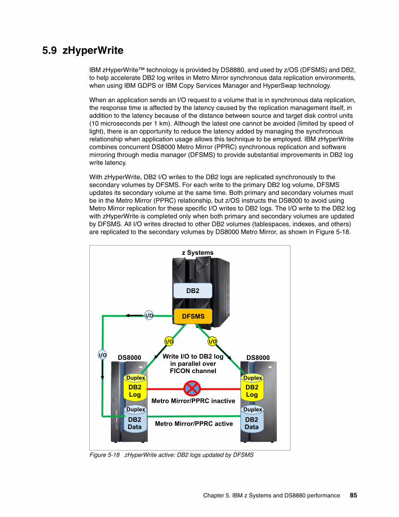
5.9 zHyperWrite
IBM zHyperWrite™ technology is provided by DS8880, and used by z/OS (DFSMS) and DB2, to help accelerate DB2 log writes in Metro Mirror synchronous data replication environments, when using IBM GDPS or IBM Copy Services Manager and HyperSwap technology.
When an application sends an I/O request to a volume that is in synchronous data replication, the response time is affected by the latency caused by the replication management itself, in addition to the latency because of the distance between source and target disk control units (10 microseconds per 1 km). Although the latest one cannot be avoided (limited by speed of light), there is an opportunity to reduce the latency added by managing the synchronous relationship when application usage allows this technique to be employed. IBM zHyperWrite combines concurrent DS8000 Metro Mirror (PPRC) synchronous replication and software mirroring through media manager (DFSMS) to provide substantial improvements in DB2 log write latency.
With zHyperWrite, DB2 I/O writes to the DB2 logs are replicated synchronously to the secondary volumes by DFSMS. For each write to the primary DB2 log volume, DFSMS updates its secondary volume at the same time. Both primary and secondary volumes must be in the Metro Mirror (PPRC) relationship, but z/OS instructs the DS8000 to avoid using Metro Mirror replication for these specific I/O writes to DB2 logs. The I/O write to the DB2 log with zHyperWrite is completed only when both primary and secondary volumes are updated by DFSMS. All I/O writes directed to other DB2 volumes (tablespaces, indexes, and others) are replicated to the secondary volumes by DS8000 Metro Mirror, as shown in Figure 5-18.
Figure 5-18 zHyperWrite active: DB2 logs updated by DFSMS
DS8000
DB2 Log
DB2
Metro Mirror/PPRC active
DFSMS
Write I/O to DB2 log in parallel over FICON channel
Metro Mirror/PPRC inactive
I/O
Duplex
z Systems
DS8000 DS8000
DB2 Data
Duplex
DB2 Log
Duplex
DB2 Data
Duplex
I/O
I/O
I/O
Chapter 5. IBM z Systems and DS8880 performance 85
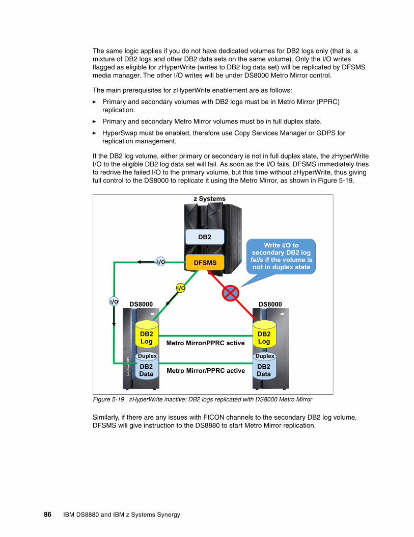
The same logic applies if you do not have dedicated volumes for DB2 logs only (that is, a mixture of DB2 logs and other DB2 data sets on the same volume). Only the I/O writes flagged as eligible for zHyperWrite (writes to DB2 log data set) will be replicated by DFSMS media manager. The other I/O writes will be under DS8000 Metro Mirror control.
The main prerequisites for zHyperWrite enablement are as follows:
� Primary and secondary volumes with DB2 logs must be in Metro Mirror (PPRC) replication.
� Primary and secondary Metro Mirror volumes must be in full duplex state.
� HyperSwap must be enabled, therefore use Copy Services Manager or GDPS for replication management.
If the DB2 log volume, either primary or secondary is not in full duplex state, the zHyperWrite I/O to the eligible DB2 log data set will fail. As soon as the I/O fails, DFSMS immediately tries to redrive the failed I/O to the primary volume, but this time without zHyperWrite, thus giving full control to the DS8000 to replicate it using the Metro Mirror, as shown in Figure 5-19.
Figure 5-19 zHyperWrite inactive: DB2 logs replicated with DS8000 Metro Mirror
Similarly, if there are any issues with FICON channels to the secondary DB2 log volume, DFSMS will give instruction to the DS8880 to start Metro Mirror replication.
DB2 Log
DB2
Metro Mirror/PPRC active
DFSMS
Write I/O to secondary DB2 log fails if the volume is not in duplex state
Metro Mirror/PPRC active
z Systems
DS8000 DS8000
DB2 Data
Duplex
DB2 Log
DB2 Data
Duplex
I/O
I/O
I/O
86 IBM DS8880 and IBM z Systems Synergy
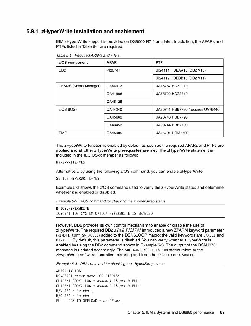
5.9.1 zHyperWrite installation and enablement
IBM zHyperWrite support is provided on DS8000 R7.4 and later. In addition, the APARs and PTFs listed in Table 5-1 are required.
Table 5-1 Required APARs and PTFs
The zHyeprWrite function is enabled by default as soon as the required APARs and PTFs are applied and all other zHyperWrite prerequisites are met. The zHyperWrite statement is included in the IECIOSxx member as follows:
HYPERWRITE=YES
Alternatively, by using the following z/OS command, you can enable zHyperWrite:
SETIOS HYPERWRITE=YES
Example 5-2 shows the z/OS command used to verify the zHyperWrite status and determine whether it is enabled or disabled.
Example 5-2 z/OS command for checking the zHyperSwap status
D IOS,HYPERWRITEIOS634I IOS SYSTEM OPTION HYPERWRITE IS ENABLED
However, DB2 provides its own control mechanism to enable or disable the use of zHyperWrite. The required DB2 APAR PI25747 introduced a new ZPARM keyword parameter (REMOTE_COPY_SW_ACCEL) added to the DSN6LOGP macro; the valid keywords are ENABLE and DISABLE. By default, this parameter is disabled. You can verify whether zHyperWrite is enabled by using the DB2 command shown in Example 5-3. The output of the DSNJ370I message is updated accordingly. The SOFTWARE ACCELERATION status refers to the zHyperWrite software controlled mirroring and it can be ENABLED or DISABLED.
Example 5-3 DB2 command for checking the zHyperSwap status
-DISPLAY LOGDSNJ370I csect-name LOG DISPLAYCURRENT COPY1 LOG = dsname1 IS pct % FULLCURRENT COPY2 LOG = dsname2 IS pct % FULLH/W RBA = hw-rba ,H/O RBA = ho-rbaFULL LOGS TO OFFLOAD = nn OF mm ,
z/OS component APAR PTF
DB2 PI25747 UI24111 HDBAA10 (DB2 V10)
UI24112 HDBBB10 (DB2 V11)
DFSMS (Media Manager) OA44973 UA75767 HDZ2210
OA41906 UA75722 HDZ2210
OA45125
z/OS (IOS) OA44240 UA90741 HBB7790 (requires UA76440)
OA45662 UA90746 HBB7790
OA43453 UA90744 HBB7790
RMF OA45985 UA75791 HRM7790
Chapter 5. IBM z Systems and DS8880 performance 87
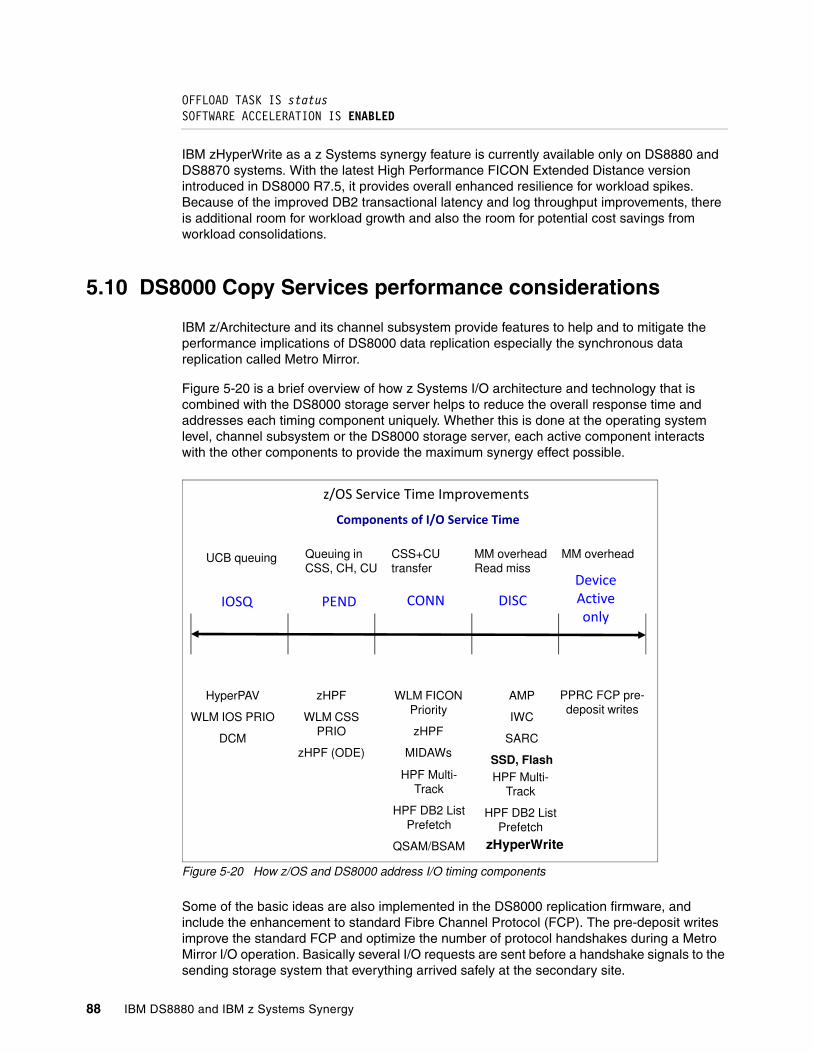
OFFLOAD TASK IS statusSOFTWARE ACCELERATION IS ENABLED
IBM zHyperWrite as a z Systems synergy feature is currently available only on DS8880 and DS8870 systems. With the latest High Performance FICON Extended Distance version introduced in DS8000 R7.5, it provides overall enhanced resilience for workload spikes. Because of the improved DB2 transactional latency and log throughput improvements, there is additional room for workload growth and also the room for potential cost savings from workload consolidations.
5.10 DS8000 Copy Services performance considerations
IBM z/Architecture and its channel subsystem provide features to help and to mitigate the performance implications of DS8000 data replication especially the synchronous data replication called Metro Mirror.
Figure 5-20 is a brief overview of how z Systems I/O architecture and technology that is combined with the DS8000 storage server helps to reduce the overall response time and addresses each timing component uniquely. Whether this is done at the operating system level, channel subsystem or the DS8000 storage server, each active component interacts with the other components to provide the maximum synergy effect possible.
Figure 5-20 How z/OS and DS8000 address I/O timing components
Some of the basic ideas are also implemented in the DS8000 replication firmware, and include the enhancement to standard Fibre Channel Protocol (FCP). The pre-deposit writes improve the standard FCP and optimize the number of protocol handshakes during a Metro Mirror I/O operation. Basically several I/O requests are sent before a handshake signals to the sending storage system that everything arrived safely at the secondary site.
�� � ������� �� �
���������������� �����������
��� � ����������������������
UCB queuing Queuing inCSS, CH, CU
CSS+CU transfer
MM overheadRead miss
������!���������
MM overhead
HyperPAV
WLM IOS PRIO
DCM
zHPF
WLM CSS PRIO
zHPF (ODE)
WLM FICON Priority
zHPF
MIDAWs
AMP
IWC
SARC
SSD, FlashHPF Multi-
Track
HPF DB2 List Prefetch
QSAM/BSAM
HPF Multi-Track
HPF DB2 List Prefetch
PPRC FCP pre-deposit writes
zHyperWrite
88 IBM DS8880 and IBM z Systems Synergy

So the number of protocol exchanges to execute the I/O chain is minimized compared to standard FCP. The art here is to combine several aspects, such as how many I/Os to send before the handshake, considering the resources needed for buffers, and how smart error detection and error recovery are to run at the maximal speed and performance. This approach allows providing good performance with the DS8000 when using Copy Services functions of up to 300 km distance between sites.
This technology is used by both DS8000 Copy Services functions and also by zHPF through Extended Distance II (see 5.6, “z High Performance FICON for IBM z Systems (zHPF)” on page 75).
Using PAVs and, even better, HyperPAV together with DS8000 multiple allegiance, and I/O priority queuing functions can significantly help to mitigate the potential performance impact through synchronous Metro Mirror replication. But, even without those extra performance improvement features, the Metro Mirror solution as implemented in the DS8000 is by itself one of the most efficient synchronous replication solution compared to other storage systems. With just a single round trip and considering the speed of light in a non-vacuum environment at approximately 200,000 km/sec, the synchronous Metro Mirror overhead is only 10 micro seconds per 1 km round trip. That means the synchronous replication overhead is just about 1 ms when both sites are 100 km apart.
Asynchronous usually has no affect on application write I/Os.
FlashCopy and performance lead to other considerations.
FlashCopy with background copy I/Os can sometimes briefly affect application write I/Os. When application writes must be destaged during background copy I/Os, the corresponding ranks can become over committed when the source volumes experience high I/O rates at the same time.
FlashCopy with NOCOPY forces back-end I/Os through copy on writes. Before a source track gets updated by an application write I/O, the source tracks are first copied to the FlashCopy target volume to preserve the data status from the last FlashCopy operation. This copy on write just happens once per track until the next FlashCopy NOCOPY operation.
When the FlashCopy target volume is a track space-efficient volume, the management overhead might become visible with high write I/O rates to the concerned source volume. Generally, a good practice is to secure performance, avoid space-efficient FlashCopy target volumes, and use a fully provisioned target volume instead. This approach also has an advantage that such a volume is not dedicated only to FlashCopy. This consideration is not applicable to Global Mirror (GM). Experience shows that with GM, a track space-efficient FlashCopy target volume provides sufficient performance to handle the incoming write I/O load at the GM secondary site. You are on the safe side with GM space-efficient FlashCopy target volumes when establishing the FlashCopy target volumes on the fastest DS8000 back-end storage technology. At least define the space-efficient FlashCopy repository in an extent pool with as many ranks as possible, and with them spread across as many device adapter pairs and DA pairs as possible.
Incremental FlashCopy provides potentially the best performance results. Just a full initial copy at the time of the first FlashCopy operation. After that, no data must be moved and changed tracks are just recorded as a bitmap until the next FlashCopy operation. Subsequent FlashCopy operations copy only the tracks that changed since the last FlashCopy.
Chapter 5. IBM z Systems and DS8880 performance 89
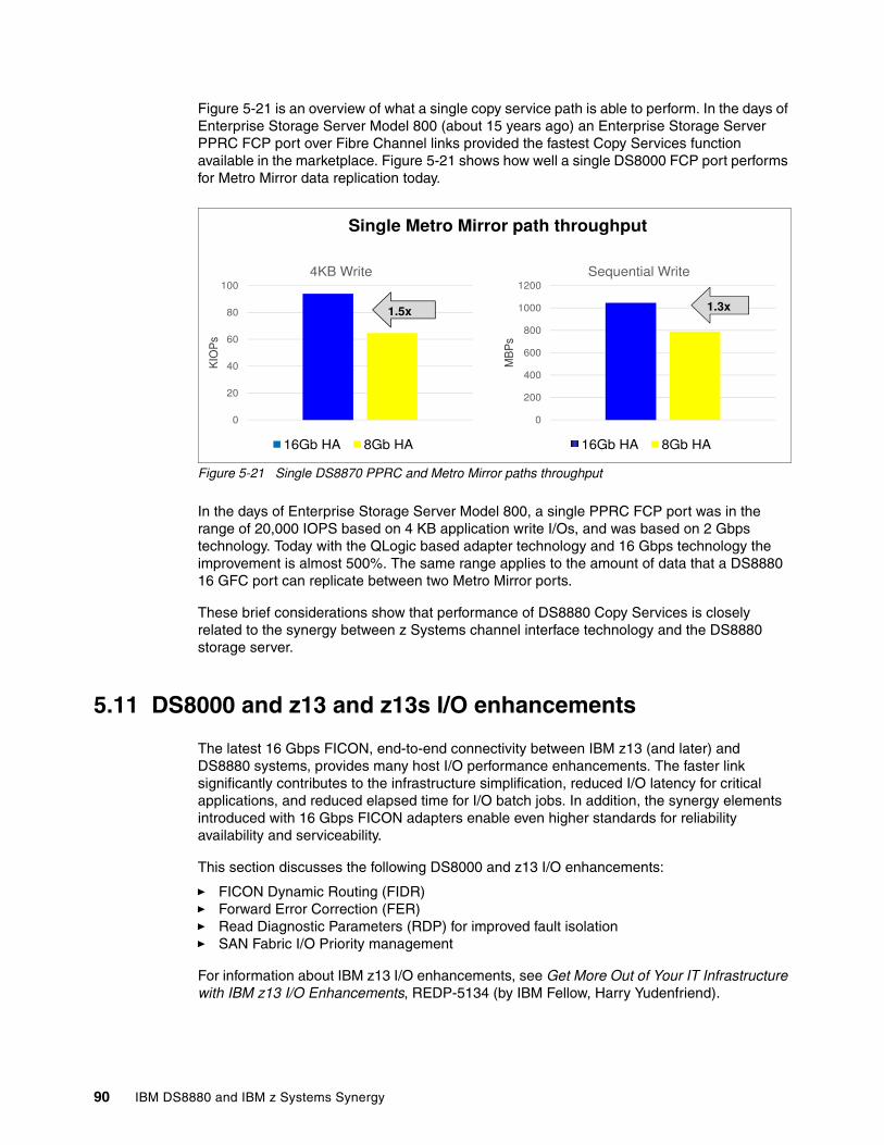
Figure 5-21 is an overview of what a single copy service path is able to perform. In the days of Enterprise Storage Server Model 800 (about 15 years ago) an Enterprise Storage Server PPRC FCP port over Fibre Channel links provided the fastest Copy Services function available in the marketplace. Figure 5-21 shows how well a single DS8000 FCP port performs for Metro Mirror data replication today.
Figure 5-21 Single DS8870 PPRC and Metro Mirror paths throughput
In the days of Enterprise Storage Server Model 800, a single PPRC FCP port was in the range of 20,000 IOPS based on 4 KB application write I/Os, and was based on 2 Gbps technology. Today with the QLogic based adapter technology and 16 Gbps technology the improvement is almost 500%. The same range applies to the amount of data that a DS8880 16 GFC port can replicate between two Metro Mirror ports.
These brief considerations show that performance of DS8880 Copy Services is closely related to the synergy between z Systems channel interface technology and the DS8880 storage server.
5.11 DS8000 and z13 and z13s I/O enhancements
The latest 16 Gbps FICON, end-to-end connectivity between IBM z13 (and later) and DS8880 systems, provides many host I/O performance enhancements. The faster link significantly contributes to the infrastructure simplification, reduced I/O latency for critical applications, and reduced elapsed time for I/O batch jobs. In addition, the synergy elements introduced with 16 Gbps FICON adapters enable even higher standards for reliability availability and serviceability.
This section discusses the following DS8000 and z13 I/O enhancements:
� FICON Dynamic Routing (FIDR)� Forward Error Correction (FER)� Read Diagnostic Parameters (RDP) for improved fault isolation� SAN Fabric I/O Priority management
For information about IBM z13 I/O enhancements, see Get More Out of Your IT Infrastructure with IBM z13 I/O Enhancements, REDP-5134 (by IBM Fellow, Harry Yudenfriend).
60
80
100
OP
s
4KB Write
600
800
1000
1200
BP
s
Sequential Write
PPRC Single Path
1.5x 1.3x
Single Metro Mirror path throughput
0
20
40KIO
16Gb HA 8Gb HA
0
200
400
600
MB
16Gb HA 8Gb HA
90 IBM DS8880 and IBM z Systems Synergy
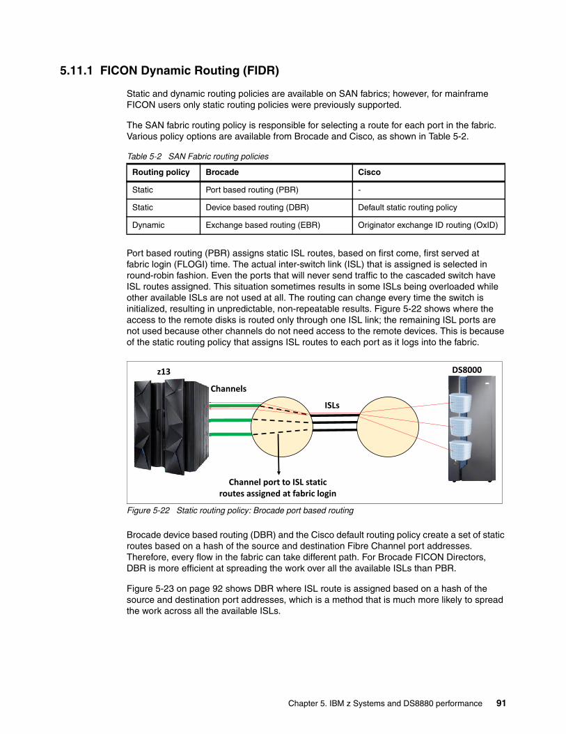
5.11.1 FICON Dynamic Routing (FIDR)
Static and dynamic routing policies are available on SAN fabrics; however, for mainframe FICON users only static routing policies were previously supported.
The SAN fabric routing policy is responsible for selecting a route for each port in the fabric. Various policy options are available from Brocade and Cisco, as shown in Table 5-2.
Table 5-2 SAN Fabric routing policies
Port based routing (PBR) assigns static ISL routes, based on first come, first served at fabric login (FLOGI) time. The actual inter-switch link (ISL) that is assigned is selected in round-robin fashion. Even the ports that will never send traffic to the cascaded switch have ISL routes assigned. This situation sometimes results in some ISLs being overloaded while other available ISLs are not used at all. The routing can change every time the switch is initialized, resulting in unpredictable, non-repeatable results. Figure 5-22 shows where the access to the remote disks is routed only through one ISL link; the remaining ISL ports are not used because other channels do not need access to the remote devices. This is because of the static routing policy that assigns ISL routes to each port as it logs into the fabric.
Figure 5-22 Static routing policy: Brocade port based routing
Brocade device based routing (DBR) and the Cisco default routing policy create a set of static routes based on a hash of the source and destination Fibre Channel port addresses. Therefore, every flow in the fabric can take different path. For Brocade FICON Directors, DBR is more efficient at spreading the work over all the available ISLs than PBR.
Figure 5-23 on page 92 shows DBR where ISL route is assigned based on a hash of the source and destination port addresses, which is a method that is much more likely to spread the work across all the available ISLs.
Routing policy Brocade Cisco
Static Port based routing (PBR) -
Static Device based routing (DBR) Default static routing policy
Dynamic Exchange based routing (EBR) Originator exchange ID routing (OxID)
Channels
ISLs
Channel port to ISL static routes assigned at fabric login
z13 DS8000
Chapter 5. IBM z Systems and DS8880 performance 91
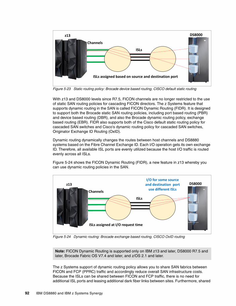
Figure 5-23 Static routing policy: Brocade device based routing, CISCO default static routing
With z13 and DS8000 levels since R7.5, FICON channels are no longer restricted to the use of static SAN routing policies for cascading FICON directors. The z Systems feature that supports dynamic routing in the SAN is called FICON Dynamic Routing (FIDR). It is designed to support both the Brocade static SAN routing policies, including port based routing (PBR) and device based routing (DBR), and also the Brocade dynamic routing policy, exchange based routing (EBR). FIDR also supports both of the Cisco default static routing policy for cascaded SAN switches and Cisco's dynamic routing policy for cascaded SAN switches, Originator Exchange ID Routing (OxID).
Dynamic routing dynamically changes the routes between host channels and DS8880 systems based on the Fibre Channel Exchange ID. Each I/O operation gets its own exchange ID. Therefore, all available ISL ports are evenly utilized because the host I/O traffic is routed evenly across all ISLs.
Figure 5-24 shows the FICON Dynamic Routing (FIDR), a new feature in z13 whereby you can use dynamic routing policies in the SAN.
Figure 5-24 Dynamic routing: Brocade exchange based routing, CISCO OxID routing
The z Systems support of dynamic routing policy allows you to share SAN fabrics between FICON and FCP (PPRC) traffic and accordingly reduce overall SAN infrastructure costs. Because the ISLs can be shared between FICON and FCP traffic, there is no need for additional ISL ports and leasing additional dark fiber links between sites. Furthermore, shared
Note: FICON Dynamic Routing is supported only on IBM z13 and later, DS8000 R7.5 and later, Brocade Fabric OS V7.4 and later, and z/OS 2.1 and later.
Channels
ISLs
z13 DS8000
ISLs assigned based on source and destination port
Channels
ISLs
z13 DS8000
ISLs assigned at I/O request time
I/O for some source and destination port
use different ISLs
92 IBM DS8880 and IBM z Systems Synergy
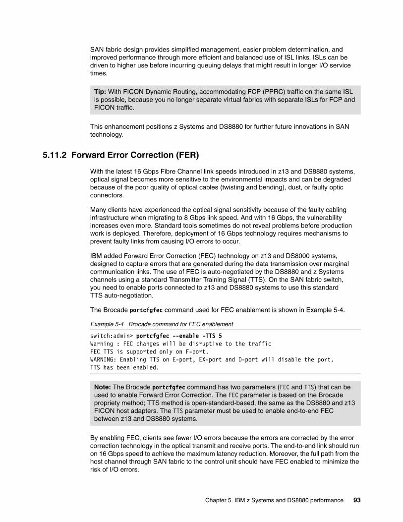
SAN fabric design provides simplified management, easier problem determination, and improved performance through more efficient and balanced use of ISL links. ISLs can be driven to higher use before incurring queuing delays that might result in longer I/O service times.
This enhancement positions z Systems and DS8880 for further future innovations in SAN technology.
5.11.2 Forward Error Correction (FER)
With the latest 16 Gbps Fibre Channel link speeds introduced in z13 and DS8880 systems, optical signal becomes more sensitive to the environmental impacts and can be degraded because of the poor quality of optical cables (twisting and bending), dust, or faulty optic connectors.
Many clients have experienced the optical signal sensitivity because of the faulty cabling infrastructure when migrating to 8 Gbps link speed. And with 16 Gbps, the vulnerability increases even more. Standard tools sometimes do not reveal problems before production work is deployed. Therefore, deployment of 16 Gbps technology requires mechanisms to prevent faulty links from causing I/O errors to occur.
IBM added Forward Error Correction (FEC) technology on z13 and DS8000 systems, designed to capture errors that are generated during the data transmission over marginal communication links. The use of FEC is auto-negotiated by the DS8880 and z Systems channels using a standard Transmitter Training Signal (TTS). On the SAN fabric switch, you need to enable ports connected to z13 and DS8880 systems to use this standard TTS auto-negotiation.
The Brocade portcfgfec command used for FEC enablement is shown in Example 5-4.
Example 5-4 Brocade command for FEC enablement
switch:admin> portcfgfec --enable -TTS 5Warning : FEC changes will be disruptive to the trafficFEC TTS is supported only on F-port.WARNING: Enabling TTS on E-port, EX-port and D-port will disable the port.TTS has been enabled.
By enabling FEC, clients see fewer I/O errors because the errors are corrected by the error correction technology in the optical transmit and receive ports. The end-to-end link should run on 16 Gbps speed to achieve the maximum latency reduction. Moreover, the full path from the host channel through SAN fabric to the control unit should have FEC enabled to minimize the risk of I/O errors.
Tip: With FICON Dynamic Routing, accommodating FCP (PPRC) traffic on the same ISL is possible, because you no longer separate virtual fabrics with separate ISLs for FCP and FICON traffic.
Note: The Brocade portcfgfec command has two parameters (FEC and TTS) that can be used to enable Forward Error Correction. The FEC parameter is based on the Brocade propriety method; TTS method is open-standard-based, the same as the DS8880 and z13 FICON host adapters. The TTS parameter must be used to enable end-to-end FEC between z13 and DS8880 systems.
Chapter 5. IBM z Systems and DS8880 performance 93
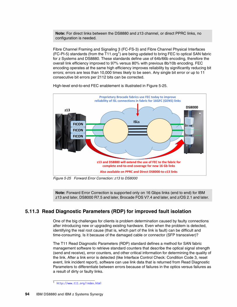
Fibre Channel Framing and Signaling 3 (FC-FS-3) and Fibre Channel Physical Interfaces (FC-PI-5) standards (from the T11.org1) are being updated to bring FEC to optical SAN fabric for z Systems and DS8880. These standards define use of 64b/66b encoding, therefore the overall link efficiency improved to 97% versus 80% with previous 8b/10b encoding. FEC encoding operates at the same high efficiency improves reliability by significantly reducing bit errors; errors are less than 10,000 times likely to be seen. Any single bit error or up to 11 consecutive bit errors per 2112 bits can be corrected.
High-level end-to-end FEC enablement is illustrated in Figure 5-25.
Figure 5-25 Forward Error Correction: z13 to DS8000
5.11.3 Read Diagnostic Parameters (RDP) for improved fault isolation
One of the big challenges for clients is problem determination caused by faulty connections after introducing new or upgrading existing hardware. Even when the problem is detected, identifying the real root cause (that is, which part of the link is fault) can be difficult and time-consuming. Is it because of the damaged cable or connector (SFP transceiver)?
The T11 Read Diagnostic Parameters (RDP) standard defines a method for SAN fabric management software to retrieve standard counters that describe the optical signal strength (send and receive), error counters, and other critical information for determining the quality of the link. After a link error is detected (like Interface Control Check: Condition Code 3, reset event, link incident report), software can use link data that is returned from Read Diagnostic Parameters to differentiate between errors because of failures in the optics versus failures as a result of dirty or faulty links.
Note: For direct links between the DS8880 and z13 channel, or direct PPRC links, no configuration is needed.
1 http://www.t11.org/index.html
Note: Forward Error Correction is supported only on 16 Gbps links (end to end) for IBM z13 and later, DS8000 R7.5 and later, Brocade FOS V7.4 and later, and z/OS 2.1 and later.
ISLs
z13DS8000
FICONFICONFICON
Proprietary Brocade fabrics use FEC today to improve reliability of ISL connections in fabric for 16GFC (GEN5) links
z13 and DS8880 will extend the use of FEC to the fabric for complete end-to-end coverage for new 16 Gb links
Also available on PPRC and Direct DS8000-to-z13 links
94 IBM DS8880 and IBM z Systems Synergy
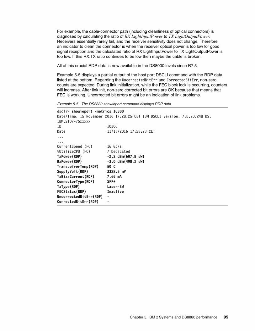
For example, the cable-connector path (including cleanliness of optical connectors) is diagnosed by calculating the ratio of RX LightInputPower to TX LightOutputPower. Receivers essentially rarely fail, and the receiver sensitivity does not change. Therefore, an indicator to clean the connector is when the receiver optical power is too low for good signal reception and the calculated ratio of RX LightInputPower to TX LightOutputPower is too low. If this RX:TX ratio continues to be low then maybe the cable is broken.
All of this crucial RDP data is now available in the DS8000 levels since R7.5.
Example 5-5 displays a partial output of the host port DSCLI command with the RDP data listed at the bottom. Regarding the UncorrectedBitErr and CorrectedBitErr, non-zero counts are expected. During link initialization, while the FEC block lock is occurring, counters will increase. After link init, non-zero corrected bit errors are OK because that means that FEC is working. Uncorrected bit errors might be an indication of link problems.
Example 5-5 The DS8880 showioport command displays RDP data
dscli> showioport -metrics I0300Date/Time: 15 November 2016 17:28:25 CET IBM DSCLI Version: 7.8.20.248 DS: IBM.2107-75xxxxxID I0300Date 11/15/2016 17:28:23 CET......CurrentSpeed (FC) 16 Gb/s%UtilizeCPU (FC) 7 DedicatedTxPower(RDP) -2.2 dBm(607.8 uW)RxPower(RDP) -3.0 dBm(498.2 uW)TransceiverTemp(RDP) 50 CSupplyVolt(RDP) 3328.5 mVTxBiasCurrent(RDP) 7.66 mAConnectorType(RDP) SFP+TxType(RDP) Laser-SWFECStatus(RDP) InactiveUncorrectedBitErr(RDP) -CorrectedBitErr(RDP) -
Chapter 5. IBM z Systems and DS8880 performance 95
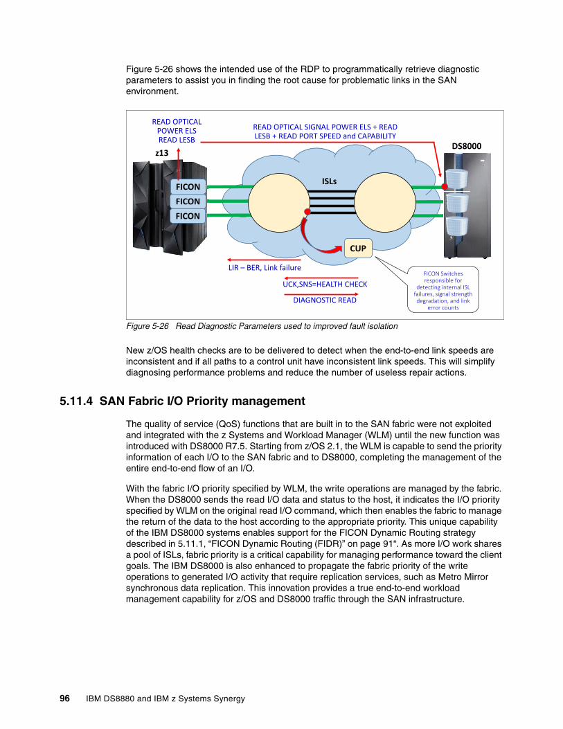
Figure 5-26 shows the intended use of the RDP to programmatically retrieve diagnostic parameters to assist you in finding the root cause for problematic links in the SAN environment.
Figure 5-26 Read Diagnostic Parameters used to improved fault isolation
New z/OS health checks are to be delivered to detect when the end-to-end link speeds are inconsistent and if all paths to a control unit have inconsistent link speeds. This will simplify diagnosing performance problems and reduce the number of useless repair actions.
5.11.4 SAN Fabric I/O Priority management
The quality of service (QoS) functions that are built in to the SAN fabric were not exploited and integrated with the z Systems and Workload Manager (WLM) until the new function was introduced with DS8000 R7.5. Starting from z/OS 2.1, the WLM is capable to send the priority information of each I/O to the SAN fabric and to DS8000, completing the management of the entire end-to-end flow of an I/O.
With the fabric I/O priority specified by WLM, the write operations are managed by the fabric. When the DS8000 sends the read I/O data and status to the host, it indicates the I/O priority specified by WLM on the original read I/O command, which then enables the fabric to manage the return of the data to the host according to the appropriate priority. This unique capability of the IBM DS8000 systems enables support for the FICON Dynamic Routing strategy described in 5.11.1, “FICON Dynamic Routing (FIDR)” on page 91“. As more I/O work shares a pool of ISLs, fabric priority is a critical capability for managing performance toward the client goals. The IBM DS8000 is also enhanced to propagate the fabric priority of the write operations to generated I/O activity that require replication services, such as Metro Mirror synchronous data replication. This innovation provides a true end-to-end workload management capability for z/OS and DS8000 traffic through the SAN infrastructure.
ISLs
z13DS8000
FICONFICONFICON
CUP
FICON Switches responsible for
detecting internal ISL failures, signal strength degradation, and link
error counts
READ OPTICAL SIGNAL POWER ELS + READ LESB + READ PORT SPEED and CAPABILITY
READ OPTICAL POWER ELS READ LESB
LIR – BER, Link failure
UCK,SNS=HEALTH CHECK
DIAGNOSTIC READ
96 IBM DS8880 and IBM z Systems Synergy
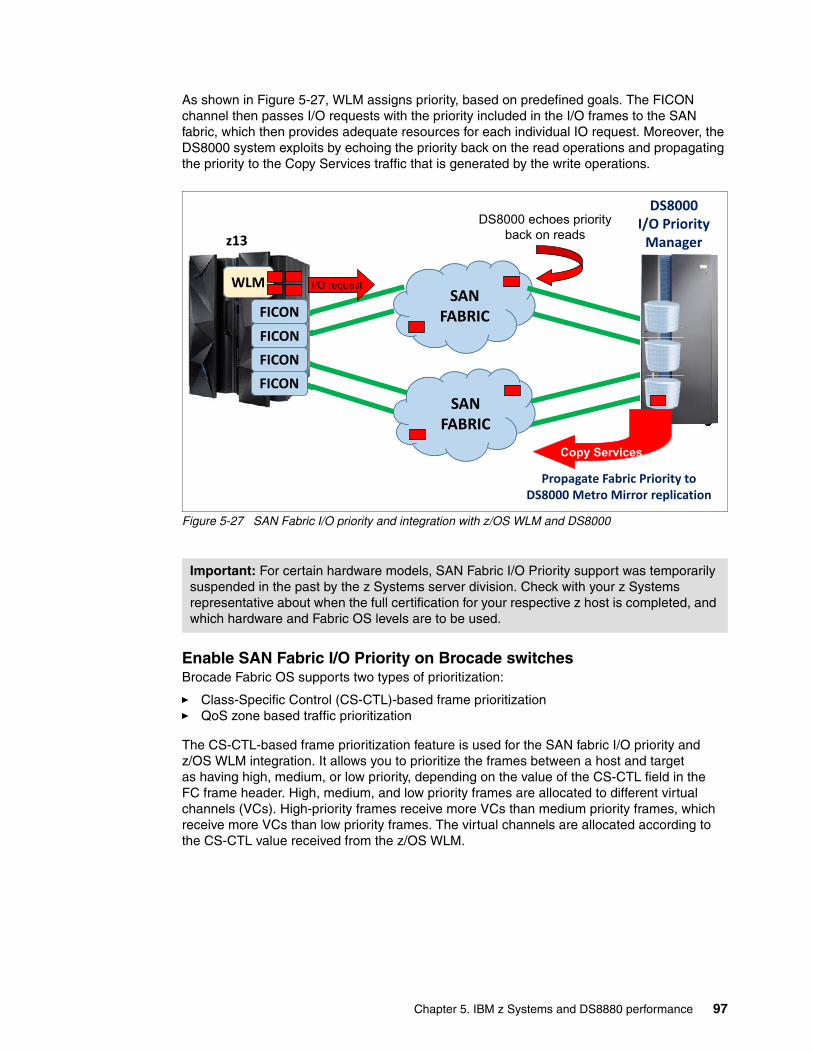
As shown in Figure 5-27, WLM assigns priority, based on predefined goals. The FICON channel then passes I/O requests with the priority included in the I/O frames to the SAN fabric, which then provides adequate resources for each individual IO request. Moreover, the DS8000 system exploits by echoing the priority back on the read operations and propagating the priority to the Copy Services traffic that is generated by the write operations.
Figure 5-27 SAN Fabric I/O priority and integration with z/OS WLM and DS8000
Enable SAN Fabric I/O Priority on Brocade switchesBrocade Fabric OS supports two types of prioritization:
� Class-Specific Control (CS-CTL)-based frame prioritization� QoS zone based traffic prioritization
The CS-CTL-based frame prioritization feature is used for the SAN fabric I/O priority and z/OS WLM integration. It allows you to prioritize the frames between a host and target as having high, medium, or low priority, depending on the value of the CS-CTL field in the FC frame header. High, medium, and low priority frames are allocated to different virtual channels (VCs). High-priority frames receive more VCs than medium priority frames, which receive more VCs than low priority frames. The virtual channels are allocated according to the CS-CTL value received from the z/OS WLM.
Important: For certain hardware models, SAN Fabric I/O Priority support was temporarily suspended in the past by the z Systems server division. Check with your z Systems representative about when the full certification for your respective z host is completed, and which hardware and Fabric OS levels are to be used.
SAN FABRIC
z13
DS8000 I/O Priority
Manager
FICONFICONFICON
WLM
Propagate Fabric Priority to DS8000 Metro Mirror replication
SAN FABRIC
I/O request
FICON
DS8000 echoes priority
back on reads
Copy Services
Chapter 5. IBM z Systems and DS8880 performance 97
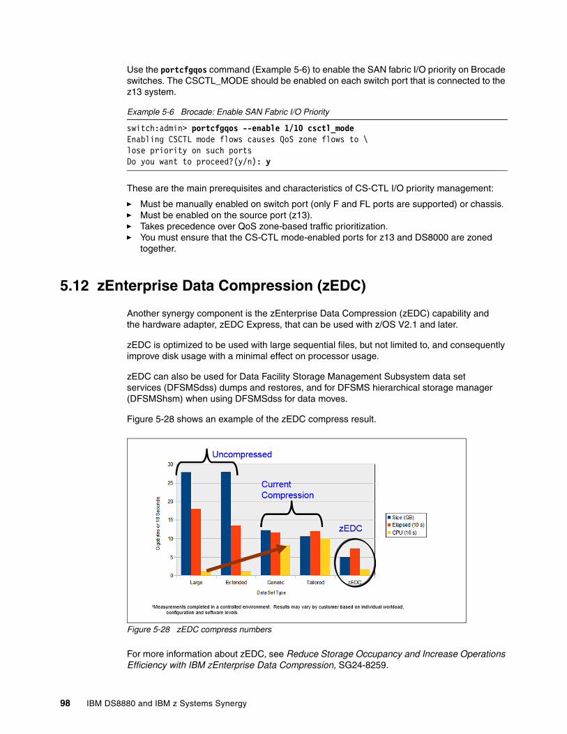
Use the portcfgqos command (Example 5-6) to enable the SAN fabric I/O priority on Brocade switches. The CSCTL_MODE should be enabled on each switch port that is connected to the z13 system.
Example 5-6 Brocade: Enable SAN Fabric I/O Priority
switch:admin> portcfgqos --enable 1/10 csctl_modeEnabling CSCTL mode flows causes QoS zone flows to \lose priority on such portsDo you want to proceed?(y/n): y
These are the main prerequisites and characteristics of CS-CTL I/O priority management:
� Must be manually enabled on switch port (only F and FL ports are supported) or chassis. � Must be enabled on the source port (z13).� Takes precedence over QoS zone-based traffic prioritization.� You must ensure that the CS-CTL mode-enabled ports for z13 and DS8000 are zoned
together.
5.12 zEnterprise Data Compression (zEDC)
Another synergy component is the zEnterprise Data Compression (zEDC) capability and the hardware adapter, zEDC Express, that can be used with z/OS V2.1 and later.
zEDC is optimized to be used with large sequential files, but not limited to, and consequently improve disk usage with a minimal effect on processor usage.
zEDC can also be used for Data Facility Storage Management Subsystem data set services (DFSMSdss) dumps and restores, and for DFSMS hierarchical storage manager (DFSMShsm) when using DFSMSdss for data moves.
Figure 5-28 shows an example of the zEDC compress result.
Figure 5-28 zEDC compress numbers
For more information about zEDC, see Reduce Storage Occupancy and Increase Operations Efficiency with IBM zEnterprise Data Compression, SG24-8259.
98 IBM DS8880 and IBM z Systems Synergy
Related publications
The publications listed in this section are considered particularly suitable for a more detailed discussion of the topics covered in this paper.
IBM Redbooks
The following Redbooks publications provide more information about the topic in this document. Note that some publications might be available in softcopy only.
� DB2 for z/OS and List Prefetch Optimizer, REDP-4862
� DFSMShsm Fast Replication Technical Guide, SG24-7069
� DS8000 I/O Priority Manager, REDP-4760
� DS8870 Data Migration Techniques, SG24-8257
� DS8870 Easy Tier Application, REDP-5014
� DS8880 High Performance Flash Enclosure Gen2, REDP-5422
� Enhancing Value to Existing and Future Workloads with IBM z13, REDP-5135
� Get More Out of Your IT Infrastructure with IBM z13 I/O Enhancements, REDP-5134
� How does the MIDAW Facility Improve the Performance of FICON Channels Using DB2 and other workloads?, REDP-4201
� IBM DS8000 EasyTier, REDP-4667
� IBM DS8870 Easy Tier Heat Map Transfer, REDP-5015
� IBM DS8870 Multiple Target Peer-to-Peer Remote Copy, REDP-5151
� IBM DS8880 Architecture and Implementation (Release 8.1), SG24-8323
� IBM DS8880 Product Guide (Release 8.2.1), REDP-5344
� IBM DS8880 Thin Provisioning, REDP-5343
� IBM GDPS Family: An Introduction to Concepts and Capabilities, SG24-6374
� IBM System Storage DS8000: Host Attachment and Interoperability, SG24-8887
� IBM z Systems Connectivity Handbook, SG24-5444
� IBM z13 and IBM z13s Technical Introduction, SG24-8250
� IBM z/OS Global Mirror Planning, Operations, and Best Practices, REDP-4878
� IBM z/OS V2R2: Storage Management and Utilities, SG24-8289
� Multiple Subchannel Sets: An Implementation View, REDP-4387
� Reduce Storage Occupancy and Increase Operations Efficiency with IBM zEnterprise Data Compression, SG24-8259
� System z End-to-End Extended Distance Guide, SG24-8047
You can search for, view, download or order these documents and other Redbooks, Redpapers, Web Docs, draft and additional materials, at the following website:
ibm.com/redbooks
© Copyright IBM Corp. 2015, 2017. All rights reserved. 99
Other publications
These publications are also relevant as further information sources:
� IBM IMS High Performance Image Copy for z/OS, Version 4 Release 2, User’s Guide, SC19-2756
� z/OS DFSMS Advanced Copy Services, SC23-6847-02
� z/OS DFSMS Using the New Functions Version 2 Release 1, SC23-6857-03
� z/OS DFSMS Using the New Functions Version 2 Release 2, SC23-6857-04
� z/OS DFSMSdfp Storage Administration Version 2 Release 1, SC23-6860-01
� z/OS DFSMSdfp Storage Administration Version 2 Release 2, SC23-6860-02
� IBM System Storage DS8880 Performance Whitepaper, by Joshua Martin et al., August 2016, WP102605
Online resources
These websites are also relevant as further information sources:
� IBM z Systems product page
http://www.ibm.com/systems/z/?lnk=mprSY-sysz-usen
� IBM DS8000 series product
http://www.ibm.com/systems/storage/disk/ds8000/index.html
Help from IBM
IBM Support and downloads
ibm.com/support
IBM Global Services
ibm.com/services
100 IBM DS8880 and IBM z Systems Synergy

ibm.com/redbooks
Printed in U.S.A.
Back cover
ISBN 0738455946
REDP-5186-01
®