ibm infoprint 1116 - incos 1116...laser notices vii infoprint 1116 laser notices the following laser...
TRANSCRIPT

Edition: September 2001
The following paragraph does not apply to any country where such provisions are inconsistent with local law: LEXMARK INTERNATIONAL, INC. PROVIDES THIS PUBLICATION “AS IS” WITHOUT WARRANTY OF ANY KIND, EITHER EXPRESS OR IMPLIED, INCLUDING, BUT NOT LIMITED TO, THE IMPLIED WARRANTIES OF MERCHANTABILITY OR FITNESS FOR A PARTICULAR PURPOSE. Some states do not allow disclaimer of express or implied warranties in certain transactions; therefore, this statement may not apply to you.
This publication could include technical inaccuracies or typographical errors. Changes are periodically made to the information herein; these changes will be incorporated in later editions. Improvements or changes in the products or the programs described may be made at any time.
Comments may be addressed to Lexmark International, Inc., Department D22A/032-2, 740 West New Circle Road, Lexington, Kentucky 40550, U.S.A or e-mail at [email protected]. Lexmark may use or distribute any of the information you supply in any way it believes appropriate without incurring any obligation to you. You can purchase additional copies of publications related to this product by calling 1-800-553-9727. In other countries, contact your point of purchase.
Lexmark, Lexmark with diamond design, ImageQuick, and MarkVision are trademarks of Lexmark International, Inc., registered in the United States and/or other countries.
Other trademarks are the property of their respective owners.
© Copyright Lexmark International, Inc. 2001.All rights reserved.
UNITED STATES GOVERNMENT RESTRICTED RIGHTSThis software and documentation are provided with RESTRICTED RIGHTS. Use, duplication or disclosure by the Government is subject to restrictions as set forth in subparagraph (c)(1)(ii) of the Rights in Technical Data and Computer Software clause at DFARS 252.227-7013 and in applicable FAR provisions: Lexmark International, Inc., Lexington, KY 40550.
IBM Infoprint 1116
Infoprint 1116
Table of Contents
Laser Notices. . . . . . . . . . . . . . . . . . . . . . . . . . . . . . . . . . . . . . . . . vii
Safety Information. . . . . . . . . . . . . . . . . . . . . . . . . . . . . . . . . . . . xvii
Preface . . . . . . . . . . . . . . . . . . . . . . . . . . . . . . . . . . . . . . . . . . . . . xxii
General Information . . . . . . . . . . . . . . . . . . . . . . . . . . . . . . . . . . 1-1
Model Differences . . . . . . . . . . . . . . . . . . . . . . . . . . . . . . . . 1-1Printer Operation. . . . . . . . . . . . . . . . . . . . . . . . . . . . . . . . . 1-1Printer Dimensions and Clearance . . . . . . . . . . . . . . . . . . . 1-2Options . . . . . . . . . . . . . . . . . . . . . . . . . . . . . . . . . . . . . . . . 1-3Acronyms . . . . . . . . . . . . . . . . . . . . . . . . . . . . . . . . . . . . . . 1-4
Diagnostic Information . . . . . . . . . . . . . . . . . . . . . . . . . . . . . . . 2-1
Operator Panel . . . . . . . . . . . . . . . . . . . . . . . . . . . . . . . . . . . . 2-2Status Information . . . . . . . . . . . . . . . . . . . . . . . . . . . . . . . . 2-3Attendance Information . . . . . . . . . . . . . . . . . . . . . . . . . . . . 2-4
Service Information . . . . . . . . . . . . . . . . . . . . . . . . . . . . . . . . . 2-7Service Error Codes . . . . . . . . . . . . . . . . . . . . . . . . . . . . . 2-11Operator Panel LED Summary Table . . . . . . . . . . . . . . . . 2-28Error Code Table. . . . . . . . . . . . . . . . . . . . . . . . . . . . . . . . 2-28Power–On Self Test (POST). . . . . . . . . . . . . . . . . . . . . . . 2-36Symptom Tables . . . . . . . . . . . . . . . . . . . . . . . . . . . . . . . . 2-36
Service Checks . . . . . . . . . . . . . . . . . . . . . . . . . . . . . . . . . . . 2-39Cooling Fan Service Check. . . . . . . . . . . . . . . . . . . . . . . . 2-40Cover Interlock Switch Service Check . . . . . . . . . . . . . . . 2-40Engine Board Service Check . . . . . . . . . . . . . . . . . . . . . . 2-41Dead Machine Service Check. . . . . . . . . . . . . . . . . . . . . . 2-43Low Voltage Power Supply (LVPS) Service Check . . . . . 2-44Fuser Service Check. . . . . . . . . . . . . . . . . . . . . . . . . . . . . 2-45Cold Fuser Service Check . . . . . . . . . . . . . . . . . . . . . . . . 2-47Hot Fuser Service Check . . . . . . . . . . . . . . . . . . . . . . . . . 2-48Main Motor Service Check . . . . . . . . . . . . . . . . . . . . . . . . 2-48Operator Panel Service Check . . . . . . . . . . . . . . . . . . . . . 2-49Operator Panel Button Service Check . . . . . . . . . . . . . . . 2-50Paper Feed Service Checks . . . . . . . . . . . . . . . . . . . . . . . 2-51Parallel Port Service Check . . . . . . . . . . . . . . . . . . . . . . . 2-54Print Quality Service Checks. . . . . . . . . . . . . . . . . . . . . . . 2-55Solving Print Quality Problems . . . . . . . . . . . . . . . . . . . . . 2-62Resetting User Defaults . . . . . . . . . . . . . . . . . . . . . . . . . . 2-70Using the Special Function Menu . . . . . . . . . . . . . . . . . . . 2-71
iii
Infoprint 1116
Restoring Factory Defaults. . . . . . . . . . . . . . . . . . . . . . . . 2-72Using Hex Trace Mode. . . . . . . . . . . . . . . . . . . . . . . . . . . 2-73Using Print Quality Test Pages . . . . . . . . . . . . . . . . . . . . 2-74Advanced Troubleshooting Mode. . . . . . . . . . . . . . . . . . . 2-75
Diagnostic Aids . . . . . . . . . . . . . . . . . . . . . . . . . . . . . . . . . . . . . 3-1
Start . . . . . . . . . . . . . . . . . . . . . . . . . . . . . . . . . . . . . . . . . . . . 3-1Performing Self Test. . . . . . . . . . . . . . . . . . . . . . . . . . . . . . 3-1Information Priority . . . . . . . . . . . . . . . . . . . . . . . . . . . . . . . 3-1
Printer Operation Modes . . . . . . . . . . . . . . . . . . . . . . . . . . . . 3-2Printer Modes Summary Table . . . . . . . . . . . . . . . . . . . . . . . . 3-3
Normal Printing Mode. . . . . . . . . . . . . . . . . . . . . . . . . . . . . 3-6Demo Printing Mode. . . . . . . . . . . . . . . . . . . . . . . . . . . . . . 3-7Printing Menu Settings Page . . . . . . . . . . . . . . . . . . . . . . . 3-8Diagnostic Tests Mode. . . . . . . . . . . . . . . . . . . . . . . . . . . . 3-9Special Function Menu. . . . . . . . . . . . . . . . . . . . . . . . . . . 3-11Configuration Mode . . . . . . . . . . . . . . . . . . . . . . . . . . . . . 3-14
Repair Information . . . . . . . . . . . . . . . . . . . . . . . . . . . . . . . . . . . 4-1
Handling ESD-Sensitive Parts . . . . . . . . . . . . . . . . . . . . . . . . 4-1Removal Procedures . . . . . . . . . . . . . . . . . . . . . . . . . . . . . . . 4-2
Cover Removals. . . . . . . . . . . . . . . . . . . . . . . . . . . . . . . . . 4-2Auto Sheet Feed (ASF) Assembly Removal . . . . . . . . . . . 4-3Printhead Assembly Removal . . . . . . . . . . . . . . . . . . . . . . 4-4Controller Board Removal . . . . . . . . . . . . . . . . . . . . . . . . . 4-4Controller Board Cage Removal . . . . . . . . . . . . . . . . . . . . 4-4High Voltage Power Supply (HVPS) Removal . . . . . . . . . 4-5Cooling Fan Removal. . . . . . . . . . . . . . . . . . . . . . . . . . . . . 4-5Low Voltage Power Supply (LVPS) Removal. . . . . . . . . . . 4-5Engine Board Removal . . . . . . . . . . . . . . . . . . . . . . . . . . . 4-6Charge Roll Assembly Removal. . . . . . . . . . . . . . . . . . . . . 4-6Fuser Assembly Removal . . . . . . . . . . . . . . . . . . . . . . . . . 4-6Transfer Roll Removal . . . . . . . . . . . . . . . . . . . . . . . . . . . . 4-7Paper Feed Clutch Solenoid Removal . . . . . . . . . . . . . . . . 4-7D Roll Removal . . . . . . . . . . . . . . . . . . . . . . . . . . . . . . . . . 4-8
Connector Locations . . . . . . . . . . . . . . . . . . . . . . . . . . . . . . . . . 5-1
LVPS – Low Voltage Power Supply Board . . . . . . . . . . . . 5-1Engine Board . . . . . . . . . . . . . . . . . . . . . . . . . . . . . . . . . . . 5-2RIP Controller . . . . . . . . . . . . . . . . . . . . . . . . . . . . . . . . . . 5-6HVPS – High Voltage Power Supply Board . . . . . . . . . . . . 5-7Option Card . . . . . . . . . . . . . . . . . . . . . . . . . . . . . . . . . . . . 5-8
Preventive Maintenance . . . . . . . . . . . . . . . . . . . . . . . . . . . . . . 6-1
iv Service Manual

Infoprint 1116
Parts Catalog . . . . . . . . . . . . . . . . . . . . . . . . . . . . . . . . . . . . . . . 7-1
How to Use this Parts Catalog . . . . . . . . . . . . . . . . . . . . . . . . 7-1Assembly 1: Covers . . . . . . . . . . . . . . . . . . . . . . . . . . . . . . . . 7-2Assembly 2: Frame . . . . . . . . . . . . . . . . . . . . . . . . . . . . . . . . . 7-4Assembly 3: Fuser . . . . . . . . . . . . . . . . . . . . . . . . . . . . . . . . . 7-6Assembly 4: Main Drive . . . . . . . . . . . . . . . . . . . . . . . . . . . . . 7-8Assembly 5: Paper Feed . . . . . . . . . . . . . . . . . . . . . . . . . . . . 7-10Assembly 6: Printhead . . . . . . . . . . . . . . . . . . . . . . . . . . . . . 7-12Assembly 7: Electronics . . . . . . . . . . . . . . . . . . . . . . . . . . . . 7-14Assembly 8: Options . . . . . . . . . . . . . . . . . . . . . . . . . . . . . . . 7-16Assembly 9: Cables (no illustration) . . . . . . . . . . . . . . . . . . . . 7-18Assembly 10: Miscellaneous (no illustration) . . . . . . . . . . . . . 7-20
Index . . . . . . . . . . . . . . . . . . . . . . . . . . . . . . . . . . . . . . . . . . . . . . . .I-1
v

Infoprint 1116
vi Service Manual
Infoprint 1116
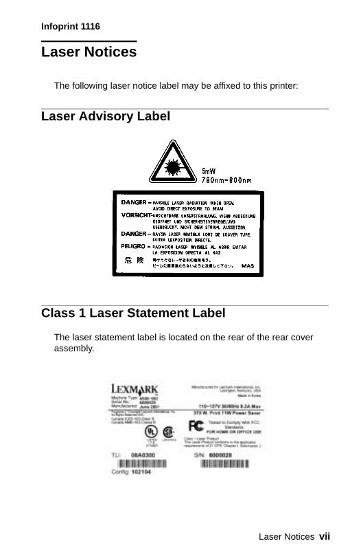
Laser Notices
The following laser notice label may be affixed to this printer:
Laser Advisory Label
Class 1 Laser Statement Label
The laser statement label is located on the rear of the rear cover assembly.
Laser Notices vii

Infoprint 1116
viii Service Manual
Infoprint 1116
Laser Notice
The printer is certified in the U.S. to conform to the requirements of DHHS 21 CFR Subchapter J for Class I (1) laser products, and elsewhere is certified as a Class I laser product conforming to the requirements of IEC 60825.
Class I laser products are not considered to be hazardous. The printer contains internally a Class IIIb (3b) laser that is nominally a 5 milliwatt gallium arsenide laser operating in the wavelength region of 770-795 nanometers. The laser system and printer are designed so there is never any human access to laser radiation above a Class I level during normal operation, user maintenance, or prescribed service condition.
Laser
Der Drucker erfüllt gemäß amtlicher Bestätigung der USA die Anforderungen der Bestimmung DHHS (Department of Health and Human Services) 21 CFR Teil J für Laserprodukte der Klasse I (1). In anderen Ländern gilt der Drucker als Laserprodukt der Klasse I, der die Anforderungen der IEC (International Electrotechnical Commission) 60825 gemäß amtlicher Bestätigung erfüllt.
Laserprodukte der Klasse I gelten als unschädlich. Im Inneren des Druckers befindet sich ein Laser der Klasse IIIb (3b), bei dem es sich um einen Galliumarsenlaser mit 5 Milliwatt handelt, der Wellen der Länge 770-795 Nanometer ausstrahlt. Das Lasersystem und der Drucker sind so konzipiert, daß im Normalbetrieb, bei der Wartung durch den Benutzer oder bei ordnungsgemäßer Wartung durch den Kundendienst Laserbestrahlung, die die Klasse I übersteigen würde, Menschen keinesfalls erreicht.
Laser Notices ix
Infoprint 1116
Avis relatif à l’utilisation de laser
Pour les Etats-Unis : cette imprimante est certifiée conforme aux provisions DHHS 21 CFR alinéa J concernant les produits laser de Classe I (1). Pour les autres pays : cette imprimante répond aux normes IEC 60825 relatives aux produits laser de Classe I.
Les produits laser de Classe I sont considérés comme des produits non dangereux. Cette imprimante est équipée d’un laser de Classe IIIb (3b) (arséniure de gallium d’une puissance nominale de 5 milliwatts) émettant sur des longueurs d’onde comprises entre 770 et 795 nanomètres. L’imprimante et son système laser sont conçus pour impossible, dans des conditions normales d’utilisation, d’entretien par l’utilisateur ou de révision, l’exposition à des rayonnements laser supérieurs à des rayonnements de Classe I .
Avvertenze sui prodotti laser
Questa stampante è certificata negli Stati Uniti per essere conforme ai requisiti del DHHS 21 CFR Sottocapitolo J per i prodotti laser di classe 1 ed è certificata negli altri Paesi come prodotto laser di classe 1 conforme ai requisiti della norma CEI 60825.
I prodotti laser di classe non sono considerati pericolosi. La stampante contiene al suo interno un laser di classe IIIb (3b) all’arseniuro di gallio della potenza di 5mW che opera sulla lunghezza d’onda compresa tra 770 e 795 nanometri. Il sistema laser e la stampante sono stati progettati in modo tale che le persone a contatto con la stampante, durante il normale funzionamento, le operazioni di servizio o quelle di assistenza tecnica, non ricevano radiazioni laser superiori al livello della classe 1.
x Service Manual
Infoprint 1116
Avisos sobre el láser
Se certifica que, en los EE.UU., esta impresora cumple los requisitos para los productos láser de Clase I (1) establecidos en el subcapítulo J de la norma CFR 21 del DHHS (Departamento de Sanidad y Servicios) y, en los demás países, reúne todas las condiciones expuestas en la norma IEC 60825 para productos láser de Clase I (1).
Los productos láser de Clase I no se consideran peligrosos. La impresora contiene en su interior un láser de Clase IIIb (3b) de arseniuro de galio de funcionamiento nominal a 5 milivatios en una longitud de onda de 770 a 795 nanómetros. El sistema láser y la impresora están diseñados de forma que ninguna persona pueda verse afectada por ningún tipo de radiación láser superior al nivel de la Clase I durante su uso normal, el mantenimiento realizado por el usuario o cualquier otra situación de servicio técnico.
Declaração sobre Laser
A impressora está certificada nos E.U.A. em conformidade com os requisitos da regulamentação DHHS 21 CFR Subcapítulo J para a Classe I (1) de produtos laser. Em outros locais, está certificada como um produto laser da Classe I, em conformidade com os requisitos da norma IEC 60825.
Os produtos laser da Classe I não são considerados perigosos. Internamente, a impressora contém um produto laser da Classe IIIb (3b), designado laser de arseneto de potássio, de 5 milliwatts ,operando numa faixa de comprimento de onda entre 770 e 795 nanómetros. O sistema e a impressora laser foram concebidos de forma a nunca existir qualquer possiblidade de acesso humano a radiação laser superior a um nível de Classe I durante a operação normal, a manutenção feita pelo utilizador ou condições de assistência prescritas.
Laser Notices xi
Infoprint 1116
Laserinformatie
De printer voldoet aan de eisen die gesteld worden aan een laserprodukt van klasse I. Voor de Verenigde Staten zijn deze eisen vastgelegd in DHHS 21 CFR Subchapter J, voor andere landen in IEC 60825.
Laserprodukten van klasse I worden niet als ongevaarlijk aangemerkt. De printer is voorzien van een laser van klasse IIIb (3b), dat wil zeggen een gallium arsenide-laser van 5 milliwatt met een golflengte van 770-795 nanometer. Het lasergedeelte en de printer zijn zo ontworpen dat bij normaal gebruik, bij onderhoud of reparatie conform de voorschriften, nooit blootstelling mogelijk is aan laserstraling boven een niveau zoals voorgeschreven is voor klasse 1.
Lasermeddelelse
Printeren er godkendt som et Klasse I-laserprodukt, i overenstemmelse med kravene i IEC 60825.
Klasse I-laserprodukter betragtes ikke som farlige. Printeren indeholder internt en Klasse IIIB (3b)-laser, der nominelt er en 5 milliwatt galliumarsenid laser, som arbejder på bølgelængdeområdet 770-795 nanometer. Lasersystemet og printeren er udformet således, at mennesker aldrig udsættes for en laserstråling over Klasse I-niveau ved normal drift, brugervedligeholdelse eller obligatoriske servicebetingelser.
xii Service Manual

Infoprint 1116
Huomautus laserlaitteesta
Tämä kirjoitin on Yhdysvalloissa luokan I (1) laserlaitteiden DHHS 21 CFR Subchapter J -määrityksen mukainen ja muualla luokan I laserlaitteiden IEC 60825 -määrityksen mukainen.
Luokan I laserlaitteiden ei katsota olevan vaarallisia käyttäjälle. Kirjoittimessa on sisäinen luokan IIIb (3b) 5 milliwatin galliumarsenidilaser, joka toimii aaltoalueella 770 - 795 nanometriä. Laserjärjestelmä ja kirjoitin on suunniteltu siten, että käyttäjä ei altistu luokan I määrityksiä voimakkaammalle säteilylle kirjoittimen normaalin toiminnan, käyttäjän tekemien huoltotoimien tai muiden huoltotoimien yhteydessä.
VARO! Avattaessa ja suojalukitus ohitettaessa olet alttiina näkymättömälle lasersäteilylle. Älä katso säteeseen.
VARNING! Osynlig laserstrålning när denna del är öppnad och spärren är urkopplad. Betrakta ej strålen.
Laser-notis
Denna skrivare är i USA certifierad att motsvara kraven i DHHS 21 CFR, underparagraf J för laserprodukter av Klass I (1). I andra länder uppfyller skrivaren kraven för laserprodukter av Klass I enligt kraven i IEC 60825.
Laserprodukter i Klass I anses ej hälsovådliga. Skrivaren har en inbyggd laser av Klass IIIb (3b) som består av en laserenhet av gallium-arsenid på 5 milliwatt som arbetar i våglängdsområdet 770-795 nanometer. Lasersystemet och skrivaren är utformade så att det aldrig finns risk för att någon person utsätts för laserstrålning över Klass I-nivå vid normal användning, underhåll som utförs av användaren eller annan föreskriven serviceåtgärd.
Laser Notices xiii

Infoprint 1116
Laser-melding
Skriveren er godkjent i USA etter kravene i DHHS 21 CFR, underkapittel J, for klasse I (1) laserprodukter, og er i andre land godkjent som et Klasse I-laserprodukt i samsvar med kravene i IEC 60825.
Klasse I-laserprodukter er ikke å betrakte som farlige. Skriveren inneholder internt en klasse IIIb (3b)-laser, som består av en gallium-arsenlaserenhet som avgir stråling i bølgelengdeområdet 770-795 nanometer. Lasersystemet og skriveren er utformet slik at personer aldri utsettes for laserstråling ut over klasse I-nivå under vanlig bruk, vedlikehold som utføres av brukeren, eller foreskrevne serviceoperasjoner.
Avís sobre el Làser
Segons ha estat certificat als Estats Units, aquesta impressora compleix els requisits de DHHS 21 CFR, apartat J, pels productes làser de classe I (1), i segons ha estat certificat en altres llocs, és un producte làser de classe I que compleix els requisits d’IEC 60825.
Els productes làser de classe I no es consideren perillosos. Aquesta impressora conté un làser de classe IIIb (3b) d’arseniür de gal.li, nominalment de 5 mil.liwats, i funciona a la regió de longitud d’ona de 770-795 nanòmetres. El sistema làser i la impressora han sigut concebuts de manera que mai hi hagi exposició a la radiació làser per sobre d’un nivell de classe I durant una operació normal, durant les tasques de manteniment d’usuari ni durant els serveis que satisfacin les condicions prescrites.
xiv Service Manual
Infoprint 1116
Japanese Laser Notice
Chinese Laser Notice
Laser Notices xv
Infoprint 1116
Korean Laser Notice
xvi Service Manual

Infoprint 1116
Safety Information
• This product is designed, tested and approved to meet strict global safety standards with the use of specific Lexmark components. The safety features of some parts may not always be obvious. Lexmark is not responsible for the use of other replacement parts.
• The maintenance information for this product has been prepared for use by a professional service person and is not intended to be used by others.
• There may be an increased risk of electric shock and personal injury during disassembly and servicing of this product. Professional service personnel should understand this and take necessary precautions.
Consignes de Sécurité
• Ce produit a été conçu, testé et approuvé pour respecter les normes strictes de sécurité globale lors de l'utilisation de composants Lexmark spécifiques. Les caractéristiques de sécurité de certains éléments ne sont pas toujours évidentes. Lexmark ne peut être tenu responsable de l'utilisation d'autres pièces de rechange.
• Les consignes d'entretien et de réparation de ce produit s'adressent uniquement à un personnel de maintenance qualifié.
• Le démontage et l'entretien de ce produit pouvant présenter certains risques électriques, le personnel d'entretien qualifié devra prendre toutes les précautions nécessaires.
Safety Information xvii

Infoprint 1116
Norme di sicurezza
• Il prodotto è stato progettato, testato e approvato in conformità a severi standard di sicurezza e per l’utilizzo con componenti Lexmark specifici. Le caratteristiche di sicurezza di alcune parti non sempre sono di immediata comprensione. Lexmark non è responsabile per l’utilizzo di parti di ricambio di altri produttori.
• Le informazioni riguardanti la manutenzione di questo prodotto sono indirizzate soltanto al personale di assistenza autorizzato.
• Durante lo smontaggio e la manutenzione di questo prodotto, il rischio di subire scosse elettriche e danni alla persona è più elevato. Il personale di assistenza autorizzato, deve, quindi, adottare le precauzioni necessarie.
Sicherheitshinweise
• Dieses Produkt und die zugehörigen Komponenten wurden entworfen und getestet, um beim Einsatz die weltweit gültigen Sicherheitsanforderungen zu erfüllen. Die sicherheitsrelevanten Funktionen der Bauteile und Optionen sind nicht immer offensichtlich. Sofern Teile eingesetzt werden, die nicht von Lexmark sind, wird von Lexmark keinerlei Verantwortung oder Haftung für dieses Produkt übernommen.
• Die Wartungsinformationen für dieses Produkt sind ausschließlich für die Verwendung durch einen Wartungsfachmann bestimmt.
• Während des Auseinandernehmens und der Wartung des Geräts besteht ein zusätzliches Risiko eines elektrischen Schlags und körperlicher Verletzung. Das zuständige Fachpersonal sollte entsprechende Vorsichtsmaßnahmen treffen.
xviii Service Manual
Infoprint 1116
Pautas de Seguridad
• Este producto se ha diseñado, verificado y aprobado para cumplir los más estrictos estándares de seguridad global usando los componentes específicos de Lexmark. Puede que las características de seguridad de algunas piezas no sean siempre evidentes. Lexmark no se hace responsable del uso de otras piezas de recambio.
• La información sobre el mantenimiento de este producto está dirigida exclusivamente al personal cualificado de mantenimiento.
• Existe mayor riesgo de descarga eléctrica y de daños personales durante el desmontaje y la reparación de la máquina. El personal cualificado debe ser consciente de este peligro y tomar las precauciones necesarias.
Informações de Segurança
• Este produto foi concebido, testado e aprovado para satisfazer os padrões globais de segurança na utilização de componentes específicos da Lexmark. As funções de segurança de alguns dos componentes podem não ser sempre óbvias. A Lexmark não é responsável pela utilização de outros componentes de substituição.
• As informações de segurança relativas a este produto destinam-se a profissionais destes serviços e não devem ser utilizadas por outras pessoas.
• Risco de choques eléctricos e ferimentos graves durante a desmontagem e manutenção deste produto. Os profissionais destes serviços devem estar avisados deste facto e tomar os cuidados necessários.
Safety Information xix
Infoprint 1116
Informació de Seguretat
• Aquest producte està dissenyat, comprovat i aprovat per tal d'acomplir les estrictes normes de seguretat globals amb la utililització de components específics de Lexmark. Les característiques de seguretat d'algunes peces pot ser que no sempre siguin òbvies. Lexmark no es responsabilitza de l'us d'altres peces de recanvi.
• La informació pel manteniment d’aquest producte està orientada exclusivament a professionals i no està destinada a ningú que no ho sigui.
• El risc de xoc elèctric i de danys personals pot augmentar durant el procés de desmuntatge i de servei d’aquest producte. El personal professional ha d’estar-ne assabentat i prendre les mesures convenients.
xx Service Manual
Infoprint 1116
Safety Information xxi
Infoprint 1116
Preface
This manual contains maintenance procedures for service personnel. It is divided into the following chapters:
1. General Information contains a general description of the printer, general environmental, safety instructions, and the maintenance approach used to repair it.
2. Diagnostic Information contains an error indicator table, symptom tables, and service checks used to isolate failing field replaceable units (FRUs).
3. Diagnostic Aids contains tests and checks used to locate or repeat symptoms of printer problems.
4. Repair Information provides instructions for making printer adjustments and removing and installing FRUs.
5. Connector Locations uses illustrations to identify the connector locations and test points on the printer.
6. Parts Catalog contains illustrations and part numbers for individual FRUs.
xxii Service Manual
Infoprint 1116
1. General Information
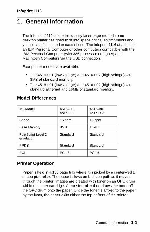
The Infoprint 1116 is a letter–quality laser page monochrome desktop printer designed to fit into space critical environments and yet not sacrifice speed or ease of use. The Infoprint 1116 attaches to an IBM Personal Computer or other computers compatible with the IBM Personal Computer (with 386 processor or higher) and Macintosh Computers via the USB connection.
Four printer models are available:
• The 4516-001 (low voltage) and 4516-002 (high voltage) with 8MB of standard memory.
• The 4516-n01 (low voltage) and 4516-n02 (high voltage) with standard Ethernet and 16MB of standard memory.
Model Differences
Printer Operation
Paper is held in a 150 page tray where it is picked by a center–fed D shape pick roller. The paper follows an L shape path as it moves through the printer. Images are created with toner on an OPC drum within the toner cartridge. A transfer roller then draws the toner off the OPC drum onto the paper. Once the toner is affixed to the paper by the fuser, the paper exits either the top or front of the printer.
MT/Model 4516–0014516-002
4516–n014516-n02
Speed 16 ppm 16 ppm
Base Memory 8MB 16MB
PostScript Level 2emulation
Standard Standard
PPDS Standard Standard
PCL PCL 6 PCL 6
General Information 1-1
Infoprint 1116
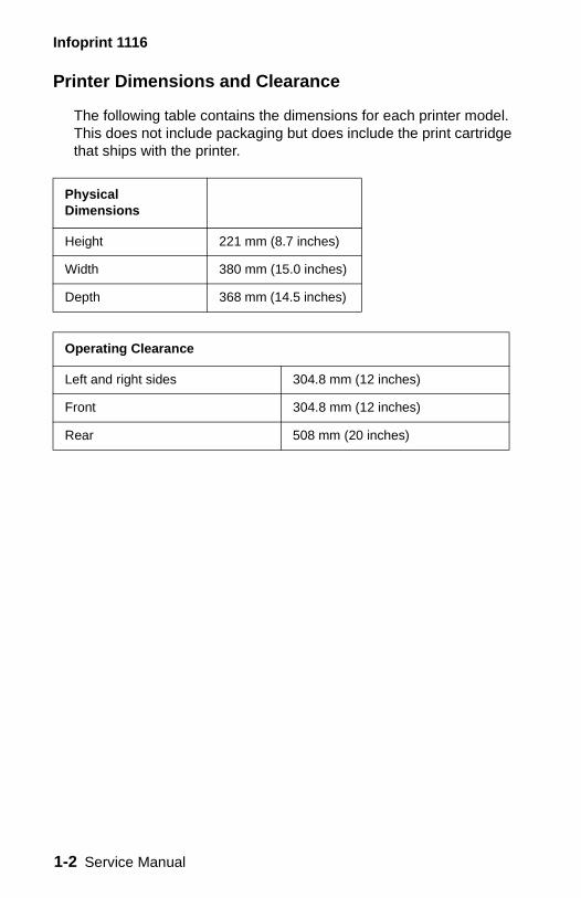
Printer Dimensions and Clearance
The following table contains the dimensions for each printer model. This does not include packaging but does include the print cartridge that ships with the printer.
Physical Dimensions
Height 221 mm (8.7 inches)
Width 380 mm (15.0 inches)
Depth 368 mm (14.5 inches)
Operating Clearance
Left and right sides 304.8 mm (12 inches)
Front 304.8 mm (12 inches)
Rear 508 mm (20 inches)
1-2 Service Manual
Infoprint 1116
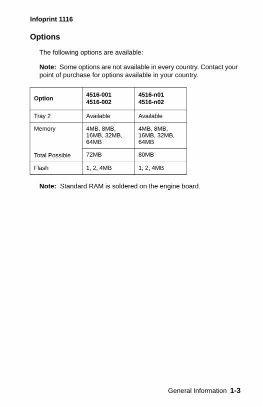
Options
The following options are available:
Note: Some options are not available in every country. Contact your point of purchase for options available in your country.
Note: Standard RAM is soldered on the engine board.
Option4516-0014516-002
4516-n014516-n02
Tray 2 Available Available
Memory
Total Possible
4MB, 8MB, 16MB, 32MB, 64MB
4MB, 8MB, 16MB, 32MB, 64MB
72MB 80MB
Flash 1, 2, 4MB 1, 2, 4MB
General Information 1-3
Infoprint 1116
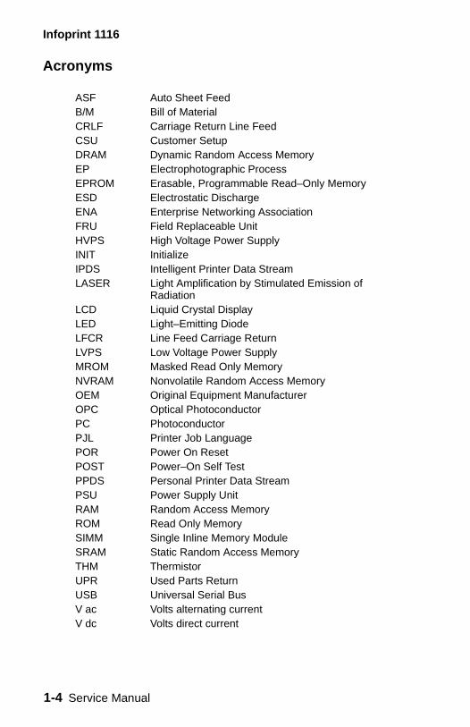
Acronyms
ASF Auto Sheet FeedB/M Bill of Material CRLF Carriage Return Line Feed CSU Customer SetupDRAM Dynamic Random Access MemoryEP Electrophotographic ProcessEPROM Erasable, Programmable Read–Only MemoryESD Electrostatic DischargeENA Enterprise Networking Association FRU Field Replaceable UnitHVPS High Voltage Power SupplyINIT Initialize IPDS Intelligent Printer Data Stream LASER Light Amplification by Stimulated Emission of
RadiationLCD Liquid Crystal DisplayLED Light–Emitting DiodeLFCR Line Feed Carriage Return LVPS Low Voltage Power SupplyMROM Masked Read Only MemoryNVRAM Nonvolatile Random Access MemoryOEM Original Equipment ManufacturerOPC Optical PhotoconductorPC PhotoconductorPJL Printer Job LanguagePOR Power On Reset POST Power–On Self TestPPDS Personal Printer Data Stream PSU Power Supply UnitRAM Random Access Memory ROM Read Only MemorySIMM Single Inline Memory ModuleSRAM Static Random Access MemoryTHM ThermistorUPR Used Parts ReturnUSB Universal Serial BusV ac Volts alternating currentV dc Volts direct current
1-4 Service Manual
Infoprint 1116
2. Diagnostic Information
CAUTION: NEVER manually actuate or disable the top cover interlock switch and the printhead shutter actuator at the same time.
To perform some of the service checks and tests, such as troubleshooting paper feed problems, you need to actuate the top cover interlock switch with the covers open or removed and power applied to the machine. It is important for personal safety that you DO NOT, FOR ANY REASON, disable the printhead shutter actuator when power is on.
Remove power from the printer before you connect or disconnect any cable or electronic board or assembly for personal safety and to prevent damage to the printer.
Use the service error code, user error message, symptom table, service checks, and diagnostic aids in this chapter to determine the corrective action necessary to repair a malfunctioning printer.
The LEDs on the operator panel can indicate either a user error message or service error message. When a service error occurs, the printer stops printing and all operator panel LEDs blink in a continuous pattern, indicating a service error, until the printer is powered off. If all operator panel LEDs are blinking, go to the “Service Error Codes” on page 2-11 for more information.
When a user error message occurs, one or more operator panel LEDs are on solid or blinking. See the “Status Information” on page 2-3 for more information.
If your machine does not have a service error code and does not complete POST, go to the “POST Symptom Table” on page 2-36. If your machine completes POST without an error, and you have a symptom, go to the “Printer Symptom Table” on page 2-37. Locate your symptom and take the appropriate action.
If a service error code appears while you are working on the machine, go to the “Service Error Codes” on page 2-11 and take the indicated action for that error.
Diagnostic Information 2-1
Infoprint 1116
Operator Panel
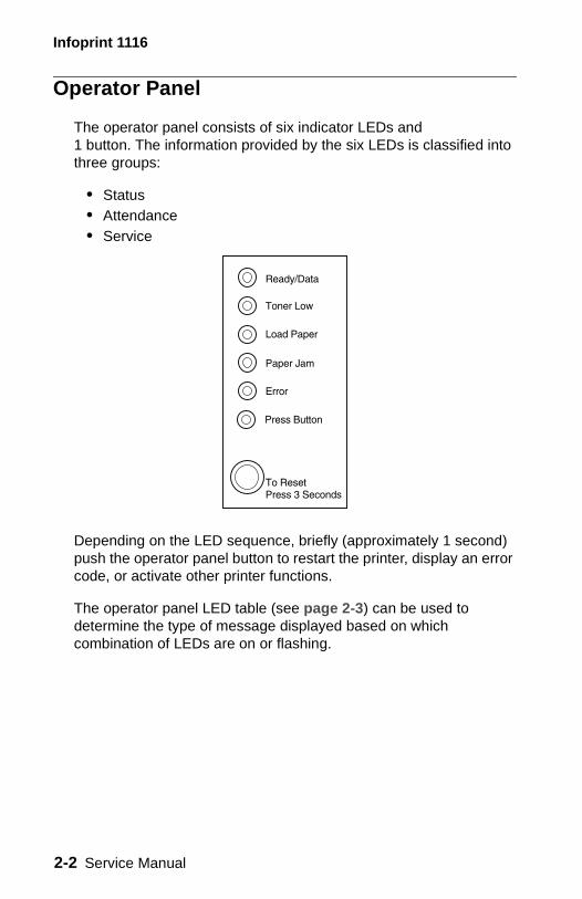
The operator panel consists of six indicator LEDs and 1 button. The information provided by the six LEDs is classified into three groups:
• Status • Attendance • Service
Depending on the LED sequence, briefly (approximately 1 second) push the operator panel button to restart the printer, display an error code, or activate other printer functions.
The operator panel LED table (see page 2-3) can be used to determine the type of message displayed based on which combination of LEDs are on or flashing.
2-2 Service Manual
Infoprint 1116
Status Information
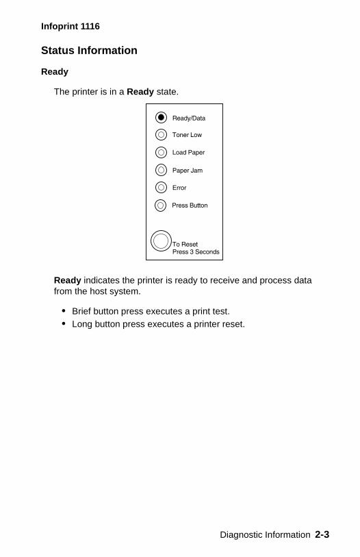
Ready
The printer is in a Ready state.
Ready indicates the printer is ready to receive and process data from the host system.
• Brief button press executes a print test.• Long button press executes a printer reset.
Diagnostic Information 2-3
Infoprint 1116
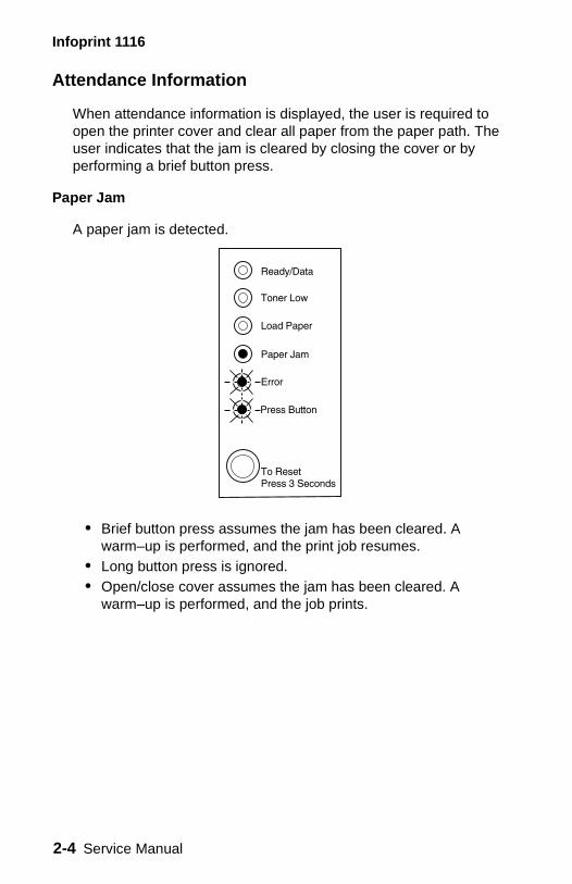
Attendance Information
When attendance information is displayed, the user is required to open the printer cover and clear all paper from the paper path. The user indicates that the jam is cleared by closing the cover or by performing a brief button press.
Paper Jam
A paper jam is detected.
• Brief button press assumes the jam has been cleared. A warm–up is performed, and the print job resumes.
• Long button press is ignored. • Open/close cover assumes the jam has been cleared. A
warm–up is performed, and the job prints.
2-4 Service Manual
Infoprint 1116
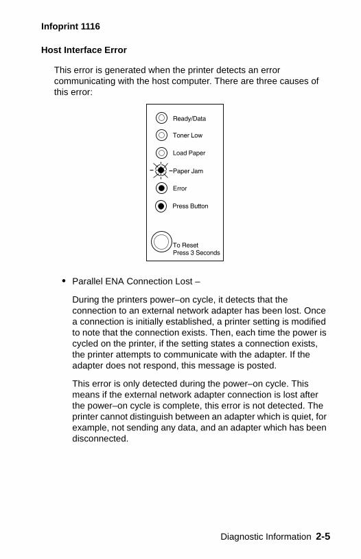
Host Interface Error
This error is generated when the printer detects an error communicating with the host computer. There are three causes of this error:
• Parallel ENA Connection Lost –
During the printers power–on cycle, it detects that the connection to an external network adapter has been lost. Once a connection is initially established, a printer setting is modified to note that the connection exists. Then, each time the power is cycled on the printer, if the setting states a connection exists, the printer attempts to communicate with the adapter. If the adapter does not respond, this message is posted.
This error is only detected during the power–on cycle. This means if the external network adapter connection is lost after the power–on cycle is complete, this error is not detected. The printer cannot distinguish between an adapter which is quiet, for example, not sending any data, and an adapter which has been disconnected.
Diagnostic Information 2-5
Infoprint 1116
• Standard Parallel Port Disabled –
This error is generated when the host computer attempts to communicate with the printer through the standard parallel port, but the parallel port has been disabled either through the printer configuration mode, or through the MarkVision™ host utility.
• Standard USB Port Disabled –
This error is generated when the host computer attempts to communicate with the printer through the standard USB port, but the USB port has been disabled either through the printer configuration mode, or through the MarkVision host utility.
The error recovery process for this error is:
1. If this error occurs at power–on and an ENA is attached to the printer, verify the ENA is properly connected.
2. When the printer is in the Ready state, press the operator panel button to print a menus settings page.
3. Under the “parallel menu”, look for the “parallel buffer” line. If this line says “disabled” and the host computer is trying to print using the parallel port, re–enable the parallel port using MarkVision or the printers configuration mode.
4. Under the “USB menu”, look for the “USB buffer” line. If this line says “disabled” and the host computer is trying to print using the USB port, re–enable the USB port using MarkVision or the printer configuration mode.
See “Configuration Mode” on page 3-14 for information on using the printer configuration mode to enable a disabled port.
2-6 Service Manual
Infoprint 1116
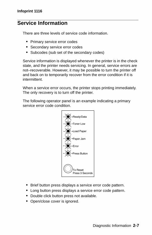
Service Information
There are three levels of service code information.
• Primary service error codes • Secondary service error codes • Subcodes (sub set of the secondary codes)
Service information is displayed whenever the printer is in the check state, and the printer needs servicing. In general, service errors are not–recoverable. However, it may be possible to turn the printer off and back on to temporarily recover from the error condition if it is intermittent.
When a service error occurs, the printer stops printing immediately. The only recovery is to turn off the printer.
The following operator panel is an example indicating a primary service error code condition.
• Brief button press displays a service error code pattern. • Long button press displays a service error code pattern. • Double click button press not available. • Open/close cover is ignored.
Diagnostic Information 2-7
Infoprint 1116
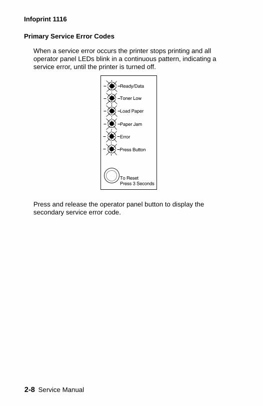
Primary Service Error Codes
When a service error occurs the printer stops printing and all operator panel LEDs blink in a continuous pattern, indicating a service error, until the printer is turned off.
Press and release the operator panel button to display the secondary service error code.
2-8 Service Manual
Infoprint 1116
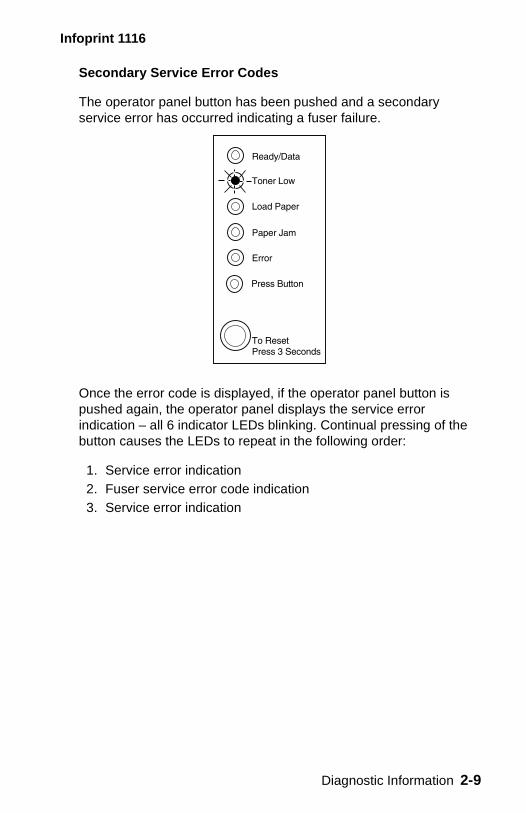
Secondary Service Error Codes
The operator panel button has been pushed and a secondary service error has occurred indicating a fuser failure.
Once the error code is displayed, if the operator panel button is pushed again, the operator panel displays the service error indication – all 6 indicator LEDs blinking. Continual pressing of the button causes the LEDs to repeat in the following order:
1. Service error indication2. Fuser service error code indication3. Service error indication
Diagnostic Information 2-9
Infoprint 1116
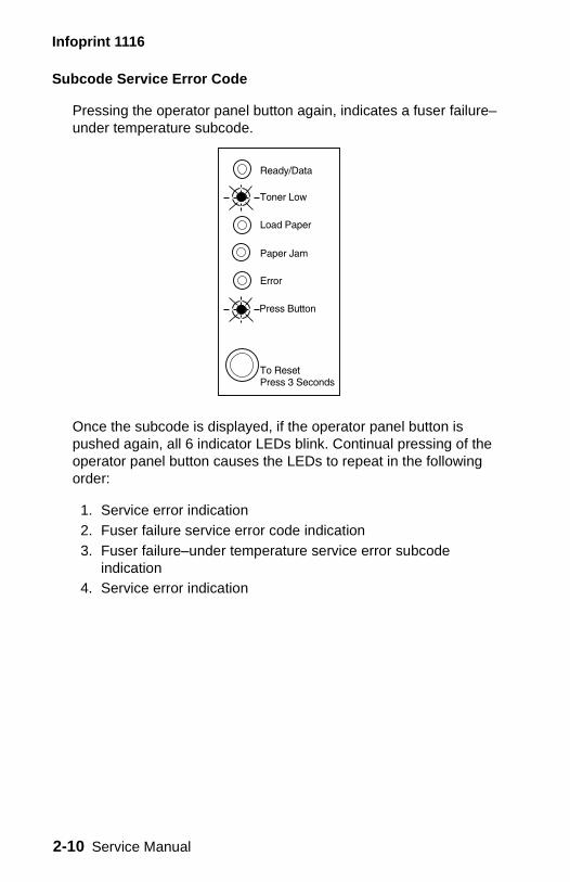
Subcode Service Error Code
Pressing the operator panel button again, indicates a fuser failure– under temperature subcode.
Once the subcode is displayed, if the operator panel button is pushed again, all 6 indicator LEDs blink. Continual pressing of the operator panel button causes the LEDs to repeat in the following order:
1. Service error indication2. Fuser failure service error code indication3. Fuser failure–under temperature service error subcode
indication4. Service error indication
2-10 Service Manual
Infoprint 1116
Service Error Codes
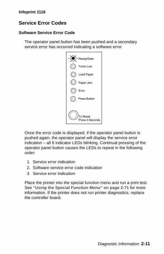
Software Service Error Code
The operator panel button has been pushed and a secondary service error has occurred indicating a software error.
Once the error code is displayed, if the operator panel button is pushed again, the operator panel will display the service error indication – all 6 indicator LEDs blinking. Continual pressing of the operator panel button causes the LEDs to repeat in the following order:
1. Service error indication2. Software service error code indication3. Service error indication
Place the printer into the special function menu and run a print test. See “Using the Special Function Menu” on page 2-71 for more information. If the printer does not run printer diagnostics, replace the controller board.
Diagnostic Information 2-11
Infoprint 1116
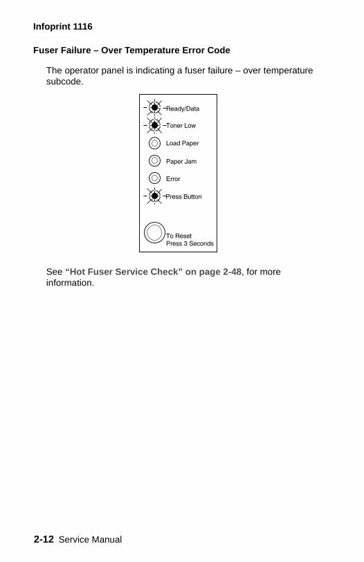
Fuser Failure – Over Temperature Error Code
The operator panel is indicating a fuser failure – over temperature subcode.
See “Hot Fuser Service Check” on page 2-48, for more information.
2-12 Service Manual
Infoprint 1116
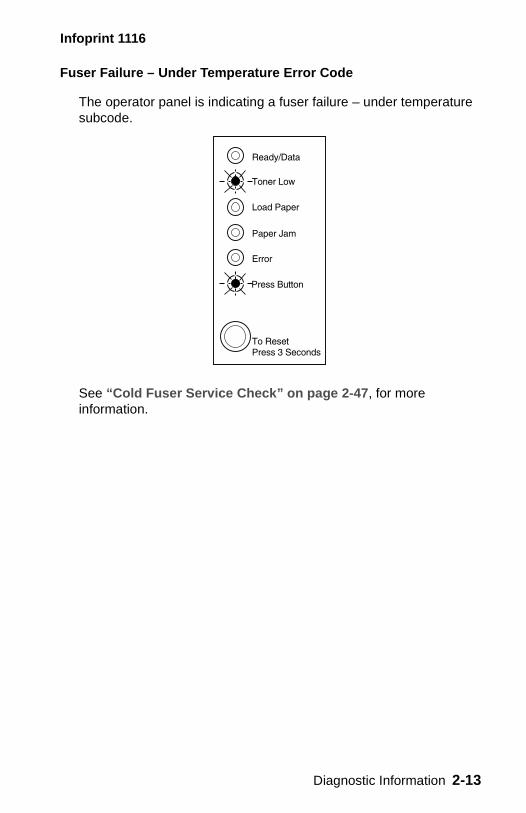
Fuser Failure – Under Temperature Error Code
The operator panel is indicating a fuser failure – under temperature subcode.
See “Cold Fuser Service Check” on page 2-47, for more information.
Diagnostic Information 2-13
Infoprint 1116
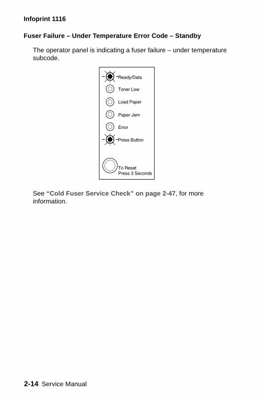
Fuser Failure – Under Temperature Error Code – Standby
The operator panel is indicating a fuser failure – under temperature subcode.
See “Cold Fuser Service Check” on page 2-47, for more information.
2-14 Service Manual
Infoprint 1116
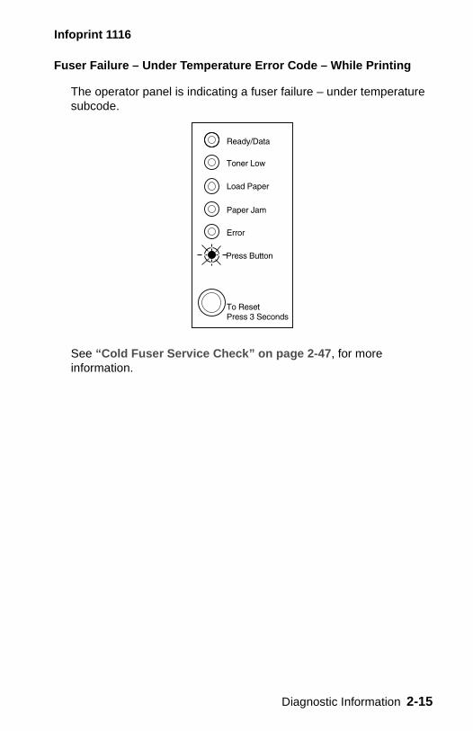
Fuser Failure – Under Temperature Error Code – While Printing
The operator panel is indicating a fuser failure – under temperature subcode.
See “Cold Fuser Service Check” on page 2-47, for more information.
Diagnostic Information 2-15
Infoprint 1116
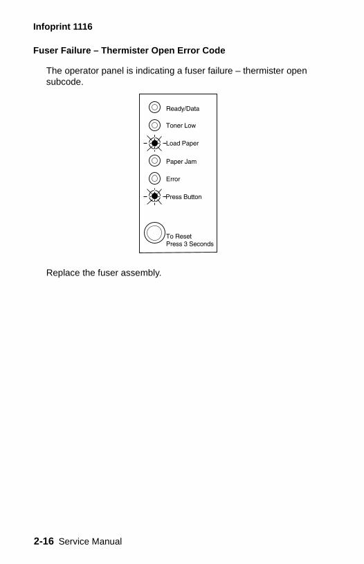
Fuser Failure – Thermister Open Error Code
The operator panel is indicating a fuser failure – thermister open subcode.
Replace the fuser assembly.
2-16 Service Manual

Infoprint 1116
Mirror Motor Failure Service Error Code
The operator panel button has been pushed and a mirror motor failure service error has occurred.
Once the error code is displayed, if the operator panel button is pushed again, the operator panel displays the service error indication – all 6 indicator LEDs blinking. Continual pressing of the operator panel button causes the LEDs to repeat in the following order:
1. Service error indication2. Mirror motor failure service error code indication3. Service error indication
Inspect the printhead cable and replace the assembly as necessary. If this does not correct the problem, replace the engine/LVPS board.
Diagnostic Information 2-17
Infoprint 1116
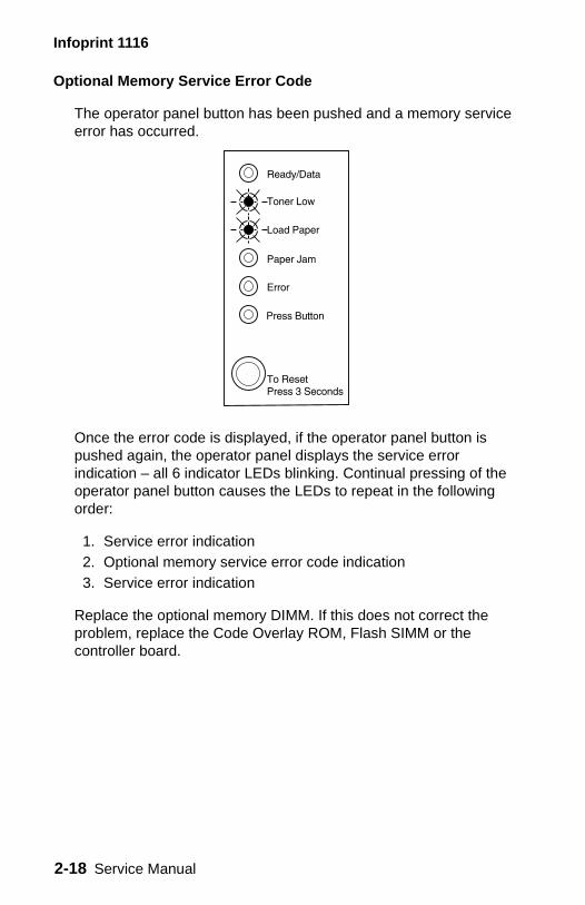
Optional Memory Service Error Code
The operator panel button has been pushed and a memory service error has occurred.
Once the error code is displayed, if the operator panel button is pushed again, the operator panel displays the service error indication – all 6 indicator LEDs blinking. Continual pressing of the operator panel button causes the LEDs to repeat in the following order:
1. Service error indication2. Optional memory service error code indication3. Service error indication
Replace the optional memory DIMM. If this does not correct the problem, replace the Code Overlay ROM, Flash SIMM or the controller board.
2-18 Service Manual
Infoprint 1116
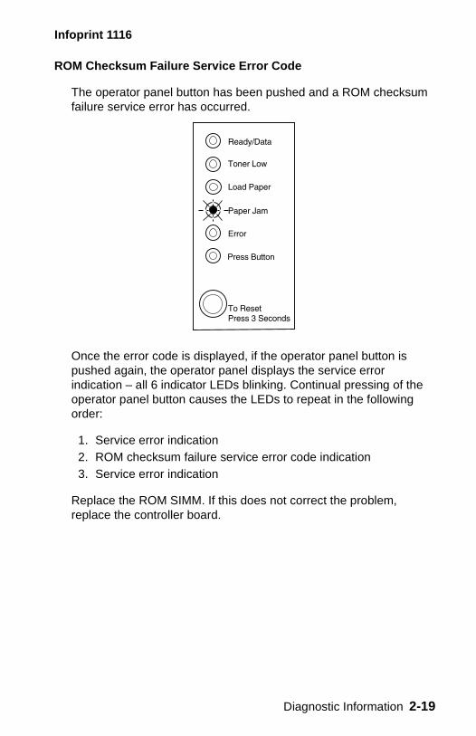
ROM Checksum Failure Service Error Code
The operator panel button has been pushed and a ROM checksum failure service error has occurred.
Once the error code is displayed, if the operator panel button is pushed again, the operator panel displays the service error indication – all 6 indicator LEDs blinking. Continual pressing of the operator panel button causes the LEDs to repeat in the following order:
1. Service error indication2. ROM checksum failure service error code indication3. Service error indication
Replace the ROM SIMM. If this does not correct the problem, replace the controller board.
Diagnostic Information 2-19
Infoprint 1116
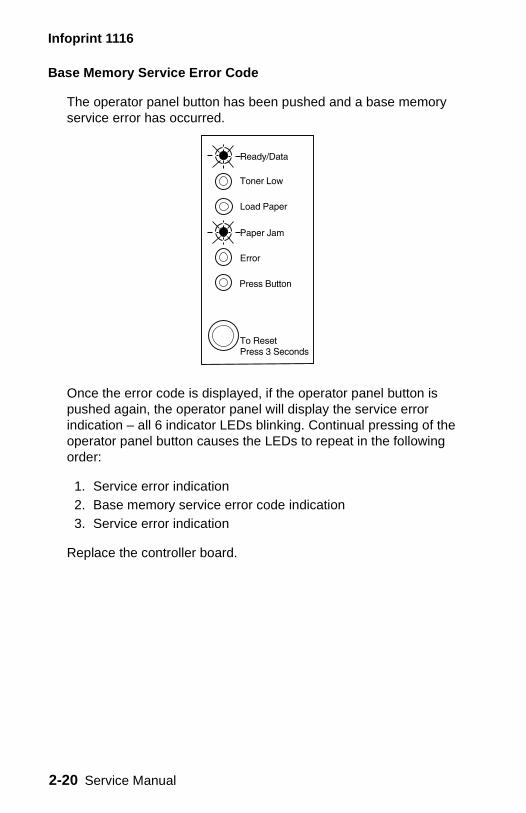
Base Memory Service Error Code
The operator panel button has been pushed and a base memory service error has occurred.
Once the error code is displayed, if the operator panel button is pushed again, the operator panel will display the service error indication – all 6 indicator LEDs blinking. Continual pressing of the operator panel button causes the LEDs to repeat in the following order:
1. Service error indication2. Base memory service error code indication3. Service error indication
Replace the controller board.
2-20 Service Manual
Infoprint 1116
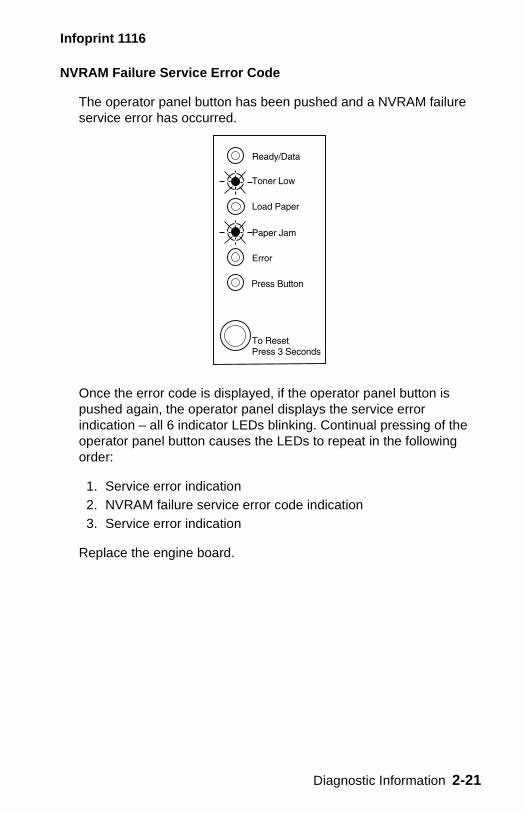
NVRAM Failure Service Error Code
The operator panel button has been pushed and a NVRAM failure service error has occurred.
Once the error code is displayed, if the operator panel button is pushed again, the operator panel displays the service error indication – all 6 indicator LEDs blinking. Continual pressing of the operator panel button causes the LEDs to repeat in the following order:
1. Service error indication2. NVRAM failure service error code indication3. Service error indication
Replace the engine board.
Diagnostic Information 2-21
Infoprint 1116
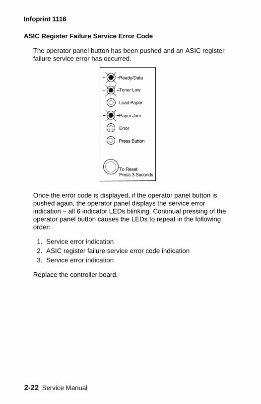
ASIC Register Failure Service Error Code
The operator panel button has been pushed and an ASIC register failure service error has occurred.
Once the error code is displayed, if the operator panel button is pushed again, the operator panel displays the service error indication – all 6 indicator LEDs blinking. Continual pressing of the operator panel button causes the LEDs to repeat in the following order:
1. Service error indication2. ASIC register failure service error code indication3. Service error indication
Replace the controller board.
2-22 Service Manual
Infoprint 1116
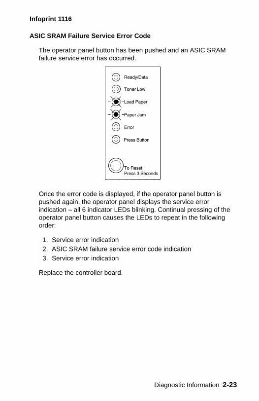
ASIC SRAM Failure Service Error Code
The operator panel button has been pushed and an ASIC SRAM failure service error has occurred.
Once the error code is displayed, if the operator panel button is pushed again, the operator panel displays the service error indication – all 6 indicator LEDs blinking. Continual pressing of the operator panel button causes the LEDs to repeat in the following order:
1. Service error indication2. ASIC SRAM failure service error code indication3. Service error indication
Replace the controller board.
Diagnostic Information 2-23
Infoprint 1116
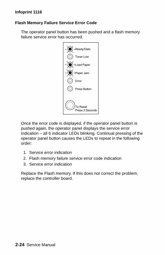
Flash Memory Failure Service Error Code
The operator panel button has been pushed and a flash memory failure service error has occurred.
Once the error code is displayed, if the operator panel button is pushed again, the operator panel displays the service error indication – all 6 indicator LEDs blinking. Continual pressing of the operator panel button causes the LEDs to repeat in the following order:
1. Service error indication2. Flash memory failure service error code indication3. Service error indication
Replace the Flash memory. If this does not correct the problem, replace the controller board.
2-24 Service Manual
Infoprint 1116
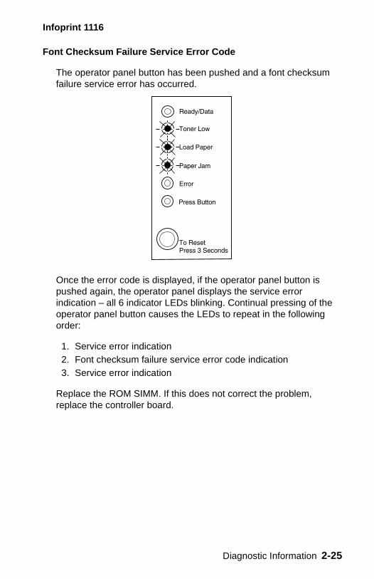
Font Checksum Failure Service Error Code
The operator panel button has been pushed and a font checksum failure service error has occurred.
Once the error code is displayed, if the operator panel button is pushed again, the operator panel displays the service error indication – all 6 indicator LEDs blinking. Continual pressing of the operator panel button causes the LEDs to repeat in the following order:
1. Service error indication2. Font checksum failure service error code indication3. Service error indication
Replace the ROM SIMM. If this does not correct the problem, replace the controller board.
Diagnostic Information 2-25
Infoprint 1116
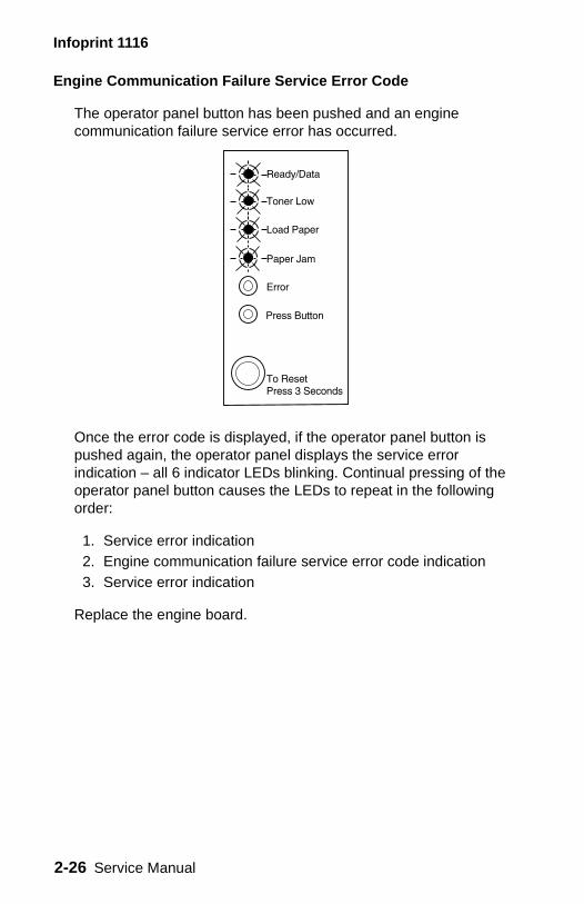
Engine Communication Failure Service Error Code
The operator panel button has been pushed and an engine communication failure service error has occurred.
Once the error code is displayed, if the operator panel button is pushed again, the operator panel displays the service error indication – all 6 indicator LEDs blinking. Continual pressing of the operator panel button causes the LEDs to repeat in the following order:
1. Service error indication2. Engine communication failure service error code indication3. Service error indication
Replace the engine board.
2-26 Service Manual

Infoprint 1116
Error Codes/Conditions Not Detected or Reported
The printer does not detect or report the following conditions/errors:
• Incorrect manual feed• Output bin full• Print cartridge missing (reported as “top cover open” error)
Diagnostic Information 2-27
Infoprint 1116
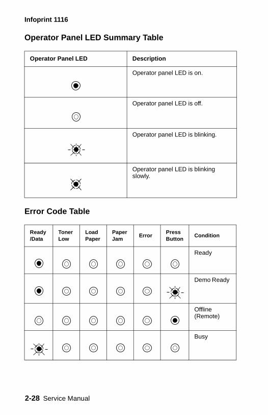
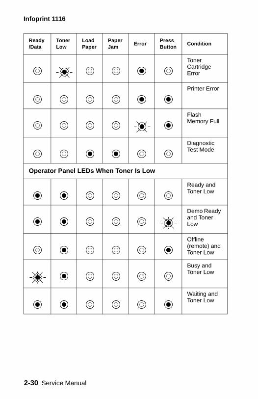
Operator Panel LED Summary Table
Error Code Table
Operator Panel LED Description
Operator panel LED is on.
Operator panel LED is off.
Operator panel LED is blinking.
Operator panel LED is blinking slowly.
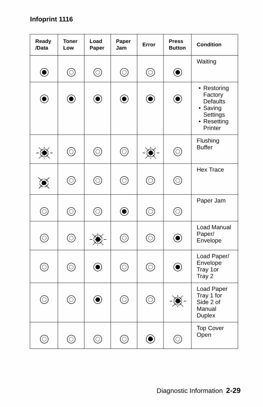
Ready/Data
Toner Low
Load Paper
Paper Jam
ErrorPress Button
Condition
Ready
Demo Ready
Offline (Remote)
Busy
2-28 Service Manual
Infoprint 1116
Waiting
• Restoring Factory Defaults
• Saving Settings
• Resetting Printer
Flushing Buffer
Hex Trace
Paper Jam
Load Manual Paper/Envelope
Load Paper/Envelope Tray 1or Tray 2
Load Paper Tray 1 for Side 2 of Manual Duplex
Top Cover Open
Ready/Data
Toner Low
Load Paper
Paper Jam
ErrorPress Button
Condition
Diagnostic Information 2-29
Infoprint 1116
Toner Cartridge Error
Printer Error
Flash Memory Full
Diagnostic Test Mode
Operator Panel LEDs When Toner Is Low
Ready and Toner Low
Demo Ready and Toner Low
Offline (remote) and Toner Low
Busy and Toner Low
Waiting and Toner Low
Ready/Data
Toner Low
Load Paper
Paper Jam
ErrorPress Button
Condition
2-30 Service Manual
Infoprint 1116
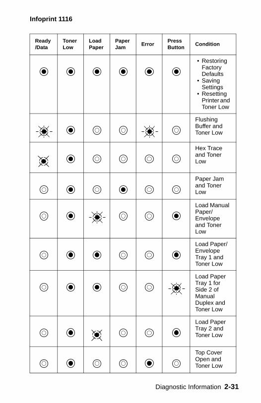
• Restoring Factory Defaults
• Saving Settings
• Resetting Printer and Toner Low
Flushing Buffer and Toner Low
Hex Trace and Toner Low
Paper Jam and Toner Low
Load Manual Paper/Envelope and Toner Low
Load Paper/Envelope Tray 1 and Toner Low
Load Paper Tray 1 for Side 2 of Manual Duplex and Toner Low
Load Paper Tray 2 and Toner Low
Top Cover Open and Toner Low
Ready/Data
Toner Low
Load Paper
Paper Jam
ErrorPress Button
Condition
Diagnostic Information 2-31
Infoprint 1116
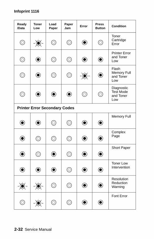
Toner Cartridge Error
Printer Error and Toner Low
Flash Memory Full and Toner Low
Diagnostic Test Mode and Toner Low
Printer Error Secondary Codes
Memory Full
Complex Page
Short Paper
Toner Low Intervention
Resolution Reduction Warning
Font Error
Ready/Data
Toner Low
Load Paper
Paper Jam
ErrorPress Button
Condition
2-32 Service Manual
Infoprint 1116
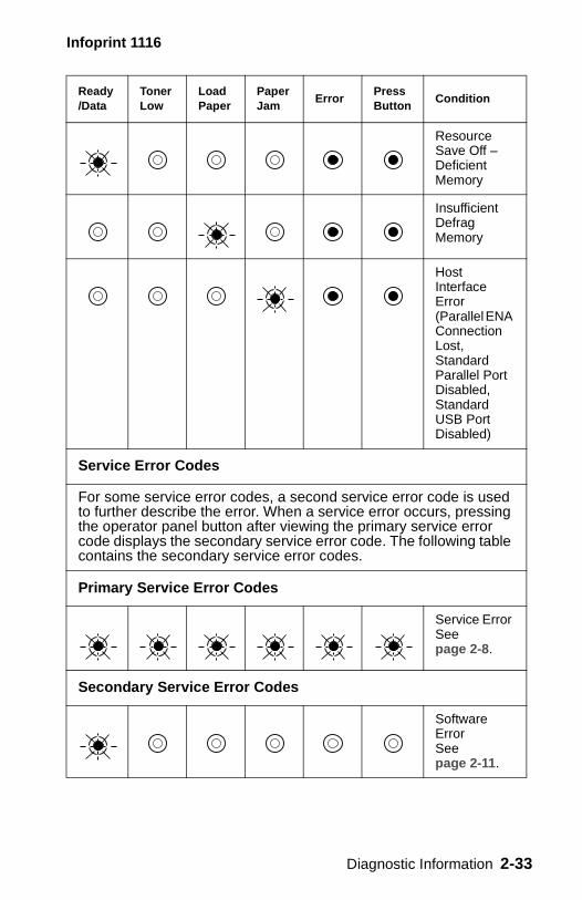
Resource Save Off – Deficient Memory
Insufficient Defrag Memory
Host Interface Error (Parallel ENA Connection Lost, Standard Parallel Port Disabled, Standard USB Port Disabled)
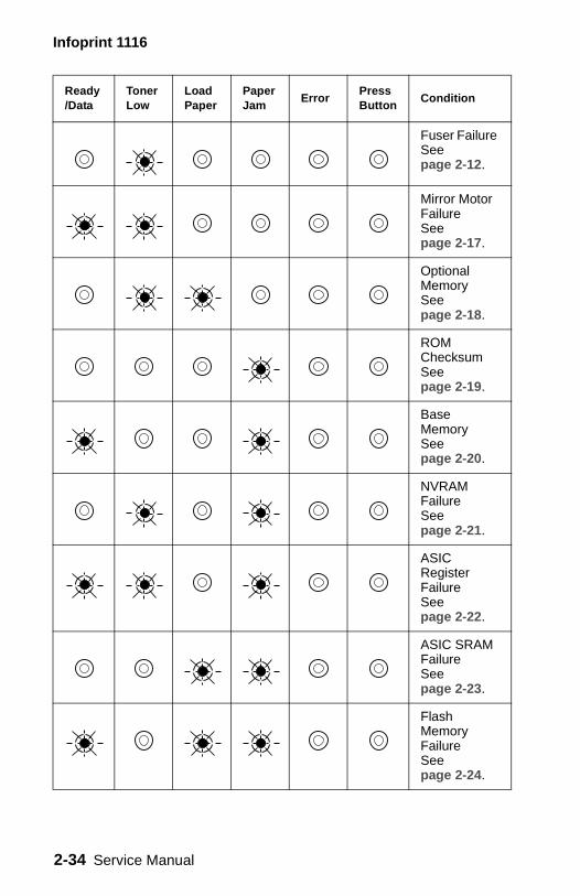
Service Error Codes
For some service error codes, a second service error code is used to further describe the error. When a service error occurs, pressing the operator panel button after viewing the primary service error code displays the secondary service error code. The following table contains the secondary service error codes.
Primary Service Error Codes
Service Error See page 2-8.
Secondary Service Error Codes
Software Error See page 2-11.
Ready/Data
Toner Low
Load Paper
Paper Jam
ErrorPress Button
Condition
Diagnostic Information 2-33
Infoprint 1116
Fuser Failure See page 2-12.
Mirror Motor Failure See page 2-17.
Optional Memory See page 2-18.
ROM Checksum See page 2-19.
Base Memory See page 2-20.
NVRAM Failure See page 2-21.
ASIC Register FailureSee page 2-22.
ASIC SRAM Failure See page 2-23.
Flash Memory FailureSee page 2-24.
Ready/Data
Toner Low
Load Paper
Paper Jam
ErrorPress Button
Condition
2-34 Service Manual
Infoprint 1116
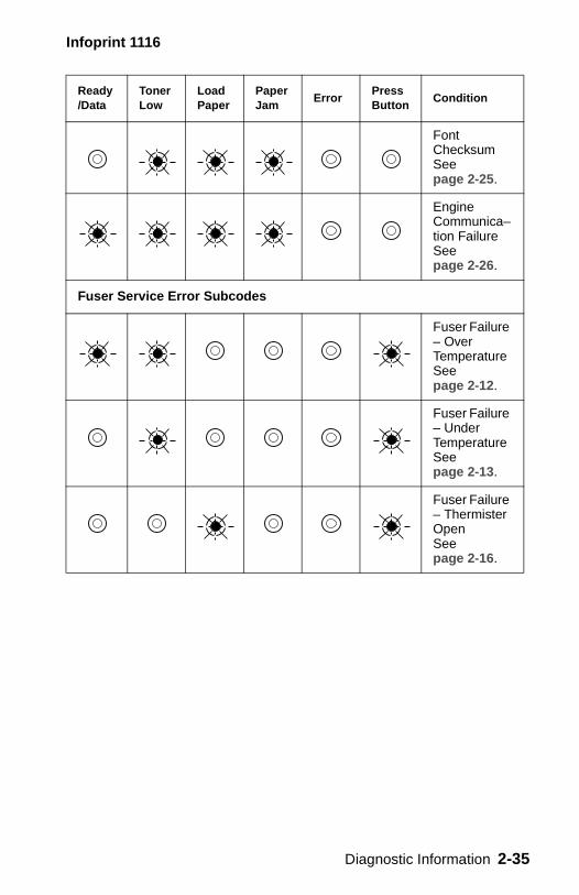
Font Checksum See page 2-25.
Engine Communica–tion Failure See page 2-26.
Fuser Service Error Subcodes
Fuser Failure – Over Temperature See page 2-12.
Fuser Failure – Under Temperature See page 2-13.
Fuser Failure – Thermister Open See page 2-16.
Ready/Data
Toner Low
Load Paper
Paper Jam
ErrorPress Button
Condition
Diagnostic Information 2-35
Infoprint 1116
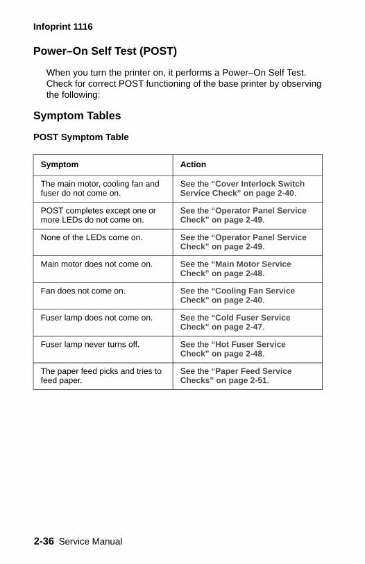
Power–On Self Test (POST)
When you turn the printer on, it performs a Power–On Self Test. Check for correct POST functioning of the base printer by observing the following:
Symptom Tables
POST Symptom Table
Symptom Action
The main motor, cooling fan and fuser do not come on.
See the “Cover Interlock Switch Service Check” on page 2-40.
POST completes except one or more LEDs do not come on.
See the “Operator Panel Service Check” on page 2-49.
None of the LEDs come on. See the “Operator Panel Service Check” on page 2-49.
Main motor does not come on. See the “Main Motor Service Check” on page 2-48.
Fan does not come on. See the “Cooling Fan Service Check” on page 2-40.
Fuser lamp does not come on. See the “Cold Fuser Service Check” on page 2-47.
Fuser lamp never turns off. See the “Hot Fuser Service Check” on page 2-48.
The paper feed picks and tries to feed paper.
See the “Paper Feed Service Checks” on page 2-51.
2-36 Service Manual
Infoprint 1116
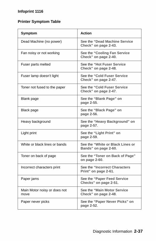
Printer Symptom Table
Symptom Action
Dead Machine (no power) See the “Dead Machine Service Check” on page 2-43.
Fan noisy or not working See the “Cooling Fan Service Check” on page 2-40.
Fuser parts melted See the “Hot Fuser Service Check” on page 2-48.
Fuser lamp doesn’t light See the “Cold Fuser Service Check” on page 2-47.
Toner not fused to the paper See the “Cold Fuser Service Check” on page 2-47.
Blank page See the “Blank Page” on page 2-55.
Black page See the “Black Page” on page 2-56.
Heavy background See the “Heavy Background” on page 2-57.
Light print See the “Light Print” on page 2-59.
White or black lines or bands See the “White or Black Lines or Bands” on page 2-60.
Toner on back of page See the “Toner on Back of Page” on page 2-60.
Incorrect characters print See the “Incorrect Characters Print” on page 2-61.
Paper jams See the “Paper Feed Service Checks” on page 2-51.
Main Motor noisy or does not move
See the “Main Motor Service Check” on page 2-48.
Paper never picks See the “Paper Never Picks” on page 2-52.
Diagnostic Information 2-37
Infoprint 1116
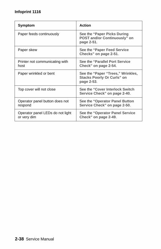
Paper feeds continuously See the “Paper Picks During POST and/or Continuously” on page 2-51.
Paper skew See the “Paper Feed Service Checks” on page 2-51.
Printer not communicating with host
See the “Parallel Port Service Check” on page 2-54.
Paper wrinkled or bent See the “Paper “Trees,” Wrinkles, Stacks Poorly Or Curls” on page 2-53.
Top cover will not close See the “Cover Interlock Switch Service Check” on page 2-40.
Operator panel button does not respond
See the “Operator Panel Button Service Check” on page 2-50.
Operator panel LEDs do not light or very dim
See the “Operator Panel Service Check” on page 2-49.
Symptom Action
2-38 Service Manual

Infoprint 1116
Service Checks
Service checks which involve measuring voltages of the LVPS/engine boards must be performed with the printer positioned on its back side. This provides the servicer access to the circuit boards underneath the printer while supplying necessary power to the rest of the printer.
Diagnostic Information 2-39
Infoprint 1116
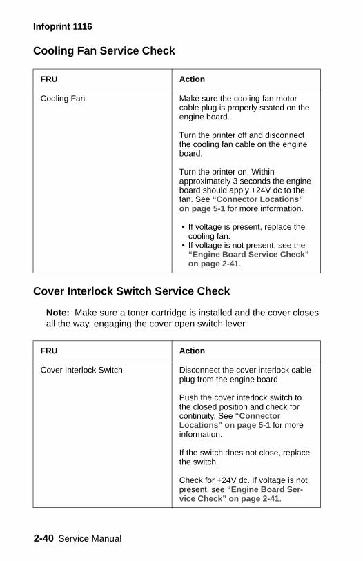
Cooling Fan Service Check
Cover Interlock Switch Service Check
Note: Make sure a toner cartridge is installed and the cover closes all the way, engaging the cover open switch lever.
FRU Action
Cooling Fan Make sure the cooling fan motor cable plug is properly seated on the engine board.
Turn the printer off and disconnect the cooling fan cable on the engine board.
Turn the printer on. Within approximately 3 seconds the engine board should apply +24V dc to the fan. See “Connector Locations” on page 5-1 for more information.
• If voltage is present, replace the cooling fan.
• If voltage is not present, see the “Engine Board Service Check” on page 2-41.
FRU Action
Cover Interlock Switch Disconnect the cover interlock cable plug from the engine board.
Push the cover interlock switch to the closed position and check for continuity. See “Connector Locations” on page 5-1 for more information.
If the switch does not close, replace the switch.
Check for +24V dc. If voltage is not present, see “Engine Board Ser-vice Check” on page 2-41.
2-40 Service Manual
Infoprint 1116
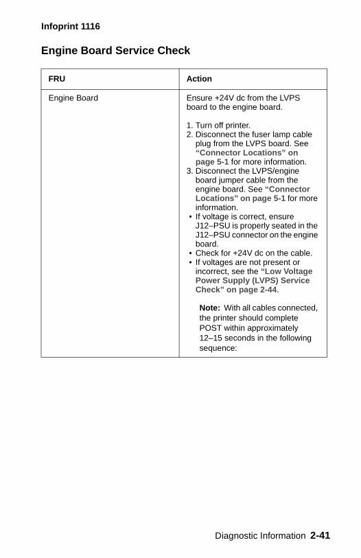
Engine Board Service Check
FRU Action
Engine Board Ensure +24V dc from the LVPS board to the engine board.
1. Turn off printer. 2. Disconnect the fuser lamp cable
plug from the LVPS board. See “Connector Locations” on page 5-1 for more information.
3. Disconnect the LVPS/engine board jumper cable from the engine board. See “Connector Locations” on page 5-1 for more information.
• If voltage is correct, ensure J12–PSU is properly seated in the J12–PSU connector on the engine board.
• Check for +24V dc on the cable. • If voltages are not present or
incorrect, see the “Low Voltage Power Supply (LVPS) Service Check” on page 2-44.
Note: With all cables connected, the printer should complete POST within approximately 12–15 seconds in the following sequence:
Diagnostic Information 2-41
Infoprint 1116
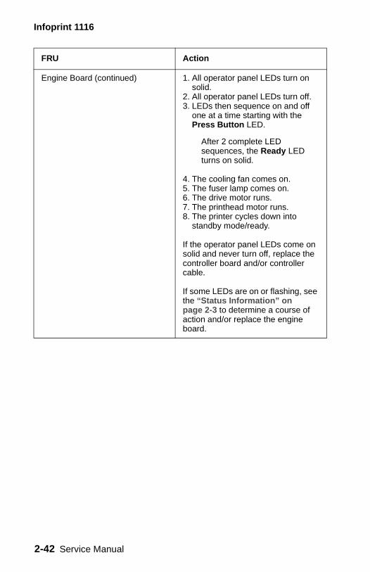
Engine Board (continued) 1. All operator panel LEDs turn on solid.
2. All operator panel LEDs turn off. 3. LEDs then sequence on and off
one at a time starting with the Press Button LED.
After 2 complete LED sequences, the Ready LED turns on solid.
4. The cooling fan comes on. 5. The fuser lamp comes on. 6. The drive motor runs. 7. The printhead motor runs. 8. The printer cycles down into
standby mode/ready.
If the operator panel LEDs come on solid and never turn off, replace the controller board and/or controller cable.
If some LEDs are on or flashing, see the “Status Information” on page 2-3 to determine a course of action and/or replace the engine board.
FRU Action
2-42 Service Manual
Infoprint 1116
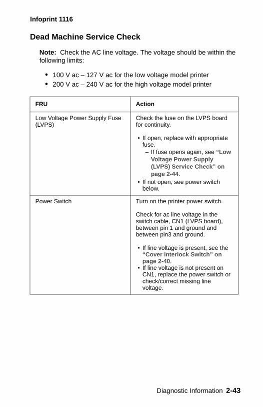
Dead Machine Service Check
Note: Check the AC line voltage. The voltage should be within the following limits:
• 100 V ac – 127 V ac for the low voltage model printer• 200 V ac – 240 V ac for the high voltage model printer
FRU Action
Low Voltage Power Supply Fuse (LVPS)
Check the fuse on the LVPS board for continuity.
• If open, replace with appropriate fuse. – If fuse opens again, see “Low
Voltage Power Supply (LVPS) Service Check” on page 2-44.
• If not open, see power switch below.
Power Switch Turn on the printer power switch.
Check for ac line voltage in the switch cable, CN1 (LVPS board), between pin 1 and ground and between pin3 and ground.
• If line voltage is present, see the “Cover Interlock Switch” on page 2-40.
• If line voltage is not present on CN1, replace the power switch or check/correct missing line voltage.
Diagnostic Information 2-43
Infoprint 1116
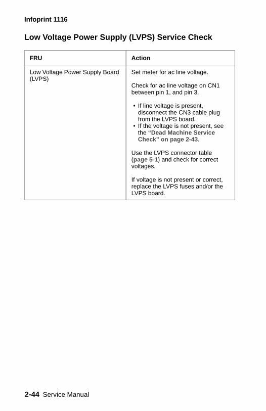
Low Voltage Power Supply (LVPS) Service Check
FRU Action
Low Voltage Power Supply Board (LVPS)
Set meter for ac line voltage.
Check for ac line voltage on CN1 between pin 1, and pin 3.
• If line voltage is present, disconnect the CN3 cable plug from the LVPS board.
• If the voltage is not present, see the “Dead Machine Service Check” on page 2-43.
Use the LVPS connector table (page 5-1) and check for correct voltages.
If voltage is not present or correct, replace the LVPS fuses and/or the LVPS board.
2-44 Service Manual
Infoprint 1116
Fuser Service Check
When toner is partially fused to the paper, it is usually caused by low fuser temperature.
WARNING: Avoid handling the lamp as much as possible as it is easily broken. Be careful not to touch the glass housing with bare hands as skin contains acids that can weaken the glass.
The line voltage to the printer must be within the following limits:
• 100 V ac – 127 V ac for the low voltage model printer• 200 V ac – 240 V ac for the high voltage model printer
Turn the printer off and wait a few minutes for the fuser lamp to cool. Turn the machine on and observe the lamp turning on during POST.
You can see the lamp with the left side cover and fuser wire cover removed.
Diagnostic Information 2-45
Infoprint 1116
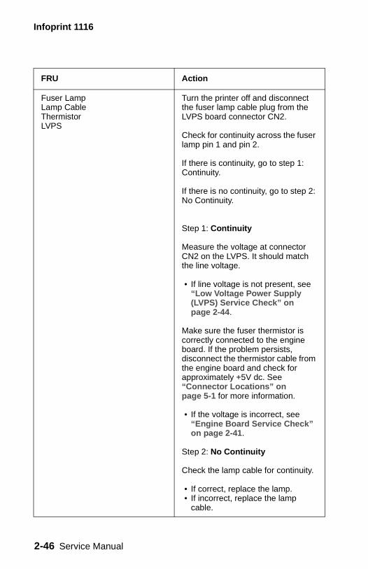
FRU Action
Fuser LampLamp CableThermistorLVPS
Turn the printer off and disconnect the fuser lamp cable plug from the LVPS board connector CN2.
Check for continuity across the fuser lamp pin 1 and pin 2.
If there is continuity, go to step 1: Continuity.
If there is no continuity, go to step 2: No Continuity.
Step 1: Continuity
Measure the voltage at connector CN2 on the LVPS. It should match the line voltage.
• If line voltage is not present, see “Low Voltage Power Supply (LVPS) Service Check” on page 2-44.
Make sure the fuser thermistor is correctly connected to the engine board. If the problem persists, disconnect the thermistor cable from the engine board and check for approximately +5V dc. See “Connector Locations” on page 5-1 for more information.
• If the voltage is incorrect, see “Engine Board Service Check” on page 2-41.
Step 2: No Continuity
Check the lamp cable for continuity.
• If correct, replace the lamp.• If incorrect, replace the lamp
cable.
2-46 Service Manual
Infoprint 1116
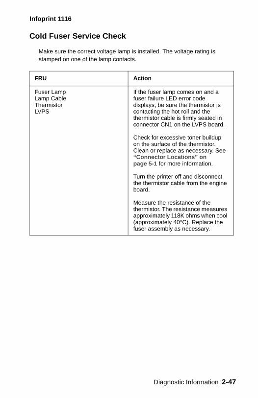
Cold Fuser Service Check
Make sure the correct voltage lamp is installed. The voltage rating is stamped on one of the lamp contacts.
FRU Action
Fuser Lamp Lamp Cable Thermistor LVPS
If the fuser lamp comes on and a fuser failure LED error code displays, be sure the thermistor is contacting the hot roll and the thermistor cable is firmly seated in connector CN1 on the LVPS board.
Check for excessive toner buildup on the surface of the thermistor. Clean or replace as necessary. See “Connector Locations” on page 5-1 for more information.
Turn the printer off and disconnect the thermistor cable from the engine board.
Measure the resistance of the thermistor. The resistance measures approximately 118K ohms when cool (approximately 40°C). Replace the fuser assembly as necessary.
Diagnostic Information 2-47
Infoprint 1116
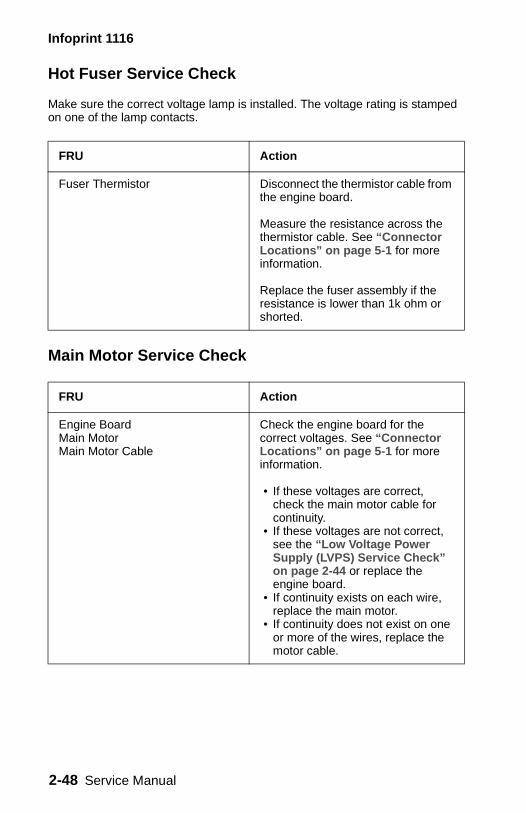
Hot Fuser Service Check
Make sure the correct voltage lamp is installed. The voltage rating is stamped on one of the lamp contacts.
Main Motor Service Check
FRU Action
Fuser Thermistor Disconnect the thermistor cable from the engine board.
Measure the resistance across the thermistor cable. See “Connector Locations” on page 5-1 for more information.
Replace the fuser assembly if the resistance is lower than 1k ohm or shorted.
FRU Action
Engine Board Main Motor Main Motor Cable
Check the engine board for the correct voltages. See “Connector Locations” on page 5-1 for more information.
• If these voltages are correct, check the main motor cable for continuity.
• If these voltages are not correct, see the “Low Voltage Power Supply (LVPS) Service Check” on page 2-44 or replace the engine board.
• If continuity exists on each wire, replace the main motor.
• If continuity does not exist on one or more of the wires, replace the motor cable.
2-48 Service Manual
Infoprint 1116
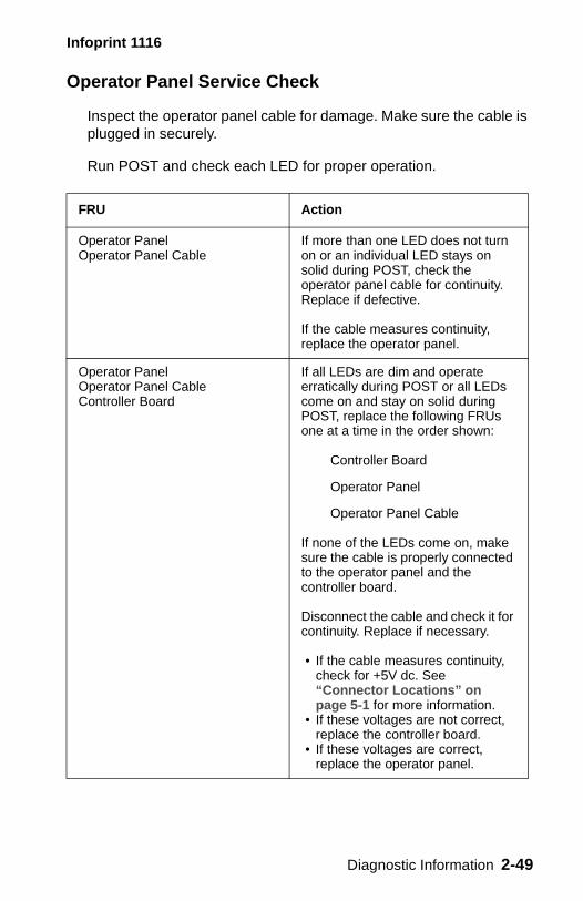
Operator Panel Service Check
Inspect the operator panel cable for damage. Make sure the cable is plugged in securely.
Run POST and check each LED for proper operation.
FRU Action
Operator Panel Operator Panel Cable
If more than one LED does not turn on or an individual LED stays on solid during POST, check the operator panel cable for continuity. Replace if defective.
If the cable measures continuity, replace the operator panel.
Operator Panel Operator Panel CableController Board
If all LEDs are dim and operate erratically during POST or all LEDs come on and stay on solid during POST, replace the following FRUs one at a time in the order shown:
Controller Board
Operator Panel
Operator Panel Cable
If none of the LEDs come on, make sure the cable is properly connected to the operator panel and the controller board.
Disconnect the cable and check it for continuity. Replace if necessary.
• If the cable measures continuity, check for +5V dc. See “Connector Locations” on page 5-1 for more information.
• If these voltages are not correct, replace the controller board.
• If these voltages are correct, replace the operator panel.
Diagnostic Information 2-49
Infoprint 1116
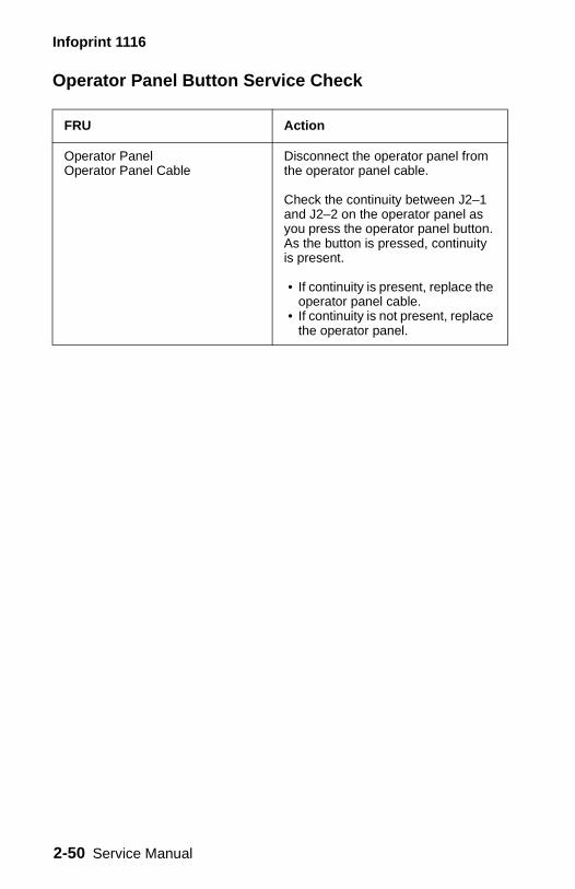
Operator Panel Button Service Check
FRU Action
Operator PanelOperator Panel Cable
Disconnect the operator panel from the operator panel cable.
Check the continuity between J2–1 and J2–2 on the operator panel as you press the operator panel button. As the button is pressed, continuity is present.
• If continuity is present, replace the operator panel cable.
• If continuity is not present, replace the operator panel.
2-50 Service Manual
Infoprint 1116
Paper Feed Service Checks
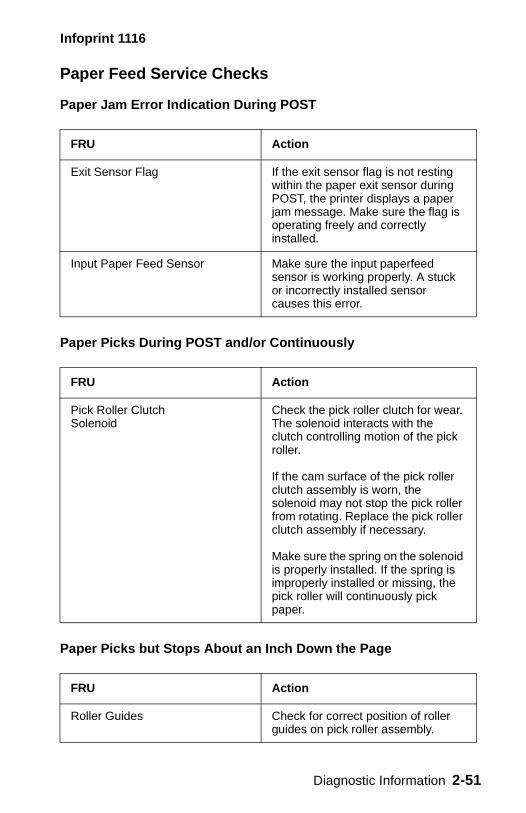
Paper Jam Error Indication During POST
Paper Picks During POST and/or Continuously
Paper Picks but Stops About an Inch Down the Page
FRU Action
Exit Sensor Flag If the exit sensor flag is not resting within the paper exit sensor during POST, the printer displays a paper jam message. Make sure the flag is operating freely and correctly installed.
Input Paper Feed Sensor Make sure the input paperfeed sensor is working properly. A stuck or incorrectly installed sensor causes this error.
FRU Action
Pick Roller Clutch Solenoid
Check the pick roller clutch for wear. The solenoid interacts with the clutch controlling motion of the pick roller.
If the cam surface of the pick roller clutch assembly is worn, the solenoid may not stop the pick roller from rotating. Replace the pick roller clutch assembly if necessary.
Make sure the spring on the solenoid is properly installed. If the spring is improperly installed or missing, the pick roller will continuously pick paper.
FRU Action
Roller Guides Check for correct position of roller guides on pick roller assembly.
Diagnostic Information 2-51
Infoprint 1116
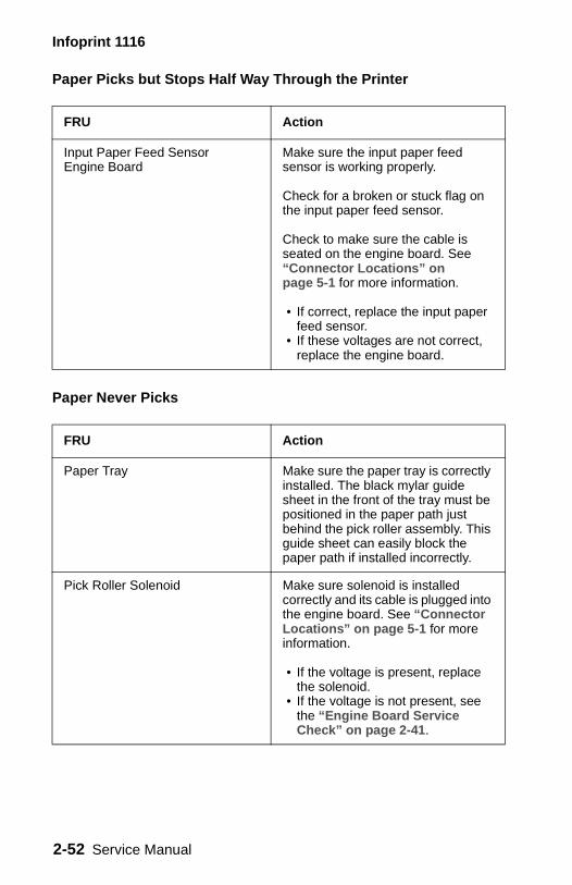
Paper Picks but Stops Half Way Through the Printer
Paper Never Picks
FRU Action
Input Paper Feed Sensor Engine Board
Make sure the input paper feed sensor is working properly.
Check for a broken or stuck flag on the input paper feed sensor.
Check to make sure the cable is seated on the engine board. See “Connector Locations” on page 5-1 for more information.
• If correct, replace the input paper feed sensor.
• If these voltages are not correct, replace the engine board.
FRU Action
Paper Tray Make sure the paper tray is correctly installed. The black mylar guide sheet in the front of the tray must be positioned in the paper path just behind the pick roller assembly. This guide sheet can easily block the paper path if installed incorrectly.
Pick Roller Solenoid Make sure solenoid is installed correctly and its cable is plugged into the engine board. See “Connector Locations” on page 5-1 for more information.
• If the voltage is present, replace the solenoid.
• If the voltage is not present, see the “Engine Board Service Check” on page 2-41.
2-52 Service Manual
Infoprint 1116
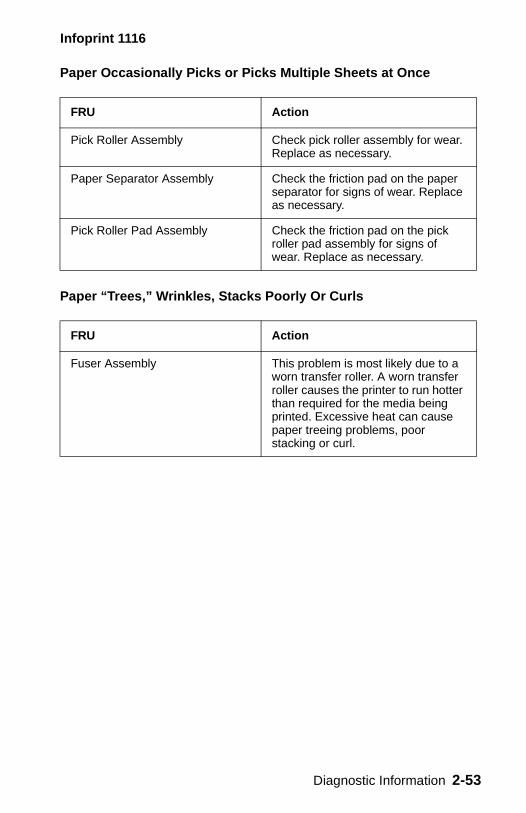
Paper Occasionally Picks or Picks Multiple Sheets at Once
Paper “Trees,” Wrinkles, Stacks Poorly Or Curls
FRU Action
Pick Roller Assembly Check pick roller assembly for wear. Replace as necessary.
Paper Separator Assembly Check the friction pad on the paper separator for signs of wear. Replace as necessary.
Pick Roller Pad Assembly Check the friction pad on the pick roller pad assembly for signs of wear. Replace as necessary.
FRU Action
Fuser Assembly This problem is most likely due to a worn transfer roller. A worn transfer roller causes the printer to run hotter than required for the media being printed. Excessive heat can cause paper treeing problems, poor stacking or curl.
Diagnostic Information 2-53
Infoprint 1116
Parallel Port Service Check
1. Perform a print test to make sure the printer prints correctly. See “Ready” on page 2-3 for more information.
2. Be sure the printer cable is designed for bidirectional printing.3. Be sure the user application is set up correctly. 4. Try enabling the parallel port pull–up resistors. See “Parallel
Mode 1” on page 3-27. Try printing a test page after enabling resistors. If the printer still does not print, disable the resistors.
5. If the internal print test page prints correctly, the user application/printer driver is set up correctly and the correct bidirectional parallel cable is installed, yet the printer still fails to print on command from the host computer, replace the controller board.
2-54 Service Manual
Infoprint 1116
Print Quality Service Checks
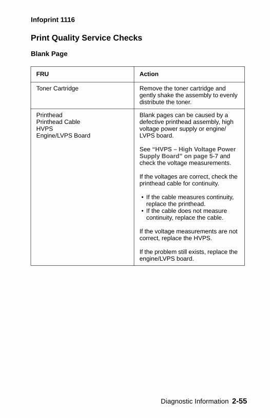
Blank Page
FRU Action
Toner Cartridge Remove the toner cartridge and gently shake the assembly to evenly distribute the toner.
Printhead Printhead Cable HVPS Engine/LVPS Board
Blank pages can be caused by a defective printhead assembly, high voltage power supply or engine/ LVPS board.
See “HVPS – High Voltage Power Supply Board” on page 5-7 and check the voltage measurements.
If the voltages are correct, check the printhead cable for continuity.
• If the cable measures continuity, replace the printhead.
• If the cable does not measure continuity, replace the cable.
If the voltage measurements are not correct, replace the HVPS.
If the problem still exists, replace the engine/LVPS board.
Diagnostic Information 2-55
Infoprint 1116
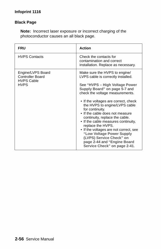
Black Page
Note: Incorrect laser exposure or incorrect charging of the photoconductor causes an all black page.
FRU Action
HVPS Contacts Check the contacts for contamination and correct installation. Replace as necessary.
Engine/LVPS BoardController BoardHVPS Cable HVPS
Make sure the HVPS to engine/ LVPS cable is correctly installed.
See “HVPS – High Voltage Power Supply Board” on page 5-7 and check the voltage measurements.
• If the voltages are correct, check the HVPS to engine/LVPS cable for continuity.
• If the cable does not measure continuity, replace the cable.
• If the cable measures continuity, replace the HVPS.
• If the voltages are not correct, see “Low Voltage Power Supply (LVPS) Service Check” on page 2-44 and “Engine Board Service Check” on page 2-41.
2-56 Service Manual
Infoprint 1116
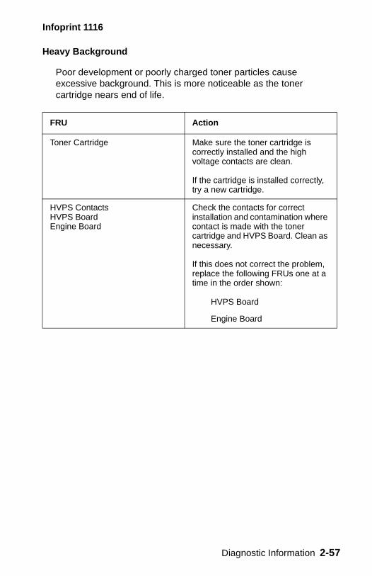
Heavy Background
Poor development or poorly charged toner particles cause excessive background. This is more noticeable as the toner cartridge nears end of life.
FRU Action
Toner Cartridge Make sure the toner cartridge is correctly installed and the high voltage contacts are clean.
If the cartridge is installed correctly, try a new cartridge.
HVPS Contacts HVPS Board Engine Board
Check the contacts for correct installation and contamination where contact is made with the toner cartridge and HVPS Board. Clean as necessary.
If this does not correct the problem, replace the following FRUs one at a time in the order shown:
HVPS Board
Engine Board
Diagnostic Information 2-57
Infoprint 1116
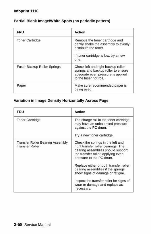
Partial Blank Image/White Spots (no periodic pattern)
Variation in Image Density Horizontally Across Page
FRU Action
Toner Cartridge Remove the toner cartridge and gently shake the assembly to evenly distribute the toner.
If toner cartridge is low, try a new one.
Fuser Backup Roller Springs Check left and right backup roller springs and backup roller to ensure adequate even pressure is applied to the fuser hot roll.
Paper Make sure recommended paper is being used.
FRU Action
Toner Cartridge The charge roll in the toner cartridge may have an unbalanced pressure against the PC drum.
Try a new toner cartridge.
Transfer Roller Bearing Assembly Transfer Roller
Check the springs in the left and right transfer roller bearings. The bearing assemblies should support the transfer roller, applying even pressure to the PC drum.
Replace either or both transfer roller bearing assemblies if the springs show signs of damage or fatigue.
Inspect the transfer roller for signs of wear or damage and replace as necessary.
2-58 Service Manual
Infoprint 1116
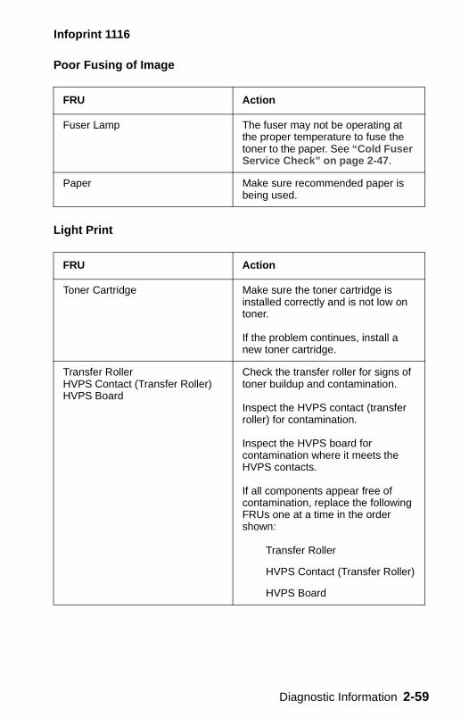
Poor Fusing of Image
Light Print
FRU Action
Fuser Lamp The fuser may not be operating at the proper temperature to fuse the toner to the paper. See “Cold Fuser Service Check” on page 2-47.
Paper Make sure recommended paper is being used.
FRU Action
Toner Cartridge Make sure the toner cartridge is installed correctly and is not low on toner.
If the problem continues, install a new toner cartridge.
Transfer Roller HVPS Contact (Transfer Roller) HVPS Board
Check the transfer roller for signs of toner buildup and contamination.
Inspect the HVPS contact (transfer roller) for contamination.
Inspect the HVPS board for contamination where it meets the HVPS contacts.
If all components appear free of contamination, replace the following FRUs one at a time in the order shown:
Transfer Roller
HVPS Contact (Transfer Roller)
HVPS Board
Diagnostic Information 2-59
Infoprint 1116
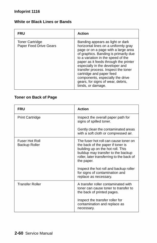
White or Black Lines or Bands
Toner on Back of Page
FRU Action
Toner Cartridge Paper Feed Drive Gears
Banding appears as light or dark horizontal lines on a uniformly gray page or on a page with a large area of graphics. Banding is primarily due to a variation in the speed of the paper as it feeds through the printer especially in the developer and transfer process. Inspect the toner cartridge and paper feed components, especially the drive gears, for signs of wear, debris, binds, or damage.
FRU Action
Print Cartridge Inspect the overall paper path for signs of spilled toner.
Gently clean the contaminated areas with a soft cloth or compressed air.
Fuser Hot Roll Backup Roller
The fuser hot roll can cause toner on the back of the paper if toner is building up on the hot roll. This buildup may transfer to the backup roller, later transferring to the back of the paper.
Inspect the hot roll and backup roller for signs of contamination and replace as necessary.
Transfer Roller A transfer roller contaminated with toner can cause toner to transfer to the back of printed pages.
Inspect the transfer roller for contamination and replace as necessary.
2-60 Service Manual

Infoprint 1116
Incorrect Characters Print
Make sure the correct printer driver software is installed. Incorrect software can cause incorrect characters to print and the image may not fit the page.
Diagnostic Information 2-61
Infoprint 1116
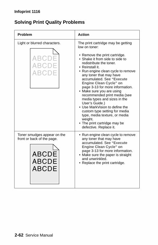
Solving Print Quality Problems
Problem Action
Light or blurred characters. The print cartridge may be getting low on toner:
• Remove the print cartridge. • Shake it from side to side to
redistribute the toner. • Reinstall it.• Run engine clean cycle to remove
any toner that may have accumulated. See “Execute Engine Clean Cycle” on page 3-13 for more information.
• Make sure you are using recommended print media (see media types and sizes in the User’s Guide.)
• Use MarkVision to define the custom type setting for media type, media texture, or media weight.
• The print cartridge may be defective. Replace it.
Toner smudges appear on the front or back of the page.
• Run engine clean cycle to remove any toner that may have accumulated. See “Execute Engine Clean Cycle” on page 3-13 for more information.
• Make sure the paper is straight and unwrinkled.
• Replace the print cartridge.
2-62 Service Manual
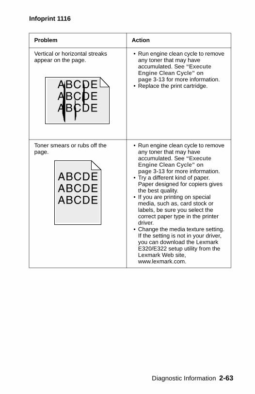
Infoprint 1116
Vertical or horizontal streaks appear on the page.
• Run engine clean cycle to remove any toner that may have accumulated. See “Execute Engine Clean Cycle” on page 3-13 for more information.
• Replace the print cartridge.
Toner smears or rubs off the page.
• Run engine clean cycle to remove any toner that may have accumulated. See “Execute Engine Clean Cycle” on page 3-13 for more information.
• Try a different kind of paper. Paper designed for copiers gives the best quality.
• If you are printing on special media, such as, card stock or labels, be sure you select the correct paper type in the printer driver.
• Change the media texture setting. If the setting is not in your driver, you can download the Lexmark E320/E322 setup utility from the Lexmark Web site, www.lexmark.com.
Problem Action
Diagnostic Information 2-63
Infoprint 1116
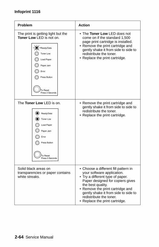
The print is getting light but the Toner Low LED is not on.
• The Toner Low LED does not come on if the standard 1,500 page print cartridge is installed.
• Remove the print cartridge and gently shake it from side to side to redistribute the toner.
• Replace the print cartridge.
The Toner Low LED is on. • Remove the print cartridge and gently shake it from side to side to redistribute the toner.
• Replace the print cartridge.
Solid black areas on transparencies or paper contains white streaks.
• Choose a different fill pattern in your software application.
• Try a different type of paper. Paper designed for copiers gives the best quality.
• Remove the print cartridge and gently shake it from side to side to redistribute the toner.
• Replace the print cartridge.
Problem Action
2-64 Service Manual
Infoprint 1116
Faint images or repetitive spots appear on the page.
• Select a different media type or form type setting from your printer driver.
• Try a different type of paper. Paper designed for copiers gives the best quality.
• Replace the print cartridge.
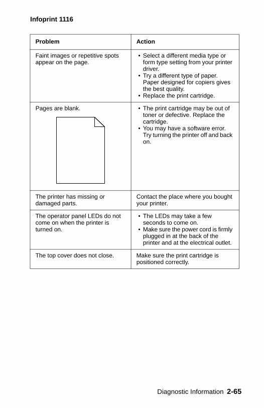
Pages are blank. • The print cartridge may be out of toner or defective. Replace the cartridge.
• You may have a software error. Try turning the printer off and back on.
The printer has missing or damaged parts.
Contact the place where you bought your printer.
The operator panel LEDs do not come on when the printer is turned on.
• The LEDs may take a few seconds to come on.
• Make sure the power cord is firmly plugged in at the back of the printer and at the electrical outlet.
The top cover does not close. Make sure the print cartridge is positioned correctly.
Problem Action
Diagnostic Information 2-65
Infoprint 1116
The printer is on, but nothing prints.
• Make sure the print cartridge is installed properly.
• Make sure the parallel or USB cable is firmly plugged into the connector on the back of the printer.
• Press the operator panel button with a brief button press to print a test page to determine whether the problem is with the printer or the computer.
– If you can print a test page, the problem is in the computer or the software application.
– If you cannot print a test page, call for service.
Toner Low LED is on and printing stops.
If you are using a 3K or 6K print cartridge and the Toner Low alarm is set to on, the printer stops printing until you replace the print cartridge.
– Download the Lexmark E320/E322 Setup Utility from the Lexmark Web site, www.lexmark.com to change the Toner Low alarm.
The media skews or buckles. • Don’t overfill Tray 1 or the optional Tray 2 (see media capacities in the media types and sizes table in the User’s Guide).
• Make sure the paper guides are flush against the edges of the media.
The paper sticks together/printer feeds multiple sheets of paper.
• Remove the paper from Tray 1 or the optional Tray 2 and fan the paper.
• Don’t overfill Tray 1 or the optional Tray 2 (see media capacities in the media types and sizes chart in the User’s Guide).
Problem Action
2-66 Service Manual
Infoprint 1116
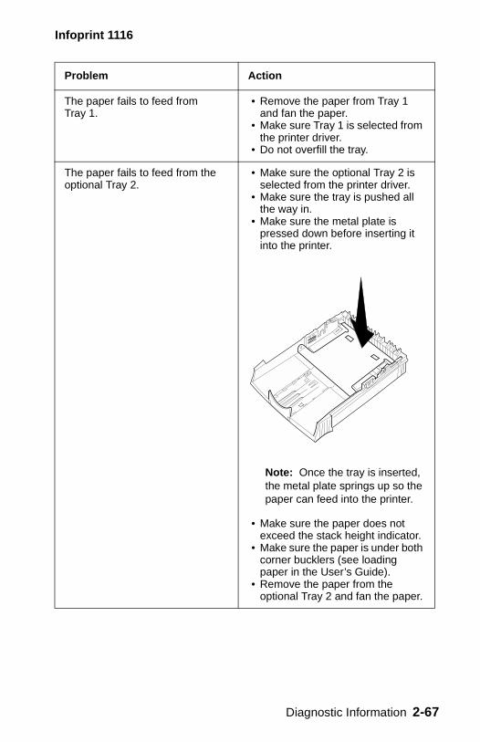
The paper fails to feed from Tray 1.
• Remove the paper from Tray 1 and fan the paper.
• Make sure Tray 1 is selected from the printer driver.
• Do not overfill the tray.
The paper fails to feed from the optional Tray 2.
• Make sure the optional Tray 2 is selected from the printer driver.
• Make sure the tray is pushed all the way in.
• Make sure the metal plate is pressed down before inserting it into the printer.
Note: Once the tray is inserted, the metal plate springs up so the paper can feed into the printer.
• Make sure the paper does not exceed the stack height indicator.
• Make sure the paper is under both corner bucklers (see loading paper in the User’s Guide).
• Remove the paper from the optional Tray 2 and fan the paper.
Problem Action
Diagnostic Information 2-67
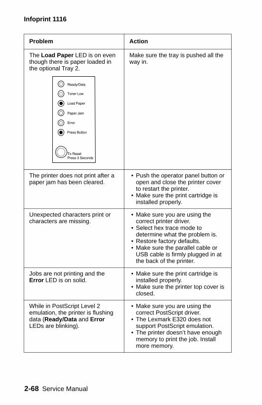
Infoprint 1116
The Load Paper LED is on even though there is paper loaded in the optional Tray 2.
Make sure the tray is pushed all the way in.
The printer does not print after a paper jam has been cleared.
• Push the operator panel button or open and close the printer cover to restart the printer.
• Make sure the print cartridge is installed properly.
Unexpected characters print or characters are missing.
• Make sure you are using the correct printer driver.
• Select hex trace mode to determine what the problem is.
• Restore factory defaults. • Make sure the parallel cable or
USB cable is firmly plugged in at the back of the printer.
Jobs are not printing and the Error LED is on solid.
• Make sure the print cartridge is installed properly.
• Make sure the printer top cover is closed.
While in PostScript Level 2 emulation, the printer is flushing data (Ready/Data and Error LEDs are blinking).
• Make sure you are using the correct PostScript driver.
• The Lexmark E320 does not support PostScript emulation.
• The printer doesn’t have enough memory to print the job. Install more memory.
Problem Action
2-68 Service Manual
Infoprint 1116
You want to use manual duplex but cannot find it on your printer.
Your printer driver may not support manual duplex. Go to the Lexmark Web site, www.lexmark.com to download the latest printer driver.
While using manual duplex, the printer gets a paper jam.
A paper jam interrupts the duplex process. As a result, the information on the page that jammed is lost.
• Cancel your print job and press the operator panel with a long button press (approximately 3 seconds) to reset the printer.
• Resend your print job.
Problem Action
Diagnostic Information 2-69
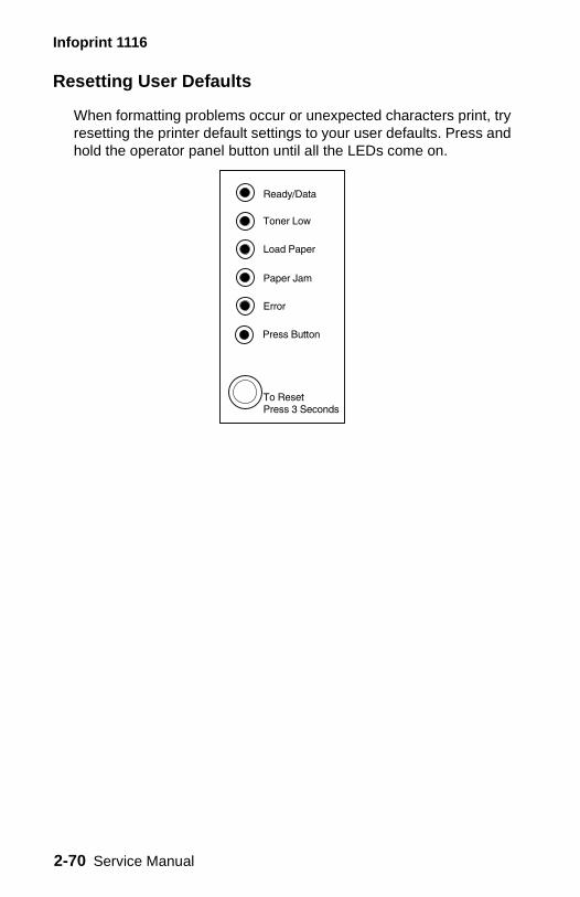
Infoprint 1116
Resetting User Defaults
When formatting problems occur or unexpected characters print, try resetting the printer default settings to your user defaults. Press and hold the operator panel button until all the LEDs come on.
2-70 Service Manual
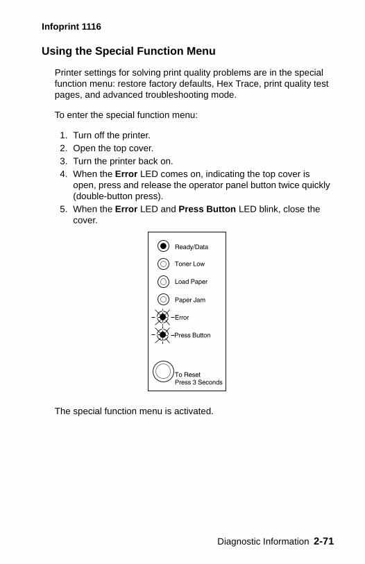
Infoprint 1116
Using the Special Function Menu
Printer settings for solving print quality problems are in the special function menu: restore factory defaults, Hex Trace, print quality test pages, and advanced troubleshooting mode.
To enter the special function menu:
1. Turn off the printer.2. Open the top cover.3. Turn the printer back on.4. When the Error LED comes on, indicating the top cover is
open, press and release the operator panel button twice quickly (double-button press).
5. When the Error LED and Press Button LED blink, close the cover.
The special function menu is activated.
Diagnostic Information 2-71
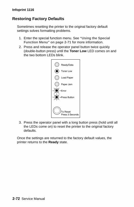
Infoprint 1116
Restoring Factory Defaults
Sometimes resetting the printer to the original factory default settings solves formatting problems.
1. Enter the special function menu. See “Using the Special Function Menu” on page 2-71 for more information.
2. Press and release the operator panel button twice quickly (double-button press) until the Toner Low LED comes on and the two bottom LEDs blink.
3. Press the operator panel with a long button press (hold until all the LEDs come on) to reset the printer to the original factory defaults.
Once the settings are returned to the factory default values, the printer returns to the Ready state.
2-72 Service Manual
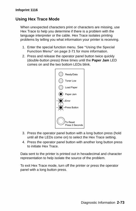
Infoprint 1116
Using Hex Trace Mode
When unexpected characters print or characters are missing, use Hex Trace to help you determine if there is a problem with the language interpreter or the cable. Hex Trace isolates printing problems by telling you what information your printer is receiving.
1. Enter the special function menu. See “Using the Special Function Menu” on page 2-71 for more information.
2. Press and release the operator panel button twice quickly (double-button press) three times until the Paper Jam LED comes on and the two bottom LEDs blink.
3. Press the operator panel button with a long button press (hold until all the LEDs come on) to select the Hex Trace setting.
4. Press the operator panel button with another long button press to initiate Hex Trace.
Data sent to the printer is printed out in hexadecimal and character representation to help isolate the source of the problem.
To exit Hex Trace mode, turn off the printer or press the operator panel with a long button press.
Diagnostic Information 2-73
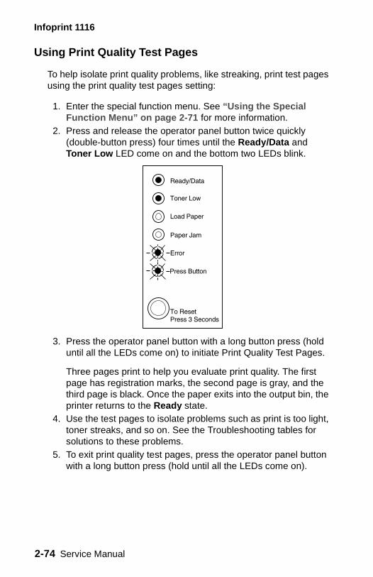
Infoprint 1116
Using Print Quality Test Pages
To help isolate print quality problems, like streaking, print test pages using the print quality test pages setting:
1. Enter the special function menu. See “Using the Special Function Menu” on page 2-71 for more information.
2. Press and release the operator panel button twice quickly (double-button press) four times until the Ready/Data and Toner Low LED come on and the bottom two LEDs blink.
3. Press the operator panel button with a long button press (hold until all the LEDs come on) to initiate Print Quality Test Pages.
Three pages print to help you evaluate print quality. The first page has registration marks, the second page is gray, and the third page is black. Once the paper exits into the output bin, the printer returns to the Ready state.
4. Use the test pages to isolate problems such as print is too light, toner streaks, and so on. See the Troubleshooting tables for solutions to these problems.
5. To exit print quality test pages, press the operator panel button with a long button press (hold until all the LEDs come on).
2-74 Service Manual

Infoprint 1116
Advanced Troubleshooting Mode
Refer to “Advanced Troubleshooting” in the User’s Guide for information about advanced troubleshooting mode settings.
Diagnostic Information 2-75

Infoprint 1116
2-76 Service Manual
Infoprint 1116
3. Diagnostic Aids
Start
This chapter describes procedures you can use to identify printer failures and verify that repairs have corrected the problem.
Performing Self Test
At power–up, each LED turns on and off in reverse sequence, starting with Press Button and ending with Ready. Each LED remains on for approximately one second, but no more than approximately two seconds. This cycling repeats as needed during the execution of the self test. The printer performs the cycle at least once. Additional cycles can be interrupted at any point in the cycle indicating the self test is complete.
Information Priority
The priority for displaying information on the operator panel is:
• Service information• Top cover open • All other information in the order of occurrence
Diagnostic Aids 3-1
Infoprint 1116
Printer Operation Modes
The printer supports six distinct modes of operation. Each of the following operations may only be performed if the printer is in the correct operation mode.
The six modes are:
• Normal printing • Demo printing • Diagnostics test • Special function menu • Configuration mode • Hex trace
The mode entry table lists steps to enter and exit each mode. See “Printer Modes Summary Table” on page 3-3 for details.
3-2 Service Manual
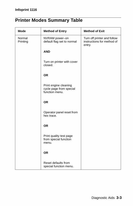
Infoprint 1116
Printer Modes Summary Table
Mode Method of Entry Method of Exit
Normal Printing
NVRAM power–on default flag set to normal
AND
Turn on printer with cover closed.
OR
Print engine cleaning cycle page from special function menu.
OR
Operator panel reset from hex trace.
OR
Print quality test page from special function menu.
OR
Reset defaults from special function menu.
Turn off printer and follow instructions for method of entry.
Diagnostic Aids 3-3
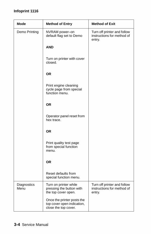
Infoprint 1116
Demo Printing NVRAM power–on default flag set to Demo
AND
Turn on printer with cover closed.
OR
Print engine cleaning cycle page from special function menu.
OR
Operator panel reset from hex trace.
OR
Print quality test page from special function menu.
OR
Reset defaults from special function menu.
Turn off printer and follow instructions for method of entry.
Diagnostics Menu
Turn on printer while pressing the button with the top cover open.
Once the printer posts the top cover open indication, close the top cover.
Turn off printer and follow instructions for method of entry.
Mode Method of Entry Method of Exit
3-4 Service Manual
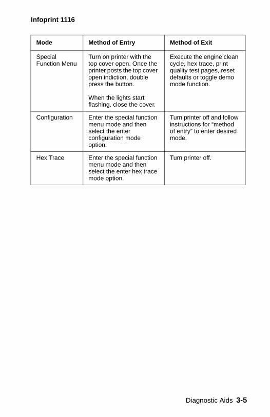
Infoprint 1116
Special Function Menu
Turn on printer with the top cover open. Once the printer posts the top cover open indiction, double press the button.
When the lights start flashing, close the cover.
Execute the engine clean cycle, hex trace, print quality test pages, reset defaults or toggle demo mode function.
Configuration Enter the special function menu mode and then select the enter configuration mode option.
Turn printer off and follow instructions for “method of entry” to enter desired mode.
Hex Trace Enter the special function menu mode and then select the enter hex trace mode option.
Turn printer off.
Mode Method of Entry Method of Exit
Diagnostic Aids 3-5
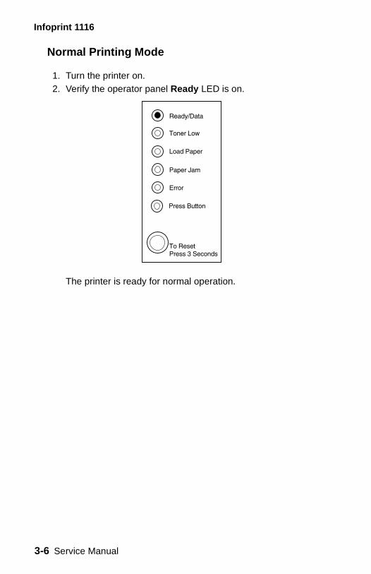
Infoprint 1116
Normal Printing Mode
1. Turn the printer on. 2. Verify the operator panel Ready LED is on.
The printer is ready for normal operation.
3-6 Service Manual
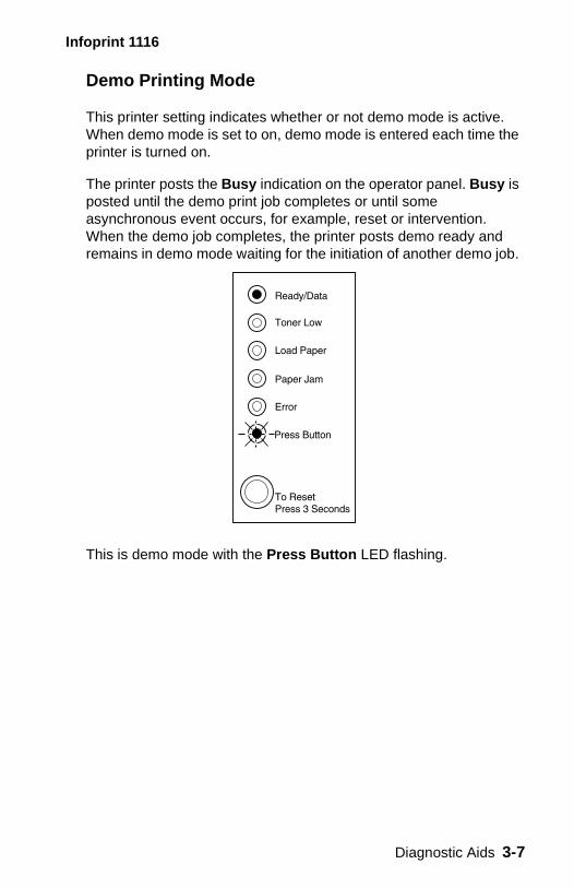
Infoprint 1116
Demo Printing Mode
This printer setting indicates whether or not demo mode is active. When demo mode is set to on, demo mode is entered each time the printer is turned on.
The printer posts the Busy indication on the operator panel. Busy is posted until the demo print job completes or until some asynchronous event occurs, for example, reset or intervention. When the demo job completes, the printer posts demo ready and remains in demo mode waiting for the initiation of another demo job.
This is demo mode with the Press Button LED flashing.
Diagnostic Aids 3-7
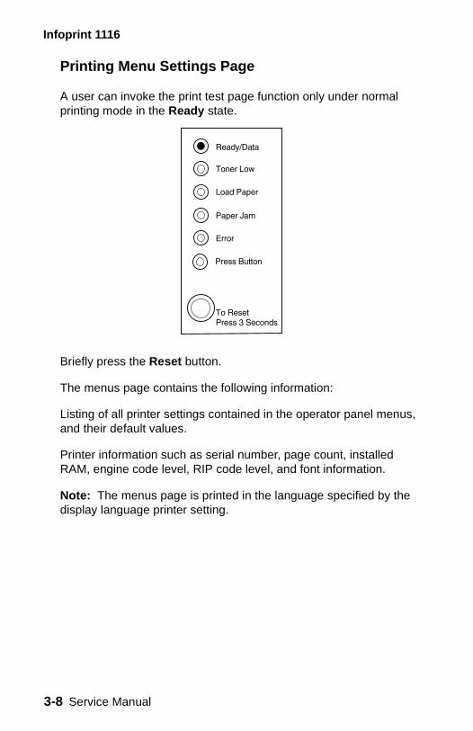
Infoprint 1116
Printing Menu Settings Page
A user can invoke the print test page function only under normal printing mode in the Ready state.
Briefly press the Reset button.
The menus page contains the following information:
Listing of all printer settings contained in the operator panel menus, and their default values.
Printer information such as serial number, page count, installed RAM, engine code level, RIP code level, and font information.
Note: The menus page is printed in the language specified by the display language printer setting.
3-8 Service Manual
Infoprint 1116
Diagnostic Tests Mode
The diagnostic tests mode causes the printers internal tests to be performed. If any of the diagnostic tests fail, a service indication is posted. You can determine which test failed by accessing the service code associated with the service error. The secondary service code is displayed by performing a button press while the service indication is posted on the operator panel.
If the printer completes all its diagnostic tests successfully, Toner Low LED blinks. To exit diagnostics, turn off the printer.
While running diagnostics, the printer performs the following memory tests:
• Standard memory test • Optional memory test
When the printer enters Normal or Demo modes, the total amount of installed memory detected during the POST sequence is compared with an NVRAM value representing the printer total installed memory.
• If the amount of detected memory matches the value stored in NVRAM, the printer doesn’t perform a Memory Test during POST sequence into Normal or Demo modes.
• If the amount of detected memory does not match the NVRAM value representing total installed memory, the printer assumes the user has changed the printers memory configuration by adding or removing optional memory.
To verify the new memory configuration, the printer performs a full Memory Test and then updates the NVRAM value representing the total installed memory.
Note: The printer always performs a complete Memory Test when executing the Diagnostics Test.
Diagnostic Aids 3-9
Infoprint 1116
Entering Diagnostic Tests Mode
Perform the following steps to enter diagnostics test mode:
1. Turn the printer off.2. Open the printer cover.3. Press and hold the operator panel button.4. Turn the printer on.5. When the cover open error is indicated on the operator panel
(Error LED on), release the button.6. Close the cover.
The printer automatically runs the diagnostics test.
• If the tests pass, the Toner Low LED blinks. • If a test fails, a service indication is displayed.
Once the diagnostics test is complete, a one page Quick Test can be printed by briefly pressing the operator panel button.
3-10 Service Manual
Infoprint 1116
Special Function Menu
The special function menu lets the following functions be executed from the operator panel:
• Execute engine cleaning cycle• Reset defaults• Enter configuration mode• Enter hex trace• Print diagnostics/print quality test page• Set demo mode active/inactive
Entering Special Function Menu
1. Turn the printer off. 2. Open the printer cover. 3. Turn the printer on. 4. When the cover open error is indicated on the operator panel,
(Error LED on), double press the button. 5. When the Error and Press Button LEDs start flashing, close
the cover.
The special function menu is now active.
Diagnostic Aids 3-11
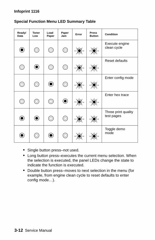
Infoprint 1116
Special Function Menu LED Summary Table
• Single button press–not used. • Long button press–executes the current menu selection. When
the selection is executed, the panel LEDs change the state to indicate the function is executed.
• Double button press–moves to next selection in the menu (for example, from engine clean cycle to reset defaults to enter config mode…).
Ready/Data
Toner Low
Load Paper
Paper Jam Error Press
Button Condition
Execute engine clean cycle
Reset defaults
Enter config mode
Enter hex trace
Three print quality test pages
Toggle demo mode
3-12 Service Manual
Infoprint 1116
Execute Engine Clean Cycle
The execute engine clean cycle function prints one blank page in a special cleaning mode. Prior to executing the engine cleaning cycle, place one sheet of paper into the automatic paper feed slot. The cleaning mode helps eliminate small specs of toner present in the background when printing.
See the Special Function Menu (page 3-11) and this action:
Perform a long button press until all LEDs are on solid. The printer feeds one sheet of paper.
Once the engine cleaning cycle pages are printed, the printer enters either normal printing or demo printing modes based on the NVRAM power–on default flag.
Reset Defaults
The operator panel reset operation is available when the printer is operating in its normal mode, demo mode, or hex trace mode, and when the operator panel indicates a printer state which permits the operator panel reset operation. For example, when the printer posts the paper jam indication, operator panel reset is not a permitted operation as long as the printer is in the paper jam state. On the other hand, when the printer posts the Busy indication, an operator panel reset is permitted.
Diagnostic Aids 3-13
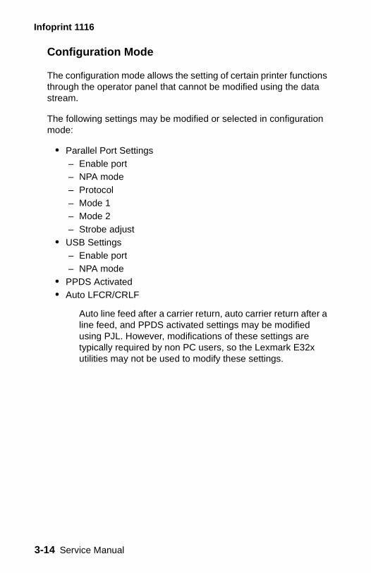
Infoprint 1116
Configuration Mode
The configuration mode allows the setting of certain printer functions through the operator panel that cannot be modified using the data stream.
The following settings may be modified or selected in configuration mode:
• Parallel Port Settings – Enable port – NPA mode – Protocol– Mode 1– Mode 2– Strobe adjust
• USB Settings – Enable port – NPA mode
• PPDS Activated • Auto LFCR/CRLF
Auto line feed after a carrier return, auto carrier return after a line feed, and PPDS activated settings may be modified using PJL. However, modifications of these settings are typically required by non PC users, so the Lexmark E32x utilities may not be used to modify these settings.
3-14 Service Manual
Infoprint 1116
Operator panel definitions while in configuration mode:
Entering Configuration Mode
Enter configuration mode by selecting the Enter Config Mode option on the special function menu.
The printer is in configuration mode when the Ready/Data LED comes on, and the Toner Low, Load Paper, Paper Jam, Error LEDs are off. Press Button indicates the Par Enabled setting.
To exit configuration mode, turn off the printer.
Once the printer enters configuration mode, replace the words on the panel overlay with one of the following overlays.
Action Definition
Double click button press
Moves through the configuration mode menu items.
Brief button press Moves through the displayed menu item value list.
Long button press Selects and saves the value displayed for the menu item.
To indicate to the user a setting has been saved, the printer displays the saving setting indication.
Diagnostic Aids 3-15
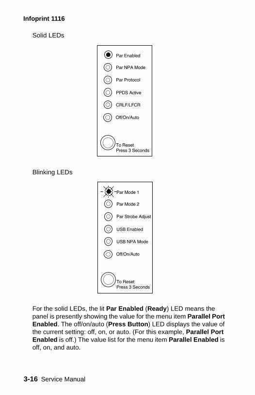
Infoprint 1116
Solid LEDs
Blinking LEDs
For the solid LEDs, the lit Par Enabled (Ready) LED means the panel is presently showing the value for the menu item Parallel Port Enabled. The off/on/auto (Press Button) LED displays the value of the current setting: off, on, or auto. (For this example, Parallel Port Enabled is off.) The value list for the menu item Parallel Enabled is off, on, and auto.
3-16 Service Manual
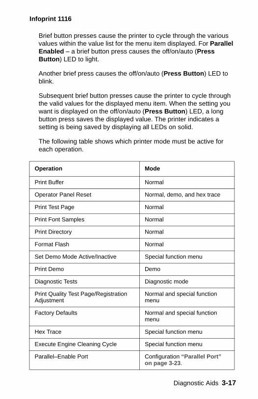
Infoprint 1116
Brief button presses cause the printer to cycle through the various values within the value list for the menu item displayed. For Parallel Enabled – a brief button press causes the off/on/auto (Press Button) LED to light.
Another brief press causes the off/on/auto (Press Button) LED to blink.
Subsequent brief button presses cause the printer to cycle through the valid values for the displayed menu item. When the setting you want is displayed on the off/on/auto (Press Button) LED, a long button press saves the displayed value. The printer indicates a setting is being saved by displaying all LEDs on solid.
The following table shows which printer mode must be active for each operation.
Operation Mode
Print Buffer Normal
Operator Panel Reset Normal, demo, and hex trace
Print Test Page Normal
Print Font Samples Normal
Print Directory Normal
Format Flash Normal
Set Demo Mode Active/Inactive Special function menu
Print Demo Demo
Diagnostic Tests Diagnostic mode
Print Quality Test Page/Registration Adjustment
Normal and special function menu
Factory Defaults Normal and special function menu
Hex Trace Special function menu
Execute Engine Cleaning Cycle Special function menu
Parallel–Enable Port Configuration “Parallel Port” on page 3-23.
Diagnostic Aids 3-17
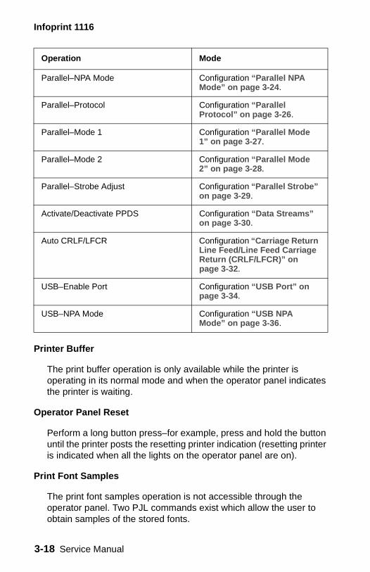
Infoprint 1116
Printer Buffer
The print buffer operation is only available while the printer is operating in its normal mode and when the operator panel indicates the printer is waiting.
Operator Panel Reset
Perform a long button press–for example, press and hold the button until the printer posts the resetting printer indication (resetting printer is indicated when all the lights on the operator panel are on).
Print Font Samples
The print font samples operation is not accessible through the operator panel. Two PJL commands exist which allow the user to obtain samples of the stored fonts.
Parallel–NPA Mode Configuration “Parallel NPA Mode” on page 3-24.
Parallel–Protocol Configuration “Parallel Protocol” on page 3-26.
Parallel–Mode 1 Configuration “Parallel Mode 1” on page 3-27.
Parallel–Mode 2 Configuration “Parallel Mode 2” on page 3-28.
Parallel–Strobe Adjust Configuration “Parallel Strobe” on page 3-29.
Activate/Deactivate PPDS Configuration “Data Streams” on page 3-30.
Auto CRLF/LFCR Configuration “Carriage Return Line Feed/Line Feed Carriage Return (CRLF/LFCR)” on page 3-32.
USB–Enable Port Configuration “USB Port” on page 3-34.
USB–NPA Mode Configuration “USB NPA Mode” on page 3-36.
Operation Mode
3-18 Service Manual

Infoprint 1116
Print Directory
Print directory is not supported by the operator panel. It is supported by issuing a PJL command.
Format Flash
Format flash is not supported by the operator panel. It is supported by issuing a PJL command.
Set Demo Mode Active/Inactive
The power–on default for the printer may be switched between normal and demo by activating/deactivating demo mode toggle.
Go to the Special Function Menu (see page 3-11) and perform the following:
1. Select Toggle Demo mode by double pressing the operator panel button until the Ready and Load Paper LEDs are on.
2. Perform a long button press until all LEDs are on solid.
Print Registration Adjustment
• Adjust the left margin until the registration box illustrated on the diagnostics test page is centered on the page.
• Adjust the top margin until the registration lines located at the bottom of the diamonds at the bottom of the page fall on the bottom edge of the page.
These settings may be modified by issuing PJL DEFAULT commands when the printer is in normal mode. The PJL variables used to describe registration are LLEFTMARGINOFFSET and LTOPMARGINOFFSET.
Diagnostic Aids 3-19
Infoprint 1116
Factory Defaults
When the printer is initialized, the printer environment returns to default settings.
There are of two types of default settings:
• Fixed default settings
Fixed default settings cannot be modified from their factory set values.
• Variable default settings
Variable default settings can be altered from their factory set values. Factory set values are never erased and may be restored at a later time.
Restoring Factory Defaults
Restoring factory defaults returns the printer settings to the original factory settings.
Go to the Special Function Menu (see page 3-11) and perform the following:
1. Select Reset Defaults mode by double pressing the operator panel button until the Toner Low LED is on.
2. Perform a long button press until all LEDs are on solid.
The printer is reset to factory defaults.
3-20 Service Manual
Infoprint 1116
Enter Hex Trace Mode
When the printer is in hex trace mode, it prints a hexadecimal and a character representation of a print job. The printer does not recognize any print controls or commands in this mode. A hex trace printout can be used to help isolate the cause of print problems. This is done by checking the control codes embedded within a print job.
Go to the Special Function Menu (see page 3-11) and perform the following:
1. Select Enter Hex Trace mode by double pressing the operator panel button until the Paper Jam LED is on.
2. Perform a long button press until all LEDs are on solid.
The printer is reset to factory defaults.
Hex trace mode can be exited by turning off the printer, or by pressing and holding the operator panel button to reset the printer.
Print Quality Test Pages
Go to the Special Function Menu (see page 3-11) and perform the following:
1. Select Three Print Quality Test Pages mode by double pressing the operator panel button until the Ready/Data and Toner Low LEDs are on.
2. Perform a long button press until all LEDs are on solid.
Diagnostic Aids 3-21
Infoprint 1116
When a test page is printed from the Special Function Menu:
• The first diagnostic test page illustrates print registration marks which aid the user during the print registration adjustment process.
In addition, the first diagnostic test page also includes the current value of some user default settings.Note: The diagnostics test page is printed in English only.
• The second page is gray. • The third page is black.
Notes:
– Both pages are used by service and manufacturing to evaluate print quality.
– Both diagnostic test pages can be printed from the print quality test pages function.
Once the print quality test pages are printed, the printer enters either normal printing or demo printing modes based on the NVRAM power–on default flag.
3-22 Service Manual
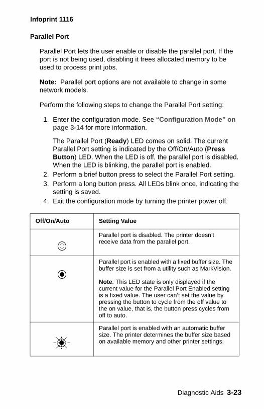
Infoprint 1116
Parallel Port
Parallel Port lets the user enable or disable the parallel port. If the port is not being used, disabling it frees allocated memory to be used to process print jobs.
Note: Parallel port options are not available to change in some network models.
Perform the following steps to change the Parallel Port setting:
1. Enter the configuration mode. See “Configuration Mode” on page 3-14 for more information.
The Parallel Port (Ready) LED comes on solid. The current Parallel Port setting is indicated by the Off/On/Auto (Press Button) LED. When the LED is off, the parallel port is disabled. When the LED is blinking, the parallel port is enabled.
2. Perform a brief button press to select the Parallel Port setting.3. Perform a long button press. All LEDs blink once, indicating the
setting is saved.4. Exit the configuration mode by turning the printer power off.
Off/On/Auto Setting Value
Parallel port is disabled. The printer doesn’t receive data from the parallel port.
Parallel port is enabled with a fixed buffer size. The buffer size is set from a utility such as MarkVision.
Note: This LED state is only displayed if the current value for the Parallel Port Enabled setting is a fixed value. The user can’t set the value by pressing the button to cycle from the off value to the on value, that is, the button press cycles from off to auto.
Parallel port is enabled with an automatic buffer size. The printer determines the buffer size based on available memory and other printer settings.
Diagnostic Aids 3-23
Infoprint 1116
Parallel NPA Mode
Parallel NPA mode allows two way communication between the host computer and the printer.
Perform the following steps to change the Parallel NPA setting:
1. Enter the configuration mode. See “Configuration Mode” on page 3-14 for more information.
2. Perform a double click button press. This moves to the Parallel NPA item on the configuration menu. The Parallel NPA (Data) LED comes on solid.
3. The current Parallel NPA setting is indicated by the Off/On/Auto (Press Button) LED.• When the LED is on solid, all data received by the printer
must be in NPA packets. Any non-packet data is rejected as bad packets.
• When the LED is off, the printer is not performing any NPA processing.
• When the LED is blinking, the printer examines incoming data and decides whether it is receiving NPA packets.
4. Perform a brief button press to select the Parallel NPA setting.5. Perform a long button press. All LEDs blink once, indicating the
setting is saved.6. Exit the configuration mode by turning the printer power off.
3-24 Service Manual
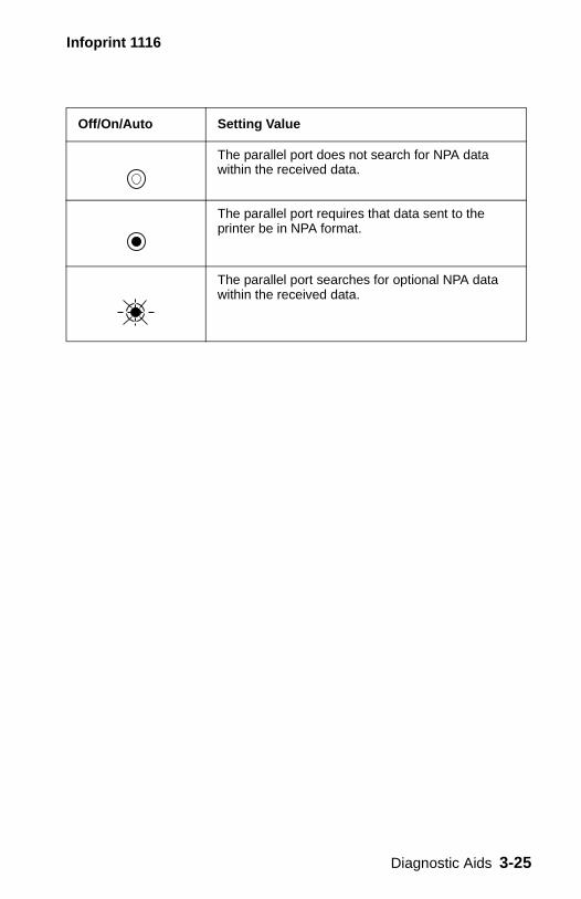
Infoprint 1116
Off/On/Auto Setting Value
The parallel port does not search for NPA data within the received data.
The parallel port requires that data sent to the printer be in NPA format.
The parallel port searches for optional NPA data within the received data.
Diagnostic Aids 3-25
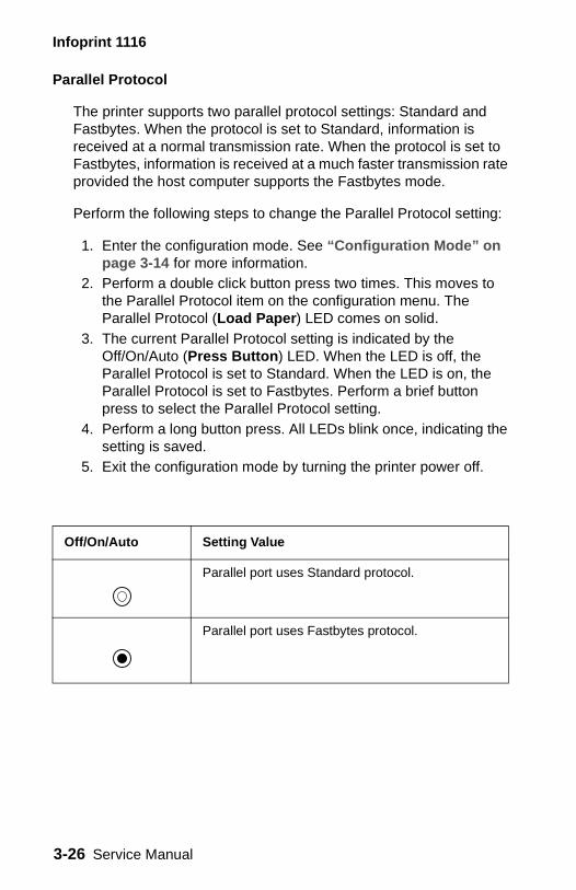
Infoprint 1116
Parallel Protocol
The printer supports two parallel protocol settings: Standard and Fastbytes. When the protocol is set to Standard, information is received at a normal transmission rate. When the protocol is set to Fastbytes, information is received at a much faster transmission rate provided the host computer supports the Fastbytes mode.
Perform the following steps to change the Parallel Protocol setting:
1. Enter the configuration mode. See “Configuration Mode” on page 3-14 for more information.
2. Perform a double click button press two times. This moves to the Parallel Protocol item on the configuration menu. The Parallel Protocol (Load Paper) LED comes on solid.
3. The current Parallel Protocol setting is indicated by the Off/On/Auto (Press Button) LED. When the LED is off, the Parallel Protocol is set to Standard. When the LED is on, the Parallel Protocol is set to Fastbytes. Perform a brief button press to select the Parallel Protocol setting.
4. Perform a long button press. All LEDs blink once, indicating the setting is saved.
5. Exit the configuration mode by turning the printer power off.
Off/On/Auto Setting Value
Parallel port uses Standard protocol.
Parallel port uses Fastbytes protocol.
3-26 Service Manual
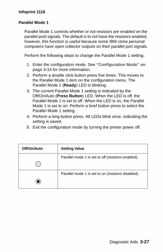
Infoprint 1116
Parallel Mode 1
Parallel Mode 1 controls whether or not resistors are enabled on the parallel post signals. The default is to not have the resistors enabled, however, this function is useful because some IBM clone personal computers have open collector outputs on their parallel port signals.
Perform the following steps to change the Parallel Mode 1 setting:
1. Enter the configuration mode. See “Configuration Mode” on page 3-14 for more information.
2. Perform a double click button press five times. This moves to the Parallel Mode 1 item on the configuration menu. The Parallel Mode 1 (Ready) LED is blinking.
3. The current Parallel Mode 1 setting is indicated by the Off/On/Auto (Press Button) LED. When the LED is off, the Parallel Mode 1 is set to off. When the LED is on, the Parallel Mode 1 is set to on. Perform a brief button press to select the Parallel Mode 1 setting.
4. Perform a long button press. All LEDs blink once, indicating the setting is saved.
5. Exit the configuration mode by turning the printer power off.
Off/On/Auto Setting Value
Parallel mode 1 is set to off (resistors enabled).
Parallel mode 1 is set to on (resistors disabled).
Diagnostic Aids 3-27
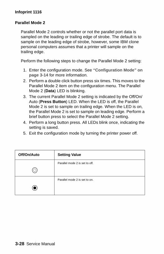
Infoprint 1116
Parallel Mode 2
Parallel Mode 2 controls whether or not the parallel port data is sampled on the leading or trailing edge of strobe. The default is to sample on the leading edge of strobe, however, some IBM clone personal computers assumes that a printer will sample on the trailing edge.
Perform the following steps to change the Parallel Mode 2 setting:
1. Enter the configuration mode. See “Configuration Mode” on page 3-14 for more information.
2. Perform a double click button press six times. This moves to the Parallel Mode 2 item on the configuration menu. The Parallel Mode 2 (Data) LED is blinking.
3. The current Parallel Mode 2 setting is indicated by the Off/On/Auto (Press Button) LED. When the LED is off, the Parallel Mode 2 is set to sample on trailing edge. When the LED is on, the Parallel Mode 2 is set to sample on leading edge. Perform a brief button press to select the Parallel Mode 2 setting.
4. Perform a long button press. All LEDs blink once, indicating the setting is saved.
5. Exit the configuration mode by turning the printer power off.
Off/On/Auto Setting Value
Parallel mode 2 is set to off.
Parallel mode 2 is set to on.
3-28 Service Manual
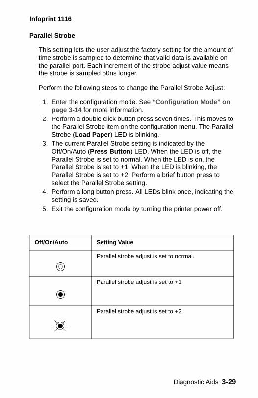
Infoprint 1116
Parallel Strobe
This setting lets the user adjust the factory setting for the amount of time strobe is sampled to determine that valid data is available on the parallel port. Each increment of the strobe adjust value means the strobe is sampled 50ns longer.
Perform the following steps to change the Parallel Strobe Adjust:
1. Enter the configuration mode. See “Configuration Mode” on page 3-14 for more information.
2. Perform a double click button press seven times. This moves to the Parallel Strobe item on the configuration menu. The Parallel Strobe (Load Paper) LED is blinking.
3. The current Parallel Strobe setting is indicated by the Off/On/Auto (Press Button) LED. When the LED is off, the Parallel Strobe is set to normal. When the LED is on, the Parallel Strobe is set to +1. When the LED is blinking, the Parallel Strobe is set to +2. Perform a brief button press to select the Parallel Strobe setting.
4. Perform a long button press. All LEDs blink once, indicating the setting is saved.
5. Exit the configuration mode by turning the printer power off.
Off/On/Auto Setting Value
Parallel strobe adjust is set to normal.
Parallel strobe adjust is set to +1.
Parallel strobe adjust is set to +2.
Diagnostic Aids 3-29
Infoprint 1116
Data Streams
Data Stream Specifications
To access the PPDS data stream, the PPDS setting must be set to active. When PPDS is active, the default Printer Language is changed to PPDS and the default PCL and PostScript SmartSwitch settings are changed to off.
Perform the following steps to change the PPDS setting:
1. Enter the configuration mode. See “Configuration Mode” on page 3-14 for more information.
2. Perform a double click button press three times. This moves to the PPDS item on the configuration menu. The PPDS (Paper Jam) LED comes on solid.
3. The current PPDS setting is indicated by the Off/On/Auto (Press Button) LED. When the LED is off, the PPDS is set to inactive. When the LED is on, the PPDS is set to active. Perform a brief button press to select the PPDS setting.
4. Perform a long button press. All LEDs blink once, indicating the setting is saved.
5. Exit the configuration mode by turning the printer power off.
Data Streams Infoprint 1116
PostScript Level 2 emulation
Standard
PPDS Standard
3-30 Service Manual
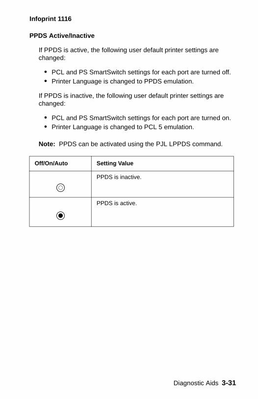
Infoprint 1116
PPDS Active/Inactive
If PPDS is active, the following user default printer settings are changed:
• PCL and PS SmartSwitch settings for each port are turned off. • Printer Language is changed to PPDS emulation.
If PPDS is inactive, the following user default printer settings are changed:
• PCL and PS SmartSwitch settings for each port are turned on. • Printer Language is changed to PCL 5 emulation.
Note: PPDS can be activated using the PJL LPPDS command.
Off/On/Auto Setting Value
PPDS is inactive.
PPDS is active.
Diagnostic Aids 3-31
Infoprint 1116
Carriage Return Line Feed/Line Feed Carriage Return (CRLF/LFCR)
This function controls whether or not the printer automatically performs a carriage return after a line feed control command and whether or not the printer automatically performs a line feed after a carriage return control command.
Perform the following steps to change the CRLF/LFCR setting:
1. Enter the configuration mode. See “Configuration Mode” on page 3-14 for more information.
2. Perform a double click button press four times. This moves to the CRLF/LFCR item on the configuration menu. The CRLF/LFCR (Error) LED comes on solid.
3. The current CRLF/LFCR setting is indicated by the Off/On/Auto (Press Button) LED.• When the LED is off, Auto CR after LF is off and Auto LF
after CR is off.• When the LED is on, Auto CR after LF is on and Auto LF
after CR is off.• When the LED is blinking, Auto CR after LF is off and Auto
LF after CR is on.4. Perform a brief button press to select the CRLF/LFCR setting.5. Perform a long button press. All LEDs blink once, indicating the
setting is saved.6. Exit the configuration mode by turning the printer power off.
3-32 Service Manual
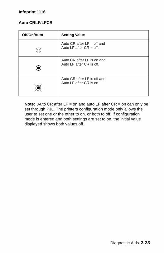
Infoprint 1116
Auto CRLF/LFCR
Note: Auto CR after LF = on and auto LF after CR = on can only be set through PJL. The printers configuration mode only allows the user to set one or the other to on, or both to off. If configuration mode is entered and both settings are set to on, the initial value displayed shows both values off.
Off/On/Auto Setting Value
Auto CR after LF = off and Auto LF after CR = off.
Auto CR after LF is on and Auto LF after CR is off.
Auto CR after LF is off and Auto LF after CR is on.
Diagnostic Aids 3-33
Infoprint 1116
USB Port
This menu item lets the user enable or disable the USB port. If the port is not being used, disabling it frees allocated memory to be used to process print jobs.
Perform the following steps to change the USB Port setting:
1. Enter the configuration mode. See “Configuration Mode” on page 3-14 for more information.
2. Perform a double click button press eight times. This moves to the USB Port item on the configuration menu. The USB Port (Paper Jam) LED is blinking.
3. The current USB Port setting is indicated by the Off/On/Auto (Press Button) LED. When the LED is off, the USB Port is disabled. When the LED is blinking, the USB Port is enabled. Perform a brief button press to select a different USB Port setting.
4. Perform a long button press. All LEDs blink once, indicating the setting is saved.
5. Exit the configuration mode by turning the printer power off.
3-34 Service Manual
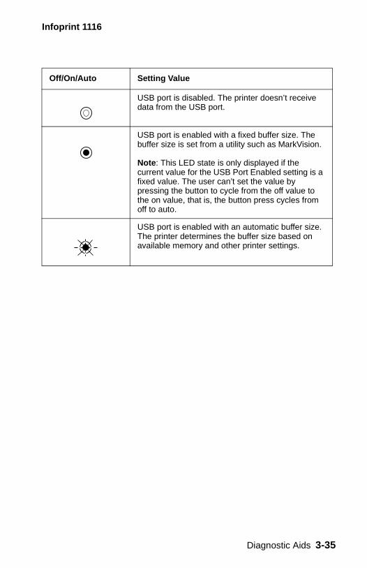
Infoprint 1116
Off/On/Auto Setting Value
USB port is disabled. The printer doesn’t receive data from the USB port.
USB port is enabled with a fixed buffer size. The buffer size is set from a utility such as MarkVision.
Note: This LED state is only displayed if the current value for the USB Port Enabled setting is a fixed value. The user can’t set the value by pressing the button to cycle from the off value to the on value, that is, the button press cycles from off to auto.
USB port is enabled with an automatic buffer size. The printer determines the buffer size based on available memory and other printer settings.
Diagnostic Aids 3-35
Infoprint 1116
USB NPA Mode
USB NPA mode allows for two way communication between the host computer and the printer.
Perform the following steps to change the USB NPA setting:
1. Enter the configuration mode. See “Configuration Mode” on page 3-14 for more information.
2. Perform a double click button press nine times. This moves to the USB NPA mode item on the configuration menu. The USB NPA (Error) LED is blinking.
3. The current USB NPA setting is indicated by the Off/On/Auto (Press Button) LED.• When the LED is off, the USB port does not search for NPA
data within the received data.• When the LED is blinking, the USB port searches for
optional NPA data within the received data.• When the LED is on solid, the USB port requires that data
sent to the printer be in NPA format.4. Perform a brief button press to select a different USB NPA
setting.5. Perform a long button press. All LEDs blink once, indicating the
setting is saved.6. Exit the configuration mode by turning the printer power off.
3-36 Service Manual
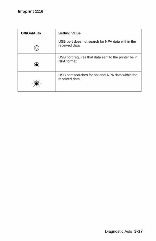
Infoprint 1116
Off/On/Auto Setting Value
USB port does not search for NPA data within the received data.
USB port requires that data sent to the printer be in NPA format.
USB port searches for optional NPA data within the received data.
Diagnostic Aids 3-37
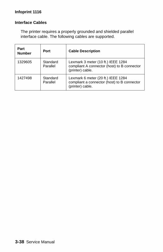
Infoprint 1116
Interface Cables
The printer requires a properly grounded and shielded parallel interface cable. The following cables are supported.
Part Number
Port Cable Description
1329605 Standard Parallel
Lexmark 3 meter (10 ft.) IEEE 1284 compliant A connector (host) to B connector (printer) cable.
1427498 Standard Parallel
Lexmark 6 meter (20 ft.) IEEE 1284 compliant a connector (host) to B connector (printer) cable.
3-38 Service Manual
Infoprint 1116
4. Repair Information
WARNING: Read the following before handling electronic parts.
Handling ESD-Sensitive Parts
Many electronic products use parts that are known to be sensitive to electrostatic discharge (ESD). To prevent damage to ESD-sensitive parts, follow the instructions below in addition to all the usual precautions, such as turning off power before removing logic boards:
• Keep the ESD-sensitive part in its original shipping container (a special “ESD bag”) until you are ready to install the part into the printer.
• Make the least-possible movements with your body to prevent an increase of static electricity from clothing fibers, carpets, and furniture.
• Put the ESD wrist strap on your wrist. Connect the wrist band to the system ground point. This discharges any static electricity in your body to the printer.
• Hold the ESD-sensitive part by its edge connector shroud (cover); do not touch its pins. If you are removing a pluggable module, use the correct tool.
• Do not place the ESD-sensitive part on the printer cover or on a metal table; if you need to put down the ESD-sensitive part for any reason, first put it into its special bag.
• Machine covers and metal tables are electrical grounds. They increase the risk of damage because they make a discharge path from your body through the ESD-sensitive part. (Large metal objects can be discharge paths without being grounded.)
• Prevent ESD-sensitive parts from being accidentally touched by other personnel. Install machine covers when you are not working on the machine, and do not put unprotected ESD-sensitive parts on a table.
• If possible, keep all ESD-sensitive parts in a grounded metal cabinet (case).
• Be extra careful in working with ESD-sensitive parts when cold-weather heating is used because low humidity increases static electricity.
Repair Information 4-1
Infoprint 1116
Removal Procedures
Be sure to unplug the power cord whenever you are working on the printer with one of the covers removed. Be sure to remove the print cartridge before you perform removal procedures.
Cover Removals
Access Cover
1. Open the front access cover.2. Press the center of the access cover down to release the side
pivot points.3. Remove the access cover.
Front Cover
1. Open the front cover. 2. Remove the two plastic clips from the front cover support arm
hinges. Note: Support and ease the charge roll assembly into a resting position when disengaging the front cover support arm hinges.
3. Disengage the front cover support arm hinges from the charge roll assembly.
4. Release the front cover from its pivot points.
Note: Lay the front cover to one side as the operator panel cable is attached to the controller board. See “Right Side Cover” on page 4-3 and “Controller Board Cage Removal” on page 4-4 for more information.
Top Cover
1. Open the front cover. 2. Remove the two top cover screws. 3. Remove the top cover.
4-2 Service Manual
Infoprint 1116
Right Side Cover
1. Open the front cover. See “Front Cover” on page 4-2 for more information.
2. Press the two right side cover finger tabs while releasing the center tab.
3. Remove the right side cover.
Left Side Cover
1. Open the front cover. See “Front Cover” on page 4-2 for more information.
2. Remove the top cover. See “Top Cover” on page 4-2 for more information.
3. Remove the left side cover screw.4. Release the left side cover tabs (2).5. Remove the left side cover.
Auto Sheet Feed (ASF) Assembly Removal
1. Open the front cover. See “Front Cover” on page 4-2 for more information.
2. Remove the top cover. See “Top Cover” on page 4-2 for more information.
3. Remove the left side cover. See “Left Side Cover” on page 4-3 for more information.
4. Remove the right side cover. See “Right Side Cover” on page 4-3 for more information.
5. Remove the two lower ASF screws. 6. Tilt or swing the lower rear auto sheet feed cover away from the
printer and remove. 7. Remove the two upper ASF screws. 8. Remove the ground strap screw. 9. Tilt or swing the top of the ASF away from the printer to
disengage the elongated hinge pivots. 10. Remove the auto sheet feed.
Repair Information 4-3

Infoprint 1116
Printhead Assembly Removal
1. Open the front cover. See “Front Cover” on page 4-2 for more information.
2. Remove the top cover. See “Top Cover” on page 4-2 for more information.
3. Remove the four top screws from the printhead mounting plate.
Note: There are two screws on each end of the printhead plate used to fasten the plate to the printer left and right side frame.
4. Remove the printhead plate ground strap screw. 5. Remove the controller cage screw from the printhead mounting
plate. 6. Disconnect the printhead cables. 7. Remove the three printhead screws. 8. Remove the printhead.
Controller Board Removal
1. Open the front cover. See “Front Cover” on page 4-2 for more information.
2. Remove the right side cover. See “Right Side Cover” on page 4-3 for more information.
3. Remove the controller board cover screw. 4. Disconnect cables from the controller board. 5. Remove the two parallel cable screws. 6. Remove the four controller board screws. 7. Remove the controller board.
Controller Board Cage Removal
1. Open the front cover. See “Front Cover” on page 4-2 for more information.
2. Remove the right side cover. See “Right Side Cover” on page 4-3 for more information.
3. Remove the controller board. See “Controller Board Removal” on page 4-4 for more information.
4. Remove the three screws holding the controller board cage to the printer side frame and remove cage from the frame.
4-4 Service Manual
Infoprint 1116
High Voltage Power Supply (HVPS) Removal
1. Open the front cover. See “Front Cover” on page 4-2 for more information.
2. Remove the top cover. See “Top Cover” on page 4-2 for more information.
3. Remove the left side cover. See “Left Side Cover” on page 4-3 for more information.
4. Remove the four HVPS board screws. 5. Disconnect connector from the HVPS board. 6. Remove the HVPS board.
Note: Use care with compression springs as they can fall out.
Cooling Fan Removal
1. Open the front cover. See “Front Cover” on page 4-2 for more information.
2. Remove the top cover. See “Top Cover” on page 4-2 for more information.
3. Remove the left side cover. See “Left Side Cover” on page 4-3 for more information.
4. Remove two cooling fan screws. 5. Remove the toner cartridge. 6. Tilt the printer carefully to the rear so it is resting on the ASF. 7. Remove the four bottom cover screws. 8. Disconnect the cooling fan cable from the engine card. 9. Remove the cooling fan.
Low Voltage Power Supply (LVPS) Removal
1. Remove the toner cartridge. 2. Tilt the printer carefully to the rear so it is resting on the ASF. 3. Remove the four bottom cover screws. 4. Disconnect the cables. 5. Remove four LVPS board screws.
Repair Information 4-5
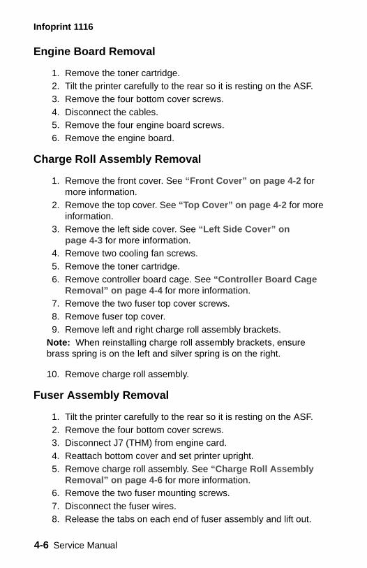
Infoprint 1116
Engine Board Removal
1. Remove the toner cartridge. 2. Tilt the printer carefully to the rear so it is resting on the ASF. 3. Remove the four bottom cover screws. 4. Disconnect the cables. 5. Remove the four engine board screws. 6. Remove the engine board.
Charge Roll Assembly Removal
1. Remove the front cover. See “Front Cover” on page 4-2 for more information.
2. Remove the top cover. See “Top Cover” on page 4-2 for more information.
3. Remove the left side cover. See “Left Side Cover” on page 4-3 for more information.
4. Remove two cooling fan screws. 5. Remove the toner cartridge. 6. Remove controller board cage. See “Controller Board Cage
Removal” on page 4-4 for more information. 7. Remove the two fuser top cover screws. 8. Remove fuser top cover. 9. Remove left and right charge roll assembly brackets.
Note: When reinstalling charge roll assembly brackets, ensure brass spring is on the left and silver spring is on the right.
10. Remove charge roll assembly.
Fuser Assembly Removal
1. Tilt the printer carefully to the rear so it is resting on the ASF. 2. Remove the four bottom cover screws. 3. Disconnect J7 (THM) from engine card.4. Reattach bottom cover and set printer upright.5. Remove charge roll assembly. See “Charge Roll Assembly
Removal” on page 4-6 for more information. 6. Remove the two fuser mounting screws. 7. Disconnect the fuser wires. 8. Release the tabs on each end of fuser assembly and lift out.
4-6 Service Manual
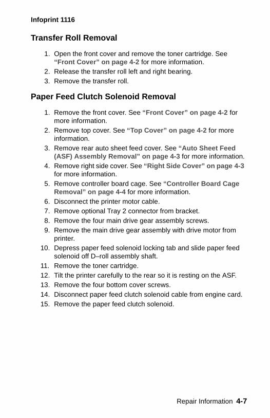
Infoprint 1116
Transfer Roll Removal
1. Open the front cover and remove the toner cartridge. See “Front Cover” on page 4-2 for more information.
2. Release the transfer roll left and right bearing. 3. Remove the transfer roll.
Paper Feed Clutch Solenoid Removal
1. Remove the front cover. See “Front Cover” on page 4-2 for more information.
2. Remove top cover. See “Top Cover” on page 4-2 for more information.
3. Remove rear auto sheet feed cover. See “Auto Sheet Feed (ASF) Assembly Removal” on page 4-3 for more information.
4. Remove right side cover. See “Right Side Cover” on page 4-3 for more information.
5. Remove controller board cage. See “Controller Board Cage Removal” on page 4-4 for more information.
6. Disconnect the printer motor cable. 7. Remove optional Tray 2 connector from bracket.8. Remove the four main drive gear assembly screws. 9. Remove the main drive gear assembly with drive motor from
printer. 10. Depress paper feed solenoid locking tab and slide paper feed
solenoid off D–roll assembly shaft. 11. Remove the toner cartridge. 12. Tilt the printer carefully to the rear so it is resting on the ASF. 13. Remove the four bottom cover screws. 14. Disconnect paper feed clutch solenoid cable from engine card. 15. Remove the paper feed clutch solenoid.
Repair Information 4-7
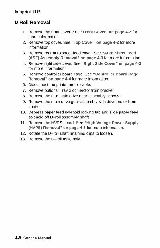
Infoprint 1116
D Roll Removal
1. Remove the front cover. See “Front Cover” on page 4-2 for more information.
2. Remove top cover. See “Top Cover” on page 4-2 for more information.
3. Remove rear auto sheet feed cover. See “Auto Sheet Feed (ASF) Assembly Removal” on page 4-3 for more information.
4. Remove right side cover. See “Right Side Cover” on page 4-3 for more information.
5. Remove controller board cage. See “Controller Board Cage Removal” on page 4-4 for more information.
6. Disconnect the printer motor cable. 7. Remove optional Tray 2 connector from bracket.8. Remove the four main drive gear assembly screws. 9. Remove the main drive gear assembly with drive motor from
printer. 10. Depress paper feed solenoid locking tab and slide paper feed
solenoid off D–roll assembly shaft. 11. Remove the HVPS board. See “High Voltage Power Supply
(HVPS) Removal” on page 4-5 for more information. 12. Rotate the D–roll shaft retaining clips to loosen. 13. Remove the D–roll assembly.
4-8 Service Manual
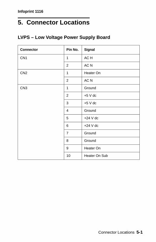
Infoprint 1116
5. Connector Locations
LVPS – Low Voltage Power Supply Board
Connector Pin No. Signal
CN1 1 AC H
2 AC N
CN2 1 Heater On
2 AC N
CN3 1 Ground
2 +5 V dc
3 +5 V dc
4 Ground
5 +24 V dc
6 +24 V dc
7 Ground
8 Ground
9 Heater On
10 Heater On Sub
Connector Locations 5-1
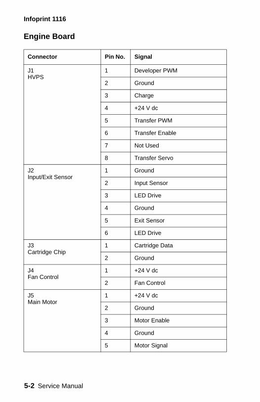
Infoprint 1116
Engine Board
Connector Pin No. Signal
J1 HVPS
1 Developer PWM
2 Ground
3 Charge
4 +24 V dc
5 Transfer PWM
6 Transfer Enable
7 Not Used
8 Transfer Servo
J2 Input/Exit Sensor
1 Ground
2 Input Sensor
3 LED Drive
4 Ground
5 Exit Sensor
6 LED Drive
J3 Cartridge Chip
1 Cartridge Data
2 Ground
J4 Fan Control
1 +24 V dc
2 Fan Control
J5 Main Motor
1 +24 V dc
2 Ground
3 Motor Enable
4 Ground
5 Motor Signal
5-2 Service Manual
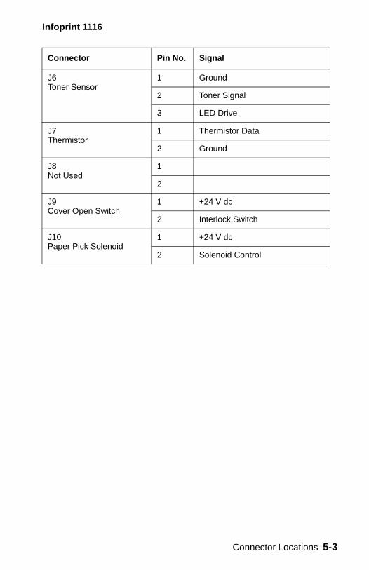
Infoprint 1116
J6Toner Sensor
1 Ground
2 Toner Signal
3 LED Drive
J7Thermistor
1 Thermistor Data
2 Ground
J8Not Used
1
2
J9Cover Open Switch
1 +24 V dc
2 Interlock Switch
J10Paper Pick Solenoid
1 +24 V dc
2 Solenoid Control
Connector Pin No. Signal
Connector Locations 5-3
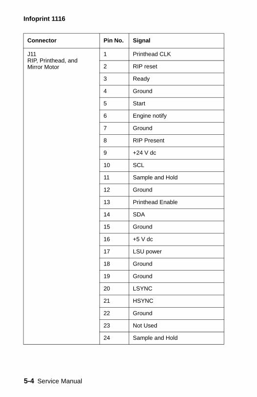
Infoprint 1116
J11RIP, Printhead, andMirror Motor
1 Printhead CLK
2 RIP reset
3 Ready
4 Ground
5 Start
6 Engine notify
7 Ground
8 RIP Present
9 +24 V dc
10 SCL
11 Sample and Hold
12 Ground
13 Printhead Enable
14 SDA
15 Ground
16 +5 V dc
17 LSU power
18 Ground
19 Ground
20 LSYNC
21 HSYNC
22 Ground
23 Not Used
24 Sample and Hold
Connector Pin No. Signal
5-4 Service Manual
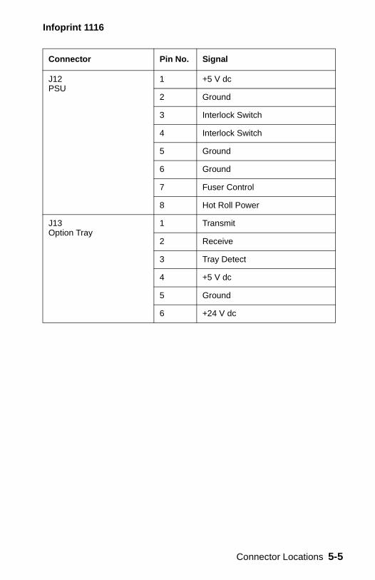
Infoprint 1116
J12PSU
1 +5 V dc
2 Ground
3 Interlock Switch
4 Interlock Switch
5 Ground
6 Ground
7 Fuser Control
8 Hot Roll Power
J13Option Tray
1 Transmit
2 Receive
3 Tray Detect
4 +5 V dc
5 Ground
6 +24 V dc
Connector Pin No. Signal
Connector Locations 5-5
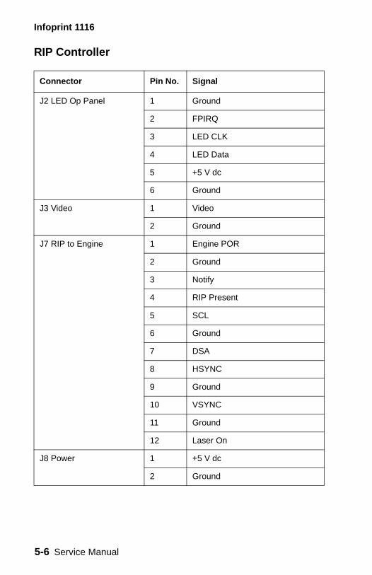
Infoprint 1116
RIP Controller
Connector Pin No. Signal
J2 LED Op Panel 1 Ground
2 FPIRQ
3 LED CLK
4 LED Data
5 +5 V dc
6 Ground
J3 Video 1 Video
2 Ground
J7 RIP to Engine 1 Engine POR
2 Ground
3 Notify
4 RIP Present
5 SCL
6 Ground
7 DSA
8 HSYNC
9 Ground
10 VSYNC
11 Ground
12 Laser On
J8 Power 1 +5 V dc
2 Ground
5-6 Service Manual
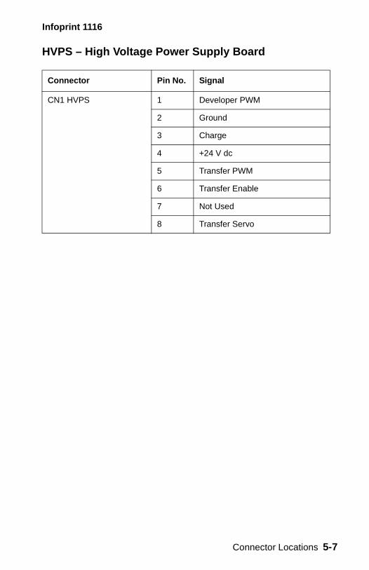
Infoprint 1116
HVPS – High Voltage Power Supply Board
Connector Pin No. Signal
CN1 HVPS 1 Developer PWM
2 Ground
3 Charge
4 +24 V dc
5 Transfer PWM
6 Transfer Enable
7 Not Used
8 Transfer Servo
Connector Locations 5-7
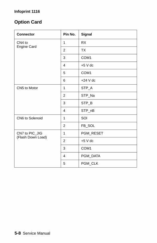
Infoprint 1116
Option Card
Connector Pin No. Signal
CN4 to Engine Card
1 RX
2 TX
3 COM1
4 +5 V dc
5 COM1
6 +24 V dc
CN5 to Motor 1 STP_A
2 STP_Na
3 STP_B
4 STP_nB
CN6 to Solenoid 1 SOl
2 FB_SOL
CN7 to PIC_JIG(Flash Down Load)
1 PGM_RESET
2 +5 V dc
3 COM1
4 PGM_DATA
5 PGM_CLK
5-8 Service Manual

Infoprint 1116
6. Preventive Maintenance
The Infoprint 1116 does not require preventive maintenance.
Preventive Maintenance 6-1

Infoprint 1116
6-2 Service Manual

Infoprint 1116
7. Parts Cata
How to Use this
• SIMILAR ASSEidentical parts, are shown by oother of the assdescription.
• AR: (As Requirquantity is not t
• NS: (Not Showpart is procurab
• PP: (Parts Packpart is containe
log
Parts Catalog
MBLIES: If two assemblies contain a majority of they are shown on the same list. Common parts ne index number. Parts peculiar to one or the emblies are listed separately and identified by
ed) in the Units column indicates that the he same for all machines.n) in the Asm-Index column indicates that the le but is not pictured in the illustration.et) in the parts description column indicates the d in a parts packet.
Parts Catalog 7-1
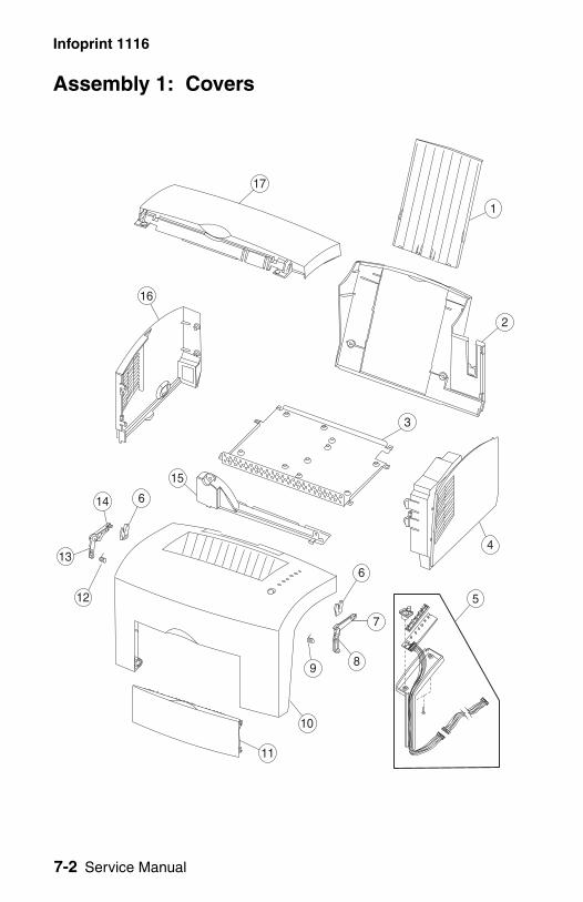
7-2 Service Manual
Infoprint 1116
Assembly 1: C
13
16
15
12
14 6
overs
3
7
5
9
2
6
4
8
1
17
10
11
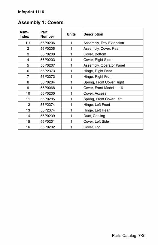
Infoprint 1116
Assembly 1: Cove
Asm-Index
Part Number
1-1 56P0206
2 56P0205
3 56P0208
4 56P0203
5 56P0207
6 56P2373
7 56P2373
8 56P0284
9 56P0068
10 56P0200
11 56P0285
12 56P2374
13 56P2374
14 56P0209
15 56P0201
16 56P0202
rs
Units Description
1 Assembly, Tray Extension
1 Assembly, Cover, Rear
1 Cover, Bottom
1 Cover, Right Side
1 Assembly, Operator Panel
1 Hinge, Right Rear
1 Hinge, Right Front
1 Spring, Front Cover Right
1 Cover, Front-Model 1116
1 Cover, Access
1 Spring, Front Cover Left
1 Hinge, Left Front
1 Hinge, Left Rear
1 Duct, Cooling
1 Cover, Left Side
1 Cover, Top
Parts Catalog 7-3
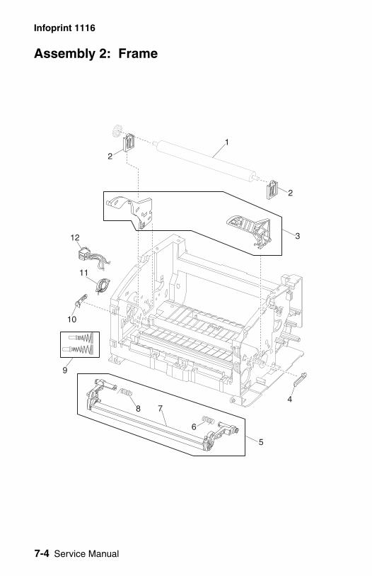
7-4 Service Manual
Infoprint 1116
Assembly 2: Fr
ame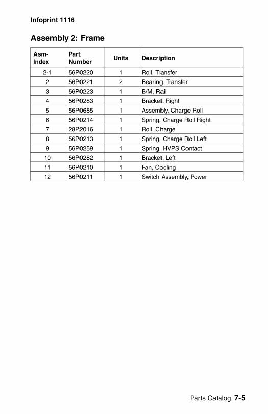
Infoprint 1116
Assembly 2: Fram
Asm-Index
Part Number
2-1 56P0220
2 56P0221
3 56P0223
4 56P0283
5 56P0685
6 56P0214
7 28P2016
8 56P0213
9 56P0259
10 56P0282
11 56P0210
12 56P0211
e
Units Description
1 Roll, Transfer
2 Bearing, Transfer
1 B/M, Rail
1 Bracket, Right
1 Assembly, Charge Roll
1 Spring, Charge Roll Right
1 Roll, Charge
1 Spring, Charge Roll Left
1 Spring, HVPS Contact
1 Bracket, Left
1 Fan, Cooling
1 Switch Assembly, Power
Parts Catalog 7-5
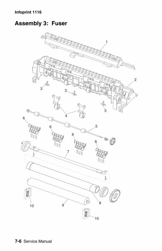
7-6 Service Manual
Infoprint 1116
Assembly 3: Fu
ser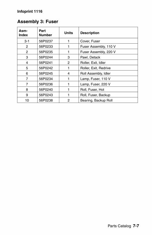
Infoprint 1116
Assembly 3: Fuse
Asm-Index
Part Number
3-1 56P0237
2 56P0233
2 56P0235
3 56P0244
4 56P0241
5 56P0242
6 56P0245
7 56P0234
7 56P0236
8 56P0240
9 56P0243
10 56P0238
r
Units Description
1 Cover, Fuser
1 Fuser Assembly, 110 V
1 Fuser Assembly, 220 V
3 Pawl, Detack
2 Roller, Exit, Idler
1 Roller, Exit, Redrive
4 Roll Assembly, Idler
1 Lamp, Fuser, 110 V
1 Lamp, Fuser, 220 V
1 Roll, Fuser, Hot
1 Roll, Fuser, Backup
2 Bearing, Backup Roll
Parts Catalog 7-7
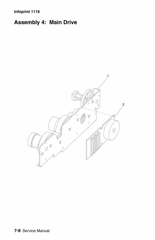
7-8 Service Manual
Infoprint 1116
Assembly 4: M
ain Drive
Infoprint 1116
Assembly 4: Main
Asm-Index
Part Number
4-1 56P2441
2 56P0248
Drive
Units Description
1 Gear Assembly, Drive
1 Motor, Drive
Parts Catalog 7-9
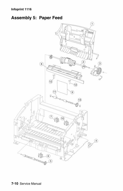
7-10 Service Manual
Infoprint 1116
Assembly 5: Pa
8
per Feed
3
11
7
13
9
2
10
4
12
1
12
5
6
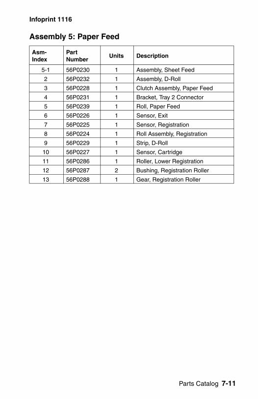
Infoprint 1116
Assembly 5: Pape
Asm-Index
Part Number
5-1 56P0230
2 56P0232
3 56P0228
4 56P0231
5 56P0239
6 56P0226
7 56P0225
8 56P0224
9 56P0229
10 56P0227
11 56P0286
12 56P0287
13 56P0288
r Feed
Units Description
1 Assembly, Sheet Feed
1 Assembly, D-Roll
1 Clutch Assembly, Paper Feed
1 Bracket, Tray 2 Connector
1 Roll, Paper Feed
1 Sensor, Exit
1 Sensor, Registration
1 Roll Assembly, Registration
1 Strip, D-Roll
1 Sensor, Cartridge
1 Roller, Lower Registration
2 Bushing, Registration Roller
1 Gear, Registration Roller
Parts Catalog 7-11
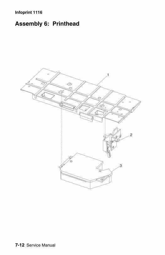
7-12 Service Manual
Infoprint 1116
Assembly 6: P
rinthead
Infoprint 1116
Assembly 6: Print
Asm-Index
Part Number
6-1 56P0247
2 56P0686
3 56P0246
head
Units Description
1 Plate, Printhead
1 Interlock, Cover
1 Assembly, Printhead
Parts Catalog 7-13
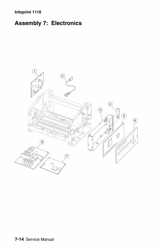
7-14 Service Manual
Infoprint 1116
Assembly 7: E
8
1
lectronics
5
2
6
4
3
7
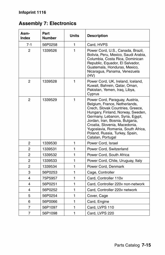
Infoprint 1116
Assembly 7: Elect
Asm-Index
Part Number
7-1 56P0258
2 1339526
2 1339528
2 1339529
2 1339530
2 1339531
2 1339532
2 1339533
2 1339534
3 56P0253
4 75P5957
4 56P0251
4 56P0252
5 56P0254
6 56P0066
7 56P1097
7 56P1098
ronics
Units Description
1 Card, HVPS
1 Power Cord, U.S., Canada, Brazil, Bolivia, Peru, Mexico, Saudi Arabia, Columbia, Costa Rica, Dominican Republic, Equador, El Salvador, Guatemala, Honduras, Mexico, Nicaragua, Panama, Venezuela (HV)
1 Power Cord, UK, Ireland, Iceland, Kuwait, Bahrein, Qatar, Oman, Pakistan, Yemen, Iraq, Libya, Cyprus
1 Power Cord, Paraguay, Austria, Belgium, France, Netherlands, Crech, Slovak Countries, Greece, Hungary, Finland, Norway, Sweden, Germany, Lebanon, Syria, Egypt, Jordan, Iran, Bosnia, Bulgaria, Croatia, Slovenia, Macedonia, Yugoslavia, Romania, South Africa, Poland, Russia, Turkey, Spain, Catalan, Portugal
1 Power Cord, Israel
1 Power Cord, Switzerland
1 Power Cord, South Africa
1 Power Cord, Chile, Uruguay, Italy
1 Power Cord, Denmark
1 Cage, Controller
1 Card, Controller 110v
1 Card, Controller 220v non-network
1 Card, Controller 220v network
1 Cover, Cage
1 Card, Engine
Parts Catalog 7-15
1 Card, LVPS 110
1 Card, LVPS 220
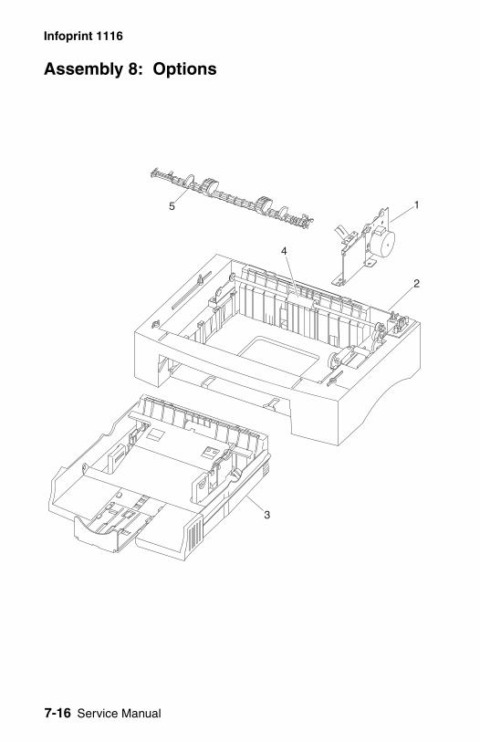
7-16 Service Manual
Infoprint 1116
Assembly 8: O
ptions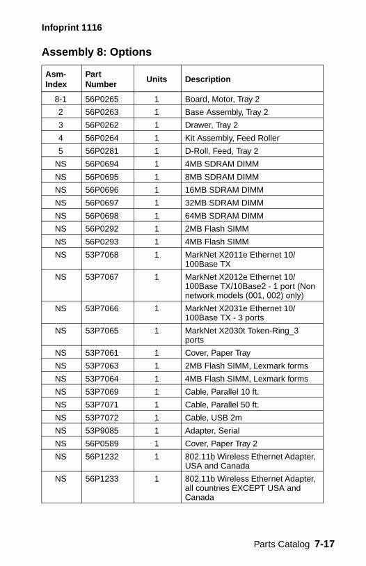
Infoprint 1116
Assembly 8: Optio
Asm-Index
Part Number
8-1 56P0265
2 56P0263
3 56P0262
4 56P0264
5 56P0281
NS 56P0694
NS 56P0695
NS 56P0696
NS 56P0697
NS 56P0698
NS 56P0292
NS 56P0293
NS 53P7068
NS 53P7067
NS 53P7066
NS 53P7065
NS 53P7061
NS 53P7063
NS 53P7064
NS 53P7069
NS 53P7071
NS 53P7072
NS 53P9085
NS 56P0589
NS 56P1232
NS 56P1233
ns
Units Description
1 Board, Motor, Tray 2
1 Base Assembly, Tray 2
1 Drawer, Tray 2
1 Kit Assembly, Feed Roller
1 D-Roll, Feed, Tray 2
1 4MB SDRAM DIMM
1 8MB SDRAM DIMM
1 16MB SDRAM DIMM
1 32MB SDRAM DIMM
1 64MB SDRAM DIMM
1 2MB Flash SIMM
1 4MB Flash SIMM
1 MarkNet X2011e Ethernet 10/100Base TX
1 MarkNet X2012e Ethernet 10/100Base TX/10Base2 - 1 port (Non network models (001, 002) only)
1 MarkNet X2031e Ethernet 10/100Base TX - 3 ports
1 MarkNet X2030t Token-Ring_3 ports
1 Cover, Paper Tray
1 2MB Flash SIMM, Lexmark forms
1 4MB Flash SIMM, Lexmark forms
1 Cable, Parallel 10 ft.
1 Cable, Parallel 50 ft.
1 Cable, USB 2m
1 Adapter, Serial
1 Cover, Paper Tray 2
Parts Catalog 7-17
1 802.11b Wireless Ethernet Adapter, USA and Canada
1 802.11b Wireless Ethernet Adapter, all countries EXCEPT USA and Canada
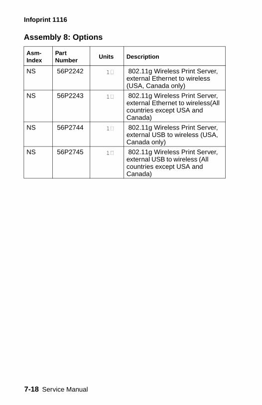
7-18 Service Manual
Infoprint 1116
NS 56P2242 1 802.11g Wireless Print Server, external Ethernet to wireless (USA, Canada only)
NS 56P2243 1 802.11g Wireless Print Server, external Ethernet to wireless(All countries except USA and Canada)
NS 56P2744 1 802.11g Wireless Print Server, external USB to wireless (USA, Canada only)
NS 56P2745 1 802.11g Wireless Print Server, external USB to wireless (All countries except USA and Canada)
Assembly 8: Options
Asm-Index
Part Number
Units Description

7-18 Service Manual
Infoprint 1116
Assembly 9: C
ables (no illustration)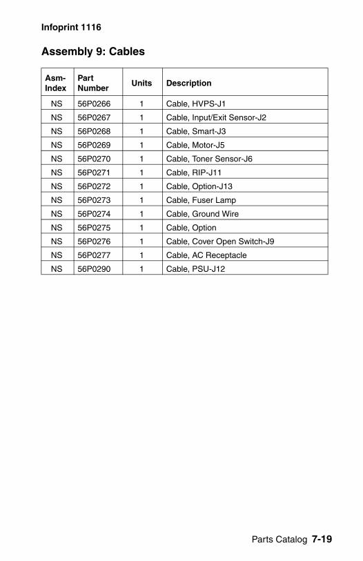
Infoprint 1116
Assembly 9: Cabl
Asm-Index
Part Number
U
NS 56P0266
NS 56P0267
NS 56P0268
NS 56P0269
NS 56P0270
NS 56P0271
NS 56P0272
NS 56P0273
NS 56P0274
NS 56P0275
NS 56P0276
NS 56P0277
NS 56P0290
es
nits Description
1 Cable, HVPS-J1
1 Cable, Input/Exit Sensor-J2
1 Cable, Smart-J3
1 Cable, Motor-J5
1 Cable, Toner Sensor-J6
1 Cable, RIP-J11
1 Cable, Option-J13
1 Cable, Fuser Lamp
1 Cable, Ground Wire
1 Cable, Option
1 Cable, Cover Open Switch-J9
1 Cable, AC Receptacle
1 Cable, PSU-J12
Parts Catalog 7-19

7-20 Service Manual
Infoprint 1116
Assembly 10: M
iscellaneous (no illustration)
Infoprint 1116
Assembly 10: Mis
Asm-Index
Part Number
U
NS 56P0278
NS 56P0279
NS 56P0280
NS Supply
cellaneous
nits Description
1 Ring, CS
1 Clamp, Mini
1 Parts Pack, Screws
1 Kit, Repack
Parts Catalog 7-21

7-22 Service Manual
Infoprint 1116
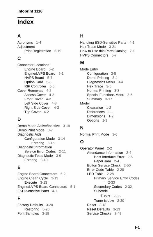
Infoprint 1116
Index
AAcronyms 1-4Adjustment
Print Registration 3-19
CConnector Locations
Engine Board 5-2Engine/LVPS Board 5-1HVPS Board 5-7Option Card 5-8RIP Controller 5-6
Cover Removals 4-2Access Cover 4-2Front Cover 4-2Left Side Cover 4-3Right Side Cover 4-3Top Cover 4-2
DDemo Mode Active/Inactive 3-19Demo Print Mode 3-7Diagnostic Aids
Configuration Mode 3-14Entering 3-15
Diagnostic InformationService Error Codes 2-11
Diagnostic Tests Mode 3-9Entering 3-10
EEngine Board Connectors 5-2Engine Clean Cycle 3-13
Execute 3-13Engine/LVPS Board Connectors 5-1ESD-Sensitive Parts 4-1
FFactory Defaults 3-20
Restoring 3-20Font Samples 3-18
HHandling ESD-Sensitive Parts 4-1Hex Trace Mode 3-21How to Use this Parts Catalog 7-1HVPS Connectors 5-7
MMode Entry
Configuration 3-5Demo Printing 3-4Diagnostics Menu 3-4Hex Trace 3-5Normal Printing 3-3Special Functions Menu 3-5Summary 3-17
ModelClearance 1-2Differences 1-1Dimensions 1-2Options 1-3
NNormal Print Mode 3-6
OOperator Panel 2-2
Attendance Information 2-4Host Interface Error 2-5Paper Jam 2-4
Button Service Check 2-50Error Code Table 2-28LED Table 2-28
Primary Service Error Codes2-33
Secondary Codes 2-32Subcode
fuser 2-35Toner is Low 2-30
Reset 3-18Reset Defaults 3-13Service Checks 2-49
I-1
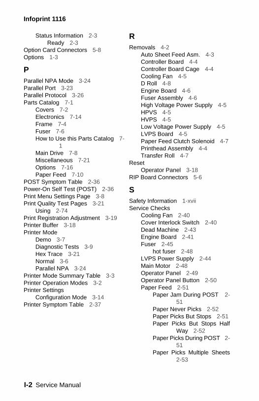
Infoprint 1116
Status Information 2-3Ready 2-3
Option Card Connectors 5-8Options 1-3
PParallel NPA Mode 3-24Parallel Port 3-23Parallel Protocol 3-26Parts Catalog 7-1
Covers 7-2Electronics 7-14Frame 7-4Fuser 7-6How to Use this Parts Catalog 7-
1Main Drive 7-8Miscellaneous 7-21Options 7-16Paper Feed 7-10
POST Symptom Table 2-36Power-On Self Test (POST) 2-36Print Menu Settings Page 3-8Print Quality Test Pages 3-21
Using 2-74Print Registration Adjustment 3-19Printer Buffer 3-18Printer Mode
Demo 3-7Diagnostic Tests 3-9Hex Trace 3-21Normal 3-6Parallel NPA 3-24
Printer Mode Summary Table 3-3Printer Operation Modes 3-2Printer Settings
Configuration Mode 3-14Printer Symptom Table 2-37
RRemovals 4-2
Auto Sheet Feed Asm. 4-3Controller Board 4-4Controller Board Cage 4-4Cooling Fan 4-5D Roll 4-8Engine Board 4-6Fuser Assembly 4-6High Voltage Power Supply 4-5HPVS 4-5HVPS 4-5Low Voltage Power Supply 4-5LVPS Board 4-5Paper Feed Clutch Solenoid 4-7Printhead Assembly 4-4Transfer Roll 4-7
ResetOperator Panel 3-18
RIP Board Connectors 5-6
SSafety Information 1-xviiService Checks
Cooling Fan 2-40Cover Interlock Switch 2-40Dead Machine 2-43Engine Board 2-41Fuser 2-45
hot fuser 2-48LVPS Power Supply 2-44Main Motor 2-48Operator Panel 2-49Operator Panel Button 2-50Paper Feed 2-51
Paper Jam During POST 2-51
Paper Never Picks 2-52Paper Picks But Stops 2-51Paper Picks But Stops Half
Way 2-52Paper Picks During POST 2-
51Paper Picks Multiple Sheets
2-53
I-2 Service Manual
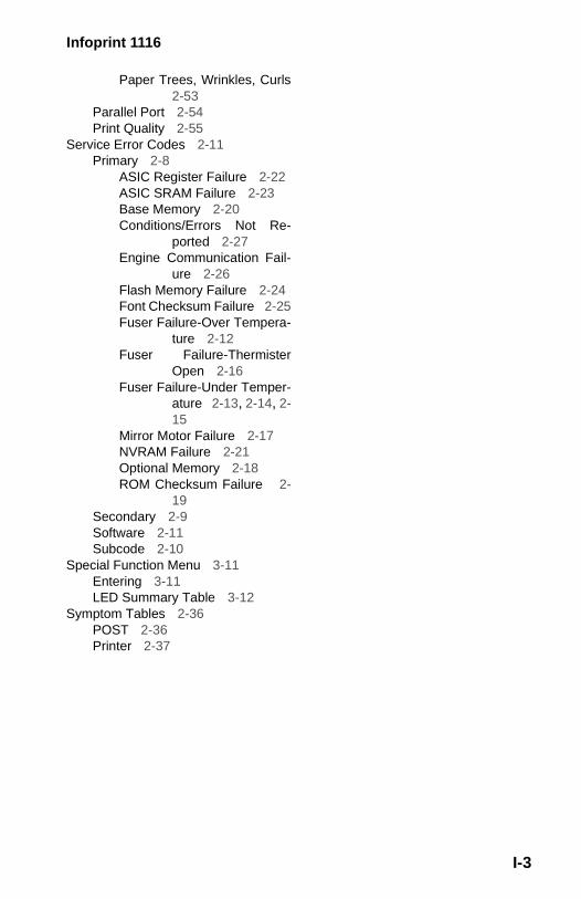
Infoprint 1116
Paper Trees, Wrinkles, Curls2-53
Parallel Port 2-54Print Quality 2-55
Service Error Codes 2-11Primary 2-8
ASIC Register Failure 2-22ASIC SRAM Failure 2-23Base Memory 2-20Conditions/Errors Not Re-
ported 2-27Engine Communication Fail-
ure 2-26Flash Memory Failure 2-24Font Checksum Failure 2-25Fuser Failure-Over Tempera-
ture 2-12Fuser Failure-Thermister
Open 2-16Fuser Failure-Under Temper-
ature 2-13, 2-14, 2-15
Mirror Motor Failure 2-17NVRAM Failure 2-21Optional Memory 2-18ROM Checksum Failure 2-
19Secondary 2-9Software 2-11Subcode 2-10
Special Function Menu 3-11Entering 3-11LED Summary Table 3-12
Symptom Tables 2-36POST 2-36Printer 2-37
I-3
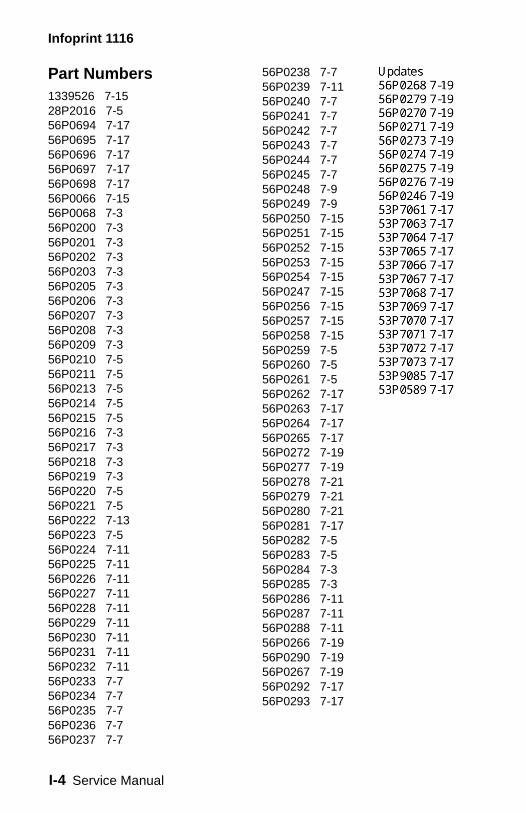
Infoprint 1116
Part Numbers1339526 7-1528P2016 7-556P0694 7-1756P0695 7-1756P0696 7-1756P0697 7-1756P0698 7-1756P0066 7-1556P0068 7-356P0200 7-356P0201 7-356P0202 7-356P0203 7-356P0205 7-356P0206 7-356P0207 7-356P0208 7-356P0209 7-356P0210 7-556P0211 7-556P0213 7-556P0214 7-556P0215 7-556P0216 7-356P0217 7-356P0218 7-356P0219 7-356P0220 7-556P0221 7-556P0222 7-1356P0223 7-556P0224 7-1156P0225 7-1156P0226 7-1156P0227 7-1156P0228 7-1156P0229 7-1156P0230 7-1156P0231 7-1156P0232 7-1156P0233 7-756P0234 7-756P0235 7-756P0236 7-756P0237 7-7
56P0238 7-756P0239 7-1156P0240 7-756P0241 7-756P0242 7-756P0243 7-756P0244 7-756P0245 7-756P0248 7-956P0249 7-956P0250 7-1556P0251 7-1556P0252 7-1556P0253 7-1556P0254 7-1556P0247 7-1556P0256 7-1556P0257 7-1556P0258 7-1556P0259 7-556P0260 7-556P0261 7-556P0262 7-1756P0263 7-1756P0264 7-1756P0265 7-1756P0272 7-1956P0277 7-1956P0278 7-2156P0279 7-2156P0280 7-2156P0281 7-1756P0282 7-556P0283 7-556P0284 7-356P0285 7-356P0286 7-1156P0287 7-1156P0288 7-1156P0266 7-1956P0290 7-1956P0267 7-1956P0292 7-1756P0293 7-17
I-4 Service Manual