ibm z/os v1r10 communications server tcp/ip implementation ... · ibm z/os v1r10 communications...
TRANSCRIPT

ibm.com/redbooks
Front cover
IBM z/OS V1R10 Communications ServerTCP/IP Implementation Volume 3:High Availability, Scalability, and Performance
Bill WhiteMike Ebbers
Valirio de Souza Braga Jr.WenHong Chen
Gwen DenteOctavio L. Ferreira
Marco GiudiciJoel Porterie
Micky ReichenbergAndi Wijaya
Discusses z/OS Communications Server TCP/IP high availability capabilities
Includes z/OS Communications Server TCP/IP high availability implementation examples
Provides insights into performance and tuning

International Technical Support Organization
IBM z/OS V1R10 Communications Server TCP/IP Implementation Volume 3: High Availability, Scalability, and Performance
May 2009
SG24-7698-00
© Copyright International Business Machines Corporation 2009. All rights reserved.Note to U.S. Government Users Restricted Rights -- Use, duplication or disclosure restricted by GSA ADP ScheduleContract with IBM Corp.
First Edition (May 2009)
This edition applies to Version 1, Release 10, of z/OS Communications Server.
Note: Before using this information and the product it supports, read the information in “Notices” on page vii.

Contents
Notices . . . . . . . . . . . . . . . . . . . . . . . . . . . . . . . . . . . . . . . . . . . . . . . . . . . . . . . . . . . . . . . . . viiTrademarks . . . . . . . . . . . . . . . . . . . . . . . . . . . . . . . . . . . . . . . . . . . . . . . . . . . . . . . . . . . . . viii
Preface . . . . . . . . . . . . . . . . . . . . . . . . . . . . . . . . . . . . . . . . . . . . . . . . . . . . . . . . . . . . . . . . . ixThe team that wrote this book . . . . . . . . . . . . . . . . . . . . . . . . . . . . . . . . . . . . . . . . . . . . . . . . .xBecome a published author . . . . . . . . . . . . . . . . . . . . . . . . . . . . . . . . . . . . . . . . . . . . . . . . . . xiiComments welcome. . . . . . . . . . . . . . . . . . . . . . . . . . . . . . . . . . . . . . . . . . . . . . . . . . . . . . . . xii
Chapter 1. Introduction to z/OS Communications Serverhigh availability technologies . . . . . . . . . . . . . . . . . . . . . . . . . . . . . . . . . . . . . 1
1.1 Overview of high availability . . . . . . . . . . . . . . . . . . . . . . . . . . . . . . . . . . . . . . . . . . . . . . 21.2 Fundamental technologies for z/OS TCP/IP availability . . . . . . . . . . . . . . . . . . . . . . . . . 2
1.2.1 Single z/OS system availability . . . . . . . . . . . . . . . . . . . . . . . . . . . . . . . . . . . . . . . . 21.2.2 z/OS Parallel Sysplex availability . . . . . . . . . . . . . . . . . . . . . . . . . . . . . . . . . . . . . . 31.2.3 Virtual IP addressing. . . . . . . . . . . . . . . . . . . . . . . . . . . . . . . . . . . . . . . . . . . . . . . . 41.2.4 z/OS network connectivity and dynamic routing . . . . . . . . . . . . . . . . . . . . . . . . . . . 51.2.5 Single-instance and multiple-instance applications. . . . . . . . . . . . . . . . . . . . . . . . . 71.2.6 Balancing workload across multiple application instances . . . . . . . . . . . . . . . . . . . 8
1.3 Quick start table . . . . . . . . . . . . . . . . . . . . . . . . . . . . . . . . . . . . . . . . . . . . . . . . . . . . . . 11
Chapter 2. Virtual IP addressing . . . . . . . . . . . . . . . . . . . . . . . . . . . . . . . . . . . . . . . . . . . 132.1 Basic concepts of Virtual IP Addressing . . . . . . . . . . . . . . . . . . . . . . . . . . . . . . . . . . . . 14
2.1.1 Application availability modes . . . . . . . . . . . . . . . . . . . . . . . . . . . . . . . . . . . . . . . . 162.1.2 DVIPA and distributed DVIPA. . . . . . . . . . . . . . . . . . . . . . . . . . . . . . . . . . . . . . . . 172.1.3 VIPARoute function. . . . . . . . . . . . . . . . . . . . . . . . . . . . . . . . . . . . . . . . . . . . . . . . 25
2.2 Importance of VIPA . . . . . . . . . . . . . . . . . . . . . . . . . . . . . . . . . . . . . . . . . . . . . . . . . . . . 262.3 Timing of DVIPA activation . . . . . . . . . . . . . . . . . . . . . . . . . . . . . . . . . . . . . . . . . . . . . . 27
2.3.1 DVIPA definitions . . . . . . . . . . . . . . . . . . . . . . . . . . . . . . . . . . . . . . . . . . . . . . . . . 272.3.2 DVIPA commands. . . . . . . . . . . . . . . . . . . . . . . . . . . . . . . . . . . . . . . . . . . . . . . . . 31
2.4 Dynamic VIPA example . . . . . . . . . . . . . . . . . . . . . . . . . . . . . . . . . . . . . . . . . . . . . . . . 342.4.1 Advantages . . . . . . . . . . . . . . . . . . . . . . . . . . . . . . . . . . . . . . . . . . . . . . . . . . . . . . 352.4.2 Dependencies . . . . . . . . . . . . . . . . . . . . . . . . . . . . . . . . . . . . . . . . . . . . . . . . . . . . 352.4.3 Implementation . . . . . . . . . . . . . . . . . . . . . . . . . . . . . . . . . . . . . . . . . . . . . . . . . . . 352.4.4 Automatic VIPA takeover and takeback . . . . . . . . . . . . . . . . . . . . . . . . . . . . . . . . 38
Chapter 3. VIPA without dynamic routing . . . . . . . . . . . . . . . . . . . . . . . . . . . . . . . . . . . . 453.1 Basic concepts . . . . . . . . . . . . . . . . . . . . . . . . . . . . . . . . . . . . . . . . . . . . . . . . . . . . . . . 46
3.1.1 ARP takeover . . . . . . . . . . . . . . . . . . . . . . . . . . . . . . . . . . . . . . . . . . . . . . . . . . . . 473.2 High availability without dynamic routing . . . . . . . . . . . . . . . . . . . . . . . . . . . . . . . . . . . 51
3.2.1 Implementation . . . . . . . . . . . . . . . . . . . . . . . . . . . . . . . . . . . . . . . . . . . . . . . . . . . 523.2.2 Verification . . . . . . . . . . . . . . . . . . . . . . . . . . . . . . . . . . . . . . . . . . . . . . . . . . . . . . 55
3.3 High availability scenarios. . . . . . . . . . . . . . . . . . . . . . . . . . . . . . . . . . . . . . . . . . . . . . . 573.3.1 Adapter interface failure . . . . . . . . . . . . . . . . . . . . . . . . . . . . . . . . . . . . . . . . . . . . 573.3.2 Application movement. . . . . . . . . . . . . . . . . . . . . . . . . . . . . . . . . . . . . . . . . . . . . . 583.3.3 Stack failure . . . . . . . . . . . . . . . . . . . . . . . . . . . . . . . . . . . . . . . . . . . . . . . . . . . . . 61
3.4 Debugging tips . . . . . . . . . . . . . . . . . . . . . . . . . . . . . . . . . . . . . . . . . . . . . . . . . . . . . . . 62
Chapter 4. VIPA with dynamic routing. . . . . . . . . . . . . . . . . . . . . . . . . . . . . . . . . . . . . . . 654.1 Basic concepts of high availability using dynamic routing. . . . . . . . . . . . . . . . . . . . . . . 66
© Copyright IBM Corp. 2009. All rights reserved. iii

4.1.1 Dynamic routing and OMPROUTE . . . . . . . . . . . . . . . . . . . . . . . . . . . . . . . . . . . . 664.1.2 Advertisement of VIPA addresses . . . . . . . . . . . . . . . . . . . . . . . . . . . . . . . . . . . . 664.1.3 Multiple links between IP nodes and LPARs. . . . . . . . . . . . . . . . . . . . . . . . . . . . . 69
4.2 Design example for dynamic routing. . . . . . . . . . . . . . . . . . . . . . . . . . . . . . . . . . . . . . . 744.2.1 PROFILE statements . . . . . . . . . . . . . . . . . . . . . . . . . . . . . . . . . . . . . . . . . . . . . . 754.2.2 OMPROUTE definitions . . . . . . . . . . . . . . . . . . . . . . . . . . . . . . . . . . . . . . . . . . . . 774.2.3 Router definitions . . . . . . . . . . . . . . . . . . . . . . . . . . . . . . . . . . . . . . . . . . . . . . . . . 794.2.4 Verification . . . . . . . . . . . . . . . . . . . . . . . . . . . . . . . . . . . . . . . . . . . . . . . . . . . . . . 80
4.3 High availability scenarios. . . . . . . . . . . . . . . . . . . . . . . . . . . . . . . . . . . . . . . . . . . . . . . 834.3.1 Adapter interface failure . . . . . . . . . . . . . . . . . . . . . . . . . . . . . . . . . . . . . . . . . . . . 844.3.2 Application movement using VIPADEFINE. . . . . . . . . . . . . . . . . . . . . . . . . . . . . . 874.3.3 Stack failure scenario using VIPADEFINE and VIPABACKUP. . . . . . . . . . . . . . . 91
Chapter 5. Internal application workload balancing . . . . . . . . . . . . . . . . . . . . . . . . . . . 955.1 Basic concepts of internal application workload balancing . . . . . . . . . . . . . . . . . . . . . . 96
5.1.1 Sysplex Distributor—principles of operation . . . . . . . . . . . . . . . . . . . . . . . . . . . . . 975.1.2 Sysplex Distributor and Quality of Service policy . . . . . . . . . . . . . . . . . . . . . . . . . 985.1.3 Portsharing . . . . . . . . . . . . . . . . . . . . . . . . . . . . . . . . . . . . . . . . . . . . . . . . . . . . . . 995.1.4 Optimized routing . . . . . . . . . . . . . . . . . . . . . . . . . . . . . . . . . . . . . . . . . . . . . . . . 1015.1.5 Improved workload distribution . . . . . . . . . . . . . . . . . . . . . . . . . . . . . . . . . . . . . . 1025.1.6 Unreachable DVIPA Detection and Recovery. . . . . . . . . . . . . . . . . . . . . . . . . . . 118
5.2 Design and implementation examples . . . . . . . . . . . . . . . . . . . . . . . . . . . . . . . . . . . . 1195.2.1 Sysplex Distributor using server-specific WLM. . . . . . . . . . . . . . . . . . . . . . . . . . 1195.2.2 Sysplex Distributor using BASEWLM . . . . . . . . . . . . . . . . . . . . . . . . . . . . . . . . . 1295.2.3 Sysplex Distributor using round-robin . . . . . . . . . . . . . . . . . . . . . . . . . . . . . . . . . 1315.2.4 Sysplex Distributor using WEIGHTEDActive method . . . . . . . . . . . . . . . . . . . . . 1335.2.5 Portsharing using SHAREPORTWLM . . . . . . . . . . . . . . . . . . . . . . . . . . . . . . . . 1365.2.6 Sysplex Distributor using Unreachable DVIPA Detection and Recovery . . . . . . 142
5.3 Problem determination . . . . . . . . . . . . . . . . . . . . . . . . . . . . . . . . . . . . . . . . . . . . . . . . 156
Chapter 6. External application workload balancing . . . . . . . . . . . . . . . . . . . . . . . . . . 1596.1 Basic concepts of external load balancing . . . . . . . . . . . . . . . . . . . . . . . . . . . . . . . . . 160
6.1.1 Understanding directed mode load balancing. . . . . . . . . . . . . . . . . . . . . . . . . . . 1606.1.2 z/OS Load Balancer Advisor . . . . . . . . . . . . . . . . . . . . . . . . . . . . . . . . . . . . . . . . 1626.1.3 Server/Application State Protocol (SASP) . . . . . . . . . . . . . . . . . . . . . . . . . . . . . 1646.1.4 External load balancer without LBA/SASP . . . . . . . . . . . . . . . . . . . . . . . . . . . . . 1666.1.5 External load balancer with LBA/SASP. . . . . . . . . . . . . . . . . . . . . . . . . . . . . . . . 1676.1.6 Importance of external application workload balancing . . . . . . . . . . . . . . . . . . . 167
6.2 External load balancer without LBA/SASP . . . . . . . . . . . . . . . . . . . . . . . . . . . . . . . . . 1686.2.1 External load balancer without LBA/SASP implementation . . . . . . . . . . . . . . . . 170
6.3 External load balancer with LBA/SASP. . . . . . . . . . . . . . . . . . . . . . . . . . . . . . . . . . . . 1806.3.1 TLS/SSL for z/OS Load Balancing Advisor. . . . . . . . . . . . . . . . . . . . . . . . . . . . . 1816.3.2 External load balancer with LBA/SASP implementation . . . . . . . . . . . . . . . . . . . 182
Chapter 7. Intra-sysplex workload balancing . . . . . . . . . . . . . . . . . . . . . . . . . . . . . . . . 2017.1 Optimizing SD intra-sysplex load balancing . . . . . . . . . . . . . . . . . . . . . . . . . . . . . . . . 202
7.1.1 Current connections from WebSphere Application Server to EIS. . . . . . . . . . . . 2027.1.2 Optimized multitier application workload balancing . . . . . . . . . . . . . . . . . . . . . . 204
7.2 Optimized multitier z/OS SD load balancing . . . . . . . . . . . . . . . . . . . . . . . . . . . . . . . . 2057.2.1 Basic concepts and general information . . . . . . . . . . . . . . . . . . . . . . . . . . . . . . . 2057.2.2 Applied system configuration for optimized load balancing . . . . . . . . . . . . . . . . 2077.2.3 Request flow between client, WebSphere Application Server and application
endpoint . . . . . . . . . . . . . . . . . . . . . . . . . . . . . . . . . . . . . . . . . . . . . . . . . . . . . . . 2097.2.4 OPTLOCAL test cases . . . . . . . . . . . . . . . . . . . . . . . . . . . . . . . . . . . . . . . . . . . . 211
iv IBM z/OS V1R10 Communications Server TCP/IP Implementation Volume 3: High Availability, Scalability, and Performance

7.3 WLM reporting abnormal conditions . . . . . . . . . . . . . . . . . . . . . . . . . . . . . . . . . . . . . . 2317.3.1 Situation of current workload distribution decisions . . . . . . . . . . . . . . . . . . . . . . 2327.3.2 Calculation of WLM weight and TSR . . . . . . . . . . . . . . . . . . . . . . . . . . . . . . . . . 2327.3.3 WLM interface for abnormal transactions and health status . . . . . . . . . . . . . . . . 234
Chapter 8. Performance and tuning . . . . . . . . . . . . . . . . . . . . . . . . . . . . . . . . . . . . . . . 2398.1 General performance considerations . . . . . . . . . . . . . . . . . . . . . . . . . . . . . . . . . . . . . 2408.2 TCP/IP configuration files . . . . . . . . . . . . . . . . . . . . . . . . . . . . . . . . . . . . . . . . . . . . . . 242
8.2.1 MTU considerations . . . . . . . . . . . . . . . . . . . . . . . . . . . . . . . . . . . . . . . . . . . . . . 2428.2.2 OSA-Express2 LAN idle timer function . . . . . . . . . . . . . . . . . . . . . . . . . . . . . . . . 2468.2.3 Tracing . . . . . . . . . . . . . . . . . . . . . . . . . . . . . . . . . . . . . . . . . . . . . . . . . . . . . . . . 248
8.3 z/OS UNIX System Services tuning . . . . . . . . . . . . . . . . . . . . . . . . . . . . . . . . . . . . . . 2498.4 Storage requirements . . . . . . . . . . . . . . . . . . . . . . . . . . . . . . . . . . . . . . . . . . . . . . . . . 249
8.4.1 TCP and UDP buffer sizes . . . . . . . . . . . . . . . . . . . . . . . . . . . . . . . . . . . . . . . . . 2498.4.2 Communications Storage Manager use of storage. . . . . . . . . . . . . . . . . . . . . . . 2508.4.3 VTAM buffer settings . . . . . . . . . . . . . . . . . . . . . . . . . . . . . . . . . . . . . . . . . . . . . 253
8.5 Application performance and capacity . . . . . . . . . . . . . . . . . . . . . . . . . . . . . . . . . . . . 2548.5.1 Telnet (TN3270) capacity planning . . . . . . . . . . . . . . . . . . . . . . . . . . . . . . . . . . . 2548.5.2 FTP tuning . . . . . . . . . . . . . . . . . . . . . . . . . . . . . . . . . . . . . . . . . . . . . . . . . . . . . 2558.5.3 FTP capacity planning . . . . . . . . . . . . . . . . . . . . . . . . . . . . . . . . . . . . . . . . . . . . 255
8.6 z/OS Communications Server TCP/IP performance enhancements highlights . . . . . 2568.7 TCP/IP performance quick checklist . . . . . . . . . . . . . . . . . . . . . . . . . . . . . . . . . . . . . . 2588.8 Health Checker . . . . . . . . . . . . . . . . . . . . . . . . . . . . . . . . . . . . . . . . . . . . . . . . . . . . . . 259
8.8.1 What is a check. . . . . . . . . . . . . . . . . . . . . . . . . . . . . . . . . . . . . . . . . . . . . . . . . . 2598.8.2 Health Monitor checks with commands. . . . . . . . . . . . . . . . . . . . . . . . . . . . . . . . 2618.8.3 Health Monitor checks with GUI . . . . . . . . . . . . . . . . . . . . . . . . . . . . . . . . . . . . . 262
Appendix A. HiperSockets Multiple Write. . . . . . . . . . . . . . . . . . . . . . . . . . . . . . . . . . . 267The environment used for our tests . . . . . . . . . . . . . . . . . . . . . . . . . . . . . . . . . . . . . . . . . . 268
Appendix B. Our implementation environment . . . . . . . . . . . . . . . . . . . . . . . . . . . . . . 277The environment used for all four books . . . . . . . . . . . . . . . . . . . . . . . . . . . . . . . . . . . . . . 278
Our focus for this book . . . . . . . . . . . . . . . . . . . . . . . . . . . . . . . . . . . . . . . . . . . . . . . . . 280
Related publications . . . . . . . . . . . . . . . . . . . . . . . . . . . . . . . . . . . . . . . . . . . . . . . . . . . . 281IBM Redbooks . . . . . . . . . . . . . . . . . . . . . . . . . . . . . . . . . . . . . . . . . . . . . . . . . . . . . . . . . . 281Other publications . . . . . . . . . . . . . . . . . . . . . . . . . . . . . . . . . . . . . . . . . . . . . . . . . . . . . . . 281Online resources . . . . . . . . . . . . . . . . . . . . . . . . . . . . . . . . . . . . . . . . . . . . . . . . . . . . . . . . 282How to get IBM Redbooks publications . . . . . . . . . . . . . . . . . . . . . . . . . . . . . . . . . . . . . . . 283Help from IBM . . . . . . . . . . . . . . . . . . . . . . . . . . . . . . . . . . . . . . . . . . . . . . . . . . . . . . . . . . 283
Index . . . . . . . . . . . . . . . . . . . . . . . . . . . . . . . . . . . . . . . . . . . . . . . . . . . . . . . . . . . . . . . . . 285
Contents v

vi IBM z/OS V1R10 Communications Server TCP/IP Implementation Volume 3: High Availability, Scalability, and Performance

Notices
This information was developed for products and services offered in the U.S.A.
IBM may not offer the products, services, or features discussed in this document in other countries. Consult your local IBM representative for information on the products and services currently available in your area. Any reference to an IBM product, program, or service is not intended to state or imply that only that IBM product, program, or service may be used. Any functionally equivalent product, program, or service that does not infringe any IBM intellectual property right may be used instead. However, it is the user's responsibility to evaluate and verify the operation of any non-IBM product, program, or service.
IBM may have patents or pending patent applications covering subject matter described in this document. The furnishing of this document does not give you any license to these patents. You can send license inquiries, in writing, to: IBM Director of Licensing, IBM Corporation, North Castle Drive, Armonk, NY 10504-1785 U.S.A.
The following paragraph does not apply to the United Kingdom or any other country where such provisions are inconsistent with local law: INTERNATIONAL BUSINESS MACHINES CORPORATION PROVIDES THIS PUBLICATION "AS IS" WITHOUT WARRANTY OF ANY KIND, EITHER EXPRESS OR IMPLIED, INCLUDING, BUT NOT LIMITED TO, THE IMPLIED WARRANTIES OF NON-INFRINGEMENT, MERCHANTABILITY OR FITNESS FOR A PARTICULAR PURPOSE. Some states do not allow disclaimer of express or implied warranties in certain transactions, therefore, this statement may not apply to you.
This information could include technical inaccuracies or typographical errors. Changes are periodically made to the information herein; these changes will be incorporated in new editions of the publication. IBM may make improvements and/or changes in the product(s) and/or the program(s) described in this publication at any time without notice.
Any references in this information to non-IBM Web sites are provided for convenience only and do not in any manner serve as an endorsement of those Web sites. The materials at those Web sites are not part of the materials for this IBM product and use of those Web sites is at your own risk.
IBM may use or distribute any of the information you supply in any way it believes appropriate without incurring any obligation to you.
Information concerning non-IBM products was obtained from the suppliers of those products, their published announcements or other publicly available sources. IBM has not tested those products and cannot confirm the accuracy of performance, compatibility or any other claims related to non-IBM products. Questions on the capabilities of non-IBM products should be addressed to the suppliers of those products.
This information contains examples of data and reports used in daily business operations. To illustrate them as completely as possible, the examples include the names of individuals, companies, brands, and products. All of these names are fictitious and any similarity to the names and addresses used by an actual business enterprise is entirely coincidental.
COPYRIGHT LICENSE:
This information contains sample application programs in source language, which illustrate programming techniques on various operating platforms. You may copy, modify, and distribute these sample programs in any form without payment to IBM, for the purposes of developing, using, marketing or distributing application programs conforming to the application programming interface for the operating platform for which the sample programs are written. These examples have not been thoroughly tested under all conditions. IBM, therefore, cannot guarantee or imply reliability, serviceability, or function of these programs.
© Copyright IBM Corp. 2009. All rights reserved. vii

Trademarks
IBM, the IBM logo, and ibm.com are trademarks or registered trademarks of International Business Machines Corporation in the United States, other countries, or both. These and other IBM trademarked terms are marked on their first occurrence in this information with the appropriate symbol (® or ™), indicating US registered or common law trademarks owned by IBM at the time this information was published. Such trademarks may also be registered or common law trademarks in other countries. A current list of IBM trademarks is available on the Web at http://www.ibm.com/legal/copytrade.shtml
The following terms are trademarks of the International Business Machines Corporation in the United States, other countries, or both:
CICS®DB2®ESCON®FICON®HiperSockets™IBM®OMEGAMON®
Parallel Sysplex®RACF®Redbooks®Redbooks (logo) ®System z10™System z9®System z®
Tivoli®VTAM®WebSphere®z/OS®z9®
The following terms are trademarks of other companies:
Catalyst, the AMD Arrow logo, and combinations thereof, are trademarks of Advanced Micro Devices, Inc.
Java, and all Java-based trademarks are trademarks of Sun Microsystems, Inc. in the United States, other countries, or both.
Internet Explorer, MS, Windows, and the Windows logo are trademarks of Microsoft Corporation in the United States, other countries, or both.
UNIX is a registered trademark of The Open Group in the United States and other countries.
Other company, product, or service names may be trademarks or service marks of others.
viii IBM z/OS V1R10 Communications Server TCP/IP Implementation Volume 3: High Availability, Scalability, and Performance

Preface
For more than 40 years, IBM® mainframes have supported an extraordinary portion of the world’s computing work, providing centralized corporate databases and mission-critical enterprise-wide applications. The IBM System z®, the latest generation of the IBM distinguished family of mainframe systems, has come a long way from its IBM System/360 heritage. Likewise, its IBM z/OS® operating system is far superior to its predecessors, providing, among many other capabilities, world-class, state-of-the-art, support for the TCP/IP Internet protocol suite.
TCP/IP is a large and evolving collection of communication protocols managed by the Internet Engineering Task Force (IETF), an open, volunteer, organization. Because of its openness, the TCP/IP protocol suite has become the foundation for the set of technologies that form the basis of the Internet. The convergence of IBM mainframe capabilities with Internet technology, connectivity, and standards (particularly TCP/IP) is dramatically changing the face of information technology and driving requirements for ever more secure, scalable, and highly available mainframe TCP/IP implementations.
The IBM z/OS Communications Server TCP/IP Implementation series provides understandable, step-by-step guidance about how to enable the most commonly used and important functions of z/OS Communications Server TCP/IP.
In this IBM Redbooks® publication, we begin with a discussion of Virtual IP Addressing (VIPA), a TCP/IP high-availability approach that was introduced by the z/OS Communications Server. We then show how to use VIPA for high availability, both with and without a dynamic routing protocol. We also discuss a number of different workload balancing approaches that you can use with the z/OS Communications Server. We also explain the optimized Sysplex Distributor intra-sysplex load balancing. This function represents improved multitier application support using optimized local connections together with weight values from extended Workload Manager (WLM) interfaces. Finally, we highlight the most important tuning parameters and suggest parameter values that we observed to maximize performance in many client installations.
For more specific information about z/OS Communications Server base functions, standard applications, and security, refer to the other volumes in the series:
� IBM z/OS V1R10 Communications Server TCP/IP Implementation Volume 1: Base Functions, Connectivity, and Routing, SG24-7696
� IBM z/OS V1R10 Communications Server TCP/IP Implementation Volume 2: Standard Applications, SG24-7697
� IBM z/OS V1R10 Communications Server TCP/IP Implementation Volume 4: Security and Policy-Based Networking, SG24-7699
Note: In this book, we use the terms internal and external application workload balancing to refer to approaches where the decision as to which application instance should received a given connection request is made within the sysplex environment (such as by Sysplex Distributor) or outside of it (using a separate, external, workload balancing solution), respectively.
© Copyright IBM Corp. 2009. All rights reserved. ix

For comprehensive descriptions of the individual parameters for setting up and using the functions described in this book, along with step-by-step checklists and supporting examples, refer to the following publications:
� z/OS Communications Server: IP Configuration Guide, SC31-8775
� z/OS Communications Server: IP Configuration Reference, SC31-8776
� z/OS Communications Server: IP User’s Guide and Commands, SC31-8780
This book does not duplicate the information in those publications. Instead, it complements them with practical implementation scenarios that can be useful in your environment. To determine at what level a specific function was introduced, refer to z/OS Communications Server: New Function Summary, GC31-8771. For complete details, we encourage you to review the documents referred to in “Related publications” on page 281.
The team that wrote this book
This book was produced by a team of specialists from around the world working at the International Technical Support Organization (ITSO), Poughkeepsie Center.
Bill White is a Project Leader and Senior Networking Specialist at the ITSO, Poughkeepsie Center.
Mike Ebbers is a Project Leader and Consulting IT Specialist at the ITSO, Poughkeepsie Center. He has worked for IBM for 35 years, and at one time he was an SNA Specialist.
Valirio de Souza Braga Jr. is a Senior IT Specialist in Brazil working for the IBM Support Center. He has 10 years of experience in networking with areas of expertise, including VTAM®, TCP/IP, z/OS Communications Server, and OSA. His current responsibilities include designing mainframe IP connectivity solutions, designing inter-company Enterprise Extender configurations, and assisting customers with high availability data center implementations. Valirio has also co-authored other IBM Redbooks publications.
WenHong Chen is a Senior IT Specialist in IBM Global Services, China. For 11 years WenHong has provided technical support to mainframe customers in southern China for system architecture design, implementation, and performance tuning for z/OS, as well as major subsystems (z/OS Communications Server, WLM, RACF®, DFSMS) and BCRS services. Her areas of expertise in z/OS Communications Server include VTAM/APPN, TCP/IP, and Enterprise Extender.
Gwen Dente is a Consulting IT Specialist with IBM Advanced Technical Support at the Washington Systems Center in Gaithersburg, Maryland, U. S. She focuses on System z networking and security, assisting customers and the IBM technical community with cross-platform integration and network design. Gwen presents frequently at SHARE and other IBM technical conferences and has shared authorship of multiple IBM Redbooks publications.
Octavio L. Ferreira is a Senior IT Specialist in IBM Brazil. He has 28 years of experience in IBM software support. His areas of expertise include z/OS Communications Server, SNA and TCP/IP, and Communications Server on all platforms. For the last 10 years, Octavio has worked at the Area Program Support Group, providing guidance and support to clients and designing networking solutions such as SNA/TCP/IP Integration, z/OS Connectivity, Enterprise Extender design and implementation, and SNA-to-APPN migration. He has also co-authored other IBM Redbooks publications.
x IBM z/OS V1R10 Communications Server TCP/IP Implementation Volume 3: High Availability, Scalability, and Performance

Marco Giudici is an IT Architect in IBM Australia. He has 20 years experience in supporting IBM mainframes in different areas and different countries, including ten years in networking. His current responsibilities include designing mainframe and non-mainframe solutions for IBM Australia Strategic Outsourcing customers, mainly in the financial and government sectors.
Joel Porterie is a Senior IT Specialist who has been with IBM France for over 30 years. He works for Network and Channel Connectivity Services in the EMEA Product Support Group. His areas of expertise include z/OS, TCP/IP, VTAM, OSA-Express, and Parallel Sysplex®. Joel has taught OSA-Express and FICON® problem determination classes and has provided onsite assistance in these areas in numerous countries. He has also co-authored many other IBM Redbooks publications.
Micky Reichenberg is an independent consultant with more than 35 years of experience in mainframe networking. He specializes in mainframe TCP/IP, SNA, open systems connectivity to the mainframe, Enterprise Extender design and implementation. Prior to becoming a consultant, Micky was a systems programmer with IBM in Israel for 17 years. During his assignment with the ITSO at the Raleigh Center, he published five networking-related IBM Redbooks publications. He holds a Bachelor’s degree in Aeronautical Engineering from the Techion Israel Institute of Technology. Micky has also co-authored other IBM Redbooks publications.
Andi Wijaya is a Senior Systems Engineer in IBM-JTI Indonesia. His areas of expertise are IT infrastructure management, networking, security, and open source based system. He is a trainer, consultant, and subject matter expert in Indonesia and also a public quality assurance reviewer for other international books. For more than 10 years, Andi has been working with networking solutions such as fault tolerant infrastructure, high performance enterprise network, and end-to-end integrated security in network infrastructure.
Thanks to the following people from the ITSO, Poughkeepsie Center, for their contributions to this project: David Bennin, Emma Jacobs, Rich Conway, and Bob Haimowitz.
As is always the case with any complex technical effort, success would not have been possible without the advice, support, and review of many outstanding technical professionals. We are especially grateful for the significant expertise and contributions of content to this book from the z/OS Communications Server /OS development team—especially Doris Bunn, Alfred Christensen, Dan Patel, and Alan Packett—as well as other Communications Server experts:
Bebe Isrel (Raleigh Communications Server)Jeff Haggar (Raleigh Communications Server)Thomas McSweeney (Raleigh Communications Server)Mike Fox (Raleigh Communications Server)Todd Lopez (Raleigh Communications Server)Angelo Macchiano (Poughkeepsie/Endicott zVM)Stephen Valley (Poughkeepsie OSA)Joyce Anne Porter (Raleigh Communications Server)Curtis M. Gearhart (Raleigh Communications Server)Pamela S. Ross (Raleigh Communications Server)Srinivasan Muralidharan (Raleigh Communications Server)Gus Kassimis (Raleigh Communications Server)Daniel Vargas (IBM Tampa)
Finally, we want to thank the authors of the previous z/OS Communications Server TCP/IP Implementation series for creating the groundwork for this series: Rama Ayyar, Valirio Braga, Gwen Dente, Gilson Cesar de Oliveira, Octavio Ferreira, Adi Horowitz, Michael Jensen, Shizuka Katoh, Sherwin Lake, Bob Louden, Garth Madella, Yukihiko Miyamoto, Shuo Ni,
Preface xi

Yohko Ojima, Roland Peschke, Joel Porterie, Marc Price, Larry Templeton, Rudi van Niekerk, Bill White, and Thomas Wienert.
Become a published author
Join us for a two- to six-week residency program! Help write a book dealing with specific products or solutions, while getting hands-on experience with leading-edge technologies. You will have the opportunity to team with IBM technical professionals, Business Partners, and Clients.
Your efforts will help increase product acceptance and customer satisfaction. As a bonus, you will develop a network of contacts in IBM development labs, and increase your productivity and marketability.
Find out more about the residency program, browse the residency index, and apply online at:
ibm.com/redbooks/residencies.html
Comments welcome
Your comments are important to us!
We want our books to be as helpful as possible. Send us your comments about this book or other IBM Redbooks publications in one of the following ways:
� Use the online Contact us review Redbooks form found at:
ibm.com/redbooks
� Send your comments in an e-mail to:
� Mail your comments to:
IBM Corporation, International Technical Support OrganizationDept. HYTD Mail Station P0992455 South RoadPoughkeepsie, NY 12601-5400
xii IBM z/OS V1R10 Communications Server TCP/IP Implementation Volume 3: High Availability, Scalability, and Performance

Chapter 1. Introduction to z/OS Communications Serverhigh availability technologies
Organizations invest in information systems because the value they receive (through automation of business processes) is greater than the cost. Depending upon the business processes supported, certain availability, response times, and throughput must be provided for an application in order for it to be useful. For example, an unreliable credit card authorization system would be useless. Meeting the service levels required for each application, however, comes at a potentially significant cost in terms of additional redundancy, capacity, and complexity. By consolidating services onto System z mainframe hosts, critical mass can be achieved wherein investments to provide higher availability for all applications are more easily justified.
This book provides guidance on implementing the most important high-availability capabilities of z/OS Communications Server for TCP/IP applications. Because scalability and performance concerns often manifest themselves as availability issues (such as when application response times degrade to the point where the application is unusable), the book addresses those topics as well.
In the case of scalability, the same architectural solutions that are used for high availability (running multiple instances of an application and balancing load across them) are extended to scale application services to serve larger numbers of users and higher transaction volumes than can be supported by a single application instance.
This chapter discusses the following topics.
1
Section Topic
1.1, “Overview of high availability” on page 2 An overview of high availability
1.2, “Fundamental technologies for z/OS TCP/IP availability” on page 2
Technologies that are important for z/OS TCP/IP availability
1.3, “Quick start table” on page 11 Cross-reference to technologies covered in this publication
© Copyright IBM Corp. 2009. All rights reserved. 1

1.1 Overview of high availability
For the purposes of this book, high availability is the ability of an application to continue to provide its services in spite of component failures. High availability is achieved through choosing highly reliable system components (such as System z mainframes), and by understanding and avoiding single points of failure, which are places in the underlying infrastructure where the failure of a single component can impact the availability of an entire application (or set of applications).
Redundancy, by itself, does not necessarily provide higher availability. It is also necessary to design and implement the system using technologies that can take advantage of the redundancy. For example:
� Dynamic routing protocols (such as OSPF) enable networks to take advantage of redundant connectivity to route traffic around failed links or nodes.
� Virtual IP Addressing (VIPA) technology (discussed in Chapter 2, “Virtual IP addressing” on page 13) can be used to support having multiple instances of an application in a z/OS environment to provide continuing application services in spite of the failure of individual instances (or mainframe systems).
1.2 Fundamental technologies for z/OS TCP/IP availability
This section introduces several important technologies for z/OS TCP/IP availability. Several of these technologies, along with implementation examples, are discussed in more detail in subsequent chapters.
1.2.1 Single z/OS system availability
Based on the remarkable reliability of IBM System z mainframe technology, many organizations have found that they can cost-effectively achieve higher application availability and scalability with a single mainframe system than would be possible with many smaller distributed systems. Although most of the technology solutions discussed in this book take advantage of clusters of z/OS systems, some also apply in single-system environments. They include:
� Virtual IP Addressing (VIPA)
VIPA provides physical interface independence for the TCP/IP stack (the part of a z/OS Communications Server software that provides TCP/IP protocol support) and applications so that interface failures will not impact application availability. Refer to 1.2.3, “Virtual IP addressing” on page 4, and Chapter 2, “Virtual IP addressing” on page 13 for more information about this topic.
Note: In some cases, the cost of eliminating a single point of failure exceeds the expected cost of outages (estimated as the cost of a single outage multiplied by the probability of occurrence). For example, it might be too expensive to justify either of the following:
� Providing redundant high-speed wide area network (WAN) connectivity for certain small locations
� Rewriting an application so that it can be distributed across multiple hosts (to prevent a host failure from impacting application availability)
In such cases, the organization chooses to assume the risk of outage.
2 IBM z/OS V1R10 Communications Server TCP/IP Implementation Volume 3: High Availability, Scalability, and Performance

� Address Resolution Protocol (ARP) takeover
ARP enables your system to transparently exploit redundant physical interfaces without implementing a dynamic routing protocol in your mainframe. Refer to Chapter 3, “VIPA without dynamic routing” on page 45 for more information about this topic.
� Dynamic routing
Dynamic routing leverages network-based routing protocols (such as OSPF) in the mainframe environment to exploit redundant network connectivity for higher availability (when used in conjunction with VIPA). Refer to Chapter 4, “VIPA with dynamic routing” on page 65 for more information about this topic.
� Portsharing
Portsharing enables you to run multiple instances of an application for higher availability and scalability (to the extent possible in a single system). Refer to 5.1.3, “Portsharing” on page 99 for more information about this topic.
1.2.2 z/OS Parallel Sysplex availability
z/OS Parallel Sysplex combines parallel processing with data sharing across multiple systems to enable you to harness the power of plural z/OS mainframe systems, yet make these systems behave like a single, logical computing facility. This combination gives the z/OS Parallel Sysplex unique availability and scalability capabilities.
The overall objective of designing a Parallel Sysplex environment for high availability is to create an environment where the loss of any single component does not affect the availability of the application. This is achieved by designing a fault-tolerant systems environment in which:
� Hardware and software failures are masked by redundant design.
� Hardware and software systems are configured such that all systems have access to all devices, thereby enabling workloads to run anywhere in the sysplex.
� Sysplex Distributor, the strategic IBM solution for connection workload balancing within a sysplex, balances workloads and logons among systems that implement multiple concurrent application instances, each sharing access to data.
� Recovery events are automated so that when a failure does occur, end-user impact is minimized by fast-restart mechanisms.
Nodes in a sysplex use XCF Communication Services (XCF) to perform coordination among Sysplex TCP/IP stacks, to discover when new TCP/IP stacks are started, and to learn when a TCP/IP stack is stopped or leaves the XCF group (such as resulting from some sort of failure). That information is essential for automating the movement of applications and for enabling Sysplex Distributor to make intelligent workload balancing decisions. XCF communication messages can be transported either through a Coupling Facility or directly through ESCON® or FICON CTCs.
Note: For applications that cannot support multiple concurrent instances, the best that you can do (short of reengineering the application) is to minimize the duration of outages by leveraging automation, such as:
� Automatic Restart Manager (ARM) for quick application server restart� Dynamic VIPA takeover for transferring application services to a standby server
Chapter 1. Introduction to z/OS Communications Server high availability technologies 3

1.2.3 Virtual IP addressing
In TCP/IP networking, Internet Protocol (IP) addresses are typically assigned to physical network interfaces. If a server has two physical interfaces, a separate IP address is assigned to each of them. IBM introduced the concept of Virtual IP Addressing (VIPA) for its z/OS environment to support the use of IP addresses, representing TCP/IP stacks, applications, or clusters of applications, that are not tied to any specific physical interface. The association between a VIPA and an actual physical interface is subsequently accomplished using either the Address Resolution Protocol (ARP) or dynamic routing protocols (such as OSPF).
We discuss VIPA technology in Chapter 2, “Virtual IP addressing” on page 13. Consequently, we introduce only the basic concepts here.
Static VIPAA static VIPA is an IP address that is associated with a particular TCP/IP stack. Using either ARP takeover or a dynamic routing protocol (such as OSPF), static VIPAs can enable mainframe application communications to continue unaffected by network interface failures. As long as a single network interface is operational on a host, communication with applications on the host will persist.
Dynamic VIPA (DVIPA)Dynamic VIPAs (DVIPAs) can be defined on multiple stacks and moved from one TCP/IP stack in the sysplex to another automatically. One stack is defined as the primary or owning stack, and the others are defined as backup stacks. Only the primary stack is made known to the IP network.
TCP/IP stacks in a sysplex exchange information about DVIPAs and their existence and current location, and the stacks are continuously aware of whether the partner stacks are still functioning. If the owning stack leaves the XCF group (such as resulting from some sort of failure), then one of the backup stacks automatically takes its place and assumes ownership of the DVIPA. The network simply sees a change in the routing tables (or in the adapter that responds to ARP requests).
In this case, applications associated with these DVIPAs are active on the backup systems, thereby providing a hot standby and high availability for the services. DVIPA addresses identify applications independently of which images in the sysplex the server applications execute on and allow an application to retain its identity when moved between images in a sysplex.
When used with a Sysplex Distributor routing stack, DVIPAs (in such cases referred to as distributed DVIPAs) allow a cluster of hosts, running the same application service, to be perceived as a single large server node.
Note: Dynamic VIPA and Sysplex Distributor capabilities do not rely on data stored in structures in the Coupling Facility. Therefore, they can be implemented using XCF communication without a Coupling Facility (also called Basic Sysplex connectivity).
Note: Static VIPA does not require sysplex (XCF communications) because it does not require coordination between TCP/IP stacks.
4 IBM z/OS V1R10 Communications Server TCP/IP Implementation Volume 3: High Availability, Scalability, and Performance

1.2.4 z/OS network connectivity and dynamic routing
Ever since the earliest support of TCP/IP in mainframe environments, if you wanted high availability, we recommended that you use a dynamic routing protocol in your mainframes. Recently, however, innovative designs have leveraged z/OS support of ARP takeover to achieve comparable availability without using a dynamic routing protocol. The basic concepts of each of these approaches is discussed in the following section. For more detailed information and implementation examples, refer to Chapter 3, “VIPA without dynamic routing” on page 45, and Chapter 4, “VIPA with dynamic routing” on page 65.
z/OS availability without dynamic routingWhy bear the cost and complexity of implementing a dynamic routing protocol in a mainframe environment, when not doing so in other server environments? Why not simply leave dynamic routing to the network people, and keep servers out of it? These are important questions.
But without dynamic routing, how can your mainframe environment take advantage of redundant network connectivity, and reroute around a network interface failure? The answer is, by leveraging z/OS ARP takeover support.
To understand how ARP takeover works, you need to understand something about how the z/OS Communications Server and the OSA-Express adapter (in QDIO mode) work together to support TCP/IP communication, as explained here:
� The OSA adapter depends on the z/OS Communications Server TCP/IP stacks to maintain IP-layer routing tables and handle IP routing issues.
� The z/OS TCP/IP stacks pass IP address location information to the OSAs, allowing them to maintain dynamically OSA address tables (OATs) containing information such as that shown in Table 1-1.
Table 1-1 Example of OSA address table information
� When an OSA adapter is shared by multiple LPARs, all IP packets to those LPARs are sent to the same local area network (Ethernet) MAC address and the OSA adapter looks into the IP header to determine to which LPAR an IP packet should be sent.
� Whenever a QDIO device is activated or the home list is modified (through OBEYFILE command processing or through dynamic changes, such as VIPA takeover), the TCP/IP stack updates the OAT configuration dynamically with the HOME list IP addresses of the stack.
IP-Dest= Give to...
10.0.1.1 LPAR-1
10.0.1.4 LPAR-2
10.0.1.5 LPAR-2
10.0.1.6 LPAR-2
Note: The OAT is maintained and updated automatically when using OSA-Express in QDIO mode.
Chapter 1. Introduction to z/OS Communications Server high availability technologies 5

Consider the example of ARP takeover as illustrated in Figure 1-1.
Figure 1-1 Example of ARP takeover
Figure 1-1 shows a z/OS TCP/IP stack with two OSA interfaces into the same Ethernet subnet. Initially, the stack assigns address 10.1.1.1 to one of the interfaces and 10.1.1.2 to the other.
However, when the 10.1.1.1 interface fails, the stack will automatically move that address over to the second interface. Further, when the second OSA interface is assigned address 10.1.1.1, it will broadcast its newly-added address to the subnetwork (using a protocol known as gratuitous ARP) so that every host on that subnet (the router, in this example) is informed of the change and can update its ARP cache appropriately. ARP takeover thereby allows TCP/IP traffic to be rerouted, in most cases nondisruptively, around a failed OSA interface.
The ARP takeover function shown in Figure 1-1 is an important availability tool in and of itself because it provides for high availability in the event of an interface failure. However, that is really just the beginning. Using the same underlying ARP takeover function in conjunction with Sysplex XCF communications, the z/OS Communications Server can also move DVIPAs from one TCP/IP stack to another (including on a completely different system), providing high availability even for application failures. An implementation example of ARP takeover is shown in 3.1.1, “ARP takeover” on page 47.
Using ARP takeover, you can achieve comparable high availability to what can be provided using dynamic routing, with the following limitations:
� Given a well-designed OSA connectivity environment, it is extremely unlikely that one of your systems could lose all OSA connectivity. However, should such a loss of connectivity occur, you cannot configure your other mainframe-to-mainframe connectivity (such as HiperSockets™, CTCs, or XCF communications) to be dynamically used for alternative connectivity out of the system without a dynamic routing protocol (though you can still use such back-end connectivity, with static routing and separate subnets, for host-to-host traffic).
� All of your systems must be attached to the same layer-2 subnetwork infrastructure (such as an Ethernet LAN), and you must be satisfied with the availability that can be achieved by you router or switch vendors' technology within a subnet:
– Redundant switches, trunked together, and using their VLAN technology to create highly available subnetworks
– Gateway router redundancy capabilities (such as VRRP or HSRP)
OSA OSA10.1.1.1MAC: M1
10.1.1.2MAC: M2
Router
IP address Mac address10.1.1.1 M1
10.1.1.2 M2
Router's initial ARP Cache
IP address Mac address10.1.1.1 M2
10.1.1.2 M2
Router's ARP Cache after movement of 10.1.1.1
z/OS TCP/IP Stack
Inbound to 10.1.1.1
Inbound to 10.1.1.2
6 IBM z/OS V1R10 Communications Server TCP/IP Implementation Volume 3: High Availability, Scalability, and Performance

� All of your IP addresses (interfaces, static VIPAs, and DVIPAs) should be allocated out of the same subnet to which all of the sysplex hosts are attached in order to be reachable from the network (though you could use a separate, isolated, subnet for your HiperSockets connectivity for high-speed connectivity between LPARs).
� While it is possible to configure and use multiple parallel paths to increase available bandwidth (called multipathing) without a dynamic routing protocol, if there is a failure in the network beyond a point where the OSA adapter is able to detect it, TCP connection setups that are directed across the failed path will time out and UDP and RAW traffic will be lost.
z/OS availability using dynamic routingWith all of the function available without implementing a dynamic routing protocol in the z/OS Communications Server, why ever consider implementing one? One reason is because a sysplex (a cluster of System z mainframes coupled together with dynamic XCF connectivity), is a network in itself. So, when you connect a sysplex to a network, you are really connecting two networks together—a situation in which one would normally want to use a dynamic routing protocol. (Specifically, IBM recommends that you use OSPF and configure the sysplex as a totally stubby area to give the sysplex and the network full awareness of each other yet minimize the amount of routing information that has to be shared.)
If you do not use a dynamic routing protocol, you are essentially bridging together two dynamic TCP/IP networks with static, layer-2 based, network connectivity. To summarize the advantages of using a dynamic routing protocol, we need only take the limitations inherent in not using one and turn them around:
� If a system should lose all OSA connectivity, dynamic routing provides the ability to automatically use back-end connectivity (such as HiperSockets, CTCs, or XCF) as alternative pathing for your OSA-based network connectivity. And you can use OSPF link weights to ensure that traffic is routed across the optimal links (HiperSockets first, then OSAs, then XCF).
� You can design your layer-2 connectivity for higher availability, using isolated and redundant Ethernet switches (each its own subnet and not interconnected) and dynamic routing to recover from any subnetwork failure. You also do not need router redundancy technologies (such as Virtual Router Redundancy Protocol (VRRP) or Hot-Standby Router Protocol (HSRP)) because, through dynamic routing protocols, your sysplex will understand which routing paths are (or are not) available.
� You have much greater flexibility in terms of allocation of IP addresses. Indeed, your VIPA addresses should come from unique (and easily identifiable) subnets.
� Multipathing for bandwidth scalability is a built-in and fully supported capability of OSPF.
1.2.5 Single-instance and multiple-instance applications
The basic approach to availability is avoiding single points of failure. For server applications, that means executing multiple instances of the same application on different operating system images and systems. However, some clients might care about which server they reach, although others might not.
Single-instance applicationsThe relationship of a client to a particular server instance might require that only a single-instance of an application be available at a time. In other cases, it might be that the server application needs exclusive access to certain resources, which prevents the use of multiple-concurrent instances of an application. Such application environments, then, are
Chapter 1. Introduction to z/OS Communications Server high availability technologies 7

necessarily single-instance applications—meaning that only one instance of an application is available at a time.
As mentioned in 1.2.2, “z/OS Parallel Sysplex availability” on page 3, the best that can be done in terms of availability for such applications is to leverage automation to either quickly restart them, or to redirect requests to another instance that is standing by. One example of a necessarily single-instance application is a TN3270 server that must support mapping to specific LU names (because the same LU names cannot be active on more than one VTAM at a time).
Multiple-instance applicationsFor multiple-instance applications (also sometimes called “application clusters”), it really does not matter to which server instance a particular connection gets directed, as long as some server is there to field the connection request. These applications are characterized by doing all their work over a single connection, and either not saving state between connections (possibly including state information with the work request), or having the server applications share saved state among the instances. Examples of such applications include:
� Web servers (WebSphere®), either for simple Web requests that do not create persistent client state, or where the Web servers share state in a database (such as can be done with WebSphere and DB2®)
� LDAP and MQ, which share their state among the application instances through their own means (shared files or structures in the Coupling Facility)
1.2.6 Balancing workload across multiple application instances
In general, application workload balancing refers to the ability to utilize different systems within the cluster simultaneously, thereby taking advantage of the additional computational function of each. In the sections that follow, we discuss three different approaches for workload balancing: internal, external, and hybrid workload balancing.
Internal application workload balancingUsing internal workload balancing in a z/OS environment, when a TCP connection request is received for a given distributed DVIPA address, the decision as to which instance of the application will serve that particular request is made by the Sysplex Distributor running in the TCP/IP stack that is configured to be the routing stack.
The Sysplex Distributor has realtime capacity information available (from the sysplex workload manager) and can leverage QoS information from the Service Policy Agent. Consequently, internal workload balancing requires no special external hardware. However, all in-bound messages to the distributed DVIPA must first transit the routing stack before being forwarded along to the appropriate application instance.
Internal application workload balancing is discussed in detail (including implementation examples) in Chapter 5, “Internal application workload balancing” on page 95.
Note: With the VIPARoute function, you can use any available interface for DVIPA traffic forwarding. Using alternative interfaces (such as HiperSockets or OSA-Express connectivity) can improve performance while reducing the utilization of XCF interfaces.
Sysplex Distributor only supports the balancing of TCP (not UDP) traffic.
8 IBM z/OS V1R10 Communications Server TCP/IP Implementation Volume 3: High Availability, Scalability, and Performance
External application workload balancingExternal workload balancing uses switching hardware outside of the mainframe environment to distribute connection requests across available z/OS servers. Such hardware usually supports both UDP and TCP traffic, and can be shared with other (non-mainframe) servers, thus making external workload balancing a potentially more cost-effective alternative.
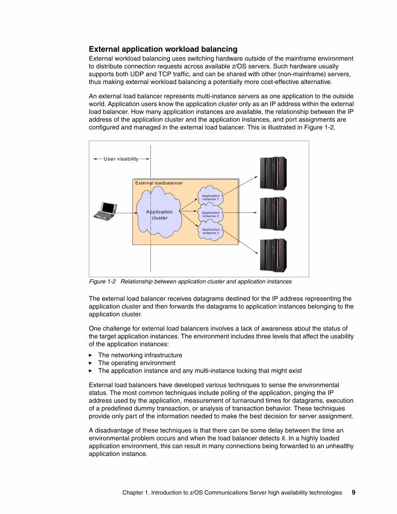
An external load balancer represents multi-instance servers as one application to the outside world. Application users know the application cluster only as an IP address within the external load balancer. How many application instances are available, the relationship between the IP address of the application cluster and the application instances, and port assignments are configured and managed in the external load balancer. This is illustrated in Figure 1-2.
Figure 1-2 Relationship between application cluster and application instances
The external load balancer receives datagrams destined for the IP address representing the application cluster and then forwards the datagrams to application instances belonging to the application cluster.
One challenge for external load balancers involves a lack of awareness about the status of the target application instances. The environment includes three levels that affect the usability of the application instances:
� The networking infrastructure� The operating environment� The application instance and any multi-instance locking that might exist
External load balancers have developed various techniques to sense the environmental status. The most common techniques include polling of the application, pinging the IP address used by the application, measurement of turnaround times for datagrams, execution of a predefined dummy transaction, or analysis of transaction behavior. These techniques provide only part of the information needed to make the best decision for server assignment.
A disadvantage of these techniques is that there can be some delay between the time an environmental problem occurs and when the load balancer detects it. In a highly loaded application environment, this can result in many connections being forwarded to an unhealthy application instance.
Applicationcluster
Application instance 1
Application instance 2
Application instance 3
User visability
External loadbalancer
Chapter 1. Introduction to z/OS Communications Server high availability technologies 9

The reverse problem arises when the application instance becomes fully operational again. Hybrid internal/external workload balancing approaches (discussed in “Hybrid internal/external approaches” on page 10) can give external load balancers (such as CSS) real-time awareness of the status of the sysplex environment and applications.
The strength of external load balancers is that they are dedicated devices performing a fixed set of tasks. They typically have significant processing capacity, giving them the ability to find and make decisions using higher-layer information buried deep inside datagrams rather than just using IP addresses, including application-specific information such as HTTP (or FTP) Uniform Resource Locators (URLs). External load balancers can also be implemented in redundant modes for availability, and more devices can usually be added in parallel to increase capacity. External load balancers are especially attractive (as compared to internal workload balancing) when the workload includes large amounts of inbound data traffic, because of their more-efficient inbound data path.
External application workload balancing is discussed in detail (including implementation examples) in Chapter 6, “External application workload balancing” on page 159.
Hybrid internal/external approachesIn many cases, your application load balancing requirements might be such that purely internal or external workload balancing will be satisfactory. However, in some situations you might need elements of both approaches.
For example, you might need the UDP workload balancing capability of an external load balancer but want to make z/OS application load balancing decisions based upon real-time awareness of current application workloads and performance. Two technology solutions address this requirement:
� Sysplex Distributor’s Multi-Node Load Balancing (MNLB) Service Manager support� z/OS Load Balancing Advisor (LBA) that uses the Server Application State Protocol
(SASP)
In the MNLB architecture, the entity that decides which target server is to receive a given connections is called the Service Manager. The entity that forwards data to target servers is called the Forwarding Agent. In a hybrid environment, the Sysplex Distributor acts as the Service Manager and switches perform the Forwarding Agent role.
Note that the Sysplex Distributor makes the actual workload distribution decision. Then, acting as a Service Manager, Sysplex Distributor relays that decision to the Forwarding Agents, which thereafter directly send traffic for that connection to the target server, bypassing the distribution stack (thereby saving the mainframe CPU cycles associated with routing messages through the distribution stack).
The z/OS LBA is a z/OS Communications Server component that allows any external load balancing solution to become sysplex-aware. The external load balancer must support the Server Application State Protocol (SASP) to obtain sysplex information through this function. Sysplex awareness information is collected by the LBA, a weight metric is calculated (based upon Workload Manager (WLM) and z/OS Communications Server information), and then the weight is sent to the external load balancer. Ultimately, however, the external load balancer
Note: Because Sysplex Distributor makes the actual workload distribution decision, we chose to include Sysplex Distributor’s MNLB Service Manager support (including implementation examples) in Chapter 5, “Internal application workload balancing” on page 95.
10 IBM z/OS V1R10 Communications Server TCP/IP Implementation Volume 3: High Availability, Scalability, and Performance

decides which application instance is best for the next request, which makes the LBA/SASP approach slightly different from the MNLB Service Manager approach.
Hybrid solutions, though more complex, combine the information advantages of internal workload balancing with the routing efficiency and functionality of external load balancing.
1.3 Quick start table
The information in Table 1-2 can help you quickly find your way to the parts of this book that are of interest to you. Start by finding the row in the table that most closely corresponds to your environment: single z/OS system or z/OS Parallel Sysplex, and with or without the use of dynamic routing in your z/OS environment. Then find the column with availability, scalability, or performance functionality that interests you. In the table cells, we have identified technologies that might be helpful for you and where they are discussed in the book.
Note: Because the external load balancer makes the actual workload distribution decision, we chose to include the detailed discussion of the LBA/SASP approach (including implementation examples) in Chapter 6, “External application workload balancing” on page 159.
Chapter 1. Introduction to z/OS Communications Server high availability technologies 11

Table 1-2 Quick start for high availability, scalability, and performance
High availability Scalability Performance
Network connectivity
Application Workload balancing
Single z/OS system without dynamic routing
Static VIPA and ARP takeover (Chapter 2, “Virtual IP addressing” on page 13, and Chapter 3, “VIPA without dynamic routing” on page 45)
� SHAREPORT and SHAREPORTWLM (Chapter 5, “Internal application workload balancing” on page 95)
� External WLB (Chapter 6, “External application workload balancing” on page 159)
� LBA/SASP (Chapter 6, “External application workload balancing” on page 159)
� General� TCP/IP� z/OS UNIX®� Storage� Applications
(Chapter 8, “Performance and tuning” on page 239)
Single z/OS system with dynamic routing
Static VIPA and OSPF (Chapter 2, “Virtual IP addressing” on page 13, and Chapter 4, “VIPA with dynamic routing” on page 65)
z/OS Parallel Sysplex without dynamic routing
Static VIPA and ARP takeover (Chapter 2, “Virtual IP addressing” on page 13, and Chapter 3, “VIPA without dynamic routing” on page 45)
DVIPA and ARP takeover (Chapter 2, “Virtual IP addressing” on page 13, and Chapter 3, “VIPA without dynamic routing” on page 45
� Distributed DVIPA and Sysplex Distributor (Chapter 2, “Virtual IP addressing” on page 13 and Chapter 6, “External application workload balancing” on page 159)
� External WLB (Chapter 6, “External application workload balancing” on page 159)
� LBA/SASP (Chapter 6, “External application workload balancing” on page 159)
z/OS Parallel Sysplex with dynamic routing
Static VIPA and OSPF (Chapter 2, “Virtual IP addressing” on page 13, and Chapter 4, “VIPA with dynamic routing” on page 65)
DVIPA and OSPF (Chapter 2, “Virtual IP addressing” on page 13, and Chapter 4, “VIPA with dynamic routing” on page 65)
12 IBM z/OS V1R10 Communications Server TCP/IP Implementation Volume 3: High Availability, Scalability, and Performance

Chapter 2. Virtual IP addressing
In TCP/IP networking, Internet Protocol (IP) addresses are typically assigned to physical network interfaces. If a server has two physical interfaces, a separate IP address is assigned to each of them.
IBM introduced the concept of Virtual IP Addressing (VIPA) for its z/OS environment to support the use of IP addresses, representing TCP/IP stacks, applications, or clusters of applications, that are not tied to any specific physical interface. The association between a VIPA and an actual physical interface is subsequently accomplished using either the Address Resolution Protocol (ARP) or dynamic routing protocols (such as OSPF).
This chapter discusses the following topics.
2
Section Topic
2.1, “Basic concepts of Virtual IP Addressing” on page 14
Basic concepts, commands, and functions associated with a VIPA
2.2, “Importance of VIPA” on page 26 Why VIPA is important
2.3, “Timing of DVIPA activation” on page 27 Controlling the timing of when a stack joins the TCP/IP sysplex group
2.4, “Dynamic VIPA example” on page 34 Implementation of a basic VIPA environment
© Copyright IBM Corp. 2009. All rights reserved. 13

2.1 Basic concepts of Virtual IP Addressing
The z/OS Communications Server supports two types of Virtual IP Addressing (VIPA):
� Static� Dynamic
A static VIPA is an IP address that is associated with a particular TCP/IP stack. Using either ARP takeover or a dynamic routing protocol (such as OSPF), static VIPAs can enable mainframe application communications to continue unaffected by network interface failures. As long as a single network interface is operational on a host, communication with applications on the host will persist. An example configuration for a static VIPA can be seen in Example 4-7 on page 77.
Static VIPAs have the following characteristics:
� They can be activated during TCP/IP initialization or VARY TCPIP, OBEYFILE command processing, and are configured using an appropriate set of DEVICE, LINK, HOME, and, optionally, OMPROUTE configuration statements or BSDROUTINGPARMS statements for IPv4 Static VIPAs (or INTERFACE statements for IPv6 Static VIPAs).
� Using the SOURCEVIPA configuration option, or SOURCEVIPA parameter on the INTERFACE configuration statement, static VIPAs can be used as the source IP address for outbound datagrams for TCP, RAW, UDP (except routing protocols), and ICMP requests.
� They can be specified as the source IP address for outbound TCP connection requests for all applications using this stack with TCPSTACKSOURCEVIPA, or just a specific job and a specific destination through the use of the SRCIP profile statement block.
� The number of static VIPAs on a stack is limited only by the range of host IP addresses that are available for that host.
� They can be moved to a backup stack after the original owning stack has left the XCF group (such as resulting from some sort of failure), by using VARY TCPIP,,OBEYFILE command processing to configure the VIPA on the backup stack.
Dynamic VIPAs (DVIPAs) can be defined on multiple stacks and moved from one TCP/IP stack in the sysplex to another automatically. One stack is defined as the primary or owning stack, and the others are defined as backup stacks. Only the primary stack is made known to the IP network.
TCP/IP stacks in a sysplex exchange information about DVIPAs, their existence, and their current location, and the stacks are continuously aware of whether the partner stacks are still functioning. If the owning stack leaves the XCF group (such as resulting from some sort of failure), then one of the backup stacks automatically takes its place and assumes ownership of the DVIPA. The network simply sees a change in the routing tables (or in the adapter that responds to ARP requests).
In this case, applications associated with these DVIPAs are active on the backup systems, thereby providing a hot standby and high availability for the services. DVIPA addresses identify applications independently of which images in the sysplex the server applications execute on and allow an application to retain its identity when moved between images in a sysplex.
Note: Static VIPA does not require sysplex (XCF communications) because it does not require coordination between TCP/IP stacks.
14 IBM z/OS V1R10 Communications Server TCP/IP Implementation Volume 3: High Availability, Scalability, and Performance

DVIPAs can be moved among any TCP/IP stack in the sysplex (that is configured to allow it) through any of the following mechanisms:
� Automatically, for example, in response to the owning stack leaving the XCF group (such as resulting from some sort of failure)
� Through an application program (using an IOCTL macro), when one instance of an application takes over primary function from another
� By using a utility program (MODDVIPA) from the operator console
Figure 2-1 shows a simple example of DVIPA that illustrates a case where a TCP/IP stack (and associated applications) has failed.
Figure 2-1 DVIPA address movement
DVIPA automatically moves operation of the failed IP address to another z/OS image. With proper planning, the same application is available on the second z/OS image and it immediately picks up the workload that is directed to the IP address. External users see only workload directed to an IP address; the shift of this IP address from the first z/OS to the second z/OS is largely transparent.
Dynamic VIPAs are defined using the VIPADynamic statement (as shown in Figure 2-2 on page 16) and have the following characteristics:
� They can be configured to be moved dynamically from a failing stack to a backup stack within the same sysplex without operator intervention or external automation. This is a stack-managed configuration and is defined using the VIPADefine and VIPABackup parameters.
� They can be activated dynamically by an application program (using IOCTL) or by a supplied utility (MODDVIPA). This is event activation or command activation and is managed using the VIPARange parameter.
� They can be specified on a TCPSTACKSOURCEVIPA statement. This allows a user to specify one Dynamic VIPA to be used as the source IP address for outbound datagrams for TCP-only requests.
XCF Communication
IP Network
z/OS TCP/IP Stack
z/OS TCP/IP Stack
DVIPA DVIPA(backup)
Chapter 2. Virtual IP addressing 15

When used with Sysplex Distributor, DVIPAs (in such cases referred to as distributed DVIPAs) allow a cluster of hosts, running the same application service, to be perceived as a single large server node. Distributed DVIPAs are defined using the VIPADistribute parameter with the VIPADynamic statement (as shown in Figure 2-2) and have the following characteristics:
� They have all the characteristics of DVIPAs, but cannot be dynamically activated by an application program.
� One stack (called the routing stack) defines a DVIPA and advertises its existence to the network. Stacks in the target distribution list activate the DVIPA and accept connection requests.
� Connection workload can be spread across several stacks.
Figure 2-2 DVIPA configuration
Refer to “Distributed DVIPA (Sysplex Distributor)” on page 20 for a more detailed description of this function.
2.1.1 Application availability modes
Consider the following availability modes for an application (arranged in order from least available to most highly available):
� Single-instance
Running just one instance of an application
� Single-instance with automated restart
Running just one instance of an application, but leveraging automation utilities such as Automatic Restart Manager (ARM) in the case of an application failure to either immediately restart the application in the same place or start it on another stack
� Single-instance with hot standby
Running just one instance of an application, but having standby instances of the same application running and ready to take over in the event of a failure (or termination) of the first instance (this is still essentially single-instance because there is only one copy of the application that is available at any given time)
� Multiple-instance
By actually running multiple, concurrently available instances of the same application (and balancing workload across them)
Multiple application instances will provide the highest availability (as well as higher scalability), but not all applications can support multiple concurrent instances; for example:
� An FTP server might require exclusive access to certain data sets.
� A TN3270 server might require use of specific LU names.
� Software license limitations.
VIPADynamic ENDVIPADynamic
VIPABackup
VIPADEFine
VIPADELete
VIPARange
VIPADISTribute
16 IBM z/OS V1R10 Communications Server TCP/IP Implementation Volume 3: High Availability, Scalability, and Performance

� Application implementation specific requirements that limit the application to a single instance, such as lack of locking or data sharing in the basic program design, need for exclusive access to certain resources, architecturally-related dependencies, or other issues
� Possible client dependencies upon a particular server instance
For the purposes of this chapter we assume that such single-instance characteristics are fixed and cannot be changed. Depending upon your applications, therefore, you might need to implement several of these application availability modes.
2.1.2 DVIPA and distributed DVIPA
Ultimately, the availability modes that you need to support (based upon your specific set of applications) will dictate how you set up and use DVIPAs and distributed DVIPAs. Table 2-1 on page 17 summarizes the choices for providing availability that is higher than just running a single instance of an application.
Table 2-1 Matching DVIPA support with application requirements
DVIPAs can be moved between TCP/IP stacks by any of the following methods:
� Automatic movement of a VIPA from a failing TCP/IP stack to a backup stack, known as automatic takeover and takeback
� Dynamic allocation of a VIPA by an application program application programming interface (API) call, using any of these methods:
– The application issues a bind() to that particular (specific) IP address.
– The application binds to INADDR_ANY instead of a specific IP address, but the server bind control function changes the generic bind() to a specific one.
– An authorized application issues a SIOCSVIPA IOCTL command. An example of such an application is the MODDVIPA utility.
� Manual movement of a VIPA by deactivating or reactivating it with the VARY TCPIP,,SYSPLEX command
Availability mode Type of DVIPA to use How to define it
Single-instance with automated restart (same stack or different stack)
Event-activated DVIPA (driven by application bind, IOCTL, or MODDVIPA command)
VIPARANGE
Single-instance with hot standby
Stack-managed DVIPA VIPADEFINE (primary owner), VIPABACKUP (backup stacks)
Multiple-instance Distributed DVIPA VIPADEFINE (primary owner) VIPABACKUP (backup stacks)VIPADISTRIBUTE
Chapter 2. Virtual IP addressing 17

Event-activated DVIPAsEvent-activated DVIPA functions are indicated by the VIPARANGE parameter in the TCP/IP profile. Activation of an application-specific DVIPA IP address associated with a specific application instance occurs only using an application program’s API call, in any of the following ways:
� When the application instance issues a bind() function call and specifies an IP address that is not active on the stack. The stack will activate the address as a DVIPA, if it meets certain criteria. When the application instance closes the socket, the DVIPA is deleted.
� Some applications cannot be configured to issue bind() for a specific IP address, but are unique application-instances. For such applications, a utility is provided (MODDVIPA), which issues SIOCSVIPA or SIOCSVIPA6 ioctl() to activate or deactivate the DVIPA.
This utility can be included in a JCL procedure or OMVS script to activate the DVIPA before initiating the application. As long as the same JCL package or script is used to restart the application instance on another LPAR in the event of a failure, the same DVIPA will be activated on the new stack.
� An alternative for unique application-instance applications that do not contain the logic to bind to a unique IP address is to use the BIND parameter on the PORT reservation statement. It is usually a good practice to reserve a port for the listening socket of a server application.
If the BIND parameter and an IP address are specified on the PORT reservation statement for a server application, and the application binds a socket to that port and specifies INADDR_ANY, then z/OS TCP/IP converts the bind to be specific to the IP address specified on the PORT reservation statement.
From that point on, it appears as though the application itself had issued the bind() specifying the designated IP address, including having the IP address deleted when the server application closes the socket.
Because the VIPA is specified by the application, it does not need to be uniquely defined in the TCP/IP profile. However, we must ensure that the addresses being used by the application correspond to our IP addressing scheme. We use the VIPARange statement in the TCP/IP profile to indicate the range of VIPAs that we are willing to activate dynamically, as shown in Figure 2-3.
Figure 2-3 Definition format for VIPARange
The VIPARange statement defines an IP subnetwork using a network address (prefix) and a subnet mask. Because the same VIPA address cannot be activated by IOCTL or bind() while also participating in automatic takeover as defined by VIPADEFine/VIPABackup, we recommend that subnets for VIPADEFine be different from subnets for VIPARange.
VIPARange in itself does not create, activate, or reserve any dynamic VIPAs. It merely defines an allocated range within which program action (or the BIND parameter or a PORT statement) can cause a dynamic VIPA to be created and activated for a specific IP address. The same range can have DVIPAs defined through VIPADEFINE or VIPABACKUP, provided that no attempt is made to use the same IP address for both VIPADEFINE and activation uses the BIND program.
VIPARange address_mask ipaddrDEFINE
DELEte
MOVEable NONDISRUPTive
MOVEable DISRUPTive
18 IBM z/OS V1R10 Communications Server TCP/IP Implementation Volume 3: High Availability, Scalability, and Performance
For our operation, we used the following definition:
VIPADYNAMIC VIPARANGE DEFINE MOVEABLE NONDISRUPT 255.255.255.0 10.30.30.1 ENDVIPADYNAMIC
After it is activated on a stack using bind() or IOCTL, a Dynamic VIPA IP address remains active until the VIPA IP address is moved to another stack or is deleted. The system operator might delete an active application-specific Dynamic VIPA IP address by using the MODDVIPA utility or by stopping the application that issued the bind() to activate the VIPA. To remove an active VIPARange statement, the VIPARange DELETE statement can be used.
Deleting a VIPARANGE does not affect existing DVIPAs that are already activated within the range, but it does prevent new ones from being activated within the deleted range until the VIPARANGE is reinstated.
Stack-managed DVIPAsStack-managed DVIPAs are defined by VIPADefine and VIPABackup, and are moved between stacks. The switch can be automatic or manual, as explained here.
� Automatic
If the owning stack leaves the XCF group (for example, resulting from some sort of failure), the stack with an already-configured VIPABACKUP definition for that DVIPA activates and advertises the DVIPA, and this is the TAKEOVER operation. Multiple stacks can back up a DVIPA. The stack with the highest configured rank will take over.
� Manual (planned)
This method uses VARY TCPIP,,SYSPLEX deact/act operator commands.
A deactivate command:
– If the DVIPA is active, deactivate deletes the DVIPA allowing a backup stack to take over the DVIPA.
– If the DVIPA is a backup, deactivate removes this stack as a backup, preventing this stack from taking over if the current owner leaves the XCF group (for example, resulting from some sort of failure).
A reactivate command:
– Causes takeback for a VIPADEFINE DVIPA.
– Re-enables VIPABACKUP DVIPA to perform takeover if a stack leaves the XCF group.
Applications that bind() to INADDR_ANYAn application can issue a bind() to INADDR_ANY to accept connection requests from any IP address associated with the stack. This is insufficient if the application must be associated with a specific VIPA address. There are three ways to manage this situation:
� Cause the application to bind() to a specific address (instead of INADDR_ANY) by using the Server Bind Control function that is implemented by the BIND keyword on a PORT statement.
� Modify the application to bind() to a specific address.
� Use the utility MODDVIPA or modify the application to send the appropriate IOCTL.
The most attractive solution is to use the Server Bind Control function because it does not require changing the application. Using this function, a generic server (such as the TN3270 server) can be directed to bind to a specific address instead of INADDR_ANY. When the application attempts binds to INADDR_ANY, the bind() is intercepted and converted to the
Chapter 2. Virtual IP addressing 19

specified IP address. The process then continues as though the server had issued a bind() to that specific address. In order to use this function, however, the port used by the application must be known in advance so that it can be added to the PORT statement in the TCP/IP profile.
In situations where the application cannot take advantage of the server bind control function and cannot be otherwise modified, the MODDVIPA utility can be used to create a Dynamic VIPA IP address using the IOCTL call. The utility can be initiated through JCL, from the OMVS command line, or from a shell script. This utility is in EZB.MODDVIPA.sysname.tcpname. For more detailed information about the MODDVIPA utility, refer to z/OS CS: IP Configuration Guide, SC31-8775.
In most of our examples, we active the DVIPA address by the BIND keyword on the PORT statement.
Using the MODDVIPA utilityWe used the following procedure to run the MODDVIPA utility:
//TCPDVP PROC //TCPDVP EXEC PGM=MODDVIPA,REGION=0K,TIME=1440, // PARM='-p TCPIPC -c 10.30.30.1' 1 //SYSPRINT DD SYSOUT=A,DCB=(RECFM=FB,LRECL=132,BLKSIZE=132)//SYSERR DD SYSOUT=A //SYSERROR DD SYSOUT=A //SYSDEBUG DD SYSOUT=A //SYSUDUMP DD SYSOUT=A //SYSABEND DD SYSOUT=A
The utility expects a parameter specifying the VIPA address to be activated. It can also be used to delete a VIPA address as an alternative to using a VARY OBEY operator command. The parameter option field can be -c for create or -d for delete. This example creates a Dynamic VIPA 1 with IP address 10.30.30.1.
Activation of the Dynamic VIPA IP address will succeed as long as the desired IP address is not claimed by any other stack, is not an IP address of a physical interface or a static VIPA, and is not defined using VIPADEFine or VIPABackup in a VIPADynamic block.
MODDVIPA must run with APF authorization. For additional information about APF authorization, refer to IBM z/OS V1R10 Communications Server TCP/IP Implementation Volume 4: Security and Policy-Based Networking, SG24-7699.
Distributed DVIPA (Sysplex Distributor)Sysplex Distributor is a function that allows an IP workload to be distributed to multiple server instances within the sysplex without requiring changes to clients or networking hardware and without delays in connection setup. It allows you to implement a dynamic VIPA as a single network-visible IP address that is used for a set of hosts belonging to the same sysplex cluster. A client on the IP network sees the sysplex cluster as one IP address, regardless of the number of hosts in the cluster.
With Sysplex Distributor, clients receive the benefits of workload distribution provided by both the Workload Manager (WLM) and the Quality of Service (QoS) Policy Agent. In addition, Sysplex Distributor ensures high availability of the IP applications running on the sysplex cluster by providing continued operation if a LAN fails, or an entire IP stack leaves the XCF group=, or a z/OS image is lost.
20 IBM z/OS V1R10 Communications Server TCP/IP Implementation Volume 3: High Availability, Scalability, and Performance

Sysplex Distributor operationConsider the environment shown in Figure 2-4. It includes four TCP/IP stacks (in four z/OS images) running in the same sysplex cluster in WLM GOAL. All stacks have SYSPLEXROUTING, DATAGRAMFWD, and DYNAMICXCF configured. Assume that:
� H1 is configured as the distributing IP stack with V1 as the Dynamic VIPA (DVIPA) assigned to the sysplex cluster.
� H2 is configured as backup for V1.
� H3 and H4 are configured as secondary backups for V1.
� APPL1 is running in all the hosts that are members of the same sysplex cluster.
Figure 2-4 Sysplex Distributor functionality
Sysplex Distributor works as follows:
1. When IP stack H1 is activated, the definitions for the local XCF1 link are created dynamically due to DYNAMICXCF being coded in the H1 profile. Through this link, H1 recognizes the other IP stacks that belong to the same sysplex cluster and their XCF associated links: XCF2, XCF3, and XCF4.
2. The DVIPA assigned to the sysplex cluster and the application ports that this DVIPA serves are read from the VIPADISTRIBUTE statement in the profile data set. An entry in the home list for all stacks is added for the distributed IP address. The home list entry on the target stacks is done with a message that H1 sends to all the stacks read from the VIPADISTRIBUTE statement. Only one stack (H1, in this example) advertises the DVIPA through the RIP or OSPF routing protocol.
Important: Note that Sysplex Distributor only works for TCP applications, not UDP applications.
WLM/QOS
Dest=V1Src=a.b.c.d
Unadvertised V1
Unadvertised V1XCF2
XCF3
XCF4XCF1
DVIPA: V1 H1 APPL1
H3 APPL1
H2 APPL1
CRT
DPT: Destination port tableCRT: Connection routing table
SYN? Select server Add conn to tableRST/FIN? Find conn table Remove tableOtherwise? Find conn tableForward to server (x)
DPT CRT
CRT
CF
Dest=V1Src=a.b.c.d
Unadvertised V1
H4 APPL1
CRT
Chapter 2. Virtual IP addressing 21
3. H1 monitors whether there is at least one application (APPL1 in Figure 2-4) with a listening socket for the designated port and DVIPA. H2, H3, and H4 send a message to H1 when a server (APPL1) is bound to either INADDR_ANY or specifically to the DVIPA (and, of course, the designated port). With that information, H1 builds a table with the name of the application and the IP stacks that could serve a connection request for it. The table matches the application server listening port with the target XCF IP address.
4. When a network client requests a service from APPL1, DNS resolves the IP address for the application with the DVIPA address. (This DNS could be any DNS in the IP network and does not need to register with WLM.)
5. When H1 receives the connection request (a TCP segment with the SYN flag), it queries WLM or QoS (or both) to select the best target stack for APPL1 and forwards the SYN segment to the chosen target stack. In our example, it is APPL1 in H4 that best fits the request.
6. An entry is created in the connection routing table (CRT) in H1 for this new connection, with XCF4 as the target IP address. H4 also adds the connection to its connection routing table.
If a program binds to DVIPA on H4 and initiates a connection, H4 needs to send a message to H1 so that H1 can update its connection routing table accordingly. As an example, this is used when the FTP server on H4 would initiate a data connection (port 20) to a client.
7. The H1 IP stack forwards subsequent incoming data for this connection to the correct target stack.
8. When the H4 IP stack decides that the connection no longer exists, it informs the H1 IP stack with a message so H1 can remove the connection from its connection routing table.
Backup capabilityThe VIPA takeover functionality supports Sysplex Distributor. The following example illustrates its usage, as depicted in Figure 2-5 on page 23.
Consider the situation where our example has been running for some time without problems. APPL1 connections have been distributed (according to WLM directions) to H1, H2, H3, and H4. Many connections are currently established between several APPL1 server images and clients in the IP network.
Assume we now have a major failure in our distributing IP stack (H1). Automatic dynamic VIPA takeover occurs. This function allows a VIPA address to automatically move from one IP stack where it was defined to another one in the event of the failure of the first. The VIPA address remains active in the IP network, allowing clients to access the services associated with it.
22 IBM z/OS V1R10 Communications Server TCP/IP Implementation Volume 3: High Availability, Scalability, and Performance

Figure 2-5 DVIPA backup capability
In our example, H1 is the distributing IP stack and H2 is the primary VIPABACKUP IP stack. When H1 fails, the following occurs:
1. All the IP connections terminating at H1 are lost. The Sysplex Distributor connection routing table (CRT) is also lost.
2. H2 detects that H1 is down (because it has left the XCF group) and defines itself as the distributing IP stack for the VIPA.
3. Because H2 saved information about H1, it informs the other target stacks that it knows V1 is distributable.
4. H3 and H4 are informed that H2 is the chosen backup for V1 and they immediately send connection information regarding V1 to IP stack H2.
5. H2 advertises V1 (DVIPA) through the dynamic routing protocol (RIP or OSPF). Retransmitted TCP segments for already existing connections or SYN segments for new connections are hereafter processed by IP stack H2 and routed by H2 to the appropriate target stacks.
Notice that only the IP connections with the failing IP stack are lost. All other connections remain allocated and function properly.
RecoveryAfter the H1 IP stack is activated again, the process of taking back V1 to H1 is started automatically. This process is nondisruptive for the IP connections already established with V1, regardless of which host is the owner at that time (in our example, H2). In our example, connection information is maintained by H2. When H1 is reactivated, H2 sends its connection information to H1. This gives H1 the information it needs to distribute packets again for existing connections to the correct stacks in the sysplex.
Dest=V1Src=a.b.c.d
Unadvertised V1
XCF2XCF3
XCF4XCF1
DVIPA: V1 H1 APPL1
H3 APPL1
H2 APPL1Same algorithm as inoriginal distributor Dest=V1
Src=a.b.c.d
W LM/QOS
V1TakeOver
DPT CRT
CRT
SYN ? Select server Add conn to tableRST/FIN ? F ind conn table Rem ove tableOtherwise ? F ind conn tableForward to server (x)
DPT CRTDPT: Destination port tableCRT: Connection routing table
CF
Unadvertised V1
H4 APPL1
CRT
Chapter 2. Virtual IP addressing 23

Connections with the backup host are not broken when the V1 address is taken back to H1, and takeback is not delayed until all connections with the backup host have terminated. Figure 2-6 illustrates this situation.
Figure 2-6 Sysplex Distributor and VIPA takeback
Dynamic routing with Sysplex DistributorRouting IP packets for Sysplex Distributor can be divided into two cases:
� Routing inside the sysplex cluster� Routing through the IP network
Routing inside the sysplex cluster is accomplished by the distributing host. All incoming traffic (new connection requests and connection data) arrives at the distributing stack. This stack forwards the traffic to the target applications in the sysplex cluster, using XCF links or using the VIPARoute function. (See 2.1.3, “VIPARoute function” on page 25 for more information.) OSA-Express connections can be used, as well.
Routing outside the sysplex is done by the downstream routers. Those routers learn about the DVIPA assigned to the sysplex dynamically using OSPF or RIP routing protocols. It is usually necessary to implement either one of these routing protocols in all the IP stacks of the sysplex cluster.
The distributing VIPA address is dynamically added to the home list of each IP stack participating in the Sysplex Distributor, but only one IP stack advertises the sysplex VIPA address to the routers: the one defined as the distributing IP stack. The other stacks do not advertise it and only the backup IP stack will do so if the distributing IP stack leaves the XCF group (for example, resulting from some sort of failure).
WLM/QOS
Dest=V1Src=a.b.c.d
Dest=V1Src=a.b.c.d
Unadvertised V1
Unadvertised V1XCF2
XCF3
XCF4XCF1
DVIPA: V1 H1 APPL1
H3 APPL1
H2 APPL1
V1TakeBack
OriginalDistributor algorithm moves back
DPT CRT
CRT
DPT CRT
DPT: Destination port tableCRT: Connection routing table
CF
Unadvertised V1
H4 APPL1
CRT
24 IBM z/OS V1R10 Communications Server TCP/IP Implementation Volume 3: High Availability, Scalability, and Performance

When using OMPROUTE, consider the following:
� Names of Dynamic VIPA interfaces are assigned dynamically by the stack when they are created. Therefore, the name coded for the OSPF_Interface statement in the Name field is ignored by OMPROUTE.
� We recommend that each OMPROUTE server have an OSPF_Interface defined for each Dynamic VIPA address that the IP stack might own or, if the number of DVIPAs addresses is large, a wildcard should be used.
It is also possible to define ranges of dynamic VIPA interfaces using the subnet mask and the IP address on the OSPF_Interface statement. The range defined includes all the IP addresses that fall within the subnet defined by the mask and the IP address. The following example defines a range of Dynamic VIPA addresses from 10.30.10.1 to 10.30.10.254:
OSPF_Interface IP_address = 10.30.10.1 Name = dummy_name Subnet_mask = 255.255.255.0
For consistency with the VIPARANGE statement in the TCPIP.PROFILE, any value that can fall within this range can be used to define a range of dynamic VIPAs.
2.1.3 VIPARoute function
The VIPARoute function was introduced with the z/OS V1R7 Communications Server. Previously, all DVIPA IP traffic was forwarded to target stacks only by using Dynamic XCF interfaces. The VIPARoute function can use any available interface for this traffic forwarding. Using alternative interfaces can improve performance while reducing the utilization of Sysplex XCF interfaces.
Figure 2-7 illustrates this function where a mixture of XCF, an external Ethernet LAN, and HiperSockets could be used to forward traffic. WLM and QoS weights are factors considered in target selection for new requests. However, outgoing traffic generated by the applications is routed according to the routing table in each stack.
Figure 2-7 VIPARoute function
HiperSockets
LPAR A LPAR B LPAR D LPAR E
OSA-EOSA-E
10.20.20.1
LPAR C
CF
XCF connectivity
VIPARoute definition links
10.20.20.1 10.20.20.1
HiperSockets
Chapter 2. Virtual IP addressing 25
A VIPAROUTE statement (in the TCP/IP PROFILE) defines a route from a distributing stack or a backup distributing stack to a target stack. For example:
VIPAROUTE DEFINE 10.1.1.5 10.50.10.1
This statement says that traffic (within the sysplex) from 10.1.1.5 to 10.50.10.1 should be handled by the VIPAROUTE function, which selects the most appropriate route at that instant. You can use the command NETSTAT VIPADYN /-v to query the status of a dynamic VIPA, including the usage of VIPAROUTE; for example:
MVS TCP/IP NETSTAT CS V1R9 TCPIP Name: TCPIPC 11:24:56Dynamic VIPA:IpAddr/PrefixLen: 10.20.20.1/28Status: Active Origin: VIPADefine DistStat: Dist/DestVIPA Route:DestXCF: 10.1.1.5TargetIp: 10.50.10.1RtStatus: Active
Note that z/OS releases prior to V1R7 cannot process a VIPAROUTE statement and will send distributed traffic using Dynamic XCF interfaces.
2.2 Importance of VIPA
VIPA provides a foundation technology solution for enhancing the availability and scalability of a z/OS system by providing the following capabilities:
� Automatic and transparent recovery from device and adapter failures.
When a device (for example, a channel-attached router) or an adapter (for example, an OSA-Express adapter) fails, then another device or link can automatically provide alternate paths to the destination.
� Recovery when a z/OS TCP/IP stack leaves the XCF group (for example, resulting from some sort of failure), where an alternate z/OS TCP/IP stack has the necessary redundancy.
Assuming that an alternate stack is installed to serve as a backup, the use of VIPAs enables the backup stack to activate the VIPA address of the failed stack. Connections on the failed primary stack will be disrupted, but they can be reestablished on the backup using the same IP address as the destination. In addition, the temporarily reassigned VIPA address can be restored to the primary stack after the cause of failure has been removed.
� Limited scope of a stack or application failure.
If a DVIPA is distributed among several stacks, the failure of only one stack affects only the subset of clients connected to that stack. If the distributing stack experiences the failure, a backup assumes control of the distribution and maintains all existing connections.
� Enhanced workload management through distribution of connection requests.
With a single DVIPA being serviced by multiple stacks, connection requests and associated workloads can be spread across multiple z/OS images according to Workload Manager (WLM) and Service Level Agreement policies (for example, QOS).
� Allows the nondisruptive movement of an application server to another stack so that workload can be drained from a system in preparation for a planned outage.
26 IBM z/OS V1R10 Communications Server TCP/IP Implementation Volume 3: High Availability, Scalability, and Performance

2.3 Timing of DVIPA activation
By default, as soon as TCP/IP stack starts and the basic stack function’s initialization completes, the stack joins the TCP/IP sysplex group and processes its dynamic VIPA configuration within TCP/IP profile statements. It is possible to control the timing of when a stack joins the TCP/IP sysplex group and activates dynamic VIPAs either by TCP/IP profile definitions or by Vary TCPIP operator commands.
Figure 2-8 illustrates a timeline showing the process of sysplex-related definitions and autologged server binding to a dynamic VIPA when TCP/IP stack starts. The first row shows default processing without DELAYJOIN and DELAYSTART parameters. The second row shows the process with DELAYJOIN. The third row shows the one with both DELAYJOIN and DELAYSTART.
Figure 2-8 Startup sequence of TCP/IP stack
2.3.1 DVIPA definitions
z/OS Communications Server provides two options to control the timing of processing DVIPA-related definitions within the TCP/IP profile statements:
� DELAYJOIN (parameter on GLOBAL statement)� DELAYSTART (parameter on AUTOLOG statement)
DELAYJOIN DELAYJOIN specifies that joining the sysplex group and creating dynamic VIPAs is to be delayed until OMPROUTE is active.
When DELAYJOIN is specified, TCP/IP will not join the sysplex group until OMPROUTE is active. Because the stack’s dynamic VIPA configuration is not processed until after the stack has joined the sysplex group, this delay in joining the sysplex group ensures that OMPROUTE will be active and ready to advertise dynamic VIPAs when they are created on this stack.
Using AUTOLOG with DELAYJOINProcedures specified in the AUTOLOG statement automatically start as soon as TCP/IP initialization is completed.
Stack address Sysplex group and takes back
DVIPAs
Autologgedserver
binds to DVIPA
DVIPAs are unavailable
Stack addressspace start
with DELAYJOIN
OMPROUTE comes up and
begins advertising DVIPA
Autologgedserver
binds to DVIPA
Stack addressspace start
With DELAYJOIN& DELAYSTART
Bind to DVIPAs fail
space start
OMPROUTEcomes up and
begins advertisingDVIPA
Autologged server
binds to DVIPA
group Stack joins
Sysplex groupand takes back
DVIPAs
OMPROUTEcomes up and
begins advertisingDVIPA
Autologged server
binds to DVIPA
Stack joinssysplex group
and takes backDVIPAs
Stack joinssysplex group
and takes backDVIPAs
OMPROUTEcomes up and
begins advertisingDVIPA
Autologged server
binds to DVIPA
Chapter 2. Virtual IP addressing 27

If DELAYJOIN is configured, TCP/IP will not join the sysplex group and create dynamic VIPAs until OMPROUTE is ready to advertise them. However, procedures specified in the AUTOLOG statement can be started before OMPROUTE is active. Binds to dynamic VIPAs will fail until OMPROUTE is initialized and the stack has joined the sysplex group and created the dynamic VIPAs.
When the TCP/IP stack is started with DELAYJOIN configured, the following steps occur:
1. The stack completes basic initialization, but it is not in the sysplex group yet.
2. At that point, AUTOLOG will start the specified procedures.
3. When OMPROUTE has completed its initialization and is active, it notifies the stack.
4. The stack will join the sysplex group and process its dynamic configuration, which includes creating its dynamic VIPAs.
Until the stack has completed its dynamic configuration processing, any bind request to a dynamic VIPA will fail due to the delay in creating these DVIPAs.
DELAYSTARTz/OS Communications Server provides an optional keyword, DELAYSTART, for procedures specified on the AUTOLOG profile statement. DELAYSTART is used to identify procedures that should not be automatically started until after the stack has joined the sysplex group and its dynamic sysplex configuration is completed. After that occurs, bind requests to dynamic VIPAs can follow.
Example 2-1 shows the AUTOLOG statement specified with DELAYSTART for the procedure name FTPDC in the TCP/IP profile.
Example 2-1 Sample AUTOLOG definition
AUTOLOG 5 FTPDC JOBNAME FTPDC1 DELAYSTART ; FTP server OMPC ; OMPROUTE Server ENDAUTOLOG
You can use the NETSTAT CONFIG /-f command to display DELAYJOIN and DELAYSTART definitions, as illustrated in Example 2-2.
Example 2-2 Nestat Config/-f result
GLOBAL CONFIGURATION INFORMATION: TCPIPSTATS: NO ECSALIMIT: 0000000K POOLLIMIT: 0000000K MLSCHKTERM: NO XCFGRPID: IQDVLANID: 0 SEGOFFLOAD: NO SYSPLEXWLMPOLL: 060 EXPLICITBINDPORTRANGE: 00000-00000 SYSPLEX MONITOR: TIMERSECS: 0060 RECOVERY: NO DELAYJOIN: YES AUTOREJOIN: NO MONINTF: NO DYNROUTE: NO ZIIP:
Important: Do not specify the DELAYSTART parameter for your OMPFine ROUTE procedure if you specify the DELAYJOIN parameter on the GLOBALCONFIG profile statement. Otherwise, the stack will complete its basic initialization, but OMPROUTE will never be started because AUTOLOG is waiting for the stack to join the sysplex group. And the stack will not join the group and create its dynamic VIPAs because the stack is waiting for OMPROUTE to be active.
28 IBM z/OS V1R10 Communications Server TCP/IP Implementation Volume 3: High Availability, Scalability, and Performance

IPSECURITY:NO NETWORK MONITOR CONFIGURATION INFORMATION: PKTTRCSRV: NO TCPCNNSRV: NO SMFSRV: NO AUTOLOG CONFIGURATION INFORMATION: WAIT TIME: 0300 PROCNAME: FTPDC JOBNAME: FTPDC1 DELAYSTART: YES PARMSTRING: PROCNAME: OMPC JOBNAME: OMPC DELAYSTART: NO PARMSTRING: END OF THE REPORT
We used the FTP server FTPDC in the AUTOLOG statement as shown in Example 2-1 on page 28 and added a bind to the DVIPA in the PORT statement as follows:
PORT 20 TCP OMVS NOAUTOLOG ; FTP Server 21 TCP OMVS BIND 10.1.8.30; control port
Syslog messages will help you understand how the DELAYJOIN and DELAYSTART options work. Example 2-3 shows the startup of TCPIPC with DELAYJOIN:NO and DELAYSTART:NO, which is the default.
Example 2-3 Syslog - DELAYJOIN:NO and DELAYSTART:NO
16:11:20.27 -S TCPIPC,PROFILE=PROFC32A16:11:20.49 STC01790 EZZ7450I FFST SUBSYSTEM IS NOT INSTALLED16:11:22.67 STC01790 EZZ0300I OPENED PROFILE FILE DD:PROFILE16:11:22.67 STC01790 EZZ0309I PROFILE PROCESSING BEGINNING FOR DD:PROFILE16:11:22.67 STC01790 EZZ0316I PROFILE PROCESSING COMPLETE FOR FILE DD:PROFILE16:11:22.68 STC01790 EZZ0641I IP FORWARDING NOFWDMULTIPATH SUPPORT IS ENABLED16:11:22.69 STC01790 EZZ0350I SYSPLEX ROUTING SUPPORT IS ENABLED16:11:22.69 STC01790 EZZ0624I DYNAMIC XCF DEFINITIONS ARE ENABLED16:11:22.69 STC01790 EZZ0338I TCP PORTS 1 THRU 1023 ARE RESERVED16:11:22.69 STC01790 EZZ0338I UDP PORTS 1 THRU 1023 ARE RESERVED16:11:22.69 STC01790 EZZ0613I TCPIPSTATISTICS IS DISABLED16:11:22.69 STC01790 EZZ4202I Z/OS UNIX - TCP/IP CONNECTION ESTABLISHED FOR TCPIPC16:11:22.81 STC01790 EZB6473I TCP/IP STACK FUNCTIONS INITIALIZATION COMPLETE.16:11:22.81 STC01790 EZAIN11I ALL TCPIP SERVICES FOR PROC TCPIPC ARE AVAILABLE.16:11:24.71 STC01790 EZD1176I TCPIPC HAS SUCCESSFULLY JOINED THE TCP/IP SYSPLEX GROUP EZBTCPCS16:11:32.60 STC01790 S FTPDC16:11:32.60 STC01790 S OMPC
Example 2-4 shows the startup of TCPIPC with DELAYJOIN:YES and DELAYSTART:NO.
Example 2-4 Syslog - DELAYJOIN:YES and DELAYSTART:NO
16:20:58.77 -S TCPIPC,PROFILE=PROFC32A16:20:59.05 STC01804 EZZ7450I FFST SUBSYSTEM IS NOT INSTALLED16:21:01.48 STC01804 EZZ0300I OPENED PROFILE FILE DD:PROFILE16:21:01.48 STC01804 EZZ0309I PROFILE PROCESSING BEGINNING FOR DD:PROFILE16:21:01.49 STC01804 EZZ0316I PROFILE PROCESSING COMPLETE FOR FILE DD:PROFILE16:21:01.49 STC01804 *EZD1166E TCPIPC DELAYING SYSPLEX PROFILE PROCESSING - OMPROUTE IS NOT ACTIVE16:21:01.49 STC01804 EZZ0641I IP FORWARDING NOFWDMULTIPATH SUPPORT IS ENABLED16:21:01.49 STC01804 EZZ0350I SYSPLEX ROUTING SUPPORT IS ENABLED16:21:01.49 STC01804 EZZ0624I DYNAMIC XCF DEFINITIONS ARE ENABLED
Chapter 2. Virtual IP addressing 29

16:21:01.49 STC01804 EZZ0338I TCP PORTS 1 THRU 1023 ARE RESERVED16:21:01.49 STC01804 EZZ0338I UDP PORTS 1 THRU 1023 ARE RESERVED16:21:01.49 STC01804 EZZ0613I TCPIPSTATISTICS IS DISABLED16:21:01.49 STC01804 EZZ4202I Z/OS UNIX - TCP/IP CONNECTION ESTABLISHED FOR TCPIPC16:21:01.61 STC01804 EZB6473I TCP/IP STACK FUNCTIONS INITIALIZATION COMPLETE.16:21:01.61 STC01804 EZAIN11I ALL TCPIP SERVICES FOR PROC TCPIPC ARE AVAILABLE.16:21:11.52 STC01804 S FTPDC 16:21:11.52 STC01804 S OMPC 16:21:11.61 STC01805 IEF695I START OMPC WITH JOB OMPC IS ASSIGNED TO USER TCPIP,GROUP TCPGRP 16:21:11.62 STC01806 IEF695I START FTPDC WITH JOB FTPDC IS ASSIGNED TO USER TCPIP, GROUP TCPGRP : 16:21:11.86 STC01787 BPXF024I (TCPIP) Sep 11 16:21:11 ftpd›196653: EZYFT13E bind error : 048 EDC8116I Address not available. (errno2=0x744C7230) 16:21:11.86 STC01787 BPXF024I (TCPIP) Sep 11 16:21:11 ftpd›196653: EZY2714I FTP server 049 shutdown in progress 16:21:11.86 STC01787 +EZY2714I FTP server shutdown in progress16:21:11.87 STC01787 BPXF024I (TCPIP) Sep 11 16:21:11 ftpd›196653: EZYFT59I FTP shutdown 051 complete. 16:21:11.87 STC01787 +EZYFT59I FTP shutdown complete16:21:18.30 STC01804 EZD1176I TCPIPC HAS SUCCESSFULLY JOINED THE TCP/IP SYSPLEX GROUP EZBTCPCS
Example 2-5 shows the startup of TCPIPC with DELAYJOIN:YES and DELAYSTART:YES.
Example 2-5 Syslog - DELAYJOIN:Yes and DELAYSTART:Yes
16:41:29.07 -S TCPIPC,PROFILE=PROFC32A16:41:29.33 STC01813 EZZ7450I FFST SUBSYSTEM IS NOT INSTALLED16:41:31.46 STC01813 EZZ0300I OPENED PROFILE FILE DD:PROFILE16:41:31.46 STC01813 EZZ0309I PROFILE PROCESSING BEGINNING FOR DD:PROFILE16:41:31.46 STC01813 EZZ0316I PROFILE PROCESSING COMPLETE FOR FILE DD:PROFILE16:41:31.47 STC01813 *EZD1166E TCPIPC DELAYING SYSPLEX PROFILE PROCESSING - OMPROUTE IS NOT ACTIVE16:41:31.47 STC01813 EZZ0641I IP FORWARDING NOFWDMULTIPATH SUPPORT IS ENABLED16:41:31.47 STC01813 EZZ0350I SYSPLEX ROUTING SUPPORT IS ENABLED16:41:31.47 STC01813 EZZ0624I DYNAMIC XCF DEFINITIONS ARE ENABLED16:41:31.47 STC01813 EZZ0338I TCP PORTS 1 THRU 1023 ARE RESERVED16:41:31.47 STC01813 EZZ0338I UDP PORTS 1 THRU 1023 ARE RESERVED16:41:31.47 STC01813 EZZ0613I TCPIPSTATISTICS IS DISABLED16:41:31.47 STC01813 EZZ4202I Z/OS UNIX - TCP/IP CONNECTION ESTABLISHED FOR TCPIPC16:41:31.59 STC01813 EZB6473I TCP/IP STACK FUNCTIONS INITIALIZATION COMPLETE.16:41:31.59 STC01813 EZAIN11I ALL TCPIP SERVICES FOR PROC TCPIPC ARE AVAILABLE.16:41:41.50 STC01813 S OMPC 16:41:41.58 STC01814 IEF695I START OMPC WITH JOBNAME OMPC IS ASSIGNED TO USER TCPIP , GROUP TCPGRP 16:41:41.73 STC01814 EZZ7800I OMPC STARTING 16:41:46.87 STC01814 EZZ7898I OMPC INITIALIZATION COMPLETE16:41:46.87 STC01814 EZZ8100I OMPC SUBAGENT STARTING
30 IBM z/OS V1R10 Communications Server TCP/IP Implementation Volume 3: High Availability, Scalability, and Performance

16:41:48.27 STC01813 EZD1176I TCPIPC HAS SUCCESSFULLY JOINED THE TCP/IP SYSPLEX GROUP EZBTCPCS 16:41:50.36 STC01813 EZD1214I INITIAL DYNAMIC VIPA PROCESSING HAS COMPLETED FOR TCPIPC16:41:50.36 STC01813 S FTPDC
2.3.2 DVIPA commands
TCP/IP commands can assist with management, problem detection, and recovery of DVIPA address. The Vary TCPIP commands include:
� JOINGROUP and LEAVEGROUP � DEACTIVATE and REACTIVATE� QUIESCE and RESUME
JOINGROUP and LEAVEGROUP These two commands are not unique to DVIPA; they apply to a complete TCP/IP stack. We discuss them here because they complement the other commands that specifically deal with DVIPAs. The JOINGROUP and LEAVEGROUP commands are used to connect or disconnect a whole TCP/IP stack from a Parallel Sysplex environment.
There can be many reasons for removing a TCP/IP stack from sysplex operation, including both normal operational decisions and problem situations. For example, sometimes situations occur where TCP/IP appears unresponsive without terminating. Causes can include the following:
� The downstream network has lost visibility to the distributing stack due to an OMPROUTE outage.
� VTAM is malfunctioning or data link control services are not working properly.
� TCP/IP is in a critical storage-constraint situation.
� XCF IP network connectivity (Dynamic XCF) between the distributing stack and the target stacks is not functioning.
� Abends/errors in the TCP/IP sysplex code components.
A stack’s sysplex configuration data is retained in an inactive status when a stack leaves the sysplex, and this saved configuration is recovered when the stack rejoins the sysplex.
The LEAVEGROUP or JOINGROUP function can be automatic, or initiated through an operator command. Automatic control is configured by a parameter in the GLOBALCONFIG statement in the TCP/IP PROFILE:
GLOBALCONFIG SYSPLEXMONITOR AUTOREJOIN
This has the following effects and controls:
� The stack will rejoin the sysplex when the problem that caused it to automatically leave the sysplex has been relieved.
� AUTOREJOIN is only supported in combination with the SYSPLEXMONITOR RECOVERY option (which causes the stack to leave the sysplex automatically if a problem is detected).
� Automatic rejoin is triggered by the events that clear the error condition (XCF links back up, OMPROUTE is restarted, and so forth.)
� Bounce prevention logic is built into the storage condition logic if storage limits are set on GLOBALCONFIG.
Chapter 2. Virtual IP addressing 31
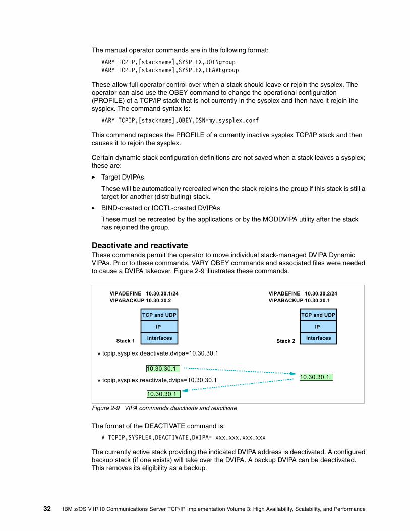
The manual operator commands are in the following format:
VARY TCPIP,[stackname],SYSPLEX,JOINgroup VARY TCPIP,[stackname],SYSPLEX,LEAVEgroup
These allow full operator control over when a stack should leave or rejoin the sysplex. The operator can also use the OBEY command to change the operational configuration (PROFILE) of a TCP/IP stack that is not currently in the sysplex and then have it rejoin the sysplex. The command syntax is:
VARY TCPIP,[stackname],OBEY,DSN=my.sysplex.conf
This command replaces the PROFILE of a currently inactive sysplex TCP/IP stack and then causes it to rejoin the sysplex.
Certain dynamic stack configuration definitions are not saved when a stack leaves a sysplex; these are:
� Target DVIPAs
These will be automatically recreated when the stack rejoins the group if this stack is still a target for another (distributing) stack.
� BIND-created or IOCTL-created DVIPAs
These must be recreated by the applications or by the MODDVIPA utility after the stack has rejoined the group.
Deactivate and reactivate These commands permit the operator to move individual stack-managed DVIPA Dynamic VIPAs. Prior to these commands, VARY OBEY commands and associated files were needed to cause a DVIPA takeover. Figure 2-9 illustrates these commands.
Figure 2-9 VIPA commands deactivate and reactivate
The format of the DEACTIVATE command is:
V TCPIP,SYSPLEX,DEACTIVATE,DVIPA= xxx.xxx.xxx.xxx
The currently active stack providing the indicated DVIPA address is deactivated. A configured backup stack (if one exists) will take over the DVIPA. A backup DVIPA can be deactivated. This removes its eligibility as a backup.
Interfaces
IP
TCP and UDP
VIPADEFINE 10.30.30.1/24VIPABACKUP 10.30.30.2
VIPADEFINE 10.30.30.2/24VIPABACKUP 10.30.30.1
Interfaces
IP
TCP and UDP
v tcpip,sysplex,deactivate,dvipa=10.30.30.1
v tcpip,sysplex,reactivate,dvipa=10.30.30.1 10.30.30.110.30.30.1
10.30.30.1
Stack 1 Stack 2
32 IBM z/OS V1R10 Communications Server TCP/IP Implementation Volume 3: High Availability, Scalability, and Performance

The format of the REACTIVATE command is:
V TCPIP,SYSPLEX,REACTIVATE,DVIPA= xxx.xxx.xxx.xxx
The original stack regains ownership of the DVIPA. A backup DVIPA can be reactivated, making it eligible to function as a backup.
Quiesce and resumeThose commands permit operator-initiated quiesce and resume of individual server applications or full target systems. The ability to quiesce a target system stack or an application instance, without a full system shutdown, is useful for many reasons including the following:
� Planned maintenance of the system or application� Allows existing systems or applications to drain their work queue prior to shutdown� Relieve temporary constraints of resources on target system� Temporary - it does not affect Sysplex Distributor's permanent configuration � Issued on target system being affected� Can also be used to control individual server applications in a SHAREPORT group
The only way to achieve similar capability on earlier z/OS systems was through temporary configuration changes based on OBEYFILE commands.
The format for QUIESCE is:
VARY TCPIP,,SYSPLEX,QUIESCE,options
The options field can be one or several of the following:
TARGET Quiesces all applications on the target stackPORT=xxx Quiesces all applications bound to the specified port on this stackJOBNAME=job name Allows quiesce of a single application in SHAREPORT groupASID=asid Further qualifies jobs being quiesced (such as when dealing with
duplicate job names)
After the QUIESCE, no new TCP connections are sent to the quiesced target (stack or application). Existing TCP connections are maintained (that is, the process is nondisruptive).
The format for RESUME is:
VARY TCPIP,,SYSPLEX,RESUME,options
The options field is [TARGET | PORT | JOBNAME | ASID], with the same parameter formats used for QUIESCE.
Restriction: You cannot use these commands on a DVIPA that was created from VIPARANGE with bind(), ioctl(), or the MODDVIPA utility.
Chapter 2. Virtual IP addressing 33

Use the NETSTAT ALL /-A command to display application status and the quiescing state, as illustrated in Example 2-6.
Example 2-6 Nestat ALL/-A result
MVS TCP/IP NETSTAT CS V1R9 TCPIP NAME: TCPCS 17:40:36 Client Name: CICS1 Client Id: 0000004A Local Socket: 0.0.0.0..27 Foreign Socket: 0.0.0.0..0 Last Touched: 17:09:22 State: Listen
CurrentBacklog: 0000000000 MaximumBacklog: 0000000010 CurrentConnections: 0000000300 SEF: 098 SharePort: WLM RawWeight: 02 NormalizedWeight: 01
Quiesced: Dest
The quiesced line indicates whether this server application has been quiesced for DVIPA Sysplex Distributor workload balancing. A Dest value indicates that this server will receive no new DVIPA Sysplex Distributor workload connections until the server application has been resumed. When the server application is resumed, the quiesced value changes to No.
For additional information about these commands, refer to z/OS Communications Server: IP Configuration Guide, SC31-8775.
2.4 Dynamic VIPA example
We implemented a stack-based (VIPADEFINE and BACKUP) configuration. The following material relates the design, implementation, and operational techniques we used. We worked in two LPARs named SC30 and SC31, and we used TCP/IP stacks named TCPIPC. Our goal was to implement and exercise a failover situation (both automatic and operator-directed), as illustrated in Figure 2-10. To keep the example simple, we used FTP as the application.
Notes:
� These commands must be issued on the system and TCP/IP stack where the application instance is running.
� The commands apply to a single TCP/IP stack's application instance.
� Any Sysplex Distributor timed affinities with the application instance being quiesced will be terminated.
� Existing connections are not affected.
� The QUIESCE state for a TARGET persists for all application instances (existing and new) running on this TCP/IP stack, until the TCP/IP stack is recycled or a V TCPIP,,RESUME,TARGET command is issued.
� RESUME with the TARGET option is the only valid command following a QUIESCE with the TARGET option command.
� When a TCP/IP stack is quiesced, the “ready count” (Rdy) field that appears on the Netstat VDPT display (issued on the Sysplex Distributor routing stack) will be zero (0) for all entries associated with this target TCP/IP stack.
34 IBM z/OS V1R10 Communications Server TCP/IP Implementation Volume 3: High Availability, Scalability, and Performance

Figure 2-10 Stack-managed DVIPA with nondisruptive movement in TAKEBACK
2.4.1 Advantages
When a stack or its underlying z/OS fails, it is not necessary to restart the stack with the same configuration profile on a different z/OS image. After the stack leaves the XCF group, the VIPA address is automatically moved to another stack without the need for human intervention. The new stack will have received information regarding the connections from the original stack and will accept new connections for the DVIPA. The routers are automatically informed about the change. This increases availability because multiple server instances can be started in different stacks.
VIPA takeover allows complete flexibility in the placement of servers within sysplex nodes, not limited to traditional LAN interconnection with MAC addresses. Building on the VIPA concept means that spare adapters do not have to be provided, as long as the remaining adapters have enough capacity to handle the increased load. Spare processing capacity can be distributed across the sysplex rather than on a single node.
2.4.2 Dependencies
External access to our TCP/IP is through DNS and we needed OMPROUTE active to inform DNS about any changes to the DVIPA location. We also needed our TCP/IP stacks configured to support DYNAMICXCF, which is needed for nondisruptive movement of DVIPAs. Finally, we decided to use SYSPLEXROUTING, although this is optional.
2.4.3 Implementation
Our goal was to perform the following:
� Provide the necessary definitions to use VIPA Define and VIPA Backup � Use various commands to display the results of our definitions� Exercise the takeover and takeback function in both automatic and manual operation
DNS
ftp1.mycom.com:10.30.30.1
1 Resolve ftp1.mycom.com 2 Connect to returned address use 10.30.30.1 DVIPA
ftp1,telnet ftp1,telnet
1 10.12.4.223
Connect to 10.30.30.1
10.30.30.1 10.30.30.1 Stack-managed Dynamic VIPA addresses come in very handy for this purpose.
nondisruptive movement of DVIPA address, old session stay in VIPADefine, new go to VIPABackup
FTP
VIPADefine 10.30.30.1
VIPABackup 10.30.30.1
FTP
2
Chapter 2. Virtual IP addressing 35

Figure 2-11 shows the base network configuration used.
Figure 2-11 Base network diagram used for stack-managed implementation
DefinitionsRemember that we are using LPARs SC30 and SC31, and our TCP/IP stack name is TCPIPC in both cases. The following material illustrates only the statements in the PROFILEs (and OMPRoute configuration) that are relevant to our specific task.
Our PROFILE for TCPIPC on SC30 included the statements shown in Example 2-7.
Example 2-7 Our PROFILE for TCPIPC on SC30
IPCONFIG DATAGRAMFWD SYSPLEXROUTING DYNAMICXCF 10.30.20.100 255.255.255.0 8 SOMAXCONN 10 TCPCONFIG TCPSENDBFRSIZE 16K TCPRCVBUFRSIZE 16K SENDGARBAGE FALSE TCPCONFIG RESTRICTLOWPORTS UDPCONFIG RESTRICTLOWPORTS; VIPADEFine/VIPABackup VIPADynamic VIPADEFine MOVEable IMMEDiate 255.255.255.255 10.30.30.1 ENDVIPADynamic
VIPADefine Move 10.30.30.1/32
TCPIPC
FTPDC
VIPABackup 10.30.30.1/32
TCPIPC
FTPDC
Router
10.30.2.232/24 10.30.2.242/24
10.30.2.1/24
XCF110.30.20.100/24
XCF210.30.20.101/24
SC30 SC31
CF
10.12.4.0/24
36 IBM z/OS V1R10 Communications Server TCP/IP Implementation Volume 3: High Availability, Scalability, and Performance

Our PROFILE for TCPIPC on SC31 included the statements shown in Example 2-8.
Example 2-8 Our PROFILE for TCPIPC on SC31
IPCONFIG DATAGRAMFWD SYSPLEXROUTING DYNAMICXCF 10.30.20.101 255.255.255.0 8 SOMAXCONN 10 TCPCONFIG TCPSENDBFRSIZE 16K TCPRCVBUFRSIZE 16K SENDGARBAGE FALSE TCPCONFIG RESTRICTLOWPORTS ; VIPADEFine/VIPABackup VIPADynamic VIPABACKUP 1 MOVEable IMMEDiate 255.255.255.255 10.30.30.1 ENDVIPADynamic
Our OMPRoute definitions included the statements shown in Example 2-9.
Example 2-9 Our OMPRoute definitions
OMPROUTE config ; VIPADefine/VIPABackup vipa ospf_interface ip_address=10.30.30.* subnet_mask=255.255.255.0 attaches_to_area=0.0.0.0 cost0=10
VerificationAfter activating the TCP/IP stacks with these definitions, we used operator commands to display VIPADCFG and VIPADYM status. Example 2-10 shows the commands and results from the two LPARs.
Example 2-10 Display results VIPA definition for TCPIPC (SC30 and 31)
D TCPIP,TCPIPC,N,VIPADCFGRESPONSE=SC30 EZD0101I NETSTAT CS V1R9 TCPIPC 217 DYNAMIC VIPA INFORMATION: VIPA DEFINE: IPADDR/PREFIXLEN: 10.30.30.1/32 MOVEABLE: IMMEDIATE SRVMGR: NO
D TCPIP,TCPIPC,SYSPLEX,VIPADYNRESPONSE=SC30 EZZ8260I SYSPLEX CS V1R9 215 VIPA DYNAMIC DISPLAY FROM TCPIPC AT SC30 LINKNAME: VIPL0A1E1E01 IPADDR/PREFIXLEN: 10.30.30.1/32 ORIGIN: VIPADEFINE TCPNAME MVSNAME STATUS RANK DIST -------- -------- ------ ---- ---- TCPIPC SC30 ACTIVE TCPIPC SC31 BACKUP 001 2 OF 2 RECORDS DISPLAYED
D TCPIP,TCPIPC,SYSPLEX,VIPADYNRESPONSE=SC31 EZZ8260I SYSPLEX CS V1R9 584
Chapter 2. Virtual IP addressing 37

VIPA DYNAMIC DISPLAY FROM TCPIPC AT SC31 LINKNAME: VIPL0A1E1E01 IPADDR/PREFIXLEN: 10.30.30.1/32 ORIGIN: VIPABACKUP TCPNAME MVSNAME STATUS RANK DIST -------- -------- ------ ---- ---- TCPIPC SC31 ACTIVE
We also displayed the OSPF routing table on TCPIPC, as shown in Example 2-11. Note the presence of the local dynamic VIPA 1 with its stack-generated link name.
Example 2-11 Display OMPRoute after DVIPA activation
D TCPIP,TCPIPC,OMPROUTE,RTTABLE000090 DIR* 10.30.30.0 FFFFFF00 1 595 10.30.30.1 000090 DIR* 10.30.30.1 FFFFFFFF 1 595 VIPL0A1E1E01 000090 SPF 10.30.60.0 FFFFFF00 11 595 10.30.2.1 000090 STAT* 10.40.20.100 FFFFFFFF 0 36977 10.30.20.100 000090 STAT* 10.40.20.101 FFFFFFFF 0 36977 10.30.20.100 000090 STAT* 10.40.20.102 FFFFFFFF 0 36977 10.30.20.100 000090 000090 DEFAULT GATEWAY IN USE.
We started the FTP service in the client workstation to use this DVIPA address. We then checked the new status of the session, as shown in Example 2-12.
Example 2-12 Display sessions using DVIPA address
D TCPIP,TCPIPC,N,CON RESPONSE=SC30 EZD0101I NETSTAT CS V1R9 TCPIPC 231 USER ID CONN STATE FTPDC1 00000724 ESTBLSH LOCAL SOCKET: ::FFFF:10.30.30.1..21 FOREIGN SOCKET: ::FFFF:10.12.4.223..2222
2.4.4 Automatic VIPA takeover and takeback
We tried two different options for this exercise, based on MOVE IMMED and MOVE WHENIDLE parameters. When a stack leaves the XCF group (such as resulting from a failure), it causes immediate movement of a DVIPA to its backup stack. These two parameters determine how the original stack takes back the DVIPA from the backup stack when the problem is resolved.
The MOVE IMMED causes the DVIPA to be moved back to the primary stack immediately after the primary stack is available. This might disturb some IP sessions. The MOVE WHENIDLE parameter causes the takeback to be delayed until all connections are finished on the backup stack.
MOVE IMMEDWe defined the primary VIPA IP addresses of 10.30.30.1 on TCPIPC in SC30 and we defined the same VIPA address in TCPIPC on SC31 as the backup. We started our server application (FTP) on both stacks and established connections from a client to the server on TCPIPC in SC30 10.30.30.1.
38 IBM z/OS V1R10 Communications Server TCP/IP Implementation Volume 3: High Availability, Scalability, and Performance
We stopped the TCPIPC to verify that the automatic takeover function would work. Example 2-13 shows the result of this operation. The network is informed, using dynamic routing of OSPF, that the VIPA has moved and all connection requests are routed to the new stack owning the VIPA now. All the other sysplex stacks were informed of the failure through XCF (because the stack left the XCF group) and took steps to recover the failed VIPA. The stack with the highest rank (the only stack) on the backup list for 10.30.30.1 was TCPIPC on SC31.
Example 2-13 Display after the stopped of TCPIC in SC30
EZZ4201I TCP/IP TERMINATION COMPLETE FOR TCPIPC IEF352I ADDRESS SPACE UNAVAILABLE $HASP395 TCPIPC ENDED EZZ8301I VIPA 10.30.30.1 TAKEN OVER FROM TCPIPC ON SC30
D TCPIP,TCPIPC,SYSPLEX,VIPADEZZ8260I SYSPLEX CS V1R9 512 VIPA DYNAMIC DISPLAY FROM TCPIPC AT SC31 LINKNAME: VIPL0A1E1E01 IPADDR/PREFIXLEN: 10.30.30.1/32 ORIGIN: VIPABACKUP TCPNAME MVSNAME STATUS RANK DIST -------- -------- ------ ---- ---- TCPIPC SC31 ACTIVE 1 OF 1 RECORDS DISPLAYED
RESPONSE=SC31 EZD0101I NETSTAT CS V1R9 TCPIPC 516 DYNAMIC VIPA INFORMATION: VIPA BACKUP: IPADDR/PREFIXLEN: 10.30.30.1 RANK: 001 MOVEABLE: SRVMGR: END OF THE REPORT
D TCPIP,TCPIPC,N,CON(Display of new ftp session using 10.30.30.1 in VIPABACKUP)FTPDC1 00000831 ESTBLSH LOCAL SOCKET: ::FFFF:10.30.30.1..21 FOREIGN SOCKET: ::FFFF:10.12.4.223..2234 FTPDC1 0000082D ESTBLSH LOCAL SOCKET: ::FFFF:10.30.30.1..21 FOREIGN SOCKET: ::FFFF:10.12.4.223..2233
We then restarted the original TCPIPC stack on SC30, including the FTP application. The VIPA address 10.30.10.1 returned automatically from SC31 to SC30. Example 2-14 shows the console messages associated with this action.
Example 2-14 Console message after restarting the failed TCP/IP stack in SC30
EZZ8302I VIPA 10.30.30.1 TAKEN FROM TCPIPC ON SC31 EZZ8303I VIPA 10.30.30.1 GIVEN TO TCPIPC ON SC30
Note: A “failure” like this is disruptive to connections that are active when the takeover occurs. However, most TCP/IP applications recover from this automatically. Movements during takeback are nondisruptive.
Chapter 2. Virtual IP addressing 39

TCPIPC in SC31 had the VIPA 10.30.30.1 active and had some active connections when the address was taken back by SC30. These active connections were not broken. Example 2-15 shows the existing to connections to SC31. However, TCPIPC in SC30 is now receiving all new connections. Example 2-16 shows the creation of a new FTP connection.
Example 2-15 Display of the connections to SC31 after the takeback to SC30
D TCPIP,TCPIPC,N,VCRT EZD0101I NETSTAT CS V1R9 TCPIPC 592 DYNAMIC VIPA CONNECTION ROUTING TABLE: DEST: 10.30.30.1..21 SOURCE: 10.12.4.223..2252 DEST: 10.30.30.1..21 FTPDC1 00000B05 FINWT2 LOCAL SOCKET: ::FFFF:10.30.30.1..21 FOREIGN SOCKET: ::FFFF:10.12.4.223..2252 OMPC 0000002B ESTBLSH
Example 2-16 shows the VIPA connection routing table (VCRT) in both stacks, which include the old and new connections.
Example 2-16 Display of the older session in SC31 and new session in SC30 after the takeback
RESPONSE=SC30 EZD0101I NETSTAT CS V1R9 TCPIPC 121 DYNAMIC VIPA CONNECTION ROUTING TABLE: DEST: 10.30.30.1..21 SOURCE: 10.12.4.223..2256 DESTXCF: 10.30.20.100 2 DEST: 10.30.30.1..21 SOURCE: 10.12.4.223..2252 DESTXCF: 10.30.20.101 1 SOURCE: 10.12.4.223..2253 DESTXCF: 10.30.20.101 1 3 OF 3 RECORDS DISPLAYED END OF THE REPORT
D TCPIP,TCPIPC,N,CONN EZD0101I NETSTAT CS V1R9 TCPIPC 123 FTPDC1 0000003A ESTBLSH LOCAL SOCKET: ::FFFF:10.30.30.1..21 FOREIGN SOCKET: ::FFFF:10.12.4.223..2256
In this example, the numbers correspond to the following information:
1. DestXCF 10.30.20.101 are connections that are still active on SC31.
2. DestXCF 10.30.20.100 is the new FTP connection to TCPIPC in SC30 after the takeback.
MOVE WHENIDLEIn this case, we used the same definitions and processes as for the last example, except that we changed the parameter MOVE IMMED to MOVE WHENIDLE in VIPA DEFINE statements.
The behavior was exactly the same as in the previous scenario. TCPIPC was informed of the failure through XCF and took steps to recover the failed DVIPA. TCPIPC on SC31 dynamically defined and activated this DVIPA address.
40 IBM z/OS V1R10 Communications Server TCP/IP Implementation Volume 3: High Availability, Scalability, and Performance

We then restarted TCPIPC in SC30 and started a new connection to DVIPA address 10.30.30.1. Because we defined this DVIPA as MOVE WHENIDLE, the DVIPA was not taken back to SC30 because there were active connections to 10.30.30.1 on SC31.
Example 2-17 shows a new FTP connection to DVIPA address 10.30.30.1 and shows that this connection was established with TCPIPC in SC31, because the DVIPA has not yet been taken back.
Example 2-17 New connection still going to SC31
FTPDC1 00000044 ESTBLSH LOCAL SOCKET: ::FFFF:10.30.30.1..21 FOREIGN SOCKET: ::FFFF:10.12.4.223..2362 FTPDC1 0000012B ESTBLSH LOCAL SOCKET: ::FFFF:10.30.30.1..21 FOREIGN SOCKET: ::FFFF:10.12.4.223..2409
As long as the sessions exist in SC31, the active DVIPA stays on the stack in SC31. Example 2-18 shows this result.
Example 2-18 VIPA active in SC31
RESPONSE=SC30 EZZ8260I SYSPLEX CS V1R9 378 VIPA DYNAMIC DISPLAY FROM TCPIPC AT SC30 IPADDR: 10.30.30.1 ORIGIN: VIPADEFINE TCPNAME MVSNAME STATUS RANK DIST -------- -------- ------ ---- ---- TCPIPC SC31 ACTIVE TCPIPC SC30 BACKUP 255 IPADDR: 255.255.255.255 TCPNAME MVSNAME STATUS RANK DIST -------- -------- ------ ---- ---- TCPIPC SC31 BACKUP 001
After all the FTP sessions are closed, the takeback is performed, and the active DVIPA returns to SC30. Example 2-19 shows the result of this operation.
Example 2-19 Takeback DVIPA after close sessions
EZZ8303I VIPA 10.30.30.1 GIVEN TO TCPIPC ON SC30 EZZ8301I VIPA 10.30.30.1 TAKEN OVER FROM TCPIPC ON SC31
Note: The VIPADEFINE MOVEABLE WHENIDLE parameter might be retired in a future release, because MOVE IMMED is the most common choice.
Chapter 2. Virtual IP addressing 41

Deactivate and reactivate operator commandsUsing the same configuration, we issued a DEACTIVATE command to force a takeover process. This moved the active DVIPA address from SC30 to SC31 in the same way a failure in SC30 would cause the move. Example 2-20 shows the results of this manual operation.
Example 2-20 Display the result of deactivate command in SC30
V TCPIP,TCPIPC,SYSPLEX,DEACTIVATE,DVIPA=10.30.30.1 EZZ0060I PROCESSING COMMAND: VARY TCPIP,TCPIPC,SYSPLEX,DEACTIVATE,DVIPA=10.30.30.1 EZD1197I THE VARY TCPIP,,SYSPLEX,DEACTIVATE,DVIPA COMMAND COMPLETED
D TCPIP,TCPIPC,N,VIPAD EZD0101I NETSTAT CS V1R9 TCPIPC 571 DYNAMIC VIPA: IPADDR/PREFIXLEN: 10.30.30.1/32 STATUS: QUIESCING ORIGIN: VIPADEFINE
Example 2-21 shows that SC31 now has the DVIPA active.
Example 2-21 System SC31 assumes the VIPA address after the deactivate
RO SC31,D TCPIP,TCPIPC,N,VIPAD RESPONSE=SC31 EZD0101I NETSTAT CS V1R9 TCPIPC 105 DYNAMIC VIPA: IPADDR/PREFIXLEN: 10.30.30.1/32 STATUS: ACTIVE ORIGIN: VIPABACKUP IPADDR/PREFIXLEN: 255.255.255.255 STATUS: BACKUP ORIGIN: VIPABACKUP
We next used REACTIVATE to start the takeback function, moving the DVIAP address from SC31 to SC30. We issued this command for SC30. Example 2-22 shows the results of this manual operation.
Example 2-22 Result of takeback operation using reactivate command in SC30
V TCPIP,TCPIPC,SYSPLEX,REACTIVATE,DVIPA=10.30.30.1 EZZ0060I PROCESSING COMMAND: VARY TCPIP,TCPIPC,SYSPLEX,REACTIVATE,DV IPA=10.30.30.1 EZZ8302I VIPA 10.30.30.1 TAKEN FROM TCPIPC ON SC31 EZZ8303I VIPA 10.30.30.1 GIVEN TO TCPIPC ON SC30 EZD1189I THE VARY TCPIP,,SYSPLEX,REACTIVATE,DVIPA COMMAND COMPLETED SUCCESSFULLY
42 IBM z/OS V1R10 Communications Server TCP/IP Implementation Volume 3: High Availability, Scalability, and Performance

We had started two FTP sessions to TCPIPC in SC31 while that system had the active DVIPA address. After the REACTIVATE we started more two FTP sessions. Example 2-23 shows the VIPA Connection Routing Table (VCRT) in both stacks, which include the old and new connections. DestXCF 10.30.20.101 has the old connections that are still active on SC31. DestXCF 10.30.20.100 has the new FTP connection to TCPIPC in SC30.
Example 2-23 Display VCRT shows the old and new sessions SC31 with moving status
D TCPIP,TCPIPC,SYSPLEX,VIPADYNEZZ8260I SYSPLEX CS V1R9 794 RESPONSE=SC30 EZZ8260I SYSPLEX CS V1R9 794 VIPA DYNAMIC DISPLAY FROM TCPIPC AT SC30 LINKNAME: VIPL0A1E1E01 IPADDR/PREFIXLEN: 10.30.30.1/32 ORIGIN: VIPADEFINE TCPNAME MVSNAME STATUS RANK DIST -------- -------- ------ ---- ---- TCPIPC SC30 ACTIVE TCPIPC SC31 MOVING
D TCPIP,TCPIPC,N,VCRT EZD0101I NETSTAT CS V1R9 TCPIPC 805 DYNAMIC VIPA CONNECTION ROUTING TABLE: DEST: 10.30.30.1..20 1 SOURCE: 10.12.4.223..2648 DESTXCF: 10.30.20.100DEST: 10.30.30.1..20 SOURCE: 10.12.4.223..2639 DESTXCF: 10.30.20.101 DEST: 10.30.30.1..20 2 SOURCE: 10.12.4.223..2642 DESTXCF: 10.30.20.101 DEST: 10.30.30.1..21 SOURCE: 10.12.4.223..2643 DESTXCF: 10.30.20.100
In this example, the numbers correspond to the following information:
1. DestXCF 10.30.20.100 are the new FTP connections to TCPIPC in SC30 after the takeback.
2. DestXCF 10.30.20.101 are the old connections that are still active on SC31.
Note: The existing connections during takeback remain up. They are not disrupted.
After all sessions to the backup are closed, then new connections go to the primary DVIPA machine. The moving status continues until the last connections end, then the status changes to backup. (This assumes that MOVE WHENIDLE is in effect.)
Chapter 2. Virtual IP addressing 43

44 IBM z/OS V1R10 Communications Server TCP/IP Implementation Volume 3: High Availability, Scalability, and Performance

Chapter 3. VIPA without dynamic routing
As previously mentioned, we formerly recommended using a dynamic routing protocol in your mainframes for high availability. Now, innovative designs have leveraged z/OS support of Address Resolution Protocol (ARP) takeover to achieve comparable availability without using a dynamic routing protocol. Here we explain how to design and implement high availability for your z/OS Communications Server environment without dynamic routing.
This chapter discusses the following topics.
3
Section Topic
3.1, “Basic concepts” on page 46” Background information and an explanation of why this solution can be important in typical environments
3.2, “High availability without dynamic routing” on page 51
Key design points and the steps through detailed implementation.
3.3, “High availability scenarios” on page 57 Failing scenarios to test and verify the high availability environment we implemented
3.4, “Debugging tips” on page 62 Summary of debugging approaches useful when working with layer two definitions
© Copyright IBM Corp. 2009. All rights reserved. 45

3.1 Basic concepts
High availability designs that do not use dynamic routing protocols (which are part of TCP/IP) achieve availability based on local area networking (LAN) capabilities instead (such LAN capabilities are also often referred to as layer 2 functions because LANs constitute layers 1 and 2 of the seven-layer OSI networking model).
The most fundamental of those capabilities is the ability to transfer an IP address from a failing (or failed) physical interface or stack to a different physical interface or stack. In an z/OS Communications Server environment, dynamic movement of an IP address (without the use of dynamic routing) is called ARP takeover, and it requires OSA-Express adapters (in QDIO mode).
In addition, if you want to move an IP address from one adapter to another within a system, you must also set up Static Virtual IP Addresses (VIPA). If you want to implement dynamic movement of an IP address from one TCP/IP stack to another (including a stack on a completely different system), you must set up Dynamic Virtual IP Addressing (DVIPA), which, in turn, requires Sysplex XCF communications.
ARP takeover uses LAN broadcast protocols. Therefore, to use ARP takeover, all of the systems in your sysplex must be connected to the same LAN (or virtual LAN, VLAN) and thus, in the same TCP/IP subnet (also called flat network connectivity). Also, ARP takeover does not provide protection from failures in routers or switches in the network. Backup and recovery for these elements must be considered separately.
A flat network is one in which all stacks can reach each other without going through intermediate bridges or routers that transform IP addresses. Expressed a different way, a flat network is contained in one network segment or subnet. It is one broadcast domain.
Stacks within a flat network communicate with each other at layer 2 of the OSI model. Layer 2 frames are switched based on MAC addresses. (Layer 3 frames are switched based on IP addresses.) A flat network does not preclude the incorporation of transparent switches or bridges, and it might support up to a few hundred stations.
In the design discussed here, all z/OS systems are directly attached to the same IP subnet. A primary DVIPA TCP/IP stack and a backup DVIPA stack exist. Each has a unique MAC address.
If the backup DVIPA stack detects a failure of the primary stack (when it leaves the XCF group), it takes over the IP address of the primary stack but retains its unique MAC address. It then responds with its own MAC address to ARP requests that are searching for the host with the required IP address (which has not changed with the move from the primary to the backup stack).
No external routing changes are needed as a result of the move from the primary stack to the backup stack. Therefore, a dynamic routing protocol is not required.
Note: Virtual IP Addressing is introduced, along with implementation scenarios, in Chapter 2, “Virtual IP addressing” on page 13.
46 IBM z/OS V1R10 Communications Server TCP/IP Implementation Volume 3: High Availability, Scalability, and Performance

3.1.1 ARP takeover
ARP takeover is a function that allows traffic to be redirected from a failing OSA connection to another OSA connection. This function is supported with IPv4 and IPv6 OSA interfaces.
When an OSA DEVICE defined in a TCP/IP stack is started, all IP addresses associated with that OSA port in QDIO mode (which is device type MPCIPA in the TCP/IP profile) are dynamically downloaded to the OSA card.
If an OSA port fails while there is a backup OSA port available on the same subnetwork, then TCP/IP informs the backup adapter as to which IP addresses (real and VIPA) to take over and network connections are maintained. After it is set up correctly, the fault tolerance provided by the ARP takeover function is automatic. Figure 3-1 shows the ARP Takeover process.
Figure 3-1 ARP takeover environment
Note: If you want to use the ARP takeover function, use your OSA-Express or OSA-Express2 port in QDIO mode. If the port is defined in non-QDIO mode (device type LCS in the TCP/IP profile), then you must use OSA/SF to build and activate a configuration that identifies the multiple IP addresses that might be used with the adapter. In a DVIPA environment (or a simple OSA takeover environment), the use of QDIO mode simplifies setup and management.
Note: For demonstration purposes, we show a single-switch environment in our examples. However, to avoid single points of failure, always separate your OSA connections across multiple switches.
TCPIPB
10.1.100.222
C : \ ping 10.1.2.21
OSA2080L OSA-Express
10.1.2.21
OSA20A0LOSA-Express
10.1.2.22
MAC ADDR00096B1A74C2
MAC ADDR00096B1A7490
z/OS -LPAR A24
SWITCH
Before ARP Takeover
SVIPA10.1.2.20
route 10.1.2.0/24 [1/0] via 10.1.2.240, VLAN10
VLAN10
VIPAOWNER
VLAN30
Chapter 3. VIPA without dynamic routing 47
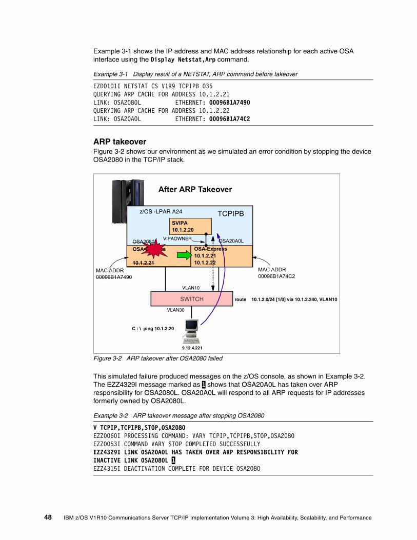
Example 3-1 shows the IP address and MAC address relationship for each active OSA interface using the Display Netstat,Arp command.
Example 3-1 Display result of a NETSTAT, ARP command before takeover
EZD0101I NETSTAT CS V1R9 TCPIPB 035 QUERYING ARP CACHE FOR ADDRESS 10.1.2.21 LINK: OSA2080L ETHERNET: 00096B1A7490 QUERYING ARP CACHE FOR ADDRESS 10.1.2.22 LINK: OSA20A0L ETHERNET: 00096B1A74C2
ARP takeoverFigure 3-2 shows our environment as we simulated an error condition by stopping the device OSA2080 in the TCP/IP stack.
Figure 3-2 ARP takeover after OSA2080 failed
This simulated failure produced messages on the z/OS console, as shown in Example 3-2. The EZZ4329I message marked as 1 shows that OSA20A0L has taken over ARP responsibility for OSA2080L. OSA20A0L will respond to all ARP requests for IP addresses formerly owned by OSA2080L.
Example 3-2 ARP takeover message after stopping OSA2080
V TCPIP,TCPIPB,STOP,OSA2080 EZZ0060I PROCESSING COMMAND: VARY TCPIP,TCPIPB,STOP,OSA2080 EZZ0053I COMMAND VARY STOP COMPLETED SUCCESSFULLY EZZ4329I LINK OSA20A0L HAS TAKEN OVER ARP RESPONSIBILITY FOR INACTIVE LINK OSA2080L 1 EZZ4315I DEACTIVATION COMPLETE FOR DEVICE OSA2080
TCPIPB
9.12.4.221
C : \ ping 10.1.2.20
OSA2080L OSA-Express
10.1.2.21
OSA20A0LOSA-Express10.1.2.2110.1.2.22
MAC ADDR00096B1A74C2
MAC ADDR00096B1A7490
z/OS -LPAR A24
SWITCH
After ARP Takeover
SVIPA10.1.2.20
route 10.1.2.0/24 [1/0] via 10.1.2.240, VLAN10
VLAN10
VIPAOWNER
VLAN30
48 IBM z/OS V1R10 Communications Server TCP/IP Implementation Volume 3: High Availability, Scalability, and Performance

Example 3-3 shows a display of the ARP cache tables from TCPIPB.
Example 3-3 Display results of a NETSTAT, ARP command after takeover
D TCPIP,TCPIPB,N,ARPEZD0101I NETSTAT CS V1R9 TCPIPB 063 QUERYING ARP CACHE FOR ADDRESS 10.1.2.22 LINK: OSA20A0L ETHERNET: 00096B1A74C2 1 QUERYING ARP CACHE FOR ADDRESS 10.1.2.21 LINK: OSA20A0L ETHERNET: 00096B1A74C2 1
Both IP addresses were pointed to the same MAC address marked as 1, which was associated with the link OSA20A0L. TCPIPB notified all hosts on the LAN by broadcasting gratuitous ARPs when the link (OSA2080L) stopped.
Example 3-4 shows the status of VIPAOWNER after taking over.
Example 3-4 Display result of a NETSTAT, DEV command after takeover
D TCPIP,TCPIPB,NETSTAT,DEVLANGROUP: 00002 LNKNAME LNKSTATUS ARPOWNER VIPAOWNER ------- --------- -------- --------- OSA20A0L ACTIVE OSA20A0L YES 1 OSA2080L NOT ACTIVE OSA20A0L 2 NO
In this example, the numbers correspond to the following information:
1. The VIPAOWNER was switched to link OSA20A0L.
2. Link OSA2080L was inactive, and was no longer the ARPOWNER.
Chapter 3. VIPA without dynamic routing 49
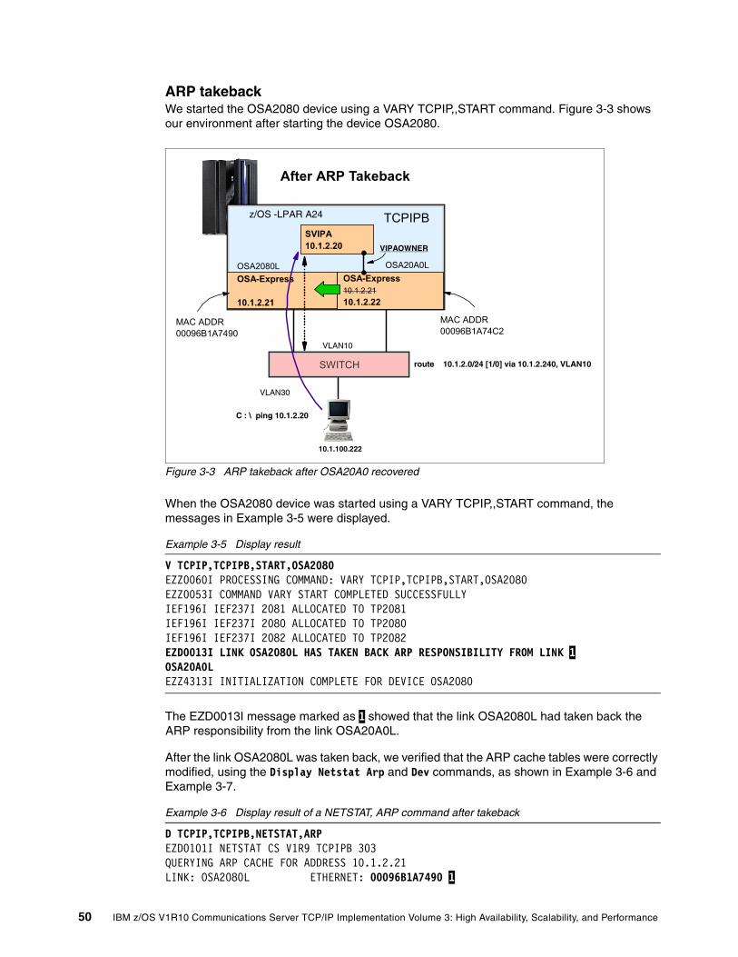
ARP takebackWe started the OSA2080 device using a VARY TCPIP,,START command. Figure 3-3 shows our environment after starting the device OSA2080.
Figure 3-3 ARP takeback after OSA20A0 recovered
When the OSA2080 device was started using a VARY TCPIP,,START command, the messages in Example 3-5 were displayed.
Example 3-5 Display result
V TCPIP,TCPIPB,START,OSA2080 EZZ0060I PROCESSING COMMAND: VARY TCPIP,TCPIPB,START,OSA2080 EZZ0053I COMMAND VARY START COMPLETED SUCCESSFULLY IEF196I IEF237I 2081 ALLOCATED TO TP2081 IEF196I IEF237I 2080 ALLOCATED TO TP2080 IEF196I IEF237I 2082 ALLOCATED TO TP2082 EZD0013I LINK OSA2080L HAS TAKEN BACK ARP RESPONSIBILITY FROM LINK 1 OSA20A0L EZZ4313I INITIALIZATION COMPLETE FOR DEVICE OSA2080
The EZD0013I message marked as 1 showed that the link OSA2080L had taken back the ARP responsibility from the link OSA20A0L.
After the link OSA2080L was taken back, we verified that the ARP cache tables were correctly modified, using the Display Netstat Arp and Dev commands, as shown in Example 3-6 and Example 3-7.
Example 3-6 Display result of a NETSTAT, ARP command after takeback
D TCPIP,TCPIPB,NETSTAT,ARPEZD0101I NETSTAT CS V1R9 TCPIPB 303 QUERYING ARP CACHE FOR ADDRESS 10.1.2.21 LINK: OSA2080L ETHERNET: 00096B1A7490 1
TCPIPB
10.1.100.222
C : \ ping 10.1.2.20
OSA2080L OSA-Express
10.1.2.21
OSA20A0LOSA-Express10.1.2.2110.1.2.22
MAC ADDR00096B1A74C2
MAC ADDR00096B1A7490
z/OS -LPAR A24
SWITCH
After ARP Takeback
SVIPA10.1.2.20
route 10.1.2.0/24 [1/0] via 10.1.2.240, VLAN10
VLAN10
VIPAOWNER
VLAN30
50 IBM z/OS V1R10 Communications Server TCP/IP Implementation Volume 3: High Availability, Scalability, and Performance

QUERYING ARP CACHE FOR ADDRESS 10.1.2.22 LINK: OSA20A0L ETHERNET: 00096B1A74C23 OF 3 RECORDS DISPLAYED END OF THE REPORT
In this example, the number corresponds to the following information:
1. The ARP cache now referenced the real MAC for address 10.1.2.21. A gratuitous ARP was broadcasted on the LAN by the TCPIP stack, and the ARP cache in the switch was updated with the correct MAC addresses.
Example 3-7 Display result of a NETSTAT, DEV command after takeback
D TCPIP,TCPIPB,NETSTAT,DEVLANGROUP: 00002 LNKNAME LNKSTATUS ARPOWNER VIPAOWNER ------- --------- -------- --------- OSA20A0L ACTIVE OSA20A0L YES 2 OSA2080L ACTIVE OSA2080L NO 1
In this example, the number corresponds to the following information:
2. The link OSA2080L was now active and had its own ARPOWNER status back. However, link OSA20A0L kept the VIPAOWNER. This is because a VIPA belongs to a stack and not to a particular interface; therefore, it does not matter which OSA is the VIPAOWNER.
3.2 High availability without dynamic routing
In our environment, we used two OSA adapters in QDIO mode, connected to two switches. We used a unique VLAN (VLAN 10), spanning our switches, and connected our hosts to that VLAN.
We worked in two LPARs, A23 (system SC30) and A24 (system SC31), using static routing between them. Our DVIPA failover implementation moves the active IP address from one LPAR to the other when needed.
Our design had the following dependencies:
� We needed separate LAN adapters for each stack. We used OSA-Express2 adapters in QDIO mode. QDIO mode is recommended because the OSA internal IP tables (OATs) are updated automatically. Other LAN interfaces, such as channel-attached routers, cannot be used in the high availability configuration described in this chapter.
� All z/OS images must be connected to the same LAN segment, so that all adapters receive broadcast frames.
� This scenario is suitable for a subnet with a small number of hosts. If the subnet had more hosts, then we must consider the potential effects of LAN broadcast (sometimes called broadcast storms). This exposure is not directly related to the DVIPA operation we are describing, but should be considered when designing high availability network environments.
� To show a flat network scenario, all resources in VLAN 10, including the VIPA addresses, belong to the same subnet.
Chapter 3. VIPA without dynamic routing 51

This design has the following advantages:
� It is simple, easy to configure, and avoids the complexities of implementing dynamic routing.
� No additional routers or router paths are required.
� This design supports DVIPA takeover and takeback functions as well as distributed DVIPA.
3.2.1 Implementation
Figure 3-4 illustrates our working environment. The OSA-Express2 CHPIDs were defined as OSD types, causing them to work in QDIO mode.
Figure 3-4 Diagram of our working environment
Telnet
X.11
10.1.7.11
FTP
XCF
X.22
10.1.7.21
VIPABackup 10.1.2.199VIPARange 10.1.2.99
SC30 SC31
VIPADEFine 10.1.2.199VIPARange 10.1.2.99
OSA4
FTPTelnet Telnet
X.12 X.21
TCPIPA TCPIPB
Cisco1
Flat Network 10.1.2.0/24VLAN 10
HSRP/VRRP Switch 1
x.240
CEC
Y.222
Switch 2
x.220X=10.1.2
Two LPARs in same CEC
VLAN 30Y=10.1.100
y.220y.240
OSA20A0OSA2080
52 IBM z/OS V1R10 Communications Server TCP/IP Implementation Volume 3: High Availability, Scalability, and Performance

Example 3-8 and Example 3-9 list the relevant statements in our TCP/IP profiles for the two LPARs. The following key items should be noted:
� We configured the two OSA ports to use the same VLAN (VLAN 10) 1.
� We created static route and default route definitions to both OSA ports that belong to the VLANID. By doing this, we had high availability at the interface level. One is a backup of the other 2.
� We defined two DVIPA addresses using VIPADEFine and VIPABackup in the stack 3 and VIPARange at the application level 4.
� We defined the FTP application to bind() to a specific address (DVIPA) instead of INADDR_ANY by using the server bind control that is implemented through the BIND keyword on the PORT statement 5.
Example 3-8 TCP/IP profile in SC30
IPCONFIG MULTIPATH IQDIOR DATAGRAMFWDIPCONFIG SOURCEVIPADEVICE OSA2080 MPCIPA LINK OSA2080L IPAQENET OSA2080 VLANID 10 1 DEVICE OSA20A0 MPCIPA LINK OSA20A0L IPAQENET OSA20A0 VLANID 10 1 HOME10.1.2.11 OSA2080L10.1.2.12 OSA20A0LBEGINROUTESROUTE 10.1.2.0 255.255.255.0 = OSA2080L mtu defaultsize 2 ROUTE 10.1.2.0 255.255.255.0 = OSA20A0L mtu defaultsizeROUTE DEFAULT 10.1.2.240 OSA2080L mtu defaultsize ROUTE DEFAULT 10.1.2.220 OSA20A0L mtu defaultsize ENDROUTES;Test flat network startVIPADynamicVIPARange DEFINE MOVEable NONDISRUPTive 255.255.255.255 10.1.2.199 4 VIPADEFINE MOVE IMMED 255.255.255.255 10.1.2.99 3 ENDVIPADYNAMIC ;Test flat network end;Bind to Dynamic VIPA SC30 and SC31:PORT 20 TCP * NOAUTOLOG ; FTP Server 21 TCP OMVS BIND 10.1.2.199 ; control port 5
Chapter 3. VIPA without dynamic routing 53

Example 3-9 shows our TCP/IP profile in SC31.
Example 3-9 TCP/IP profile in SC31
IPCONFIG MULTIPATH IQDIOR DATAGRAMFWDIPCONFIG SOURCEVIPADEVICE OSA2080 MPCIPA LINK OSA2080L IPAQENET OSA2080 VLANID 10 1 DEVICE OSA20A0 MPCIPA LINK OSA20A0L IPAQENET OSA20A0 VLANID 10 1 HOME10.1.2.21 OSA2080L10.1.2.22 OSA20A0LBEGINROUTESROUTE 10.1.2.0 255.255.255.0 = OSA2080L mtu defaultsize 2 ROUTE 10.1.2.0 255.255.255.0 = OSA20A0L mtu defaultsizeROUTE DEFAULT 10.1.2.240 OSA2080L mtu defaultsize ROUTE DEFAULT 10.1.2.220 OSA20A0L mtu defaultsize ENDROUTES;Test flat network startVIPADynamicVIPARange DEFINE MOVEable NONDISRUPTive 255.255.255.255 10.1.2.199 4 VIPABackup 1 MOVEable IMMEDiate 255.255.255.255 10.1.2.99 3 ENDVIPADYNAMIC ;Test flat network end 20 TCP * NOAUTOLOG ; FTP Server 21 TCP OMVS BIND 10.1.2.199 ; control port 5
We defined our VLAN in both switches, as shown in Example 3-10 and Example 3-11 (6). These two examples also illustrate ping operations between the routers and the OSA ports.
Example 3-10 Switch 1 setup
Router(config)#interface vlan 10 6Router(config-if)#ip address 10.1.2.240 255.255.255.0Router(config-if)#no shutRouter(config-if)#end
Router# ping 10.1.2.11Type escape sequence to abort.Sending 5, 100-byte ICMP Echos to 10.1.2.11, timeout is 2 seconds:!!!!!Success rate is 100 percent (5/5), round-trip min/avg/max = 1/1/4 msRouter#wr memBuilding configuration...
Example 3-11 illustrates the switch 2 setup.
Example 3-11 Switch 2 setup
Router(config)#interface vlan 10 6Router(config-if)#ip address 10.1.2.220 255.255.255.0Router(config-if)#no shutRouter(config-if)#end
Router# ping 10.1.2.21Type escape sequence to abort.
54 IBM z/OS V1R10 Communications Server TCP/IP Implementation Volume 3: High Availability, Scalability, and Performance

Sending 5, 100-byte ICMP Echos to 10.1.2.21, timeout is 2 seconds:!!!!!Success rate is 100 percent (5/5), round-trip min/avg/max = 1/1/4 msRouter#wr memBuilding configuration...
3.2.2 Verification
To verify that our network was operational, we first used NETSTAT to check the routing configuration, as shown in Example 3-12.
Example 3-12 Flat network result display routes in normal operation of SC30 and SC31
D TCPIP,TCPIPA,N,ROUTE RESPONSE=SC30 EZD0101I NETSTAT CS V1R9 TCPIPA 944 IPV4 DESTINATIONS DESTINATION GATEWAY FLAGS REFCNT INTERFACE DEFAULT 10.1.2.240 UGS 000001 OSA2080L 1DEFAULT 10.1.2.220 UGS 000000 OSA20A0L 10.1.2.0/24 0.0.0.0 UZ 000000 OSA2080L 10.1.2.0/24 0.0.0.0 UZ 000000 OSA20A0L 10.1.2.99/32 0.0.0.0 UH 000000 VIPL0A010263 10.1.2.11/32 0.0.0.0 UH 000000 OSA2080L 10.1.2.12/32 0.0.0.0 UH 000000 OSA20A0L RESPONSE=SC31 EZD0101I NETSTAT CS V1R9 TCPIPB 928 IPV4 DESTINATIONS DESTINATION GATEWAY FLAGS REFCNT INTERFACE DEFAULT 10.1.2.240 UGS 000000 OSA2080L 1 DEFAULT 10.1.2.220 UGS 000000 OSA20A0L 10.1.2.0/24 0.0.0.0 UZ 000000 OSA2080L 10.1.2.0/24 0.0.0.0 UZ 000000 OSA20A0L 10.1.2.99/32 0.0.0.0 UH 000000 VIPL0A01026310.1.2.21/32 0.0.0.0 UH 000000 OSA20A0L 10.1.2.22/32 0.0.0.0 UH 000000 OSA20C0L
Note the two default gateways to routers 10.1.2.240 and 10.1.2.220 (1) in Example 3-12.
A NETSTAT with a VIPADCFG operand provides information about the DVIPA configuration in each stack where the command is issued. The results are illustrated in Example 3-13.
Example 3-13 Display NETSTAT Dvipa config in SC30 and SC31
D TCPIP,TCPIPA,N,VIPADCFGRESPONSE=SC30EZD0101I NETSTAT CS V1R9 TCPIPA 947 DYNAMIC VIPA INFORMATION: VIPA DEFINE: IPADDR/PREFIXLEN: 10.1.2.99/32 MOVEABLE: IMMEDIATE SRVMGR: NO VIPA RANGE: IPADDR/PREFIXLEN: 10.1.2.199/32 MOVEABLE: NONDISR RESPONSE=SC31
Chapter 3. VIPA without dynamic routing 55

EZD0101I NETSTAT CS V1R9 TCPIPB 938 DYNAMIC VIPA INFORMATION: VIPA BACKUP: IPADDR/PREFIXLEN: 10.1.2.99 RANK: 001 MOVEABLE: SRVMGR: VIPA RANGE: IPADDR/PREFIXLEN: 10.1.2.199/32MOVEABLE: NONDISR
We used two TCP/IP applications, TELNET and FTP. Both were used from a client workstation at address 10.1.100.222. The Telnet client was configured to access the VIPADEFine 1 10.1.2.99. The FTP client was started to access the VIPARange 10.1.2.199 2. This DVIPA address only appears in the home list after the application FTP server is started.
A NETSTAT with a VIPADYN operand provides information about DVIPA status in each stack where the command is issued. The results are illustrated in Example 3-14.
Example 3-14 Display NETSTAT Dvipa status in SC30 and SC31
D TCPIP,TCPIPA,N,VIPADYNRESPONSE=SC30 EZD0101I NETSTAT CS V1R9 TCPIPA 956 DYNAMIC VIPA: IPADDR/PREFIXLEN: 10.1.2.99/32 1 STATUS: ACTIVE ORIGIN: VIPADEFINE DISTSTAT: after we start the FTP the VIPARange address appearsLINKNAME: VIPL0A0102C7 IPADDR/PREFIXLEN: 10.1.2.199/32 2 ORIGIN: VIPARANGE BIND TCPNAME MVSNAME STATUS RANK DIST -------- -------- ------ ---- ---- TCPIPA SC30 ACTIVE
RESPONSE=SC31 EZD0101I NETSTAT CS V1R9 TCPIPB 941 DYNAMIC VIPA: IPADDR/PREFIXLEN: 10.1.2.99/32 STATUS: BACKUP ORIGIN: VIPABACKUP DISTSTAT:
A NETSTAT with a CONN operand, shown in Example 3-15, provides connection information.
Example 3-15 Telnet and FTP to DVIPA address in use
D TCPIP,TCPIPA,N,CONN EZD0101I NETSTAT CS V1R9 TCPIPA 964 USER ID CONN STATE TCPIPB 00000288 ESTBLSH LOCAL SOCKET: ::FFFF:10.1.2.99..23 FOREIGN SOCKET: ::FFFF:10.1.100.222..3640FTPDC1 000000BF ESTBLSH LOCAL SOCKET: ::FFFF:10.1.2.199..21 FOREIGN SOCKET: ::FFFF:10.1.100.222..3820
56 IBM z/OS V1R10 Communications Server TCP/IP Implementation Volume 3: High Availability, Scalability, and Performance

3.3 High availability scenarios
The examples that we discuss here are not designed to be indicative of typical failures. Instead, they can help you to understand various recovery and transfer processes. We examine the following areas of interest:
� Adapter interface failure� Application movement� Stack failure
3.3.1 Adapter interface failure
We stopped the OSA adapter (OSA2080) on our primary system to verify that the connection from the client workstation continued to function during the takeover by the backup system. The failure scenario is illustrated in Figure 3-5.
Figure 3-5 High availability for an adapter failure
Our command to stop the primary interface, and the resulting messages, is shown in Example 3-16.
Example 3-16 High availability in fail of interface
V TCPIP,TCPIPA,STOP,OSA2080 EZZ0060I PROCESSING COMMAND: VARY TCPIP,TCPIPA,STOP,OSA2080 EZZ0053I COMMAND VARY STOP COMPLETED SUCCESSFULLY EZZ4329I LINK OSA20A0L HAS TAKEN OVER ARP RESPONSIBILITY FOR INACTIVE LINK OSA2080L
Telnet
X.11
10.1.7.11
FTP
XCF
X.22
10.1.7.21
VIPABackup 10.1.2.99VIPARange 10.1.2.199
SC30 SC31
VIPADEFine 10.1.2.99VIPARange 10.1.2.199
OSA2080
FTPTelnet Telnet
X.12 X.21
TCPIPA TCPIPB
Cisco1
Flat Network 10.1.2.0/24VLAN 10
HSRP/VRRP Switch 1
X.240
Y.222
Switch 2
X.220X=10.1.2
Two LPARs in same server
VLAN 30Y=10.1.100
Y.220Y.240
OSA20A0
Chapter 3. VIPA without dynamic routing 57

We observed that the traffic was automatically redirected from the failing interface connection (OSA3) to the backup interface connection (OSA4). This is the ARP takeover function. The takeover operation is described in more detail in 3.1.1, “ARP takeover” on page 47.
Note that this function requires that both LAN adapters involved be accessible to the LPAR running the stack and applications. The FTP and TELNET connections continued to operate in SC30, the primary system. In this scenario, the operational TCP/IP stack and application remain in their original LPAR.
Example 3-17 shows the client user issuing an ls command through the FTP session, with the expected results. The adapter takeover was transparent to the client. The result of a NETSTAT command is also shown in Example 3-17.
Example 3-17 FTP and Telnet services keep running OK after interface fail
ftp> ls200 Port request OK.125 List started OKBRODCASTHFSNTUSER.DATNTUSER.DAT.LOGNTUSER.INISC30.ISPF42.ISPPROFSC30.SPFLOG1.LISTSC30.SPF1.LISTTESTE.TXTTESTE2.TXT250 List completed successfully.ftp: 134 bytes received in 0.00Seconds 134000.00Kbytes/sec.
D TCPIP,TCPIPB,N,CONN EZD0101I NETSTAT CS V1R9 TCPIPB 964 USER ID CONN STATE TCPIPB 00000288 ESTBLSH LOCAL SOCKET: ::FFFF:10.1.2.99..23 FOREIGN SOCKET: ::FFFF:10.1.100.222..3640FTPDC1 000000BF ESTBLSH LOCAL SOCKET: ::FFFF:10.1.2.199..21 FOREIGN SOCKET: ::FFFF:10.1.100.222..3820
After observing these results, we restarted the primary OSA interface. This resulted in a takeback function that was transparent to the client.
3.3.2 Application movement
This example illustrates how you can benefit from nondisruptive movement of an application by simply starting another instance of the application in another LPAR that takes over new connections. We defined the FTP services in SC30 and SC31 to be manually started, that is, we did not use autolog in the port definition profile. First, we started the FTP server in SC30 and this activated DVIPA address 10.1.2.199. We then connected to the FTP server from the workstation.
When the new instance of the application becomes active, the TCP/IP stack can immediately take over the ownership of the DVIPA while existing connections continue to the original
58 IBM z/OS V1R10 Communications Server TCP/IP Implementation Volume 3: High Availability, Scalability, and Performance

TCP/IP stack (until the connections end or the original application or TCP/IP stack is taken down). This approach can be very useful for planned outage situations (such as software maintenance). In failure situations, if the application supports Automatic Restart Manager (ARM), you can have ARM restart the application automatically. If your application cannot bind to a DVIPA, you can use the bind() on the port statement or the MODDVIPA utility. The situation is illustrated in Figure 3-6.
Figure 3-6 High availability for an application failure
We can observe that the DVIPA address defined by VIPARange was redirected from stack SC30 to another stack SC31. This is the DVIPA movement. We can see it in the following examples.
Before starting FTP in SC31, the VIPA address is active in SC30. We can verify this by using NETSTAT with a VIPADYN operand. The results are shown in Example 3-18.
Example 3-18 VIPA active in SC30
LINKNAME: VIPL0A0102C7 IPADDR/PREFIXLEN: 10.1.2.199/32 ORIGIN: VIPARANGE BIND TCPNAME MVSNAME STATUS RANK DIST -------- -------- ------ ---- ---- TCPIPB SC30 ACTIVE
Telnet
X.11
10.1.7.11
FTP
XCF
X.22
10.1.7.21
VIPABackup 10.1.2.99VIPARange 10.1.2.199
SC30 SC31
VIPADEFine 10.1.2.99VIPARange 10.1.2.199
OSA4
FTPTelnet Telnet
X.12 X.21
TCPIPA TCPIPB
Cisco1
Flat Network 10.1.2.0/24VLAN 10
HSRP/VRRP Switch 1
X.240
Y.222
Switch 2
X.220X=10.1.2
Two LPARs in same server
VLAN 30Y=10.1.100
Y.220Y.240
OSA20A0OSA2080
Chapter 3. VIPA without dynamic routing 59

We then started an FTP application in SC31 and observed this stack take over the VIPA address, as shown in Example 3-19.
Example 3-19 The DVIPA address moves to SC31
S FTPDA $HASP100 FTPDA ON STCINRDR IEF695I START FTPDA WITH JOBNAME FTPDA IS ASSIGNED TO USERTCPIP , GROUP TCPGRP $HASP373 FTPDA STARTEDEZZ8302I VIPA 10.1.2.199 TAKEN FROM TCPIPA ON SC30 EZZ8303I VIPA 10.1.2.199 GIVEN TO TCPIPB ON SC31 +EZY2702I Server-FTP: Initialization completed at 15:33:05
After starting FTP in SC31, the DVIPA status has automatically changed, and the DVIPA address is now active in SC31. Example 3-20 illustrates this new status.
Example 3-20 DVIPA active in SC31
IPADDR: 10.1.2.199 ORIGIN: VIPARANGE BIND TCPNAME MVSNAME STATUS RANK DIST -------- -------- ------ ---- ---- TCPIPB SC31 ACTIVE TCPIPA SC30 MOVING
When a new FTP client now connects, it will connect to SC31. Existing FTP sessions remain with SC30 until they end. At that time the DVIPA address for SC30 disappears.
60 IBM z/OS V1R10 Communications Server TCP/IP Implementation Volume 3: High Availability, Scalability, and Performance

3.3.3 Stack failure
In this example, we lose the entire TCP/IP stack. (We simulate this by simply stopping the stack.) The failure situation is illustrated in Figure 3-7.
Figure 3-7 High availability for a stack failure
We used VIPADEFINE and VIPABACKUP definitions for the DVIPA to create a takeover and takeback environment. We then stopped the primary TCP/IP (in SC30) and observed the results, as shown in Example 3-21.
Example 3-21 High availability in fail of the stack
P TCPIPA EZZ3205I SNMP SUBAGENT: SHUTDOWN IN PROGRESSEZZ0673I AUTOLOG TASK: SHUTDOWN IN PROGRESS EZZ6008I TELNET STOPPING EZZ8301I VIPA 10.1.2.99 TAKEN OVER FROM TCPIPA ON SC30 RO SC31,D TCPIP,TCPIPB,N,VIPADYN EZD0101I NETSTAT CS V1R9 TCPIPB 549 DYNAMIC VIPA: IPADDR/PREFIXLEN: 10.1.2.99/32 STATUS: ACTIVE ORIGIN: VIPABACKUP DISTSTAT:
This is a disruptive failure mode. Depending on the applications involved, clients might need to restart their sessions. (A subsequent takeback, when the TCP/IP stack in SC30 is restarted, is nondisruptive.)
When system SC31 discovers that SC30 has gone down (when SC30 leaves the XCF group), SC31 will take over the DVIPA address 10.1.2.99 (by advertising the DVIPA address with a gratuitous ARP, as discussed in 3.1.1, “ARP takeover” on page 47). We then started new
Telnet
X.11
10.1.7.11
FTP
XCF
X.22
10.1.7.21
VIPABackup 10.1.2.99VIPARange 10.1.2.199
SC30 SC31
VIPADEFine 10.1.2.99VIPARange 10.1.2.199
OSA4
FTPTelnet Telnet
X.12 X.21
TCPIPA TCPIPB
Cisco1
Flat Network 10.1.2.0/24VLAN 10
HSRP/VRRP Switch 1
X.240
Y.222
Switch 2
X.220X=10.1.2
Two LPARs in same server
VLAN 30Y=10.1.100
Y.220Y.240
OSA20A0OSA2080
Chapter 3. VIPA without dynamic routing 61

Telnet connections to the DVIPA address 10.1.2.99, which is now running in SC31. We can use NETSTAT operand N,VCRT to verify that these connections are going to DESTXCF 10.1.7.21 (the Dynamic XCF address of the SC31 stack).
Example 3-22 illustrates this situation.
Example 3-22 New connections go to SC31
D TCPIP,TCPIPB,N,VCRT EZD0101I NETSTAT CS V1R9 TCPIPB 554 DYNAMIC VIPA CONNECTION ROUTING TABLE:DEST: 10.1.2.99..23 SOURCE: 10.1.100.222..1202 DESTXCF: 10.1.7.21 1 DEST: 10.130.2.99..23 SOURCE: 10.1.100.222..1203 DESTXCF: 10.1.7.21 DEST: 10.1.2.99..23 SOURCE: 10.1.100.222..3149 DESTXCF: 10.1.7.21
In this example, the number corresponds to the following information:
1. DESTXCF 10.1.7.21 is the Dynamic XCF address of the SC31 stack.
We finally restarted the TCP/IP stack in SC30 and observed the takeback operation. This is shown in Example 3-23.
Example 3-23 Start TCPIPA in SC30 takeback function
S TCPIPA $HASP100 TCPIPA ON STCINRDR IEF695I START TCPIPA WITH JOBNAME TCPIPA IS ASSIGNED TO USER TCPIP, GROUP TCPGRP EZZ8302I VIPA 10.1.2.99 TAKEN FROM TCPIPB ON SC31 EZZ8303I VIPA 10.1.2.99 GIVEN TO TCPIPA ON SC30
3.4 Debugging tips
When you are analyzing problems in a flat network, the first step is to verify that the static and default routes are correct. After trying PING and TRACERT commands from a remote host use NETSTAT ROUTE, NETSTAT GATE, and NETSTAT ARP commands in the z/OS system to verify that the routing parameters are correct. (You can also use UNIX System Services commands such as onetstat -r.)
Routing is almost always a two-way function. That is, packets from remote systems must find their way back to z/OS. Problems with return routing (back to z/OS) are possibly the most common errors found when implementing TCP/IP in a new host. This return routing is usually under the control of external systems and routers and there is no easy way to check it from the z/OS end. DVIPA configurations (with a SOURCEVIPA parameter) might involve multiple IP addresses for z/OS stacks, and all these addresses must be handled correctly by the external network.
62 IBM z/OS V1R10 Communications Server TCP/IP Implementation Volume 3: High Availability, Scalability, and Performance

If the routing appears correct, then a PKTTRACE in z/OS can be useful. This trace consists of IP packets flowing to and from a TCP/IP stack, and the trace provides a detailed view of local routing and packet flow.
The following additional steps might be helpful:
� Use a netstat command with the vipadcfg operand to verify the DVIPA definition.
� Use a netstat command with the vipadyn operand to verify that the DVIPA status is ACTIVE.
� As a last resort, collect a CTRACE with options XCF, INTERNET, TCP, and VTAMDATA. These can be used to:
– Identify the connection being received by the stack. – Determine the stack to which the connection will be forwarded. – Verify that the connection is being forwarded. – Verify that the expected target stack is receiving and processing the connection.
You can find more debugging information in z/OS Communications Server: IP Configuration Guide, SC31-8775.
Chapter 3. VIPA without dynamic routing 63

64 IBM z/OS V1R10 Communications Server TCP/IP Implementation Volume 3: High Availability, Scalability, and Performance

Chapter 4. VIPA with dynamic routing
This chapter introduces and provides implementation examples for using dynamic routing in a z/OS Communications Server environment. The dynamic routing protocols supported in z/OS Communications Server are Open Shortest Path First (OSPF) and Routing Information Protocol (RIP), which are implemented in OMPROUTE.
This chapter focuses on OSPF as the recommended dynamic routing protocol for z/OS Communications Server. For more details regarding implementation and concepts of OMPROUTE, refer to IBM z/OS V1R10 Communications Server TCP/IP Implementation Volume 1: Base Functions, Connectivity, and Routing, SG24-7696.
This chapter discusses the following topics.
4
Section Topic
4.1, “Basic concepts of high availability using dynamic routing” on page 66
Basic concepts of high availability using dynamic routing
4.2, “Design example for dynamic routing” on page 74
Selected implementation scenario tasks, configuration examples and verification steps Problem determination suggestions
4.3, “High availability scenarios” on page 83 Examples of failing scenarios and how they are recovered in a dynamic routing environment
© Copyright IBM Corp. 2009. All rights reserved. 65

4.1 Basic concepts of high availability using dynamic routing
In its most basic sense, dynamic routing is a process used in an IP network to ensure that the routing tables always reflect the current network topology. Using those routing tables, the routing process is then able to deliver datagrams to the correct destinations. Dynamic routing is implemented in a routing daemon in each router. The daemon is responsible for maintaining local routing information, propagating changes to neighbors, and updating its routing table according to changes received from neighbors.
The main goal of designing for high availability is to ensure that users can reach their applications as close to 100% of the time as can be achieved most cost-effectively. An important benefit of using a dynamic routing protocol in z/OS Communications Server is being able to leverage a consistent, TCP/IP-based, end-to-end, approach for dynamically recognizing and responding to changes in the network and z/OS environment.
4.1.1 Dynamic routing and OMPROUTE
OMPROUTE supports both OSPF and RIP as dynamic routing protocols. The main function of both protocols is to exchange routing information with routers in the network.
OSPF is a link-state routing protocol. Every router has a full map of the entire network topology. Changes to the network topology (due to link-state changes or outages) is propagated throughout the network. Every router that receives updates must then recompute its shortest path to all destinations. The convergence time for OSPF is very low and there is virtually no limit to the network design.
RIP (RIPv1 and RIPv2) is a distance vector routing protocol. Every 30 seconds, each router sends its full set of distance vectors to neighboring routers. When each router receives a set of distance vectors, it must recalculate the shortest path to each destination. The convergence time for RIP can be up to 180 seconds and the longest path that can be managed by RIP is 15 hops, which means that a distance of 16 or more hops constitutes an invalid or unreachable destination.
For further details regarding dynamic routing protocols, refer to IBM z/OS V1R10 Communications Server TCP/IP Implementation Volume 1: Base Functions, Connectivity, and Routing, SG24-7696.
4.1.2 Advertisement of VIPA addresses
VIPA addresses must be known or recognized by the routing protocol in order to propagate them throughout the network. This means that VIPA addresses (and associated subnet masks) must be defined in all OMPROUTE instances in the sysplex that might own the addresses. Normally, VIPA addresses are defined as a generic entry by the OSPF_Interface statement.
When a VIPA address is created in the TCP/IP stack, OMPROUTE receives that information and searches for the OSPF_Interface statement that best matches the VIPA address. OSPF then propagates the VIPA host address and the IP subnet that belongs to the VIPA address.
66 IBM z/OS V1R10 Communications Server TCP/IP Implementation Volume 3: High Availability, Scalability, and Performance

Figure 4-1 shows how VIPA addresses are propagated throughout the network. Each VIPA address is represented both by the VIPA address (/32) and by the VIPA subnet (/24). The VIPA address (/32) is more specific than the VIPA subnet (/24), so at first sight the VIPA subnet is never to be used.
Figure 4-1 VIPA subnet across LPARs
VIPARange 10.1.9.0/24
ospf_interface ip_address=10.1.9.* subnet_mask=255.255.255.0
Port 21 TCP OMVS BIND 10.1.9.11
Router
10.1.2.11/24 10.1.2.21/24 10.1.2.31/24
LPAR1 LPAR2 LPAR3
VIPARange 10.1.9.0/24
ospf_interface ip_address=10.1.9.* subnet_mask=255.255.255.0
Port 21 TCP OMVS BIND 10.1.9.21
VIPARange 10.1.9.0/24
ospf_interface ip_address=10.1.9.* subnet_mask=255.255.255.0
Port 21 TCP OMVS BIND 10.1.9.31
Routing table:10.1.9.0/24 via 10.1.2.21 via 10.1.2.31 via 10.1.2.1110.1.9.11/32 via 10.1.2.1110.1.9.21/32 via 10.1.2.2110.1.9.31/32 via 10.1.2.31
Routing table: 10.1.9.0/24 via 10.1.2.31 10.1.9.0/24 via 10.1.2.21 10.1.9.11/32 via 0.0.0.0 10.1.9.21/32 via 10.1.2.21 10.1.9.31/32 via 10.1.2.31
Routing table:
10.1.9.0/24 via 10.1.2.11 10.1.9.0/24 via 10.1.2.31 10.1.9.11/32 via 10.1.2.11 10.1.9.21/32 via 0.0.0.0 10.1.9.31/32 via 10.1.2.31
Routing table:
10.1.9.0/24 via 10.1.2.21 10.1.9.0/24 via 10.1.2.11 10.1.9.11/32 via 10.1.2.11 10.1.9.21/32 via 10.1.2.21 10.1.9.31/32 via 0.0.0.0
Chapter 4. VIPA with dynamic routing 67

Figure 4-2 shows what happens if one of the FTP servers in this setup is taken down and the VIPA address is deleted.
Figure 4-2 VIPA subnet across LPARs after FTP server is taken down in LPAR1
The routing tables now reflect the deletion of VIPA address 10.1.9.11. Both the IP address and the subnet entry have been deleted from all routing tables. The interesting point is that the VIPA subnet entries now come into play.
Consider what happens if an FTP client requests a connection to the FTP server in LPAR 1 (10.1.9.11). The request arrives at the router, but the router does not have a route to 10.1.9.11. The next best match in the router is an equal cost entry (10.1.9.0/24) pointing to LPAR2 and LPAR3. The routing tables in LPAR2 and LPAR3 do not have a route to 10.1.9.11, either. The next best match in LPAR 2 is a route pointing to LPAR3, and the next best match in LPAR 3 is a route pointing to LPAR 2. This looks like a routing loop. The FTP client request continues searching for the IP address until the time-to-live count goes to zero (0) and the packet is discarded.
From an availability point of view, there are two ways to circumvent this situation:
� The first circumvention is to avoid using IPCONFig DATAGRamfwd. This prevents datagrams from being forwarded between TCP/IP stacks, but it does not prevent the router from sending the first request to the first LPAR.
� The other circumvention is to avoid advertising the VIPA subnet throughout the network. This will prevent the router from sending the request to any TCP/IP stack not owning the exact VIPA address. You can control this by the Advertise_VIPA_Routes parameter on the OSPF_Interface statement. In our example the OSPF_Interface statement looks like this:
ospf_interface ip_address=10.1.9.* subnet_mask=255.255.255.0 attaches_to_area=0.0.0.2 Advertise_VIPA_Routes=HOST_ONLY cost0=10 mtu=65535 ;
VIPARange 10.1.9.0/24
ospf_interface ip_address=10.1.9.* subnet_m ask=255.255.255.0
Port 21 TCP OM VS B IND 10.1.9.11
Router
10.1.2.11/24 10.1.2.21/24 10.1.2.31/24
LPAR1 LPAR2 LPAR3
VIPARange 10.1.9.0/24
ospf_interface ip_address=10.1.9.* subnet_mask=255.255.255.0
Port 21 TCP OM VS B IND 10.1.9.21
VIPARange 10.1.9.0/24
ospf_interface ip_address=10.1.9.* subnet_m ask=255.255.255.0
Port 21 TCP OM VS BIND 10.1.9.31
Routing table:10.1.9.0/24 via 10.1.2.21 via 10.1.2.3110.1.9.21/32 via 10.1.2.2110.1.9.31/32 via 10.1.2.31
Routing table: 10.1.9.0/24 via 10.1.2.31 10.1.9.0/24 via 10.1.2.21 10.1.9.11/32 via 0.0.0.0 10.1.9.21/32 via 10.1.2.21 10.1.9.31/32 via 10.1.2.31
Routing table:
10.1.9.0/24 via 10.1.2.31 10.1.9.21/32 via 0.0.0.0 10.1.9.31/32 via 10.1.2.31
Routing table:
10.1.9.0/24 via 10.1.2.21 10.1.9.21/32 via 10.1.2.21 10.1.9.31/32 via 0.0.0.0
68 IBM z/OS V1R10 Communications Server TCP/IP Implementation Volume 3: High Availability, Scalability, and Performance

By not advertising the VIPA subnet, the routing tables now appear as shown in Figure 4-3.
Figure 4-3 VIPA addresses without VIPA subnet
The routing tables are simplified and there is no searching for VIPA addresses not available. Datagrams are forwarded to VIPA addresses in the LPARs only if the specific VIPA address is active and advertised as an IP host address.
4.1.3 Multiple links between IP nodes and LPARs
A system designed for high availability should have more than one link between the various TCP/IP stacks in the system. It should also have more than one router for connections to the external network.
In our test environment, we designed a network with four OSA ports. Two ports connected to one Layer 3 switch (router), VLANs 10 and 11, and the other two ports connected to the second Layer 3 switch (router), also VLANs 10 and 11, thus achieving physical and logical redundancy as shown in Figure 4-4.
VIPARange 10.1.9.0/24ospf_interface ip_address=10.1.9.* subnet_mask=255.255.255.0 Advertise_VIPA_Routes=HOST_ONLY
Port 21 TCP OMVS BIND 10.1.9.11
Router
10.1.2.11/24 10.1.2.21/24 10.1.2.31/24
LPAR1 LPAR2 LPAR3
Routing table:10. 1. 9. 11/ 32 vi a 10. 1. 2. 1110. 1. 9. 21/ 32 vi a 10. 1. 2. 2110. 1. 9. 31/ 32 vi a 10. 1. 2. 31
VIPARange 10.1.9.0/24ospf_interface ip_address=10.1.9.* subnet_mask=255.255.255.0 Advertise_VIPA_Routes=HOST_ONLY
Port 21 TCP OMVS BIND 10.1.9.21
VIPARange 10.1.9.0/24ospf_interface ip_address=10.1.9.* subnet_mask=255.255.255.0 Advertise_VIPA_Routes=HOST_ONLY
Port 21 TCP OMVS BIND 10.1.9.31
Routing table: 10. 1. 9. 11/ 32 vi a 0. 0. 0. 0 10. 1. 9. 21/ 32 vi a 10. 1. 2. 21 10. 1. 9. 31/ 32 vi a 10. 1. 2. 31
Routing table:
10. 1. 9. 11/ 32 vi a 10. 1. 2. 11 10. 1. 9. 21/ 32 vi a 0. 0. 0. 0 10. 1. 9. 31/ 32 vi a 10. 1. 2. 31
Routing table:
10.1.9.11/32 via 10.1.2.11 10.1.9.21/32 via 10.1.2.21 10.1.9.31/32 via 0.0.0.0
Chapter 4. VIPA with dynamic routing 69

Figure 4-4 Sample network with multiple paths between LPARs
From a routing perspective, by default, all links in this scenario that have the same distance and the same cost are considered equal-cost links, and datagrams will be forwarded in a round-robin fashion according to the IPCONFIG MULTIPATH implementation. In our example, datagrams between LPARs are equally distributed across the XCF, HiperSocket, and OSA links. We can use netstat to display the routing information shown in Example 4-1.
Example 4-1 Routing information displayed using netstat
D TCPIP,TCPIPC,N,ROUTE,IPA=10.1.9.* EZD0101I NETSTAT CS V1R9 TCPIPC 267 IPV4 DESTINATIONS DESTINATION GATEWAY FLAGS REFCNT INTERFACE 10.1.9.11/32 10.1.4.11 UGHO 000000 IUTIQDF4L 2 110.1.9.11/32 10.1.5.11 UGHO 000000 IUTIQDF5L 2 110.1.9.11/32 10.1.7.11 UGHO 000000 IQDIOLNK0A01071F 1 10.1.9.11/32 10.1.2.12 UGHO 000000 OSA2080L 2 110.1.9.11/32 10.1.2.11 UGHO 000000 OSA2080L 2 110.1.9.11/32 10.1.2.12 UGHO 000000 OSA20A0L 2 1 10.1.9.11/32 10.1.2.11 UGHO 000000 OSA20A0L 2 110.1.9.11/32 10.1.3.12 UGHO 000000 OSA20C0L 2 110.1.9.11/32 10.1.3.11 UGHO 000000 OSA20C0L 2 110.1.9.11/32 10.1.3.12 UGHO 000000 OSA20E0L 2 110.1.9.11/32 10.1.3.11 UGHO 000000 OSA20E0L 2 110.1.9.21/32 10.1.2.22 UGHO 000000 OSA2080L 22 10.1.9.21/32 10.1.2.21 UGHO 000000 OSA2080L 2 10.1.9.21/32 10.1.2.22 UGHO 000000 OSA20A0L 2 10.1.9.21/32 10.1.2.21 UGHO 000000 OSA20A0L 2 10.1.9.21/32 10.1.3.22 UGHO 000000 OSA20C0L 2 10.1.9.21/32 10.1.3.21 UGHO 000000 OSA20C0L 210.1.9.21/32 10.1.3.22 UGHO 000000 OSA20E0L 2
Static VIPA10.1.1.10VIPARange 10.1.9.0/24VIPADefine 10.1.8.10/24
TCPIPA
.11
Router 1
.11
LPAR1 LPAR2 LPAR3
Router 2
XCFsubnet = 10.1.7.0/24 HiperSockets
subnet = 10.1.5.0/24.21 .31
.11 .21 .31
.21 .31.32
.22.11
.240 .220
Static VIPA10.1.1.20VIPARange 10.1.9.0/24VIPADefine 10.1.8.20/24
TCPIPB
Static VIPA10.1.1.30VIPARange 10.1.9.0/24VIPADefine 10.1.8.30/24
TCPIPC
VLANs 10,11
OSA20C0VLAN 11
subnet = 10.1.3.0/24
OSA20A0VLAN 10
subnet = 10.1.2.0/24
OSA20E0VLAN 11
subnet = 10.1.3.0/24
OSA2080VLAN 10
subnet = 10.1.2.0/24
.12.12.21.22 .31
.32
HiperSocketssubnet =
10.1.4.0/24
.11 .21 .31
70 IBM z/OS V1R10 Communications Server TCP/IP Implementation Volume 3: High Availability, Scalability, and Performance

10.1.9.21/32 10.1.3.21 UGHO 000000 OSA20E0L 2 10.1.9.21/32 10.1.4.21 UGHO 000000 IUTIQDF4L 2 10.1.9.21/32 10.1.5.21 UGHO 000000 IUTIQDF5L 2 10.1.9.21/32 10.1.7.21 UGHO 000000 IQDIOLNK0A0107F 2 10.1.9.31/32 0.0.0.0 UH 000000 VIPL0A01091F
Note that OSPF used all available links with the same cost value, and created routes to destination hosts 10.1.9.11 and 10.1.9.21 using all links 1 and 2. There might be situations where we require more control over which links are used. The links might have different capacities, or might be dedicated for specific traffic, for example. A way to control this is by specifying different OSPF cost values on the OMPROUTE definitions of the OSPF interfaces.
As an example, we want to use the following:
� OSA as the primary path for traffic between LPARs in different servers and external connections.
� HiperSockets for the primary path between LPARs in the same server
� XCF as the backup and last path available
For the external connections we also wanted, just as an example, to define the OSA connections with a different cost, to provide a preferable path. This is achieved by giving XCF the highest cost, OSA a medium cost, and HiperSockets the lowest cost, as shown in Table 4-1.
Table 4-1 Overview of the prioritization of available paths
Installation requirements differ, of course, and this example is intended only to illustrate a general technique. We defined the cost0 parameter of each OSPF_Interface statement in our OSPF configuration as shown in Example 4-2.
Example 4-2 Sample of OSPF_Interface configuration
; OSA Qdio 10.1.2.x ospf_interface ip_address=10.1.2.* 1 subnet_mask=255.255.255.0 ROUTER_PRIORITY=0 attaches_to_area=0.0.0.2 cost0=100 mtu=1492 ; ; OSA Qdio 10.1.3.x ospf_interface ip_address=10.1.3.* 2 subnet_mask=255.255.255.0 ROUTER_PRIORITY=0 attaches_to_area=0.0.0.2 cost0=90
Path used for communication between TCP/IP stacks
First Second Third
Same LPAR HiperSockets OSA XCF
Same server HiperSockets OSA XCF
Across servers OSA (using VLAN11) OSA (using VLAN10) XCF
External connections OSA (using VLAN11) OSA (using VLAN10)
Chapter 4. VIPA with dynamic routing 71

mtu=1492 ; ; Hipersockets 10.1.4.x ospf_interface ip_address=10.1.4.* 3 subnet_mask=255.255.255.0 ROUTER_PRIORITY=1 attaches_to_area=0.0.0.2 cost0=80 mtu=8192 ; ; Dynamic XCF ospf_interface ip_address=10.1.7.11 4 name=IQDIOLNK0A01070B subnet_mask=255.255.255.0 ROUTER_PRIORITY=1 attaches_to_area=0.0.0.2 cost0=110 mtu=65535;
In this example, the numbers correspond to the following information:
1. The OSA link in VLAN 10
2. The OSA link in VLAN 11
3. One of the HiperSockets links
4. The XCF link
After the cost changes are in effect, we can verify how OSPF generated the routing table by using the Netstat ROUTE command, as shown in Example 4-3.
Example 4-3 SC30 Netstat Route display command
D TCPIP,TCPIPA,N,ROUTE,IPA=10.1.9.* EZD0101I NETSTAT CS V1R9 TCPIPA 667 IPV4 DESTINATIONS DESTINATION GATEWAY FLAGS REFCNT INTERFACE 10.1.9.11/32 0.0.0.0 UH 000000 VIPL0A01090B10.1.9.21/32 10.1.4.21 UGHO 000000 IUTIQDF4L 1 10.1.9.21/32 10.1.5.21 UGHO 000000 IUTIQDF5L 1 10.1.9.31/32 10.1.4.31 UGHO 000000 IUTIQDF4L 1 10.1.9.31/32 10.1.5.31 UGHO 000000 IUTIQDF5L 1 5 OF 5 RECORDS DISPLAYED END OF THE REPORT
In this example, the number corresponds to the following information:
1. HiperSockets is the preferred path towards VIPA 10.1.9.21 and VIPA 10.1.9.31
72 IBM z/OS V1R10 Communications Server TCP/IP Implementation Volume 3: High Availability, Scalability, and Performance

If the HiperSockets path becomes unavailable, this affects the network topology and causes OSPF to recalculate the routing table. We disabled the HiperSockets paths (see Example 4-4).
Example 4-4 Stopping HiperSockets devices (only IUTIQDF4 shown)
V TCPIP,TCPIPA,STOP,IUTIQDF4 EZZ0060I PROCESSING COMMAND: VARY TCPIP,TCPIPA,STOP,IUTIQDF4 EZZ0053I COMMAND VARY STOP COMPLETED SUCCESSFULLY EZZ4315I DEACTIVATION COMPLETE FOR DEVICE IUTIQDF4 EZZ7921I OSPF ADJACENCY FAILURE, NEIGHBOR 10.1.4.21, OLD STATE 128, NEW STATE 1, EVENT 11 EZZ7921I OSPF ADJACENCY FAILURE, NEIGHBOR 10.1.4.31, OLD STATE 128, NEW STATE 1, EVENT 11
The routing table now looked as shown in Example 4-5.
Example 4-5 D TCPIP,TCPIPA,ROUTE,IPA=10.1.9.* command
D TCPIP,TCPIPA,N,ROUTE,IPA=10.1.9.* EZD0101I NETSTAT CS V1R9 TCPIPA 712 IPV4 DESTINATIONS DESTINATION GATEWAY FLAGS REFCNT INTERFACE 10.1.9.11/32 0.0.0.0 UH 000000 VIPL0A01090B 10.1.9.21/32 10.1.3.22 UGHO 000000 OSA20C0L 1 10.1.9.21/32 10.1.3.21 UGHO 000000 OSA20C0L 1 10.1.9.21/32 10.1.3.22 UGHO 000000 OSA20E0L 1 10.1.9.21/32 10.1.3.21 UGHO 000000 OSA20E0L 1 10.1.9.31/32 10.1.3.32 UGHO 000000 OSA20C0L 1 10.1.9.31/32 10.1.3.31 UGHO 000000 OSA20C0L 1 10.1.9.31/32 10.1.3.32 UGHO 000000 OSA20E0L 1 10.1.9.31/32 10.1.3.31 UGHO 000000 OSA20E0L 1 9 OF 9 RECORDS DISPLAYED END OF THE REPORT
Now 1 the route path had converged to the OSA links with less cost in our configuration, OSA20C0L and OSA20E0L, which became the preferable path towards VIPA addresses 10.1.9.21 and 10.1.9.31. There are two OSA adapters available and datagrams will be forwarded round-robin.
This is an example of using dynamic routing to automatically provide several levels of backup for IP traffic within a single server. The only significant cost involved is the time to plan and test the required definitions.
Note: The HiperSockets that is used for the XCF path is not necessarily the same HiperSockets path as used as our primary path. The path chosen for XCF depends on the VTAM start option IQDCHPID or the first available HiperSockets CHPID.
Note: To ensure availability of your environment, it is crucial that your OSPF definitions match the intention of your IP infrastructure; otherwise, you will experience unpredictable results.
Chapter 4. VIPA with dynamic routing 73

4.2 Design example for dynamic routing
The best way to use dynamic routing in the z/OS environment is through OSPF, with the z/OS Communications Server environment defined as an OSPF stub area or (even better) a totally stubby area.
Stub areas minimize storage and CPU utilization at the nodes that are part of the stub area because less knowledge is maintained about the topology of the Autonomous System (AS) compared to being a full node in an OSPF area or OSPF backbone. Note the following points:
� A stub area system maintains knowledge only about intra-area destinations, summaries of inter-area destinations, and default routes needed to reach external destinations.
� A totally stubby area system receives even less routing information than a stub area. It maintains knowledge only about intra-area destinations and default routes in order to reach external destinations.
z/OS Communications Server typically connects to the IP network through routers that act as gateways. A totally stubby area is a good solution because all it needs is a default route pointing to the gateways.
In this section we show the relevant steps to implement an OSPF totally stubby Area using OMPROUTE. For more information about the implementation of OMPROUTE, refer to IBM z/OS V1R10 Communications Server TCP/IP Implementation Volume 1: Base Functions, Connectivity, and Routing, SG24-7696.
Figure 4-5 illustrates a totally stubby area setup.
Figure 4-5 Sample network with z/OS being defined as a totally stubby area
Static VIPA10.1.1.10VIPARange 10.1.9.0/24VIPADefine 10.1.8.10/24
TCPIPA
.11
.11
LPAR1 (SC30) LPAR2 (SC31) LPAR3 (SC32)
XCFsubnet = 10.1.7.0/24
HiperSocketssubnet =
10.1.5.0/24
.21 .31.11 .21 .31
.21 .31
.32
.22.11
.240 .220
Static VIPA10.1.1.20VIPARange 10.1.9.0/24VIPADefine 10.1.8.20/24
TCPIPB
Static VIPA10.1.1.30VIPARange 10.1.9.0/24VIPADefine 10.1.8.30/24
TCPIPC
VLANs 10,11
OSA20C0VLAN 11
subnet = 10.1.3.0/24
OSA20A0VLAN 10
subnet = 10.1.2.0/24
OSA20E0VLAN 11
subnet = 10.1.3.0/24
OSA2080VLAN 10
subnet = 10.1.2.0/24
.12.12.21
.22 .31
.32
HiperSocketssubnet =
10.1.4.0/24
.11 .21 .31
Router 1 Router 2
Backbone
Area 0.0.0.1 Totally Stubby Area
Area 0.0.0.0 Backbone
Area Border Router Area Border Router
74 IBM z/OS V1R10 Communications Server TCP/IP Implementation Volume 3: High Availability, Scalability, and Performance

In this example, XCF is part of the OSPF design. We could omit XCF as an alternate path for our IP traffic. This is done by not configuring XCF links as a OSPF_Interface and using interface statements instead.
These are the most relevant tasks needed to implement sysplex environment as a totally stubby area:
1. Define PROFILE statements for the stacks.2. Create OMPROUTE configuration files.3. Create definitions for the border routers.
4.2.1 PROFILE statements
Example 4-6 lists the relevant TCPIP PROFILE statements for system SC30.
Example 4-6 TCP/IP profile for SC30
ARPAGE 20 ; GLOBALCONFIG NOTCPIPSTATISTICS ; IPCONFIG DATAGRAMFWD SYSPLEXROUTING DYNAMICXCF 10.1.7.11 255.255.255.0 1 ...;;OSA DEFINITIONS DEVICE OSA2080 MPCIPA LINK OSA2080L IPAQENET OSA2080 VLANID 10 DEVICE OSA20C0 MPCIPA LINK OSA20C0L IPAQENET OSA20C0 VLANID 11 DEVICE OSA20E0 MPCIPA LINK OSA20E0L IPAQENET OSA20E0 VLANID 11 DEVICE OSA20A0 MPCIPA LINK OSA20A0L IPAQENET OSA20A0 VLANID 10 ; ;HIPERSOCKETS DEFINITIONS DEVICE IUTIQDF4 MPCIPA LINK IUTIQDF4L IPAQIDIO IUTIQDF4 DEVICE IUTIQDF5 MPCIPA LINK IUTIQDF5L IPAQIDIO IUTIQDF5 ; ;STATIC VIPA DEFINITIONS DEVICE VIPA1 VIRTUAL 0 LINK VIPA1L VIRTUAL 0 VIPA1 ; ;DYNAMIC VIPA DEFINITIONS VIPADYNAMIC VIPADEFINE MOVEABLE IMMEDIATE 255.255.255.0 10.1.8.10 ;VIPARANGE 255.255.255.0 10.1.9.0 ENDVIPADYNAMIC ; HOME 10.1.1.10 VIPA1L 10.1.2.11 OSA2080L 10.1.3.11 OSA20C0L
Chapter 4. VIPA with dynamic routing 75

10.1.3.12 OSA20E0L 10.1.2.12 OSA20A0L 10.1.4.11 IUTIQDF4L 10.1.5.11 IUTIQDF5L ; PRIMARYINTERFACE VIPA1L AUTOLOG 5 FTPDA JOBNAME FTPDA1 OMPAENDAUTOLOG;PORT 20 TCP * NOAUTOLOG ; FTP Server 21 TCP OMVS BIND 10.1.9.11 ; control port;SACONFIG ENABLED COMMUNITY public AGENT 161; START OSA2080 START OSA20C0 START OSA20E0 START OSA20A0 START IUTIQDF4 START IUTIQDF5
Table 4-2 summarizes the differences between the TCPIP PROFILE for SC30 (shown in Example 4-6), and those for SC31 and SC32.
Table 4-2 Summary of TCPIP PROFILE differences between SC30, SC31, and SC32
Statement SC30 - TCPIPA SC31 - TCPIPB SC32 TCPIPC
DYNAMICXCF 10.1.7.11 10.1.7.21 10.1.7.31
VIPADEFine 10.1.8.10 10.1.8.20 10.1.8.30
HOMEVIPA1L OSA2080L OSA20C0L OSA20E0L OSA20A0L IUTIQDF4LIUTIQDF5L
10.1.1.1010.1.2.1110.1.3.1110.1.3.1210.1.2.1210.1.4.1110.1.5.11
10.1.1.2010.1.2.2110.1.3.2110.1.3.2210.1.2.2210.1.4.2110.1.5.21
10.1.1.3010.1.2.3110.1.3.3110.1.3.3210.1.2.3210.1.4.3110.1.5.31
PORT
21 TCP OMVS BIND
VIPARANGE 10.1.9.0/2410.1.9.11
VIPARANGE10.1.9.0/2410.1.9.21
VIPARANGE10.1.9.0/2410.1.9.31
76 IBM z/OS V1R10 Communications Server TCP/IP Implementation Volume 3: High Availability, Scalability, and Performance

4.2.2 OMPROUTE definitions
The OMPROUTE configuration file for SC30 is shown in Example 4-7.
Example 4-7 OMPROUTE configuration file for SC30
Area Area_Number=0.0.0.2 Stub_Area=YES 1 Authentication_type=None Import_Summaries=No ; 2
; OSPF RouterID=10.1.1.10 Comparison=Type2 Demand_Circuit=YES; Global_Options Ignore_Undefined_Interfaces=YES ; ; Static vipa ospf_interface ip_address=10.1.1.10 3 name=VIPA1L subnet_mask=255.255.255.0 Advertise_VIPA_Routes=HOST_ONLY attaches_to_area=0.0.0.2 cost0=10 mtu=65535 ; OSA Qdio 10.1.2.x ospf_interface ip_address=10.1.2.* 4 subnet_mask=255.255.255.0 ROUTER_PRIORITY=0 attaches_to_area=0.0.0.2 cost0=100 mtu=1492 ; OSA Qdio 10.1.3.x ospf_interface ip_address=10.1.3.* 5 subnet_mask=255.255.255.0 ROUTER_PRIORITY=0 attaches_to_area=0.0.0.2 cost0=90 mtu=1492 ; Hipersockets 10.1.4.x ospf_interface ip_address=10.1.4.* 6 subnet_mask=255.255.255.0 ROUTER_PRIORITY=1 attaches_to_area=0.0.0.2 cost0=80 mtu=8192 ; Hipersockets 10.1.5.x ospf_interface ip_address=10.1.5.* 6 subnet_mask=255.255.255.0 ROUTER_PRIORITY=1 attaches_to_area=0.0.0.2 cost0=80 mtu=8192 ; Dynamic XCF ospf_interface ip_address=10.1.7.11 7
Chapter 4. VIPA with dynamic routing 77

name=IQDIOLNK0A01070B subnet_mask=255.255.255.0 ROUTER_PRIORITY=1 attaches_to_area=0.0.0.2 cost0=110 mtu=65535; ; Dynamic vipa VIPADEFINE ospf_interface ip_address=10.1.8.* 8 subnet_mask=255.255.255.0 Advertise_VIPA_Routes=HOST_ONLY attaches_to_area=0.0.0.2 cost0=10 mtu=65535 ; Dynamic vipa VIPARANGE ospf_interface ip_address=10.1.9.* 9 subnet_mask=255.255.255.0 attaches_to_area=0.0.0.2 Advertise_VIPA_Routes=HOST_ONLY cost0=10 mtu=65535
The key elements in these definitions include the following:
1. Indicates this is an OSPF Stub Area.
2. No summaries indicates a totally stubby area.
3. This is a static VIPA.
4. This is an OSA adapter in VLAN 10.
5. This is an OSA adapter in VLAN 11.
6. This is a HiperSockets link.
7. This is an XCF link.
8. DVIPA - VIPADefine/VIPABackup.
9. DVIPA - VIPARange.
Table 4-3 summarizes the differences between the OMPROUTE configurations for SC30 (shown previously) and those of SC31 and SC32.
Table 4-3 Summary of OMPROUTE configuration differences between SC30, SC31, and SC32
Statement SC30 SC31 SC32
OSPF RouterID 10.1.1.10 10.1.1.20 10.1.1.30
OSPF_Interface IP_address (Static VIPA) 10.1.1.10 10.1.1.20 10.1.1.30
OSPF_Interface IP_address (XCF) 10.1.7.11 10.1.7.21 10.1.7.31
78 IBM z/OS V1R10 Communications Server TCP/IP Implementation Volume 3: High Availability, Scalability, and Performance

4.2.3 Router definitions
The router configurations are critical,. The relevant definitions for Router 1 are shown in this section. We created an Interface for VLAN 10, to include it in the OSPF service configuration, as shown in Example 4-8.
Example 4-8 Configuration of VLAN10 in Router 1
interface Vlan10 ip address 10.1.2.240 255.255.255.0 ip policy route-map pbr-to-csm ip ospf cost 100 ip ospf priority 100
We created an Interface for VLAN 11 to include it also in the OSPF service configuration, as shown in Example 4-9.
Example 4-9 Configuration of VLAN11 in Router 1
interface Vlan11 ip address 10.1.3.240 255.255.255.0 ip policy route-map pbr-to-csm ip ospf cost 100 ip ospf priority 100
The physical Interfaces related to the OSA connections are configured as Trunk so they are not seen as part of this routing configuration.
After we defined the interfaces that participate in the OSPF environment, we defined the OSPF service, as shown in Example 4-10.
Example 4-10 OSPF configuration in Router 1
router ospf 100router-id 10.1.3.240log-adjacency-changesarea 2 stub no-summary 1network 10.1.2.0 0.0.0.255 area 2network 10.1.3.0 0.0.0.255 area 2network 10.1.0.0 0.0.255.255 area 0network 10.200.1.0 0.0.0.255 area 0default-information originate always metric-type 1
In this example, the number corresponds to the following information:
1. The no-summary parameter indicates that this is a totally stubby area.
The definitions are the same for Router 2.
Chapter 4. VIPA with dynamic routing 79

4.2.4 Verification
To verify that our configuration was working as planned, we executed the following steps:
1. List the OSPF configuration in use by OMPROUTE in SC30. 2. List the OSPF neighbors for each of the three systems.3. List the routing tables in each of the three systems.4. List the OSPF neighbors for the two routers.5. List the routing table in the routers.
For details about other commands that you can use to obtain more information about the routing environment, refer to z/OS Communications Server: IP Diagnosis Guide, GC31-8782.
List OSPF configurationsTo verify that we had implemented the correct configuration, we used the Display OMPRoute,OSPF, List, ALL command. We executed the command on SC30. The resulting output is shown in Example 4-11.
Example 4-11 OSPF global configuration in SC30
D TCPIP,TCPIPC,OMPR,OSPF,LIST,ALL EZZ7831I GLOBAL CONFIGURATION 191 TRACE: 0, DEBUG: 0, SADEBUG LEVEL: 0 STACK AFFINITY: TCPIPA OSPF PROTOCOL: ENABLED EXTERNAL COMPARISON: TYPE 2 AS BOUNDARY CAPABILITY: DISABLED DEMAND CIRCUITS: ENABLED EZZ7832I AREA CONFIGURATION 1 AREA ID AUTYPE STUB? DEFAULT-COST IMPORT-SUMMARIES? 0.0.0.2 0=NONE YES 1 NO 0.0.0.0 0=NONE NO N/A N/A EZZ7833I INTERFACE CONFIGURATION 2 IP ADDRESS AREA COST RTRNS TRDLY PRI HELLO DEAD DB_E* 10.1.9.11 0.0.0.2 10 N/A N/A N/A N/A N/A N/A 10.1.8.10 0.0.0.2 10 N/A N/A N/A N/A N/A N/A 10.1.8.20 0.0.0.2 10 N/A N/A N/A N/A N/A N/A 10.1.8.30 0.0.0.2 10 N/A N/A N/A N/A N/A N/A 10.1.8.40 0.0.0.2 10 N/A N/A N/A N/A N/A N/A 10.1.5.11 0.0.0.2 80 5 1 1 10 40 40 10.1.4.11 0.0.0.2 80 5 1 1 10 40 40 10.1.2.12 0.0.0.2 100 5 1 0 10 40 40 10.1.3.12 0.0.0.2 90 5 1 0 10 40 40
Note: The route table that we show here is only related to the Dynamic VIPA subnet, as an example. All other VIPA subnets have the same routes.
80 IBM z/OS V1R10 Communications Server TCP/IP Implementation Volume 3: High Availability, Scalability, and Performance

10.1.3.11 0.0.0.2 90 5 1 0 10 40 40 10.1.2.11 0.0.0.2 100 5 1 0 10 40 40 10.1.7.11 0.0.0.2 110 5 1 1 10 40 40 10.1.1.10 0.0.0.2 10 N/A N/A N/A N/A N/A N/A ADVERTISED VIPA ROUTES 3 10.1.9.11 /255.255.255.255 10.1.8.40 /255.255.255.255 10.1.8.30 /255.255.255.255 10.1.8.20 /255.255.255.255 10.1.8.10 /255.255.255.255 10.1.1.10 /255.255.255.255
The following are key elements of the OSPF definitions:
1. The OSPF stub area with no summaries (totally stubby area).
2. The OSPF cost values reflect the configuration (wildcards).
3. The VIPA routes being advertised.
List OSPF neighborsTo verify that SC30 is part of the OSPF Area we implemented, we used the Display OMPR,OSPF,NBRS command; the resulting output is shown in Example 4-12.
Example 4-12 OSPF neighbors as seen from SC30
D TCPIP,TCPIPA,OMPR,OSPF,NBRSRESPONSE=SC30 EZZ7851I NEIGHBOR SUMMARY 427 NEIGHBOR ADDR NEIGHBOR ID STATE LSRXL DBSUM LSREQ HSUP IFC 10.1.5.31 10.1.1.30 128 0 0 0 OFF IUTIQDF5L 10.1.5.21 10.1.1.20 128 0 0 0 OFF IUTIQDF5L 10.1.4.31 10.1.1.30 128 0 0 0 OFF IUTIQDF4L 10.1.4.21 10.1.1.20 128 0 0 0 OFF IUTIQDF4L 10.1.2.32 10.1.1.30 8 0 0 0 OFF OSA20A0L 10.1.2.22 10.1.1.20 8 0 0 0 OFF OSA20A0L 10.1.2.240 10.1.3.240 128 0 0 0 OFF OSA20A0L 10.1.2.220 10.1.3.220 128 0 0 0 OFF OSA20A0L 10.1.3.32 10.1.1.30 8 0 0 0 OFF OSA20E0L 10.1.3.22 10.1.1.20 8 0 0 0 OFF OSA20E0L 10.1.3.240 10.1.3.240 128 0 0 0 OFF OSA20E0L 10.1.3.220 10.1.3.220 128 0 0 0 OFF OSA20E0L 10.1.7.31 10.1.1.30 128 0 0 0 OFF IQDIOLNK* 10.1.7.21 10.1.1.20 128 0 0 0 OFF IQDIOLNK* * -- LINK NAME TRUNCATED
Chapter 4. VIPA with dynamic routing 81

List routing tablesTo verify that the expected routing table has been created, we used the Netstat,ROUTE command to list the generated routes for subnet 10.1.9.0 and the resulting output for SC30 is shown in Example 4-13.
Example 4-13 IP route table for subnet 10.1.9.* in SC30
D TCPIP,TCPIPA,N,ROUTE,IPA=10.1.9.* EZD0101I NETSTAT CS V1R9 TCPIPA 540 IPV4 DESTINATIONS DESTINATION GATEWAY FLAGS REFCNT INTERFACE 10.1.9.11/32 0.0.0.0 UH 000000 VIPL0A01090B 10.1.9.21/32 10.1.4.21 UGHO 000000 IUTIQDF4L 10.1.9.21/32 10.1.5.21 UGHO 000000 IUTIQDF5L 10.1.9.31/32 10.1.4.31 UGHO 000000 IUTIQDF4L 10.1.9.31/32 10.1.5.31 UGHO 000000 IUTIQDF5L 5 OF 5 RECORDS DISPLAYED END OF THE REPORT
Notice the VIPA addresses are advertised only as host address (/32) due to the Advertise_VIPA_Routes=HOST_ONLY parameter. It is also important to notice the routes have been created using the links we defined with the lowest cost (the HiperSockets links).
List neighbors for routersExample 4-14 lists the neighbors in Router 1.
Example 4-14 Display of OSPF neighbors in Router 1
Router1#sh ip ospf 100 neighbor
Neighbor ID Pri State Dead Time Address Interface10.1.1.10 0 FULL/DROTHER 00:00:31 10.1.2.12 Vlan10 3 10.1.1.20 0 FULL/DROTHER 00:00:36 10.1.2.22 Vlan10 3 10.1.1.30 0 FULL/DROTHER 00:00:39 10.1.2.32 Vlan10 3 10.1.3.220 101 FULL/DR 00:00:31 10.1.2.220 Vlan10 1 10.1.1.10 0 FULL/DROTHER 00:00:30 10.1.3.12 Vlan11 4 10.1.1.20 0 FULL/DROTHER 00:00:35 10.1.3.22 Vlan11 4 10.1.1.30 0 FULL/DROTHER 00:00:38 10.1.3.32 Vlan11 4 10.1.3.220 101 FULL/DR 00:00:31 10.1.3.220 Vlan11 2
Key points include the following:
1. Router 2 is the Designated Router for Subnet 10.1.2.0.
2. Router 2 is the Designated Router for Subnet 10.1.3.0.
3. All other neighbors in subnet 10.1.2.0 cannot act as Designated Router (Pri=0).
4. All other neighbors in subnet 10.1.2.0 cannot act as Designated Router (Pri=0).
82 IBM z/OS V1R10 Communications Server TCP/IP Implementation Volume 3: High Availability, Scalability, and Performance

Routing tables in routersExample 4-15 shows the routing tables in Router 1.
Example 4-15 Display of IP route table in Router 1
Router1#sh ip route ospf 100 10.0.0.0/8 is variably subnetted, 21 subnets, 2 masksO 1 10.1.9.11/32 [110/110] via 10.1.2.12, 00:00:29, Vlan10 [110/110] via 10.1.2.11, 00:00:29, Vlan10 [110/110] via 10.1.3.12, 00:00:29, Vlan11 [110/110] via 10.1.3.11, 00:00:29, Vlan11O 1 10.1.9.21/32 [110/110] via 10.1.2.22, 00:00:50, Vlan10 [110/110] via 10.1.2.21, 00:00:50, Vlan10 [110/110] via 10.1.3.22, 00:00:50, Vlan11 [110/110] via 10.1.3.21, 00:00:50, Vlan11O 1 10.1.9.31/32 [110/110] via 10.1.2.32, 00:00:00, Vlan10 [110/110] via 10.1.2.31, 00:00:00, Vlan10 [110/110] via 10.1.3.32, 00:00:00, Vlan11 [110/110] via 10.1.3.31, 00:00:00, Vlan11
Note that 1 VIPA addresses are advertised as host address (/32) due to the Advertise_VIPA_Routes=HOST_ONLY parameter.
4.3 High availability scenarios
In this section, we describe how some failing scenarios are recovered using a dynamic routing environment. The examples discussed here are the same as used in Chapter 3, “VIPA without dynamic routing” on page 45 and are not designed to be indicative of typical failures. Instead, they help you to understand various recovery and transfer processes. Our scenarios cover these situations:
� Adapter interface failure� Application movement using VIPADEFINE� Stack failure scenario using VIPADEFINE and VIPABACKUP
To simplify these scenarios, we used one OSA port for each subnet with different costs and only one router.
Chapter 4. VIPA with dynamic routing 83

4.3.1 Adapter interface failure
We stopped the OSA adapter (OSA2080) on our primary system to verify that the connection from the client workstation continued to function through an alternate route the during the takeover by the backup system. The failure scenario is illustrated in Figure 4-6.
Figure 4-6 High availability for an adapter failure
Example 4-16 shows a display of the route table in Router 1 with the primary route to VIPA host 10.1.9.11 before we stop device OSA2080.
Example 4-16 Show IP route ospf 100 in Router one before we lost device OSA2080
O 10.1.9.11/32 [110/110] via 10.1.2.11, 00:01:28, Vlan10 [110/110] via 10.1.3.12, 00:01:28, Vlan11
We executed a tracert command in a workstation located in the backbone network to verify that we are able to reach host 10.1.9.11 on SC30, as shown in Example 4-17.
Example 4-17 TRACERT 10.1.9.11 command in the workstation
C:\Documents and Settings\RESIDENT>tracert 10.1.9.11Tracing route to 10.1.9.11 over a maximum of 30 hops 1 <1 ms <1 ms <1 ms 10.1.100.240 2 <1 ms <1 ms <1 ms 10.1.9.11
Static VIPA10.1.1.10VIPARange 10.1.9.0/24
TCPIPA
.11
.10
LPAR1 LPAR2 LPAR3
XCFsubnet = 10.1.7.0/24
HiperSocketssubnet =
10.1.5.0/24
.20 .30.11 .21 .31
.21 .31.12
.240
Static VIPA10.1.1.20VIPARange 10.1.9.0/24
TCPIPB
Static VIPA10.1.1.30VIPARange 10.1.9.0/24
TCPIPC
OSA20E0VLAN 11subnet =
10.1.3.0/24
OSA2080VLAN 10subnet =
10.1.2.0/24
.22 .32
HiperSocketssubnet =
10.1.4.0/24
.11 .21 .31
Router 1
Backbone
Area 0.0.0.1 Totally Stubby Area
Area 0.0.0.0 Backbone
Area Border Router
84 IBM z/OS V1R10 Communications Server TCP/IP Implementation Volume 3: High Availability, Scalability, and Performance

Then we stopped OSA2080, which caused OSPF to lose adjacency, as shown in Example 4-18.
Example 4-18 Show IP route ospf 100 in Router 1 after we lost device OSA2080
V TCPIP,TCPIPA,STOP,OSA2080 EZZ0060I PROCESSING COMMAND: VARY TCPIP,TCPIPA,STOP,OSA2080 EZZ0053I COMMAND VARY STOP COMPLETED SUCCESSFULLY EZZ4315I DEACTIVATION COMPLETE FOR DEVICE OSA2080 EZZ7921I OSPF ADJACENCY FAILURE, NEIGHBOR 10.1.2.240, OLD STATE 128, NEW STATE 1, EVENT 11
Next, OSPF recovers through OSA20E0, which can be verified using the OSPF neighbor summary as shown in Example 4-19.
Example 4-19 Neighbor summary in SC30 showing OSPF has recovered its neighbors through OSA20E0
D TCPIP,TCPIPA,OMPR,OSPF,NBRSRESPONSE=SC30 EZZ7851I NEIGHBOR SUMMARY 524 NEIGHBOR ADDR NEIGHBOR ID STATE LSRXL DBSUM LSREQ HSUP IFC 10.1.5.31 10.1.1.30 128 0 0 0 OFF IUTIQDF5L 10.1.5.21 10.1.1.20 128 0 0 0 OFF IUTIQDF5L 10.1.4.31 10.1.1.30 128 0 0 0 OFF IUTIQDF4L 10.1.4.21 10.1.1.20 128 0 0 0 OFF IUTIQDF4L 10.1.3.240 10.1.3.240 128 0 0 0 OFF OSA20E0L 10.1.3.32 10.1.1.30 8 0 0 0 OFF OSA20E0L 10.1.3.22 10.1.1.20 8 0 0 0 OFF OSA20E0L 10.1.7.31 10.1.1.30 128 0 0 0 OFF IQDIOLNK* 10.1.7.21 10.1.1.20 128 0 0 0 OFF IQDIOLNK* * -- LINK NAME TRUNCATED
Using command sh ip route ospf 100, we can confirm that we still have a route to reach host 10.1.9.11, as shown in Example 4-20.
Example 4-20 Show ip route ospf 100 command (only host address 10.1.9.11 shown here)
O 10.1.9.11/32 [110/110] via 10.1.3.12, 00:00:12, Vlan11
These displays confirm we were still able to reach VIPA host 10.1.9.11 through the alternate OSA path.
Chapter 4. VIPA with dynamic routing 85

Next, we see what happens if we lose this OSA path. Refer to Figure 4-7.
Figure 4-7 Losing contact with SC30 through OSA paths
We observed that OSPF in Router 1, as soon as it discovered that the route to VIPA 10.1.9.11 had been lost, calculated a new route, this time through links OSA2080 and OSA20E0 in stack TCPIPB. TCPIPB routes the traffic to VIPA 10.9.1.11 through HiperSockets. The new route can be verified by displaying the routing table to 10.1.9.11 in Router 1, as shown in Example 4-21.
Example 4-21 The sh ip route ospf 100 command results
Router1#sh ip route ospf 100 10.0.0.0/8 is variably subnetted, 22 subnets, 2 masksO 10.1.9.11/32 [110/190] via 10.1.3.22, 00:01:28, Vlan11 [110/190] via 10.1.2.21, 00:01:28, Vlan10
[110/190] via 10.1.3.32, 00:01:28, Vlan11[110/190] via 10.1.2.31, 00:01:28, Vlan10
Static VIPA10.1.1.10VIPARange 10.1.9.0/24
TCPIPA
.11
.10
LPAR1 LPAR2 LPAR3
XCFsubnet = 10.1.7.0/24
HiperSocketssubnet =
10.1.5.0/24
.20 .30.11 .21 .31
.21 .31.12
.240
Static VIPA10.1.1.20VIPARange 10.1.9.0/24
TCPIPB
Static VIPA10.1.1.30VIPARange 10.1.9.0/24
TCPIPC
OSA20E0VLAN 11subnet =
10.1.3.0/24
OSA2080VLAN 10
subnet = 10.1.2.0/24
.22 .32
HiperSocketssubnet =
10.1.4.0/24
.11 .21 .31
Router 1
Backbone
Area 0.0.0.1 Totally Stubby Area
Area 0.0.0.0 Backbone
Area Border Router
86 IBM z/OS V1R10 Communications Server TCP/IP Implementation Volume 3: High Availability, Scalability, and Performance

Example 4-22 shows a user issuing an ls command through the FTP session, with the expected results. The route convergence was transparent to the client. The result of a NETSTAT command is also shown in Example 4-22.
Example 4-22 FTP to VIPA 10.9.1.11 is still running OK after losing the OSA interface connections
ftp> ls200 Port request OK.125 List started OKBRODCASTHFSNTUSER.DATNTUSER.DAT.LOGNTUSER.INISC30.ISPF42.ISPPROFSC30.SPFLOG1.LISTSC30.SPF1.LISTTESTE.TXTTESTE2.TXT250 List completed successfully.ftp: 134 bytes received in 0.00Seconds 134000.00Kbytes/sec.
To recover the original route through OSA20A0, all we have to do is to restart the device. OSPF will recalculate the best route based on cost definitions.
4.3.2 Application movement using VIPADEFINE
This example illustrates how we can benefit from nondisruptive movement of an application by simply starting another instance of the application in another LPAR that takes over new connections. We defined the FTP services in SC30 and SC32 to be manually started; that is, we did not use autolog in the port definition profile. First, we started the FTP server in SC30 and this activated DVIPA address 10.1.9.11. Next, we connected to the FTP server from the workstation.
When the new instance of the application becomes active, the TCP/IP stack can immediately take over the ownership of the DVIPA while existing connections continue to the original TCP/IP stack (until the connections end or the original application or TCP/IP stack is taken down). This approach can be very useful for planned outage situations (such as software maintenance).
Chapter 4. VIPA with dynamic routing 87
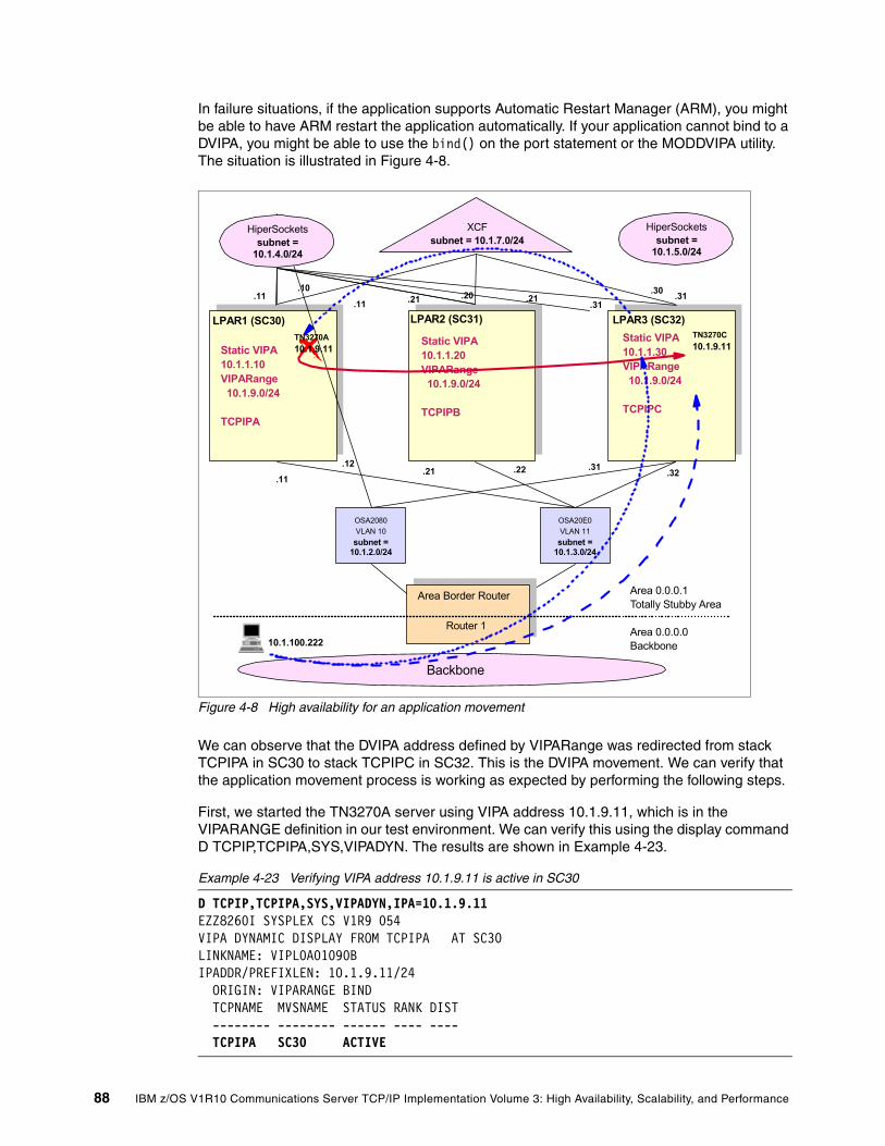
In failure situations, if the application supports Automatic Restart Manager (ARM), you might be able to have ARM restart the application automatically. If your application cannot bind to a DVIPA, you might be able to use the bind() on the port statement or the MODDVIPA utility. The situation is illustrated in Figure 4-8.
Figure 4-8 High availability for an application movement
We can observe that the DVIPA address defined by VIPARange was redirected from stack TCPIPA in SC30 to stack TCPIPC in SC32. This is the DVIPA movement. We can verify that the application movement process is working as expected by performing the following steps.
First, we started the TN3270A server using VIPA address 10.1.9.11, which is in the VIPARANGE definition in our test environment. We can verify this using the display command D TCPIP,TCPIPA,SYS,VIPADYN. The results are shown in Example 4-23.
Example 4-23 Verifying VIPA address 10.1.9.11 is active in SC30
D TCPIP,TCPIPA,SYS,VIPADYN,IPA=10.1.9.11 EZZ8260I SYSPLEX CS V1R9 054 VIPA DYNAMIC DISPLAY FROM TCPIPA AT SC30 LINKNAME: VIPL0A01090B IPADDR/PREFIXLEN: 10.1.9.11/24 ORIGIN: VIPARANGE BIND TCPNAME MVSNAME STATUS RANK DIST -------- -------- ------ ---- ---- TCPIPA SC30 ACTIVE
Static VIPA10.1.1.10VIPARange 10.1.9.0/24
TCPIPA
.11
.10
LPAR1 (SC30) LPAR2 (SC31) LPAR3 (SC32)
XCFsubnet = 10.1.7.0/24
HiperSocketssubnet =
10.1.5.0/24
.20 .30.11 .21 .31
.21 .31.12
.240
Static VIPA10.1.1.20VIPARange 10.1.9.0/24
TCPIPB
Static VIPA10.1.1.30VIPARange 10.1.9.0/24
TCPIPC
OSA20E0VLAN 11subnet =
10.1.3.0/24
OSA2080VLAN 10
subnet = 10.1.2.0/24
.22 .32
HiperSocketssubnet =
10.1.4.0/24
.11 .21 .31
Router 1
Backbone
Area 0.0.0.1 Totally Stubby Area
Area 0.0.0.0 Backbone
Area Border Router
TN3270A10.1.9.11
TN3270C10.1.9.11
10.1.100.222
88 IBM z/OS V1R10 Communications Server TCP/IP Implementation Volume 3: High Availability, Scalability, and Performance
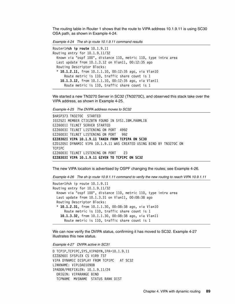
The routing table in Router 1 shows that the route to VIPA address 10.1.9.11 is using SC30 OSA path, as shown in Example 4-24.
Example 4-24 The sh ip route 10.1.9.11 command results
Router1#sh ip route 10.1.9.11Routing entry for 10.1.9.11/32 Known via "ospf 100", distance 110, metric 110, type intra area Last update from 10.1.3.12 on Vlan11, 00:12:35 ago Routing Descriptor Blocks: * 10.1.2.11, from 10.1.1.10, 00:12:35 ago, via Vlan10 Route metric is 110, traffic share count is 1 10.1.3.12, from 10.1.1.10, 00:12:35 ago, via Vlan11 Route metric is 110, traffic share count is 1
We started a new TN3270 Server in SC32 (TN3270C), and observed this stack take over the VIPA address, as shown in Example 4-25.
Example 4-25 The DVIPA address moves to SC32
$HASP373 TN3270C STARTED IEE252I MEMBER CTIEZBTN FOUND IN SYS1.IBM.PARMLIB EZZ6001I TELNET SERVER STARTED EZZ6003I TELNET LISTENING ON PORT 4992 EZZ6003I TELNET LISTENING ON PORT 992 EZZ8302I VIPA 10.1.9.11 TAKEN FROM TCPIPA ON SC30 EZD1205I DYNAMIC VIPA 10.1.9.11 WAS CREATED USING BIND BY TN3270C ON TCPIPC EZZ6003I TELNET LISTENING ON PORT 23 EZZ8303I VIPA 10.1.9.11 GIVEN TO TCPIPC ON SC32
The new VIPA location is advertised by OSPF changing the routes; see Example 4-26.
Example 4-26 The sh ip route 10.9.1.11 command to verify the new routing to reach VIPA 10.9.1.11
Router1#sh ip route 10.1.9.11Routing entry for 10.1.9.11/32 Known via "ospf 100", distance 110, metric 110, type intra area Last update from 10.1.3.31 on Vlan11, 00:08:38 ago Routing Descriptor Blocks: * 10.1.2.31, from 10.1.1.30, 00:08:38 ago, via Vlan10 Route metric is 110, traffic share count is 1 10.1.3.32, from 10.1.1.30, 00:08:38 ago, via Vlan11 Route metric is 110, traffic share count is 1
We can now verify the DVIPA status, confirming it has moved to SC32. Example 4-27 illustrates this new status.
Example 4-27 DVIPA active in SC31
D TCPIP,TCPIPC,SYS,VIPADYN,IPA=10.1.9.11 EZZ8260I SYSPLEX CS V1R9 737 VIPA DYNAMIC DISPLAY FROM TCPIPC AT SC32 LINKNAME: VIPL0A01090B IPADDR/PREFIXLEN: 10.1.9.11/24 ORIGIN: VIPARANGE BIND TCPNAME MVSNAME STATUS RANK DIST
Chapter 4. VIPA with dynamic routing 89

-------- -------- ------ ---- ---- TCPIPC SC32 ACTIVE TCPIPA SC30 MOVING 2 OF 2 RECORDS DISPLAYED
The active connections with TN3270A server in SC30 will continue to work and the traffic related to it will be sent through the new route and redirected to SC30 using the XCF connection. When a new TN3270 client connects using address 10.1.9.11, it will connect to TN3270C Server in SC32. This situation can be verified using the display command D TCPIP,TCPIPC,N,VCRT as seen in Example 4-28.
Example 4-28 D TCPIP,TCPIPC,N,VCRT
D TCPIP,TCPIPC,N,VCRT EZD0101I NETSTAT CS V1R9 TCPIPC 742 DYNAMIC VIPA CONNECTION ROUTING TABLE: DEST: 10.1.9.11..23 SOURCE: 10.1.100.222..2009 DESTXCF: 10.1.7.11 DEST: 10.1.9.11..23 SOURCE: 10.1.100.222..2012 DESTXCF: 10.1.7.31 2 OF 2 RECORDS DISPLAYED END OF THE REPORT
The existing sessions remain with SC30 until they end. At that time the DVIPA address for SC30 disappears.
90 IBM z/OS V1R10 Communications Server TCP/IP Implementation Volume 3: High Availability, Scalability, and Performance

4.3.3 Stack failure scenario using VIPADEFINE and VIPABACKUP
In this example, we lose the entire TCP/IP stack. (We simulate this by simply stopping the stack.) The failure situation is illustrated in Figure 4-9.
Figure 4-9 High availability for a stack failure
We used VIPADEFINE and VIPABACKUP definitions for the DVIPA to create a takeover and takeback environment. In our TCPIPA configuration, we created a VIPADEFINE with address 10.1.8.10, which is activated in SC30 as soon as the stack comes up. We also created, in the TCPIPC configuration, a VIPABACKUP for 10.1.8.10 with a rank of 4, stating this stack is a candidate to take over this address if something happens with the TCPIPA stack. We can verify this configuration is in place using command display tcpip,sys,vipadyn, as shown in Example 4-29.
Example 4-29 The d tcpip,tcpipa,vipadyn,ipa=10.1.8.10 command
D TCPIP,TCPIPA,SYS,VIPADYN,IPA=10.1.8.10 EZZ8260I SYSPLEX CS V1R9 845 VIPA DYNAMIC DISPLAY FROM TCPIPA AT SC30 LINKNAME: VIPL0A01080A IPADDR/PREFIXLEN: 10.1.8.10/24 ORIGIN: VIPADEFINE TCPNAME MVSNAME STATUS RANK DIST -------- -------- ------ ---- ---- TCPIPA SC30 ACTIVE
Static VIPA10.1.1.10VIPADefine 10.1.8.10/32VIPABackup 10.1.8.20/32 10.1.8.30/32
TCPIPA
.11
.10
LPAR1 (SC30) LPAR2 (SC31) LPAR3 (SC32)
XCFsubnet = 10.1.7.0/24
HiperSocketssubnet =
10.1.5.0/24
.20 .30.11 .21 .31
.21 .31.12
.240
Static VIPA10.1.1.20VIPADefine 10.1.8.20/24VIPABackup 10.1.8.10/32 10.1.8.30/32
TCPIPB
Static VIPA10.1.1.30VIPADefine 10.1.8.30/32VIPABackup 10.1.8.10/32 10.1.8.20/32
TCPIPC
OSA20E0VLAN 11subnet =
10.1.3.0/24
OSA2080VLAN 10
subnet = 10.1.2.0/24
.22 .32
HiperSocketssubnet =
10.1.4.0/24
.11 .21 .31
Router 1
Backbone
Area 0.0.0.1 Totally Stubby Area
Area 0.0.0.0 Backbone
Area Border Router
TN3270A
10.1.100.222
TN3270A
Chapter 4. VIPA with dynamic routing 91

TCPIPC SC32 BACKUP 004 2 OF 2 RECORDS DISPLAYED
We established a telnet session using address 10.1.8.10, then stopped the primary TCP/IP (in SC30) and observed the results; see Example 4-30.
Example 4-30 High availability in failure of the stack
P TCPIPA EZZ3205I SNMP SUBAGENT: SHUTDOWN IN PROGRESSEZZ0673I AUTOLOG TASK: SHUTDOWN IN PROGRESS EZZ6008I TELNET STOPPING EZZ8301I VIPA 10.1.8.10 TAKEN OVER FROM TCPIPA ON SC30 RO SC31,D TCPIP,TCPIPC,N,VIPADYN EZD0101I NETSTAT CS V1R9 TCPIPC 549 DYNAMIC VIPA: IPADDR/PREFIXLEN: 10.1.8.10/32 STATUS: ACTIVE ORIGIN: VIPABACKUP DISTSTAT:
This is a disruptive failure mode. Depending on the applications involved, clients might need to restart their sessions. (A subsequent takeback, when the TCP/IP stack in SC30 is restarted, is nondisruptive.)
When system SC32 discovers that SC30 has gone down (when SC30 leaves the XCF group), SC32 will take over the DVIPA address 10.1.8.10, advertising its new address through OSPF, as shown in Example 4-31.
Example 4-31 The sh ip route 10.1.8.10 in Router 1
Router1#sh ip route 10.1.8.10Routing entry for 10.1.8.10/32 Known via "ospf 100", distance 110, metric 110, type intra area Last update from 10.1.3.31 on Vlan11, 00:00:32 ago Routing Descriptor Blocks: * 10.1.2.31, from 10.1.1.30, 00:00:32 ago, via Vlan10 Route metric is 110, traffic share count is 1 10.1.3.32, from 10.1.1.30, 00:00:32 ago, via Vlan11 Route metric is 110, traffic share count is 1
After that we started new Telnet connections to the DVIPA address 10.1.8.10, which was now running on SC32. We used the NETSTAT operand N,VCRT to verify that these connections were going to DESTXCF 10.1.7.31 (the Dynamic XCF address of the SC32 stack) as shown in Example 4-32.
Example 4-32 New connections go to SC31
D TCPIP,TCPIPC,N,VCRT EZD0101I NETSTAT CS V1R9 TCPIPC 562 DYNAMIC VIPA CONNECTION ROUTING TABLE:DEST: 10.1.8.10..23 SOURCE: 10.1.100.222..1998 DESTXCF: 10.1.7.31 1 1 OF 1 RECORDS DISPLAYED END OF THE REPORT
1 DESTXCF 10.1.7.31 is the Dynamic XCF address of the SC32 stack.
92 IBM z/OS V1R10 Communications Server TCP/IP Implementation Volume 3: High Availability, Scalability, and Performance

Finally, we restarted the TCPIPA stack in SC30 and observed the takeback operation; see Example 4-33.
Example 4-33 Start TCPIPA in SC30 takeback function
S TCPIPA ... $HASP373 TCPIPA STARTED... EZB6473I TCP/IP STACK FUNCTIONS INITIALIZATION COMPLETE. EZAIN11I ALL TCPIP SERVICES FOR PROC TCPIPA ARE AVAILABLE. EZD1176I TCPIPA HAS SUCCESSFULLY JOINED THE TCP/IP SYSPLEX GROUP EZBTCPCS EZZ8302I VIPA 10.1.8.10 TAKEN FROM TCPIPC ON SC32 EZZ8303I VIPA 10.1.8.10 GIVEN TO TCPIPA ON SC30 EZD1214I INITIAL DYNAMIC VIPA PROCESSING HAS COMPLETED FOR TCPIPA
We verified that OSPF advertised that VIPA address 10.1.8.10 was back to SC30, displaying the route table in Router 1; see Example 4-34.
Example 4-34 The sh ip route 10.1.8.10
Router1#sh ip route 10.1.8.10Routing entry for 10.1.8.10/32 Known via "ospf 100", distance 110, metric 110, type intra area Last update from 10.1.3.11 on Vlan11, 00:12:34 ago Routing Descriptor Blocks: * 10.1.2.11, from 10.1.1.10, 00:12:34 ago, via Vlan10 Route metric is 110, traffic share count is 1 10.1.3.12, from 10.1.1.10, 00:12:34 ago, via Vlan11 Route metric is 110, traffic share count is 1
Finally, we started a new TN3270 session using the same address, and confirmed we connected the server located in SC30. We also confirmed our TN3270 session was still up as expected, using command D TCPIP,TCPIPA,N,VCRT; see Example 4-35.
Example 4-35 D TCPIP,TCPIPA,N,VCRT
RESPONSE=SC30 EZD0101I NETSTAT CS V1R9 TCPIPA 001 DYNAMIC VIPA CONNECTION ROUTING TABLE: DEST: 10.1.8.10..23 SOURCE: 10.1.100.222..2001 DESTXCF: 10.1.7.11 DEST: 10.1.8.10..23 SOURCE: 10.1.100.222..1998 DESTXCF: 10.1.7.31 2 OF 2 RECORDS DISPLAYED END OF THE REPORT
Chapter 4. VIPA with dynamic routing 93

94 IBM z/OS V1R10 Communications Server TCP/IP Implementation Volume 3: High Availability, Scalability, and Performance

Chapter 5. Internal application workload balancing
With internal application workload distribution, decisions for load balancing are made within the z/OS environment. Decisions can be based on:
� Application availability information received through Sysplex XCF communications� Real-time server capacity information from Workload Manager (WLM)� Quality of Service (QoS) data provided by the Service Policy Agent� A simple round-robin mechanism � Distribution method based on target weight using WEIGHTEDActive connections.
The application workload balancing decision maker provided with the Communications Server is the Sysplex Distributor (SD). Another option, the use of Shareport, is a method workload distribution done by the stack itself within a single z/OS system. This chapter describes internal application workload balancing, and primarily focuses on the Sysplex Distributor function and the benefits it provides. However, the use of Shareports is also explained.
This chapter discusses the following topics.
5
Section Topic
5.1, “Basic concepts of internal application workload balancing” on page 96
Basic concepts of internal application workload balancing
5.2, “Design and implementation examples” on page 119
Commonly implemented internal application workload balancing design scenarios, their dependencies, advantages, considerations, and recommendations
© Copyright IBM Corp. 2009. All rights reserved. 95

5.1 Basic concepts of internal application workload balancing
The design of the Sysplex Distributor provides an advisory mechanism that checks the availability of applications running on different z/OS servers in the same sysplex, and then selects the best-suited target server for a new connection request. The Sysplex Distributor bases its selections on real-time information from sources such as Workload Manager (WLM) and QoS data from the Service Policy Agent. Sysplex Distributor also measures the responsiveness of target servers in accepting new TCP connection setup requests, favoring those servers that are more successfully accepting new requests.
Internal workload balancing within the sysplex ensures that a group or cluster of application server instances can maintain optimum performance by serving client requests simultaneously. High availability considerations suggest at least two application server instances should exist, both providing the same services to their clients. If one application instance fails, the other carries on providing service. Multiple application instances minimize the number of users affected by the failure of a single application server instance. Thus, load balancing and availability are closely linked.
Figure 5-1 depicts, at a very high level, where the decision-maker for internal application workload balancing resides.
Figure 5-1 Decision point within the sysplex: internal workload balancing
The Sysplex Distributor is the internal decision-maker for application workload balancing. The Sysplex Distributor, together with XCF dynamics and dynamic VIPA, creates an advanced level of availability and workload balancing in a sysplex. Workload can be distributed to multiple server application instances without requiring changes to clients or networking hardware, and without delays in connection setup.
z/OS Communications Server allows you to implement a dynamic VIPA as a single network-visible IP address for a set of hosts that belong to the same sysplex cluster. A client
! Denotes decision point
z/OSLPAR
z/OSLPAR
OSA
INBOUND DATA PATH
OUTBOUND DATA PATH
INTERNAL - WORKLOAD BALANCING(Sysplex Distributor or Shareport)
SWITCH
! z/OSLPAR
96 IBM z/OS V1R10 Communications Server TCP/IP Implementation Volume 3: High Availability, Scalability, and Performance

located anywhere in the IP network can see the sysplex cluster as one IP address, regardless of the number of hosts that it includes.
For more background information describing the usage of Distributed DVIPA in a Sysplex Distributor environment including failover and recovery scenarios, refer to “Distributed DVIPA (Sysplex Distributor)” on page 20.
If you are planning to implement multitier optimized intra-sysplex workload balancing, you can refer to Chapter 7, “Intra-sysplex workload balancing” on page 201 for more information.
5.1.1 Sysplex Distributor—principles of operation
The Sysplex Distributor is a network-connected stack that owns a specific VIPA address and acts as the distributor for connection requests to the VIPA address. It is independent of network attachment technology, and works with both direct LAN connections (including OSA Express) and channel-attached router network connections.
All z/OS images involved communicate through XCF. This permits each TCP/IP stack to have full knowledge of IP addresses and server availability in all stacks. As mentioned earlier, the distribution of new connection requests can be based on real-time consultation with WLM (or round-robin), z/OS QoS Policy Agent, and the target stack for application availability.
When the selection of the target stack is done, the connection information is stored in the Sysplex Distributor stack to route future IP packets belonging to the same connection to the selected target stack. Routing is based on the connection (or session) to which IP packets belong, and this is known as connection-based routing. The hot standby stack is free to do other work, but takes over the ownership of the VIPA address and the distributor function if the primary stack leaves the XCF group (such as resulting from some sort of failure). This takeover is nondisruptive to all existing connections.
Chapter 5. Internal application workload balancing 97

Figure 5-2 provides a conceptual overview of Sysplex Distributor operation.
Figure 5-2 Sysplex Distributor for z/OS-integrated intra-sysplex workload balancing
5.1.2 Sysplex Distributor and Quality of Service policy
The use of internal application workload balancing and distribution is closely related to Quality of Service (QoS) objectives. The Policy Agent interacts with the Sysplex Distributor to assist with workload balancing. The ability to dynamically monitor server performance and affect sysplex workload distribution is an important part of the overall QoS mechanism.
The Policy Agent performs these distinct functions to assist the Sysplex Distributor:
� Policies can be defined to control which stacks the Sysplex Distributor can select. The definition of the outbound interface on the PolicyAction statement can limit the potential target stacks to a subset of those defined on the VIPADISTRIBUTE statement in the TCPIP.PROFILE. The stacks to which work is distributed can vary, for example, based on time periods in the policy. Another possibility is to limit the number of the Sysplex Distributor target stacks for inbound traffic from a given subnet. In this way, the total set of target stacks can be partitioned among different groups of users or applications requesting connections to distributed applications.
� The PolicyPerfMonitorForSDR statement in the pagent.conf file activates the Policy Agent QoS performance monitor function. When activated, the Policy Agent uses data about packet loss and timeouts that exceed defined thresholds and derives a QoS weight fraction for that target stack. This weight fraction is then used to reduce the WLM weight assigned to the target stacks, so that the Sysplex Distributor stack can use this information to better direct workload to where network traffic is best being handled. In this way, processor performance, server performance, and application network performance are taken into account when a decision is made for work distribution. This policy is activated on the Sysplex Distributor and the target stacks.
APPL
APPL
SYSPLEX DISTRIBUTOR
WLM
HOT STANDBY
VIPA1
HIDDENVIPA1
HIDDENVIPA1
z/OS SysplexPAGENT
INBOUND DATA PATH
OUTBOUND DATA PATH
SYSPLEX DISTRIBUTOR
98 IBM z/OS V1R10 Communications Server TCP/IP Implementation Volume 3: High Availability, Scalability, and Performance

� The Policy Agent at each target now collects information with an additional level of granularity, and the QoS performance data is collected for each service level that a target’s DVIPA port or application supports.
� The Policy Agent on the distributing stack drives the collection of this information by pulling it from the Policy Agents on the target stacks.
To exclude stale data from target stacks where the Policy Agent has terminated, the Policy Agent sends a heartbeat to the distributing stack at certain intervals. The distributing stack deletes QoS weight fraction data from a target stack when the heartbeat has not been received within a certain amount of time.
5.1.3 Portsharing
In order for a TCP server application to support a large number of client connections on a single system, it might be necessary to run more than one instance of the server application. (This assumes the application design allows this usage.) Portsharing is a method to distribute workload for IP applications within a z/OS LPAR. TCP/IP allows multiple listeners to listen on the same combination of port and interface. Workload destined for this application can be distributed among the group of servers that listen on the same port. Portsharing does not rely on an active Sysplex Distributor implementation; it works without SD. However, you can use portsharing in addition to SD operation.
z/OS currently supports two forms of portsharing:
� SHAREPORT
When specified on the PORT statement, incoming client connections for this port and interface are distributed by the TCP/IP stack across the listeners, using a weighted round-robin distribution method based on the servers’ Efficiency Fractions (SEFs) of the listeners sharing the port.
The SEF is a measure, calculated at intervals of approximately one minute, of the efficiency of the server application in accepting new connection requests and managing its backlog queue.
Figure 5-3 depicts a simple configuration where SHAREPORT is used for internal workload balancing.
Chapter 5. Internal application workload balancing 99

Figure 5-3 The TCP/IP stack is the decision-maker using a weighted round-robin method
� SHAREPORTWLM
The SHAREPORTWLM option can be used instead of SHAREPORT. Like SHAREPORT, SHAREPORTWLM causes incoming connections to be distributed among a set of TCP listeners. However, unlike SHAREPORT, the listener selection is based on WLM server-specific recommendations, modified by the SEF values for each listener. WLM server-specific recommendations are acquired at intervals of approximately one minute from WLM, and they reflect the listener’s capacity to handle additional work.
Figure 5-4 depicts a simple configuration where SHAREPORTWLM is used for internal workload balancing.
Figure 5-4 TCP/IP stack is the decision-maker using server-specific WLM data
OSA
INTERNAL - WORKLOAD BALANCING(using SHAREPORT on the PORT statement)
TCP 747
z/OS LPAR!
! Denotes decision point
APPL cAPPL bAPPL a
PORT 747 TCP APPLa SHAREPORT 747 TCP APPLb 747 TCP APPLc SWITCH
TCP 747
z/OS LPAR
OSA
INTERNAL - WORKLOAD BALANCING(using SHAREPORTWLM on the PORT statement)
!
! Denotes decision point
APPL cAPPL bAPPL a
PORT 747 TCP APPLa SHAREPORTWLM 747 TCP APPLb 747 TCP APPLc
WLM
SWITCH
100 IBM z/OS V1R10 Communications Server TCP/IP Implementation Volume 3: High Availability, Scalability, and

5.1.4 Optimized routing
Multiple instance applications, when running in a Sysplex Distributor Parallel Sysplex environment, cannot directly influence how many connections they will get or when they will get them. They rely on the Sysplex Distributor for those decisions. z/OS Communications Server uses optimized routing for the Sysplex Distributor and the DVIPA IP forwarding function so that the z/OS Communications Server can use any available IP network connectivity between TCP/IP stacks.
This function allows you to control the path to be taken to the target application server by using the new VIPAROUTE statement. The VIPAROUTE statement indicates which IP address on the target stack will be used as the destination IP address during route lookup selection. VIPAROUTE is used to select a route from a distribution stack to a target stack.
The first parameter of the VIPAROUTE statement specifies the Dynamic XCF address of the target stack. The second parameter specifies any fully qualified IP address in the HOME list of the target server (preferably a static VIPA address so that interface failures will not affect the availability of the target stack). An example of this usage is:
VIPADISTRIBUTE DEFINE 10.1.8.10 PORT 23 DESTIP ALLVIPAROUTE DEFINE 10.1.7.21 10.1.1.20
Optimal routes to target servers might be:
� IUTSAMEH, when the target server is within the same z/OS image� HiperSockets, when the target server is within the same CED� OSA-Express cards, when the target server is in another CEC
You are not required to use these specific routes, of course. Other considerations might dictate using (or not using) certain routes.
Figure 5-5 illustrates the use of DVIPA IP forwarding using OSA-Express adapters.
Figure 5-5 Intra-sysplex IP communication using OSA-Express instead of DynamicXCF
Tip: With this function, you can also use your dynamic XCF interfaces as backup routes, or preclude the use of dynamic XCF interfaces completely when routing DVIPA traffic.
OSA OSA OSAOSA
10.1.7.11 10.1.7.21
10.1.2.11 10.1.3.11 10.1.2.21 10.1.3.21
10.1.1.20
10.1.8.10 10.1.8.10
GRE DESTIP: 10.1.1.20
DESTIP: 10.1.8.10DESTIP: 10.1.8.10
DISTRIBUTOR TARGET
z/OS-1 z/OS-2
12
3DESTIP: 10.1.8.10
My z/OS Sysplex
Chapter 5. Internal application workload balancing 101

When a connection from the client is processed by Sysplex Distributor, it determines whether a matching VIPAROUTE statement has been specified. If it has, the best available route will be determined using the normal IP routing tables. If no matching VIPAROUTE statement exists for that target, the Sysplex Distributor uses Dynamic XCF interfaces.
When a VIPAROUTE statement is in effect, packets are sent from the distributor to the target encapsulated in a GRE wrapper. The outer IP header contains the VIPAROUTE target IP address as its destination IP address, and the distributor's dynamic XCF address as the source IP address.
RecommendationsWe make the following recommendations for using this function:
� Define a HiperSockets network in each CEC (through DEVICE/LINK definitions that interconnect all LPARs in that same CEC) and use a low routing cost for this network, so that it is the first-choice routing path.
� Define Gigabit Ethernet connectivity from all LPARs and use a low routing cost, but higher than used for the HiperSockets network, so that it is the second-choice routing path.
� Define the dynamic XCF network with a rather high routing cost so it will not be used for normal IP routing unless it is the only available interface (or define it as a non-OSPF interface so that it is not used for distributed DVIPA routing at all). That will save XCF communications for important sysplex data sharing traffic that must use it.
RestrictionsNote the following restrictions:
� Internal indicators, requested using the SO_CLUSTERCONNTYPE option of the GETSOCKOPT API and used to determine if the partner application is running in the same system or in the same sysplex, are no longer set if the destination IP address is a Dynamic VIPA or distributed Dynamic VIPA residing in the sysplex. The reason for this is that traffic destined to these IP addresses can now be forwarded to the target TCP/IP stacks over links or interfaces that are external to the sysplex.
� You must still configure the dynamic XCF address when using VIPAROUTE support because the Sysplex Distributor still uses dynamic XCF addresses to identify target TCP/IP stacks in the sysplex. In addition, there are several functions that continue to depend on dynamic XCF connectivity for intra-sysplex communications:
– Sysplex Wide Security Associations (SWSA) – Multi-Level Security (MLS) packets – Quality of Service (QoS) performance data collection of Policy Agent
5.1.5 Improved workload distribution
With z/OS, there is a sysplex distribution feature providing server-specific WLM recommendations for load balancing. The distribution of new connection requests can now be based on the actual workload of a target server. This method (SERVERWLM) indicates how well a specific server on a stack is meeting the goals of the WLM service class for the transactions that it is servicing (server-specific weights). This additional granularity enables the distributor to balance the workload more effectively.
Server-specific WLM recommendations can also be used by a stack to more evenly balance workload across a group of servers sharing the same port by specifying SHAREPORTWLM (instead of just SHAREPORT) on the PORT statement in the TCP/IP profile. When using this option, connections are distributed in a weighted round-robin fashion based on the WLM server-specific recommendations for the server.
102 IBM z/OS V1R10 Communications Server TCP/IP Implementation Volume 3: High Availability, Scalability, and

BASEWLM backgroundBASEWLM provides capacity recommendations in the form of weights for each system. WLM assigns a relative weight to each system in the sysplex, with the highest weight going to the system with the most available CPU capacity. The weights range between 0 and 64.
In the example illustrated in Figure 5-6, BASEWLM system weights of 50, 30, and 10 are returned by WLM for the targets for DVIPA1 port 8000. Then a QoS service level fraction is received from the target for each group of connections that map to a DVIPA/PORT for that service level. The QoS fraction percentage represents the performance of this group of connections, and is used to reduce the WLM weight.
Figure 5-6 BASEWLM distribution method using QoS data
The weights are then normalized (reduced proportionally), if necessary, to keep the number of successive connections directed to any given target small. For example, the weights for target 1, target 2, and target 3 are calculated as shown in Table 5-1.
Table 5-1 BASEWLM weight calculations
Continuing with our example, assume that 18 connection requests arrive for DVIPA1, port 8000. Based on the QoS-modified WLM weights for this DVIPA, port, and service level, then 7
Example WLM weights
Example QoS fractions
QoS-modified weights Normalized weights
Target 1 30 0% 30 = (30 - (30 * 0%)) 7
Target 2 50 20% 40 = (50 - (50 * 20%)) 10
Target 3 10 50% 5 = (10 - (10 * 50%)) 1
Note: The normalization algorithm used by the z/OS Communications Server is:
If any system weight provided by WLM is greater than 16, then all weights are normalized by dividing by 4 (and ignoring any remainder) after applying QoS fractions.
However, this approach might be changed in future releases of z/OS Communications Server.
WLM WEIGHTS
Target 1
DISTRIBUTOR
30
50
10
DVIPA1, 8000
7
10
1
TARGET 17
1020%
1
18CONNECTION
REQUESTS
QoS MOD. WLM WEIGHT
0
50%
QoS FRACTIONS
Target 1TARGET 2
Target 1TARGET 3
TARGET 1DVIPA1 PORT 8000
TARGET 2DVIPA1 PORT 8000
TARGET 3DVIPA1 PORT 8000
Chapter 5. Internal application workload balancing 103

connections are distributed to target 1, 10 connections are distributed to target 2, and 1 connection is distributed to target 3.
Note the following considerations for this process:
� The WLM weight is based on a comparison of the available capacity for new work on each system, not how well each server is meeting the goals of its service class.
� If all systems are using close to 100% of capacity, then the WLM weight is based on a comparison of displaceable capacity (the amount of lower importance work on each system). However, if the service class of the server is of low importance, then it might not be able to displace this work.
� If a target stack or a server on the target stack is not responsive, new connection requests continue to be routed to the target. The stack might appear lightly loaded because applications are not processing any new work.
� QoS fractions monitor target/client performance, but do not monitor the path to the target.
Server-specific WLMWLM can assign a weight based on how well the server is meeting the goal of its service class. The displaceable capacity for the new work is based on the importance of its service class. Figure 5-7 illustrates the server-specific WLM distribution method.
Figure 5-7 Server-specific WLM
In this example, a server-specific weight is received for each of the targets for DVIPA1, port 8000. The weights for target 1, target 2, and target 3 are calculated as shown in Table 5-2.
Table 5-2 Server-specific WLM weight calculation
Note: QoS fractions are only available if the Policy Agent is enabled on the Sysplex Distributor and all target systems and appropriate policies have been configured.
Server-specific weight x QOS fraction Normalized weight
Target 1 40 = (40 - (40 * 0%)) 10
Target 2 32 = (40 - (40 * 20%)) 8
Target 3 4 = (32 - (32 * 90%)) 1
DISTRIBUTOR
DVIPA1 PORT 8000
DVIPA1, 8000
19CONNECTION
REQUESTS 40
40
32
100
820%
190%
SERVER SPECIFIC WEIGHTS
QoS FRACTIONS
QoS MODIFIED WEIGHT
TARGET 1
DVIPA1 Port 8000
40
8
1
10
SERVER SPECIFIC WEIGHTS
TARGET 2
DVIPA1 Port 8000
40
TARGET 3
DVIPA1 Port 8000
32
TARGET 1
TARGET 2
TARGET 3
104 IBM z/OS V1R10 Communications Server TCP/IP Implementation Volume 3: High Availability, Scalability, and
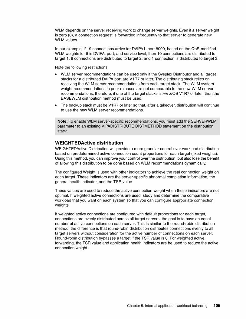
WLM depends on the server receiving work to change server weights. Even if a server weight is zero (0), a connection request is forwarded infrequently to that server to generate new WLM values.
In our example, if 19 connections arrive for DVIPA1, port 8000, based on the QoS-modified WLM weights for this DVIPA, port, and service level, then 10 connections are distributed to target 1, 8 connections are distributed to target 2, and 1 connection is distributed to target 3.
Note the following restrictions:
� WLM server recommendations can be used only if the Sysplex Distributor and all target stacks for a distributed DVIPA port are V1R7 or later. The distributing stack relies on receiving the WLM server recommendations from each target stack. The WLM system weight recommendations in prior releases are not comparable to the new WLM server recommendations; therefore, if one of the target stacks is not z/OS V1R7 or later, then the BASEWLM distribution method must be used.
� The backup stack must be V1R7 or later so that, after a takeover, distribution will continue to use the new WLM server recommendations.
WEIGHTEDActive distributionWEIGHTEDActive Distribution will provide a more granular control over workload distribution based on predetermined active connection count proportions for each target (fixed weights). Using this method, you can improve your control over the distribution, but also lose the benefit of allowing this distribution to be done based on WLM recommendations dynamically.
The configured Weight is used with other indicators to achieve the real connection weight on each target. These indicators are the server-specific abnormal completion information, the general health indicator, and the TSR value.
These values are used to reduce the active connection weight when these indicators are not optimal. If weighted active connections are used, study and determine the comparative workload that you want on each system so that you can configure appropriate connection weights.
If weighted active connections are configured with default proportions for each target, connections are evenly distributed across all target servers; the goal is to have an equal number of active connections on each server. This is similar to the round-robin distribution method; the difference is that round-robin distribution distributes connections evenly to all target servers without consideration for the active number of connections on each server. Round-robin distribution bypasses a target if the TSR value is 0. For weighted active forwarding, the TSR value and application health indicators are be used to reduce the active connection weight.
Note: To enable WLM server-specific recommendations, you must add the SERVERWLM parameter to an existing VIPADISTRIBUTE DISTMETHOD statement on the distribution stack.
Chapter 5. Internal application workload balancing 105

Figure 5-8 WEIGHTEDActive distribution
WEIGHTEDActive Distribution provides more granular control over workload distribution as shown in Figure 5-8:
� The comparative workload desired on each system must be understood so that appropriate connection weights can be configured (fixed weights). Looking at DVIPA2 Port 9000:
– 40% of the workload is configured to go to Target 1– 60% of the workload is configured to go to Target 2
� TSR values and Health Metrics (Abterms, Health) are applied to create a modified weight.
In the example the TSR of 50% results in a modified weight of 30 for Target 2. (Health Metrics are not shown in this example.)
� Active connection count goals are determined based on the modified connection weights and the active connections on each target (multiple of modified weight > active connections).
In the example, Target 2’s modified weight is 30. The connection goal is 60 (a multiple of 30 and greater than 58). Target 1’s weight must be 80 so that the proportions remain the same. New connection goals are determined when the active connection counts for all targets equals the connection goals
� The modified weights are normalized or reduced by dividing by 10.
� Distribution is still weighted round-robin based on the normalized weight, but a target is skipped if a connection goal is reached.
As 10 connection requests are received for DVIPA 1 port 8000, 6 are routed to Target 1 and 4 are routed to Target 2
As 7 connection requests are received for DVIPA 2 port 9000, only 2 requests (instead of 3) are routed to Target 2 because the connection goal of 60 is reached. So the other 5 connection requests are routed to Target 1.
2
5
D VIPA1, Port 8000
10 C onnectionR equests
D V IPA2, Port 9000
4
6
Serve r S ta tsServe r S ta tsServer S ta ts Abterm s H ea lth
7 C onnectionR equests
D istribu tor
D VIPA1 Port 8000
D V IPA2 Port 9000
Target 1
Target 2
Target 1
Target 2
TSR M od N ormC onnG oal ActiveC onns
60 100 60 6 60 12 18
8 124 4040 100 40
40
60
100
50
40
30
4
3 60
80 70
58
75
60
Target 1D VIPA1 Port 8000 D V IPA2 Port 9000
Target 2D VIPA1 Port 8000 D V IPA2 Port 9000
106 IBM z/OS V1R10 Communications Server TCP/IP Implementation Volume 3: High Availability, Scalability, and

The use of weighted active connections (WEIGHTEDActive) are recommended in the following cases:
� Application scaling concerns
Target systems vary significantly in terms of capacity (small systems and larger systems). WLM recommendations might favor the larger systems significantly. However, a target application might not scale well to larger systems; because of its design, it might not be able to take full advantage of the additional CPU capacity on the larger systems. This can result in these types of servers getting inflated WLM recommendations when running on larger systems, and getting overloaded with work.
� Unequal number of SHAREPORT servers
If SHAREPORT is being used, but not all systems have the same number of SHAREPORT server instances (for example, one system has two instances and the other has three). The current round-robin or WLM recommendations do not change distribution based on the number of server instances on each target. Round-robin distribution distributes one connection per target stack regardless of the number of SHAREPORT server instances on that stack. WLM server-specific weights from a target stack with multiple server instances reflect the average weight.
� You need to control the amount of capacity that specific workloads can consume on each system.
For example, you might need to reserve some capacity on certain systems for batch workloads that are added into selected systems during specific time periods and have specific time window completion requirements. If those systems are also a target for long-running distributed DVIPA connections, WLM recommendations allow that available capacity to be consumed. This can potentially impact the completion times of the batch jobs when they begin to run, if they are not able to displace the existing non-batch workloads. Similarly, the existing connections on that system can experience performance problems if the batch jobs displace those workloads.
WLM routing service enhancements for zAAP and zIIPThe System z platform recently introduced specialty processors that can be deployed and exploited by qualified workloads on z/OS. This includes support for the following processors:
� System z Application Assist Processor (zAAP)
These processors can be used for Java™ application workloads on z/OS (including workloads running under z/OS WebSphere Application Server).
� System z Integrated Information Processor (zIIP)
These processors can be used by qualified z/OS DB2-related workloads and IPSec processing.
When the Sysplex Distributor routes incoming connections based on Workload Manager (WLM) system weights, it will consider available zAAP CPU capacity, available zIIP CPU capacity, or both. In this case, Sysplex Distributor uses a composite WLM weight based on the available capacity of each processor type and the current use of each processor type by this application.
The WLM workload information is based on a comparison of available general CPU capacity for each target system. If the application uses System z Application Assist Processor (zAAP) capacity or System z9® Integrated Information Processor (zIIP) capacity, you can configure the VIPADISTRIBUTE statement so that available zAAP CPU capacity and zIIP CPU capacity are also considered.
Chapter 5. Internal application workload balancing 107

If you need to consider zAAP and zIIP CPU capacity, evaluate whether you can use SERVERWLM distribution as an alternative to BASEWLM distribution for this application:
� SERVERWLM distribution has the advantage that processor proportions are automatically determined and dynamically updated by WLM based on the actual CPU usage of the application.
� BASEWLM distribution for the processor proportions is determined by studying the workload usage of the assist processors (zAAPs and zIIPs). This can be done by analyzing SMF records and using performance monitors reports such as RMF.
Setting up these functionsThis section shows you how to set up the SERVERWLM, BASEWLM, and SHAREPORT functions.
SERVERWLMEnable the Sysplex Distributor to consider zIIP or zAAP processor capacity for target servers. Example 5-1 shows an extract of the profile TCT/IP.
Example 5-1 TCP/IP definition for SERVERWLM
VIPADYNAMIC VIPADEFine MOVEable IMMEDiate 255.255.255.0 10.1.8.30 VIPADISTribute DISTMethod SERVERWLM 10.1.8.30 PORT 23 DESTIP 10.1.7.31 10.1.7.21 10.1.7.11
Example 5-2 shows the output of the D TCPIP,TCPIPC,N,VIPADCFG,DETAIL command.
Example 5-2 Output of NETSTAT VIPADCFG command
EZD0101I NETSTAT CS V1R10 TCPIPC 662DYNAMIC VIPA INFORMATION: VIPA DISTRIBUTE: DEST: 10.1.8.30..23 DESTXCF: 10.1.7.31 SYSPT: NO TIMAFF: NO FLG: SERVERWLM OPTLOC: NO DEST: 10.1.8.30..23 DESTXCF: 10.1.7.21 SYSPT: NO TIMAFF: NO FLG: SERVERWLM OPTLOC: NO
Restriction: These new composite weights will only be returned by WLM if all systems in the sysplex are V1R9 or later, regardless of whether the systems participate in workload distribution or if systems are members of different subplexes.
In a mixed release environment, general CP weights only are used to determine the WLM System or server-specific weight because there is no information available about zAAP and zIIP capacity from the older releases.
DNS/WLM does not exploit the new zAAP and zIIP processors. WLM recommendations continue to consider only general CPU capacity.
LBA considers zAAP and zIIP weight recommendations for server members, but not system members. WLM recommendations for system members continues to consider only general CPU capacity.
108 IBM z/OS V1R10 Communications Server TCP/IP Implementation Volume 3: High Availability, Scalability, and

DEST: 10.1.8.30..23 DESTXCF: 10.1.7.11 SYSPT: NO TIMAFF: NO FLG: SERVERWLM OPTLOC: NO
Example 5-3 shows the output of the D TCPIP,TCPIPC,N,VDPT,DETAIL command.
Example 5-3 Output of NETSTAT VDPT (SERVERWLM) command
EZD0101I NETSTAT CS V1R10 TCPIPC 667 DYNAMIC VIPA DESTINATION PORT TABLE:DEST: 10.1.8.30..23 DESTXCF: 10.1.7.11 TOTALCONN: 0000000000 RDY: 001 WLM: 16 TSR: 100 FLG: SERVERWLM TCSR: 100 CER: 100 SEF: 100 WEIGHT: 64 RAW CP: 64 ZAAP: 00 ZIIP: 00 PROPORTIONAL CP: 64 ZAAP: 00 ZIIP: 00 ABNORM: 0000 HEALTH: 100 ACTCONN: 0000000000 QOSPLCACT: *DEFAULT* W/Q: 16 DEST: 10.1.8.30..23 DESTXCF: 10.1.7.21 TOTALCONN: 0000000000 RDY: 001 WLM: 16 TSR: 100 FLG: SERVERWLM TCSR: 100 CER: 100 SEF: 100 WEIGHT: 64 RAW CP: 64 ZAAP: 00 ZIIP: 00 PROPORTIONAL CP: 64 ZAAP: 00 ZIIP: 00 ABNORM: 0000 HEALTH: 100 ACTCONN: 0000000000 QOSPLCACT: *DEFAULT* W/Q: 16 DEST: 10.1.8.30..23 DESTXCF: 10.1.7.31 TOTALCONN: 0000000000 RDY: 001 WLM: 16 TSR: 100 FLG: SERVERWLM TCSR: 100 CER: 100 SEF: 100 WEIGHT: 64 RAW CP: 64 ZAAP: 00 ZIIP: 00 PROPORTIONAL CP: 64 ZAAP: 00 ZIIP: 00 ABNORM: 0000 HEALTH: 100 ACTCONN: 0000000000 QOSPLCACT: *DEFAULT* W/Q: 16
In this case we are using CP only; there is no application using zAAP or zIIP processor.
For more information about the NETSTAT command, refer to IP System Administrator’s Commands, SC31-8781.
Chapter 5. Internal application workload balancing 109

BASEWLMEnable the Sysplex Distributor to consider zIIP or zAAP processor capacity for target servers. Example 5-4 shows an extract of the profile TCT/IP.
Example 5-4 TCP/IP definition for BASEWLM
VIPADYNAMIC VIPADEFine MOVEable IMMEDiate 255.255.255.0 10.1.8.30 VIPADISTribute DISTMethod BASEWLM PROCTYPE CP 20 ZAAP 40 ZIIP 40 10.1.8.30 PORT 20 21 DESTIP ALL VIPADISTribute DISTMethod BASEWLM PROCTYPE CP 20 ZAAP 40 ZIIP 40 10.1.8.30 PORT 28538 28518 28510 28502 28503 DESTIP 10.1.7.31 10.1.7.21 10.1.7.11
The PROCTYPE parameter is used in conjunction with BASEWLM and sets the weight for each kind of processor.
Example 5-5 shows the output of the D TCPIP,TCPIPC,N,VIPADCFG,DETAIL command.
Example 5-5 Output of NETSTAT VIPADCFG (BASEWLM) command
EZD0101I NETSTAT CS V1R10 TCPIPC 721DYNAMIC VIPA INFORMATION: VIPA DISTRIBUTE: DEST: 10.1.8.30..20 DESTXCF: ALL SYSPT: NO TIMAFF: NO FLG: BASEWLM OPTLOC: NO PROCTYPE: CP: 20 ZAAP: 40 ZIIP: 40 DEST: 10.1.8.30..21 DESTXCF: ALL SYSPT: NO TIMAFF: NO FLG: BASEWLM OPTLOC: NO PROCTYPE: CP: 20 ZAAP: 40 ZIIP: 40 DEST: 10.1.8.30..28502 DESTXCF: 10.1.7.21 SYSPT: NO TIMAFF: NO FLG: BASEWLM OPTLOC: NO PROCTYPE: CP: 20 ZAAP: 40 ZIIP: 40 DEST: 10.1.8.30..28502 DESTXCF: 10.1.7.11 SYSPT: NO TIMAFF: NO FLG: BASEWLM OPTLOC: NO PROCTYPE: CP: 20 ZAAP: 40 ZIIP: 40 DEST: 10.1.8.30..28503 DESTXCF: 10.1.7.31 SYSPT: NO TIMAFF: NO FLG: BASEWLM OPTLOC: NO PROCTYPE:
110 IBM z/OS V1R10 Communications Server TCP/IP Implementation Volume 3: High Availability, Scalability, and

CP: 20 ZAAP: 40 ZIIP: 40 DEST: 10.1.8.30..28503 DESTXCF: 10.1.7.21 SYSPT: NO TIMAFF: NO FLG: BASEWLM OPTLOC: NO PROCTYPE: CP: 20 ZAAP: 40 ZIIP: 40 DEST: 10.1.8.30..28503 DESTXCF: 10.1.7.11 SYSPT: NO TIMAFF: NO FLG: BASEWLM OPTLOC: NO PROCTYPE: CP: 20 ZAAP: 40 ZIIP: 40 DEST: 10.1.8.30..28510 DESTXCF: 10.1.7.31 SYSPT: NO TIMAFF: NO FLG: BASEWLM OPTLOC: NO PROCTYPE: CP: 20 ZAAP: 40 ZIIP: 40 DEST: 10.1.8.30..28510 DESTXCF: 10.1.7.21 SYSPT: NO TIMAFF: NO FLG: BASEWLM OPTLOC: NO PROCTYPE: CP: 20 ZAAP: 40 ZIIP: 40 DEST: 10.1.8.30..28510 DESTXCF: 10.1.7.11 SYSPT: NO TIMAFF: NO FLG: BASEWLM OPTLOC: NO PROCTYPE: CP: 20 ZAAP: 40 ZIIP: 40 DEST: 10.1.8.30..28518 DESTXCF: 10.1.7.31 SYSPT: NO TIMAFF: NO FLG: BASEWLM OPTLOC: NO PROCTYPE: CP: 20 ZAAP: 40 ZIIP: 40 DEST: 10.1.8.30..28518 DESTXCF: 10.1.7.21 SYSPT: NO TIMAFF: NO FLG: BASEWLM OPTLOC: NO PROCTYPE: CP: 20 ZAAP: 40 ZIIP: 40 DEST: 10.1.8.30..28518 DESTXCF: 10.1.7.11 SYSPT: NO TIMAFF: NO FLG: BASEWLM OPTLOC: NO PROCTYPE: CP: 20 ZAAP: 40 ZIIP: 40 DEST: 10.1.8.30..28538 DESTXCF: 10.1.7.31 SYSPT: NO TIMAFF: NO FLG: BASEWLM OPTLOC: NO PROCTYPE: CP: 20 ZAAP: 40 ZIIP: 40
Chapter 5. Internal application workload balancing 111

DEST: 10.1.8.30..28538 DESTXCF: 10.1.7.21 SYSPT: NO TIMAFF: NO FLG: BASEWLM OPTLOC: NO PROCTYPE: CP: 20 ZAAP: 40 ZIIP: 40 DEST: 10.1.8.30..28538 DESTXCF: 10.1.7.11 SYSPT: NO TIMAFF: NO FLG: BASEWLM OPTLOC: NO PROCTYPE: CP: 20 ZAAP: 40 ZIIP: 40 VIPA ROUTE: DESTXCF: 10.1.7.11 TARGETIP: 10.1.1.10 DESTXCF: 10.1.7.21 TARGETIP: 10.1.1.20 DESTXCF: 10.1.7.31 TARGETIP: 10.1.1.30
Example 5-6 shows the output of the D TCPIP,TCPIPC,N,VDPT,DETAIL command.
Example 5-6 Output of NETSTAT VDPT (BASEWLM) command
EZD0101I NETSTAT CS V1R10 TCPIPC 737 DYNAMIC VIPA DESTINATION PORT TABLE:DEST: 10.1.8.30..20 DESTXCF: 10.1.7.41 TOTALCONN: 0000000000 RDY: 000 WLM: 01 TSR: 100 FLG: BASEWLM TCSR: 100 CER: 100 SEF: 100 WEIGHT: 01 RAW CP: 08 ZAAP: 00 ZIIP: 00 PROPORTIONAL CP: 01 ZAAP: 00 ZIIP: 00 ACTCONN: 0000000000 QOSPLCACT: *DEFAULT* W/Q: 01 DEST: 10.1.8.30..21 DESTXCF: 10.1.7.11 TOTALCONN: 0000000000 RDY: 001 WLM: 01 TSR: 100 FLG: BASEWLM TCSR: 100 CER: 100 SEF: 100 WEIGHT: 01 RAW CP: 08 ZAAP: 00 ZIIP: 00 PROPORTIONAL CP: 01 ZAAP: 00 ZIIP: 00 ACTCONN: 0000000000 QOSPLCACT: *DEFAULT* W/Q: 01 DEST: 10.1.8.30..21 DESTXCF: 10.1.7.31 TOTALCONN: 0000000000 RDY: 001 WLM: 01 TSR: 100 FLG: BASEWLM TCSR: 100 CER: 100 SEF: 100 WEIGHT: 01 RAW CP: 08 ZAAP: 00 ZIIP: 00 PROPORTIONAL CP: 01 ZAAP: 00 ZIIP: 00
112 IBM z/OS V1R10 Communications Server TCP/IP Implementation Volume 3: High Availability, Scalability, and

ACTCONN: 0000000000 QOSPLCACT: *DEFAULT* W/Q: 01 DEST: 10.1.8.30..21 DESTXCF: 10.1.7.41 TOTALCONN: 0000000000 RDY: 001 WLM: 01 TSR: 100 FLG: BASEWLM TCSR: 100 CER: 100 SEF: 100 WEIGHT: 01 RAW CP: 08 ZAAP: 00 ZIIP: 00 PROPORTIONAL CP: 01 ZAAP: 00 ZIIP: 00 ACTCONN: 0000000000 QOSPLCACT: *DEFAULT* W/Q: 01 DEST: 10.1.8.30..28502 DESTXCF: 10.1.7.11 TOTALCONN: 0000000000 RDY: 000 WLM: 01 TSR: 100 FLG: BASEWLM TCSR: 100 CER: 100 SEF: 100 WEIGHT: 01 RAW CP: 08 ZAAP: 00 ZIIP: 00 PROPORTIONAL CP: 01 ZAAP: 00 ZIIP: 00 ACTCONN: 0000000000 QOSPLCACT: *DEFAULT* W/Q: 01 DEST: 10.1.8.30..28502 DESTXCF: 10.1.7.31 TOTALCONN: 0000000000 RDY: 000 WLM: 01 TSR: 100 FLG: BASEWLM TCSR: 100 CER: 100 SEF: 100 WEIGHT: 01 RAW CP: 08 ZAAP: 00 ZIIP: 00 PROPORTIONAL CP: 01 ZAAP: 00 ZIIP: 00 ACTCONN: 0000000000 QOSPLCACT: *DEFAULT* W/Q: 01 DEST: 10.1.8.30..28503 DESTXCF: 10.1.7.11 TOTALCONN: 0000000000 RDY: 000 WLM: 01 TSR: 100 FLG: BASEWLM TCSR: 100 CER: 100 SEF: 100 WEIGHT: 01 RAW CP: 08 ZAAP: 00 ZIIP: 00 PROPORTIONAL CP: 01 ZAAP: 00 ZIIP: 00 ACTCONN: 0000000000 QOSPLCACT: *DEFAULT* W/Q: 01 DEST: 10.1.8.30..28503 DESTXCF: 10.1.7.31 TOTALCONN: 0000000000 RDY: 000 WLM: 01 TSR: 100 FLG: BASEWLM TCSR: 100 CER: 100 SEF: 100 WEIGHT: 01 RAW CP: 08 ZAAP: 00 ZIIP: 00 PROPORTIONAL CP: 01 ZAAP: 00 ZIIP: 00
Chapter 5. Internal application workload balancing 113

ACTCONN: 0000000000 QOSPLCACT: *DEFAULT* W/Q: 01 DEST: 10.1.8.30..28510 DESTXCF: 10.1.7.11 TOTALCONN: 0000000000 RDY: 000 WLM: 01 TSR: 100 FLG: BASEWLM TCSR: 100 CER: 100 SEF: 100 WEIGHT: 01 RAW CP: 08 ZAAP: 00 ZIIP: 00 PROPORTIONAL CP: 01 ZAAP: 00 ZIIP: 00 ACTCONN: 0000000000 QOSPLCACT: *DEFAULT* W/Q: 01 DEST: 10.1.8.30..28510 DESTXCF: 10.1.7.31 TOTALCONN: 0000000000 RDY: 000 WLM: 01 TSR: 100 FLG: BASEWLM TCSR: 100 CER: 100 SEF: 100 WEIGHT: 01 RAW CP: 08 ZAAP: 00 ZIIP: 00 PROPORTIONAL CP: 01 ZAAP: 00 ZIIP: 00 ACTCONN: 0000000000 QOSPLCACT: *DEFAULT* W/Q: 01 DEST: 10.1.8.30..28518 DESTXCF: 10.1.7.11 TOTALCONN: 0000000000 RDY: 000 WLM: 01 TSR: 100 FLG: BASEWLM TCSR: 100 CER: 100 SEF: 100 WEIGHT: 01 RAW CP: 08 ZAAP: 00 ZIIP: 00 PROPORTIONAL CP: 01 ZAAP: 00 ZIIP: 00 ACTCONN: 0000000000 QOSPLCACT: *DEFAULT* W/Q: 01 DEST: 10.1.8.30..28518 DESTXCF: 10.1.7.31 TOTALCONN: 0000000000 RDY: 000 WLM: 01 TSR: 100 FLG: BASEWLM TCSR: 100 CER: 100 SEF: 100 WEIGHT: 01 RAW CP: 08 ZAAP: 00 ZIIP: 00 PROPORTIONAL CP: 01 ZAAP: 00 ZIIP: 00 ACTCONN: 0000000000 QOSPLCACT: *DEFAULT* W/Q: 01 DEST: 10.1.8.30..28538 DESTXCF: 10.1.7.11 TOTALCONN: 0000000000 RDY: 000 WLM: 01 TSR: 100 FLG: BASEWLM TCSR: 100 CER: 100 SEF: 100 WEIGHT: 01 RAW CP: 08 ZAAP: 00 ZIIP: 00 PROPORTIONAL CP: 01 ZAAP: 00 ZIIP: 00
114 IBM z/OS V1R10 Communications Server TCP/IP Implementation Volume 3: High Availability, Scalability, and
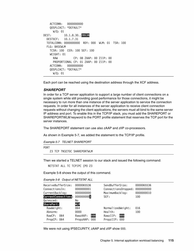
ACTCONN: 0000000000 QOSPLCACT: *DEFAULT* W/Q: 01 DEST: 10.1.8.30..28538 DESTXCF: 10.1.7.31 TOTALCONN: 0000000000 RDY: 000 WLM: 01 TSR: 100 FLG: BASEWLM TCSR: 100 CER: 100 SEF: 100 WEIGHT: 01 RAW CP: 08 ZAAP: 00 ZIIP: 00 PROPORTIONAL CP: 01 ZAAP: 00 ZIIP: 00 ACTCONN: 0000000000 QOSPLCACT: *DEFAULT* W/Q: 01
Each port can be reached using the destination address through the XCF address.
SHAREPORTIn order for a TCP server application to support a large number of client connections on a single system while still providing good performance for those connections, it might be necessary to run more than one instance of the server application to service the connection requests. In order for all instances of the server application to receive client connection requests without changing the client applications, the servers must all bind to the same server IP address and port. To enable this in the TCP/IP stack, you must add the SHAREPORT or SHAREPORTWLM keyword to the PORT profile statement that reserves the TCP port for the server instances.
The SHAREPORT statement can use also zAAP and zIIP co-processors.
As shown in Example 5-7, we added the statement to the TCP/IP profile.
Example 5-7 TELNET SHAREPORT
PORT 23 TCP TN3270C SHAREPORTWLM
Then we started a TELNET session to our stack and issued the following command:
NETSTAT ALL TC TCPIPC (PO 23
Example 5-8 shows the output of this command.
Example 5-8 Output of NETSTAT ALL
ReceiveBufferSize: 0000065536 SendBufferSize: 0000065536ConnectionsIn: 0000000001 ConnectionsDropped: 0000000000CurrentBacklog: 0000000000 MaximumBacklog: 0000000010CurrentConnections: 0000000001 SEF: 100 Quiesced: No SharePort: WLM RawWeight: 064 NormalizedWeight: 016 Abnorm: 0000 Health: 100 RawCP: 064 RawzAAP: 000 RawzIIP: 000 PropCP: 064 PropzAAP: 000 PropzIIP: 000
We were not using IPSECURITY; zAAP and zIIP show 000.
Chapter 5. Internal application workload balancing 115
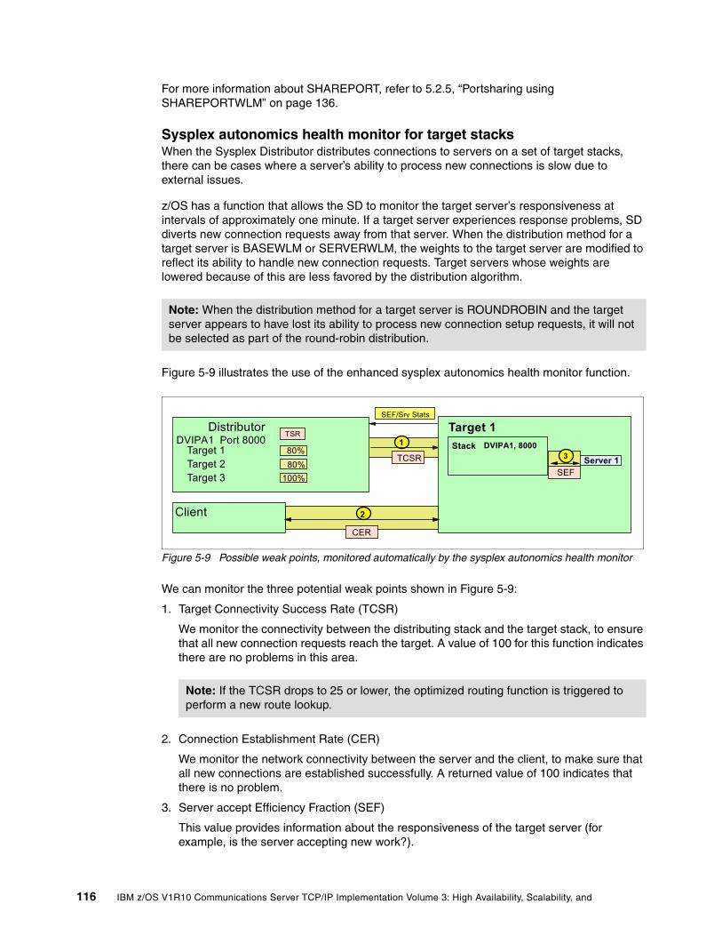
For more information about SHAREPORT, refer to 5.2.5, “Portsharing using SHAREPORTWLM” on page 136.
Sysplex autonomics health monitor for target stacksWhen the Sysplex Distributor distributes connections to servers on a set of target stacks, there can be cases where a server’s ability to process new connections is slow due to external issues.
z/OS has a function that allows the SD to monitor the target server’s responsiveness at intervals of approximately one minute. If a target server experiences response problems, SD diverts new connection requests away from that server. When the distribution method for a target server is BASEWLM or SERVERWLM, the weights to the target server are modified to reflect its ability to handle new connection requests. Target servers whose weights are lowered because of this are less favored by the distribution algorithm.
Figure 5-9 illustrates the use of the enhanced sysplex autonomics health monitor function.
Figure 5-9 Possible weak points, monitored automatically by the sysplex autonomics health monitor
We can monitor the three potential weak points shown in Figure 5-9:
1. Target Connectivity Success Rate (TCSR)
We monitor the connectivity between the distributing stack and the target stack, to ensure that all new connection requests reach the target. A value of 100 for this function indicates there are no problems in this area.
2. Connection Establishment Rate (CER)
We monitor the network connectivity between the server and the client, to make sure that all new connections are established successfully. A returned value of 100 indicates that there is no problem.
3. Server accept Efficiency Fraction (SEF)
This value provides information about the responsiveness of the target server (for example, is the server accepting new work?).
Note: When the distribution method for a target server is ROUNDROBIN and the target server appears to have lost its ability to process new connection setup requests, it will not be selected as part of the round-robin distribution.
Note: If the TCSR drops to 25 or lower, the optimized routing function is triggered to perform a new route lookup.
1
Server 1
Client
Target 1Stack DVIPA1, 8000
DistributorDVIPA1 Port 8000
Target 2Target 1
Target 3
SEF/Srv Stats
80%100%
TSR
80%TCSR
CER
SEF
2
3
116 IBM z/OS V1R10 Communications Server TCP/IP Implementation Volume 3: High Availability, Scalability, and

All these values are sent to the distributor. The SD then creates a Target Server Responsiveness fraction (TSR). This, in turn, influences the decisions made by the Sysplex Distributor. The higher the value, the healthier the condition of the target server.
Figure 5-10 illustrates the influence of the sysplex autonomics health monitor based on the sample we used for server-specific WLM.
Figure 5-10 Sysplex autonomics health monitor for target stacks
Table 5-3 lists the server-specific WLM weight calculation with autonomics for each target.
Table 5-3 Server-specific WLM weight calculation with autonomics
The weight for each target server is calculated as follows:
1. The QoS service level is applied against the raw WLM server weight.
2. The TSR fraction is calculated from the SEF value and server statistics that are received from the target and from information that the distributor keeps for each server. If the QoS modified WLM weight is 32 and the TSR fraction is 80%, the new modified weight is 25 (32 * 80%).
3. The weights are normalized. The normalization algorithm is:
If any server-specific WLM weight is greater than 16, then all weights are normalized after applying QoS and TSR fractions and dividing by 4 (ignoring any remainder).
WLM weight x QoS fraction Normalized weight
Target 1 36 = (40 - (40 * 0%))*90% 9
Target 2 25 = (40 - (40 * 20%))*80% 6
Target 3 16 = (32 - (32 * 50%))*100% 4
Target 2
Target 3
Distributor
DVIPA1 Port 8000
Target 1 40
Target 2Target 3
90
620%
450%
Server-specific weights QoS norm. Weight
Target 3
Target 1DVIPA1 Port 8000
DVIPA1 Port 8000
DVIPA1 Port 8000
100%
90%
80%
TSR
Server SEF
Server SEF
Server SEF
QoS fractions
Server Sp. Wts
SEF / Srvstats
40
32
40
40
32
90%
80%
100%
Chapter 5. Internal application workload balancing 117

5.1.6 Unreachable DVIPA Detection and Recovery
Sysplex autonomics have been enhanced to enable you to specify key network interfaces that should be monitored by the TCP/IP stacks. You can monitor interfaces to ensure that they are functioning and that dynamic routes are known over these interfaces, as shown in Figure 5-11. If a failure occurs on all specified interfaces, sysplex autonomics will trigger other TCP/IP stacks in the sysplex to take over responsibilities for the DVIPAs. This function can be very useful for TCP/IP stacks that own and advertise DVIPAs, and also for TCP/IP stacks that act as backup owners for these DVIPAs.
Figure 5-11 Sysplex Autonomics detection of unreachable DVIPA
The SYSPLEMONITOR statement and the LINK statement include parameters which are explained here:
� MONINTERFACE
Request the TCP/IP stack to monitor the status of specified interfaces. The interfaces being monitored are those that are configured with the MONSYSPLEX parameter on the LINK statement.
� NOMONINTERFACE
Request the TCP/IP stack to not monitor the status of any interface. This is the default.
� DYNROUTE
Request the TCP/IP stack to monitor the presence of dynamic routes over monitored interfaces. This level of monitoring is useful in detecting problems that OMPROUTE is having in communicating with other routing daemons on the selected interfaces. If no dynamic routes are present in the TCP/IP stack, even though the monitored interface is active, this provides an indicator that client requests will not be able to reach this TCP/IP stack over that interface. This is the default when MONINTERFACE is configured.
Router #1
OSA
SD
A. Is the monitered interface up?B. Is OMPROUTE receiving route information over that monitored interface from Router#1?
OMPROUTE(OSPF/RIP)
: monitored interface
A
B
118 IBM z/OS V1R10 Communications Server TCP/IP Implementation Volume 3: High Availability, Scalability, and

� NODYNROUTE
Request the TCP/IP stack not to monitor the presence of dynamic routes over the monitored interfaces. This is the default when the MONINTERFACE parameter is not configured.
� MONSYSPLEX
This indicates that the status of this link is monitored by the sysplex autonomics. This parameter is not in effect unless the MONINTERFACE parameter is coded on the GLOBALCONFIG SYSPLEXMONITOR profile statement. This parameter is dynamically modifiable.
� NOMONSYSPLEX
This indicates that the status of this link is not monitored by sysplex autonomics. This is the default and is dynamically modifiable.
� TIMERSECS
The TIMERSECS value which is specified on the GLOBAL CONFIG SYSPLEXMONITOR statement is used to determine how quickly sysplex autonomics will react when a problem is detected. The default value is 60 seconds.
For configuration and verification examples, refer to 5.2.6, “Sysplex Distributor using Unreachable DVIPA Detection and Recovery” on page 142.
5.2 Design and implementation examples
This section contains the following scenarios, which demonstrate Sysplex Distributor usage:
� Sysplex Distributor using server-specific WLM� Sysplex Distributor using BASEWLM� Sysplex Distributor using round-robin� Sysplex Distributor using WEIGHTEDActive method� Portsharing using SHAREPORTWLM� Sysplex Distributor using Unreachable DVIPA Detection and Recovery
5.2.1 Sysplex Distributor using server-specific WLM
Server-specific Workload Manager (WLM) controls for load balancing is a sysplex distribution feature in z/OS. The key PROFILE statements are shown in Example 5-9.
Example 5-9 Using ServerWLM distributed method
VIPADynamic VIPADEFine MOVEable IMMEDiate 255.255.255.0 10.1.8.10 VIPADISTribute DISTMethod SERVERWLM 10.1.8.10
PORT 23 DESTIP 10.1.7.11 10.1.7.21 10.1.7.31
Using this function, WLM assigns a weight based on:
� How well a server is meeting the goals of its service class� The displaceable capacity for new work based on the importance of its service class
Chapter 5. Internal application workload balancing 119

Figure 5-12 illustrates how incoming TN3270 connections are load balanced using server-specific WLM weights.
Figure 5-12 Server-specific WLM Workload balancing of TN3270 connections
Considerations when using server-specific WLM methodWLM server-specific recommendations can be used only if the Sysplex Distributor and all target stacks for a distributed DVIPA port are V1R7 or later.
The older BASEWLM system weight recommendations are not compatible with the new WLM server recommendations.
Implementing the server-specific WLM methodTo implement the Sysplex Distributor function, you must define a matching set of VIPADEFINE, VIPABACKUP, and VIPADISTRIBUTE statements. The TCP/IP configuration required is minimal compared to other dispatching mechanisms. For the most part, the standard sysplex environment enables the dynamic establishment of links and the dynamic coordination between stacks in the cluster.
The following specific implementation tasks are involved:
� Choose which IP stack will execute the Sysplex Distributor distributing function. We chose LPAR SC30.
� Select which IP stack will be the backup stack for the Sysplex Distributor stack, and in which order. We selected SC31 to be the first backup and SC32 to be second backup.
� Ensure that WLM GOAL mode is enabled in all the LPARs participating in the Sysplex Distributor. We used the command D WLM,SYSTEMS to ensure that all the LPARs participating in the Sysplex Distributor were running in GOAL mode.
D V IP A 10 .1.8 .10
D V IP A (h id den) 10 .1.8 .10
R outer #1
SC 30 S C 31 S C 32
D V IP A (h id d en ) 10 .1 .8 .10
V LAN 10 V LA N 11
TC P IP
TN 3270 S DTC P IP TC P IP
TN 3270TN 3270
W LMO S P F
D N S
tn3270.m ycom .com :10 .1 .8 .10 R eso lve tn3270 .m ycom .com
U se 10 .1 .8 .10
b ackup
S D
D IS T M E T H O D :S E R V E R W L M
.11
X C Fsub n et = 10.1 .7 .0 /24
H ipe rsocke tsubn et = 10 .1 .5 ..0 /24
.21 .31.11.21 .31
V LA N 12
R oute r #2
120 IBM z/OS V1R10 Communications Server TCP/IP Implementation Volume 3: High Availability, Scalability, and

� Enable sysplex routing in all the IP stacks participating in the Sysplex Distributor using the SYSPLEXROUTING statement.
� For IP stacks that are active under a multistack environment, the SAMEHOST links must be created dynamically. In general, code DYNAMICXCF in all the IP stacks participating in the Sysplex Distributor.
� Select, by port numbers, the applications that are to be managed by the Sysplex Distributor function. Note that if the application chosen requires data and control ports (like FTP), then both ports must be considered. We selected port 23 to distribute TN3270 services.
� Code the VIPADYNAMIC/ENDVIPADYNAMIC block for the distributing IP stack.
� Define the dynamic VIPA for the distributing IP stack with the VIPADEFINE statement. We selected 10.1.8.10 as the port address.
� Associate the sysplex Dynamic VIPA with the application’s port number by using the VIPADISTRIBUTE statement.
� Code the VIPADYNAMIC/ENDVIPADYNAMIC block for the distributor’s backup IP stack.
� Define the IP stack as backup for the sysplex DVIPA address with the VIPABACKUP statement. We defined SC31 and SC32 to be the VIPABACKUP.
Configuring the server-specific WLM methodExample 5-10 shows the most important parameters of our TCP/IP profile that we needed to define in order to enable the distribution of TN3270 connections.
Example 5-10 Profile TCPIPA SC30 Sysplex Distributor
ARPAGE 20 GLOBALCONFIG NOTCPIPSTATISTICS IPCONFIG NODATAGRAMFWD SYSPLEXROUTING 3 IPCONFIG MULTIPATH PERCONNECTION IPCONFIG SOURCEVIPA DYNAMICXCF 10.1.7.11 255.255.255.0 8 VIPADynamic VIPADEFine MOVEable IMMEDiate 255.255.255.0 10.1.8.10 1 VIPADISTribute DISTMethod SERVERWLM 10.1.8.10 2 PORT 23 DESTIP 10.1.7.11 10.1.7.21 10.1.7.31 VIPAROUTE 10.1.7.11 10.1.1.10 4 VIPAROUTE 10.1.7.21 10.1.1.20 4 VIPAROUTE 10.1.7.31 10.1.1.30 4 ENDVIPADYNAMIC
The following are important considerations for this PROFILE:
1. We used the IP address 10.1.8.10 as DVIPA for the TN3270 servers.
2. We used the VIPADIStribute parameter DISTMethod SERVERWLM.
3. We coded NODATAGRAMFWD to disable general IP forwarding of this stack.
4. We defined three VIPAROUTE statements, each pointing to one of our target systems.
Note: For Sysplex Distributor, you cannot specify the XCF address using the IUTSAMEH DEVICE, LINK, and HOME statements. XCF addresses must be allowed to be dynamically created by coding the IPCONFIG DYNAMICXCF statement.
Chapter 5. Internal application workload balancing 121

The relevant PROFILE statements for SC31 and SC32 are shown in Example 5-11 and Example 5-12. These define SC31 and SC32 to act as backup Sysplex Distributor in case the primary Sysplex Distributor on SC30 fails. Example 5-11 shows the SC31 target and backup.
Example 5-11 Profile TCPIPB SC31 target and backup
ARPAGE 20 GLOBALCONFIG NOTCPIPSTATISTICS IPCONFIG NODATAGRAMFWD SYSPLEXROUTING IPCONFIG MULTIPATH PERCONNECTION IPCONFIG SOURCEVIPA DYNAMICXCF 10.1.7.21 255.255.255.0 VIPADynamic VIPABACKUP 2 MOVEABLE IMMEDIATE 255.255.255.0 10.1.8.10 1ENDVIPADynamic
Example 5-12 shows the SC32 target and backup.
Example 5-12 Profile TCPIPC SC32 target and backup
ARPAGE 20 GLOBALCONFIG NOTCPIPSTATISTICS IPCONFIG NODATAGRAMFWD SYSPLEXROUTING IPCONFIG MULTIPATH PERCONNECTION IPCONFIG SOURCEVIPA DYNAMICXCF 10.1.7.30 255.255.255.0 VIPADynamic VIPABACKUP 1 MOVEABLE IMMEDIATE 255.255.255.0 10.1.8.10 2 ENDVIPADynamic
Important points here are:
1. If the Sysplex Distributor on SC30 fails, SC31 will take over as the first backup distributor.
2. If the Sysplex Distributor on SC30 fails and SC31 is not active, SC32 will take over as the second backup distributor.
Verifying the server-specific WLM method implementationWe followed these steps to verify that our implementation was correct:
1. Verification of the general Dynamic VIPA setup, including the backup SD2. Verification that server-specific WLM is set up correctly and is used 3. Verification that optimized routing using VIPAROUTE is set up correctly and is used
After all of our IP stacks were active and running, we started our verification steps.
Note: VIPAROUTE allows us to relieve our XCF infrastructure by using any available IP interface for Sysplex Distributor-related forwarding traffic.
122 IBM z/OS V1R10 Communications Server TCP/IP Implementation Volume 3: High Availability, Scalability, and

Issuing a NETSTAT,VIPADCFG command, as shown in Example 5-13, on our distribution stack (SC30) provided important information that helped us to verify our Sysplex Distributor configuration.
Example 5-13 Display results of the VIPADCFG command issued on distribution stack SC30
SC30D TCPIP,TCPIPA,N,VIPADCFG EZD0101I NETSTAT CS V1R9 TCPIPA 406 DYNAMIC VIPA INFORMATION: VIPA DEFINE:
IPADDR/PREFIXLEN: 10.1.8.10/24 1 MOVEABLE: IMMEDIATE SRVMGR: NO
VIPA DISTRIBUTE: DEST: 10.1.8.10..23 2 3 DESTXCF: 10.1.7.11 4 SYSPT: NO TIMAFF: NO FLG: SERVERWLM 5 DEST: 10.1.8.10..23 DESTXCF: 10.1.7.21 4 SYSPT: NO TIMAFF: NO FLG: SERVERWLM 5 DEST: 10.1.8.10 DESTXCF: 10.1.7.31 4 SYSPT: NO TIMAFF: NO FLG: SERVERWLM 5
VIPA ROUTE: 6 DESTXCF: 10.1.7.11 TARGETIP: 10.1.1.10 DESTXCF: 10.1.7.21 TARGETIP: 10.1.1.20 DESTXCF: 10.1.7.31 TARGETIP: 10.1.1.30 END OF THE REPORT
Key information in this display includes the following:
1 This is the DVIPA address representing the TN3270 servers.
2 TN3270 connections are being distributed by the Sysplex Distributor.
3 We use port number 23 for TN3270.
4 This is the XCF IP address assigned and used.
5 FLG: SERVERWLM indicates that server-specific WLM is active and will be used.
6 VIPAROUTE indicates that we do not use XCF links but use any available IP network interface for forwarding Sysplex Distributor-related packets. Three VIPAROUTE definitions point to the static VIPA in each of our stacks.
Chapter 5. Internal application workload balancing 123

The results of VIPADCFG commands for SC31 and SC32 are shown in Example 5-14.
Example 5-14 Display results of the VIPADCFG command issued on SC31 and SC32
SC31 EZD0101I NETSTAT CS V1R9 TCPIPB 368 DYNAMIC VIPA INFORMATION: VIPA BACKUP:
IPADDR/PREFIXLEN: 10.1.8.10 1 RANK: 002 MOVEABLE: SRVMGR: END OF THE REPORT
SC32 EZD0101I NETSTAT CS V1R9 TCPIPC 227 DYNAMIC VIPA INFORMATION: VIPA BACKUP: IPADDR/PREFIXLEN: 10.1.8.10 2 RANK: 001 MOVEABLE: SRVMGR: END OF THE REPORT
The output from our IP stack on SC31 shows that this stack is the primary backup 1 with rank 2. The output from the IP stack on SC32 shows that it is the secondary backup 2 with rank 1.
A SYSPLEX,VIPADYN command, as shown in Example 5-16 on page 125, provides concise information about all the stacks participating in the sysplex.
Example 5-15 Display of SYSPLEX,VIPADYN issued on distribution stack SC30
-D TCPIP,TCPIPA,SYSPLEX,VIPADYN EZZ8260I SYSPLEX CS V1R9 502 VIPA DYNAMIC DISPLAY FROM TCPIPA AT SC30 LINKNAME: VIPL0A01080A IPADDR/PREFIXLEN: 10.1.8.10/24 ORIGIN: VIPADEFINE TCPNAME MVSNAME STATUS RANK DIST -------- -------- ------ ---- ---- TCPIPA SC30 ACTIVE 1 BOTH 3 TCPIPB SC31 BACKUP 1 002 2 DEST 3 TCPIPC SC32 BACKUP 1 001 2 DEST 3
10 OF 10 RECORDS DISPLAYED
Important information includes the following:
1. Actual status of the TCP/IP stack.
2. Rank value determines the order on which a backup distributor will take over if the primary Sysplex Distributor fails.
3. This indicates whether a stack is defined as the distributor, a destination, or both.
We issued NETSTAT,HOME commands on all our stacks to obtain a list of all known IP addresses.
124 IBM z/OS V1R10 Communications Server TCP/IP Implementation Volume 3: High Availability, Scalability, and

Example 5-16 contains the output of these commands and 1 marks the DVIPA address representing the TN3270 servers.
Example 5-16 Display results of Netstat,Home in all stacks
SC30D TCPIP,TCPIPA,N,HOME EZD0101I NETSTAT CS V1R9 TCPIPA 016 HOME ADDRESS LIST: LINKNAME: VIPA1L ADDRESS: 10.1.1.10 ...LINKNAME: VIPL0A01080A ADDRESS: 10.1.8.10 1 FLAGS12 OF 12 RECORDS DISPLAYED END OF THE REPORT
SC31D TCPIP,TCPIPB,N,HOME EZD0101I NETSTAT CS V1R9 TCPIPB 982 HOME ADDRESS LIST: LINKNAME: VIPA1L ADDRESS: 10.1.1.20 FLAGS: PRIMARY ...LINKNAME: VIPL0A01080A ADDRESS: 10.1.8.10 1 FLAGS: INTERNAL10 OF 10 RECORDS DISPLAYED END OF THE REPORT
SC32D TCPIP,TCPIPC,N,HOME RO SC32,D TCPIP,TCPIPC,N,HOME EZD0101I NETSTAT CS V1R9 TCPIPC 257 HOME ADDRESS LIST: LINKNAME: VIPA1L ADDRESS: 10.1.1.30 FLAGS: PRIMARY ...LINKNAME: VIPL0A01080A ADDRESS: 10.1.8.10 1 FLAGS: INTERNAL
Chapter 5. Internal application workload balancing 125

We next needed to verify that server-specific WLM function worked correctly. We started 18 TN3270 sessions and used a NETSTAT,VDPT,DETAIL command, shown in Example 5-17, to determine the distribution of these sessions.
Example 5-17 NETSTAT,VDPT,DETAIL command at our distribution stack SC30
SC30/D TCPIP,TCPIPA,N,VDPT,DETAIL RESPONSE=SC30 EZD0101I NETSTAT CS V1R9 TCPIPA 498 DYNAMIC VIPA DESTINATION PORT TABLE: DEST: 10.1.8.10..23 1 2 DESTXCF: 10.1.7.11 3 TOTALCONN: 0000000008 5 RDY: 001 4 WLM: 08 7 TSR: 100 8 FLG: SERVERWLM 6 TCSR: 100 9 CER: 100 10 SEF: 100 11 QOSPLCACT: *DEFAULT* W/Q: 08 12 DEST: 10.1.8.10..23 DESTXCF: 10.1.7.21 TOTALCONN: 0000000004 5 RDY: 001 WLM: 07 TSR: 093 FLG: SERVERWLM TCSR: 093 CER: 100 SEF: 100 QOSPLCACT: *DEFAULT* W/Q: 07 DEST: 10.1.8.10..23 DESTXCF: 10.1.7.31 TOTALCONN: 0000000000 RDY: 001 WLM: 16 TSR: 100 FLG: SERVERWLM TCSR: 100 CER: 100 SEF: 100 QOSPLCACT: *DEFAULT* W/Q: 16 3 OF 3 RECORDS DISPLAYED END OF THE REPORT
The key information that display includes:
1. The destination IP address, which is the Sysplex Distributor IP address.
2. The port number to which connections are being distributed.
3. The destination XCF IP address.
4. The number of applications listening on the port number selected.
5. The total number of connections that have been forwarded by the Sysplex Distributor.
In our case, 8 of 12 TN3270 connection went to SC30. The remaining 4 connections went to SC31. To determine whether we were actually using server-specific WLM, we checked the FLAG 6 field. SERVERWLM indicates that we are using server-specific WLM when distributing our TN3270 connections.
126 IBM z/OS V1R10 Communications Server TCP/IP Implementation Volume 3: High Availability, Scalability, and

This command provides additional information regarding the WLM weights and related values as part of the sysplex autonomics function: TCSR, CER, SEF, and TSR. These values are used by the distributing the IP stack to determine the best-suited target server for the TN3270 connection request:
� WLM: The Workload Manager weight value for the target listener 7.
� TSR: The target server responsiveness value for the target server 8.
� TCSR: The Target Connectivity Success Rate (TCSR) is a measure of the percentage of connection setup requests routed from the distributor that are successfully received by the target for this server 9.
� CER: The Connection Establishment Rate (CER) is a measure of the percentage of the connection setup requests received at the target that achieve completion with the client 10.
� SEF: The Server accept Efficiency Fraction (SEF) is a measure, calculated at intervals of approximately one minute, of the efficiency of the server application in accepting new connection requests and managing its backlog queue 11.
� W/Q: The Workload Manager weight value for the target server after modification using QoS information provided by the Policy Agent 12.
We then verified that the optimized routing (with VIPAROUTE) was set up correctly and in use. We used the NETSTAT,VCRT,DETAIL command at our distribution IP stack SC30, as shown in Example 5-18. The output of this command displays the dynamic VIPA Connection Routing Table for SC30. Because this is the distributing IP stack, it shows all the connections between the clients and the participating IP stacks.
Example 5-18 Display of NETSTAT,VCRT from SC30 IP stack
SC30D TCPIP,TCPIPA,N,VCRT,DETAIL EZD0101I NETSTAT CS V1R9 TCPIPA 896 DYNAMIC VIPA CONNECTION ROUTING TABLE: DEST: 10.1.8.10..23 SOURCE: 10.1.100.222..1091 DESTXCF: 10.1.7.21 POLICYRULE: *NONE* POLICYACTION: *NONE* INTF: IUTIQDF5LNK 2 VIPAROUTE: YES 1 GW: 10.1.5.21 3 DEST: 10.1.8.10..23 SOURCE: 10.1.100.222..1094 DESTXCF: 10.1.7.31 POLICYRULE: *NONE* POLICYACTION: *NONE* INTF: IUTIQDF5LNK VIPAROUTE: YES GW: 10.1.5.31
Note: In this example, no Policy Agent was used.
Chapter 5. Internal application workload balancing 127

This shows that the TN3270 connections were being forwarded to the target stacks using HiperSockets and not XCF. The key points are:
1. VIPAROUTE: YES indicates that an IP interface has been used by the Sysplex Distributor for forwarding this connection request to the chosen target server.
2. INTF: IUTIQDF5 represents our HiperSockets interface, which was used to forward the connection request within our CEC.
3. GW: This is the IP address of our HiperSockets gateway.
Although NETSTAT,VCRT,DETAIL on the distributing IP stack displays all the distributed connections, the same command issued on our target stacks shows only those connections established with the local server instance. Example 5-19 shows VCRT list on SC32.
Example 5-19 Display of NETSTAT,VCRT from our target IP stack on SC32
SC32 EZD0101I NETSTAT CS V1R9 TCPIPC 287 DYNAMIC VIPA CONNECTION ROUTING TABLE: DEST: 10.1.8.10..23 SOURCE: 10.1.100.222..1094 DESTXCF: 10.1.7.31 POLICYRULE: *NONE* POLICYACTION: *NONE* 1 OF 1 RECORDS DISPLAYED END OF THE REPORT
Note: In our OSPF setup for dynamic routing, we wanted to prefer HiperSockets, if available, before using our shared OSA-Express ports. This can be simply achieved by setting the appropriate COST0 settings.
128 IBM z/OS V1R10 Communications Server TCP/IP Implementation Volume 3: High Availability, Scalability, and

5.2.2 Sysplex Distributor using BASEWLM
We started with a typical SD situation where three application instances of the TN3270 server are to be available in a z/OS sysplex environment. Figure 5-13 shows how TN3270 connections are load balanced across all three LPARS, based on the standard WLM distribution method (DISTMETHOD BASEWLM).
Figure 5-13 Workload balancing of TN3270 using Sysplex Distributor with DISTMETHOD BASEWLM
In this example, the Sysplex Distributor uses the default workload distribution method, BASELWLM, to determine which TN3270 instance is best suitable for aTN3270 connection request. The WLM weight given to the Sysplex Distributor is based on a comparison of the available capacity for new work on each system. OSPF is used as the dynamic routing protocol for advertising of the VIPA addresses, and to ensure connectivity by rerouting connections around failures.
Requirements to implement BasedWLM Method You must implement either a dynamic routing protocol using OMPROUTE (as discussed in Chapter 4, “VIPA with dynamic routing” on page 65), or use ARP takeover (as discussed in Chapter 3, “VIPA without dynamic routing” on page 45) to propagate the VIPA address.
Furthermore, the TCP/IP stack needs to be configured to support DYNAMICXCF (which must be enabled for nondisruptive movement of DVIPAs) and SYSPLEXROUTING (which is required for WLM-based balancing).
Considerations about BasedWLM methodThe Sysplex Distributor only works for TCP applications, not for UDP.
A sysplex is required for the Sysplex Distributor. All target servers must be System z servers and resident within the same sysplex. This might impose some limitations on flexibility.
D V IP A 1 0 .1 .8 .1 0
D V IP A (h id d e n ) 1 0 .1 .8 .1 0
R o u te r # 1
S C 3 0 S C 3 1 S C 3 2
D V IP A (h id d e n ) 1 0 .1 .8 .1 0
R o u te r # 2
V L A N 1 0 V L A N 1 1
T C P IP
T N 3 2 7 0 S DT C P IP T C P IP
T N 3 2 7 0T N 3 2 7 0
W L MO S P F
D N S
tn 3 2 7 0 .m y c o m .c o m :1 0 .1 .8 .1 0 R e s o lv e tn 3 2 7 0 .m y c o m .c o m
U s e 1 0 .1 .8 .1 0
b a c k u p
S D
D IS T M E T H O D :B A S E W L M
V L A N 1 2
.1 1
X C Fs u b n e t = 1 0 .1 .7 .0 /2 4
H ip e rs o c k e ts u b n e t = 1 0 .1 .5 .0 /2 4
.2 1.3 1.1 1 .2 1 .3 1
Chapter 5. Internal application workload balancing 129

Implementing the BasedWLM Method This example has a similar implementation process to that shown in 5.2.1, “Sysplex Distributor using server-specific WLM” on page 119. The only difference is the method used to distribute the sessions. To implement this method we only changed, in the TCPIPA profile, the DISTMethod parameter in the VIPADEFine statement, as seen in Example 5-20.
Example 5-20 Using the distribution method BASEWLM
VIPADynamic VIPADEFine MOVEable IMMEDiate 255.255.255.0 10.1.8.10 VIPADISTribute DISTMethod BASEWLM 10.1.8.10
PORT 23 DESTIP 10.1.7.11 10.1.7.21 10.1.7.31
Verifying the BasedWLM method implementation To verify that the Basewlm method is implemented, the same commands can be used as those shown in “Sysplex Distributor using server-specific WLM” on page 119. To confirm we were using the expected method, we executed the command NETSTAT,VIPADCFG, as shown in Example 5-23, on our distribution stack (SC30).
Example 5-21 Display results of the VIPADCFG command issued on our distribution stack SC30
SC30D TCPIP,TCPIPA,N,VIPADCFG EZD0101I NETSTAT CS V1R9 TCPIPA 406 DYNAMIC VIPA INFORMATION: VIPA DEFINE:
IPADDR/PREFIXLEN: 10.1.8.10/24 1 MOVEABLE: IMMEDIATE SRVMGR: NO
VIPA DISTRIBUTE: DEST: 10.1.8.10..23 2 3 DESTXCF: 10.1.7.11 4 SYSPT: NO TIMAFF: NO FLG: BASEWLM 5 DEST: 10.1.8.10..23 DESTXCF: 10.1.7.21 4 SYSPT: NO TIMAFF: NO FLG: BASEWLM 5 DEST: 10.1.8.10 DESTXCF: 10.1.7.31 4 SYSPT: NO TIMAFF: NO FLG: BASEWLM 5
VIPA ROUTE: 6 DESTXCF: 10.1.7.11 TARGETIP: 10.1.1.10 DESTXCF: 10.1.7.21 TARGETIP: 10.1.1.20 DESTXCF: 10.1.7.31 TARGETIP: 10.1.1.30 END OF THE REPORT
Key information in this display includes:
1. This is the DVIPA address representing the TN3270 servers.
2. TN3270 connections are being distributed by the Sysplex Distributor.
3. We use port number 23 for TN3270.
4. This is the XCF IP address assigned and used.
130 IBM z/OS V1R10 Communications Server TCP/IP Implementation Volume 3: High Availability, Scalability, and

5. FLG: BASEWLM indicates that server-specific WLM is active and will be used.
6. VIPAROUTE indicates that we do not use XCF links but use any available IP network interface for forwarding Sysplex Distributor-related packets. Three VIPAROUTE definitions point to the static VIPA in each of our stacks.
5.2.3 Sysplex Distributor using round-robin
This example is similar to the last one, but uses a round-robin distribution method to distribute TN3270 workload across three LPARs.
Figure 5-14 illustrates three incoming TN3270 connections being evenly distributed across three LPARs.
Figure 5-14 Round-robin workload distribution
Considerations about the round-robin methodThe round-robin distribution method does not take into account server capacity when distributing new connection requests.
Important: Be aware that when round-robin distribution is chosen, it supersedes any defined policies.
D V IP A 10.1 .8.10
D V IP A (h idden ) 10 .1 .8.10
R outer #1
SC 30 SC 31 SC 32
D V IP A (h idd en) 10.1.8 .10
R outer #2
VLAN 10 VLAN 11
TC PIP
TN 3270 S DTC PIP TC PIP
TN 3270TN 3270
O SPF
D N S
tn3270.m ycom .com :10.1.8.10 R eso lve tn3270.m ycom .com
U se 10.1 .8.10
b ackup
SD
D IS T M E T H O D :R O U N D R O B IN
21 3
1 2 3
VLAN 12
.11
X C Fsubnet = 10 .1 .7 .0/24
H ipersocke tsub net = 10.1 .5 .0 /24
.21.31.11
.21 .31
Chapter 5. Internal application workload balancing 131

Implementing the round-robin distribution methodTo implement this method, we followed the same steps as shown in 5.2.1, “Sysplex Distributor using server-specific WLM” on page 119 and in the TCPIPA profile, but changed the DISTMethod parameter in the VIPADEFine statement, as shown in Example 5-22.
Example 5-22 Using the round-robin distribution method
VIPADynamic VIPADEFine MOVEable IMMEDiate 255.255.255.0 10.1.8.10 VIPADISTribute DISTMethod ROUNDROBIN 10.1.8.10
PORT 23 DESTIP 10.1.7.11 10.1.7.21 10.1.7.31
Verifying the round-robin distribution method implementation To verify that the Round-robin method was implemented, the same commands as shown in 5.2.1, “Sysplex Distributor using server-specific WLM” on page 119 can be used. To confirm we were using the expected method we executed the command NETSTAT,VIPADCFG, as shown in Example 5-23, on our distribution stack (SC30).
Example 5-23 Display results of the VIPADCFG command issued on our distribution stack SC30
SC30D TCPIP,TCPIPA,N,VIPADCFG EZD0101I NETSTAT CS V1R9 TCPIPA 406 DYNAMIC VIPA INFORMATION: VIPA DEFINE:
IPADDR/PREFIXLEN: 10.1.8.10/24 1 MOVEABLE: IMMEDIATE SRVMGR: NO
VIPA DISTRIBUTE: DEST: 10.1.8.10..23 2 3 DESTXCF: 10.1.7.11 4 SYSPT: NO TIMAFF: NO FLG: ROUNDROBIN 5 DEST: 10.1.8.10..23 DESTXCF: 10.1.7.21 4 SYSPT: NO TIMAFF: NO FLG: ROUNDROBIN 5 DEST: 10.1.8.10 DESTXCF: 10.1.7.31 4 SYSPT: NO TIMAFF: NO FLG: ROUNDROBIN 5
VIPA ROUTE: 6 DESTXCF: 10.1.7.11 TARGETIP: 10.1.1.10 DESTXCF: 10.1.7.21 TARGETIP: 10.1.1.20 DESTXCF: 10.1.7.31 TARGETIP: 10.1.1.30 END OF THE REPORT
Key information in this display includes:
1. This is the DVIPA address representing the TN3270 servers.
2. TN3270 connections are being distributed by the Sysplex Distributor.
3. We use port number 23 for TN3270.
4. This is the XCF IP address assigned and used.
132 IBM z/OS V1R10 Communications Server TCP/IP Implementation Volume 3: High Availability, Scalability, and

5. FLG: ROUNDROBIN indicates that the round-robin method is active and will be used.
6. VIPAROUTE indicates that we do not use XCF links but use any available IP network interface for forwarding Sysplex Distributor-related packets. Three VIPAROUTE definitions point to the static VIPA in each of our stacks.
5.2.4 Sysplex Distributor using WEIGHTEDActive method
Using this distribution method we are able to configure, for each target TCP/IP stack, an active connection weight. The distributor balances incoming connection requests across the targets, with a goal of having the number of active connections on each target proportionally equivalent to the configured active connection weight of each target.
Each weight can range in value from 1 to 99, so that the weights can be expressed as percentages if desired. Ideally, each weight should be greater than 10 so that granularity is preserved when autonomic fractions need to be applied to determine a modified weight.
It defaults to 10, so if DESTIP ALL is configured, then the default weight of 10 is assumed which results in a connection distribution goal to have an equal number of active connections on each target.
Figure 5-15 Workload balancing of TN3270 using Sysplex Distributor with DISTMethod WEIGHTEDActive
In this example, the Sysplex Distributor uses the WEIGHTEDActive workload distribution method, to determine which TN3270 instance is best suitable for a TN3270 connection request. The Target Server Responsiveness (TSR) fraction, abnormal completion rate fraction, and General Health fraction are applied against the configured Weight on each target to determine a modified weight. Connection goals are established based on the modified weight and the active connection count on each target.
D V IP A 1 0 .1 .8 .1 0 D V IP A (h id d e n )
1 0 .1 .8 .1 0
R o u te r # 1
S C 3 0 S C 3 1 S C 3 2
D V IP A (h id d e n ) 1 0 .1 .8 .1 0
R o u te r # 2
V L A N 1 0 V L A N 1 1
T C P IP
T N 3 2 7 0 S DT C P IP T C P IP
T N 3 2 7 0T N 3 2 7 0
D E S T IP 1 0 .1 .7 .1 1 W E IG H T 2 0 1 0 .1 .7 .2 1 W E IG H T 5 0 1 0 .1 .7 .3 1 W E IG H T 3 0
D N S
tn 3 2 7 0 .m y c o m .c o m :1 0 .1 .8 .1 0 R e s o lv e tn 3 2 7 0 .m y c o m .c o m
U s e 1 0 .1 .8 .1 0
b a c k u p
S D
D IS T M E T H O D :W E IG H T A c t iv e
V L A N 1 2
.1 1
X C Fs u b n e t = 1 0 .1 .7 .0 /2 4
H ip e rs o c k e ts u b n e t = 1 0 .1 .5 .0 /2 4
.2 1.3 1.1 1 .2 1 .3 1
Chapter 5. Internal application workload balancing 133

Considerations about WEIGHTEDActive methodWhen implementing this method in a mixed z/OS environment, the following issues must be taken into consideration:
� If the Sysplex Distributor resides on a z/OS V1R9 system, the WEIGHTEDActive distribution method can be used regardless of the release level of the target stacks.
� Each target stack needs to be on a z/OS V1R7 system or higher so that TSR metrics are reported to the distributor. TSR is considered to be 100% when a target is pre-V1R7.
� Each target stack needs to be on a z/OS V1R8 system or higher so that health metrics (abnormal terminations and health) are reported to the distributor. Health and normal termination rate are considered to be 100% when a target is pre-V1R8.
� Each backup stack needs to be on a z/OS V1R9 system to allow WEIGHTEDActive distribution to be inherited during a takeover; otherwise, BASEWLM will be used.
Implementing the WEIGHTEDActive method To implement the distribution method WEIGHTEDActive, we followed the same steps as used to implement all other methods, as shown in 5.2.1, “Sysplex Distributor using server-specific WLM” on page 119. In the TCPIPA profile, we changed the DISTMethod parameter in the VIPADEFine statement to use the option WEIGHTEDActive. Using this method, we also had to configure a Weight for each target destination, as shown in Example 5-24.
Example 5-24 Using the WEIGHTEDActive distributed method
VIPADYNAMIC VIPADEFINE MOVEABLE IMMEDIATE SERVICEMGR 255.255.255.0 10.1.8.10 VIPADISTRIBUTE DISTMethod WEIGHTEDActive 10.1.8.10 PORT 23 DESTIP 10.1.7.11 WEIGHT 20 10.1.7.21 WEIGHT 50 10.1.7.31 WEIGHT 30
Verifying the WEIGHTEDActive method implementation To verify that the WEIGHTEDActive method is implemented, the same commands as shown in 5.2.1, “Sysplex Distributor using server-specific WLM” on page 119 can be used. To confirm that we were using the expected method, we executed the command NETSTAT,VIPADCFG, as shown in Example 5-23, on our distribution stack (SC30).
Example 5-25 Display results of the VIPADCFG command issued on our distribution stack SC30
SC30D TCPIP,TCPIPA,N,VIPADCFG EZD0101I NETSTAT CS V1R9 TCPIPA 431 DYNAMIC VIPA INFORMATION: VIPA DEFINE: IPADDR/PREFIXLEN: 10.1.8.10/24 1 MOVEABLE: IMMEDIATE SRVMGR: NO VIPA DISTRIBUTE: DEST: 10.1.8.10..23 2 3 DESTXCF: 10.1.7.11 4 SYSPT: NO TIMAFF: NO FLG: WEIGHTEDACTIVE 5 DEST: 10.1.8.10..23 2 3 DESTXCF: 10.1.7.21 4 SYSPT: NO TIMAFF: NO FLG: WEIGHTEDACTIVE 5 DEST: 10.1.8.10..23 2 3 DESTXCF: 10.1.7.31 4 SYSPT: NO TIMAFF: NO FLG: WEIGHTEDACTIVE 5
134 IBM z/OS V1R10 Communications Server TCP/IP Implementation Volume 3: High Availability, Scalability, and

Key information in this display includes:
1. This is the DVIPA address representing the TN3270 servers.
2. TN3270 connections are being distributed by the Sysplex Distributor.
3. We use port number 23 for TN3270.
4. This is the XCF IP address assigned and used.
5. FLG: WEIGHTEDACTIVE indicates that WEIGHTEDActive method is active and will be used.
The command Nestat VIPADCFG,Detail shows the same results with more detailed information; see Example 5-26.
Example 5-26 D tcpip,tcpipa,n,vipadcfg,detail response
D TCPIP,TCPIPA,N,VIPADCFG,DETAIL EZD0101I NETSTAT CS V1R9 TCPIPA 493 DYNAMIC VIPA INFORMATION: VIPA DEFINE: IPADDR/PREFIXLEN: 10.1.8.10/24 MOVEABLE: IMMEDIATE SRVMGR: NO VIPA DISTRIBUTE: DEST: 10.1.8.10..23 DESTXCF: 10.1.7.11 SYSPT: NO TIMAFF: NO FLG: WEIGHTEDACTIVE OPTLOC: NO WEIGHT: 20 1 DEST: 10.1.8.10..23 DESTXCF: 10.1.7.21 SYSPT: NO TIMAFF: NO FLG: WEIGHTEDACTIVE OPTLOC: NO WEIGHT: 50 1 DEST: 10.1.8.10..23 DESTXCF: 10.1.7.31 SYSPT: NO TIMAFF: NO FLG: WEIGHTEDACTIVE OPTLOC: NO WEIGHT: 30 1 END OF THE REPORT
Key information in this display includes:
1. This is the configured weight for each target.
The command Netstat,VDPT shows the active distribution method being used and the modified weight of each target; see Example 5-27.
Example 5-27 D tcpip,tcpipa,nestat,vpdt command
D TCPIP,TCPIPA,N,VDPT EZD0101I NETSTAT CS V1R9 TCPIPA 614 DYNAMIC VIPA DESTINATION PORT TABLE: DEST: 10.1.8.10..23 DESTXCF: 10.1.7.11 TOTALCONN: 0000000000 RDY: 000 WLM: 20 1 TSR: 100 FLG: WEIGHTEDACTIVE 2 DEST: 10.1.8.10..23 DESTXCF: 10.1.7.21 TOTALCONN: 0000000000 RDY: 000 WLM: 50 1 TSR: 100 FLG: WEIGHTEDACTIVE 2 DEST: 10.1.8.10..23
Chapter 5. Internal application workload balancing 135

DESTXCF: 10.1.7.31 TOTALCONN: 0000000000 RDY: 001 WLM: 30 1 TSR: 100 FLG: WEIGHTEDACTIVE 2 3 OF 3 RECORDS DISPLAYED
Key information in this display includes:
1. The active weight for each target.
2. The active method.
The command Netstat VDPT Detail includes the active connection counts for each target, as shown in Example 5-28.
Example 5-28 D tcpip,tcpipa,nestat,vpdt,detail command
D TCPIP,TCPIPA,N,VDPT,DETAIL EZD0101I NETSTAT CS V1R9 TCPIPA 949 DYNAMIC VIPA DESTINATION PORT TABLE: DEST: 10.1.8.10..23 DESTXCF: 10.1.7.11 TOTALCONN: 0000000002 1 RDY: 001 WLM: 20 TSR: 100 FLG: WEIGHTEDACTIVE TCSR: 100 CER: 100 SEF: 100 ABNORM: 0000 HEALTH: 100 ACTCONN: 0000000002 2 DEST: 10.1.8.10..23 DESTXCF: 10.1.7.31 TOTALCONN: 0000000004 1 RDY: 001 WLM: 30 TSR: 100 FLG: WEIGHTEDACTIVE TCSR: 100 CER: 100 SEF: 100 ABNORM: 0000 HEALTH: 100 ACTCONN: 0000000004 2 DEST: 10.1.8.10..23 DESTXCF: 10.1.7.21 TOTALCONN: 0000000005 1 RDY: 001 WLM: 50 TSR: 100 FLG: WEIGHTEDACTIVE TCSR: 100 CER: 100 SEF: 100 ABNORM: 0000 HEALTH: 100 TCSR: 100 CER: 100 SEF: 100 ABNORM: 0000 HEALTH: 100 ACTCONN: 0000000005 2 3 OF 3 RECORDS DISPLAYED END OF THE REPORT
Key information in this display includes:
1. The total number of connections for each target.
2. The total number of active connections on each target.
5.2.5 Portsharing using SHAREPORTWLM
In an environment where you need to support a large number of client connections on a single system while maintaining good performance, the use of SHAREPORT or SHAREPORTWLM might be the best approach. A group of servers that share the same port
136 IBM z/OS V1R10 Communications Server TCP/IP Implementation Volume 3: High Availability, Scalability, and

benefit from using the server-specific WLM recommendations because the workload is more evenly balanced between them.
The SHAREPORTWLM keyword in the PORT profile statements indicates that multiple application instances can use this port. The set of server instances sharing the same TCP port on the same TCP/IP stack is known as a shareport group.
In our case, we defined a TN3270 server shareport group, consisting of three TN3270 server instances, on our distribution stack SC30. We did not change the remaining TN3270 servers on systems SC31 and SC32. It was our goal to distribute incoming TN3270 connections among our five TN3270 servers, based on the individual server weight (server-specific WLM). This is a combined use of the Sysplex Distributor and the shareport function, and is illustrated in Figure 5-16.
Figure 5-16 Internal workload balancing using SHAREPORTWLM
Implementation tasksWe needed to complete the following tasks in order to implement multiple TN3270 servers sharing a TCP port:
1. Define the TN3270 shareport group in our TCP/IP profile of SC30.2. Define TN3270 profile statements in a separate input file.3. Define the TN3270 procedure in SYS1.PROCLIB.4. Start the TN3270 servers as a separate address space.
R o u te r # 1 R o u te r # 2
V L A N 1 0 V L A N 1 1
D V IP A 1 0 .1 .8 .1 0
S C 3 0
T C P IP
T N 3 2 7 0A 1
W L M
O S P F
D N S
tn 3 2 7 0 .m yc o m .c o m :1 0 .1 .8 .1 0 R e s o lv e tn 3 2 7 0 .m yc o m .c o m
U s e 1 0 .1 .8 .1 0
T N 3 2 7 0A 2
T N 3 2 7 0A 3
P o r t 2 3 T N 3 2 7 0 A 1 S H A R E P O R T W L M 2 3 T N 3 2 7 0 A 2 2 3 T N 3 2 7 0 A 3
D V IP A (h id d e n ) 1 0 .1 .8 .1 0
S C 3 1
T C P IP
T N 3 2 7 0 b a c k u pS D
D V IP A (h id d e n ) 1 0 .1 .8 .1 0
S C 3 2
T C P IP
T N 3 2 7 0
V L A N 1 2
S D
.2 1
X C Fs u b n e t = 1 0 .1 .7 .0 /2 4
H ip e rs o c k e ts u b n e t = 1 0 .1 .5 .0 /2 4
.1 1 .3 1.2 1
.1 1.3 1
Chapter 5. Internal application workload balancing 137

The SHAREPORTWLM parameter in the PORT statement is required for reserving a port to be shared across multiple listeners on the same interface. When specified as shown in Example 5-29, TCP/IP allowed our three TN3270 servers to listen on the same combination of port and interface.
Example 5-29 Define the TN3270 shareport group on SC30
PORT 20 TCP * NOAUTOLOG ; FTP Server 21 TCP OMVS ; control port 23 TCP TN3270A1 SHAREPORTWLM ; MVS Telnet Server sep.addrspace 23 TCP TN3270A2 ; MVS Telnet Server sep.addrspace 23 TCP TN3270A3 ; MVS Telnet Server sep.addrspace
Example 5-30 lists part of the TN3270 profile statements for the first of our three TN3270 servers. The others are almost identical. The only difference is the definition of the different ranges within the 1 DEFAULTLUS/ENDDEFAULTLUS parameters, so that we could more easily monitor where our TN3270 connections went.
We had more than one TCP/IP stack running in one LPAR and needed TN3270 stack affinity definition with the proper TCP/IP stack used 2.
Example 5-30 Define a separate TN3270 profile member: TNSC30A1
TelnetGlobals TCPIPJOBNAME TCPIPA 2 EndTelnetGlobals ; TelnetParms . . . EndTelnetParms ; BeginVTAM Port 23 ; Define the LUs to be used for general users. DEFAULTLUS TCP30301..TCP30310 1 ENDDEFAULTLUS ; DEFAULTAPPL TSO ; Set the default application for all TN3270(E) ; Telnet sessions to TSO LINEMODEAPPL TSO ; Send all line-mode terminals directly to TSO. ALLOWAPPL SC* DISCONNECTABLE ; Allow all users access to TSO ALLOWAPPL TSO* DISCONNECTABLE ; Allow all users access to TSO ALLOWAPPL * ; Allow all applications that have not been ; previously specified to be accessed. USSTCP USSTEST1 EndVTAM
Note: We could specify SHAREPORT instead of the SHAREPORTWLM. With SHAREPORT, incoming connection requests would be distributed in a weighted round-robin fashion. We choose SHAREPORTWLM, because we wanted to use the more accurate server-specific WLM weights.
138 IBM z/OS V1R10 Communications Server TCP/IP Implementation Volume 3: High Availability, Scalability, and

For each of our three TN3270 servers we defined a separate start procedure in SYS1.PROCLIB pointing to the respective TN3270 parameter member located in our TCPPARMS data set. The three procedures are the same except for the name and the profile name, as shown in Example 5-31.
Example 5-31 Define a TN3270 procedure: TN3270A*
SYS1.PROCLIB(TN3270A1) - 01.01 Columns 00001 00072 ===> Scroll ===> CSR ***************************** Top of Data ******************************//TN3270C1 PROC PARMS='CTRACE(CTIEZBTN)' //TN3270C EXEC PGM=EZBTNINI,REGION=0M,PARM='&PARMS' //SYSPRINT DD SYSOUT=*,DCB=(RECFM=VB,LRECL=132,BLKSIZE=136) //SYSOUT DD SYSOUT=*,DCB=(RECFM=VB,LRECL=132,BLKSIZE=136) //CEEDUMP DD SYSOUT=*,DCB=(RECFM=VB,LRECL=132,BLKSIZE=136) //PROFILE DD DISP=SHR,DSN=TCPIPA.TCPPARMS(TNSC30A1) //SYSTCPD DD DSN=TCPIPA.TCPPARMS(DATAC&SYSCLONE),DISP=SHR =======================================================================
We started our three TN3270 server instances within the same LPAR, as seen in Example 5-32 (we show only one server as an example).
Example 5-32 Start TN3270A1
S TN3270A1 $HASP100 TN3270A1 ON STCINRDR IEF695I START TN3270A1 WITH JOBNAME TN3270A1 IS ASSIGNED TO USER TCPIP , GROUP TCPGRP $HASP373 TN3270A1 STARTED IEE252I MEMBER CTIEZBTN FOUND IN SYS1.IBM.PARMLIB EZZ6001I TELNET SERVER STARTED EZZ6044I TELNET PROFILE PROCESSING BEGINNING FOR FILE 538 TCPIPA.TCPPARMS(TNSC30A1) EZZ6045I TELNET PROFILE PROCESSING COMPLETE FOR FILE 539 TCPIPA.TCPPARMS(TNSC30A1) EZZ6003I TELNET LISTENING ON PORT 23
Configuration exampleExample 5-33 lists the parts of our TCP/IP profile from our distribution stack SC30 containing the parameter and statements that are relevant to our TN3270 shareport group.
Example 5-33 TCP/IP profile of our distribution stack SC30
ARPAGE 20 GLOBALCONFIG NOTCPIPSTATISTICS IPCONFIG NODATAGRAMFWD SYSPLEXROUTING IPCONFIG MULTIPATH PERCONNECTION IPCONFIG SOURCEVIPA ; ... PORT 20 TCP * NOAUTOLOG ; FTP Server 21 TCP OMVS ; control port 23 TCP TN3270A1 SHAREPORTWLM ; MVS Telnet Server sep.addrspace
Chapter 5. Internal application workload balancing 139

23 TCP TN3270A2 ; MVS Telnet Server sep.addrspace 23 TCP TN3270A3 ; MVS Telnet Server sep.addrspace ;
VerificationWe used these steps to verify that our TN3270 shareport group implementation was correct:
1. Verify that all three TN3270 servers are running and listening on the same port.2. Verify that server-specific WLM will be used for distributing TN3270 connections.3. Start some TN3270 connections and verify that they are distributed among the servers.
We verified that all three TN3270 servers were running and listening on the same port by using a NETSTAT,CONN command in SC30, as shown in Example 5-34.
Example 5-34 Display NETSTAT,CONN on SC30
D TCPIP,TCPIPA,N,CONN EZD0101I NETSTAT CS V1R9 TCPIPA 560 USER ID CONN STATE
TN3270A1 0000003C LISTEN 1 LOCAL SOCKET: ::..23 2 FOREIGN SOCKET: ::..0 TN3270A2 00000041 LISTEN 1 LOCAL SOCKET: ::..23 2 FOREIGN SOCKET: ::..0 TN3270A3 00000042 LISTEN 1 LOCAL SOCKET: ::..23 2 FOREIGN SOCKET: ::..0
3 OF 3 RECORDS DISPLAYED END OF THE REPORT
This output verified that:
1. All three TN3270 servers are running and listening.
2. All were using the same port 23.
We then verified that server-specific WLM was used for distributing TN3270 connections, as shown in Example 5-35.
Example 5-35 Display NETSTAT,VIPADCFG on SC30
D TCPIP,TCPIPA,N,VIPADCFG EZD0101I NETSTAT CS V1R9 TCPIPA 403 DYNAMIC VIPA INFORMATION: VIPA DEFINE:
IPADDR/PREFIXLEN: 10.1.8.10/24 MOVEABLE: IMMEDIATE SRVMGR: NO VIPA DISTRIBUTE: DEST: 10.1.8.10..23 DESTXCF: 10.1.7.11 SYSPT: NO TIMAFF: NO FLG: SERVERWLM 1 DEST: 10.1.8.10..23 DESTXCF: 10.1.7.21 SYSPT: NO TIMAFF: NO FLG: SERVERWLM 1
140 IBM z/OS V1R10 Communications Server TCP/IP Implementation Volume 3: High Availability, Scalability, and

DEST: 10.1.8.10..23 DESTXCF: 10.1.7.31 SYSPT: NO TIMAFF: NO FLG: SERVERWLM 1 VIPA ROUTE: DESTXCF: 10.1.7.11 TARGETIP: 10.1.1.10 DESTXCF: 10.1.7.21 TARGETIP: 10.1.1.20 DESTXCF: 10.1.7.31 TARGETIP: 10.1.1.30 END OF THE REPORT
In this output 1 FLG: SERVERWLM indicates that server-specific WLM is active and will be used.
We started 21 x TN3270 connections from one of our workstations. To verify the distribution among all TN3270 servers, including our three TN3270 servers belonging to the shareport group on system SC30, we first issued the NETSTAT,VDPT command, as shown in Example 5-36.
Example 5-36 Display NETSTAT,VDPT on SC30
D TCPIP,TCPIPA,N,VDPT EZD0101I NETSTAT CS V1R9 TCPIPA 146 DYNAMIC VIPA DESTINATION PORT TABLE: DEST: 10.1.8.10..23 DESTXCF: 10.1.7.11 TOTALCONN: 0000000013 1 RDY: 003 2 WLM: 05 TSR: 070 FLG: SERVERWLM DEST: 10.1.8.10..23 DESTXCF: 10.1.7.21 TOTALCONN: 0000000007 1 RDY: 001 2 WLM: 08 TSR: 100 FLG: SERVERWLM DEST: 10.1.8.10..23 DESTXCF: 10.1.7.31 TOTALCONN: 0000000001 1 RDY: 001 2 WLM: 16 TSR: 100 FLG: SERVERWLM 3 OF 3 RECORDS DISPLAYED END OF THE REPORT
The important information in this output includes:
1. TOTALCONN indicates the number of TN3270 connections per LPAR.
2. RDY indicates the number of TN3270 servers listening on the port.
In our implementation we customized our distribution stack, SC30, to be able to run three TN3270 servers as separate address spaces, all belonging to the same shareport group. These TN3270 servers are active and running, as indicated by RDY: 003. Of the 21 total TN3270 connections, system SC30 received 13, SC31 received 7, and SC32 received 1.
Chapter 5. Internal application workload balancing 141

To determine the distribution of the 13 TN3270 connections within our shareport group on SC30, we used the specific TN3270 commands shown in Example 5-37, Example 5-38, and Example 5-39.
Example 5-37 Display TELNET,CONN for our first TN3270 server TN3270A1 on SC30
D TCPIP,TN3270A1,T,CONN EZZ6064I TELNET CONNECTION DISPLAY 234 EN TSP CONN TY IPADDR..PORT LUNAME APPLID PTR LOGMODE -------- -- ---------------------- -------- -------- --- -------- 0000005C ::FFFF:10.1.100.222..2683 TCP30307 TPE ...
----- PORT: 23 ACTIVE PROF: CURR CONNS: 7 ------------------------------------------------------------ 16 OF 16 RECORDS DISPLAYED
Example 5-38 Display TELNET,CONN for our second TN3270 server TN3270A2 on SC30
D TCPIP,TN3270A2,T,CONN EZZ6064I TELNET CONNECTION DISPLAY 342 EN TSP CONN TY IPADDR..PORT LUNAME APPLID PTR LOGMODE -------- -- ---------------------- -------- -------- --- --------00000052 ::FFFF:10.1.100.222..2680 TCP30313 TPE ----- PORT: 23 ACTIVE PROF: CURR CONNS: 3 ------------------------------------------------------------ 8 OF 8 RECORDS DISPLAYED
Example 5-39 Display TELNET,CONN for our third TN3270 server TN3270A3 on SC30
D TCPIP,TN3270A3,T,CONN EZZ6064I TELNET CONNECTION DISPLAY 392 EN TSP CONN TY IPADDR..PORT LUNAME APPLID PTR LOGMODE -------- -- ---------------------- -------- -------- --- --------00000065 ::FFFF:10.1.100.222..2686 TCP30323 TPE ----- PORT: 23 ACTIVE PROF: CURR CONNS: 3 ------------------------------------------------------------ 8 OF 8 RECORDS DISPLAYED
When we add the number of connections reported by each TN3270 server on SC30 under CURR CONNS: 1 we obtain 13 connections for the TN3270 portsharing group, which is the expected result.
5.2.6 Sysplex Distributor using Unreachable DVIPA Detection and Recovery
There are configurations in which it is not optimal to configure dynamic XCF interfaces as eligible backup network paths for TCP/IP stacks that own and advertise DVIPAs. In these
142 IBM z/OS V1R10 Communications Server TCP/IP Implementation Volume 3: High Availability, Scalability, and
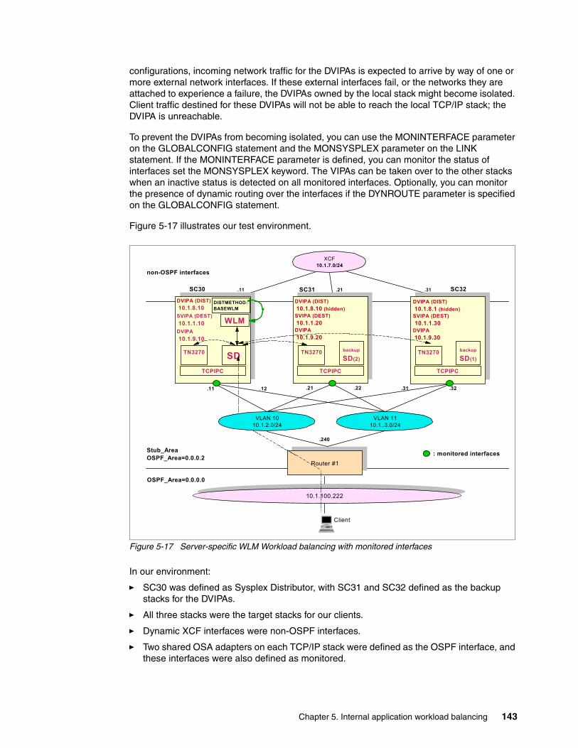
configurations, incoming network traffic for the DVIPAs is expected to arrive by way of one or more external network interfaces. If these external interfaces fail, or the networks they are attached to experience a failure, the DVIPAs owned by the local stack might become isolated. Client traffic destined for these DVIPAs will not be able to reach the local TCP/IP stack; the DVIPA is unreachable.
To prevent the DVIPAs from becoming isolated, you can use the MONINTERFACE parameter on the GLOBALCONFIG statement and the MONSYSPLEX parameter on the LINK statement. If the MONINTERFACE parameter is defined, you can monitor the status of interfaces set the MONSYSPLEX keyword. The VIPAs can be taken over to the other stacks when an inactive status is detected on all monitored interfaces. Optionally, you can monitor the presence of dynamic routing over the interfaces if the DYNROUTE parameter is specified on the GLOBALCONFIG statement.
Figure 5-17 illustrates our test environment.
Figure 5-17 Server-specific WLM Workload balancing with monitored interfaces
In our environment:
� SC30 was defined as Sysplex Distributor, with SC31 and SC32 defined as the backup stacks for the DVIPAs.
� All three stacks were the target stacks for our clients.
� Dynamic XCF interfaces were non-OSPF interfaces.
� Two shared OSA adapters on each TCP/IP stack were defined as the OSPF interface, and these interfaces were also defined as monitored.
DVIPA (DIST) 10.1.8.10 (hidden)SVIPA (DEST) 10.1.1.20DVIPA 10.1.9.20
Router #1
SC30 SC31 SC32
DVIPA (DIST) 10.1.8.1 (hidden)SVIPA (DEST) 10.1.1.30DVIPA 10.1.9.30
TCPIPC
SDTCPIPC TCPIPC
TN3270TN3270
WLM
backup
SD(2)
DISTMETHOD:BASEWLM
.11
XCF10.1.7.0/24
.21 .31
non-OSPF interfaces
Stub_AreaOSPF_Area=0.0.0.2
OSPF_Area=0.0.0.0
.11 .21 .31
.240
10.1.100.222
DVIPA (DIST) 10.1.8.10SVIPA (DEST) 10.1.1.10DVIPA 10.1.9.10
TN3270
VLAN 1010.1.2.0/24
VLAN 1110.1..3.0/24
.12 .22 .32
: monitored interfaces
backup
SD(1)
Client
Chapter 5. Internal application workload balancing 143

Although we only used one Layer 3 switch in our test configuration, you should always consider using at least two Layer 3 switch or routers for fault tolerance in a production environment.
Implementation tasksWe needed to complete the following implementation tasks:
1. Specify the MONINTERFACE and DYNROUTE parameters on the GLOBALCONFIG SYSPLEXMONITOR statement.
2. Specify the RECOVERY parameter on the GLOBALCONFIG SYSPLEXMONITOR statement.
3. Specify the DELAYJOIN and AUTOREJOIN parameters on the GLOBALCONFIG SYSPLEXMONITOR statement.
4. Configure the Sysplex Distributor stack, the target stacks, and the backup stacks with at least one DVIPA. The related statements will be defined in the TCPIP profiles and the OMPROUTE configuration files.
5. Configure the VIPAROUTE statements.
6. Specify the MONSYSPLEX parameter on the LINK statement of the interfaces to be monitored.
ConfigurationIn Example 5-40, we show the most important parts of our TCP/IP profile, which are necessary to monitor the interfaces and to detect and recover any failures.
Example 5-40 Profile TCPIPA SC30 Sysplex Distributor, Target and Backup
ARPAGE 20 GLOBALCONFIG NOTCPIPSTATISTICS SYSPLEXMONitor RECOVERY DYNROUTE MONINTERFACE DELAYJOIN AUTOREJOIN 1 IPCONFIG NODATAGRAMFWD SYSPLEXROUTINGIPCONFIG MULTIPATH PERCONNECTION IPCONFIG SOURCEVIPA PATHMTUDISC DYNAMICXCF 10.1.7.10 255.255.255.0 8 ; DEVICE OSA2080 MPCIPA LINK OSA2080L IPAQENET OSA2080 VLANID 10 MONSYSPLEX 2 DEVICE OSA20E0 MPCIPA LINK OSA20E0L IPAQENET OSA20E0 VLANID 11 MONSYSPLEX 2 DEVICE VIPA1 VIRTUAL 0 LINK VIPA1L VIRTUAL 0 VIPA1 ; VIPADynamic VIPADEFine MOVEable IMMEDiate 255.255.255.255 10.1.8.10 3 VIPADEFine MOVEable IMMEDiate 255.255.255.255 10.1.9.10 VIPADISTribute DISTMethod SERVERWLM 10.1.8.10 3 PORT 23 DESTIP 10.1.7.11 10.1.7.21 10.1.7.31 VIPAROUTE 10.1.7.11 10.1.1.10 4 VIPAROUTE 10.1.7.21 10.1.1.20 4 VIPAROUTE 10.1.7.31 10.1.1.30 4
Note: The Unreachable DVIPA Detection and Recovery function works with the DVIPA, which can be defined by the VIPADEFINE or VIPARANGE statement. Therefore, we defined DVIPAs on all stacks.
144 IBM z/OS V1R10 Communications Server TCP/IP Implementation Volume 3: High Availability, Scalability, and
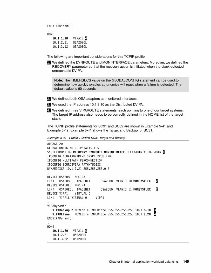
ENDVIPADYNAMIC; HOME 10.1.1.10 VIPA1L 4 10.1.2.11 OSA2080L 10.1.3.12 OSA20E0L
The following are important considerations for this TCPIP profile.
1. We defined the DYNROUTE and MONINTERFACE parameters. Moreover, we defined the RECOVERY parameter so that the recovery action is initiated when the stack detected unreachable DVIPA.
2. We defined both OSA adapters as monitored interfaces.
3. We used the IP address 10.1.8.10 as the Distributed DVIPA.
4. We defined three VIPAROUTE statements, each pointing to one of our target systems. The target IP address also needs to be correctly defined in the HOME list of the target stack.
The TCPIP profile statements for SC31 and SC32 are shown in Example 5-41 and Example 5-42. Example 5-41 shows the Target and Backup for SC31.
Example 5-41 Profile TCPIPB SC31 Target and Backup
ARPAGE 20 GLOBALCONFIG NOTCPIPSTATISTICS SYSPLEXMONITOR RECOVERY DYNROUTE MONINTERFACE DELAYJOIN AUTOREJOIN 1IPCONFIG NODATAGRAMFWD SYSPLEXROUTING IPCONFIG MULTIPATH PERCONNECTION IPCONFIG SOURCEVIPA PATHMTUDISC DYNAMICXCF 10.1.7.21 255.255.255.0 8 ; DEVICE OSA2080 MPCIPA LINK OSA2080L IPAQENET OSA2080 VLANID 10 MONSYSPLEX 2 DEVICE OSA20E0 MPCIPA LINK OSA20E0L IPAQENET OSA20E0 VLANID 11 MONSYSPLEX 2 DEVICE VIPA1 VIRTUAL 0 LINK VIPA1L VIRTUAL 0 VIPA1 ; VIPADynamic VIPABackup 2 MOVEable IMMEDiate 255.255.255.255 10.1.8.10 3 VIPADEFine MOVEable IMMEDiate 255.255.255.255 10.1.9.20 4 ENDVIPADynamic; HOME 10.1.1.20 VIPA1L 5 10.1.2.21 OSA2080L 10.1.3.22 OSA20E0L
Note: The TIMERSECS value on the GLOBALCONFIG statement can be used to determine how quickly sysplex autonomics will react when a failure is detected. The default value is 60 seconds.
Chapter 5. Internal application workload balancing 145

Example 5-42 shows the Target and Backup for SC32.
Example 5-42 Profile TCPIPC SC32 Target and Backup
ARPAGE 20 ; GLOBALCONFIG NOTCPIPSTATISTICS SYSPLEXMONITOR RECOVERY DYNROUTE MONINTERFACE DELAYJOIN AUTOREJOIN 1 IPCONFIG NODATAGRAMFWD SYSPLEXROUTING IPCONFIG MULTIPATH PERCONNECTION IPCONFIG SOURCEVIPA PATHMTUDISC DYNAMICXCF 10.1.7.31 255.255.255.0 8 ; DEVICE OSA2080 MPCIPA LINK OSA2080L IPAQENET OSA2080 VLANID 10 MONSYSPLEX 2 DEVICE OSA20E0 MPCIPA LINK OSA20E0L IPAQENET OSA20E0 VLANID 11 MONSYSPLEX 2 DEVICE VIPA1 VIRTUAL 0 LINK VIPA1L VIRTUAL 0 VIPA1 ; VIPADynamic VIPABackup 1 MOVEable IMMEDiate 255.255.255.0 10.1.8.10 3 VIPADEFine MOVEable IMMEDiate 255.255.255.0 10.1.9.30 4 ENDVIPADynamic ; HOME 10.1.1.30 VIPA1L 5 10.1.2.31 OSA2080L 10.1.3.32 OSA20E0L
The important information in this output includes:
1. We defined the same options as SC30.
2. We defined both OSA adapters to be monitored.
3. We defined SC31 as the first backup stack and SC32 as the second backup stack for SC30, by using the VIPABackup statement. Larger numerical rank values move the respective stacks closer to the beginning of the backup list.
4. We defined the non-Distributed DVIPA to enable the monitoring function on each stack.
5. We specified static VIPAs on the VIPAROUTE statement of SC30.
In the OMPROUTE configuration files, we configured the INTERFACE statement for the Dynamic XCF interfaces, because we assumed that our test environment only has the only OSA interfaces as the dynamic routing path.
VerificationWe used the following steps to verify our Sysplex Distributor implementation with the Unreachable DVIPA function:
1. Verify the sysplex group (EZBTCPCS) that the stacks should join.2. Verify the general dynamic VIPA and Sysplex Distributor setup.3. Verify that our VIPAROUTE definitions work.4. Verify the monitored interfaces setup.5. Verify that the Unreachable DVIPA detection and recovery function works.
146 IBM z/OS V1R10 Communications Server TCP/IP Implementation Volume 3: High Availability, Scalability, and

Normal statusWe used a Display XCF, GROUP,groupname command to verify that all three stacks 1 were joined into the same XCF group, as shown in Example 5-43.
Example 5-43 Display of XCF Group on SC30
SC30D XCF,GROUP,EZBTCPCS IXC332I 11.26.51 DISPLAY XCF 955 GROUP EZBTCPCS: SC30TCPIPA 1 SC31TCPIPB 1 SC32TCPIPC 1
To verify the general dynamic VIPA and Sysplex Distributor setup, we issued several commands:
� Display NETSTAT,VIPADYN� Display SYSPLEX,VIPADYN� Display NETSTAT,HOME
Issuing a NETSTAT,VIPADCFG command on SC30, shown in Example 5-44, provided helpful information about the Sysplex Distributor configuration.
Example 5-44 Display result of the NETSTAT,VIPADYN command on SC30
D TCPIP,TCPIPA,NETSTAT,VIPADYN EZD0101I NETSTAT CS V1R9 TCPIPA 741 DYNAMIC VIPA: IPADDR/PREFIXLEN: 10.1.9.10/32 STATUS: ACTIVE ORIGIN: VIPADEFINE 1 DISTSTAT: ACTTIME: 08/09/2007 15:51:27 2 IPADDR/PREFIXLEN: 10.1.8.10/32 STATUS: ACTIVE ORIGIN: VIPADEFINE 1 DISTSTAT: DIST/DEST 3 ACTTIME: 08/09/2007 15:51:27 2 VIPA ROUTE: DESTXCF: 10.1.7.11 TARGETIP: 10.1.1.10 RTSTATUS: DEFINED 4 DESTXCF: 10.1.7.21 TARGETIP: 10.1.1.20 RTSTATUS: ACTIVE 5 DESTXCF: 10.1.7.31 TARGETIP: 10.1.1.30 RTSTATUS: ACTIVE 5 5 OF 5 RECORDS DISPLAYED END OF THE REPORT
The important information in this output includes:
1. ORIGIN represents the original definition of DVIPA.
2. This is the time stamp indicating when the DVIPA was activated on the local stack, specified as Coordinated Universal Time (UTC).
3. This stack is the distributor stack as well as the destination stack for the Distributed DVIPA 10.1.8.10.
Chapter 5. Internal application workload balancing 147

4. The target IP address specified is on the local stack.
5. The target IP address specified is reachable from this stack, and it also means that the VIPAROUTE definition works.
Issuing a SYSPLEX,VIPADYN command, shown in Example 5-45, displays the relationship among the members of the sysplex group.
Example 5-45 Display result of the SYSPLEX,VIPADYN command on SC30
D TCPIP,TCPIPA,SYSPLEX,VIPADYN EZZ8260I SYSPLEX CS V1R9 747 VIPA DYNAMIC DISPLAY FROM TCPIPA AT SC30 IPADDR: 10.1.9.30 TCPNAME MVSNAME STATUS RANK DIST -------- -------- ------ ---- ---- TCPIPC SC32 ACTIVE LINKNAME: VIPL0A01090A IPADDR/PREFIXLEN: 10.1.9.10/32 ORIGIN: VIPADEFINE TCPNAME MVSNAME STATUS RANK DIST -------- -------- ------ ---- ---- TCPIPA SC30 ACTIVE IPADDR: 10.1.9.20 TCPNAME MVSNAME STATUS RANK DIST -------- -------- ------ ---- ---- TCPIPB SC31 ACTIVE LINKNAME: VIPL0A01080A IPADDR/PREFIXLEN: 10.1.8.10/32 ORIGIN: VIPADEFINE TCPNAME MVSNAME STATUS RANK DIST -------- -------- ------ ---- ---- TCPIPA SC30 ACTIVE1 BOTH TCPIPB SC31 BACKUP10022 DEST TCPIPC SC32 BACKUP10012 DEST 6 OF 6 RECORDS DISPLAYED
Several fields show important information of members in the sysplex group.
1. STATUS represents the actual status of the TCP/IP stacks.
2. RANK shows which backup stack will take over the distributor stack when the primary Sysplex Distributor is unreachable or goes down.
A NETSTAT,HOME command, as shown in Example 5-46, can display the DVIPAs that were generated as active.
Example 5-46 Display result of the NETSTAT,HOME command on all stacks
SC30D TCPIP,TCPIPA,NETSTAT,HOME EZD0101I NETSTAT CS V1R9 TCPIPA 759 HOME ADDRESS LIST: LINKNAME: VIPA1L ADDRESS: 10.1.1.10...
148 IBM z/OS V1R10 Communications Server TCP/IP Implementation Volume 3: High Availability, Scalability, and

LINKNAME: VIPL0A01080A ADDRESS: 10.1.8.10 2 FLAGS:LINKNAME: VIPL0A01090A ADDRESS: 10.1.9.20 1 FLAGS: 9 OF 9 RECORDS DISPLAYED END OF THE REPORT
SC31D TCPIP,TCPIPB,NETSTAT,HOME EZD0101I NETSTAT CS V1R9 TCPIPB 850 HOME ADDRESS LIST: LINKNAME: VIPA1L ADDRESS: 10.1.1.20 FLAGS: PRIMARY .. .LINKNAME: VIPL0A010914 ADDRESS: 10.1.9.20 1 FLAGS: LINKNAME: VIPL0A01080A ADDRESS: 10.1.8.10 2 FLAGS: INTERNAL 2 LINKNAME: LOOPBACK ADDRESS: 127.0.0.1 FLAGS: INTFNAME: LOOPBACK6 ADDRESS: ::1 TYPE: LOOPBACK FLAGS: 9 OF 9 RECORDS DISPLAYED END OF THE REPORT...
SC32D TCPIP,TCPIPC,NETSTAT,HOME EZD0101I NETSTAT CS V1R9 TCPIPC 287 HOME ADDRESS LIST: LINKNAME: VIPA1L ADDRESS: 10.30.1.221 FLAGS: PRIMARY LINKNAME: OSA2080L ADDRESS: 10.30.2.222 FLAGS: LINKNAME: OSA20E0L ADDRESS: 10.30.3.225 FLAGS: LINKNAME: EZASAMEMVS ADDRESS: 10.1.7.30 FLAGS: LINKNAME: IQDIOLNK0A1E1466 ADDRESS: 10.1.7.30 FLAGS: LINKNAME: VIPL0A01091E
Chapter 5. Internal application workload balancing 149

ADDRESS: 10.30.1.222 1 FLAGS: LINKNAME: VIPL0A01080A ADDRESS: 10.1.8.10 2 FLAGS: INTERNAL 2 LINKNAME: LOOPBACK ADDRESS: 127.0.0.1 FLAGS: INTFNAME: LOOPBACK6 ADDRESS: ::1 TYPE: LOOPBACK FLAGS: 9 OF 9 RECORDS DISPLAYED END OF THE REPORT
Key information includes:
1. These IP addresses are Non-Distributed DVIPA.
2. This is the Distributed DVIPA.
3. INTERNAL represents internally generated VIPAs that are not advertised to routing daemon.
We issued a NETSTAT,CONFIG command and a NETSTAT,DEvlinks command, to verify that the Unreachable DVIPA detection and recovery function was correctly defined.
Example 5-47 shows the output from issuing a NETSTAT,CONFIG command.
Example 5-47 Display result of the NETSTAT,CONFIG command on SC30
D TCPIP,TCPIPA,NETSTAT,CONFIG EZD0101I NETSTAT CS V1R9 TCPIPA 713 TCP CONFIGURATION TABLE: ...GLOBAL CONFIGURATION INFORMATION: TCPIPSTATS: NO ECSALIMIT: 0000000K POOLLIMIT: 0000000K MLSCHKTERM: NO XCFGRPID: IQDVLANID: 0 SYSPLEXWLMPOLL: 330722956 SYSPLEX MONITOR: TIMERSECS: 0060 RECOVERY: YES DELAYJOIN: YES AUTOREJOIN: YES MONINTF: YES 1 DYNROUTE: YES 2
Important keywords on the SYSPLEXMONITOR parameter are:
1. MONINTF: YES indicates that the TCP/IP stack is monitoring the status of network interfaces that have the MONSYSPLEX parameter specified on the LINK statement.
2. DYNROUTE: YES indicates that the TCP/IP stack is monitoring the presence of dynamic routes over monitored network interfaces that have the MONSYSPLEX parameter specified on the LINK statement.
150 IBM z/OS V1R10 Communications Server TCP/IP Implementation Volume 3: High Availability, Scalability, and

In Example 5-48, which is the output of the NETSTAT,DEvlinks command on SC30, MONSYSPLEX: YES marked as 1 indicates that the status of this link is being monitored by Sysplex Autonomics.
Example 5-48 Display result of the NETSTAT,DEvlinks on SC30
D TCPIP,TCPIPA,NETSTAT,DEV EZD0101I NETSTAT CS V1R9 TCPIPA 725 DEVNAME: OSA2080 DEVTYPE: MPCIPA DEVSTATUS: READY LNKNAME: OSA2080L LNKTYPE: IPAQENET LNKSTATUS: READY NETNUM: N/A QUESIZE: N/A SPEED: 0000001000 IPBROADCASTCAPABILITY: NO CFGROUTER: NON ACTROUTER: NON ARPOFFLOAD: YES ARPOFFLOADINFO: YES ACTMTU: 8992 VLANID: 30 VLANPRIORITY: DISABLED DYNVLANREGCFG: NO DYNVLANREGCAP: YES READSTORAGE: GLOBAL (4096K) INBPERF: BALANCED CHECKSUMOFFLOAD: YES SEGMENTATIONOFFLOAD: YES SECCLASS: 255 MONSYSPLEX: YES 1 ..DEVNAME: OSA20E0 DEVTYPE: MPCIPA DEVSTATUS: READY LNKNAME: OSA20E0L LNKTYPE: IPAQENET LNKSTATUS: READY NETNUM: N/A QUESIZE: N/A SPEED: 0000001000 IPBROADCASTCAPABILITY: NO CFGROUTER: NON ACTROUTER: NON ARPOFFLOAD: YES ARPOFFLOADINFO: YES ACTMTU: 8992 VLANID: 31 VLANPRIORITY: DISABLED DYNVLANREGCFG: NO DYNVLANREGCAP: YES READSTORAGE: GLOBAL (4096K) INBPERF: BALANCED CHECKSUMOFFLOAD: YES SEGMENTATIONOFFLOAD: YES SECCLASS: 255 MONSYSPLEX: YES 1..
You can issue the NETSTAT,VDPT,DETAIL command and the NETSTAT,VCRT,DETAIL command, as shown in Example 5-49, Example 5-50, and Example 5-51, to verify that the Sysplex Distributor works correctly, after TN3270E sessions are started.
For more information about each field of these displays, refer to Example 5-17 on page 126 and Example 5-18 on page 127 and to z/OS Communications Server: IP System Administrator’s Commands, SC31-8781.
Example 5-49 Display result of the NETSTAT,VDPT,DETAIL command on SC30
D TCPIP,TCPIPA,NETSTAT,VDPT,DETAIL EZD0101I NETSTAT CS V1R9 TCPIPA 796 DYNAMIC VIPA DESTINATION PORT TABLE: DEST: 10.1.8.10..23 DESTXCF: 10.1.7.10 TOTALCONN: 0000000000 RDY: 000 WLM: 00 TSR: 100 FLG: SERVERWLM
Chapter 5. Internal application workload balancing 151

TCSR: 100 CER: 100 SEF: 100 ABNORM: 0000 HEALTH: 100 ACTCONN: 0000000000 QOSPLCACT: *DEFAULT* W/Q: 00 DEST: 10.1.8.10..23 DESTXCF: 10.1.7.20 TOTALCONN: 0000000002 RDY: 001 WLM: 15 TSR: 100 FLG: SERVERWLM TCSR: 100 CER: 100 SEF: 100 ABNORM: 0000 HEALTH: 100 ACTCONN: 0000000002 QOSPLCACT: *DEFAULT* W/Q: 15 DEST: 10.1.8.10..23 DESTXCF: 10.1.7.30 TOTALCONN: 0000000000 RDY: 001 WLM: 16 TSR: 100 FLG: SERVERWLM TCSR: 100 CER: 100 SEF: 100 ABNORM: 0000 HEALTH: 100 ACTCONN: 0000000000 QOSPLCACT: *DEFAULT* W/Q: 16 3 OF 3 RECORDS DISPLAYED END OF THE REPORT
Example 5-50 Display result of the NETSTAT,VCRT,DETAIL command on SC30
D TCPIP,TCPIPA,NETSTAT,VCRT,DETAIL EZD0101I NETSTAT CS V1R9 TCPIPA 805 DYNAMIC VIPA CONNECTION ROUTING TABLE: DEST: 10.1.8.10..23 SOURCE: 10.1.100.222..1436 DESTXCF: 10.1.7.20 POLICYRULE: *NONE* POLICYACTION: *NONE* INTF: OSA2080L VIPAROUTE: YES GW: 10.30.2.242 DEST: 10.1.8.10..23 SOURCE: 10.1.100.222..1437 DESTXCF: 10.1.7.20 POLICYRULE: *NONE* POLICYACTION: *NONE* INTF: OSA2080L VIPAROUTE: YES GW: 10.30.2.242 2 OF 2 RECORDS DISPLAYED END OF THE REPORT
Example 5-51 Display result of the NETSTAT,VCRT,DETAIL command on a target stack SC31
D TCPIP,TCPIPB,NETSTAT,VCRT,DETAIL EZD0101I NETSTAT CS V1R9 TCPIPB 859 DYNAMIC VIPA CONNECTION ROUTING TABLE: DEST: 10.1.8.10..23 SOURCE: 10.1.100.222..1436 DESTXCF: 10.1.7.20
152 IBM z/OS V1R10 Communications Server TCP/IP Implementation Volume 3: High Availability, Scalability, and

POLICYRULE: *NONE* POLICYACTION: *NONE* DEST: 10.1.8.10..23 SOURCE: 10.1.100.222..1437 DESTXCF: 10.1.7.20 POLICYRULE: *NONE* POLICYACTION: *NONE* 2 OF 2 RECORDS DISPLAYED END OF THE REPORT
Detection and recoveryWe performed two test scenarios to verify that the unreachable DVIPA detection and recovery function works correctly:
1. Stop all two OSA interfaces of SC30.2. Stop the relevant routing process of an intermediate router.
Scenario 1After we certified that all the stacks were joined, we stopped both OSA interfaces (OSA2080 and OSA20E0) on SC30 and the takeover occurred about 60 seconds after, which is the default TIMERSECS value.
We saw some Syslog messages, as shown in Example 5-52.
Example 5-52 Syslog message of SC30 and SC31 (Scenario 1)
SC30 *EZD1209E TCPIPA DETERMINED THAT ALL MONITORED INTERFACES WERE NOT ACTIVE FOR AT LEAST 60 SECONDS 1 SC30 *EZZ9676E SYSPLEX PROBLEM DETECTION CLEANUP HAS SUCCEEDED FOR TCPIPA 2SC31 EZZ8301I VIPA 10.1.8.10 TAKEN OVER FROM TCPIPA ON SC30
The following detection and recovery messages are involved:
1. EZD1209E indicates that sysplex problem detection has determined that all monitored interfaces are inactive.
2. EZZ9676E indicates that sysplex problem detection caused the stack to leave the sysplex group and cleared up all DVIPAs.
We checked the status of Sysplex Distributor, using several NETSTAT commands and a SYSPLEX command, as shown in Example 5-53, Example 5-54, Example 5-55, and Example 5-56.
Example 5-53 Display of XCF group of SC30 (Scenario 1)
SC30D XCF,GROUP,EZBTCPCS IXC332I 13.29.37 DISPLAY XCF 294 GROUP EZBTCPCS: SC30TCPIPA SC31TCPIPB SC32TCPIPC 1
Chapter 5. Internal application workload balancing 153

Example 5-54 Display result of the NETSTAT,VIPADCFG command on SC31 (Scenario 1)
SC31D TCPIP,TCPIPB,NETSTAT,VIPADCFG EZD0101I NETSTAT CS V1R9 TCPIPB 069 DYNAMIC VIPA INFORMATION: VIPA BACKUP: IPADDR/PREFIXLEN: 10.1.8.10 RANK: 002 MOVEABLE: SRVMGR: VIPA DEFINE: IPADDR/PREFIXLEN: 10.1.9.20/32 MOVEABLE: IMMEDIATE SRVMGR: NO VIPA DISTRIBUTE: 2 DEST: 10.1.8.10..23 DESTXCF: 10.1.7.11 SYSPT: NO TIMAFF: NO FLG: SERVERWLM DEST: 10.1.8.10..23 DESTXCF: 10.1.7.21 SYSPT: NO TIMAFF: NO FLG: SERVERWLM DEST: 10.1.8.10..23 DESTXCF: 10.1.7.31 SYSPT: NO TIMAFF: NO FLG: SERVERWLM END OF THE REPORT
Example 5-55 Display result of the SYSPLEX,VIPADYN command on SC31 (Scenario 1)
SC31D TCPIP,TCPIPB,SYSPLEX,VIPADYN EZZ8260I SYSPLEX CS V1R9 071 VIPA DYNAMIC DISPLAY FROM TCPIPB AT SC31 IPADDR: 10.1.9.30 TCPNAME MVSNAME STATUS RANK DIST -------- -------- ------ ---- ---- TCPIPC SC32 ACTIVE LINKNAME: VIPL0A010914 IPADDR/PREFIXLEN: 10.1.9.20/32 ORIGIN: VIPADEFINE TCPNAME MVSNAME STATUS RANK DIST -------- -------- ------ ---- ---- TCPIPB SC31 ACTIVE LINKNAME: VIPL0A01080A IPADDR/PREFIXLEN: 10.1.8.10/32 ORIGIN: VIPABACKUP TCPNAME MVSNAME STATUS RANK DIST -------- -------- ------ ---- ---- TCPIPB SC31 ACTIVE BOTH 3 TCPIPC SC32 BACKUP 001 DEST 4 OF 4 RECORDS DISPLAYED
154 IBM z/OS V1R10 Communications Server TCP/IP Implementation Volume 3: High Availability, Scalability, and

Example 5-56 Display result of the NETSTAT,HOME command on SC31 (Scenario 1)
SC31D TCPIP,TCPIPB,NETSTAT,HOME EZD0101I NETSTAT CS V1R9 TCPIPB 073 HOME ADDRESS LIST: LLINKNAME: VIPL0A01080A ADDRESS: 10.1.8.10 FLAGS: 4
Important information includes the following:
1. SC30 TCPIPA left the XCF group of EZBTCPCS.
2. SC31 took the VIPA DISTRIBUTE configuration from SC30.
3. SC31 shifted the BOTH status from the DEST status.
4. SC31 FLAGS is not INTERNAL any longer.
Next, we started an OSA interface OSA2080 of SC30 again. A few seconds later the takeback process occurred and syslog messages were displayed, as shown in Example 5-57.
Example 5-57 Syslog messages of SC30 and SC31 (Scenario 1)
SC30 *EZD1212E TCPIPA DELAYING SYSPLEX PROFILE PROCESSING - NO DYNAMIC ROUTES OVER MONITORED INTERFACES WERE FOUND 1 ... ...SC30 EZD1176I TCPIPA HAS SUCCESSFULLY JOINED THE TCP/IP SYSPLEX GROUP EZBTCPCS SC30 EZZ8302I VIPA 10.1.8.10 TAKEN FROM TCPIPB ON SC31 SC30 EZD1192I THE VIPADYNAMIC CONFIGURATION WAS SUCCESSFULLY RESTORED FOR TCPIPA SC30 EZD1214I INITIAL DYNAMIC VIPA PROCESSING HAS COMPLETED FOR TCPIPA SC31 EZZ8303I VIPA 10.1.8.10 GIVEN TO TCPIPA ON SC30
1. EZD1212E indicates that TCP/IP joined a sysplex group and finished processing the sysplex definitions when at least one dynamic route over monitored interfaces is found.
Scenario 2We stopped the relevant routing process of an intermediate router. The takeover occurred about 60 seconds after. However, we received a message that was different from Scenario 1, as shown in Example 5-58.
Example 5-58 Syslog messages of SC30 and SC31 (Scenario 2)
SC30 *EZD1210E TCPIPA DETERMINED THAT NO DYNAMIC ROUTES OVER MONITORED INTERFACES WERE FOUND FOR AT LEAST 60 SECONDS 1 SC30 *EZZ9676E SYSPLEX PROBLEM DETECTION CLEANUP HAS SUCCEEDED FOR TCPIPA SC31 EZZ8301I VIPA 10.1.8.10 TAKEN OVER FROM TCPIPA ON SC30
1. EZD1210E indicates that sysplex problem detection has determined that no dynamic routes over monitored interfaces were found.
Chapter 5. Internal application workload balancing 155

5.3 Problem determination
To diagnose a Sysplex Distributor problem, you can use a combination of the Netstat command from the system console and display sysplex commands to provide a clear picture of the sysplex. Before beginning problem determination, however, you should understand the entire sysplex environment. Creating a diagram of your configuration, including all the IP addresses for all the paths involved, will be useful. Saving and reviewing all related log files can also be helpful in narrowing down where the problem might be located.
When the problem is actually occurring, you can also use certain commands to help with the problem determination. The Netstat command has several sysplex-related reports that can be used to verify the status of your environment.
You can use the following commands to provide the necessary diagnosis information:
� Run the display Netstat CONFIG/-f command on the distributing stack and all target stacks to confirm that the correct IPCONFIG and IPCONFIG6 options have been specified.
� Run the display Netstat VIPADYN/-v command on the distributing stack to verify that the DVIPA status is ACTIVE and the distribution status is DIST or DIST/DEST.
� Run the display command Netstat VIPADYN/-v on the target stacks to verify that they have activated the distributed DVIPA and have it designated as a DEST.
� Run the Sysplex VIPADyn command from any stack in the sysplex to get a global view of how and where DVIPAs are defined within the sysplex and what their status is on each stack. Deactivated DVIPA configurations do not appear in this display.
� Run the Netstat VDPT/-O command on the distributing stack to confirm that there are target stacks available with server applications ready.
� Examine the READY (RDY) count fields. The READY (RDY) count is the number of servers that are currently listening on the DVIPA and PORT specified in the DEST: field on the target stack that was identified by the DESTXCF address.
� Check the TotalConn count to see the distribution history. This is a cumulative count of the number of connections that have been forwarded by the distributing stack to each target stack.
� Use the Netstat VCRT/-V command on the distributing stack to check whether there are any active connections that are being routed by the distributor. If you run the command with the keyword DETAIL (d tcpip,tcpcs,net,vcrt,detail), you can see the policy rule and policy action that each connection maps to.
� Go to the target stacks represented by the DESTXCF ADDR field in the VCRT or VDPT display and run the Netstat ALLCONN(/-a),IPA=destxcf-addr display command to see the connections on the target stack.
These are the suggested steps to diagnose a sysplex problem on z/OS Communications Server (based on the information presented in z/OS Communications Server: IP Diagnosis Guide, GC31-8782):
1. Determine that all the stacks that you expect to be communicating are in the same sysplex or subplex (if subplexing is being used). Run the D XCF,GROUP MVS command to determine what groups are being used in the sysplex.
2. For problems where the actual DVIPAs defined on a stack are not what you expected, check the current definitions using the Netstat VIPADCFG/-F display command on the distributing stack to confirm that it is configured to distribute the DVIPA and determine how it is to be distributed.
156 IBM z/OS V1R10 Communications Server TCP/IP Implementation Volume 3: High Availability, Scalability, and

3. For Sysplex Distributor workload monitoring, use the commands Netstat VDPT/-O and Netstat VCRT/-V on the distributing stack. If the output from these commands is not what you expect, use the command Sysplex VIPADyn to gain an overall picture of all DVIPA activity in your sysplex.
4. If the output from the command Sysplex VIPADyn reveals an expected target stack not listed for a distributed DVIPA, execute the command Netstat CONFIG/-f on the target stack in question. This helps to identify configuration problems on that stack. Note what is required of target stacks. Also use the command Netstat ALLCONN(/-a),IPA=destxcf-addr to verify that a server application has indeed been activated and bound to the correct port.
5. To help follow the flow of packets into and throughout the sysplex, use a CTRACE with options XCF, TCP, and SYSTCPDA on participating stacks to:
– Identify the connection being received by the distributing stack– Determine the stack to which the connection is forwarded– Verify the connection being forwarded– Determine the expected target stack receiving and processing the connection
After the connection has been established, subsequent packets can be followed in the same manner. When the connection is terminated, CTRACE records record target stacks, cleans up the connection, and notifies the distributing stack.
For further information about Sysplex Distributor diagnosis, refer to z/OS Communications Server: IP Diagnosis Guide, GC31-8782.
Chapter 5. Internal application workload balancing 157

158 IBM z/OS V1R10 Communications Server TCP/IP Implementation Volume 3: High Availability, Scalability, and

Chapter 6. External application workload balancing
With external application workload distribution, decisions for load balancing are made by external devices. Such devices typically have very robust capabilities and are often part of a suite of networking components. They usually have a significant amount of processing capacity, giving them the ability to make decisions using higher-layer information buried deep inside of datagrams rather than just using IP addresses, including application-specific information such as HTTP (or FTP) URLs.
The latest improvement in this area is the ability of external load balancers to be z/OS sysplex-aware, all the way to the application level. This is achieved by implementing the z/OS Load Balancing Advisor (LBA) solution that uses the Server/Application State Protocol (SASP).
This chapter discusses the following topics.
6
Section Topic
6.1, “Basic concepts of external load balancing” on page 160
Basic concepts of external application workload balancing and key characteristics
6.2, “External load balancer without LBA/SASP” on page 168
A scenario without LBA/SASP including dependencies, advantages, considerations, and recommendations Implementation tasks, configuration examples, and problem determination suggestions
6.3, “External load balancer with LBA/SASP” on page 180
A scenario with LBA/SASP including its dependencies, advantages, considerations, and recommendationsImplementation tasks, configuration examples, and problem determination suggestions
© Copyright IBM Corp. 2009. All rights reserved. 159

6.1 Basic concepts of external load balancing
From a z/OS viewpoint, there are two types of external load balancers available today. One type bases decisions completely on parameters in the external mechanism, and the other type uses sysplex awareness matrixes for each application and each z/OS system as part of the decision process. Which technique is best depends on many factors, but the best method usually involves knowledge of the health and status of the application-instances and the z/OS systems. Enhancements in Workload Manager (WLM) allow the export of status data for each application instance, as well as the z/OS system itself.
The content in this chapter is based on workload balancing with the use of switches and a Content Switching Module (CSM) as the load balancing device. The CSM is one of the external load balancers that supports SASP.
If optimized multitier application load balancing is planned within an intra-sysplex environment in addition to external load balancing, refer to Chapter 7, “Intra-sysplex workload balancing” on page 201 for further information about this topic.
6.1.1 Understanding directed mode load balancing
Directed mode load balancing works by changing the destination IP address of the inbound IP packets to the IP address of the chosen target stack. One of the advantages of directed mode is that there can be any number of router hops in between the load balancer and the target stacks.
A characteristic of directed mode is that outbound packets must be directed back through the load balancer so that the load balancer can change the source IP address of the outbound IP packets from the IP address of the target stack to the cluster IP address. If this is not done, the remote client would reject the response because it would appear to come from an IP address other than the one it sent a request to. Another reason that outbound packets must be directed back using the load balancer is that the load balancer keeps track of the flows passing through it and this information is used for fault tolerance purposes.
There are two ways to ensure outbound routing back through the load balancer:
1. The load balancer can be configured to change only the destination IP address in inbound IP packets, and not the source IP address. In this case the target stack responds with IP packets back directly to the client IP address. These packets must be directed to the load balancer for it to change the source IP address in the outbound packets. This can be achieved in two ways:
– By having all outbound packets routed through the load balancer (using a default route definition on the target stacks).
– By having the routing infrastructure between the load balancer and the target node implement policy-based routing (PBR) where the routers recognize IP packets from the clustered servers (based on source IP address, source port number, or both). In this configuration, the router sends only those packets back through the load balancer, while outbound packets for workload that were not balanced are routed directly back to the clients. This is known as server NAT mode and is illustrated in Figure 6-1.
160 IBM z/OS V1R10 Communications Server TCP/IP Implementation Volume 3: High Availability, Scalability, and Performance

Figure 6-1 Server NAT with policy-based routing
2. You can configure the load balancer to change both the destination IP address and the source IP address in the inbound IP packets, known as server NAT and client NAT mode. The advantage of this method is that outbound IP packets from the target stacks are sent with the destination IP address of the load balancer. The load balancer then changes the packet to match the original cluster IP address as source and client IP address as destination. This is illustrated in Figure 6-2.
Figure 6-2 Server NAT with client NAT
DestIP=10.1.1.10, DestPort=23SrcIP=10.1.100.223, SrcPort=2658
DestIP=10.1.1.10, DestPort=23SrcIP=10.1.100.223, SrcPort=2658
DestIP=10.1.100.223, DestPort=2658SrcIP=10.1.1.10, SrcPort=23
DestIP=10.1.100.223, DestPort=2658SrcIP=10.1.1.10, SrcPort=23
Real Client Load Balancer Real Server
10.1.100.223Port 2658
10.1.1.10Port 23
10.1.100.241Port 23
Translate
Translate
Translate
DestIP=10.1.1.10, DestPort=23SrcIP=10.1.100.223, SrcPort=2658
DestIP=10.1.100.241, DestPort=23SrcIP=10.1.1.20, SrcPort=4711
DestIP=10.1.1.20, DestPort=4711SrcIP=10.1.100.241, SrcPort=23
DestIP=10.1.100.223, DestPort=2658SrcIP=10.1.1.10, SrcPort=23
Real Client Load Balancer Real Server
10.1.100.223Port 2658
10.1.1.10Port 23
10.1.100.241Port 23
10.1.1.20Port 4711
Translate
Translate
Translate
Chapter 6. External application workload balancing 161

From a target server view, it appears that all connections come from one client source IP address (that of the load balancer), but each client connection comes from a different source port number on that load balancer. One consequence is that servers cannot see the real client IP address, and this can complicate diagnosing network-related problems.
Client NATing can have an impact on z/OS networking policy functions. Networking policies on z/OS might apply network QoS differentiated services, selection of Intrusion Detection Service (IDS) actions, and Traffic Regulation (TR) limitations. z/OS networking policies are specified using policy conditions and actions. The conditions can be defined in various ways, one of which is to use the client source IP address.
One example is to apply high-priority outbound treatment to traffic that is destined for a specific user community, such as all IP addresses that belong to the client query department. If client NATing is used by the load balancer, all inbound packets appear to come from one IP address (that of the load balancer) and networking policy conditions that were defined based on the real client IP addresses are not applied to that traffic.
Another z/OS function that is impacted by client NATing is NETACCESS rules. These can be used to authorize individual z/OS users to communicate with selected sections of a network identified by prefix definitions in the NETACCESS policies in the z/OS TCP/IP configuration files. NETACCESS rules might also be used to assign Multi Level Security (MLS) labels to inbound IP packets in an MLS-enabled security environment.
If z/OS networking policies are based on client IP addresses, or if NETACCESS rules are in use, client NATing should be used with care, because it might disrupt the operation of those functions.
To complete this discussion, care is also needed when using client NATing to TN3270 servers that use the client source IP address or host name to choose TN3270 connection options, such as selecting an LU name or a primary SNA application for a given connection.
6.1.2 z/OS Load Balancer Advisor
The z/OS Load Balancer Advisor (LBA) is a component that allows any external load balancing solution to become sysplex-aware. The external load balancer must support the Server Application State Protocol (SASP) to obtain sysplex information through this function. The general LBA flow is illustrated in Figure 6-3.
162 IBM z/OS V1R10 Communications Server TCP/IP Implementation Volume 3: High Availability, Scalability, and Performance

Figure 6-3 z/OS Load Balancing Advisor overview
The z/OS Load Balancing Advisor consists of two z/OS applications:
� z/OS z/OS Load Balancing Advisor
The advisor is an MVS started task and has one primary instance per sysplex. A backup advisor can be implemented as a secondary instance. The advisor collects information from z/OS Load Balancing Agents in the sysplex using a private protocol through a TCP connection. This z/OS sysplex awareness information is then communicated to the external load balancers using the SASP protocol.
The advisor provides awareness information from any TCP/UDP server application within the sysplex. It acts as the SASP server using TCP Port 3860 (configurable) and can communicate with multiple external load balancers.
� z/OS z/OS Load Balancing Agent
An agent is an MVS started task and has one instance per system. The agent collects information about z/OS and applications. The information is then sent to the advisor using the private protocol.
The sysplex awareness information is collected by the advisor and sent to the external load balancer so the load balancer can decide which application instance is best for the next request. The recommendations are derived from the following key components:
� State of the target application and system
This includes an indication of whether the target application and target system are currently active, enabling the load balancer to exclude systems that are not active or do not have the desired application running.
� z/OS Workload Management (WLM) system-wide recommendations
WLM recommendations provide a relative measure of a target system’s ability to handle new workload, as compared to other target systems in the sysplex. WLM recommendations are derived from many measurements, including each system’s available CPU capacity or capacity that can be displaced by higher importance workloads. The latter is important where systems might be 100% utilized, but are running work that
Server instance
Server instance
Server instance
z/OS LB agent
Work requests
Work requests
Private protocol control flows
SASP control flows
Load Balancer
z/OS LB agent
z/OS LB agent
z/OS Sysplex
z/OS LB advisor
Chapter 6. External application workload balancing 163

has a lower importance (as defined by the WLM policy) and can be displaced by higher importance workload.
� z/OS WLM server-specific recommendations
These recommendations are similar to the WLM system-wide recommendations, but also contain an indication of how well individual server applications are doing compared to the WLM policy goals that have been specified for that workload. These recommendations can be very useful in helping load balancers avoid selecting application servers that are experiencing performance problems (that is, not meeting the specified WLM policy goals).
� Application server health from a TCP/IP perspective
TCP/IP statistics for target applications are monitored to determine whether specific server applications are encountering problems keeping up with the current workload. For example, are requests being rejected because the backlog queue is full? In situations such as this, the load balancer can direct fewer connections to any application that is experiencing these problems. Recommendations are provided for both UDP and TCP server applications. These recommendations are referred to as Communications Server weights in this chapter.
The information sent to the load balancer is represented in the form of a weight that is composed of two main elements:
� WLM weight
This refers to the WLM weight that is known from other WLM-based load balancing solutions, such as Sysplex Distributor. The WLM weight has a numeric value between 0 and 64.
� Communications Server weight
The Communications Server weight is calculated based on the availability of the actual application instances (are they up and ready to accept workload) and how well TCP/IP and the individual application instance process the workload that is sent to them. The Communications Server weight has a numeric value between 0 and 100.
There are several reasons for the calculation of the Communications Server weight. One reason is to prevent a stalled application instance from being sent more work. Another is to proactively react to an application instance that is becoming overloaded. It can accept new connections, but the size of the backlog queue increases over time and is approaching the max backlog queue size.
The final weight that is sent to the load balancer is calculated by combining the WLM and Communications Server weights into a single metric:
Final weight = (WLM weight * CS weight) / 100
6.1.3 Server/Application State Protocol (SASP)
The Server/Application State Protocol (SASP) is an open protocol. The SASP protocol is used for communication between external load balancers and the advisor. The information that is exchanged includes:
� Registration of members from external load balancers that are interested in load balancing
� Requests from external load balancers
� Recommendations to external load balancers
� Deregistration of members from external load balancers that are no longer interested in load balancing
164 IBM z/OS V1R10 Communications Server TCP/IP Implementation Volume 3: High Availability, Scalability, and Performance

The registration process covers two types of groups, system-level groups and application-level groups, as explained here:
� System-level groups
This group is only represented by a list of IP addresses that are matched to TCP/IP stacks in the sysplex. The group includes WLM weights for the logical partition (LPAR). The Communications Server weight indicates whether the IP address is active in the sysplex. A value of 0 means quiesced and a value of 100 means not quiesced. Load Balancing Advisor (LBA) displays show a protocol value of 0 for system-level groups.
� Application-level groups
This group is represented by a list of IP addresses, protocols (TCP and UDP), and ports that are matched to server address spaces. The group includes WLM weights for the server address spaces. Communications Server weights indicate how well the server instances are performing. LBA displays show protocols as TCP or UDP with the registered port numbers.
When the external load balancer connects to the advisor, it indicates how it wants the information exchanged. This gives the load balancer the ability to select the best fit for itself. The choices available are pull model and push model:
� Pull model
The advisor suggests a frequency interval, but it is up to the load balancer to choose the frequency with which it wants to receive the weights.
� Push model
The load balancer requests the advisor to push weights down at certain intervals or when the weights change.
For both models, the recommendations (weights) can be sent for all registered members or only for those with changes to their weights.
With more frequent updates, the workload is distributed more accurately. The cost of more frequent updates is more flows in the network, both between LBA and agents, and LBA and external load balancers, as well as cycles used in LBA and load balancers.
Chapter 6. External application workload balancing 165

6.1.4 External load balancer without LBA/SASP
There are several products available today that perform load balancing of IP traffic. The example in this chapter was built using the Content Switching Module (CSM) and has the general structure shown in Figure 6-4.
Figure 6-4 External load balancing without LBA/SASP
The external load balancer function is implemented as an active or standby pair for fault tolerance. The CSMs are used to exchange state information so that the existing connections continue nondisruptively in case of a failure in the active CSM.
The external load balancer receives user requests for the application cluster and forwards the requests to an application instance within the application cluster, according to the configuration in the load balancer. The load balancer is responsible for deciding which application instance to use for each new connection. Remember that, in this design, the decision is made without any knowledge of the current workload inside z/OS and the application.
A way for the load balancer to keep track of the availability of each application instance is to poll each application instance. This polling technique is handled in several ways and is different for different vendors. An example of a simple polling technique is Internet Control Message Protocol (ICMP), where the load balancer assumes that the application instance is operating correctly if it receives an ICMP reply from the application instance IP address.
TCPIPA
LPAR 1
CSM CSM
Active Standby
Router
TCPIPB
LPAR 2
TCPIPC
LPAR 3
IP Network
Router
166 IBM z/OS V1R10 Communications Server TCP/IP Implementation Volume 3: High Availability, Scalability, and Performance

6.1.5 External load balancer with LBA/SASP
The example for this mode was built using a product that supports SASP. The general structure of the example is shown in Figure 6-5.
Figure 6-5 External load balancing with LBA/SASP
z/OS sysplex assists the external load balancer with recommendations as to which application instance is the best candidate for the next request. This is done by implementing the z/OS Load Balancing Advisor solution that communicates the recommendations to the external load balancer using the SASP protocol. The load balancer must support the SASP protocol and include the recommendations from LBA when it decides which application instance to use for the next request. The external load balancer function is implemented as an active or standby pair for fault tolerance. The external load balancer exchange state information so that existing connections continue nondisruptively in case of a failure in the active external load balancer.
The external load balancer receives user requests for the application cluster and forwards the requests to an application instance within the application cluster according to the configuration in the load balancer. The load balancer can combine the recommendations from LBA with its own techniques, such as ICMP polling.
6.1.6 Importance of external application workload balancing
There are many reasons for choosing an external device to be responsible for load balancing for a z/OS sysplex environment. These include:
� A requirement for a single load balancing solution that is used across multiple platforms.
� The administration of the load balancing functions can be done without the need for specific z/OS skills.
IP Network
RouterCSM CSMRouter
Active Standby
TCPIPA
Appl LBAAdvisor
LBAAgent
TCPIPB
Appl LBAAgent
TCPIPC
Appl LBAAgent
SASP
LPAR 1 LPAR 2 LPAR 3
Chapter 6. External application workload balancing 167

� A requirement for content-based load balancing using higher-layer information, including application-specific information such as an HTTP (or FTP) URLs, rather than just using IP addresses.
� A need to minimize processor usage on System z9 servers.
External workload balancing offers a different dimension to the z/OS sysplex environment, especially when the load balancer becomes z/OS sysplex-aware. It might be desirable to transform a normal z/OS sysplex environment into z/OS application server farms and to move the responsibility for load balancing of the z/OS server farms to an external environment that is responsible for Content Switching.
In the remainder of this chapter, we will describe two scenarios with implementation examples. The scenarios include:
� External load balancer without LBA/SASP� External load balancer with LBA/SASP
6.2 External load balancer without LBA/SASP
This section describes the implementation of external load balancing for three application instances of TN3270 in a z/OS sysplex environment without LBA/SASP.
The infrastructure eliminates single network point of failure, by using the following:
� Two OSA-Express Gigabit Ethernet adapters (one port used per physical OSA Card)� Two switches� Two external load balancer with stateful failover� OSPF to ensure rerouting around failures
168 IBM z/OS V1R10 Communications Server TCP/IP Implementation Volume 3: High Availability, Scalability, and Performance

Our example uses a single server, which presents a single point of failure (SPOF). However, a real production environment would use multiple servers. Our general structure is shown in Figure 6-6.
Figure 6-6 External load balancing of TN3270 without LBA/SASP
EnvironmentOur specific environment contains the following:
� Three LPARS� Two OSA-Express Gigabit Ethernet adapters, with shared usage� A TN3270 server in each LPAR� TN3270 servers using static VIPAs� OSPF as the dynamic routing protocol� Policy-based routing (PBR) used in the routers� Two switches� Two external load balancer in active/standby mode
A static VIPA is used to address each instance of a TN3270 server. The load balancer can sense the presence of the VIPA and check whether the TN3270 server is available.
DependenciesAvailable application instances must be configured in the external load balancer. Our example uses server NAT and policy-based routing.
AdvantagesNo single points of failure exist in the network elements of this design.
Static VIPA 10.1.1.10
TN3270 Port 23
TCPIPA
Static VIPA 10.1.1.20
TN3270 Port 23
TCPIPB
Router
SC30 SC31 SC32
Static VIPA 10.1.1.30
TN3270 Port 23
TCPIPC
LOAD BALANCER
LOADBALANCER
Router
VLAN 10 VLAN 11
Active Standby
IP Network
Chapter 6. External application workload balancing 169

ConsiderationsIf application instances are intended to move between LPARs, we would use a dynamic VIPA. We did not include this function in out example.
6.2.1 External load balancer without LBA/SASP implementation
Our work plan started with a list of implementation tasks.
Implementation tasksOur key tasks were the following:
� Plan the IP addressing needed for our configuration.� Configure the TN3270 server IP and port addresses.� Define the load balancer active and standby configurations.
We used the IP addressing plan shown in Table 6-1.
Table 6-1 IP addressing scheme
The key TCP/IP profile statements for our three LPARs are shown here. Example 6-1 shows the profile configuration in SC30.
Example 6-1 TCP/IP profile configuration in SC30
PORT23 TCP TN3270A NOAUTOLOG ; MVS Telnet Server 1 HOME
10.1.1.10 VIPA1L 210.1.2.11 OSA2080L10.1.3.12 OSA20E0L
Example 6-2 shows the profile configuration in SC31.
Example 6-2 TCP/IP profile configuration in SC31
PORT23 TCP TN3270B NOAUTOLOG ; MVS Telnet Server 1 HOME
10.1.1.20 VIPA1L 210.1.2.21 OSA2080L 10.1.3.22 OSA20E0L
Application Application cluster address Application instanceIP address
TN3270 - Port 23 10.1.60.10 SC30: 10.1.1.10SC31: 10.1.1.20SC32: 10.1.1.30
170 IBM z/OS V1R10 Communications Server TCP/IP Implementation Volume 3: High Availability, Scalability, and Performance

Example 6-3 shows the profile configuration in SC32.
Example 6-3 TCP/IP profile configuration in SC32
PORT23 TCP TN3270C NOAUTOLOG ; MVS Telnet Server 1
HOME 10.1.1.30 VIPA1L 210.1.2.31 OSA2080L10.1.3.32 OSA20E0L
Our active CSM definitions are shown in Example 6-4. Note that 1 indicates TN3270 binding to INADDR_ANY, and 2 indicates static VIPA.
Example 6-4 Active CSM definitions
module ContentSwitchingModule 2 1 variable ROUTE_UNKNOWN_FLOW_PKTS 1 variable SASP_CSM_UNIQUE_ID CSM-6509A variable SASP_GWM_BIND_ID_MAX 5! ft group 61 vlan 61 2 priority 101!vlan 60 server 3ip address 10.1.60.2 255.255.255.0 route 0.0.0.0 0.0.0.0 gateway 10.1.60.240 alias 10.1.60.1 255.255.255.255! probe PING-30S icmp 4 interval 30 retries 2 failed 30! real SC30-TN3270 5 address 10.1.1.10 inservice real SC31-TN3270 address 10.1.1.20 inservice real SC32-TN3270 address 10.1.1.30 inservice! serverfarm TN3270 6 nat server no nat client bindid 65521 real name SC30-TN3270 inservice real name SC31-TN3270 inservice real name SC32-TN3270 inservice!
Chapter 6. External application workload balancing 171

vserver TN3270 7 virtual 10.1.60.10 tcp telnet serverfarm TN3270 replicate csrp connection persistent rebalance inservice! dfp agent 10.1.9.30 3860 65521!interface Vlan10 8 ip address 10.1.2.240 255.255.255.0 ip policy route-map pbr-to-csm!interface Vlan60 9 description VLAN 60 for CSM ip address 10.1.60.240 255.255.255.0 ip ospf cost 5!interface Vlan61 10description CSM Failoverno ip address!router ospf 100 11 router-id 10.1.3.240 log-adjacency-changes area 2 stub no-summary network 10.1.2.0 0.0.0.255 area 2 network 10.1.3.0 0.0.0.255 area 2 network 10.1.100.0 0.0.0.255 area 2 network 10.1.0.0 0.0.255.255 area 0 network 10.200.1.0 0.0.0.255 area 0 default-information originate always metric-type 1!ip access-list extended tn3270 12 permit tcp host 10.1.1.30 eq telnet any permit tcp host 10.1.1.20 eq telnet any permit tcp host 10.1.1.10 eq telnet any!route-map pbr-to-csm permit 10 13 match ip address tn3270 set ip next-hop 10.1.60.1
Note the following key elements in the definitions:
1. CSM is in module 2 of this switch.
2. Fault tolerance uses dedicated virtual local area network (VLAN) 61.
3. CSM server VLAN. Subnet 10.1.60.0/24. This is the subnet for CSM and application clusters. There is no routing within the CSM, only static routes pointing to the routers.
4. This is the ICMP probe used for polling a given application instance for availability.
5. This is the real server definition pointing to the static VIPA per LPAR.
172 IBM z/OS V1R10 Communications Server TCP/IP Implementation Volume 3: High Availability, Scalability, and Performance

6. This is the server farm definition grouping real servers together and probe indicating polling of each real server. If a real server refuses to answer, the real server is marked unavailable.
7. This is the virtual server representing the application cluster. Replicate csrp connection implements stateful failover between the CSMs without connection loss of existing connections.
8. VLAN 10. Subnet 10.1.2.0/24. This is the OSA-Express Gigabit Ethernet attachment of z/OS. Policy-based routing is enabled in this VLAN.
9. VLAN 60. Subnet 10.1.60.0/24. This is the subnet for CSM and application clusters.
10.VLAN 61. This is the dedicated VLAN for CSM failover services.
11.The OSPF process 100 includes subnets matching 10.1.0.0/16.
12.This is the extended access list used by policy-based routing.
13.This is the Route Map used by policy-based routing. This ensures that datagrams from extended access list tn3270 are being forwarded back to the CSM.
The standby definitions, shown in Example 6-5, are slightly different.
Example 6-5 Standby CSM definitions
module ContentSwitchingModule 3 1 variable ROUTE_UNKNOWN_FLOW_PKTS 1! ft group 61 vlan 61 2 priority 100! vlan 60 server 3 ip address 10.1.60.3 255.255.255.0 route 0.0.0.0 0.0.0.0 gateway 10.30.60.4 route 0.0.0.0 0.0.0.0 gateway 10.30.60.5 alias 10.1.60.1 255.255.255.255! probe PING-30S icmp 4 interval 30 retries 2 failed 30! real SC30-TN3270 5 address 10.1.1.10 inservice real SC31-TN3270 address 10.1.1.20 inservice real SC32-TN3270 address 10.1.1.30 inservice real TN3270-SC30 inservice! serverfarm TN3270 6 nat server no nat client real name SC30-TN3270 inservice
Chapter 6. External application workload balancing 173

real name SC31-TN3270 inservice real name SC32-TN3270 inservice probe PING-30S! vserver TN3270 7 virtual 10.1.60.10 tcp telnet serverfarm TN3270 replicate csrp connection persistent rebalance inservice!interface Vlan31 8 ip address 10.1.3.11 255.255.255.0 ip policy route-map pbr-to-csm!interface Vlan60 9 description VLAN 60 for CSM ip address 10.1.60.241 255.255.255.0 ip ospf cost 5!interface Vlan61 10 description CSM Failover no ip address!router ospf 100 11 router-id 10.1.2.220 log-adjacency-changes area 1 stub no-summary network 10.30.0.0 0.0.255.255 area 1!ip access-list extended tn3270 12 permit tcp host 10.1.1.30 eq telnet any permit tcp host 10.1.1.20 eq telnet any permit tcp host 10.1.1.10 eq telnet any!!route-map pbr-to-csm permit 10 13 match ip address tn3270 set ip next-hop 10.1.60.1!
The key points in the standby definitions include the following:
1. CSM is in module 2 of this switch.
2. Fault tolerance uses dedicated VLAN 61.
3. CSM server VLAN. Subnet 10.1.60.0/24. This is the subnet for CSM and application clusters. There is no routing within the CSM, only static routes pointing to the routers.
4. This is the ICMP probe used for polling a given application instance for availability.
5. This is the real server definition pointing to the static VIPA per LPAR.
6. This is the server farm definition grouping real servers together and probe indicating polling of each real server. If a real server refuses to answer, the real server is marked unavailable.
174 IBM z/OS V1R10 Communications Server TCP/IP Implementation Volume 3: High Availability, Scalability, and Performance

7. This is the virtual server representing the application cluster. Replicate csrp connection implements stateful failover between the CSMs without connection loss of existing connections.
8. VLAN 31. Subnet 10.1.3.0/24. This is the OSA-Express Gigabit Ethernet attachment of z/OS. Policy-based routing is enabled in this VLAN.
9. VLAN 60. Subnet 10.1.60.0/24. This is the subnet for CSM and application clusters.
10.VLAN 61.This is the dedicated VLAN for CSM failover services.
11.The OSPF process 100 includes subnets matching 10.1.0.0/16.
12.This is the extended access list used by policy-based routing.
13.This is the Route Map used by policy-based routing. It ensures that datagrams from extended access list tn3270 are being forwarded back to the CSM.
VerificationWe verified our setup using the following steps:
1. Verify that TN3270 servers are started in each LPAR.2. Check the CSM load-balancing environment.3. Start 12 TN3270 clients and observe the results.
We verified that TN3270 servers were running, as shown in Example 6-6. (The command in this example was repeated in all three LPARs.)
Example 6-6 TN3270 is ready
D TCPIP,TCPIPC,N,CONN,PORT=23 EZD0101I NETSTAT CS V1R9 TCPIPCUSER ID CONN STATE TN3270C 00000030 LISTEN LOCAL SOCKET: ::..23 FOREIGN SOCKET: ::..0 1 OF 1 RECORDS DISPLAYED
Chapter 6. External application workload balancing 175

The command in Example 6-7 displayed the active vserver configuration.
Example 6-7 List active vserver configuration
Router# sh mod csm 3 vservers name tn3270-basic configTN3270-BASIC, type = SLB, state = OPERATIONAL, v_index = 11 virtual = 10.30.60.11/32:23 bidir, TCP, service = NONE, advertise = FALSE idle = 3600, replicate csrp = connection, vlan = ALL, pending = 30, layer 4 max parse len = 2000, persist rebalance = TRUE ssl sticky offset = 0, length = 32 conns = 0, total conns = 0 Policy <default> serverfarm TN3270-BASIC, type = SLB, predictor = RoundRobin 1 nat = SERVER bind id = 0, fail action = none inband health config: <none> retcode map = <none> Probes: PING-30S, type = icmp Real servers: 2 SC30-TN3270, weight = 8, OPERATIONAL SC31-TN3270, weight = 8, OPERATIONAL SC32-TN3270, weight = 8, OPERATIONALRouter#
Note that 1 distribution is round-robin, and 2 all three application instances have the same weight and are operational.
The command in Example 6-8 displays the active server farm configuration.
Example 6-8 List the active server farm configuration
Router# sh mod csm 3 serverfarms name tn3270-basic detailTN3270-BASIC, type = SLB, predictor = RoundRobin nat = SERVER virtuals inservice = 1, reals = 3, bind id = 0, fail action = none inband health config: <none> retcode map = <none> Probes: PING-30S, type = icmp Real servers: SC30-TN3270, weight = 8, OPERATIONAL, conns = 0 SC31-TN3270, weight = 8, OPERATIONAL, conns = 0 SC32-TN3270, weight = 8, OPERATIONAL, conns = 0 Total connections = 0
Router#
176 IBM z/OS V1R10 Communications Server TCP/IP Implementation Volume 3: High Availability, Scalability, and Performance

The command in Example 6-9 displays the real servers being used.
Example 6-9 List active real servers
Router# sh mod csm 3 reals sfarm tn3270-basic detailSC30-TN3270, TN3270-BASIC, state = OPERATIONAL address = 10.30.1.230, location = <NA> conns = 0, maxconns = 4294967295, minconns = 0 weight = 8, weight(admin) = 8, metric = 0, remainder = 0 total conns established = 0, total conn failures = 0SC31-TN3270, TN3270-BASIC, state = OPERATIONAL address = 10.30.1.241, location = <NA> conns = 0, maxconns = 4294967295, minconns = 0 weight = 8, weight(admin) = 8, metric = 0, remainder = 0 total conns established = 0, total conn failures = 0SC32-TN3270, TN3270-BASIC, state = OPERATIONAL address = 10.30.1.221, location = <NA> conns = 0, maxconns = 4294967295, minconns = 0 weight = 8, weight(admin) = 8, metric = 0, remainder = 0 total conns established = 0, total conn failures = 0Router#
We then started 12 TN3270 clients (to application cluster address 10.30.60.11) and displayed the distribution using the command in Example 6-10.
Example 6-10 Display of the vserver in the CSM shows how the 12 connections are distributed
Router# sh mod csm 3 serverfarms name tn3270-basic detailTN3270-BASIC, type = SLB, predictor = RoundRobin nat = SERVER virtuals inservice = 1, reals = 3, bind id = 0, fail action = none inband health config: <none> retcode map = <none> Probes: PING-30S, type = icmp Real servers: 1 SC30-TN3270, weight = 8, OPERATIONAL, conns = 4 SC31-TN3270, weight = 8, OPERATIONAL, conns = 4 SC32-TN3270, weight = 8, OPERATIONAL, conns = 4 Total connections = 12
Router#
Note that 1 12 connections appear to be distributed round-robin.
Chapter 6. External application workload balancing 177

We verified the TN3270 server usage by displaying the connections in each LPAR. Example 6-11 shows the connections in SC30.
Example 6-11 TN3270 connections in SC30
D TCPIP,TCPIPC,N,CONN,PORT=23
USER ID CONN STATE TCPIPC 000000C8 ESTBLSH LOCAL SOCKET: ::FFFF:10.30.1.230..23 FOREIGN SOCKET: ::FFFF:9.12.4.223..2526 TCPIPC 00000021 LISTEN LOCAL SOCKET: ::..23 FOREIGN SOCKET: ::..0 TCPIPC 000000CC ESTBLSH LOCAL SOCKET: ::FFFF:10.30.1.230..23 FOREIGN SOCKET: ::FFFF:9.12.4.223..2529 TCPIPC 000000D0 ESTBLSH LOCAL SOCKET: ::FFFF:10.30.1.230..23 FOREIGN SOCKET: ::FFFF:9.12.4.223..2535 TCPIPC 000000CE ESTBLSH LOCAL SOCKET: ::FFFF:10.30.1.230..23 FOREIGN SOCKET: ::FFFF:9.12.4.223..2532 5 OF 5 RECORDS DISPLAYED
Example 6-12 shows the connections in SC31.
Example 6-12 TN3270 connections in SC31
D TCPIP,TCPIPC,N,CONN,PORT=23
USER ID CONN STATE TCPIPC 000000DC ESTBLSH LOCAL SOCKET: ::FFFF:10.30.1.241..23 FOREIGN SOCKET: ::FFFF:9.12.4.223..2527 TCPIPC 00000023 LISTEN LOCAL SOCKET: ::..23 FOREIGN SOCKET: ::..0 TCPIPC 000000DE ESTBLSH LOCAL SOCKET: ::FFFF:10.30.1.241..23 FOREIGN SOCKET: ::FFFF:9.12.4.223..2530 TCPIPC 000000E2 ESTBLSH LOCAL SOCKET: ::FFFF:10.30.1.241..23 FOREIGN SOCKET: ::FFFF:9.12.4.223..2536 TCPIPC 000000E0 ESTBLSH LOCAL SOCKET: ::FFFF:10.30.1.241..23 FOREIGN SOCKET: ::FFFF:9.12.4.223..2533 5 OF 5 RECORDS DISPLAYED
Example 6-13 shows the connections in SC32.
Example 6-13 TN3270 connections in SC32
D TCPIP,TCPIPC,N,CONN,PORT=23
USER ID CONN STATE TCPIPC 000000C0 ESTBLSH
178 IBM z/OS V1R10 Communications Server TCP/IP Implementation Volume 3: High Availability, Scalability, and Performance

LOCAL SOCKET: ::FFFF:10.30.1.221..23 FOREIGN SOCKET: ::FFFF:9.12.4.223..2525 TCPIPC 00000020 LISTEN LOCAL SOCKET: ::..23 FOREIGN SOCKET: ::..0 TCPIPC 000000C6 ESTBLSH LOCAL SOCKET: ::FFFF:10.30.1.221..23 FOREIGN SOCKET: ::FFFF:9.12.4.223..2528 TCPIPC 000000CA ESTBLSH LOCAL SOCKET: ::FFFF:10.30.1.221..23 FOREIGN SOCKET: ::FFFF:9.12.4.223..2534 TCPIPC 000000C8 ESTBLSH LOCAL SOCKET: ::FFFF:10.30.1.221..23 FOREIGN SOCKET: ::FFFF:9.12.4.223..2531 5 OF 5 RECORDS DISPLAYED
Problem determinationWhen we ran into problems, we performed our problem determination using the following steps:
1. Check that application instances are running in z/OS (active listener.)
2. Check that there is connectivity between router and z/OS.
3. Check that the real server is operational.
4. Check that the virtual server is operational.
5. Check for connectivity between client and CSM (application cluster address = vserver address).
6. Check that policy-based routing definitions are in place.
7. Run packet trace.
8. Run CTRACE.
9. Use a network analyzer.
10.Run debug in the external networking devices.
Chapter 6. External application workload balancing 179

6.3 External load balancer with LBA/SASP
This section describes the implementation of external load balancing for three application instances of TN3270 servers in a z/OS sysplex environment, using LBA/SASP. However, a real production environment would use multiple servers. The general design is shown in Figure 6-7.
Figure 6-7 External load balancing with LBA/SASP
EnvironmentThe specific environment for this example includes the following:
� Three LPARS � Two OSA-Express Gigabit Ethernet adapters, with shared usage� z/OS Load Balancing Advisor running in one LPAR� Backup z/OS Load Balancing Advisor can start in another LPAR� z/OS Load Balancing Agent running in each LPAR� TN3270 server running each LPAR� TN3270 uses static VIPA� OSPF used as the dynamic routing protocol� PBR used in the routers� Two switches� Two CSM in active/standby mode
In this scenario, LBA/SASP is used to send load balancing recommendations to the external load balancer. A static VIPA is used by each instance of a TN3270 server. The CSM can sense the presence of the VIPA to check whether TN3270 is available.
Static VIPA 10.1.1.10
VIPARange 10.1.9.10/24
Static VIPA 10.1.1.20
VIPARange 10.1.9.20/24
Router
SC30 SC31 SC32
Static VIPA 10.1.1.30
VIPARange 10.1.9.30/24
CSM CSMRouter
VLAN 10 VLAN 11
Active Standby
TCPIP
Appl LBAAdvisor
LBAAgent
TCPIP
Appl LBAAgent
TCPIP
Appl LBAAgent
IP Network
180 IBM z/OS V1R10 Communications Server TCP/IP Implementation Volume 3: High Availability, Scalability, and Performance

DependenciesThe external load balancer must support SASP for this design. Available application instances must be configured in the external load balancer. Our example uses CSM with server NAT and policy-based routing.
AdvantagesNo single network points of failure are present in this design. The workload is distributed in a more accurate manner according to current workload of the application instances and the z/OS system.
ConsiderationsIf application instances are intended to move between LPARs, we would use a dynamic VIPA. We did not include this function in our example.
6.3.1 TLS/SSL for z/OS Load Balancing Advisor
The Advisor, Agents, and ADNR are authorized programs which must be started from a start procedure. The ability to establish a connection to the Advisor needs to be restricted to “authorized parties” as sensitive interfaces can be exploited after a connection is accepted by the LBA. You need to ensure that only LB Agents that IBM provides are allowed to connect to the Agent listening port. Agents are responsible for providing sensitive information that indicates server application availability, health and performance. You need to ensure that only authorized load balancers are allowed to connect to the Advisor on the external load balancer SASP port. The Advisor to load balancer interface can be used to obtain sensitive information regarding TCP/IP applications deployed in a sysplex, processor utilization information for each system, and so on.
The data flowing on the Advisor’s connections, which includes server application availability, health, and performance, might need to be encrypted. An AT-TLS policy can specify encryption for data flowing outside of the TCP/IP stack.
Using TLS/SSL technologies one can secure and control access to all communications with the Load Balancing Advisor. The TLS/SSL support for the Load Balancing Advisor, Agents and the ADNR function is provided using the AT-TLS feature of the Communications Server. You have the ability to perform access control checks using SAF-compliant security product profiles.
Client certificates can authenticate external load balancers, z/OS Load Balancing Agents and ADNR clients connecting to the Load Balancing Advisor.
You can use a combination of TLS/SSL and non-TLS/SSL connections to the Advisor. Your availability of the advisor and agents can be improved by removing some configuration statements and in some cases, a recycle of the Advisor was required, because dynamic reconfiguration is not supported.
Using AT-TLS, an Agent or load balancer instance can be added without impacting the Advisor.
Chapter 6. External application workload balancing 181
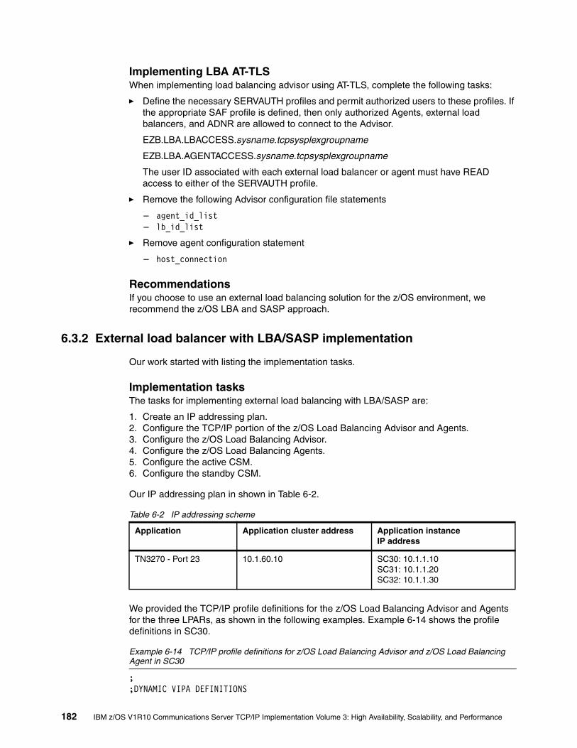
Implementing LBA AT-TLSWhen implementing load balancing advisor using AT-TLS, complete the following tasks:
� Define the necessary SERVAUTH profiles and permit authorized users to these profiles. If the appropriate SAF profile is defined, then only authorized Agents, external load balancers, and ADNR are allowed to connect to the Advisor.
EZB.LBA.LBACCESS.sysname.tcpsysplexgroupname
EZB.LBA.AGENTACCESS.sysname.tcpsysplexgroupname
The user ID associated with each external load balancer or agent must have READ access to either of the SERVAUTH profile.
� Remove the following Advisor configuration file statements
– agent_id_list – lb_id_list
� Remove agent configuration statement
– host_connection
RecommendationsIf you choose to use an external load balancing solution for the z/OS environment, we recommend the z/OS LBA and SASP approach.
6.3.2 External load balancer with LBA/SASP implementation
Our work started with listing the implementation tasks.
Implementation tasksThe tasks for implementing external load balancing with LBA/SASP are:
1. Create an IP addressing plan.2. Configure the TCP/IP portion of the z/OS Load Balancing Advisor and Agents.3. Configure the z/OS Load Balancing Advisor.4. Configure the z/OS Load Balancing Agents.5. Configure the active CSM.6. Configure the standby CSM.
Our IP addressing plan in shown in Table 6-2.
Table 6-2 IP addressing scheme
We provided the TCP/IP profile definitions for the z/OS Load Balancing Advisor and Agents for the three LPARs, as shown in the following examples. Example 6-14 shows the profile definitions in SC30.
Example 6-14 TCP/IP profile definitions for z/OS Load Balancing Advisor and z/OS Load Balancing Agent in SC30
; ;DYNAMIC VIPA DEFINITIONS
Application Application cluster address Application instanceIP address
TN3270 - Port 23 10.1.60.10 SC30: 10.1.1.10SC31: 10.1.1.20SC32: 10.1.1.30
182 IBM z/OS V1R10 Communications Server TCP/IP Implementation Volume 3: High Availability, Scalability, and Performance

; VIPADYNAMIC VIPADEFINE MOVEABLE IMMEDIATE 255.255.255.0 10.1.8.10VIPADISTribute DISTMethod SERVERWLM 10.1.8.10 PORT 23 DESTIP 10.1.7.31 10.1.7.21 10.1.7.11 VIPAROUTE 10.1.7.31 10.1.1.30 VIPAROUTE 10.1.7.21 10.1.1.20 VIPAROUTE 10.1.7.11 10.1.1.10 VIPARANGE 255.255.255.0 10.1.9.0ENDVIPADYNAMIC
AUTOLOG 5 LBADV ; SASP Load Balancing Advisor LBAGENT ; SASP Load Balancing Agent
PORT 3860 TCP LBADV ; SASP Workload Advisor (LB connections) 8100 TCP LBADV ; SASP Workload Advisor (Agent connections) 8000 TCP LBAGENT NOAUTOLOG 1 ; SASP Workload Agent (Advisor connection)
Example 6-15 shows the profile definitions for SC31.
Example 6-15 TCP/IP profile definitions for z/OS Load Balancing Advisor and z/OS Load Balancing Agent in SC31
; ;DYNAMIC VIPA DEFINITIONS; VIPADYNAMIC VIPADEFine MOVEable IMMEDiate 255.255.255.0 10.1.8.20VIPADISTRIBUTE DISTMETHOD SERVERWLM 10.1.8.20 PORT 23 DESTIP 10.1.7.31 10.1.7.21 10.1.7.11 VIPAROUTE 10.1.7.31 10.1.1.30 VIPAROUTE 10.1.7.21 10.1.1.20 VIPAROUTE 10.1.7.11 10.1.1.10 VIPARANGE 255.255.255.0 10.1.9.0 ENDVIPADYNAMIC
AUTOLOG 5 LBAGENT
PORT 3860 TCP LBADV ; SASP Workload Advisor (LB connections) 8100 TCP LBADV ; SASP Workload Advisor (Agent connections) 8000 TCP LBAGENT NOAUTOLOG 1 ; SASP Workload Agent (Advisor connection)
Example 6-16 shows the profile definitions for SC32.
Example 6-16 TCP/IP profile definitions for z/OS Load Balancing Advisor and z/OS Load Balancing Agent in SC32
VIPADYNAMICVIPADEFine MOVEable IMMEDiate 255.255.255.0 10.1.8.30 VIPADISTribute DISTMethod SERVERWLM 10.1.8.30
Chapter 6. External application workload balancing 183

PORT 80 23 DESTIP 10.1.7.31 10.1.7.21 10.1.7.11 VIPARANGE 255.255.255.0 10.1.9.0ENDVIPADYNAMIC AUTOLOG 5 LBAGENT ; SASP Load Balancing Agent
PORT 3860 TCP LBADV ; SASP Workload Advisor (LB connections) 8100 TCP LBADV ; SASP Workload Advisor (Agent connections) 8000 TCP LBAGENT NOAUTOLOG 1 ; SASP Workload Agent (Advisor connection)
Note that 1 NOAUTOLOG must be coded on the port definition if we use AUTOLOG to start the LBAGENT.
We configured the z/OS Load Balancing Advisor as shown in Example 6-17. (The z/OS Load Balancing Advisor configuration file is specified on the CONFIG DD statement in the advisor start procedure.)
Example 6-17 Configuration file for z/OS Load Balancing Advisor
debug_level 7 update_interval 60 agent_connection_port 8100 1 agent_id_list { 10.1.1.10..8000 2 10.1.1.20..8000 10.1.1.30..8000# ::1..8000 } lb_connection_v4 10.1.9.30..3860 3 lb_id_list lb_id_list { 10.1.60.2 4
10.1.60.3 5# ::1 } wlm serverwlm 6 port_list { 23 { wlm serverwlm } 8000 { wlm serverwlm }
184 IBM z/OS V1R10 Communications Server TCP/IP Implementation Volume 3: High Availability, Scalability, and Performance

8100 { wlm serverwlm } }
The following key elements are in this configuration are:
1. Port 8100 is used to receive connections from LBAGENTs.
2. This is the list of valid LBAGENTs that can connect to this z/OS Load Balancing Advisor.
3. z/OS Load Balancing Advisor binds to this IP address and listens on specified port.
4. This is the IP address of the active load balancer.
5. This is the IP address of the standby load balancer.
6. Serverwlm weights will be the default.
We configured the z/OS Load Balancing Agents in each LPAR. Example 6-18 shows the configuration file for SC30. (The z/OS Load Balancing Agent configuration file is specified on the CONFIG DD statement in the start procedure.)
Example 6-18 Configuration file for z/OS Load Balancing Agent in SC30
debug_level 7 advisor_id 10.1.9.30..8100 1
host_connection 10.1.1.10..8000 2
Example 6-19 shows the configuration file for SC31.
Example 6-19 Configuration file for z/OS Load Balancing Agent in SC31
debug_level 7 advisor_id 10.1.9.30..8100 1
host_connection 10.1.1.20..8000 2
Example 6-20 shows the configuration file for SC32.
Example 6-20 Configuration file for z/OS Load Balancing Agent in SC32
debug_level 7 advisor_id 10.1.9.30..8100 1
host_connection 10.1.1.30..8000 2
Note that 1 LBAGENT connects to the z/OS Load Balancing Advisor by this IP address and port, and 2 LBAGENT uses this as the source IP address and port.
Chapter 6. External application workload balancing 185

We configured the active CSM as shown in Example 6-21.
Example 6-21 Configuration for active CSM
module ContentSwitchingModule 2 1 variable ROUTE_UNKNOWN_FLOW_PKTS 1 variable SASP_CSM_UNIQUE_ID CSM-6509A 2! ft group 61 vlan 61 3 priority 101! vlan 60 server 4ip address 10.1.60.2 255.255.255.0 route 0.0.0.0 0.0.0.0 gateway 10.1.60.240 alias 10.1.60.1 255.255.255.255! probe PING-30S icmp 5 interval 30 retries 2 failed 30! real SC30-TN3270 6 address 10.1.1.10 inservice real SC31-TN3270 address 10.1.1.20 inservice real SC32-TN3270 address 10.1.1.30 inservice! serverfarm TN3270 7 nat server no nat client bindid 65521 real name SC30-TN3270 inservice real name SC31-TN3270 inservice real name SC32-TN3270 inservice! vserver TN3270 8 virtual 10.1.60.10 tcp telnet serverfarm TN3270 replicate csrp connection persistent rebalance inservice! dfp agent 10.1.9.30 3860 65521 9!interface Vlan10 10 ip address 10.1.2.240 255.255.255.0 ip policy route-map pbr-to-csm!
186 IBM z/OS V1R10 Communications Server TCP/IP Implementation Volume 3: High Availability, Scalability, and Performance

interface Vlan60 11 description VLAN 60 for CSM ip address 10.1.60.240 255.255.255.0 ip ospf cost 5!interface Vlan61 12 description CSM Failover no ip address!router ospf 100 13 router-id 10.1.3.240 log-adjacency-changes area 2 stub no-summary network 10.1.2.0 0.0.0.255 area 2 network 10.1.3.0 0.0.0.255 area 2 network 10.1.100.0 0.0.0.255 area 2 network 10.1.0.0 0.0.255.255 area 0 network 10.200.1.0 0.0.0.255 area 0 default-information originate always metric-type 1!ip access-list extended tn3270 14 permit tcp host 10.1.1.30 eq telnet any permit tcp host 10.1.1.20 eq telnet any permit tcp host 10.1.1.10 eq telnet any!route-map pbr-to-csm permit 10 15 match ip address tn3270 set ip next-hop 10.1.60.1!
The following elements are important:
1. CSM is in module 2 of this switch.
2. Unique ID for active CSM required.
3. Fault tolerance uses dedicated VLAN 61.
4. CSM server VLAN. Subnet 10.1.60.0/24. This is the subnet for CSM and application clusters. There is no routing within the CSM, only static routes pointing to the routers.
5. This is the ICMP probe used for polling a given application instance for availability.
6. This is the real server definition pointing to the static VIPA per LPAR.
7. This is the server farm definition grouping real servers together and probe indicating polling of each real server. If a real server refuses to answer, the real server is marked unavailable.
8. This is the virtual server representing the application cluster. Replicate csrp connection implements stateful failover between the CSMs without connection loss of existing connections.
9. This is the DFP agent pointing to z/OS Load Balancing Advisor.
10.VLAN 10. Subnet 10.1.2.0/24. This is the OSA-Express Gigabit Ethernet attachment of z/OS. Policy-based routing is enabled in this VLAN.
11.VLAN 60. Subnet 10.1.60.0/24.This is the subnet for CSM and application clusters.
12.VLAN 61.This is the dedicated VLAN for CSM failover services.
Chapter 6. External application workload balancing 187

13.OSPF process 100 includes subnets matching 10.1.0.0/16.
14.This is the extended access list used by policy-based routing.
15.This is the Route Map used by policy-based routing. It ensures that datagrams from extended access list TN3270 are being forwarded back to the CSM.
We configured the standby CSM as shown in Example 6-22.
Example 6-22 Configuration for standby CSM
module ContentSwitchingModule 3 1 variable ROUTE_UNKNOWN_FLOW_PKTS 1variable SASP_CSM_UNIQUE_ID CSM-6509B 2! ft group 61 vlan 61 3 priority 100! vlan 60 server 4 ip address 10.1.60.3 255.255.255.0 route 0.0.0.0 0.0.0.0 gateway 10.30.60.4 route 0.0.0.0 0.0.0.0 gateway 10.30.60.5 alias 10.1.60.1 255.255.255.255! probe PING-30S icmp 5 interval 30 retries 2 failed 30! real SC30-TN3270 6 address 10.1.1.10 inservice real SC31-TN3270 address 10.1.1.20 inservice real SC32-TN3270 address 10.1.1.30 inservice real TN3270-SC30 inservice! serverfarm TN3270 7 nat server no nat client real name SC30-TN3270 inservice real name SC31-TN3270 inservice real name SC32-TN3270 inservice probe PING-30S! vserver TN3270 8 virtual 10.1.60.10 tcp telnet serverfarm TN3270 replicate csrp connection persistent rebalance
188 IBM z/OS V1R10 Communications Server TCP/IP Implementation Volume 3: High Availability, Scalability, and Performance

inservice!dfp 9 agent 10.1.9.31 3860 65520!interface Vlan11 10 ip address 10.1.3.11 255.255.255.0 ip policy route-map pbr-to-csm!interface Vlan60 11 description VLAN 60 for CSM ip address 10.1.60.241 255.255.255.0 ip ospf cost 5!interface Vlan61 12 description CSM Failover no ip address!router ospf 100 13 router-id 10.1.2.220 log-adjacency-changes area 1 stub no-summary network 10.30.0.0 0.0.255.255 area 1!ip access-list extended tn3270 14 permit tcp host 10.1.1.30 eq telnet any permit tcp host 10.1.1.20 eq telnet any permit tcp host 10.1.1.10 eq telnet any!!route-map pbr-to-csm permit 10 15 match ip address tn3270 set ip next-hop 10.1.60.1!
Some elements are slightly different than used with the active CSM:
1. CSM is in module 3 of this switch.
2. Unique ID for active CSM required.
3. Fault tolerance uses dedicated VLAN 61.
4. CSM server VLAN. Subnet 10.1.60.0/24. This is the subnet for CSM and application clusters. There is no routing within the CSM, only static routes pointing to the routers.
5. This is the ICMP probe used for polling a given application instance for availability.
6. This is the real server definition pointing to the static VIPA per LPAR.
7. This is the server farm definition grouping real servers together and probe indicating polling of each real server. If a real server refuses to answer the real server is marked unavailable.
8. This is the virtual server representing the application cluster. Replicate csrp connection implements stateful failover between the CSMs without connection loss of existing connections.
9. This is the DFP agent pointing to z/OS Load Balancing Advisor.
10.VLAN 11. Subnet 10.1.3.0/24. This is the OSA-Express Gigabit Ethernet attachment of z/OS. Policy-based routing is enabled in this VLAN.
Chapter 6. External application workload balancing 189

11.VLAN 60. Subnet 10.1.60.0/24. This is the subnet for CSM and application clusters.
12.VLAN 61.This is the dedicated VLAN for CSM failover services.
13.OSPF process 100 includes subnets matching 10.30.0.0/16.
14.This is the extended access list used by policy-based routing.
15.This is the Route Map used by policy-based routing. It ensures that datagrams from extended access list TN3270 are being forwarded back to the CSM.
VerificationWe verified correct operation by using the following steps:
1. We started the Load Balancing Advisor.
2. We started the Load Balancing Agent in all three LPARs.
3. We checked the connections between the agents and the switch units.
4. We checked the status of the DFP agents in CSM.
5. We verified that the Data Facility Product (DFP) agents in CSM had registered with an z/OS Load Balancing Advisor.
6. We verified that application members registered with the agents.
7. We connected 12 TN3270 clients.
8. We observed what happens if one TCP/IP stack is lost.
9. We observed what happens if an agent is lost.
10.We observed what happens if the z/OS Load Balancing Advisor is lost.
We started the z/OS Load Balancing Advisor in SC30. Example 6-23 shows the LB Advisor is ready.
Example 6-23 LB Advisor is listening ready and listening
D TCPIP,TCPIPA,N,CONN,PORT=3860 EZD0101I NETSTAT CS V1R9 TCPIPA 730USER ID CONN STATE LBADV 00000022 LISTEN LOCAL SOCKET: 10.1.9.30..3860 FOREIGN SOCKET: 0.0.0.0..0 LBADV 00000036 ESTBLSH LOCAL SOCKET: 10.1.9.30..3860 FOREIGN SOCKET: 10.1.60.2..4364 2 OF 2 RECORDS DISPLAYED
Example 6-24 shows the joblog.
Example 6-24 z/OS Load Balancing Advisor joblog
LBADV STARTED LBADV STARTING LBADV INITIALIZATION COMPLETE LBADV AGENT CONNECTED FROM ::FFFF:10.1.1.10 LBADV LOAD BALANCER CONNECTED FROM 10.1.60.2 LBADV AGENT CONNECTED FROM ::FFFF:10.1.1.30 LBADV AGENT CONNECTED FROM ::FFFF:10.1.1.20
The agents started in all three LPARs, as shown in Example 6-25.
190 IBM z/OS V1R10 Communications Server TCP/IP Implementation Volume 3: High Availability, Scalability, and Performance

Example 6-25 LB Agent joblog in SC30, SC31, and SC32
$HASP373 LBAGENT STARTED EZD1231I LBAGENT STARTING EZD1232I LBAGENT INITIALIZATION COMPLETE EZD1259I LBAGENT CONNECTED TO ADVISOR 10.1.9.30
We verified that the agents were connected to the advisor. Example 6-26 shows the connection in SC30.
Example 6-26 z/OS Load Balancing Advisor connection in SC30
D TCPIP,TCPIPA,N,CONN,PORT=8000 EZD0101I NETSTAT CS V1R9 TCPIPA USER ID CONN STATE LBADV 000001CD ESTBLSH LOCAL SOCKET: ::FFFF:10.1.9.30..8100 FOREIGN SOCKET: ::FFFF:10.1.1.20..8000LBADV 00000033 ESTBLSH LOCAL SOCKET: ::FFFF:10.1.9.30..8100 FOREIGN SOCKET: ::FFFF:10.1.1.10..8000LBADV 0000004B ESTBLSH LOCAL SOCKET: ::FFFF:10.1.9.30..8100 FOREIGN SOCKET: ::FFFF:10.1.1.30..8000LBAGENT 00000032 ESTBLSH LOCAL SOCKET: 10.1.1.10..8000 FOREIGN SOCKET: 10.1.9.30..8100 4 OF 4 RECORDS DISPLAYED
Example 6-27 shows the connection in SC31.
Example 6-27 z/OS Load Balancing Advisor connection in SC31
D TCPIP,TCPIPB,N,CONN,PORT=8000 EZD0101I NETSTAT CS V1R9 TCPIPB USER ID CONN STATE LBAGENT 00000052 ESTBLSH LOCAL SOCKET: 10.1.1.20..8000 FOREIGN SOCKET: 10.1.9.30..8100 1 OF 1 RECORDS DISPLAYED
Example 6-28 shows the connection in SC32.
Example 6-28 z/OS Load Balancing Advisor connection in SC32
D TCPIP,TCPIPC,N,CONN,PORT=8000 EZD0101I NETSTAT CS V1R9 TCPIPC 298USER ID CONN STATE LBAGENT 00000054 ESTBLSH LOCAL SOCKET: 10.1.1.30..8000 FOREIGN SOCKET: 10.1.9.30..8100 1 OF 1 RECORDS DISPLAYED
Chapter 6. External application workload balancing 191

We checked the connections from the LBA connection on the LPAR running the advisor, as shown in Example 6-29.
Example 6-29 z/OS Load Balancing Advisor connections in SC30
LBADV 000001CD ESTBLSH LOCAL SOCKET: ::FFFF:10.1.9.30..8100 FOREIGN SOCKET: ::FFFF:10.1.1.20..8000 1LBADV 00000033 ESTBLSH LOCAL SOCKET: ::FFFF:10.1.9.30..8100 FOREIGN SOCKET: ::FFFF:10.1.1.10..8000 2LBADV 0000004B ESTBLSH LOCAL SOCKET: ::FFFF:10.1.9.30..8100 FOREIGN SOCKET: ::FFFF:10.1.1.30..8000 3LBADV 00000022 LISTEN LOCAL SOCKET: 10.1.9.30..3860 4 FOREIGN SOCKET: 0.0.0.0..0 LBADV 00000036 ESTBLSH LOCAL SOCKET: 10.1.9.30..3860 FOREIGN SOCKET: 10.1.60.2..4364 5LBAGENT 00000032 ESTBLSH LOCAL SOCKET: 10.1.1.10..8000 6 FOREIGN SOCKET: 10.1.9.30..8100 LBADV 00000024 LISTEN LOCAL SOCKET: ::..8100 7 FOREIGN SOCKET: ::..0
Relevant points in this display are:
1. The z/OS Load Balancing Agent from SC31.
2. The z/OS Load Balancing Agent from SC30.
3. The z/OS Load Balancing Agent from SC32.
4. The z/OS Load Balancing Advisor listener socket - SASP clients.
5. The z/OS Load Balancing Advisor connection from active CSM.
6. The z/OS Load Balancing Advisor listener socket - z/OS Load Balancing Agents.
7. The z/OS Load Balancing Agent connection with z/OS Load Balancing Advisor.
We checked the status of the DFP agents in the active CSM, as shown in Example 6-30.
Example 6-30 DFP Agent display in active CSM
Router# sh mod csm 2 dfp detailRouter1>sh mod csm 2 dfp detailDFP Agent 10.1.9.30:3860 Connection state: Connected 1 Keepalive = 65521 Retry Count = 0 Interval = 180 (Default) Security errors = 0 Last message received: 14:59:44 est 09/21/07 Last reported Real weights for Protocol TCP, Port telnet Host 10.1.1.10 Bind ID 65521 Weight 1 Host 10.1.1.20 Bind ID 65521 Weight 1 Host 10.1.1.30 Bind ID 65521 Weight 1
DFP manager listen port not configured.No weights to report to managers.
192 IBM z/OS V1R10 Communications Server TCP/IP Implementation Volume 3: High Availability, Scalability, and Performance

Router#
Note that 1 the DFP agent in active CSM is connected with the z/OS Load Balancing Advisor.
We also checked the status of the standby CSM agent, as shown in Example 6-31.
Example 6-31 DFP Agent display in standby CSM
Router#sh mod csm 3 dfp detailDFP Agent 10.1.9.31:3860 Connection state: Connected 1 Keepalive = 65520 Retry Count = 0 Interval = 180 (Default) Security errors = 0 Last message received: 14:59:55 est 09/21/07 Last reported Real weights for Protocol TCP, Port telnet Host 10.1.1.10 Bind ID 65520 Weight 2 Host 10.1.1.20 Bind ID 65520 Weight 1 Host 10.1.1.30 Bind ID 65520 Weight 1
DFP manager listen port not configured.No weights to report to managers.Router#
Note that 1 the DFP agent in the standby CSM is connected with the z/OS Load Balancing Advisor.
We verified that the DFP agents in CSM had registered with the z/OS Load Balancing Advisor in SC30, as shown in Example 6-32.
Example 6-32 Display a load balancer summary
F LBADV,DISP,LB EZD1242I LOAD BALANCER SUMMARY 994 LB INDEX : 00 UUID : 436973636F2D43534D2D3635303941 IPADDR..PORT : 10.1.60.2..4364 HEALTH : 7E FLAGS : NOCHANGE PUSH 1 OF 1 RECORDS DISPLAYED
We displayed a detailed list of the data registered with the active CSM under index 00, as shown in Example 6-33. (The LB index numbers are shown in Example 6-32.)
Example 6-33 Display load balancer details about active CSM
F LBADV,DISP,LB,I=00EZD1243I LOAD BALANCER DETAILS 999 LB INDEX : 00 UUID : 436973636F2D43534D2D3635303941 IPADDR..PORT : 10.1.60.2..4364 HEALTH : 7E FLAGS : NOCHANGE PUSH GROUP NAME : TN3270 GROUP FLAGS : SERVERWLM IPADDR..PORT: 10.1.1.30..23 SYSTEM NAME: SC32 PROTOCOL : TCP AVAIL : YES WLM WEIGHT : 00064 CS WEIGHT : 100 NET WEIGHT: 00001 1 RAW CP: 64 ZAAP: 00 ZIIP: 00 PROPORTIONAL CP: 64 ZAAP: 00 ZIIP: 00 ABNORM : 00000 HEALTH : 100 FLAGS : IPADDR..PORT: 10.1.1.20..23
Chapter 6. External application workload balancing 193

SYSTEM NAME: SC31 PROTOCOL : TCP AVAIL : YES WLM WEIGHT : 00064 CS WEIGHT : 100 NET WEIGHT: 00001 1 RAW CP: 64 ZAAP: 00 ZIIP: 00 PROPORTIONAL CP: 64 ZAAP: 00 ZIIP: 00 ABNORM : 00000 HEALTH : 100 FLAGS : IPADDR..PORT: 10.1.1.10..23 SYSTEM NAME: SC30 PROTOCOL : TCP AVAIL : YES WLM WEIGHT : 00064 CS WEIGHT : 100 NET WEIGHT: 00001 1 RAW CP: 64 ZAAP: 00 ZIIP: 00 PROPORTIONAL CP: 64 ZAAP: 00 ZIIP: 00
ABNORM : 00000 HEALTH : 100 FLAGS : 3 OF 3 RECORDS DISPLAYED
Note the 1 WLM weight, Communications Server weight, and NET weight (the weight that is forwarded to the external load balancer).
The load balancer details displayed in Example 6-34 are also available from the CSM. Remember that the z/OS Load Balancing Advisor sends the NET WEIGHT to the CSM and to the standby CSM.
Example 6-34 Display dfp weights in active CSM
Router# sh mod csm 2 dfp weightsReal IP : 10.1.1.10 Protocol: TCP Port: telnet Bind_ID: 65521 Weight: 1 1Set by Agent 10.1.9.30:3860 at 01:13:47 est 09/21/07
Real IP : 10.1.1.20 Protocol: TCP Port: telnet Bind_ID: 65521 Weight: 1 1Set by Agent 10.1.9.30:3860 at 02:15:20 est 09/21/07
Real IP : 10.1.1.30 Protocol: TCP Port: telnet Bind_ID: 65521 Weight: 1 1Set by Agent 10.1.9.30:3860 at 01:15:30 est 09/21/07Router#
Note 1 the NET weight received from the z/OS Load Balancing Advisor.
We used the command shown in the following examples to verify the members registered in the agents in each LPAR. Example 6-35 shows the member details in SC30.
Example 6-35 LBAGENT member details in SC30
F LBAGENT,DISP,MEM,DET EZD1245I MEMBER DETAILS 009 LB INDEX : 00 UUID : 436973636F2D43534D2D3635303941 GROUP NAME : TN3270 IPADDR..PORT: 10.1.1.10..23 TCPNAME : TCPIPA MATCHES : 001 PROTOCOL : TCP FLAGS : ANY JOBNAME : TN3270A ASID : 00A0 RESOURCE : 00000028 1 OF 1 RECORDS DISPLAYED
Example 6-36 shows the member details in SC31.
Example 6-36 LBAGENT member details in SC31
F LBAGENT,DISP,MEM,DET
194 IBM z/OS V1R10 Communications Server TCP/IP Implementation Volume 3: High Availability, Scalability, and Performance
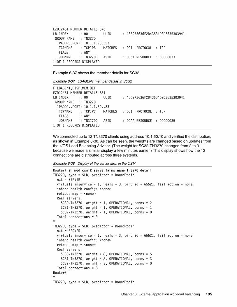
EZD1245I MEMBER DETAILS 646 LB INDEX : 00 UUID : 436973636F2D43534D2D3635303941 GROUP NAME : TN3270 IPADDR..PORT: 10.1.1.20..23 TCPNAME : TCPIPB MATCHES : 001 PROTOCOL : TCP FLAGS : ANY JOBNAME : TN3270B ASID : 006A RESOURCE : 00000033 1 OF 1 RECORDS DISPLAYED
Example 6-37 shows the member details for SC32.
Example 6-37 LBAGENT member details in SC32
F LBAGENT,DISP,MEM,DET EZD1245I MEMBER DETAILS 881 LB INDEX : 00 UUID : 436973636F2D43534D2D3635303941 GROUP NAME : TN3270 IPADDR..PORT: 10.1.1.30..23 TCPNAME : TCPIPC MATCHES : 001 PROTOCOL : TCP FLAGS : ANY JOBNAME : TN3270C ASID : 00AA RESOURCE : 00000035 1 OF 1 RECORDS DISPLAYED
We connected up to 12 TN3270 clients using address 10.1.60.10 and verified the distribution, as shown in Example 6-38. As can be seen, the weights are changed based on updates from the z/OS Load Balancing Advisor. (The weight for SC32-TN3270 changed from 2 to 3 because we made a similar display a few minutes earlier.) This display shows how the 12 connections are distributed across three systems.
Example 6-38 Display of the server farm in the CSM
Router# sh mod csm 2 serverfarms name tn3270 detailTN3270, type = SLB, predictor = RoundRobin nat = SERVER virtuals inservice = 1, reals = 3, bind id = 65521, fail action = none inband health config: <none> retcode map = <none> Real servers: SC30-TN3270, weight = 1, OPERATIONAL, conns = 2 SC31-TN3270, weight = 1, OPERATIONAL, conns = 1 SC32-TN3270, weight = 1, OPERATIONAL, conns = 0 Total connections = 3*TN3270, type = SLB, predictor = RoundRobin nat = SERVER virtuals inservice = 1, reals = 3, bind id = 65521, fail action = none inband health config: <none> retcode map = <none> Real servers: SC30-TN3270, weight = 8, OPERATIONAL, conns = 5 SC31-TN3270, weight = 8, OPERATIONAL, conns = 3 SC32-TN3270, weight = 3, OPERATIONAL, conns = 0 Total connections = 8Router#*TN3270, type = SLB, predictor = RoundRobin
Chapter 6. External application workload balancing 195

nat = SERVER virtuals inservice = 1, reals = 3, bind id = 65521, fail action = none inband health config: <none> retcode map = <none> Real servers: SC30-TN3270, weight = 8, OPERATIONAL, conns = 5 SC31-TN3270, weight = 8, OPERATIONAL, conns = 4 SC32-TN3270, weight = 3, OPERATIONAL, conns = 1 Total connections = 10*TN3270, type = SLB, predictor = RoundRobin nat = SERVER virtuals inservice = 1, reals = 3, bind id = 65521, fail action = none inband health config: <none> retcode map = <none> Real servers: SC30-TN3270, weight = 8, OPERATIONAL, conns = 6 1 SC31-TN3270, weight = 8, OPERATIONAL, conns = 5 1 SC32-TN3270, weight = 3, OPERATIONAL, conns = 1 1 Total connections = 12
Note that 1 the 12 TN3270 connections are now distributed according to the weights send by the agents.
We then stopped the TCP/IP stack in SC32, making the TN3270 server in SC32 unavailable. This broke TN3270 sessions. When we reconnected the sessions, they were distributed according to the weights in the remaining TN3270 servers, as shown in Example 6-39. This display shows how the 12 connections are distributed across two systems.
Note that the weighting recommendations can change rapidly during a recovery situation such as this and slightly different reconnection timings could produce slightly different connection distributions.
Example 6-39 Display of the server farm in the CSM
Router# sh mod csm 2 serverfarms name tn3270 detailTN3270, type = SLB, predictor = RoundRobin nat = SERVER virtuals inservice = 1, reals = 3, bind id = 65521, fail action = none inband health config: <none> retcode map = <none> Real servers: SC30-TN3270, weight = 1, OPERATIONAL, conns = 7 SC31-TN3270, weight = 1, OPERATIONAL, conns = 5 SC32-TN3270, weight = 0, DFP_THROTTLED, conns = 0 1 Total connections = 12Router#
Note that 1 real server SC32-TN3270 has the status DFP_THROTTLED.
After stopping the TCP/IP stack (and the TN3270 server) on SC32, the advisor assigns a weight of zero, as shown in Example 6-40. The zero weight means “Do not forward requests to this server instance.”
196 IBM z/OS V1R10 Communications Server TCP/IP Implementation Volume 3: High Availability, Scalability, and Performance

Example 6-40 Display load balancer details about active CSM
F LBADV,DISP,LB,I=00 EZD1243I LOAD BALANCER DETAILS 303 LB INDEX : 00 UUID : 436973636F2D43534D2D3635303941 IPADDR..PORT : 10.1.60.2..4364 HEALTH : 7E FLAGS : NOCHANGE PUSH GROUP NAME : TN3270 GROUP FLAGS : SERVERWLM IPADDR..PORT: 10.1.1.30..23 SYSTEM NAME: N/A PROTOCOL : TCP AVAIL : NO WLM WEIGHT : 00000 CS WEIGHT : 000 NET WEIGHT: 00000 1 RAW CP: 64 ZAAP: 00 ZIIP: 00 PROPORTIONAL CP: 64 ZAAP: 00 ZIIP: 00 ABNORM : 00000 HEALTH : 100 FLAGS : NOTARGETSYS 2 IPADDR..PORT: 10.1.1.20..23 SYSTEM NAME: SC31 PROTOCOL : TCP AVAIL : YES WLM WEIGHT : 00064 CS WEIGHT : 100 NET WEIGHT: 00001 RAW CP: 64 ZAAP: 00 ZIIP: 00 PROPORTIONAL CP: 64 ZAAP: 00 ZIIP: 00 ABNORM : 00000 HEALTH : 100 FLAGS : IPADDR..PORT: 10.1.1.10..23 SYSTEM NAME: SC30 PROTOCOL : TCP AVAIL : YES WLM WEIGHT : 00064 CS WEIGHT : 100 NET WEIGHT: 00001 RAW CP: 64 ZAAP: 00 ZIIP: 00 PROPORTIONAL CP: 64 ZAAP: 00 ZIIP: 00
ABNORM : 00000 HEALTH : 100 FLAGS : 3 OF 3 RECORDS DISPLAYED
Note that 1 weights changed to zero, indicating that the application instance is not ready for connections. Also note that 2 LBQ says that the load balancer has quiesced the member. NOTARGETSYS says that the z/OS Load Balancing Advisor will advise the load balancer that the application instance should not receive new workload.
If an agent is down, existing sessions to the LPAR continue, but new sessions are not sent to that LPAR. In Example 6-41 we stopped the z/OS Load Balancing Agent in SC32.
Example 6-41 Display of the server farm in the CSM shows how the 12 connections are distributed
Router# sh mod csm 2 serverfarms name tn3270 detailTN3270, type = SLB, predictor = RoundRobin nat = SERVER virtuals inservice = 1, reals = 3, bind id = 65521, inband health config: <none> retcode map = <none> Real servers: SC30-TN3270, weight = 1, OPERATIONAL, conns = 7 SC31-TN3270, weight = 1, OPERATIONAL, conns = 5 SC32-TN3270, weight = 0, DFP_THROTTLED, conns = 0 1 Total connections = 12Router#
Chapter 6. External application workload balancing 197

1. Real server SC32-TN3270 has the status DFP_THROTTLED and weight zero, which means that new connections will not be sent.
We experimented by taking down the z/OS Load Balancing Advisor. The display in Example 6-42 illustrates this state. When the retry limit (10) is reached, the CSM returns to its internal load-balancing algorithm (round-robin) until the z/OS Load Balancing Advisor is back. Existing connections continue without disruption.
Example 6-42 Connection from DFP fails
Router#sh mod csm 2 dfp detailDFP Agent 10.1.9.30:3860 Connection state: Failed Retries: 2 1 Keepalive = 65521 Retry Count = 0 Interval = 180 (Default) Security errors = 0 Last message received: 18:37:20 est 09/21/07 Last reported Real weights for Protocol TCP, Port telnet Host 10.1.1.10 Bind ID 65521 Weight 1 Host 10.1.1.20 Bind ID 65521 Weight 1 Host 10.1.1.30 Bind ID 65521 Weight 1
DFP manager listen port not configured.No weights to report to managers.Router#
Note that the 1 DFP connection to the z/OS Load Balancing Advisor has failed. It will be retried 10 times.
After all the retries fail, the CSM uses its default internal balancing, which is round-robin, as shown in Example 6-43. The equal weights of 8 indicate that the CSM is doing its round-robin balancing.
Example 6-43 Display of the server farm in the CSM shows how the 12 connections are distributed
Router#sh mod csm 2 serverfarms name tn3270 detailTN3270, type = SLB, predictor = RoundRobin nat = SERVER virtuals inservice = 1, reals = 3, bind id = 65521, fail action = none inband health config: <none> retcode map = <none> Real servers: SC30-TN3270, weight = 1, OPERATIONAL, conns = 6 1 SC31-TN3270, weight = 1, OPERATIONAL, conns = 5 1 SC32-TN3270, weight = 1, OPERATIONAL, conns = 0 1 Total connections = 11
Router#
1. The external load balancer returns to internal decision-making (round-robin).
198 IBM z/OS V1R10 Communications Server TCP/IP Implementation Volume 3: High Availability, Scalability, and Performance

Problem determinationWe approached problem determination for this example in the following order:
1. Check that application instances are running in z/OS (active listener).2. Check that there is connectivity between the router and z/OS.3. Check that the real server is operational.4. Check that the virtual server is operational.5. Check for connectivity between client and CSM (application cluster address=vserver
address).6. Check that policy-based routing definitions are in place.7. Run packet trace.8. Run CTRACE.9. Use a network analyzer.10.Run debug in the external networking devices.11.Run debug in z/OS Load Balancing Advisor, z/OS Load Balancing Agents, or both.
Both the z/OS Load Balancing Advisor and the z/OS Load Balancing Agents can write logs to the syslogd daemon facility. To use this, syslogd must be started before starting the z/OS Load Balancing Advisor and the z/OS Load Balancing Agent. The debug level (7) should normally be used unless problem documentation needs to be gathered. Increased levels of debug can result in excessive amounts of information.
Logging levels for the advisor and agent are:
0 None. No debug messages are logged. 1 Error-level messages are logged. 2 Warning-level messages are logged. 4 Event-level messages are logged. 8 Info-level messages are logged. 16 Message-level messages are logged. These are details of the messages (packets)
sent between the advisor and LB, and the advisor and agent. 32 Collection-level messages are logged. These are details of the collection and
manipulation of data supporting the calculated weights. This level only has meaning to the Agent. The Advisor does not log any data at this level.
64 Debug-level messages are logged. These are internal debug messages intended for development and service.
128 Trace-level messages are logged. These are function entry and exit traces that show the path through the code.
To log a combination of debug levels, add the debug level numbers. The default debug level is 7, which captures all error, warning, and event messages.
Note: Server (application)-specific WLM weights are supported in z/OS V1R7 (and later). The CSM registers application-specific members, provided that each vserver utilizes separate server farms; otherwise, the CSM only registers system members.
In the last example, the z/OS Load Balancing Advisor used SERVERWLM. Using SERVERWLM usually results in better workload distribution.
Be aware that TN3270 is part of the TCP/IP stack in our example. By using SERVERWLM for TN3270, we actually receive WLM recommendations for the TCP/IP stack and not TN3270 itself. We recommend that you use SERVERWLM for servers running in their own address spaces, such as an HTTP server.
Chapter 6. External application workload balancing 199

200 IBM z/OS V1R10 Communications Server TCP/IP Implementation Volume 3: High Availability, Scalability, and Performance

Chapter 7. Intra-sysplex workload balancing
Previous chapters described internal and external application workload balancing methods. These techniques were based on accessing an application server through one cluster IP address by the client.
In a multitier application environment, however, the path between the different application servers within the sysplex might become long, resulting in a performance impact. This can occur, for example, when an HTTP server, a WebSphere Application Server, and an Enterprise Information System (EIS) such as IMS or CICS® are involved in a single client connection request. In such situations, optimized paths within the sysplex can provide better performance.
In this chapter you will find several examples that illustrate how multitier application support can improve existing workload balancing solutions.
This chapter discusses the following topics.
7
Section Topic
7.1, “Optimizing SD intra-sysplex load balancing” on page 202”
Basic goals needed to optimize intra-sysplex application server workload balancing in a multitier environment
7.2, “Optimized multitier z/OS SD load balancing” on page 205
Implementation of several optimized multitier load balancing solutions with Sysplex Distributor and external load balancer
7.3, “WLM reporting abnormal conditions” on page 231
Basics of WLM weight calculation and the use of abnormal conditions detected by WLM to reduce weight recommendations
© Copyright IBM Corp. 2009. All rights reserved. 201

7.1 Optimizing SD intra-sysplex load balancing
In a multitier application environment, there are situations where connection requests can cross logical partitions (LPARs) before reaching the appropriate application instance. The selection of a server that is on a different LPAR than the client is initiated through workload balancing decision units such as Sysplex Distributor. Figure 7-1 illustrates a typical configuration where an LPAR crossing occurs.
Figure 7-1 Local and remote connections
This configuration shows two load balancing decision points:
� An external load balancer, which uses Workload Manager (WLM) recommendations from the z/OS Load Balancing Advisor (LBA)
� A Sysplex Distributor
This example is also valid if you use Sysplex Distributor only. A backup Sysplex Distributor is not shown in this figure.
7.1.1 Current connections from WebSphere Application Server to EIS
There are two types of connectors for WebSphere Application Server-to-EIS communication. They are depicted in Figure 7-1 as a local connection (1) and as remote connections (2) and (3).
Note: This example is not unique to a WebSphere Application Server environment. Any z/OS sysplex multitier application environment might exhibit similar behavior and have similar issues.
External Load Balancer
EISWAS
z/OS LBA
LPAR1 LPAR2
Sysplex Distributor
CS
EISWAS1
3
CS
2
202 IBM z/OS V1R10 Communications Server TCP/IP Implementation Volume 3: High Availability, Scalability, and Performance

Local connection (1)Connection requests coming from a client through the external load balancer will arrive at the TCP/IP stack and are then forwarded directly to the WebSphere Application Server. From there, the client requests are forwarded to Enterprise Information Systems (EIS) through a connector. An EIS can be a system such as CICS, IMS, or DB2.
Local connections provide an optimized, high-speed path (see (1) in Figure 7-1) based on local services such as cross-memory services.
Problems will appear if the local target (for example, the EIS) is not available. Because local connections are used, there is no way to switch to an alternate target in a different LPAR. Also, because the WebSphere Application Server transactions are failing, they will appear to complete quickly with little CPU usage, thus causing the Workload Manager (WLM) to prefer that LPAR (in our example, LPAR1) for increased workload. This situation is known as a storm drain issue.
Remote connection (2) and (3)WebSphere Application Server uses remote connections for a connection to the EIS. These are TCP connections. A load balancer decides which address to use as the connection endpoint for the EIS (in our example, in LPAR1 or LPAR2), and this decision is based on WLM recommendations. In our case, it is the Sysplex Distributor that selects a target among available targets defined in the sysplex.
If the target is local and the Sysplex Distributor is remote (as shown in Figure 7-1 in LPAR2 using the (2) path), or if the target is remote (in LPAR2 using the (3) path), the communication path is not as efficient as when it remains in one LPAR.
The solution to this problem should include the following aspects:
� Automatically locating a target server in the same LPAR as the client
� Favoring that local target as long as it is available and has sufficient capacity for new work based on WLM recommendations
� No longer favoring the local target if these conditions are not met
The overall goal of the improved multitier application support should be an optimized path to the application servers with better performance and without losing high availability.
Chapter 7. Intra-sysplex workload balancing 203

7.1.2 Optimized multitier application workload balancing
Figure 7-2 illustrates a multitier application environment.
Figure 7-2 Multitier application configuration
In Figure 7-2, two LPARs have the same server applications, and they consist of the following elements:
� An HTTP proxy server, which receives TCP requests from clients’ browsers through an external load balancer
The external load balancer has WLM information provided by the z/OS Load Balancing Advisor (LBA) regarding which HTTP server in LPAR1 or in LPAR2 would best perform. This information is used by the load balancer to select the HTTP server in LPAR1 or LPAR2. In our example, the decision was made to send the HTTP request to the TCP/IP stack in LPAR1.
If no external load balancer is used, then the Sysplex Distributor would be the first address of the client request on LPAR1 that could be used to select the HTTP server instead.
� The WebSphere Application Server, which receives TCP requests from the HTTP server
This TCP request is controlled by the Sysplex Distributor only. The Sysplex Distributor controls the selection of the HTTP server by defining distributed dynamic VIPAs. However, if the Sysplex Distributor decides to send the HTTP request to a WebSphere Application Server in another LPAR, then the communication overhead would rise.
The best performance can be achieved by using a fast direct local sockets path to the WebSphere Application Server, which belongs to the same TCP/IP stack as the HTTP server. With this function, the selection of a local server and connection setup can stay
EIS
W AS
HTTP
z/O S LBA
LPA R1
EIS
W AS
HTTP
LPA R2
Sysplex D istributor
Sysplex D istribu tor SD
Sysplex D istribu tor SD
SA SP
W LM LPAR and server-specific perfo rm ance we ightsTC P/IP stack server-specific hea lth weights
externa l Load Balancer
connection request
Sysplex D istributor
optim izedh igh perform ance pa th
Backup path
Backup path
204 IBM z/OS V1R10 Communications Server TCP/IP Implementation Volume 3: High Availability, Scalability, and Performance

within the local LPAR even if the distributor is remote. When both client and selected server are local, the data path will use fast direct local sockets.
By using application endpoint awareness with the enhanced sysplex sockets API, security functions such as authentication overhead and data conversions can be avoided because the connection’s setup and datapath is local.
When configuring the Sysplex Distributor to use optimized load balancing, you can determine the level of preference for local targets, as explained here:
� Always choose a local target if that target is available and healthy.
� Compare WLM weights after applying a multiplier to the local target weight to determine if the local target should be preferred.
The user controls this function by defining the OPTLOCAL statement on the VIPADISTRIBUTE statement.
7.2 Optimized multitier z/OS SD load balancing
This section explains some basic concepts, and then describes the configuration we used. It also explains the flow of client requests to the WebSphere Application Server and EIS, and examines our test cases, which consisted of different multitier solutions.
7.2.1 Basic concepts and general information
Optimized multitier z/OS load balancing can be achieved in two ways:
� By using sysplex external load balancing (see Chapter 6, “External application workload balancing” on page 159), plus sysplex internal load balancing such as Sysplex Distributor (see Chapter 5, “Internal application workload balancing” on page 95)
� By using sysplex internal load balancing only through Sysplex Distributor (see Chapter 5, “Internal application workload balancing” on page 95)
In our test environment, we used the second solution. This solution differs only in that the Sysplex Distributor (instead of the external load balancer) decides which HHTP server in LPAR1 (SC30) or LPAR2 (SC31) receives the TCP SYN request, and that decision is based on the best WLM value.
Chapter 7. Intra-sysplex workload balancing 205

Note that in order to switch on optimized load balancing, an additional parameter (OPTLOCAL) must be defined in the VIPADISTRIBUTE statement, as illustrated in Figure 7-3.
Figure 7-3 OPTLOCAL parameter in a VIPADISTRIBUTE statement
The OPTLOCAL keyword allows the client to bypass sending the connection request to the Sysplex Distributor.
Three sets of values influence the conditions in which the connection will remain local:
� A value of 0 indicates that the connection should always remain local.
� A value of 1 indicates that the connection should remain local unless the server’s WLM weight is zero (0).
� Values of 2 - 16 are used as multipliers to increase the local WLM weight to favor the local stack.
Regardless of the value specified, the connection request will always be sent to the Sysplex Distributor if any of the following situations occur:
� No server application is available on the local stack.
� The Server Efficiency Fraction (SEF) value on the local stack is less than 75. A SEF value of 100 is the best value.
SEF is influenced through monitoring the target server by the stack. This value is based on whether new connections are being established—and after being established, whether the server is accepting new connections.
� The health indicator for the local stack is less than 75 (available only for applications that provide this information to WLM using the IWM4HLTH or IWMSRSRG services).
The health indicator provides a general health indication for an application or subsystem. Under normal circumstances, the value of this field is 100, meaning the server is 100% healthy. Any value less than 100 indicates that the server is experiencing problem conditions that are not allowing it to process new work requests successfully. A value of less than 100 also causes the WLM to reduce the recommendation provided to the Sysplex Distributor for this server instance.
VIPASMparms VIPAROUTE VIPADISTribute
VIPADISTribute:
Options: (These can be specified in any order) :
> TIMEDAFFinity seconds
TIMEDAFFinity 0
SYSPLEXPorts
DEFINE
DELEte
VIPADISTribute Options ipv4_addr
ipv6_interface
>
> OPTLOCAL
NOOPTLOCAL DISTMethod BASEWLM
DISTMethod ROUNDROBIN
SERVERWLM
1
value
206 IBM z/OS V1R10 Communications Server TCP/IP Implementation Volume 3: High Availability, Scalability, and Performance

� The abnormal transactions count for the local stack is greater than 250.
A non-zero value indicates that the server application has reported abnormal transaction completions to WLM, and that WLM has reduced the server-specific recommendation for this server instance. The higher the value of this field, the greater the reduction in the recommendation provided by WLM.
For more information regarding the conditions leading to abnormal transaction completions for a given server application, refer to the documentation provided by the server application.
OPTLOCAL is intended to be used mainly in context with DISTMETHOD SERVERWLM or DISTMETHOD BASEWLM. If ROUNDROBIN is used together with OPTLOCAL, then the OPTLOCAL value must be zero (0), because WLM weights are not being collected. If another value is defined, then the EZD1231I message will indicate that the OPTLOCAL value is set to zero (0).
7.2.2 Applied system configuration for optimized load balancing
We used the configuration shown in Figure 7-4 on page 208 for our test scenarios. It consisted of two LPARs (SC30 and SC31). Each LPAR was configured with one TCP/IP stack. The primary Sysplex Distributor was in SC30, and a backup Sysplex Distributor was in the SC31 stack. In order to built a multitier application scenario testing the VIPADISTRIBUTE OPTLOCAL keyword, on each stack we installed one HTTP proxy server and a WebSphere Application Server with deployment manager.
The HTTP proxy server was defined as distributed DVIPA with IP cluster address 10.30.30.33 and port 80 for the Sysplex Distributor. The WebSphere Application Server with its built-in HTTP server got the distributed DVIPA cluster address 10.30.30.34 with port 28538. We also had to define additional port numbers for the WebSphere Application Server environment (deployment manager, control region, and so on).
To keep the test scenario simple, we did not use an EIS (such as IMS, DB2 or CICS). Instead, we used a special test application called StockTrade provided by the WebSphere Application Server implementation packet.
We used two kinds of HTTP connection setup requests:
� From a workstation 10.12.4.198 with MS® Internet Explorer® (see Figure 7-6)� Through a WebSphere Workload Simulator
Chapter 7. Intra-sysplex workload balancing 207

Figure 7-4 Multitier optimized load balancing test environment
TCP/IP profile definitions for SC30 and SC31The definitions in Example 7-1 and Example 7-2 only show specific VIPADYNAMIC statements. OPTLOCAL 0 is defined for IP address 10.30.30.34, with different ports for WebSphere Application Server applications. This definition forces the selection of the WebSphere Application Server built-in HTTP server in the same LPAR as the HTTP proxy server as long as it is healthy.
The HTTP proxy server gets the client connection requests forwarded from the Sysplex Distributor. It does not need the OPTLOCAL keyword.
Example 7-1 shows the VIPADYNAMIC definitions for the SC30 primary Sysplex Distributor.
Example 7-1 VIPADYNAMIC definitions for SC30 primary Sysplex Distributor
VIPADynamic VIPADEFine MOVEable IMMEDiate 255.255.255.0 10.30.30.32 VIPADISTribute DISTMethod BASEWLM 10.30.30.32 PORT 23 20 21 DESTIP 10.30.20.100 10.30.20.101 10.30.20.102 VIPADEFine MOVEable IMMEDiate 255.255.255.0 10.30.30.33 VIPADISTribute DISTMethod SERVERWLM 10.30.30.33 PORT 80 DESTIP 10.30.20.100 10.30.20.101 VIPADEFine MOVEable IMMEDiate 255.255.255.0 10.30.30.34 VIPADISTribute DISTMethod SERVERWLM 10.30.30.34 OPTLOCAL 0
PORT 28538 28518 28510 28502 28503 DESTIP 10.30.20.100 10.30.20.101
Sysplexgroup EZBTCPCS
Switch/Router
connection request
SC30
Sysplex Distributor
Appl
WASbuilt-inHTTPServer
HTTPProxy-ServerDVIPA 10.30.30.33
Port 80
VIPA 10.30.1.230
SC31
Appl
WASbuilt-inHTTPServer
HTTPProxy-Server
VIPA 10.30.1.242
DVIPA 10.30.30.34Port 28538
DVIPA 10.30.30.33Port 80
DVIPA 10.30.30.34Port 28538
BackupSysplex Distributor
10.12.4.0
DXCF 10.30.20.100 DXCF 10.30.20.101
208 IBM z/OS V1R10 Communications Server TCP/IP Implementation Volume 3: High Availability, Scalability, and Performance

Example 7-2 shows the VIPADYNAMIC definitions for the SC31 backup Sysplex Distributor.
Example 7-2 VIPADYNAMIC definitions for SC31 backup Sysplex Distributor
VIPADynamic VIPABACKUP 100 MOVEABLE IMMEDIATE 255.255.255.0 10.30.30.32 10.30.30.33 10.30.30.34 VIPADISTribute define DISTMethod BASEWLM 10.30.30.32 PORT 23 20 21 DESTIP 10.30.20.100 10.30.20.101 10.30.20.102 VIPADISTribute define DISTMethod SERVERWLM 10.30.30.33 PORT 80 DESTIP 10.30.20.100 10.30.20.101 VIPADISTribute define DISTMethod SERVERWLM OPTLOCAL 0 10.30.30.34 PORT 28538 28518 28510 28502 28503 DESTIP 10.30.20.100 10.30.20.101 VIPAROUTE 10.30.20.100 10.30.1.230 VIPAROUTE 10.30.20.101 10.30.1.242 VIPAROUTE 10.30.20.102 10.30.1.221 ENDVIPADynamic
7.2.3 Request flow between client, WebSphere Application Server and application endpoint
Figure 7-5 shows the data flow from a client to the WebSphere Application Server application with the URL StockTrade/CPUBound.
Figure 7-5 HTTP request flow
Sysplexgroup EZBTCPCS
Switch/Router
connection request
SC30
Sysplex Distributor
Appl
WASbuilt-inHTTPServer
HTTPProxy-ServerDVIPA 10.30.30.33
Port 80
VIPA 10.30.1.230
SC31
Appl
WASbuilt-inHTTPServer
HTTPProxy-Server
VIPA 10.30.1.242
DVIPA 10.30.30.34Port 28538
DVIPA 10.30.30.33Port 80
DVIPA 10.30.30.34Port 28538
BackupSysplex Distributor
9.12.4.0
DXCF 10.30.20.100 DXCF 10.30.20.101
1
2
3
4
7
5
6
10
8
Client
9
Chapter 7. Intra-sysplex workload balancing 209

The steps in the HTTP request flow, as depicted in the figure, are explained here:
1. The user enters an initial request with URL StockTrade/CPUBound in the client browser. The request has no session affinity.
2. The request is resolved to a cluster IP address (10.30.30.33) and port address (80), and is sent to the primary Sysplex Distributor running in SC30 (or to the backup Sysplex Distributor SC31, if the primary is down).
3. The Sysplex Distributor makes its load balancing decision based on the best server-specific WLM values for the HTTP proxy servers on SC30 and SC31. It forwards the client request to the selected HTTP server. Both HTTP servers are configured with plug-in configuration file of the WebSphere Application Server (plug-in-cfg.xml file).
4. The configuration files describes which URLs are handled by WebSphere Application Server. In our case, it is the application StockTrade, which can be reached through the distributed DVIPA cluster address 10.30.30.34 and port 28538, in WebSphere Application Server on SC30 and SC31.
The application runs on both target systems SC30 and SC31. The plug-in checks for possible session affinity by scanning the request for session cookies. The first request has no affinity. The plug-in recognizes the URL /StockTrade/CPUBound, and routes it to the IP cluster address 10.30.3034 with port 28538, based on:
– The DVIPA address of the Sysplex Distributor forwarding it to WebSphere Application Server on SC30 or SC31 based on best SERVERWLM values if no OPTLOCAL keyword was defined.
– Directly to the WebSphere Application Server in the local system if OPTLOCAL 0 was defined (see Figure 7-3 on page 206).
– Directly to the WebSphere Application Server in the local system if OPTLOCAL 1 (see Figure 7-3 on page 206) was defined and sufficient capacity is provided by the local WebSphere Application Server. If the SERVERWLM values are zero (0), then the Sysplex Distributor is involved to search for a better WebSphere Application Server in the sysplex group to reach the WLM goal.
The HTTP listener on port 28538 in the WebSphere Application Server receives the request. There is no session affinity at this time. The session ID will be created later when the destination application builds a session object with a session ID. Later on, a session cookie is added to the HTTP data stream in the response to the client.
5. The response with the jsessionID cookie in the HTTP header is sent back to the Web server (in our case, to the HTTP proxy server in the system where the request came from).
6. The response is sent back to the client.
7. The browser stores the cookie in its memory. (Session cookies are never stored on a disk.) The cookie stays there as long as the browser is not closed, or until it is deleted (because of expiration) by the server.
8. The cookie is appended to the HTTP request at the next request to the server.
9. The Sysplex Distributor does not consider any session affinity. Therefore, there is no cookie check and the request could be sent to a different HTTP server.
10.The plug-in scans the HTTP header of the request and finds the session ID cookie with an additional CloneID. It compares this CloneID with its definition in the plug-in configuration (plug-in-cfg.xml) file. If there is a match, the request is sent to the IP address and port of the matched application server instance.
For more details about WebSphere Application Server session handling, refer to Architecting High Availability Using WebSphere V6 on z/OS, SG24-6850.
210 IBM z/OS V1R10 Communications Server TCP/IP Implementation Volume 3: High Availability, Scalability, and Performance

Figure 7-6 depicts a browser connection request to an HTTP proxy server, which is sent to the Sysplex Distributor. In this case, the Sysplex Distributor sent the request to the HTTP server on system SC31 where the server with its job name BWSR02B was started.
Figure 7-6 Web browser connection to HTTP server in SC31
Another request was directed to the HTTP server on system SC30 with its job name BWSR01A (see Figure 7-7).
Figure 7-7 Web browser connection to HTTP server in SC30
7.2.4 OPTLOCAL test cases
In this section, we discuss the use of the OPTLOCAL keyword in conjunction with Sysplex Distributor and an external load balancer that supports Server Application State Protocol (SASP). Figure 7-4 on page 208 describes our configuration with the needed IP and port addresses of the components that we used.
Optimized path through SD, using OPTLOCAL 0The goal here is to show the impact of the keyword OPTLOCAL 0 in the VIPADISTRIBUTE statement for WebSphere Application Server only. Figure 7-8 shows the optimized path between client and the Web application. Because the Sysplex Distributor has two choices, the optimized path can be created in SC30 or SC31, between the HTTP server and WebSphere Application Server.
Chapter 7. Intra-sysplex workload balancing 211

Figure 7-8 Optimized path through OPTLOCAL 0
TCP/IP profile definitionsExample 7-3 shows the TCP/IP profile definitions we used in our environment.
Example 7-3 VIPADYNAMIC definitions
VIPADEFine/VIPADISTRIBUTE VIPADynamic VIPADEFine MOVEable IMMEDiate 255.255.255.0 10.30.30.32 VIPADISTribute DISTMethod BASEWLM 10.30.30.32 PORT 23 20 21 DESTIP 10.30.20.100 10.30.20.101 10.30.20.102 VIPADEFine MOVEable IMMEDiate 255.255.255.0 10.30.30.33 VIPADISTribute DISTMethod SERVERWLM 10.30.30.33 PORT 80 DESTIP 10.30.20.100 10.30.20.101 VIPADEFine MOVEable IMMEDiate 255.255.255.0 10.30.30.34 VIPADISTribute DISTMethod SERVERWLM OPTLOCAL 0 10.30.30.34 PORT 28538 28518 28510 28502 28503 DESTIP 10.30.20.100 10.30.20.101 VIPAROUTE 10.30.20.100 10.30.1.230 VIPAROUTE 10.30.20.101 10.30.1.242 VIPAROUTE 10.30.20.102 10.30.1.221ENDVIPADYNAMIC
connection requestsfrom workstations
EIS
HTTP
SC31
WASOPTLOCAL 0
VIPA 10.30.1.242
DVIPA 10.30.30.34Port 28538
DVIPA 10.30.30.33Port 80
EIS
HTTP
SC30
Sysplex Distributor
WASOPTLOCAL 0
DVIPA 10.30.30.33Port 80
VIPA 10.30.1.230
DVIPA 10.30.30.34Port 28538
DXCF 10.30.20.100 DXCF 10.30.20.101
load balancing
optimized path optimized path
Connection requests from WebSphere Studio workload simulator
Switch/Router
212 IBM z/OS V1R10 Communications Server TCP/IP Implementation Volume 3: High Availability, Scalability, and Performance

Verification, diagnosisExample 7-4 points to the flag that displays if OPTLOCAL is switched on for IP address 10.30.30.34 and port address 28538 of WebSphere Application Server. In our case, it is defined as SERVERWLM and OPTLOCAL 0.
Example 7-4 netstat vipadcfg shows the OPTLOCAL definitions
D TCPIP,TCPIPC,N,VIPADCFG,DETAIL
DYNAMIC VIPA INFORMATION: VIPA DEFINE: IPADDR/PREFIXLEN: 10.30.30.34/24 MOVEABLE: IMMEDIATE SRVMGR: NO
DEST: 10.30.30.34..28538 DESTXCF: 10.30.20.100 SYSPT: NO TIMAFF: NO FLG: SERVERWLM OPTLOCAL OPTLOC: 0 DEST: 10.30.30.34..28538 DESTXCF: 10.30.20.101 SYSPT: NO TIMAFF: NO FLG: SERVERWLM OPTLOCAL OPTLOC: 0
Client requests from the Web browser are directed to the WebSphere Application Server application (see Figure 7-6 on page 211) on SC30 or SC31. Other client requests are initiated through the WebSphere Studio workload simulator and also directed to the WebSphere Application Server on SC30 or SC31.
The netstat conn command shown in Figure 7-5 indicates that the HTTP proxy server on SC31 with the name WEBBW311 received connections from a client with an IP address 10.30.2.50. This is the WebSphere Studio workload simulator we used to produce client connection requests.
Example 7-5 Current connection check of HTTP server on SC31
D TCPIP,TCPIPC,N,CONN,IPPORT=10.30.30.33+80
USER ID CONN STATE WEBBW311 0000A6C2 ESTBLSH LOCAL SOCKET: 10.30.30.33..80 FOREIGN SOCKET: 10.30.2.50..3255 WEBBW311 0000A6C4 ESTBLSH LOCAL SOCKET: 10.30.30.33..80 FOREIGN SOCKET: 10.30.2.50..3256 WEBBW311 0000A6C6 ESTBLSH LOCAL SOCKET: 10.30.30.33..80 FOREIGN SOCKET: 10.30.2.50..3257
In regard to the current HTTP TCP connections of the HTTP servers, you will notice that those connections will disappear at some point in time. This is due to the HTTP architecture, which allows the server to close the connections because they are no longer needed. The HTTP server (working as a client), starts a new connection to the WebSphere Application Server built-in HTTP server to forward the client request. Also notice the data flow described in 7.2.3, “Request flow between client, WebSphere Application Server and application endpoint” on page 209.
Chapter 7. Intra-sysplex workload balancing 213

Example 7-6 shows the VIPA distribution port table used in the sysplex for SC30 and SC31. It also depicts how many connections the Sysplex Distributor forwarded to the two HTTP servers using a load balancing service. Because OPTLOCAL 0 was defined, we assume that the depicted TOTALCONN number came from the local HTTP server identified through the DESTXCF address, for example, for 10.30.20.100. This is the address of the TCP/IP stack in SC30. Equivalent values are shown for the second HTTP server on SC31.
Thus, 89 connections came to the HTTP proxy server on SC30 and 157 to SC31. For each request, the HTTP server started a new connection to IP address 10.30.30.34. and port address 28538 (of the WebSphere Application Server). The local connections in the same LPAR, however, are separated from each other in the sysplex.
Example 7-6 VIPA distribution port table for the WebSphere Application Server
D TCPIP,TCPIPC,N,VDPT,DETAIL,IPPORT=10.30.30.34+28538
DYNAMIC VIPA DESTINATION PORT TABLE: DEST: 10.30.30.34..28538 DESTXCF: 10.30.20.100 TOTALCONN: 0000000089 RDY: 001 WLM: 08 TSR: 100 FLG: SERVERWLM, LOCAL TCSR: 100 CER: 100 SEF: 100 ABNORM: 0000 HEALTH: 100 ACTCONN: 0000000005 QOSPLCACT: *DEFAULT* W/Q: 08 DEST: 10.30.30.34..28538 DESTXCF: 10.30.20.101 TOTALCONN: 0000000157 RDY: 001 WLM: 16 TSR: 100 FLG: SERVERWLM, LOCAL TCSR: 100 CER: 100 SEF: 100 ABNORM: 0000 HEALTH: 100 ACTCONN: 0000000009 QOSPLCACT: *DEFAULT* W/Q: 16 2 OF 2 RECORDS DISPLAYED END OF THE REPORT
You might wonder why the server WLM values in each system are different with 08 and 16. The proportion of the TOTALCONN values are also a 1:2 ratio. If both LPARs would have been defined equally regarding resources such as logical CPU, storage, and so on, then the number of distributed requests would be nearly equal. We later found out that SC31 used four CPUs and SC30 was defined with two CPUs only.
This 1:2 ratio can also be recognized in Figure 7-7 when showing the VIPA distribution table of the HTTP servers with the cluster address of 10.30.30.33 and port address of 80 on both systems. The TOTALCONN values have nearly a 1:2 ratio. 1
Example 7-7 VIPA distribution port table
D TCPIP,TCPIPC,N,VDPT,DETAIL,IPPORT=10.30.30.33+80
DYNAMIC VIPA DESTINATION PORT TABLE: DEST: 10.30.30.33..80 DESTXCF: 10.30.20.100 TOTALCONN: 0000001496 RDY: 001 WLM: 08 TSR: 100 1 FLG: SERVERWLM
214 IBM z/OS V1R10 Communications Server TCP/IP Implementation Volume 3: High Availability, Scalability, and Performance

TCSR: 100 CER: 100 SEF: 100 ABNORM: 0000 HEALTH: 100 ACTCONN: 0000000000 QOSPLCACT: *DEFAULT* W/Q: 08 DEST: 10.30.30.33..80 DESTXCF: 10.30.20.101 TOTALCONN: 0000002863 RDY: 001 WLM: 16 TSR: 100 1 FLG: SERVERWLM TCSR: 100 CER: 100 SEF: 100 ABNORM: 0000 HEALTH: 100 ACTCONN: 0000000008 QOSPLCACT: *DEFAULT* W/Q: 16 2 OF 2 RECORDS DISPLAYED END OF THE REPORT
The netstat conn command shown in Example 7-5 on page 213 also indicates that the HTTP proxy server on SC31 with the name WEBBW311 receives connections from a client with an IP address 10.30.2.50. This is the WebSphere Studio workload simulator we used to produce client connection requests.
One WebSphere Application Server is downWhen the WebSphere Application Server service goes down, shown in Example 7-8 on page 215, the output value from the netstat vdpt detail command shows RDY: 000 (1), instead of RDY: 001(2), whereas the value determines how many servers are ready, active, and listening.
Example 7-8 One WebSphere application server is down
D TCPIP,TCPIPC,N,VDPT,DETAIL,IPPORT=10.30.30.34+28538
DYNAMIC VIPA DESTINATION PORT TABLE: DEST: 10.30.30.34..28538 DESTXCF: 10.30.20.100 TOTALCONN: 0000000707 RDY: 000 WLM: 09 TSR: 100 1 3 FLG: SERVERWLM TCSR: 100 CER: 100 SEF: 100 ABNORM: 0000 HEALTH: 100 ACTCONN: 0000000000 QOSPLCACT: *DEFAULT* W/Q: 09 DEST: 10.30.30.34..28538 DESTXCF: 10.30.20.101 TOTALCONN: 0000002036 RDY: 001 WLM: 06 TSR: 100 2 3 FLG: SERVERWLM, LOCAL TCSR: 100 CER: 100 SEF: 100 ABNORM: 0000 HEALTH: 100 ACTCONN: 0000000984 QOSPLCACT: *DEFAULT* W/Q: 06 2 OF 2 RECORDS DISPLAYED END OF THE REPORT
Chapter 7. Intra-sysplex workload balancing 215

Further display commands show that the TOTALCONN 3 value does not increase, because the server is no longer being considered for new connections. The actual connection (ACTCONN) value for SC30 is always zero (0). The value for ACTCONN for the other member of the same HTTP cluster in SC31 shows different values.
Check whether both HTTP servers are activeExample 7-9 shows that the HTTP server on SC31 (10.30.30.33 with DESTXCF address 10.30.20.101) did not start correctly. Refer to 1 (RDY: 000 and WLM: 00).
Example 7-9 HTTP server check id active
D TCPIP,TCPIPC,N,VDPT,DETAIL,IPPORT=10.30.30.33+80
DYNAMIC VIPA DESTINATION PORT TABLE: DEST: 10.30.30.33..80 DESTXCF: 10.30.20.100 TOTALCONN: 0000000007 RDY: 001 WLM: 15 TSR: 100 FLG: SERVERWLM, LOCAL TCSR: 100 CER: 100 SEF: 100 ABNORM: 0000 HEALTH: 100 ACTCONN: 0000000000 QOSPLCACT: *DEFAULT* W/Q: 15 DEST: 10.30.30.33..80 DESTXCF: 10.30.20.101 TOTALCONN: 0000000000 RDY: 000 WLM: 00 TSR: 100 1 FLG: SERVERWLM TCSR: 100 CER: 100 SEF: 100 ABNORM: 0000 HEALTH: 100 ACTCONN: 0000000000 QOSPLCACT: *DEFAULT* W/Q: 00 2 OF 2 RECORDS DISPLAYED END OF THE REPORT
Extended NETSTAT command and displaysAdditional keywords of the netstat command allow more convenient operation. These keywords are explained here.
� The server keyword on the netstat ALL SERVER command can be used to filter out application servers in listen status, thus reducing the number of display lines; see Example 7-10.
Example 7-10 Command netstat all server in listen state
===> netstat all server Client Name: BWSR01A Client Id: 000091C6 Local Socket: 0.0.0.0..28538 Foreign Socket: 0.0.0.0..0 BytesIn: 00000000000000000000 BytesOut: 00000000000000000000 SegmentsIn: 00000000000000000000 SegmentsOut: 00000000000000000000 Last Touched: 15:29:30 State: Listen
RcvNxt: 0000000000 SndNxt: 0000000000 ClientRcvNxt: 0000000000 ClientSndNxt: 0000000000
216 IBM z/OS V1R10 Communications Server TCP/IP Implementation Volume 3: High Availability, Scalability, and Performance

InitRcvSeqNum: 0000000000 InitSndSeqNum: 0000000000 CongestionWindow: 0000000000 SlowStartThreshold: 0000000000 IncomingWindowNum: 0000000000 OutgoingWindowNum: 0000000000 SndWl1: 0000000000 SndWl2: 0000000000 SndWnd: 0000000000 MaxSndWnd: 0000000000 SndUna: 0000000000 rtt_seq: 0000000000 MaximumSegmentSize: 0000000536 DSField: 00
Round-trip information: Smooth trip time: 0.000 SmoothTripVariance: 1500.000
ReXmt: 0000000000 ReXmtCount: 0000000000 DupACKs: 0000000000 SockOpt: 8800 TcpTimer: 00 TcpSig: 00 TcpSel: 20 TcpDet: C0 TcpPol: 00 QOSPolicyRuleName: ReceiveBufferSize: 0000016384 SendBufferSize: 0000016384 ConnectionsIn: 0000000001 ConnectionsDropped: 0000000000 CurrentBacklog: 0000000000 MaximumBacklog: 0000000010 CurrentConnections: 0000000000 SEF: 100 Quiesced: No
� The keyword ipport on netstat ALL, CONN, ALLConn, SOCKets, TELnet, VDPT, and VCRT can be used to filter a specific server IP address plus port out of the huge display list.
OPTLOCAL with external load balancerThis configuration differs from the example discussed in “Optimized path through SD, using OPTLOCAL 0” on page 211 such that in this configuration, the distribution decision is not performed in the sysplex by the Sysplex Distributor. Instead, it is performed by an external load balancer such as Content Switching Module (CSM).
The external load balancer gets workload information for the balancing decision from the z/OS LBAdvisor. The LBAdvisor is informed about active and non-active application servers within the sysplex. System and server WLM information are provided by z/OS LBAgents in each LPAR. For further information about external load balancing, refer to Chapter 5, “Internal application workload balancing” on page 95.
Chapter 7. Intra-sysplex workload balancing 217

Figure 7-9 depicts the optimized path from the client to the application server.
Figure 7-9 Optimized path using external load balancer
As you see, no Sysplex Distributor is necessary for the distribution of connections to the HTTP server. The optimized high performance path starts at the HTTP server either in SC30 or SC31, regardless of whether an external load balancer or the Sysplex Distributor selected the HTTP server. This means that if the external load balancer decides to send the connection request directly to HTTP server in SC30, the same TCP/IP profile definitions for the path to the WebSphere Application Server can be used as defined and tested in “Optimized path through SD, using OPTLOCAL 0” on page 211.
TCP/IP profile definition for OPTLOCAL 0Example 7-11 TCP/IP profile definitions used in context with external load balancer
; VIPADEFine/VIPADISTRIBUTE VIPADynamic VIPADEFine MOVEable IMMEDiate 255.255.255.0 10.30.30.34 VIPADISTribute DISTMethod SERVERWLM OPTLOCAL 0 10.30.30.34
PORT 28538 28518 28510 28502 28503 DESTIP 10.30.20.100 10.30.20.101 ENDVIPADynamic
VerificationBecause nothing differs from “Verification, diagnosis” on page 213, we do not repeat the displays for the components in the sysplex.
A pp l
W A S
H T T P
z/O S LB A
LP A R 1
A pp l
W A S
H TT P
LP A R 2
S ysp lex D is trib u to r
S ysp lex D is tribu to r S D
S ysp lex D is tribu to r S D
S A S P
W LM L P A R and se rve r-spe c if ic p e rfo rm ance w e igh tsT C P /IP s tack se rve r-spe c ific he a lth w e igh ts
exte rna l Loa d B a lan ce r
co n nection requ es t
S ysp le x D is tribu to r
o p tim izedh igh pe rfo rm ance pa th
B ackup p a th
S ysp lex D is tribu to r S D
B ackup p a th
218 IBM z/OS V1R10 Communications Server TCP/IP Implementation Volume 3: High Availability, Scalability, and Performance

OPTLOCAL 1 with Sysplex Distributor onlyIn the previous test case using OPTLOCAL 0, only local connections should be used for the optimized path between the HTTP servers and the WebSphere Application Server, depending on which HTTP server was selected on SC30 or on SC31.
In this section, we discuss how the high availability path can be achieved automatically, even if the WLM values do not recommend taking the local connection when the value for the local server is zero (0).
Figure 7-10 shows additional paths to WebSphere Application Server server within the sysplex controlled by the Sysplex Distributor. If the local connections cannot be used because the WLM value for the WebSphere Application Server during connection setup indicates 00, then the Sysplex Distributor has to select another remote WebSphere Application Server within the sysplex.
Figure 7-10 Optimized path using OPTLOCAL 1
TCP/IP profile definitionsExample 7-12 shows the OPTLOCAL 1 definitions that we used for this test case.
Example 7-12 TCP/IP profile definitions using OPTLOCAL 1
VIPADynamic VIPADEFine MOVEable IMMEDiate 255.255.255.0 10.30.30.33 VIPADISTribute DISTMethod SERVERWLM 10.30.30.33 PORT 80 DESTIP 10.30.20.100 10.30.20.101 VIPADEFine MOVEable IMMEDiate 255.255.255.0 10.30.30.34 VIPADISTribute DISTMethod SERVERWLM optlocal 1 10.30.30.34 PORT 28538 28518 28510 28502 28503 DESTIP 10.30.20.100 10.30.20.101ENDVIPADYNAMIC
connection requestsfrom workstations
Appl
HTTP
SC31
WAS
VIPA 10.30.1.242
DVIPA 10.30.30.34Port 28538
DVIPA 10.30.30.33Port 80
Appl
HTTP
SC30
Sysplex Distributor
WASOPTLOCAL 1
DVIPA 10.30.30.33Port 80
VIPA 10.30.1.230
DVIPA 10.30.30.34Port 28538
DXCF 10.30.20.100 DXCF 10.30.20.101
load balancing
WLM = 00?
no
yes
optimized path
WLM = 00
?
nooptimized path
yes
OPTLOCAL 1
Switch/Router
Connection requests from WebSphere Studio workload simulator
Chapter 7. Intra-sysplex workload balancing 219

Verification We used the NETSTAT VIPADCFG DETAIL command to verify that the OPTLOCAL 1 was active (see Example 7-13).
Example 7-13 Netstat VIPADCFG detail
D TCPIP,TCPIPC,N,VIPADCFG,DETAIL
DYNAMIC VIPA INFORMATION: DEST: 10.30.30.34..28538 DESTXCF: 10.30.20.100 SYSPT: NO TIMAFF: NO FLG: SERVERWLM OPTLOCAL OPTLOC: 1 DEST: 10.30.30.34..28538 DESTXCF: 10.30.20.101 SYSPT: NO TIMAFF: NO FLG: SERVERWLM OPTLOCAL OPTLOC: 1
Example 7-14 shows the start of the WebSphere workload simulator and a check through netstat vdpt for the WebSphere Application Server. Notice that both WLM values are equal, but the number of total connections (TOTALCONN) differs slightly.
Example 7-14 Netstat VDPT of WebSphere Application Server using filter ipport
D TCPIP,TCPIPC,N,VDPT,DETAIL,IPPORT=10.30.30.34+28538
DYNAMIC VIPA DESTINATION PORT TABLE: DEST: 10.30.30.34..28538 DESTXCF: 10.30.20.100 TOTALCONN: 0000000318 RDY: 001 WLM: 06 TSR: 100 FLG: SERVERWLM, LOCAL TCSR: 100 CER: 100 SEF: 100 ABNORM: 0000 HEALTH: 100 ACTCONN: 0000000004 QOSPLCACT: *DEFAULT* W/Q: 06 DEST: 10.30.30.34..28538 DESTXCF: 10.30.20.101 TOTALCONN: 0000000258 RDY: 001 WLM: 06 TSR: 100 FLG: SERVERWLM, LOCAL TCSR: 100 CER: 100 SEF: 100 ABNORM: 0000 HEALTH: 100 ACTCONN: 0000000005 QOSPLCACT: *DEFAULT* W/Q: 06 2 OF 2 RECORDS DISPLAYED
After a few minutes, we issued netstat vdpt for WebSphere Application Server in order to obtain a second snapshot; see Example 7-15. Notice that the WLM values are no longer equal.
Example 7-15 Netstat VDPT again
D TCPIP,TCPIPC,N,VDPT,DETAIL,IPPORT=10.30.30.34+28538
DYNAMIC VIPA DESTINATION PORT TABLE:
220 IBM z/OS V1R10 Communications Server TCP/IP Implementation Volume 3: High Availability, Scalability, and Performance

DEST: 10.30.30.34..28538 DESTXCF: 10.30.20.100 TOTALCONN: 0000000428 RDY: 001 WLM: 08 TSR: 100 FLG: SERVERWLM, LOCAL TCSR: 100 CER: 100 SEF: 100 ABNORM: 0000 HEALTH: 100 ACTCONN: 0000000006 QOSPLCACT: *DEFAULT* W/Q: 08 DEST: 10.30.30.34..28538 DESTXCF: 10.30.20.101 TOTALCONN: 0000000359 RDY: 001 WLM: 11 TSR: 100 FLG: SERVERWLM, LOCAL TCSR: 100 CER: 100 SEF: 100 ABNORM: 0000 HEALTH: 100 ACTCONN: 0000000008 QOSPLCACT: *DEFAULT* W/Q: 11
After additional snapshots, we saw that the WLM values on both systems increased to 16, and that sometimes SC30 (10.30.20.100) had better WLM values, and other times SC31 (10.30.20.101) had better WLM values.
Takedown of the HTTP server on SC30Next, we purged the HTTP server address space in SC30 to check whether all connection requests go to HTTP server on SC31.
Example 7-16 shows that the RDY indicator is 000 (1), but WLM and other values do not indicate problems. So all connections do go to the HTTP server on SC31. This can be analyzed only through observing the TOTALCONN values in subsequent displays. The TOTALCONN value is frozen on 18880 (2) and the active connection count (ACTCONN) remains zero (0).
We noticed that the values for WLM, TSR, and so on remained the same, because no new calculations are done for a not ready server.
Example 7-16 After purging HTTP server address space
D TCPIP,TCPIPC,N,VDPT,DETAIL,IPPORT=10.30.30.33+80
DYNAMIC VIPA DESTINATION PORT TABLE: DEST: 10.30.30.33..80 DESTXCF: 10.30.20.100 TOTALCONN: 0000018880 2 RDY: 000 1 WLM: 13 TSR: 100 FLG: SERVERWLM TCSR: 100 CER: 100 SEF: 100 ABNORM: 0000 HEALTH: 100 ACTCONN: 0000000000 QOSPLCACT: *DEFAULT* W/Q: 13 DEST: 10.30.30.33..80 DESTXCF: 10.30.20.101 TOTALCONN: 0000017030 2 RDY: 001 WLM: 08 TSR: 100 FLG: SERVERWLM TCSR: 100 CER: 100 SEF: 100 ABNORM: 0000 HEALTH: 100
Chapter 7. Intra-sysplex workload balancing 221

ACTCONN: 0000000009 QOSPLCACT: *DEFAULT* W/Q: 08 2 OF 2 RECORDS DISPLAYED
Subsequent displays show the frozen TOTALCONN value of 18880 (1) in SC30 and that this value increased in SC31 from 17030 (2) to 21171 (3), and only the SC31 display indicates that there are active connections (ACTCONN); see Example 7-17.
Example 7-17 Frozen TOTALCONN in SC30
D TCPIP,TCPIPC,N,VDPT,DETAIL,IPPORT=10.30.30.33+80
DYNAMIC VIPA DESTINATION PORT TABLE: DEST: 10.30.30.33..80 DESTXCF: 10.30.20.100 TOTALCONN: 0000018880 1 RDY: 000 WLM: 13 TSR: 100 FLG: SERVERWLM TCSR: 100 CER: 100 SEF: 100 ABNORM: 0000 HEALTH: 100 ACTCONN: 0000000000 QOSPLCACT: *DEFAULT* W/Q: 13 DEST: 10.30.30.33..80 DESTXCF: 10.30.20.101 TOTALCONN: 0000021171 3 RDY: 001 WLM: 06 TSR: 100 FLG: SERVERWLM TCSR: 100 CER: 100 SEF: 100 ABNORM: 0000 HEALTH: 100 ACTCONN: 0000000010 QOSPLCACT: *DEFAULT* W/Q: 06 2 OF 2 RECORDS DISPLAYED
After a restart of the HTTP server on SC30, TOTALCONN (1) increased again from 18880 to 19772; see Example 7-18.
Example 7-18 Restart of HTTP server in system SC30
D TCPIP,TCPIPC,N,VDPT,DETAIL,IPPORT=10.30.30.33+80
DYNAMIC VIPA DESTINATION PORT TABLE: DEST: 10.30.30.33..80 DESTXCF: 10.30.20.100 TOTALCONN: 0000019772 1 RDY: 001 WLM: 12 TSR: 100 FLG: SERVERWLM TCSR: 100 CER: 100 SEF: 100 ABNORM: 0000 HEALTH: 100 ACTCONN: 0000000000 QOSPLCACT: *DEFAULT* W/Q: 12 DEST: 10.30.30.33..80 DESTXCF: 10.30.20.101 TOTALCONN: 0000024253 RDY: 001 WLM: 13 TSR: 100 FLG: SERVERWLM TCSR: 100 CER: 100 SEF: 100
222 IBM z/OS V1R10 Communications Server TCP/IP Implementation Volume 3: High Availability, Scalability, and Performance

ABNORM: 0000 HEALTH: 100 ACTCONN: 0000000011 QOSPLCACT: *DEFAULT* W/Q: 13 2 OF 2 RECORDS DISPLAYED
During takedown of the HTTP server on SC30, the Sysplex Distributor sent all connection requests to the HTTP server on SC31; see Example 7-19.
Example 7-19 Displays for the WebSphere Application Server during takedown phase of HTTP server on SC30
D TCPIP,TCPIPC,N,VDPT,DETAIL,IPPORT=10.30.30.34+28538
DYNAMIC VIPA DESTINATION PORT TABLE: DEST: 10.30.30.34..28538 DESTXCF: 10.30.20.100 TOTALCONN: 0000001990 1 RDY: 001 WLM: 07 TSR: 100 FLG: SERVERWLM, LOCAL TCSR: 100 CER: 100 SEF: 100 ABNORM: 0000 HEALTH: 100 ACTCONN: 0000000000 QOSPLCACT: *DEFAULT* W/Q: 07 DEST: 10.30.30.34..28538 DESTXCF: 10.30.20.101 TOTALCONN: 0000002587 RDY: 001 WLM: 06 TSR: 100 FLG: SERVERWLM, LOCAL TCSR: 100 CER: 100 SEF: 100 ABNORM: 0000 HEALTH: 100 ACTCONN: 0000000009 QOSPLCACT: *DEFAULT* W/Q: 06 2 OF 2 RECORDS DISPLAYED
Because the local connections optimized local path to the WebSphere Application Server takes effect, the TOTALCONN 1990 (1) value of the WebSphere Application Server display sequences on SC30 show that it is frozen. Only the value for SC31 increased; see Example 7-20.
Example 7-20 Second display in a sequence for the WebSphere Application Server
D TCPIP,TCPIPC,N,VDPT,DETAIL,IPPORT=10.30.30.34+28538
DYNAMIC VIPA DESTINATION PORT TABLE: DEST: 10.30.30.34..28538 DESTXCF: 10.30.20.100 TOTALCONN: 0000001990 1 RDY: 001 WLM: 08 TSR: 100 FLG: SERVERWLM, LOCAL TCSR: 100 CER: 100 SEF: 100 ABNORM: 0000 HEALTH: 100 ACTCONN: 0000000000 QOSPLCACT: *DEFAULT* W/Q: 08 DEST: 10.30.30.34..28538 DESTXCF: 10.30.20.101
Chapter 7. Intra-sysplex workload balancing 223

TOTALCONN: 0000002692 RDY: 001 WLM: 06 TSR: 100 FLG: SERVERWLM, LOCAL TCSR: 100 CER: 100 SEF: 100 ABNORM: 0000 HEALTH: 100 ACTCONN: 0000000010 QOSPLCACT: *DEFAULT* W/Q: 06 2 OF 2 RECORDS DISPLAYED
During takedown of the HTPP server on SC30, the optimized path with local path between the HTTP server and WebSphere Application Server instance on SC31 is used. No Sysplex Distributor was involved in the connection setup path between the HTTP server and WebSphere Application Server on SC31. This would only be necessary if the WLM value on SC31 would fall to the value of 00.
After a restart of the HTTP on SC30, the TOTALCONN increases; see Example 7-21.
Example 7-21 Restart HTTP server on SC30 - from WebSphere Application Server point of view
D TCPIP,TCPIPC,N,VDPT,DETAIL,IPPORT=10.30.30.34+28538
DYNAMIC VIPA DESTINATION PORT TABLE: DEST: 10.30.30.34..28538 DESTXCF: 10.30.20.100 TOTALCONN: 0000002028 RDY: 001 WLM: 07 TSR: 100 FLG: SERVERWLM, LOCAL TCSR: 100 CER: 100 SEF: 100 ABNORM: 0000 HEALTH: 100 ACTCONN: 0000000003 QOSPLCACT: *DEFAULT* W/Q: 07 DEST: 10.30.30.34..28538 DESTXCF: 10.30.20.101 TOTALCONN: 0000003070 RDY: 001 WLM: 07 TSR: 100 FLG: SERVERWLM, LOCAL TCSR: 100 CER: 100 SEF: 100 ABNORM: 0000 HEALTH: 100 ACTCONN: 0000000009 QOSPLCACT: *DEFAULT* W/Q: 07 2 OF 2 RECORDS DISPLAYED
Overloaded WebSphere Application Server server on SC30We drove the WebSphere Workload Simulator on SC30 with the WebSphere Application Server weight set to WLM = 000 to test whether the Sysplex Distributor would get control.
As shown in Example 7-22, the WLM value is 00 (1), and TSR (2) and SEF(3) values show 000 for the WebSphere Application Server instance.
Example 7-22 Overloaded WebSphere Application Server server on SC30
D TCPIP,TCPIPC,N,VDPT,DETAIL,IPPORT=10.30.30.34+28538
DYNAMIC VIPA DESTINATION PORT TABLE: DEST: 10.30.30.34..28538 DESTXCF: 10.30.20.100
224 IBM z/OS V1R10 Communications Server TCP/IP Implementation Volume 3: High Availability, Scalability, and Performance

TOTALCONN: 0000003491 RDY: 001 4 WLM: 00 1 TSR: 000 2 FLG: SERVERWLM TCSR: 100 5 CER: 100 6 SEF: 000 3 ABNORM: 0000 8 HEALTH: 100 7 ACTCONN: 0000000022 QOSPLCACT: *DEFAULT* W/Q: 00 DEST: 10.30.30.34..28538 DESTXCF: 10.30.20.101 TOTALCONN: 0000004646 RDY: 001 WLM: 06 TSR: 100 FLG: SERVERWLM, LOCAL TCSR: 100 CER: 100 SEF: 100 ABNORM: 0000 HEALTH: 100 ACTCONN: 0000000014 QOSPLCACT: *DEFAULT* W/Q: 06 2 OF 2 RECORDS DISPLAYED
The server efficiency fraction (SEF) 3 indicated that the WebSphere Application Server was unable to receive connection requests, because the application server queue is overloaded accepting new connection requests. The SEF value of 000 influences also caused the target server responsiveness (TSR) 2 value of zero (0). If the SEF value is under 075, all connection requests will be sent to the Sysplex Distributor to make the routing decision.
Other indicators (such as RDY, TSCR, CER, HEALTH, and abnorm) do not point to any problems.
� RDY = 001 (4) means the server (only one) is still running.
� TCSR (target connectivity success rate) = 100 (5) means that all connection requests sent by the distribution stack are received by the target stack. A low value could indicate a problem with the connection between the distribution and target stack.
� CER (connection establishment rate) = 100 (6) means that all connections can be established between the HTTP proxy server (in this case, working as a client) and the WebSphere Application Server built-in HTTP server. The problems in our case arose in the next step, when the built-in HTTP WebSphere Application Server did not accept the new connections.
� HEALTH (7) is an indicator for the specific server. The field affects the WLM weight and operation of the OPTLOCAL distributor setting. If this value is lower than 75, all connection requests will go to the Sysplex Distributor.
� abnorm (8) counts all abnormal ended transactions.
For example, a CICS server might work without any problems, but some transactions are in trouble because of very slow database access. Because all indicators for the CICS server show values with a favorable state, the Sysplex Distributor would continue sending new connection requests to the CICS server. Now the abnorm count is also included in the WLM calculation. If the abnorm count for the local stack is greater than 250, then no OPTLOCAL function for transactions is executed. All connection requests would be directed to the Sysplex Distributor.
In the case of the overloaded WebSphere Application Server on SC30, the result of this situation is that the HTTP server in SC30 loses the local connection (the WebSphere Application Server has a WLM weight of zero). The Sysplex Distributor now has to search for another appropriate WebSphere Application Server in the sysplex.
Chapter 7. Intra-sysplex workload balancing 225
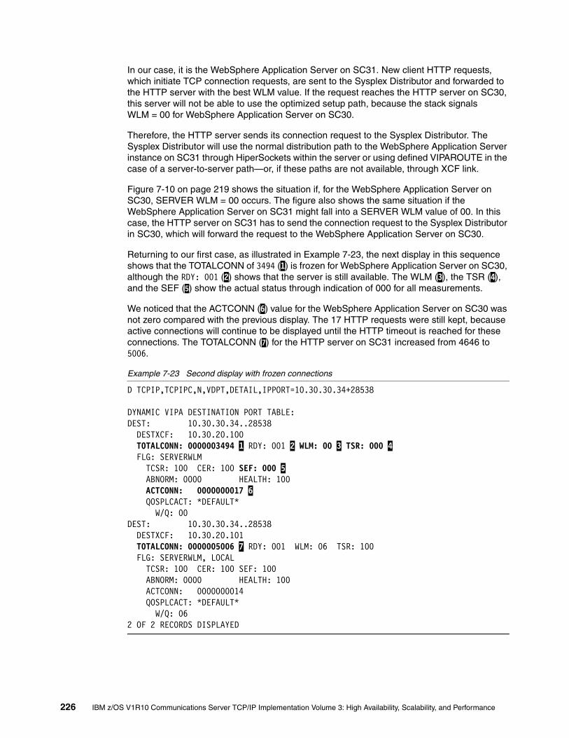
In our case, it is the WebSphere Application Server on SC31. New client HTTP requests, which initiate TCP connection requests, are sent to the Sysplex Distributor and forwarded to the HTTP server with the best WLM value. If the request reaches the HTTP server on SC30, this server will not be able to use the optimized setup path, because the stack signals WLM = 00 for WebSphere Application Server on SC30.
Therefore, the HTTP server sends its connection request to the Sysplex Distributor. The Sysplex Distributor will use the normal distribution path to the WebSphere Application Server instance on SC31 through HiperSockets within the server or using defined VIPAROUTE in the case of a server-to-server path—or, if these paths are not available, through XCF link.
Figure 7-10 on page 219 shows the situation if, for the WebSphere Application Server on SC30, SERVER WLM = 00 occurs. The figure also shows the same situation if the WebSphere Application Server on SC31 might fall into a SERVER WLM value of 00. In this case, the HTTP server on SC31 has to send the connection request to the Sysplex Distributor in SC30, which will forward the request to the WebSphere Application Server on SC30.
Returning to our first case, as illustrated in Example 7-23, the next display in this sequence shows that the TOTALCONN of 3494 (1) is frozen for WebSphere Application Server on SC30, although the RDY: 001 (2) shows that the server is still available. The WLM (3), the TSR (4), and the SEF (5) show the actual status through indication of 000 for all measurements.
We noticed that the ACTCONN (6) value for the WebSphere Application Server on SC30 was not zero compared with the previous display. The 17 HTTP requests were still kept, because active connections will continue to be displayed until the HTTP timeout is reached for these connections. The TOTALCONN (7) for the HTTP server on SC31 increased from 4646 to 5006.
Example 7-23 Second display with frozen connections
D TCPIP,TCPIPC,N,VDPT,DETAIL,IPPORT=10.30.30.34+28538
DYNAMIC VIPA DESTINATION PORT TABLE: DEST: 10.30.30.34..28538 DESTXCF: 10.30.20.100 TOTALCONN: 0000003494 1 RDY: 001 2 WLM: 00 3 TSR: 000 4 FLG: SERVERWLM TCSR: 100 CER: 100 SEF: 000 5 ABNORM: 0000 HEALTH: 100 ACTCONN: 0000000017 6 QOSPLCACT: *DEFAULT* W/Q: 00 DEST: 10.30.30.34..28538 DESTXCF: 10.30.20.101 TOTALCONN: 0000005006 7 RDY: 001 WLM: 06 TSR: 100 FLG: SERVERWLM, LOCAL TCSR: 100 CER: 100 SEF: 100 ABNORM: 0000 HEALTH: 100 ACTCONN: 0000000014 QOSPLCACT: *DEFAULT* W/Q: 06 2 OF 2 RECORDS DISPLAYED
226 IBM z/OS V1R10 Communications Server TCP/IP Implementation Volume 3: High Availability, Scalability, and Performance

OPTLOCAL 4 with Sysplex Distributor onlyIn previous sections, we discussed OPTLOCAL 0 and 1. The values 2 through 16 can also be used. They are applied to the amount of preference for the local server based on a comparison of WLM weights.
To give the local stack a higher preference even if it does not have the best WLM value, use an OPTLOCAL value of 2 to 16 as a multiplier to manipulate the WLM calculation. This allows you to prefer the local server even if the server WLM value for the local stack is much lower than others of the same servers in the server group.
For example, server WLM = 05 was defined on SC30. On the other LPARs, server WLM values were 12, 14, or 15. If OPTLOCAL 4 was defined, then the local WLM value is multiplied by the defined OPTLOCAL value. If OPTLOCAL 4 is defined on SC30, then the local WLM value is multiplied by the defined OPTLOCAL value. This means 20 (5 X4) will be compared with all servers’ WLM values of the same server group. Thus, the local server (SC30) will be favored because it has the highest value.
TCP/IP profile definitionsOnly OPTLOCAL 4 was defined on the VIPADISTRIBUTE statement, as shown in Example 7-24.
Example 7-24 TCP/IP profile for OPTLOCAL 4
VIPADynamic VIPADEFine MOVEable IMMEDiate 255.255.255.0 10.30.30.33 VIPADISTribute DISTMethod SERVERWLM 10.30.30.33 PORT 80 DESTIP 10.30.20.100 10.30.20.101 VIPADEFine MOVEable IMMEDiate 255.255.255.0 10.30.30.34 VIPADISTribute DISTMethod SERVERWLM optlocal 4 10.30.30.34 PORT 28538 28518 28510 28502 28503 DESTIP 10.30.20.100 10.30.20.101ENDVIPADYNAMIC
Verification Use the netstat vipadcfg command to show the correct OPTLOCAL 4 definition for the distributed DVIPA on SC30 and SC31 (as shown in Example 7-25):
� SC30 with DXCF IP address 10.30.20.100� SC31 with DXCF IP address 10.30.20.101
Example 7-25 TCP/IP profile for OPTLOCAL 4
D TCPIP,TCPIPC,N,VIPADCFG,DETAIL
DYNAMIC VIPA INFORMATION: VIPA DEFINE:
IPADDR/PREFIXLEN: 10.30.30.33/24 MOVEABLE: IMMEDIATE SRVMGR: NO IPADDR/PREFIXLEN: 10.30.30.34/24 MOVEABLE: IMMEDIATE SRVMGR: NO DEST: 10.30.30.33..80 DESTXCF: 10.30.20.100 SYSPT: NO TIMAFF: NO FLG: SERVERWLM OPTLOC: NO DEST: 10.30.30.33..80 DESTXCF: 10.30.20.101 SYSPT: NO TIMAFF: NO FLG: SERVERWLM
Chapter 7. Intra-sysplex workload balancing 227

OPTLOC: NO DEST: 10.30.30.34..28538 DESTXCF: 10.30.20.100 SYSPT: NO TIMAFF: NO FLG: SERVERWLM OPTLOCAL OPTLOC: 4 DEST: 10.30.30.34..28538 DESTXCF: 10.30.20.101
SYSPT: NO TIMAFF: NO FLG: SERVERWLM OPTLOCAL OPTLOC: 4
The netstat vipadyn command displays the date and time when the DVIPAs are activated, as shown in Example 7-26.
Example 7-26 Date and time of DVPA activation
D TCPIP,TCPIPC,N,VIPADYN
DYNAMIC VIPA: IPADDR/PREFIXLEN: 10.30.30.32/24 STATUS: ACTIVE ORIGIN: VIPADEFINE DISTSTAT: DIST/DEST ACTTIME: 08/23/2006 17:06:01 IPADDR/PREFIXLEN: 10.30.30.33/24 STATUS: ACTIVE ORIGIN: VIPADEFINE DISTSTAT: DIST/DEST ACTTIME: 08/23/2006 17:06:01 IPADDR/PREFIXLEN: 10.30.30.34/24 STATUS: ACTIVE ORIGIN: VIPADEFINE DISTSTAT: DIST/DEST ACTTIME: 08/23/2006 17:06:01 IPADDR/PREFIXLEN: 10.30.80.10/24 STATUS: ACTIVE ORIGIN: VIPARANGE BIND DISTSTAT: ACTTIME: 08/23/2006 17:10:52 JOBNAME: LBADV VIPA ROUTE: DESTXCF: 10.30.20.100 TARGETIP: 10.30.1.230 RTSTATUS: DEFINED DESTXCF: 10.30.20.101 TARGETIP: 10.30.1.242 RTSTATUS: ACTIVE DESTXCF: 10.30.20.102 TARGETIP: 10.30.1.221 RTSTATUS: ACTIVE 7 OF 7 RECORDS DISPLAYED
Example 7-27 shows the first display of the VIPA distribution port table after a restart of SC30 with OPTLOCAL option 4. Both WebSphere Application Servers received equal numbers of connections. The load distribution is equal.
Example 7-27 First display of VIPA distribution port table with OPTLOCA 4
D TCPIP,TCPIPC,N,VDPT,DETAIL,IPPORT=10.30.30.34+28538
DYNAMIC VIPA DESTINATION PORT TABLE: DEST: 10.30.30.34..28538 DESTXCF: 10.30.20.100 TOTALCONN: 0000000038 RDY: 001 WLM: 08 TSR: 100 FLG: SERVERWLM, LOCAL TCSR: 100 CER: 100 SEF: 100
228 IBM z/OS V1R10 Communications Server TCP/IP Implementation Volume 3: High Availability, Scalability, and Performance

ABNORM: 0000 HEALTH: 100 ACTCONN: 0000000005 QOSPLCACT: *DEFAULT* W/Q: 08 DEST: 10.30.30.34..28538 DESTXCF: 10.30.20.101 TOTALCONN: 0000000038 RDY: 001 WLM: 08 TSR: 100 FLG: SERVERWLM, LOCAL TCSR: 100 CER: 100 SEF: 100 ABNORM: 0000 HEALTH: 100 ACTCONN: 0000000007 QOSPLCACT: *DEFAULT* W/Q: 08
The VIPA connection routing table for the two WebSphere Application Servers displays the following distributions, as shown in Example 7-28:
� Six connections were distributed from the SOURCEVIPA 10.30.1.230, which used the HTTP server on SC30 to the WebSphere Application Server on SC30 with DXCF IP address 10.30.20.100 using cluster IP address 10.30.30.34 with a port address of 28538.
� Nine connections were distributed from the SOURCEVIPA 10.30.1.242, which used the HTTP server on SC31 to the WebSphere Application Server on SC31 with DXCF IP address 10.30.20.101, using cluster address 10.30.30.34 with a port address of 28538.
Example 7-28 Netstat VCRT of first connections to WebSphere Application Server
D TCPIP,TCPIPC,N,VCRT,DETAIL,IPPORT=10.30.30.34+28538
DYNAMIC VIPA CONNECTION ROUTING TABLE: .......... first two connections from HTTP server on SC30 to WAS on SC30 .........DEST: 10.30.30.34..28538 SOURCE: 10.30.1.230..1132 DESTXCF: 10.30.20.100 POLICYRULE: *NONE* POLICYACTION: *NONE* DEST: 10.30.30.34..28538 SOURCE: 10.30.1.230..1133 DESTXCF: 10.30.20.100 POLICYRULE: *NONE* POLICYACTION: *NONE* .......... first two connections from HTTP server on SC31 to WAS on SC31 .........DEST: 10.30.30.34..28538 SOURCE: 10.30.1.242..1172 DESTXCF: 10.30.20.101 POLICYRULE: *NONE* POLICYACTION: *NONE* DEST: 10.30.30.34..28538 SOURCE: 10.30.1.242..1173 DESTXCF: 10.30.20.101 POLICYRULE: *NONE* POLICYACTION: *NONE*
Stopping WebSphere Application Server on SC30During the test with the workload simulator, we could not increase the load of one system to discover a recalculation of a fictive WLM value. Therefore, we decided to stop the WebSphere
Chapter 7. Intra-sysplex workload balancing 229

Application Server application on SC30 and check whether the distribution worked with the OPTLOCAL 4 option.
When the WebSphere Application Server on SC30 was purged, the RDY = 001, the WLM = 0, and the TSR and SEF were 000, as expected. TOTALCONN was frozen with 1328 connections for SC30. TOTALCONN: 1448 on SC31 will increase in the next display.
Example 7-29 WebSphere Application Server on SC30 was stopped, service is still running
D TCPIP,TCPIPC,N,VDPT,DETAIL,IPPORT=10.30.30.34+28538
DYNAMIC VIPA DESTINATION PORT TABLE: DEST: 10.30.30.34..28538 DESTXCF: 10.30.20.100 TOTALCONN: 0000001328 RDY: 001 WLM: 00 TSR: 000 FLG: SERVERWLM TCSR: 100 CER: 100 SEF: 000 ABNORM: 0000 HEALTH: 100 ACTCONN: 0000000024 QOSPLCACT: *DEFAULT* W/Q: 00 DEST: 10.30.30.34..28538 DESTXCF: 10.30.20.101 TOTALCONN: 0000001448 RDY: 001 WLM: 06 TSR: 100 FLG: SERVERWLM, LOCAL TCSR: 100 CER: 100 SEF: 100 ABNORM: 0000 HEALTH: 100 ACTCONN: 0000000012 QOSPLCACT: *DEFAULT* W/Q: 06 2 OF 2 RECORDS DISPLAYED
Although the WebSphere Application Server on SC30 was now down, both HTTP servers distributed to SC31 WebSphere Application Server, as shown in Example 7-30.
Example 7-30 WebSphere Application Server on SC30 is down, HTTP servers distribute to WebSphere Application Server on SC31
D TCPIP,TCPIPC,N,VCRT,DETAIL,IPPORT=10.30.30.33+80
DYNAMIC VIPA CONNECTION ROUTING TABLE.............. first two connections from workload simulator to HTTP server on SC30 ......DEST: 10.30.30.33..80 SOURCE: 10.30.2.50..2084 DESTXCF: 10.30.20.100 POLICYRULE: *NONE* POLICYACTION: *NONE* DEST: 10.30.30.33..80 SOURCE: 10.30.2.50..2232 DESTXCF: 10.30.20.100 ............. first two connections from workload simulator to HTTP server on SC31 ......DEST: 10.30.30.33..80 SOURCE: 10.30.2.50..2230 DESTXCF: 10.30.20.101 POLICYRULE: *NONE*
230 IBM z/OS V1R10 Communications Server TCP/IP Implementation Volume 3: High Availability, Scalability, and Performance
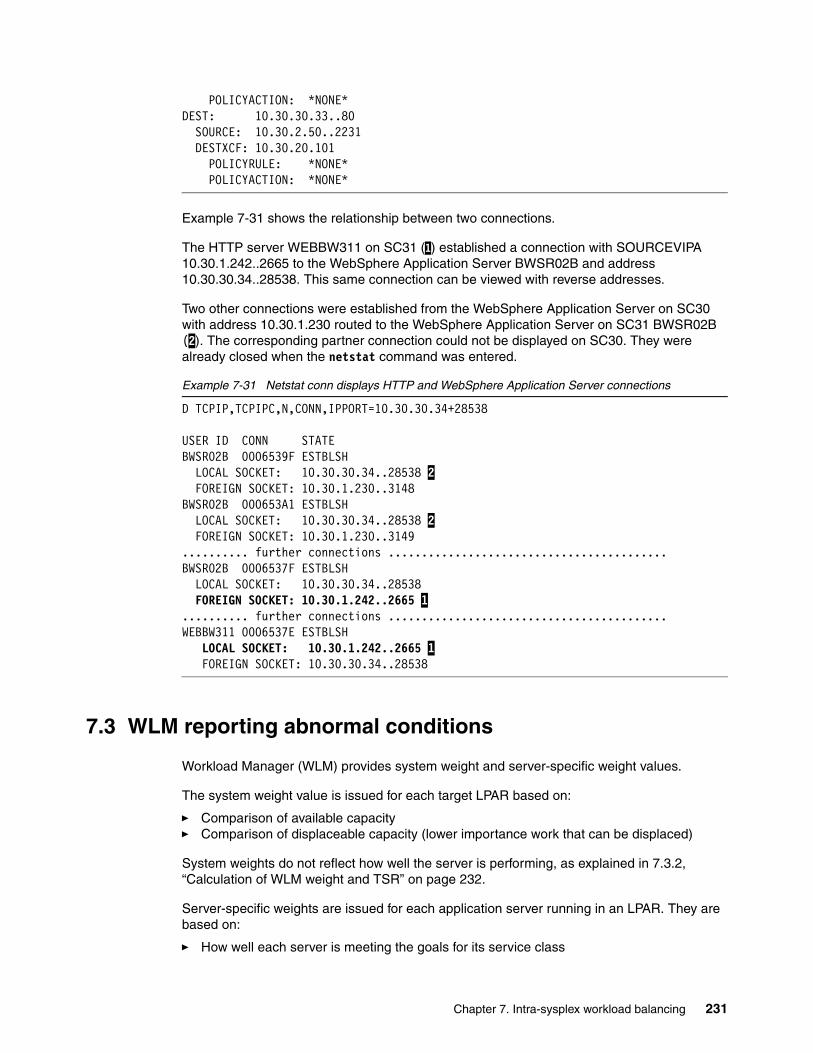
POLICYACTION: *NONE* DEST: 10.30.30.33..80 SOURCE: 10.30.2.50..2231 DESTXCF: 10.30.20.101 POLICYRULE: *NONE* POLICYACTION: *NONE*
Example 7-31 shows the relationship between two connections.
The HTTP server WEBBW311 on SC31 (1) established a connection with SOURCEVIPA 10.30.1.242..2665 to the WebSphere Application Server BWSR02B and address 10.30.30.34..28538. This same connection can be viewed with reverse addresses.
Two other connections were established from the WebSphere Application Server on SC30 with address 10.30.1.230 routed to the WebSphere Application Server on SC31 BWSR02B (2). The corresponding partner connection could not be displayed on SC30. They were already closed when the netstat command was entered.
Example 7-31 Netstat conn displays HTTP and WebSphere Application Server connections
D TCPIP,TCPIPC,N,CONN,IPPORT=10.30.30.34+28538
USER ID CONN STATE BWSR02B 0006539F ESTBLSH LOCAL SOCKET: 10.30.30.34..28538 2 FOREIGN SOCKET: 10.30.1.230..3148 BWSR02B 000653A1 ESTBLSH LOCAL SOCKET: 10.30.30.34..28538 2 FOREIGN SOCKET: 10.30.1.230..3149 .......... further connections ..........................................BWSR02B 0006537F ESTBLSH LOCAL SOCKET: 10.30.30.34..28538 FOREIGN SOCKET: 10.30.1.242..2665 1 .......... further connections ..........................................WEBBW311 0006537E ESTBLSH LOCAL SOCKET: 10.30.1.242..2665 1 FOREIGN SOCKET: 10.30.30.34..28538
7.3 WLM reporting abnormal conditions
Workload Manager (WLM) provides system weight and server-specific weight values.
The system weight value is issued for each target LPAR based on:
� Comparison of available capacity� Comparison of displaceable capacity (lower importance work that can be displaced)
System weights do not reflect how well the server is performing, as explained in 7.3.2, “Calculation of WLM weight and TSR” on page 232.
Server-specific weights are issued for each application server running in an LPAR. They are based on:
� How well each server is meeting the goals for its service class
Chapter 7. Intra-sysplex workload balancing 231

� Comparison of displaceable capacity on each system based on the importance of the server’s work.
The following sections explain the situations and conditions that impact the complexity of workload decisions, and how they are resolved in a design for the Sysplex Distributor environment.
7.3.1 Situation of current workload distribution decisions
WLM is not aware of all problems experienced by load balancing targets; this might occur, for example, when a server application needs a resource such as a database, but the resource is unavailable. Another example is a server application that acts as a transaction router for other back-end applications on other systems, but the path to the back-end application is unavailable.
In each of these scenarios, the server appears to be completing the transactions quickly (using little CPU capacity), although it is actually failing. This situation is known as a “storm drain” problem. The result is:
� The server is favored by WLM, because it is using very little CPU capacity.
� As workloads increase, the server is favored more and more over other servers.
� All this work goes “down the drain”.
Although the Sysplex Distributor is able to reduce the WLM weight values by using the Target Server Responsiveness fraction (TSR), the storm drain problem cannot be resolved.
The TSR fraction is built based on three factors:
� Is the connectivity between the distributing stack and the target stack stable? Are new connections being received by the target stack?
– This factor is the Target Connectivity Success Rate (TCSR).
� Is the network connectivity between server and client in a good state? Can new connections be established?
– This factor is the Connection Establishment Rate (CER).
� Is the target server application accepting new work? What target server responsiveness does the application show? Is the backlog queue overloaded?
– This factor is the Server Efficiency Fraction (SEF).
These factors are depicted in Figure 7-11 on page 233.
7.3.2 Calculation of WLM weight and TSR
The calculation of WLM weights and the TSR determines which target application server gets the work requests, such as the TCP connection request forwarded by the Sysplex Distributor or the external load balancer, as explained here:
� WLM weights
When determining a system weight, WLM assigns a relative weight to each system in the sysplex, with the highest weight going to the system with the most available CPU capacity. The weights range between 0 & 64.
If all systems in the sysplex are running at or near 100% utilization, WLM will assign the highest weights to the systems with the largest amounts of lower importance work. In this
232 IBM z/OS V1R10 Communications Server TCP/IP Implementation Volume 3: High Availability, Scalability, and Performance

way, new connection requests will be distributed to the systems with the highest displaceable capacity.
However, note the following points:
– This method does not reflect how well the server application is actually meeting the goals of its service class.
– If all systems are using close to 100% of capacity, then the WLM weight is based on a comparison of displaceable capacity, which is the amount of lower importance work on each system. However, if the service class of the server is of low importance, then it might not be able to displace this work.
When determining a server-specific weight, WLM assigns a relative weight to each server based on how well each server is meeting the goals of its service class. The weights range between 0 - 64. If all systems in the sysplex are running at or near 100% utilization, WLM will assign the highest weights to the servers running on systems with the largest amounts of work that can be displaced by that server (based on the importance of its service class)
� Calculation of TSR
– SEF - This value is based on whether the server is processing new connections
• New connections are being established - Connection Establishment Rate (CER).• The server is accepting the new connections.
– TCSR - The distributor determines this value from the number SYNs it has sent to the target and the statistics returned from the target.
– TSR - This is based on the SEF value (which includes CER) and TCSR values.
Figure 7-11 shows that distributed DVIPA1 for port 8000 is defined with DISTMETHOD SERVERWLM to DESTIP target 1 and target 2.
Figure 7-11 Workload distribution weight fractions
The Sysplex Distributor receives a calculated weight value of 40 for Target 1, and 32 for Target 2. Because the TSR for both targets is reported 100%, both weight values are not minimized. At a lower percentage the calculation would be: Weight * TSR% = Weight fraction. The next step is normalizing the weight. This is done by dividing the Weight fraction with the integer 4. This is done only to continue working with smaller values.
� For Target 1, the calculation is: normalized weight is 10 = (40 / 4).
� For Target 2, the calculation is: normalized weight is 8 = (32 / 4).
ClientCER2
Target 2 System
Target 1 System
Server 1SEF3
Stack DVIPA1, 8000 SEF
100 %
TCSR
1
DistributorDVIPA1 PORT 8000 Wt.
Target 1 40Target 2 32
TSR
100%
norm. Wt.
108
100%
SEF/Serv Stats
Server Sp Wts.
WLM
Server Sp Wts. 32
Server Sp Wts. 40
Chapter 7. Intra-sysplex workload balancing 233

7.3.3 WLM interface for abnormal transactions and health status
WLM provides an interface that allows a server to pass additional information about its overall health. This overall health information consists of two values:
� Abnormal transaction completion rate
Applications such as CICS transaction server for z/OS, that act as subsystem work managers, can report an abnormal transaction completion rate to WLM. The value is between 0 and 1000, with 0 meaning no abnormal completions.
� General health of the application
Applications can report their general health to WLM. The value is between 0 and 100, with 100 meaning that a server has no general health problems (100% healthy).
WLM will reduce the reported weight based on Abnormal Completion Rate and the General Health.
Figure 7-12 illustrates how the abnormal transaction completion rate of 1000 impacts the server-specific weight value, and also how the Sysplex Distributor uses the normalized value of zero (0) instead the previous displayed value of 10 for Target 1.
Figure 7-12 Workload distribution with additional weight fractions
Server scenariosThe TCP/IP stack retrieves the information about abnormal transaction termination and health of the application using the IWM4SRSC interface.
� Abnormal termination
This information solves the problem where the registered server is not the transaction consumer. It does not, however, resolve the problem where another connector is between the TCP/IP stack and the consumer.
� HEALTH
Address spaces which are not instrumented can use the IWM4HLTH interface to WLM to set a health status, which is also returned by IWM4SRSC.
ClientCER2
Target 2 System
Target 1 System
Server 1SEF3
Stack DVIPA1, 8000 SEF
100 %
TCSR
1
DistributorDVIPA1 PORT 8000 Wt.
Target 1 0Target 2 32
TSR
100%
norm. Wt.
08
100%
SEF/Serv Stats
Server Sp Wts.
WLM
Server Sp Wts. 32
Server Sp Wts. 0abnorm 1000health 100
234 IBM z/OS V1R10 Communications Server TCP/IP Implementation Volume 3: High Availability, Scalability, and Performance

Figure 7-13 depicts the differences between the information TCP/IP receives through these two interfaces.
Figure 7-13 WLM target application awareness
VerificationThe netstat commands in Example 7-32 show samples for the health indicator, active connections, and abnormal termination.
Example 7-32 netstat command for VIPA distribution port table, short format
D TCPIP,TCPIPC,N,VDPT
DYNAMIC VIPA DESTINATION PORT TABLE: DEST: 10.30.30.32..23 DESTXCF: 10.30.20.102 TOTALCONN: 0000000000 RDY: 001 WLM: 15 TSR: 100 FLG: BASEWLM DEST: 10.30.30.33..80 DESTXCF: 10.30.20.100 TOTALCONN: 0000000000 RDY: 000 WLM: 00 TSR: 100 FLG: SERVERWLM
If you use the netstat command with format detail, you will get the desired information about WLM, TSR, TCSR, CER, SEF, ABNORM, and HEALTH values. you will also see the active connections for the distributed server; see Example 7-33.
Example 7-33 netstat command for VIPA distribution port table, long format
D TCPIP,TCPIPC,N,VDPT,DETAIL
DYNAMIC VIPA DESTINATION PORT TABLE:DEST: 10.30.30.32..23
WLMTransaction Service Class
Server-specific CapacityAbnormal Transactions
WLM instrumented and managed
CICS DB2
z/OS
WLMSTC Service Class
Server-specific CapacityHealth Status
Connector address space
WLM instrumented and managed
EISz/OS
TCPIP
TCPIP
SD TCPIP
1
1
2
2
1 IWM4SRSC
IWM4HLTH
Chapter 7. Intra-sysplex workload balancing 235

DESTXCF: 10.30.20.100 TOTALCONN: 0000000000 RDY: 001 WLM: 05 TSR: 100 FLG: BASEWLM TCSR: 100 CER: 100 SEF: 100 ABNORM: 0000 HEALTH: 100 ACTCONN: 0000000000 QOSPLCACT: *DEFAULT* W/Q: 05 DEST: 10.30.30.32..23 DESTXCF: 10.30.20.101 TOTALCONN: 0000000000 RDY: 001 WLM: 04 TSR: 100 FLG: BASEWLM TCSR: 100 CER: 100 SEF: 100 ABNORM: 0000 HEALTH: 100 ACTCONN: 0000000000 QOSPLCACT: *DEFAULT* W/Q: 04
When issuing the netstat all command, you will get information indicating how many connections were dropped, if the backlog is overloaded (current backlog and max. backlog).
This is defined through the SMAXCONN statement in the TCP/IP profile (the default is 10); see Example 7-34.
Example 7-34 The netstat all command
===> netstat all
Client Name: BWSR02B Client Id: 000013AB Local Socket: ::..28530 Foreign Socket: ::..0 BytesIn: 00000000000000000000 BytesOut: 00000000000000000000 SegmentsIn: 00000000000000000000 SegmentsOut: 00000000000000000000 Last Touched: 16:03:39 State: Listen RcvNxt: 0000000000 SndNxt: 0000000000
ClientRcvNxt: 0000000000 ClientSndNxt: 0000000000InitRcvSeqNum: 0000000000 InitSndSeqNum: 0000000000CongestionWindow: 0000000000 SlowStartThreshold: 0000000000IncomingWindowNum: 0000000000 OutgoingWindowNum: 0000000000SndWl1: 0000000000 SndWl2: 0000000000SndWnd: 0000000000 MaxSndWnd: 0000000000SndUna: 0000000000 rtt_seq: 0000000000MaximumSegmentSize: 0000000536 DSField: 00 Round-trip information:
Smooth trip time: 0.000 SmoothTripVariance: 1500.000 ReXmt: 0000000000 ReXmtCount: 0000000000DupACKs: 0000000000 SockOpt: 8000 TcpTimer: 00 TcpSig: 01 TcpSel: 20 TcpDet: C0 TcpPol: 08 QOSPolicyRuleName: ReceiveBufferSize: 0000016384 SendBufferSize: 0000016384ConnectionsIn: 0000000000 ConnectionsDropped: 0000000000CurrentBacklog: 0000000000 MaximumBacklog: 0000000010
236 IBM z/OS V1R10 Communications Server TCP/IP Implementation Volume 3: High Availability, Scalability, and Performance

CurrentConnections: 0000000000 SEF: 100 Quiesced: No
You can check the distribution method and the OPTLOCAL value using netstat VIPDCFG, as shown in Example 7-35.
Example 7-35 netstat vipadcfg short format
D TCPIP,TCPIPC,N,VIPADCFG
DYNAMIC VIPA INFORMATION: VIPA DEFINE:
IPADDR/PREFIXLEN: 10.30.30.33/24 MOVEABLE: IMMEDIATE SRVMGR: NO
IPADDR/PREFIXLEN: 10.30.30.34/24 MOVEABLE: IMMEDIATE SRVMGR: NO
VIPA DISTRIBUTE: DEST: 10.30.30.33..80
DESTXCF: 10.30.20.100 SYSPT: NO TIMAFF: NO FLG: SERVERWLM DEST: 10.30.30.33..80 DESTXCF: 10.30.20.101 SYSPT: NO TIMAFF: NO FLG: SERVERWLM
The netstat vipadcfg command shows the defined OPTLOCAL value; see Example 7-36.
Example 7-36 netstat vipdcfg long format
D TCPIP,TCPIPC,N,VIPADCFG,DETAIL
DYNAMIC VIPA INFORMATION: VIPA DEFINE:
IPADDR/PREFIXLEN: 10.30.30.33/24 MOVEABLE: IMMEDIATE SRVMGR: NO IPADDR/PREFIXLEN: 10.30.30.34/24 MOVEABLE: IMMEDIATE SRVMGR: NO
DEST: 10.30.30.34..28538 DESTXCF: 10.30.20.100 SYSPT: NO TIMAFF: NO FLG: SERVERWLM OPTLOCAL OPTLOC: 4 DEST: 10.30.30.34..28538 DESTXCF: 10.30.20.101 SYSPT: NO TIMAFF: NO FLG: SERVERWLM OPTLOCAL OPTLOC: 4
You can also obtain ABNORM and HEALTH information through the LBAdvisor to check if the WLM weight is being influenced by these factors; see Example 7-37.
Example 7-37 F LBADV, DISP
F LBADV,DISP,LB,I=0EZD1243I LOAD BALANCER DETAILSLB INDEX : 00 UUID : 637FFF175C...GROUP NAME : CICS_SERVERGROUP FLAGS : SERVERWLM
Chapter 7. Intra-sysplex workload balancing 237

IPADDR..PORT: 201.2.10.11..8000SYSTEM NAME: MVS209 PROTOCOL : TCP AVAIL : YESWLM WEIGHT : 00000 CS WEIGHT : 100 NET WEIGHT: 00001ABNORM : 01000 HEALTH : 100FLAGS :
238 IBM z/OS V1R10 Communications Server TCP/IP Implementation Volume 3: High Availability, Scalability, and Performance

Chapter 8. Performance and tuning
A system delivering poor response times to a user can be perceived as unavailable from the user’s viewpoint. TCP/IP performance is influenced by a number of parameters that can be tailored for the specific operating environment. This includes not only TCP/IP stack performance that benefits all applications using the stack, but also applications that are part of the z/OS Communications Server shipment, such as TN3270 and FTP.
Because every TCP/IP environment is different, optimum performance can be achieved only when the system is tuned to match its specific environment. In this chapter, we highlight the most important tuning parameters, and also suggest parameter values that have maximized performance in many client installations.
This chapter discusses the following topics.
8
Section Topic
8.1, “General performance considerations” on page 240
Factors influencing performance
8.2, “TCP/IP configuration files” on page 242 Significant configuration files for z/OS TCP/IP
8.3, “z/OS UNIX System Services tuning” on page 249
Useful tuning information
8.4, “Storage requirements” on page 249 Storage usage summaries for typical applications
8.5, “Application performance and capacity” on page 254
Telnet (TN3270) capacity planning, FTP tuning, and FTP capacity planning information
8.6, “z/OS Communications Server TCP/IP performance enhancements highlights” on page 256
z/OS Communications Server TCP/IP performance enhancements (all automatically enabled)
8.7, “TCP/IP performance quick checklist” on page 258
Performance items to consider
8.8, “Health Checker” on page 259 Health Checker checks information
© Copyright IBM Corp. 2009. All rights reserved. 239
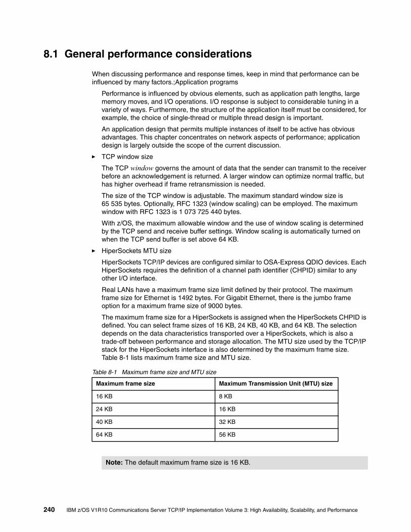
8.1 General performance considerations
When discussing performance and response times, keep in mind that performance can be influenced by many factors.;Application programs
Performance is influenced by obvious elements, such as application path lengths, large memory moves, and I/O operations. I/O response is subject to considerable tuning in a variety of ways. Furthermore, the structure of the application itself must be considered, for example, the choice of single-thread or multiple thread design is important.
An application design that permits multiple instances of itself to be active has obvious advantages. This chapter concentrates on network aspects of performance; application design is largely outside the scope of the current discussion.
� TCP window size
The TCP window governs the amount of data that the sender can transmit to the receiver before an acknowledgement is returned. A larger window can optimize normal traffic, but has higher overhead if frame retransmission is needed.
The size of the TCP window is adjustable. The maximum standard window size is 65 535 bytes. Optionally, RFC 1323 (window scaling) can be employed. The maximum window with RFC 1323 is 1 073 725 440 bytes.
With z/OS, the maximum allowable window and the use of window scaling is determined by the TCP send and receive buffer settings. Window scaling is automatically turned on when the TCP send buffer is set above 64 KB.
� HiperSockets MTU size
HiperSockets TCP/IP devices are configured similar to OSA-Express QDIO devices. Each HiperSockets requires the definition of a channel path identifier (CHPID) similar to any other I/O interface.
Real LANs have a maximum frame size limit defined by their protocol. The maximum frame size for Ethernet is 1492 bytes. For Gigabit Ethernet, there is the jumbo frame option for a maximum frame size of 9000 bytes.
The maximum frame size for a HiperSockets is assigned when the HiperSockets CHPID is defined. You can select frame sizes of 16 KB, 24 KB, 40 KB, and 64 KB. The selection depends on the data characteristics transported over a HiperSockets, which is also a trade-off between performance and storage allocation. The MTU size used by the TCP/IP stack for the HiperSockets interface is also determined by the maximum frame size. Table 8-1 lists maximum frame size and MTU size.
Table 8-1 Maximum frame size and MTU size
Maximum frame size Maximum Transmission Unit (MTU) size
16 KB 8 KB
24 KB 16 KB
40 KB 32 KB
64 KB 56 KB
Note: The default maximum frame size is 16 KB.
240 IBM z/OS V1R10 Communications Server TCP/IP Implementation Volume 3: High Availability, Scalability, and Performance

� Frame size/MTU size
Data is transported across the Ethernet in frames. Frame size is limited by the type of Ethernet architecture in use, by the equipment in use, and by the settings of the system.
The Ethernet type determines the maximum payload size, and thus the frame size. For Ethernet-DIX the maximum payload is 1500 bytes. For Ethernet-IEEE 802.3 LAN, the maximum is 1492 bytes (which results in 1500 bytes after including additional headers). In practice, most Ethernet usage involves the DIX format.
With z/OS, the MTU is set in the TCP/IP profile. Some vendor equipment allows frames to exceed the maximum allowed by the standards cited here. A frame that is larger than the standard is a jumbo frame. When operating in QDIO mode, OSA-Express and OSA-Express2 support jumbo frames. The largest jumbo supported holds an MTU of 8992 bytes (9000 bytes for IPv6).
Use the PMTU option on the ping command to determine where fragmentation is necessary in the network. The PMTU YES option differs from the PMTU IGNORE option in the way the ping completes its echo function. Refer to z/OS Communications Server: IP System Administrator’s Commands, SC31-8781, for a detailed discussion about the PMTU option.
� OSA-Express and OSA-Express2 features
The OSA-Express and OSA-Express2 features contain hardware and firmware that enable the flow of traffic between the Ethernet link and host memory. Traffic flowing through the OSA is stored in OSA-memory before being forwarded to the host or LAN.
This design optimizes host memory access. The OSA microprocessor manages the flow of traffic through the OSA. A utilization of over 90% could indicate that the OSA is nearing capacity. In some cases OSA becomes more efficient as traffic increases, even at high utilizations. This is because OSA can transfer more packets per block when moving data between host memory and OSA memory.
� Dynamic LAN idle
Dynamic LAN idle is designed to reduce latency and improve network performance by dynamically adjusting the inbound blocking algorithm. It is exclusive to z9 EC and z9 BC and applicable to the OSA-Express2 features (CHPID type OSD).
When enabled, the TCP/IP stack will adjust the inbound blocking algorithm to best match the application requirements. The TCP/IP stack will dynamically determine the best setting for the current running application based on system configuration, inbound workload volume, CPU utilization, and traffic patterns. Refer to “OSA-Express2 LAN idle timer function” on page 246 for configuration examples.
Note: To avoid incompatibilities between DIX and 802.3 ports, keep the MTU size at or below 1492 bytes for standard frames.
Note: At high loads, response time might be more of a concern than utilization, especially when running interactive traffic.
Chapter 8. Performance and tuning 241

8.2 TCP/IP configuration files
The most important configuration files for z/OS TCP/IP are the following:
� PROFILE.TCPIP
The PROFILE.TCPIP file contains TCP buffer sizes, LAN device definitions, server ports, home IP addresses, gateway and route statements, VTAM LUs for Telnet use, and so forth. Buffers are dynamically allocated by the Communications Storage Manager (CSM) and are not specified in PROFILE.TCPIP.
� FTP.DATA
The FTP.DATA file is used by the FTP server and FTP client to establish the initial configuration options. FTP.DATA contains items such as default DCB parameters for new data sets, the checkpoint interval, and so forth.
� TCPIP.DATA
TCPIP.DATA contains host name, domain origin, and name server definitions.
8.2.1 MTU considerations
The maximum transmission unit (MTU) specifies the largest packet that TCP/IP will transmit over a given interface. Be certain to specify a packet size explicitly instead of using DEFAULTSIZE. The DEFAULTSIZE produces a value of 576 bytes, which is unlikely to be optimal.
Every network consists of many components that must be carefully coordinated with each other. This also applies to finding the parameter setting of the largest possible MTU size in your installation. Table 8-2 provides an overview of the largest MTU sizes supported by different interfaces.
Table 8-2 Maximum MTU sizes of interfaces by Link type
The MTU size used for a given outbound frame depends on several factors:
� interface_MTU
This is either a hardcoded size based on the physical device, or a value obtained from the device during activation. For an active link or interface, TCP/IP reports the interface_MTU in the ActMtu field of the NETSTAT DEVLINKS -d command.
Note: A recommendation is to keep the statement TRACE RESOLVER commented out to avoid complete tracing of all name server queries. This trace should be used for debugging purposes only.
Link type Connectivity Maximum MTU size
Ethernet (DIX) Ethernet 1500
802.3 Ethernet 802.3 1492
CTC z/OS using CTC 65527
IPAQENET(OSA QDIO)
OSA-Express Gigabit Ethernet1000BASE-T
14928992 (Jumbo)
IPAQIDIO HiperSockets 57344
242 IBM z/OS V1R10 Communications Server TCP/IP Implementation Volume 3: High Availability, Scalability, and Performance

� configured_route_MTU
This is the MTU size configured for a route.
– For static routes, specify configured_route_MTU on either a ROUTE statement in a BEGINROUTES block or on a GATEWAY statement in the TCP/IP profile.
– For dynamic routes, the configured_route_MTU value comes from the value of the MTU keyword specified on the RIP_INTERFACE, OSPF_INTERFACE, or INTERFACE statement for that interface in the OMPROUTE configuration file. If you do not specify an MTU for an interface, OMPROUTE uses 576.
� actual_route_MTU
This is the minimum of the interface_MTU and the configured_route_MTU. When path MTU discovery is not in effect, TCP/IP uses the actual_route_MTU for sending outbound packets.
� path_MTU
This is the value determined by the path MTU discovery function. When path MTU discovery is in effect, TCP/IP uses path_MTU for sending outbound packets. You can enable path MTU discovery for IPv4 using IPCONFIG PATHMTUDISCOVERY.
Path MTU discovery starts by setting path_MTU to the actual_route_MTU of the route. If packets require fragmentation to get to the final destination, path MTU discovery finds the path_MTU by repeatedly decreasing the value until it can send packets to the final destination without fragmentation. Figure 8-1 illustrates this function.
Figure 8-1 Large MTU sizes have a very positive impact on file transfer type of workloads
Use the PMTU option on the ping command to determine where fragmentation is necessary in the network. The PMTU YES option differs from the PMTU IGNORE option in the way the ping completes its echo function. Refer to z/OS Communications Server: IP System Administrator’s Commands, SC31-8781, for a detailed discussion about the PMTU option.
INTERFACE MTU:hardcoded or learned from DEVICE
[GATEWAY]ROUTEBSDROUTINGPARMSOMPROUTE x_INTERFACE
CONFIGURED ROUTE MTU
ACTUAL ROUTE MTU:MIN(INTERFACE MTU, CONFIGURED ROUTE MTU)
ACTUAL PATH MTU SIZEMax value is the ACTUAL ROUTE MTU size
TCP SegmentTCP HdrIP HdrLink Hdr LinkTrailer
Segment Size
MTU Size = IP Packet Size
Frame Size
z/OS TCP/IP
ActMtu: 17914
Pkt Sz: 2000
Pkt Sz: 576
Use of Path MTU is by default disabled. You enable it via an IPConfig option:
PATHMTUDISCOVERY
Chapter 8. Performance and tuning 243

Note the following recommendations and guidelines:
� Enable path MTU discovery in configurations where traffic originating in the z/OS TCP/IP stack will traverse multiple hops with different MTU sizes.
� When using OSA-Express Gigabit Ethernet (which supports an interface MTU of 8992), be aware that not all routers and switches support a value this large. Either ensure that all routers and switches in your configuration support 8992, or specify a lower configured_route_MTU.
� When using OMPROUTE, specify the MTU keyword for each IPv4 interface and configure all nodes on a LAN to use the same MTU value. Otherwise, you might encounter problems, such as OSPF adjacency errors.
The ping command detection of network MTUThe ping command in z/OS Communications Server can be used as a diagnosis tool to determine MTU and fragmentation problems in the network. Path MTU parameters are added to the TSO and z/OS UNIX versions of the command to prevent the outbound echo request packets from being fragmented, and to specify the type of path MTU discovery support for the command.
Example 8-1 shows the output of the TSO command:
“ping 10.1.1.240 (tcp tcpipa count 4 pmtu ignore length 4096”
In this command output:
count 4: Sets the number of echo requests that are sent to the host.
pmtu ignore: Specifies that the outbound echo request packets are not fragmented at the local host or in the network, and that any MTU values determined by path MTU discovery for the destination are ignored.
length 4096: Sets the number of data bytes for the echo request.
Example 8-1 Output of TSO command ping PMTU
CS V1R10: Pinging host 10.1.1.240 Ping #1 needs fragmentation at: 10.1.3.11 (10.1.3.11) Next-hop MTU size is 1492 Ping #2 needs fragmentation at: 10.1.3.11 (10.1.3.11) Next-hop MTU size is 1492 Ping #3 needs fragmentation at: 10.1.3.11 (10.1.3.11) Next-hop MTU size is 1492 Ping #4 needs fragmentation at: 10.1.3.11 (10.1.3.11) Next-hop MTU size is 1492 ***
For more information about the ping command, refer to z/OS Communications Server: IP System Administrator’s Commands, SC31-8781.
Path MTU discovery for Enterprise ExtenderPath MTU discovery for Enterprise Extender (EE) enables VTAM to determine dynamically any MTU size changes that are associated with IPv4 and IPv6 EE connections in the IP network. VTAM can segment the HPR data to avoid IP packet fragmentation.
244 IBM z/OS V1R10 Communications Server TCP/IP Implementation Volume 3: High Availability, Scalability, and Performance

A VTAM start option, PMTUD, controls whether path MTU discovery is enabled for Enterprise Extender:
� When PMTUD=NO, VTAM disable path MTU discovery for IPv4 and IPv6 EE connections, VTAM will only learn of local MTU changes associated with first hop of the IP routes.
� When PMTUD=TCPVALUE, VTAM accepts the TCP/IP stack (associated with EE) setting. For IPv6 EE connections, path MTU discovery is enabled by default. For IPv4 EE connections, path MTU discovery is enabled when the PATHMTUDISCOVERY operand is coded on the IPCONFIG profile statement.
When VTAM detects the EE connection MTU size has changed during the transmission of an EE packet, the MTU size is altered. You can check the IST2029I message for the current MTU size using DISPLAY NET,EE,ID=name,LIST=DETAIL, as shown in Example 8-2.
Example 8-2 Output of command D NET,EE,ID=name,DETAIL
D NET,EE,ID=EEPUCS04,DETAIL IST097I DISPLAY ACCEPTED IST350I DISPLAY TYPE = EE 392 IST2001I ENTERPRISE EXTENDER CONNECTION INFORMATION IST075I NAME = EEPUCS04, TYPE = PU_T2.1 ...IST2030I PORT PRIORITY = SIGNAL IST2029I MTU SIZE = 1433 1 ...IST2031I PORT PRIORITY = NETWORK IST2029I MTU SIZE = 1433 ...IST2032I PORT PRIORITY = HIGH IST2029I MTU SIZE = 972 2 ...IST2033I PORT PRIORITY = MEDIUM IST2029I MTU SIZE = 972 2 ...IST2034I PORT PRIORITY = LOW IST2029I MTU SIZE = 1433 IST314I END
In this example, the numbers correspond to the following information:
1. This MTU size has already been reduced to account for various header lengths such as the IP, UDP, and LLC headers necessary for EE traffic.
2. EE only learns of MTU changes when HPR data is transmitted across each unique port. Because not all of the EE ports might be transmitting data simultaneously, you might see different MTU sizes for some of the EE ports.
Take into account the following implementation considerations:
� The learned path MTU is considered to be stale information every 20 minutes. By that time, the path MTU is reset to the first hop MTU size. The system will experience the same overhead of learning the path MTU at 20 minutes intervals.
� A firewall must permit ICMP messages when “Path MTU Discovery” is enabled. Otherwise, HPR transmission stall occurs if the path MTU is smaller than that of the “first hop” MTU size.
Chapter 8. Performance and tuning 245

In Figure 8-2, HPR transmits a large packet base on the path MTU size, and the TCP/IP stack turns on the “do not fragment” bit in the IPv4 header 1. When the packet arrives at the router with the smaller “next hop” MTU 2, an ICMP is returned, and the packet is discarded 3. If the firewall does not allow ICMP package, it drops the ICMP 4. The TCP/IP stack and VTAM will not learn of the path MTU. It retransmits these large missing packets when the partner reports a packet gap. This process repeats indefinitely and causes the “transmission stall” with message IST2245I.
Figure 8-2 ICMP message blocked by firewall
For more information about the path MTU discovery for EE, refer to z/OS V1R10 Communications Server: SNA network Implementation Guide, SC31-8777.
8.2.2 OSA-Express2 LAN idle timer function
OSA-Express supports an inbound “blocking” (or packing) function over the QDIO interface. This function affects how long OSA-Express will hold packets before presenting those packets to the host. In this case, “presenting” means assigning the read buffer to the host, which is a matter of updating the state of the host buffer to host owned. In most cases this same action will result in an interrupt to the host for this QDIO data device. Therefore, this function indirectly affects the QDIO interrupt processing.
The host can pass various time intervals to OSA when the QDIO data device is activated. In the z/OS case, the system administrator can adjust this setting. However, the setting is static and cannot be changed unless the connection to OSA-Express is terminated (device is stopped) and reestablished (restart the device).
In the TCP/IP profile, the user can define a LAN Idle setting for an OSA- Express2 port (in QDIO mode). This is performed by specifying the INBPERF parameter in the TCP/IP profile. INBPERF is an optional parameter indicating how frequently the adapter should interrupt the host for inbound traffic.
There are three supported static settings: MINCPU, MINLATENCY, and BALANCED. The static settings use static interrupt-timing values. The static values are not always optimal for all workload types or traffic patterns, and cannot account for changes in traffic patterns.
There is also one supported dynamic setting. This setting causes the TCP/IP stack to dynamically adjust the timer-interrupt value while the device is active and in use. This function exploits an OSA-Express2 function called Dynamic LAN idle.
Note: We can also use an alternative solution to control Enterprise Extender’s MTU size by the new VTAM MTU operand in switch major node’s PU statement, EE XCA major node’s GROUP statement (Connection Network only) or model major node’s PU statement. Refer to z/OS V1R8.0 Communications Server: SNA Resource Definition, SC31-8778.
Router AMTU - 1500
ICMP (1200)
1z/OS
Host BMTU - 1500
Router BMTU - 1200
z/OSHost A
MTU - 1500 3
2
4
246 IBM z/OS V1R10 Communications Server TCP/IP Implementation Volume 3: High Availability, Scalability, and Performance

The valid sub-parameters to use with the INBPERF parameter are:
� DYNAMIC
This setting causes the TCP/IP stack to dynamically signal the OSA-Express2 feature to change the timer-interrupt value, based on current inbound workload conditions.
� MINCPU
This setting uses a static interrupt-timing value, selected to minimize TCP/IP stack interrupts without regard to throughput.
� MINLATENCY
This setting uses a static interrupt-timing value, selected to minimize latency (delay), by more aggressively presenting received packets to the TCP/IP stack.
� BALANCED
This setting uses a static interrupt-timing value, selected to achieve reasonably high throughput and reasonably low CPU consumption.
The INBPERF parameter can be specified on the LINK or INTERFACE statement (see Example 8-3).
Example 8-3 TCP/IP profile definition
INTERFACE OSA2080I DEFINE IPAQENET PORTNAME OSA2080 IPADDR 10.1.2.21/24 INBPERF DYNAMIC MTU 1492 VLANID 10 VMAC ;
Note: BALANCED mode is the default value for INBPERF statement.
Chapter 8. Performance and tuning 247

Example 8-4 displays the output of the TCP/IP command.
D TCPIP,TCPIPC,NETSTAT,DEV
Example 8-4 Output of Display Netstat command
EZD0101I NETSTAT CS V1R10 TCPIPC 367 INTFNAME: OSA2080I INTFTYPE: IPAQENET INTFSTATUS: READY PORTNAME: OSA2080 DATAPATH: 2082 DATAPATHSTATUS: READY SPEED: 0000001000 IPBROADCASTCAPABILITY: NO VMACADDR: 020019749925 VMACORIGIN: OSA VMACROUTER: ALL ARPOFFLOAD: YES ARPOFFLOADINFO: YES CFGMTU: 1492 ACTMTU: 1492 IPADDR: 10.1.2.31/24 VLANID: 10 VLANPRIORITY: DISABLED DYNVLANREGCFG: NO DYNVLANREGCAP: YES READSTORAGE: GLOBAL (4096K) INBPERF: DYNAMIC CHECKSUMOFFLOAD: YES SECCLASS: 255 MONSYSPLEX: NO MULTICAST SPECIFIC: MULTICAST CAPABILITY: YES GROUP REFCNT SRCFLTMD ----- ------ -------- 224.0.0.1 0000000001 EXCLUDE SRCADDR: NONE INTERFACE STATISTICS: BYTESIN = 0 INBOUND PACKETS = 0 INBOUND PACKETS IN ERROR = 0 INBOUND PACKETS DISCARDED = 0 INBOUND PACKETS WITH NO PROTOCOL = 0 BYTESOUT = 420 OUTBOUND PACKETS = 5 OUTBOUND PACKETS IN ERROR = 0 OUTBOUND PACKETS DISCARDED = 0
For detailed information about this topic, refer to z/OS Communications Server: IP Configuration Reference, SC31-8776.
8.2.3 Tracing
From a performance perspective, all tracing should be disabled. Tracing activity can have a significant impact on system performance. To disable tracing, include the following in the TCPIP.PROFILE:
ITRACE OFF
To turn off ctrace for TCP/IP, issue the following command:
TRACE CT,OFF,COMP=SYSTCPIP,SUB=(tcp_proc_name)
Note: When specified for an OSA device that does not support this function, the BALANCED option will be used for the INBPERF parameter.
248 IBM z/OS V1R10 Communications Server TCP/IP Implementation Volume 3: High Availability, Scalability, and Performance

If tracing is to be used, use the appropriate parameters on the ITRACE statement. For example, to trace the configuration component, specify the ITRACE parameters as follows:
ITRACE ON CONFIG 1
In this ITRACE command, CONFIG 1 specifies “tracing level 1” for the configuration component. Refer to z/OS Communications Server: IP Configuration Reference, SC31-8776, for more information about ITRACE.
8.3 z/OS UNIX System Services tuning
The publication z/OS UNIX System Services Planning, GA22-7800, provides useful tuning information. Note the following points:
� Be certain that the UNIXMAP RACF class is populated and cached.
� Update PROFILE.TCPIP, TCPIP.DATA, and FTP.DATA files with the applicable recommendations discussed in this chapter.
� Estimate how many z/OS UNIX users, processes, PTYs, sockets, and threads are needed, and update the appropriate BPXPRMxx members in PARMLIB. These parameters include MAXPROCSYS, MAXPROCUSER, MAXUIDS, MAXFILEPROC, MAXPTYS, MAXTHREADTASKS, and MAXTHREADS.
� Set MAXSOCKETS(n) to a high number to avoid a shortage.
As an example, each z/OS UNIX Telnet session requires one z/OS UNIX socket, and each FTP session requires one z/OS UNIX socket. After the MAXSOCKETS limit is reached, no more Telnet, FTP sessions, or other applications that require z/OS UNIX sockets are allowed to start.
� Optimize HFS and zFS usage. In general, zFS provides better performance. If usage exceeds cache usage, consider spreading HFS and zFS data sets over more DASD volumes. Consider whether shared (multiple LPAR) usage is needed, because this adds functionality (sharing), but with some performance expense. (Information about file system tuning is beyond the scope of this book.)
� Monitor z/OS UNIX resources usage with RMF or system commands (DISPLAY ACTIVE, DISPLAY OMVS, and so forth).
8.4 Storage requirements
For a system with significant network activity, estimate the storage requirements for CSM, CSA, and SQA. We have provided storage usage summaries for typical applications, such as Telnet, FTP, CICS socket, and Web server. This can serve as a starting point for estimating CSA, SQA, and CSM storage requirements for these and other applications.
8.4.1 TCP and UDP buffer sizes
When send/recv buffer sizes are not specified in the PROFILE, a default size of 16 KB is used for send/recv buffers and a default of 32 KB is used for the TCP window size. If send/recv buffer sizes are specified, they are used as specified and the TCP window size is set to twice the TCP recv buffer size, up to the maximum TCPMAXRCVBUFSIZE value (the default is 512 KB).
Chapter 8. Performance and tuning 249

You can specify the send/recv buffer sizes on the TCPCONFIG and UDPCONFIG statements, as shown in Example 8-5.
Example 8-5 Send/recv buffer sizes definition
TCPCONFIG TCPSENDBFRSIZE 65535TCPRCVBUFRSIZE 65535
UDPCONFIG UDPSENDBFRSIZE 65535UDPRCVBUFRSIZE 65535
Socket applications can override these values for a specific socket by using the setsockopt call:
setsockopt(SO_SNDBUF) setsockopt(SO_RCVBUF)
8.4.2 Communications Storage Manager use of storage
Communications Storage Manager (CSM) storage consists of the buffer pools that are shared between SNA and TCP/IP for each z/OS system image. Use at least the default (120 MB) unless you are storage-constrained and need to reduce the size of your estimated usage (CSM has always adjusted the requested maximum ECSA value when it exceeds 90% of the ECSA available on the z/OS system).
Table 8-3 provides a summary of CSM storage usage based on an internal performance benchmark. This table provides a starting point for tuning.
Table 8-3 z/OS V1R10 CSM usage table
Note: The FTP server and client applications override the default settings and use 64 KB, as the TCP window size and 180 KB for send/recv buffers. No changes are required in the TCPCONFIG statement for the FTP server and client.
If the TCPMAXRCVBUFRSIZE parameter is used in the TCP/IP profile, ensure that the value specified is 180 KB or greater. If the value specified is lower than 180 KB, FTP will not be able to use TCP window size of 180 KB for FTP.
Application # Users/clients Workload Max. CSM(ECSA)
Max. CSM(DataSpace)
Max. CSM(FIXED)
CICS Sockets (z10, with and without Think Time, transaction = 200/200)
50 12525050010001000 (no TT)
99 Trans/Sec247.7495.3989.71975.64233.6
732 KB8529169529761.94 MB
24.46 MB24.3724.4624.5424.4724.60
32.44 MB32.4432.4432.4432.4433.72
TN3270(z10, with Think Time, Echo transactions, transaction = 100/800)
8000160003200064000128000256000
266.6 Trans/Sec533.21067.22131.84253.88372.0
14.49 MB14.5214.9016.8816.9319.84
35.33 MB34.3934.5440.0441.2542.73
59.74 MB59.7475.6498.3098.3039.88
250 IBM z/OS V1R10 Communications Server TCP/IP Implementation Volume 3: High Availability, Scalability, and Performance

If you use the maximum values from these four workloads, we suggest the following definitions in the IVTPRM00 member of PARMLIB:
� FIXED MAX(391M), which includes 260.2 MB (33.72 + 98.3 + 62.28 + 65.9 MB) for the four workloads plus 130 MB (or 50%) of additional storage for expected growth in the workloads.
� ECSA MAX(69M), which includes 45.7 MB (1.94 + 19.84 + 1.4 + 22.51 MB) for the four workloads plus 22.8 MB (or 50%) of additional storage for expected growth in the workloads.
� FIXED MAX and ECSA MAX usage should be monitored and adjusted based on one's workload.
With a different application mix, CSM requirements might change. You can monitor CSM and VTAM buffer usage using the following commands:
D NET,BFRUSE,BUFFER=SHORTD NET,STORUSED NET,CSMD NET,CSM,ownerid=all
To temporarily change the amount of storage used by CSM, use the following command and specify the parameters you want to change on the ECSA and FIXED operands:
F procname,CSM,ECSA=maxecsa,FIXED=maxfix
To permanently change the amount of storage used by CSM or tuning parameters for CSM buffer pools, edit the IVTPRM00 member and issue the command without specifying any operands.
FTP Inbound Data (z10, with and without Think Time, transaction = 2 MB/1)
1 (Binary Put)2481632128128 (no TT)
2.67 MBps5.3210.6121.1341.7779.79257.95332.30
996 KB9449569761.02 MB1.051.401.26
20.27 MB20.0020.6720.8121.7223.4027.1852.16
33.48 MB33.8033.8033.7633.7633.7619.8762.28
FTP Outbound Data (z10, with Think Time, transaction = 1/2 MB)
1 (Binary Get)248163264128
2.67 MBps5.3310.5520.9140.8278.43139.50235.80
972 KB9801.37 MB1.762.114.707.9122.51
20.19 MB20.1120.5720.4720.7722.4524.1730.49
33.80 MB33.8033.7634.1233.2836.1638.6765.90
Application # Users/clients Workload Max. CSM(ECSA)
Max. CSM(DataSpace)
Max. CSM(FIXED)
Note: Changing a parameter that decreases the specification of a limit might not take effect immediately. Reducing the usage of the resource to comply to the new limit might require users to free buffers to contract a storage pool's size. This type of change could also result in a CSM constraint condition being indicated to users who are monitoring CSM resource usage.
Chapter 8. Performance and tuning 251

In z/OS Communications Server, CSM issues IVT559*I messages (found in the system log) to indicate its “water level”. Table 8-4 lists some useful CSM messages on it.
Table 8-4 CSM useful messages
CSM activates the Dynamic CSM Monitor function when:
� Current ECSA storage usage reaches 80% or higher of the MAX ECSA value or the current fixed storage usage reaches 80% or higher of the MAX FIXED value.
� Current ECSA storage usage goes below 75% of the MAX ECSA value and the current fixed storage usage goes below 75% of the MAX FIXED value.
The command for changing CSM Monitor funciton is:
F procname,CSM,MONITOR=DYNAMIC|YES|NO
CSM usage can be specific to a z/OS Communications Server release. Therefore, we recommend reviewing the performance summary reports based on your release level. The reports can be found at:
http://www-1.ibm.com/support/docview.wss?rs=852&context=SSSN3L&dc=DA480&uid=swg27005524
Messagenumber
When issued
IVT5590I At CSM initialization time when the ECSA MAX value in IVTPRM00 is larger than 90% of the ECSA available on the system.During DISPLAY CSM command processing when the ECSA value in effect has been adjusted by CSM.During MODIFY CSM command processing when the maximum ECSA requested is larger than 90% of the ECSA available on the system.
IVT5591I MODIFY CSM command processing when the maximum ECSA requested is larger than 90% of the ECSA available on the system.
IVT5592I Fixed storage usage is above 80% of the MAX FIXED value and is approaching 85% of the MAX FIXED value.
IVT5564I Current ECSA storage usage goes below 80% of the MAX ECSA value.
IVT5565I Current fixed storage usage goes below 80% of the MAX FIXED value.
252 IBM z/OS V1R10 Communications Server TCP/IP Implementation Volume 3: High Availability, Scalability, and Performance

8.4.3 VTAM buffer settings
Typically, VTAM Buffers are important for TN3270 workload. For a large number of Telnet (TN3270) sessions, we recommend that users change the default VTAM buffer settings for IOBUF, LFBUF, CRPLBUF, TIBUF, and CRA4BUF. Table 8-5 provides guidelines for initial settings.
Table 8-5 z/OS V1R10 VTAM buffer usage table
The same commands used previously can help verify the settings:
D NET,BFRUSE,BUFFER=SHORTD NET,STORUSETelnet (TN3270) storage utilization
You can check your Telnet storage utilization by running it in a separate address space and using the normal RMF monitor functions to see the storage usage.
Application Number of users/clients
Workload Throughput
VTAM Buffer (IO00)
VTAM Buffer (LF00)
VTAM Buffer (CRPL)
VTAM Buffer (TI00)
VTAM Buffer (CRA4)
CICS Sockets (z10, with and without Think Time, transaction = 200/200)
5012525050010001000 (no TT)
99 Trans/Sec247.7495.3989.71975.64233.6
555555
555555
545454545454
212121212121
333333
TN3270 (z10, with Think Time, Echo transactions, transaction = 100/800)
8000160003200064000128000256000
266.6 Trans/Sec533.21067.22131.84253.88372.0
331331331127719354673
16003160033200364003128003256003
170017001700170017001700
461461461154421856711
121214222247
FTP Inbound Data(z10, with and without Think Time, transaction = 2 MB/1)
1 (Binary Put)2481632128128 (no TT)
2.67 MBps5.3210.6121.1341.7779.79257.95332.30
44444444
44444444
22222222
2121212121212121
55555555
FTP Outbound Data (z10, with Think Time transaction = 1/2 MB)
1 (Binary Get)248163264128
2.67 MBps5.3310.5520.9140.8278.43139.50235.8
44444444
44444444
22222222
2121212121212121
55555555
Chapter 8. Performance and tuning 253

8.5 Application performance and capacity
Here are some tips on capacity planning and performance for Telnet and FTP.
8.5.1 Telnet (TN3270) capacity planning
A key element in determining capacity is to determine the CPU cost of performing a transaction of interest on a specific machine type. For example, we have used a TN3270 workload in which 100 bytes of data is sent from the client to an echo application and 800 bytes of data is sent by the application as a reply to the client. From our benchmarks, we have derived CPU cost in terms of milliseconds per TN3270 transaction using an IBM z990 2084-232 (three-CP LPAR).
For example, if we want to determine the capacity needed for 8000 users, each performing six of these transactions per user per minute on an IBM z990 2084-232 (three-CP LPAR), we can use the formula shown in Figure 8-3. The key factor in this formula is .000157 CPU-seconds per transaction.
Figure 8-3 TN3270 CPU requirements
If the CPU secs/Elap sec ratio is greater than 1, then more than one CPU processor would be required. This is a very simplistic approach, of course, and must be used with care. For example, the application involved (our echo program) performed no I/O, used no data sets, and did very little processing. This is not a realistic workload, but it can provide a starting point for capacity planning for TN3270 sessions.
Assuming we recognize the limitations of these calculations, we can calculate the percentage use of the processing power (three CPs) available to the LPAR, as shown in Figure 8-4.
Figure 8-4 TN3270 CPU utilization
# trans/user x # users x CPU secs/tran CPU secs --------------------------------------- = --------- # of Elap secs Elap secs
Example: z/OS V1R7 IP, 8000 users, 6 tr/min/user
6 tr/u x 8000u x 0.000157 CPU secs/tr cpu se ------------------------------------- = 0.126--------
60 elap. sec elap
CPU secs/Elap Sec ----------------- * 100 % = CPU Util % # of processors
# of processors: 3 ( This will be equal to number of 390 processors used for the LPAR)
Example: Therefore, Percentage of CPU utilization on three CP LPAR to drive 6 tran/user/minute for 8000 users will be
0.126 CPU secs/Elap sec ----------------------- * 100 % = 4.2 %
254 IBM z/OS V1R10 Communications Server TCP/IP Implementation Volume 3: High Availability, Scalability, and Performance

8.5.2 FTP tuning
The FTP.DATA file is used by the FTP server and client to establish the initial configuration options for an FTP session. The search order for FTP.DATA varies, depending on the execution environment. For a detailed description of the search order, refer to z/OS Communications Server: IP Configuration Reference, SC31-8776.
Sample specifications in FTP.DATA include the following parameters:
PRIMARY 15SECONDARY 20LRECL 64BLKSIZE 27968RECFM FBCHKPTINT 0DIRECTORY 27SQLCOL ANYINACTIVE 0
z/OS data set attributes play a significant role in FTP performance. Normal z/OS advice is relevant. This means using half-track blocking. If large volumes of FTP data are expected, then the normal advice about the use of multiple channels, disk control units, and disk volumes becomes important. For best performance, define CHKPTINT = 0.
Note that several parameters can be changed during an FTP session by use of the SITE or LOCSITE user commands.
The use of preallocated data sets for FTP transfers to z/OS is usually recommended. If new data sets allocation is required, then using BLKSIZE=0 usually allows the system to determine the best block size.
8.5.3 FTP capacity planning
Our methodology for estimating FTP capacity planning is similar to our Telnet methodology. In this case the key factor is the capacity needed to transfer 1 KB of data. In our environment, we found this to be .00000656 CPU-seconds per KB. This will vary for different processors. Our measurement included TCP/IP, VTAM, and FTP address space usage working with z/OS V1R7, using a OSA-Express Gigabit Ethernet port as network gateway on a z990 2084-332 (two-CP LPAR).
Our total (TCP/IP + VTAM + FTP) CPU requirements for FTP transfer are given by the formula shown in Figure 8-5. Our formula and key factor are probably more realistic for FTP than the equivalent numbers were for TN3270 because there are fewer additional factors involved in FTP usage.
Figure 8-5 General formula to calculate FTP CPU requirements
Max KB CPU secs CPU secs --------- * --------- = ---------- Elap secs KB Elap secs
Chapter 8. Performance and tuning 255

If we consider a load of 69529.6 KBps for transferring data from client workstations to our z990 (using eight parallel binary PUT operations) doing eight 20 MB file transfers, we have the results shown in Figure 8-6.
Figure 8-6 Formula to calculate FTP CPU requirements
If the CPU secs/Elap sec ratio is 1 or greater, we need more than one processor capacity to drive the desired throughput. The percentage of system capacity is obtained as shown in Figure 8-7.
Figure 8-7 FTP CPU requirements example
Thus, the total z/OS CPU (TCP/IP + VTAM + FTP) requirements for driving 69,529 KB/Sec throughput would require an average CPU utilization of 22.8% of a two-processor z990 (2084-332, two-CP LPAR).
8.6 z/OS Communications Server TCP/IP performance enhancements highlights
Every release update on z/OS Communications Server delivers a number of improvements that are related to TCP/IP performance. These enhancements are enabled automatically. The following list provides an overview of these enhancements:
� The TCP/IP data path has a reduced path length and increased scalability. It provides virtual storage constraint relief as follows:
– Reduces extended common storage area (ECSA) consumption for TCP/IP workloads
Earlier releases of z/OS Communications Server housed portions of inbound datagrams in ECSA, and in certain circumstances, system outages caused by ECSA usage spikes could occur. Current z/OS Communications Server does not use ECSA to hold inbound IP traffic.
69529.6 KB .00000656 .456 CPU secs--------- * ------------ = ----------Elap secs KB Elap secs
CPU secs/Elap Sec ----------------- * 100 % = CPU Util % # of processors
# of processors: 4 ( This will be equal to number of 390 processors used for the LPAR)
Example: For our example we are using z990 / 2084-332 2 processor LPAR. Therefore, Total CPU utilization will be
0.456 CPU secs/Elap sec ----------------------- * 100 % = 22.8 %
2 processor
256 IBM z/OS V1R10 Communications Server TCP/IP Implementation Volume 3: High Availability, Scalability, and Performance

– Reduces system path length for the TCP/IP data path
The reduced system path length provides more efficient TCP/IP communications (and potentially lower use of the LPAR) and can lead to improved network response time if the z/OS image is currently MIPs-constrained.
– Improves scalability
On System z LPAR images with a large number of CPs, this performance improvement reduces contention in the machine’s internal memory hierarchy, resulting in improved scalability on large multiprocessors.
� UDP layer enhancement
The UDP layer is enhanced to enable more efficient processing of incoming datagrams when an application has multiple threads concurrently reading datagrams from the same datagram socket. With this enhancement, the UDP layer now wakes up only a single thread to process an incoming datagram, which reduces overhead by avoiding the unnecessary resumption and suspension of multiple threads for every incoming datagram.
� ECSA storage reduction
– For the inbound TCP/IP datapath, z/OS Communications Server now keeps message headers in CSM storage, avoiding copies to ECSA.
– Reduced ECSA storage for TN3270-related VTAM control blocks
Each SNA session between the TN3270 server and SNA applications use a Request Parameter List (RPL) that is located in TN3270 server private storage. Prior to z/OS Communications Server V1R10, these RPLs were frequently copied to ECSA as CRPL control blocks. Each CRPL uses 160 bytes of storage. Now, z/OS Communications Server changes TN3270 and VTAM processing so that VTAM can use the RPL as-is without copying it to ECSA. For example, 6000 TN3270 sessions use approximately 1 MB of ECSA storage, 60 000 TN3270 sessions use approximately 10 MB of ECSA storage, and 256 000 TN3270 sessions use approximately 40 MB.
� IPSec cryptography performance improvements
IPSec processing provides reduced CPU use and latency.
� MTU discovery for Enterprise Extender
Path MTU discovery for Enterprise Extender (EE) enables VTAM to determine dynamically any MTU size changes that are associated with IPv4 and IPv6 EE connections in the IP network. VTAM can segment the HPR data to avoid IP packet fragmentation. Refer to “Path MTU discovery for Enterprise Extender” on page 244 for a more detailed description about this function.
� HiperSockets Multiple Write facility
The HiperSockets interface can move multiple output data buffers in a single write operation. CPU usage might be reduced, and there might be a performance improvement for large outbound messages typically generated by traditional streaming workloads such as file transfer.
You can also direct the HiperSockets Multiple Write support to an IBM System z10™ Integrated Information Processor (zIIP). Using a zIIP can lower the computing cost incurred for large outbound messages transported over HiperSockets, while at the same time it can increase the processing capacity of your general purpose central processors (CPs).
Refer to Appendix A, “HiperSockets Multiple Write” on page 267 for a detailed configuration and an example scenario.
Chapter 8. Performance and tuning 257

� FRCA cache enhancements for WebSphere Application Server
Fast Response Cache Accelerator (FRCA) is a feature that can speed up Web server performance by caching text and image files at the TCP/IP level; therefore, preventing cached requests to access the kernel. FRCA can support multiple Web servers and servers with multiple IP addresses.
z/OS Communications Server has an enhanced FRCA function to support a shared cache. This enhancement can improve performance for WebSphere Application Server for z/OS, while limiting the amount of memory that is required to cache objects in TCP/IP. z/OS Communications Server also has an enhanced FRCA function to support IPv6 traffic.
The FRCA function is enabled transparently by a signal from WebSphere for z/OS. TCP/IP configuration statements are not required to enable this support. See the WebSphere Application Server Information Center for information about configuring the FRCA support within WebSphere:
http://www.ibm.com/software/webservers/appserv/infocenter.html
� Asynchronous socket optimization
z/OS Communications Server supports Asynchronous Socket of z/OS UNIX System Services (designated by the AioCommBuff bit in AIOCB). Applications can access shared memory objects that reside in the 64-bit and 31-bit Common Storage Area (CSA) or Common Data Space Storage.
With this enhancement, applications are no longer constrained by 31-bit addressability. They can use buffers residing in 64-bit shared memory objects on the BPX4AIO callable service for receive processing but still retain the performance benefits that the AioCommBuff option provides. The application allocates a shared memory object and issues a new IOCTL SIOCSMOCTL that allows TCP/IP to establish access to the memory object or remove access to the memory object.
8.7 TCP/IP performance quick checklist
The following is a checklist of performance items that you might want to consider:
� The z/OS Workload Manager (WLM) definitions for VTAM, TCP/IP, FTP, OMPROUTE, FTPD, INETD, and any other network functions should be set to the SYSSTC level for best performance.
� Make client and server TCP send and receive buffers at least 64 KB. TCP window size should be set to twice the TCP receive buffer size up to a maximum of the TCPMAXRCVBUFRSIZE value (default is 512 KB).
� When using FTP, use large data set block sizes for traditional z/OS data sets.
� Telnet parameters TIMEMARK, SCANINTERVAL, and INACTIVE are set up with default values that in most cases will not require modification. Here is the information about the default settings:
– In order to minimize potential traffic, the default for the TIMEMARK parameter is TIMEMARK = 10800 (3 hours). Setting the TIMEMARK value too low could cause excessive flooding of the network with TIMEMARK commands or high storage usage, particularly around typical low-activity times such as during lunch breaks.
– In order to avoid CPU issues, the default for the SCANINTERVAL parameter is SCANINTERVAL = 1800 (30 minutes). Setting a low SCANINTERVAL value can cause a very significant increase in CPU utilization when there are large numbers of TN3270 users.
258 IBM z/OS V1R10 Communications Server TCP/IP Implementation Volume 3: High Availability, Scalability, and Performance

– The INACTIVE default is 0, which means that an inactive user will never be disconnected. If you choose to set a non-zero INACTIVE value, we recommend that you set it to INACTIVE = 5400 (90 minutes).
� For sockets applications, use large message sizes (> 1 KB) for better performance.
� Ensure that TCP/IP and all other traces are turned off for optimal performance. Trace activity can create significant additional processing overhead.
8.8 Health Checker
The objective of IBM Health Checker for z/OS is to identify potential problems before they impact your availability or, in worst cases, cause outages. It checks the current active z/OS and sysplex settings and definitions for a system, and compares the values to those suggested by IBM or defined by you. It is not meant to be a diagnostic or monitoring tool, but rather a continuously running preventative that finds potential problems.
IBM Health Checker for z/OS produces output in the form of detailed messages to let you know of both potential problems and suggested actions to take. Note that those messages do not mean that IBM Health Checker for z/OS has found problems that you need to report to IBM. IBM Health Checker for z/OS output messages simply inform you of potential problems, so that you can take action on your installation.
There are several parts to IBM Health Checker for z/OS:
� The framework of the IBM Health Checker for z/OS is the interface that allows you to run and manage checks. The framework is a common and open architecture, supporting check development by IBM, independent software vendors (ISVs), and users.
� Individual checks look for component-, element-, or product-specific z/OS settings and definitions, checking for potential problems. The specific component or element owns, delivers, and supports the checks.
Checks can be either local, and run in the IBM Health Checker for z/OS address space, or remote, and run in the caller's address space.
In the following sections, we discuss only checks that are related to TCP/IP.
8.8.1 What is a check
A check is actually a program or routine that identifies potential problems before they impact your availability or, in worst cases, cause outages. A check is owned, delivered, and supported by the component, element, or product that writes it. Checks are separate from the IBM Health Checker for z/OS framework.
Note: TIMEMARK and SCANINTERVAL are intended to help with cleaning up idle connections on the TCP/IP side of a TN3270 session. INACTIVE is intended to do the same for the SNA side of things.
Therefore, if a user is not currently logged onto any SNA application (for example, the user has a UNIX System Services Message 10 screen up), INACTIVE will not terminate the TCP/IP side of the user’s TN3270 connection. Instead, the SCANINTERVAL and TIMEMARK are supposed to handle that job.
Chapter 8. Performance and tuning 259

A check might analyze a configuration in the following ways:
� Changes in settings or configuration values that occur dynamically over the life of an IPL. Checks that look for changes in these values should run periodically to keep the installation aware of changes.
� Threshold levels approaching the upper limits, especially those that might occur gradually or insidiously.
� Single points of failure in a configuration.
� Unhealthy combinations of configurations or values that an installation might not check.
Checks owned by TCP/IPThere are several checks that are owned by TCP/IP:
� CSTCP_SYSTCPIP_CTRACE_tcpipstackname
This checks whether TCP/IP Event Trace (SYSTCPIP) is active with options other than the default options (MINIMUM, INIT, OPCMDS, or OPMSGS). By default, this check is performed once at stack initialization, and then is repeated once every 24 hours. This default can be overridden on either a POLICY statement in the HZSPRMxx parmlib member, or on a MODIFY command.
The check name is suffixed by tcpipstackname, which is the job name of each TCP stack that is started, in order to define a separate check for each stack.
� CSTCP_TCPMAXRCVBUFRSIZE_tcpipstackname
This checks whether the configured TCP maximum receive buffer size is sufficient to provide optimal support to the z/OS Communications Server FTP Server. By default, this check is performed once at stack initialization and whenever a VARY TCPIP,,OBEYFILE command changes the TCPMAXRCVBUFRSIZE parameter.
By default, it checks that TCPMAXRCVBUFRSIZE is at least 180 KB. These defaults can be overridden on either a POLICY statement in the HZSPRMxx parmlib member or on a MODIFY command.
The check name is suffixed by tcpipstackname, which is the job name of each TCP stack that is started, in order to define a separate check for each stack.
� CSTCP_SYSPLEXMON_RECOV_tcpipstackname
This checks whether the IPCONFIG DYNAMICXCF or IPCONFIG6 DYNAMICXCF parameters have been specified and the GLOBALCONFIG SYSPLEXMONITOR RECOVERY parameter has been specified. This check produces an exception message if the IPCONFIG DYNAMICXCF or IPCONFIG6 DYNAMICXCF parameters were specified, but the GLOBALCONFIG SYSPLEXMONITOR NORECOVERY parameter is in effect.
By default, this check is performed once at stack initialization. This default can be overridden on either a POLICY statement in the HZSPRMxx parmlib member or on a MODIFY command.
The check name is suffixed by tcpipstackname, which is the job name of each TCP stack that is started, in order to define a separate check for each stack.
� CSTCP_CINET_PORTRNG_RSV_tcpipstackname
This check is used for z/OS check in a Common INET (CINET) environment. It determines whether the port range specified by the INADDRANYPORT and INADDRANYCOUNT parameters in the BPXPRMxx parmlib member are reserved for OMVS on the TCP/IP stack. Reserving a port range prevents the stack from allocating a port that can later be allocated by CINET. Refer to Example 8-7 on page 262.
260 IBM z/OS V1R10 Communications Server TCP/IP Implementation Volume 3: High Availability, Scalability, and Performance

In a future release of z/OS, support for several functions might be planned to be discontinued. IBM Health Checker for z/OS provides checks to help determine whether selected z/OS Communications Server functions are currently active on the system, thus permitting customer to plan function migration in advance. Currently IBM Health Checker for z/OS provides checks for the following z/OS Communications Server functions:
� Boot Information Negotiation Layer (BINL) server� Berkeley Internet Name Domain 4.9.3 (BIND 4.9.3) DNS server� Dynamic Host Configuration Protocol (DHCP) server� Network Database (NDB) server
For more detailed information about IBM Health Checker for z/OS, refer to IBM Health Checker for z/OS: User’s Guide, SA22-7994.
8.8.2 Health Monitor checks with commands
Use Health Checker system commands to get a summary display of its checks and their status, as shown in Example 8-6.
Example 8-6 Display Health Checks status using a command
F HZSPROC,DISPLAY,CHECKS HZS0200I 01.32.45 CHECK SUMMARY 334 CHECK OWNER CHECK NAME STATE STATUS IBMCS CSTCP_CINET_PORTRNG_RSV_TCPIPB AE EXCEPTION-MED IBMCS CSTCP_SYSPLEXMON_RECOV_TCPIPB AE SUCCESSFUL IBMCS CSTCP_TCPMAXRCVBUFRSIZE_TCPIPB AE SUCCESSFUL IBMCS CSTCP_SYSTCPIP_CTRACE_TCPIPB AE SUCCESSFUL IBMCS CSTCP_CINET_PORTRNG_RSV_TCPIPA AE EXCEPTION-MED IBMCS CSTCP_SYSPLEXMON_RECOV_TCPIPA AE EXCEPTION-LOW IBMCS CSTCP_TCPMAXRCVBUFRSIZE_TCPIPA AE SUCCESSFUL IBMCS CSTCP_SYSTCPIP_CTRACE_TCPIPA AE SUCCESSFUL IBMUSS USS_CLIENT_MOUNTS AE SUCCESSFUL IBMUSS USS_PARMLIB_MOUNTS AE SUCCESSFUL IBMUSS USS_MAXSOCKETS_MAXFILEPROC AE EXCEPTION-LOW IBMUSS USS_AUTOMOUNT_DELAY AE SUCCESSFUL IBMUSS USS_FILESYS_CONFIG AE SUCCESSFUL IBMCS CSTCP_CINET_PORTRNG_RSV_TCPIP AE EXCEPTION-MED IBMCS CSTCP_SYSPLEXMON_RECOV_TCPIP AE SUCCESSFUL IBMCS CSTCP_TCPMAXRCVBUFRSIZE_TCPIP AE SUCCESSFULIBMCS CSTCP_SYSTCPIP_CTRACE_TCPIP AE SUCCESSFUL...IBMCS CSVTAM_T1BUF_T2BUF_NOEE AD ENV N/A IBMCS CSVTAM_T1BUF_T2BUF_EE AE SUCCESSFULIBMCS CSVTAM_VIT_OPT_ALL AE SUCCESSFULIBMCS CSVTAM_VIT_DSPSIZE AE SUCCESSFULIBMCS CSVTAM_VIT_OPT_PSSSMS AE SUCCESSFULIBMCS CSVTAM_VIT_SIZE AE SUCCESSFULIBMCS CSVTAM_CSM_STG_LIMIT AE SUCCESSFUL...
Example 8-6 displays only a partial list of checks. The TCP/IP checks are highlighted.
Chapter 8. Performance and tuning 261

The letters in the state column can be:
A ActiveI InactiveE EnabledD Disabled
The status field of the display shows the status of the check; that is, whether the check was successful or generated an exception message. If an exception message was generated, it indicates whether the exception severity level is low, medium, or high.
The status field can also indicate if a check was not run because it was not applicable in the current environment or due to an unexpected error during check processing.
In the SDSF panel, type SDSF CK and select CSTCP_CINET_PORTRNG_TCPIPA to show the message issued when the CSTCP_CINET_PORTRNG_RSV_tcpipstackname check is invoked and finds that the configuration does not agree with the best practice suggested by IBM; see Example 8-7.
Example 8-7 Display health check message in SD.CK panel
CHECK(IBMCS,CSTCP_CINET_PORTRNG_RSV_TCPIPA) START TIME: 11/14/2008 11:06:54.235735 CHECK DATE: 20070901 CHECK SEVERITY: MEDIUM * Medium Severity Exception * EZBH008E The port range defined for CINET use has not been reserved for OMVS on this stack. ..... END TIME: 11/14/2008 11:06:54.251588 STATUS: EXCEPTION-MED
8.8.3 Health Monitor checks with GUI
The OMEGAMON® z/OS Management Console can be used as the Health Checker’s graphical user interface (GUI) on your workstation.
The OMEGAMON z/OS Management Console Quick Install Option includes software for z/OS and Windows®. The software is available by download from the z/OS downloads site: (and can also be ordered by tape and DVD).
http://www.ibm.com/servers/eserver/zseries/zos/downloads/
Instructions are in the Program Directory. (The software can also be ordered by tape or DVD.) For complete documentation, refer to the IBM Tivoli® Monitoring and OMEGAMON XE Information Center:
http://publib.boulder.ibm.com/infocenter/tivihelp/v15r1/index.jsp?topic=/com.ibm.omegamon_mancon.doc/welcome.htm
262 IBM z/OS V1R10 Communications Server TCP/IP Implementation Volume 3: High Availability, Scalability, and Performance

Figure 8-8 shows the Health Monitor Status in the OMEGAMON z/OS Management Console.
Figure 8-8 Health Checker GUI window with OMEGAMON z/OS MC
Chapter 8. Performance and tuning 263

When you double-click Health Monitor Checks, the panel shown in Figure 8-9 appears. It presents the current status of all the checks. CSTCP_* checks are the TCP/IP health checks. The OMEGAMON z/OS Management Console will automatically update the check status by the refresh interval values customized in z/OS and the GUI (the default is 5 minutes).
Figure 8-9 Checks Status window
264 IBM z/OS V1R10 Communications Server TCP/IP Implementation Volume 3: High Availability, Scalability, and Performance

The Checks Status column alerts you by using different colors for the checks in exception status. To see more detailed information about a specific check, double-click the links at the bottom portion of the panel; see Figure 8-10.
Figure 8-10 TCP/IP Check Message window
Chapter 8. Performance and tuning 265

266 IBM z/OS V1R10 Communications Server TCP/IP Implementation Volume 3: High Availability, Scalability, and Performance

Appendix A. HiperSockets Multiple Write
In z/OS Communications Server, a HiperSockets interface can move multiple output data buffers in a single write operation. CPU usage can be reduced and there might be a performance improvement for large outbound messages typically generated by traditional streaming workloads such as FTP.
This appendix includes three scenarios to show the CPU utilization reduction using this facility.
In the profile TCP/IP, we used the following statements:
� GLOBALCONFIG NOTCPIPSTATISTICS � GLOBALCONFIG NOTCPIPSTATISTICS IQDMULTIWRITE� GLOBALCONFIG NOTCPIPSTATISTICS IQDMULTIWRITE ZIIP IQDIOMULTIWRITE
A
© Copyright IBM Corp. 2009. All rights reserved. 267

The environment used for our tests
We transmitted a large file from A23 to A24 using FTP. We stopped all the other HiperSockets and OSA Express devices. See Figure A-1.
Figure A-1 HiperSockets Multiple Write test environment
The job used to test the HiperSockets Multiple Write is shown in Example A-1.
Example A-1 FTP job with large files
//FTPBAT1 JOB (999,POK),'Batch FTP',CLASS=A,MSGCLASS=T, // NOTIFY=&SYSUID,TIME=1440,REGION=0M /*JOBPARM L=999,SYSAFF=SC30 //FTP EXEC PGM=FTP PARM='/-d (EXIT' //SYSTCPD DD DISP=SHR,DSN=TCPIPA.TCPPARMS(DATAA30) //SYSFTPD DD DISP=SHR,DSN=TCPIPA.TCPPARMS(FTPDA30) //SYSPRINT DD SYSOUT=* //OUTPUT DD SYSOUT=*,LRECL=160,BLKSIZE=1600,RECFM=FB //INPUT DD * 10.1.4.12 cs09 ****** ebcdic mode b site primary=1611 secondary=50 site recfm=u blksize=27998 cylinders volume=WORK01 unit=3390 PUT 'RC33.HOM.SEQ1.D070926' SEQ1 PUT 'RC33.HOM.SEQ1.D070926' SEQ2 PUT 'RC33.HOM.SEQ1.D070926' SEQ3 site recfm=u blksize=27998 cylinders volume=WORK02 unit=3390 PUT 'RC33.HOM.SEQ1.D070926' SEQ4 PUT 'RC33.HOM.SEQ1.D070926' SEQ5 PUT 'RC33.HOM.SEQ1.D070926' SEQ6 site recfm=u blksize=27998 cylinders volume=WORK01 unit=3390 PUT 'RC33.HOM.SEQ1.D070926' SEQ7 PUT 'RC33.HOM.SEQ1.D070926' SEQ8 PUT 'RC33.HOM.SEQ1.D070926' SEQ9 site recfm=u blksize=27998 cylinders volume=WORK02 unit=3390
System z10
z/OS LPAR: A23 z/OS LPAR: A24
CHPID: F4
Devices: E800-E81F
HiperSocket IP address CHPID F4: 10.1.4.11
IUTIQDF4L
HiperSocket IP addressCHPID F4: 10.1.4.12
IUTIQDF4L
268 IBM z/OS V1R10 Communications Server TCP/IP Implementation Volume 3: High Availability, Scalability, and Performance

PUT 'RC33.HOM.SEQ1.D070926' SEQA PUT 'RC33.HOM.SEQ1.D070926' SEQB PUT 'RC33.HOM.SEQ1.D070926' SEQC quit /*
In the first test, we used the parameters shown in Example A-2 in profile TCP/IP for LPAR A23 (SC30) and LPAR A24 (SC31).
Example A-2 Extract of each profile TCP/IP
TCPIPA.TCPPARMS(PROFA30)
GLOBALCONFIG NOTCPIPSTATISTICS
DEVICE IUTIQDF4 MPCIPA LINK IUTIQDF4L IPAQIDIO IUTIQDF4
HOME 10.1.4.11 IUTIQDF4L
START IUTIQDF4
*******************************************************************************************TCPIPA.TCPPARMS(PROFA31)
GLOBALCONFIG NOTCPIPSTATISTICS
DEVICE IUTIQDF4 MPCIPA LINK IUTIQDF4L IPAQIDIO IUTIQDF4
HOME 10.1.4.12 IUTIQDF4L
START IUTIQDF4
To verify the options in effect, we issued the following command (as shown in Example A-3):
D TCPIP,TCPIPA,N,CONFIG
Example A-3 Extract of NETSTAT, CONFIG
EZD0101I NETSTAT CS V1R10 TCPIPA 959 TCP CONFIGURATION TABLE: DEFAULTRCVBUFSIZE: 00065536 DEFAULTSNDBUFSIZE: 00065536 DEFLTMAXRCVBUFSIZE: 00262144 SOMAXCONN: 0000000010 MAXRETRANSMITTIME: 120.000 MINRETRANSMITTIME: 0.500 ROUNDTRIPGAIN: 0.125 VARIANCEGAIN: 0.250 VARIANCEMULTIPLIER: 2.000 MAXSEGLIFETIME: 30.000 DEFAULTKEEPALIVE: 00000120 DELAYACK: YES RESTRICTLOWPORT: NO SENDGARBAGE: NO TCPTIMESTAMP: YES FINWAIT2TIME: 600 TTLS: NO GLOBAL CONFIGURATION INFORMATION: TCPIPSTATS: NO ECSALIMIT: 0000000K POOLLIMIT: 0000000K
Appendix A. HiperSockets Multiple Write 269

MLSCHKTERM: NO XCFGRPID: IQDVLANID: 0 SEGOFFLOAD: YES SYSPLEXWLMPOLL: 060 MAXRECS: 100 EXPLICITBINDPORTRANGE: 07000-07002 IQDMULTIWRITE: NO 1 SYSPLEX MONITOR: TIMERSECS: 0060 RECOVERY: NO DELAYJOIN: NO AUTOREJOIN: NO MONINTF: NO DYNROUTE: NO ZIIP: IPSECURITY: NO IQDIOMULTIWRITE: NO 2
In this example, the numbers correspond to the following information:
1. No IQDMUTIWRITE
2. No zIIP involved
The CPU RMF and WLM RMF report (service class SYSSTC for TCP/IP and FTP and service class BATCHHI for the FTP batch job) are shown in Figure A-2.
Figure A-2 Test result for no IDQMULTIWRITE and no ZIIP
The total CPU usage for LPAR is 5.60 a. The APPL% for service class SYSSTC is 5.82 for CP and 0 for IIP (b and c). The APPL% for service class BATCHHI is 3.02 for CP and 0 for IIP d and e.
-CPU 2097 MODEL 714 H/W MODEL E26 SEQUENCE CODE 000000000001DE50 IPERDISPATCH=NO0---CPU--- ---------------- TIME % ---------------- LOG PROC --I/O INTERRUPTS-- NUM TYPE ONLINE LPAR BUSY MVS BUSY PARKED SHARE % RATE % VIA TPI 0 CP 100.00 5.60 5.72 ------ 11.1 531.8 0.34 1 CP 100.00 5.60 5.70 ------ 11.1 557.6 0.28TOTAL/AVERAGE 5.60 5.71 22.2 1089 0.31 a0 6 IIP 100.00 0.00 0.00 ------ 50.0 TOTAL/AVERAGE 0.00 0.00 50.0
REPORT BY: POLICY=POL01 WORKLOAD=SYSTEM SERVICE CLASS=SYSSTC RESOURCE GROUP=*NONE CRITICAL =NONE -TRANSACTIONS- TRANS-TIME HHH.MM.SS.TTT --DASD I/O-- ---SERVICE--- SERVICE TIME ---APPL %---AVG 26.00 ACTUAL 0 SSCHRT 5.1 IOC 15770 CPU 5.820 CP 5.82 bMPL 26.00 EXECUTION 0 RESP 1.7 CPU 2601K SRB 27.389 AAPCP 0.00ENDED 0 QUEUED 0 CONN 1.4 MSO 0 RCT 0.000 IIPCP 0.00END/S 0.00 R/S AFFIN 0 DISC 0.1 SRB 12241K IIT 1.710 #SWAPS 0 INELIGIBLE 0 Q+PEND 0.2 TOT 14858K HST 0.000 AAP 0.00EXCTD 0 CONVERSION 0 IOSQ 0.0 /SEC 24763 AAP 0.000 IIP 0.00 cAVG ENC 0.00 STD DEV 0 IIP 0.000 REM ENC 0.00 ABSRPTN 952 MS ENC 0.00 TRX SERV 952
REPORT BY: POLICY=POL01 WORKLOAD=TEST01 SERVICE CLASS=BATCHHI RESOURCE GROUP=*NONE CRITICAL =NONE -TRANSACTIONS- TRANS-TIME HHH.MM.SS.TTT --DASD I/O-- ---SERVICE--- SERVICE TIME ---APPL %---AVG 0.94 ACTUAL 9.22.003 SSCHRT 484.4 IOC 2907K CPU 14.118 CP 3.02 d MPL 0.94 EXECUTION 9.21.259 RESP 1.0 CPU 6310K SRB 3.142 AAPCP 0.00ENDED 1 QUEUED 744 CONN 0.8 MSO 0 RCT 0.000 IIPCP 0.00END/S 0.00 R/S AFFIN 0 DISC 0.0 SRB 1404K IIT 0.877 #SWAPS 0 INELIGIBLE 0 Q+PEND 0.1 TOT 10621K HST 0.000 AAP 0.00EXCTD 0 CONVERSION 0 IOSQ 0.0 /SEC 17702 AAP 0.000 IIP 0.00 e AVG ENC 0.00 STD DEV 0 IIP 0.000 REM ENC 0.00 ABSRPTN 19K MS ENC 0.00 TRX SERV 19K
270 IBM z/OS V1R10 Communications Server TCP/IP Implementation Volume 3: High Availability, Scalability, and Performance

In the next test, we used the parameters shown in Example A-4 in profile TCP/IP for LPAR A23 (SC30) and LPAR A24 (SC31).
Example A-4 TCP/IP profile extract
TCPIPA.TCPPARMS(PROFA30)
GLOBALCONFIG NOTCPIPSTATISTICS IQDMULTIWRITE
DEVICE IUTIQDF4 MPCIPA LINK IUTIQDF4L IPAQIDIO IUTIQDF4
HOME 10.1.4.11 IUTIQDF4L
START IUTIQDF4
*******************************************************************************************TCPIPA.TCPPARMS(PROFA31)
GLOBALCONFIG NOTCPIPSTATISTICS IQDMULTIWRITE
DEVICE IUTIQDF4 MPCIPA LINK IUTIQDF4L IPAQIDIO IUTIQDF4
HOME 10.1.4.12 IUTIQDF4L
START IUTIQDF4
To verify the options in effect, we issued the following command (as shown in Example A-5):
D TCPIP,TCPIPA,N,CONFIG
Example A-5 Output of NETSTAT CONFIG command
TCP CONFIGURATION TABLE: DEFAULTRCVBUFSIZE: 00262144 DEFAULTSNDBUFSIZE: 00262144 DEFLTMAXRCVBUFSIZE: 00524288 SOMAXCONN: 0000000010MAXRETRANSMITTIME: 120.000 MINRETRANSMITTIME: 0.500 ROUNDTRIPGAIN: 0.125 VARIANCEGAIN: 0.250 VARIANCEMULTIPLIER: 2.000 MAXSEGLIFETIME: 30.000 DEFAULTKEEPALIVE: 00000120 DELAYACK: YES RESTRICTLOWPORT: NO SENDGARBAGE: NO TCPTIMESTAMP: YES FINWAIT2TIME: 600 TTLS: NO GLOBAL CONFIGURATION INFORMATION: TCPIPSTATS: NO ECSALIMIT: 0000000K POOLLIMIT: 0000000K MLSCHKTERM: NO XCFGRPID: IQDVLANID: 0 SEGOFFLOAD: YES SYSPLEXWLMPOLL: 060 MAXRECS: 100 EXPLICITBINDPORTRANGE: 07000-07002 IQDMULTIWRITE: YES 1 SYSPLEX MONITOR: TIMERSECS: 0060 RECOVERY: NO DELAYJOIN: NO AUTOREJOIN: NO MONINTF: NO DYNROUTE: NO ZIIP: IPSECURITY: NO IQDIOMULTIWRITE: NO 2
Appendix A. HiperSockets Multiple Write 271

In this example, the numbers correspond to the following information:
1. HiperSockets Multiple Write enabled
2. zIIP not used
The CPU RMF and WLM RMF report (service class SYSSTC for TCP/IP and FTP and service class BATCHHI for the FTP batch job) are shown in Figure A-3.
Figure A-3 Test result for IDQMULTIWRITE and no ZIIP
The total CPU usage for LPAR is 5.12 a. APPL% for service class SYSSTC is 4.42 for CP and 0 for IIP (b and c). APPL% for service class BATCHHI is 3.18 for CP and 0 for IIP (d and e).
In the third test, we use the parameters shown in Example A-6 in profile TCP/IP for LPAR A23 (SC30) and LPAR A24 (SC31).
Example A-6 Extract of each profile TCP/IP
TCPIPA.TCPPARMS(PROFA30)
GLOBALCONFIG NOTCPIPSTATISTICS IQDMULTIWRITE ZIIP IQDIOMULTIWRITE
DEVICE IUTIQDF4 MPCIPA LINK IUTIQDF4L IPAQIDIO IUTIQDF4
HOME 10.1.4.11 IUTIQDF4L
START IUTIQDF4
**********************************************************************************
-CPU 2097 MODEL 714 H/W MODEL E26 SEQUENCE CODE 000000000001DE50 HIPERDISPATCH=NO0---CPU--- ---------------- TIME % ---------------- LOG PROC --I/O INTERRUPTS-- NUM TYPE ONLINE LPAR BUSY MVS BUSY PARKED SHARE % RATE % VIA TPI 0 CP 100.00 5.13 5.26 ------ 11.1 282.3 0.61 1 CP 100.00 5.12 5.23 ------ 11.1 286.4 0.43 TOTAL/AVERAGE 5.12 5.25 22.2 568.7 0.52 a0 6 IIP 100.00 0.00 0.00 ------ 50.0 TOTAL/AVERAGE 0.00 0.00 50.0
REPORT BY: POLICY=POL01 WORKLOAD=SYSTEM SERVICE CLASS=SYSSTC RESOURCE GROUP=*NONE CRITICAL =NONE -TRANSACTIONS- TRANS-TIME HHH.MM.SS.TTT --DASD I/O-- ---SERVICE--- SERVICE TIME ---APPL %---AVG 26.00 ACTUAL 0 SSCHRT 4.7 IOC 15298 CPU 5.755 CP 4.42 bMPL 26.00 EXECUTION 0 RESP 1.8 CPU 2572K SRB 20.716 AAPCP 0.00ENDED 0 QUEUED 0 CONN 1.5 MSO 0 RCT 0.000 IIPCP 0.00END/S 0.00 R/S AFFIN 0 DISC 0.1 SRB 9258K IIT 0.051 #SWAPS 0 INELIGIBLE 0 Q+PEND 0.2 TOT 11846K HST 0.000 AAP 0.00EXCTD 0 CONVERSION 0 IOSQ 0.0 /SEC 19742 AAP 0.000 IIP 0.00 cAVG ENC 0.00 STD DEV 0 IIP 0.000 REM ENC 0.00 ABSRPTN 759 MS ENC 0.00 TRX SERV 759
REPORT BY: POLICY=POL01 WORKLOAD=TEST01 SERVICE CLASS=BATCHHI RESOURCE GROUP=*NONE CRITICAL =NONE -TRANSACTIONS- TRANS-TIME HHH.MM.SS.TTT --DASD I/O-- ---SERVICE--- SERVICE TIME ---APPL %---AVG 0.93 ACTUAL 9.18.587 SSCHRT 484.3 IOC 2907K CPU 15.033 CP 3.18 dMPL 0.93 EXECUTION 9.18.304 RESP 1.0 CPU 6719K SRB 3.169 AAPCP 0.00ENDED 1 QUEUED 283 CONN 0.8 MSO 0 RCT 0.000 IIPCP 0.00END/S 0.00 R/S AFFIN 0 DISC 0.0 SRB 1416K IIT 0.884 #SWAPS 0 INELIGIBLE 0 Q+PEND 0.1 TOT 11042K HST 0.000 AAP 0.00EXCTD 0 CONVERSION 0 IOSQ 0.0 /SEC 18403 AAP 0.000 IIP 0.00 eAVG ENC 0.00 STD DEV 0 IIP 0.000 REM ENC 0.00 ABSRPTN 20K MS ENC 0.00 TRX SERV 20K
272 IBM z/OS V1R10 Communications Server TCP/IP Implementation Volume 3: High Availability, Scalability, and Performance

TCPIPA.TCPPARMS(PROFA31)
GLOBALCONFIG NOTCPIPSTATISTICS IQDMULTIWRITE ZIIP IQDIOMULTIWRITE
DEVICE IUTIQDF4 MPCIPA LINK IUTIQDF4L IPAQIDIO IUTIQDF4
HOME 10.1.4.12 IUTIQDF4L
START IUTIQDF4
To verify the options in effect, we issued the following command (as shown in Example A-7):
D TCPIP,TCPIPA,N,CONFIG
Example A-7 Output of NETSTAT CONFIG command
EZD0101I NETSTAT CS V1R10 TCPIPA 068 TCP CONFIGURATION TABLE: DEFAULTRCVBUFSIZE: 00262144 DEFAULTSNDBUFSIZE: 00262144 DEFLTMAXRCVBUFSIZE: 00524288 SOMAXCONN: 0000000010MAXRETRANSMITTIME: 120.000 MINRETRANSMITTIME: 0.500 ROUNDTRIPGAIN: 0.125 VARIANCEGAIN: 0.250 VARIANCEMULTIPLIER: 2.000 MAXSEGLIFETIME: 30.000 DEFAULTKEEPALIVE: 00000120 DELAYACK: YES RESTRICTLOWPORT: NO SENDGARBAGE: NO TCPTIMESTAMP: YES FINWAIT2TIME: 600 TTLS: NO GLOBAL CONFIGURATION INFORMATION: TCPIPSTATS: NO ECSALIMIT: 0000000K POOLLIMIT: 0000000K MLSCHKTERM: NO XCFGRPID: IQDVLANID: 0 SEGOFFLOAD: YES SYSPLEXWLMPOLL: 060 MAXRECS: 100 EXPLICITBINDPORTRANGE: 07000-07002 IQDMULTIWRITE: YES 1 SYSPLEX MONITOR: TIMERSECS: 0060 RECOVERY: NO DELAYJOIN: NO AUTOREJOIN: NO MONINTF: NO DYNROUTE: NO ZIIP: IPSECURITY: NO IQDIOMULTIWRITE: YES 2
In this example, the numbers correspond to the following information:
1. HiperSockets Multiple Write enabled
2. zIIP Adjunct Processor used
Then we used the following command to see the status of the device used (as shown in Example A-8):
D TCPIP,TCPIPA,N,DEV
Example A-8 Output of NETSTAT DEVICE command
DEVNAME: IUTIQDF4 DEVTYPE: MPCIPA DEVSTATUS: READY LNKNAME: IUTIQDF4L LNKTYPE: IPAQIDIO LNKSTATUS: READY IPBROADCASTCAPABILITY: NO CFGROUTER: NON ACTROUTER: NON
Appendix A. HiperSockets Multiple Write 273

ARPOFFLOAD: YES ARPOFFLOADINFO: YES ACTMTU: 8192 VLANID: NONE READSTORAGE: GLOBAL (2048K) SECCLASS: 255 MONSYSPLEX: NO IQDMULTIWRITE: ENABLED (ZIIP) BSD ROUTING PARAMETERS: MTU SIZE: 8192 METRIC: 80 DESTADDR: 0.0.0.0 SUBNETMASK: 255.255.255.0
The CPU RMF and WLM RMF report (service class SYSSTC for TCP/IP and FTP and service class BATCHHI for the FTP batch job) are shown in Figure A-4.
Figure A-4 Test result for IDQMULTIWRITE and ZIIP
The total CPU usage for LPAR is 4.63 a and 3.15 for ZIIP f. The APPL% for service class SYSSTC is 2.92 for CP and 3.06 for IIP (b and c). The APPL% for service class BATCHHI is 3.18 for CP and 0 for IIP (d and e).
-CPU 2097 MODEL 714 H/W MODEL E26 SEQUENCE CODE 000000000001DE50 HIPERDISPATCH=NO 0---CPU--- ---------------- TIME % ---------------- LOG PROC --I/O INTERRUPTS-- NUM TYPE ONLINE LPAR BUSY MVS BUSY PARKED SHARE % RATE % VIA TPI 0 CP 100.00 4.63 4.69 ------ 11.1 285.7 0.56 1 CP 100.00 4.63 4.68 ------ 11.1 282.1 0.46 TOTAL/AVERAGE 4.63 4.68 22.2 567.9 0.51 a0 6 IIP 100.00 3.15 3.14 ------ 50.0 TOTAL/AVERAGE 3.15 3.14 50.0 f
REPORT BY: POLICY=POL01 WORKLOAD=SYSTEM SERVICE CLASS=SYSSTC RESOURCE GROUP=*NONE CRITICAL =NONE -TRANSACTIONS- TRANS-TIME HHH.MM.SS.TTT --DASD I/O-- ---SERVICE--- SERVICE TIME ---APPL %--- AVG 26.00 ACTUAL 0 SSCHRT 4.8 IOC 15346 CPU 24.302 CP 2.92 b MPL 26.00 EXECUTION 0 RESP 1.8 CPU 10861K SRB 11.555 AAPCP 0.00 ENDED 0 QUEUED 0 CONN 1.5 MSO 0 RCT 0.000 IIPCP 0.00 END/S 0.00 R/S AFFIN 0 DISC 0.1 SRB 5164K IIT 0.051 #SWAPS 0 INELIGIBLE 0 Q+PEND 0.2 TOT 16041K HST 0.000 AAP 0.00 EXCTD 0 CONVERSION 0 IOSQ 0.0 /SEC 26735 AAP 0.000 IIP 3.06 c AVG ENC 0.00 STD DEV 0 IIP 18.374 REM ENC 0.00 ABSRPTN 1028 MS ENC 0.00 TRX SERV 1028
REPORT BY: POLICY=POL01 WORKLOAD=TEST01 SERVICE CLASS=BATCHHI RESOURCE GROUP=*NONE CRITICAL =NONE -TRANSACTIONS- TRANS-TIME HHH.MM.SS.TTT --DASD I/O-- ---SERVICE--- SERVICE TIME ---APPL %--- AVG 0.93 ACTUAL 9.21.352 SSCHRT 484.4 IOC 2907K CPU 15.166 CP 3.18 d MPL 0.93 EXECUTION 9.20.829 RESP 1.0 CPU 6778K SRB 3.006 AAPCP 0.00 ENDED 1 QUEUED 523 CONN 0.8 MSO 0 RCT 0.000 IIPCP 0.00 END/S 0.00 R/S AFFIN 0 DISC 0.0 SRB 1344K IIT 0.880 #SWAPS 0 INELIGIBLE 0 Q+PEND 0.1 TOT 11029K HST 0.000 AAP 0.00 EXCTD 0 CONVERSION 0 IOSQ 0.0 /SEC 18382 AAP 0.000 IIP 0.00 e AVG ENC 0.00 STD DEV 0 IIP 0.000 REM ENC 0.00 ABSRPTN 20K MS ENC 0.00 TRX SERV 20K
274 IBM z/OS V1R10 Communications Server TCP/IP Implementation Volume 3: High Availability, Scalability, and Performance

In summary, with the enhancement of HiperSockets Multiple Write and zIIP-Assisted HiperSockets Multiple Write, you can see a performance improvement and reduction in CPU utilization for large outbound messages. See Table 8-6 and Table 8-7.
Table 8-6 CPU utilization
Table 8-7 APPL% in WLM report
OPTIONS LAPR BUSY MVS BUSY
CP zIIP CP zIIP
No IQDMULTIWRITE 5.60 0.00 5.71 0.00
IQDMULTIWRITE 5.12 0.00 5.25 0.00
IQDMULTIWRITE + ZIIP 4.63 3.15 4.68 3.14
OPTIONS SYSSTC APPL% BATCHHI APPL%
CP zIIP CP zIIP
NO IDQMULTIWRITE 5.82 0.00 3.02 0.00
IQDMULTIWRITE 4.42 0.00 3.18 0.00
IQDMULTIWRITE + ZIIP 2.92 3.06 3.18 0.00
Appendix A. HiperSockets Multiple Write 275

276 IBM z/OS V1R10 Communications Server TCP/IP Implementation Volume 3: High Availability, Scalability, and Performance

Appendix B. Our implementation environment
We wrote the four z/OS Communications Server TCP/IP Implementation books at the same time. Given the complexity of this project, we needed to be creative in organizing the test environment so that each team could work with minimal coordination and interference from the other teams. In this appendix, we show the complete environment that we used for the four books as well as the environment that we used for this book.
B
© Copyright IBM Corp. 2009 277

The environment used for all four books
To enable concurrent work on each of the four books, we set up and shared the test environment illustrated in Figure B-1.
Figure B-1 Our implementation environment
We wrote our books (and ran our implementation scenarios) using four logical partitions (LPARs) on an IBM System z10 EC (referred to as LPARs A23, A24, A25, and A29). We implemented and started one TCP/IP stack on each LPAR. Each LPAR shared the following resources:
� HiperSockets inter-server connectivity� Coupling Facility connectivity (CF38 and CF39) for Parallel Sysplex scenarios� Eight OSA-Express3 1000BASE-T Ethernet ports connected to a switch
Finally, we shared four Windows workstations, representing corporate network access to the z/OS networking environment. The workstations are connected to the switch. To verify our scenarios, we used applications such as TN3270 and FTP.
The IP addressing scheme that we used allowed us to build multiple subnetworks so that we would not impede ongoing activities from other team members.
z/OS LPAR: A23 z/OS LPAR: A24 z/OS LPAR: A25 z/OS LPAR: A29
VTAMSC30 (NN)
TSOSC30TS
VTAMSC31 (NN)
TSOSC31TS
VTAMSC32 (NN)
TSOSC32TS
VTAMSC33 (NN)
TSOSC33TS
TCPIPA10.1.x.x
10.1.x.x
10.1.100.22410.1.100.22310.1.100.22210.1.100.221
TCPIPB10.1.x.x
TCPIPC10.1.x.x
TCPIPD10.1.x.x
HiperSocketsCHPID F4 Devices E800-E81F IPADDR 10.1.4.x CHPID F5 Devices E900-E91F IPADDR 10.1.5.xCHPID F6 Devices EA00-EA1F IPADDR 10.1.6.x CHPID F7 Devices EB00-EB1F (DYNAMICXCF) IPADDR 10.1.7.x
CF38CF LPAR: A2E
CHPID 05OSA20E010.1.3.x
Devices 20E0-FOSA-Express1000BASE-T
CF39CF LPAR: A2F
CHPID 02OSA208010.1.2.x
Devices 2080-F
CHPID 03OSA20A010.1.2.x
Devices 20A0-F
CHPID 04OSA20C010.1.3.x
Devices 20C0-F
TCPIPE192168.x.x
OSA2080192.168.x.x
Devices 2080-F
Switch10.1.x.240
Windows XPwith PCOM
192.168.x.x
278 IBM z/OS V1R10 Communications Server TCP/IP Implementation Volume 3: High Availability, Scalability, and Performance

VLANs were also defined to isolate the TCP/IP stacks and portions of the LAN environment (Figure B-2).
Figure B-2 LAN configuration - VLAN and IP addressing
OSA2080
TCPIPA TCPIPB
Sw itch
OSA20E0
TCPIPC TCPIPD
OSA20A0 OSA20C0
TCPIPE
OSA2080
VLAN 30
10.1.2.240 10.1.3.240
10.1.100.240
TRUNK
CS01TEST CS02TEST CS04TEST
10.1.100.221 10.1.100.222
CS03TEST
10.1.100.223 10.1.100.224
VLAN 12
192.168.2.240RR
TRUNK TRUNK TRUNKTRUNK
VLAN 11VLAN 10
Appendix B. Our implementation environment 279

Our focus for this book
Figure B-3 depicts the environment that we worked with, as required for our basic function implementation scenarios.
Figure B-3 Our environment for this book
HiperSockets CHPID F4 Devices E800-E81F IPADDR 10.1.4.x1 HiperSockets CHPID F5 Devices E900-E91F IPADDR 10.1.5.x1 HiperSockets CHPID F6 Devices EA00-EA1F IPADDR 10.1.6.x1 HiperSockets CHPID F7 Devices EB00-EB1F (DYNAMICXCF) IPADDR 10.1.7.x1
A23 (SC30)TCPIPA
PROFA30
VIPA1L 10.1.1.10/24 OSA2080L 10.1.2.11/24OSA20A0L 10.1.2.12/24OSA20C0L 10.1.3.11/24OSA20E0L 10.1.3.12/24IUTIQDF4L 10.1.4.11/24IUTIQDF5L 10.1.5.11/24IUTIQDF6L 10.1.6.11/24
XCF 10.1.7.11/24
VIPADEFINE 10.1.8.10/24 (10.1.8.10-15)
VIPARANGE 10.1.9.0/24 (10.1.9.10-19)
TCPIPBPROFB31
VIPA1L 10.1.1.20/24OSA2080L 10.1.2.21/24OSA20A0L 10.1.2.22/24OSA20C0L 10.1.3.21/24OSA20E0L 10.1.3.22/24IUTIQDF4L 10.1.4.21/24IUTIQDF5L 10.1.5.21/24IUTIQDF6L 10.1.6.21/24
XCF 10.1.7.21/24
VIPADEFINE 10.1.8.20/24 (10.1.8.20-25)
VIPARANGE 10.1.9.0/24 (10.1.9.20-29)
A24 (SC31)
XCF10.1.7.x1
TRUNK MODETRUNK MODE
VLAN 1010.1.2.240
VLAN 1110.1.3.240
OSA-Express 1000BASE-T
TRUNK MODE TRUNK MODE
SWITCH 1
CHPID 02OSA208010.1.2.x1
2080-208F
CHPID 03 OSA20A010.1.2.x2
20A0-20AF
CHPID 04OSA20C010.1.3.x1
20C0-20CF
CHPID 05 OSA20E010.1.3.x2
20E0-2E0F
280 IBM z/OS V1R10 Communications Server TCP/IP Implementation Volume 3: High Availability, Scalability, and Performance

Related publications
We consider the publications that we list in this section particularly suitable for a more detailed discussion of the topics that we cover in this book.
IBM Redbooks
For information about ordering these publications, see “How to get IBM Redbooks publications” on page 283. Note that some of the documents referenced here might be available in softcopy only.
� IBM z/OS V1R10 Communications Server TCP/IP Implementation Volume 1: Base Functions, Connectivity, and Routing, SG24-7696
� IBM z/OS V1R10 Communications Server TCP/IP Implementation Volume 2: Standard Applications, SG24-7697
� IBM z/OS V1R10 Communications Server TCP/IP Implementation Volume 4: Security and Policy-Based Networking, SG24-7699
� Migrating Subarea Networks to an IP Infrastructure Using Enterprise Extender, SG24-5957
� TCP/IP Tutorial and Technical Overview, GG24-3376
� IP Network Design Guide, SG24-2580
� OSA-Express Implementation Guide, SG24-5948
� HiperSockets Implementation Guide, SG24-6816
� SNA in a Parallel Sysplex Environment, SG24-2113
� z/OS Infoprint Server Implementation, SG24-6234
� z/OS Security Services Update, SG24-6448
� Implementing PKI Services on z/OS, SG24-6968
Other publications
The following publications are also relevant as further information sources:
� z/OS XL C/C++ Run-Time Library Reference, SA22-7821
� z/OS MVS IPCS Commands, SA22-7594
� z/OS MVS System Commands, SA22-7627
� z/OS TSO/E Command Reference, SA22-7782
� z/OS UNIX System Services Command Reference, SA22-7802
� z/OS Communications Server: CSM Guide, SC31-8808
� z/OS Communications Server: New Function Summary, GC31-8771
� z/OS Communications Server: Quick Reference, SX75-0124
� z/OS Communications Server: IP and SNA Codes, SC31-8791
© Copyright IBM Corp. 2009. All rights reserved. 281

� z/OS Communications Server: IP System Administrator’s Commands, SC31-8781
� z/OS MVS IPCS Commands, SA22-7594
� z/OS Communications Server: IP Diagnosis Guide, GC31-8782
� z/OS Communications Server: IP Configuration Guide, SC31-8775
� z/OS Communications Server: IP Messages Volume 1 (EZA), SC31-8783
� z/OS Communications Server: IP Messages Volume 2 (EZB, EZD), SC31-8784
� z/OS Communications Server: IP Messages Volume 3 (EZY), SC31-8785
� z/OS Communications Server: IP Messages Volume 4 (EZZ, SNM), SC31-8786
� z/OS Communications Server: IP Programmer’s Guide and Reference, SC31-8787
� z/OS Communications Server: IP Configuration Reference, SC31-8776
� z/OS Communications Server: IP Sockets Application Programming Interface Guide and Reference, SC31-8788
� z/OS Communications Server: IP User’s Guide and Commands, SC31-8780
� z/OS Communications Server: IPv6 Network and Application Design Guide, SC31-8885
� z/OS Migration, GA22-7499
� z/OS MVS System Commands, SA22-7627
� OSA-Express Customer’s Guide and Reference, SA22-7935
� z/OS Communications Server: SNA Operation, SC31-8779
� z/OS TSO/E Command Reference, SA22-7782
� z/OS UNIX System Services Programming: Assembler Callable Services Reference, SA22-7803
� z/OS UNIX System Services Command Reference, SA22-7802
� z/OS UNIX System Services File System Interface Reference, SA22-7808
� z/OS UNIX System Services Messages and Codes, SA22-7807
� z/OS UNIX System Services Parallel Environment: Operation and Use, SA22-7810
� z/OS UNIX System Services Programming Tools, SA22-7805
� z/OS UNIX System Services Planning, GA22-7800
� z/OS UNIX System Services User’s Guide, SA22-7801
Online resources
The following Web sites are also relevant as further information sources:
� z/OS Communications Server product support
http://www-306.ibm.com/software/network/commserver/zos/support/
� Mainframe networking
http://www.ibm.com/servers/eserver/zseries/networking/
� z/OS Communications Server product overview
http://www.ibm.com/software/network/commserver/zos/
� z/OS Communications Server publications
http://www-03.ibm.com/systems/z/os/zos/bkserv/r9pdf/#commserv
282 IBM z/OS V1R10 Communications Server TCP/IP Implementation Volume 3: High Availability, Scalability, and Performance

How to get IBM Redbooks publications
You can search for, view, or download IBM Redbooks, Redpapers, Hints and Tips, draft publications and Additional materials, as well as order hardcopy books or CD-ROMs, at this Web site:
ibm.com/redbooks
Help from IBM
IBM Support and downloads
ibm.com/support
IBM Global Services
ibm.com/services
Related publications 283

284 IBM z/OS V1R10 Communications Server TCP/IP Implementation Volume 3: High Availability, Scalability, and Performance

Index
Aabnormal transactions 207ACTCONN 216active CSM 166
2 Unique ID 187DFP agent 193DFP agents 192
active DVIPAaddress 42return 41
Address Resolution Protocol (ARP) 4, 13address resolution protocol (ARP) 3application cluster 8–9, 166–167
application instance 166end-user requests 166IP address 9
application instance 1, 3, 18, 33, 96, 160, 163–164current workload 181external load balancing 168status data 160
application scaling 107architectural solutions 1ARP
takeback 50takeover 48
ARP takeover 3, 14implementation example 6z/OS support 5, 45
asynchronous socket option 258AUTOLOG 5 183Automatic Restart Manager (ARM) 3, 16, 59, 88automation 1autonomous system (AS) 74AUTOREJOIN 31availability issues 1
BBASEWLM 110, 129basic concept 1, 4, 201blocking 246BSDROUTINGPARMS 14buffer pools 250business processes
automation 1
Ccache 258Calculation of TSR 233client NAT 161CloneID 210Common Storage Area (CSA) 258Communications Server 95, 239Communications Storage Manager (CSM) 242, 250
© Copyright IBM Corp. 2009. All rights reserved.
configuration example 65, 159CONN (CS) 55Connection Establishment Rate (CER) 116, 232connection request 8, 14, 96
best suited target server 96connection routing table (CRT) 22connection setup (CS) 20, 96Content Switching Module (CSM) 166, 217Coupling Facility (CF) 3CRA4BUF 253CRPLBUF 253CS weight 164CSA 249CSM
storage requirements 249storage usage 250
Ddata sharing 3deactivate command
reactivate command 32DEFAULTSIZE 242DELAYJOIN 27DELAYSTART 28DFP agent 187DISTMETHOD BASEWLM) 129DISTMETHOD SERVERWLM 207distributed systems 2distributing IP
dynamic VIPA 121VIPADYNAMIC/ENDVIPADYNAMIC block 121
DVIPA 4, 14, 97DVIPA address 4, 14, 53, 121, 123, 130, 132, 135
10.30.30.1 41move 60, 89
DVIPA/PORT 103dynamic routing 2–3, 5, 7, 13–14, 45–46, 65, 74
Single z/OS System 12z/OS availability 5z/OS Parallel Sysplex 12
dynamic routing protocol 65DYNAMIC VIPA
Connection 40, 62, 127DESTINATION PORT Table 126Information 37, 55, 123, 130, 132
Dynamic VIPA 3–4, 15, 53, 96, 170, 181dynamic VIPA 18
stack-managed 19dynamic VIPA (DVIPA) 14
distributed 17event-activated 18
Dynamic XCFaddress 62, 92, 101–102interface 25–26, 101
285

EEIS 203Enterprise Extender (EE) 244Enterprise Information System (EIS) 201ESCON 3event-activated DVIPA 18Existing connection 23, 58, 87, 97, 166External application workload balancing 159external load
balancer 9, 162, 165balancer function 166–167balancers available today 160balancing 10, 162
external load balancer 9, 162–163EZZ0053I Command 57
Ffailing IP
IP connections 23fast direct local sockets 204fault-tolerant 3FICON 3first z/OS
IP address 15Foreign Socket 34, 56, 140Forwarding Agent 10FRCA cache 258FTP 239
capacity 255tuning 255
FTP server 16, 53, 68, 138, 242TCPCONFIG statement 250
FTP sessioninitial configuration options 255ls command 87
ftp session 39, 58, 87, 249FTP.DATA 242
GGLOBALCONFIG 31GLOBALCONFIG NOTCPIPSTATISTICS 121
HHealth Checker for z/OS 259heartbeat 99high availability 1
overview 2high availability scenarios 83HiperSockets 267HiperSockets Multiple Write facility 257HTTP proxy server 204HTTP request 204
Iimplementation example 2implementation scenario xImplementation task 170
INADDR_ANY 17INBPERF
parameter 246include polling (IP) 2individual parameter xinternal application workload balancing 8, 95Internet Protocol (IP) 13, 201Intrusion Detection Service (IDS) 162IOBUF 253IOCTL SIOCSMOCTL 258IP address 4, 13, 15, 46, 96, 101, 159–160
10.30.30.1 2010.30.30.33 121connection requests 19full knowledge 97LBA Advisor 185location information 5
IP network 4, 14, 66, 97IP traffic 73, 166
load balancing 166IPCONFIG MULTIPATH 70IPSec
cryptography 257IPv4 244IPV4 Destination 55IPv6 EE 244IWM4HLTH 206, 234IWM4SRSC 234
JJOINGROUP 31jsessionID 210
KKB 249
LLBA Adviser 163
8 LBA Agent connection 192TCP/IP portion 182TCP/IP profile definitions 182
LBA agent 163LBAdvisor 217LBAgent 217LEAVEGROUP 31LFBUF 253link H1 21load balancer
destination IP address 161detail 193different source port number 162request 165routing infrastructure 160summary 193
load balancer (LB) 9, 159–160, 168load balancer has quiesced (LBQ) 197load balancing 1Load Balancing Advisor 202
286 IBM z/OS V1R10 Communications Server TCP/IP Implementation Volume 3: High Availability, Scalability, and Performance

Load Balancing Advisor (LBA) 10, 159Local Connection 203Local Socket 34, 56, 140LOCSITE 255LPAR 18, 249
MMAC address 5, 35, 46
traditional LAN interconnection 35MAXFILEPROC 249maximum transmission unit (MTU) 241–242MAXPROCUSER 249MAXPTYS 249MAXTHREADS 249MAXTHREADTASKS 249MAXUIDS 249MODDVIPA utility 17, 59, 88MOVE IMMED parameter 38MOVE WHENIDLE parameter 38MTU 244
settings 242MTU size 241Multi-Level Security (MLS) 102multiple links 69
NNew DVIPA 34
OOMEGAMON 262OMPROUTE configuration
file 75, 243statement 14
optimized routing 127OPTLOCAL 207, 237OPTLOCAL keyword 206OPTLOCAL statement 205OS/390 UNIX System Services Tuning 249OSA Express 97, 268OSPF 3
stub area 74OSPF neighbor 80ospf_interface ip_address 37, 68OSPF_Interface statement 25, 66
Advertise_VIPA_Routes parameter 68generic entry 66IP address 25
outage 2
Pparallel processing 3Parallel Sysplex
availability 3environment 3, 31
Path MTU discovery for Enterprise Extender (EE) 257path MTU discovery for Enterprise Extender (EE) 244performance 1ping command 244
Policy Agent 20, 95performance data collection 102
policy agent 98Policy Based
Routing 161portsharing 3, 99PROCTYPE parameter 110
QQDIO mode 5, 46, 51, 241
OSA adapters 51OSA-Express2 adapters 51
QoS weightfraction 98
Quality of Service (QoS) 20, 95quality of service (QoS) 98quiesce command 33
Rreal server 173Redbooks Web site 283
Contact us xiiredundancy 2resume command 33retcode map 176routing
dynamic 3routing table 4, 14, 25, 66, 82
Sscalability 1SEF 206Server Efficiency Fraction 206, 232Server/Application State Protocol (SASP) 10, 159Server-specific WLM
recommendation 102SERVERWLM parameter 105Service Manager 10session ID 210setsockopt 250SHAREPORT 99, 115SHAREPORTWLM 100, 136single network-visible IP address 20single point 2single point of failure
eliminating 2SITE 255SO_SNDBUF 250socket optimization
asynchronous 258source IP address 14, 102, 160SOURCEVIPA 14, 229SQA 249SRCIP 14stack-managed DVIPA 19static route 53, 172, 243Static VIPA 4, 14, 101, 169static VIPA 14
Index 287

example configuration 14step-by-step checklist xstorage constraint 31storage requirements 249stub area 74syslog
messages 29Sysplex 3sysplex 14, 95, 159sysplex autonomics 118Sysplex Distributor 97
available IP interface 122base 96BASEWLM 129basic design 96capability 4configuration 123, 130, 132, 134DATAGRAMFWD 21DYNAMICXCF 21environment 97function 95functionality 22IP packets 24operation 20, 98optimized routing 101policy 96Policy Agent interacts 98SYSPLEXROUTING 21target stack 98VIPADISTRIBUTE 21WLM 20
Sysplex Distributor (SD) 3, 16, 164sysplex group 148SYSPLEXMONITOR RECOVERY 31
TTarget Connectivity Success Rate (TCSR) 116, 232Target Server
Responsiveness Fraction 117Responsiveness value 127
target server 10, 96actual workload 102distribution method 116Workload Manager weight value 127
Target Server Responsiveness 232target stack 21, 116, 160
default route definition 160home list entry 21outbound IP packets 161Policy Agents 99stale data 99Sysplex autonomics health monitor 116
TCP 46, 138, 239buffer sizes 249window size 249
TCP connectionrequest 8setup 7
TCP SYN request 205TCP/IP 1, 14, 97, 162, 239
performance checklist 258stack 14
TCP/IP profile 18, 53, 102, 241device type LCS 47device type MPCIPA 47GATEWAY statement 243GLOBALCONFIG statement 31PORT statement 102VIPARANGE parameter 18VIPARange statement 18
TCP/IP protocolsupport 2
TCP/IP stack 3, 14, 68available IP network connectivity 101
TCPCONFIG 250TCPCONFIG RESTRICTLOWPORTS 36TCPIP 32, 55, 98, 175TCPIPC.TCPP Arm 139TCPSTACKSOURCEVIPA 14Telnet
capacity 254Three LPARs 129, 169TIBUF 253TIMAFF 123, 130, 132TN3270 93, 120, 239, 253–254TN3270 connection 196
option 162TN3270 server 8, 16, 137, 162
application instances 129TN3270 session 126TOTALCONN 214totally stubby area 74TRACE RESOLVER 242tracing
disabling 248TSR value 105
UUDP
buffer sizes 249UDPCONFIG 250Uniform Resource Locators (URLs) 159UNIXMAP RACF 249unreachable DVIPA 118URI 210
VVARY TCPIP 14VIPA 2, 13, 169, 201VIPA address 7, 19, 59, 66, 97, 129
Advertisement 66VIPA Connection Routing Table (VCRT) 40, 127VIPA distribution port table 214VIPA subnet 67
VIPA addresses 67VIPABACKUP 91VIPADCFG 123VIPADEFINE 87VIPADEFINE Move 53–54
288 IBM z/OS V1R10 Communications Server TCP/IP Implementation Volume 3: High Availability, Scalability, and Performance

VIPADISTRIBUTE 98VIPADISTRIBUTE DISTMethod
statement 105VIPADISTRIBUTE statement 205VIPADYNAMIC statements 208VIPAROUTE 102, 127VIPARoute function 8, 24–25VIPAROUTE statement 26, 101
second parameter 101Virtual IP 2, 4, 13virtual IP addressing (VIPA) 2VLAN 30 72, 173
OSA adapter 78OSA link 72
VTAM 244VTAM Buffer Settings 253
WWebSphere Application Server 201, 205, 258WebSphere Application Server built-in HTTP server 213WebSphere Studio workload simulator 213WebSphere workload simulator 213WEIGHTEDActive method 133wide area network (WAN)
connectivity 2WLM 20WLM policy
goal 164WLM weight 98, 164WLM weights 232workload distribution 20, 95, 159
XXCF Communication Services (XCF) 3, 14XCF link 24, 72, 123, 131, 133
Zz/OS
availability 7IP Configuration Reference 255sysplex distribution feature 119
z/OS Communications Server 95, 239z/OS system 2, 26, 33, 46, 62, 160, 181
book leverage clusters 2z/OS TCP/IP
availability 2stack 5
z/OS UNIX 249
Index 289

290 IBM z/OS V1R10 Communications Server TCP/IP Implementation Volume 3: High Availability, Scalability, and Performance

(0.5” spine)0.475”<
->0.873”
250 <->
459 pages
IBM z/OS V1R10 Com
munications Server TCP/IP Im
plementation Volum
e 3: High Availability, Scalability, and Performance
IBM z/OS V1R10 Com
munications
Server TCP/IP Implem
entation Volume
IBM z/OS V1R10 Com
munications
Server TCP/IP Implem
entation Volum
e 3: High Availability,
IBM z/OS V1R10 Com
munications Server TCP/IP Im
plementation Volum
e 3: High

IBM z/OS V1R10 Com
munications
Server TCP/IP Implem
entation Volum
e 3: High Availability,
IBM z/OS V1R10 Com
munications
Server TCP/IP Implem
entation Volum
e 3: High Availability,

®
SG24-7698-00 ISBN 0738432601
INTERNATIONAL TECHNICALSUPPORTORGANIZATION
BUILDING TECHNICAL INFORMATION BASED ON PRACTICAL EXPERIENCE
IBM Redbooks are developed by the IBM International Technical Support Organization. Experts from IBM, Customers and Partners from around the world create timely technical information based on realistic scenarios. Specific recommendations are provided to help you implement IT solutions more effectively in your environment.
For more information:ibm.com/redbooks
®
IBM z/OS V1R10 Communications Server TCP/IP Implementation Volume 3:High Availability, Scalability, and Performance
Discusses z/OS Communications Server TCP/IP high availability capabilities
Provides insights into performance and tuning
Includes z/OS Communications Server TCP/IP high availability implementation examples
For more than 40 years, IBM mainframes have supported an extraordinary portion of the world’s computing work, providing centralized corporate databases and mission-critical enterprise-wide applications. The IBM System z provides world class and state-of-the-art support for the TCP/IP Internet protocol suite.
TCP/IP is a large and evolving collection of communication protocols managed by the Internet Engineering Task Force (IETF), an open, volunteer, organization. Because of its openness, the TCP/IP protocol suite has become the foundation for the set of technologies that form the basis of the Internet. The convergence of IBM mainframe capabilities with Internet technology, connectivity, and standards (particularly TCP/IP) is dramatically changing the face of information technology and driving requirements for ever more secure, scalable, and highly available mainframe TCP/IP implementations.
The IBM z/OS Communications Server TCP/IP Implementation series provides understandable, step-by-step guidance about how to enable the most commonly used and important functions of z/OS Communications Server TCP/IP.
In this IBM Redbooks publication, we discuss Virtual IP Addressing (VIPA), how to use VIPA for high availability, and a number of different workload balancing approaches that you can use with the z/OS Communications Server. We also explain the optimized Sysplex Distributor intra-sysplex load balancing and highlight the most important tuning parameters. For more specific information about z/OS Communications Server standard applications, high availability, and security, refer to the other volumes in the series.
Back cover