ibmtotalstorageltoultrium2tapedrive models t400 and t400f · 2010-12-22 ·...
TRANSCRIPT
IBM TotalStorage LTO Ultrium 2 Tape DriveModels T400 and T400F
Setup, Operator, and Service Guide
GA32-0455-00
���


IBM TotalStorage LTO Ultrium 2 Tape DriveModels T400 and T400F
Setup, Operator, and Service Guide
GA32-0455-00
���

NoteBefore using this guide and the product it supports, read the information in “Safety and Environmental Notices” on page viiand “Notices” on page 101.
First Edition (November 2002)
This edition applies to the IBM TotalStorage LTO Ultrium 2 Tape Drive Models T400 and T400F Setup, Operator, andService Guide and to all subsequent releases and modifications until otherwise indicated in new editions.
© Copyright International Business Machines Corporation 2002. All rights reserved.US Government Users Restricted Rights – Use, duplication or disclosure restricted by GSA ADP Schedule Contractwith IBM Corp.

Contents
Safety and Environmental Notices . . . . . . . . . . . . . . . . . viiDanger Notice . . . . . . . . . . . . . . . . . . . . . . . . . viiCaution Notice . . . . . . . . . . . . . . . . . . . . . . . . . viiAttention Notice . . . . . . . . . . . . . . . . . . . . . . . . viiiLaser Safety and Compliance . . . . . . . . . . . . . . . . . . . viii
Preface . . . . . . . . . . . . . . . . . . . . . . . . . . . . ixIntended Audience . . . . . . . . . . . . . . . . . . . . . . . . ixRelated Publications . . . . . . . . . . . . . . . . . . . . . . . ix
IBM Ultrium Publications. . . . . . . . . . . . . . . . . . . . . ixIBM Fibre Channel Publications . . . . . . . . . . . . . . . . . . ixOther Publications . . . . . . . . . . . . . . . . . . . . . . . ix
Chapter 1. Introduction . . . . . . . . . . . . . . . . . . . . . . 1Cartridge Compatibility . . . . . . . . . . . . . . . . . . . . . . 2Speed Matching and Channel Calibration . . . . . . . . . . . . . . . 2Sleep Mode . . . . . . . . . . . . . . . . . . . . . . . . . . 2Supported Servers and Operating Systems . . . . . . . . . . . . . . . 3SCSI Attachment . . . . . . . . . . . . . . . . . . . . . . . . 4
Physical Characteristics of the SCSI Interface . . . . . . . . . . . . . 4Speed . . . . . . . . . . . . . . . . . . . . . . . . . . . 4Address Assignments . . . . . . . . . . . . . . . . . . . . . . 5Installing, Removing, or Resetting a Drive on an Active SCSI Bus . . . . . 5
Fibre Channel Attachment . . . . . . . . . . . . . . . . . . . . . 6Supported Topologies . . . . . . . . . . . . . . . . . . . . . . 6Speed . . . . . . . . . . . . . . . . . . . . . . . . . . . 7Address Assignments . . . . . . . . . . . . . . . . . . . . . . 7World Wide Names. . . . . . . . . . . . . . . . . . . . . . . 8Physical Characteristics of the Fibre Channel Interface . . . . . . . . . 8Installing, Removing, or Resetting a Drive on an Active Fibre Channel . . . . 8
Supported Device Drivers . . . . . . . . . . . . . . . . . . . . . 9
Chapter 2. Specifications . . . . . . . . . . . . . . . . . . . . 11
Chapter 3. Installing the Tape Drive . . . . . . . . . . . . . . . . 13Rear View of the SCSI Drive . . . . . . . . . . . . . . . . . . . . 14Rear View of the Fibre Channel Drive . . . . . . . . . . . . . . . . 15Step 1. Unpack the Drive . . . . . . . . . . . . . . . . . . . . . 16Step 2. Remove Power from the Enclosure . . . . . . . . . . . . . . 16Step 3. Set the SCSI ID or Arbitrated Loop Physical Address . . . . . . . . 17
Setting the SCSI ID (SCSI Drive Only) . . . . . . . . . . . . . . . 17Setting the Arbitrated Loop Physical Address (Fibre Channel Drive Only) 19
Step 4. Change the Link Services of the Drive (optional) . . . . . . . . . 24Step 5. Mount the Tape Drive into the Enclosure . . . . . . . . . . . . 26Step 6. Connect and Test Power to the Tape Drive. . . . . . . . . . . . 27Step 7. Connect the Internal SCSI or Fibre Channel Cable. . . . . . . . . 27Step 8. Connect the Internal LDI Cable (optional) . . . . . . . . . . . . 28Step 9. Run Drive Diagnostics . . . . . . . . . . . . . . . . . . . 28Step 10. Install the Device Drivers . . . . . . . . . . . . . . . . . . 28Step 11. Connect the External SCSI or Fibre Channel Interface to the Server 28
Connect the External SCSI Interface to the Server . . . . . . . . . . . 28Connect the External Fibre Channel Interface to the Server . . . . . . . 29
Step 12. Connect the External LDI Interface to the Server (optional) . . . . . 29
© Copyright IBM Corp. 2002 iii
Step 13. Configure the Tape Drive to the Server, Switch, or Hub. . . . . . . 29
Chapter 4. Operating the Tape Drive . . . . . . . . . . . . . . . . 31Status Light . . . . . . . . . . . . . . . . . . . . . . . . . . 32Unload Button . . . . . . . . . . . . . . . . . . . . . . . . . 33Single-Character Display . . . . . . . . . . . . . . . . . . . . . 33
Single Red Dot . . . . . . . . . . . . . . . . . . . . . . . . 33Inserting a Tape Cartridge . . . . . . . . . . . . . . . . . . . . . 34Removing a Tape Cartridge . . . . . . . . . . . . . . . . . . . . 35Cleaning the Drive Head . . . . . . . . . . . . . . . . . . . . . 35Selecting a Diagnostic or Maintenance Function. . . . . . . . . . . . . 36Exiting Maintenance Mode . . . . . . . . . . . . . . . . . . . . 45Updating the Firmware . . . . . . . . . . . . . . . . . . . . . . 45
Updating Firmware through the SCSI or Fibre Channel Interface . . . . . 45Updating Firmware through the Library/Drive Interface . . . . . . . . . 45Updating the Firmware with an FMR Tape Cartridge . . . . . . . . . . 46
Chapter 5. Using the Media. . . . . . . . . . . . . . . . . . . . 47Data Cartridge . . . . . . . . . . . . . . . . . . . . . . . . . 48Cleaning Cartridges . . . . . . . . . . . . . . . . . . . . . . . 49Setting the Write-Protect Switch . . . . . . . . . . . . . . . . . . 50Handling the Cartridges. . . . . . . . . . . . . . . . . . . . . . 50
Provide Training . . . . . . . . . . . . . . . . . . . . . . . 51Ensure Proper Packaging . . . . . . . . . . . . . . . . . . . . 51Provide Proper Acclimation and Environmental Conditions . . . . . . . . 52Perform a Thorough Inspection . . . . . . . . . . . . . . . . . . 52Handle the Cartridge Carefully . . . . . . . . . . . . . . . . . . 53Examples of Cartridge Problems . . . . . . . . . . . . . . . . . 54
Repositioning or Reattaching a Leader Pin. . . . . . . . . . . . . . . 55Repositioning a Leader Pin . . . . . . . . . . . . . . . . . . . 55Reattaching a Leader Pin . . . . . . . . . . . . . . . . . . . . 57
Environmental and Shipping Specifications for Tape Cartridges . . . . . . . 62Disposing of Tape Cartridges. . . . . . . . . . . . . . . . . . . . 63Ordering Media Supplies . . . . . . . . . . . . . . . . . . . . . 63
Ordering Custom Bar Code Labels . . . . . . . . . . . . . . . . 64
Chapter 6. Resolving Problems . . . . . . . . . . . . . . . . . . 65Methods of Receiving Errors and Messages . . . . . . . . . . . . . . 66
Descriptions and Corrective Actions for Errors and Messages. . . . . . . 67Using Sense Data. . . . . . . . . . . . . . . . . . . . . . . 71Obtaining a Drive Dump . . . . . . . . . . . . . . . . . . . . 75Viewing the Drive Error Log . . . . . . . . . . . . . . . . . . . 76
Resolving Problems Reported by the Server . . . . . . . . . . . . . . 77Fixing SCSI Bus Errors . . . . . . . . . . . . . . . . . . . . . 77Fixing Fibre Channel Errors . . . . . . . . . . . . . . . . . . . 79
Resolving Media-Related Problems . . . . . . . . . . . . . . . . . 82
Chapter 7. Servicing the Tape Drive . . . . . . . . . . . . . . . . 83Removing a SCSI Tape Drive from an Enclosure . . . . . . . . . . . . 83Removing a Fibre Channel Tape Drive from an Enclosure . . . . . . . . . 84Manually Removing a Tape Cartridge. . . . . . . . . . . . . . . . . 85
Removing the Cartridge . . . . . . . . . . . . . . . . . . . . 85Fixing an Internal Jam . . . . . . . . . . . . . . . . . . . . . 88
Appendix A. Tools and Supplies . . . . . . . . . . . . . . . . . . 95
iv IBM TotalStorage LTO Ultrium 2 Tape Drive
Appendix B. TapeAlert Flags . . . . . . . . . . . . . . . . . . . 97TapeAlert Flags Supported by the Drive . . . . . . . . . . . . . . . . 97
Notices . . . . . . . . . . . . . . . . . . . . . . . . . . . 101Trademarks. . . . . . . . . . . . . . . . . . . . . . . . . . 101Electronic Emission Notices. . . . . . . . . . . . . . . . . . . . 102
Special Considerations for Electromagnetic Compatibility . . . . . . . . 102IBM TotalStorage LTO Ultrium 2 Tape Drive Models T400 and T400F . . . 102
Getting Help . . . . . . . . . . . . . . . . . . . . . . . . . 104Warranty. . . . . . . . . . . . . . . . . . . . . . . . . . . 104
Glossary . . . . . . . . . . . . . . . . . . . . . . . . . . 105
Index . . . . . . . . . . . . . . . . . . . . . . . . . . . . 117
Contents v

vi IBM TotalStorage LTO Ultrium 2 Tape Drive
Safety and Environmental Notices
When using this product, observe the danger, caution, and attention notices that arecontained in this guide. Symbols that represent the severity of the safety conditionaccompany the notices.
The sections that follow define each type of safety notice and give examples.
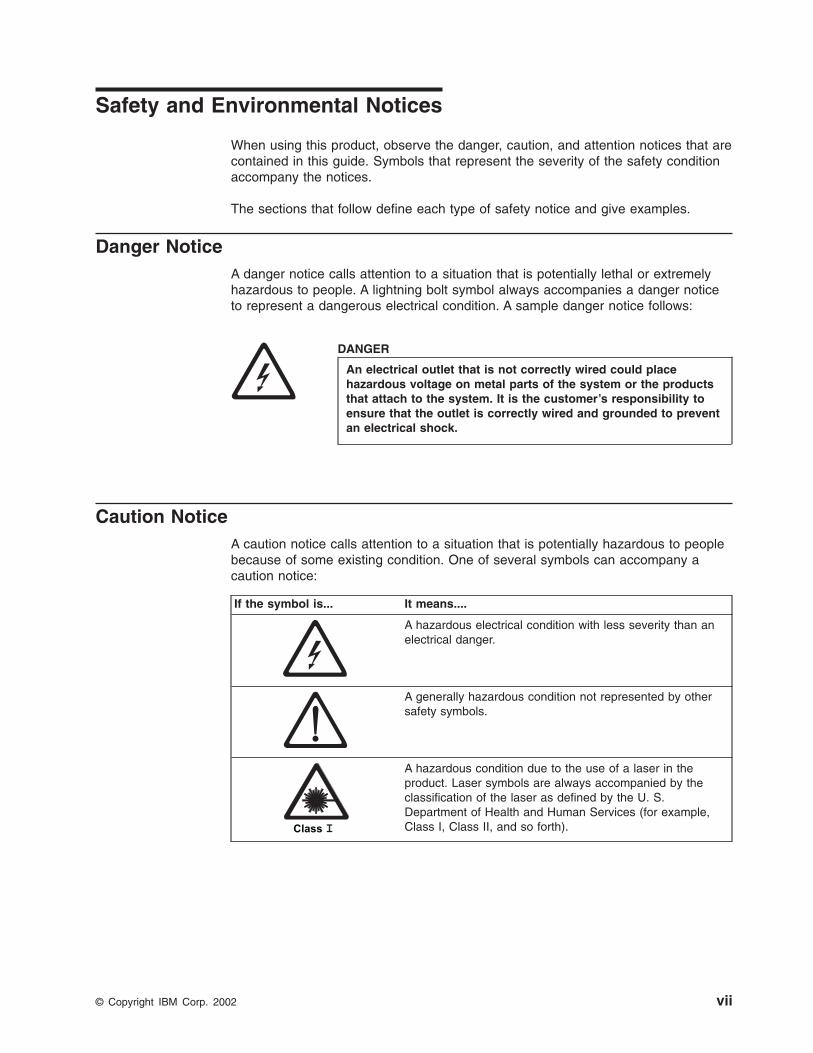
Danger NoticeA danger notice calls attention to a situation that is potentially lethal or extremelyhazardous to people. A lightning bolt symbol always accompanies a danger noticeto represent a dangerous electrical condition. A sample danger notice follows:
DANGER
An electrical outlet that is not correctly wired could placehazardous voltage on metal parts of the system or the productsthat attach to the system. It is the customer’s responsibility toensure that the outlet is correctly wired and grounded to preventan electrical shock.
Caution NoticeA caution notice calls attention to a situation that is potentially hazardous to peoplebecause of some existing condition. One of several symbols can accompany acaution notice:
If the symbol is... It means....
A hazardous electrical condition with less severity than anelectrical danger.
A generally hazardous condition not represented by othersafety symbols.
A hazardous condition due to the use of a laser in theproduct. Laser symbols are always accompanied by theclassification of the laser as defined by the U. S.Department of Health and Human Services (for example,Class I, Class II, and so forth).
© Copyright IBM Corp. 2002 vii
Sample caution notices follow:
CAUTION:The controller card contains a lithium battery. To avoid possibleexplosion, do not burn, exchange, or charge the battery. Discard thecontroller card as instructed by local regulations for lithiumbatteries.
CAUTION:Do not attempt to use the handle on the module to lift the entiredevice (module and enclosure) as a unit. First remove the module;then, use two hands to lift the enclosure.
Attention NoticeAn attention notice indicates the possibility of damage to a program, device, orsystem (server), or to data. An exclamation point symbol may accompany anattention notice, but is not required. Sample attention notices follow:
Attention: If you use a power screwdriver to perform thisprocedure it could destroy the tape.
Attention: Do not operate the Ultrium 2 Tape Drive in a poor air qualityenvironment.
Laser Safety and ComplianceThese products contain components that comply with performance standards thatare set by the U.S. Food and Drug Administration (Part 21CFR, 1040.10/11). Thismeans that these products belong to a class of laser products that do not emithazardous laser radiation. This classification was accomplished by providing thenecessary protective housing and scanning safeguards to ensure that laserradiation is inaccessible during operation or is within Class I limits. External safetyagencies have reviewed these products and have obtained approvals to the lateststandards as they apply to this product type.
viii IBM TotalStorage LTO Ultrium 2 Tape Drive

Preface
Intended AudienceThis book is intended primarily for integrators who install the IBM TotalStorage™
Linear Tape-Open (LTO) Ultrium 2 Tape Drive into an enclosure (such as a desktopunit, tape autoloader, or tape library). During operation of the enclosure, portions ofthe book may also be used by end users.
Related PublicationsRefer to the following publications for additional information about the Ultrium 2Tape Drive. To ensure that you have the latest publications, visit the web athttp://www.ibm.com/storage/lto.
IBM Ultrium Publicationsv IBM TotalStorage LTO Ultrium Tape Drive SCSI Reference, GA32-0450, provides
the supported SCSI commands and protocol that govern the behavior of theSCSI interface for all models of the IBM Ultrium Tape Drive.
v IBM TotalStorage LTO Ultrium 2 Tape Drive Quick Setup Guide, GX35-5066,illustrates how to configure and operate the IBM TotalStorage LTO Ultrium 2 TapeDrive.
v IBM Ultrium Device Drivers Installation and User’s Guide, GA32-0430, providesinstructions for attaching IBM-supported hardware to Open Systems operatingsystems. It indicates what devices and levels of operating systems aresupported, gives the requirements for adapter cards, and tells how to configureservers to use the device driver with the Ultrium family of devices.
v IBM Ultrium Device Drivers Programming Reference, GC35-0483, suppliesinformation to application owners who want to integrate their Open Systemsapplications with IBM-supported Ultrium hardware. The reference containsinformation about the application programming interfaces (APIs) for each of thevarious supported operating-system environments.
IBM Fibre Channel Publicationsv Fibre Channel Storage Hub IBM 2103 Model H07 Installation, Service, and
User’s Guide, SC26-7288
v IBM SAN Fibre Channel Switch 2109 Model S08 User’s Guide, SC26-7349
v IBM SAN Fibre Channel Switch 2109 Model S08 Installation and Service Guide,SC26-7350
v IBM SAN Fibre Channel Switch 2109 Model S16 User’s Guide, SC26-7351
v IBM SAN Fibre Channel Switch 2109 Model S16 Installation and Service Guide,SC26-7352
Other Publicationsv IBM Storage Area Network Gateway Module Setup, Operator, and Service Guide,
GA32-0436, describes the interface between devices and a storage area networkor Fibre Channel server. The guide gives instructions for installation andoperation of the unit, as well maintenance analysis procedures and a SCSIcommand reference.
v IBM Library/Drive Interface Specification, Revision 4.1, August 29, 2002,available from your OEM Sales Representative.
© Copyright IBM Corp. 2002 ix

x IBM TotalStorage LTO Ultrium 2 Tape Drive

Chapter 1. Introduction
The IBM TotalStorage Linear Tape-Open (LTO) Ultrium 2 Tape Drive is ahigh-performance, high-capacity data-storage device that is designed to backup andrestore Open Systems applications. The drive can be integrated into an enclosure,such as a desktop unit, tape autoloader, or tape library. The Ultrium 2 Tape Drive(called Generation 2) is the second-generation tape drive in the Ultrium series ofproducts. It is available as Model T400 with a Small Computer Systems Interface(SCSI) or as Model T400F with a Fibre Channel interface.
The Ultrium 2 Tape Drive offers the following features:
v Native storage capacity of up to 200 GB per cartridge (400 GB assuming 2:1LTO Data Compression)
v Native sustained data transfer rate of 35 MB per second (70 MB assuming 2:1LTO Data Compression)
Table 1 gives additional features for each model of the drive.
Table 1. Features of the IBM TotalStorage LTO Ultrium 2 Tape Drive
Model T400SCSI Interface
Model T400FFibre Channel Interface
Ultra160 Low Voltage Differential (LVD)Small Computer Systems Interface
SCSI protocol carried on a 2-Gb FibreChannel interface that supports switchedfabric, arbitrated loop, and point-to-pointtopologies
68-pin, D-shell connector (for SCSI signals,SCSI ID selection, and power connection)
LC-duplex, short-wave connector forattachment to Storage Area Network (SAN)components
Burst data transfer rate of 160 MB persecond
Burst data transfer rate of 200 MB persecond
Figure 1 shows a front view of the IBM TotalStorage LTO Ultrium 2 Tape Drive withand without a bezel.
Figure 1. View of the IBM TotalStorage LTO Ultrium 2 Tape Drive with and without the bezel
© Copyright IBM Corp. 2002 1

Cartridge CompatibilityThe Ultrium 2 Tape Drive (Generation 2) uses the IBM TotalStorage LTO Ultrium200 GB Data Cartridge and is compatible with the cartridges of its predecessor, theIBM Ultrium Internal Tape Drive (called Generation 1). The Ultrium 2 Tape Driveperforms the following functions:
v Reads and writes Generation 2 cartridges to Generation 2 format
v Reads and writes Generation 1 cartridges to Generation 1 format
v Does not write Generation 2 cartridges to Generation 1 format
v Does not write Generation 1 cartridges to Generation 2 format
The Ultrium 2 Tape Drive reads tapes that have been written by other licensedUltrium 2 drives. It also writes to tapes that can be read by other licensed Ultrium 2drives.
In addition to using the IBM TotalStorage LTO Ultrium Data Cartridge with up to 200GB capacity, the Ultrium 2 Tape Drive also offers read/write capability for certifiedLTO Ultrium tape cartridges.
Speed Matching and Channel CalibrationTo improve system performance, the Ultrium 2 Tape Drive uses a technique calledspeed matching to dynamically adjust its native (uncompressed) data rate to theslower data rate of a server. With speed matching, the drive operates at one of fivespeeds when reading or writing the Generation 2 cartridge format to achieve anative data rate of 17.5, 21.9, 26.25, 30.63, or 35 MB per second (MB/s). If theserver’s net (compressed) data rate is between two of the preceding native datarates, the drive calculates which of the two data rates at which to operate. (Forexample, if the server transfers data at 60 MB/s on the host bus, at 2:1compression its net data rate is 30 MB/s. The drive will then dynamically choose tooperate at a native data rate of 26.25 or 30.63 MB/s, whichever enables it tosuccessfully receive the greatest amount of compressed data over the network.)Speed matching dramatically reduces backhitch, the condition that occurs when atape stops, reverses, and restarts motion. A backhitch is usually the result of amismatch between the data rates of the server and the drive.
System performance is further optimized by a feature called channel calibration, inwhich the drive automatically customizes each read/write data channel tocompensate for variations in such things as the recording channel’s transferfunction, the media, and characteristics of the drive head.
Sleep ModeTo conserve energy when circuit functions are not needed for drive operation, theUltrium 2 Tape Drive features a power-management function that causes the drive’selectronics to enter a low-power mode known as sleep mode. To enter sleep mode,the drive must be inactive for a minimum of 15 minutes; to exit, the drive mustreceive a command across the SCSI or Fibre Channel interface, a command acrossthe Library/Drive Interface (LDI or RS-422 interface), or a load or unload request.When in sleep mode, the drive’s response time to commands that do not requiremedia motion increases by up to 10 microseconds. Commands that require mediamotion may be delayed an additional 100 milliseconds because the tape must beretensioned.
2 IBM TotalStorage LTO Ultrium 2 Tape Drive

Supported Servers and Operating SystemsThe Ultrium 2 Tape Drive attaches to the servers and operating systems shown inTable 2. Any attachment can include (but is not limited to) these servers andoperating systems. To determine the latest supported attachments, visit the web athttp://www.ibm.com/storage/lto. For specific instructions about attaching the tapedrive, see Chapter 3, “Installing the Tape Drive” on page 13.
Table 2. Supported servers and operating systems for SCSI and Fibre Channel attachment
Supported Servers Supported Operating Systems
IBM AS/400® or ERserver iSeries™ OS/400®
IBM RS/6000®, RS/6000 SP™, or Eserver
pSeries™AIX®
IBM Eserver zSeries™ 800 or 900 Linux
Hewlett-Packard HP-UX
Sun Microsystems Solaris
32-bit, Intel-compatible servers Microsoft®Windows® 2000 or Windows NT®
Red Hat Linux
64-bit, Intel Itanium servers Red Hat Linux
Supported SAN Components for Fibre Channel AttachmentVisit the web at: http://www.storage.ibm.com/hardsoft/tape/supserver/support.html
Chapter 1. Introduction 3

SCSI AttachmentTo communicate with a server, the IBM TotalStorage LTO Ultrium 2 Tape Drive usesthe Ultra160 LVD SCSI interface.
Physical Characteristics of the SCSI InterfaceThe Ultrium 2 Tape Drive contains a high-density, 68-pin, D-shell receptacleconnector (HD68) for attachment to the server. The HD68 connector includes theconnectors for the SCSI signal, the SCSI ID, and the drive’s power. The drivesupports LVD SCSI cables with HD68 connectors.
For a list of available cables, see Appendix A, “Tools and Supplies” on page 95.
SpeedThe Ultra160 LVD SCSI interface is backward compatible with older SCSItechnology and is capable of data transmission at 160 MB/s. Ultra160 SCSI usesthe three management features of the Ultra3 SCSI standard that specifically affectdata transfer rate:
v Double transition clocking - a data-transfer technique that enables data ratesto double without increasing clock speed
v Domain validation - a procedure that detects and adjusts SCSI configurationissues that might prevent interoperation between SCSI devices
v Cyclic redundancy check (CRC) - an error-checking technique
Because the cables, connectors, and terminators are the same for the Ultra160 andUltra2 SCSI interfaces, devices with those interfaces can be mixed on the samebus and each device can operate at its fully rated speed.
4 IBM TotalStorage LTO Ultrium 2 Tape Drive
Address AssignmentsEach device on a SCSI bus must have a SCSI identifier (ID) that identifies it to theserver. When you install the Ultrium 2 Tape Drive, you can specify its SCSI ID inone of three ways:
v By attaching jumpers to the SCSI ID connector
v By using your enclosure’s SCSI ID switch
v If you are installing the drive into a tape library, by setting the SCSI ID throughthe LDI or RS-422 interface
For more information, see “Setting the SCSI ID (SCSI Drive Only)” on page 17.
Installing, Removing, or Resetting a Drive on an Active SCSI BusYou can attach an Ultrium 2 Tape Drive to an active SCSI bus. However, thepreferred and safest method of adding, removing, or resetting a drive is to power-offthe system.
When adding, removing, or resetting a drive on an active SCSI bus, perform thefollowing steps:
1. Quiesce the drive. The drive to be added, removed, or reset must not beinvolved in any bus activity.
2. Disconnect power to the drive.
3. Connect or disconnect the SCSI bus cables to or from the drive’s SCSIconnector. Ensure that the SCSI bus remains intact from the server (initiator) tothe terminator throughout the connection or disconnection process.
Note: Changing or moving the terminator disrupts the continuity of the SCSIbus and interrupts any process on the bus.
Chapter 1. Introduction 5
Fibre Channel Attachment
Attention: A Class I laser assembly, in the optical transceiver, ismounted on the Ultrium Fibre Channel electronics card. This laserassembly is registered with the Department of Health and HumanServices and is in compliance with IEC825.
To communicate with a server, the Ultrium 2 Tape Drive has one Fibre Channelinterface (also called a port). In accordance with the standards of the AmericanNational Standards Institute (ANSI), the port runs Fibre Channel Protocol (whichincludes SCSI commands on the Fibre Channel) with ANSI-defined Fibre ChannelTape Support. The method by which the drive and server communicate isdetermined by the type of topology in which they reside and the type of connectionthat you choose.
Supported TopologiesThe Ultrium 2 Tape Drive can be attached in a two-node configuration, eitherdirectly to a switch as a public device (switched fabric) or directly to a host busadapter (HBA) as a private device. It can do so in a Point-to-Point topology (throughan N_port or F_port) or Arbitrated Loop topology (through an L_port or FL_port).
Unless you set the drive to force an explicit configuration (by using the FCconfiguration/status connector; see “Step 4. Change the Link Services of the Drive(optional)” on page 24), the Ultrium 2 Tape Drive automatically configures to anL_port or an N_port when it boots. The type of port to which it configures dependson whether the drive recognizes the connection as a loop or a point-to-pointconnection:
v An L_port supports a Fibre Channel Arbitrated Loop connection to an NL_port orFL_port.
v An N_port supports direct connection to another N_port or to an F_port (forexample, a director-class switch) in a point-to-point topology.
Regardless of the port to which you connect the drive, it automatically configures toa public device (through an F_port or FL_port to a switch) or to a private device(through an N_port or L_port by using direct attachment to a server).
Table 3 lists the topologies in which the Ultrium 2 Tape Drive can operate, the FibreChannel server connections that are available, and the port (NL, N, FL, or F)through which communication must occur.
Table 3. Choosing the port for your topology and Fibre Channel connection
Type of Topology
Type of Fibre Channel Connection to Server
Direct Connection(Private)
Switched Fabric(Public)
Fibre Channel-ArbitratedLoop(can be Two-Node ArbitratedLoop or Two-Node SwitchedFabric Loop; is limited to twonodes)
L_Port FL_Port
Point-to-Point(two nodes)
N_Port F_Port
6 IBM TotalStorage LTO Ultrium 2 Tape Drive
SpeedThe Ultrium 2 Tape Drive’s Fibre Channel interface facilitates data at 2 Gb/s (200MB/s). It automatically negotiates to a rate of 1 Gb/s (100 MB/s) if the system orswitch to which it connects does not support the 2-Gb rate (if this is the case, youmay experience performance degradation). You can force the drive to an explicitspeed by placing jumpers on the Fibre Channel (FC) configuration/status connector.For more information, see “Step 4. Change the Link Services of the Drive (optional)”on page 24.
Address AssignmentsEach device on a Fibre Channel loop must have a Loop Identifier (LID) and acorresponding Arbitrated Loop Physical Address (AL_PA) to communicate with otherdevices in the topology. The AL_PA identifies the device on the loop. (LIDs and theircorresponding AL_PAs are listed in Table 5 on page 21 and Table 6 on page 22.)You can set an AL_PA by using one of two methods known as soft addressing orhard addressing.
Soft addressing allows the drive to dynamically arbitrate the AL_PA with other FibreChannel devices on the loop. Hard addressing allows you to choose the LID, whichdetermines the corresponding AL_PA. The higher the AL_PA, the lower the priorityof the device.
Generally, servers (initiators) require that devices use hard addressing; they do notsupport soft addressing. When setting addresses, assign the lowest AL_PA (andthus the highest priority) to the server; assign the highest AL_PA (and thus thelowest priority) to the drive.
To set soft or hard addressing, you must place jumpers on designated pins in thedrive’s LID/status connector (see (�2� in Figure 3 on page 15). The pin configurationfor soft and hard addressing is defined in “Setting the Arbitrated Loop PhysicalAddress (Fibre Channel Drive Only)” on page 19.
Chapter 1. Introduction 7

World Wide NamesEach Ultrium 2 Tape Drive has an 8-byte World Wide Node Name and an 8-byteWorld Wide Port Name that is assigned by IBM Manufacturing. The World WideNode Name identifies the drive’s SCSI logical unit; the World Wide Port Nameidentifies the physical port on the drive. An enclosure queries the World WideNames through the LDI or RS-422 interface; a server queries the Names throughthe Fibre Channel interface. The Ultrium 2 Tape Drive reports the World WideNames to switches. You can use the World Wide Node Name or Wide Node PortName to uniquely identify the drive on a SAN.
When your Ultrium 2 Tape Drive is installed in a tape library, you can change theWorld Wide Node Name and World Wide Port Name through the LDI or RS-422interface. For instructions, refer to the documentation for your tape library.
Physical Characteristics of the Fibre Channel InterfaceThe Ultrium 2 Tape Drive attaches to Open Systems servers by using short-wave,multimode fiber optic cables. All cables feature LC-duplex connectors and aredesignated as 50/125 (50 refers to the diameter of the optical fiber and 125 refersto the diameter of the cable; both are measured in micrometers).
For a list of available cables, see Appendix A, “Tools and Supplies” on page 95.
Installing, Removing, or Resetting a Drive on an Active Fibre ChannelA Fibre Channel network supports dynamic drive attachment. When adding,removing, or resetting a drive on an active server or SAN, perform the followingsteps:
1. Quiesce the drive. The drive to be added, removed, or reset must not beinvolved in activity.
2. Connect or disconnect the Fibre Channel cables to or from the drive.
8 IBM TotalStorage LTO Ultrium 2 Tape Drive
Supported Device DriversIBM offers device drivers for the Ultrium 2 Tape Drive. Device drivers enable thedrive to interact with a variety of servers. To properly install an IBM device driver (ifrequired), refer to the IBM Ultrium Device Drivers Installation and User’s Guide. Forapplications that use other device drivers, see the application’s documentation todetermine which drivers to use.
IBM maintains the latest levels of device drivers and driver documentation for theIBM TotalStorage LTO Ultrium 2 Tape Drive on the Internet. You can access thismaterial from your browser or through the IBM FTP site by performing one of thefollowing procedures. (Note: If you do not have Internet access and you needinformation about device drivers, contact your Marketing Representative.)
v Using a browser, type one of the following:
– http://www.ibm.com/storage
– ftp://ftp.software.ibm.com/storage/devdrvr
– ftp://207.25.253.26/storage/devdrvr
v Using an IBM FTP site, enter the following specifications:
– FTP site: ftp.software.ibm.com
– IP Addr: 207.25.253.26
– Userid: anonymous
– Password: (use your current e-mail address)
– Directory: /storage/devdrvr
IBM provides PostScript- and PDF-formatted versions of its documentation in the/storage/devdrvr/doc directory:
v IBM_ultrium_tape_IUG.ps and IBM_ultrium_tape_IUG.pdf contain the currentversion of the IBM Ultrium Device Drivers Installation and User’s Guide
v IBM_ultrium_tape_PROGREF.ps and IBM_ultrium_tape_PROGREF.pdf containthe current version of the IBM Ultrium Device Drivers Programming Reference
Device drivers and utilities for each supported server are beneath /storage/devdrvr/in the following directories (the device driver for the iSeries or AS/400 server isincluded in the OS/400 operating system):
v AIX
v HPUX
v Linux
v Solaris
v Tru64
v WinNT
v Win2000
For more information about device drivers, refer to any of the preceding directories.
Chapter 1. Introduction 9

10 IBM TotalStorage LTO Ultrium 2 Tape Drive

Chapter 2. Specifications
Table 4 gives the physical, power, and environmental specifications for the IBMTotalStorage LTO Ultrium 2 Tape Drive. Specifications for tape cartridges are givenin “Environmental and Shipping Specifications for Tape Cartridges” on page 62.
Table 4. Specifications for the IBM TotalStorage LTO Ultrium 2 Tape Drive
Specification Measurement
Physical Specifications
Width 146.0 mm (5.75 in.) without bezel
148.3 mm (5.84 in.) with bezel
Length 205.5 mm (8.09 in.) without bezel
210.5 mm (8.29 in.) with bezel
Height 82.5 mm (3.25 in.) without bezel
84.8 mm (3.34 in.) with bezel
Weight (without a cartridge) 3 kg (6 lb 10 oz)
Power Specifications
Drive with Ultra160 SCSI Interface Drive with Fibre Channel Interface
Tolerance (see Note 1) + 5 Vdc and + 12 Vdc (±10%) + 5 Vdc and + 12 Vdc (±10%)
Power supply current for 5Vdc (see Note 2)
1.3 A minimum 1.9 A minimum
3.1 A maximum 3.7 A maximum
Power supply current for 12Vdc (see Note 2)
0.2 A minimum 0.2 A minimum
1.1 A maximum 1.1 A maximum
Power supply peak for 5Vdc (the instantaneouspower by the power supply)
3.3 A for 100 ms15.5 W
3.9 A for 100 ms19.5 W
Power supply peak for 12Vdc (the instantaneouspower by the power supply)
4.1 A for 2 ms49.2 W
4.1 A for 2 ms49.2 W
Power usage for typical idlemode with no cartridge
10.9 W 13.9 W
Power usage for typical idlemode with a cartridgeloaded
12.7 W 15.7 W
Power usage for readingand writing at 6.22 m/s
29 W 32 W
Power usage for sleepmode with no cartridge
9.0 W 12.0 W
Power usage for sleepmode with a cartridgeloaded
10.8 W 13.8 W
Other Specifications (for both interface types)
Maximum altitude 3048 m (10,000 ft) for operating and storage
12192 m (40,000 ft) for shipping
Extraction force 250 to 750 gms-force
© Copyright IBM Corp. 2002 11

Table 4. Specifications for the IBM TotalStorage LTO Ultrium 2 Tape Drive (continued)
Environmental Specifications (for both interface types)
Environmental FactorOperating
(see Note 3)Storage Shipping
Drive temperature10 to 40°C
(50 to 104°F)1 to 60°C
(33.8 to 140°F)−40 to 60°C
(−40 to 140°F)
Relative humidity(noncondensing)
20 to 80% 10 to 90% 10 to 90%
Wet bulb temperature26°C
(78.8°F)26°C
(78.8°F)26°C
(78.8°F)
Notes:
1. Measured at the drive’s power connector.
2. The + 5 Vdc and + 12 Vdc maximum currents do not occur simultaneously. The Ultrium 2 Tape Drive monitorsvoltage and reports problems to the server.
3. Measured in front of the bezel, near the air intake area (refer to Figure 4 on page 16).
12 IBM TotalStorage LTO Ultrium 2 Tape Drive

Chapter 3. Installing the Tape Drive
Attention:To avoid static electricity damage when you handle the IBM TotalStorage LTOUltrium 2 Tape Drive, use the following precautions:
v Limit your movement. Movement can cause static electricity to build aroundyou.
v Always handle the Ultrium 2 Tape Drive carefully. Never touch exposedcircuitry.
v Prevent others from touching the Ultrium 2 Tape Drive.
v Before you unpack and install the Ultrium 2 Tape Drive into an enclosure,touch its static-protective packaging to an unpainted metal surface on theenclosure for at least 2 seconds. This reduces static electricity in thepackaging and your body.
v When possible, remove the Ultrium 2 Tape Drive from its static-protectivepackaging and install it directly into an enclosure without setting it down.When this is not possible, place the tape drive’s packaging on a smooth,level surface and place the tape drive on the packaging.
v Do not place the Ultrium 2 Tape Drive on the cover of the enclosure or onany other metal surface.
The steps that follow describe how to install the Ultrium 2 Tape Drive into anenclosure.
Note: Depending on the type of enclosure, installation procedures may vary. Beforestarting this installation, read these instructions and compare them to thedrive installation instructions for your enclosure.
When installing the Ultrium 2 Tape Drive into an enclosure, refer to “Rear View ofthe SCSI Drive” on page 14 or “Rear View of the Fibre Channel Drive” on page 15.
© Copyright IBM Corp. 2002 13

Rear View of the SCSI Drive�1� Feature switches
�2� SCSI connector
�3� SCSI ID connector
�4� Power connector
�5� Library/Drive Interface (LDI or RS-422 interface) connector
Figure 2. Rear view of the IBM TotalStorage LTO Ultrium 2 Tape Drive Model T400 (SCSIdrive)
14 IBM TotalStorage LTO Ultrium 2 Tape Drive
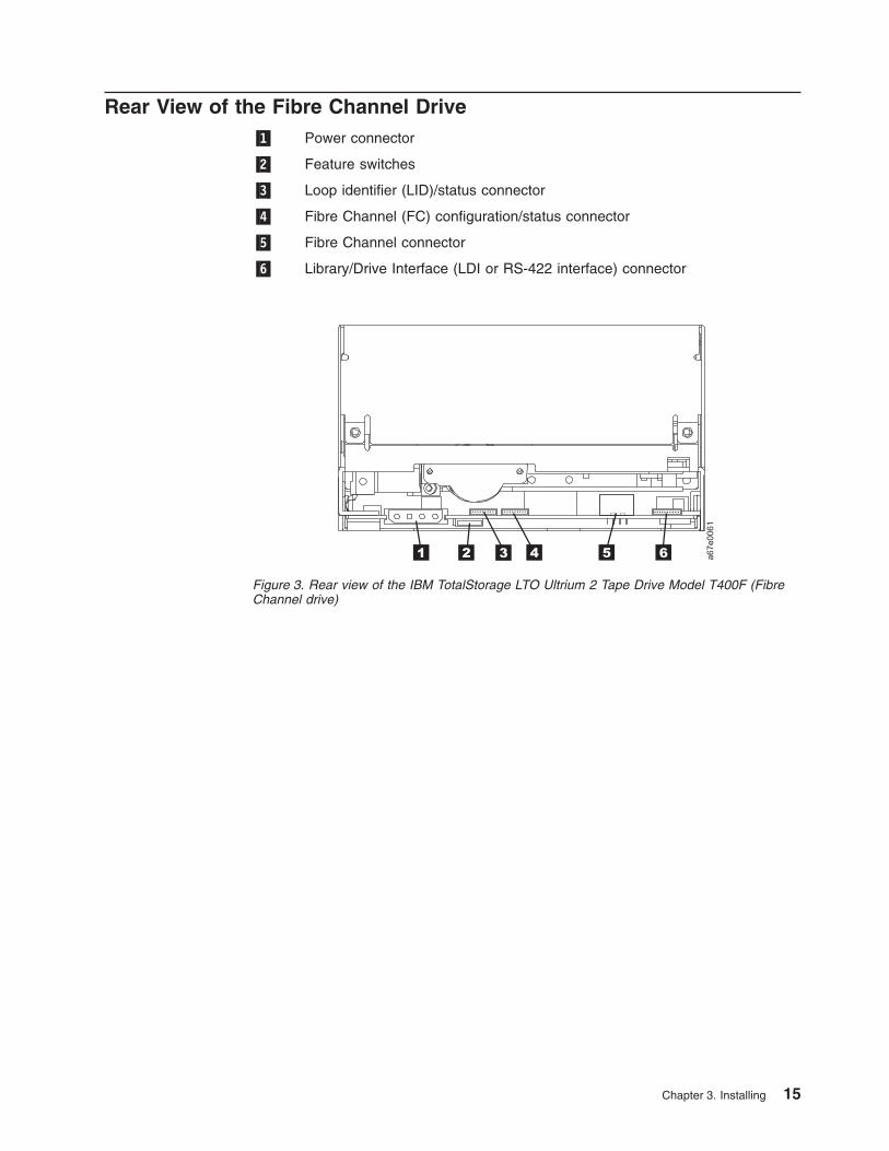
Rear View of the Fibre Channel Drive�1� Power connector
�2� Feature switches
�3� Loop identifier (LID)/status connector
�4� Fibre Channel (FC) configuration/status connector
�5� Fibre Channel connector
�6� Library/Drive Interface (LDI or RS-422 interface) connector
Figure 3. Rear view of the IBM TotalStorage LTO Ultrium 2 Tape Drive Model T400F (FibreChannel drive)
Chapter 3. Installing 15

Step 1. Unpack the DriveUnpack the Ultrium 2 Tape Drive and store the packaging. You may need thepackaging if you return the unit for service.
Attention::
Acclimation time is required if the temperature of the drive when unpacked isdifferent than the temperature of its operating environment (measured at the front ofthe bezel near the air intake area; see Figure 4). The recommended acclimationtime is 4 hours after the drive has been unpacked or 1 hour after any condensationthat you can see has evaporated, whichever is greater. When acclimatizing thedrive, apply the following measures:
v If the drive is colder than its operating environment and the air contains sufficienthumidity, condensation may occur in the drive and damage it. When the drivehas warmed to the operating temperature range (greater than 10°C or 50°F) andno danger of condensation is present (the air is dry), warm the drive more quicklyby powering it on for 30 minutes. Use a diagnostic tape to test the drive beforeinserting a tape that contains data.
v If the drive is hotter than its operating environment, the tape can stick to the drivehead. When the drive has cooled to the operating temperature range (less than40°C or 104°F), cool the drive more quickly by applying airflow for 30 minutes.Power-on the drive and use a diagnostic tape to test it before inserting a tapethat contains data.
If you are uncertain about whether the temperature of the drive is within therecommended operating range or the humidity is sufficient to cause condensation,acclimate the drive for the full 4 hours.
Step 2. Remove Power from the Enclosure__ 1. Power-off the enclosure (or the unit that provides power to the drive)
__ 2. Disconnect the power cord from both the electrical outlet and the enclosure.
Figure 4. Measuring the temperature of the operating environment. The temperature ismeasured at the front of the bezel, near the air intake area.
16 IBM TotalStorage LTO Ultrium 2 Tape Drive
Step 3. Set the SCSI ID or Arbitrated Loop Physical AddressPerform one of the following steps:
v If you are installing an Ultrium 2 Tape Drive that uses a SCSI interface (ModelT400), you must set the drive’s SCSI ID. For instructions, go to “Setting the SCSIID (SCSI Drive Only)” on this page.
v If you are installing an Ultrium 2 Tape Drive that uses a Fibre Channel interface(Model T400F), you must set the drive’s Arbitrated Loop Physical Address(AL_PA). For instructions, go to “Setting the Arbitrated Loop Physical Address(Fibre Channel Drive Only)” on page 19.
Setting the SCSI ID (SCSI Drive Only)You can set the SCSI ID in one of three ways:
v By placing jumpers on the SCSI ID connector
v By using a SCSI ID switch that is connected to the SCSI ID connector
v By issuing a command from the library to set the SCSI ID through the drive’s LDIinterface
The sections that follow describe each method of setting the SCSI ID.
Setting the SCSI ID with JumpersYou can set the SCSI ID on the Ultrium 2 Tape Drive by installing 2-mm jumpers onthe drive’s SCSI ID connector (see �3� in Figure 2 on page 14). Your tape drivemay come set to a default SCSI configuration, with jumpers already installed. Tochange the default SCSI configuration, contact your sales or or technical supportrepresentative. You can change the SCSI ID by rearranging, adding, or removingjumpers.
To set the SCSI ID:
__ 1. Locate the SCSI ID connector (see �3� in Figure 2 on page 14).
__ 2. Before attaching the SCSI bus cable to the server, decide the SCSI IDnumber that you want. Make sure that the ID is not being used by anotherdevice.
__ 3. Referring to Figure 5 on page 18, find the ID number that you chose thenplace jumpers on the connector pins as shown (use a pair of needle-nosepliers to connect the jumpers to the pins that are shaded).
Note: If you set the SCSI ID to 15, the drive will not necessarily be set tothat ID; instead, the drive will expect to receive the SCSI ID through acommand over its LDI interface.
Chapter 3. Installing 17

Setting the SCSI ID with a SCSI ID SwitchIf your enclosure uses a SCSI ID switch (rather than jumpers), connect the switchto the drive’s SCSI ID connector (see �3� in Figure 2 on page 14). If any jumpersare pre-installed, be sure to remove them before connecting the switch. The SCSIID switch must be compatible with the drive’s SCSI ID connector and must make anelectrical connection between the same pins as the jumpers to achieve the samecorresponding SCSI ID.
Setting the SCSI ID Through the LDI InterfaceIf you are installing the Ultrium 2 Tape Drive into a tape library, you can issue acommand from the library to set the drive’s SCSI ID through the LDI interface.Make sure that the SCSI ID is set to 15 (see Figure 5). When configured to acceptits SCSI ID through the LDI interface, the drive does not respond to SCSIcommands until it receives a Set Configuration command through the interface.
Supplying TERMPOWER (SCSI Drive Only)To supply TERMPOWER to the bus, locate one of the five jumpers shipped with theUltrium 2 Tape Drive and place it on the SCSI ID connector as shown in thefollowing figure. Place the jumper on the pins that are shaded.
A67E
0049
Note that you must provide SCSI termination externally to the Ultrium 2 Tape Drive.
Figure 5. SCSI ID settings on the SCSI ID connector
18 IBM TotalStorage LTO Ultrium 2 Tape Drive
Setting the Arbitrated Loop Physical Address (Fibre Channel DriveOnly)
Each device on a Fibre Channel loop must have an Arbitrated Loop PhysicalAddress (AL_PA) to communicate. The AL_PA identifies the device on the loop. Toset the Ultrium 2 Tape Drive’s AL_PA, you must place jumpers on specific pins inthe drive’s loop identifier (LID)/status connector. The placement of the jumpersindicates whether you want to choose the LID yourself (each LID corresponds to aspecific AL_PA) or whether you want the drive to choose the AL_PA by arbitrating itwith other devices on the loop. Valid LIDs and their corresponding AL_PAs areprovided in this section.
Note: A Loop ID is part of a contiguous range of values; valid AL_PA values arenot in a contiguous range.
In addition to establishing the AL_PA, by moving Feature Switch 3 on the drive toON or off you can set the drive so that it provides one of the following functions:
v Status about the Fibre Channel loop (through the use of external indicators in anenclosure)
v Additional LIDs
The sections that follow describe how to select the AL_PA. They also describe howto set Feature Switch 3 so that the drive gives status about the loop or providesadditional LIDs.
Chapter 3. Installing 19
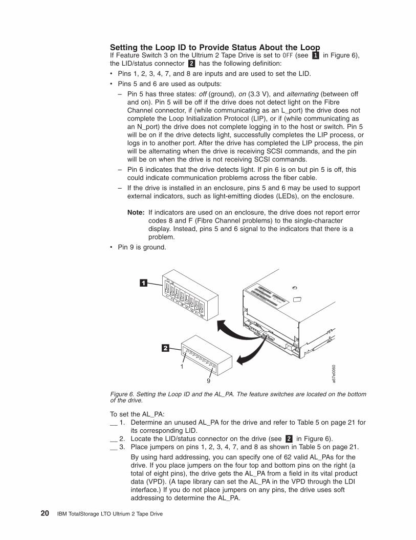
Setting the Loop ID to Provide Status About the LoopIf Feature Switch 3 on the Ultrium 2 Tape Drive is set to OFF (see �1� in Figure 6),the LID/status connector �2� has the following definition:
v Pins 1, 2, 3, 4, 7, and 8 are inputs and are used to set the LID.
v Pins 5 and 6 are used as outputs:
– Pin 5 has three states: off (ground), on (3.3 V), and alternating (between offand on). Pin 5 will be off if the drive does not detect light on the FibreChannel connector, if (while communicating as an L_port) the drive does notcomplete the Loop Initialization Protocol (LIP), or if (while communicating asan N_port) the drive does not complete logging in to the host or switch. Pin 5will be on if the drive detects light, successfully completes the LIP process, orlogs in to another port. After the drive has completed the LIP process, the pinwill be alternating when the drive is receiving SCSI commands, and the pinwill be on when the drive is not receiving SCSI commands.
– Pin 6 indicates that the drive detects light. If pin 6 is on but pin 5 is off, thiscould indicate communication problems across the fiber cable.
– If the drive is installed in an enclosure, pins 5 and 6 may be used to supportexternal indicators, such as light-emitting diodes (LEDs), on the enclosure.
Note: If indicators are used on an enclosure, the drive does not report errorcodes 8 and F (Fibre Channel problems) to the single-characterdisplay. Instead, pins 5 and 6 signal to the indicators that there is aproblem.
v Pin 9 is ground.
To set the AL_PA:__ 1. Determine an unused AL_PA for the drive and refer to Table 5 on page 21 for
its corresponding LID.__ 2. Locate the LID/status connector on the drive (see �2� in Figure 6).__ 3. Place jumpers on pins 1, 2, 3, 4, 7, and 8 as shown in Table 5 on page 21.
By using hard addressing, you can specify one of 62 valid AL_PAs for thedrive. If you place jumpers on the four top and bottom pins on the right (atotal of eight pins), the drive gets the AL_PA from a field in its vital productdata (VPD). (A tape library can set the AL_PA in the VPD through the LDIinterface.) If you do not place jumpers on any pins, the drive uses softaddressing to determine the AL_PA.
Figure 6. Setting the Loop ID and the AL_PA. The feature switches are located on the bottomof the drive.
20 IBM TotalStorage LTO Ultrium 2 Tape Drive

Table 5. ID Settings that provide status about the loop. The table lists the AL_PAs, corresponding LIDs, anddefinitions of the jumpers on the connector pins. Feature Switch 3 must be set to OFF.
AL_PA LID
Pin(see Notes) AL_PA LID
Pin(see Notes)
1 2 3 4 7 8 1 2 3 4 7 8
use softaddressing
0 - - - - - - B2 20 G - - - - -
E8 1 - - - - - G B1 21 G - - - - G
E4 2 - - - - G - AE 22 G - - - G -
E2 3 - - - - G G AD 23 G - - - G G
E1 4 - - - G - - AC 24 G - - G - -
E0 5 - - - G - G AB 25 G - - G - G
DC 6 - - - G G - AA 26 G - - G G -
DA 7 - - - G G G A9 27 G - - G G G
D9 8 - - G - - - A7 28 G - G - - -
D6 9 - - G - - G A6 29 G - G - - G
D5 A - - G - G - A5 2A G - G - G -
D4 B - - G - G G A3 2B G - G - G G
D3 C - - G G - - 9F 2C G - G G - -
D2 D - - G G - G 9E 2D G - G G - G
D1 E - - G G G - 9D 2E G - G G G -
CE F - - G G G G 9B 2F G - G G G G
CD 10 - G - - - - 98 30 G G - - - -
CC 11 - G - - - G 97 31 G G - - - G
CB 12 - G - - G - 90 32 G G - - G -
CA 13 - G - - G G 8F 33 G G - - G G
C9 14 - G - G - - 88 34 G G - G - -
C7 15 - G - G - G 84 35 G G - G - G
C6 16 - G - G G - 82 36 G G - G G -
C5 17 - G - G G G 81 37 G G - G G G
C3 18 - G G - - - 80 38 G G G - - -
BC 19 - G G - - G 7C 39 G G G - - G
BA 1A - G G - G - 7A 3A G G G - G -
B9 1B - G G - G G 79 3B G G G - G G
B6 1C - G G G - - 76 3C G G G G - -
B5 1D - G G G - G 75 3D G G G G - G
B4 1E - G G G G - 74 3E G G G G G -
B3 1F - G G G G Guse AL_PAfrom VPD
3F G G G G G G
Notes:
1. G means that the pin is jumpered to ground.
2. - means that the pin is not jumpered.
Chapter 3. Installing 21

Setting the Loop ID to Provide Additional Loop IDsIf Feature Switch 3 on the Ultrium 2 Tape Drive is set to ON (see �1� in Figure 6 onpage 20), the LID/status connector �2� has the following definition:
v Pins 1 through 7 are used to set the LID.
v Pin 8 overrides pins 1 through 7. If you place a jumper on pin 8, the drive usesits vital product data (VPD) to set the AL_PA. A tape library can set the AL_PA inVPD through the LDI interface.
v Pin 9 is ground.
Note: Feature Switch 3 does not support LEDs on an enclosure. Therefore, whenFeature Switch 3 is set to ON, the drive can report Fibre Channel problems(error codes 8 and F) on the single-character display, but not by using theenclosure’s external indicators.
To set the AL_PA:__ 1. Determine an unused AL_PA address for the drive and refer to Table 6 for its
corresponding LID.__ 2. Locate the LID/status connector on the drive (see �2� in Figure 6 on
page 20).__ 3. Place jumpers on pins 1 through 7 as shown in Table 6 or on pin 8.
Table 6. ID settings that provide additional Loop IDs. The table lists the AL_PAs, corresponding LIDs, and definitionsof the jumpers on the connector pins. Feature Switch 3 must be set to ON.
AL_PA LID
Pin(see Notes) AL_PA LID
Pin(see Notes)
1 2 3 4 5 6 7 1 2 3 4 5 6 7
EF 0 - - - - - - - B1 21 - G - - - - G
E8 1 - - - - - - G AE 22 - G - - - G -
E4 2 - - - - - G - AD 23 - G - - - G G
E2 3 - - - - - G G AC 24 - G - - G - -
E1 4 - - - - G - - AB 25 - G - - G - G
E0 5 - - - - G - G AA 26 - G - - G G -
DC 6 - - - - G G - A9 27 - G - - G G G
DA 7 - - - - G G G A7 28 - G - G - - -
D9 8 - - - G - - - A6 29 - G - G - - G
D6 9 - - - G - - G A5 2A - G - G - G -
D5 A - - - G - G - A3 2B - G - G - G G
D4 B - - - G - G G 9F 2C - G - G G - -
D3 C - - - G G - - 9E 2D - G - G G - G
D2 D - - - G G - G 9D 2E - G - G G G -
D1 E - - - G G G - 9B 2F - G - G G G G
CE F - - - G G G G 98 30 - G G - - - -
CD 10 - - G - - - - 97 31 - G G - - - G
CC 11 - - G - - - G 90 32 - G G - - G -
CB 12 - - G - - G - 8F 33 - G G - - G G
CA 13 - - G - - G G 88 34 - G G - G - -
C9 14 - - G - G - - 84 35 - G G - G - G
C7 15 - - G - G - G 82 36 - G G - G G -
C6 16 - - G - G G - 81 37 - G G - G G G
22 IBM TotalStorage LTO Ultrium 2 Tape Drive

Table 6. ID settings that provide additional Loop IDs (continued). The table lists the AL_PAs, corresponding LIDs,and definitions of the jumpers on the connector pins. Feature Switch 3 must be set to ON.
AL_PA LID
Pin(see Notes) AL_PA LID
Pin(see Notes)
1 2 3 4 5 6 7 1 2 3 4 5 6 7
C5 17 - - G - G G G 80 38 - G G G - - -
C3 18 - - G G - - - 7C 39 - G G G - - G
BC 19 - - G G - - G 7A 3A - G G G - G -
BA 1A - - G G - G - 79 3B - G G G - G G
B9 1B - - G G - G G 76 3C - G G G G - -
B6 1C - - G G G - - 75 3D - G G G G - G
B5 1D - - G G G - G 74 3E - G G G G G -
B4 1E - - G G G G - 73 3F - G G G G G G
B3 1F - - G G G G G 72 40 G - - - - - -
B2 20 - G - - - - - 71 41 G - - - - - G
6E 42 G - - - - G - 39 61 G G - - - - G
6D 43 G - - - - G G 36 62 G G - - - G -
6C 44 G - - - - G - 35 63 G G - - - G G
6B 45 G - - - G - G 34 64 G G - - G - -
6A 46 G - - - G G - 33 65 G G - - G - G
69 47 G - - - G G G 32 66 G G - - G G -
67 48 G - - G - - - 31 67 G G - - G G G
66 49 G - - G - - G 2E 68 G G - G - - -
65 4A G - - G - G - 2D 69 G G - G - - G
63 4B G - - G - G G 2C 6A G G - G - G -
5C 4C G - - G G - - 2B 6B G G - G - G G
5A 4D G - - G G - G 2A 6C G G - G G - -
59 4E G - - G G G - 29 6D G G - G G - G
56 4F G - - G G G G 27 6E G G - G G G -
55 50 G - G - - - - 26 6F G G - G G G G
54 51 G - G - - - G 25 70 G G G - - - -
53 52 G - G - - G - 23 71 G G G - - - G
52 53 G - G - - G G 1F 72 G G G - - G -
51 54 G - G - G - - 1E 73 G G G - - G G
4E 55 G - G - G - G 1D 74 G G G - G - -
4D 56 G - G - G G - 1B 75 G G G - G - G
4C 57 G - G - G G G 18 76 G G G - G G -
4B 58 G - G G - - - 17 77 G G G - G G G
4A 59 G - G G - - G 10 78 G G G G - - -
49 5A G - G G - G - 0F 79 G G G G - - G
47 5B G - G G - G G 08 7A G G G G - G -
46 5C G - G G G - - 04 7B G G G G - G G
45 5D G - G G G - G 02 7C G G G G G - -
43 5E G - G G G G - 01 7D G G G G G - G
Chapter 3. Installing 23

Table 6. ID settings that provide additional Loop IDs (continued). The table lists the AL_PAs, corresponding LIDs,and definitions of the jumpers on the connector pins. Feature Switch 3 must be set to ON.
AL_PA LID
Pin(see Notes) AL_PA LID
Pin(see Notes)
1 2 3 4 5 6 7 1 2 3 4 5 6 7
3C 5F G - G G G G G SA 7E G G G G G G -
3A 60 G G - - - - - SA 7F G G G G G G G
Notes:
1. G means that the pin is jumpered to ground.
2. - means that the pin is not jumpered.
3. SA means soft addressing.
Step 4. Change the Link Services of the Drive (optional)You can optionally change the link services (for example, the speed and type oftopology) of your Fibre Channel drive. If you choose not to alter the link services,the drive defaults to a negotiated speed and operation in an FC-AL topology with adirect connection to the server.
In the following procedure, note that:
v Pin 5 is disconnected and is not represented in Table 7.
v Pin 9 is ground.
To change the type of topology and the speed of the Fibre Channel drive:__ 1. Determine the type of topology in which you want to operate the Ultrium 2
Tape Drive and refer to Table 7 for its corresponding pin configuration.__ 2. Determine the speed at which you want the Ultrium 2 Tape Drive to operate
and refer to Table 7 for its corresponding pin configuration.__ 3. Locate the Fibre Channel (FC) configuration/status connector on the drive
(see �1� in Figure 7 on page 25).__ 4. Place jumpers on the pins that you identified in steps 1 and 2.
Table 7. Topology and speed settings for the Ultrium 2 Tape Drive
Fibre ChannelCharacteristic
Pin
1 2 3 4 5 through 8
Speed Selection
Drive uses VPD values thatcan be updated by the LDIor RS-422 (the defaultvalue is Negotiated)
- - X X X
2 Gb (200 MB/s) - G X X X
1 Gb (100 MB/s) G - X X X
Negotiated (the driveautomatically negotiates tothe highest common speed)
G G X X X
Topology Selection
Drive uses VPD values thatcan be updated by the LDIor RS-422 (the defaultvalue is the NL_port)
X X - - X
24 IBM TotalStorage LTO Ultrium 2 Tape Drive
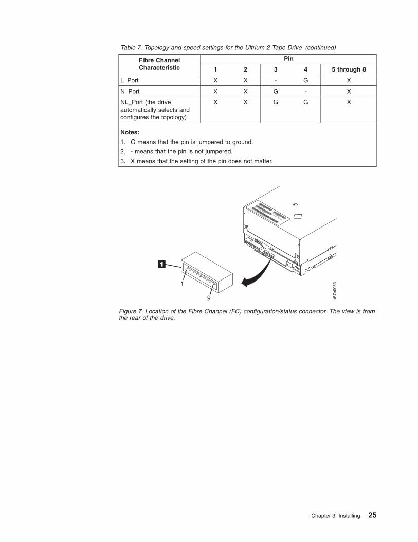
Table 7. Topology and speed settings for the Ultrium 2 Tape Drive (continued)
Fibre ChannelCharacteristic
Pin
1 2 3 4 5 through 8
L_Port X X - G X
N_Port X X G - X
NL_Port (the driveautomatically selects andconfigures the topology)
X X G G X
Notes:
1. G means that the pin is jumpered to ground.
2. - means that the pin is not jumpered.
3. X means that the setting of the pin does not matter.
Figure 7. Location of the Fibre Channel (FC) configuration/status connector. The view is fromthe rear of the drive.
Chapter 3. Installing 25
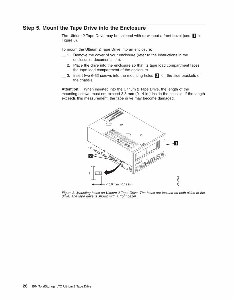
Step 5. Mount the Tape Drive into the EnclosureThe Ultrium 2 Tape Drive may be shipped with or without a front bezel (see �1� inFigure 8).
To mount the Ultrium 2 Tape Drive into an enclosure:
__ 1. Remove the cover of your enclosure (refer to the instructions in theenclosure’s documentation).
__ 2. Place the drive into the enclosure so that its tape load compartment facesthe tape load compartment of the enclosure.
__ 3. Insert two 6-32 screws into the mounting holes �2� on the side brackets ofthe chassis.
Attention: When inserted into the Ultrium 2 Tape Drive, the length of themounting screws must not exceed 3.5 mm (0.14 in.) inside the chassis. If the lengthexceeds this measurement, the tape drive may become damaged.
Figure 8. Mounting holes on Ultrium 2 Tape Drive. The holes are located on both sides of thedrive. The tape drive is shown with a front bezel.
26 IBM TotalStorage LTO Ultrium 2 Tape Drive

Step 6. Connect and Test Power to the Tape DriveThe Ultrium 2 Tape Drive does not contain its own power source; it must bepowered externally.
To connect and test power to the Ultrium 2 Tape Drive:
__ 1. Ensure that the enclosure (or unit that supplies power to the drive) ispowered off.
__ 2. Ensure that the power cord is disconnected from both the enclosure and thepower outlet.
__ 3. Connect the enclosure’s internal power cable to the power connector on thedrive (if you are using a SCSI drive, see �4� in Figure 2 on page 14; if youare using Fibre Channel drive, see �1� in Figure 3 on page 15). Ensure thatthe connector is properly connected.
__ 4. Connect the power cord to the enclosure and to the electrical outlet.
__ 5. Review the location of the single-character display and the status light onpage 31 (if your drive does not have a bezel, note that the bulb of the statuslight is recessed and the light is not visible until lit). To ensure that the driveis receiving power, watch for the following while turning on the power to theenclosure:
v The single-character display presents a series of random characters, thenbecomes blank (not lit).
Note: If the single-character display does not come on, the drivemay not be getting power.
v The status light briefly becomes solid amber, then becomes solid green.
__ 6. Power-off the enclosure.
__ 7. Disconnect the power cord from both the enclosure and the electrical outlet.
Step 7. Connect the Internal SCSI or Fibre Channel Cable__ 1. Perform one of the following procedures:
v If you are using a SCSI drive (Model T400), connect the enclosure’sinternal SCSI cable to the SCSI connector on the drive (see �2� inFigure 2 on page 14).
v If you are using a Fibre Channel drive (Model T400F), connect theenclosure’s internal Fibre Channel cable to the Fibre Channel connectoron the drive (see �5� in Figure 3 on page 15).
__ 2. Ensure that the connector is properly connected.
Chapter 3. Installing 27
Step 8. Connect the Internal LDI Cable (optional)
Note: Use this step only if you are installing the Ultrium 2 Tape Drive into a librarycontrol system. The drive uses the Library/Drive Interface (LDI) tocommunicate with a tape library.
Connect the enclosure’s internal LDI cable to the LDI connector on the drive (see�5� in Figure 2 on page 14 or �6� in Figure 3 on page 15).
Step 9. Run Drive Diagnostics__ 1. Replace the cover on the enclosure.
__ 2. Connect the power cord to both the enclosure and the electrical outlet, thenpower-on the enclosure.
__ 3. Run one or more of the following tape drive diagnostics. If an error codeappears on the single-character display, go to Table 15 on page 67.
v Function Code 1 - Run Tape Drive Diagnostics (see page 36).
v Function Code 6 - Run Wrap Test (for a SCSI drive, see page 39; for aFibre Channel drive, see page 40).
v Function Code 7 - Run LDI Wrap Test (see page 41).
__ 4. Power-off the enclosure, then disconnect the power cord from both theenclosure and the electrical outlet.
Step 10. Install the Device DriversFor information about installing device drivers, refer to the documentation for yourenclosure.
Step 11. Connect the External SCSI or Fibre Channel Interface to theServer
Perform one of the following steps:
v If you are using a SCSI drive (Model T400), connect the enclosure’s externalSCSI cable to the SCSI connector on the server. For instructions, go to “Connectthe External SCSI Interface to the Server” on this page.
v If you are using a Fibre Channel drive (Model T400F), connect the enclosure’sexternal Fibre Channel cable to the Fibre Channel connector on the server. Forinstructions, go to “Connect the External Fibre Channel Interface to the Server”on page 29.
Connect the External SCSI Interface to the ServerTo connect the enclosure to the SCSI bus:
__ 1. Connect an external SCSI bus cable to both the enclosure and the server(for the location of the connectors, refer to the documentation for yourenclosure and server).
__ 2. Run the appropriate SCSI attachment verification procedure from your server(for instructions, refer to the IBM Ultrium Device Drivers Installation andUser’s Guide). If a SCSI error occurs, refer to “Using Sense Data” onpage 71.
28 IBM TotalStorage LTO Ultrium 2 Tape Drive

If you want to power a device on or off while it is connected to the same SCSI busas an Ultrium 2 Tape Drive, you can do so if, during the power-on cycle, youquiesce all devices (including the Ultrium 2 Tape Drive) on the bus.
Connect the External Fibre Channel Interface to the ServerTo connect the enclosure to the Fibre Channel interface:
__ 1. Connect an external fiber cable to both the enclosure and the appropriateattachment (server, switch, or hub). For the location of the connectors andfor information about attaching the fiber cable, refer to the documentation foryour enclosure and for your server, switch, or hub.
Note: A drive with a Fibre Channel interface can be ordered with severallengths of fiber cabling, up to 61 m (200 ft). For ordering information,see Table 16 on page 95.
__ 2. Run the appropriate Fibre Channel attachment verification procedure fromyour server (for instructions, refer to the IBM Ultrium Device DriversInstallation and User’s Guide). If a SCSI error occurs, refer to “Using SenseData” on page 71.
Step 12. Connect the External LDI Interface to the Server (optional)Use this step only if your enclosure requires an LDI interface.
To perform a checkout of the Ultrium 2 Tape Drive, connect the enclosure’s externalLDI cable to the server (for the location of the external LDI connector, refer to thedocumentation for the enclosure).
Step 13. Configure the Tape Drive to the Server, Switch, or HubTo configure the SCSI tape drive (Model T400) to the server, or to configure theFibre Channel drive (Model T400F) to a server, switch, or hub, refer to thedocumentation for that server, switch, or hub.
Chapter 3. Installing 29

30 IBM TotalStorage LTO Ultrium 2 Tape Drive

Chapter 4. Operating the Tape Drive
When operating the Ultrium 2 Tape Drive, refer to Figure 9 which shows the front ofthe unit.
�1� Status light
�2� Unload button
�3� Single-character display
�4� Single red dot
Figure 9. Front view of the IBM TotalStorage LTO Ultrium 2 Tape Drive
© Copyright IBM Corp. 2002 31

Status LightThe status light (�1� in Figure 9 on page 31) is a light-emitting diode (LED) thatprovides information about the state of the Ultrium 2 Tape Drive. The light can begreen or amber, and (when lit) solid or flashing. Table 8 lists the conditions of thestatus light and provides an explanation of what each condition means.
Table 8. Meaning of Status Light Activity
Color and Conditionof Status Light
Meaning
Off The tape drive has no power or is powered off.
Green/Solid The tape drive is powered on and is idle.
Green/Flashing The tape drive is reading from the tape, writing to the tape,rewinding the tape, locating data on the tape, loading the tape, orunloading the tape.
The status light also flashes green if the tape drive contains acartridge during the power-on cycle. In this case, the drivecompletes POST and slowly rewinds the tape (the process maytake approximately 13 minutes). The light stops blinking andbecomes solid when the drive completes the recovery and is readyfor a read or write operation. To eject the cartridge, press theunload button.
Amber/Solid The tape drive is powering on, is resetting, or is in maintenancemode. For information about the functions that are available whenthe drive is in maintenance mode, see “Selecting a Diagnostic orMaintenance Function” on page 36.
Amber/Flashing One of the following applies:
v If the light flashes once per second, an error occurred and thetape drive or media may require service. Note the code on thesingle-character display, then go to Table 15 on page 67 todetermine the action that is required. If a solid C appears in thesingle-character display, the drive needs cleaning.
v If the light flashes twice per second, the tape drive is updatingfirmware. For more information, see “Updating the Firmware” onpage 45.
v If the light flashes once per second, the tape drive is updatingfirmware. For more information, see “Updating the Firmware” onpage 45.
v If the light flashes twice per second, the tape drive detected anerror and is performing a firmware recovery. It resetsautomatically.
32 IBM TotalStorage LTO Ultrium 2 Tape Drive
Unload ButtonThe unload button (�2� in Figure 9 on page 31) enables you to perform the followingfunctions:
v Rewind the tape into the cartridge and eject the cartridge from the tape drive. Formore information, see “Removing a Tape Cartridge” on page 35.
v Enter or exit maintenance mode, or perform diagnostic or maintenance functions.For more information, see “Selecting a Diagnostic or Maintenance Function” onpage 36.
v Perform a panic reset of the drive. Attention: If the tape drive detected apermanent error and displayed an error code, it automatically forces a drivedump (also known as a save of the firmware trace). If you perform a panic resetof the drive, the existing dump will be overwritten and lost. To perform a panicreset, press and hold the unload button on the drive for 10 seconds. The driveforces a dump and overwrites the existing dump. The drive then reboots to allowcommunication.
Single-Character DisplayThe Ultrium 2 Tape Drive features an LED (�3� in Figure 9 on page 31) thatpresents a single-character code for:
v Diagnostic or maintenance functions
v Error conditions and informational messages
Table 9 on page 36 lists each single-character code that is used for diagnostic ormaintenance functions. Table 15 on page 67 lists the codes for error conditions andinformational messages. If multiple errors occur, the code with the highest priority(represented by the lowest number) displays first. When the error is corrected, thecode with the next highest priority displays, and so on until no errors remain.
Single Red DotThe single-character display is blank during normal operation. However, if a drivedump is present while the drive is in maintenance mode, a single red dot illuminateson the display. To copy the dump to tape, see Function Code 5 in Table 9 onpage 36.
The red dot turns off when you obtain the dump (by using an FMR tape a SCSIcommand, or a library command). If no dump is present while the drive is inmaintenance mode, the single red dot does not illuminate.
Chapter 4. Operating 33

Inserting a Tape CartridgeTo insert a tape cartridge:
1. Ensure that the Ultrium 2 Tape Drive is powered-on.
2. Ensure that the write-protect switch is properly set (see “Setting theWrite-Protect Switch” on page 50).
3. Grasp the cartridge so that the write-protect switch faces you (see �1� inFigure 10).
4. Slide the cartridge into the tape load compartment.
Notes:
a. If the cartridge is already in an ejected position and you want to reinsert it,remove the cartridge then insert it again.
b. If the cartridge is already loaded and you cycle the power (turn it off, thenon), the tape will reload.
Figure 10. Inserting a cartridge into the Ultrium 2 Tape Drive
34 IBM TotalStorage LTO Ultrium 2 Tape Drive

Removing a Tape CartridgeTo remove a tape cartridge:
1. Ensure that the Ultrium 2 Tape Drive is powered-on.
2. Press the unload button. The drive rewinds the tape and partially ejects thecartridge. The status light flashes green while the tape rewinds, then goes outbefore the cartridge partially ejects.
3. After the cartridge partially ejects, grasp the cartridge and remove it.
If you are unable to remove the cartridge, see “Manually Removing a TapeCartridge” on page 85. Whenever you unload a tape cartridge, the tape drive writesany pertinent information to the cartridge memory.
Cleaning the Drive Head
Attention: To clean the drive head, use the IBM LTO Ultrium Cleaning Cartridge,the IBM TotalStorage Cleaning Cartridge (Ultrium LTO 2), or an IBM-approvedcleaning cartridge.
Clean the drive head whenever C displays on the single-character display and thestatus light is flashing amber. To clean the head, insert the cleaning cartridge intothe tape load compartment (see Figure 10 on page 34). The drive performs thecleaning automatically. When the cleaning is finished, the drive ejects the cartridge.The IBM TotalStorage Cleaning Cartridge (Ultrium LTO 2), the IBM LTO UltriumCleaning Cartridge, and most universal cleaning cartridges are generally valid for 50cleanings.
Chapter 4. Operating 35

Selecting a Diagnostic or Maintenance FunctionThe Ultrium 2 Tape Drive can run diagnostics, test write and read functions, test asuspect tape cartridge, update its own firmware, and perform other diagnostic andmaintenance functions. The drive must be in maintenance mode to perform thesefunctions. To place the drive in maintenance mode and select a diagnostic ormaintenance function, see Table 9.
Attention: Maintenance functions cannot be performed concurrently with read orwrite operations. While in maintenance mode, the tape drive does not accept SCSIor Fibre Channel commands from the server. The tape drive does accept LDI orRS-422 commands.
Table 9. Diagnostic and maintenance functions
Function Code 1 - Run SCSI or Fibre Channel Tape Drive Diagnostics
Causes the tape drive to run self tests.
Attention: Insert only a scratch data cartridge for this test. Data on the cartridge will be overwritten.
1. Make sure that no cartridge is in the drive.
2. Within a 1.5-second interval, press the unload button three times. The status light becomes solid amber, whichmeans that the drive is in maintenance mode.
3. Press the unload button once per 1.5 seconds until 1 appears in the single-character display. If you cycle past 1,continue to press the unload button until it redisplays.
4. To select the function, press and hold the unload button for 3 seconds. After you select the function, 1 flashes,the drive runs diagnostics for approximately 90 seconds, then C flashes. When C flashes, the drive is waiting for acartridge.
5. Within 60 seconds, insert a scratch data cartridge (or the tape drive exits maintenance mode). After you insert thecartridge, 1 flashes:
v If the diagnostic completes successfully, it begins again and runs for a maximum of 10 times. Each loop takesapproximately 20 minutes to run. After the tenth loop, the diagnostic stops and automatically exits maintenancemode. To halt the diagnostic, press the unload button within the first 20 minutes of the test (or the diagnosticwill run another 20 minutes). The drive acknowledges the request by slowing the length of time that thecurrently displayed character flashes on the single-character display (from twice per second to once persecond). The diagnostic continues to the end of its loop and then stops. The tape drive then displays 0,rewinds and unloads the cartridge, and exits maintenance mode.
v If the diagnostics fail, the status light flashes amber and an error code displays. The tape drive unloads thetape cartridge and exits maintenance mode. To resolve the error, locate the code in Table 15 on page 67.
36 IBM TotalStorage LTO Ultrium 2 Tape Drive
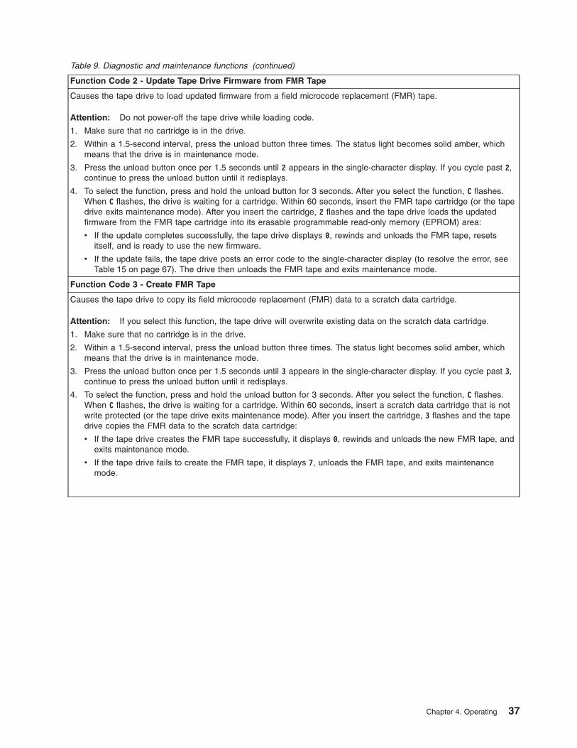
Table 9. Diagnostic and maintenance functions (continued)
Function Code 2 - Update Tape Drive Firmware from FMR Tape
Causes the tape drive to load updated firmware from a field microcode replacement (FMR) tape.
Attention: Do not power-off the tape drive while loading code.
1. Make sure that no cartridge is in the drive.
2. Within a 1.5-second interval, press the unload button three times. The status light becomes solid amber, whichmeans that the drive is in maintenance mode.
3. Press the unload button once per 1.5 seconds until 2 appears in the single-character display. If you cycle past 2,continue to press the unload button until it redisplays.
4. To select the function, press and hold the unload button for 3 seconds. After you select the function, C flashes.When C flashes, the drive is waiting for a cartridge. Within 60 seconds, insert the FMR tape cartridge (or the tapedrive exits maintenance mode). After you insert the cartridge, 2 flashes and the tape drive loads the updatedfirmware from the FMR tape cartridge into its erasable programmable read-only memory (EPROM) area:
v If the update completes successfully, the tape drive displays 0, rewinds and unloads the FMR tape, resetsitself, and is ready to use the new firmware.
v If the update fails, the tape drive posts an error code to the single-character display (to resolve the error, seeTable 15 on page 67). The drive then unloads the FMR tape and exits maintenance mode.
Function Code 3 - Create FMR Tape
Causes the tape drive to copy its field microcode replacement (FMR) data to a scratch data cartridge.
Attention: If you select this function, the tape drive will overwrite existing data on the scratch data cartridge.
1. Make sure that no cartridge is in the drive.
2. Within a 1.5-second interval, press the unload button three times. The status light becomes solid amber, whichmeans that the drive is in maintenance mode.
3. Press the unload button once per 1.5 seconds until 3 appears in the single-character display. If you cycle past 3,continue to press the unload button until it redisplays.
4. To select the function, press and hold the unload button for 3 seconds. After you select the function, C flashes.When C flashes, the drive is waiting for a cartridge. Within 60 seconds, insert a scratch data cartridge that is notwrite protected (or the tape drive exits maintenance mode). After you insert the cartridge, 3 flashes and the tapedrive copies the FMR data to the scratch data cartridge:
v If the tape drive creates the FMR tape successfully, it displays 0, rewinds and unloads the new FMR tape, andexits maintenance mode.
v If the tape drive fails to create the FMR tape, it displays 7, unloads the FMR tape, and exits maintenancemode.
Chapter 4. Operating 37

Table 9. Diagnostic and maintenance functions (continued)
Function Code 4 - Force a Drive Dump
Causes the tape drive to perform a collection (or dump) of data. (A drive dump is also known as a save of thefirmware trace.) The dump (firmware trace) can only be analyzed by IBM.Note: When an error code displays, a red dot also displays to remind you that a dump already exists. If you performFunction Code 4, it will overwrite the dump and cause the error information to be lost.
1. Make sure that no cartridge is in the drive.
2. Within a 1.5-second interval, press the unload button three times. The status light becomes solid amber, whichmeans that the drive is in maintenance mode.
3. Press the unload button once per 1.5 seconds until 4 appears in the single-character display. If you cycle past 4,continue to press the unload button until it redisplays.
4. To select the function, press and hold the unload button for 3 seconds. After you select the function, 4 displays,followed by 0. The single-character display then goes blank, and the tape drive exits maintenance mode.
An illuminated red dot on the single-character display indicates that a drive dump has been created. To retrieve thedump from the drive, see Function Code 5 on page 38.
You can also perform this operation when the tape drive is in normal operating mode. Simply press and hold theunload button for 10 seconds.
Function Code 5 - Copy the Drive Dump to Tape (at Beginning of Tape)
Causes the tape drive to copy data from a drive dump (captured with Function Code 4) to the beginning of a scratchdata cartridge. An illuminated red dot on the single-character display indicates that a drive dump has been created.
1. Make sure that no cartridge is in the drive.
2. Within a 1.5-second interval, press the unload button three times. The status light becomes solid amber, whichmeans that the drive is in maintenance mode.
3. Press the unload button once per 1.5 seconds until 5 appears in the single-character display. If you cycle past 5,continue to press the unload button until it redisplays.
4. To select the function, press and hold the unload button for 3 seconds. After you select the function, C flashes.When C flashes, the drive is waiting for a cartridge. Within 60 seconds, insert a scratch data cartridge that is notwrite-protected (or the tape drive exits maintenance mode). After you insert the cartridge, 5 flashes and the tapedrive writes the dump data to the tape (at the beginning of the tape). When the function is complete, 0 displays,the drive rewinds and unloads the tape, and exits maintenance mode.
From the server, issue the SCSI READ command to read the dump from the tape to a file or electronic image.For information about where to send the electronic image, contact your OEM Product Application Engineer (PAE).
38 IBM TotalStorage LTO Ultrium 2 Tape Drive

Table 9. Diagnostic and maintenance functions (continued)
Function Code 6 - Run SCSI or Fibre Channel Wrap Test
Causes the drive to perform one of the following:
v A check of the SCSI circuitry from and to the SCSI connector
v A check of the Fibre Channel circuitry from and to the Fibre Channel connector or fiber cable
To run the test, determine whether your drive uses a SCSI or Fibre Channel interface, then choose one of thefollowing procedures.
Running a SCSI Wrap Test
This test evaluates the SCSI circuitry. A SCSI LVD wrap plug, a SCSI LVD terminator, and a Y-cable are required forthis procedure.Note: You can terminate the Generation 1 drive internally while running the SCSI wrap test. Internal termination isnot built into the Generation 2 drive, therefore you must run the SCSI wrap test by using a Y-cable and externaltermination.
Before you select this function, you must configure the drive to supply term power, terminate the SCSI bus, andattach the SCSI wrap plug. Configure the drive to supply term power by placing a jumper on pin 6 of the drive’s SCSIID connector (as shown by the shaded area in the figure below).
A67E
0049
Connect a Y-cable to the drive’s SCSI connector. Place a terminator on one end of the Y-cable and the wrap plug onthe other end.
1. Ensure that the drive does not contain a cartridge.
2. Within a 1.5-second interval, press the unload button three times. The status light becomes solid amber, whichmeans that the drive is in maintenance mode.
3. Press the unload button once per 1.5 seconds until 6 appears in the single-character display. If you cycle past 6,continue to press the unload button until it redisplays.
4. To select the function, press and hold the unload button for 3 seconds. After you select the function, the tapedrive automatically starts the test:
v If the test is successful, it loops and begins again. To halt the test, press the unload button. The driveacknowledges the request by slowing the length of time that the currently displayed character flashes on thesingle-character display (from twice per second to once per second). The test continues to the end of its loop,then stops. 0 displays and the drive exits maintenance mode. To continue to isolate the problem, go to “FixingSCSI Bus Errors” on page 77 and locate the steps to take after you run the SCSI wrap test.
v If the test fails, 8 displays, the test stops, and the tape drive exits maintenance mode. To resolve the error,replace the tape drive (see “Removing a SCSI Tape Drive from an Enclosure” on page 83).
Chapter 4. Operating 39

Table 9. Diagnostic and maintenance functions (continued)
Running a Fibre Channel Wrap Test
This test evaluates the Fibre Channel circuitry at the drive’s Fibre Channel connector, then at the fiber cable. A FibreChannel wrap plug is required for this procedure. To run the wrap test through the fiber cable, a duplex adapter isrequired.
All cables and wrap plugs are hot-pluggable (that is, they can be removed from or added to the drive while the driveor its enclosure is powered-on). Do not bend the fiber cable more than a radius of 50.8 mm (2 in.) or the optical fibermay break.
1. Take all devices on the Fibre Channel offline (for instructions, refer to your server’s documentation).
2. Make sure that no cartridge is in the drive.
3. Disconnect the fiber cable from the drive and replace it with the Fibre Channel wrap plug. (When you disconnectthe cable, the connection to the Fibre Channel loop may break, but will be restored at the end of the procedurewhen you reconnect the cable. For other devices on the loop, operations may temporarily be disrupted.)
Attention: Do not run the wrap test while the drive is connected to a Fibre Channel loop. This could disturbthe Fibre Channel loop and cause performance or I/O problems.
4. Within a 1.5-second interval, press the unload button three times. The status light becomes solid amber, whichmeans that the drive is in maintenance mode.Note: If a cartridge is in the drive, it will eject the first time that you press the unload button and the drive willnot be placed in maintenance mode. To continue placing the drive in maintenance mode, remove the cartridgeand repeat this step.
5. Press the unload button once per 1.5 seconds until 6 appears in the single-character display.Note: If you cycle past 6, press the unload button once per second until it redisplays.
Testing the Circuitry at the Drive’s Fibre Channel Connector
6. To select the function, press and hold the unload button for 3 seconds. After you select the function, the tapedrive automatically starts the test:
v If the test is successful, the circuitry at the drive’s Fibre Channel connector is working properly. The test loopsand begins again. Press the unload button. 0 displays and the tape drive exits maintenance mode. Continueto step 7 to test the fiber cable.
v If the test fails, an error code displays and the status light flashes amber. The test stops and the drive exitsmaintenance mode. To resolve the error, locate the code in Table 15 on page 67.
7. Disconnect the Fibre Channel wrap plug from the drive.Testing the Circuitry at the Fiber Cable
8. Connect the duplex adapter, then the Fibre Channel wrap plug to the end of the fiber cable.Note: The Fibre Channel wrap test can only be run on cable lengths up to 250 meters (820 ft).
9. Within a 1.5-second interval, press the unload button three times. The status light becomes solid amber, whichmeans that the drive is in maintenance mode.Note: If a cartridge is in the drive, it will eject the first time that you press the unload button and the drive willnot be placed in maintenance mode. To continue placing the drive in maintenance mode, remove the cartridgeand repeat this step.
10. Press the unload button once per 1.5 seconds until 6 appears in the single-character display.Note: If you cycle past 6, press the unload button once per second until it redisplays.
11. To select the function, press and hold the unload button for 3 seconds. After you select the function, the tapedrive automatically starts the test:
v If the test is successful, the drive and the cable are working properly. The problem is at the server. To resolvethe error, refer to the service guide for the server.
v If the test fails, replace the fiber cable.
12. Remove the Fibre Channel wrap plug and the duplex adapter, and reconnect the fiber cable.
40 IBM TotalStorage LTO Ultrium 2 Tape Drive

Table 9. Diagnostic and maintenance functions (continued)
Function Code 7 - Run LDI or RS-422 Wrap Test
Causes the tape drive to perform a check of the circuitry from and to the LDI or RS-422 connector.
Before you select this function, attach an LDI or RS-422 wrap plug to the tape drive’s LDI or RS-422 connector (inplace of the LDI or RS-422 cable).
1. Make sure that no cartridge is in the drive.
2. Within a 1.5-second interval, press the unload button three times. The status light becomes solid amber, whichmeans that the drive is in maintenance mode.
3. Press the unload button once per 1.5 seconds until 7 appears in the single-character display. If you cycle past 7,continue to press the unload button until it redisplays.
4. To select the function, press and hold the unload button for 3 seconds. After you select the function, 7 flashesand the tape drive automatically starts the test:
v If the test is successful, it loops and begins again. To halt the test, press the unload button. The test continuesto the end of its loop and then stops. The tape drive then displays 0 and exits maintenance mode.
v If the test fails, 9 displays, the test stops, and the tape drive exits maintenance mode. To resolve the error,locate 9 in Table 15 on page 67.
Function Code 8 - Convert FMR Tape to Scratch Tape
Causes the tape drive to erase the field microcode replacement (FMR) data on a scratch data cartridge and rewritethe cartridge memory on the tape. This turns the cartridge into a valid scratch data cartridge.
1. Make sure that no cartridge is in the drive.
2. Within a 1.5-second interval, press the unload button three times. The status light becomes solid amber, whichmeans that the drive is in maintenance mode.
3. Press the unload button once per 1.5 seconds until 8 appears in the single-character display. If you cycle past 8,continue to press the unload button until it redisplays.
4. To select the function, press and hold the unload button for 3 seconds. After you select the function, C flashes.When C flashes, the drive is waiting for a cartridge. Within 60 seconds, insert the FMR cartridge (or the tape driveexits maintenance mode). After you insert the cartridge, 8 flashes, the tape drive erases the firmware on the tape,then rewrites the header in the cartridge memory to change the cartridge to a valid scratch data cartridge:
v If the operation is successful, the tape drive displays 0, rewinds and ejects the newly converted scratch datacartridge, and exits maintenance mode.
v If the operation is not successful, an error code displays. To resolve the error, locate the code in Table 15 onpage 67.
Chapter 4. Operating 41

Table 9. Diagnostic and maintenance functions (continued)
Function Code 9 - Display Error Code Log
Causes the tape drive to display the last 10 error codes, one at a time (the codes are ordered; the most recent ispresented first and the oldest (tenth) is presented last).
1. Make sure that no cartridge is in the drive.
2. Within a 1.5-second interval, press the unload button three times. The status light becomes solid amber, whichmeans that the drive is in maintenance mode.
3. Press the unload button once per 1.5 seconds until 9 appears in the single-character display. If you cycle past 9,continue to press the unload button until it redisplays.
4. To select the function, press and hold the unload button for 3 seconds. After you select the function, press theunload button to view the most recent error code. Press the unload button again to view successive error codes.If you press the unload button for 3 seconds after the tenth error code displays, 0 displays (if there are no errorsin the log) and the drive exits maintenance mode.
Function Code A - Clear Error Code Log
Causes the tape drive to erase the contents of the error code log.
1. Make sure that no cartridge is in the drive.
2. Within a 1.5-second interval, press the unload button three times. The status light becomes solid amber, whichmeans that the drive is in maintenance mode.
3. Press the unload button once per 1.5 seconds until A appears in the single-character display. If you cycle past A,continue to press the unload button until it redisplays.
4. To select the function, press and hold the unload button for 3 seconds. After you select the function, the tapedrive erases all errors from the error code log, displays 0, then exits maintenance mode.
Function Code C - Insert Cartridge into Tape Drive
This function cannot be selected by itself. It relates to other maintenance functions (such as Run Tape DriveDiagnostics or Create FMR Tape) that require an FMR tape cartridge or scratch tape cartridge that is not writeprotected.
42 IBM TotalStorage LTO Ultrium 2 Tape Drive

Table 9. Diagnostic and maintenance functions (continued)
Function Code E - Test Cartridge & Media
Causes the tape drive to perform a Write/Read test (on the edge bands) to ensure that a suspect cartridge and itsmagnetic tape are acceptable. The tape drive takes approximately 10 minutes to run the test.
Attention: Data on the suspect tape will be overwritten.
1. Make sure that no cartridge is in the drive.
2. Within a 1.5-second interval, press the unload button three times. The status light becomes solid amber, whichmeans that the drive is in maintenance mode.
3. Press the unload button once per 1.5 seconds until E appears in the single-character display. If you cycle past E,continue to press the unload button until it redisplays.
4. To select the function, press and hold the unload button for 3 seconds. After you select the function, C flashes.When C flashes, the drive is waiting for a cartridge. Within 60 seconds, insert the suspect data cartridge (or thetape drive exits maintenance mode). After you insert the cartridge, E flashes and the test begins:
v If no error is detected, the test begins again and runs for a maximum of 10 times. After the tenth loop, the teststops and the drive automatically exits maintenance mode. To halt the test, press the unload button. The driveacknowledges the request by slowing the length of time that the currently displayed character flashes on thesingle-character display (from twice per second to once per second). The test continues to the end of its loopand then stops. The tape drive then rewinds and unloads the cartridge, displays 0, and exits maintenancemode.
v If an error is detected, the tape drive displays 7, unloads the tape cartridge, and exits maintenance mode. Toresolve the error, locate 7 in Table 15 on page 67.
Function Code F - Fast Read/Write Test
Causes the tape drive to perform tests to ensure that the drive can read from and write to tape. This diagnosticperforms fewer tests than the Run Tape Drive Diagnostics test (Function Code 1). The tape drive takes approximatelythree minutes to run the test. The Fast Read/Write Test is not as comprehensive a test and is not recommended forisolating errors between the drive and the media.
Attention: Data on the suspect tape will be overwritten.
1. Make sure that no cartridge is in the drive.
2. Within a 1.5-second interval, press the unload button three times. The status light becomes solid amber, whichmeans that the drive is in maintenance mode.
3. Press the unload button once per 1.5 seconds until F appears in the single-character display. If you cycle past F,continue to press the unload button until it redisplays.
4. To select the function, press and hold the unload button for 3 seconds. After you select the function, C flashes.When C flashes, the drive is waiting for a cartridge. Within 60 seconds, insert the suspect data cartridge (or thetape drive exits maintenance mode). After you insert the cartridge, F flashes and the test begins.
v If no error is detected, the test begins again and runs for a maximum of 10 times. Each loop takesapproximately 3 minutes to run. After the tenth loop, the test stops and the drive automatically exitsmaintenance mode. To halt the test, press the unload button. The drive acknowledges the request by slowingthe length of time that the currently displayed character flashes on the single-character display (from twice persecond to once per second). The test continues to the end of its loop and then stops. The tape drive thenrewinds and unloads the cartridge, displays 0, and exits maintenance mode.
v If an error is detected, the tape drive displays an error code, unloads the tape cartridge, and exits maintenancemode. To resolve the error, locate the code in Table 15 on page 67.
Chapter 4. Operating 43

Table 9. Diagnostic and maintenance functions (continued)
Function Code H - Test Head
Causes the tape drive to perform the Head Resistance Measurements test and a Write/Read test (on the center ofthe tape). The drive runs these tests to ensure that the tape drive’s head and tape-carriage mechanics are workingcorrectly. The tape drive takes approximately 10 minutes to run the test.
1. Make sure that no cartridge is in the drive.
2. Within a 1.5-second interval, press the unload button three times. The status light becomes solid amber, whichmeans that the drive is in maintenance mode.
3. Press the unload button once per 1.5 seconds until H appears in the single-character display. If you cycle past H,continue to press the unload button until it redisplays.
4. To select the function, press and hold the unload button for 3 seconds. After you select the function, C flashes.When C flashes, the drive is waiting for a cartridge. Within 60 seconds, insert a scratch data cartridge (or the tapedrive exits maintenance mode). After you insert the cartridge, H flashes and the test begins:
v If no error is detected, the test begins again and runs for a maximum of 10 times. Each loop takesapproximately 10 minutes to run. After the tenth loop, the test stops and the drive automatically exitsmaintenance mode. To halt the test, press the unload button. The drive acknowledges the request by slowingthe length of time that the currently displayed character flashes on the single-character display (from twice persecond to once per second). The test continues to the end of its loop and then stops. The tape drive thenrewinds and unloads the cartridge, displays 0, and exits maintenance mode.
v If an error is detected, the tape drive displays 5, unloads the tape cartridge, and exits maintenance mode. Toresolve the error, locate 5 in Table 15 on page 67.
Function Code L - Reserved for Future Use
Reserved for future use.
Function Code P or U - Enable or Disable Post Error Reporting
Used by support personnel during error detection, this function is an alternate method of setting or preventing thepost error (PER) bit in the SCSI Read-Write Error Recovery Page. For more information, refer to the MODE SENSEcommand in the IBM TotalStorage LTO Ultrium Tape Drive SCSI Reference.
1. Make sure that no cartridge is in the drive.
2. Within a 1.5-second interval, press the unload button three times. The status light becomes solid amber, whichmeans that the drive is in maintenance mode.
3. Perform one of the following:
v To enable post error reporting, press the unload button once per 1.5 seconds until U appears in thesingle-character display. If you cycle past U, continue to press the unload button until it redisplays.
v To disable post error reporting, press the unload button once per 1.5 seconds until P appears in thesingle-character display. If you cycle past P, continue to press the unload button until it redisplays.
4. To select the function, press and hold the unload button for 3 seconds. After you select the function, the drivedisplays one of the following:
v P to indicate that post error reporting is enabled.
v U to indicate that post error reporting is disabled.
44 IBM TotalStorage LTO Ultrium 2 Tape Drive

Exiting Maintenance ModeTo manually exit maintenance mode, press the unload button once per second until0 appears on the single-character display. Press and hold the unload button for 3seconds. The drive exits maintenance mode (the solid amber status light becomessolid green, then turns off).
You can also exit maintenance mode by pressing the unload button during anymaintenance or diagnostic function.
Updating the FirmwareAttention: When updating firmware, do not power-off the tape drive until theupdate is complete, or the firmware may be lost.
Periodically check for updated levels of drive firmware by visiting the web athttp://www.ibm.com/storage/lto. You can update your drive’s firmware by:
v Obtaining the new firmware image and downloading it to the drive through theSCSI or Fibre Channel interface
v Obtaining the new firmware image and downloading it to the drive through theLDI or RS-422 interface
v Loading the firmware from a field microcode replacement (FMR) tape cartridge
For instructions about how to obtain a new firmware image or FMR tape, visit thepreceding web site. To update the firmware, refer to the following sections.
Updating Firmware through the SCSI or Fibre Channel Interface
Attention: SCSI drives and Fibre Channel drives require different firmwareimages.
When you update the tape drive’s firmware by using the SCSI or Fibre Channelinterface, the procedure varies, depending on whether your server uses an IBMtape device driver or a non-IBM tape device driver (such as a driver from Sun,Hewlett-Packard, or Microsoft).
For instructions about updating firmware from a server that uses an IBM tapedevice driver, refer to the IBM Ultrium Device Drivers Installation and User’s Guide.
To update firmware from a server that uses a non-IBM tape device driver, refer tothe documentation for that device driver.
Updating Firmware through the Library/Drive InterfaceThe Ultrium 2 Tape Drive includes a firmware update feature that allows a tapelibrary to download firmware to the drive by using the Library/Drive Interface (LDI)while the drive performs normal host operations on logical unit number (LUN) 0 ofthe SCSI Protocol Interface. The update typically takes 63 seconds and a maximumof 140 seconds. To activate the new firmware, cycle power to the drive, or unloadthe drive and issue a Power-on Reset command. The command may be receivedby the SCSI interface or the LDI (RS-422) interface.
Note: If a Power-on Reset command is received while a cartridge is loaded in thedrive, the drive will respond with a Check Condition. It will not activate thenew code level until you cycle power, or until you receive a Power-on Resetcommand when the drive does not contain a cartridge.
Chapter 4. Operating 45
Updating the Firmware with an FMR Tape Cartridge
Attention: SCSI drives and Fibre Channel drives require different firmwareimages.
To update the Ultrium 2 Tape Drive’s firmware from an FMR tape cartridge:
1. Ensure that the tape drive is unloaded.
2. Place the drive in maintenance mode by pressing the unload button three timeswithin a 1.5-second interval. The status light becomes solid amber, whichmeans that the drive is in maintenance mode.
3. Press the unload button once per 1.5 seconds until 2 displays, then press andhold the button for 3 seconds. When C flashes, the drive is waiting for acartridge.
4. Insert the FMR tape cartridge. 2 flashes, the drive loads the updated firmwarefrom the cartridge, and the status light flashes amber. When the updatecompletes successfully, 0 displays and the cartridge automatically ejects.
The drive resets itself and automatically activates the new firmware.
If the update fails, an error code displays. To resolve the error, locate the code inTable 15 on page 67.
46 IBM TotalStorage LTO Ultrium 2 Tape Drive

Chapter 5. Using the Media
The IBM TotalStorage LTO Ultrium 2 Tape Drive uses the following cartridge types:
v IBM TotalStorage LTO Ultrium 200 GB Data Cartridge (Generation 2)
v IBM LTO Ultrium Cleaning Cartridge
v IBM TotalStorage Cleaning Cartridge (Ultrium LTO 2)
The Ultrium 2 Tape Drive (Generation 2) is compatible with the cartridges of itspredecessor, the IBM Ultrium Internal Tape Drive (Generation 1). Cartridgecompatibility for the Ultrium 2 Tape Drive is as follows:
v Reads and writes Generation 2 cartridges to Generation 2 format
v Reads and writes Generation 1 cartridges to Generation 1 format
v Does not write Generation 2 cartridges to Generation 1 format
v Does not write Generation 1 cartridges to Generation 2 format
Figure 11 shows the IBM TotalStorage LTO Ultrium 200 GB Data Cartridge and itscomponents.
�1� LTO cartridge memory �4� Write-protect switch�2� Cartridge door �5� Label area�3� Leader pin �6� Insertion guide
Figure 11. The IBM TotalStorage LTO Ultrium 200 GB Data Cartridge
© Copyright IBM Corp. 2002 47
In addition to using LTO Ultrium 2 Tape Cartridges with up to 200 GB capacity, thetape drive reads and writes to certified LTO Ultrium Tape Cartridges that havecapacities of 100, 50, 30, and 10 GB. If you want to control the capacity of thecartridge (for example, if you want to limit the capacity to obtain a faster seek time)you can do so by issuing the SCSI command SET CAPACITY. For informationabout this command, refer to the IBM TotalStorage LTO Ultrium Tape Drive SCSIReference.
To ensure that your tape drive conforms to IBM’s specifications for reliability, useonly IBM TotalStorage LTO Ultrium Tape Cartridges. You may use otherLTO-certified data cartridges, but they may not meet the standards of reliability thatare established by IBM. The IBM TotalStorage LTO Ultrium 200 GB Data Cartridgecannot be interchanged with the media used in other IBM non-LTO Ultrium tapeproducts.
Data CartridgeThe IBM TotalStorage LTO Ultrium 200 GB Data Cartridge contains 1/2-inch,dual-coat, metal-particle tape that has a native data capacity of 200 GB (400 GB at2:1 compression). When processing the tape, the IBM TotalStorage LTO Ultrium 2Tape Drive uses a linear, serpentine recording format, and reads and writes data on512 tracks, eight tracks at a time. The first set of eight tracks is written from nearthe beginning of the tape to near the end of the tape. The head then repositions tothe next set of eight tracks for the return pass. This process continues until alltracks are written and the tape is full, or until all data is written.
The IBM TotalStorage LTO Ultrium 200 GB Data Cartridge includes a LinearTape-Open Cartridge Memory (LTO-CM) chip (�1� in Figure 11 on page 47), thatcontains information about the cartridge and the tape (such as the name of themanufacturer that created the tape), as well as statistical information about thecartridge’s use. Whenever you unload a tape cartridge, the tape drive writes anypertinent information to the cartridge memory. The storage capacity of the LTO-CMis 4096 bytes.
The cartridge door �2� protects the tape from contamination when the cartridge isout of the drive. Behind the door, the tape is attached to a leader pin �3�. Whenyou insert the cartridge into the drive, a threading mechanism pulls the pin (andtape) out of the cartridge, across the drive head, and onto a non-removable takeupreel. The head can then read or write data from or to the tape.
The write-protect switch �4� prevents data from being written to the tape cartridge.The label area �5� provides a location for you to place a label. Affix only a bar codelabel. When affixing a label, place it only in the recessed label area. A label thatextends outside of the recessed area can cause loading problems in the drive. Theinsertion guide �6� is a large, notched area that prevents you from inserting thecartridge incorrectly.
You can order tape cartridges with the bar code labels included, or you can ordercustom labels. To obtain tape cartridges and bar code labels, see “Ordering MediaSupplies” on page 63.
The IBM TotalStorage LTO Ultrium 200 GB Data Cartridge has a nominal cartridgelife of 5000 load and unload cycles. The Generation 2 cartridge is purple; theGeneration 1 cartridge is black.
48 IBM TotalStorage LTO Ultrium 2 Tape Drive

Cleaning CartridgesThe Ultrium 2 Tape Drive is compatible with the IBM LTO Ultrium CleaningCartridge (part number 08L9124) and the IBM TotalStorage Cleaning Cartridge(Ultrium LTO 2) (part number 35L2086).
The IBM TotalStorage Cleaning Cartridge functions with Ultrium-format tape drivesthat are produced by compliance-verified manufacturers. The cartridge lets you buyand use a single cleaning cartridge for all of your tape drives, rather than spendtime and money to support several different cleaning cartridges.
The IBM TotalStorage Cleaning Cartridge (Ultrium LTO 2) is downward-compatiblewith the Ultrium Internal Tape Drive (Generation 1). To enable your Generation 1drive to use the cartridge, simply download and install the latest drive firmware (forinstructions, see “Updating the Firmware” on page 45).
The drive itself determines when a head needs to be cleaned. It alerts you bydisplaying C on the single-character display and causing the status light to becomeflashing amber. To clean the head, insert the cleaning cartridge into the tape loadcompartment (see Figure 10 on page 34). The tape drive performs the cleaningautomatically. When the cleaning is finished, the drive ejects the cartridge.
To remove a cleaning cartridge, see “Unload Button” on page 33. The IBMTotalStorage Cleaning Cartridge (Ultrium LTO 2) and the IBM LTO Ultrium CleaningCartridge are valid for 50 uses (the cartridge’s LTO-CM chip tracks the number oftimes that the cartridge is used).
Chapter 5. Using the Media 49

Setting the Write-Protect SwitchThe position of the write-protect switch on the tape cartridge (see �1� in Figure 12)determines whether you can write to the tape:
v If the switch is set to (solid red), data cannot be written to the tape.
v If the switch is set to unlocked (black void), data can be written to the tape.
To set the switch, slide it left or right to the desired position.
Handling the Cartridges
Attention: Do not insert a damaged tape cartridge into yourUltrium 2 Tape Drive. A damaged cartridge can interfere with thereliability of the drive and may void the warranties of the drive andthe cartridge. Before inserting a tape cartridge, inspect thecartridge case, cartridge door, and write-protect switch for breaks.If you need to recover data from a damaged cartridge, contactyour OEM Product Application Engineer (PAE).
Incorrect handling or an incorrect environment can damage the LTO Ultrium TapeCartridge or its magnetic tape. To avoid damage to your tape cartridges and toensure the continued high reliability of your IBM TotalStorage LTO Ultrium 2 TapeDrive, use the following guidelines.
A67E
0026
1
Figure 12. Setting the write-protect switch
50 IBM TotalStorage LTO Ultrium 2 Tape Drive

Provide Trainingv Post procedures that describe proper media handling in places where people
gather.
v Ensure that anyone who handles tape has been properly trained in handling andshipping procedures. This includes operators, users, programmers, archivalservices, and shipping personnel.
v Ensure that any service or contract personnel who perform archiving are properlytrained in media-handling procedures.
v Include media-handling procedures as part of any services contract.
v Define and make personnel aware of data recovery procedures.
Ensure Proper Packagingv When you ship a cartridge, ship it in its original or better packaging.
v Always ship or store a cartridge in a jewel case.
v Use only a recommended shipping container that securely holds the cartridge inits jewel case during transportation. Ultrium Turtlecases (by Perm-A-Store) havebeen tested and found to be satisfactory (see Figure 13). They are available atwww.turtlecase.com.
v Never ship a cartridge in a commercial shipping envelope. Always place it in abox or package.
v If you ship the cartridge in a cardboard box or a box of a sturdy material, ensurethe following:
– Place the cartridge in polyethylene plastic wrap or bags to protect it from dust,moisture, and other contaminants.
– Pack the cartridge snugly; do not allow it to move around.
– Double-box the cartridge (place it inside a box, then place that box inside theshipping box) and add padding between the two boxes (see Figure 14 onpage 52).
Figure 13. Tape cartridges in a Turtlecase
Chapter 5. Using the Media 51
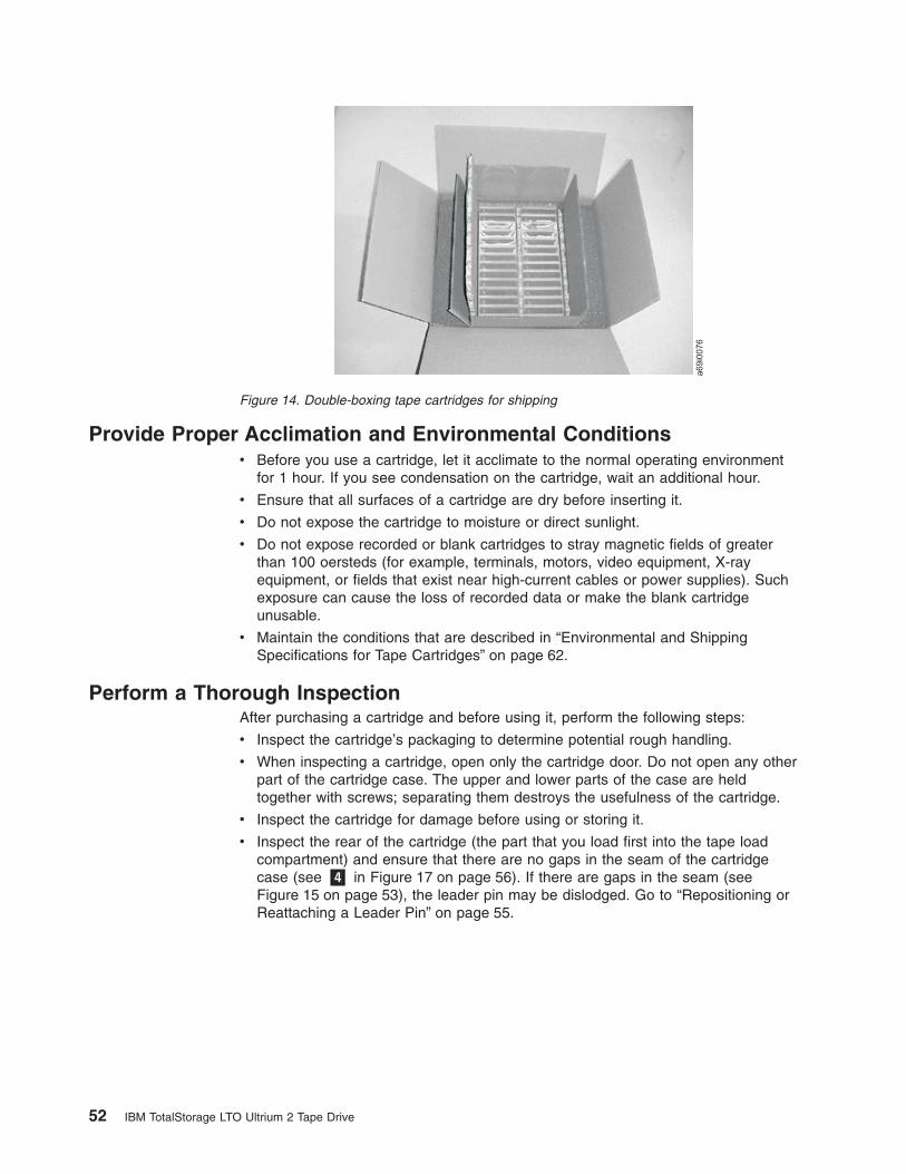
Provide Proper Acclimation and Environmental Conditionsv Before you use a cartridge, let it acclimate to the normal operating environment
for 1 hour. If you see condensation on the cartridge, wait an additional hour.
v Ensure that all surfaces of a cartridge are dry before inserting it.
v Do not expose the cartridge to moisture or direct sunlight.
v Do not expose recorded or blank cartridges to stray magnetic fields of greaterthan 100 oersteds (for example, terminals, motors, video equipment, X-rayequipment, or fields that exist near high-current cables or power supplies). Suchexposure can cause the loss of recorded data or make the blank cartridgeunusable.
v Maintain the conditions that are described in “Environmental and ShippingSpecifications for Tape Cartridges” on page 62.
Perform a Thorough InspectionAfter purchasing a cartridge and before using it, perform the following steps:
v Inspect the cartridge’s packaging to determine potential rough handling.
v When inspecting a cartridge, open only the cartridge door. Do not open any otherpart of the cartridge case. The upper and lower parts of the case are heldtogether with screws; separating them destroys the usefulness of the cartridge.
v Inspect the cartridge for damage before using or storing it.
v Inspect the rear of the cartridge (the part that you load first into the tape loadcompartment) and ensure that there are no gaps in the seam of the cartridgecase (see �4� in Figure 17 on page 56). If there are gaps in the seam (seeFigure 15 on page 53), the leader pin may be dislodged. Go to “Repositioning orReattaching a Leader Pin” on page 55.
Figure 14. Double-boxing tape cartridges for shipping
52 IBM TotalStorage LTO Ultrium 2 Tape Drive
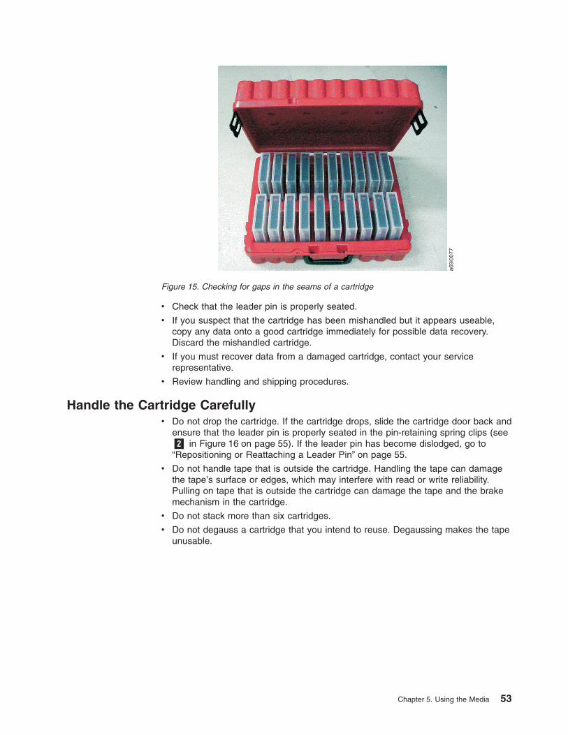
v Check that the leader pin is properly seated.
v If you suspect that the cartridge has been mishandled but it appears useable,copy any data onto a good cartridge immediately for possible data recovery.Discard the mishandled cartridge.
v If you must recover data from a damaged cartridge, contact your servicerepresentative.
v Review handling and shipping procedures.
Handle the Cartridge Carefullyv Do not drop the cartridge. If the cartridge drops, slide the cartridge door back and
ensure that the leader pin is properly seated in the pin-retaining spring clips (see�2� in Figure 16 on page 55). If the leader pin has become dislodged, go to“Repositioning or Reattaching a Leader Pin” on page 55.
v Do not handle tape that is outside the cartridge. Handling the tape can damagethe tape’s surface or edges, which may interfere with read or write reliability.Pulling on tape that is outside the cartridge can damage the tape and the brakemechanism in the cartridge.
v Do not stack more than six cartridges.
v Do not degauss a cartridge that you intend to reuse. Degaussing makes the tapeunusable.
Figure 15. Checking for gaps in the seams of a cartridge
Chapter 5. Using the Media 53
Examples of Cartridge ProblemsExample: Improper Placement of Leader Pin
The leader pin is misaligned. Perform the following steps:
1. Look for cartridge damage.
2. Use the IBM Leader Pin Reattachment Kit (part number 08L9129) to correctlyseat the pin (see “Repositioning a Leader Pin” on page 55). Then, immediatelyuse data recovery procedures to minimize chances of data loss.
Example: Split Cartridge Case
The cartridge’s case is damaged. There is a high possibility of media damage andpotential loss. Perform the following steps:
1. Look for cartridge mishandling.
2. Use the IBM Leader Pin Reattachment Kit (part number 08L9129) to correctlyseat the pin (see “Repositioning a Leader Pin” on page 55). Then, immediatelyuse data recovery procedures to minimize chances of data loss.
3. Review media-handling procedures.
54 IBM TotalStorage LTO Ultrium 2 Tape Drive

Repositioning or Reattaching a Leader Pin
Attention: Use a repaired tape cartridge only to recover dataand move it to another cartridge. Continued use of a repairedcartridge may void the warranties of the drive and the cartridge.
If the leader pin in your cartridge becomes dislodged from its pin-retaining springclips or detaches from the tape, you must use the IBM Leader Pin Reattachment Kit(part number 08L9129) to reposition or reattach it. (Do not reattach the pin if youmust remove more than 7 meters (23 feet) of leader tape.) The sections that followdescribe each procedure.
Repositioning a Leader PinA leader pin that is improperly seated inside a cartridge can interfere with theoperation of the drive. Figure 16 shows a leader pin in the incorrect �1� and correct�2� positions.
To place the leader pin in its proper position, you will need the following tools:
v Plastic or blunt-end tweezers
v Cartridge manual rewind tool (from Leader Pin Reattachment Kit, part number08L9129)
Figure 16. Leader pin in the incorrect and correct positions. The cartridge door is open andthe leader pin is visible inside the cartridge.
Chapter 5. Using the Media 55
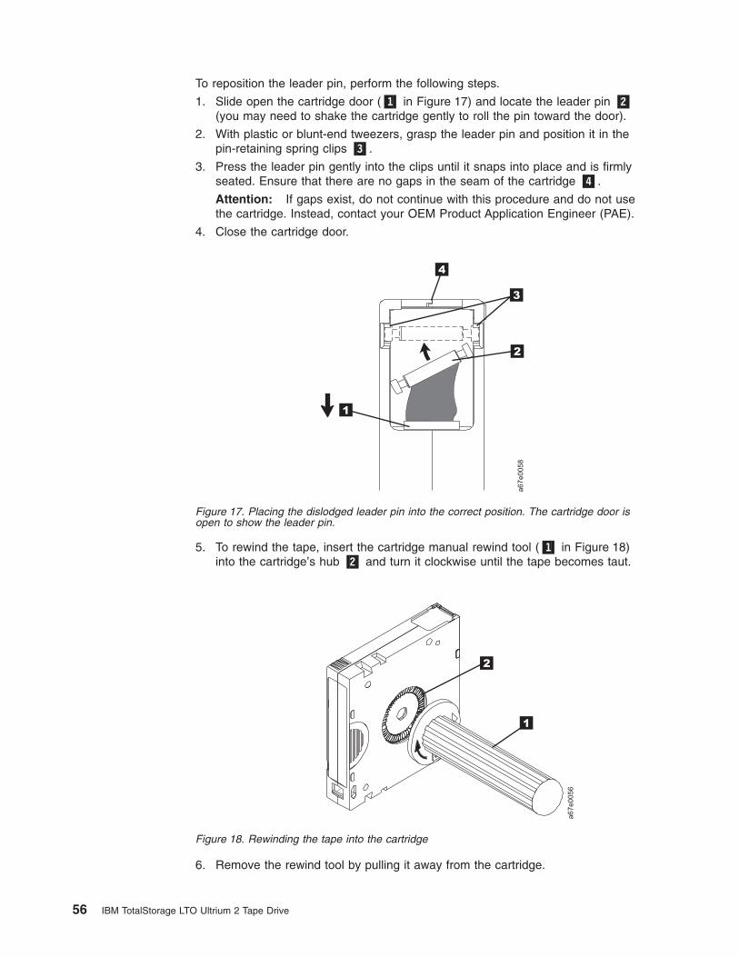
To reposition the leader pin, perform the following steps.
1. Slide open the cartridge door (�1� in Figure 17) and locate the leader pin �2�(you may need to shake the cartridge gently to roll the pin toward the door).
2. With plastic or blunt-end tweezers, grasp the leader pin and position it in thepin-retaining spring clips �3�.
3. Press the leader pin gently into the clips until it snaps into place and is firmlyseated. Ensure that there are no gaps in the seam of the cartridge �4�.
Attention: If gaps exist, do not continue with this procedure and do not usethe cartridge. Instead, contact your OEM Product Application Engineer (PAE).
4. Close the cartridge door.
5. To rewind the tape, insert the cartridge manual rewind tool (�1� in Figure 18)into the cartridge’s hub �2� and turn it clockwise until the tape becomes taut.
6. Remove the rewind tool by pulling it away from the cartridge.
Figure 17. Placing the dislodged leader pin into the correct position. The cartridge door isopen to show the leader pin.
Figure 18. Rewinding the tape into the cartridge
56 IBM TotalStorage LTO Ultrium 2 Tape Drive

Reattaching a Leader PinThe first meter of tape in a cartridge is leader tape. Once the leader tape has beenremoved there is a possibility of tape breakage. After reattaching the leader pin,transfer data from the defective tape cartridge. Do not reuse the defective tapecartridge.
The Leader Pin Reattachment Kit contains three parts:
v Leader pin attach tool (see �1� in Figure 19). A plastic brace that holds thecartridge door open.
v Cartridge manual rewind tool (see �2� in Figure 19). A device that fits into thecartridge’s hub and lets you wind the tape into and out of the cartridge.
v Pin supplies (see �3� in Figure 19). Leader pins and C-clips.
Attention:
v Use only the IBM Leader Pin Reattachment Kit to reattach the leader pin to thetape. Other methods of reattaching the pin will damage the tape, the drive, orboth.
v Use this procedure on your tape cartridge only when the leader pin detachesfrom the magnetic tape and you must copy the cartridge’s data onto anothercartridge. Destroy the damaged cartridge after you copy the data. This proceduremay affect the performance of the leader pin during threading and unloadingoperations.
v Touch only the end of the tape. Touching the tape in an area other than the endcan damage the tape’s surface or edges, which may interfere with read or writereliability.
A67E
00
42
1
2
3
Figure 19. Leader Pin Reattachment Kit
Chapter 5. Using the Media 57
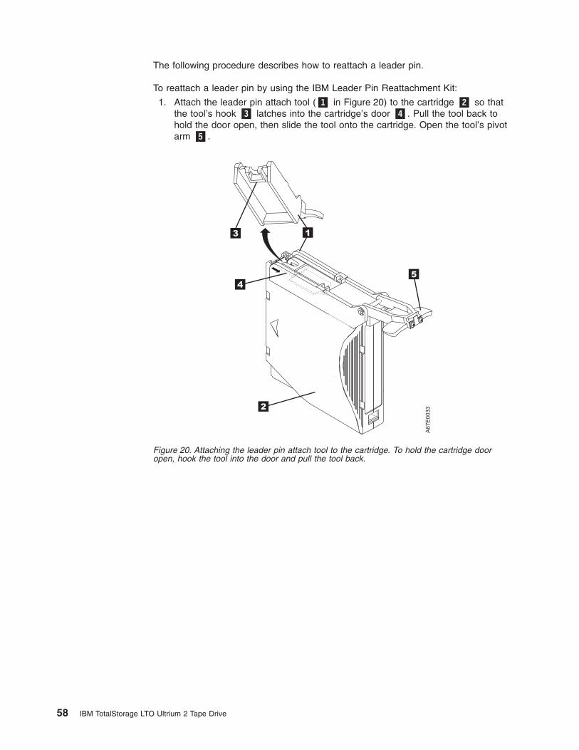
The following procedure describes how to reattach a leader pin.
To reattach a leader pin by using the IBM Leader Pin Reattachment Kit:
1. Attach the leader pin attach tool (�1� in Figure 20) to the cartridge �2� so thatthe tool’s hook �3� latches into the cartridge’s door �4�. Pull the tool back tohold the door open, then slide the tool onto the cartridge. Open the tool’s pivotarm �5�.
Figure 20. Attaching the leader pin attach tool to the cartridge. To hold the cartridge dooropen, hook the tool into the door and pull the tool back.
58 IBM TotalStorage LTO Ultrium 2 Tape Drive

2. To find the end of the tape inside the cartridge, attach the cartridge manualrewind tool (�1� in Figure 21) to the cartridge’s hub �2� by fitting the tool’steeth between the teeth of the hub. Turn the tool clockwise until you see theend of the tape inside the cartridge. Then, slowly turn the rewind toolcounterclockwise to bring the tape edge toward the cartridge door �3�.
3. Continue to turn the rewind tool counterclockwise until approximately 12.7 cm(5 in.) of tape hangs from the cartridge door. If necessary, grasp the tape andpull gently to unwind it from the cartridge.
4. Remove the rewind tool by pulling it away from the cartridge. Set the tool andthe cartridge aside.
5. On the leader pin (�1� in Figure 22), locate the open side of the C-clip �2�.The C-clip is a small black part that secures the tape �3� to the pin.
6. Remove the C-clip from the leader pin by using your fingers to push the clipaway from the pin. Set the pin aside and discard the clip.
Figure 21. Winding the tape out of the cartridge. Turn the cartridge manual rewind toolclockwise to see the end of the tape, then turn it counterclockwise to bring the tape to thecartridge door.
A67E
0036
1
2
3
Figure 22. Removing the C-clip from the leader pin. Use your fingers to push the C-clip fromthe leader pin.
Chapter 5. Using the Media 59
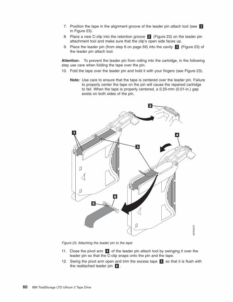
7. Position the tape in the alignment groove of the leader pin attach tool (see �1�in Figure 23).
8. Place a new C-clip into the retention groove �2� (Figure 23) on the leader pinattachment tool and make sure that the clip’s open side faces up.
9. Place the leader pin (from step 6 on page 59) into the cavity �3� (Figure 23) ofthe leader pin attach tool.
Attention: To prevent the leader pin from rolling into the cartridge, in the followingstep use care when folding the tape over the pin.
10. Fold the tape over the leader pin and hold it with your fingers (see Figure 23).
Note: Use care to ensure that the tape is centered over the leader pin. Failureto properly center the tape on the pin will cause the repaired cartridgeto fail. When the tape is properly centered, a 0.25-mm (0.01-in.) gapexists on both sides of the pin.
11. Close the pivot arm �4� of the leader pin attach tool by swinging it over theleader pin so that the C-clip snaps onto the pin and the tape.
12. Swing the pivot arm open and trim the excess tape �5� so that it is flush withthe reattached leader pin �6�.
A67E
0037
1
6
2
3
4
5
Figure 23. Attaching the leader pin to the tape
60 IBM TotalStorage LTO Ultrium 2 Tape Drive

13. Use your fingers to remove the leader pin from the cavity �3� in the leader pinattach tool.
14. Use the cartridge manual rewind tool to wind the tape back into the cartridge(wind the tape clockwise). Ensure that the leader pin is latched by thepin-retaining spring clips on each end of the leader pin.
15. Remove the rewind tool.
16. Remove the leader pin attach tool by lifting its end up and away from thecartridge.
Attention: Use a repaired tape cartridge only to recover dataand move it to another cartridge. Continued use of a repairedcartridge may void the warranties of the drive and the cartridge.
Chapter 5. Using the Media 61

Environmental and Shipping Specifications for Tape CartridgesBefore you use a tape cartridge, acclimate it to the operating environment for 24hours or the time necessary to prevent condensation in the drive (the time will vary,depending on the environmental extremes to which the drive was exposed).
The best storage container for the cartridges (until they are opened) is the originalshipping container. The plastic wrapping prevents dirt from accumulating on thecartridges and partially protects them from humidity changes.
When you ship a cartridge, place it in its jewel case or in a sealed, moisture-proofbag to protect it from moisture, contaminants, and physical damage. Ship thecartridge in a shipping container that has enough packing material to cushion thecartridge and prevent it from moving within the container.
Table 10 gives the environment for operating, storing, and shipping LTO UltriumTape Cartridges.
Table 10. Environment for operating, storing, and shipping the LTO Ultrium Tape Cartridge
Environmental Specifications
EnvironmentalFactor
OperatingOperational
Storage1 Archival Storage2 Shipping
Temperature10 to 45°C
(50 to 113°F)
16 to 32°C
(61 to 90°F)
16 to 25°C
(61 to 77°F)
−23 to 49°C
(−9 to 120°F)
Relative humidity(noncondensing)
10 to 80% 20 to 80% 20 to 50% 5 to 80%
Wet bulb temperature26°C
(79°F)
26°C
(79°F)
26°C
(79°F)
26°C
(79°F)
Notes:
1. Operational storage equals less than 1 year.
2. Archival storage equals 1 to 10 years.
62 IBM TotalStorage LTO Ultrium 2 Tape Drive

Disposing of Tape CartridgesUnder the current rules of the U.S. Environmental Protection Agency (EPA),regulation 40CFR261, the LTO Ultrium Tape Cartridge is classified asnon-hazardous waste. As such, it may be disposed of in the same way as normaloffice trash. These regulations are amended from time to time, and you shouldreview them at the time of disposal.
If your local, state, country (non-U.S.A.), or regional regulations are more restrictivethan EPA 40CFR261, you must review them before you dispose of a cartridge.Contact your account representative for information about the materials that are inthe cartridge.
If a tape cartridge must be disposed of in a secure manner, you can erase the dataon the cartridge by using a high-energy AC degausser (use a minimum of 1200oersted peak field over the entire space that the cartridge occupies). Degaussingmakes the cartridge unusable.
If you burn the cartridge and tape, ensure that the incineration complies with allapplicable regulations.
Ordering Media SuppliesTable 11 lists the cartridges and media supplies that you can order for the IBMTotalStorage LTO Ultrium 2 Tape Drive. To order media supplies, visit the web athttp://www.ibm.com/storage/lto.
Table 11. Media supplies for the IBM TotalStorage LTO Ultrium 2 Tape Drive
IBM Part Number Product Description
08L9870IBM TotalStorage LTO Ultrium 200 GB Data Cartridge (includes onlyhuman-writable labels)
19P5897IBM TotalStorage LTO Ultrium 200 GB Data Cartridge Bar CodeLabels, sheet of 20, black and white
08L9124IBM LTO Ultrium Cleaning Cartridge (includes only human-writablelabels)
35L2086 IBM TotalStorage Cleaning Cartridge (Ultrium LTO 2)
08L9267IBM LTO Ultrium Cleaning Cartridge Bar Code Labels, sheet of 20,black and white
Chapter 5. Using the Media 63

Ordering Custom Bar Code LabelsIf custom bar code labels are required for your data or cleaning cartridges, orderthem directly from the authorized label suppliers in Table 12.
Table 12. Authorized suppliers of custom bar code labels
In America In Europe and Asia
EDP/Colorflex697 South Pierce StreetLouisville, CO 80027U. S. A.Telephone: 800-522-3528http://www.colorflex.com/Ai/Home.asp
EDP Europe, Ltd.43 Redhills RoadSouth Woodham FerrersChelmsford, Essex CM3 5ULU. K.Telephone: 44 (0) 1245-322380http://www.edpeurope.com/media_labelling.htm
Dataware (LTO 2 only)7570 RenwickHouston, TX 77081U. S. A.Telephone: 800-426-4844http://www.datawarelabels.com/
Dataware Labels EuropeHeubergstrasse 9D-83052 Bruckmuhl-GottingGermanyTelephone: 49 806-29455http://www.datawarelabels.com/
NetCP. O. Box 320784Fairfield, CT 06432U. S. A.Telephone: 203-372-6382http://www.netcllc.com/
NetC Europe LtdTown Farm BungalowNorth CurryTauntonSomerset U. K. TA3 6LXTelephone: 44 (0) 1823 491439http://www.netclabels.co.uk
NetC Asia Pacific Pty LtdLocked Bag 14KenthurstNSW Australia 2156Telephone: 61 (0) 2 9654 8272http://www.netclabels.com.au
64 IBM TotalStorage LTO Ultrium 2 Tape Drive
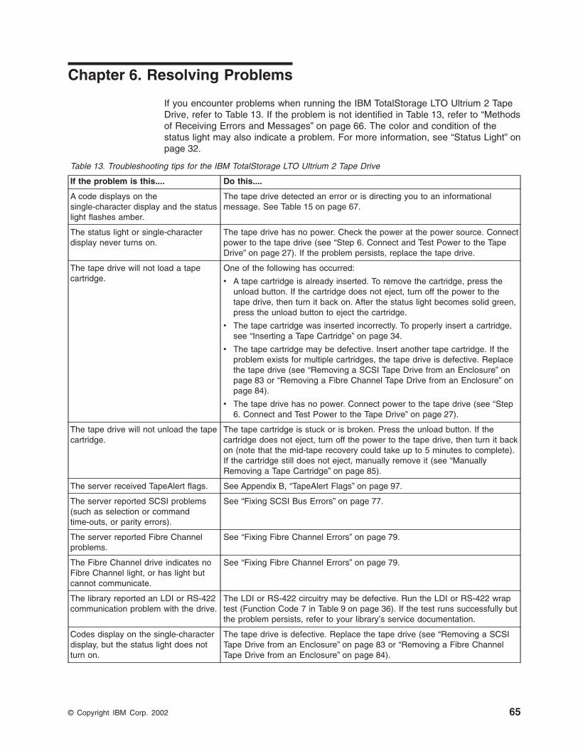
Chapter 6. Resolving Problems
If you encounter problems when running the IBM TotalStorage LTO Ultrium 2 TapeDrive, refer to Table 13. If the problem is not identified in Table 13, refer to “Methodsof Receiving Errors and Messages” on page 66. The color and condition of thestatus light may also indicate a problem. For more information, see “Status Light” onpage 32.
Table 13. Troubleshooting tips for the IBM TotalStorage LTO Ultrium 2 Tape Drive
If the problem is this.... Do this....
A code displays on thesingle-character display and the statuslight flashes amber.
The tape drive detected an error or is directing you to an informationalmessage. See Table 15 on page 67.
The status light or single-characterdisplay never turns on.
The tape drive has no power. Check the power at the power source. Connectpower to the tape drive (see “Step 6. Connect and Test Power to the TapeDrive” on page 27). If the problem persists, replace the tape drive.
The tape drive will not load a tapecartridge.
One of the following has occurred:
v A tape cartridge is already inserted. To remove the cartridge, press theunload button. If the cartridge does not eject, turn off the power to thetape drive, then turn it back on. After the status light becomes solid green,press the unload button to eject the cartridge.
v The tape cartridge was inserted incorrectly. To properly insert a cartridge,see “Inserting a Tape Cartridge” on page 34.
v The tape cartridge may be defective. Insert another tape cartridge. If theproblem exists for multiple cartridges, the tape drive is defective. Replacethe tape drive (see “Removing a SCSI Tape Drive from an Enclosure” onpage 83 or “Removing a Fibre Channel Tape Drive from an Enclosure” onpage 84).
v The tape drive has no power. Connect power to the tape drive (see “Step6. Connect and Test Power to the Tape Drive” on page 27).
The tape drive will not unload the tapecartridge.
The tape cartridge is stuck or is broken. Press the unload button. If thecartridge does not eject, turn off the power to the tape drive, then turn it backon (note that the mid-tape recovery could take up to 5 minutes to complete).If the cartridge still does not eject, manually remove it (see “ManuallyRemoving a Tape Cartridge” on page 85).
The server received TapeAlert flags. See Appendix B, “TapeAlert Flags” on page 97.
The server reported SCSI problems(such as selection or commandtime-outs, or parity errors).
See “Fixing SCSI Bus Errors” on page 77.
The server reported Fibre Channelproblems.
See “Fixing Fibre Channel Errors” on page 79.
The Fibre Channel drive indicates noFibre Channel light, or has light butcannot communicate.
See “Fixing Fibre Channel Errors” on page 79.
The library reported an LDI or RS-422communication problem with the drive.
The LDI or RS-422 circuitry may be defective. Run the LDI or RS-422 wraptest (Function Code 7 in Table 9 on page 36). If the test runs successfully butthe problem persists, refer to your library’s service documentation.
Codes display on the single-characterdisplay, but the status light does notturn on.
The tape drive is defective. Replace the tape drive (see “Removing a SCSITape Drive from an Enclosure” on page 83 or “Removing a Fibre ChannelTape Drive from an Enclosure” on page 84).
© Copyright IBM Corp. 2002 65
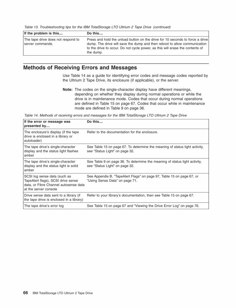
Table 13. Troubleshooting tips for the IBM TotalStorage LTO Ultrium 2 Tape Drive (continued)
If the problem is this.... Do this....
The tape drive does not respond toserver commands.
Press and hold the unload button on the drive for 10 seconds to force a drivedump. The drive will save the dump and then reboot to allow communicationto the drive to occur. Do not cycle power, as this will erase the contents ofthe dump.
Methods of Receiving Errors and MessagesUse Table 14 as a guide for identifying error codes and message codes reported bythe Ultrium 2 Tape Drive, its enclosure (if applicable), or the server.
Note: The codes on the single-character display have different meanings,depending on whether they display during normal operations or while thedrive is in maintenance mode. Codes that occur during normal operationsare defined in Table 15 on page 67. Codes that occur while in maintenancemode are defined in Table 9 on page 36.
Table 14. Methods of receiving errors and messages for the IBM TotalStorage LTO Ultrium 2 Tape Drive
If the error or message waspresented by....
Do this....
The enclosure’s display (if the tapedrive is enclosed in a library orautoloader)
Refer to the documentation for the enclosure.
The tape drive’s single-characterdisplay and the status light flashesamber
See Table 15 on page 67. To determine the meaning of status light activity,see “Status Light” on page 32.
The tape drive’s single-characterdisplay and the status light is solidamber
See Table 9 on page 36. To determine the meaning of status light activity,see “Status Light” on page 32.
SCSI log sense data (such asTapeAlert flags), SCSI drive sensedata, or Fibre Channel autosense dataat the server console
See Appendix B, “TapeAlert Flags” on page 97, Table 15 on page 67, or“Using Sense Data” on page 71.
Drive sense data sent to a library (ifthe tape drive is enclosed in a library)
Refer to your library’s documentation, then see Table 15 on page 67.
The tape drive’s error log See Table 15 on page 67 and “Viewing the Drive Error Log” on page 76.
66 IBM TotalStorage LTO Ultrium 2 Tape Drive

Descriptions and Corrective Actions for Errors and MessagesTable 15 gives descriptions of the errors and messages that pertain to the Ultrium 2Tape Drive, and tells what to do when you receive them.
Attention: If the tape drive detects a permanent error and displays an error codeother than 0, it automatically performs a drive dump. If you force a drive dump, theexisting dump will be overwritten and data will be lost. After you force a drive dump,do not turn off the power to the tape drive or you may lose the dump data.
Table 15. Codes for error conditions and informational messages for the IBM TotalStorage LTO Ultrium 2 TapeDrive. The single-character display clears if you power-off the drive.
Code Cause and Action
0 No error occurred and no action is required. This code displays:
v When power is cycled (turned off, then on) to the tape drive.
v When diagnostics have finished running and no error occurred.
Note: The single-character display is blank during normal operation of the tape drive.
1 Cooling problem. The tape drive detected that the recommended operating temperature wasexceeded. Perform the following action:
1. If a fan is present in the enclosure, ensure that it is rotating and is quiet. If not, replace the fan(for instructions about replacing the fan, see your enclosure’s documentation).
2. Remove any blockage that prevents air from flowing freely through the tape drive.
3. Ensure that the operating temperature and airflow is within the specified range (see Chapter 2,“Specifications” on page 11).
4. If the operating temperature is within the specified range and the problem persists, replace thetape drive.
The error code clears when you power-off the tape drive or place it in maintenance mode.
2 Power problem. The tape drive detected that the externally supplied power is either approachingthe specified voltage limits (the drive is still operating) or is outside the specified voltage limits (thedrive is not operating). Perform the following action:
1. Ensure that the power connector is properly seated.
2. Ensure that the proper dc voltages are being applied within the tolerances allowed (seeChapter 2, “Specifications” on page 11).
3. If the proper voltages are being applied but the problem persists, replace the tape drive.
The error code clears when you power-off the tape drive or place it in maintenance mode.
Chapter 6. Resolving Problems 67

Table 15. Codes for error conditions and informational messages for the IBM TotalStorage LTO Ultrium 2 TapeDrive (continued). The single-character display clears if you power-off the drive.
Code Cause and Action
3 Firmware problem. The tape drive determined that a firmware error occurred. Perform the followingaction:
1. Collect a drive dump from one of the following:Note: Do not force a new dump; the tape drive has already created one.
v Server’s SCSI or Fibre Channel interface by using a device driver utility or system tool. Toobtain a dump, determine whether your server is installed with a utility that can read filesfrom the server’s memory. If it is, use that utility to obtain the dump. For information aboutusing IBM’s utility programs to obtain drive dumps, see the IBM Ultrium Device DriversInstallation and User’s Guide. To determine where to send a file that contains a drive dumpto be analyzed, contact your OEM Product Application Engineer (PAE).
v Enclosure (refer to the procedures for reading a drive dump in your enclosure’sdocumentation)
v Ultrium 2 Tape Drive (to read a drive dump, use Function Code 5 in Table 9 on page 36)
2. Power the tape drive off and on, then retry the operation that produced the error.
3. If the problem persists, download new firmware and retry the operation.
4. If the problem persists, send the drive dump that you collected in step 1 to your OEM ProductApplication Engineer (PAE).
The error code clears when you power-off the tape drive or place it in maintenance mode.
4 Firmware or tape drive problem. The tape drive determined that a firmware or tape drive hardwarefailure occurred. Perform the following action:
1. Collect a drive dump from one of the following:Note: Do not force a new dump; one already exists.
v Server’s SCSI or Fibre Channel interface by using a device driver utility or system tool. Toobtain a dump, determine whether your server is installed with a utility that can read filesfrom the server’s memory. If it is, use that utility to obtain the dump. For information aboutusing IBM’s utility programs to obtain drive dumps, see the IBM Ultrium Device DriversInstallation and User’s Guide. To determine where to send a file that contains a drive dumpto be analyzed, contact your OEM Product Application Engineer (PAE).
v Enclosure (refer to the procedures for reading a drive dump in your enclosure’sdocumentation)
v Ultrium 2 Tape Drive (to read a drive dump, use Function Code 5 in Table 9 on page 36)
2. Power the tape drive off and on, then retry the operation that produced the error. The errorcode clears when you power-off the tape drive or place it in maintenance mode.
3. If the problem persists, download new firmware and retry the operation; if new firmware is notavailable, replace the tape drive.
5 Tape drive hardware problem. The drive determined that a tape path or read/write error occurred.To prevent damage to the drive or tape, the drive will not allow you to insert a cartridge if thecurrent cartridge was successfully ejected. The error code may clear when you cycle power to thetape drive or place it in maintenance mode. If the problem persists, replace the tape drive.
68 IBM TotalStorage LTO Ultrium 2 Tape Drive

Table 15. Codes for error conditions and informational messages for the IBM TotalStorage LTO Ultrium 2 TapeDrive (continued). The single-character display clears if you power-off the drive.
Code Cause and Action
6 Tape drive or media error. The drive determined that an error occurred, but it cannot isolate theerror to faulty hardware or to the tape cartridge. Perform the following action:
For Problems with Writing Data:
If the problem occurred while the drive was writing data to the tape, and if you know the volumeserial number (located on the cartridge label) of the tape cartridge loaded in the drive when theproblem occurred, retry the operation with a different cartridge:v If the operation succeeds, the original cartridge was defective. Copy data from the defective
cartridge and discard it.v If the operation fails and another drive is available, insert the cartridge into the other drive and
retry the operation.– If the operation fails, discard the defective cartridge.– If the operation succeeds, insert a scratch cartridge into the first drive and run the tape drive
diagnostics (see Function Code 1 in Table 9 on page 36).- If the diagnostics fail, replace the drive.- If the diagnostics succeed, the error was temporary.
v If the operation fails and another drive is not available, insert a scratch cartridge into the driveand run the tape drive diagnostics (see Function Code 1 in Table 9 on page 36).– If the diagnostics fail, replace the drive.– If the diagnostics succeed, discard the cartridge.
If the problem occurs with multiple tape cartridges or if you do not know the tape cartridge’svolume serial number, run the tape drive diagnostics (see Function Code 1 in Table 9 on page 36):v If the diagnostics fail, replace the tape drive.v If the diagnostics succeed, run the Test Head diagnostic (see Function Code H in Table 9 on
page 36).– If the Test Head diagnostic fails, replace the tape drive.– If the Test Head diagnostic succeeds, replace the cartridges that caused the problem.
The error code clears when you remove the tape cartridge or place the drive in maintenance mode.
For Problems with Reading Data:
If the problem occurred while the drive was reading data from the tape, and if you know the volumeserial number of the tape cartridge, perform one of the following procedures:v If another drive is available, insert the cartridge into the other drive and retry the operation:
– If the operation fails, discard the defective cartridge.– If the operation succeeds, insert a scratch cartridge into the first drive and run the tape drive
diagnostics (see Function Code 1 in Table 9 on page 36):- If the diagnostics fail, replace the drive.- If the diagnostics succeed, the error was temporary.
v If another drive is not available, insert a scratch cartridge into the drive and run the tape drivediagnostics (see Function Code 1 in Table 9 on page 36):– If the diagnostics fail, replace the drive.– If the diagnostics succeed, discard the cartridge.
If the problem occurs with multiple tape cartridges or if you do not know the tape cartridge’svolume serial number, run the tape drive diagnostics (see Function Code 1 in Table 9 on page 36):v If the diagnostics fail, replace the tape drive.v If the diagnostics succeed, run the Test Head diagnostic (see Function Code H in Table 9 on
page 36).– If the Test Head diagnostic fails, replace the tape drive.– If the Test Head diagnostic succeeds, replace the cartridges that caused the problem.
The error code clears when you remove the tape cartridge or place the drive in maintenance mode.
Chapter 6. Resolving Problems 69
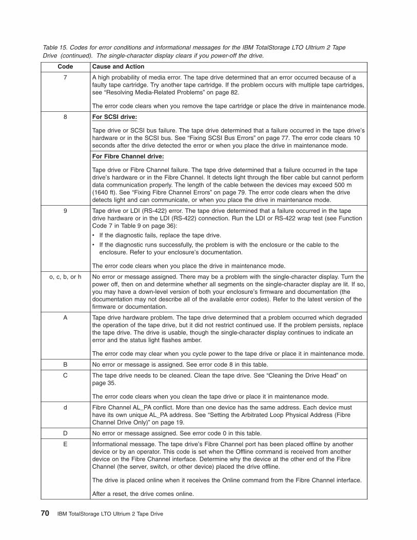
Table 15. Codes for error conditions and informational messages for the IBM TotalStorage LTO Ultrium 2 TapeDrive (continued). The single-character display clears if you power-off the drive.
Code Cause and Action
7 A high probability of media error. The tape drive determined that an error occurred because of afaulty tape cartridge. Try another tape cartridge. If the problem occurs with multiple tape cartridges,see “Resolving Media-Related Problems” on page 82.
The error code clears when you remove the tape cartridge or place the drive in maintenance mode.
8 For SCSI drive:
Tape drive or SCSI bus failure. The tape drive determined that a failure occurred in the tape drive’shardware or in the SCSI bus. See “Fixing SCSI Bus Errors” on page 77. The error code clears 10seconds after the drive detected the error or when you place the drive in maintenance mode.
For Fibre Channel drive:
Tape drive or Fibre Channel failure. The tape drive determined that a failure occurred in the tapedrive’s hardware or in the Fibre Channel. It detects light through the fiber cable but cannot performdata communication properly. The length of the cable between the devices may exceed 500 m(1640 ft). See “Fixing Fibre Channel Errors” on page 79. The error code clears when the drivedetects light and can communicate, or when you place the drive in maintenance mode.
9 Tape drive or LDI (RS-422) error. The tape drive determined that a failure occurred in the tapedrive hardware or in the LDI (RS-422) connection. Run the LDI or RS-422 wrap test (see FunctionCode 7 in Table 9 on page 36):
v If the diagnostic fails, replace the tape drive.
v If the diagnostic runs successfully, the problem is with the enclosure or the cable to theenclosure. Refer to your enclosure’s documentation.
The error code clears when you place the drive in maintenance mode.
o, c, b, or h No error or message assigned. There may be a problem with the single-character display. Turn thepower off, then on and determine whether all segments on the single-character display are lit. If so,you may have a down-level version of both your enclosure’s firmware and documentation (thedocumentation may not describe all of the available error codes). Refer to the latest version of thefirmware or documentation.
A Tape drive hardware problem. The tape drive determined that a problem occurred which degradedthe operation of the tape drive, but it did not restrict continued use. If the problem persists, replacethe tape drive. The drive is usable, though the single-character display continues to indicate anerror and the status light flashes amber.
The error code may clear when you cycle power to the tape drive or place it in maintenance mode.
B No error or message is assigned. See error code 8 in this table.
C The tape drive needs to be cleaned. Clean the tape drive. See “Cleaning the Drive Head” onpage 35.
The error code clears when you clean the tape drive or place it in maintenance mode.
d Fibre Channel AL_PA conflict. More than one device has the same address. Each device musthave its own unique AL_PA address. See “Setting the Arbitrated Loop Physical Address (FibreChannel Drive Only)” on page 19.
D No error or message assigned. See error code 0 in this table.
E Informational message. The tape drive’s Fibre Channel port has been placed offline by anotherdevice or by an operator. This code is set when the Offline command is received from anotherdevice on the Fibre Channel interface. Determine why the device at the other end of the FibreChannel (the server, switch, or other device) placed the drive offline.
The drive is placed online when it receives the Online command from the Fibre Channel interface.
After a reset, the drive comes online.
70 IBM TotalStorage LTO Ultrium 2 Tape Drive

Table 15. Codes for error conditions and informational messages for the IBM TotalStorage LTO Ultrium 2 TapeDrive (continued). The single-character display clears if you power-off the drive.
Code Cause and Action
F The tape drive determined that no light is being received over the Fibre Channel. See “Fixing FibreChannel Errors” on page 79.
The error code clears when the drive detects light or when you place the drive in maintenancemode.
Using Sense DataWhen a tape drive encounters an error, it makes sense data available. You can useIBM device drivers to examine the sense data and determine errors. Instructions fordownloading, installing, and properly configuring the IBM device drivers areavailable in the IBM Ultrium Device Drivers Installation and User’s Guide. The IBMdevice drivers may conflict with some commercial software applications unlessproperly configured. To avoid conflicts on Windows operating systems, refer to yourdevice driver’s procedures for setting the driver to manual startup mode. Forapplications that use Open Systems device drivers that are provided by IBM (forexample, AIX, Linux, Sun Solaris, HP-UX, Windows/NT, and Windows 2000), theIBM Ultrium Device Drivers Installation and User’s Guide contains information abouthow to obtain sense data after an error has occurred.
If your application uses other device drivers, see the appropriate documentation forthose drivers to obtain the sense data.
Raw sense data (as returned from the Ultrium 2 Tape Drive) is documented in theIBM TotalStorage LTO Ultrium Tape Drive SCSI Reference.
In addition to device drivers, other methods exist for obtaining sense data and errorinformation. The sections that follow describe alternatives for gathering suchinformation from the IBM AS/400, Eserver iSeries, RS/6000, and Eserver
pSeries servers.
Obtaining Error Information from the AS/400 or iSeries with RISCProcessorFor OS/400, sense data is provided by the System Service Tools application. Toobtain error information from the AS/400 or iSeries by using the tool:
1. On the command entry line of the AS/400 Main Menu, type STRSST (StartSystem Service Tools) and press Enter.
2. Select Start a service tool.
3. Select Product activity log.
4. Select Analyze log.
5. On the Select System Data menu, select the Magnetic media option thenspecify the time period for searching the error log.
6. On the Select Analysis Report Options menu, specify a Device selection of 3580and press Enter. Leave all other options at their default values.
7. On the Log Analysis Report menu, select the Display report option to display thedesired error log. Figure 24 on page 72 shows a sample error log.
Chapter 6. Resolving Problems 71

8. Press F4 to view the sense data (see the example in Figure 25).
Obtaining Error Information from the RS/6000 or pSeriesThe AIX® Tape and Media Changer Device Driver for the IBM RS/6000 or IBMEserver pSeries provides logging to the system error log for a variety of errors.You can view the error log by issuing the AIX errpt command. Figure 26 onpage 73 displays a sample drive error log; Figure 27 on page 74 displays a sampleSCSI bus error log.
To view the error log:
1. At the AIX command line, type errpt -a |pg to display a detailed report.
2. Press Enter to scroll through the error log.
3. Type q to quit the error log at any time.
Display Detail Report for Resource
Serial ResourceName Type Model Number NameTAP07 3580 002 00-00000 TAP07
Log ID . . . . . . . . . : 00452B54 Sequence . . . . . . : 4732468Date . . . . . . . . . . : 08/14/02 Time . . . . . . . . : 09:50:21Reference code . . . . . : 9210 Secondary code . . . : 00000000Table ID . . . . . . . . : 63A00001 IPL source/state . . : B/3
Class . . . . . . . . . . : PermanentSystem Ref Code . . . . . : 63A09210Illegal or unsupported tape unit response
Press Enter to continue.
F3=Exit F4=Additional Information F6=Hexadecimal reportF9=Address Information F10=Previous detail report F12=Cancel
Figure 24. Example of an error log from the AS/400 or IBM Eserver iSeries
Display Additional Information for Resource
Serial ResourceName Type Model Number NameTAP07 3580 002 00-00000 TAP07
SENSE DATA FOLLOWS. . . . . :DATA OFFSET 0 1 2 3 4 5 6 7 8 9 A B C D E F00000000 70000500 0000001C 00000000 240000C000000010 00020000 00000000 00000000 0000000000000020 058B0000
Figure 25. Example of sense data from the AS/400 or IBM Eserver iSeries
72 IBM TotalStorage LTO Ultrium 2 Tape Drive

Example of a Drive Error Log:
In the SENSE DATA area of Figure 26, entries in bold are defined as follows:
Hexadecimal Code Description
01 SCSI Command
0000, 0200, 0000 Command parameters
70 Byte 0 of SCSI sense data
03 Sense key
5200 ASC/ASCQ (Additional Sense Code/Additional Sense CodeQualifier)
20B0 FSC (Fault Symptom Code)
058A Relative LPOS
02 SCSI ID
LABEL: TAPE_ERR1IDENTIFIER: 4865FA9B
Date/Time: Wed Oct 11 11:39:43Sequence Number: 25264Machine ID: 000D090D4C00Node ID: tsmClass: HType: PERMResource Name: rmt2Resource Class: tapeResource Type: LTOLocation: 40-60-00-2,0VPD:
Manufacturer................IBMMachine Type and Model......ULT3580-TD2Serial Number...............1300015078Device Specific.(FW)........0B70 (Firmware Level)
DescriptionTAPE OPERATION ERROR
Probable CausesTAPE
User CausesMEDIA DEFECTIVEDIRTY READ/WRITE HEAD
Recommended ActionsFOR REMOVABLE MEDIA, CHANGE MEDIA AND RETRYPERFORM PROBLEM DETERMINATION PROCEDURES
Detail DataSENSE DATA0602 0000 0100 0000 0200 0000 0000 0000 0000 0000 7000 0300 0000 001C 0000 00005200 0700 20B0 0000 0000 0000 0000 0000 0000 0000 058A 0200 0000 0000 0000 00000000 0000 0000 0000 0000 0000 0000 0000 0000 0000 0000 0000 0000 0000 0000 00000000 0000 0000 0000 0000 0000 0000 0000 0000 0000 0000 0000 0000 0000 0000 00000000 0000 0000 0000 0000 0000 0000 0000 0000 0000 0000 0000 0000 0000
Figure 26. Example of an AIX ERRPT Drive Error Log
Chapter 6. Resolving Problems 73
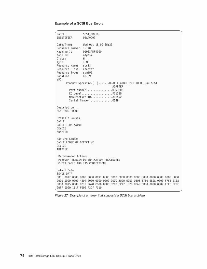
Example of a SCSI Bus Error:
LABEL: SCSI_ERR10IDENTIFIER: 0BA49C99
Date/Time: Wed Oct 18 09:55:32Sequence Number: 16140Machine Id: 00003ABF4C00Node Id: ofgtsmClass: HType: TEMPResource Name: scsi3Resource Class: adapterResource Type: sym896Location: 40-59VPD:
Product Specific.( ).......DUAL CHANNEL PCI TO ULTRA2 SCSIADAPTER
Part Number.................03N3606EC Level....................F71335Manufacture ID..............A16592Serial Number...............0749
DescriptionSCSI BUS ERROR
Probable CausesCABLECABLE TERMINATORDEVICEADAPTER
Failure CausesCABLE LOOSE OR DEFECTIVEDEVICEADAPTER
Recommended ActionsPERFORM PROBLEM DETERMINATION PROCEDURESCHECK CABLE AND ITS CONNECTIONS
Detail DataSENSE DATA0001 0017 0000 0000 0000 0091 0000 0000 0000 0000 0000 0000 0000 0000 0000 00000000 0000 0000 4304 0000 0000 0000 0000 2000 0003 0203 6760 9808 0000 F7FB E1B80000 0015 000B 0210 0678 C800 0000 8200 8277 1B20 00A2 ED00 0000 0002 FFFF FFFF00FF 0000 111F F000 F3DF F110
Figure 27. Example of an error that suggests a SCSI bus problem
74 IBM TotalStorage LTO Ultrium 2 Tape Drive

Obtaining a Drive DumpYou can obtain a drive dump by selecting a function code on the IBM TotalStorageLTO Ultrium 2 Tape Drive or by using a device driver utility (or a system tool) on theserver. The sections that follow describe each method.
Using the Drive to Obtain a DumpTo obtain a drive dump directly from the IBM TotalStorage LTO Ultrium 2 TapeDrive:
1. Make sure that no cartridge is in the drive.
2. Within a 1.5-second interval, press the unload button three times. The statuslight becomes solid amber, which means that the drive is in maintenance mode.
3. Press the unload button once per 1.5 seconds until 5 appears in thesingle-character display.
4. To select the function, press and hold the unload button for 3 seconds. After yourelease the button, C flashes. Within 60 seconds, insert a scratch data cartridgethat is not write-protected. After you insert the cartridge, 5 flashes and the drivewrites the dump data to the scratch tape. When the function is complete, thedrive rewinds and unloads the tape.
5. Insert the tape into a drive.
6. From the server, issue the SCSI READ command to read the dump from thetape to a file or electronic image (you may need to issue the command severaltimes to read the complete dump).
7. To determine where to send the file for analysis, contact your OEM ProductApplication Engineer (PAE).
Using a Device Driver Utility to Obtain a DumpTo obtain a drive dump by using a device driver utility, determine whether yourserver is installed with a utility that can read files from the server’s memory. If it is,use that utility to obtain the drive dump.
For information about using IBM’s utility programs to obtain drive dumps, see theIBM Ultrium Device Drivers Installation and User’s Guide.
To determine where to send a file that contains a drive dump to be analyzed,contact your OEM Product Application Engineer (PAE).
Chapter 6. Resolving Problems 75

Viewing the Drive Error LogThe Ultrium 2 Tape Drive keeps an error log that you can use to identify and correcterrors. The log contains the 10 most recent error codes, which appear (one at atime) on the single-character display.
To view the drive error log:
1. Make sure that no cartridge is in the drive.
2. Within a 1.5-second interval press the unload button three times. The statuslight becomes solid amber, which means that the drive is in maintenance mode.
3. Press the unload button once per 1.5 seconds until 9 appears in thesingle-character display.
4. Press and hold the unload button for 3 seconds to view the most recent errorcode.
5. Refer to Table 15 on page 67 to determine the meaning of the code and theaction to take.
6. Press the unload button to view the next error code. (The codes are ordered;the most recent is presented first and the oldest (tenth) is presented last.)
7. Continue to press the unload button until the 10 error codes have beendisplayed. After you display the tenth error code, the drive automatically exitsmaintenance mode.
To redisplay the error codes, repeat steps 1 through 7.
76 IBM TotalStorage LTO Ultrium 2 Tape Drive

Resolving Problems Reported by the ServerThe procedure for fixing SCSI bus or Fibre Channel errors varies, depending onwhether the error is consistent or intermittent, and whether your configurationcontains single or multiple Ultrium 2 Tape Drives. The sections that follow describehow to fix each type of error.
Fixing SCSI Bus Errors
Note: If you are using a Storage Area Network (SAN) Data Gateway to convert adrive with a SCSI interface to a Fibre Channel interface, ensure that theproblem is occurring between the SAN Data Gateway and the drive byrunning the SCSI wrap test on the drive and running the SCSI loopback teston the SAN Data Gateway. (To run the SCSI wrap test, see Function Code 6in Table 9 on page 36; to run the SCSI loopback test, refer to the sectionabout that test in the IBM Storage Area Network Gateway Module Setup,Operator, and Service Guide.) If you are using a Fibre Channel drive and arehaving problems, see “Fixing Fibre Channel Errors” on page 79.
Fixing a Consistent Error with a Single Drive on a SCSI Bus1. Ensure that the power is on to the Ultrium 2 Tape Drive.
2. Ensure that the tape drive’s SCSI address is the same as the SCSI addressassigned by the server.
3. Run the SCSI wrap test (see Function Code 6 in Table 9 on page 36).
v If the test runs successfully, replace the SCSI terminator first, then the SCSIcable and the interposer (if installed). Repeat the operation that caused theerror. If you replaced the SCSI terminator or SCSI cable and the problempersists, the fault is with the server’s hardware or software. To isolate thecause of the failure, refer to the server’s service documentation.
v If the test fails, replace the tape drive (see “Removing a SCSI Tape Drivefrom an Enclosure” on page 83).
Fixing a Consistent Error with Multiple Drives on a SCSI BusWhen a consistent error occurs in a configuration that has multiple tape drives onthe SCSI bus, you must determine if the problem exists with more than one tapedrive. If the problem is with all of the devices on the SCSI bus, the bus is stuck in aSCSI phase and cannot change to another phase or the SCSI cable from the serverto the first device is defective.
1. Ensure that the SCSI cable from the server to the first device is connected.
2. Disconnect all but the first tape drive on the SCSI bus. Move the terminator tothe first SCSI device.
3. Run a device driver utility (such as IBM’s ntutil or tapeutil) to determine whetherthe error will occur.
v If the error occurs, run the SCSI wrap test on the first tape drive (seeFunction Code 6 in Table 9 on page 36).
– If the test runs successfully, replace the SCSI terminator first, then theSCSI cable and the interposer (if installed) to the first tape drive. Repeatthe operation that caused the error. If you replaced the SCSI terminator orSCSI cable and the problem persists, the fault is with the server’shardware or software. To isolate the cause of the failure, refer to theserver’s service documentation.
– If the test fails, replace the tape drive (see “Removing a SCSI Tape Drivefrom an Enclosure” on page 83).
Chapter 6. Resolving Problems 77

v If the error does not occur, connect one tape drive at a time back to the busand repeat step 3 for each tape drive until you can identify which drive isdefective.
Note: Ensure that the SCSI terminator is always on the last tape drive on theSCSI bus.
4. Determine if the problem is with only one tape drive or with two or more tapedrives.
v If the problem is with only one tape drive, run the SCSI wrap test on that tapedrive (see Function Code 6 in Table 9 on page 36).
– If the test runs successfully, replace the SCSI terminator first, then theSCSI cable to that tape drive and interposer (if installed).
– If the test fails, replace the tape drive (see “Removing a SCSI Tape Drivefrom an Enclosure” on page 83).
v If the problem is with two or more tape drives, locate the first tape drive thathas the error and replace the SCSI cable that connects the tape drive andthe interposer (if installed).
Fixing an Intermittent Error with a Single Drive on a SCSI Bus1. Replace the SCSI terminator on the tape drive.
2. Run the operation that caused the error. If the problem persists, the problemmay be with the cable.
3. Isolate which cable is causing the problem by replacing one cable at a time andrunning the operation that caused the error after each replacement. If theproblem persists after all cables have been replaced, the problem may be withthe Ultrium 2 Tape Drive.
4. Replace the tape drive (see “Removing a SCSI Tape Drive from an Enclosure”on page 83). If the problem persists, the problem is with your server. Consultyour server’s documentation.
Fixing an Intermittent Error with Multiples Drives on a SCSI BusRefer to the server’s error logs to determine which tape drive is the source of theproblem:
v If only one tape drive is reporting a SCSI failure, replace that tape drive (see“Removing a SCSI Tape Drive from an Enclosure” on page 83).
v If multiple tape drives are reporting SCSI failures, the problem may be with theterminator or the SCSI cables:
– Replace the terminator and run the operation that caused the error. If theproblem persists, the problem may be with the cables.
– Isolate which cable is causing the problem by replacing one cable at a timeand run the operation that caused the error after each replacement.
78 IBM TotalStorage LTO Ultrium 2 Tape Drive

Fixing Fibre Channel ErrorsIf you are connected to a Fibre Channel Storage Area Network (SAN) by using aSAN Data Gateway, use the IBM Storage Area Network Gateway Module Setup,Operator, and Service Guide to determine whether the problem is occurringbetween the drive and the SAN Data Gateway. If you are using a SCSI drive andare having SCSI problems, see “Fixing SCSI Bus Errors” on page 77.
Starting Problem DeterminationBefore starting the problem determination, perform the following steps:
1. Determine the type of Fibre Channel topology that you are using (see page 6).Ensure that the drive and the port to which it is attached are configured incompatible topologies.
2. Using this guide or the service guides of associated switch, hub, or fiberproducts, try to determine where the problem exists (whether in the drive, cable,or the device to which the drive and cable attach).
3. Ensure that the configuration and software levels are supported (see “FibreChannel Attachment” on page 6).
4. Ensure that the Fibre Channel cables are installed correctly. Refer to theappropriate steps in Chapter 3, “Installing the Tape Drive” on page 13.
5. Go to one of the following procedures:
v “Fixing a Consistent Error with a Single Drive on a Fibre Channel Loop”
v “Fixing a Consistent Error with Multiple Drives on a Fibre Channel Loop” onpage 80
v “Fixing a Consistent Error in a Point-to-Point Topology” on page 80
v “Fixing Intermittent Fibre Channel Errors” on page 81
Fixing a Consistent Error with a Single Drive on a Fibre ChannelLoop1. Ensure that the tape drive is powered on.
2. Verify that the tape drive’s serial number is the same as the drive serial numberthat the server program is using.
3. Ensure that the drive’s Fibre Channel AL_PA is set correctly, that it is on theloop, and that it is not being used by another device (see “Setting the ArbitratedLoop Physical Address (Fibre Channel Drive Only)” on page 19). The tape drivemust be able to detect light and communicate with the server.
4. Run the Fibre Channel wrap test at the drive’s Fibre Channel connector (seeFunction Code 6 in Table 9 on page 36).
v If the test fails, replace the tape drive.
v If the test is successful, go to step 5.
5. Run the Fibre Channel wrap test at the end of the fiber cable (see FunctionCode 6 in Table 9 on page 36).
v If the test fails, replace the fiber cable.
v If the test is successful, go to step 6.
6. Check the Fibre Channel cable connection at the server.
7. Using a device driver utility such as ntutil or tapeutil, verify that the drive isproperly configured and available at the server.
8. If the problem persists, the fault may be with the server’s hardware or software.Refer to your server’s service manual.
Chapter 6. Resolving Problems 79

9. When the problem is corrected (or determined to be a server problem), restoreall of the fiber cables to their correct position.
Fixing a Consistent Error with Multiple Drives on a Fibre ChannelLoopUse the following procedure to determine if all of the drives on the Fibre Channelhave the problem:
1. Use a device driver utility (such as ntutil or tapeutil) to verify that the drive isavailable and properly configured at the server.
2. Determine the type of Fibre Channel topology that you are using (see page 6).
3. Using this guide or the service guides of associated switch, hub, or fiberproducts, try to isolate which part of the Fibre Channel Storage Area Network(SAN) is experiencing problems.
4. Perform one of the following:
v If the problem exists on a small number of drives, go to “Fixing a ConsistentError with a Single Drive on a Fibre Channel Loop” on page 79.
v If the problem exists with a large number of drives, perform the followingsteps:
a. Disconnect all except one failing drive on the Fibre Channel.
b. Run the Fibre Channel wrap test to determine if a failure occurs on thatdrive (see Function Code 6 in Table 9 on page 36). If it does, perform theprocedure in “Fixing a Consistent Error with a Single Drive on a FibreChannel Loop” on page 79.
c. Continue to connect one drive at a time to the Fibre Channel loop.
5. When the problem is corrected, restore all of the Fibre Channel cables to theircorrect position.
Fixing a Consistent Error in a Point-to-Point Topology1. Ensure that the tape drive is powered on.
2. Verify that the tape drive’s serial number is the same as the drive serial numberthat the server program is using.
3. Ensure that the drive is connected to the host or switch. The drive must be ableto detect light and communicate with the server.
4. Run the Fibre Channel wrap test at the drive’s Fibre Channel connector (seeFunction Code 6 in Table 9 on page 36).
v If the test fails, replace the tape drive.
v If the test is successful, go to step 5.
5. Run the Fibre Channel wrap test at the end of the fiber cable (see FunctionCode 6 in Table 9 on page 36).
v If the test fails, replace the fiber cable.
v If the test is successful, go to step 6.
6. Check the Fibre Channel cable connection at the server.
7. Using a device driver utility such as ntutil or tapeutil, verify that the drive isproperly configured and available at the server.
8. If the problem persists, the fault may be with the server’s hardware or software.Refer to your server’s service manual.
9. When the problem is corrected (or determined to be a server problem), restoreall of the fiber cables to their correct position.
80 IBM TotalStorage LTO Ultrium 2 Tape Drive
Fixing Intermittent Fibre Channel Errors1. Determine the type of Fibre Channel topology that you are using (see page 6).
2. Ensure that the configuration and software levels are supported (see “FibreChannel Attachment” on page 6).
3. Check that each Fibre Channel cable does not exceed 500 m (1640 ft).
4. Ensure that all Fibre Channel cables are installed correctly. Refer to theappropriate steps in Chapter 3, “Installing the Tape Drive” on page 13.
5. Using this guide or the service guides of associated switch, hub, or fiberproducts, determine that a problem exists between the drive, drive cable, andthe device to which they attach. Try to isolate which part of the Storage AreaNetwork (SAN) is experiencing problems.
6. Using this guide or the service guides of associated switch, hub, or fiberproducts, verify that the SAN configurations are correct (such as switch zoningfor drive sharing).
7. Obtain all errors reported by the drive to the server (see “Using Sense Data” onpage 71), then contact your OEM Product Application Engineer (PAE) for erroranalysis.
Chapter 6. Resolving Problems 81
Resolving Media-Related ProblemsTo resolve problems that are related to media, the Ultrium 2 Tape Drive’s firmwareincludes:
v Test Cartridge & Media diagnostic that verifies whether a suspect cartridge andits magnetic tape are acceptable for use.
v Statistical Analysis and Reporting System (SARS) to assist in isolating failuresbetween media and hardware. To determine the cause of failure, SARS uses thecartridge performance history that is saved in the cartridge memory (CM) and thedrive performance history that is kept in the drive’s flash erasable programmableread-only memory (EPROM). Any failures that SARS detects are reported asTapeAlert flags on the server (see Appendix B, “TapeAlert Flags” on page 97).
Attention: If you insert the IBM LTO Ultrium Data Cartridge into anothermanufacturer’s tape drive, the SARS data in the cartridge memory may becomelost or invalid.
If you encounter a media-related problem, use the following procedure:
Attention: When you run the Test Cartridge & Media diagnostic, data on thesuspect tape is overwritten. Use only a scratch data cartridge to run the test.
1. If possible, run the tape cartridge in a different tape drive. If the operation in theother tape drive fails and 6 or 7 displays, replace the media. If the operationsucceeds, run the Test Cartridge & Media diagnostic (see Function Code E inTable 9 on page 36).
2. If the Test Cartridge & Media diagnostic fails, replace the media. If it runssuccessfully, clean the tape drive and run the tape drive diagnostics (see“Cleaning the Drive Head” on page 35 and Function Code 1 in Table 9 onpage 36).
3. If the tape drive diagnostics fail, replace the tape drive. If the tape drivediagnostics run successfully, perform the operation that produced the initialmedia error.
82 IBM TotalStorage LTO Ultrium 2 Tape Drive
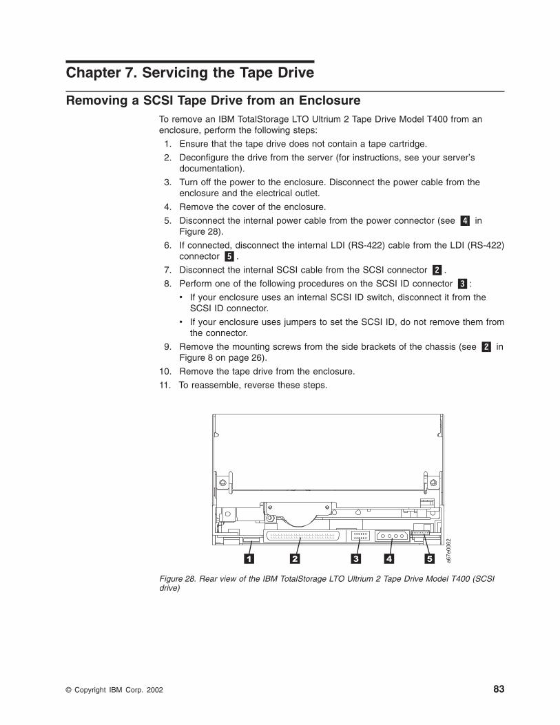
Chapter 7. Servicing the Tape Drive
Removing a SCSI Tape Drive from an EnclosureTo remove an IBM TotalStorage LTO Ultrium 2 Tape Drive Model T400 from anenclosure, perform the following steps:
1. Ensure that the tape drive does not contain a tape cartridge.
2. Deconfigure the drive from the server (for instructions, see your server’sdocumentation).
3. Turn off the power to the enclosure. Disconnect the power cable from theenclosure and the electrical outlet.
4. Remove the cover of the enclosure.
5. Disconnect the internal power cable from the power connector (see �4� inFigure 28).
6. If connected, disconnect the internal LDI (RS-422) cable from the LDI (RS-422)connector �5�.
7. Disconnect the internal SCSI cable from the SCSI connector �2�.
8. Perform one of the following procedures on the SCSI ID connector �3�:
v If your enclosure uses an internal SCSI ID switch, disconnect it from theSCSI ID connector.
v If your enclosure uses jumpers to set the SCSI ID, do not remove them fromthe connector.
9. Remove the mounting screws from the side brackets of the chassis (see �2� inFigure 8 on page 26).
10. Remove the tape drive from the enclosure.
11. To reassemble, reverse these steps.
Figure 28. Rear view of the IBM TotalStorage LTO Ultrium 2 Tape Drive Model T400 (SCSIdrive)
© Copyright IBM Corp. 2002 83

Removing a Fibre Channel Tape Drive from an EnclosureTo remove an IBM TotalStorage LTO Ultrium 2 Tape Drive Model T400F from anenclosure, perform the following steps:
1. Ensure that the tape drive does not contain a tape cartridge.
2. Deconfigure the drive from the server, switch, or hub (for instructions, see thedocumentation for these devices).
3. Turn off the power to the enclosure. Disconnect the power cable from theenclosure and the electrical outlet.
4. Disconnect the internal power cable from the power connector (see �1� inFigure 29).
5. If connected, disconnect the internal LDI (RS-422) cable from the LDI (RS-422)connector �6�.
6. Disconnect the internal fiber cable from the Fibre Channel connector �5�.
7. Disconnect the LID/status connector �3�.
8. Disconnect the FC configuration/status connector �4�.
9. Remove the mounting screws from the side brackets of the chassis (see �2� inFigure 8 on page 26).
10. Remove the tape drive from the enclosure.
11. To reassemble, reverse these steps.
Figure 29. Rear view of the IBM TotalStorage LTO Ultrium 2 Tape Drive Model T400F (FibreChannel drive)
84 IBM TotalStorage LTO Ultrium 2 Tape Drive
Manually Removing a Tape CartridgeIf problem-determination procedures identify the Ultrium 2 Tape Drive as the sourceof a problem, you can optionally perform one of the following:
v Replace the entire unit. For more information, contact your OEM ProductApplication Engineer (PAE).
v Manually remove the cartridge (see “Removing the Cartridge”).
v If you are unable to manually remove the cartridge, contact trained servicepersonnel for assistance. Refer the service personnel to the instructions in“Fixing an Internal Jam” on page 88.
Attention:If you are not a trained service person, do not attempt to open the drivefor repairs. Attempting a repair other than the manual removal of a tapecartridge will void your warranty.
Removing the CartridgeIf a tape cartridge fails to eject from the Ultrium 2 Tape Drive, you can manuallyremove the cartridge. The following tools are required for the procedure:
v 2.5-mm allen wrench
v Small-blade screwdriver or potentiometer-setting tool
v 2-mm hex wrench
v #3 Phillips screwdriver
v Needle-nose pliers
v Flashlight (optional)
Attention: Before performing this procedure, note the following:
v Ensure that you have attempted all normal methods of removing the tapecartridge from the drive. Refer to “Removing a Tape Cartridge” on page 35 andthe troubleshooting tips in Table 13 on page 65.
v This procedure may damage the stuck tape cartridge. If you use this procedure,copy the data from the stuck cartridge to another cartridge. If you choose toreuse the stuck cartridge, refer to the instructions in “Repositioning orReattaching a Leader Pin” on page 55. If you believe the cartridge has beendamaged, replace it.
v Do not use a power screwdriver to perform this procedure because it can destroythe tape.
v Never touch the head or electronic components within the drive. Touching maycause contamination or damage by electrostatic discharge.
Chapter 7. Servicing 85

To manually remove a tape cartridge, perform the following steps:
1. Place the drive so that the front faces you, then tilt it on its left side (seeFigure 30).
2. Locate the access hole at the bottom of the unit (see �1� in Figure 30).
3. Insert a 2.5-mm allen wrench into the access hole and position the wrench sothat it is seated in the screw of the supply reel motor.
4. Push open the door of the tape load compartment and locate the flag �2� onthe drive’s takeup reel.
Attention: In the following step, rotate the allen wrench clockwise, notcounterclockwise. A counterclockwise motion may damage the tape.
5. To determine whether the tape is broken, watch the flag �2� on the drive’stakeup reel while you rotate the allen wrench �1� clockwise (do not let thewrench move counterclockwise):v If you feel resistance to the allen wrench while attempting to turn the supply
reel motor screw clockwise, go to step 7 on page 87.v If the takeup reel turns when you rotate the supply reel motor screw
clockwise with the allen wrench, the tape is not broken. Go to step 6 onpage 87.
v If the takeup reel does not turn when you rotate the supply reel motor screwclockwise with the allen wrench and if supply reel motor screw rotates freely,the tape is broken. You must determine the location of the leader block. Todo so, insert a small-blade screwdriver or potentiometer-setting tool into theaccess hole for the loader motor gear �3�. Rotate the screwdrivercounterclockwise. You may have to rotate for a lengthy period:– If the cartridge moves up, the tape is completely in the cartridge and the
leader block is in the home position. Continue rotating the screwdriveruntil the cartridge ejects. Remove the cartridge.
– If you feel resistance and the cartridge does not move up, the leaderblock is not in the home position. Go to “Fixing an Internal Jam” onpage 88.
Figure 30. Determining whether the tape is broken
86 IBM TotalStorage LTO Ultrium 2 Tape Drive

6. Continue to rotate the allen wrench until you feel resistance. The tape hasbeen rewound as far as it can go without unthreading.
Note: The number of required rotations depends on where the beginning ofthe tape is on the cartridge’s takeup reel. You may have to rotate theallen wrench for a lengthy period.
7. With the allen wrench still inserted into the bottom access hole, insert asmall-blade screwdriver or potentiometer-setting tool into the access hole forthe loader motor gear �3�.
8. While keeping torque on the supply reel motor screw and rotating the allenwrench �1� clockwise, rotate the loader motor gear with the small-bladescrewdriver �3� counterclockwise (see arrow). As you rotate the screwdriver,the allen wrench moves slightly.
9. With the small-blade screwdriver, continue to rotate the loader motor gear inthe unload direction (counterclockwise):
v If you feel no resistance to the allen wrench and the cartridge slowly movesup and out of the tape load compartment to the fully ejected position, theprocedure was successful. Remove the small-blade screwdriver and go tostep 10.
v If you feel resistance to the allen wrench and the cartridge does not move,the loader mechanism is jammed or the leader block is not at the homeposition. Remove the small-blade screwdriver and go to “Fixing an InternalJam” on page 88.
10. Remove the tape cartridge.
11. To ensure that the drive operates properly, refer to page 36 and selectFunction Code 1 - Run Tape Drive Diagnostics.
After you remove the stuck tape cartridge, copy the data on the tape to anothertape. Then, if appropriate, return the stuck tape cartridge in its original packaging orin the packaging from its replacement to your reseller. If the leader pin detachedfrom the tape in the cartridge, go to “Repositioning or Reattaching a Leader Pin” onpage 55.
Chapter 7. Servicing 87

Fixing an Internal Jam
Attention:This procedure must be performed only by trained service personnel.
If problem-determination procedures identify the Ultrium 2 Tape Drive asthe source of a problem, replace the entire unit. If you are not a trainedservice person, do not attempt to open the drive for repairs. Attempting arepair other than the manual removal of a tape cartridge will void yourwarranty.
Before performing this procedure, ensure that you have completed the stepsthat begin on page 86. Do not attempt this procedure until you have completedthese steps.
If you have reached this point, the tape is broken or the leader pin dropped (orlooked like it dropped) from the leader block. To fix these conditions, perform thefollowing procedure.
1. If the drive is mounted in an enclosure, perform the procedure to remove it(see “Removing a SCSI Tape Drive from an Enclosure” on page 83 or“Removing a Fibre Channel Tape Drive from an Enclosure” on page 84).
2. Place the drive on a nonslip surface.
3. Remove the cover of the drive by performing the following steps:
a. Use an appropriate tool to remove the three screws and washers (see �1�in Figure 31 on page 89) that secure the bezel �2�. Remove the bezel.
b. Use a screwdriver to remove the four cover-mounting screws and washers�3�.
c. Remove the cover by lifting it up. Set the cover aside.
88 IBM TotalStorage LTO Ultrium 2 Tape Drive

4. Examine the drive to determine the cause of the problem:
v If the tape is broken, do not attempt repair. Return the drive and the stucktape to your reseller for maintenance (note that your tape will be scrapped).
v If the leader pin dropped from the leader block, go to step 5 on page 90 andcontinue this procedure.
v If the leader block pulled the tape (but not the pin) from the spool so that itlooks like the pin was dropped, go to step 5 on page 90 and continue thisprocedure.
Figure 31. Removing the top cover of the drive
Chapter 7. Servicing 89

5. Place the tape drive so that the front faces you, then tilt it on its left side (seeFigure 32).
6. At the bottom of the drive, locate the access hole (�1� in Figure 32).
Attention: In the following steps, do not allow drive componentsto touch the head �2�. Damage may result to the head.
7. Insert a 2.5-mm allen wrench into the access hole and position the wrench sothat it is seated in the screw of the supply reel motor.
8. With clean needle-nose pliers, grasp the end of the leader pin and pull it out ofthe cartridge so that you can grip it with your fingers (see �3� in Figure 32).
Note: If the leader pin is not connected to the tape, set the pin aside. Afteryou remove the cartridge, reattach the pin (see “Repositioning orReattaching a Leader Pin” on page 55).
Figure 32. Rewinding the leader pin into the tape cartridge
90 IBM TotalStorage LTO Ultrium 2 Tape Drive

9. While keeping the tape taut with your fingers, rotate the allen wrench clockwise�1� to wind the excess tape into the cartridge. Guide the leader pin toward thecartridge and drop it inside the cartridge door. Ensure that no tape is leftoutside of the cartridge. Remove the allen wrench.
Note: Do not attempt to seat the leader pin into the cartridge’s clips; this willinterfere with the motion of the leader block.
10. Manually rotate the loader motor gear (see �1� in Figure 33) in the unloaddirection (counterclockwise) until the leader block �2� reaches the last roller�3�.
11. While manually rotating the loader motor gear in the unload direction, guide theend of the leader block �2� into the white guide block �4�.
Figure 33. Guiding the leader block into the home position
Chapter 7. Servicing 91
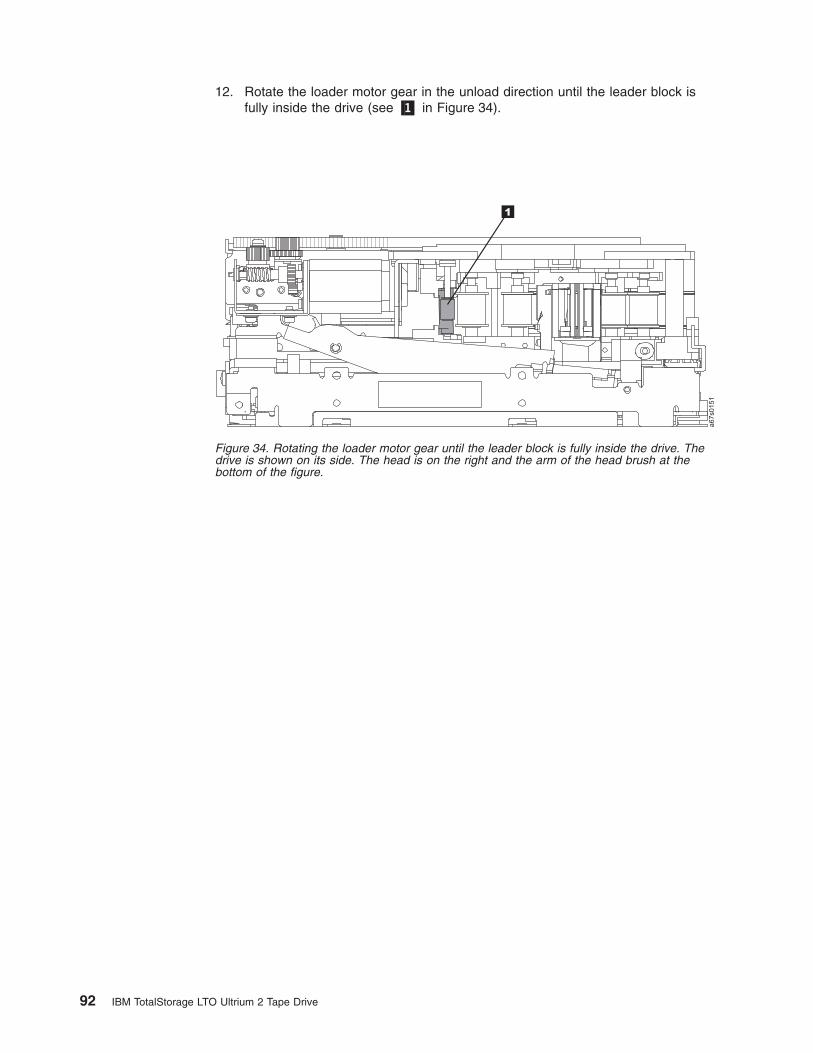
12. Rotate the loader motor gear in the unload direction until the leader block isfully inside the drive (see �1� in Figure 34).
Figure 34. Rotating the loader motor gear until the leader block is fully inside the drive. Thedrive is shown on its side. The head is on the right and the arm of the head brush at thebottom of the figure.
92 IBM TotalStorage LTO Ultrium 2 Tape Drive

13. Continue to rotate the loader motor gear counterclockwise. The leader blockretracts and occupies the opening to the drive (see �1� in Figure 35).
Figure 35. Rotating the loader motor gear so that the leader block retracts. The drive isshown on its side. The head is on the right and the arm of the head brush at the bottom ofthe figure.
Chapter 7. Servicing 93

14. Rotate the loader motor gear counterclockwise until you feel resistance andthe cartridge rises and ejects (see Figure 36).
15. Remove the tape cartridge. If the leader pin is not seated correctly in thecartridge, see “Repositioning or Reattaching a Leader Pin” on page 55.
16. Copy the data on the stuck tape cartridge to another cartridge. If appropriate,return the stuck tape cartridge for analysis in its original packaging or in thepackaging from its replacement.
17. Reassemble the tape drive by reversing the preceding steps.
18. To ensure that the drive operates properly, refer to page 36 and selectFunction Code 1 - Run Tape Drive Diagnostics.
If you need help with this procedure, contact your OEM Product ApplicationEngineer (PAE).
Figure 36. Rotating the loader motor gear until the cartridge ejects
94 IBM TotalStorage LTO Ultrium 2 Tape Drive

Appendix A. Tools and Supplies
Table 16 lists the tools and supplies that you can use with the IBM TotalStorageLTO Ultrium 2 Tape Drive. To order tools and supplies, contact your OEM ProductApplication Engineer (PAE) or visit the web at http://www.ibm.com/storage/lto.
Table 16. Tools and supplies for the IBM TotalStorage LTO Ultrium 2 Tape Drive
IBM Part Number Product Description
08L9129 Leader pin reattachment kit
- - 2.5-mm allen wrench (procure locally)
- - Plastic or blunt-end tweezers (procure locally)
08L9870 IBM TotalStorage LTO Ultrium 200 GB Data Cartridge
08L9124 IBM LTO Ultrium Cleaning Cartridge
35L2086 IBM TotalStorage Cleaning Cartridge (Ultrium LTO 2)
19P5897 IBM TotalStorage LTO Ultrium Data Cartridge bar codelabels
08L9267 IBM LTO Ultrium Cleaning Cartridge bar code labels
11P3847 Single port Fibre Channel wrap plug
19P5424 Fibre Channel duplex adapter
35L1782 SCSI Y-cable
19P0051 0.5-m (1.6-ft) SCSI cable
19P0052 5.0-m (16-ft) SCSI cable
19P0053 10-m (32-ft) SCSI cable
05H4651 25-m (82-ft) SCSI cable
19K1252 5-m (16-ft) fiber cable
11P3880 13-m (43-ft) fiber cable
19K1253 25-m (82-ft) fiber cable
11P3884 61-m (200-ft) fiber cable
11P3885 Custom-length fiber cable
© Copyright IBM Corp. 2002 95

96 IBM TotalStorage LTO Ultrium 2 Tape Drive

Appendix B. TapeAlert Flags
TapeAlert is a patented technology and standard of the American NationalStandards Institute (ANSI) that defines conditions and problems that areexperienced by tape drives. The technology enables a server to read TapeAlertflags from a tape drive through the SCSI, Fibre Channel, or Library/Drive Interface(LDI or RS-422 interface). The server reads the flags from Log Sense Page 0x2E.This appendix lists the TapeAlert flags that are supported by the IBM TotalStorageLTO Ultrium 2 Tape Drive.
TapeAlert Flags Supported by the Drive
TapeAlert Flags Supported by the IBM TotalStorage LTO Ultrium 2 Tape Drive
FlagNumber
FlagParameter
(in hex)Flag Description Action Required
3 03h Hard error Set for any unrecoverable read,write, or positioning error. (Thisflag is set in conjunction withflags 4, 5, or 6.)
See the Action Required columnfor Flag 4, 5, or 6 in this table.
4 04h Media Set for any unrecoverable read,write, or positioning error that isdue to a faulty tape cartridge.
Replace the tape cartridge.
5 05h Read failure Set for any unrecoverable readerror where isolation is uncertainand failure could be due to afaulty tape cartridge or to faultydrive hardware.
If Flag 4 is also set, the cartridgeis defective. Replace the tapecartridge. If Flag 4 is not set, seeerror code 6 in Table 15 onpage 67.
6 06h Write failure Set for any unrecoverable writeor positioning error whereisolation is uncertain and failurecould be due to a faulty tapecartridge or to faulty drivehardware.
If Flag 9 is also set, make surethat the write-protect switch isset so that data can be written tothe tape (see “Setting theWrite-Protect Switch” onpage 50). If Flag 4 is also set,the cartridge is defective.Replace the tape cartridge. IfFlag 4 is not set, see error code6 in Table 15 on page 67.
8 08h Not data grade Set when severe servo errorsoccur while loading a tapecartridge.
Replace the tape cartridge. If thiserror occurs with multiple tapes,see error code 6 in Table 15 onpage 67.
9 09h Write protect Set when the tape drive detectsthat the tape cartridge iswrite-protected.
Make sure that the cartridge’swrite-protect switch is set so thatthe tape drive can write data tothe tape (see “Setting theWrite-Protect Switch” onpage 50).
10 0Ah No removal Set when the tape drive receivesan UNLOAD command after theserver prevented the tapecartridge from being removed.
Refer to the documentation foryour server’s operating system.
© Copyright IBM Corp. 2002 97

TapeAlert Flags Supported by the IBM TotalStorage LTO Ultrium 2 Tape Drive
FlagNumber
FlagParameter
(in hex)Flag Description Action Required
11 0Bh Cleaning media Set when you load a cleaningcartridge into the drive.
No action required.
12 0Ch Unsupported format Set when you load anunsupported cartridge type intothe drive or when the cartridgeformat has been corrupted.
Use a supported tape cartridge.
15 0Fh Cartridge memorychip failure
Set when a cartridge memory(CM) failure is detected on theloaded tape cartridge.
Replace the cartridge. If thiserror occurs on multiple tapes,see error code 6 in Table 15 onpage 67.
16 10h Forced eject Set when you manually unloadthe tape cartridge while the drivewas reading or writing.
No action required.
18 12h Tape directorycorrupted in thecartridge memory
Set when the drive detects thatthe tape directory in the cartridgememory has been corrupted.
Re-read all data from the tape torebuild the tape directory.
20 14h Clean now Set when the tape drive detectsthat it needs cleaning.
Clean the tape drive. See“Cleaning the Drive Head” onpage 35.
21 15h Clean periodic Set when the drive detects that itneeds routine cleaning.
Clean the tape drive as soon aspossible. The drive can continueto operate, but you should cleanthe drive soon. See “Cleaningthe Drive Head” on page 35.
22 16h Expired clean Set when the tape drive detectsa cleaning cartridge that hasexpired.
Replace the cleaning cartridge.
23 17h Invalid cleaning tape Set when the drive expects acleaning cartridge and the loadedcartridge is not a cleaningcartridge.
Use a valid cleaning cartridge.
30 1Eh Hardware A Set when a hardware failureoccurs which requires that youreset the tape drive to recover.
If resetting the drive does notrecover the error, use the errorcode from the single-characterdisplay, library user interface, orSCSI drive sense data. SeeTable 15 on page 67.
31 1Fh Hardware B Set when the tape drive fails itsinternal self tests.
Use the error code on thesingle-character display, libraryuser interface, or SCSI drivesense data. See Table 15 onpage 67.
32 20h Interface Set when the tape drive detectsa problem with the SCSI, FibreChannel, or LDI (RS-422)interface.
Locate error code 8 or 9 inTable 15 on page 67.
33 21h Eject media Set when a failure occurs thatrequires you to unload thecartridge from the drive.
Unload and reload the tapecartridge.
98 IBM TotalStorage LTO Ultrium 2 Tape Drive

TapeAlert Flags Supported by the IBM TotalStorage LTO Ultrium 2 Tape Drive
FlagNumber
FlagParameter
(in hex)Flag Description Action Required
34 22h Download fail Set when an FMR image isunsuccessfully downloaded tothe tape drive via the SCSI orFibre Channel interface.
Ensure that it is the correctimage. Download the FMRimage again.
36 24h Drive temperature Set when the drive’s temperaturesensor indicates that the drive’stemperature is exceeding therecommended temperature of theenclosure (see Table 4 onpage 11).
See error code 1 in Table 15 onpage 67.
37 25h Drive voltage Set when the drive detects thatthe externally supplied voltagesare either approaching thespecified voltage limits or areoutside the voltage limits (seeTable 4 on page 11).
See error code 2 in Table 15 onpage 67.
39 27h Diagnostics required Set when the drive detects afailure that requires diagnosticsto isolate the problem.
See error code 6 in Table 15 onpage 67.
51 33h Tape directory invalidat unload
Set when the tape directory onthe tape cartridge that waspreviously unloaded is corrupted.The file-search performance isdegraded.
Rebuild the tape directory byreading all the data
52 34h Tape system areawrite failure
Set when the tape cartridge thatwas previously unloaded couldnot write its system areasuccessfully.
Copy the data to another tapecartridge, then discard the oldcartridge.
53 35h Tape system arearead failure
Set when the tape system areacould not be read successfully atload time.
Copy the data to another tapecartridge, then discard the oldcartridge.
Appendix B. TapeAlert Flags 99

100 IBM TotalStorage LTO Ultrium 2 Tape Drive

Notices
TrademarksThe following are trademarks of International Business Machines Corporation in theUnited States, or other countries, or both.
AIX iSeries SPAS/400 OS/400 TotalStorageEserver pSeries zSeriesIBM RS/6000
The following are U.S. trademarks of Hewlett-Packard Company, InternationalBusiness Machines Corporation, and Seagate Technology.
Linear Tape-Open UltriumLTO Ultrium LogoLTO Logo
Intel is a registered trademark of Intel Corporation in the United States, or othercountries, or both.
Microsoft, Windows, Windows NT, Windows 2000, and the Windows logo areregistered trademarks of Microsoft Corporation in the United States, or othercountries, or both.
Other company, product, or service names may be the trademarks or service marksof others.
© Copyright IBM Corp. 2002 101

Electronic Emission Notices
Special Considerations for Electromagnetic CompatibilityFor Class B electromagnetic emissions applications, the IBM TotalStorage LTOUltrium 2 Tape Drive requires that you install it with a Class B front bezel. ContactIBM for ordering information or for assistance with bezel design requirements forClass B environments. System integrators should refer to the product’s functionalspecification for additional information.
Models T400 and T400F of the IBM TotalStorage LTO Ultrium 2 Tape Drive havebeen found to satisfy electromagnetic compatibility (EMC) requirements when theyare installed in a suitably designed enclosure. Due to the high-performance andhigh-frequency operation of these drives, your enclosure must have sufficient EMCshielding and filtering for the intended product class (A or B). It is themanufacturer’s responsibility to ensure compliance to the required EMC standardsby using appropriate testing and certification.
IBM TotalStorage LTO Ultrium 2 Tape Drive Models T400 and T400FThe following statement applies to this product. The statement for other productsthat are intended for use with this product will appear in their accompanyingmanuals.
Federal Communications Commission (FCC) Class B StatementNote: This equipment has been tested and found to comply with the limits for aClass B digital device, pursuant to Part 15 of the FCC Rules. These limits aredesigned to provide reasonable protection against harmful interference in aresidential installation. This equipment generates, uses, and can radiate radiofrequency energy and, if not installed and used in accordance with the instructions,may cause harmful interference to radio communications. However, there is noguarantee that interference will not occur in a particular installation. If thisequipment does cause harmful interference to radio or television reception, whichcan be determined by turning the equipment off and on, the user is encouraged totry to correct the interference by one or more of the following measures:
v Reorient or relocate the receiving antenna.
v Increase the separation between the equipment and receiver.
v Connect the equipment into an outlet on a circuit different from that to which thereceiver is connected.
v Consult an IBM authorized dealer or service representative for help.
IBM is not responsible for any radio or television interference caused byunauthorized changes or modifications to this equipment. Unauthorized changes ormodifications could void the user’s authority to operate the equipment.
This device complies with Part 15 of the FCC Rules. Operation is subject to thefollowing two conditions: (1) this device may not cause harmful interference, and (2)this device must accept any interference received, including interference that maycause undesired operation.
Industry Canada Class B Emission Compliance StatementThis Class B digital apparatus complies with Canadian ICES-003.
Avis de conformité à la réglementation d’Industrie CanadaCet appareil numérique de la classe B est conform à la norme NMB-003 duCanada.
102 IBM TotalStorage LTO Ultrium 2 Tape Drive
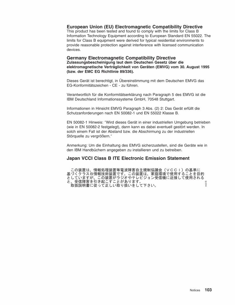
European Union (EU) Electromagnetic Compatibility DirectiveThis product has been tested and found to comply with the limits for Class BInformation Technology Equipment according to European Standard EN 55022. Thelimits for Class B equipment were derived for typical residential environments toprovide reasonable protection against interference with licensed communicationdevices.
Germany Electromagnetic Compatibility DirectiveZulassungsbescheinigung laut dem Deutschen Gesetz über dieelektromagnetische Verträglichkeit von Geräten (EMVG) vom 30. August 1995(bzw. der EMC EG Richtlinie 89/336).
Dieses Gerät ist berechtigt, in Übereinstimmung mit dem Deutschen EMVG dasEG-Konformitätszeichen - CE - zu führen.
Verantwortlich für die Konformitätserklärung nach Paragraph 5 des EMVG ist dieIBM Deutschland Informationssysteme GmbH, 70548 Stuttgart.
Informationen in Hinsicht EMVG Paragraph 3 Abs. (2) 2: Das Gerät erfüllt dieSchutzanforderungen nach EN 50082-1 und EN 55022 Klasse B.
EN 50082-1 Hinweis: ″Wird dieses Gerät in einer industriellen Umgebung betrieben(wie in EN 50082-2 festgelegt), dann kann es dabei eventuell gestört werden. Insolch einem Fall ist der Abstand bzw. die Abschirmung zu der industriellenStörquelle zu vergrößern.″
Anmerkung: Um die Einhaltung des EMVG sicherzustellen, sind die Geräte wie inden IBM Handbüchern angegeben zu installieren und zu betreiben.
Japan VCCI Class B ITE Electronic Emission Statement
vcci-b
Notices 103

Getting HelpIf you need assistance while installing or operating your IBM TotalStorage LTOUltrium 2 Tape Drive, contact your OEM Product Application Engineer (PAE).
WarrantyThe warranty for this product is negotiated on a per-customer basis.
104 IBM TotalStorage LTO Ultrium 2 Tape Drive

Glossary
This glossary defines the special terms,abbreviations, and acronyms that are used in thispublication.
Numbers and Symbols2:1 compression. The relationship between thequantity of data that can be stored with compression ascompared to the quantity of data that can be storedwithout compression. In 2:1 compression, twice asmuch data can be stored with compression as can bestored without compression.
µs. Abbreviation for microsecond or one millionth of asecond (.000001 s).
AA. See ampere.
acclimation time. Pertaining to the Ultrium 2 TapeDrive, the amount of time that is needed for the drive toadjust to change in temperature, altitude, climate, orenvironment.
active. The condition that the SCSI bus is in when aserver is trying to use one or more devices on the bus.
adapter. See adapter card.
adapter card. A circuit board that adds function to acomputer.
AL_PA. See Arbitrated Loop Physical Address.
amp. See ampere.
ampere (A, amp). A unit of measure for electriccurrent that is equivalent to a flow of one coulomb persecond, or equivalent to the current produced by onevolt applied across a resistance of one ohm.
American National Standards Institute. A private,non-profit organization that gathers and disseminatesinformation about standards and conformity issues thataffect the business, government, and people of theUnited States.
ANSI. See American National Standards Institute.
Arbitrated Loop Physical Address (AL_PA). An 8-bitvalue that identifies a device in an arbitrated loop. AllFibre Channel ports communicate by using AL_PAs.
autosense data. Sent by the drive to the server,sense data that automatically accompanies a CheckCondition in response to an error. The server does notneed to send a REQUEST SENSE command to get the
sense data. Autosense data is available only in theFibre Channel version of the Ultrium 2 Tape Drive(Model T400F).
Bbackhitch. During tape movement (reading or writing),the condition that occurs when the tape drive must stopthe tape, reverse it, and restart tape motion due tocertain events. A backhitch usually occurs when theserver’s net (compressed) data rate is less than thedrive’s data rate.
backreflection. Pertaining to instances where light islaunched into an optical fiber in a forward direction, thelight that is returned to the launch point in the reversedirection.
backups. The short-term retention of records used forrestoring essential business and server files when vitaldata has been lost because of program or server errorsor malfunctions.
backward compatible. Capable of being used with aprevious product that was designed for a similarpurpose. For example, a tape cartridge that is designedto be used with a modern tape drive but can also beused with certain older tape drives. Synonymous withdownward compatible.
bar code. A code that represents characters by sets ofparallel bars of varying thickness and separation. Thebars are read optically by transverse scanning.
bar code label. A slip of paper bearing a bar code andhaving an adhesive backing. The bar code label mustbe affixed to a tape cartridge to enable the library toidentify the cartridge and its volume serial number.
bezel. The removable frame that fits over the front ofthe Ultrium 2 Tape Drive.
bit. The smallest unit of data in a computer. A bit(short for binary digit) has a single binary value (either 0or 1). Computers store data and execute instructions inbit multiples called bytes. In most computer systems,there are eight bits in a byte.
burst data transfer rate. The maximum speed atwhich data is transferred.
bus. See SCSI bus.
byte. A string that consists of a certain number of bits(usually 8) which are treated as a unit and represent acharacter. A byte is a fundamental unit of data.
© Copyright IBM Corp. 2002 105

CC. See Celsius.
capacity. The amount of data that can be containedon storage media and expressed in bytes.
cartridge. See tape cartridge.
cartridge door. On a tape cartridge, the hinged barrierthat can be opened to access, or closed to protect, themagnetic tape within the cartridge.
cartridge manual rewind tool. A device that can befitted into the reel of a cartridge and used to rewind tapeinto or out of the cartridge.
cartridge memory. See LTO cartridge memory.
Celsius. Having a thermometric scale on which theinterval between the freezing point and the boiling pointof water is divided into 100 degrees, with 0°representing the freezing point and 100° representingthe boiling point.
channel calibration. A feature of the Ultrium 2 TapeDrive by which it automatically customizes eachread/write data channel to compensate for variations insuch things as the recording channel’s transfer function,the media, and characteristics of the drive head.Channel calibration optimizes system performance.
circuit board. A thin sheet on which chips and otherelectronic components are placed. Computers consist ofone or more boards, often called cards or adapters.
cleaning cartridge. A tape cartridge that is used toclean the heads of a tape drive. Contrast with datacartridge.
clockwise. In the direction that the hands of a clockrotate, as viewed from the front.
command time-out. Following the issuance of acommand, a period of time during which it is determinedthat there is a bad connection between the server andthe drive.
compression. The process of eliminating gaps, emptyfields, redundancies, and unnecessary data to shortenthe length of records or blocks.
configure. To describe to a server the devices,optional features, and programs installed on the system.
contiguous. Touching along a boundary or at a point.
core. The light-conducting central portion of an opticalfiber. The core is composed of material that has ahigher index of refraction than the cladding (the materialthat surrounds the core).
counterclockwise. In a direction opposite to that inwhich the hands of a clock rotate, as viewed from thefront.
current. The quantity of charge per unit of time.Current is measured in amperes.
cycle power. To apply and remove electrical power toa device within a short time span.
Ddata. Any representations such as characters oranalog quantities to which meaning is, or might be,assigned.
data cartridge. A tape cartridge that is dedicated tostoring data. Contrast with cleaning cartridge.
data compression. See compression.
data transfer rate. The average number of bits,characters, or blocks per unit of time that pass betweencorresponding equipment in a data transmission system.The rate is expressed in bits, characters, or blocks persecond, minute, or hour.
dc. Direct current.
degauss. To make a magnetic tape nonmagnetic byexposing the tape to electrical coils which carry currentsthat neutralize the magnetism of the tape.
device. Any hardware component or peripheral, suchas a tape drive or tape library, that can receive andsend data.
device driver. A file that contains the firmware that isneeded to use an attached device.
diagnostic. A software program that is designed torecognize, locate, and explain faults in equipment orerrors in programs.
diagnostic cartridge. A tape cartridge that enablesthe detection and isolation of errors in programs andfaults in equipment.
direct current (dc). An electric current flowing in onedirection only and substantially constant in value.
director-class switch. A high-end switch that includessuch qualities as fault tolerance, high throughput, highreliability, port density, and so forth.
drive. See IBM TotalStorage LTO Ultrium 2 TapeDrive.
drive dump. The recording, at a particular instant, ofthe contents of all or part of one storage device intoanother storage device, usually as a safeguard againstfaults or errors, or in connection with debugging.
106 IBM TotalStorage LTO Ultrium 2 Tape Drive

drive head. The component that records an electricalsignal onto magnetic tape, or reads a signal from tapeinto an electrical signal.
drive sense data. See SCSI drive sense data.
dump. See drive dump.
duplex. See duplex transmission.
duplex adapter. A mechanism that allows a device tosend and receive communication at the same time.
duplex transmission. Transmission in both directions,either one direction at a time (half-duplex) or bothdirections simultaneously (full-duplex).
Eeject. To remove or force out from within.
electronic mail. Correspondence in the form ofmessages transmitted between user terminals over acomputer network.
e-mail. See electronic mail.
enclosure. A device, such as a desktop unit, tapecartridge autoloader, or tape library, into which you caninstall the Ultrium 2 Tape Drive.
error log. Maintained by the Ultrium 2 Tape Drive, alist that contains the ten most recent error codes. Thecodes identify errors that pertain to the drive.
Ffabric. A Fibre Channel entity which interconnects andfacilitates logins of N_ports that attach to it. The fabric isresponsible for routing frames between source anddestination N_ports by using address information in theframe header. A fabric can be as simple as apoint-to-point channel between two N-ports, or ascomplex as a frame-routing switch that provides multipleand redundant internal pathways within the fabricbetween F_ports.
fan shroud. The wire mesh enclosure around the fanthat holds it in place and prevents direct access. Theshroud mounts the fan assembly to the Ultrium 2 TapeDrive. generic FC reference to an N_port or an F_port.
FC-AL. See Fibre Channel-Arbitrated Loop.
FC port. See Fibre Channel port.
feature switch. Located under the Ultrium 2 TapeDrive, a bank of eight micro switches that can bemanually toggled on or off to activate or deactivatedifferent characteristics of the drive.
fiber optic cable. The medium by which light istransmitted through fibers or thin rods of glass or someother transparent material of high refractive index.
fiber optics. A branch of optics dealing with thetransmission of light through fibers or thin rods of glassor some other transparent material of high refractiveindex.
Fibre Channel. A 100-MB-per-second, full-duplex,serial communications technology that is capable ofinterconnecting Ultrium 2 Tape Drives and servers whichare separated by as much as 11 kilometers (7 miles).Fibre Channel technology combines features of theinput/output (I/O) and networking interfaces.
Fibre Channel address. For a tape drive that uses aFibre Channel interface, an identifier (such as an AL_PAor Loop ID) that enables other device ports tocommunicate with that drive. A Fibre Channel drive hasa 3-byte address. The switch assigns the upper 2 bytesof the address. If no switch is attached, the 2 bytesequal 0. The lower byte assignment (which is theAL_PA) varies, depending on whether hard or softaddressing is used.
Fibre Channel-Arbitrated Loop (FC-AL) topology. Aserial data-transfer architecture and standard governedby ANSI. FC-AL is designed for mass storage devicesand other peripheral devices that require highbandwidth. By using optical fiber to connect devices,FC-AL supports full-duplex data transfer rates of100MBps. An FC-AL topology is compatible with a SCSIinterface for high-performance storage systems.
Fibre Channel cable. The cable that connects a FibreChannel tape drive to another device. The conductiveelement within the cable is constructed of either copperwires or optical fibers. Generally, copper wires are usedfor short distances (up to 30 meters or 98 feet); opticalfibers are used for longer distances. Fiber-optic cablingis referred to by mode or the frequencies of light wavesthat are carried by a particular cable type. Multimodefiber cables are generally used for distances up to 500meters (1640 feet) and with short-wave (780nanometer) laser light. Single-mode fiber cables areused for distances greater than 500 m (1640 feet) andwith long-wave (1300 nanometer) laser light.
Fibre Channel configuration/status connector.Located at the rear of a Fibre Channel drive, theconnector that allows you to optionally change thedrive’s link services (for example, its speed and type oftopology).
Fibre Channel interface. The hardware or softwarethat links differing Fibre Channel systems, programs ordevices.
Fibre Channel port. A generic Fibre Channelreference to an N_port or an F_port.
Glossary 107

Fibre Channel protocol. An evolving ANSIinterconnection standard for high-speed data transferamong computers and storage devices defined by theFibre Channel Protocol (FCP). At the physical level,data is transmitted serially over pairs of point-to-pointlinks between FC ports. With appropriate components,data can be transferred at 100 MB/sec up over adistance of 10 km between FC ports. The ports can beconfigured in ring and switched interconnect topologieswhich allow each port to exchange data with any otherport that is part of the same fabric.
Fibre Channel wrap test. A diagnostic that causes theUltrium 2 Tape Drive to perform a check of the FibreChannel circuitry from and to the drive’s Fibre Channelconnector or the fiber cable.
field microcode replacement tape. A tape cartridgethat contains new or revised firmware (microcode) forthe Ultrium 2 Tape Drive.
file. A named set of records that are stored orprocessed as a unit.
filemark. Located on the magnetic tape within a tapecartridge, a recorded element that typically marks theorganizational boundaries in a serial file structure (suchas directory boundaries) and that is requested to bewritten or read by the server.
firmware. The proprietary code that is usuallydelivered as part of an operating system. Firmware ismore efficient than software that is loaded from analterable medium, and is more adaptable to changethan pure hardware circuitry. An example of firmware isthe Basic Input/Output System (BIOS) in read-onlymemory (ROM) on a PC motherboard.
FMR tape. See field microcode replacement tape.
foot. A unit of length comprising 12 inches.
GGb. See gigabit.
GB. See gigabyte.
Generation 1. The informal name for the IBM UltriumInternal Tape Drive, which is the predecessor of theUltrium 2 Tape Drive (Generation 2). The Generation 1drive has a native storage capacity of up to 100 GB percartridge and a native sustained data transfer rate of 15MB per second.
Generation 2. The informal name for the Ultrium 2Tape Drive, which is the second-generation version ofthe IBM Ultrium Internal Tape Drive (Generation 1). TheGeneration 2 drive has a native storage capacity of upto 200 GB per cartridge and a native sustained datatransfer rate of 35 MB per second.
gigabit (Gb). 1 000 000 000 bits. 1 Gb equals 100 MB.
gigabyte (GB). 1 000 000 000 bytes.
ground. An object that makes an electrical connectionwith the earth.
Hhard addressing. Pertaining to the Fibre Channeldrive (Model T400F), a method that identifies the drive’sLID and, consequently, its AL_PA (the AL_PA enablesthe drive to communicate with other devices).
hardware. The physical equipment or devices thatform a computer.
head. See drive head.
Head Resistance Measurements test. Part of theTest Head diagnostic, a procedure that determineswhether the tape drive’s head works correctly. The testmeasures the head’s ability to withstand cracks andother defects.
host. The controlling or highest-level system in a datacommunication configuration. Synonymous with server.
hot-pluggable. Pertaining to the Ultrium 2 Tape Drive,the ability to remove the drive from an enclosure whilethe enclosure is powered-on.
hub. A communications device to which nodes on amulti-point bus or loop are physically connected. Hubsare commonly used in Fibre Channel networks toimprove the manageability of physical cables. Theymaintain the logical loop topology of the network ofwhich they are a part, while creating a “hub and spoke”physical star layout. Unlike switches, hubs do notaggregate bandwidth. They typically support the additionor removal of nodes from the bus while it is operating.
IIBM TotalStorage LTO Ultrium 2 Tape Drive. Adata-storage device that controls the movement of themagnetic tape in an IBM LTO Ultrium Tape Cartridge.The drive houses the mechanism (drive head) thatreads and writes data to the tape. The drive is the firstof four drives planned for the Ultrium format. Its nativedata capacity is 100 GB per cartridge; with 2:1compression, its capacity is up to 200 GB.
ID. Identifier.
in. See inch.
inch. A unit of length equal to 1/36 yard or 25.4 mm.
initiator. In SCSI terms, a SCSI device that requestsan I/O process to be performed by another SCSI device(a target). In many cases, an initiator can also be atarget.
108 IBM TotalStorage LTO Ultrium 2 Tape Drive

input/output (I/O). Data that is provided to a computeror data that results from computer processing.
insertion guide. On the surface of the IBM LTOUltrium Tape Cartridge, a large, notched area thatprevents you from inserting the cartridge incorrectly.
install. (1) To set up for use or service. (2) The act ofadding a product, feature, or function to a server ordevice either by a singular change or by the addition ofmultiple components or devices.
Internet. The worldwide collection of interconnectednetworks that use the Internet suite of protocols andpermit public access.
interposer. An adapter-like device that allows aconnector of one size and style to connect to a matingconnector of a different size and style. Data provided tothe computer or data resulting from computerprocessing.
I/O. See input/output.
JJ2 connector. Located at the rear of the Ultrium 2Tape Drive, the connector for the LDI (or RS-422)interface.
J33 connector. Located at the rear of the Ultrium 2Tape Drive, a single connector that contains theconnections for the SCSI signals and grounds, SCSI ID,SCSI bus termination, and drive power.
jumper. (1) A tiny connector that fits over a pair ofprotruding pins in a connector. A jumper can be movedto change electrical connectors. When in place, thejumper connects the pins electrically. (2) To place ajumper on a connector pin.
Llabel. A slip of paper with an adhesive backing thatcan be written on and affixed to a tape cartridge as ameans of identification or description.
label area. On the LTO Ultrium Tape Cartridge, arecessed area next to the write-protect switch where abar code label must be affixed.
LAN. See local area network.
LDI. See Library/Drive Interface.
leader-pin block. Located within the Ultrium 2 TapeDrive, the part that engages the steel pin which isattached to the tape in an LTO Ultrium Tape Cartridge.Once engaged, the leader-pin block pulls the tape fromthe cartridge into the drive.
leader pin. On the LTO Ultrium Tape Cartridge, asmall metal column that is attached to the end of themagnetic tape. During tape processing the leader pin isgrasped by a threading mechanism, which pulls the pinand the tape out of the cartridge, across the drive head,and onto a takeup reel. The head can then read or writedata from or to the tape.
LED. See light-emitting diode.
Library/Drive Interface. An electrical interfacestandard that is approved by the Electronic IndustriesAssociation (EIA) for connecting serial devices.
Library/Drive Interface (LDI) connector. Located atthe rear of the Ultrium 2 Tape Drive, the connector towhich the internal LDI cable of an enclosure connects.The connection enables serial devices to communicatewith the drive.
LID. See loop identifier.
LID/status connector. See loop identifier (LID)/statusconnector.
link services. The speed and topology of your FibreChannel drive. If you choose not to alter the linkservices, the drive defaults to a negotiated speed andoperation in an FC-AL topology with a direct connectionto the server.
LIP. See loop initialization protocol.
light-emitting diode (LED). A semiconductor diodethat emits light when subjected to an applied voltageand that is used in an electronic display.
Linear Tape-Open (LTO). A type of tape storagetechnology developed by the IBM Corporation,Hewlett-Packard, and Seagate. LTO technology is an“open format” technology, which means that its usershave multiple sources of product and media. The “open”nature of LTO technology enables compatibility betweendifferent vendors’ offerings by ensuring that vendorscomply with verification standards.
load. Following the insertion of a tape cartridge intothe tape load compartment, the act of positioning thetape (performed by the tape drive) for reading or writingby the drive’s head.
load and unload cycle. The act of inserting acartridge into a tape drive, loading the tape to loadpoint, rewinding the tape into the cartridge, and ejectingthe cartridge from the drive.
local area network (LAN). A computer network that islocated on a user’s premises within a limitedgeographical area. The network consists of a set ofdevices that are connected to one another forcommunication and that can be connected to a largernetwork. Communications are limited to a
Glossary 109
moderate-sized geographic area (1 to 10 km) such as asingle office building, warehouse, or campus.
log sense data. See SCSI log sense data.
loop. (1) A series of instructions that is repeated until aterminating condition is reached. (2) To connect so as tocomplete a loop.
loop ID. See loop identifier.
loop identifier (LID). In a Fibre Channel topology, theidentifier that a device assigns to an Ultrium 2 TapeDrive. An operator uses the LID to set the AL_PA.
loop identifier (LID)/status connector. Located onthe Model T400F, the connector that is used to set theLoop ID and provide status about the loop.
loop initialization protocol (LIP). A method by whicha device in a Fibre Channel Arbitrated Loop acquires itsAL_PA.
loss. In fiber optics technology, the amount of asignal’s power (expressed in dB) that is lost inconnectors, splices, or fiber defects.
Low Voltage Differential (LVD). A low-noise,low-power, and low-amplitude electrical signaling systemthat enables data communication between a supportedserver and the Ultrium 2 Tape Drive. LVD signaling usestwo wires to drive one signal over copper wire. The useof wire pairs reduces electrical noise and crosstalk.
L_port. Located on the Ultrium 2 Tape Drive, the FibreChannel portal that facilitates communication only in anFC-AL topology. An L_port also allows connection toFL_ports and NL_ports.
LTO. See Linear Tape-Open.
LTO cartridge memory (LTO-CM). Within each LTOUltrium Data Cartridge, an embedded electronics andinterface module that can store and retrieve acartridge’s historical usage and other information.
LTO-CM. See LTO cartridge memory.
LTO-DC. See LTO Data Compression.
LTO Data Compression (LTO-DC). A method thatcompresses a server’s data before the drive writes it totape. LTO-DC detects but does not recompress or testrecord boundaries and file markers (which are encodedas control symbols). It also allows switching betweencompression and no compression within the datastream, which prevents data from expanding when thedrive compresses random or encrypted data.
LVD. See Low Voltage Differential.
Mm. See meter.
magnetic tape. A tape with a magnetizable surfacelayer on which data can be stored by magneticrecording.
maintenance mode. The state of operation in whichthe Ultrium 2 Tape Drive must be before it can rundiagnostics, verify write and read operations, verify asuspect tape cartridge, update its own firmware, andperform other diagnostic and maintenance functions.
MB. See megabyte.
media. The plural of medium.
media capacity. See capacity.
medium. A physical material in or on which data maybe represented, such as magnetic tape.
megabyte (MB). 1 000 000 bytes.
metal particle tape. In the LTO Ultrium TapeCartridge, tape that uses very small, pure metalparticles (rather than oxide coatings) in the magneticlayer.
meter. In the Metric System, the basic unit of length;equal to approximately 39.37 inches.
micrometer. One millionth of a meter (.000001 m).Synonymous with micron. Abbreviated as µm.
micron. One millionth of a meter (.000001 m).Synonymous with micrometer. Abbreviated as µm.
microsecond. One millionth of a second (.000001 s).Abbreviated as µs.
millimeter (mm). One thousandth of a meter (.001 m).
millisecond (ms). One thousandth of a second (.001s).
mm. See millimeter.
Model T400. The version of the IBM TotalStorage LTOUltrium 2 Tape Drive that uses the SCSI interface.
Model T400F. The version of the IBM TotalStorageLTO Ultrium 2 Tape Drive that uses the Fibre Channelinterface.
ms. See millisecond.
multimode fiber. An optical fiber that has a core thatis large enough to propagate more than oneelectromagnetic wave of light. The typical diameter is62.5 micrometers.
110 IBM TotalStorage LTO Ultrium 2 Tape Drive
NN/A. Not applicable.
native storage capacity. The amount of data that canbe stored without compression on a tape cartridge.
native sustained data transfer rate. See datatransfer rate.
negotiated speed. Defined by Fibre ChannelStandards, the algorithm that ensures the highest speedthat is supported by both the Ultrium 2 Tape Drive andthe port to which it attaches. This negotiation occurs atpower up and whenever a catastrophic link eventoccurs, such as a cable pull that exceeds the timeoutsthat are specified in the Standards. The speed isnegotiated when the first possibility of a new connection(for example, a fiber cable) is established, and ismaintained until the Fibre Channel connection isterminated. The speed is not renegotiated when a newdevice is attached to a loop.
network. A configuration of data processing devicesand software that is connected for informationinterchange.
network server. In a local area network, a personalcomputer that provides access to files for all of theworkstations in the network.
node. In Fibre Channel technology, a communicatingdevice.
N_port. Located on the Ultrium 2 Tape Drive, the FibreChannel portal that facilitates communication only in apoint-to-point topology. An N_port also allowsconnection to F_ports.
NL_port. Located on the Ultrium 2 Tape Drive, theFibre Channel portal that facilitates communication onlyin a point-to-point topology (by acting as an N_port). Ifthe connection fails, the port attempts to connect in anFC-AL topology (by acting as an L_port).
ntutil. Created by IBM, a utility program for LTOdevices that connect to Windows NT and Windows2000. ntutil provides problem determination forhardware or connections, assists with device andmedium changer recognition, forces dumps, loads newfirmware, sends and receives SCSI commands to andfrom the hardware, and obtains SCSI sense data to usein resolving errors.
Ooersted. The unit of magnetic field strength in theunrationalized centimeter-gram-second (cgs)electromagnetic system. The oersted is the magneticfield strength in the interior of an elongated, uniformly
wound solenoid that is excited with a linear currentdensity in its winding of one abamper per 4πcentimeters of axial length.
offline. The operating condition that the Ultrium 2 TapeDrive is in when the server’s applications cannot interactwith it.
online. The operating condition that the Ultrium 2 TapeDrive is in when the server’s applications can interactwith it.
Open Systems. Computer systems whose standardsare not proprietary.
operating environment. The temperature, relativehumidity rate, and wet bulb temperature of the room inwhich the Ultrium 2 Tape Drive routinely conductsprocessing.
operating system. The master computer controlprogram that translates the user’s commands andallows software application programs to interact with thecomputer’s hardware.
optical transceiver. A device that both transmits andreceives analog or digital signals over a light source.
Ppanic reset. The act of pressing and holding theunload button for 10 seconds to force a reset of anonresponsive drive.
parity. The state of being even-numbered orodd-numbered. A parity bit is a binary number that isadded to a group of binary numbers to make the sum ofthat group always odd (odd parity) or even (even parity).
parity error. A transmission error that occurs when thereceived data does not have the parity that is expectedby the receiving system. This usually occurs when thesending and receiving systems have different paritysettings.
point-to-point connection. Pertaining to datatransmission between two locations without the use ofany intermediate display station or computer.
port. (1) A system or network access point for dataentry or exit. (2) A connector on a device to whichcables for other devices such as display stations andprinters are attached. (3) The representation of aphysical connection to hardware. A port is sometimesreferred to as an adapter; however, there can be morethan one port on an adapter.
power connector. Located at the rear of the Ultrium 2Tape Drive, the connector to which the internal powercable of an enclosure connects.
power cord. A cable that connects a device to asource of electrical power.
Glossary 111

power-off. To remove electrical power from a device.
power-on, powered-on. (1) To apply electrical powerto a device. (2) The state of a device when power hasbeen applied to it.
private device. A device that is attached directly to aserver and is not connected to a fabric or switch. Aprivate device can be part of an arbitrated loop topologyor point-to-point topology.
protocol. The meanings of, and the sequencing rulesfor, requests and responses that are used to manage anetwork, transfer data, and synchronize the states ofnetwork components.
public device. A device that is attached to a fabric orswitch, and can communicate to that fabric or switch. Apublic device can be part of an arbitrated loop topologyor point-to-point topology.
Qquiesce. To put a device into a temporarily inactive orinhibited state, but not remove it from the server.
Rread. To acquire or interpret data from a storagedevice, from a data medium, or from another source.
reboot. To reinitialize the execution of a program byrepeating the initial program load (IPL) operation.
record. The smallest distinct set of data bytes that issupplied from a server for processing and recording bya tape drive, and the smallest distinct set of data to beread from tape, reprocessed, and made available to aserver by a tape drive.
record boundaries. The fixed limits of a record.
relative humidity. The ratio of the amount of watervapor actually present in the air to the greatest amountpossible at the same temperature.
repeater. A device that regenerates signals to extendthe range of transmission between data stations or tointerconnect two branches. A repeater is a node of alocal area network.
reset. To return a device or circuit to a clear state.
LDI wrap plug. A connector mechanism that connectsto an LDI port for the purpose of testing the Ultrium 2Tape Drive’s circuitry for the LDI interface.
LDI wrap test. A diagnostic that can be run on theUltrium 2 Tape Drive to determine whether the circuitryfunctions properly to and from the LDI connector.
Ss. See second.
SAN. See Storage Area Network.
SAN Data Gateway. A device that provides FibreChannel attachment between Open Systems serversand SCSI disk and tape storage systems.
SC. See subscription channel connector.
scratch cartridge. A data cartridge that contains nouseful data, but can be written to with new data.
SCSI. See Small Computer Systems Interface.
SCSI bus. (1) A collection of wires through which datais transmitted from one part of a computer to another.(2) A generic term that refers to the complete set ofsignals that define the activity of the Small ComputerSystems Interface (SCSI).
SCSI connector. Located at the rear of the Ultrium 2Tape Drive, the connector that facilitates commands toand from the server, and to which the internal SCSIcable of an enclosure connects.
SCSI device. Anything that can connect into the SCSIbus and actively participate in bus activity.
SCSI drive sense data. In response to inquiry fromthe server about an error condition, a packet of SCSIsense bytes that contains information about the errorand that is sent back to the server by the drive.
SCSI ID. The unique address (from 1 to 15) that youassign to an Ultrium 2 Tape Drive that uses a SCSIinterface (Model T400).
SCSI ID connector. Located at the rear of the Ultrium2 Tape Drive, the connector that enables the drive’sSCSI address to be set. Addresses are determined bythe placement of jumpers on the pins.
SCSI interface. See Small Computer SystemsInterface.
SCSI protocol. A set of rules that control thecommunication and transfer of data between two ormore SCSI devices or systems in a communicationsnetwork.
SCSI ID switch. Located on an enclosure thatcontains a Ultrium 2 Tape Drive, a mechanism thatconnects to the drive and allows you to change thedrive’s SCSI ID without using jumpers.
SCSI log sense data. In response to inquiry from theserver about the Ultrium 2 Tape Drive’s error logs andcounters, a packet of SCSI sense bytes which containsthat information and which is sent back to the server by
112 IBM TotalStorage LTO Ultrium 2 Tape Drive

the drive. Log sense data is used to diagnose problems,especially if the problems are intermittent.
SCSI wrap plug. A connector mechanism thatconnects to a SCSI port for the purpose of testing theUltrium 2 Tape Drive’s circuitry for the SCSI interface.
SCSI wrap test. A diagnostic that can be run on theUltrium 2 Tape Drive to determine whether the circuitryfunctions properly to and from the SCSI connector.
second. One sixtieth of a minute.
selection time-out. Following the selection of anoption (for example, a data transfer), the period of timeduring which it is determined that there is a badconnection between the server and the drive.
sense data. Data that describes an I/O error. Sensedata is presented to a server in response to a SenseI/O command.
serial interface. An interface that sequentially orconsecutively executes two or more operations in asingle device, such as an arithmetic and logic operation.
server. A functional unit that provides services to oneor more clients over a network. Examples include a fileserver, a print server, or a mail server. The IBMEserver pSeries, IBM Eserver iSeries, HP, and Sunare servers. Synonymous with host.
ship group. The group of supplies, cords, ordocumentation that is shipped with the Ultrium 2 TapeDrive.
shipping environment. The temperature, relativehumidity rate, and wet bulb temperature of theenvironment to which the Ultrium 2 Tape Drive isexposed when it is transferred from one location toanother.
short-wave cable. In Fibre Channel technology, alaser cable that uses a wavelength of 780 nanometersand is only compatible with multimode fiber.
single-character display. Located at the front of theUltrium 2 Tape Drive, an LED that presents analphabetical or numeric code which represents adiagnostic or maintenance function, error condition, orinformational message.
sleep mode. A power-management function thatcauses the Ultrium 2 Tape Drive’s electronics toautomatically enter a low-power mode by which toconserve energy.
Small Computer Systems Interface (SCSI). Astandard used by computer manufacturers for attachingperipheral devices (such as tape drives, hard disks,CD-ROM players, printers, and scanners) to computers(servers). Pronounced ″scuzzy.″ Variations of the SCSIinterface provide for faster data transmission rates than
standard serial and parallel ports (up to 160 megabytesper second). The variations include:
v Fast/Wide SCSI: Uses a 16-bit bus, and supportsdata rates of up to 20 MBps.
v SCSI-1: Uses an 8-bit bus, and supports data ratesof 4 MBps.
v SCSI-2: Same as SCSI-1, but uses a 50-pinconnector instead of a 25-pin connector, andsupports multiple devices.
v Ultra SCSI: Uses an 8- or 16-bit bus, and supportsdata rates of 20 or 40 MBps.
v Ultra2 SCSI: Uses an 8- or 16-bit bus and supportsdata rates of 40 or 80 MBps.
v Ultra3 SCSI: Uses a 16-bit bus and supports datarates of 80 or 160 MBps.
v Ultra160 SCSI: Uses a 16-bit bus and supports datarates of 160 MBps.
soft addressing. Pertaining to the Fibre Channel drive(Model T400F), a method that enables the drive todynamically arbitrate its AL_PA with other Fibre Channeldevices on the loop. The AL_PA enables the drive tocommunicate with other devices.
software. Programs, procedures, rules, and anyassociated documentation pertaining to the operation ofa computer system.
speed matching. A technique used by the Ultrium 2Tape Drive to dynamically adjust its native(uncompressed) data rate to the slower data rate of aserver. Speed matching improves system performanceand reduces backhitch.
status light. Located at the front of the Ultrium 2 TapeDrive, an LED that can be green or amber, and (whenlit) solid or flashing. The condition of the light representsthe state of the drive.
Storage Area Network (SAN). A high-speedsubnetwork of shared storage devices. A SAN’sarchitecture makes all storage devices available to allservers on a LAN or WAN. As more storage devices areadded to a SAN, they too will be accessible from anyserver in the larger network. Because stored data doesnot reside directly on any of a network’s servers, serverpower is used for business applications, and networkcapacity is released to the end user.
storage environment. The temperature, relativehumidity rate, and wet bulb temperature of theenvironment in which the Ultrium 2 Tape Drive isnonoperational and is being kept for future use.
subscription channel connector (SC). A push-pulltype of optical connector that features high density, lowloss, low backreflection, and low cost.
switch. A network infrastructure component to whichmultiple nodes attach. Unlike hubs, switches typicallyhave the ability to switch node connections from one to
Glossary 113
another. A typical switch can facilitate severalsimultaneous bandwidth transmissions between differentpairs of nodes.
TTapeAlert. A patented technology and ANSI standardthat defines conditions and problems that areexperienced by tape drives.
TapeAlert flags. Status and error messages that aregenerated by the TapeAlert utility and display on theserver’s console.
tape cartridge. A removable storage case that housesbelt-driven magnetic tape that is wound on a supply reeland a takeup reel.
tape drive. See IBM TotalStorage LTO Ultrium 2 TapeDrive.
tape path. Within a tape drive, the channel in whichthe media moves.
tapeutil. Created by IBM, a utility program for LTOdevices that connect to all supported servers exceptWindows NT and Windows 2000. tapeutil providesservice aids for tape subsystems, offers a menu-driventool for exercising or testing IBM tape and mediumchanger devices, and includes a command-line interfacethat is convenient for use in shell scripts.
terminate. To prevent unwanted electrical signalreflections by applying a device (known as a terminator)that absorbs the energy from the transmission line.
terminator. (1) A part that is used to end a SCSI bus.(2) A single-port, 75-B device that is used to absorbenergy from a transmission line. Terminators preventenergy from reflecting back into a cable plant byabsorbing the radio frequency signals. A terminator isusually shielded, which prevents unwanted signals fromentering or valid signals from leaving the cable system.
TERMPOWER. Electrical power that is provided by adevice (such as the Ultrium 2 Tape Drive) to a SCSIterminator so that the SCSI bus can function. To supplyTERMPOWER, a jumper must be placed on pin 1 of theSCSI ID connector on the Ultrium 2 Tape Drive.
Test Head diagnostic. A test that determines whetherthe heads of the Ultrium 2 Tape Drive are operatingproperly and whether the drive can correctly read fromand write to tape.
throughput. A measure of the amount of informationthat is transmitted over a network in a given period oftime.
topology. In communications, the physical or logicalarrangement of nodes in a network, especially therelationships among nodes and the links between them.
TotalStorage LTO Ultrium 2 Tape Drive. See IBMTotalStorage LTO Ultrium 2 Tape Drive.
track. A linear or angled pattern of data that is writtenon a tape surface.
transfer rate. See data transfer rate.
two-node arbitrated loop. In Fibre Channeltechnology, the connection of two nodes thatcommunicate directly (without the use of a switch) anduse the same protocol.
two-node switched fabric loop. In Fibre Channeltechnology, the connection of two or more nodes thatcommunicate by using a switch. The nodes may not usethe same protocol.
UUltra160 LVD SCSI interface. See Small ComputerSystems Interface.
Ultrium 2 Tape Drive. See IBM TotalStorage LTOUltrium 2 Tape Drive.
uniform resource locator (URL). The address of anitem on the World Wide Web. It includes the protocolfollowed by the fully qualified domain name (sometimescalled the host name) and the request. The web servertypically maps the request portion of the URL to a pathand file name. For example, if the URL ishttp://www.networking.ibm.com/nsg/nsgmain.htm, theprotocol is http; the fully qualified domain name iswww.networking.ibm.com; and the request is/nsg/nsgmain.htm.
unload. The act (performed by the drive) ofunthreading tape from the drive’s internal tape path andreturning it (with the leader block) to the tape cartridge.
unload button. Located at the front of the Ultrium 2Tape Drive, a push button that, when depressed,rewinds the tape in a cartridge and ejects the cartridgefrom the drive. The unload button can also be used toplace the tape drive in maintenance mode, scrollthrough maintenance functions, exit maintenance mode,force a drive dump, and reset the drive.
URL. See uniform resource locator.
utility. See utility program.
utility program. A computer program that supportscomputer processes. For example, a diagnosticprogram, a trace program, or a sort program.
VVdc. Volts dc (direct current).
114 IBM TotalStorage LTO Ultrium 2 Tape Drive

vital product data (VPD). Information about a product.Among other details, the VPD may include a modelnumber, serial number, part number, or level offirmware.
volt. The SI (international) unit of potential differenceand electromotive force. Formally defined as thedifference of electric potential between two points of aconductor that carries a constant current of one amperewhen the power dissipated between these points isequal to one watt.
VPD. Vital product data.
WW. Watts.
WAN. See wide area network.
watt. The metric unit of power that is required to dowork at the rate of one joule per second.
web. See World Wide Web.
wet bulb temperature. The temperature at which purewater must be evaporated adiabatically at constantpressure into a given sample of air in order to saturatethe air under steady-state conditions. Wet bulbtemperature is read from a wet bulb thermometer.
wide area network (WAN). A data communicationsnetwork that is designed to serve an area of hundredsor thousands of miles (for example, national telephonenetworks).
World Wide Node Name. A unique, 8-byte identifierthat is assigned by IBM Manufacturing to each Ultrium 2Tape Drive and used to identify the drive’s SCSI logicalunit.
World Wide Port Name. A unique, 8-byte identifierthat is assigned by IBM Manufacturing to each Ultrium 2Tape Drive and used to identify the physical port on thedrive.
World Wide Web. A network of servers that containprograms and files. Many of the files contain hypertextlinks to other documents that are available through thenetwork.
write. To make a permanent or transient recording ofdata in a storage device or on a data medium.
write protected. Applicable to a tape cartridge, thecondition that exists when some logical or physicalmechanism prevents a device from writing on the tapein that cartridge.
write-protect switch. Located on the LTO UltriumTape Cartridge, a switch that prevents accidentalerasure of data. Pictures of a locked and unlockedpadlock appear on the switch. When you slide the
switch to the locked padlock, data cannot be written tothe tape. When you slide the switch to the unlockedpadlock, data can be written to the tape.
Write/Read test. Part of the Test Head diagnostic, aprocedure that determines whether the Ultrium 2 TapeDrive can correctly read from and write to tape.
Zzoning. In Fibre Channel environments, the groupingof multiple ports to form a virtual, private, storagenetwork. Ports that are members of a zone cancommunicate with each other, but are isolated fromports in other zones.
Glossary 115

116 IBM TotalStorage LTO Ultrium 2 Tape Drive

Index
Aacclimating the drive 16, 52, 53address
for Fibre Channel drive 7, 19for SCSI drive 5, 17
AIX 3AL_PA
description 7, 19setting to add LIDs 22setting to get status of loop 20
altitude specification 11Arbitrated Loop Physical Address (AL_PA)
description 19setting to add LIDs 22setting to get status of loop 20
AS/400device driver support 9obtaining error information from 71supported server and operating system 3
attaching leader pin to tape, procedure 55attention notice, definition vii
Bbackhitch, preventing 2bar code label
ordering 63, 64placement on cartridge 48
burst data transfer rate 1bus, connecting tape drive to SCSI 28
Ccables
for Fibre Channel 8, 95for SCSI 4, 95
capacity 1, 2, 48cartridge capacity, controlling 48cartridge door 47cartridge memory 47, 48caution notice, definition viichanging link services 24channel calibration 2checkout of tape drive, performing 29cleaning cartridge
description 49ordering 63
cleaning drive head 35clearing error code log 42compatible tape cartridges 2, 47compressed capacity 1, 48compressed data transfer rate 1configuring drive to server, switch, or hub 29connections
Fibre Channel 27, 29Library/Drive Interface (LDI or RS-422) 28, 29power 27
connections (continued)SCSI 27, 28
connectivity 3connectors
Fibre Channel 1, 8, 15SCSI 1, 4, 14
converting an FMR tape to a scratch tape 41copying a drive dump to tape 38creating an FMR tape 37current, electrical specifications 11Customer Assistance Centers 104
Ddanger notice, definition viidata cartridge 48, 63data transfer rate 1degaussing a tape cartridge 52, 63description of Ultrium 2 Tape Drive 1device driver
installing 28support 9use in recording errors 71
diagnosticsfast read/write test 43Fibre Channel wrap test 40Library/Drive Interface wrap test (LDI or RS-422) 41running during installation 28SCSI wrap test 39selecting 36Test Cartridge & Media 43, 82Test Head 44
dimension of tape 2dimension of tape drive 11displaying error code log 42, 76disposing of a tape cartridge 63drive dump
copying to tape 38forcing 38obtaining 75
drive head, cleaning 35
Eelectronic emission regulations 102enclosure
mounting the tape drive into 26powering off 16
environmental specificationsfor media 62for tape drive 11
erasing tape 52error code log
clearing 42displaying 42viewing 76
© Copyright IBM Corp. 2002 117

errorsdescriptions and corrective actions 67Fibre Channel 79media 82methods of receiving 66obtaining from AS/400 or iSeries servers 71obtaining from RS/6000 or pSeries servers 72reported to enclosure 66reported to server 71, 77reported to tape drive error log 76SCSI bus 77TapeAlert flags 97troubleshooting tips 65using sense data 71
exiting maintenance mode 45
Ffabric, switched 6fast read/write test 43FC-AL topology 6FCC statement 102feature switches
Fibre Channel 15SCSI 14
Federal Communications Commission (FCC)statement 102
Fibre Channel driveassigning an address 7cables 8connectivity 3FC configuration/status connector 15Fibre Channel connector 8, 15, 29fixing errors 79installing 8, 13rear view 15removing 8, 84resetting 8setting an ID 19speed 7, 24supported topologies 6use of SCSI protocol 1, 6World Wide Node Name 8World Wide Port Name 8wrap test 40
Fibre Channel interface 1, 6Fibre Channel-Arbitrated Loop topology 6firmware
recovery from error 32updating
from FMR tape 32, 37, 46through Library Drive Interface 45through SCSI or Fibre Channel interface 32, 45
fixing an internal jam 88FMR tape
converting to scratch tape 41creating 37updating firmware from 37, 46
forcing a drive dump 38
Ggetting help 104
Hhard addressing 7head, testing 44height of tape drive 11help, getting 104host sense data 71HP
device driver support 9supported server and operating system 9
HP-UX 9
IID, setting loop 19ID, setting SCSI 17inserting a tape cartridge 34insertion guide, location 47, 48installing the Ultrium 2 Tape Drive
Fibre Channel drive (Model T400F) 8, 13SCSI drive (Model T400) 5, 13
Intel-compatible serversdevice driver support 9supported server and operating system 3
internal jam, fixing 88iSeries server
device driver support 9obtaining error information from 71supported server and operating system 3
JJ33 connector 1, 4, 15
Llabel area, on Ultrium Tape Cartridge 47, 48label, for Ultrium Tape Cartridge 48laser safety notice viii, 6leader pin
location in tape cartridge 47, 48reattaching to tape 57repositioning in cartridge 55
leader pin reattachment kit 58, 95LED 31, 32length of tape drive 11Library/Drive (LDI) wrap test, running 41Library/Drive Interface (LDI or RS-422)
connecting to the tape drive 28, 29updating firmware from 45
Library/Drive Interface (LDI or RS-422) connectorFibre Channel drive 15SCSI drive 14
LIDdescription 7, 19setting to add LIDs 19, 22setting to get status of loop 19, 20
118 IBM TotalStorage LTO Ultrium 2 Tape Drive

LID/status connector 15light-emitting diode 31, 32Linear Tape-Open (LTO) Cartridge Memory (CM) 47,
48link services, changing 24Linux
device driver support 9supported server and operating system 3
load and unload cycle life for data cartridge 48loading a tape cartridge 34loop identifier (LID)
description 7, 19setting to add LIDs 19, 22setting to get status of loop 19, 20
low-power mode 2LTO cartridge memory 47
Mmaintenance functions
clearing error code log 42converting an FMR tape to a scratch tape 41copying drive dump to tape 38creating FMR tape 37displaying error code log 42forcing drive dump 38inserting cartridge into tape drive 42selecting 36updating firmware from FMR tape 37
maintenance modeexiting 45placing the tape drive in 36selecting a maintenance or diagnostic function 36
manual rewind tool, ordering 95manually removing a cartridge from the drive 85McDATA switch 6media-related errors 82media, using 47Microsoft Windows 2000
device driver support 9supported server and operating system 3
Microsoft Windows NTdevice driver support 9supported server and operating system 3
models of Ultrium 2 Tape Drive 1mounting tape drive into an enclosure 26
Nnative storage capacity 1native sustained data transfer rate 1
Ooperating systems, supported 3operating the tape drive 31ordering tape cartridges and supplies 63
Ppanic reset, performing 33placing the tape drive in maintenance mode 36point-to-point connection 6port, Fibre Channel 6power
connecting to tape drive 27connectors
Fibre Channel 15SCSI 14
specifications 11powering off the enclosure 16problems, resolving 66pSeries server
obtaining error information from 72supported server and operating system 3
Rread/write capability 2rear view
Fibre Channel drive 15SCSI drive 14
recording method, of tape drive 2, 48red dot 33relative humidity specifications
for media 62for tape drive 11
removing the tape drive from an enclosureFibre Channel drive 8, 84SCSI drive 5, 83
resetting the tape driveFibre Channel drive 5panic reset 33SCSI drive 8
RS-422 connectorFibre Channel drive 15SCSI drive 14
RS-422 interfaceconnecting to the tape drive 28updating firmware from 45
RS-422 wrap test, running 41RS/6000
device driver support 9obtaining error information from 72supported server and operating system 3
RS/6000 SPdevice driver support 9supported server and operating system 3
Ssafety notices, how to use viiSAN, supported components 1, 3SCSI drive
assigning an address 5cables 4, 95connecting to a bus 28fixing errors 77installing 5, 13
Index 119

SCSI drive (continued)ordering a wrap tool 95rear view 14removing 5, 83resetting 5SCSI connector 14SCSI ID connector 14setting an ID 17supported servers and operating systems 3terminating 18type of connector 1type of interface 1, 4updating firmware from 45wrap test 39, 40
SCSI interface 1, 4SCSI wrap test, running 39security of data on cartridge 63sense data, using 71server
configuring tape drive to 29resolving errors 77supported 3updating firmware from 45
servicing the tape drive 32, 83setting the Loop ID (AL_PA) 19setting the SCSI ID 17setting the write-protect switch 50single red dot 31, 33single-character display 31, 33sleep mode 2soft addressing 7Solaris 3specifications
media 62power 11tape drive 11
speed matching 2speed of Fibre Channel interface, changing 24stacking tape cartridges 53static electricity, precautions for avoiding 13statistical analysis and reporting system (SARS) 82status light 31, 32storage area network (SAN) 1storage capacity 1Sun
device driver support 9supported server and operating system 3
supplies, ordering 95supplying TERMPOWER to the SCSI bus 18supported servers and operating systems 3supported TapeAlert flags 97sustained data transfer rate 3switched fabric loop 6
Ttape cartridge
bar code labelsordering 64placement on cartridge 48
capacity 1, 2, 48
tape cartridge (continued)cartridge capacity, controlling 48cartridge door 48cartridge memory 47cleaning cartridge 35, 47, 49compatible cartridges 2, 47data cartridge, description 47, 48data security 63degaussing 52, 63description 48dimension of tape 2, 48disposal of 63Fast Read/Write test 43handling 50inserting 34label area 48labels 48leader pin
reattaching 57repositioning 55
Linear Tape-Open Cartridge Memory (LTO-CM) 48load and unload cycles 48loading 34manually removing 85ordering 63recording method, of tape drive 2, 48relative humidity specifications 62removing 35resolving media-related problems 82specifications for media 62stacking 50temperature specifications 62Test Cartridge & Media diagnostic 43, 63, 82unloading 35using a repaired cartridge 55wet bulb specifications 62write-protect switch 48, 50
TapeAlert flags, supported 97temperature specifications
for media 62for tape drive 11
terminating the SCSI bus 18TERMPOWER, supplying for SCSI bus 18Test Cartridge & Media diagnostic 43, 82Test Head diagnostic 44tolerance, power 11tools and supplies, ordering 95topologies, supported Fibre Channel 6topology, changing 24troubleshooting tips 65Tru64, device driver support 9two-node configuration 6
UUltra160 LVD SCSI interface 1, 4universal cleaning cartridge 35, 47, 49unload button 31, 33unloading a tape cartridge 35unpacking the Ultrium 2 Tape Drive 16
120 IBM TotalStorage LTO Ultrium 2 Tape Drive

updating firmwarefrom FMR tape 32, 37, 46through Library/Drive Interface (LDI or RS-422) 45through SCSI or Fibre Channel interface 32, 45
Vviewing latest supported attachments 9voltage 11
Wwarranty 104weight of tape drive 11wet bulb temperature specifications
for media 62for tape drive 11
width of tape drive 11Windows 2000
device driver support 9supported server and operating system 3
Windows NTdevice driver support 9supported server and operating system 3
World Wide Node Name 8World Wide Port Name 8wrap plugs, ordering 95wrap test, running
Fibre Channel 40LDI (or RS-422) 41SCSI 39
write-protect switch, location 47, 48, 50
Index 121

122 IBM TotalStorage LTO Ultrium 2 Tape Drive


����
Printed in U.S.A.
GA32-0455-00